assembly instructions - horizonhobbymanuals.hobbico.com/hca/hcaa18-manual.pdf · provides many...
TRANSCRIPT

ASSEMBLY INSTRUCTIONS
Entire Contents © Copyright 2004 HCAZ3065 for HCAA2101 V1.0
Wingspan: 71 in [1805mm] Weight: 7–8 lb [3180–3630 g]Length: 55 in [1400mm] Wing Area: 888 sq in [57 dm2] Radio: Futaba® Skysport 6Engine: O.S.® 65LAWing Loading: 18–21 oz/sq ft [55–64 g/dm2]
Hobbico® guarantees this kit to be free from defects inboth material and workmanship at the date of purchase.This warranty does not cover any component partsdamaged by use or modification. In no case shallHobbico’s liability exceed the original cost of thepurchased kit. Further, Hobbico reserves the right tochange or modify this warranty without notice.
In that Hobbico has no control over the final assembly ormaterial used for final assembly, no liability shall beassumed nor accepted for any damage resulting from theuse by the user of the final user-assembled product. Bythe act of using the user-assembled product, the useraccepts all resulting liability.
If the buyer is not prepared to accept the liabilityassociated with the use of this product, the buyer isadvised to return this kit immediately in new and unusedcondition to the place of purchase.
To make a warrantyclaim, send the defectivepart or item to HobbyServices at this address.
Include a letter stating your name, return shipping address, asmuch contact information as possible (daytime telephonenumber, fax number, e-mail address), a detailed descriptionof the problem and a photocopy of the purchase receipt.Upon receipt of the package the problem will be evaluatedas quickly as possible.
READ THIS MANUAL BEFORESTARTING CONSTRUCTION. IT CONTAINS IMPORTANT
INSTRUCTIONS AND WARNINGSCONCERNING THE ASSEMBLY
AND USE OF THIS MODEL.
WARRANTY
Hobby Services3002 N. Apollo Dr. Suite 1
Champaign IL 61822USA
1610 Interstate DriveChampaign, Illinois(217) 398-8970 ext. 2
™

2
INTRODUCTION . . . . . . . . . . . . . . . . . . . . . .2SAFETY PRECAUTIONS . . . . . . . . . . . . . . . . . .2KIT CONTENTS . . . . . . . . . . . . . . . . . . . . . . . .3ORDERING REPLACEMENT PARTS . . . . . . . . .4REPLACEMENT PARTS LIST . . . . . . . . . . . . . . .4FIELD EQUIPMENT . . . . . . . . . . . . . . . . . . . . .4PREPARATIONS . . . . . . . . . . . . . . . . . . . . . . .5ASSEMBLE THE FUSELAGE . . . . . . . . . . . . . . . .5ASSEMBLE THE WING . . . . . . . . . . . . . . . . . . .7PREPARE THE MODEL FOR FLYING . . . . . . . . .8
Check the Screws . . . . . . . . . . . . . . . . . . . .8Charge the Batteries . . . . . . . . . . . . . . . . . .8Center the Control Surfaces . . . . . . . . . . . . .8Check the Control Directions . . . . . . . . . . .9Set the Control Throws . . . . . . . . . . . . . . . .9Adjust the Throttle . . . . . . . . . . . . . . . . . . .10Balance the Model . . . . . . . . . . . . . . . . . .11Identify Your Model . . . . . . . . . . . . . . . . . .12Balance Propellers . . . . . . . . . . . . . . . . . .12Charge the Batteries . . . . . . . . . . . . . . . . .13Gather Your Tools & Spare Parts . . . . . . . . .13
FLIGHT PREPARATION . . . . . . . . . . . . . . . . .13Check the Controls . . . . . . . . . . . . . . . . . .13Range Check the Radio . . . . . . . . . . . . . . .14Ground Check . . . . . . . . . . . . . . . . . . . . .14
ENGINE SAFETY PRECAUTIONS . . . . . . . . . .14AMA SAFETY CODE . . . . . . . . . . . . . . . . . . .14FLYING . . . . . . . . . . . . . . . . . . . . . . . . . . . . .15
Taxiing . . . . . . . . . . . . . . . . . . . . . . . . . . .15Takeoff . . . . . . . . . . . . . . . . . . . . . . . . . . .15Flight . . . . . . . . . . . . . . . . . . . . . . . . . . . .16Landing . . . . . . . . . . . . . . . . . . . . . . . . . .16
Congratulations and thank you for purchasing theHobbistar .60 Select. You have made the rightdecision by purchasing a “real” model airplanewith an O.S.® .65 LA engine and a genuine Futaba®
6-channel radio.
There are two parts to this manual. The first part is ashort, easy-to-follow assembly section. The secondpart, Setup, takes you through the initialadjustments and flight preparation. Do not overlookany of the important setup procedures and be sureto follow the instructions all the way to the end ofthis manual.
We urge you to join the AMA (Academy of ModelAeronautics) and a local R/C club. The AMA is thegoverning body of model aviation and membership isrequired to fly at AMA clubs. Though joining the AMAprovides many benefits, one of the primary reasons tojoin is liability protection. Coverage is not limited toflying at contests or on the club field. It even applies toflying at public demonstrations and air shows. Failureto comply with the Safety Code (excerpts printed in theback of the manual) may endanger insurance coverage.Additionally, training programs and instructors areavailable at AMA club sites to help you get started theright way. There are over 2,500 AMA chartered clubsacross the country. Contact the AMA at the address ortoll-free phone number below:
5151 East Memorial DriveMuncie, IN 47302-9252
Tele. (800) 435-9262Fax (765) 741-0057
Or via the Internet at:http://www.modelaircraft.org
IMPORTANT!!!Two of the most important things you can do topreserve the radio controlled aircraft hobby are toavoid flying near full-scale aircraft and avoid flyingnear or over groups of people.
1. Your Hobbistar .60 Select should not beconsidered a toy, but rather a sophisticated,working model that functions very much like a full-size airplane. Because of its performancecapabilities, the Hobbistar .60, if not assembledand operated correctly, could possibly cause injuryto yourself or spectators and damage to property.
2. You must assemble the model according to theinstructions. Do not alter or modify the model, asdoing so may result in an unsafe or unflyable model. Ina few cases the instructions may differ slightly from thephotos. In those instances the written instructionsshould be considered as correct.
Protect your model, yourself &others... Follow these Important
Safety Precautions
AMA
Introduction
Table of Contents

8
9
1
2
3
4
5
6
7
3
Kit Inspection
Kit Contents
3. You must check the operation of the model beforeevery flight to insure that all equipment is operatingand that the model has remained structurallysound. Be sure to check clevises or otherconnectors often and replace them if they show anysigns of wear or fatigue.
4. If you are not an experienced pilot or have notflown this type of model before, we recommendthat you get the assistance of an experienced pilotin your R/C club for your first flights. If you’re not amember of a club, your local hobby shop hasinformation about clubs in your area whosemembership includes experienced pilots.
Remember: Take your time and follow theinstructions to end up with a well-built model.
We, as the kit manufacturer, provide you with atop quality, thoroughly tested kit andinstructions, but ultimately the quality andflyability of your finished model depends on howyou build it; therefore, we cannot in any wayguarantee the performance of your completedmodel, and no representations are expressed orimplied as to the performance or safety of yourcompleted model.
Before starting to build, take an inventory of this kit to make sure it is complete, and inspect the parts tomake sure they are of acceptable quality. If any parts are missing or are not of acceptable quality, or if youneed assistance with assembly, contact Product Support. When reporting defective or missing parts, usethe part names exactly as they are written in the Kit Contents list.
Hobbico Product Support • 3002 N Apollo Drive, Suite 1 • Champaign, IL 61822Telephone: (217) 398-8970, ext. 2 • Fax: (217) 398-7721
E-mail: [email protected]
Items photographed
1. Left wing2. Right wing3. Fin & rudder4. Fuselage (servos, receiver &
engine preinstalled5. Spinner6. Langing gear7. Stab with elevators
8. Misc. hardware (Itemized afterthis list)
9. Radio system & charger.
Miscellaneous hardware list(1) 9 x 207mm metal wing joiner(2) 56mm plastic stab bolts(2) Metal wing joiner straps(2) Nylon landing gear straps(4) Plastic wing dowel plates
(2) 7 x120mm wood dowels(8) 2.5 x 8mm screws for mountingthe plastic wing dowel shrouds(4) 3 x 12mm screws for mountingthe landing gear straps(8) Rubber bands(4) Nylon clevises (These threadedclevises are in addition to the clevisesalready installed on the pushrods. Theseare provided as extras.)

Replacement parts for the Hobbistar .60 Select ARFare available using the order numbers in theReplacement Parts List that follows. The fastest,most economical service can be provided by yourhobby dealer or mail-order company.
To locate a hobby dealer, visit the Hobbico web site atwww.hobbico.com. Choose “Where to Buy” at thebottom of the menu on the left side of the page. Followthe instructions provided on the page to locate a U.S.,Canadian or International dealer. If a hobby shop is notavailable, replacement parts may also be ordered fromTower Hobbies at www.towerhobbies.com or bycalling toll free (800) 637-6050.
Parts may also be ordered directly from Hobby Servicesby calling (217) 398-0007, or via facsimile at (217)398-7721, but full retail prices and shipping andhandling charges will apply. Illinois and Nevadaresidents will also be charged sales tax. If ordering viafax, include a Visa® or MasterCard® number andexpiration date for payment.
Mail parts orders and payments by personal checkto:
Hobby Services3002 N Apollo Drive, Suite 1
Champaign IL 61822
Be certain to specify the order number exactly aslisted in the Replacement Parts List. Payment bycredit card or personal check only; no C.O.D.
If additional assistance is required for any reasoncontact Product Support by e-mail [email protected], or by telephone at(217) 398-8970.
OrderNumber Description How to purchaseHCAA3120 . . .Fuselage Set . . . .Hobby SupplierHCAA3121 . . . .Wing Set . . . . .Hobby SupplierHCAA3122 . . . . .Tail Set . . . . . .Hobby SupplierHCAA3123 . .Landing Gear . . .Hobby SupplierHCAA3124 . . . .Decal Set . . . . .Hobby SupplierMissing pieces . . . . . . . . . . . . . .Product SupportInstruction manual . . . . . . . . . . .Product SupportFull-size plans . . . . . . . . . . . . . . .Not available
When ready to fly, you'll need some additionalequipment to fuel the plane and start the engine.The most important items include an electric starter,12 volt battery, or chicken stick, fuel pump (electricor hand-crank), fueling lines and fittings and a 1.5volt glow plug igniter. Your flight instructor willprobably let you share his equipment for a while,but eventually you'll need your own. Visit your localhobby dealer or see the Hobbico catalog for a fullselection, descriptions and pricing.
Field Equipment
Replacement Parts ListOrdering Replacement Parts
4
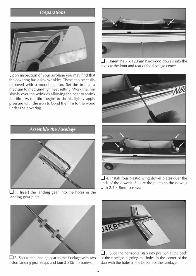
Upon inspection of your airplane you may find thatthe covering has a few wrinkles. These can be easilyremoved with a modeling iron. Set the iron at amedium to medium/high heat setting. Work the ironslowly over the wrinkles allowing the heat to shrinkthe film. As the film begins to shrink, lightly applypressure with the iron to bond the film to the woodunder the covering.
❏ 1. Insert the landing gear into the holes in thelanding gear plate.
❏ 2. Secure the landing gear to the fuselage with twonylon landing gear straps and four 3 x12mm screws.
❏ 3. Insert the 7 x 120mm hardwood dowels into theholes at the front and rear of the fuselage center.
❏ 4. Install four plastic wing dowel plates over theends of the dowels. Secure the plates to the dowelswith 2.5 x 8mm screws.
❏ 5. Slide the horizontal stab into position at the backof the fuselage aligning the holes in the center of thestab with the holes in the bottom of the fuselage.
Assemble the Fuselage
Preparations
5

❏ 6. Insert the vertical fin into the slot in the back ofthe fuselage. The metal rods should pass through theholes in the stab and fuselage.
❏ 7 Install both of the 56mm plastic stab bolts into theholes, threading them onto the wires from the stab.Tighten both of the bolts snugly against the fuselage. Donot over tighten the bolts or they could strip.
❏ 8. Install the nylon clevis into the outer hole ofthe control horn and secure it by sliding the siliconeclevis keeper over the clevis. Do the same for therudder clevis.
IMPORTANT! Do not fly the airplane without the silicone cleviskeepers on the clevises. Flying without silicone cleviskeepers could cause the clevises to fail, possiblyresulting in a crash. Inspect the silicone cleviskeepers and if they show any signs of wear, replacethem with new ones. These can be made by cutting1/4” lengths of silicone fuel tubing.
6

❏ 1. Slide the 9 x 207mm metal wing joiner into thehole in the right wing panel.
❏ 2. Slide the left wing panel onto the metal wingjoiner. Slide the wings together, making sure thealignment pin in the wing fits into the hole in theopposite wing panel.
❏ 3. Be sure the wings are tight against each other.Place the two metal wing joiner straps over the pre-drilled holes in the bottom of the wing. Secure thestraps to the wing panels with 2.5 x 8mm screws.
❏ 4. Install the aileron clevis to the control horn.Slide the silicone clevis keeper over the clevis.
HHHHooootttt TTTTiiiipppp
Here are two things you might consider to make astronger, longer-lasting wing assembly. Both arevery easy but do require the use of glue.
1. Apply epoxy glue to the root rib of each winghalf before sliding the wings together. Once thewings are pushed tightly against each other,install the metal wing joiner straps and 2.5 x8mm screws. Clean any excess epoxy from thewing with a paper towel and rubbing alcohol.
2. Put some aliphatic glue (any typical whiteglue such as Elmers®) into the screw holes, theninstall the screws. When the glue dries it will bedifficult for the screws to come loose fromvibration or wear.
Assemble the Wing
7

CHECK THE SCREWS
Your Hobbistar .60 Select is nearly a fully assembledairplane when you remove it from the box. However, itis a good idea to check the tightness of all of the screws.Systematically go through the airplane and be sure allbolts and screws are tight. Start with the enginecompartment followed by the landing gear, radiocompartment, tail surfaces and then the wing. Removethe spinner and check the propeller nut to be sure it istight; then, re-install the spinner.
CHARGE THE BATTERIES
If you have not yet charged the batteries, you may stillproceed. However, as the batteries have not been fullycharged, they may not provide enough power to makeit all the way through the setup procedures. If thebatteries quit working, charge the batteries as describedin the instruction manual for the Futaba radio systemthat came with this kit. After you complete the setupand before flying the airplane be sure to follow the nextcharging steps!
IMPORTANT!Your Hobbistar .60 Select uses NiCd batteries in thetransmitter and receiver. NiCd batteries need to beexercised or “cycled” to get full capacity from thebatteries before using them. There are several goodelectronic cyclers available. The Hobbico Accu-Cycle™
(HCAP0260) and the Accu-Cycle Elite (HCAP0280) aretwo good choices. If you have a battery cycler or if yourinstructor has one, it is recommended that you cycle thebatteries at least three times before you fly. If you do nothave access to a battery cycler, we recommend you usethe following procedure to help assure you are gettingfull capacity from you batteries.
❏ 1. Charge the transmitter and receiver batteryovernight following the instructions with the radio system.
❏ 2. Extend the transmitter antenna; turn on thetransmitter and receiver. Using the transmitter, movethe control surfaces. Continue moving the controlsurfaces until the servos slow down or quitfunctioning. This will take approximately an hour.
❏ 3. Re-charge the batteries and repeat thisprocedure. Normally doing this two or three times
will cycle the batteries adequately for safe flying. If,after repeating this a few times, you are not gettingapproximately an hour or more of operating time,repeat the procedure until you do.
CENTER THE CONTROL SURFACES
Even though the trim levers on the transmitter maybe used to center the control surfaces, you shouldstart out with the trims centered.
Do the elevator first.
❏ 1. With the transmitter and receiver on, view theelevator and stab from the end. If the elevator is notcentered, disconnect the clevis from the control hornon the elevator. Holding the end of the pushrod withpliers, screw or unscrew the clevis as necessary untilthe elevator will be centered when reconnected tothe pushrod. Note: Be sure not to unscrew the clevistoo far. It must remain securely fastened to the end ofthe pushrod.
❏ 2. Center the rudder and both ailerons the same way.
❏ 3. Now that the rudder is centered, center thenose wheel by adjusting the pushrod in the threadedconnector on the steering arm. Roll the fuselagealong a flat surface (such as your garage, basementor kitchen floor) to make certain it rolls straight. Thisshould be done with the transmitter and receiver on.Make adjustments if necessary. Add a small drop ofthreadlocker to the screw and securely tighten tolock the pushrod into position.
❏ 4. Install a silicone retainer on all the clevises(elevator, rudder, ailerons, throttle). If you'vemisplaced the retainers that came with the model,use 1/4" [6mm] pieces cut from leftover fuel tubing.
Stabilizer Elevator
Elevator NOT Centered With Stab
Elevator Centered With Stab
Prepare the Model for Flying
8

CHECK THE CONTROL DIRECTIONS
Move the control sticks on the transmitter as shownto be certain the controls on the airplane respond inthe correct direction. If any of the controls move thewrong way, use the servo reversing switches on thetransmitter to make the controls respond correctly. Ifnecessary, refer to the instructions in the instructionmanual that came with your radio to identify andoperate the reversing switches.
SET THE CONTROL THROWS
The control throws are a measure of how far theflight controls (elevator, ailerons, rudder) move upand down (or from side to side). If the controls movetoo much, the plane will respond too quickly and bedifficult to control. If the controls do not moveenough, there will not be enough control to fly orland the model. Due to the great effect the controlthrows have on the way a model flies, the controlthrows must be set according to the measurementsprovided in this manual.
Start with the elevator…
❏ 1. Turn on the transmitter and receiver. Holding a rulerup to the trailing edge of the elevator, move the elevatorall the way up using the control stick on the transmitter.Measure the distance the elevator moves up. Also movethe elevator down and measure the distance. As shownin the chart that follows, the elevator should move up1/2" [13mm] and down 1/2" [13mm]. If the elevatormoves up or down more than 1/2" [13mm], the controlthrow must be decreased by connecting the pushrod toa hole further out on the elevator control horn, or byconnecting the pushrod to a hole further in on theelevator servo arm (as shown in the sketches below). Ifthe elevator moves up and down less than 1/2" [13mm],the control throw must be increased by relocating thepushrods the opposite as described.
Control Throws
Elevator: 1/2" [13mm] up 1/2" [13mm] downAilerons: 3/8" [10mm] up 3/8" [10mm] downRudder: 1" [25mm] right 1" [25mm] left
Note that pulling the elevator stick back movesthe elevator up (which, in flight, pushes the taildown, thus raising the nose of the plane to climb).The best way to keep this in mind is to think interms of a pilot in an actual airplane. He pulls thecontrol stick back to raise the nose of the plane.
Move Stick Right
Rudder (and Nosewheel)Move Right
Move Stick Right
Right Aileron Goes Up
Left Aileron Goes Down
Pull Stick Back (Down)
Elevator Moves Up
9

To get more control surface movement, move thepushrod farther out on the servo arm. Moving thepushrod farther inward yields less control surface throw
.
To get more control surface movement, move thepushrod farther in on the control horn. Moving thepushrod farther out yields less control surface throw.
❏ 2. Measure and if necessary, adjust the aileron andrudder control throws the same way.
ADJUST THE THROTTLE
The throttle is to be set up so that, when the throttlestick is all the way down and the throttle trim lever isall the way up, the carburetor will be slightly open(so the engine will idle at a low RPM). When theengine is to be shut off, the trim lever is moved downto close the carburetor the rest of the way.
❏ 1. With the transmitter and receiver on, move the throttle trim lever and the throttle stick all theway down.
❏ 2. Observe the opening in the carburetor. If thecarburetor is fully closed, proceed to step 3. If thecarburetor is not fully closed, adjust the pushrod atthe connector on the carburetor arm or at the clevison the servo arm until the carburetor is closed.
❏ 3. Move the throttle trim lever all the way up, butleave the throttle stick all the way down. Now thecarburetor should be partially open (about 1/32" to1/16" [1 to 1.5mm]).
❏ 4. Move the throttle stick all the way up. Thecarburetor should be fully open. If the carb is not fullyopen, the pushrod travel may have to be increased.This is done by moving the clevis further out on theservo arm (or by moving the pushrod connector closerin on the carburetor arm). Adjust the pushrod asnecessary to achieve the correct setup.
Carburetor Fully Open
Trim Lever Up
ThrottleStick Down
Carburetor Partially OpenCarburetor Fully Closed
Trim Lever Down
ThrottleStick Down
MoreThrow
MoreThrow
Moving the pushrod inward on thecontrol horn results in more throw.
MoreThrow
MoreMovement
LessMovement
Moving the pushrod outward on the servoarm results in more pushrod movement.
10
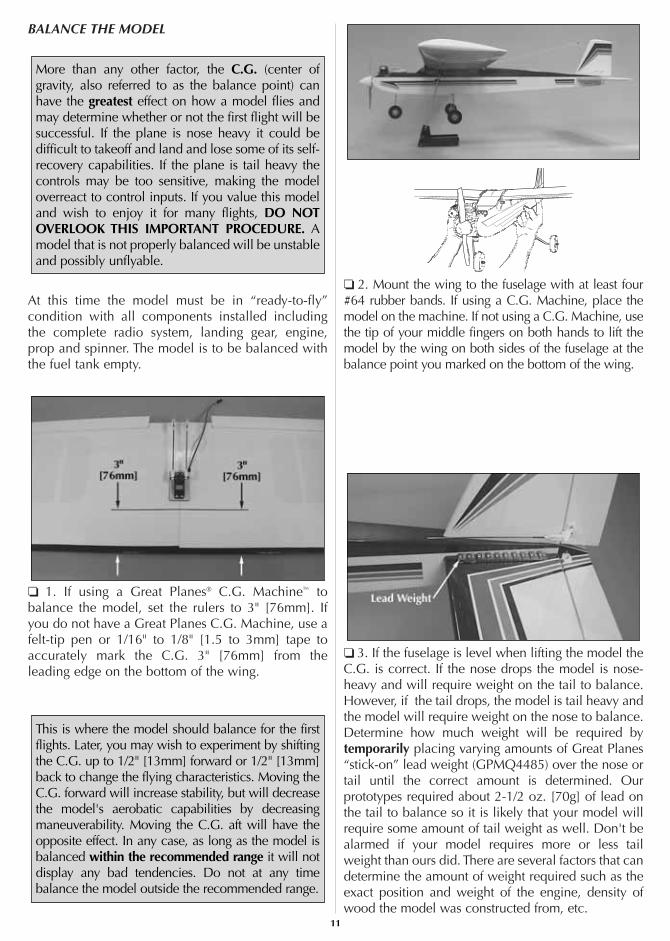
BALANCE THE MODEL
At this time the model must be in “ready-to-fly”condition with all components installed includingthe complete radio system, landing gear, engine,prop and spinner. The model is to be balanced withthe fuel tank empty.
❏ 1. If using a Great Planes® C.G. Machine™ tobalance the model, set the rulers to 3" [76mm]. Ifyou do not have a Great Planes C.G. Machine, use afelt-tip pen or 1/16" to 1/8" [1.5 to 3mm] tape toaccurately mark the C.G. 3" [76mm] from theleading edge on the bottom of the wing.
❏ 2. Mount the wing to the fuselage with at least four#64 rubber bands. If using a C.G. Machine, place themodel on the machine. If not using a C.G. Machine, usethe tip of your middle fingers on both hands to lift themodel by the wing on both sides of the fuselage at thebalance point you marked on the bottom of the wing.
❏ 3. If the fuselage is level when lifting the model theC.G. is correct. If the nose drops the model is nose-heavy and will require weight on the tail to balance.However, if the tail drops, the model is tail heavy andthe model will require weight on the nose to balance.Determine how much weight will be required bytemporarily placing varying amounts of Great Planes“stick-on” lead weight (GPMQ4485) over the nose ortail until the correct amount is determined. Ourprototypes required about 2-1/2 oz. [70g] of lead onthe tail to balance so it is likely that your model willrequire some amount of tail weight as well. Don't bealarmed if your model requires more or less tailweight than ours did. There are several factors that candetermine the amount of weight required such as theexact position and weight of the engine, density ofwood the model was constructed from, etc.
This is where the model should balance for the firstflights. Later, you may wish to experiment by shiftingthe C.G. up to 1/2" [13mm] forward or 1/2" [13mm]back to change the flying characteristics. Moving theC.G. forward will increase stability, but will decreasethe model's aerobatic capabilities by decreasingmaneuverability. Moving the C.G. aft will have theopposite effect. In any case, as long as the model isbalanced within the recommended range it will notdisplay any bad tendencies. Do not at any timebalance the model outside the recommended range.
More than any other factor, the C.G. (center ofgravity, also referred to as the balance point) canhave the greatest effect on how a model flies andmay determine whether or not the first flight will besuccessful. If the plane is nose heavy it could bedifficult to takeoff and land and lose some of its self-recovery capabilities. If the plane is tail heavy thecontrols may be too sensitive, making the modeloverreact to control inputs. If you value this modeland wish to enjoy it for many flights, DO NOTOVERLOOK THIS IMPORTANT PROCEDURE. Amodel that is not properly balanced will be unstableand possibly unflyable.
11

❏ 4. Attach weight to the model where required. If noseweight is required it should be adhered to the firewall orthe inside of one of the fuselage sides in front of thefirewall. Due to the likelihood of fuel coming intocontact with the double-sided foam tape that holds thelead in place, the best way to secure nose weight is toscrape off the foam tape and permanently glue the leadinto place with epoxy. If tail weight is required, do notsimply adhere the lead to the covering. Instead, use a pinto poke several holes in the covering over the left side ofthe fuselage (opposite the engine exhaust) under thestabilizer. Add several drops of thin CA to the area tothoroughly bond the covering to the wood. Now thelead may be stuck to the fuselage. Be certain any weightstuck to the tail does not interfere with the pushrods.
Note: An optional way to add nose weight, if required,is to use a “spinner weight” (GPMQ4645 for 1 oz.[29g] weight, or GPMQ4646 for 2 oz. [57g] weight).Spinner weights are used in place of the prop washer.
❏ 5. IMPORTANT: If you found it necessary to addany weight, recheck the C.G. after the weight hasbeen added.
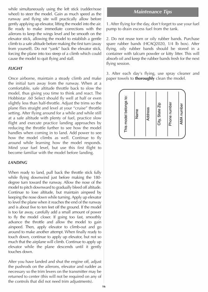
IDENTIFY YOUR MODEL
Whether you fly at an R/C club or somewhere on yourown, you should have your name, telephone numberand address in or on your model so it can be identifiedand returned in case it lands somewhere away from theflying site. Fill out the I.D. tag found at the end of themanual and place it on or inside the model.
BALANCE PROPELLERS
To inexperienced modelers balancing propellers mayseem unnecessary. Balancing propellers could beequated to changing the oil in your car every 3000miles. If not done regularly, the car keeps running, butover time poor maintenance will take its toll. Similarly,the engine will run and the plane will fly even if thepropeller is not balanced. But over time, not only mayan unbalanced propeller cause engine mounting screwsand bolts to loosen, possibly with disastrous effect, butvibration may also damage the radio receiver andbattery. Vibration can also cause fuel to foam, whichwill, in turn, cause the engine to run hot or quit.If you do not yet have a propeller balancer, ask yourflight instructor or another club member if they willhelp you balance your propellers. We use a Top FlitePrecision Magnetic Prop Balancer™ (TOPQ5700) inthe workshop and keep a Great Planes Fingertip PropBalancer (GPMQ5000) in our flight box.
12

CHARGE THE BATTERIES
If you haven't already done so, refer to theinstruction manual that came with the radio andcharge the batteries in the plane and in thetransmitter overnight the night before you go flying.
GATHER YOUR TOOLS
In addition to the engine starting equipmentmentioned near the beginning of the manual, youshould start a collection of tools that may be requiredfor adjustments and maintenance at the flying field.Following is a list of the most suggested items…
Tools:❏ #1 Phillips screwdriver❏ #2 Phillips screwdriver❏ 5/16" (or 8mm) socket wrench (for glow plug)❏ 1.5mm hex wrench (for wheel collars)❏ 12mm wrench or crescent wrench (for propeller nut)❏ Pliers❏ Hobby knife
Spare parts:❏ Suitable propellers❏ Glow plug❏ #64 rubber bands (stored in container with talcumpowder or kitty litter to absorb excess oil after use.)
Flight preparation is to be done at the flying field.
Be certain your flight instructor performs thesefollowing checks with you.
CHECK THE CONTROLS
1. Get the frequency clip from the frequency controlboard at your flying site.
2. Mount the wing to the fuselage with #64 rubberbands. Twelve to fourteen rubber bands aresuggested. Be certain the final two are “crisscrossed,”thus ensuring that the others remain secure.
3. Turn on the transmitter and receiver. One at atime, operate each control on the airplane using thetransmitter. Make certain each control is respondingcorrectly. This must be done before every flight.There are several types of malfunctions that can bediscovered by performing this elementary task, thussaving your model!
IMPORTANT:Your radio control system transmits asignal on a certain frequency. Be certain you knowwhat the frequency is. This is expressed as a two-digit number (42, 56, etc.) and can be found on thecontainer the radio system came in and is alsolocated on the transmitter and receiver. There aremany different frequencies, but there is still achance that someone else at the flying field may beon the same frequency as you. If you turn on yourtransmitter while that person is flying, a crash willresult. NEVER turn on your transmitter until youhave permission from your instructor and until youhave possession of the frequency clip used forfrequency control at the flying site.
Flight PreparationCHECKLIST
Now it's time to do a final check before taking themodel to the field. Take the time to do thesechecks to make certain your model is ready to fly.
❏ 1. Make certain the screws on all the wheelcollars that hold the wheels on are secure.Threadlocker is recommended on the screws.
❏ 2. Check to see that the screws that hold the servoarms to the servos are present and secure.
❏ 3. Be certain the silicone retainers on all thenylon clevises are in position.
❏ 4. Make certain the throttle, elevator, rudderand ailerons respond in the correct direction.
❏ 5. Make certain the propeller and propellerspinner are secure.
❏ 6. Balance the model according to the instructions.❏ 7. Fill out and place the I.D. card inside the model.❏ 8. Balance the propeller and spare propellers.
13

RANGE CHECK THE RADIO
A range check must be performed before the firstflight of a new model. It is not necessary to do arange check before every flight (but is not a bad ideato perform a range check before the first flight ofeach day). A range check is the final opportunity toreveal any radio malfunctions and to be certain thesystem has adequate operational range.
1. BE CERTAIN you have the frequency clip.
2. Turn on the transmitter and receiver. Leave thetransmitter antenna all the way down. Walk away fromthe model while simultaneously operating the controls.Have an assistant stand by the model and tell you whatthe controls are doing to confirm that they operatecorrectly. You should be able to walk approximately100 feet from the model and still have control withoutany “glitching” or inadvertent servo operation.
3. If everything operates correctly, return to the modeland start the engine. Perform the range check withyour assistant holding the plane with the enginerunning at various speeds. If the servos chatter ormove inadvertently, there may be a problem. Do notfly the plane! With the assistance of your instructor,look for loose servo connections or binding pushrods.Also be certain you are the only one on yourfrequency and that the battery has been fully charged.
GROUND CHECK
If the engine is new, follow the engine manufacturer'sinstructions to break-in the engine. After break-in,confirm that the engine idles reliably, transitionssmoothly and rapidly to full power and maintains fullpower—indefinitely. After you run the engine on themodel, inspect the model closely to make sure allscrews remained tight, the hinges are secure, the propis secure and all pushrods and connectors are secure.
Keep all engine fuel in a safe place, away from highheat, sparks or flames, as fuel is very flammable. Donot smoke near the engine or fuel; and rememberthat engine exhaust gives off a great deal of deadlycarbon monoxide. Therefore do not run the engine ina closed room or garage.
Get help from an experienced pilot when learning tooperate engines.
Use safety glasses when starting or running engines.
Do not run the engine in an area of loose gravel orsand; the propeller may throw such material in yourface or eyes.
Keep your face and body as well as all spectatorsaway from the plane of rotation of the propeller asyou start and run the engine.
Keep these items away from the prop: loose clothing,shirt sleeves, ties, scarfs, long hair or loose objectssuch as pencils or screwdrivers that may fall out ofshirt or jacket pockets into the prop.
Use a “chicken stick” or electric starter to start theengine. Do not use your fingers to flip the propeller.Make certain the glow plug clip or connector issecure so that it will not pop off or otherwise get intothe running propeller.
Make all engine adjustments from behind therotating propeller.
The engine gets hot! Do not touch it during or rightafter operation. Make sure fuel lines are in goodcondition so fuel will not leak onto a hot engine,causing a fire.
To stop a glow engine, cut off the fuel supply by closingoff the fuel line or following the engine manufacturer'srecommendations. Do not use hands, fingers or anyother body part to try to stop the engine. Do not throwanything into the propeller of a running engine.
Read and abide by the following Academy of ModelAeronautics Official Safety Code:
GENERAL1. I will not fly my model aircraft in sanctionedevents, air shows, or model flying demonstrationsuntil it has been proven to be airworthy by havingbeen previously successfully flight tested.
2. I will not fly my model aircraft higher thanapproximately 400 feet within 3 miles of an airportwithout notifying the airport operator. I will give rightof way to and avoid flying in the proximity of fullscale aircraft. Where necessary an observer shall beused to supervise flying to avoid having models fly inthe proximity of full scale aircraft.
AMA Safety Code (excerpt)
Failure to follow these safety precautions mayresult in severe injury to yourself and others.
Engine Safety Precautions
14

3. Where established, I will abide by the safetyrules for the flying site I use and I will not willfullyand deliberately fly my models in a careless, recklessand/or dangerous manner.
7. I will not fly my model unless it is identified withmy name and address or AMA number, on or in themodel.
9. I will not operate models with pyrotechnics (anydevice that explodes, burns, or propels a projectileof any kind).
RADIO CONTROL1. I will have completed a successful radioequipment ground check before the first flight of anew or repaired model.
2. I will not fly my model aircraft in the presence ofspectators until I become a qualified flier, unlessassisted by an experienced helper.
3. I will perform my initial turn after takeoff away fromthe pit or spectator areas and I will not thereafter fly overpit or spectator areas, unless beyond my control.
4. I will operate my model using only radio controlfrequencies currently allowed by the FederalCommunications Commission...
These flying instructions are not an endorsement forlearning to fly on your own, but are printed so youcan know what to expect and what to concentrate onwhile learning under the tutelage of your instructor.Further, these flight instructions may be referencedonce you finally do begin flying on your own.
TAXIING
Remember, it is assumed that your instructor isoperating the model for you.
Before the model is ready for takeoff, it must first be setup to roll straight down the runway. With the enginerunning at a low idle, place the plane on the runwayand, if your flying field permits, stand behind the model.Advance the throttle just enough to allow the model toroll. If the model does not roll straight down the runway,shut the engine off and adjust the nose gear pushrod asnecessary. Do not use the rudder trim to correct the nosewheel because this will also affect the rudder. Note:Crosswinds may affect the direction the model rolls, sothis test should be done in calm conditions, or with themodel facing directly into the wind.
TAKEOFF
If possible, takeoff directly into the wind. If you areexperienced, taking off in a crosswind is permissible(and sometimes necessary—depending upon theprevailing wind conditions and runway heading). Takingoff into the wind will help the model roll on a straightpath and also reduces ground speed for takeoff. Taxi themodel onto the runway or have an assistant carry it outand set it down, pointing into the wind down therunway. When ready, gradually advance the throttle
CAUTION (THIS APPLIES TO ALL R/C AIRPLANES):If, while flying, you notice an alarming or unusualsound such as a low-pitched “buzz,” this mayindicate control surface flutter. Flutter occurs when acontrol surface (such as an aileron or elevator) or aflying surface (such as a wing or stab) rapidly vibratesup and down (thus causing the noise). In extremecases, if not detected immediately, flutter can actuallycause the control surface to detach or the flyingsurface to fail, thus causing loss of control followedby an impending crash. The best thing to do whenflutter is detected is to slow the model immediatelyby reducing power, then land as soon as safelypossible. Identify which surface fluttered (so theproblem may be resolved) by checking all the servogrommets for deterioration or signs of vibration.Make certain all pushrod linkages are secure and freeof play. If it fluttered once, under similarcircumstances it will probably flutter again unless theproblem is fixed. Some things which can cause flutterare; Excessive hinge gap; Not mounting control hornssolidly; Poor fit of clevis pin in horn; Side-play of wirepushrods caused by large bends; Excessive free playin servo gears; Insecure servo mounting; and one ofthe most prevalent causes of flutter; Flying an over-powered model at excessive speeds.
IMPORTANT: If you do insist on flying on your own,you must be aware of your proximity to R/C clubsites. If there is an R/C site within six miles of whereyou are flying and if you are operating your modelon the same frequency as somebody else, there is astrong possibility that one or both models will crashdue to radio interference. There is great potential foran out-of-control model to cause property damageand/or severe personal injury. We strongly urge youto fly at a R/C club site where frequency control isin effect so you can be confident you will be theonly one flying on your channel.
Flying
15
while simultaneously using the left stick (rudder/nosewheel) to steer the model. Gain as much speed as therunway and flying site will practically allow beforegently applying up elevator, lifting the model into the air.Be ready to make immediate corrections with theailerons to keep the wings level and be smooth on theelevator stick, allowing the model to establish a gentleclimb to a safe altitude before making the first turn (awayfrom yourself). Do not “yank” back the elevator stick,forcing the plane into too steep of a climb which couldcause the model to quit flying and stall.
FLIGHT
Once airborne, maintain a steady climb and makethe initial turn away from the runway. When at acomfortable, safe altitude throttle back to slow themodel, thus giving you time to think and react. TheHobbistar .60 Select should fly well at half or evenslightly less than half-throttle. Adjust the trims so theplane flies straight and level at your “cruise” throttlesetting. After flying around for a while and while stillat a safe altitude with plenty of fuel, practice slowflight and execute practice landing approaches byreducing the throttle further to see how the modelhandles when coming in to land. Add power to seehow the model climbs as well. Continue to flyaround while learning how the model responds.Mind your fuel level, but use this first flight tobecome familiar with the model before landing.
LANDING
When ready to land, pull back the throttle stick fullywhile flying downwind just before making the 180-degree turn toward the runway. Allow the nose of themodel to pitch downward to gradually bleed off altitude.Continue to lose altitude, but maintain airspeed bykeeping the nose down while turning. Apply up elevatorto level the plane when it reaches the end of the runwayand is about five to ten feet off the ground. If the modelis too far away, carefully add a small amount of powerto fly the model closer. If going too fast, smoothlyadvance the throttle and allow the model to gainairspeed. Then, apply elevator to climb-out and goaround to make another attempt. When finally ready totouch down, continue to apply up elevator, but not somuch that the airplane will climb. Continue to apply upelevator while the plane descends until it gently touches down.
After you have landed and shut the engine off, adjustthe pushrods on the ailerons, elevator and rudder asnecessary so the trim levers on the transmitter may bereturned to center (this will not be required on any ofthe controls that did not need trim adjustments).
1. After flying for the day, don't forget to use your fuelpump to drain excess fuel from the tank.
2. Do not reuse torn or oily rubber bands. Purchasespare rubber bands (HCAQ2020, 1/4 lb box). Afterflying, oily rubber bands should be stored in acontainer with talcum powder or kitty litter. This willabsorb oil and keep the rubber bands fresh for the nextflying session.
3. After each day's flying, use spray cleaner andpaper towels to thoroughly clean the model.
Maintenance Tips
16