assembly instructions prorunner mk5 · assembly instructions prorunner mk5 9 2.2 installation...
TRANSCRIPT
Assembly instructions PRORUNNER mk5
Version 2.0 / 01-JUN-2013

Assembly instructions PRORUNNER mk5
2
Copyright © Qimarox B.V. All rights reserved. No part of this document may be copied, stored in a database and/or published by means of printing, photocopying, microfilming or by any other means whatsoever without the prior written permission from Qimarox B.V.
Assembly instructions PRORUNNER mk5
3
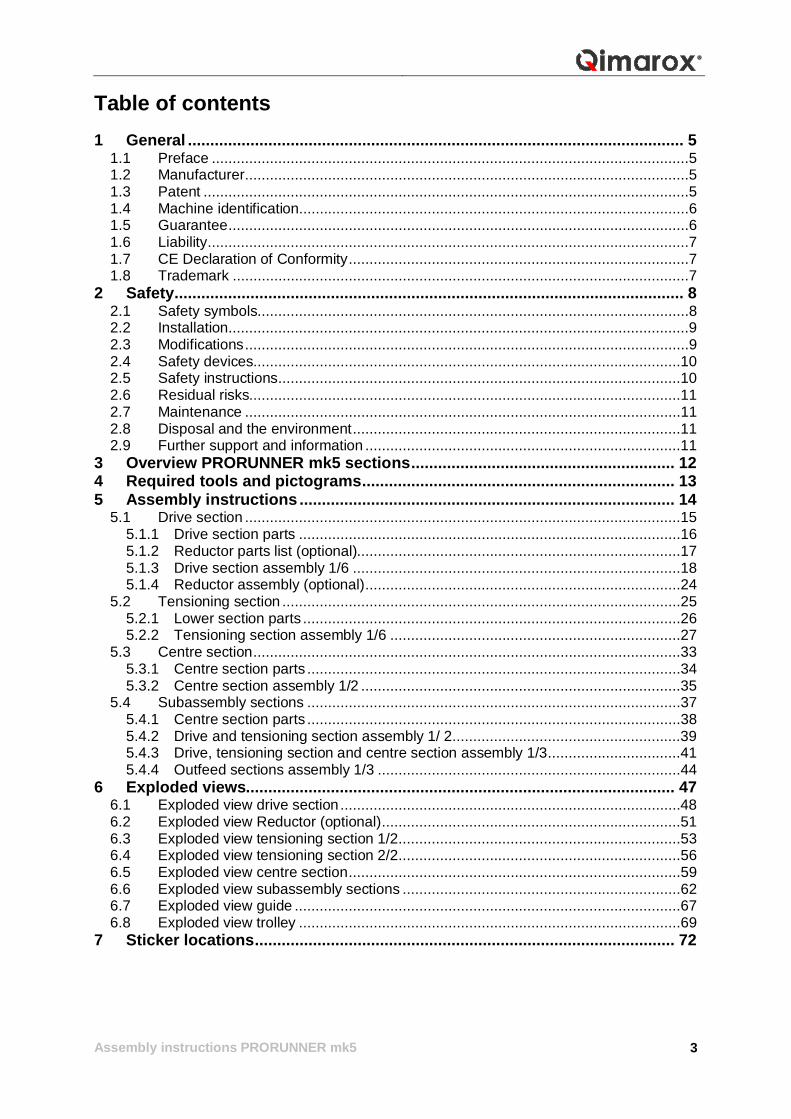
Table of contents 1 General ............................................................................................................... 5
1.1 Preface ...................................................................................................................5 1.2 Manufacturer ...........................................................................................................5 1.3 Patent .....................................................................................................................5 1.4 Machine identification..............................................................................................6 1.5 Guarantee ...............................................................................................................6 1.6 Liability ....................................................................................................................7 1.7 CE Declaration of Conformity ..................................................................................7 1.8 Trademark ..............................................................................................................7
2 Safety .................................................................................................................. 8 2.1 Safety symbols........................................................................................................8 2.2 Installation ...............................................................................................................9 2.3 Modifications ...........................................................................................................9 2.4 Safety devices.......................................................................................................10 2.5 Safety instructions .................................................................................................10 2.6 Residual risks........................................................................................................11 2.7 Maintenance .........................................................................................................11 2.8 Disposal and the environment ...............................................................................11 2.9 Further support and information ............................................................................11
3 Overview PRORUNNER mk5 sections ........................................................... 12 4 Required tools and pictograms ...................................................................... 13 5 Assembly instructions .................................................................................... 14
5.1 Drive section .........................................................................................................15 5.1.1 Drive section parts ............................................................................................16 5.1.2 Reductor parts list (optional)..............................................................................17 5.1.3 Drive section assembly 1/6 ...............................................................................18 5.1.4 Reductor assembly (optional) ............................................................................24
5.2 Tensioning section ................................................................................................25 5.2.1 Lower section parts ...........................................................................................26 5.2.2 Tensioning section assembly 1/6 ......................................................................27
5.3 Centre section .......................................................................................................33 5.3.1 Centre section parts ..........................................................................................34 5.3.2 Centre section assembly 1/2 .............................................................................35
5.4 Subassembly sections ..........................................................................................37 5.4.1 Centre section parts ..........................................................................................38 5.4.2 Drive and tensioning section assembly 1/ 2 .......................................................39 5.4.3 Drive, tensioning section and centre section assembly 1/3 ................................41 5.4.4 Outfeed sections assembly 1/3 .........................................................................44
6 Exploded views................................................................................................ 47 6.1 Exploded view drive section ..................................................................................48 6.2 Exploded view Reductor (optional) ........................................................................51 6.3 Exploded view tensioning section 1/2 ....................................................................53 6.4 Exploded view tensioning section 2/2 ....................................................................56 6.5 Exploded view centre section ................................................................................59 6.6 Exploded view subassembly sections ...................................................................62 6.7 Exploded view guide .............................................................................................67 6.8 Exploded view trolley ............................................................................................69
7 Sticker locations .............................................................................................. 72
Assembly instructions PRORUNNER mk5
4
Assembly instructions PRORUNNER mk5
5
1 General This chapter provides general information about the PRORUNNER mk5 and these assembly instructions. 1.1 Preface These are the assembly instructions for the PRORUNNER mk5 product lift manufactured by Qimarox B.V. These instructions include all information that is important to you, the installer and/or user, to assemble the PRORUNNER mk5. The assembly instructions are intended for: resellers/OEMs (installers) end users (technical department)
These assembly instructions are a supplement to the user manual. Always consult the user manual before use. 1.2 Manufacturer Qimarox B.V. Nobelstraat 43 3846 CE Harderwijk The Netherlands Tel:+31 341 436 700 Fax:+31 341 436 701 Email:[email protected] Internet: www.qimarox.com. 1.3 Patent Patent protection applies to parts of this machine. Consequently, it is not permitted for other parties to build this product in this form unless Qimarox B.V. has given explicit permission to do so. For the list of applicable patents, see:mk5patents.qimarox.com
Assembly instructions PRORUNNER mk5
6
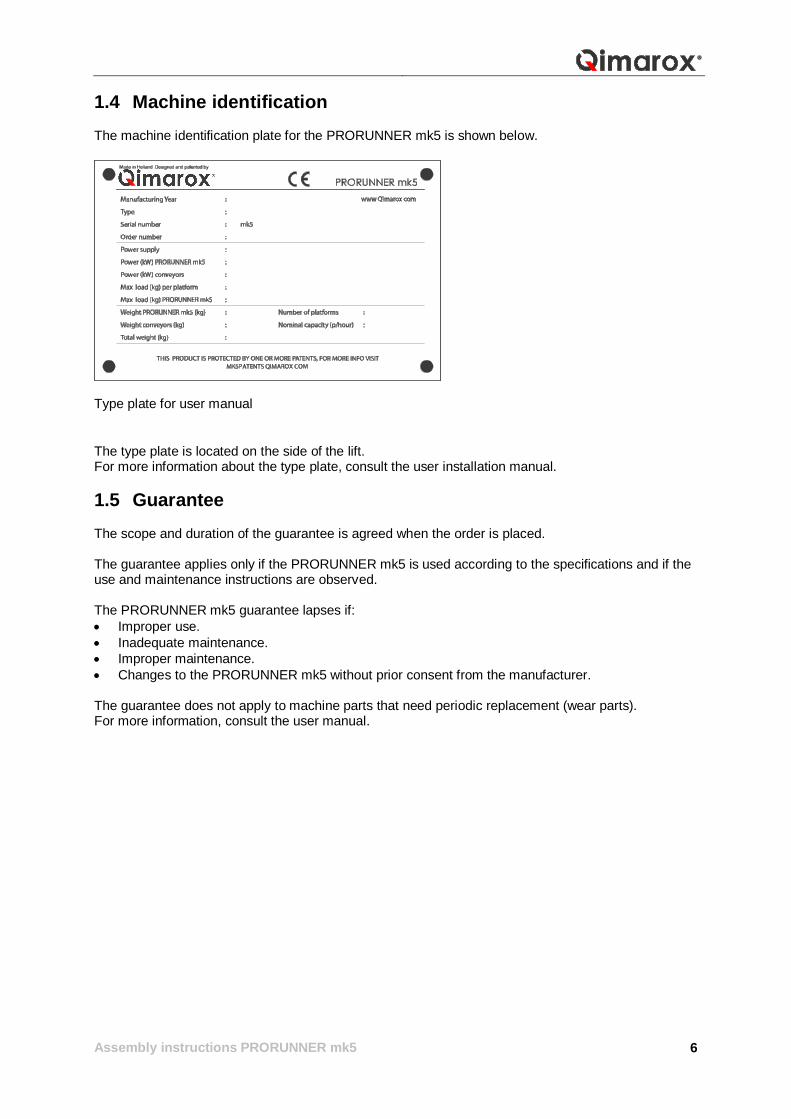
1.4 Machine identification The machine identification plate for the PRORUNNER mk5 is shown below.
Type plate for user manual The type plate is located on the side of the lift. For more information about the type plate, consult the user installation manual. 1.5 Guarantee The scope and duration of the guarantee is agreed when the order is placed. The guarantee applies only if the PRORUNNER mk5 is used according to the specifications and if the use and maintenance instructions are observed. The PRORUNNER mk5 guarantee lapses if: Improper use. Inadequate maintenance. Improper maintenance. Changes to the PRORUNNER mk5 without prior consent from the manufacturer.
The guarantee does not apply to machine parts that need periodic replacement (wear parts). For more information, consult the user manual.

Assembly instructions PRORUNNER mk5
7
1.6 Liability Qimarox B.V. is not liable for unsafe situations, accidents and damage resulting from: Failing to observe warnings or rules displayed on the machine or described in these assembly
instructions. Using the machine for applications or under circumstances other than known at the time the order
is placed with Qimarox B.V. Modifying the machine in any way. This also applies to replacement parts other than those specified in these assembly instructions.
Inadequate maintenance. 1.7 CE Declaration of Conformity The machine complies with the essential requirements regarding safety and hygiene. For the guidelines that led to the design: see the CE Declaration annex of the user manual. 1.8 Trademark
The following terms are trademarks of Qimarox B.V. in the United States of America, the Netherlands and/or possibly other countries: Qimarox B.V. PRORUNNER.
All other trademarks are the property of their respective owners.

Assembly instructions PRORUNNER mk5
8
2 Safety The responsibility of Qimarox B.V. lapses if the user does not comply with the guidelines and instructions provided in these assembly instructions for the assembly and construction of the PRORUNNER mk5. 2.1 Safety symbols The following symbols are used in these assembly instructions:
Risk of damage to the PRORUNNER Mk5 if the instructions are not followed carefully.
Risk of serious injury to the user if the instructions are not followed carefully.
The following safety symbols may be attached to the PRORUNNER:
Danger for which the additional precautions described in this manual must be taken.
Danger of electrical voltage, attached to the control cabinets
Instructions for switching off the machine before carrying out maintenance activities, attached to the side frame of the machine.
No access beyond this point, attached to every access door or opening before reaching the danger zone.
Risk of trapping upper limbs, if applicable attached near the openings near the forks for the infeed and outfeed roller tracks.
Risk of trapping upper limbs between moving rollers, if applicable attached near the infeed and outfeed roller tracks.
Assembly instructions PRORUNNER mk5
9
2.2 Installation
Before the PRORUNNER mk5 is put into service, all of the parts the machine is composed of must comply with the applicable local regulations. See the user manual for installation instructions. Feel free to contact Qimarox B.V if you need assistance.
The PRORUNNER mk5 may only be assembled by qualified personnel.
The safety instructions stated in this manual must be observed. Deviating from the instructions may result in unacceptable risks!
The installer must be familiar with the contents of the user manual. 2.3 Modifications
Modifications that can affect the safety of the product lift may only be carried out with the permission from persons authorised by the directors.
Do not make any modifications that conflict with the local, regional or national legislation.
Ensure that the on/off switch is readily accessible.
Qimarox B.V. is always willing to discuss improvements by modifications to the machine. See Further support and information in the user manual.

Assembly instructions PRORUNNER mk5
10
2.4 Safety devices
It is not permitted to disassemble, bypass or disable any safety devices. See the user manual for the required references.
The PRORUNNER mk5 may not be started or must be immediately taken out of service if one of the safety devices is defective.
The PRORUNNER mk5 must be equipped with the following safety devices: Emergency stop
Use the emergency stop (A) in the event of an an emergency.
Fencing Qimarox B.V is obliged to guard the PRORUNNER mk5 with a fence. The access door(s) must be secured with (interlock) door switches. These switches must be included in the emergency stop circuit.
The doors must not never be closed if someone is inside the fencing.
The machine must be switched off and secured when prolonged work is carried out inside the fencing.
Always put all of the safety devices that were removed back in place as soon as maintenance work has been completed.
2.5 Safety instructions Observe the following general safety instructions:
Connect the PRORUNNER mk5 in accordance with the basic health and safety requirements of the relevant European directives.
Before you put the PRORUNNER mk5 into service, check that the machine has been installed in accordance with the instructions in this manual.
Never switch on the power to the PRORUNNER mk5 or start the PRORUNNER mk5 if there are people in contact with the machine or if there are people inside the danger zones.
Switch off the power to the machine using the main switch before carrying out any maintenance or repair work on the PRORUNNER mk5. Secure the main switch with a padlock.
Keep your hands away from danger zones. Be careful of loose clothing and hair. Wear head protection. Make sure there are no people or objects within reach of the moving parts of the
PRORUNNER mk5.
Replace damaged or defective parts before putting the PRORUNNER mk5 into service again. Maintenance of the PRORUNNER mk5 must be carried out by trained engineers. Always be on the alert for dangerous situations.
Assembly instructions PRORUNNER mk5
11
2.6 Residual risks The machine is intended to be integrated into a transport system. Qimarox B.V has covered potential dangers as much as possible. Eliminate or guard the following residual risks before putting the whole assembly into service:
Risk of injury caused by falling products. Risk of injury as a result of moving product holders. Danger that occurs in places where the PRORUNNER mk5 connects to other parts of the
production line. The interior of the machine is accessible through the large openings in the front frame. Guards may also be required for the supply, output, infeed and outfeed conveyors. All other sides of the machine do not need extra screening. However, one must, if the top cover on the rear is accessible, make sure that the recess for the electric motor is not too large and possibly take measures to make the recess smaller or inaccessible. If the machine is not only accessible from ground level, guard the places where this may cause danger. 2.7 Maintenance The PRORUNNER mk5 may only be maintained by qualified personnel.
The safety instructions stated in the user manual must be observed. Deviating from the instructions may result in unacceptable risks! Only use spare parts from Qimarox B.V.
The maintenance engineer must be familiar with the contents of the user manual. 2.8 Disposal and the environment Use and maintenance of the lift do not bring along any environmental risks. All parts can be disposed of as customary.
ENVIRONMMENT Consider local legislation, rules, instructions and precautions regarding safety, health and the environment.
2.9 Further support and information Qimarox B.V. is committed to providing the best user support. The support may include the following: Training Installation assistance Service contracts
Contact Qimarox B.V. for more information.
Assembly instructions PRORUNNER mk5
12
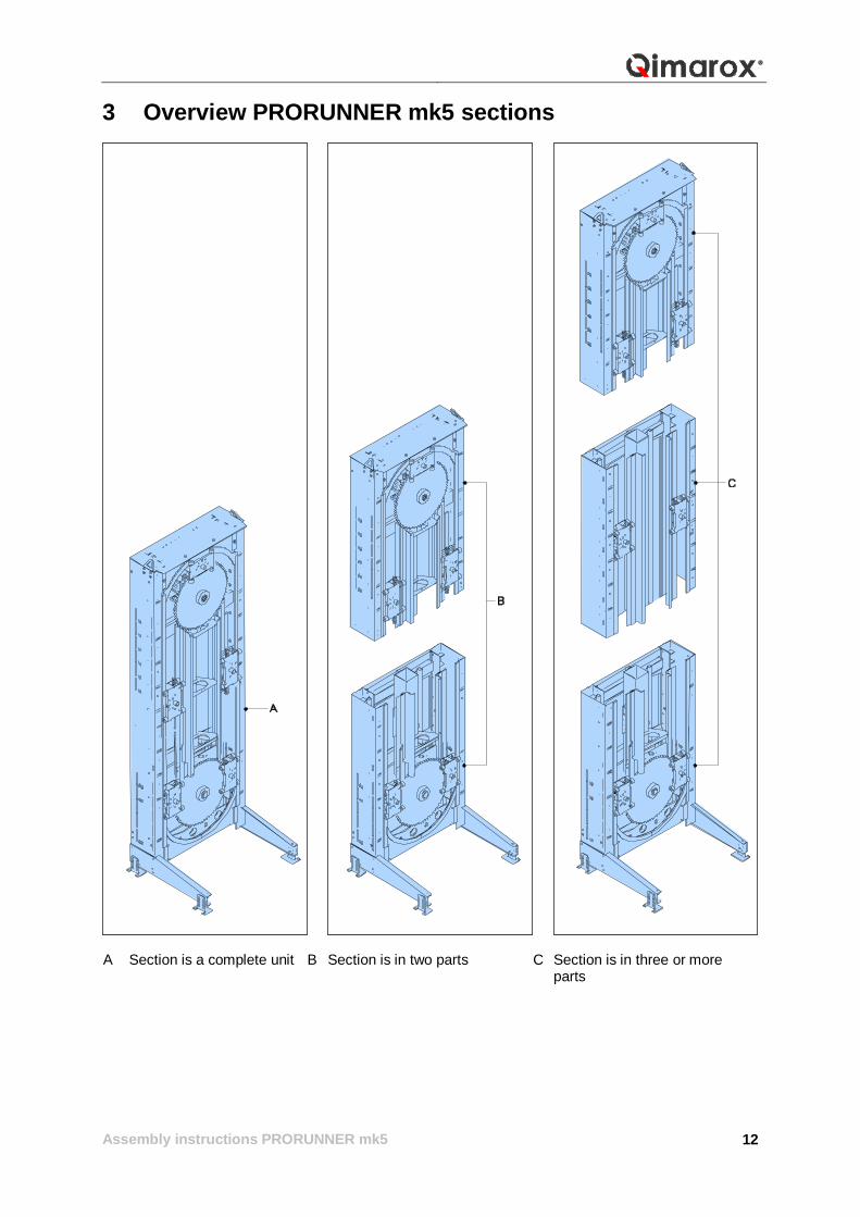
3 Overview PRORUNNER mk5 sections
A Section is a complete unit B Section is in two parts C Section is in three or more
parts
Assembly instructions PRORUNNER mk5
13
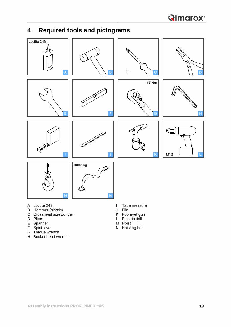
4 Required tools and pictograms
A Loctite 243 I Tape measure B Hammer (plastic) J File C Crosshead screwdriver K Pop rivet gun D Pliers L Electric drill E Spanner M Hoist F Spirit level N Hoisting belt G Torque wrench H Socket head wrench

Assembly instructions PRORUNNER mk5
14
5 Assembly instructions
Assembly instructions PRORUNNER mk5
15
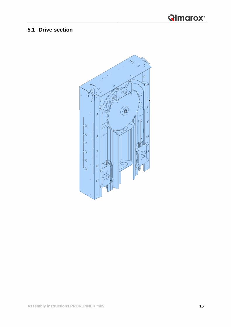
5.1 Drive section
Assembly instructions PRORUNNER mk5
16
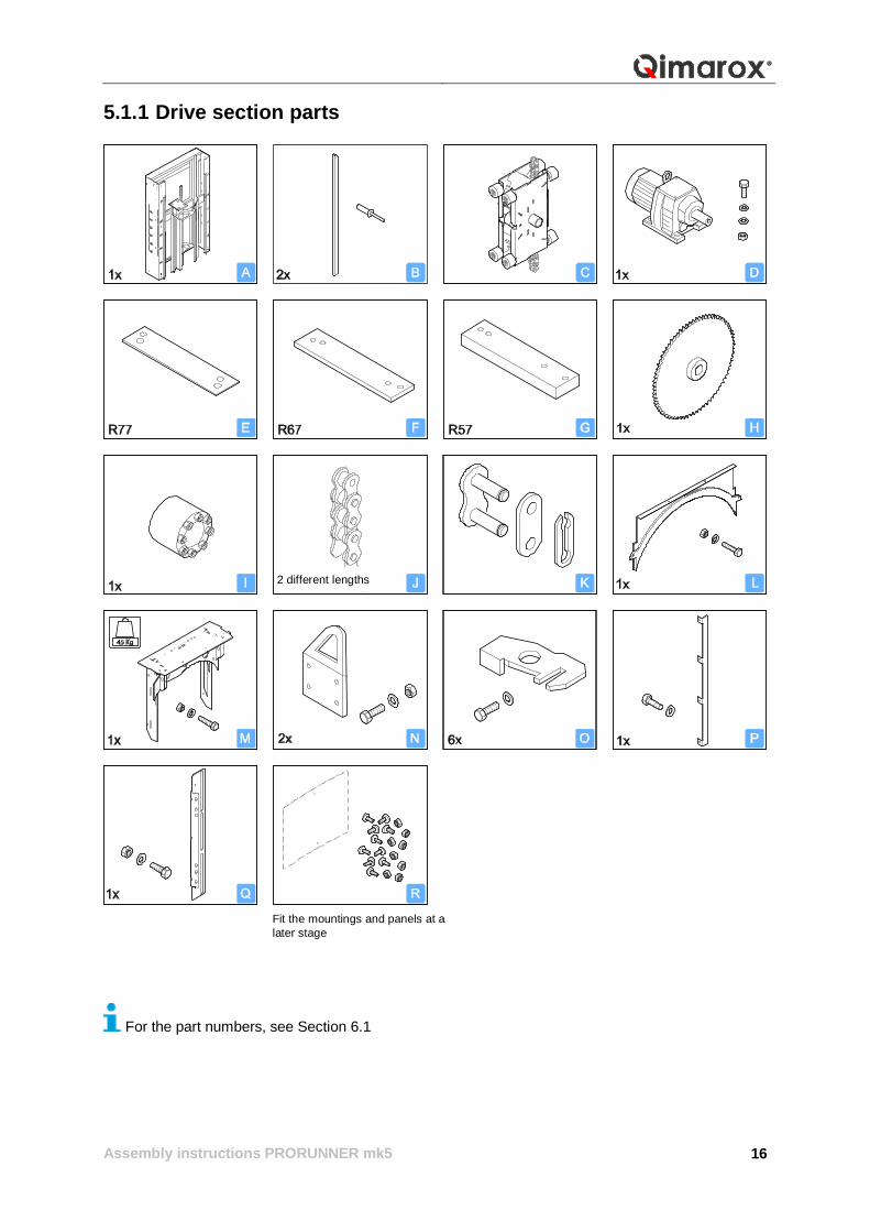
5.1.1 Drive section parts
For the part numbers, see Section 6.1
2 different lengths
Fit the mountings and panels at a later stage
Assembly instructions PRORUNNER mk5
17
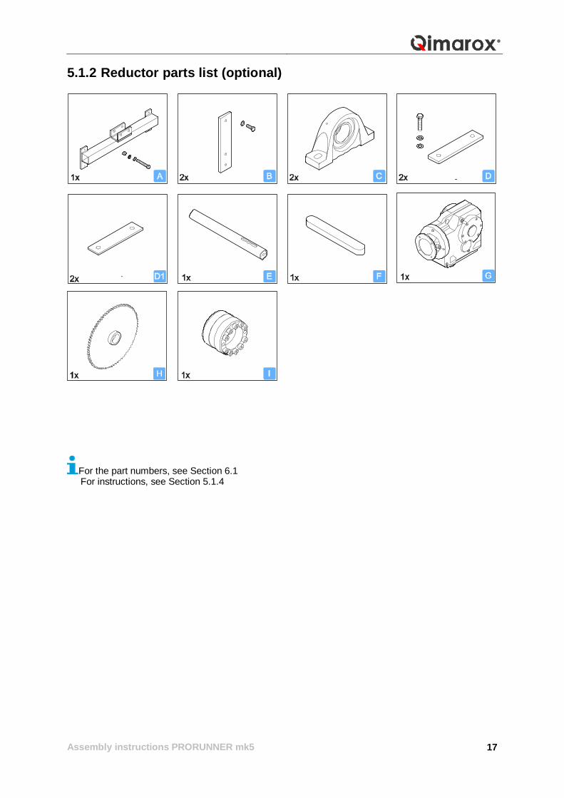
5.1.2 Reductor parts list (optional)
For the part numbers, see Section 6.1 For instructions, see Section 5.1.4
Assembly instructions PRORUNNER mk5
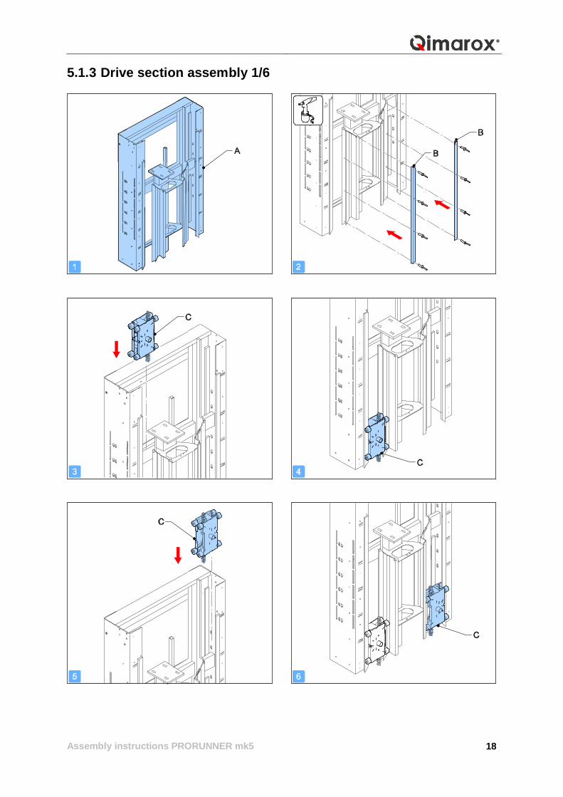
18
5.1.3 Drive section assembly 1/6
Assembly instructions PRORUNNER mk5
19
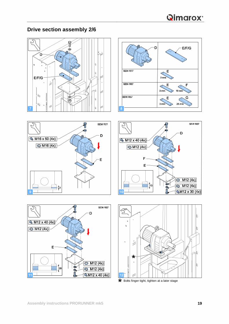
Drive section assembly 2/6
Bolts finger tight, tighten at a later stage
Assembly instructions PRORUNNER mk5
20
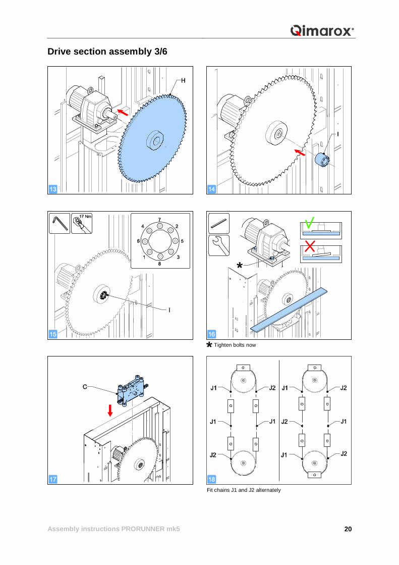
Drive section assembly 3/6
Tighten bolts now
Fit chains J1 and J2 alternately
Assembly instructions PRORUNNER mk5
21
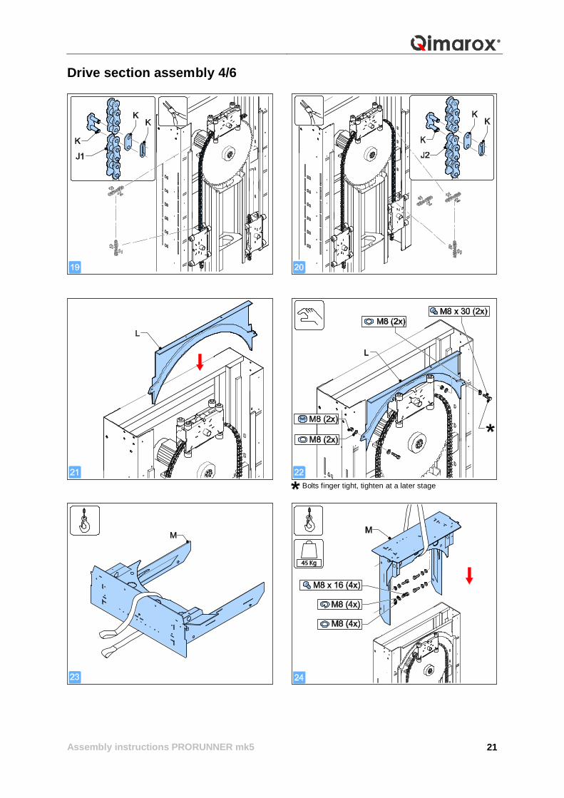
Drive section assembly 4/6
Bolts finger tight, tighten at a later stage
Assembly instructions PRORUNNER mk5
22
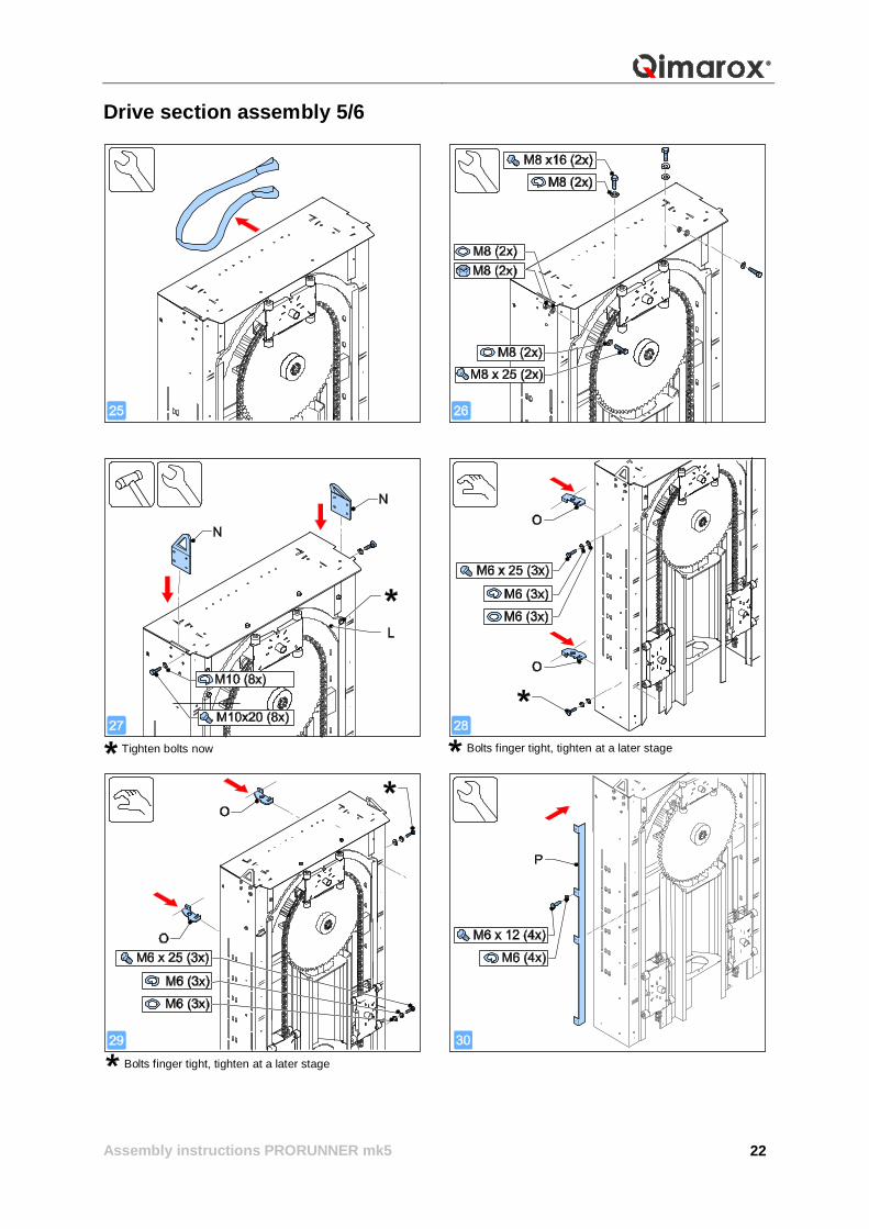
Drive section assembly 5/6
Bolts finger tight, tighten at a later stage
Bolts finger tight, tighten at a later stage
Tighten bolts now
Assembly instructions PRORUNNER mk5
23
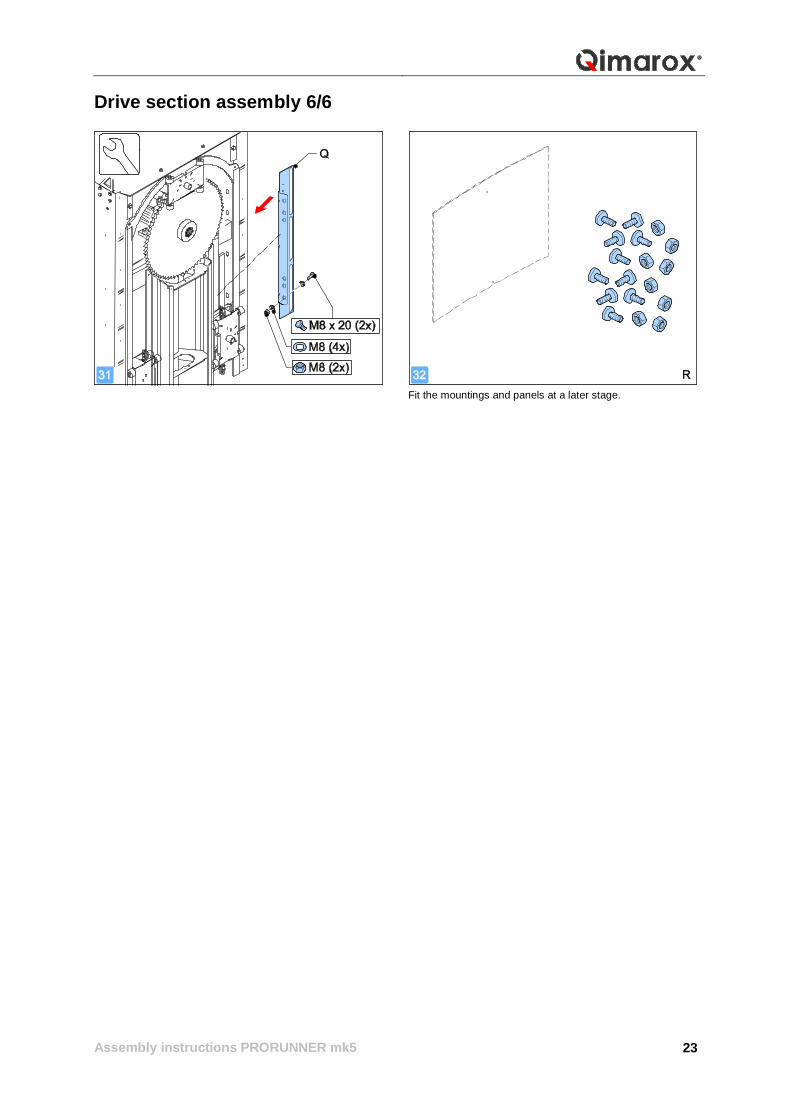
Drive section assembly 6/6
Fit the mountings and panels at a later stage.
Assembly instructions PRORUNNER mk5
24
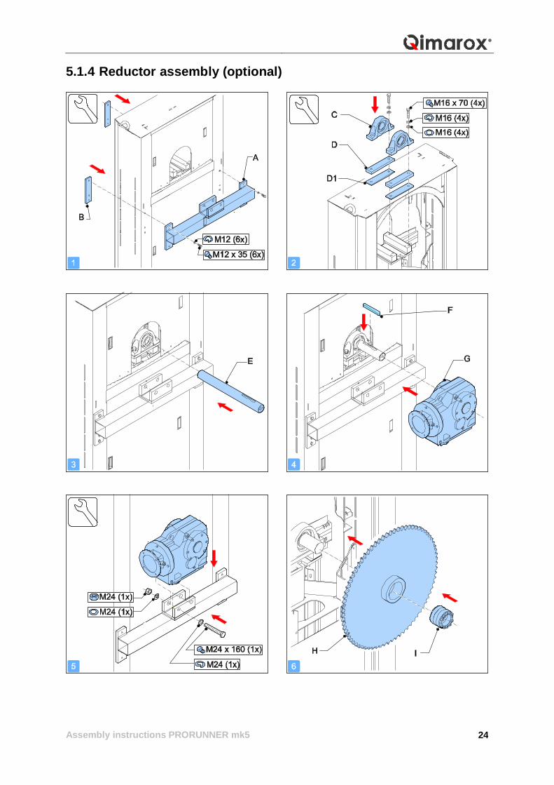
5.1.4 Reductor assembly (optional)
Assembly instructions PRORUNNER mk5
25
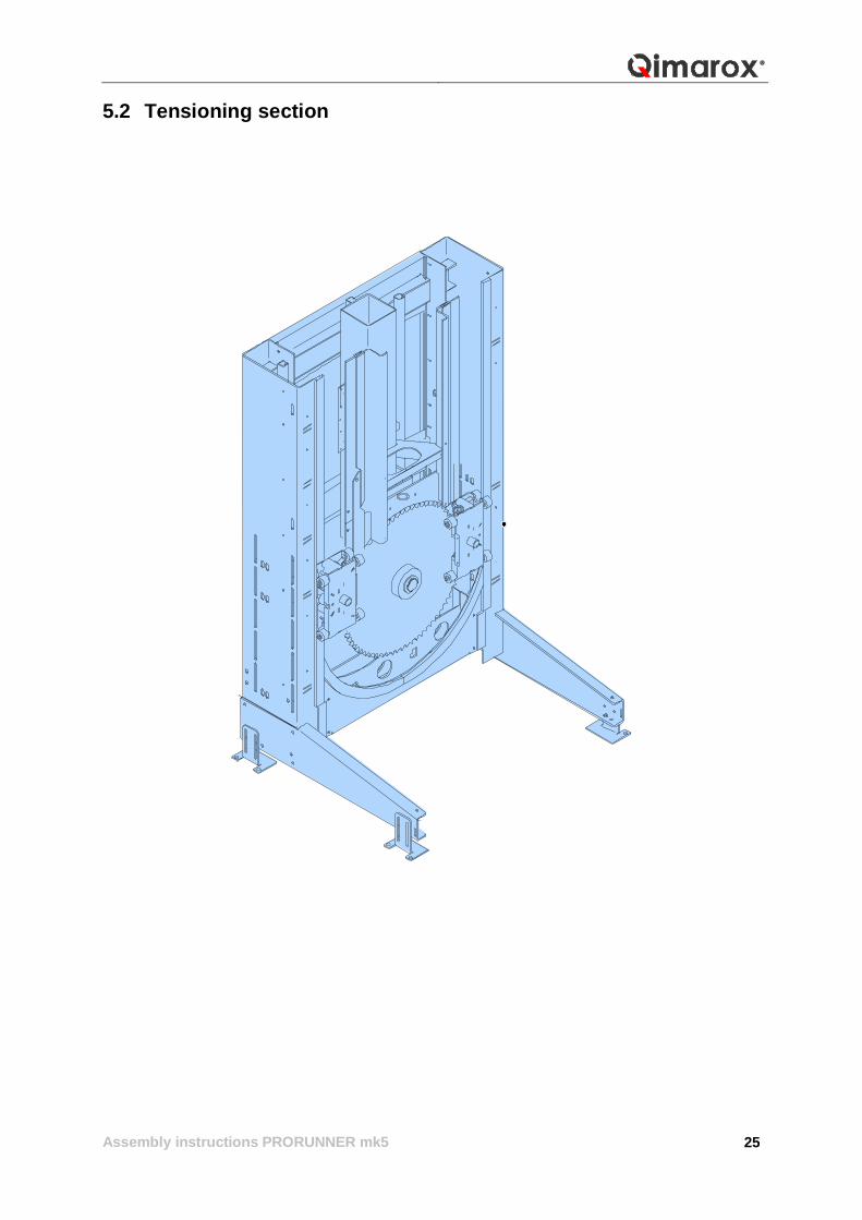
5.2 Tensioning section

Assembly instructions PRORUNNER mk5
26
5.2.1 Lower section parts
For the part numbers, see Section 6.3
Fit the mountings and panels at a later stage.
Optional Optional Optional
Optional Optional
Assembly instructions PRORUNNER mk5
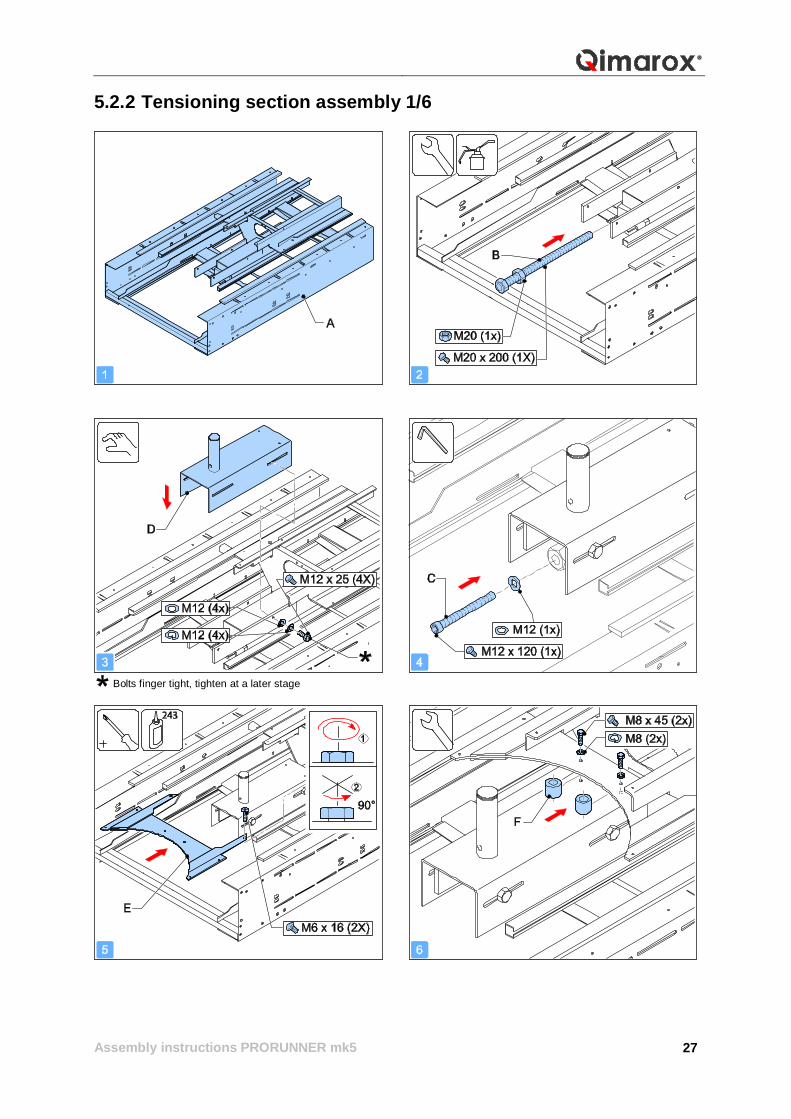
27
5.2.2 Tensioning section assembly 1/6
Bolts finger tight, tighten at a later stage
Assembly instructions PRORUNNER mk5
28
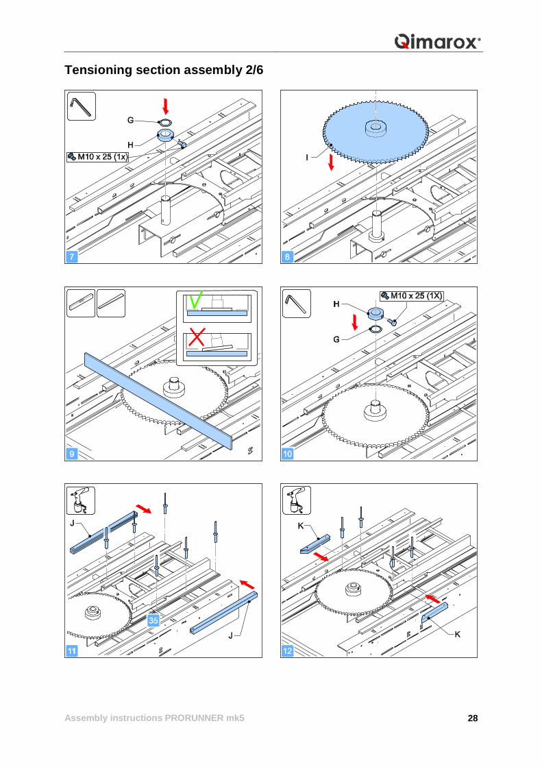
Tensioning section assembly 2/6
Assembly instructions PRORUNNER mk5
29
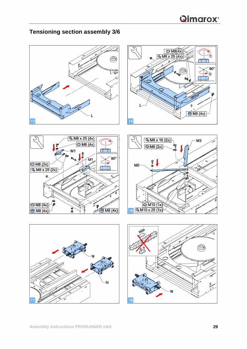
Tensioning section assembly 3/6
Assembly instructions PRORUNNER mk5
30
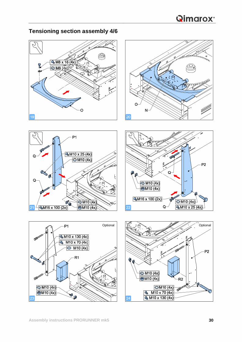
Tensioning section assembly 4/6
OptionalOptional
Assembly instructions PRORUNNER mk5
31
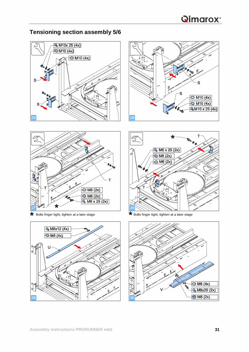
Tensioning section assembly 5/6
Bolts finger tight, tighten at a later stage Bolts finger tight, tighten at a later stage
Assembly instructions PRORUNNER mk5
32
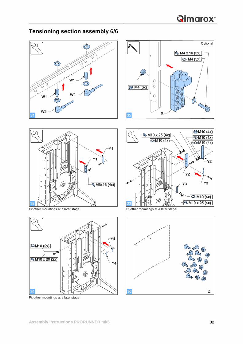
Tensioning section assembly 6/6
Fit other mountings at a later stage Fit other mountings at a later stage
Fit other mountings at a later stage
Optional
Assembly instructions PRORUNNER mk5
33
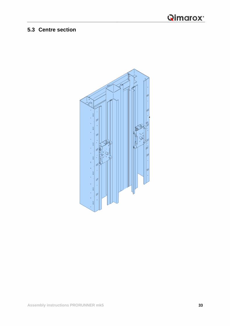
5.3 Centre section
Assembly instructions PRORUNNER mk5
34
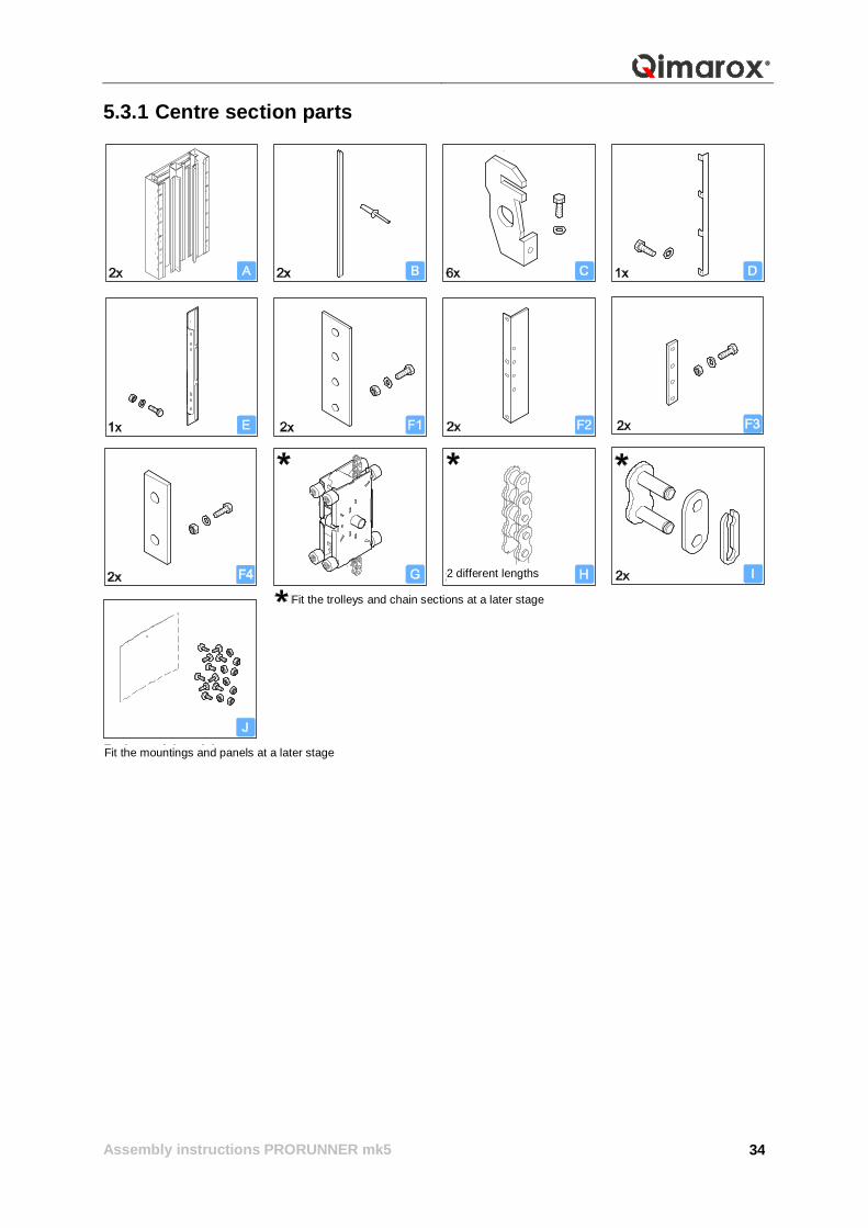
5.3.1 Centre section parts
Fit the mountings and panels at a later stage
2 different lengths
Fit the trolleys and chain sections at a later stage
Assembly instructions PRORUNNER mk5
35
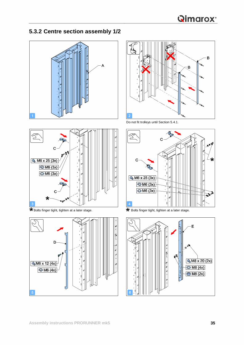
5.3.2 Centre section assembly 1/2
Do not fit trolleys until Section 5.4.1.
Bolts finger tight, tighten at a later stage. Bolts finger tight, tighten at a later stage.
Assembly instructions PRORUNNER mk5
36
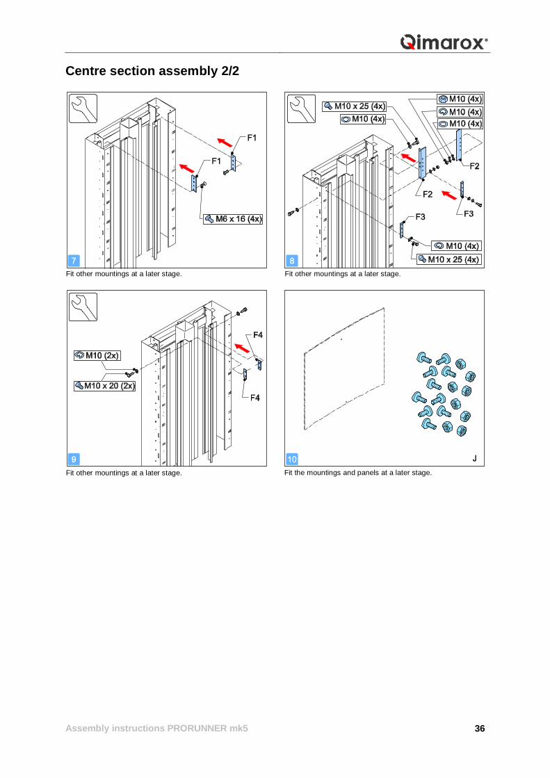
Centre section assembly 2/2
Fit other mountings at a later stage. Fit other mountings at a later stage.
Fit other mountings at a later stage. Fit the mountings and panels at a later stage.
Assembly instructions PRORUNNER mk5
37
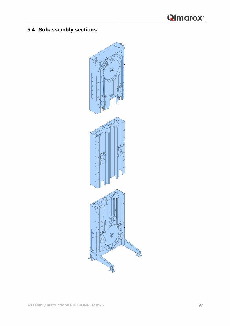
5.4 Subassembly sections
Assembly instructions PRORUNNER mk5
38
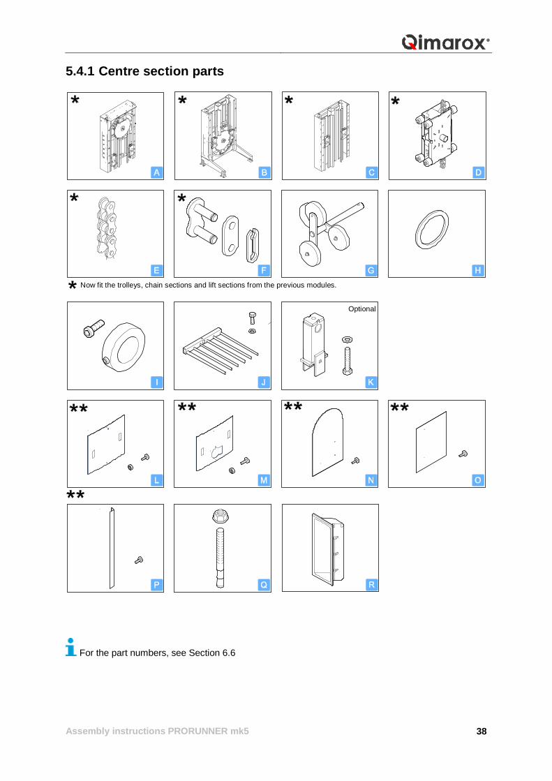
5.4.1 Centre section parts
For the part numbers, see Section 6.6
Optional
Now fit the trolleys, chain sections and lift sections from the previous modules.
Assembly instructions PRORUNNER mk5
39
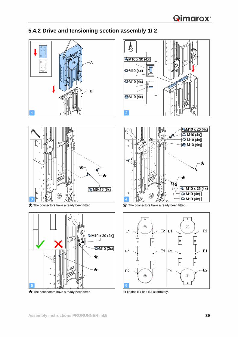
5.4.2 Drive and tensioning section assembly 1/ 2
The connectors have already been fitted. The connectors have already been fitted.
The connectors have already been fitted. Fit chains E1 and E2 alternately.
Assembly instructions PRORUNNER mk5
40
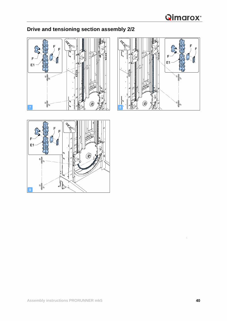
Drive and tensioning section assembly 2/2
Assembly instructions PRORUNNER mk5
41
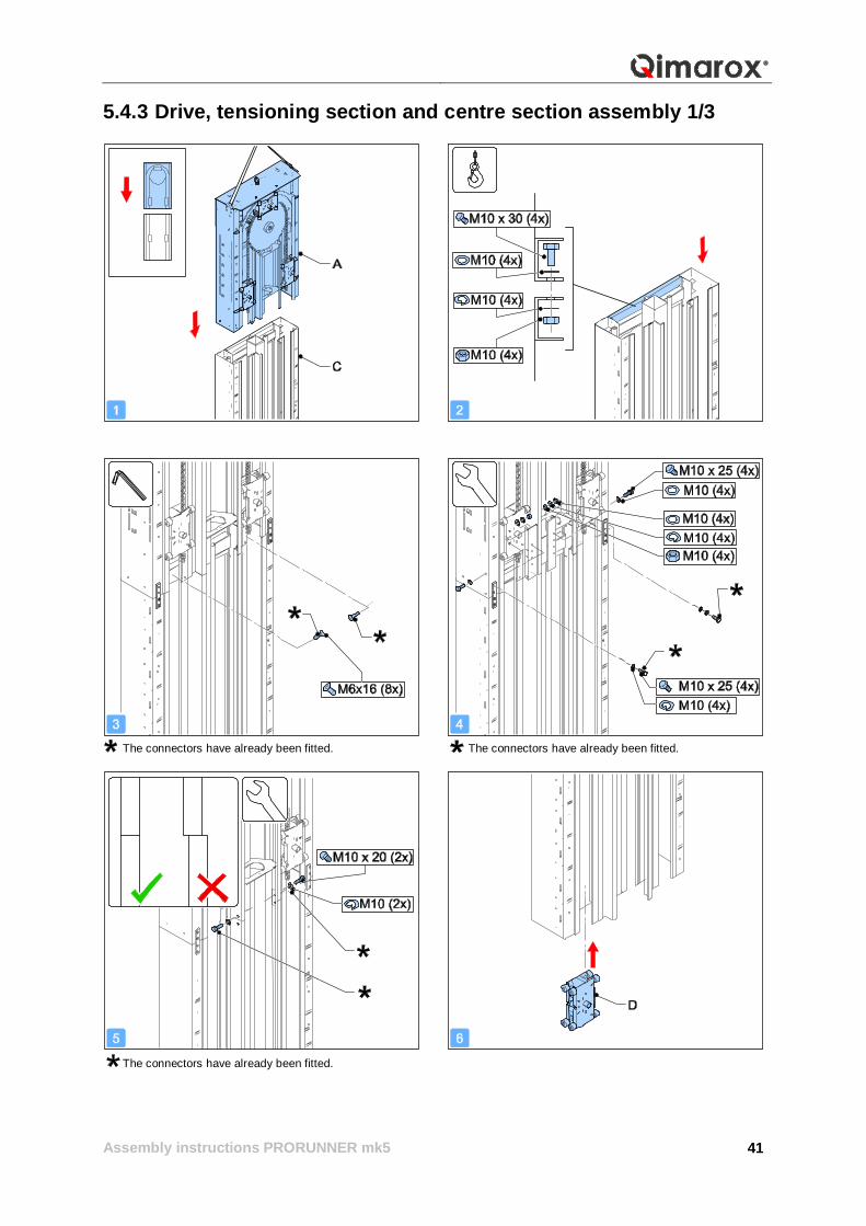
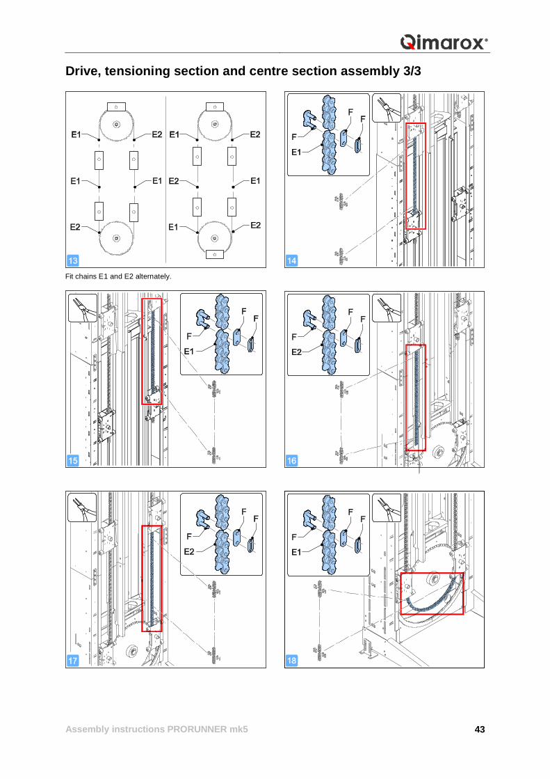
5.4.3 Drive, tensioning section and centre section assembly 1/3
The connectors have already been fitted. The connectors have already been fitted.
The connectors have already been fitted.
Assembly instructions PRORUNNER mk5
42
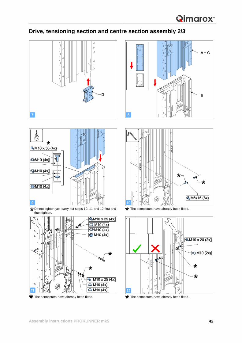
Drive, tensioning section and centre section assembly 2/3
Do not tighten yet; carry out steps 10, 11 and 12 first and then tighten.
The connectors have already been fitted.
The connectors have already been fitted. The connectors have already been fitted.
Assembly instructions PRORUNNER mk5
43
Drive, tensioning section and centre section assembly 3/3
Fit chains E1 and E2 alternately.
Assembly instructions PRORUNNER mk5
44
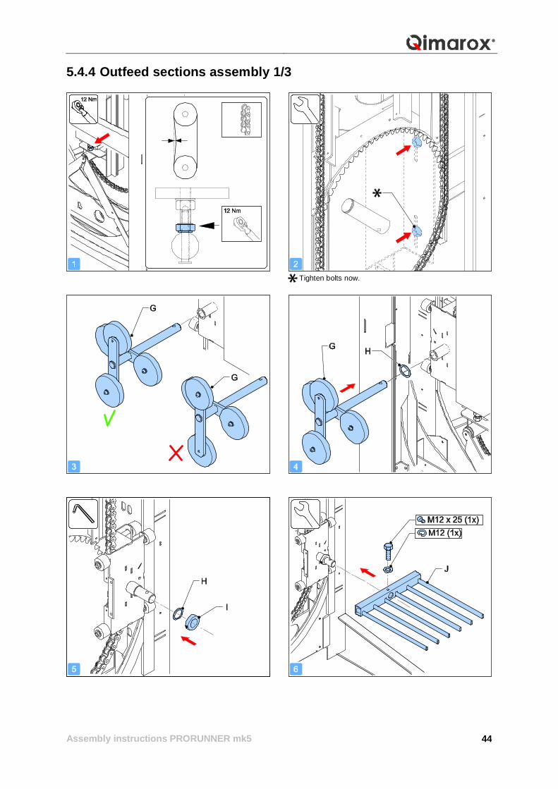
5.4.4 Outfeed sections assembly 1/3
Tighten bolts now.
Assembly instructions PRORUNNER mk5
45
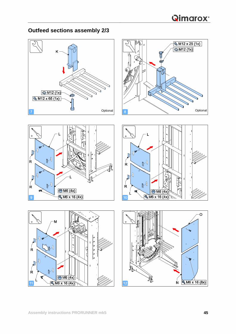
Outfeed sections assembly 2/3
Optional Optional
Assembly instructions PRORUNNER mk5
46
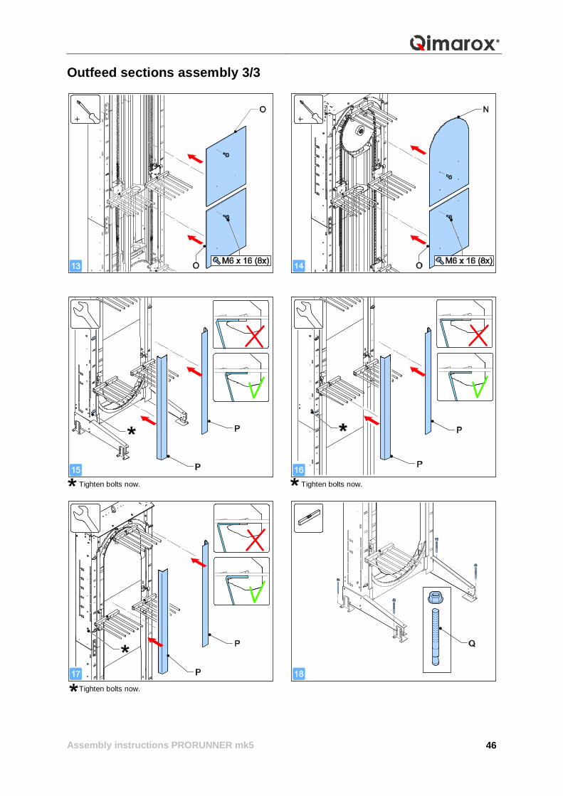
Outfeed sections assembly 3/3
Tighten bolts now. Tighten bolts now.
Tighten bolts now.
Assembly instructions PRORUNNER mk5
47
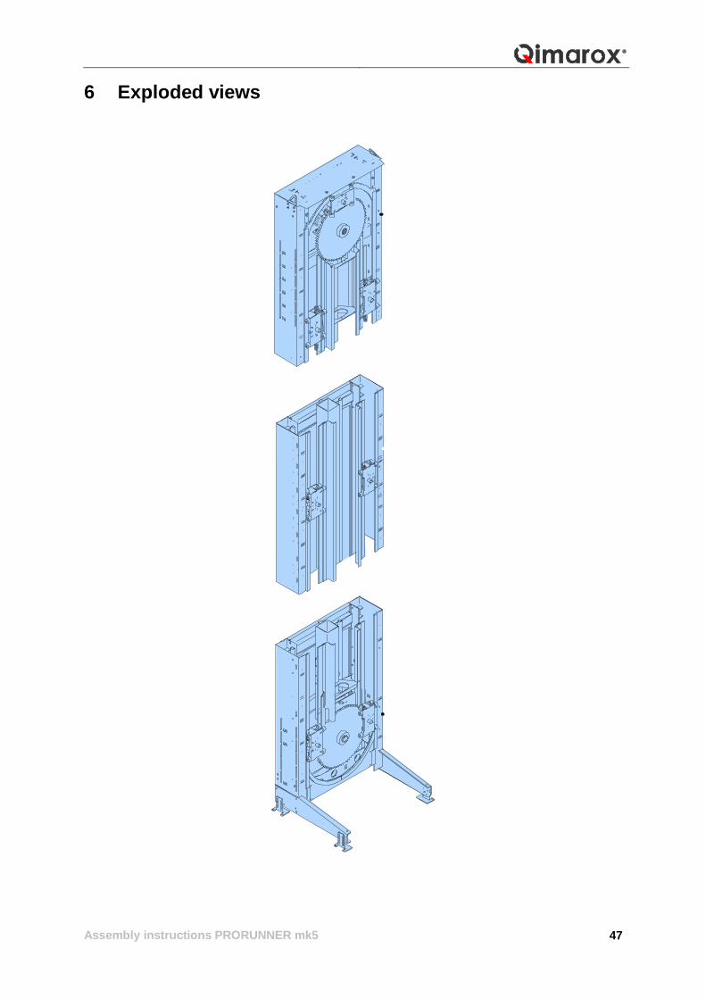
6 Exploded views
Assembly instructions PRORUNNER mk5
48
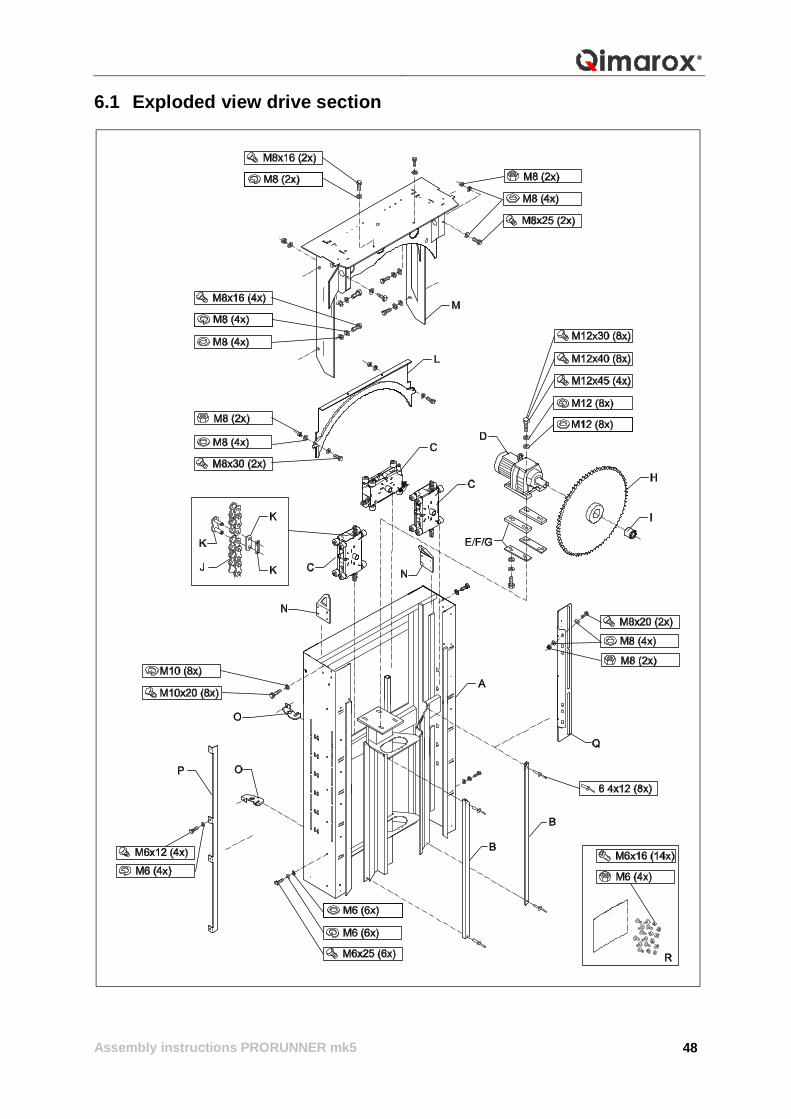
6.1 Exploded view drive section
Assembly instructions PRORUNNER mk5
49
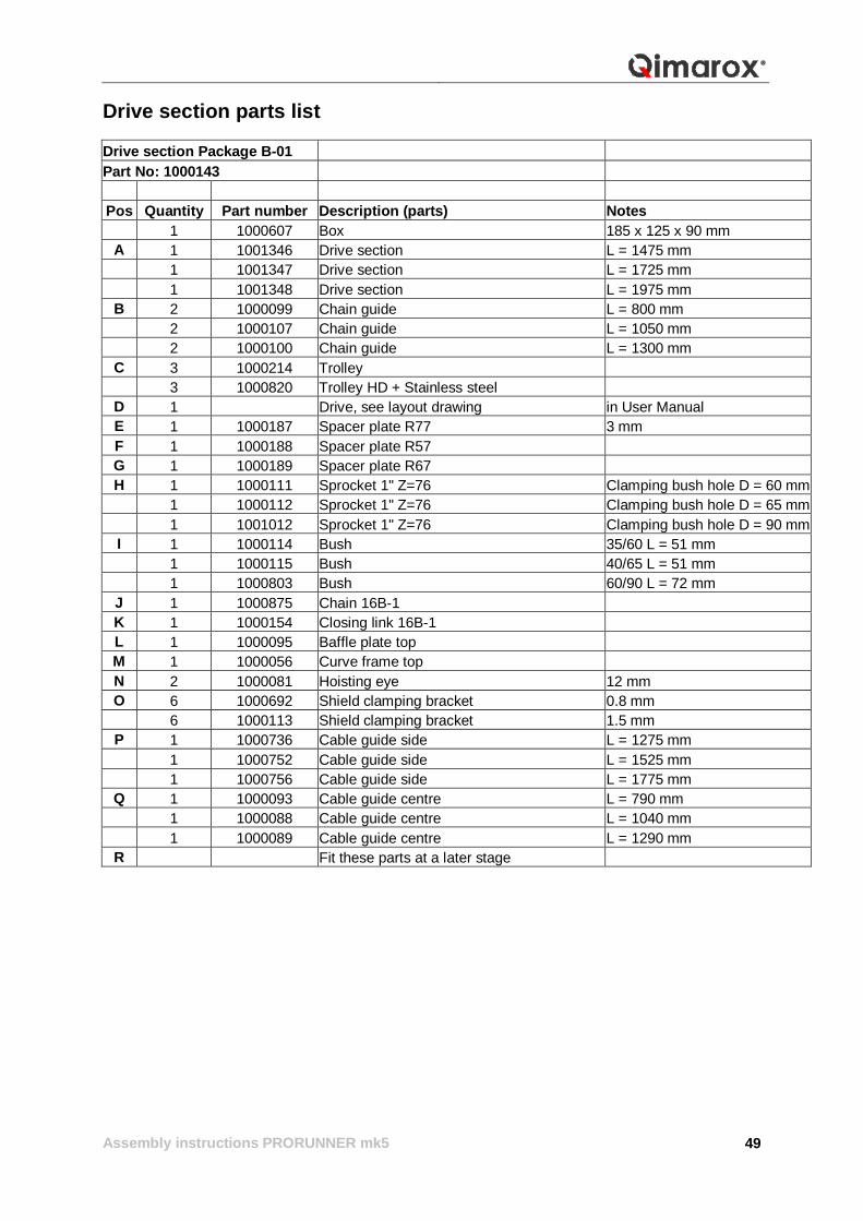
Drive section parts list Drive section Package B-01 Part No: 1000143
Pos Quantity Part number Description (parts) Notes
1 1000607 Box 185 x 125 x 90 mm A 1 1001346 Drive section L = 1475 mm 1 1001347 Drive section L = 1725 mm 1 1001348 Drive section L = 1975 mm
B 2 1000099 Chain guide L = 800 mm 2 1000107 Chain guide L = 1050 mm 2 1000100 Chain guide L = 1300 mm
C 3 1000214 Trolley 3 1000820 Trolley HD + Stainless steel
D 1 Drive, see layout drawing in User Manual E 1 1000187 Spacer plate R77 3 mm F 1 1000188 Spacer plate R57 G 1 1000189 Spacer plate R67 H 1 1000111 Sprocket 1" Z=76 Clamping bush hole D = 60 mm 1 1000112 Sprocket 1" Z=76 Clamping bush hole D = 65 mm 1 1001012 Sprocket 1" Z=76 Clamping bush hole D = 90 mm I 1 1000114 Bush 35/60 L = 51 mm 1 1000115 Bush 40/65 L = 51 mm 1 1000803 Bush 60/90 L = 72 mm
J 1 1000875 Chain 16B-1 K 1 1000154 Closing link 16B-1 L 1 1000095 Baffle plate top M 1 1000056 Curve frame top N 2 1000081 Hoisting eye 12 mm O 6 1000692 Shield clamping bracket 0.8 mm 6 1000113 Shield clamping bracket 1.5 mm
P 1 1000736 Cable guide side L = 1275 mm 1 1000752 Cable guide side L = 1525 mm 1 1000756 Cable guide side L = 1775 mm
Q 1 1000093 Cable guide centre L = 790 mm 1 1000088 Cable guide centre L = 1040 mm 1 1000089 Cable guide centre L = 1290 mm
R Fit these parts at a later stage
Assembly instructions PRORUNNER mk5
50
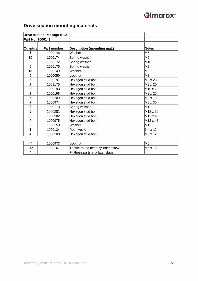
Drive section mounting materials Drive section Package B-02 Part No: 1000143 Quantity Part number Description (mounting mat.) Notes
6 1000148 Washer M6 10 1000174 Spring washer M6 8 1000172 Spring washer M10 6 1000175 Spring washer M8
18 1000149 Washer M8 6 1000050 Locknut M8 6 1000197 Hexagon stud bolt M6 x 25 2 1001175 Hexagon stud bolt M8 x 20 8 1000193 Hexagon stud bolt M10 x 20 2 1000198 Hexagon stud bolt M8 x 25 6 1000209 Hexagon stud bolt M8 x 16 2 1000974 Hexagon stud bolt M8 x 30 8 1000173 Spring washer M12 8 1000201 Hexagon stud bolt M12 x 30 8 1000202 Hexagon stud bolt M12 x 40 4 1000975 Hexagon stud bolt M12 x 45 8 1000150 Washer M12 8 1000134 Pop rivet Al 6.4 x 12 4 1000208 Hexagon stud bolt M6 x 12
4* 1000973 Locknut M6 14* 1000167 Taptite round head cylinder screw M6 x 16 * Fit these parts at a later stage
Assembly instructions PRORUNNER mk5
51
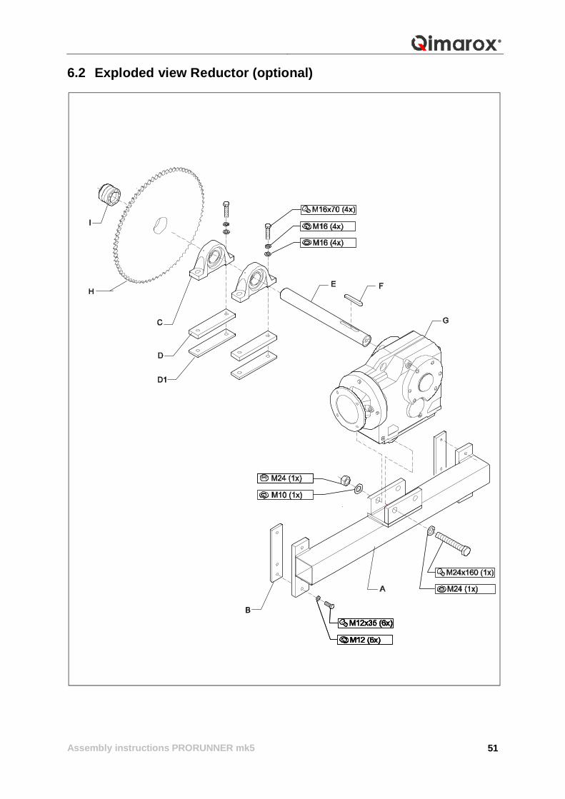
6.2 Exploded view Reductor (optional)
Assembly instructions PRORUNNER mk5
52
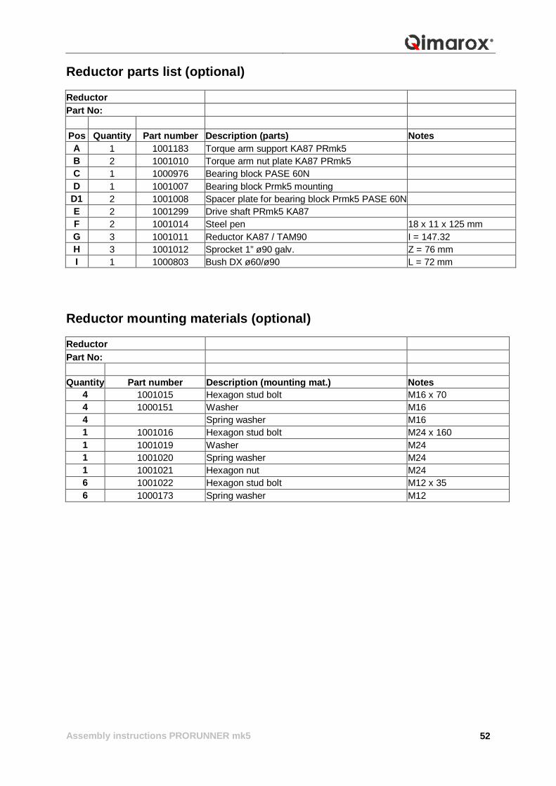
Reductor parts list (optional) Reductor Part No:
Pos Quantity Part number Description (parts) Notes A 1 1001183 Torque arm support KA87 PRmk5 B 2 1001010 Torque arm nut plate KA87 PRmk5 C 1 1000976 Bearing block PASE 60N D 1 1001007 Bearing block Prmk5 mounting
D1 2 1001008 Spacer plate for bearing block Prmk5 PASE 60N E 2 1001299 Drive shaft PRmk5 KA87 F 2 1001014 Steel pen 18 x 11 x 125 mm G 3 1001011 Reductor KA87 / TAM90 I = 147.32 H 3 1001012 Sprocket 1” ø90 galv. Z = 76 mm I 1 1000803 Bush DX ø60/ø90 L = 72 mm
Reductor mounting materials (optional) Reductor Part No: Quantity Part number Description (mounting mat.) Notes
4 1001015 Hexagon stud bolt M16 x 70 4 1000151 Washer M16 4 Spring washer M16 1 1001016 Hexagon stud bolt M24 x 160 1 1001019 Washer M24 1 1001020 Spring washer M24 1 1001021 Hexagon nut M24 6 1001022 Hexagon stud bolt M12 x 35 6 1000173 Spring washer M12
Assembly instructions PRORUNNER mk5
53
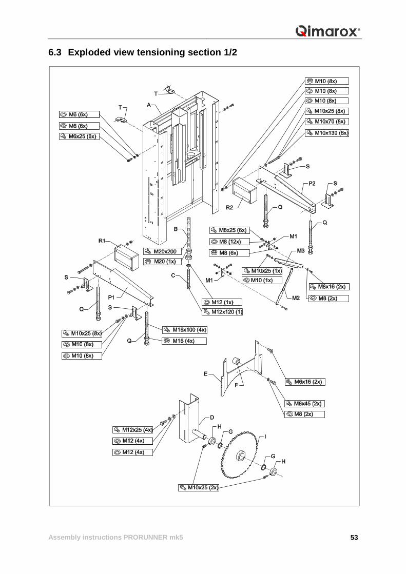
6.3 Exploded view tensioning section 1/2
Assembly instructions PRORUNNER mk5
54
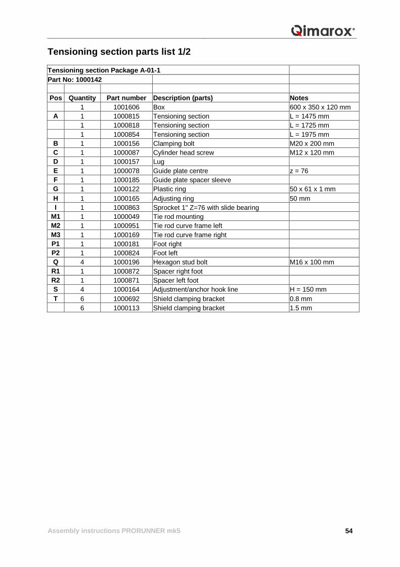
Tensioning section parts list 1/2 Tensioning section Package A-01-1 Part No: 1000142
Pos Quantity Part number Description (parts) Notes
1 1001606 Box 600 x 350 x 120 mm A 1 1000815 Tensioning section L = 1475 mm 1 1000818 Tensioning section L = 1725 mm 1 1000854 Tensioning section L = 1975 mm B 1 1000156 Clamping bolt M20 x 200 mm C 1 1000087 Cylinder head screw M12 x 120 mm D 1 1000157 Lug E 1 1000078 Guide plate centre z = 76 F 1 1000185 Guide plate spacer sleeve G 1 1000122 Plastic ring 50 x 61 x 1 mm H 1 1000165 Adjusting ring 50 mm I 1 1000863 Sprocket 1" Z=76 with slide bearing
M1 1 1000049 Tie rod mounting M2 1 1000951 Tie rod curve frame left M3 1 1000169 Tie rod curve frame right P1 1 1000181 Foot right P2 1 1000824 Foot left Q 4 1000196 Hexagon stud bolt M16 x 100 mm R1 1 1000872 Spacer right foot R2 1 1000871 Spacer left foot S 4 1000164 Adjustment/anchor hook line H = 150 mm T 6 1000692 Shield clamping bracket 0.8 mm 6 1000113 Shield clamping bracket 1.5 mm
Assembly instructions PRORUNNER mk5
55
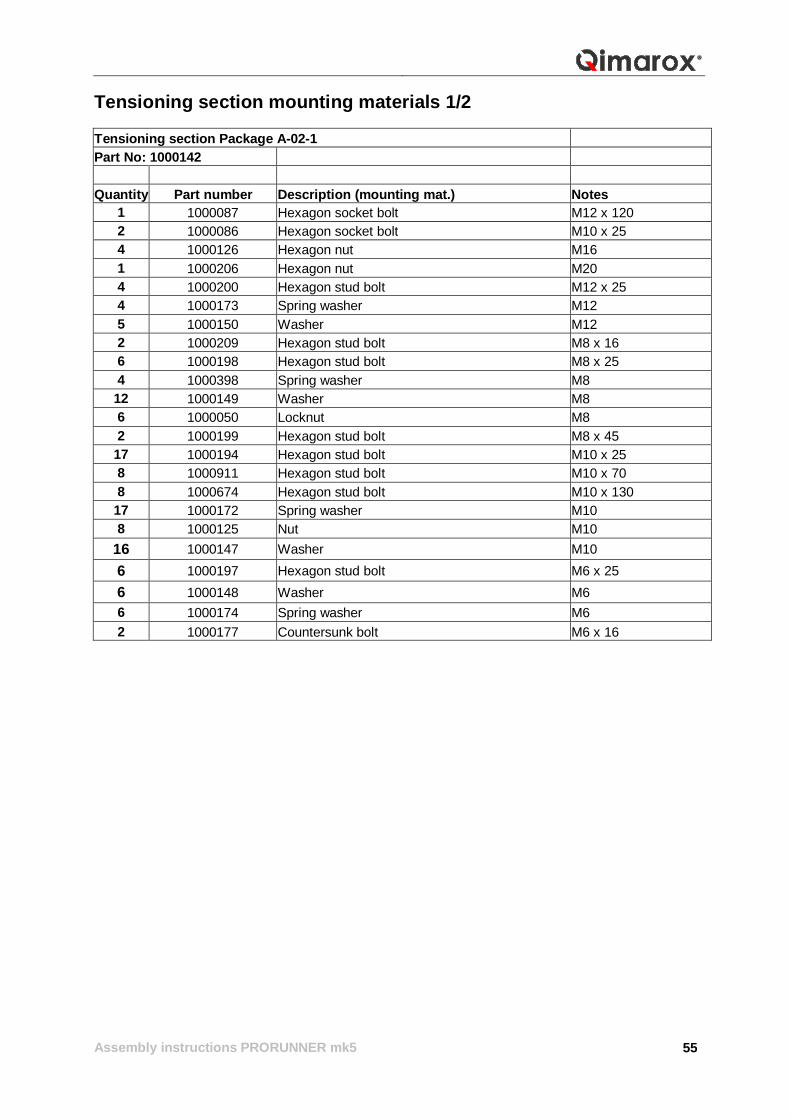
Tensioning section mounting materials 1/2 Tensioning section Package A-02-1 Part No: 1000142 Quantity Part number Description (mounting mat.) Notes
1 1000087 Hexagon socket bolt M12 x 120 2 1000086 Hexagon socket bolt M10 x 25 4 1000126 Hexagon nut M16 1 1000206 Hexagon nut M20 4 1000200 Hexagon stud bolt M12 x 25 4 1000173 Spring washer M12 5 1000150 Washer M12 2 1000209 Hexagon stud bolt M8 x 16 6 1000198 Hexagon stud bolt M8 x 25 4 1000398 Spring washer M8
12 1000149 Washer M8 6 1000050 Locknut M8 2 1000199 Hexagon stud bolt M8 x 45
17 1000194 Hexagon stud bolt M10 x 25 8 1000911 Hexagon stud bolt M10 x 70 8 1000674 Hexagon stud bolt M10 x 130
17 1000172 Spring washer M10 8 1000125 Nut M10
16 1000147 Washer M10 6 1000197 Hexagon stud bolt M6 x 25 6 1000148 Washer M6 6 1000174 Spring washer M6 2 1000177 Countersunk bolt M6 x 16
Assembly instructions PRORUNNER mk5
56
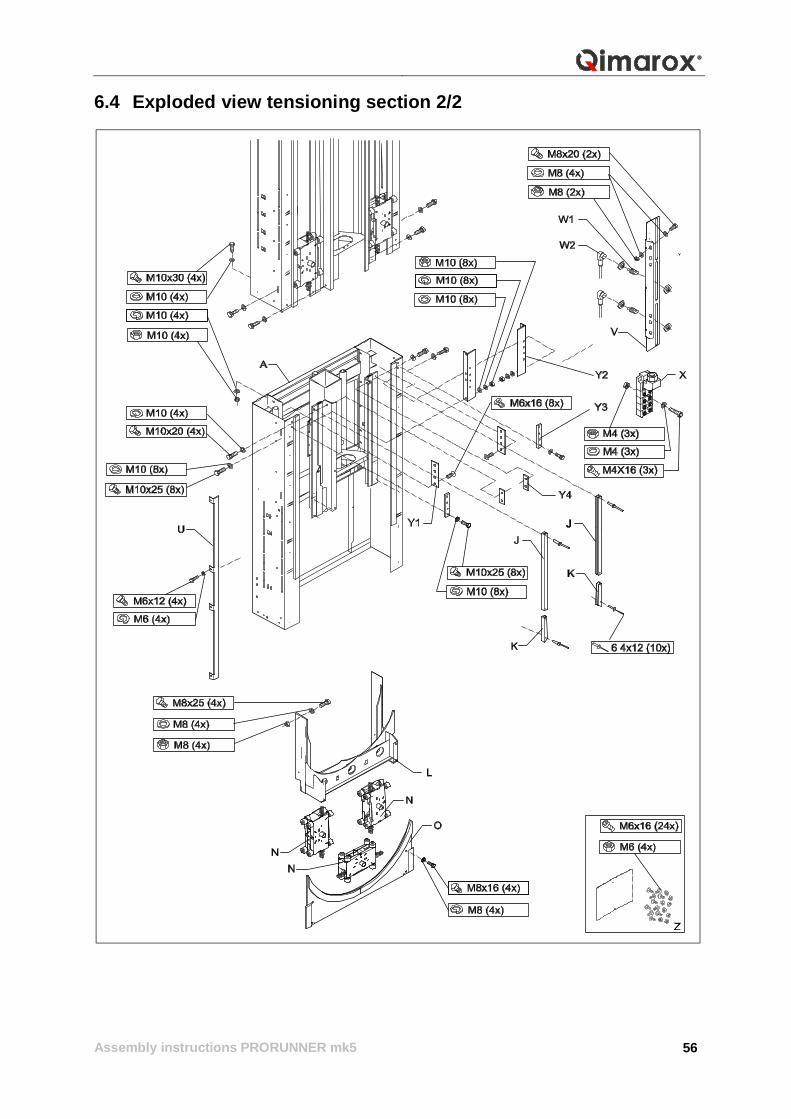
6.4 Exploded view tensioning section 2/2
Assembly instructions PRORUNNER mk5
57
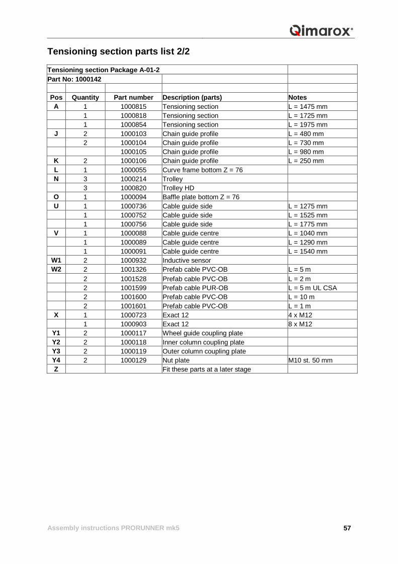
Tensioning section parts list 2/2 Tensioning section Package A-01-2 Part No: 1000142
Pos Quantity Part number Description (parts) Notes A 1 1000815 Tensioning section L = 1475 mm 1 1000818 Tensioning section L = 1725 mm 1 1000854 Tensioning section L = 1975 mm
J 2 1000103 Chain guide profile L = 480 mm 2 1000104 Chain guide profile L = 730 mm 1000105 Chain guide profile L = 980 mm
K 2 1000106 Chain guide profile L = 250 mm L 1 1000055 Curve frame bottom Z = 76 N 3 1000214 Trolley 3 1000820 Trolley HD
O 1 1000094 Baffle plate bottom Z = 76 U 1 1000736 Cable guide side L = 1275 mm 1 1000752 Cable guide side L = 1525 mm 1 1000756 Cable guide side L = 1775 mm
V 1 1000088 Cable guide centre L = 1040 mm 1 1000089 Cable guide centre L = 1290 mm 1 1000091 Cable guide centre L = 1540 mm
W1 2 1000932 Inductive sensor W2 2 1001326 Prefab cable PVC-OB L = 5 m
2 1001528 Prefab cable PVC-OB L = 2 m 2 1001599 Prefab cable PUR-OB L = 5 m UL CSA 2 1001600 Prefab cable PVC-OB L = 10 m 2 1001601 Prefab cable PVC-OB L = 1 m
X 1 1000723 Exact 12 4 x M12 1 1000903 Exact 12 8 x M12
Y1 2 1000117 Wheel guide coupling plate Y2 2 1000118 Inner column coupling plate Y3 2 1000119 Outer column coupling plate Y4 2 1000129 Nut plate M10 st. 50 mm Z Fit these parts at a later stage
Assembly instructions PRORUNNER mk5
58
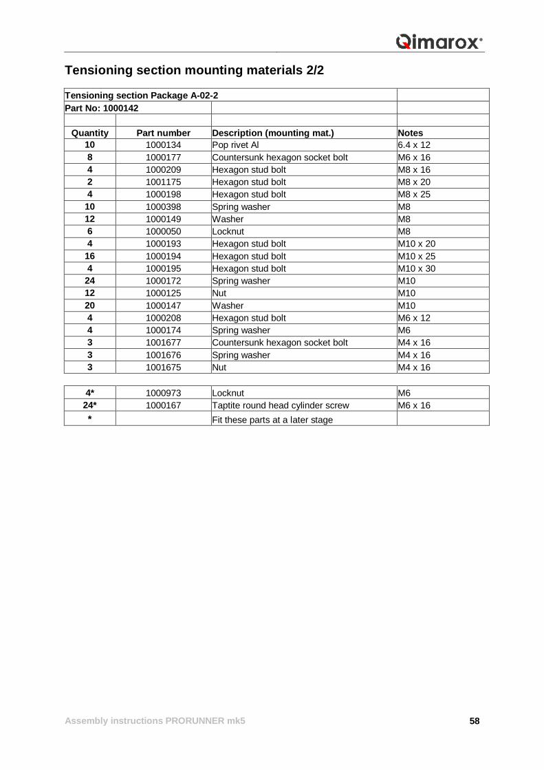
Tensioning section mounting materials 2/2 Tensioning section Package A-02-2 Part No: 1000142
Quantity Part number Description (mounting mat.) Notes 10 1000134 Pop rivet Al 6.4 x 12 8 1000177 Countersunk hexagon socket bolt M6 x 16 4 1000209 Hexagon stud bolt M8 x 16 2 1001175 Hexagon stud bolt M8 x 20 4 1000198 Hexagon stud bolt M8 x 25
10 1000398 Spring washer M8 12 1000149 Washer M8 6 1000050 Locknut M8 4 1000193 Hexagon stud bolt M10 x 20
16 1000194 Hexagon stud bolt M10 x 25 4 1000195 Hexagon stud bolt M10 x 30
24 1000172 Spring washer M10 12 1000125 Nut M10 20 1000147 Washer M10 4 1000208 Hexagon stud bolt M6 x 12 4 1000174 Spring washer M6 3 1001677 Countersunk hexagon socket bolt M4 x 16 3 1001676 Spring washer M4 x 16 3 1001675 Nut M4 x 16
4* 1000973 Locknut M6
24* 1000167 Taptite round head cylinder screw M6 x 16 * Fit these parts at a later stage
Assembly instructions PRORUNNER mk5
59
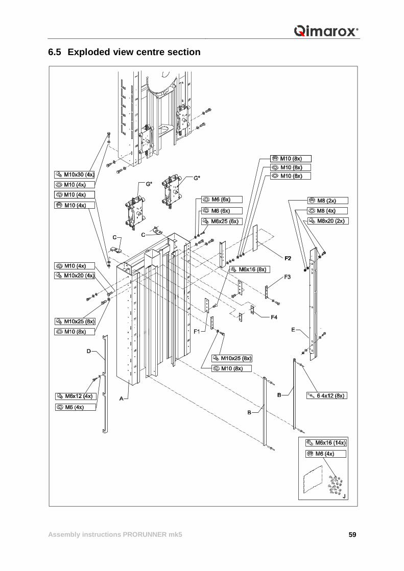
6.5 Exploded view centre section
Assembly instructions PRORUNNER mk5
60
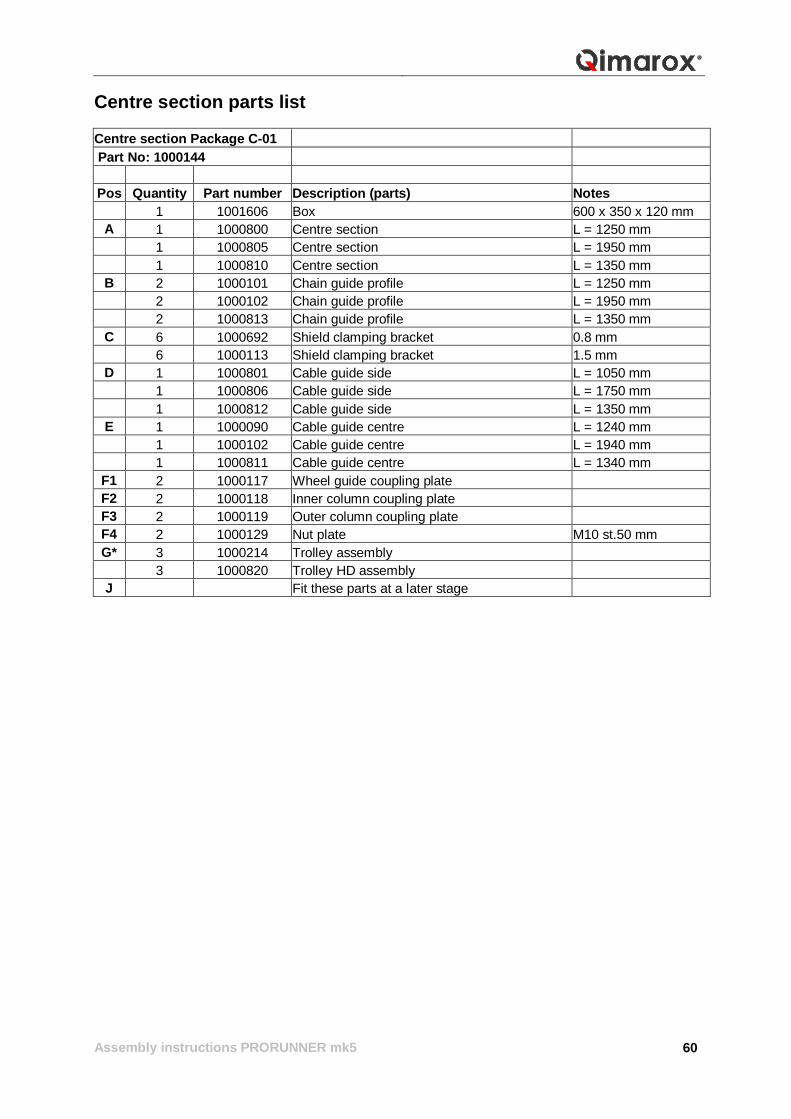
Centre section parts list Centre section Package C-01 Part No: 1000144
Pos Quantity Part number Description (parts) Notes
1 1001606 Box 600 x 350 x 120 mm A 1 1000800 Centre section L = 1250 mm 1 1000805 Centre section L = 1950 mm 1 1000810 Centre section L = 1350 mm
B 2 1000101 Chain guide profile L = 1250 mm 2 1000102 Chain guide profile L = 1950 mm 2 1000813 Chain guide profile L = 1350 mm
C 6 1000692 Shield clamping bracket 0.8 mm 6 1000113 Shield clamping bracket 1.5 mm
D 1 1000801 Cable guide side L = 1050 mm 1 1000806 Cable guide side L = 1750 mm 1 1000812 Cable guide side L = 1350 mm
E 1 1000090 Cable guide centre L = 1240 mm 1 1000102 Cable guide centre L = 1940 mm 1 1000811 Cable guide centre L = 1340 mm
F1 2 1000117 Wheel guide coupling plate F2 2 1000118 Inner column coupling plate F3 2 1000119 Outer column coupling plate F4 2 1000129 Nut plate M10 st.50 mm G* 3 1000214 Trolley assembly
3 1000820 Trolley HD assembly J Fit these parts at a later stage
Assembly instructions PRORUNNER mk5
61
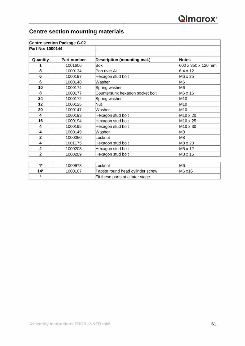
Centre section mounting materials Centre section Package C-02 Part No: 1000144
Quantity Part number Description (mounting mat.) Notes 1 1001606 Box 600 x 350 x 120 mm 8 1000134 Pop rivet Al 6.4 x 12 6 1000197 Hexagon stud bolt M6 x 25 6 1000148 Washer M6
10 1000174 Spring washer M6 8 1000177 Countersunk hexagon socket bolt M6 x 16
24 1000172 Spring washer M10 12 1000125 Nut M10 20 1000147 Washer M10 4 1000193 Hexagon stud bolt M10 x 20
16 1000194 Hexagon stud bolt M10 x 25 4 1000195 Hexagon stud bolt M10 x 30 4 1000149 Washer M8 2 1000050 Locknut M8 4 1001175 Hexagon stud bolt M8 x 20 4 1000208 Hexagon stud bolt M6 x 12 2 1000209 Hexagon stud bolt M8 x 16
4* 1000973 Locknut M6 14* 1000167 Taptite round head cylinder screw M6 x16 * Fit these parts at a later stage
Assembly instructions PRORUNNER mk5
62
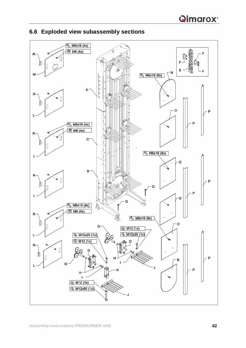
6.6 Exploded view subassembly sections
Assembly instructions PRORUNNER mk5
63
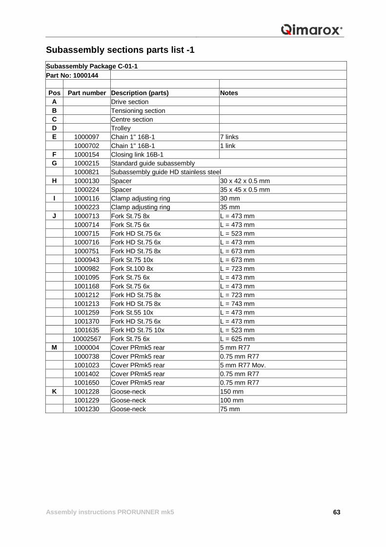
Subassembly sections parts list -1 Subassembly Package C-01-1 Part No: 1000144
Pos Part number Description (parts) Notes A Drive section B Tensioning section C Centre section D Trolley E 1000097 Chain 1" 16B-1 7 links 1000702 Chain 1" 16B-1 1 link
F 1000154 Closing link 16B-1 G 1000215 Standard guide subassembly 1000821 Subassembly guide HD stainless steel
H 1000130 Spacer 30 x 42 x 0.5 mm 1000224 Spacer 35 x 45 x 0.5 mm I 1000116 Clamp adjusting ring 30 mm 1000223 Clamp adjusting ring 35 mm J 1000713 Fork St.75 8x L = 473 mm 1000714 Fork St.75 6x L = 473 mm 1000715 Fork HD St.75 6x L = 523 mm 1000716 Fork HD St.75 6x L = 473 mm 1000751 Fork HD St.75 8x L = 673 mm 1000943 Fork St.75 10x L = 673 mm 1000982 Fork St.100 8x L = 723 mm 1001095 Fork St.75 6x L = 473 mm 1001168 Fork St.75 6x L = 473 mm 1001212 Fork HD St.75 8x L = 723 mm 1001213 Fork HD St.75 8x L = 743 mm 1001259 Fork St.55 10x L = 473 mm 1001370 Fork HD St.75 6x L = 473 mm 1001635 Fork HD St.75 10x L = 523 mm 10002567 Fork St.75 6x L = 625 mm
M 1000004 Cover PRmk5 rear 5 mm R77 1000738 Cover PRmk5 rear 0.75 mm R77 1001023 Cover PRmk5 rear 5 mm R77 Mov. 1001402 Cover PRmk5 rear 0.75 mm R77 1001650 Cover PRmk5 rear 0.75 mm R77 K 1001228 Goose-neck 150 mm 1001229 Goose-neck 100 mm 1001230 Goose-neck 75 mm
Assembly instructions PRORUNNER mk5
64
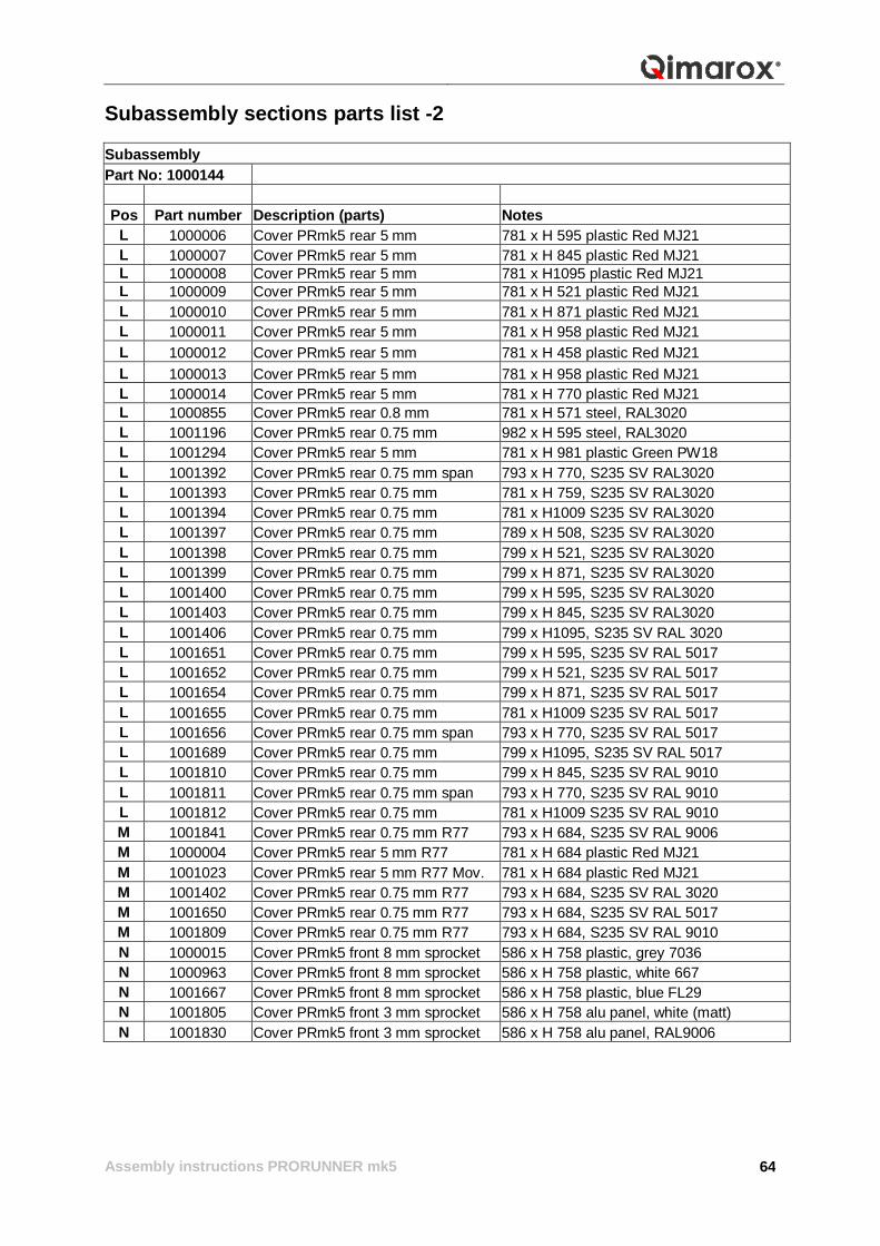
Subassembly sections parts list -2 Subassembly Part No: 1000144
Pos Part number Description (parts) Notes
L 1000006 Cover PRmk5 rear 5 mm 781 x H 595 plastic Red MJ21 L 1000007 Cover PRmk5 rear 5 mm 781 x H 845 plastic Red MJ21 L 1000008 Cover PRmk5 rear 5 mm 781 x H1095 plastic Red MJ21 L 1000009 Cover PRmk5 rear 5 mm 781 x H 521 plastic Red MJ21 L 1000010 Cover PRmk5 rear 5 mm 781 x H 871 plastic Red MJ21 L 1000011 Cover PRmk5 rear 5 mm 781 x H 958 plastic Red MJ21 L 1000012 Cover PRmk5 rear 5 mm 781 x H 458 plastic Red MJ21 L 1000013 Cover PRmk5 rear 5 mm 781 x H 958 plastic Red MJ21 L 1000014 Cover PRmk5 rear 5 mm 781 x H 770 plastic Red MJ21 L 1000855 Cover PRmk5 rear 0.8 mm 781 x H 571 steel, RAL3020 L 1001196 Cover PRmk5 rear 0.75 mm 982 x H 595 steel, RAL3020 L 1001294 Cover PRmk5 rear 5 mm 781 x H 981 plastic Green PW18 L 1001392 Cover PRmk5 rear 0.75 mm span 793 x H 770, S235 SV RAL3020 L 1001393 Cover PRmk5 rear 0.75 mm 781 x H 759, S235 SV RAL3020 L 1001394 Cover PRmk5 rear 0.75 mm 781 x H1009 S235 SV RAL3020 L 1001397 Cover PRmk5 rear 0.75 mm 789 x H 508, S235 SV RAL3020 L 1001398 Cover PRmk5 rear 0.75 mm 799 x H 521, S235 SV RAL3020 L 1001399 Cover PRmk5 rear 0.75 mm 799 x H 871, S235 SV RAL3020 L 1001400 Cover PRmk5 rear 0.75 mm 799 x H 595, S235 SV RAL3020 L 1001403 Cover PRmk5 rear 0.75 mm 799 x H 845, S235 SV RAL3020 L 1001406 Cover PRmk5 rear 0.75 mm 799 x H1095, S235 SV RAL 3020 L 1001651 Cover PRmk5 rear 0.75 mm 799 x H 595, S235 SV RAL 5017 L 1001652 Cover PRmk5 rear 0.75 mm 799 x H 521, S235 SV RAL 5017 L 1001654 Cover PRmk5 rear 0.75 mm 799 x H 871, S235 SV RAL 5017 L 1001655 Cover PRmk5 rear 0.75 mm 781 x H1009 S235 SV RAL 5017 L 1001656 Cover PRmk5 rear 0.75 mm span 793 x H 770, S235 SV RAL 5017 L 1001689 Cover PRmk5 rear 0.75 mm 799 x H1095, S235 SV RAL 5017 L 1001810 Cover PRmk5 rear 0.75 mm 799 x H 845, S235 SV RAL 9010 L 1001811 Cover PRmk5 rear 0.75 mm span 793 x H 770, S235 SV RAL 9010 L 1001812 Cover PRmk5 rear 0.75 mm 781 x H1009 S235 SV RAL 9010 M 1001841 Cover PRmk5 rear 0.75 mm R77 793 x H 684, S235 SV RAL 9006 M 1000004 Cover PRmk5 rear 5 mm R77 781 x H 684 plastic Red MJ21 M 1001023 Cover PRmk5 rear 5 mm R77 Mov. 781 x H 684 plastic Red MJ21 M 1001402 Cover PRmk5 rear 0.75 mm R77 793 x H 684, S235 SV RAL 3020 M 1001650 Cover PRmk5 rear 0.75 mm R77 793 x H 684, S235 SV RAL 5017 M 1001809 Cover PRmk5 rear 0.75 mm R77 793 x H 684, S235 SV RAL 9010 N 1000015 Cover PRmk5 front 8 mm sprocket 586 x H 758 plastic, grey 7036 N 1000963 Cover PRmk5 front 8 mm sprocket 586 x H 758 plastic, white 667 N 1001667 Cover PRmk5 front 8 mm sprocket 586 x H 758 plastic, blue FL29 N 1001805 Cover PRmk5 front 3 mm sprocket 586 x H 758 alu panel, white (matt) N 1001830 Cover PRmk5 front 3 mm sprocket 586 x H 758 alu panel, RAL9006
Assembly instructions PRORUNNER mk5
65
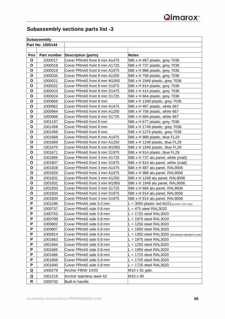
Subassembly sections parts list -3 Subassembly Part No: 1000144
Pos Part number Description (parts) Notes O 1000017 Cover PRmk5 front 8 mm A1475 586 x H 487 plastic, grey 7036 O 1000018 Cover PRmk5 front 8 mm A1725 586 x H 737 plastic, grey 7036 O 1000019 Cover PRmk5 front 8 mm A1975 586 x H 988 plastic, grey 7036 O 1000020 Cover PRmk5 front 8 mm A1250 586 x H 758 plastic, grey 7036 O 1000021 Cover PRmk5 front 8 mm M1950 586 x H 1949 plastic, grey 7036 O 1000022 Cover PRmk5 front 8 mm S1975 586 x H 914 plastic, grey 7036 O 1000023 Cover PRmk5 front 8 mm S1475 586 x H 414 plastic, grey 7036 O 1000024 Cover PRmk5 front 8 mm S1725 586 x H 664 plastic, grey 7036 O 1000856 Cover PRmk5 front 8 mm 586 x H 1349 plastic, grey 7036 O 1000962 Cover PRmk5 front 8 mm A1475 586 x H 487 plastic, white 667 O 1000964 Cover PRmk5 front 8 mm A1250 586 x H 758 plastic, white 667 O 1000966 Cover PRmk5 front 8 mm S1725 586 x H 684 plastic, white 667 O 1001197 Cover PRmk5 front 8 mm 586 x H 677 plastic, grey 7036 O 1001458 Cover PRmk5 front 8 mm 586 x H 1749 plastic, grey 7036 O 1001459 Cover PRmk5 front 8 mm 586 x H 1274 plastic, grey 7036 O 1001668 Cover PRmk5 front 8 mm A1975 586 x H 988 plastic, blue FL29 O 1001669 Cover PRmk5 front 8 mm A1250 586 x H 1249 plastic, blue FL29 O 1001670 Cover PRmk5 front 8 mm M1950 586 x H 1949 plastic, blue FL29 O 1001671 Cover PRmk5 front 8 mm S1975 586 x H 914 plastic, blue FL29 O 1001806 Cover PRmk5 front 3 mm A1725 586 x H 737 alu panel, white (matt) O 1001807 Cover PRmk5 front 3 mm S1975 586 x H 914 alu panel, white (matt) O 1001828 Cover PRmk5 front 3 mm A1475 586 x H 487 alu panel, RAL9006 O 1001829 Cover PRmk5 front 3 mm A1975 586 x H 988 alu panel, RAL9006 O 1001831 Cover PRmk5 front 3 mm A1250 586 x H 1249 alu panel, RAL9006 O 1001832 Cover PRmk5 front 3 mm M1950 586 x H 1949 alu panel, RAL9006 O 1001833 Cover PRmk5 front 3 mm S1725 586 x H 684 alu panel, RAL9006 O 1001834 Cover PRmk5 front 3 mm S1975 586 x H 914 alu panel, RAL9006 O 1001835 Cover PRmk5 front 3 mm S1975 586 x H 914 alu panel, RAL9006 P 1001296 Cover PRmk5 side 5.0 mm L = 3050 plastic red MJ21(OLDER TYPE mk5) P 1000737 Cover PRmk5 side 0.8 mm L = 475 steel RAL3020 P 1000753 Cover PRmk5 side 0.8 mm L = 1725 steel RAL3020 P 1000789 Cover PRmk5 side 0.8 mm L = 1975 steel RAL3020 P 1000802 Cover PRmk5 side 0.8 mm L = 1250 steel RAL3020 P 1000807 Cover PRmk5 side 0.8 mm L = 1950 steel RAL3020 P 1000814 Cover PRmk5 side 0.8 mm L = 1350 steel RAL3020 (shortened standard cover) P 1001663 Cover PRmk5 side 0.8 mm L = 1975 steel RAL3020 P 1001664 Cover PRmk5 side 0.8 mm L = 1250 steel RAL3020 P 1001665 Cover PRmk5 side 0.8 mm L = 1950 steel RAL3020 P 1001666 Cover PRmk5 side 0.8 mm L = 1725 steel RAL3020 P 1001808 Cover PRmk5 side 0.8 mm L = 1725 steel RAL3020 P 1001840 Cover PRmk5 side 0.8 mm L = 1725 steel RAL3020 Q 1000278 Anchor FBNII 10/20 M10 x 81 galv. Q 1001219 Anchor stainless steel A2 M10 x 90 R 1000742 Built-in handle
Assembly instructions PRORUNNER mk5
66
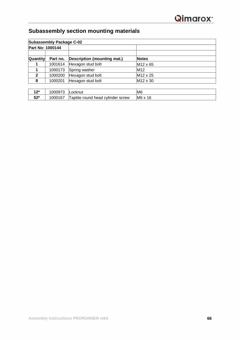
Subassembly section mounting materials Subassembly Package C-02 Part No: 1000144 Quantity Part no. Description (mounting mat.) Notes
1 1001614 Hexagon stud bolt M12 x 65 1 1000173 Spring washer M12 2 1000200 Hexagon stud bolt M12 x 25 8 1000201 Hexagon stud bolt M12 x 30
12* 1000973 Locknut M6 52* 1000167 Taptite round head cylinder screw M6 x 16
Assembly instructions PRORUNNER mk5
67
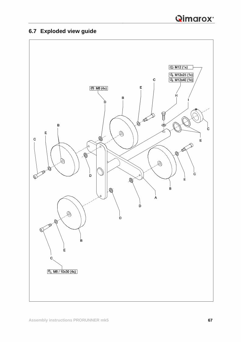
6.7 Exploded view guide
Assembly instructions PRORUNNER mk5
68
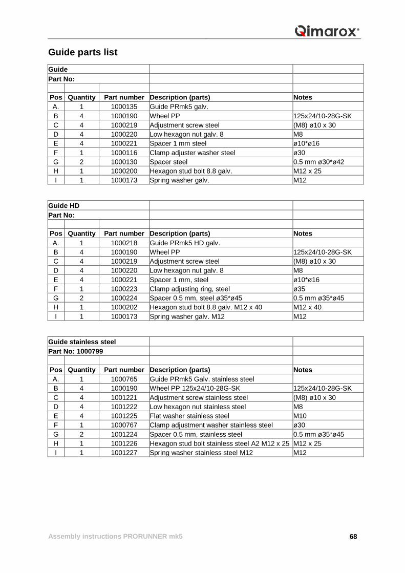
Guide parts list Guide Part No:
Pos Quantity Part number Description (parts) Notes A. 1 1000135 Guide PRmk5 galv. B 4 1000190 Wheel PP 125x24/10-28G-SK C 4 1000219 Adjustment screw steel (M8) ø10 x 30 D 4 1000220 Low hexagon nut galv. 8 M8 E 4 1000221 Spacer 1 mm steel ø10*ø16 F 1 1000116 Clamp adjuster washer steel ø30 G 2 1000130 Spacer steel 0.5 mm ø30*ø42 H 1 1000200 Hexagon stud bolt 8.8 galv. M12 x 25 I 1 1000173 Spring washer galv. M12
Guide HD Part No:
Pos Quantity Part number Description (parts) Notes A. 1 1000218 Guide PRmk5 HD galv. B 4 1000190 Wheel PP 125x24/10-28G-SK C 4 1000219 Adjustment screw steel (M8) ø10 x 30 D 4 1000220 Low hexagon nut galv. 8 M8 E 4 1000221 Spacer 1 mm, steel ø10*ø16 F 1 1000223 Clamp adjusting ring, steel ø35 G 2 1000224 Spacer 0.5 mm, steel ø35*ø45 0.5 mm ø35*ø45 H 1 1000202 Hexagon stud bolt 8.8 galv. M12 x 40 M12 x 40 I 1 1000173 Spring washer galv. M12 M12
Guide stainless steel Part No: 1000799
Pos Quantity Part number Description (parts) Notes A. 1 1000765 Guide PRmk5 Galv. stainless steel B 4 1000190 Wheel PP 125x24/10-28G-SK 125x24/10-28G-SK C 4 1001221 Adjustment screw stainless steel (M8) ø10 x 30 D 4 1001222 Low hexagon nut stainless steel M8 E 4 1001225 Flat washer stainless steel M10 F 1 1000767 Clamp adjustment washer stainless steel ø30 G 2 1001224 Spacer 0.5 mm, stainless steel 0.5 mm ø35*ø45 H 1 1001226 Hexagon stud bolt stainless steel A2 M12 x 25 M12 x 25 I 1 1001227 Spring washer stainless steel M12 M12
Assembly instructions PRORUNNER mk5
69
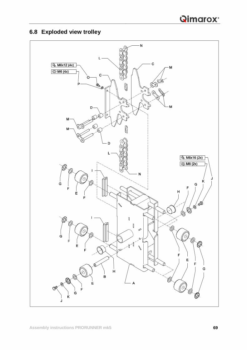
6.8 Exploded view trolley
Assembly instructions PRORUNNER mk5
70
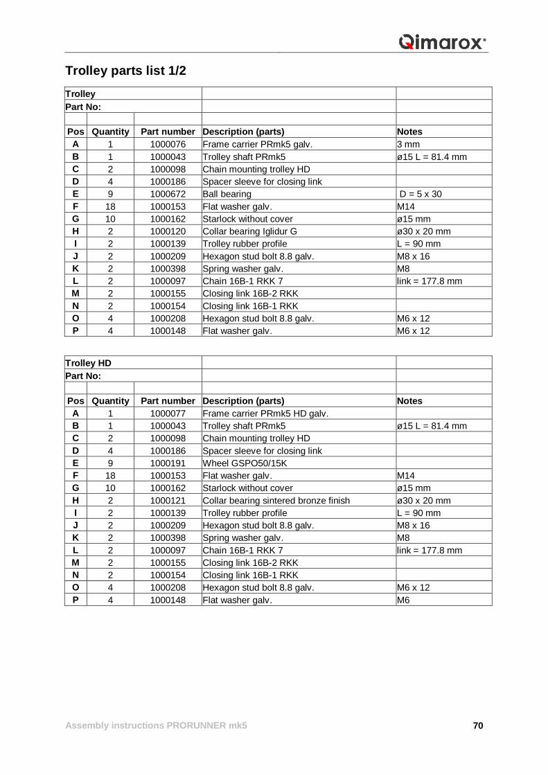
Trolley parts list 1/2 Trolley Part No:
Pos Quantity Part number Description (parts) Notes A 1 1000076 Frame carrier PRmk5 galv. 3 mm B 1 1000043 Trolley shaft PRmk5 ø15 L = 81.4 mm C 2 1000098 Chain mounting trolley HD D 4 1000186 Spacer sleeve for closing link E 9 1000672 Ball bearing D = 5 x 30 F 18 1000153 Flat washer galv. M14 G 10 1000162 Starlock without cover ø15 mm H 2 1000120 Collar bearing Iglidur G ø30 x 20 mm I 2 1000139 Trolley rubber profile L = 90 mm J 2 1000209 Hexagon stud bolt 8.8 galv. M8 x 16 K 2 1000398 Spring washer galv. M8 L 2 1000097 Chain 16B-1 RKK 7 link = 177.8 mm M 2 1000155 Closing link 16B-2 RKK N 2 1000154 Closing link 16B-1 RKK O 4 1000208 Hexagon stud bolt 8.8 galv. M6 x 12 P 4 1000148 Flat washer galv. M6 x 12
Trolley HD Part No:
Pos Quantity Part number Description (parts) Notes A 1 1000077 Frame carrier PRmk5 HD galv. B 1 1000043 Trolley shaft PRmk5 ø15 L = 81.4 mm C 2 1000098 Chain mounting trolley HD D 4 1000186 Spacer sleeve for closing link E 9 1000191 Wheel GSPO50/15K F 18 1000153 Flat washer galv. M14 G 10 1000162 Starlock without cover ø15 mm H 2 1000121 Collar bearing sintered bronze finish ø30 x 20 mm I 2 1000139 Trolley rubber profile L = 90 mm J 2 1000209 Hexagon stud bolt 8.8 galv. M8 x 16 K 2 1000398 Spring washer galv. M8 L 2 1000097 Chain 16B-1 RKK 7 link = 177.8 mm M 2 1000155 Closing link 16B-2 RKK N 2 1000154 Closing link 16B-1 RKK O 4 1000208 Hexagon stud bolt 8.8 galv. M6 x 12 P 4 1000148 Flat washer galv. M6
Assembly instructions PRORUNNER mk5
71
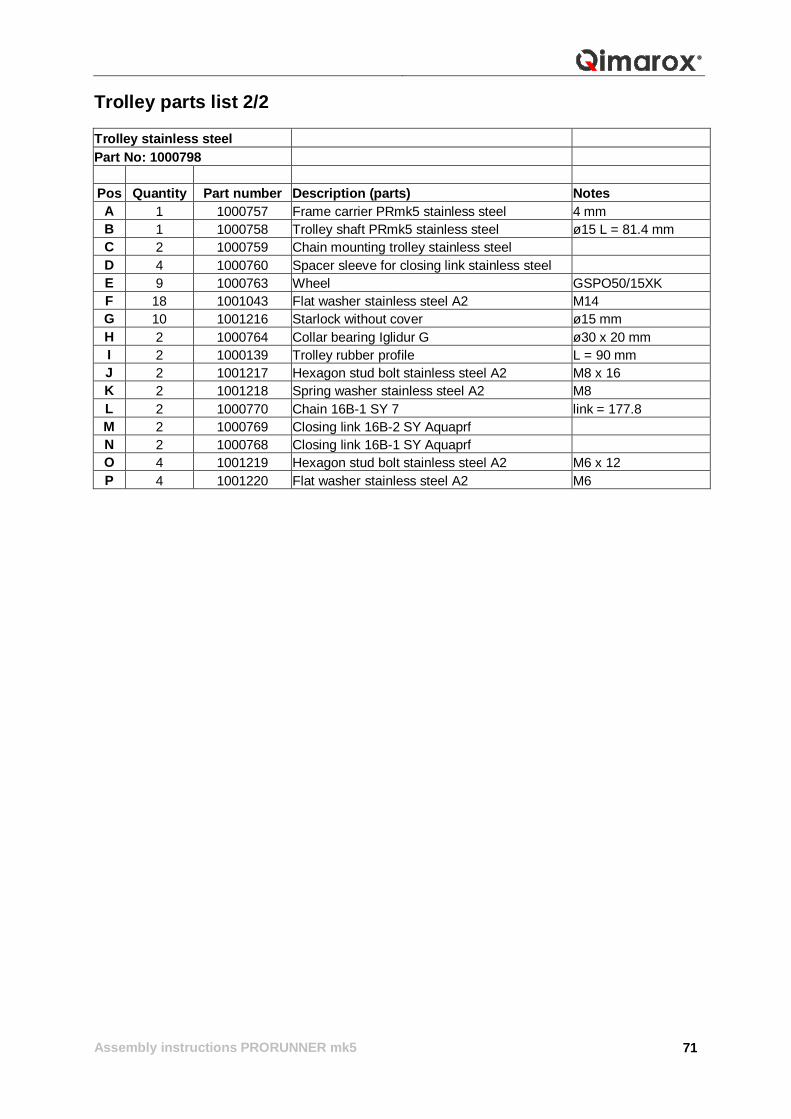
Trolley parts list 2/2 Trolley stainless steel Part No: 1000798
Pos Quantity Part number Description (parts) Notes A 1 1000757 Frame carrier PRmk5 stainless steel 4 mm B 1 1000758 Trolley shaft PRmk5 stainless steel ø15 L = 81.4 mm C 2 1000759 Chain mounting trolley stainless steel D 4 1000760 Spacer sleeve for closing link stainless steel E 9 1000763 Wheel GSPO50/15XK F 18 1001043 Flat washer stainless steel A2 M14 G 10 1001216 Starlock without cover ø15 mm H 2 1000764 Collar bearing Iglidur G ø30 x 20 mm I 2 1000139 Trolley rubber profile L = 90 mm J 2 1001217 Hexagon stud bolt stainless steel A2 M8 x 16 K 2 1001218 Spring washer stainless steel A2 M8 L 2 1000770 Chain 16B-1 SY 7 link = 177.8 M 2 1000769 Closing link 16B-2 SY Aquaprf N 2 1000768 Closing link 16B-1 SY Aquaprf O 4 1001219 Hexagon stud bolt stainless steel A2 M6 x 12 P 4 1001220 Flat washer stainless steel A2 M6
Assembly instructions PRORUNNER mk5
72
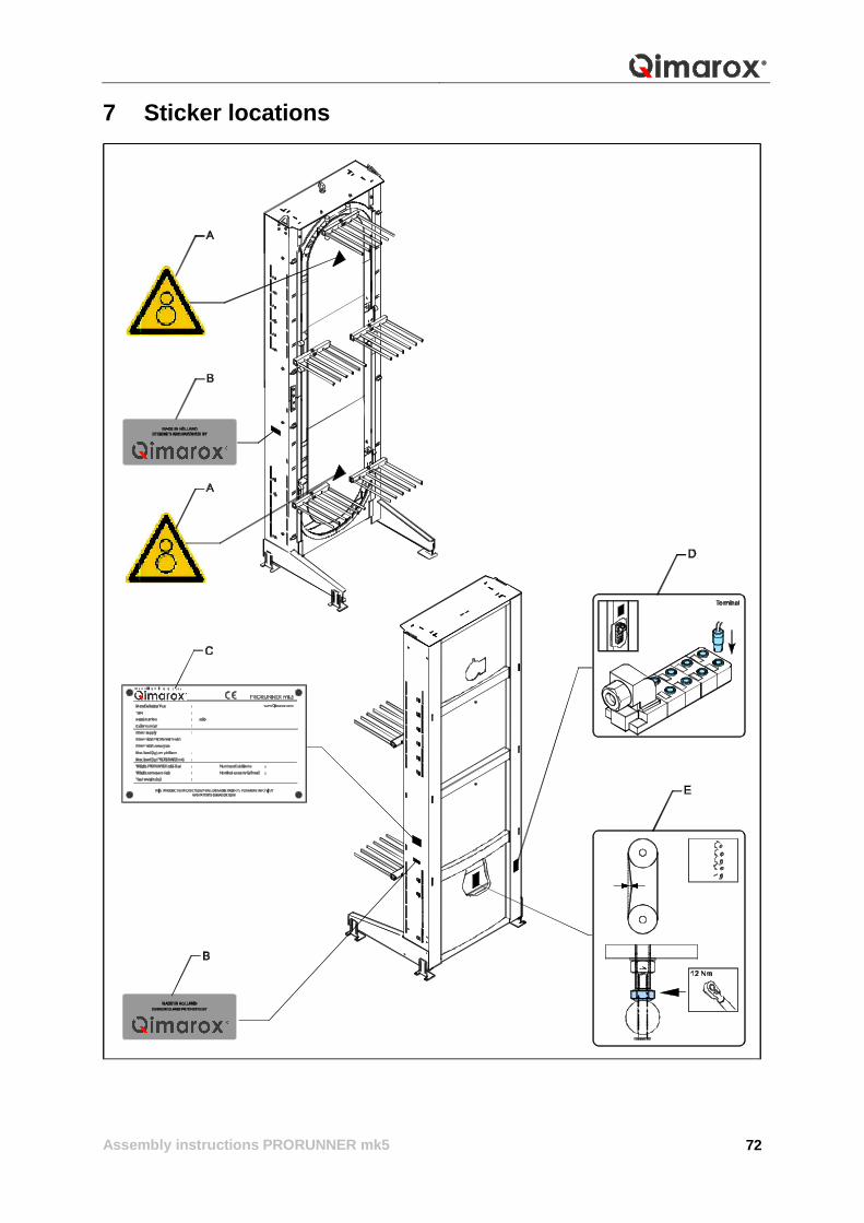
7 Sticker locations
Assembly instructions PRORUNNER mk5
73
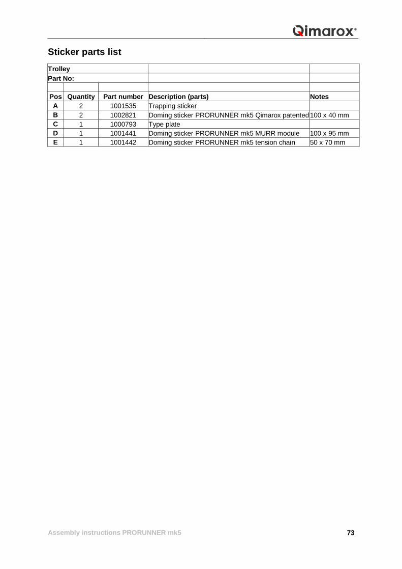
Sticker parts list Trolley Part No:
Pos Quantity Part number Description (parts) Notes A 2 1001535 Trapping sticker B 2 1002821 Doming sticker PRORUNNER mk5 Qimarox patented 100 x 40 mm C 1 1000793 Type plate D 1 1001441 Doming sticker PRORUNNER mk5 MURR module 100 x 95 mm E 1 1001442 Doming sticker PRORUNNER mk5 tension chain 50 x 70 mm
Assembly instructions PRORUNNER mk5
74
Nobelstraat 43 NL 3846 CE Harderwijk Tel: +31 341 436 700 Fax: +31 341 436 701 Email: [email protected] Internet: www.qimarox.com