assembly, inst allation, and removal of contacts and modules … coaxial user manual.pdf ·...
TRANSCRIPT

Assembly, InstAllAtIon, And RemovAl of ContACts And modulesFOR MINI COAXIAL CONTACTS AND MODULES
tAble of Contents
seCtIon 1 RECEIvER CONTACT ASSEMbLy INSTRUCTIONS
seCtIon 2 ITA CONTACT ASSEMbLy INSTRUCTIONS
seCtIon 3 WIRE WRAP CONTACT TERMINATION INSTRUCTIONS
seCtIon 4 CONTACT INSTALLATION AND REMOvAL INSTRUCTIONS
seCtIon 5 MODULE INSTALLATION AND REMOvAL INSTRUCTIONS
seCtIon 6 CROSS REFERENCE TAbLES
AppendIx PRODUCT PERFORMANCE SPECIFICATIONS
5/9/2017
Please note that any printed or downloaded User Manuals or Procedure Sheets may not reflect the most current revisions. The information contained in these materials is subject to change.
For the most current information available, visit www.vpc.com.

MINI COAXIAL CONTACTS AND MODULES USER’S MANUAL: SECTION 1 vIRgInIA pAnel CoRpoRAtIon
5/9/20171-1 For the most current information available, visit www.vpc.com.
mInI CoAxIAl ReCeIveR ContACt AssemblyPART # 610 104 114 FOR RG316
Assembly InstRuCtIons1. Strip wire (figure A).
2. Slide the crimp ring onto the wire (figure b).
3. Turn braid back over outer insulation (figure C).
*4. Solder center conductor wire into center conductor contact and clean (figure d). vPC solders per IPC’S J-STD-001. NOTE: Center conductor contact and dielectric must touch.
5. Slide shield conductor over center conductor until the center conductor stops in the Teflon® shield (figure e). NOTE: Shield conductor and Teflon insulator are supplied as an assembly.
Continued on next page...
tools ReQuIRed*Center Conductor Enlarging Tool, Part # 910 121 143*Center Conductor Forming Tool, Part # 910 121 119Hex Crimp Tool, Part # 910 101 115Inspection Depth Gauge, Part # 910 121 156Calibration Plug, Part # 414 854 104 (Included in Part # 910 121 156)
*Weight Gauge Kit, Part # 910 121 1314.0 oz. Weight, Part # 432 026 000 (included in Part # 910 121 131)0.5 oz. Weight, Part # 432 025 000 (included in Part # 910 121 131)
.174.32.40
10.16.70
17.78
CENTER CONDUCTOR WIRE
DIELECTRIC
SHIELD BRAIDOUTER INSULATION
Figure A. Strip wire.
CRIMP RING
Figure B. Crimp ring.
TURN SHIELD BRAID BACK
Figure C. Turn braid back.
NO GAP PERMISSIBLE
SOLDER
CENTER CONDUCTOR
Figure D. Solder center conductor.
SHIELD CONDUCTORASSEMBLY
SMALL GAP TO ENSURETHAT COAX CABLE HASBEEN FULLY INSERTED
Figure E. Slide shield conductor over center conductor.
Dimensions shown: [millimeters] inches
*When soldering, care must be taken so as to not deform the center conductor tip. If soldered properly, steps 8 and 9 can be skipped.
MINI COAXIAL CONTACTS AND MODULES USER’S MANUAL: SECTION 1 vIRgInIA pAnel CoRpoRAtIon
1-2 For the most current information available, visit www.vpc.com. 5/9/2017
mInI CoAxIAl ReCeIveR ContACt AssemblyPART # 610 104 114 FOR RG316
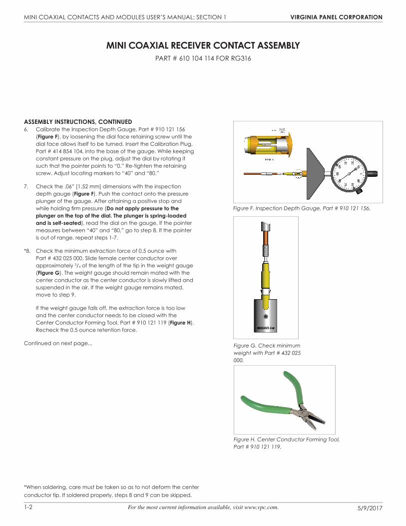
Assembly InstRuCtIons, ContInued6. Calibrate the Inspection Depth Gauge, Part # 910 121 156
(figure f), by loosening the dial face retaining screw until the dial face allows itself to be turned. Insert the Calibration Plug, Part # 414 854 104, into the base of the gauge. While keeping constant pressure on the plug, adjust the dial by rotating it such that the pointer points to “0.” Re-tighten the retaining screw. Adjust locating markers to “40” and “80.”
7. Check the .06” [1.52 mm] dimensions with the inspection depth gauge (figure f). Push the contact onto the pressure plunger of the gauge. After attaining a positive stop and while holding firm pressure (do not apply pressure to the plunger on the top of the dial. the plunger is spring-loaded and is self-seated), read the dial on the gauge. If the pointer measures between “40” and “80,” go to step 8. If the pointer is out of range, repeat steps 1-7.
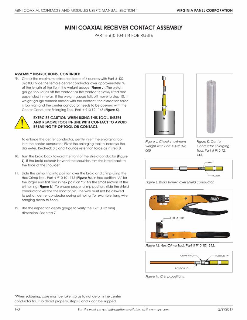
*8. Check the minimum extraction force of 0.5 ounce with Part # 432 025 000. Slide female center conductor over approximately 3/4 of the length of the tip in the weight gauge (figure g). The weight gauge should remain mated with the center conductor as the center conductor is slowly lifted and suspended in the air. If the weight gauge remains mated, move to step 9.
If the weight gauge falls off, the extraction force is too low and the center conductor needs to be closed with the Center Conductor Forming Tool, Part # 910 121 119 (figure H). Recheck the 0.5 ounce retention force.
Continued on next page...
Figure F. Inspection Depth Gauge, Part # 910 121 156.
Figure G. Check minimum weight with Part # 432 025 000.
Figure H. Center Conductor Forming Tool, Part # 910 121 119.
*When soldering, care must be taken so as to not deform the center conductor tip. If soldered properly, steps 8 and 9 can be skipped.
MINI COAXIAL CONTACTS AND MODULES USER’S MANUAL: SECTION 1 vIRgInIA pAnel CoRpoRAtIon
5/9/20171-3 For the most current information available, visit www.vpc.com.
mInI CoAxIAl ReCeIveR ContACt AssemblyPART # 610 104 114 FOR RG316
Assembly InstRuCtIons, ContInued*9. Check the maximum extraction force of 4 ounces with Part # 432
026 000. Slide the female center conductor over approximately 3/4 of the length of the tip in the weight gauge (figure J). The weight gauge should fall off the contact as the contact is slowly lifted and suspended in the air. If the weight gauge falls off move to step 10. If weight gauge remains mated with the contact, the extraction force is too high and the center conductor needs to be opened with the Center Conductor Enlarging Tool, Part # 910 121 143 (figure K).
exeRCIse CAutIon wHen usIng tHIs tool. InseRt And Remove tool In-lIne wItH ContACt to AvoId bReAKIng tIp of tool oR ContACt.
To enlarge the center conductor, gently insert the enlarging tool into the center conductor. Pivot the enlarging tool to increase the diameter. Recheck 0.5 and 4 ounce retention force as in step 8.
10. Turn the braid back toward the front of the shield conductor (figure l). If the braid extends beyond the shoulder, trim the braid back to the face of the shoulder.
11. Slide the crimp ring into position over the braid and crimp using the Hex Crimp Tool, Part # 910 101 115 (figure m), in hex position “A” for the larger end fi rst and in hex position “B” for the small section of the crimp ring (figure n). To ensure proper crimp position, slide the shield conductor over the the locator pin. The wire must not be allowed to pull on center conductor during crimping (for example, long wire hanging down to fl oor).
12. Use the inspection depth gauge to verify the .06” [1.52 mm] dimension. See step 7.
Figure J. Check maximum weight with Part # 432 026 000.
Figure K. Center Conductor Enlarging Tool, Part # 910 121 143.
SHOULDER
BRAID
Figure L. Braid turned over shield conductor.
Figure N. Crimp positions.
Figure M. Hex Crimp Tool, Part # 910 101 115.
CRIMP RING POSITION “A”
POSITION “C”
*When soldering, care must be taken so as to not deform the center conductor tip. If soldered properly, steps 8 and 9 can be skipped.
Figure M. Hex Crimp Tool, Part # 910 101 115.
LOCATOR

MINI COAXIAL CONTACTS AND MODULES USER’S MANUAL: SECTION 1 vIRgInIA pAnel CoRpoRAtIon
1-4 For the most current information available, visit www.vpc.com. 5/9/2017
Assembly InstRuCtIons1. Strip wire (figure A).
2. Slide the crimp ring onto the wire (figure b).
3. Turn braid back over outer insulation (figure C).
4. Slide the spacer tube over the dielectric to edge of the braid (figure d). Use heat gun to shrink spacer to hold onto dielectric.
5. Tin wire and solder into center conductor and clean (figure e). vPC solders per IPC’S J-STD-001.NOTE: Center conductor and dielectric must touch. Solder should be visible in the hole.
6. Slide shield conductor over center conductor until the center conductor stops in the Tefl on® shield. To ensure that the coaxial cable has been fully inserted into the contact, a gap between the shielding and the contact should exist after achieving positive stop (figure f).NOTE: Shield conductor and Tefl on insulator are supplied as an assembly.
Continued on next page...
tools ReQuIRedCenter Conductor Enlarging Tool, Part # 910 121 143Center Conductor Forming Tool, Part # 910 121 119Hex Crimp Tool, Part # 910 101 115Inspection Depth Gauge, Part # 910 121 156Calibration Plug, Part # 414 854 104 (Included in Part # 910 121 156)
Weight Gauge Kit, Part # 910 121 1314.0 oz. Weight, Part # 432 026 000 (included in Part # 910 121 131)0.5 oz. Weight, Part # 432 025 000 (included in Part # 910 121 131)
mInI CoAxIAl ReCeIveR ContACt AssemblyPART # 610 104 141 FOR RG178
0.17[4.32]
0.39[9.90]
0.65[16.51]
OUTER INSULATIONBRAID DIELECTRIC CONDUCTOR
WIRE
Figure A. Strip wire.
Figure B. Crimp ring.
Figure D. Spacer tube.
Figure E. Ensure solder is visible in hole.
Figure F. Shield conductor.
Dimensions shown: [millimeters] inches
Figure C. Turn braid back.

MINI COAXIAL CONTACTS AND MODULES USER’S MANUAL: SECTION 1 vIRgInIA pAnel CoRpoRAtIon
5/9/20171-5 For the most current information available, visit www.vpc.com.
Assembly InstRuCtIons, ContInued7. Calibrate the Inspection Depth Gauge, Part # 910 121 156 (figure
g) by loosening the dial face retaining screw until the dial face allows itself to be turned. Insert the Calibration Plug, Part # 414 854 104 into base of gauge. While keeping constant pressure on the plug, adjust the dial by rotating it such that the pointer points to “0.” Re-tighten retaining screw. Adjust locating markers to “40” and “80.”
8. Check the .06” [1.52 mm] dimensions with the inspection depth gauge (figure g). Push the contact onto the pressure plunger of the gauge. After attaining a positive stop and while holding fi rm pressure (do not apply pressure to the plunger on the top of the dial. the plunger is spring-loaded and is self-seated), read the dial on the gauge. If the pointer measures between “40” and “80,” go to step 9. If the pointer is out of range, repeat steps 1-8.
9. Check the minimum extraction force of 0.5 ounce with Part # 432 025 000. Slide the female center conductor over approximately 3/4 of the length of the tip in the weight gauge (figure H). The weight gauge should remain mated with the center conductor as the center conductor is slowly lifted and suspended in the air. If weight gauge remains mated, move to step 10.
If the weight gauge falls off, the extraction force is too low and the center conductor needs to be closed with the Center Conductor Forming Tool, Part # 910 121 119 (figure J). Recheck the 0.5 ounce retention force.
Continued on next page...
mInI CoAxIAl ReCeIveR ContACt AssemblyPART # 610 104 141 FOR RG178
Figure G. Inspection Depth Gauge, Part # 910 121 156.
Figure H. Check minimum extraction force with Part # 432 025 000.
Figure J. Center Conductor Forming Tool, Part # 910 121 119.

MINI COAXIAL CONTACTS AND MODULES USER’S MANUAL: SECTION 1 vIRgInIA pAnel CoRpoRAtIon
1-6 For the most current information available, visit www.vpc.com. 5/9/2017
Assembly InstRuCtIons, ContInued10. Check the maximum extraction force of 4 ounces with Part # 432
026 000. Slide the female center conductor over approximately 3/4 of the length of the tip in the weight gauge (figure K). The weight gauge should fall off the contact as the contact is slowly lifted and suspended in the air. If the weight gauge falls off move to step 11. If the weight gauge remains mated with contact, the extraction force is too high and the center conductor needs to be opened with the Center Conductor Enlarging Tool, Part # 910 121 143 (figure l).
exeRCIse CAutIon wHen usIng tHIs tool. InseRt And Remove tool In-lIne wItH ContACt to AvoId bReAKIng tIp of tool oR ContACt.
To enlarge the center conductor, gently insert the enlarging tool into the center conductor. Pivot the enlarging tool to increase the diameter. Recheck 0.5 and 4 ounce retention force as in step 9.
11. Turn the braid back toward the front of the shield conductor (figure m). If the braid extends beyond shoulder, trim braid back to face of shoulder.
12. Slide the crimp ring into position over the braid and crimp using the Hex Crimp Tool, Part # 910 101 115 (figure n) in hex position “A” for the larger end fi rst and in hex position “C” for the smaller section of the crimp ring (figure o). To ensure proper crimp position, slide the shield conductor over pin on locator attached to hex crimp tool. Wire must not be allowed to pull on center conductor during crimping (for example, long wire hanging down to fl oor).
15. Use the inspection depth gauge to verify the .06” [1.52 mm] dimension. See step 8.
mInI CoAxIAl ReCeIveR ContACt AssemblyPART # 610 104 141 FOR RG178
Figure K. Check maximum extraction force with Part # 432 026 000.
Figure L. Center Conductor Enlarging Tool, Part # 910 121 143.
SHOULDER
BRAID
Figure M. Turn braid back over shield conductor.
Figure O. Crimp positions.
POSITION "A"
POSITION"C"
CRIMP RING
Figure N. Hex Crimp Tool, Part # 910 101 115.
LOCATOR

MINI COAXIAL CONTACTS AND MODULES USER’S MANUAL: SECTION 1 vIRgInIA pAnel CoRpoRAtIon
5/9/20171-7 For the most current information available, visit www.vpc.com.
Assembly InstRuCtIons1. Strip wire (figure A).
2. Slide the crimp ring onto the wire (figure b).
3. Turn both the inner and outer braid back over the outer insulation. Turn the outer braid back and smooth then turn the inner braid back (figure b).
4. Insert the center conductor of the wire into the center conductor contact, solder and clean (figure C). vPC solders per IPC’S J-STD-001. NOTE: Center conductor contact and dielectric must touch.
5. Slide the shield conductor over the center conductor until the center conductor stops in the Teflon® insulator (figure d). NOTE: Shield conductor and Teflon insulator are supplied as an assembly.
6. Check to ensure that the center conductor is flush with the Teflon insulator (figure e).
7. Calibrate the Inspection Depth Gauge, Part # 910 121 156 (figure f), by loosening the dial face retaining screw until the dial face can be turned. Insert the Calibration Plug, Part # 414 855 104 into the base of the gauge. While keeping constant pressure on the plug, adjust the dial by rotating it so that the pointer points to “0.” Re-tighten the retaining screw. Adjust the locating markers to “40” and “80.”
8. Check the .06” [1.52 mm] dimension with the inspection depth gauge (figure f). Push the contact onto the pressure plunger of the gauge. After attaining a positive stop and while holding firm pressure, push the plunger on top of the dial (to push collar over Teflon), read the dial on the gauge. If the pointer measures between “40” and “80,” go to step 9. If the pointer is out of the range, repeat steps 1-8.
Continued on next page...
tools ReQuIRedCenter Conductor Enlarging Tool, Part # 910 121 143Center Conductor Forming Tool, Part # 910 121 119Hex Crimp Tool, Part # 910 101 115Inspection Depth Gauge, Part # 910 121 156Calibration Plug, Part # 414 855 104 (Included in Part # 910 121 156)
Weight Gauge Kit, Part # 910 121 1310.5 oz. weight, Part # 432 025 000 (included in Part # 910 121 131)4 oz. weight, Part # 432 026 000 (included in Part # 910 121 131)
mInI CoAxIAl ReCeIveR ContACt AssemblyPART # 610 104 149 FOR RG316 DOUbLE SHIELDED
.17
.379.4.66
16.76
[4.31]
BRAIDDIELECTRIC
CONDUCTORWIRE
Figure A. Strip wire.
Figure B. Crimp ring.
FOLD BRAID BACKCRIMP RING
Figure C. Assemble wire into contact.
NO GAP PERMISSIBLE
CENTER CONDUCTOR CONTACTSOLDER
Figure D. Slide shield conductor over center conductor.SHIELD CONDUCTOR
.06±.021.52±0.51
CENTER CONDUCTOR CONTACT
TEFLON INSULATOR
Figure E. Ensure center conductor is flush with Teflon insulator.
Figure F. Inspection Depth Gauge, Part # 910 121 156.
A
INSPECTION DEPTH GAUGE
.06[1.52]
0
DETAIL A
Dimensions shown: [millimeters] inches

MINI COAXIAL CONTACTS AND MODULES USER’S MANUAL: SECTION 1 vIRgInIA pAnel CoRpoRAtIon
1-8 For the most current information available, visit www.vpc.com. 5/9/2017
Assembly InstRuCtIons, ContInued9. Check minimum extraction force of 0.5 ounce with Part # 432
025 000. Slide female center conductor over approximately 3/4 the length of the tip in the weight gauge (figure g). The weight gauge should remain mated with the center conductor as the center conductor is slowly lifted and suspended in the air. If weight gauge remains mated, move to step 10.
If weight gauge falls off, the extraction force is too low and the center conductor needs to be closed with the Center Conductor Forming Tool, Part # 910 121 119 (figure H). Recheck the 0.5 ounce retention force.
10. Check maximum extraction force of 4 ounces with Part # 432 026 000. Slide female center conductor over approximately 3/4 of the length of the tip in the weight gauge (figure J). The weight gauge should fall off the contact as the contact is slowly lifted and suspended in the air. If weight gauge falls off move to step 10. If weight gauge remains mated with the contact, the extraction force is too high and the center conductor needs to be opened with the Center Conductor Enlarging Tool, Part # 910 121 143 (figure K).
exeRCIse CAutIon wHen usIng tHIs tool. InseRt And Remove tool In-lIne wItH ContACt to AvoId bReAKIng tIp of tool oR ContACt.
To enlarge the center conductor, gently insert the enlarging tool into the center conductor. Pivot the enlarging tool to increase the diameter. Recheck 0.5 and 4 ounce retention force as in step 9.
11. Turn both braids back over the shield conductor (figure l). If the braid extends beyond the shoulder, trim the braid back to the face of the shoulder.
12. Slide the crimp ring over the braid and shield conductor (figure m) and crimp using the Hex Crimp Tool, Part # 910 101 115, in hex position “A”. To ensure proper crimp position, slide the shield conductor over the dowel pin on the hex crimp tool. The wire must not be allowed to pull on the center conductor during crimping (For example, long wire hanging down to floor).
13. Use the inspection depth gauge to verify the .06” [1.52 mm] dimension. See step 8.
Figure M. Slide the crimp ring over the braid and crimp.
SHOULDER
BRAID
Figure G. Check minimum extraction force with Part # 432 025 000.
CRIMP POSITION "A"CRIMP RING
Figure L. Turn braids back over shield conductor.
Figure J. Check maximum extraction force with Part # 432 026 000.
Figure K. Center Conductor Enlarging Tool, Part # 910 121 143.
Figure H. Center Conductor Forming Tool, Part # 910 121 119.
mInI CoAxIAl ReCeIveR ContACt AssemblyPART # 610 104 149 FOR RG316 DOUbLE SHIELDED
MINI COAXIAL CONTACTS AND MODULES USER’S MANUAL: SECTION 1 vIRgInIA pAnel CoRpoRAtIon
5/9/20171-9 For the most current information available, visit www.vpc.com.
mInI CoAxIAl ReCeIveR ContACt AssemblyPART # 610 104 154 FOR RG58
tools ReQuIRedHex Crimp Tool, Part # 910 101 115Inspection Depth Gauge, Part # 910 121 156
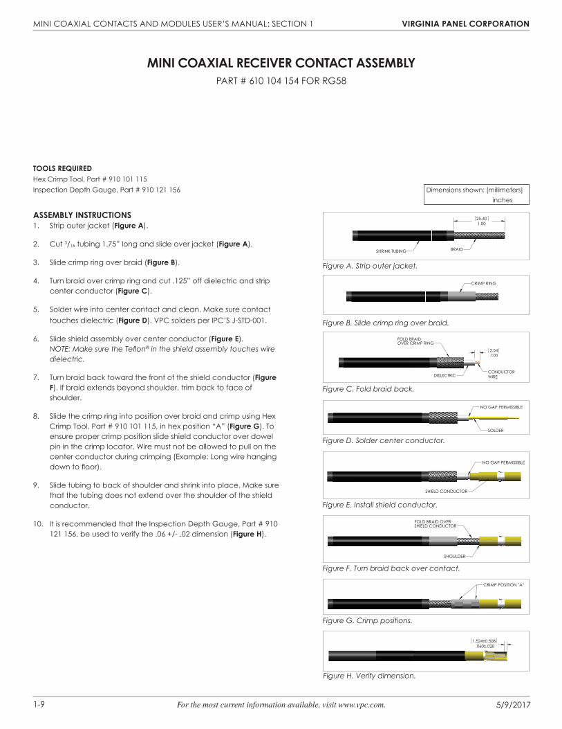
Assembly InstRuCtIons1. Strip outer jacket (figure A).
2. Cut 3/16 tubing 1.75” long and slide over jacket (figure A).
3. Slide crimp ring over braid (figure b).
4. Turn braid over crimp ring and cut .125” off dielectric and strip center conductor (figure C).
5. Solder wire into center contact and clean. Make sure contact touches dielectric (figure d). vPC solders per IPC’S J-STD-001.
6. Slide shield assembly over center conductor (figure e). NOTE: Make sure the Teflon® in the shield assembly touches wire dielectric.
7. Turn braid back toward the front of the shield conductor (figure f). If braid extends beyond shoulder, trim back to face of shoulder.
8. Slide the crimp ring into position over braid and crimp using Hex Crimp Tool, Part # 910 101 115, in hex position “A” (figure g). To ensure proper crimp position slide shield conductor over dowel pin in the crimp locator. Wire must not be allowed to pull on the center conductor during crimping (Example: Long wire hanging down to floor).
9. Slide tubing to back of shoulder and shrink into place. Make sure that the tubing does not extend over the shoulder of the shield conductor.
10. It is recommended that the Inspection Depth Gauge, Part # 910 121 156, be used to verify the .06 +/- .02 dimension (figure H).
Figure A. Strip outer jacket.
Figure B. Slide crimp ring over braid.
Figure C. Fold braid back.
Figure D. Solder center conductor.
Figure E. Install shield conductor.
Figure F. Turn braid back over contact.
Figure G. Crimp positions.
Figure H. Verify dimension.
Dimensions shown: [millimeters] inches
1.0025.40
SHRINK TUBING BRAID
CRIMP RING
.1002.54
FOLD BRAIDOVER CRIMP RING
CONDUCTORWIREDIELECTRIC
SOLDER
NO GAP PERMISSIBLE
SHIELD CONDUCTOR
NO GAP PERMISSIBLE
FOLD BRAID OVERSHIELD CONDUCTOR
SHOULDER
CRIMP POSITION "A"
.060±.0201.524±0.508

MINI COAXIAL CONTACTS AND MODULES USER’S MANUAL: SECTION 1 vIRgInIA pAnel CoRpoRAtIon
1-10 For the most current information available, visit www.vpc.com. 5/9/2017
tools ReQuIRedSolder Kit, includes Holding Fixture and Adapter, Part # 910 121 144Adapter (for those who already own a holding fi xture), Part # 910 121 149Steinel Heat Gun with nozzle, Part # 910 121 160 - 110v or Part # 910 121 167 - 220v
Assembly InstRuCtIons1. Strip wire (figure A).
2. Straighten the center conductor making sure the stranded center conductor is twisted into its original lay.
3. Tin stranded center conductor with Sn63 solder per QQ-S-571. Use RMA fl ux per MIL-F-14256 (Alpha #611 or equivalent).
4. Make sure the shield braid is trimmed evenly and no loose strands are extending out across the exposed dielectric or cable jacket.
5. Smooth the braid ends fl at against the cable dielectric.
6. Slide the contact over the end of the prepared cable, and carefully push the contact onto the cable until it stops. Rotating the contact slightly during cable insertion will help prevent the braid from catching.
7. Inspect for proper insertion (figure b). The center conductor must be visible through one of the forward inspection windows. The distance from the rear of the contact outer body to the cable jacket insulation should be 0.065” [1.65 mm].
8. Install the Adapter, Part # 910 121 149, onto the Holding Fixture, Part # 910 121 144 (figure C). Insert contact in the adapter side marked “S” for socket, and set up the dimensions (figure C).
9. Insert the contact/cable assembly into the adapter. Clamp the cable in the holding fi xture. The cable must remain fully inserted in the contact and the contact must be fully inserted in the adapter for the adapter to act as a heat sink. The cable must be straight between the contact and the cable clamp.
10. Attach the appropriate refl ector to the heating tool. See instruction sheet accompanying heat gun for instructions and safety precautions.
11. Using the holding fi xture, position the contact in the heating tool refl ector with the forward inspection window centered in the refl ector. Continue heating until the small solder preform in the forward inspection window has melted and fl owed. The large solder preform in the rear inspection window should have melted and fl owed by this time; if it has not, direct hot air at the rear inspection window until it does.
12. If contact is UNDERHEATED, there will be visible remnants of the original shapes of the solder preforms. An underheated contact must be re-heated. If contact is OVERHEATED, solder will wick away from the joint areas, leaving no solder fi llets. An overheated contact must be removed and a new contact installed.
13. After the contact has cooled for at least 10 seconds, remove the contact and cable from the holding fi xture.
14. Inspect the completed termination for correct assembly. The cable shield must extend into the contact at least as far as the front edge of the rear inspection windows. The center conductor must be visible through one of the forward inspection windows.
mInI CoAxIAl ReCeIveR, soldeR sleeve®, ContACt AssemblyPART # 610 104 142 FOR RG316
.115±.0152.92±0.38.190±.0154.83±0.38
.360±.0159.14±0.38
CONDUCTORWIREDIELECTRIC
BRAID
.0651.65
CENTER CONDUCTOR WIRE
FORWARD INSPECTION WINDOW
REAR INSPECTION WINDOW
.061.52
SIDE MARKED "S"
FORWARD INSPECTIONWINDOW
ADAPTER
CONTACT
HOLDING FIXTURE
Figure A. Strip wire.
Figure B. Contact on wire.
Figure C. Holding fi xture.
Dimensions shown: [millimeters] inches

1-11 For the most current information available, visit www.vpc.com.
MINI COAXIAL CONTACTS AND MODULES USER’S MANUAL: SECTION 1 vIRgInIA pAnel CoRpoRAtIon
5/9/2017
tools ReQuIRedSolder Kit, includes Holding Fixture and Adapter, Part # 910 121 144Adapter (for those who already own a holding fi xture), Part # 910 121 149Steinel Heat Gun with nozzle, Part # 910 121 160 - 110v or Part # 910 121 167 - 220v
Assembly InstRuCtIons1. Strip wire for braid and dielectric (figure A).
2. Turn braid back, smoothing ends fl at against cable jacket.
3. Strip for center conductor (figure b).
2. Straighten the center conductor making sure the stranded center conductor is twisted into its original lay.
3. Tin stranded center conductor with Sn63 solder per QQ-S-571. Use RMA fl ux per MIL-F-14256 (Alpha #611 or equivalent).
4. Fold the center conductor back on itself (figure C).
5. Make sure the shield braid is trimmed evenly and no loose strands are extending out across the exposed dielectric or cable jacket.
6. Smooth the braid ends fl at against the cable jacket.
7. Slip the contact over the end of the prepared cable, and carefully push the contact onto the cable until it stops. Rotating the contact slightly during cable insertion will help prevent the braid from catching.
8. Inspect for proper insertion (figure d). The center conductor must be visible through one of the forward inspection windows. The distance from the rear of the contact outer body to the edge of the braid should be 0.015” [0.38 mm].
9. Install the Adapter, Part # 910 121 149, onto the Holding Fixture, Part # 910 121 144 (figure e). Insert a contact in the adapter side marked “S” for socket, and set up the dimensions (figure e).
10. Insert the contact/cable assembly into the adapter. Clamp the cable in the holding fi xture. The cable must remain fully inserted in the contact and the contact must be fully inserted in the adapter for adapter to act as a heat sink. The cable must be straight between the contact and the cable clamp.
11. Attach the appropriate refl ector to the heating tool. See instruction sheet accompanying heat gun for instructions and safety precautions.
12. Using the holding fi xture, position the contact in the heating tool refl ector with the forward inspection window centered in the refl ector. Continue heating until the small solder preform in the forward inspection window has melted and fl owed. The large solder preform in the rear inspection window should have melted and fl owed by this time; if it has not, direct hot air at the rear inspection window until it does.
13. If contact is UNDERHEATED, there will be visible remnants of the original shapes of the solder preforms. An underheated contact must be re-heated. If contact is OVERHEATED, solder will wick away from the joint areas, leaving no solder fi llets. An overheated contact must be removed and a new contact installed.
14. After the contact has cooled for at least 10 seconds, remove the contact and cable from the holding fi xture.
15. Inspect the completed termination for correct assembly. The cable shield must extend into the contact at least as far as the front edge of the rear inspection windows. The center conductor should be visible through one of the forward inspection windows.
mInI CoAxIAl ReCeIveR, soldeR sleeve® , ContACt AssemblyPART # 610 104 142 FOR RG178 AND JOy CAbLE (TyPE 033, 93 OHMS)
Figure A. Strip wire.
Figure C. Fold center conductor.
Figure B. Strip center conductor.
Figure D. Contact on wire.
Figure E. Holding fi xture.
7.37.290
.1403.56
DIELECTRICBRAID
.115[2.92]
CONDUCTOR WIRE
.215[5.46]
CONDUCTOR WIRE
.0651.65
CENTER CONDUCTOR WIRE
FORWARD INSPECTION WINDOW
REAR INSPECTION WINDOW
.061.52
SIDE MARKED "S"
FORWARD INSPECTIONWINDOW
ADAPTER
CONTACT
HOLDING FIXTURE
Dimensions shown: [millimeters] inches

MINI COAXIAL CONTACTS AND MODULES USER’S MANUAL: SECTION 2 vIRgInIA pAnel CoRpoRAtIon
5/9/20172-1 For the most current information available, visit www.vpc.com.
mInI CoAxIAl ItA ContACt AssemblyPART # 610 103 115 FOR RG316
tools ReQuIRedOuter Shield Conductor Expanding Tool, Part # 910 121 142Outer Shield Conductor Forming Tool, Part # 910 121 126Hex Crimp Tool, Part # 910 101 115Inspection Depth Gauge, Part # 910 121 157Calibration Plug, Part # 414 855 103 (included in Part # 910 121 157)
Weight Gauge Kit, Part # 910 121 1553 oz. weight, Part # 414 852 000 (included in kit Part # 910 121 155)20 oz. weight, Part # 414 853 000 (included in kit Part # 910 121 155)
.66[16.76]
.37[9.40]
.17[4.32]
BRAIDDIELECTRIC
CONDUCTORWIREOUTER
INSULATION
CRIMP RING
BRAID
NO GAP PERMISSIBLE SOLDER
CENTER CONDUCTOR
CENTER CONDUCTOR
SHIELD CONDUCTOR
SMALL GAP TO ENSURE THATCOAX CABLE HAS BEEN FULLYINSERTED INTO CONTACT
BRAID SHOULDER
Figure A. Strip wire.
Figure B. Crimp ring.
Figure D. Fold braid back.
Figure C. Solder center conductor wire.
Figure E. Slide shield conductor on.
Figure F. Fold braid over.
Assembly InstRuCtIons1. Strip wire (figure A).
2. Slide the crimp ring onto the wire (figure b).
3. Solder wire into center conductor and clean (figure C). vPC solders per IPC’S J-STD-001.NOTE: Center conductor and dielectric must touch.
4. Turn braid back over outer insulation (figure d).
5. Slide the shield over the center conductor tip until it stops. There shall be a gap between the Tefl on and the folded braid to ensure the center conductor is fully inserted into the contact(figure e). NOTE: Shield conductor and tefl on insulator are supplied as an assembly.
6. Turn the braid back toward the front of the shield conductor and wrap evenly (figure f). If braid extends beyond shoulder, trim back to face of shoulder.
Continued on next page...
Dimensions shown: [millimeters] inches

MINI COAXIAL CONTACTS AND MODULES USER’S MANUAL: SECTION 2 vIRgInIA pAnel CoRpoRAtIon
5/9/20172-2 For the most current information available, visit www.vpc.com.
mInI CoAxIAl ItA ContACt AssemblyPART # 610 103 115 FOR RG316
Assembly InstRuCtIons, ContInued7. Slide crimp ring into position over the braid (figure g). Do not
crimp.
8. Calibrate the Inspection Depth Gauge, Part # 910 121 157 (figure H) by loosening the dial face retaining screw until the dial face allows itself to be turned. Insert the Calibration Plug, Part # 414 855 103 into base of gauge. While keeping constant pressure on the plug, adjust the dial by rotating it such that the pointer points to “0.” Re-tighten retaining screw. Adjust locating markers to “20” and “90.”
9. Check the .01 [.25 mm] dimension (figure J) with the inspection depth gauge (figure H). Push the contact onto the pressure plunger of the gauge. After attaining a positive stop and while holding fi rm pressure (do not apply pressure to the plunger on the top of the dial. the plunger is spring-loaded and is self-seated), read the dial on the gauge. If the pointer measures between “20” and “90,” go to step 10. If the pointer is out of the range, repeat steps 1-9.
10. To ensure proper crimp position, slide shield conductor over the locator pin (figure K). Ensure insulator is fl ush with shield (figure l) prior to crimping. Crimp using the Hex Crimp Tool, Part # 910 101 115 (figure m) in hex position “A” for the larger end fi rst, and in hex position “b” for the smaller section of the crimp ring. Wire must not be allowed to pull on the center conductor during crimping (for example, long wire hanging down to fl oor). Verify that the insulator is fl ush with shield (figure n).
Continued on next page...
Figure G. Slide crimp ring over braid.
Figure J. Check dimensions.
.010[0.254]
Figure H. Inspection Depth Gauge, Part # 910 121 157.
A
DETAIL A
Figure M. Hex Crimp Tool, Part # 910 101 115.Figure M. Hex Crimp Tool, Part # 910 101 115.
LOCATOR
Figure L. Flush insulator to shield.
Figure N. Verify insulator is fl ush with shield.
Figure K. Slide shield conductor over pin on locator.
LOCATORPOSITION "A"
POSITION "b"

MINI COAXIAL CONTACTS AND MODULES USER’S MANUAL: SECTION 2 vIRgInIA pAnel CoRpoRAtIon
5/9/20172-3 For the most current information available, visit www.vpc.com.
mInI CoAxIAl ItA ContACt AssemblyPART # 610 103 115 FOR RG316
Assembly InstRuCtIons, ContInued11. Check the minimum extraction force of 3 ounces with
Part # 414 852 000. Slide contact the weight gauge tip. Insert approximately 0.15” [3.81 mm] into tip. Take care not to insert chamfer of contact the weight gauge tip (figure n). The weight gauge should remain mated with the contact as the contact is slowly lifted and suspended in the air. If weight gauge remains mated move to step 12. If weight gauge falls off, the extraction force is too low and the shield conductor needs to be opened up with the Outer Shield Conductor Expanding Tool, Part # 910 121 142 (figure o). To enlarge the shield conductor, gently insert the enlarging tool into the contact. be careful not to bend the contact center conductor. Once inserted into the contact, pivot the enlarging tool to increase the shield diameter. Repeat until 3 ounce weight gauge can be held by contact.
12. Check the maximum extraction force of 20 ounces with Part # 414 853 000. Slide contact the weight gauge tip. Insert approximately 0.15” [3.81 mm] into tip. Take care not to insert chamfer of contact the weight gauge tip (figure p). The weight gauge should fall off the contact as the contact is slowly lifted and suspended in the air. If the weight gauge falls off move to step 13. If weight gauge remains mated with contact, the extraction force is too high and the shield conductor needs to be closed with the Outer Shield Conductor Forming Tool, Part # 910 121 126 (figure Q). Squeezing the tool handles will reposition the contact legs. This procedure should be done in three different locations (approximately 120° apart) on the same shield to obtain proper sizing. Repeat steps 11 and 12. Do not pass slotted end of contact.
13. Use the inspection depth gauge to verify the .01" [.25 mm] dimension. See step 9.
14. Verify insulator is flush to .015" max protrusion with shield. See step 10.
Figure N. Check minimum extraction force with Part # 414 852 000.
Figure P. Check maximum extraction force with Part # 414 853 000.
Figure O. Outer Shield Conductor Expanding Tool, Part # 910 121 142.
Figure Q. Outer Shield Conductor Forming Tool, Part # 910 121 126.

MINI COAXIAL CONTACTS AND MODULES USER’S MANUAL: SECTION 2 vIRgInIA pAnel CoRpoRAtIon
5/9/20172-4 For the most current information available, visit www.vpc.com.
mInI CoAxIAl ItA ContACt AssemblyPART # 610 103 130 FOR RG178, PART # 610 103 157 FOR RG178
Assembly InstRuCtIons1. Strip wire (figure A).
2. Slide the crimp ring onto the wire (figure b).
3. Turn braid back over outer insulation (figure C).
4. Slide the spacer tube over dielectric to edge of the braid (figure d). Heat spacer tube until spacer shrinks to hold onto dielectric.
5. Slide the center conductor wire into the center conductor contact and solder. Clean solder joint (figure d). vPC solders per IPC’S J-STD-001.NOTE: Center conductor and dielectric must touch.
6. Slide the shield over the center conductor tip until it stops. There shall be a gap between the Tefl on and the folded braid to ensure the center conductor is fully inserted into the contact (figure e). NOTE: Shield conductor and tefl on insulator are supplied as an assembly.
7. Turn braid back over the shield conductor and wrap evenly (figure f). If braid extends beyond shoulder, trim back to face of shoulder.
Continued on next page...
tools ReQuIRedOuter Shield Conductor Expanding Tool, Part # 910 121 142Outer Shield Conductor Forming Tool, Part # 910 121 126Hex Crimp Tool, Part # 910 101 115Inspection Depth Gauge, Part # 910 121 157Calibration Plug, Part # 414 855 103 (included in Part # 910 121 157)
Weight Gauge Kit, Part # 910 121 1553 oz. weight, Part # 414 852 000 (included in kit Part # 910 121 155)20 oz. weight, Part # 414 853 000 (included in kit Part # 910 121 155)
Figure A. Strip wire.
Figure B. Crimp ring.
Figure C. Turn braid back.
Figure D. Install center conductor contact.
Figure E. Install shield conductor.
Figure F. Turn braid over contact.
4.32.17
9.14.36
.6817.27
BRAIDDIELECTRIC
CONDUCTORWIREINSULATION
OUTER
Dimensions shown: [millimeters] inches
FOLD bRAID OvER SHIELD CONDUCTOR
SHOULDER
SHOULDERSMALL GAP
SPACER TUbE
CENTER CONDUCTOR CONTACT
SOLDERNO GAP PERMISSIbLE
FOLD bRAID bACKCRIMP RING
CRIMP RING

MINI COAXIAL CONTACTS AND MODULES USER’S MANUAL: SECTION 2 vIRgInIA pAnel CoRpoRAtIon
5/9/20172-5 For the most current information available, visit www.vpc.com.
mInI CoAxIAl ItA ContACt AssemblyPART # 610 103 130 FOR RG178, PART # 610 103 157 FOR RG178
Assembly InstRuCtIons, ContInued8. Slide crimp ring into position over the braid (figure g). Do not
crimp.
9. Calibrate the Inspection Depth Gauge, Part # 910 121 157 (figure H), by loosening the dial face retaining screw until the dial face allows itself to be turned. Insert the Calibration Plug, Part # 414 855 103, into base of gauge. While keeping constant pressure on the plug, adjust the dial by rotating it such that the pointer points to “0.” Re-tighten retaining screw. Adjust locating markers to “20” and “90.”
10. Check the .01” [.25 mm] dimension (figure J) by using Part # 910 121 157 (figure H). Insert contact into the gauge and push contact into collar until contact stops. After attaining a positive stop and while holding fi rm pressure (do not apply pressure to the plunger on the top of the dial. the plunger is spring-loaded and is self-seated), read the dial on the gauge. If pointer is between the two markers, go to step 11. If the pointer is out of the range of the two markers, repeat steps 1-10.
11. To ensure proper crimp position, slide the shield conductor over the locator pin (figure K). Ensure insulator is fl ush with shield (figure l) prior to crimping. Crimp using the Hex Crimp Tool, Part # 910 101 115 (figure m) in hex position “A” for the larger end fi rst, and in hex position “C” for the smaller section of the crimp ring. Wire must not be allowed to pull on the center conductor during crimping (for example, long wire hanging down to fl oor). Verify that the insulator is fl ush with shield (figure n).
Continued on next page...
Figure G. Slide crimp ring over braid.
Figure J. Check dimensions.
.010[0.254]
Figure H. Inspection Depth Gauge, Part # 910 121 157.
A
DETAIL A
Figure M. Hex Crimp Tool, Part # 910 101 115.Figure M. Hex Crimp Tool, Part # 910 101 115.
LOCATOR
Figure L. Flush insulator to shield.
Figure N. Verify insulator is fl ush with shield.
Figure K. Slide shield conductor over pin on locator.
LOCATORPOSITION "A"
POSITION "b"
MINI COAXIAL CONTACTS AND MODULES USER’S MANUAL: SECTION 2 vIRgInIA pAnel CoRpoRAtIon
5/9/20172-6 For the most current information available, visit www.vpc.com.
mInI CoAxIAl ItA ContACt AssemblyPART # 610 103 130 FOR RG 178 / 610 103 157 FOR RG 178
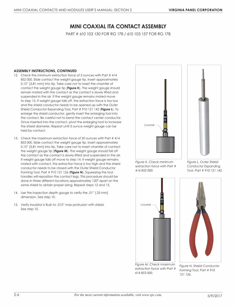
Assembly InstRuCtIons, ContInued12. Check the minimum extraction force of 3 ounces with Part # 414
852 000. Slide contact the weight gauge tip. Insert approximately 0.15” [3.81 mm] into tip. Take care not to insert the chamfer of contact the weight gauge tip (figure K). The weight gauge should remain mated with the contact as the contact is slowly lifted and suspended in the air. If the weight gauge remains mated move to step 13. If weight gauge falls off, the extraction force is too low and the shield conductor needs to be opened up with the Outer Shield Conductor Expanding Tool, Part # 910 121 142 (figure l). To enlarge the shield conductor, gently insert the enlarging tool into the contact. be careful not to bend the contact center conductor. Once inserted into the contact, pivot the enlarging tool to increase the shield diameter. Repeat until 3 ounce weight gauge can be held by contact.
13. Check the maximum extraction force of 20 ounces with Part # 414 853 000. Slide contact the weight gauge tip. Insert approximately 0.15” [3.81 mm] into tip. Take care not to insert chamfer of contact the weight gauge tip (figure m). The weight gauge should fall off the contact as the contact is slowly lifted and suspended in the air. If weight gauge falls off move to step 14. If weight gauge remains mated with contact, the extraction force is too high and the shield conductor needs to be closed with the Outer Shield Conductor Forming Tool, Part # 910 121 126 (figure n). Squeezing the tool handles will reposition the contact legs. This procedure should be done in three different locations approximately 120° apart on the same shield to obtain proper sizing. Repeat steps 12 and 13.
14. Use the inspection depth gauge to verify the .01” [.25 mm] dimension. See step 10.
15. Verify insulator is flush to .015” max protrusion with shield. See step 10.
Figure K. Check minimum extraction force with Part # 414 852 000.
Figure L. Outer Shield Conductor Expanding Tool, Part # 910 121 142.
Figure M. Check maximum extraction force with Part # 414 853 000.
Figure N. Shield Conductor Forming Tool, Part # 910 121 126.
CHAMFER
CHAMFER

MINI COAXIAL CONTACTS AND MODULES USER’S MANUAL: SECTION 2 vIRgInIA pAnel CoRpoRAtIon
5/9/20172-7 For the most current information available, visit www.vpc.com.
tools ReQuIRedCrimp Tool, Part # 910 101 118Crimp Locator, Part # 910 104 128
CRImp tool setup1. Set up Crimp Tool, Part # 910 101 118 (figure A), by loosening the
latch locking screw (counter-clockwise, until turning stops). Remove any previously used locator.
2. Insert the open end of the Locator, Part # 910 104 128 (figure b), into the crimp tool contact locator retainer. Slide the retaining latch toward the locator until the locator is securely locked into place. The locator may have to be twisted to allow the latch to retain it. Tighten the latch locking screw.
Assembly InstRuCtIons1. Select correct crimp setting for gauge of wire and contact to be
used. See Table below. While in closed position, check diameter of crimp tool with gauge pins to be sure setting is correct. (This should be done periodically during use to compensate for wear). For more information about gauge pins, visit vpc.com/gaugepins. See calibration instructions for Part # 910 101 102/103 for pin gauge verifi cation instructions.
2. Strip wire (figure C).
3. Slide tubing onto wire (figure C).
4. Insert contact with wire in place to the depth allowed by die (figure d).
5. Close crimp tool completely until it automatically releases.
6. Contact should be crimped in correct position with no fractures or loose crimp.
7. Gently pull wire to check crimp.
8. Slide tubing into position and shrink (figure e).
CRImp settIngs
mInI CoAxIAl ItA ContACt AssemblyPART # 610 103 136 FOR 24 AWG, PART # 610 103 166 FOR 24 AWG
PART # 610 103 172 FOR 22 AWG
Figure B. Locator, Part # 910 104 128.
Figure C. Stripped wire with tubing.
Figure D. Contact in locator.
Figure E. Shrink tubing must cover crimp.
wIRe gAuge
stRIp lengtH(In [mm])
mAx.(In [mm])
mIn.(In [mm])
pullout foRCe (lbs [n])
24 0.160 [4.06] 0.039 [9.91] 0.035 [8.89] 2 [8.89]
22 0.160 [4.06] 0.037 [9.39] 0.033 [8.38] 2 [8.89]
Crimp Locator, Part # 910 104 128
1. Set up Crimp Tool, Part # 910 101 118 (figure A), by loosening the latch locking screw (counter-clockwise, until turning stops). Remove
2. Insert the open end of the Locator, Part # 910 104 128 (into the crimp tool contact locator retainer. Slide the retaining
mInI CoAxIAl ItA ContACt AssemblyPART # 610 103 136 FOR 24 AWG, PART # 610 103 166 FOR 24 AWG
PART # 610 103 172 FOR 22 AWG
Dimensions shown: [millimeters] inches
Figure A. Crimp Tool, Part # 910 101 118.
MICROCRIMP ADJUSTING KNOb
MICROCRIMP INDICATOR
LATCH ASSEMbLy AND LOCKING SCREW
LOCATOR DIE
INDENTER OPENING
SHRINK TUbING
SHRINK TUbING
[4.06].16
CRIMP LOCATIONLOCATOR
CONTACT
MINI COAXIAL CONTACTS AND MODULES USER’S MANUAL: SECTION 2 vIRgInIA pAnel CoRpoRAtIon
5/9/20172-8 For the most current information available, visit www.vpc.com.
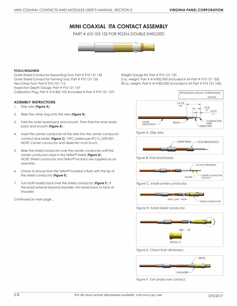
mInI CoAxIAl ItA ContACt AssemblyPART # 610 103 152 FOR RG316 DOUbLE SHIELDED
Assembly InstRuCtIons1. Strip wire (figure A).
2. Slide the crimp ring onto the wire (figure b).
3. Fold the outer braid back and smooth. Then fold the inner braid back and smooth (figure b).
4. Insert the center conductor of the wire into the center conductor contact and solder (figure C). vPC solders per IPC’S J-STD-001.NOTE: Center conductor and dielectric must touch.
5. Slide the shield conductor over the center conductor until the center conductor stops in the Tefl on® shield (figure d).NOTE: Shield conductor and Tefl on® insulator are supplied as an assembly.
6. Check to ensure that the Tefl on® insulator is fl ush with the tip of the shield conductor (figure e).
7. Turn both braids back over the shield conductor (figure f). If the braid extends beyond shoulder, trim braid back to face of shoulder.
Continued on next page...
tools ReQuIRedOuter Shield Conductor Expanding Tool, Part # 910 121 142Outer Shield Conductor Forming Tool, Part # 910 121 126Hex Crimp Tool, Part # 910 101 115Inspection Depth Gauge, Part # 910 121 157Calibration Plug, Part # 414 855 103 (included in Part # 910 121 157)
Weight Gauge Kit, Part # 910 121 1553 oz. weight, Part # 414 852 000 (included in kit Part # 910 121 155)20 oz. weight, Part # 414 853 000 (included in kit Part # 910 121 155)
.17[4.31].37
[9.4].66
[16.76]
BRAIDDIELECTRIC
CONDUCTORWIREINSULATION
OUTER
CRIMP RING FOLD BRAID BACK
NO GAP PERMISSIBLE
SOLDERCENTER CONDUCTOR CONTACT
SMALL GAPSHIELD CONDUCTOR
A
.00
DETAIL A
BRAID
SHOULDER
Figure A. Strip wire.
Figure B. Fold braid back.
Figure C. Install center conductor.
Figure D. Install shield conductor.
Figure E. Check fl ush dimension.
Figure F. Turn braid over contact.
Dimensions shown: [millimeters] inches

MINI COAXIAL CONTACTS AND MODULES USER’S MANUAL: SECTION 2 vIRgInIA pAnel CoRpoRAtIon
5/9/20172-9 For the most current information available, visit www.vpc.com.
Assembly InstRuCtIons, ContInued8. Slide the crimp ring over the braid and shield conductor (figure g).
Do not crimp.
9. Calibrate the Inspection Depth Gauge, Part # 910 121 157 (figure H) by loosening the dial face retaining screw until the dial face allows itself to be turned. Insert the Calibration Plug, Part # 414 855 103 into base of gauge. While keeping constant pressure on the plug, adjust the dial by rotating it such that the pointer points to “0.” Re-tighten retaining screw. Adjust locating markers to “20” and “90.”
10. Check the .01" [.25 mm] dimension (figure H) with the inspection depth gauge. Push the contact onto the pressure plunger of the gauge. After attaining a positive stop and while holding fi rm pressure, push the plunger on top of the dial (to push collar over Tefl on), read the dial on the gauge. If the pointer measures between “20” and “90,” go to step 11. If the pointer is out of the range, repeat steps 1-10.
11. To ensure proper crimp position, slide shield conductor over the locator pin (figure J). Crimp using the Hex Crimp Tool, Part # 910 101 115 (figure K) in hex position “A” (figure J). Wire must not be allowed to pull on the center conductor during crimping (for example, long wire hanging down to fl oor).
Continued on next page...
Figure G. Crimp ring.
Figure K. Hex Crimp Tool, part # 910 101 115.
SHIELD CONDUCTOR
CRIMP RING
Figure H. Inspection Depth Gauge, part # 910 121 157.
Figure J. Crimp positions.
LOCATORPOSITION "A"
mInI CoAxIAl ItA ContACt AssemblyPART # 610 103 152 FOR RG316 DOUbLE SHIELDED
INSPECTION DEPTH GAUGE
[.25].01
DETAIL A A
Figure K. Hex Crimp Tool, part # 910 101 115.
LOCATOR
MINI COAXIAL CONTACTS AND MODULES USER’S MANUAL: SECTION 2 vIRgInIA pAnel CoRpoRAtIon
5/9/20172-10 For the most current information available, visit www.vpc.com.
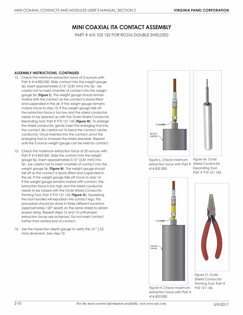
Assembly InstRuCtIons, ContInued12. Check the minimum extraction force of 3 ounces with
Part # 414 852 000. Slide contact into the weight gauge tip. Insert approximately 0.15” [3.81 mm] into tip - be careful not to insert chamfer of contact into the weight gauge tip (figure l). The weight gauge should remain mated with the contact as the contact is slowly lifted and suspended in the air. If the weight gauge remains mated move to step 13. If the weight gauge falls off, the extraction force is too low and the shield conductor needs to be opened up with the Outer Shield Conductor Expanding Tool, Part # 910 121 142 (figure m). To enlarge the shield conductor, gently insert the enlarging tool into the contact. be careful not to bend the contact center conductor. Once inserted into the contact, pivot the enlarging tool to increase the shield diameter. Repeat until the 3 ounce weight gauge can be held by contact.
13. Check the maximum extraction force of 20 ounces with Part # 414 853 000. Slide the contact into the weight gauge tip. Insert approximately 0.15” [3.81 mm] into tip - be careful not to insert chamfer of contact into the weight gauge tip (figure n). The weight gauge should fall off as the contact is slowly lifted and suspended in the air. If the weight gauge falls off move to step 14. If the weight gauge remains mated with contact, the extraction force is too high and the shield conductor needs to be closed with the Outer Shield Conductor Forming Tool, Part # 910 121 126 (figure o). Squeezing the tool handles will reposition the contact legs. This procedure should be done in three different locations (approximately 120° apart) on the same shield to obtain proper sizing. Repeat steps 12 and 13 until proper extraction forces are achieved. Do not insert contact further than slotted end of contact.
14. Use the inspection depth gauge to verify the .01” [.25 mm] dimension. See step 10.
Figure L. Check minimum extraction force with Part # 414 852 000.
Figure N. Check maximum extraction force with Part # 414 853 000.
Figure M. Outer Shield Conductor Expanding Tool, Part # 910 121 142.
Figure O. Outer Shield Conductor Forming Tool, Part # 910 121 126.
mInI CoAxIAl ItA ContACt AssemblyPART # 610 103 152 FOR RG316 DOUbLE SHIELDED

MINI COAXIAL CONTACTS AND MODULES USER’S MANUAL: SECTION 2 vIRgInIA pAnel CoRpoRAtIon
5/9/20172-11 For the most current information available, visit www.vpc.com.
tools ReQuIRedCrimp Tool, Part # 910 101 118Crimp Tool, Part # 910 101 115Crimp Locator, Part # 910 104 128
CRImp tool setup1. Set up the Crimp Tool, Part # 910 101 118 (figure A), by
loosening the latch locking screw (counter-clockwise, until turning stops). Remove any previously used locator.
2. Insert the open end of the Crimp Contact Locator, Part # 910 104 128 (figure b) into the locator retainer. Slide the retaining latch toward the locator until it is securely locked into place. The locator may have to be twisted to allow the latch to retain it. Tighten the latch locking screw.
Assembly InstRuCtIons1. Select correct crimp setting for gauge wire to be used. See
Table below. While in closed position, check diameter of the crimp tool with gauge pins to be sure setting is correct. This should be done periodically during use to compensate for wear. For more information about gauge pins, visit vpc.com/gaugepins. See calibration instructions for Part # 910 101 102/103 for pin gauge verification instructions.
2. Untwist 2” [50.8 mm] of twisted wire. Cut 0.5” [12.7 mm] off the white wire and strip white wire 0.160” [4.06 mm] (figure C).
3. Slide 1/16 [1.58 mm] shrink tubing 0.25” [6.35 mm] long over white wire. Slide crimp ring over both wires (smaller end first) (figure d).
4. Insert wire with center conductor in place at depth allowed by locator into Crimp Tool, Part # 910 101 118 (figure b) and close crimp tool handles completely until handles release. Remove crimped center conductor, shield body and wire. Gently pull on wire to ensure proper crimp.
...continued on next page
CRImp settIngs
mInI CoAxIAl ItA ContACt AssemblyPART # 610 103 161 FOR 24 & 26 TWISTED PAIR / 610 103 184 FOR 22 AWG TWISTED PAIR
wIRe gAuge
mAx.(in [mm])
mIn.(in [mm])
pullout foRCe (lbs [n])
26 0.032 [0.81] 0.028 [0.71] 2 [8.89]
24 0.039 [9.91] 0.035 [8.89] 2 [8.89]
22 0.037 [9.39] 0.033 [8.38] 2 [8.89]
Figure D. Crimp ring and shrink tubing.
CRIMP RING SHRINK TUBING
[50.8]2.00 REF.
[4.06].16
[12.7].50
CRIMP LOCATION SHIELD CONDUCTOR
Figure B. Locator, Part # 910 104 128.
Figure C. Cut and strip wire.
Figure E. Install shield conductor.
Dimensions shown: [millimeters] inches
Figure A. Crimp Tool, Part # 910 101 118.
MICROCRIMP ADJUSTING KNOb
MICROCRIMP INDICATOR
LATCH ASSEMbLy AND LOCKING SCREW
CONTACT LOCATOR DIE
INDENTER OPENING
↓

MINI COAXIAL CONTACTS AND MODULES USER’S MANUAL: SECTION 2 vIRgInIA pAnel CoRpoRAtIon
5/9/20172-12 For the most current information available, visit www.vpc.com.
Assembly InstRuCtIons, ContInued5. Slide shrink tubing over crimped area so that it covers all
exposed areas of center conductor and touches dielectric. Heat to shrink (figure f).
6. Re-twist black wire around white conductor and shield. Trim excess wire that extends beyond the shoulder of the shield conductor. Strip black wire such that insulation still covers shrink tubing but not crimp area on shield. Unravel and fl are strands around shield (figure g).
7. To ensure proper crimp position, slide shield conductor over the locator pin. Crimp using the Hex Crimp Tool, Part # 910 101 115 (figure H) in hex position “A” for the larger side and hex position “b” for the smaller end (figure J). Wire must not be allowed to pull on the center conductor during crimping (for example, long wire hanging down to fl oor).
mInI CoAxIAl ItA ContACt AssemblyPART # 610 103 161 FOR 24 & 26 AWG TWISTED PAIR / 610 103 184 FOR 22 AWG TWISTED PAIR
Figure F. Shrink tubing.
SHRINK TUBING
Figure G. Apply crimp ring.
CUT BLACK WIRE HERE ANDTRIM STRANDS AFTER UNRAVELING
UNRAVEL STRANDS TO FLAREAROUND SHIELD
SHOULDER
Figure H. Crimp tool, Part # 910 101 115.
Figure J. Crimp locations.POSITION "A"POSITION "B"
Dimensions shown: [millimeters] inches
LOCATOR
MINI COAXIAL CONTACTS AND MODULES USER’S MANUAL: SECTION 2 vIRgInIA pAnel CoRpoRAtIon
5/9/20172-13 For the most current information available, visit www.vpc.com.
tools ReQuIRedSolder Kit, includes Holding Fixture and Adapter, Part # 910 121 144Adapter (for those who already own a holding fi xture), Part # 910 121 149Steinel Heat Gun with nozzle, Part # 910 121 160 - 110v or Part # 910 121 167 - 220v
Assembly InstRuCtIons1. Strip wire (figure A).
2. Straighten the center conductor making sure the stranded center conductor is twisted into its original lay.
3. Tin stranded center conductor with Sn63 solder per QQ-S-571. Use RMA fl ux per MIL-F-14256 (Alpha #611 or equivalent).
4. Make sure the shield braid is trimmed evenly and no loose strands are extending out across the exposed dielectric or cable jacket.
5. Smooth the braid ends fl at against the cable dielectric.
6. Slide the contact over the end of the prepared cable, and carefully push the contact onto the cable until it stops. Rotating the contact slightly during cable insertion will help prevent the braid from catching.
7. Inspect for proper insertion (figure b). The center conductor must be visible through one of the forward inspection windows. The distance from the rear of the contact outer body to the cable jacket insulation should be .015” [0.38 mm].
8. Install the Adapter, Part # 910 121 149, onto the Holding fi xture, Part # 910 121 144 (figure C). Insert a contact in the adapter side marked “P” for pin, and set up the dimensions (figure C).
9. Insert the contact/cable assembly into the adapter. Clamp the cable in the holding fi xture. The cable must remain fully inserted in the contact and the contact must be fully inserted in the adapter, for the adapter to act as a heat sink. The cable must be straight between the contact and the cable clamp.
10. Attach the appropriate refl ector to the heating tool. See instruction sheet accompanying heat gun for instructions and safety precautions.
11. Using the holding fi xture, position the contact in the heating tool refl ector, with the forward inspection window centered in the refl ector. Continue heating until the small solder preform in the forward inspection window has melted and fl owed. The large solder preform in the ear inspection window should have melted and fl owed by this time. If it has not, direct hot air at the rear inspection window until it does.
12. If contact is UNDERHEATED, there will be visible remnants of the original shapes of the solder preforms. An underheated contact must be re-heated. If contact is OVERHEATED, solder will wick away from the joint areas, leaving no solder fi llets. An overheated contact must be removed and a new contact installed.
13. After the contact has cooled for at least 10 seconds, remove the contact and cable from the holding fi xture.
14. Inspect the completed termination for correct assembly. The cable shield must extend into the contact at least as far as the front edge of the rear inspection windows. The center conductor must be visible through one of the forward inspection windows.
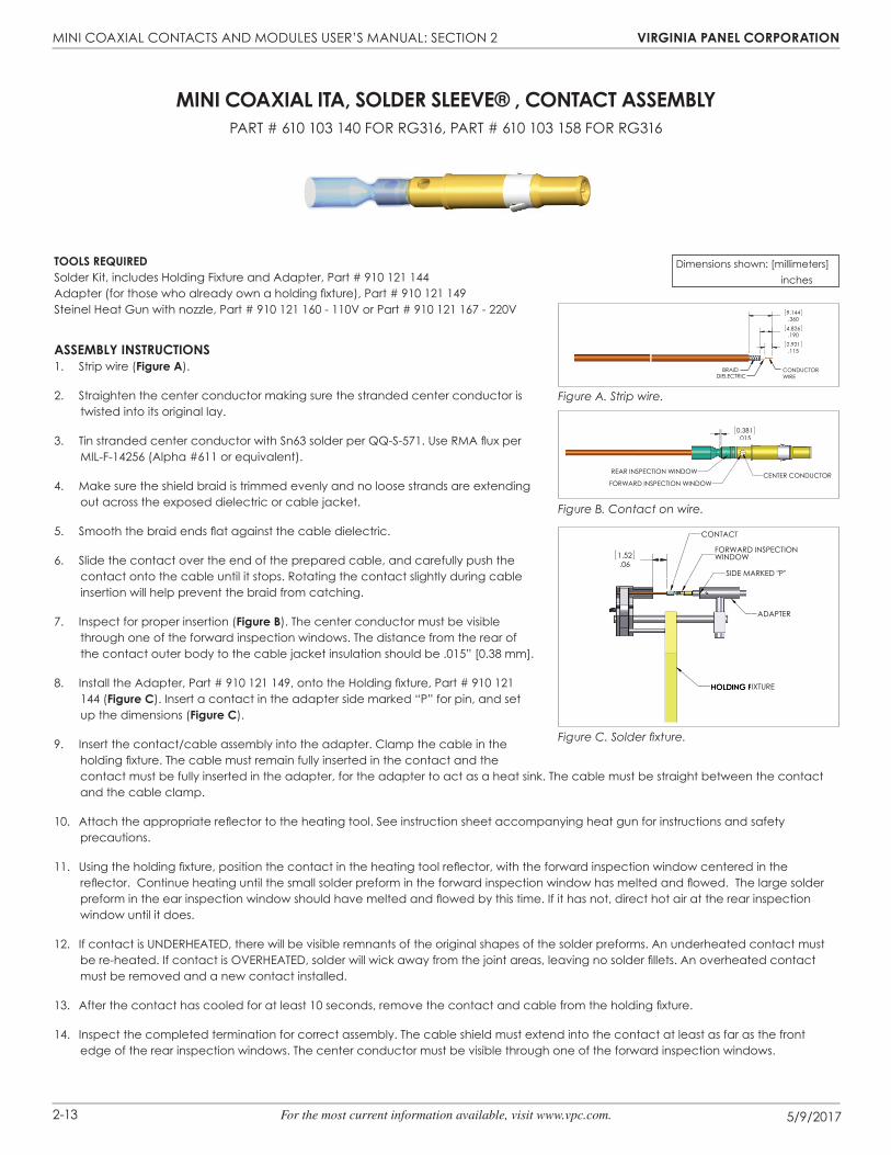
mInI CoAxIAl ItA, soldeR sleeve® , ContACt AssemblyPART # 610 103 140 FOR RG316, PART # 610 103 158 FOR RG316
Figure A. Strip wire.
Figure B. Contact on wire.
Figure C. Solder fi xture.
.3609.144
.1152.921.1904.826
CONDUCTORWIREDIELECTRIC
BRAID
.0150.381
CENTER CONDUCTORFORWARD INSPECTION WINDOW
REAR INSPECTION WINDOW
Dimensions shown: [millimeters] inches
.061.52
SIDE MARKED "P"
FORWARD INSPECTIONWINDOW
ADAPTER
CONTACT
HOLDING FIXTURE

MINI COAXIAL CONTACTS AND MODULES USER’S MANUAL: SECTION 2 vIRgInIA pAnel CoRpoRAtIon
5/9/20172-14 For the most current information available, visit www.vpc.com.
tools ReQuIRedSolder Kit, includes Holding Fixture and Adapter, Part # 910 121 144Adapter (for those who already own a holding fi xture), Part # 910 121 149Steinel Heat Gun with nozzle, Part # 910 121 160 - 110v or Part # 910 121 167 - 220v
Assembly InstRuCtIons1. Strip wire (figure A).
2. Straighten the center conductor making sure the stranded center conductor is twisted into its original lay.
3. Tin stranded center conductor with Sn63 solder per QQ-S-571. Use RMA fl ux per MIL-F-14256 (Alpha #611 or equivalent).
4. Fold the center conductor back on itself (figure b).
5. Make sure the shield braid is trimmed evenly and no loose strands are extending out across the exposed dielectric or cable jacket.
6. Smooth the braid ends fl at against the cable jacket.
7. Slide the contact over the end of the prepared cable, and carefully push the contact onto the cable until it stops. Rotating the contact slightly during cable insertion will help prevent the braid from catching.
8. Inspect for proper insertion (figure C). The center conductor must be visible through one of the forward inspection windows. The distance from the rear of the contact outer body to the cable jacket insulation should be .015” [0.38 mm].
9. Install the Adapter, Part # 910 121 149, onto the Holding Fixture, Part # 910 121 144 (figure d). Insert a contact in the adapter side marked “P” for pin, and set up the dimensions (figure d).
10. Insert the contact/cable assembly into the adapter. Clamp the cable in the holding fi xture. The cable must remain fully inserted in the contact and the contact must be fully inserted in the adapter for adapter to act as a heat sink. The cable must be straight between the contact and the cable clamp.
11. Attach the appropriate refl ector to the heating tool. See instruction sheet accompanying heat gun for instructions and safety precautions.
12. Using the holding fi xture, position the contact in the heating tool refl ector, with the forward inspection window centered in the refl ector. Continue heating until the small solder preform in the forward inspection window has melted and fl owed. The large solder preform in the rear inspection window should have melted and fl owed by this time; if it has not, direct hot air at the rear inspection window until it does.
13. If contact is UNDERHEATED, there will be visible remnants of the original shapes of the solder preforms. An underheated contact must be re-heated. If contact is OVERHEATED, solder will wick away from the joint areas, leaving no solder fi llets. An overheated contact must be removed and a new contact installed.
14. After the contact has cooled for at least 10 seconds, remove the contact and cable from the holding fi xture.
15. Inspect the completed termination for correct assembly. The cable shield must extend into the contact at least as far as the front edge of the rear inspection windows. The center conductor must be visible through one of the forward inspection windows.
mInI CoAxIAl ItA, soldeR sleeve® , ContACt AssemblyPART # 610 103 140 FOR RG178, PART # 610 103 158 FOR RG178
Figure A. Strip wire.
Figure B. Fold center conductor.
Figure C. Contact on wire.
.150±.0153.81.290±.015
7.36
DIELECTRICBRAID
.215±.0155.46±0.38
CONDUCTORWIRE
.0150.381
CENTER CONDUCTOR
FORWARD INSPECTION WINDOW
REAR INSPECTION WINDOW
Figure D. Solder fi xture.
Dimensions shown: [millimeters] inches
.061.52
SIDE MARKED "P"
FORWARD INSPECTIONWINDOW
ADAPTER
CONTACT
HOLDING FIXTURE

MINI COAXIAL CONTACTS AND MODULES USER’S MANUAL: SECTION 3 vIRgInIA pAnel CoRpoRAtIon
5/9/20173-1 For the most current information available, visit www.vpc.com.
tools ReQuIRedWire Stripping ToolWire-wrap gunWire-wrap bit
Assembly InstRuCtIonsNOTE: VPC performs wire-wrap terminations in accordance with IPC-A-620
standards.
NOTE: Wire-wraps must be performed with solid wire. Stranded wire will not work for wire wrapping. VPC recommends 26 to 30 AWG wire.
1. Cut and strip the wire. Depending on the style of wire-wrap gun and bit used, the wire is either stripped during the wrapping process or needs to be stripped before the wrapping process.
NOTE: Refer to the user manual of your wire-wrap gun to determine in which fashion your tool operates.
2. Insert the wire into the wire slot on the wire-wrap gun. With modified and standard bits insert the wire in the wire slot as deep as possible. With C.S.W. bits the wire has to be inserted all the way through the wire slot until it goes out of the cutting window. The simplified sleeve of the manual tool has no notch.
3. Hold the wire in place by hand (figure A).
4. Position the terminal hole of the wire-wrap gun on the post to be wrapped. The wire-wrap gun should be parallel with the contact. The wire must continue to be held in place by hand.
5. Engage the wire-wrap gun to wrap the wire. During the wrapping operation, gently press the tool forward onto the wire-wrap post. The turns of the connection have to be nicely wrapped against the other. Do not push too hard. Do not pull backwards.
mInI CoAxIAl wIRe-wRAp ContACt teRmInAtIonPART # 610 104 140 (RECEIvER), 610 103 129 (ITA)
Figure A. Wire wrap gun with wire.
Figure B. Completed wrapped wire.

MINI COAXIAL CONTACTS AND MODULES USER’S MANUAL: SECTION 4 vIRgInIA pAnel CoRpoRAtIon
5/9/20174-1 For the most current information available, visit www.vpc.com.
mInI CoAxIAl ReCeIveR ContACt InstAllAtIon And RemovAlPART # 510 104 120 & 510 104 150
Figure B. Extraction Tool, Part # 910 112 104.
Figure A. Module Cap Alignment Diagram.
tools ReQuIRed0.050” Allen WrenchFlat Head ScrewdriverPhillips Screwdriver for iCon modulesMini Power/Mini Coaxial Extraction Tool, Part # 910 112 104
ContACt InstAllAtIon InstRuCtIons 1. Assemble the contact to the respective wire.
NOTE: For more information concerning the contact assembly process, see contact assembly instructions in Section 1 of this User’s Manual.
2. Insert the assembled contact into the back (wiring side) of the assembled module. The contact can only go into one side. Ensure that the contact is squared up with the corresponding module location.
3. Once in place, pull the wire slightly to ensure that the contact is seated.
ContACt RemovAl InstRuCtIons1. Remove the module from the receiver frame.
NOTE: For more information concerning the process of removing the module from the receiver frame, see module installation and removal instructions in Section 5 of this User’s Manual.
2. Use the 0.050" Allen wrench to remove the module cap screws located at the top, middle and bottom of the module (figure b).
3. Grasp the module halves and apply force in opposite directions, rocking the ends of the module while slightly pulling the module cap away from the mating bottom section. be sure to open both sides of the module simultaneously or contacts could be damaged.
4. Place the Mini Power/Mini Coaxial Extraction Tool, part # 910 112 104 (figure C), over the contact to be removed/replaced. Use care to keep the tool perpendicular to the surface of the module, otherwise the tool or contact could be damaged.
5. Once the extraction tool is seated and the retaining ring tabs on the contact are compressed, push the plunger. The contact will be pushed out of the rear of the module.
6. For 19 and 76 position modules, do not tighten screws. Insert an ITA contact in positions 2 and 18 or 2A and 18A (for 76 position modules) to properly align the module cap. With the ITA contacts in place, tighten the module cap screws. Do not over-tighten screws; screw torque limit is 13 +/- 1 in-oz.
For all other modules, replace the module cap (figure A) using both hands to push the separated halves together. Replace and tighten the module cap screws to a maximum torque of 2 in-lbs [0.23 Nm].
do not pusH tHe tool Into tHe module untIl tHe tIp of tHe extRACtIon tool HAs been fully seAted Into tHe module And CompRessed tHe RetAInIng RIng tAbs on tHe ContACt.
NOTE: The process shown here uses standard/90 series modules. The same process is used for modules from other series.
NOTE: If you are using a hybrid module, you may need to reference the User’s Manual for the other contact type for extraction instructions. Figure C. Be sure to keep the tool perpendicular so as to
avoid bent pins.

MINI COAXIAL CONTACTS AND MODULES USER’S MANUAL: SECTION 4 vIRgInIA pAnel CoRpoRAtIon
5/9/20174-2 For the most current information available, visit www.vpc.com.
mInI CoAxIAl ReCeIveR ContACt InstAllAtIon And RemovAlPART # 510 104 243 & 510 104 301
Figure A. Contacts inserted into the module.
tools ReQuIRed0.050” Allen WrenchFlat Head ScrewdriverPhillips Screwdriver for iCon modulesMini Coaxial Extraction Tool, Part # 910 112 104
ContACt InstAllAtIon InstRuCtIons 1. Assemble the contact to the respective wire.
NOTE: For more information concerning the contact assembly process, see contact assembly instructions in Section 1 of this User’s Manual.
2. Insert the assembled contact into the back (wiring side) of the assembled module. The contact can only go into one side. Ensure that the contact is squared up with the corresponding module location. Once in place, pull the wire slightly to ensure that the contact is seated.
ContACt RemovAl InstRuCtIons1. Remove the module from the receiver frame.
NOTE: For more information concerning the process of removing the module from the receiver frame, see module installation and removal instructions in Section 5 of this User’s Manual.
2. Use a 5/64 Allen wrench or Phillips head screwdriver to remove the two 2-56 screws located at the top and bottom of the module (figure b).
3. Grasp the module halves and apply force in opposite directions, rocking the ends of the module while slightly pulling the top of the module away from the bottom section. be sure to open both sides of the module simultaneously or contacts could be damaged.
4. Place the Mini Coaxial Extraction Tool, Part # 910 112 104 (figure C), over the contact to be removed/ replaced. Use care to keep the tool perpendicular to the surface of the module, otherwise the tool or the contact could be bent.
5. Once the extraction tool is seated and the retaining tab on the contact are compressed, press the tool into the module. The contact will be pushed out of the rear of the module.
do not pRess tHe tool Into tHe module untIl tHe tIp of tHe extRACtIon tool HAs fully seAted Into tHe module And CompRessed tHe RetAInIng RIng tAb on tHe ContACt.
6. On the opposite side of the module from the extraction tool, grasp the contact and hold it while removing the extraction tool. This will prevent the contact from being pulled back into the module while the tool is being removed.
7. Replace the module cap using both hands to push the separated halves together. Replace and tighten the module retaining screws to a maximum torque of 1.5 in-lbs [0.16 Nm].
NOTE: The process shown here uses standard/90 series modules. The same process is used for modules from other series.
NOTE: If you are using a hybrid module, you may need to reference the User’s Manual for the other contact type for extraction instructions.
RETAINING TAB
MINI COAXIAL PATCHCORD
B
EXTRACTIONTOOL
Figure B. Open both sides of the module simultaneously or pins could be damaged.
Figure C. Ensure that the tool is kept perpendicular to the module face to avoid damage to the contact or tool.
MODULE MOUNTING SCREW MODULE MOUNTING SCREW
2-56 SCREW 2-56 SCREW

MINI COAXIAL CONTACTS AND MODULES USER’S MANUAL: SECTION 4 vIRgInIA pAnel CoRpoRAtIon
5/9/20174-3 For the most current information available, visit www.vpc.com.
tools ReQuIRedMini Coaxial Extraction Tool, Part # 910 112 104
ContACt InstAllAtIon InstRuCtIons1. Assemble the contact to the respective wire.
NOTE: For more information concerning the contact assembly process, see contact assembly instructions in Section 2 of this User’s Manual.
2. Insert the assembled contact into the back (wiring side) of the module. Push the contact forward until the crimp is inside the module housing. Once in place, pull the wire slightly to ensure the contact is seated.
ContACt RemovAl InstRuCtIons1. Remove the module from the ITA frame.
NOTE: For more information concerning the process of removing the module from the ITA frame, see module installation and removal instructions in Section 5 of this User’s Manual.
2. Place the Mini Power/Mini Coaxial Extraction Tool, part # 910 112 104 (figure A) over the contact to be removed/replaced. Use care to keep the tool perpendicular to the surface of the module, otherwise the tool or contact could be damaged. Rotate the tool slightly while pushing it into the counter bore on the mating side of the module.
3. Once the extraction tool is seated properly and the retaining ring tabs on the contact are compressed, push the tool into the module. The contact will be pushed out of the rear of the module (figure b).
do not pusH tHe tool Into tHe module untIl tHe tIp of tHe extRACtIon tool HAs been fully seAted Into tHe module And CompRessed tHe RetAInIng RIng tAbs on tHe ContACt.
NOTE: The process shown here uses standard/90 series modules. The same process is used for modules from other series.
NOTE: If you are using a hybrid module, you may need to reference the User’s Manual for the other contact type for extraction instructions.
mInI CoAxIAl ItA ContACt InstAllAtIon And RemovAl
Figure B. Be sure to keep the tool perpendicular to avoid bent pins.
Figure A. Extraction Tool, Part # 910 112 104.

MINI COAXIAL CONTACTS AND MODULES USER’S MANUAL: SECTION 5 vIRgInIA pAnel CoRpoRAtIon
5/9/20175-1 For the most current information available, visit www.vpc.com.
tools ReQuIRed
3/32 Allen Wrench
InstAllAtIon InstRuCtIons1. Place the module in the receiver or ITA until the upper and
lower module screws touch the mating holes in the inner frame. Ensure that Position 1 is located at the top for systems in which the modules are oriented vertically or to the left for systems in which the modules are oriented horizontally.
2. Using a 3/32 Allen wrench, tighten the top screw 1 to 2 full revolutions, while pushing lightly against the face of the module.
3. Maintain this pressure while tightening the bottom screw 1 to 2 full revolutions.
4. Repeat this sequence until the module is seated. Torque the screw to 4 in-lbs [0.45 Nm].
RemovAl InstRuCtIons1. To remove, loosen the top screw 1 to 2 full revolutions. Loosen
bottom screw 1 to 2 full revolutions.
2. Repeat this sequence until the module is separated from the receiver or ITA.
NOTE: For optimum performance and system longevity, distribute the contact load evenly throughout the module.
mInI CoAxIAl stAndARd/90 seRIes module InstAllAtIon And RemovAl
Figure A. Receiver Module.
Figure B. ITA Module.
POSITION 1

MINI COAXIAL CONTACTS AND MODULES USER’S MANUAL: SECTION 5 vIRgInIA pAnel CoRpoRAtIon
5/9/20175-2 For the most current information available, visit www.vpc.com.
tools ReQuIRedPhillips Head Screwdriver
InstAllAtIon InstRuCtIonsNOTE: The receiver strain relief plate or the ITA cover may need to be
removed prior to installing or removing an iCon module. Please refer to the appropriate User’s Manual for instructions on how to perform these steps.
1. Place the module in the receiver or ITA until the upper and lower module screws touch the mating holes in the inner frame. Install modules such that Position 1 is located at the top of the ITA/receiver frame.
2. Using a Phillips head screwdriver, tighten the top screw 1 to 2 full revolutions, while pushing lightly against the face of the module.
3. Maintain this pressure while tightening the bottom screw 1 to 2 full revolutions.
4. Repeat this sequence until the module is seated. Torque the screw to 1.5 in-lbs [0.16 Nm].
RemovAl InstRuCtIons1. To remove, loosen the top screw 1 to 2 full revolutions. Loosen
bottom screw 1 to 2 full revolutions.
2. Repeat this sequence until the module is separated from the receiver or ITA.
NOTE: For optimum performance and system longevity, distribute the contact load evenly throughout the module.
mInI CoAxIAl ICon module InstAllAtIon And RemovAl
Figure A. Receiver Module.
Figure B. ITA Module.

MINI COAXIAL CONTACTS AND MODULES USER’S MANUAL: SECTION 6 vIRgInIA pAnel CoRpoRAtIon
5/9/20176-1 For the most current information available, visit www.vpc.com.
CRoss RefeRenCe tAbles
ReCeIveR ContACts
stAn
dARd
/ 90
seR
Ies
ReC
eIve
R m
odu
les
ICo
n Re
CeI
veR
mo
dule
s
CAs
s/
80 s
eRIe
s Re
CeI
veR
mo
dule
s
CRIm
p to
ol
extR
ACtIo
n
mIs
C.
510
104
120
510
104
150
510
104
243
510
160
102
510
160
103
510
160
104
510
113
121
510
113
122
910
101
115
910
112
104
910
121
119
910
121
131
910
121
143
910
121
144
910
121
149
910
121
156
910
121
160
910
121
167
610 104 114 X X X X X X X X X X X X X X
610 104 140 X X X X X X X X X X X
610 104 141 X X X X X X X X X X X X X X
610 104 142 X X X X X X X X X X X X X X X
610 104 149 X X X X X X X X X X X
610 104 154 X X X X X X X X X X
ItA ContACts
stAn
dARd
/ 90
seR
Ies
ItA
mo
dule
s
ICo
n ItA
m
odu
les
CAs
s/ 8
0 se
RIes
ItA
mo
dule
s
CRIm
p to
ols
loCA
toR
extR
ACtIo
n
mIs
C.
510
108
111
510
108
132
510
108
210
510
161
102
510
161
103
510
161
104
510
114
108
510
114
109
910
101
115
910
101
118
910
104
128
910
112
104
910
121
126
910
121
142
910
121
144
910
121
149
910
121
155
910
121
157
910
121
160
910
121
167
610 103 115 X X X X X X X X X X X X X X
610 103 130 X X X X X X X X X X X X X X
610 103 136 X X X X X X X X X X X X X
610 103 140 X X X X X X X X X X X X X X X X X
610 103 152 X X X X X X X X X X X X
610 103 157 X X X X X X X X X X X X X X
610 103 158 X X X X X X X X X X X X X
610 103 161 X X X X X X X X X X X X X X
610 103 166 X X X X X X X X X X X
610 103 172 X X X X X X X X X
610 113 146 X X X X X X X X X X X X X X