section 6 - 4donline.ihs.com · smb slide-on (subglis) ... viit and enter te art nmer. smb general...
TRANSCRIPT

Our Most Important Connection is with You.™
SMB / SMB-LOCK / SMC
SECT
ION
6
R114 / R117 / R112

6-3
Our Most Important Connection is with You.™
Go online for data sheets & assembly instructions. Visit www.radiall.com and enter the part number.
SMB
Introduction . . . . . . . . . . . . . . . . . . . . . . . . . . . . . . . . . . . . . . . . . . . . . . . . . . . . . . . . . . . . . . . . . . . . . . . . . . . . . . . . . . . . . . . . . . . . . . . . . . . . . . . . . . . . . . 6-4 to 6-5Interface . . . . . . . . . . . . . . . . . . . . . . . . . . . . . . . . . . . . . . . . . . . . . . . . . . . . . . . . . . . . . . . . . . . . . . . . . . . . . . . . . . . . . . . . . . . . . . . . . . . . . . . . . . . . . . . . . . . . . . . . . 6-6Characteristics . . . . . . . . . . . . . . . . . . . . . . . . . . . . . . . . . . . . . . . . . . . . . . . . . . . . . . . . . . . . . . . . . . . . . . . . . . . . . . . . . . . . . . . . . . . . . . . . . . . . . . . . . 6-7 to 6-8Plugs . . . . . . . . . . . . . . . . . . . . . . . . . . . . . . . . . . . . . . . . . . . . . . . . . . . . . . . . . . . . . . . . . . . . . . . . . . . . . . . . . . . . . . . . . . . . . . . . . . . . . . . . . . . . . . . . . . . . 6-8 to 6-11Jacks . . . . . . . . . . . . . . . . . . . . . . . . . . . . . . . . . . . . . . . . . . . . . . . . . . . . . . . . . . . . . . . . . . . . . . . . . . . . . . . . . . . . . . . . . . . . . . . . . . . . . . . . . . . . . . . . . . 6-10 to 6-12Bulkhead jacks . . . . . . . . . . . . . . . . . . . . . . . . . . . . . . . . . . . . . . . . . . . . . . . . . . . . . . . . . . . . . . . . . . . . . . . . . . . . . . . . . . . . . . . . . . . . . . . . . . . . . . . 6-12 to 6-14Receptacles . . . . . . . . . . . . . . . . . . . . . . . . . . . . . . . . . . . . . . . . . . . . . . . . . . . . . . . . . . . . . . . . . . . . . . . . . . . . . . . . . . . . . . . . . . . . . . . . . . . . . . . . . . . 6-14 to 6-15PCB receptacles . . . . . . . . . . . . . . . . . . . . . . . . . . . . . . . . . . . . . . . . . . . . . . . . . . . . . . . . . . . . . . . . . . . . . . . . . . . . . . . . . . . . . . . . . . . . . . . . . . . . . . 6-15 to 6-16Adapters . . . . . . . . . . . . . . . . . . . . . . . . . . . . . . . . . . . . . . . . . . . . . . . . . . . . . . . . . . . . . . . . . . . . . . . . . . . . . . . . . . . . . . . . . . . . . . . . . . . . . . . . . . . . . . . . . . . . . . . . 6-17Panel drilling . . . . . . . . . . . . . . . . . . . . . . . . . . . . . . . . . . . . . . . . . . . . . . . . . . . . . . . . . . . . . . . . . . . . . . . . . . . . . . . . . . . . . . . . . . . . . . . . . . . . . . . . . . . . . . . . . . . 6-22Assembly instructions . . . . . . . . . . . . . . . . . . . . . . . . . . . . . . . . . . . . . . . . . . . . . . . . . . . . . . . . . . . . . . . . . . . . . . . . . . . . . . . . . . . . . . . . . . . . . . . . . . . . . . . . . 6-22
SMB-LOCK
Introduction . . . . . . . . . . . . . . . . . . . . . . . . . . . . . . . . . . . . . . . . . . . . . . . . . . . . . . . . . . . . . . . . . . . . . . . . . . . . . . . . . . . . . . . . . . . . . . . . . . . . . . . . . . . . . . . . . . . . 6-18Interface . . . . . . . . . . . . . . . . . . . . . . . . . . . . . . . . . . . . . . . . . . . . . . . . . . . . . . . . . . . . . . . . . . . . . . . . . . . . . . . . . . . . . . . . . . . . . . . . . . . . . . . . . . . . . . . . . . . . . . . . 6-18Characteristics . . . . . . . . . . . . . . . . . . . . . . . . . . . . . . . . . . . . . . . . . . . . . . . . . . . . . . . . . . . . . . . . . . . . . . . . . . . . . . . . . . . . . . . . . . . . . . . . . . . . . . . . . . . . . . . . . 6-19Plugs . . . . . . . . . . . . . . . . . . . . . . . . . . . . . . . . . . . . . . . . . . . . . . . . . . . . . . . . . . . . . . . . . . . . . . . . . . . . . . . . . . . . . . . . . . . . . . . . . . . . . . . . . . . . . . . . . . . . . . . . . . . 6-20
SMB LIMITED DETENT (SMB-A)
Receptacles . . . . . . . . . . . . . . . . . . . . . . . . . . . . . . . . . . . . . . . . . . . . . . . . . . . . . . . . . . . . . . . . . . . . . . . . . . . . . . . . . . . . . . . . . . . . . . . . . . . . . . . . . . . . . . . . . . . 6-21
SMB SLIDE-ON (SUBGLIS)
Plugs and receptacles . . . . . . . . . . . . . . . . . . . . . . . . . . . . . . . . . . . . . . . . . . . . . . . . . . . . . . . . . . . . . . . . . . . . . . . . . . . . . . . . . . . . . . . . . . . . . . . . . . . . . . . . . 6-21
SMC
Introduction . . . . . . . . . . . . . . . . . . . . . . . . . . . . . . . . . . . . . . . . . . . . . . . . . . . . . . . . . . . . . . . . . . . . . . . . . . . . . . . . . . . . . . . . . . . . . . . . . . . . . . . . . . . . . . . . . . . . 6-23Interface . . . . . . . . . . . . . . . . . . . . . . . . . . . . . . . . . . . . . . . . . . . . . . . . . . . . . . . . . . . . . . . . . . . . . . . . . . . . . . . . . . . . . . . . . . . . . . . . . . . . . . . . . . . . . . . . . . . . . . . . 6-23Characteristics . . . . . . . . . . . . . . . . . . . . . . . . . . . . . . . . . . . . . . . . . . . . . . . . . . . . . . . . . . . . . . . . . . . . . . . . . . . . . . . . . . . . . . . . . . . . . . . . . . . . . . . . . . . . . . . . . 6-24Plugs . . . . . . . . . . . . . . . . . . . . . . . . . . . . . . . . . . . . . . . . . . . . . . . . . . . . . . . . . . . . . . . . . . . . . . . . . . . . . . . . . . . . . . . . . . . . . . . . . . . . . . . . . . . . . . . . . . . . . . . . . . . 6-25Jacks . . . . . . . . . . . . . . . . . . . . . . . . . . . . . . . . . . . . . . . . . . . . . . . . . . . . . . . . . . . . . . . . . . . . . . . . . . . . . . . . . . . . . . . . . . . . . . . . . . . . . . . . . . . . . . . . . . 6-25 to 6-27Receptacles . . . . . . . . . . . . . . . . . . . . . . . . . . . . . . . . . . . . . . . . . . . . . . . . . . . . . . . . . . . . . . . . . . . . . . . . . . . . . . . . . . . . . . . . . . . . . . . . . . . . . . . . . . . 6-27 to 6-28Adapters . . . . . . . . . . . . . . . . . . . . . . . . . . . . . . . . . . . . . . . . . . . . . . . . . . . . . . . . . . . . . . . . . . . . . . . . . . . . . . . . . . . . . . . . . . . . . . . . . . . . . . . . . . . . . . . . . . . . . . . . 6-28Panel drilling . . . . . . . . . . . . . . . . . . . . . . . . . . . . . . . . . . . . . . . . . . . . . . . . . . . . . . . . . . . . . . . . . . . . . . . . . . . . . . . . . . . . . . . . . . . . . . . . . . . . . . . . . . . . . . . . . . . 6-28
SECT
ION
6 T
ABLE
OF
CON
TEN
TS
Contents

6-4
Our Most Important Connection is with You.™
Go online for data sheets & assembly instructions. Visit www.radiall.com and enter the part number.
SMB
GENERAL• Subminiature coaxial connectors• Snap-on coupling• Plugs have female contacts• Jacks have male contacts• Low weight and reduced outline dimensions• Captive contact (except contrary specification)
APPLICABLE STANDARDS• SMB series MIL-C-39012
MIL-C-39012/67-72• IEC 169-10• CECC 22130• BS 9210 N0007
APPLICATIONS• Mobile communication systems• Civil and military telecommunications• Aeronautics• Automotive
50Ω DC - 4 GHz
PROFILE
Unmated Mated
Introduction

6-5
Our Most Important Connection is with You.™
Go online for data sheets & assembly instructions. Visit www.radiall.com and enter the part number.
SMB
SMB snap-on subminiature coaxial connectors provide a fast and reliable connection for high density packaging for applications up to 4 GHz.
Radiall offers a very large range of SMB connectors, including cable plugs and jacks with bulkhead and panel mount configurations, bulkhead and panel mount receptacles; through hole, SMT and edge card receptacles and in-series and between series adapters.
SMB series also features versions with lower mating forces than standard. Four types of interconnection mechanisms are available:
• SMB: Standard snap-on connection The design permits quick engagement and disengagement.
• SMB limited detent (SMB-A): Snap-on connection with low mating force The design permits quick engagement and disengagement, and is suitable for printed circuit boards. Radiall offers a range of PCB and bulkhead receptacles with female center contact. The SMB-A receptacles are completely intermateable with standard SMB jacks.
• SMB slide-on (SUBGLIS): Slide-on connection The design is suitable for back plane and blind mate applications. In this case, we recommend the association of a mobile connector (floating jack / receptacle) with a fixed connector (panel plug / jack, receptacle). The SUBGLIS connectors are completely intermateable with standard SMB and SMB-A connectors and for that, they can be used for test applications.
• SMB Lock: Plugs (with female center contact) have a coupling nut allowing a reliable lock-on connection (50 N min). This range allows a visual control of the locking system.
These four types of SMB connectors have the same electrical performances.
Introduction
6-6
Our Most Important Connection is with You.™
Go online for data sheets & assembly instructions. Visit www.radiall.com and enter the part number.
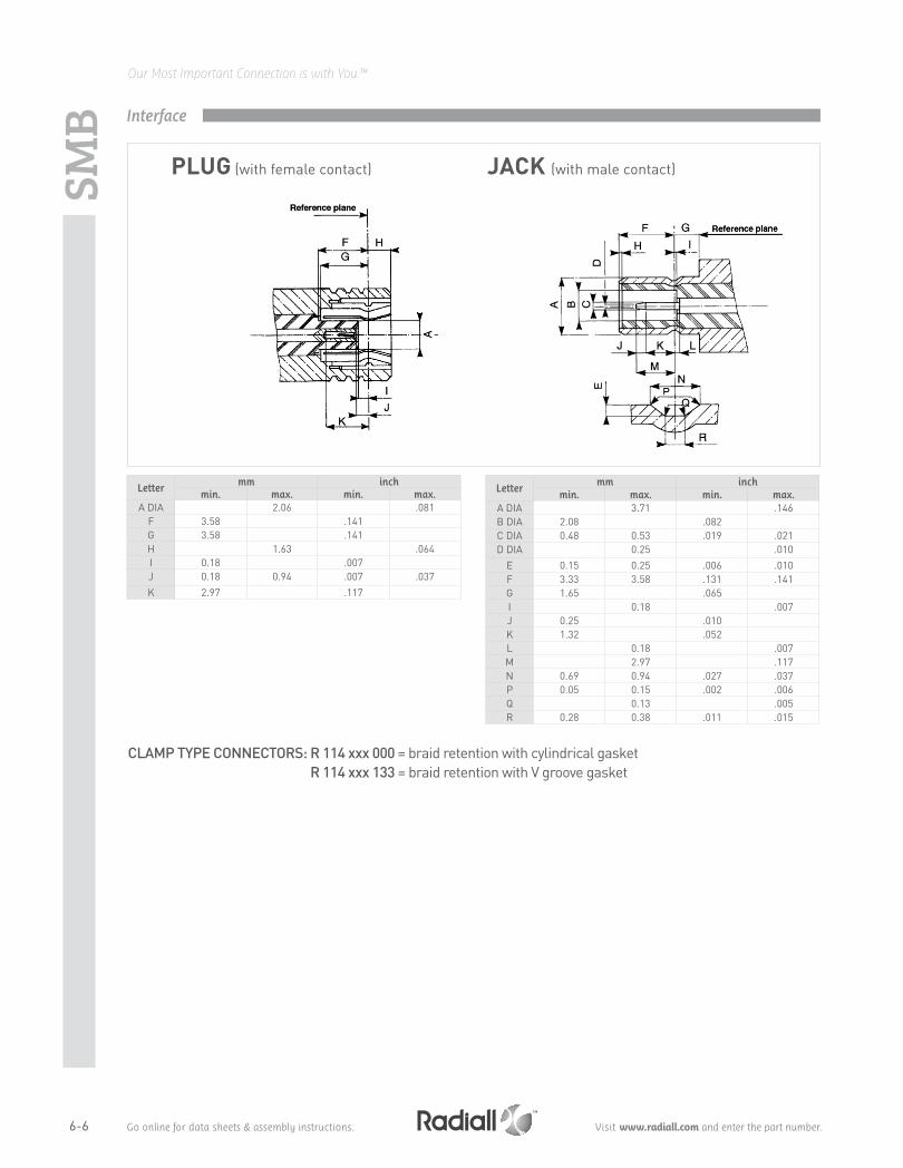
Letter mm inch
min. max. min. max. A DIA 2.06 .081
F 3.58 .141G 3.58 .141H 1.63 .064I 0.18 .007J 0.18 0.94 .007 .037K 2.97 .117
Letter mm inch
min. max. min. max. A DIA 3.71 .146B DIA 2.08 .082C DIA 0.48 0.53 .019 .021D DIA 0.25 .010
E 0.15 0.25 .006 .010F 3.33 3.58 .131 .141G 1.65 .065I 0.18 .007J 0.25 .010K 1.32 .052L 0.18 .007M 2.97 .117N 0.69 0.94 .027 .037P 0.05 0.15 .002 .006Q 0.13 .005R 0.28 0.38 .011 .015
CLAMP TYPE CONNECTORS: R 114 xxx 000 = braid retention with cylindrical gasket R 114 xxx 133 = braid retention with V groove gasket
PLUG (with female contact) JACK (with male contact)
Interface
SMB
6-7
Our Most Important Connection is with You.™
Go online for data sheets & assembly instructions. Visit www.radiall.com and enter the part number.
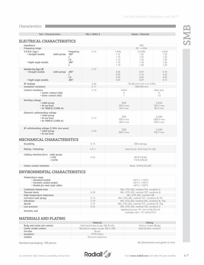
ELECTRICAL CHARACTERISTICS Impedance 50ΩFrequency range DC - 4 GHzV.S.W.R. (typ.)
• Straight models
• Right angle models
cable group:Frequency .085"22.6.085"2
3-14 1 GHz1.121.101.121.101.10
2.5 GHz1.221.221.221.181.20
4 GHz1.331.331.351.261.25
Insertion loss (typ.) dB• Straight models
• Right angle models
cable group: .085"22.6.085"
3-270.050.050.050.05
0.070.100.050.07
0.150.250.050.12
RF leakage 3-26 -55 dB min from 2 to 3 GHzInsulation resistance 3-11 1000 MΩ minContact resistance
• Center contact (mΩ)• Outer contact (mΩ)
3-16 Initial61
After test 8
1.5
Working voltage • Cable group• At sea level • At 70000 ft (21000 m)
2/50 250 V rms 60 V rms
2.6/50 335 V rms 85 V rms
Dielectric withstanding voltage • Cable group• At sea level • At 70000 ft (21000 m)
3-17 2/50 750 V rms 185 V rms
2.6/50 1000 V rms 250 V rms
RF withstanding voltage (5 MHz sine wave) • Cable group• At sea level
3-23 2/50 500 V rms
2.6/50 700 V rms
MECHANICAL CHARACTERISTICSDurability 3-15 500 matings
Mating / Unmating 3-5-1 Axial force: 62 N max (14 Lbf)
Cabling retention force cable group: • 2/50 • 2.6/50
3-24 58 N (13Lbf)110 N (25Lbf)
Center contact retention Axial: 10 N (2.25 Lbf)
ENVIRONMENTAL CHARACTERISTICSTemperature range
• Standard models• Hermetic sealed models• Models for semi-rigid cables
-65°C / + 165°C-65°C / +165°C-65°C / +105°C
Combined climate tests MIL-STD-202, method 102, condition CThermal shock 3-20 MIL-STD-202, method 107, condition BHigh temperature endurance MIL-STD-202, method 108Corrosion (salt spray) 3-13 MIL-STD-202, method 101, condition B, 5%Vibrations 3-18 MIL-STD-202, method 204, condition B, 15gShocks 3-19 MIL-STD-202, method 213, condition B, 75gLow pressure 3-22 MIL-STD-202, method 105, condition C
Hermetic sealApplied vacuum 10-6 mm of Hg (Torrs)
Leakage rate < 10-6 atm/cm3/s
MATERIALS AND PLATING Material Plating
Body and center pin contact Half hard brass as per QQ-B-626 Gold or nickel (Body)Center socket contact Beryllium copper as per QQ-C-530 Gold (Center contact)Ferrules BrassInsulators PTFE teflonGaskets Silicone elastomer
All dimensions are given in mm.
Test / Characteristics MIL-C-39012 A Values / Remarks
Standard packaging: 100 pieces
Characteristics
SMB

6-8
Our Most Important Connection is with You.™
Go online for data sheets & assembly instructions. Visit www.radiall.com and enter the part number.
Cable group Cable group dia. Part number Fig. Dimensions A (mm)
Captive centercontact Finish Note
RG178 / RG196 2/50/S R114 073 0001
yes
GoldRG174 / RG316 / RG179 2.6/50+75/S
R114 075 000R114 082 000
219.8
Full crimpRD316 2.6/50/D R114 083 000 18.4
RG178 / RG196 2/50S2002-1571-002
3
2002-7571-002 Nickel
RD178 2/50D2002-1571-005 Gold2002-7571-005 Nickel
RG174 / RG316 2.6/50S2002-1571-003 Gold2002-7571-003 Nickel
RD316 2.6/50D2002-1571-019 Gold2002-7571-019 Nickel
POWER RATING
STRAIGHT PLUGS CRIMP TYPE FOR FLEXIBLE CABLES
Fig. 1 Fig. 2
Characteristics
Plugs
SMB
Fig. 3

6-9
Our Most Important Connection is with You.™
Go online for data sheets & assembly instructions. Visit www.radiall.com and enter the part number.
STRAIGHT PLUGS CLAMP TYPE FOR FLEXIBLE CABLES
Cable group Cable group dia.
Part number (Gold)
Part number (Nickel) Fig. Captive center
contact
RG178 / RG196 2/50/S R114 003 000n/a 1
yes
RG174 / RG316 / RG179 2.6/50+75/S R114 005 000RG178 / RG196 2/50S 2002-1551-002 2002-7551-002
2RD178 2/50D 2002-1551-005
RG174 / RG316 2.6/50S 2002-7551-003 2002-7551-003RD316 2.6/50D 2002-7551-019 2002-7551-019
Fig. 1 Fig. 2
STRAIGHT PLUG FOR SEMI RIGID CABLES
Cable group
Cable group dia.
Part number(Gold)
Part number(Nickel) Fig.
Captive center
contactNote
RG405 .085"R114 053 000 1 no Solder type
2002-1541-010 2002-7541-0102 yes Solder clamp
RG402 .141" 2002-1541-003 2002-7541-009
Fig. 1 Fig. 2
Plugs and jacks
SMB

6-10
Our Most Important Connection is with You.™
Go online for data sheets & assembly instructions. Visit www.radiall.com and enter the part number.
RIGHT ANGLE PLUGS AND JACKS CRIMP TYPE FOR FLEXIBLE CABLES
Fig. 1
Cable group Cable group dia.
Part number (Gold)
Part number (Nickel) Fig.
Dimensions mm Captive centercontact Note
A BRG178 / RG196 2/50/S R114 183 000
n/a
1 13.7 15.3
yes
RG174 / RG316 / RG179 2.6/50+75/S
R114 185 000 2 Short versionR114 186 000
113.7 15.3
R114 186 100R114 187 000 15.1
15.4Full crimp
RD316 2.6/50/D R114 182 000 13.7
RG178 / RG196 2/50S2105-1521-002 2105-7521-002 3 13.2
16
2141-1521-002 4 12.7RD178 2/50D 2105-1521-005 2105-7521-005
3 13.2RG174 / RG316 / RG179 2.6/50S
2105-1521-003 2105-7521-0032141-1521-003 2141-7521-003 4 12.7
RD316 2.6/50D2105-1521-019 2105-7521-019 3 13.22141-1521-019 2141-7521-019 4 12.7
Fig. 2 Fig. 3 Fig. 4
Plugs and jacks
SMB

6-11
Our Most Important Connection is with You.™
Go online for data sheets & assembly instructions. Visit www.radiall.com and enter the part number.
RIGHT ANGLE PLUGS AND JACKS CLAMP TYPE FOR FLEXIBLE CABLES
Fig. 1
Cable group Cable group dia.
Part number (Gold)
Part number(Nickel) Fig.
Dimensions mm Captive centercontactA B
RG178 / RG1962/50/S R114 163 000
n/a 119
13.7
yes
2.2/50/D R114 163 420 16.7RG174 / RG316 / RG179 2.6/50+75/S R114 165 000 19
RG178 / RG197 2/50S2005-1551-002 2005-7551-002 22041-1551-002 3
RG174 / RG316 / RG179 2.6/50S2005-1551-003 2005-7551-003 22041-1551-003 2041-7551-003 3
RD316 2.6/50D 2005-1551-019 2
Fig. 2 Fig. 3
RIGHT ANGLE PLUGS AND JACKS FOR SEMI RIGID CABLES
Fig. 1 Fig. 2 Fig. 3
Cable group Cable group dia. Part number (Gold)
Part number (Nickel) Fig. Captive center
contact Note
RG405 .085"R114 169 000 n/a 1
yes
Cable bending required Solder type for semi rigid cable
2005-1541-010 2005-7541-010 2
Solder clamp2041-1541-010 2041-7541-010 3
RG402 .141"2005-1541-009 2005-7541-009 22041-1541-009 3
Plugs and jacks
SMB

6-12
Our Most Important Connection is with You.™
Go online for data sheets & assembly instructions. Visit www.radiall.com and enter the part number.
STRAIGHT JACKS CRIMP TYPE FOR FLEXIBLE CABLES
Cable group Cable group dia. Part number (Gold)
Part number (Nickel) Fig. Captive center
contact Note
RG174 / RG316 / RG179 2.6/50+75/S R114 238 000 1
yes
Full crimpRG178 / RG197 2/50S 2001-1571-002 2001-7571-002
2 Crimp typeRD178 2/50D 2001-1571-005
RG174 / RG316 / RG179 2.6/50S 2001-1571-003 2001-7571-003RD316 2.6/50D 2001-1571-019 2001-7571-019
Fig. 1 Fig. 2
Cable group Cable group dia.
Part number (Gold)
Part number (Nickel) Fig. Captive center
contactPanel
drilling Note
RG174 / RG316 / RG179 2.6/50+75/S R114 313 000 n/a 1
yes P08 Rear mount / Fill crimpRG178 / RG197 2/50S 2003-1571-002 2003-7571-002
2RD178 2/50D 2003-1571-005 2003-7571-005
RG174 / RG316 / RG179 2.6/50S 2003-1571-003 2003-7571-003
RD316 2.6/50D 2003-1571-019 2003-7571-019
STRAIGHT BULKHEAD JACKS CRIMP TYPE FOR FLEXIBLE CABLES
Fig. 1 Fig. 2
Jacks and bulkhead jacks
SMB

6-13
Our Most Important Connection is with You.™
Go online for data sheets & assembly instructions. Visit www.radiall.com and enter the part number.
STRAIGHT BULKHEAD JACKS CLAMP TYPE FOR FLEXIBLE CABLES
Cable group Cable group dia. Part number (Gold)
Part number (Nickel) Fig. Dimensions
A (mm)Captive center
contactPanel
drilling Note
RG178 / RG196 2/50/SR114 303 000
n/a 1
25.3
yes P08 Rear mount
R114 303 133 20.1
RG174 / RG316 / RG179 2.6/50+75/S R114 305 000 25.3
RG178 / RG197 2/50/S 2003-1551-002 2003-7551-002
2RD178 2/50/D 2003-1551-005
RG174 / RG316 / RG179 2.6/50/S 2003-1551-003 2003-7551-003
RD316 2.6/50/D 2003-1551-019
Fig. 1 Fig. 2
Bulkhead jacks
Cable group Cable group dia. Part number (Gold)
Part number (Nickel) Fig. Captive center contact Panel drilling Note
RG405 .085"R114 222 000 1
yes P082003-1541-010 2003-7541-0102 Solder
clamp typeRG402 .141" 2003-1541-009
STRAIGHT BULKHEAD JACK SOLDER TYPE FOR SEMI-RIGID CABLE
Fig. 1 Fig. 2
RIGHT ANGLE BULKHEAD CRIMP TYPE FOR FLEXIBLE CABLES
Cable group Cable group dia.
Part number (Gold)
Part number (Nickel)
Captive centercontact
Panel drilling
RG178 / RG197 2/50S 2106-1521-002 2106-7521-002
yes P08RD178 2/50D 2106-1521-005
RG174 / RG316 / RG179 2.6/50/S 2106-1521-003 2106-7521-003
RD316 2.6/50/D 2106-1521-019 2106-7521-019
SMB

6-14
Our Most Important Connection is with You.™
Go online for data sheets & assembly instructions. Visit www.radiall.com and enter the part number.
Part number (Gold)
Part number (Nickel) Fig. Dimensions mm Captive center
contact Panel drilling NoteA B
R114 413 000n/a
1no
P01 Square flange / Extended dielectricR114 450 000 2 P06 2 hole glange / Extended dielectric / Unit packaging
2484-1511-0003
9.5 5.9yes 2.36mm hole dia.
2486-1511-000 2486-7511-000 12.7 8.6
STRAIGHT FLANGE RECEPTACLES (male center contact)
Fig. 1
Fig. 2
Fig. 3
Part number (Gold)
Part number (Nickel) Fig.
Dimensions mm Captive center contact Panel drilling Note
A B C D
R114 553 000n/a
115.7
6.71 1.5
yes P08
Front mountR114 554 000 2 10.9 Rear mountR114 603 000 3 Hermetically sealed
2004-1511-000 2004-7511-000 2 15.5 10.8 0.9 1.6 Rear mount / Solder pot contact
2014-1511-000 2014-7511-000 4 Recessed front mount / Solder pot contact
2019-1511-000 2019-7511-000 1 15.5 5.9 0.9 1.6 Front mount / Solder pot contact
STRAIGHT BULKHEAD RECEPTACLES (male center contact)
Fig. 1
Fig. 4
Fig. 2
Fig. 3
ReceptaclesSM
B

6-15
Our Most Important Connection is with You.™
Go online for data sheets & assembly instructions. Visit www.radiall.com and enter the part number.
Part number (Gold)
Part number (Nickel) Fig. Captive center
contactAssembly
instructionsPanel
drilling Note
R114 416 020
n/a
1
yes
P02 Press fit pins
R114 423 000 5
M01
SMT edge card
R114 424 0002
SMT
R114 424 100 SMT / Tape & Reel 100 pieces
R114 425 000 4 P05 Female plug
R114 426 000
3
P03
2009-1511-000 2009-7511-000
P04
No standoff
2009-1511-050 2009-7511-050 Standoff legs
2025-1511-000 2025-7511-000 7No standoff
2109-1511-000 2109-7511-000 6
Fig. 6 Fig. 7
SMBReceptacles
Part number Captive center contact Panel drilling Finish
R114 504 225 yes P10 Nickel
STRAIGHT PRESS IN RECEPTACLE (male)
Fig. 1 Fig. 2 Fig. 3 Fig. 4
STRAIGHT PCB RECEPTACLES (male and female)
Fig. 5
RIGHT ANGLE BULKHEAD RECEPTACLES (male center contact)
Part number Captive center contact
Panel drilling Finish Note
R114 670 000yes P08
Gold Solder pot contact2012-1511-000
2012-7511-000 Nickel

6-16
Our Most Important Connection is with You.™
Go online for data sheets & assembly instructions. Visit www.radiall.com and enter the part number.
Receptacles
SMB
Fig. 1Fig. 4Fig. 2 Fig. 3
Part number (Gold)
Part number (Nickel) Fig.
Dimensions mm Captive centercontact
Assembly instructions
Panel drilling Note
A B C DR114 664 000
n/a
1
yes
M01Packaging 100p reel
R114 664 120 SMT / Packaging 500p reelR114 665 000
2 12.6 4P03
R114 665 020R114 673 020 3 Packaging unit
Rear mountR114 673 120 4R114 670 000 5 P08 Packaging 100 piecesR114 673 823 6 P09 Packaging 200 pieces
2010-1511-000 2010-7511-0007
10.9 3.83.9
12.7P04
2010-1511-002 2010-7511-002 12.7 5.5 14.2
RIGHT ANGLE PCB RECEPTACLES (male center contact)
Fig. 6Fig. 5Fig. 7

6-17
Our Most Important Connection is with You.™
Go online for data sheets & assembly instructions. Visit www.radiall.com and enter the part number.
Fig. 1 Fig. 2
Fig. 5
Fig. 3
IN SERIES ADAPTERS
Part number (Gold)
Part number (Nickel) Fig.
Dimensions Captive center contact Panel drilling Note
A B
R114 703 000
n/a
119
yes
male - maleR114 704 000 2 female - femaleR114 720 000 3 11
P08bulkhead male - male
R114 753 000 4 hermetically sealed male - maleR114 780 000 5
1914
tee female / male - maleR114 781 000
6 tee male / male - male5207-1501-000 5207-7501-000 12.75222-1501-000 5222-7501-000 3
17.510.7 bulkhead male - male
5213-1501-000 5213-7501-000 1 male - male5215-1501-000 5215-7501-000 5 19 12.9 tee female / male - male5216-1501-000 5216-7501-000 2 17.5 female - female5208-1501-000 5208-7501-000 7 tee female / female - female
Fig. 6
Fig. 4
Fig. 7
SMBAdapters

6-18
Our Most Important Connection is with You.™
Go online for data sheets & assembly instructions. Visit www.radiall.com and enter the part number.
Radiall introduces new SMB LOCK plugs with a 2-step connection system:1 Snap the plug on the male connector (fig. 1)2 Lock the couple by pushing down the coupling nut (fig. 2)
This new range• Is intermateable with the standard SMB male connectors• Benefits from a low intermodulation
• Replaces the standard SMB and screw-on connectors in all applications requiring: • A fast connection • A reliable lock-on connection • Long durability
• Possibility to visually control the locking system
SMB
LOCK
Introduction
• The connector allows a 360° cable rotation• Coupling nut The coupling nut is made with POM (halogen free). Its standard color is black.
Letter mm inch
min. max. min. max. A DIA 2.06 .081
F 3.58 .141G 3.58 .141H 1.63 .064I 0.18 .007J 0.18 0.94 .007 .037K 2.97 .117
PLUG (with female contact)
Interface

6-19
Our Most Important Connection is with You.™
Go online for data sheets & assembly instructions. Visit www.radiall.com and enter the part number.
SMB
LOCK
ELECTRICAL CHARACTERISTICS Impedance 50Ω
Operating frequency DC to 4 GHz
Tyical V.S.W.R.• Straight models
• Right angle models
.085" 2.6/50 .085" 2.6/50
2 GHz1.151.201.051.15
4 GHz1.201.251.151.25
RF Insertion loss• Straight models
• Right angle models
.085" 2.6/50 .085" 2.6/50
0.20√F (GHz)0.25√F (GHz)0.25√F (GHz)0.50√F (GHz)
Testing voltage (V RMS) .085" 2.6/50
7501000
Working voltage (V RMS) .085" 2.6/50
335335
Insulation resistance (MΩ) 1000
MECHANICAL CHARACTERISTICSLife 500 matings min
Cable retention force.085" 2.6/50 5/50/S
220 N 110 N 110 N
Coupling nut retention force 50 N min
Vibrations MIL STD 202 F method 240D, condition B
ENVIRONMENTAL CHARACTERISTICSTemperature range -35°C / + 125°C
MATERIALS AND PLATING Material Plating
Bodies Brass BBR
Center contact Beryllium copper Gold
Outer contact Bronze
Insulator PTFE
Coupling nut POM (halogen free)
Standard packaging: 100 pieces (For unit packaging, add "W" after the P/N).
Test / Characteristics Values / Remarks
Characteristics

6-20
Our Most Important Connection is with You.™
Go online for data sheets & assembly instructions. Visit www.radiall.com and enter the part number.
SMB
LOCK
Cable group Cable group dia Part number Dimensions A (mm) Captive center contact
RG174 / RG188 / RG316 2.6/50/S R117 082 807 3.25 yes
STRAIGHT PLUG FULL CRIMP TYPE FOR FLEXIBLE CABLES
RIGHT ANGLE PLUG CRIMP TYPE FOR FLEXIBLE CABLES
Cable group Cable group dia Part number Dimensions A (mm) Captive center contact
RG174 / RG188 / RG316 2.6/50/S R117 186 807 3.25 yes
Plugs
BULKHEAD PLUG RECEPTACLE (rear fixing)
Part number Panel drilling Finish
R115 556 000 P08 Gold
• Lower mating/unmating force (from 2.5 N to 6N)• Receptacles intermateable with SMB connectors• Gold finishThe SMB limited detent connectors have the same electrical characteristics as standard SMB connectors
Receptacles

6-21
Our Most Important Connection is with You.™
Go online for data sheets & assembly instructions. Visit www.radiall.com and enter the part number.
STRAIGHT PCB RECEPTACLES (female center contact)
Part number Captive center contact Panel drilling Finish Packaging
R115 427 000 yes P05 Gold Unit
SMB-
A an
d SU
BGLI
S
Part number Captive center contact Panel drilling Finish Packaging
R115 666 000 yes P04 Gold Unit
RIGHT ANGLE PCB RECEPTACLE (female center contact)
SMB limited detent (SMB-A)
PCB RECEPTACLES
Part number Captive center contact Panel drilling Finish Packaging Note
R116 426 000 yes P03 Gold Unit Male center contact
Slide on connectors (mating/unmating force: 2.2 N to 4.9 N)The SMB slide-on connectors are completely intermateable with standard SMB and SMB limited detent connectors and in this regard, they can be used for test applications. The SMB slide-on connectors have the same electrical characteristics as standard SMB connectors.
SMB slide-on (SUBGLIS)

6-22
Our Most Important Connection is with You.™
Go online for data sheets & assembly instructions. Visit www.radiall.com and enter the part number.
SMB Panel drilling
mm Maxi mini A 4.02 3.98
A
PO1 PO5
PO9
PO2
PO6 P10
PO4
PO8
PO3
PO7
M01Video shadow:
Vaccum nozzle dimensions:
Part number
R114 423 000
Part number
R113 423 000
Part number
R114 424 000
Part number
R114 424 000R114 424 100
Part number
R114 664 000R114 664 120
Part number
R114 424 000 R114 424 100R114 664 000 R114 664 120
Assembly instructions

6-23
Our Most Important Connection is with You.™
Go online for data sheets & assembly instructions. Visit www.radiall.com and enter the part number.
SMC
GENERAL• Subminiature coaxial connectors• Screw-on coupling• Plugs have female contacts• Jacks have male contacts• Low weight• Reduced outline dimensions
APPLICABLE STANDARDS• MIL-C-39012
APPLICATIONS• Civil and military telecommunications• Aeronautics• Missiles• Edge mounting applications
50Ω DC - 10 GHz
Letter mm inch
min. max. min. max. A 5.14 5.55 .202 .219B 3.20 4.20 .126 .165C 0.25 0.35 .010 .014D 2.95 3.00 .116 .118E 2.80 3.20 .110 .126F 2.80 3.40 .110 .134G 3.15 3.40 .124 .134H 2.00 2.05 .079 .081I 3.75 3.80 .148 .150
Letter mm inch
min. max. min. max. A 6.00 6.20 .236 .244B 3.15 3.35 .124 .132C 0.05 0.20 .002 .008D 0.65 1.50 .026 .059E 1.30 2.05 .051 .081F 3.40 3.71 .134 .146G 3.40 3.95 .134 .156H 3.65 3.69 .144 .145I 2.08 2.13 .082 .084J 0.48 0.52 .019 .020K -- 0.20 -- .008
PLUG JACK
Introduction
Interface

6-24
Our Most Important Connection is with You.™
Go online for data sheets & assembly instructions. Visit www.radiall.com and enter the part number.
SMC
ELECTRICAL CHARACTERISTICS Impedance 50ΩFrequency range DC - 10 GHzV.S.W.R. (typ.)
• Straight• Right angle
cable 3-14 2/501.25 + 0.04 F (GHz)1.40 + 0.06 F (GHz)
2.6/501.20 + 0.04 F (GHz)1.30 + 0.04 F (GHz)
Insertion loss• Straight• Right angle
3-270.25 dB max. at 4 GHz0.5 dB max. at 4 GHz
RF leakage 3-26 -60 dB min between 2 and 3 GHzInsulation resistance 3-11 1000 MΩ minContact resistance
• Center contact (mΩ) • Outer contact (mΩ)
3-16 Initial61
After environment 8
1.5
Voltage rating (volts RMS) • At sea level • At 70000 ft (21000 m)
cable 2/50 250 V rms60 V rms
2.6/50 335 V rms 85 V rms
Dielectric withstanding voltage • At sea level • At 70000 ft (21000 m)
cable 3-17 2/50 750 V rms 185 V rms
2.6/50 1000 V rms 250 V rms
RF high potential withstanding voltage (Frequency 5 MHz)
• At sea levelcable 3-23 2/50
500 V rms 2.6/50
700 V rms
MECHANICAL CHARACTERISTICSDurability 3-15 500 matingsForce to engage and disengage 3-5-1 torque: 16 inch-ounces max - 11.3 Ncm
Mating torque 35 to 50 inch-ounces - 25 to 35 Ncm
Coupling nut proof torque 100 inch-ounces - 71 Ncm
Coupling nut retention force 3-25 35 Ibs min - 156 N min
Cabling retention force cable 3-24 2/5013 Ibs - 58 N
2.6/50 25 Ibs - 110 N
Contact captivation Axial force: 4 Ibs - 18 N torque: not applicable
ENVIRONMENTAL CHARACTERISTICSOperating temperature range
• Standard models and hermetic• Models for semi-rigid cables
-65°C / + 165°C-65°C / +105°C
Temperature cycling MIL-STD-202, method 102, condition CThermal shock 3-20 MIL-STD-202, method 107, condition BHigh temperature test MIL-STD-202, method 108Corrosion (salt spray) 3-13 MIL-STD-202, method 101, condition B, 5%Vibration 3-18 MIL-STD-202, method 204, condition D, 20gShock 3-19 MIL-STD-202, method 213, condition C, 100gMoisture resistance 3-21 not applicableBarometric pressure 3-22 MIL-STD-202, method 105, condition C
Hermetic testDown to 10-6 mm Hg (Torr)
Leak rate <1 x 10⁻⁶ atm/cm3/sec
MATERIALS AND PLATING Material Plating
Bodies and male contacts Brass, half hard per QQ-B-626 Gold to satisfy the corrosion requirements (bodies)
Female contacts and interfaces Beryllium copper per QQ-C-530 Gold (Center contact)Ferrules BrassInsulators PTFE teflonGaskets Silicone rubber
All dimensions are given in mm.
Test / Characteristics MIL-C-39012 paragraph Values / Remarks
Characteristics

6-25
Our Most Important Connection is with You.™
Go online for data sheets & assembly instructions. Visit www.radiall.com and enter the part number.
Fig. 2
SMC
STRAIGHT PLUGS
Cable group Cable group dia Part number (Gold)
Part number (Nickel) Fig. Note
RG178 / RG196 2/50/S R112 003 000
n/a1 Clamp type
RG174 / RG316 / RG179 2.6/50+75/SR112 005 000R112 075 000 2 Crimp type
RG405 .085" R112 053 000 3 Solder type
RG178 / RG196 2/50/S1002-1571-002 1002-7571-002 5 Crimp type1002-1551-002 1002-7551-002
4 Clamp typeRD178 2/50/D
1002-1551-005 1002-7551-0051002-1571-005 1002-7571-005 5 Crimp type
RG174 / RG316 / RG179 2.6/50/S1002-1551-003 1002-7551-003 4 Clamp type1002-1571-003 1002-7571-003 5 Crimp type
RD316 2.6/50/D1002-1551-019 1002-7551-019 4 Clamp type1002-1571-019 1002-7571-019 5 Crimp type
RG405 .085" 1002-1541-010 1002-7541-0104 Solder clamp
RG402 .141" 1002-1541-009 1002-7541-009
Fig. 1 Fig. 3
RIGHT ANGLE PLUGS
Cable group Cable group dia Part number (Gold)
Part number (Nickel) Fig.
Dimensions mmNote
A dia B dia
RG174 / RG316 / RG179 2.6/50+75/S R112 165 000
n/a
1 19 15.9
Crimp typeRG178 / RG196 2/50 R112 183 0002
16 15.5
RG174 / RG316 / RG179 2.6/50+75/S R112 186 000 15.3 15.9
RG178 / RG196 2/50/S1005-1551-002 1005-7551-002 1 14.9
13.9
Clamp type
1105-1521-002 1105-7521-002 2 16 Crimp type
RD178 2/50/D1005-1551-005 1005-7551-005 1 14.9 Clamp type
1105-1521-005 1105-7521-005 2 16 Crimp type
RG174 / RG316 / RG179 2.6/50/S1005-1551-003 1005-7551-003 1 14.9 Clamp type
1105-1521-003 1105-7521-003 2 16 Crimp type
RD316 2.6/50/D1005-1551-019 1005-7551-019 1 14.9 Clamp type
1105-1521-019 1105-7521-019 2 16 Crimp type
RG405 .085" 1005-1541-010 1005-7541-0101 14.9 Solder clamp
RG402 .141" 1005-1541-009 1005-7541-009
Fig. 1
Plugs and jack
Fig. 5Fig. 4
Fig. 2

6-26
Our Most Important Connection is with You.™
Go online for data sheets & assembly instructions. Visit www.radiall.com and enter the part number.
Fig. 4
STRAIGHT JACK
Cable group Cable group dia Part number (Gold)
Part number (Nickel) Note
RG174 / RG316 / RG179 2.6/50+75/S R112 205 000Clamp type
RG178 / RG196 2/50/S1001-1551-002 1001-7551-0021001-1571-002 1001-7571-002 Crimp type
RD178 2/50/D1001-1551-005 1001-7551-005 Clamp type1001-1571-005 1001-7571-005 Crimp type
RG174 / RG316 / RG179 2.6/50/S1001-1551-003 1001-7551-003 Clamp type1001-1571-003 1001-7571-003 Crimp type
RD316 2.6/50/D1001-1551-019 1001-7551-019 Clamp type1001-1571-019 1001-7571-019 Crimp type
RG405 .085" 1001-1571-010 1001-7571-010Solder clamp
RG402 .141" 1001-1571-009 1001-7571-009
SMC
BULKHEAD STRAIGHT AND RIGHT ANGLE JACKS
Cable group Cable group dia Part number (Gold)
Part number (Nickel) Fig. Panel
drilling Note
RG178 / RG196 2/50/S R112 303 0001
P03
RG174 / RG316 / RG179 2.6/50+75/S R112 305 000
RG178 / RG196 2/50/S
1003-1551-002 1003-7551-002 2 Clamp type1003-1571-002 1003-7571-002 3 Crimp type1006-1551-002 1006-7551-002
4Clamp type
1106-1521-002 1106-7521-002 Crimp type
RD178 2/50/D
1003-1551-005 1003-7551-005 2 Clamp type1003-1571-005 1003-7571-005 3 Crimp type1006-1551-005 1006-7551-005
4Clamp type
1106-1521-005 1106-7521-005 Crimp type
RG174 / RG316 / RG179 2.6/50/S
1003-1551-003 1003-7551-003 2 Clamp type1003-1571-003 1003-7571-003 3 Crimp type1006-1551-003 1006-7551-003
4Clamp type
1106-1521-003 1106-7521-003 Crimp type
Jacks and receptacles
Fig. 1 Fig. 2
Fig. 3
Fig. 1 Fig. 2 Fig. 3

6-27
Our Most Important Connection is with You.™
Go online for data sheets & assembly instructions. Visit www.radiall.com and enter the part number.
SMC
Part number (Gold)
Part number (Nickel) Fig.
Dimensions (mm)Panel drilling
A B C
R112 403 000 n/a 1 P011484-1511-000 1484-7511-000
29.5 5.9 2.4
1486-1511-000 1486-7511-00012.7 8.6 2.6
1490-1511-000 1490-7511-0003
1488-1511-000 1488-7511-000 9.5 5.9 2.4
SQUARE FLANGE RECEPTACLES
BULKHEAD RECEPTACLES WITH SOLDER POT CONTACT
Part number (Gold)
Part number (Nickel) Fig.
Dimensions (mm)Panel drilling Note
A B
R112 553 000n/a
1
P03
Front mountR112 554 000 2 Rear mountR112 670 000 3 0.6 1.55 Front mount
1004-1511-000 1004-7511-000 2 Rear mount1019-1511-000 1019-7511-000 1
Front mount1012-1511-000 1012-7511-000 3 0.9 2.41017 1511-000 1017 7511-000 4
Fig. 1Fig. 3
Fig. 2
Jacks and receptacles
BULKHEAD STRAIGHT AND RIGHT ANGLE JACKS (CONTINUED)
Cable group Cable group dia Part number (Gold)
Part number (Nickel) Fig. Panel
drilling Note
RD316 2.6/50/D
1003-1551-019 1003-7551-019 2
P03
Clamp type1003-1571-019 1003-7571-019 3 Crimp type1006-1551-019 1006-7551-019
4Clamp type
1106-1521-019 1106-7521-019 Crimp type
RG405 .085"1003-1541-010 1003-7541-010 2
Solder clamp1006-1541-010 1006-7541-010 4
RG402 .141"1003-1541-009 1003-7541-009 21006-1541-009 1006-7541-009 4
Fig. 1 Fig. 2 Fig. 3
Fig. 4

6-28
Our Most Important Connection is with You.™
Go online for data sheets & assembly instructions. Visit www.radiall.com and enter the part number.
PCB RECEPTACLES
Part number (Gold)
Part number (Nickel) Fig.
Dimensions (mm)Panel drilling Note
A B C
R112 426 000n/a
1 11.8 4.4P02 Standoff legs
R112 665 000 2 14.2
4
12.71009-1511-000 1009-7511-000 1 11.4
P04 No standoff1010-1511-000 1010-7511-0002 14
71010-1511-001 1010-7511-001 8.81109-1511-000 1109-7511-000 1 16.3
P04 + P03 No standoff, bulkhead type1110-1511-000 1110-7511-000 2 18 71009-1511-005 1009-7511-005 3 P04 End launch type
Fig. 1 Fig. 2
IN SERIES ADAPTERS
Part number (Gold) Fig. Dimensions
A (mm)Panel
drilling Note
R112 720 000 1 19 P03 male - male bulkheadR112 780 000 2 tee male - male / female
5822-1501-000 1 17.5 P03 female - femaleFig. 1
Fig. 2
Receptacles and adapters
PO1 PO2 PO3
mm Maxi mini A 4.9 4.8 B 2.3 2.2 C 6.95 7.05
B DIA 4 holes
A DIA C
mm Maxi mini A 5 4.9 B 4.6 4.45
A B
mm Maxi mini A 2.59 2.49 B 1.4 1.3 C 5.00 5.16
B DIA 5 holes
A C
Panel drilling
SMC
Fig. 3
PO4