asphalt surfaced airfields - federal … or fatigue cracking is a series of interconnecting cracks...
TRANSCRIPT
ASPHALT SURFACED AIRFIELDS
PAVER™ DISTRESS IDENTIFICATION MANUAL
DEVELOPED BY:
US ARMY CORPS OF ENGINEERS ERDC-CERL
SPONSORED BY:
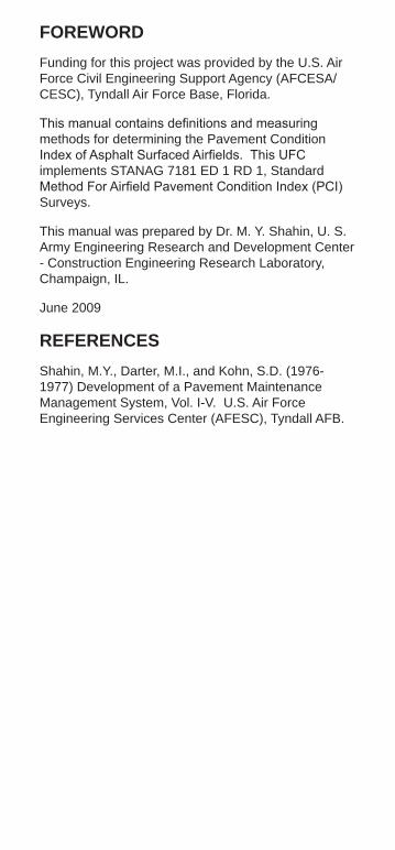
FOREWORD Funding for this project was provided by the U.S. Air Force Civil Engineering Support Agency (AFCESA/ CESC), Tyndall Air Force Base, Florida.
This manual contains definitions and measuring methods for determining the Pavement Condition Index of Asphalt Surfaced Airfields. This UFC implements STANAG 7181 ED 1 RD 1, Standard Method For Airfield Pavement Condition Index (PCI) Surveys.
This manual was prepared by Dr. M. Y. Shahin, U. S. Army Engineering Research and Development Center - Construction Engineering Research Laboratory, Champaign, IL.
June 2009
REFERENCES Shahin, M.Y., Darter, M.I., and Kohn, S.D. (19761977) Development of a Pavement Maintenance Management System, Vol. I-V. U.S. Air Force Engineering Services Center (AFESC), Tyndall AFB.
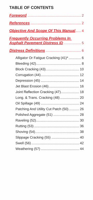
TABLE OF CONTENTS
Foreword ........................................................ 2
References ..................................................... 2
Objective And Scope Of This Manual ...... 4
Frequently Occurring Problems In Asphalt Pavement Distress ID .................. 5
Distress Definitions ..................................... 6
Alligator Or Fatigue Cracking (41)* ............. 6
Bleeding (42) ............................................... 8
Block Cracking (43) ................................... 10
Corrugation (44) ........................................ 12
Depression (45) ........................................ 14
Jet Blast Erosion (46) ................................ 16
Joint Reflection Cracking (47) ................... 18
Long. & Trans. Cracking (48) .................... 20
Oil Spillage (49) ........................................ 24
Patching And Utility Cut Patch (50) ........... 26
Polished Aggregate (51) ........................... 28
Raveling (52) ............................................. 30
Rutting (53) ............................................... 36
Shoving (54) .............................................. 38
Slippage Cracking (55) ............................. 40
Swell (56) .................................................. 42
Weathering (57) ........................................ 44

OBJECTIVE AND SCOPE OF THIS MANUAL This manual contains distress definitions and measurement methods for asphalt surfaced airfields. This information is used to determine the Pavement Condition Index (PCI).
4
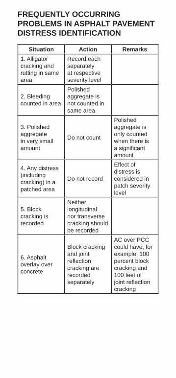
FREQUENTLY OCCURRING PROBLEMS IN ASPHALT PAVEMENT DISTRESS IDENTIFICATION
Situation Action Remarks 1. Alligatorcracking and rutting in same area
Record each separately at respective severity level
2. Bleedingcounted in area
Polished aggregate is not counted in same area
3. Polishedaggregate in very small amount
Do not count
Polished aggregate is only counted when there is a significant amount
4. Any distress(including cracking) in a patched area
Do not record
Effect of distress is considered in patch severity level
5. Blockcracking is recorded
Neither longitudinal nor transverse cracking should be recorded
6. Asphaltoverlay over concrete
Block cracking and joint reflection cracking are recorded separately
AC over PCC could have, for example, 100 percent block cracking and 100 feet of joint reflection cracking

ALLIGATOR OR FATIGUE CRACKING (41)*
Description Alligator or fatigue cracking is a series of interconnecting cracks caused by fatigue failure of the asphalt surface under repeated traffic loading. The cracking initiates at the bottom of the asphalt surface (or stabilized base) where tensile stress and strain is highest under a wheel load. The cracks propagate to the surface initially as a series of parallel cracks. After repeated traffic loading, the cracks connect and form multi-sided, sharp-angled pieces that develop a pattern resembling chicken wire or the skin of an alligator. The pieces are less than 2 feet (0.6 meters) on the longest side. Alligator cracking occurs only in areas that are subjected to repeated traffic loadings, such as wheel paths. Therefore, it would not occur over an entire area unless the entire area was subjected to traffic loading. (Pattern-type cracking, which occurs over an entire area that is not subject to loading, is rated as block cracking, which is not a load associated distress.) Alligator cracking is considered a major structural distress.
Severity Levels
L Fine, longitudinal hairline cracks running parallel to each other with no or only a few interconnecting cracks. The cracks are not spalled.
M Further development of light alligator cracking into a pattern or network of cracks that may be lightly spalled. Medium severity alligator cracking is defined by a well-defined pattern of interconnecting cracks, where all pieces are securely held in place (good aggregate interlock between pieces).
H Network or pattern cracking progressed so that pieces are well-defined and spalled at the edges; some of the pieces rock under traffic and may cause FOD potential.
How To Measure Alligator cracking is measured in square feet (square meters) of surface area. The major difficulty in measuring this type of distress is that many times two or three levels of severity exist within one distressed area. If these portions can be easily distinguished from each other, they should be measured and recorded separately. However, if the different levels of severity cannot be easily divided, the entire area should be rated at the highest severity level present. If alligator cracking and rutting occur in the same area, each is recorded separately at its respective severity level.
*PAVER Distress Code
6

H I
G H
M
E D
I U
M
L O
W
41 A
LLIG
ATO
R
7
BLEEDING (42)
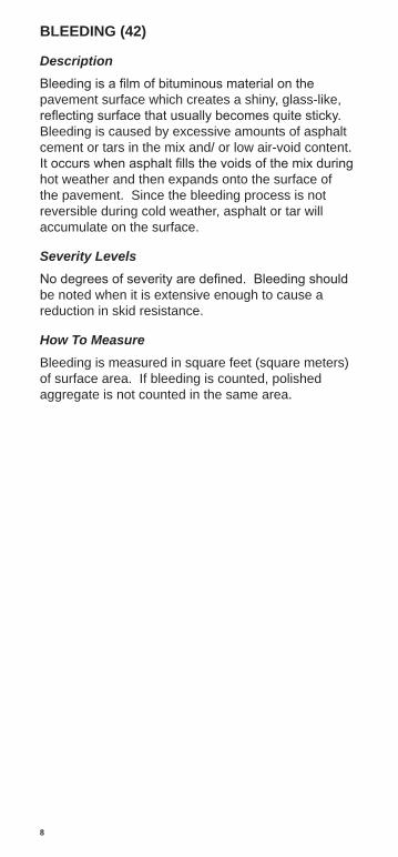
Description Bleeding is a film of bituminous material on the pavement surface which creates a shiny, glass-like, reflecting surface that usually becomes quite sticky. Bleeding is caused by excessive amounts of asphalt cement or tars in the mix and/ or low air-void content. It occurs when asphalt fills the voids of the mix during hot weather and then expands onto the surface of the pavement. Since the bleeding process is not reversible during cold weather, asphalt or tar will accumulate on the surface.
Severity Levels No degrees of severity are defined. Bleeding should be noted when it is extensive enough to cause a reduction in skid resistance.
How To Measure Bleeding is measured in square feet (square meters) of surface area. If bleeding is counted, polished aggregate is not counted in the same area.
8
42 B
LEE
DIN
G
9
BLOCK CRACKING (43)
Description Block cracks are interconnected cracks that divide the pavement into approximately rectangular pieces. The blocks may range in size from approximately 1 by 1 foot to 10 by 10 feet (0.3 by 0.3 meters to 3 by 3 meters). Block cracking is caused mainly by shrinkage of the asphalt concrete (AC) and daily temperature cycling (which results in daily stress/ strain cycling). It is not load associated. The occurrence of block cracking usually indicates that the asphalt has hardened significantly. Block cracking normally occurs over a large proportion of pavement area but sometimes will occur in non-traffic areas. This type of distress differs from alligator cracking in that alligator cracks form smaller, multi-sided pieces with sharp angles. Also, unlike block cracks, alligator cracks are caused by repeated traffic loadings and, therefore, are located only in traffic areas (i.e., wheel paths).
Severity Levels
L Blocks are defined by cracks that are non-spalled (sides of the crack are vertical) or only lightly spalled, causing no FOD potential. Non-filled cracks have 1/4 inch (6 mm) or less mean width, and filled cracks have filler in satisfactory condition.
M Blocks are defined by either: (1) Filled or non-filled cracks that are moderately spalled (some FOD potential); (2) Non-filled cracks that are not spalled or have only minor spalling (some FOD potential), but have a mean width greater than approximately 1/4 inch (6 mm); or (3) Filled cracks that are not spalled or have only minor spalling (some FOD potential), but have filler in unsatisfactory condition.
H Blocks are well-defined by cracks that are severely spalled, causing a definite FOD potential.
How To Measure Block cracking is measured in square feet (square meters) of surface area. It usually occurs at one severity level in a given pavement section; however, any areas of the pavement section having distinctly different levels of severity should be measured and recorded separately. For asphalt pavements, not including AC over PCC, if block cracking is recorded, no longitudinal and transverse cracking should be recorded in the same area. For asphalt overlay over concrete, block cracking, joint reflection cracking, and longitudinal and transverse cracking reflected from old concrete should all be recorded separately.
10

H I
G H
M
E D
I U
M
L O
W
43 B
LOC
K C
RA
CK
ING
11

CORRUGATION (44)
Description Corrugation is a series of closely spaced ridges and valleys (ripples) occurring at fairly regular intervals, usually less than 5 feet (1 1/2 meters) along the pavement. The ridges are perpendicular to the traffic direction. Traffic action combined with an unstable pavement surface or base usually causes this type of distress.
Severity Levels
L Corrugations are minor and do not significantly affect ride quality (see measurement criteria below).
M Corrugations are noticeable and significantly affect ride quality (see measurement criteria below).
H Corrugations are easily noticed and severely affect ride quality (see measurement criteria below).
How To Measure Corrugation is measured in square feet (square meters) of surface area. The mean elevation difference between the ridges and valleys of the corrugations indicates the level of severity. To determine the mean elevation difference, a 10 foot (3 meter) straightedge should be placed perpendicular to the corrugations so that the depth of the valleys can be measured in inches (mm). The mean depth is calculated from five such measurements.
Measurement Criteria
Severity Runways & High-Speed Taxiways
Taxiways & Aprons
L < 1/4 in. (< 6 mm)
< 1/2 in. (< 13 mm)
M 1/4 to 1/2 in. (6 to 13 mm)
1/2 to 1 in. (13 to 25 mm)
H > 1/2 in. (> 13 mm)
> 1 in. (> 25 mm)
12

DEPTH • A+B+C+D+E 5
13
44 C
OR
RU
GA
TIO
N
DEPRESSION (45) Description Depressions are localized pavement surface areas having elevations slightly lower than those of the surrounding pavement. In many instances, light depressions are not noticeable until after a rain, when ponding water creates “birdbath” areas; but the depressions can also be located without rain because of stains created by ponding water. Depressions can be caused by settlement of the foundation soil or can be “built up” during construction. Depressions cause roughness and, when filled with water of sufficient depth, can cause hydroplaning of aircraft.
Severity Levels L Depression can be observed or located by
stained areas, only slightly affects pavement riding quality, and may cause hydroplaning potential on runways (see measurement criteria below).
M The depression can be observed, moderately affects pavement riding quality, and causes hydroplaning potential on runways (see measurement criteria below).
H The depression can be readily observed, severely affects pavement riding quality, and causes definite hydroplaning potential (see measurement criteria below).
How To Measure Depressions are measured in square feet (square meters) of surface area. The maximum depth of the depression determines the level of severity. This depth can be measured by placing a 10 foot (3 meter) straightedge across the depressed area and measuring the maximum depth in inches (mm). Depressions larger than 10 feet (3 meters) across must be measured by either visual estimation or direct measurement when filled with water.
Maximum Depth of Depression
Severity Runways & High-Speed Taxiways
Taxiways & Aprons
L 1/8 to 1/2 in. (3 to 13 mm)
1/2 to 1 in. (13 to 25 mm)
M 1/2 to 1 in. (13 to 25 mm)
1 to 2 in. (25 to 51 mm)
H > 1 in. (> 25 mm)
> 2 in. (> 51 mm)
14

H I
G H
M
E D
I U
M
L O
W
45 D
EP
RE
SS
ION
15

JET BLAST EROSION (46)
Description Jet blast erosion causes darkened areas on the pavement surface when bituminous binder has been burned or carbonized; localized burned areas may vary in depth up to approximately 1/2 inch (13 mm).
Severity Levels No degrees of severity are defined. It is sufficient to indicate that jet blast erosion exists.
How To Measure Jet blast erosion is measured in square feet (square meters) of surface area.
16

46 J
ET
BLA
ST
17

JOINT REFLECTION CRACKING FROM PCC (47)
Description This distress occurs only on pavements having an asphalt or tar surface over a PCC slab. This category does not include reflection cracking from any other type of base (i.e., cement stabilized, lime stabilized); such cracks are listed as longitudinal and transverse cracks. Joint reflection cracking is caused mainly by movement of the PCC slab beneath the AC surface because of thermal and moisture changes; it is not load related. However, traffic loading may cause a breakdown of the AC near the crack, resulting in spalling and FOD potential. If the pavement is fragmented along a crack, the crack is said to be spalled. A knowledge of slab dimensions beneath the AC surface will help to identify these cracks.
Severity Levels
L Cracks have only light spalling (little or no FOD potential) or no spalling and can be filled or non-filled. If non-filled, the cracks have a mean width of 1/4 inch (6 mm) or less. Filled cracks are of any width, but their filler material is in satisfactory condition.
M One of the following conditions exists: (1) cracks are moderately spalled (some FOD potential) and can be either filled or non-filled of any width; (2) filled cracks are not spalled or are only lightly spalled, but the filler is in unsatisfactory condition; (3) non-filled cracks are not spalled or are only lightly spalled, but the mean crack width is greater than 1/4 inch (6 mm); or (4) light random cracking exists near the crack or at the corner of intersecting cracks.
H Cracks are severely spalled (definite FOD potential) and can be either filled or non-filled of any width.
How To Measure Joint reflection cracking is measured in linear feet (linear meters). The length and severity level of each crack should be identified and recorded. If the crack does not have the same severity level along its entire length, each portion should be recorded separately. For example, a crack that is 50 feet (15 meters) long may have 10 feet (3 meters) of high severity, 20 feet (6 meters) of medium severity, and 20 feet (6 meters) of low severity; these would all be recorded separately. If the different levels of severity in a portion of a crack cannot be easily divided, that portion should be rated at the highest severity present.
18

H I
G H
M
E D
I U
M
L O
W
47 J
OIN
T R
EFL
EC
TIO
N
19
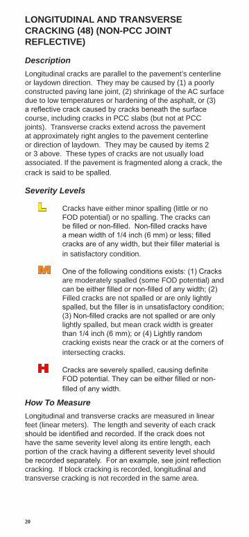
LONGITUDINAL AND TRANSVERSE CRACKING (48) (NON-PCC JOINT REFLECTIVE)
Description Longitudinal cracks are parallel to the pavement’s centerline or laydown direction. They may be caused by (1) a poorly constructed paving lane joint, (2) shrinkage of the AC surface due to low temperatures or hardening of the asphalt, or (3) a reflective crack caused by cracks beneath the surface course, including cracks in PCC slabs (but not at PCC joints). Transverse cracks extend across the pavement at approximately right angles to the pavement centerline or direction of laydown. They may be caused by items 2 or 3 above. These types of cracks are not usually load associated. If the pavement is fragmented along a crack, the crack is said to be spalled.
Severity Levels
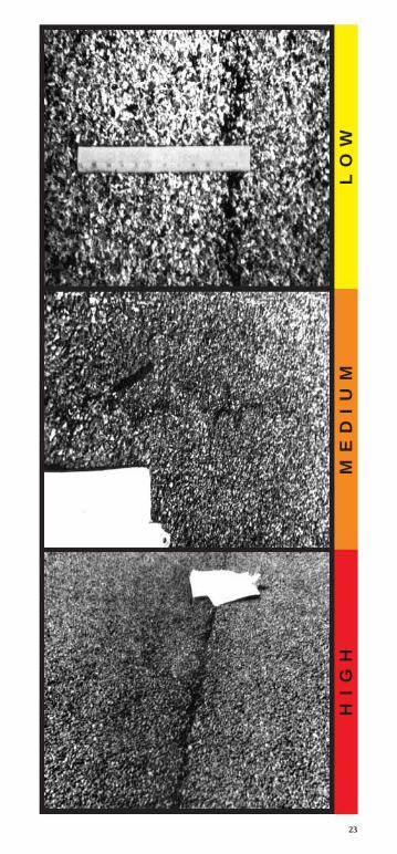
L Cracks have either minor spalling (little or no FOD potential) or no spalling. The cracks can be filled or non-filled. Non-filled cracks have a mean width of 1/4 inch (6 mm) or less; filled cracks are of any width, but their filler material is in satisfactory condition.
M One of the following conditions exists: (1) Cracks are moderately spalled (some FOD potential) and can be either filled or non-filled of any width; (2) Filled cracks are not spalled or are only lightly spalled, but the filler is in unsatisfactory condition; (3) Non-filled cracks are not spalled or are only lightly spalled, but mean crack width is greater than 1/4 inch (6 mm); or (4) Lightly random cracking exists near the crack or at the corners of intersecting cracks.
H Cracks are severely spalled, causing definite FOD potential. They can be either filled or non-filled of any width.
How To Measure Longitudinal and transverse cracks are measured in linear feet (linear meters). The length and severity of each crack should be identified and recorded. If the crack does not have the same severity level along its entire length, each portion of the crack having a different severity level should be recorded separately. For an example, see joint reflection cracking. If block cracking is recorded, longitudinal and transverse cracking is not recorded in the same area.
20

H I
G H
M
E D
I U
M
L O
W
48 L
ON
G. C
RA
CK
ING
21

LONGITUDINAL AND TRANSVERSE CRACKING (48) (NON-PCC JOINT REFLECTIVE) (CONTINUED)
Porous Friction Course Severity Levels Note: These severity levels are in addition to the existing definitions.
L Average raveled area around the crack is less than 1/4 inch (6 mm) wide.
M Average raveled area around the crack is 1/4 to 1 inch (6 to 25 mm) wide.
H Average raveled area around the crack is greater than 1 inch (25 mm) wide.
How To Measure Longitudinal and transverse cracks are measured in linear feet (linear meters). The length and severity of each crack should be identified and recorded. If the crack does not have the same severity level along its entire length, each portion of the crack having a different severity level should be recorded separately. For an example, see Joint Reflection Cracking. If Block Cracking is recorded, Longitudinal and Transverse Cracking is not recorded in the same area.
22
H
I G
H
M E
D I
U M
L
O W
23
OIL SPILLAGE (49)
Description Oil spillage is the deterioration or softening of the pavement surface caused by the spilling of oil, fuel, or other solvents.
Severity Levels No degrees of severity are defined. It is sufficient to indicate that oil spillage exists.
How To Measure Oil spillage is measured in square feet (square meters) of surface area. A stain is not a distress unless material has been lost or binder has been softened. If hardness is approximately the same as on surrounding pavement, and if no material has been lost, do not record as a distress.
24

49 O
IL S
PIL
LAG
E
25

PATCHING AND UTILITY CUT PATCH (50)
Description A patch is considered a defect, regardless of how well it is performing.
Severity Levels
L Patch is in good condition and is performing satisfactorily. Little or no FOD potential.
M Patch is somewhat deteriorated and affects riding quality to some extent. Some FOD potential.
H Patch is badly deteriorated and affects riding quality significantly or has high FOD potential. Patch needs replacement.
The use of dense-graded AC patches in PCC surfaces causes a water damming effect at the patch that contributes to differential skid resistance of the surface. Low severity, dense-graded patches should be rated as medium severity because of the differential friction problem. Medium and high severity patches are rated the same as above.
How To Measure Patching is measured in square feet (square meters) of surface area. However, if a single patch has areas of differing severity levels, these areas should be measured and recorded separately. For example, a 25 ft2 (2 1/2 m2) patch may have 10 ft2 (1 m2) medium severity and 15 ft2 (1 1/2 m2) of low severity. These areas would be recorded separately. Any distress found in a patched area will not be recorded; however, its effects on the patch will be considered when determining the patch’s severity level.
A very large patch (area > 2500 ft2 (230 m2)), or feathered-edge pavement, may qualify as an additional sample unit or a separate section.
26

H I
G H
M
E D
I U
M
L O
W
50 P
ATC
HIN
G
27

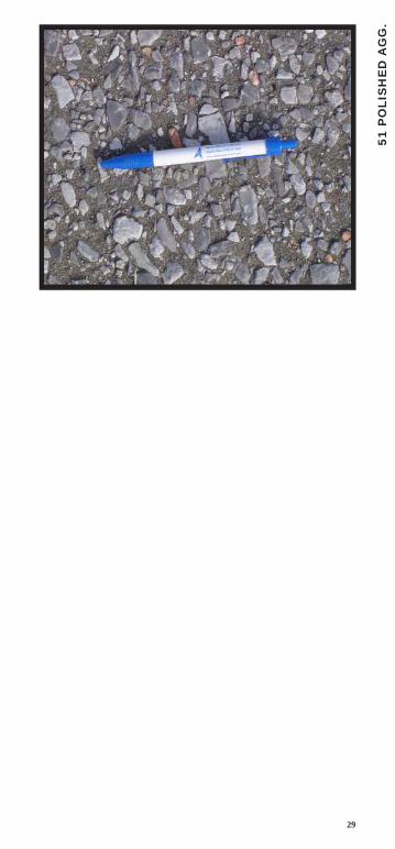
POLISHED AGGREGATE (51)
Description Aggregate polishing is caused by repeated traffic applications. Polished aggregate is present when close examination of a pavement reveals that the portion of aggregate extending above the asphalt is either very small or there are no rough or angular aggregate particles to provide good skid resistance. Existence of this type of distress is also indicated when the number on a skid resistance rating test is low or has dropped significantly from previous ratings.
Severity Levels No degrees of severity are defined. However, the degree of polishing should be significant before it is included in the condition survey and rated as a defect.
How To Measure Polished aggregate is measured in square feet (square meters) of surface area. If bleeding is counted, polished aggregate is not counted in the same area.
28
51 P
OLI
SH
ED
AG
G.
29
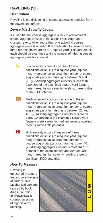
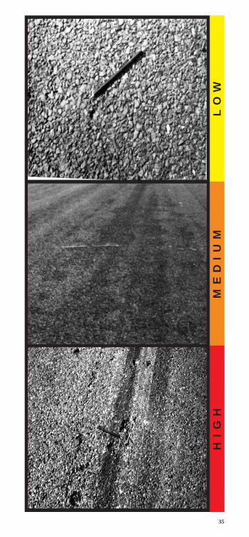
RAVELING (52) Description Raveling is the dislodging of coarse aggregate particles from the pavement surface.
Dense Mix Severity Levels As used herein, coarse aggregate refers to predominant coarse aggregate sizes of the asphalt mix. Aggregate clusters refer to when more than one adjoining coarse aggregate piece is missing. If in doubt about a severity level, three representative areas of 1 square yard (1 square meter) each should be examined and the number of missing coarse aggregate particles counted.
L Low severity occurs if any one of these conditions exist: (1) In a square yard (square meter) representative area, the number of coarse aggregate particles missing is between 5 and 20. (2) Missing aggregate clusters is less than 2 percent of the examined square yard (square meter) area. In low severity raveling, there is little or no FOD potential.
M Medium severity occurs if any one of these conditions exist: (1) In a square yard (square meter) representative area, the number of coarse aggregate particles missing is between 21 and 40. (2) Missing aggregate clusters is between 2 and 10 percent of the examined square yard (square meter) area. In medium severity raveling, there is some FOD potential.
H High severity occurs if any one of these conditions exist: (1) In a square yard (square meter) representative area, the number of coarse aggregate particles missing is over 40. (2) Missing aggregate clusters is more than 10 percent of the examined square yard (square meter) area. In high severity raveling, there is significant FOD potential.
How To Measure Raveling is measured in square feet (square meters) of surface area. Mechanical damage caused by hook drags, tire rims, or snowplows is counted as areas of high severity raveling.
L O
W
30

52 R
AV
ELI
NG
31
H I
G H
M
E D
I U
M
L O
WL
O W
RAVELING (52) (CONTINUED)
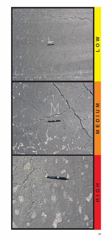
Slurry Seal/ Coal Tar Over Dense Mix Severity Levels
L (1) The scaled area is less than 1 percent. (2) In the case of coal tar where pattern cracking has developed, the surface cracks are less than 1/4 inch (6 mm) wide.
M (1) The scaled area is between 1 and 10 percent. (2) In the case of coal tar where pattern cracking has developed, the cracks are 1/4 inch (6 mm) wide or greater.
H (1) The scaled area is over 10 percent. (2) In the case of coal tar the surface is peeling off.
How To Measure Raveling is measured in square feet (square meters) of surface area. Mechanical damage caused by hook drags, tire rims, or snowplows is counted as areas of high severity raveling.
32
H
I G
H
M E
D I
U M
L
O W
33
RAVELING (52) (CONTINUED)
Porous Friction Course Severity Levels
L In a 1 square foot (1/10 square meter) representative sample, the number of aggregate pieces missing is between 5 and 20 and/ or the number of missing aggregate clusters does not exceed 1.
M In a 1 square foot (1/10 square meter) representative sample, the number of aggregate pieces missing is between 21 and 40 and/ or the number of missing aggregate clusters is greater than 1 but does not exceed 25 percent of the area.
H In a 1 square foot (1/10 square meter) representative sample, the number of aggregate pieces missing is over 40 and/ or the number of missing aggregate clusters is greater than 25 percent of the area.
How To Measure Raveling is measured in square feet (square meters) of surface area. Mechanical damage caused by hook drags, tire rims, or snowplows is counted as areas of high severity raveling.
34
H
I G
H
M E
D I
U M
L
O W
35
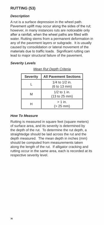
RUTTING (53)
Description A rut is a surface depression in the wheel path. Pavement uplift may occur along the sides of the rut; however, in many instances ruts are noticeable only after a rainfall, when the wheel paths are filled with water. Rutting stems from a permanent deformation in any of the pavement layers or subgrade. It is usually caused by consolidation or lateral movement of the materials due to traffic loads. Significant rutting can lead to major structural failure of the pavement.
Severity Levels Mean Rut Depth Criteria
Severity All Pavement Sections
L 1/4 to 1/2 in. (6 to 13 mm)
M 1/2 to 1 in. (13 to 25 mm)
H > 1 in. (> 25 mm)
How To Measure Rutting is measured in square feet (square meters) of surface area, and its severity is determined by the depth of the rut. To determine the rut depth, a straightedge should be laid across the rut and the depth measured. The mean depth in inches (mm) should be computed from measurements taken along the length of the rut. If alligator cracking and rutting occur in the same area, each is recorded at its respective severity level.
36

H I
G H
M
E D
I U
M
L O
W
53 R
UT
TIN
G
37

SHOVING OF ASPHALT PAVEMENT BY PCC SLABS (54)
Description PCC pavements occasionally increase in length at ends where they adjoin flexible pavements (commonly referred to as “pavement growth”). This “growth” shoves the asphalt or tar surfaced pavements, causing them to swell and crack. The PCC slab “growth” is caused by a gradual opening of the joints as they are filled with incompressible materials that prevent them from reclosing.
Severity Levels As a guide, the swell table below may be used to determine the severity levels of shoving. At the present time, no significant research has been conducted to quantify levels of severity of shoving.
Shoving Criteria
Severity Height Differential L < 3/4 in.
(< 19 mm) M 3/4 in. to 1 1/2 in.
(19 mm to 38 mm) H > 1 1/2 in.
(> 38 mm)
L A slight amount of shoving has occurred, with little effect on ride quality and no breakup of the asphalt pavement.
M A significant amount of shoving has occurred, causing moderate roughness or breakup of the asphalt pavement.
H A large amount of shoving has occurred, causing severe roughness or breakup of the asphalt pavement.
How To Measure Shoving is measured by determining the area in square feet (square meters) of the swell caused by shoving.
38

H I
G H
M
E D
I U
M
L O
W
54 S
HO
VIN
G
39

SLIPPAGE CRACKING (55)
Description Slippage cracks are crescent or half-moon shaped cracks having two ends pointed in the direction of traffic. They are produced when braking or turning wheels cause the pavement surface to slide and deform. This usually occurs when there is a low strength surface mix or poor bond between the surface and next layer of pavement structure.
Severity Levels No degrees of severity are defined. It is sufficient to indicate that a slippage crack exists.
How To Measure Slippage cracking is measured in square feet (square meters) of surface area.
40

55 S
LIP
PAG
E
41

SWELL (56)
Description A swell is characterized by an upward bulge in the pavement’s surface. A swell may occur sharply over a small area or as a longer, gradual wave. Either type of swell can be accompanied by surface cracking. A swell is usually caused by frost action in the subgrade or by swelling soil, but a small swell can also occur on the surface of an asphalt overlay (over PCC) as a result of a blowup in the PCC slab.
Severity Levels
L Swell is barely visible and has a minor effect on the pavement’s ride quality as determined at the normal aircraft speed for the pavement section under consideration. (Low severity swells may not always be observable, but their existence can be confirmed by driving a vehicle over the section at the normal aircraft speed. An upward acceleration will occur if the swell is present).
M Swell can be observed without difficulty and has a significant effect on the pavement’s ride quality as determined at the normal aircraft speed for the pavement section under consideration.
H Swell can be readily observed and severely affects the pavement’s ride quality at the normal aircraft speed for the pavement section under consideration.
How To Measure The surface area of the swell is measured in square feet (square meters). The severity rating should consider the type of pavement section (i. e., runway, taxiway, or apron). For example, a swell of sufficient magnitude to cause considerable roughness on a runway at high speeds would be rated as more severe than the same swell located on the apron or taxiway where the normal aircraft operating speeds are much lower. The following guidance is provided for runways:
Swell Criteria
42
Severity Height Differential L < 3/4 in.
(< 19 mm)
M 3/4 to 1 1/2 in. (19 to 38 mm)
H > 1 1/2 in. (> 38 mm)

56 S
WE
LL
43
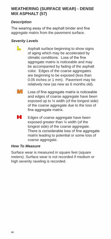
WEATHERING (SURFACE WEAR) - DENSE MIX ASPHALT (57)
Description The wearing away of the asphalt binder and fine aggregate matrix from the pavement surface.
Severity Levels
L Asphalt surface beginning to show signs of aging which may be accelerated by climatic conditions. Loss of the fine aggregate matrix is noticeable and may be accompanied by fading of the asphalt color. Edges of the coarse aggregates are beginning to be exposed (less than 0.05 inches or 1 mm). Pavement may be relatively new (as new as 6 months old).
M Loss of fine aggregate matrix is noticeable and edges of coarse aggregate have been exposed up to ¼ width (of the longest side) of the coarse aggregate due to the loss of fine aggregate matrix.
H Edges of coarse aggregate have been exposed greater than ¼ width (of the longest side) of the coarse aggregate. There is considerable loss of fine aggregate matrix leading to potential or some loss of coarse aggregate.
How To Measure Surface wear is measured in square feet (square meters). Surface wear is not recorded if medium or high severity raveling is recorded.
44

H I
G H
M
E D
I U
M
L O
W
57 W
EA
TH
ER
ING
45


1
2
3
4
5
6
7
8
9
10
11
12
13
14
15
16
17
18
Ocm.
O in.
1
2
3
4
5
6
7