application to steel ingot manufacturing from casting to ...©s/2016-icfg... · advanced solutions...
TRANSCRIPT

Advanced solutions for virtual process modelling: application to steel
ingot manufacturing from casting to open-die forging
JAOUEN Olivier1,a, COSTES Frédéric1,b , SAAD Ali1,c and LASNE Patrice1,d
DUCLOUX Richard1,e * , 1TRANSVALOR SA
Parc de Haute Technologie – 694 avenue Dr Maurice Donat
06255 Mougins Cedex – France
Keywords: fluid-structure model, turbulent flow, segregations, grain structure, cellular automata (cafe), complete manufacturing process chain, ingot casting & open-die forging simulation, heat treatment.
Abstract. The health of forged components depends on the quality of the semi-product previously
issued from casting process. In that context, a numerical simulation tool able to master material
characteristics from initial casting to the final forming process would be of a great interest for steel
makers and forging manufacturers. This is the purpose of the present paper. Nowadays, it is well
known that ingot defects like hot tears or cracks are rooted in the very beginning of the solid shell’s
birth. Damages are resulting from the competition between the hydrostatic pressure occurring within
the turbulent flow in the liquid zone and tensile stress combined with a strain state occurring while
the skin solidifies. In addition, the thermal energy pulled-out from the cast-metal product into the
mold has a huge impact on the shell’s thickness. This thermal energy is also affected by the air gap
growth issued from the shrinkage of the solidified together with the deformation of the mold
constituents. Numerically speaking, the fluid/structure model is one of the most appropriate
methods to take into consideration all these phenomena through an accurate way. Indeed, a standard
CFD method does not represent the solid behaviour, so that the stresses, strains and air gap
evolution due to the shell’s shrinkage are not reachable. On the other hand, a single standard FEA
model cannot represent accurately the liquid behaviour.
In a first part, this paper describes a new 3D fluid/structure model involving the turbulent fluid flow
and the solid constitutive equation. The management of the “liquid time step” allowing high
velocity motion into the liquid phase of the alloy coupled with the “solid time step” dealing with the
solid phase and the corresponding slow motion is shown. Moreover, the fluid-structure model is
well adapted to localize segregation especially when using quality input data delivered by thermo-
dynamic databases. An applicative example with an ingot casting considering the coupling with the
deformation of the mold is presented. On top of that, the example includes grain structure
calculation resulting from a CAFE method coupled with the cooling of alloy. It also illustrates the
impact of a top powder defined as a deformable body and therefore able to follow the shrinkage of
the ingot top surface. The exothermic reaction is considered as well in order to estimate its impact
on the cooling time and the final quality of the cast-metal product.
In a second part, the paper describes the benefits of simulating the complete manufacturing chain
from initial casting to open-die forging and final quenching. A direct data transfer from casting to
forging is performed between the simulation tools. All results from the casting stage are so
considered into the forging model. Both casting & forging models are fully compatible. Hence, there
is not any loss of data in the transition step and the forging process simulation launch is seen as a
simple restart step from the casting simulation. In that context, data like global shape, porosities,
segregation distribution issued from the casting are accounted in the forging process in order to fully
monitor the history and their impact on the final product’s health. The modelling of the forging
stage allows estimating the efficiency of the manufacturing process with regards to the closure of
porosities and the tracking of segregations. In addition, the carbon rate concentration coming from
the casting stage and transferred into the subsequent forging stage will impact the solid phase
changes occurring in the final quenching operation. The simulation of this phenomenon is possible
considering an appropriated heat treatment model based on TTT diagrams which depend on the
local carbon concentration. Finally, this paper demonstrates how steel makers and forging
manufacturers can take benefit of full compatible process modelling software in order to simulate
the entire the forming chain from raw material to final end-user product.
Introduction
The heavy industry, petrochemical and/or the nuclear, uses largely the shells as high pressurized
container. These shells are obtained after a sequence of multiple operations that may involve
different methods. The sequence can start from solid ingots. It can also assemble rolled and welded
sheet metal, or can use hollow ingots. Compared to the other methods, the sequence starting from
hollow ingot presents certain advantages. Indeed, in that context, as opposed to the method using
rolled and welded sheets, the final product that is one piece avoids weaknesses in welded areas. On
the other side, on the contrary to the process starting from a full ingot, it gains a screwing operation.
In addition, since the porosities are in the core of the shell and not at skin area, they can be better
controlled way during the becking operation yielding a better quality product. The final segregation
distributions are still easier a lot to anticipate. However, in spite of all these advantages, all is not
perfect in this model. Indeed, by its hollow nature, in order to obtain the requested qualities of the
final product, the solidification of the ingot must be perfectly mastered. Thus, a specific and
complex cooling is applied to the inner wall of the ingot aiming at obtain symmetrical
characteristics between its inner and outer walls. This can be yielding from controlled circulation of
water or blown fresh air. In order to fully carry out all of this chain, a simulation tool can be of great
help in this process. It allows optimizing the cooling time, to regulate the inner cooling or to
estimate the intern structure. Moreover, it can be helpful in the forging operations in the
determination of the sequence of strokes, and many things else. However this involves the capability
to simulate the entire sequence of different operations from the ingot casting to the heat treatment
passing through the mandrel drawing.
In this paper a numerical model able to perform the simulation of all these successive operations is
presented. It shows the perfect and natural chaining between an ingot casting simulation software
and an open die forging software. Through a dedicated example, the authors show how the specific
conditions of cooling of the ingot are taken into account through the implementation of thermo-
mechanical interfaces boundary conditions. The impact of air gap on temperature change and the
reverse effect on the ingot shape are particularly highlighted. They illustrate the same, how
porosities and segregations are on the one hand determined by the casting software and on the other
hand, naturally transferred to forging software. Thus, the monitoring of their evolution and their
impact on the mechanical behavior and on the structure of the final product is perfect. Mandrel
drawing and becking operations are shown including the example of the closure of porosities. At
end, the distribution of local segregation is taken into account in order to illustrate the impact of
phase changes during the heat treatment operation.
Finally, this article presents the strategic interest of a simulation tool capable of predicting the
overall process of making a shell from a hollow ingot for casting ingot, cooling and its forging.
Authors propose a coupling between the two products to have an advanced numerical suite for the
design of such components. This coupling will allow to produce parts meeting the requirements of
high levels of nuclear and petrochemical industries as well as to limit the actual tests representing a
significant material savings regarding the volumes and mass of the parts involved.

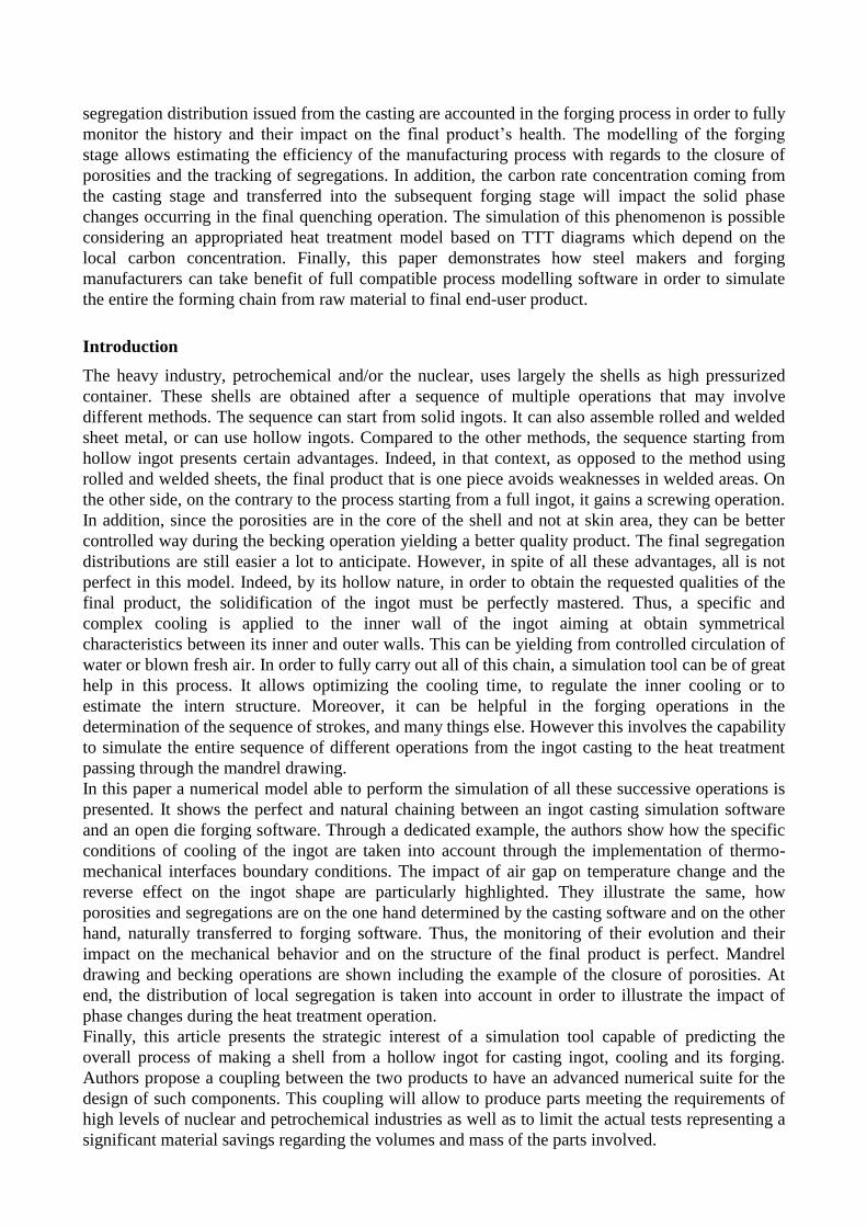
Ingot casting Mandrel drawing Becking
Fig 1: Example of the making chain of a shell from hollow ingot. Final part is obtained after
casting of a hollow ingot, mandrel drawing operation, then becking operation. Heat treatment
operation is not presented here, but could be also performed
Case context
The case illustrated in this article was built internally from the knowledge of our engineering
experts. Only the initial CAD files for ingot casting step computation were provided by one of our
industrial partners.
The material of the shell is 40CMD8. Dimensions of the initial ingot are presented Fig. 2. Its weight
is of 140 tons. The casting step is a bottom pouring process through a running system spited in 3
feeding gates (Fig. 4). The flow rate is set such that the speed of the flow front represents
100mm/min. The initial temperature is 1550°C. Once the ingot tripped out, the cut of the riser and
the bottom yields a piece which height is 3 m. It will be stretched till 4 m at the end of the mandrel
drawing process.
Ingot casting Mandrel drawing
Fig 2: Dimensions of the cast ingot, and after the drawing and becking steps.
Casting process
Fluid/Structure model
The simulation of the casting process requires a specific treatment of the different phase changes
of metal, liquid, mushy and solid, from the beginning of pouring to the end of solidification. By
default, the casting software calculates evolution of temperature in the cast product and the different
components of the cooling system, the mold, the casting plates, and other refractory or insulating
cover powder, etc. This is performed using a dedicated model.
At any time, the mechanical equilibrium is governed by the general momentum equation:
Heat
Treatment
Machining

0. γgσ . (1)
where σ is the Cauchy stress tensor, g is the gravity vector, and γ is the acceleration vector.
The very different behaviours of liquid and solid metal are considered by a clear distinction
between constitutive equations associated to the liquid, the mushy and the solid states respectively.
In order to fit the complex behaviour of solidifying alloys, a hybrid constitutive model is accounted.
The liquid (respectively, mushy) metal is considered as a thermo-Newtonian (respectively thermo-
viscoplastic, VP) fluid. In the solid state, the metal is assumed to be thermo-elastic-viscoplastic
(EVP). However, this scheme has a drawback. Indeed, the resolution is carried out in one shot,
taking account the total range of temperature. Due to the limits of actual algorithms and hardware
precision, it cannot consider the corresponding total magnitude of concerned viscosity. In order to
deal with the very large range of the viscosity values involved within the solidification process of
the molten alloy, a two steps scheme is used for the solving of (1). Hence, one step, step 1, is
dedicated to the mushy and solid zones, the “solid solver”, and another one, step 2, is in charge of
the liquid and mushy zones, the “liquid solver” (Fig 3). Solid regions are treated in a Lagrangian
formulation, while liquid regions are treated using an ALE (Arbitrary Lagrangian Eulerian) method
[2]. A so called, transient temperature, or coherency temperature, is distinguishing the two different
behaviours. It is typically defined in between liquidus and solidus, and usually set close to solidus.
Thermo-physical parameters are setup such that the continuity of behaviour is ensured at transient
temperature. For more information, the interested reader can refer to [3] to [5]. Under that context,
two cases are possible. Option 1, the transient temperature bounds the two steps. The full coupling
liquid/solid is ensured by the control of liquid velocities and pressure with the solid corresponding
ones at “transient temperature volume interface” [6]. Option 2, an overlap within the mushy zone is
also available. Yield, both “liquid solver” and “solid solver” are applied on the total or partial range
between liquidus and solidus (Fig. 3). In addition, any governing model can be associated to each
solver. In particular, turbulent fluid flow within the liquid zone of the metal is managed by the
Navier-Stokes equations completed by LES terms [7].
Fig 3: Schematic representation of the option 2 for the 2 steps algorithm. The high level of
temperature for the step 1 (Tstep1) is within the mushy zone range. Same, the low level of
temperature for the step 2 (Tstep2) is within the mushy zone, such that Tstep 1> Tstep2. In case of
Tstep1 = Tstep2, it is similar to the option 1. The choice of the two temperatures Tstep1 and Tstep2
is depending on the structure of the alloy within the mushy zone, typically, it can depend on the
viscosity and/or the solid fraction and the composition.
In that scheme, the step 2 of the algorithm is not only dealing with the liquid metal, but also with
the air within the cavity till this one is fulfilled. This is possible thanks the use of a level-set method.

Level-set represents the distance )(t to the interface )(t
between fluids at time t , here liquid
metal and air; its expression is:
)(/))(,(),(
)(0),(
)())(,(),(
tintxdisttx
tontx
tintxdisttx
(2)
where is the cavity space, )(t is the space occupied by the metal into the cavity, and )(/ t is
the remaining space, meaning the air space. Considering definition (2), flow front of the metal is the
0 value iso-surface of )(t [6], [7].
Thermal model
The solving of the general energy equation drives heat transfers:
))(.()(
TTdt
TdH (3)
where T is the temperature, (W/m/°C) denotes the thermal conductivity and H (J) the enthalpy
which can be defined as:
)()()()()(
0
s
T
T
lp TLTgdCTH (4)
0T (°C) is an arbitrary reference temperature, (kg/m
3) the density, sT (°C) the solidus temperature,
pC (J/kg/°C) the specific heat, lg the volume fraction of liquid, and L (J/kg) the specific latent heat
of fusion. In the one-phase modeling, )(Tgl can be previously calculated using the micro-
segregation model PTIMEC_CEQCSI [8] or results from micro-segregation model that can be used
[9].
Cooling conditions
One of the difficulties in the casting of the hollow ingot is the cooling control. In particular, the
cooling of the inner side represents a king of challenge. Indeed, in the end of the solidification, the
intern structure of the ingot must be as symmetric as possible compared to the outer side. However,
the building of the cooling system is rather asymmetric: the inner side is a thin wall whereas the
outer side is a wide cast iron mold. Therefore, the difference of mold constitution between inner
side and outer side has impact on solidification. That very difference must be balanced by the
cooling conditions. This requires a perfect control of the inner cooling. Typically, what are usually
considered are either water channels or air blowing. In our case, fresh air blowing all over the
surface of the inner wall has been chosen. This is carried out numerically speaking by a specific heat
transfer coefficient, representing the blow effect (Fig. 5).

Fig 4: Illustration of the ingot shape. Note the three feeder gates.
Fig 5: illustration of the configuration of computation. A symmetry plan has been used in view of
the geometry of the casting. To fully address the evolution of the temperature through the various
system components casting, a fine mesh is adapted in the insulating parts such as refractory and
garnex parts. Similarly, the part of the mesh running system is refined to manage the flow. The
various mechanical and thermal boundary conditions are indicated. They allow to take into account
the interactions between the various components of the casting system with one another and with
ambient.
The boundary conditions applied on free surface of the mesh of the different parts of the cooling
system are of classical different types:
average convection: )(n. extTThT where h (W/m²/°C) is the heat transfer
coefficient, and extT is the ambient temperature
radiation: )(n.44
extstef TTT , where is the steel emissivity, stef is the Stephan
– Boltzmann constant.
external imposed temperature: impTT .
external imposed heat flux: impT n. n denotes the outward normal unit vector.
Thermal transfers Mechanical transfers
At ingot/mold interface : - Specific heat
transfers depending
on the mold nature
- Air gap/pressure
dependent heat
transfers
At mold/mold interface : - Specific heat
transfers depending
on the molds’ nature
Blown fresh air cooling
At ingot/mold interface: - Sticky liquid
- Friction for mushy
and solid phases
Deformable exothermic powder follows the metal shrinkage

At part/molds interface, heat transfers are taken into account with a Fourier type equation:
)(1
n. mold
eq
TTR
T (5)
where moldT is the interface temperature of the mold and eqR (W/m²/°C) 1 , the heat transfer
resistance that can depend on the air gap and/or the local normal stress, as presented below:
011
10
)11
,1
min(
1
00
airseqairs
radair
eq eifR
RR
RoreifR
RRR
R
(6)
where air
air
air
eR
and
s
s
s
eR
with aire and se respectively the air gap and an eventual other body
(typically mold powder) thickness and air and s the air and the eventual other body thermal
conductivity. 0R is a nominal heat resistance depending on the surface roughness,
))((
111
22
moldmoldstef
mold
radTTTT
R
with mold the emissivity of the mold, m
nAR 1 a heat
resistance taking into account the normal stress n , A and m being the parameters of the law.
Through (5), (6), the full thermal/mechanical coupling within the casting system is ensured. Indeed,
the cooling of the solidifying alloy implies external shrinkage that creates air gap at ingot/mold
interface. This air gap behaves as a local insulator and modifies heat exchanges locally in time and
space between ingot and mold which in return modifies the cooling of the alloy and so the
shrinkage. This is only possible because thermomechanical computation is performed and (5) is
used as boundary condition. An a priori input of heat transfer coefficient does not allow this full
coupling.
Prediction of the defects and the structure of the cast product
The strength of the above thermo-mechanical model allows combining different cast product health
prediction models. Indeed, to the liquid/mushy models is associated a segregation model. To the
mushy/solid models is associated a cracks/hot tears prediction model. This is possible thanks to the
full coupling between liquid and solid behaviors considered via the mix of the dedicated thermo-
mechanical models that are solved in the two steps model above (Fig. 6,7,8,9 and 10).

Fig 6: illustration of the temperature distribution in four different instants of the filling. The
horizontal line indicates the level of metal in the mold. The arrows demonstrate the movements of
the liquid metal. Note the mold heating by the advancing metal during pouring.
Fig. 7: Illustration of the final configuration of the calculation. One can notice the shape of the
covering powder in the end of solidification which is deformed according to changes in the free
surface of the ingot. On the right, the final shape of the ingot with the primary shrinkage. The radial
symmetry of the ingot confirms that the cooling at inner side wall of the casting system has been
calibrated and well controlled.

Fig. 8: illustration of the distribution of the final temperature in the casting system. One can notice
the non-continuity of the temperature at the interface between the ingot and the mold showing the
recognition of the impact of the air gap on heat transfer. Indeed, the air gap acts as an insulator
which slows down the evacuation of the heat energy from the ingot to the mold resulting in a
temperature difference at ingot/mold interface (5). The air gap is particularly visible by the dark line
that can be seen at that very interface.
Fig. 9: illustration of the evolution of carbon segregations at different times of process. It may be
noted that segregation begins as soon as the filling phase in liquid and mushy metal areas.
Fig. 10: Illustration of the ferrostatic pressure in the liquid portion of the solidifying metal (left).
The distribution of pressure in layers according to the height of the ingot (gravity direction) shows
that the behavior of the liquid portion of the metal is fully taken into account in the calculation. The
thin lines represent the mushy zone separating the liquid from the solid. Distribution of the first
principal stress (right). Positive values mainly shows the tensile state of the areas. On the other
hand, the absence of air space around the central sleeve indicates that the ingot is contracted mainly
around the sleeve, a priori expected results in this configuration.

Connection with forging phase
The simulation of the complete chain of the making process involves that a lossless transfer
between the casting and the forging steps is performed [10], [11], [12]. Only the fact that the two
software are sharing the same core structure ensures such a fully compatibility of results. This
transfer operation between the two products is therefore simple and natural way. Thanks to this
coupling between the casting software and the forging one, the results at the end of solidification are
transferred to the calculation of forging to start drawing pass with precise distributions. In particular,
the criteria for porosity, segregation and concentrations of chemical elements are passed to forging
software. It is therefore understood the value of such a coupling in tracking developments resulting
from casting step. For example, the prediction of porosity closing in forging step will rely on a
starting distribution that is the end of casting calculation (Fig.11). Similarly, by transferring
concentrations of chemical elements, it will be possible to follow the carbon impoverished and
enriched areas during all subsequent forging operations.
For the treated case, the transfer operation will also consist in cutting the riser and feed channels of
the mesh resulting from casting step. Then all of the mesh of the sleeve (360°) is performed by
symmetrization.
Fig. 11: Example and results transferred from casting software to forging during transition between
the casting process and the forging process. On the left, areas of high risk of presence of porosities.
On the right, the distribution of the carbon concentration at the end of solidification
Forging step
The incremental forging operations on the hollow ingot will allow to obtain the final geometry
but also to impart metallurgical and mechanical properties to the piece. For example, one has to
ensure that at the end of the forging porosities will be closed. These forging operations and their
control therefore fall of great importance both in the quality and life of the final component and on
the financial aspects. Also, it is easy to understand the strategic investment that represents the
numerical simulation as an aid to design for the manufacture of this type of product: validation of
the set of strokes, prediction of the number of heaters, dimensional prediction, prediction of
mechanical and metallurgical properties.
The hollow ingot will undergo two forging operations: a drawing operation on the mandrel to
stretch from a length of 3m to 4m length while maintaining a certain thickness. Then an operation of
becking to expand its diameter from 1800m to 2100m will be carried out. The drawing mandrel
operation will also help closing the porosities potentially present at the end of solidification.
Similarly to the casting software, the model used in the forging software to represent the material
behavior is EVP. Thermal and mechanical phenomena are solved in a coupled manner.
The drawing mandrel is comprised of a single pass, and 114 shots are given. Between each shot
piece undergoes either a rotation or a translation. Similarly, a becking pass of 240 shots is made

with a rotation of 20° of the ring between each blow. Given the high number of movements of the
shell between shots, it is understandable that the difficulties of the numerical simulation for this type
of process will be to communicate effectively all these movements to the workpiece; movement
during which there is no plastic deformation. Note that is generally true for all open die forging
processes. This is actually possible in the forging software through the use of a dedicated control
file in which the details of each pass the number of strokes, movement and rotation of the part, the
waiting time is specified. The link between the drawing simulation results and becking simulation is
provided naturally through chaining operation. This ensures the transport of any thermo-mechanical
history between the two steps of the forging process.
Fig. 12 shows how the surface including areas with high risk of the presence of porosities, coming
from casting process (Fig 11, left), is evolving in different stages of stretching, in the beginning,
during and at the end. Numerical simulation allows to check the closure of porosities during the
forging operation.
Fig. 12: Evolution of the area (blue area) with high risk of porosity during drawing. Note that
porosities are closed at the end of stretching.
Fig. 13: illustration of the evolution of equivalent plastic strain at 50% (left) and in the end of the
drawing (right)

Fig. 14: Distribution of carbon in the end of drawing (carbon-depleted zone corresponds to the foot
of the ingot and carbon-enriched zone corresponds to the top of the hollow ingot) and consideration
of offset curves TRC.
Along with the closure of porosities, Fig. 13 shows the evolution of the equivalent plastic strain
during the process. It is interesting to remark that, if one would have considered the process starting
from a full ingot, the situation would have been rather different from the present one. Indeed, the
process would have requested a screwing step more. But, which would have been really different is
the distribution of porosities at the beginning of the drawing step localized closed to the mandrel,
almost at contact. This results from initial distribution into the full ingot that is at central axis. Now,
if one considers the range of equivalent plastic strain Fig. 13 at mandrel contact area, it appears
much lower than at intermediate level and much lower again than at outside surface. That means
that closure of porosities localized at mandrel contact area requests a much higher forging power
than the one in the present case. Consequently, if it is possible to reach the same level of final
product quality starting from a full ingot, that needs more steps within the whole process, like
screwing step and certainly machining process, hence higher costs.
Monitoring concentration maps of different chemical elements from the solidification phase and
during the drawing operation is ensured by the coupling between the two software. The distribution
of chemical elements at the end of forging is determined so that allows a more accurate calculation
of subsequent heat treatment operations. In this respect, Fig. 14 shows the distribution of carbon in
the end of drawing, after being initialized by the distribution coming from casting phase (Fig 11,
right), and the influence of the variation of the rate of carbon on the CCT diagram.
As explained above, the automatic transfer from drawing to becking is carried out through a
numerical chaining. Then the becking step is launched. Fig. 15 illustrates the distribution of
temperature during this operation.
Once the forging process completed, heat treatment can be also treated in the end of the becking
operation, taking account the carbon distribution, this one being transported all over the process.
C=0,25 C=0,44

Fig. 15: Distribution of temperature during the becking step of the process.
Conclusion
THERCAST®, a casting software, and FORGE®, a forging one, are both industrially used. They
allow determining the thermo-mechanical behavior of the cooling metal in ingot casting and open
die forging processes. This paper shows the interest of coupling between the two software, which is
a powerful tool as an aid in the design of shells produced from hollow ring. This coupling provides
a software solution to monitor the complete process chain, the prediction of porosities, segregations,
concentrations of chemical elements during solidification to their evolution during the phases of
forging. It gives a better understanding of the internal structure of the forged part. This example
illustrates how nowadays numerical models could be used in the steel industry to improve the
quality of production and the productivity. Moreover, one shows how the process starting from a
hollow ingot in the shell making can be better than starting from rolled and welded sheets or full
ingot. With such simulation tools, steel makers are able to control and optimize their process.
Besides, this tool is thus evolving. Indeed, it is continuously enriched through the implementation of
new models from applied research and adding new features.
References
[1] M. Bellet et al., Proc. Int. Conf. On Cutting Edge of Computer Simulation of Solidification and
Casting, Osaka, The Iron and Steel Institute of Japan, pp 173 – 190, 1999.
[2] M. Bellet, V.D. Fachinotti, ALE method for solidification modelling, Comput. Methods Appl.
Mech. and Engrg. 193 (2004) 4355-4381.
[3] O. Jaouen, Ph D. thesis, Ecole des Mines de Paris, 1998.
[4] F. Costes, Ph D. thesis, Ecole des Mines de Paris, 2004.
[5] M. Bellet et al, Proc. Int. Conf. On Cutting Edge of Computer Simulation of Solidification and
Casting, Osaka, The Iron and Steel Institute of Japan, pp 173 – 190, 1999.
[6] M. Bellet, O. Boughanmi, G. Fidel, A partitioned resolution for concurrent fluid flow and stress
analysis during solidification: application to ingot casting, Proc. MCWASP XIII, 13th Int. Conf. on
Modelling of Casting, Welding and Advanced Solidification Processes, Schladming (Austria), June
17-22, 2012, A. Ludwig, M. Wu, A. Kharicha (eds.), IOP Conference Series 33 (2012) 012052, 6
pages
[7] G. François, Ph D. thesis, Ecole des Mines de Paris, 2011.
[8] N. Triolet et al, The thermo-mechanical modeling of the steel slab continuous casting: a useful
tool to adapt process actuators, ECCC 2005.
[9] A. Kumar, M. Zaloznik, H. Combeau,International Journal of Thermal Sciences, vol. 54, 33-47
(2012)
[10] Jean-Loup Chenot et al., Advanced Numerical methods for F.E. Simulation of Metal Forming
Process

[11] Jean-Loup Chenot et al. Numerical Simulation and Optimization of the Forging Process, ICFC
Proceedings
[12] Patrice Lasne, Simulation in open die forging operations, Transvalor internal report (2009)