effect of mould material on aluminum alloy ingot quality under … · 2009-04-01 · effect of...
TRANSCRIPT

CHINA FOUNDRY Nov. 2006
288
F or a semi-continuous aluminum casting process, it is essential to supply high quality aluminum alloy ingot
wi thout in te rna l and outs ide defec ts . The use ofelectromagnetic fields to control the size and shape of grainshas become one of the most promising methods [1-5] in manyengineering applications and tends to be widespread inindustries. The application of electromagnetic casting (EMC)technique for improving products quality has attracted a greatdeal of attention in recent years, and considerabledevelopments have been achieved. However, the traditionalEMC always requires elaborate processing control andexpensive devices. In addition to EMC process, low frequencyelectromagnetic casting (LFEC) [6-13], which is simple andefficient, has been developed in the laboratory with thefrequency lower than that in the casting, refining andelectromagnetic process (CREM), which was put forward byVives[14-15] to refine structures and improve the surface quality ofingots.
The mould is important in the casting process, especially in thelow-frequency electromagnetic casting process. A well-designedmould can provide enough magnetic flux density and magneticbody force with less current value, which make the coil serverlong. Based on the demand for the mould for the LFEC, one-strand LFEC model was built and the magnetic flux density and
Effect of mould material on aluminumalloy ingot quality under low frequencyelectromagnetic casting
magnetic body force in the molten aluminum were computed byusing the commercial package ANSYS which is based on thefinite element method (FEM). The effects of different mouldexternal part material on the magnetic flux density and magneticbody force in the molten aluminum were discussed. One-strandlow frequency electromagnetic casting 6063 aluminum alloyexperiment was conducted in the laboratory. The effect of mouldouter part material on surface quality, microstructure under the
low frequency electromagnetic field was systematically studied.
1 Mathematical model establishment
1.1 Low frequency electromagnetic casting
Figure 1 shows the sketch of the LFEC process. The mouldconsists of three parts, an inner, an outer and a graphite part. Thecoil is situated in the place surrounded by the inner, outer andgraphite parts. The graphite mould contacts the molten aluminumdirectly. During steady LFEC process molten aluminum isgradually supplied from top and solid aluminum ingot is graduallywithdrawn from bottom. The air/liquid aluminum and liquid/solidaluminum interface shapes keep the same. Electro-magnetic fluxforce exerts on the liquid aluminum and improves the quality ofingot. In order to investigate the effect of mould outer part materialon ingot quality, two moulds were made. One mould outer partwas made from austenitic stainless steel and its relativepermeability is 1. The other mould outer part was made from A3
steel and its relative permeability is 1 000.
1.2 Mathematical model
The mathematical model is to model the most important area
Male, born in 1972, Ph.D. Currently, being engaged in theresearch on electromagnetic stirring for iron & steel and multiflowlow frequency electromagnetic casting for aluminum alloy.E-mail: [email protected]
Received date:2006-03-25; Accepted date: 2006-09-09
*LI Jian-chao
( 1. Northeastern University, Shenyang 110004; 2. Inner Mongolia University of Science and Technology, Baotou 014010 )
*LI Jian-chao1, 2, CUI Jian-zhong1 , WANG Bao-feng2, MA Yong-lin2
Abstract: With the aid of ANSYS software, the effect of different mould external part materials onmagnetic flux density and electromagnetic body force in the liquid aluminum was investigated. Calculatedresults showed that magnetic flux density and electromagnetic body force in the aluminum melt aregreatly increased when the external part of mould is made from A3 steel. A low-frequency electromagneticcasting 6063 aluminum alloy experiment was conducted in the laboratory with the current value of 120 Aand frequency value of 15 Hz. The experiment showed that the microstructure and surface quality ofingots with mould outer part made from A3 steel under low-frequency electromagnetic field are betterthan that of ingots with mould outer part made from austenitic stainless steel. The surface of the ingotswith mould outer part made from A3 steel is smooth and free from exudations and cold shut defects. Theas-cast microstructure consists of fine, uniformly distributed equiaxed grains.
Key words: Low-frequency electromagnetic casting; finite element method; aluminum alloy; mould materialCLC mumber: TG292/TG146.2 Document Code: A Article ID:1672-6421(2006)04-0288-05

Vol.3 No.4 Research & Development
289
Fig.1 Mould structure and principal of LFEC
in the low frequency electromagnetic casting process: the eddycurrent region Ω
1 full of the conducting media and containing
molten aluminum, mould and graphite, and free of eddy currentarea Ω
2: cooling water, air and coil area.
Electromagnetic field is depicted by the magnetic vectorpotential A as well as the electric scalar potential V, the fieldvectors are obtained from the potentials as:
in Ω2
In these equations, B is magnetic flux density, E is strength ofelectric field, t is time, v=1/µ is magnetic reluctivity, µ ismagnetic conductivity, J
s is current density in induction coil.
The boundary condition is: at the boundary of Ω1 and Ω
2 area,
where n is outer vector normal on the corresponding surface,and the subscripts 1 and 2 refer to quantities in the regions Ω
1
and Ω2, respectively. v
1, v
2, are magnetic reluctivities of Ω
1
and Ω2 respectively. Magnetic line parallel boundary condition
and vertical boundary condition are expressed through thefollowing equations
Therefore software, ANSYS package, is used to solve themathematical equations. The ANSYS uses a combination ofvector and scalar potential to compute electromagnetic field.
Figure 2 shows the elements used for the model. In order toshow the details of the elements, the elements of the air aroundthe device are not given in Fig.2. Hexahedral elements wereused for describing objects except for outside air and inner water.Outside air and inner water were built up by tetrahedral elements.The structure of the elements at the beginning of a simulation isseen from Fig.2. There are 40567 elements and 79536 nodes inthe finite element model. Tables 1 and 2 give the parametersused for the computation of electromagnetic field.
Fig.2 Corresponding meshes of ingot, coil, and mold
The magnetic vector potential at the outer face of air, which isaround the model, is set as zero.
1.3 Numerical calculation
The above mathematical model is very complicated and it isimpossible to obtain analytical solution for the modeled area.
According to Maxwell’s equations, in the eddy current region Ω1
(11)
(10)
Table 1 Parameters for the computation of electromagnetic field
4.0 107
7.14 105
1.0 106
0
1.0 103
1.1 107
Materials
Molten aluminum
Austenitic stainless steel
Graphite
Air (water)
A3 steel
Solid aluminum
Relative permeability
1.0
1.0
1.0
1.0
1 000
1.0
Conductivity
Table 2 Parameters for simulation diameter of ingot
Diameter of ingot
0.174 m
Coil turns
80
Current
120 A
Frequency
15 Hz
Load applied conditions: In the computation process, thesection of coil is loaded with current density j, which isdetermined by current, coil number and section area.
(6)
(7)
(8)
(9)
(1)
(2)
(3)
(4)
(5)
Mouldouterpart
Water
Graphite
Air
Hot top
Mould inner part
Cooling waterfor coil
Second cooling zone water
Coil
Liquid Al
Solid Al

CHINA FOUNDRY Nov. 2006
290
Fig. 3 Comparison between measured (solid triangle) and simulated (hollowed circle) magnetic flux density at radius direction at the middle of the coil in height without load
Fig. 4 Calculated distribution of magnetic flux density in axial section of the aluminum with different mould outer part materials
2 Validation of the modelBefore using the model an experiment was conducted to checkvalidation of the model. In the experiment without load (withoutcast ingot), 120 A and 15 Hz current were used. Magnetic fluxdensity in the radius direction at the middle of coil in height wasmeasured at three different positions (as for in the edge, middleand center of aluminum) using the 5080 Gauss meter made byBell Corp. Figure 3 shows the comparison of calculated (hollowedcircle) and measured (solid triangle) magnetic flux density for themould outer part made from A3 steel. It is shown that there aregood agreements between calculated and experimental data forthe condition without load (without cast ingot). Although the goodagreement was checked without cast ingot, it is believed that themodel is valid for the condition during cast ingot to analyzedistribution of the magnetic flux density in the low frequencyelectromagnetic casting process.
3 Model calculated results analysis and discussion3.1 Effect of mould outer part material on magnetic flux density
Figure 4 shows the model calculated magnetic flux densitydistribution in the molten aluminium in the axial section withouter mould made from austenitic stainless steel (a) and A3 steel(b) respectively. It is seen that for the mould outer part madefrom A3 steel, the magnetic flux density maximum is 0.054 Teslaon the surface of liquid aluminum. For the mould outer part madefrom austenitic stainless steel, the magnetic flux density maximumis 0.04275 Tesla. From the center to the edge of the meltaluminum, the magnetic flux density is increased about 26% forthe mould outer part material made from A3 steel.
When the magnetic flux density generated in the coil penetratesthe liquid aluminum, it meets the electromagnetic resistance inthe high conductivity liquid aluminum as result of induced eddycurrents. These induced eddy currents create its own magneticflux density to prevent the penetration of primary magnetic fluxdensity into the liquid aluminum. The magnetic flux density triesto concentrate at the area near to the surface of the liquidaluminum. The higher the conductivity of the melt is, the lessmagnetic flux density penetrates into the melt and the higher
concentration of magnetic flux density at the area near to thesurface of the melt is.
As we know, the magnetic flux generated by the coils exists inthe coil inner part and the air as well. The magnetic flux haspriority going through the higher relative permeability material.When the mould outer part is made from A3 steel, owing to itshigh relative permeability, the magnetic flux dissipated in the airsurrounding coils will be absorbed and put back into liquidaluminum through the mould outer part. When the mould outerpart is made from Austenitic stainless steel, which has no magneticproperty and whose relative permeability is equal to that of air,so the magnetic flux dissipated in the air will not be changed.The mould outer part made from soft magnetic material such asA3 steel can improve the magnetic flux density in the meltaluminum.
3.2 Effect of mould outer part material on magnetic body force
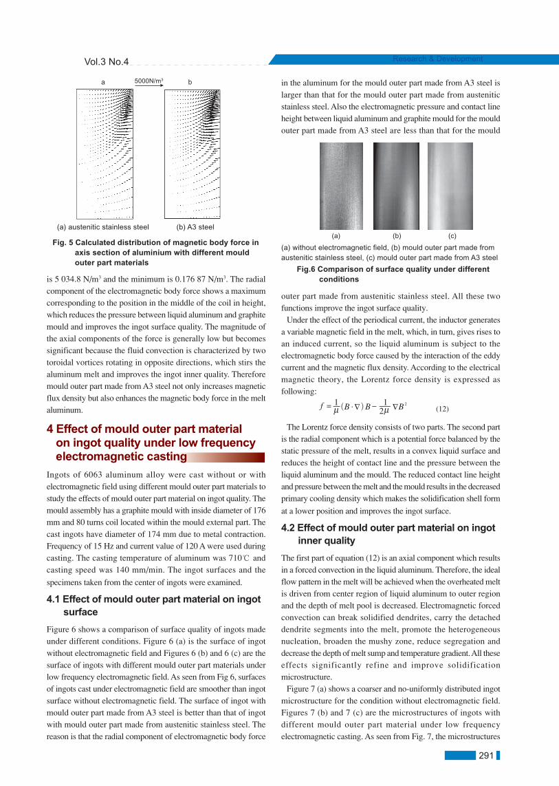
Electromagnetic force F is vector sum of FX, Fy and Fz. Its unit isNewton, represents the integral value of volume density ofelectromagnetic force in element. In fact, there are so manyelements of different size in a model, so the absolute value ofelectromagnetic force acted on different size element can not showthe actual effect. So the electromagnetic force must be transformedinto electromagnetic body force. Electromagnetic body force isthe key parameter to explain the essence of function of lowfrequency electromagnetic field. Its unit is Newton/m3.Electromagnetic body force distributions in the axial section arepresented in Fig.5.
As seen from Fig. 5, all the electromagnetic body forces in thealuminum are perpendicular to the surface and point to the innerof ingot, and attenuate rapidly towards center of ingot. When themould outer part is made from A3 steel, the maximum magneticbody force is 7 001.1 N/m3 on the surface of liquid aluminumand the minimum magnetic body force is 0.403 92 N/m3 in thecenter of liquid aluminum. When the mould outer part is madefrom austenitic stainless steel, the maximum magnetic flux density
(a) Austenitic stainless steel (b) A3 steel
A=0B=.00225C=.0045D=.00675E=.009F=.01125G=.0135H=.01575I=.018J=.02025K=.0225L=.02475M=.027N=.02925O=.0315P=.03375Q=.036R=.03825S=.0405T=.04275
Unit:Tside center side center
Unit:T
A=0B=.002842C=.005684D=.008526E=.011368F=.014211G=.017053H=.019895I=.022737J=.025579K=.028421L=.031263M=.034105N=.036947O=.039789P=.042632Q=.045474R=.048316S=.051158T=.054
a b
Vol.3 No.4 Research & Development
291
Fig. 5 Calculated distribution of magnetic body force in axis section of aluminium with different mould outer part materials
(a) austenitic stainless steel (b) A3 steel
is 5 034.8 N/m3 and the minimum is 0.176 87 N/m3. The radialcomponent of the electromagnetic body force shows a maximumcorresponding to the position in the middle of the coil in height,which reduces the pressure between liquid aluminum and graphitemould and improves the ingot surface quality. The magnitude ofthe axial components of the force is generally low but becomessignificant because the fluid convection is characterized by twotoroidal vortices rotating in opposite directions, which stirs thealuminum melt and improves the ingot inner quality. Thereforemould outer part made from A3 steel not only increases magneticflux density but also enhances the magnetic body force in the meltaluminum.
in the aluminum for the mould outer part made from A3 steel islarger than that for the mould outer part made from austeniticstainless steel. Also the electromagnetic pressure and contact lineheight between liquid aluminum and graphite mould for the mouldouter part made from A3 steel are less than that for the mould
4 Effect of mould outer part material on ingot quality under low frequency electromagnetic casting
Ingots of 6063 aluminum alloy were cast without or withelectromagnetic field using different mould outer part materials tostudy the effects of mould outer part material on ingot quality. Themould assembly has a graphite mould with inside diameter of 176mm and 80 turns coil located within the mould external part. Thecast ingots have diameter of 174 mm due to metal contraction.Frequency of 15 Hz and current value of 120 A were used duringcasting. The casting temperature of aluminum was 710 andcasting speed was 140 mm/min. The ingot surfaces and the
specimens taken from the center of ingots were examined.
4.1 Effect of mould outer part material on ingot surface
Figure 6 shows a comparison of surface quality of ingots madeunder different conditions. Figure 6 (a) is the surface of ingotwithout electromagnetic field and Figures 6 (b) and 6 (c) are thesurface of ingots with different mould outer part materials underlow frequency electromagnetic field. As seen from Fig 6, surfacesof ingots cast under electromagnetic field are smoother than ingotsurface without electromagnetic field. The surface of ingot withmould outer part made from A3 steel is better than that of ingotwith mould outer part made from austenitic stainless steel. Thereason is that the radial component of electromagnetic body force
The Lorentz force density consists of two parts. The second partis the radial component which is a potential force balanced by thestatic pressure of the melt, results in a convex liquid surface andreduces the height of contact line and the pressure between theliquid aluminum and the mould. The reduced contact line heightand pressure between the melt and the mould results in the decreasedprimary cooling density which makes the solidification shell form
at a lower position and improves the ingot surface.
4.2 Effect of mould outer part material on ingot inner quality
The first part of equation (12) is an axial component which resultsin a forced convection in the liquid aluminum. Therefore, the idealflow pattern in the melt will be achieved when the overheated meltis driven from center region of liquid aluminum to outer regionand the depth of melt pool is decreased. Electromagnetic forcedconvection can break solidified dendrites, carry the detacheddendrite segments into the melt, promote the heterogeneousnucleation, broaden the mushy zone, reduce segregation anddecrease the depth of melt sump and temperature gradient. All theseeffects significantly refine and improve solidificationmicrostructure.
Figure 7 (a) shows a coarser and no-uniformly distributed ingotmicrostructure for the condition without electromagnetic field.Figures 7 (b) and 7 (c) are the microstructures of ingots withdifferent mould outer part material under low frequencyelectromagnetic casting. As seen from Fig. 7, the microstructures
(12)
Fig.6 Comparison of surface quality under different conditions
(a) (b) (c)
(a) without electromagnetic field, (b) mould outer part made fromaustenitic stainless steel, (c) mould outer part made from A3 steel
outer part made from austenitic stainless steel. All these twofunctions improve the ingot surface quality.
Under the effect of the periodical current, the inductor generatesa variable magnetic field in the melt, which, in turn, gives rises toan induced current, so the liquid aluminum is subject to theelectromagnetic body force caused by the interaction of the eddycurrent and the magnetic flux density. According to the electricalmagnetic theory, the Lorentz force density is expressed asfollowing:
5000N/m3a b

CHINA FOUNDRY Nov. 2006
292
a cb
of ingot with LEFC are finer and more uniformly distributed thanthat without low frequency electromagnetic field. Themicrostructure of ingot with mould outer part made from A3 steelis finer and more uniformly distributed than that obtained withmould outer part made from austenitic stainless steel. This is becausethe axial component of electromagnetic body force in the aluminummelt with mould outer part made from A3 steel is larger, see Fig.4,and the forced convection and confined effect of Lorentz force arestronger than that with mould outer part made from austenitic steel.
5 Conclusions(1) Magnetic flux density and the electromagnetic body force in
the melt aluminum are more strengthened with the mould outerpart made from A3 steel than that with the mould outer part madefrom austenitic stainless steel.
(2) The surface of ingot cast under low-frequency electromagneticfield is smooth and has no exudation and cold shut defects, and theas-cast microstructure consists of fine, uniformly distributedequiaxed grains. The microstructure and surface quality of ingotwith mould outer part material made from A3 steel are better thanthat of ingot with mould outer part made from austenitic stainlesssteel.
AcknowledgmentsThe authors wish to express their appreciation to ANSYS Companyfor ANSYS software used in this work. The authors are grateful toKey laboratory of National Education Ministry for ElectromagneticProcessing of Materials, Northeastern University, for its experimentsupport
References
Fig.7 Comparison of microstructure in different conditions
(a) Without electromagnetic field (b) Mould outer part material with austenitic stainless steel (c) Mould outer part material with A3 steel
=VivÉs C. Effects of forced electromagnetic vibrations during thesolidification of aluminum alloys: Part 1. Solidification in thepresence of crossed alternating electric fields and stationarymagnetic fields. Metallurgical and Materials Transactions, 1996,27B: 445-455.
=VivÉs C. Effects of forced electromagnetic vibrations during thesolidification of aluminum Alloys: Part 2. Solidification in thepresence of linear variable and stationary magnetic fields.Metallurgical and Materials Transactions, 1996, 27B: 457-464.Kyung Shik OH, Yong Won Chang, Macrosegregation behaviorin continuously cast high carbon steel blooms and billets at thefinal stage of solidification in combination stirring. ISIJInternational, 1995, 35(7): 866-875.Anders Lehman, Gote Tallback, Ake Rullgard. Electromagneticbraking improves steel quality in continuous casting.
[1]
[2]
[3]
[4]
The project (G199906490501) was supported by the NationalKey Fundamental Research and Development Program ofChina
Continuous Casting, 1996(1): 4-10.Iwai K, Sassa K, Asai S. Theoretical analysis of the magneticfield of a cold crucible. Electromagnetic Forces andApplications, Amsterdam: Elsevier Science Publishers B.V.,1992, 263.ZHANG Bei-jiang, CUI Jian-zhong, LU Gui-min. Effect ofelectromagnetic frequency on microstructures of continuouscasting aluminum alloys. Journal of Materials Science andTechnology, 2002, 18(5): 1-3.ZHANG Bei-jiang, CUI Jian-zhong, LU Gui-min, et al. Effect ofelectromagnetic field on macrosegregation of continuouscasting 7075 aluminum alloy. Transactions of NonferrousMetals Society of China, 2002, 12(4): 158-161DONG Jie, CUI Jian-zhong, LIU Xiao-tao, et al. Super-highstrength 7A60 Al alloy by low- frequency electromagnetic cast(F- Intracrytalline solubility of alloy element and mechanicalproperty of billets with diameter of 0.2 m . The Chinese Journalof Nonferrous Metals, 2004, 14(1): 117-121 (in Chinese)DONG Jie, CUI Jian-zhong, LIU Xiao-tao, et al. Super-highstrength 7A60 Al alloy by low frequency electromagnetic cast(I) -as-cast structures of billets with diameter of 0.2 m. TheChinese Journal of Nonferrous Metals, 2003, 13 (6): 1494-1499.(in Chinese)ZHAO Zhi-hao, CUI Jian-zhong, DONG Jie, et al. Effect of low-frequency electromagnetic field on microstructure andmacrosegregation of horizontal direct chill aluminum alloy.Transactions of Nonferrous Metals Society of China, 2004, 14(6): 1095-1099.LI Jian-chao, MA Yong-lin, WANG Bao-feng, et al. Effects ofstructure materials of semi-continuous casting crystallizer foraluminum alloy under low-frequency electromagnetic field onmagnetic field. Special Casting & Nonferrous Alloy, 2005, 25(3): 133-135. (in Chinese)DONG Jie, CUI Jian-zhong, ZHAO Zhi-hao. IntracrytallineElement solubility and mechanical property of a new super-high strength and toughness Al alloy cast under low frequencyelectromagnetic field. Journal of Aeronautical Materials, 2003,23(1): 16-20. (in Chinese)ZHAO Zhi-hao, CUI Jian-zhong, ZUO YU-bo, et al. Effect oflow frequency electromagnetic field on the horizontal direct chillcasting 7075 aluminum alloy. Journal of Northeastern University(Natural Science), 2005, 26(1): 255-258. (in Chinese)
=VivÉs C. Electromagnetic refining of aluminum alloys by theCERM process: part . Working principle and metallurgicalresults. Metallurgical Transactions, 1989, 20B: 623-629.
=VivÉs C. Electromagnetic refining of aluminum alloys by theLFEC process: part . Specific practical problems and theirsolutions. Metallurgical Transactions, 1989, 20B: 631-643.
[5]
[6]
[7]
[8]
[9]
[10]
[11]
[12]
[13]
[14]
[15]

Vol.3 No.4 Research & Development
293
A s a structural material, magnesium alloys possess many
advantages when applied to automobile, aviation andspace-flight manufacture industries due to their excellentphysical and mechanical properties such as low density, highstrength/weight ratio, good ductility and castability [1-2].However, the high chemical reactivity or flammability ofmagnesium melt in atmosphere is a critical disadvantage,resulting in difficulty during liquid forming process. So, thedevelopment of casting process for magnesium alloys has beenslower than that for aluminum alloys, iron and steel.
Various die-casting processes are the major methods thatproduce 90% of magnesium alloy castings currently [3-5]. Onlya few of magnesium alloy parts are so far produced by sandcasting or low-pressure casting. Although die-casting processhas many advantages over other processes, such as highproductivity and high dimensional precision, the die castingparts produced by the process cannot be heat-treated tostrengthen because there is much micro-porosity under the skinof the castings. So the die casting parts usually are not used asload sustaining components.
Expendable Pattern Casting (EPC) is a process for formingnear net shape castings and can offer significant advantagesin economical savings over traditional green sand process, suchas remarkable cost reduction from casting cleaning andfinishing operations because of no binder in molding sand and
Principles and practice of lowpressure-expendable pattern castingprocess for magnesium alloys*LI Ji-qiang, FAN Zi-tian, WU He-bao, DONG Xuan-pu, ZHANG Da-fu,
HUANG Nai-yu(State Key Laboratory of Plastic Simulation and Die & Mold Technology, Huazhong University of Science and Technology, Wuhan
430074, P. R. China)
no parting line or no draft on castings, and relatively simpleshakeout or sand treatment system. Furthermore, it has moreflexibility in casting design, tighter dimensional tolerances andcomplex geometries, higher surface finishing. Therefore, it isregarded as “casting process for the 21st century”, and is
rapidly gaining popularity in foundry industry [6-7].
The experimental research primarily verifies that EPCprocess is suitable and favorable for producing magnesiumalloy castings. In addition to the characteristics of accurategeometric formation by EPC, there are still following uniquemerits[8-10]: (1) Within the pouring temperature range formagnesium alloys, EPS (expanded polystyrene) pattern isdecompounded into the mixture gas such as hydrocarbon (alkyland allyl), benzene, cinnamene, and the gas would protectmagnesium melt from oxidation and inflammation to a limitedextent. (2) The dry sand and vacuum are applied to molding,so the contact between magnesium alloy melt and moisture issignificantly reduced; as a result, the relevant casting defectscan be greatly overcome. (3) Compared with die castingprocess which is widely adopted presently, the investment costof EPC process is much lower, and the hot crack trend ofmagnesium alloy castings during solidification is reducedgreatly by good conceding capability of dry sand particles.(4) Mould filling is performed under lower flow velocity andlaminar flow manner, which gives opportunity to producecastings with no or less microporosity defect. Therefore themechanical properties of magnesium castings can be furtherimproved by heat-treatment. With above advantages, the EPCprocess for magnesium alloys is considered as a process of
possessing great superiority and wide application prospect.
Male, born in 1974, PhKD. Be engaged in the magnesium alloyand lost foam castingE-mail: [email protected]
Received date: 2006-03-08; Adopted date: 2006-08-28
*LI Ji-qiang
Abstract: A newly developed low-pressure expendable pattern casting (LP-EPC) process wasintroduced and its basic principles or effect factors were further analyzed. According to theoretical calculationand experimental results, the major casting parameters that are of great and critical importance on theprocess include pressure and flux of filling gas, decomposition characteristic and density of foam pattern,thickness and permeability of coating, pouring temperature, vacuum degree and their combination. Mostof casting defects can be effectively avoided by choosing the suitable parameters. The success achievedin pouring motor housing and exhaust manifold castings demonstrates the advantages of LP-EPC processin the production of high-complicated castings with high dimension accuracy.
Key word: magnesium alloys; vacuum sucking casting; low-pressure casting; expendable pattern castingCLC mumber: TG146.2/TG249.6 Document Code: A Article ID:1672-6421(2006)04-0293-04

CHINA FOUNDRY Nov. 2006
294
However, because magnesium alloys has low thermalcapability, poor flow and filling ability, gravity EPC processfor magnesium alloys is easily to encounter cold lap or misrundefects[10-12]. In order to solve these problems, a higher pouringtemperature (over 800) is usually required in the EPC ofmagnesium alloys, which not only needs more energyconsumption during melting but also increases the oxidationand gas absorption of magnesium melt. So it is not favorable tocast good magnesium alloy parts.
The Huazhong University of Science and Technology (HUST)has developed a new low- pressure expendable pattern casting(LP-EPC) process for magnesium and aluminum alloys, whichintegrates the counter-gravity low pressure into the EPC processto suit for forming of magnesium and aluminum melts [13-15].The new process is a desirable solution to produce magnesiumalloys with thin-wall, tighter dimensional tolerances andcomplex geometries. Due to its distinct characteristics of muchbetter mould filling ability under the condition of gas pressureassistance than that in the conventional EPC gravity process,the cold lap and misrun defects could be easily overcome andthe need of relying on excessive high pouring temperature
becomes less important or even unnecessary.
1 The principle of the LP-EPC process
The principle of LP-EPC process is shown in Fig.1 [15]. A well-compacted double layer molding box with foam pattern anddry sand is pushed into low pressure casting machine position,then magnesium melt is filled into mould and subsequentlysolidifies under controlled pressure and vacuum. The fillingvelocity of melt is affected by many factors including fillingtemperature, thermal degradation of foam patterns, gas pressurein crucible, the property of coating and the degree of vacuum.
The filling velocity (rate) of magnesium alloy melt isdetermined by the decomposition of EPS pattern, the gaspressure and flux controlled by valves, vacuum degree [16-18].According to the Bernoulli’s equation, the flow velocity v ofmelt can be expressed by the equation (1):
casting cross-sectional area A2, and the density of the molten
metal γ .
2 Influence factors
The stable filling of molten magnesium alloy into the mould isthe precondition of producing castings with high quality andno defects. The theoretical calculation and the experimentalresults indicated that the critical parameters for the castingprocess include the type of the foam pattern applied, itsdecomposition characteristic, density, thickness andpermeability of coating, pouring temperature, vacuum degree,the pressure and flux of filling gas, and the combination actionof the factors above [19].
The molten metal front losses more heat in the EPC processthan that in cavity mould casting process due to foam pyrolysis.The foam pyrolysis temperature and rate have a direct effect onboth mould filling velocity and casting integrity. The foam withlow pyrolysis temperature and high decomposing rate wouldneed less heat and conduce to filling mould. Contrarily, the foamwith high density would require more heat to decompose patternand lead to temperature being dropped greatly, and filling mouldvelocity is also decreased rapidly, so it is harmful to the fillingvelocity.
The coating thickness and permeability will mainly affectpyrolysis products to be transferred and escaped. Thick coatingwith low permeability will reduce the escaping rate of pyrolysisproducts, increase the flowing resistance of molten metal andextend mould filling time, which is harmful to the filling velocityof molten metal. Contrarily, thin coating with high permeabilityis beneficial to pyrolysis products escaping and metal filling.But the coating layer can not be too thin; otherwise, the castingsare prone to form metal penetration and scab defects.
Generally, the high pouring temperature would increase foampyrolysis rate and filling velocity. However, excessive pouringtemperature not only aggrandizes energy consumption but alsodeteriorates molten magnesium alloy oxidation and inspiration.Moreover, excessive pouring temperature will induce morepyrolysis products. The increasing temperature scope ofmagnesium alloys melt does not need to be too big. In fact, thepouring temperature that provides adequate heat energy iscapable to ensure both foam pyrolysis and full mould fillingcompleted.
The vacuum could improve the rigidity of the dry sand mouldof EPC to overcome mould expansion or collapse. Furthermore,vacuum sucking could also increase the differential pressure offilling, the escaped rate of the foam pyrolysis products and thefilling velocity of molten metal. But the ratio of metalpenetration and scab defects would increase as excessivevacuum degree is used. On the other hand, if the vacuum degreeis excessively high, the molten metal of flowing front wouldnot move smoothly and a lot of pore defects could be formed.Therefore, one of the critical points that we should concern isto select the appropriate “degree” of vacuum.
The gas pressure of filling mould is the main driving force inthe LP-EPC process. Generally, the high gas pressure with large
This mould filling velocity v is governed by pressure increasing
constant , foam decompounding rate , foam
pyrolysis coefficient kq , the crucible cross-sectional area A
1, the
Fig.1 The principle of the LP-EPC
T
P4
P3
P1
P0
C
B
A
D
tLift FillKeep
pressurize
Vacuum
Fillinggas
Vol.3 No.4 Research & Development
295
filling rate will lead to high molten metal filling velocity if foampyrolysis rate is sufficient. But when the foam pyrolysis rate islow (which may be resulted from lower pouring temperature),the molten metal filling velocity is mainly controlled by foampyrolysis, and the gas pressure and flux would becomesecondary.
In Fig.2, the isochronal lines of molten Mg-alloy flowing frontare shown at 0.5, 0.3 and 0.2 seconds interval after molten metalpassed through the ingate of experimental castings under variousfluxes. In these tests, L-shape and rectangle shape of flat foampattern with 5 mm thickness were prepared.
Figure 2 (a) shows the flowing model of molten Mg-alloyunder 1 m3/h flux of filling gas in the LP-EPC process. Itindicated that metal-foam interfacial boundaries exhibitedsmooth and convex shape once the flux of filling gas was lessthan 3 m3/h. Too low filling rate would lead to misrun defectsor incomplete filling.
As the flux of filling gas increased, the driving force for fillingmold also increased. When the flux was raised to 3 m3/h, themolten metal flowed faster and the slope of isochronal line
became bigger as shown in Fig.2 (b), and the filling time wasreduced greatly, so the misrun or other pyrolysis defect was noteasy to occurr on the plate castings.
Once the flux of filling gas was too high, for example 5 m3/h,the molten metal of flowing front would not move smoothly, asshown in Fig.2 (c), and a lot of pore defects would be found atthe inner and top end of castings. This is not surprising, becausewhen the filling velocity is too high and there is not sufficienttime for the liquid polymer to be removed through the coatinglayer, the pyrolysis products of the foam pattern would be pushedahead of the metal front, some pyrolysis products would alsobe engulfed in the molt metal to form pore defects.
The reasonable matching of the gas pressure in crucible andthe vacuum degree in sand box plays an important role in thethe LP-EPC filling. It was found that the cast parts had perfectexterior surface but many holes interior when we appliedvacuum sucking firstly, then to do mould filling. However, whenmould filling came before vacuum sucking, the cast parts wouldobtain both compact internal structure and perfect exterior
surface.
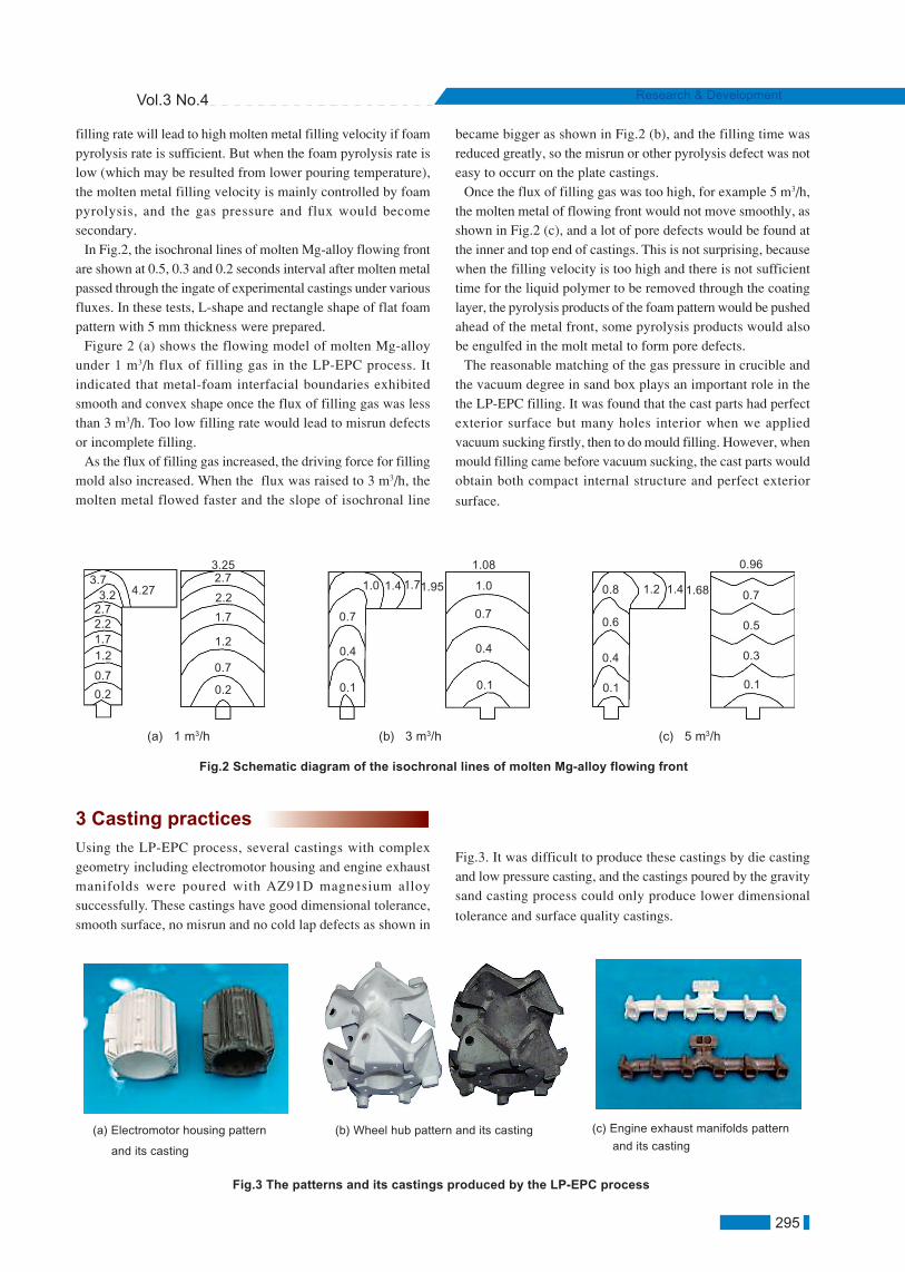
3 Casting practices
Using the LP-EPC process, several castings with complexgeometry including electromotor housing and engine exhaustmanifolds were poured with AZ91D magnesium alloysuccessfully. These castings have good dimensional tolerance,smooth surface, no misrun and no cold lap defects as shown in
Fig.3. It was difficult to produce these castings by die castingand low pressure casting, and the castings poured by the gravitysand casting process could only produce lower dimensional
tolerance and surface quality castings.
Fig.3 The patterns and its castings produced by the LP-EPC process
(a) Electromotor housing pattern
and its casting
(b) Wheel hub pattern and its casting (c) Engine exhaust manifolds pattern
and its casting
Fig.2 Schematic diagram of the isochronal lines of molten Mg-alloy flowing front
(a) 1 m3/h (b) 3 m3/h (c) 5 m3/h
0.2
0.7
1.21.72.22.73.2
3.74.27
3.252.7
2.2
1.7
1.2
0.7
0.2 0.1
0.4
0.7
1.0 1.4 1.71.95
1.08
1.0
0.7
0.4
0.1 0.1
0.4
0.6
0.8 1.2 1.4 1.68
0.96
0.7
0.5
0.3
0.1

CHINA FOUNDRY Nov. 2006
296
4 Application prospects
The new LP-EPC integrates the advantages of both counter-gravity low-pressure casting and EPC processes, offering severalcompetitive advantages. The new process is an excellent wayto produce magnesium alloy casting components with thin-walland complex geometric features due to their better mould fillingability than conventional EPC process. The potential defects ofthe castings produced under controlled atmosphere, such as coldlap and misrun in conventional EPC process, are easilyovercome or avoided without using excessive pouringtemperature. The authors believe that the new process will be aprecision casting method with great application prospects. Thepractice also shows that the LP-EPC process can produce thin-wall aluminum alloy castings with complex geometries and high
dimensional tolerances.
References
ZENG Xiao-qin, WANG Qu-dong, LU Yi-zhen. New evolutionon magnesium alloy application. Foundry (in Chinese), 1998,47(11): 39-43WANG Zhu-tang. Magnesium output of the world & magnesiumpurpose. Light Metal (in Chinese),1999, (6): 43-45WANG Zhi-qing. Development of die casting technology inoverseas. Foundry (in Chinese), 1997, 46(8): 48-51Stephen P. Vdvardy. NADCA research & development year2001 strategic plan and roadmap. Die Casting Engineer, 2000,58(1): 52-65Daniel L. Twarog. State of the die casting industry-1999. DieCasting Engineer, 2000, 58(1): 18-26HUANG Nai-yu, LUO Ji-rong. The expendable pattern castingtechnology facing to 21st century. Special Casting & NonferrousAlloys (in Chinese), 1998, 18(4): 37-40SUN Guo-xiong. Looking at the development trends of foundryindustry from the 64th world Foundry Conference. FoundryWorld Report (in Chinese), 2001, (1):15-16LIU Zi-li, WU Guo-hua, DING Wen-jiang, et al. Investigation onthe filling mould process of the expendable pattern casting formagnesium alloy. Foundry (in Chinese), 2002, 51(4): 209-213 LIU Zi-li, HU Jing-yu, DING Wen-jiang, et al. Evaluation of the
effect of vacuum on mold filling in the magnesium EPC process.Journal of Materials Processing Technology, 2002, 120(1): 94-100DONG Xuan-pu, FAN Zi-tian, HUANG Nai-yu, et al. Thepredominance and key of expendable pattern casting formagnesium alloy. Special Casting & Nonferrous Alloys (inChinese), 2003, 23 (4):30-36 AFS Magnesium Lost Foam Casting Committee (6-E). Genesisof a new process: magnesium lost foam casting. ModernCasting, 2003, 93(4): 26-28Marlatt M, Weiss D, Hryn J. Development in lost foam castingof magnesium. AFS Transaction, 2003, 111 (148): 1053-1060Osaka Giken, et al. Low pressure casting machine for metallicproducts, includes supply of non-oxidizing gas into furnace sothat molten metal is transferred into mold through stoker alongwith non-oxidizing gas. Patent No. JP3160842-B2, Applicationtime:1998-05-27, Public date 2001-04-25.DONG Xuan-pu, HUANG Nai-yu, WU Shu-sen, et al. Researchon new vacuum difference pressure foundry process. SpecialCasting & Nonferrous Alloys (in Chinese), 2001, 21, (4): 21-23FAN Zi-tian, DONG Xuan-pu, HUANG Nai-yu, et al. The Methodand Equipment of Expendable Pattern Casting under CounterGravity and Vacuum for Magnesium (or Aluminum) Alloy. ChinaInvention Patent (in Chinese), Patent Number: 02115638.7,Publicity Number: CN1382542A, Application time: 2002-03-26DONG Xiu-qi. Theory and Practice on Low Pressure &Difference Casting. China Machine Press (in Chinese), Beijing,2003HE Cun-xing. Hydraulic Pressure Transmission & Air PressureTransmission (The Second Edition, in Chinese). HuazhongUniversity of Science and Technology Press, Wuhan, 2000FAN Zi-tian, WU He-bao, ZHANG Da-fu, et al. A newexpendable pattern casting process with vacuum and lowpressure for magnesium alloy. China Mechanical Engineering(in Chinese), 2004, 15(16): 1493-1496.WU He-bao, FAN Zi-tian, HUANG Nai-yu, et al. Mold fillingcharacteristics of AZ91 Mg-alloy in the low-pressure EPCprocess. Journal of Material Engineering and Performance,2005, 14(1): 132-135.
[1]
[2]
[3]
[4]
[5]
[6]
[7]
[8]
[9]
This research work is sponsored and supported by the NationalNatural Science Foundation of China. The item number is50275058
[10]
[11]
[12]
[13]
[14]
[15]
[16]
[17]
[18]
[19]