appendix : uk grid services and activities e-science gap
TRANSCRIPT

Appendix : UK Grid Services and Activities e-Science Gap Analysis
30 June 2003
Geoffrey Fox, Indiana University David Walker, Cardiff University
Part V: Appendix (Section 14) UK Grid Services and Activities ............... 6
A.1. Summary of Services, Tools and Utilities ......................................................... 6 A.1.1 Tabular Classification of UK e-Science Services Tools and Utilities........... 6 A.1.2 Caveat to Table 1 ............................................................................................. 10
A.2. Contributions to Report..................................................................................... 11 A.2.1 Different Types of Grid and their Federation................................................ 11
A.2.1.1 Jini as an Infrastructure for Building Grids.............................................................. 11 A.2.1.1.1 Steven Newhouse (Imperial College) ........................................................................... 11 A.2.1.1.2 Mike Kirton (QinetiQ) .................................................................................................... 11
A.2.1.2 JXTA as an Infrastructure for Building Grids .......................................................... 11 A.2.1.2.1 Alistair Dunlop (Capital Radio Group)........................................................................... 11 A.2.1.2.2 Ian Taylor (Cardiff University) ....................................................................................... 12 A.2.1.2.3 Ian Sommerville (Lancaster University) ........................................................................ 12
A.2.1.3 Microsoft .NET ........................................................................................................ 13 A.2.1.3.1 Omer Rana (Cardiff University) .................................................................................... 13 A.2.1.3.2 Simon Cox (Southampton University)........................................................................... 13
A.2.1.4 Selected Snapshots of Current Activities................................................................ 14 A.2.1.4.1 Dynamic Configuration and Autonomic Computing (Ian Sommerville, Lancaster University).................................................................................................................................... 14 A.2.1.4.2 Grids and Virtual Private Networks (Matthew Dovey, Oxford e-Science Centre) .......... 14
A.2.2 e-Science Runtime and Hosting Environemnt.............................................. 15 A.2.2.1 Selected Snapshots and Current Activities............................................................. 15
A.2.2.1.1 Invocation Framework (Mike Surridge, IT Innovations)................................................. 15 A.2.2.1.2 ICENI (Steven Newhouse, Imperial College) ................................................................ 16 A.2.2.1.3 Messaging Infrastructure .............................................................................................. 16 A.2.2.1.4 Lightweight Middleware Technologies (Geoffrey Coulson, Lancaster University) ......... 17
A.2.3 Security Infrastructure .................................................................................... 18 A.2.3.1 Grid Security: Problems and Potential Solutions .................................................... 18
A.2.3.1.1 Requirements and Issues............................................................................................. 18 A.2.3.1.2 Possible Solutions ........................................................................................................ 19 A.2.3.1.3 Implementation Issues.................................................................................................. 19 A.2.3.1.4 Recommendations........................................................................................................ 20 A.2.3.1.5 Other Issues ................................................................................................................. 20
A.2.3.2 Possible Future Projects......................................................................................... 21 A.2.3.2.1 Harden VOMS from EDG (David Boyd, Rutherford-Appleton Laboratory) .................... 21
A.2.4 Workflow........................................................................................................... 21 A.2.4.1 Selected Snapshots of Current Activities................................................................ 21
A.2.4.1.1 Workflow at Southampton (Luc Moreau) ...................................................................... 21 A.2.4.1.2 Workflow at Newcastle (Paul Watson).......................................................................... 21 A.2.4.1.3 Workflow at Cardiff (Yan Huang) .................................................................................. 22 A.2.4.1.4 Workflow at IT Innovations (Mike Surridge) .................................................................. 22
A.2.4.2 Possible Future Projects......................................................................................... 23 A.2.4.2.1 Newcastle Workflow Engine (Paul Watson, North-East Regional e-Science Centre) ... 23
A.2.5 Notification Service ......................................................................................... 23 A.2.5.1 MyGrid and Wrapped JMS ..................................................................................... 23
A.2.5.1.1 Luc Moreau (Southampton University) ......................................................................... 23 A.2.5.1.2 Paul Watson (North-East Regional e-Science Centre) ................................................. 23
A.2.6 Metadata and Semantic Grid .......................................................................... 24 A.2.6.1 Selected Snapshots and Current Activities............................................................. 24

A.2.6.1.1 UDDI Evaluation (Omer Rana, Cardiff University) ........................................................ 24 A.2.6.1.2 Unicore and MDS (John Brooke and Donald Fellow, Manchester Computing) ............. 24 A.2.6.1.3 RGMA (David Boyd, Rutherford-Appleton Laboratory) ................................................. 26 A.2.6.1.4 Semantic Grid (Nigel Shadbolt, Southampton University)............................................. 26 A.2.6.1.5 SDT Semantic Discovery Toolkit (Luc Moreau, Southampton University)..................... 27 A.2.6.1.6 Metadata Management (Kerstin Kleese, Daresbury Laboratory) .................................. 27
(a) General Scientific Metadata Format ...................................................................................................... 27 (b) CCLRC Data Portal................................................................................................................................ 27
A.2.6.2 Possible Future Projects......................................................................................... 28 A.2.6.2.1 Semantic Grid Expectations (Nigel Shadbolt, Southampton University) ....................... 28 A.2.6.2.2 Intergrid service registry (Mike Surridge, IT Innovation)................................................ 28 A.2.6.2.3 Provenance Specification (Luc Moreau, Southampton University) ............................... 28 A.2.6.2.4 SRB Evaluation (Kerstin Kleese, Daresbury Laboratory).............................................. 28
A.2.7 Information Grid Technology including OGSA-DAI ..................................... 29 A.2.7.1 Current OGSA-DAI ................................................................................................. 29
A.2.7.1.1 Norman Paton (University of Manchester) .................................................................... 29 A.2.7.1.2 Dave Berry (National e-Science Centre)....................................................................... 30 A.2.7.1.3 Paul Watson (North-East Regional e-Science Centre) ................................................. 30
A.2.7.2 Selected Snapshots of Current Activities................................................................ 30 A.2.7.2.1 Environmental Grids (Bryan Lawrence, Rutherford-Appleton Laboratory) .................... 30 A.2.7.2.2 AstroGrid (Tony Linde, Leicester University) ................................................................ 31 A.2.7.2.3 The Storage Resource Broker (Kerstin Kleese, Daresbury Laboratory)........................ 32
A.2.7.3 Possible Future Projects......................................................................................... 34 A.2.7.3.1 Capital Radio (Alistair Dunlop, Capital radio Group) ..................................................... 34 A.2.7.3.2 Futures of OGSA-DAI (Norman Paton, University of Manchester)................................ 34 A.2.7.3.3 Environmental DataGrid (Bryan Lawrence, Rutherford-Appleton Laboratory) .............. 34 A.2.7.3.4 AstroGrid (Tony Linde, Leicester University) ................................................................ 35
A.2.8 Compute/File Grids: Scheduling Access to Mass Storage, Replica Management and Virtual Data .................................................................................. 36
A.2.8.1 Possible Future Projects......................................................................................... 36 A.2.8.1.1 Hardening of EDG Replica Technology (David Boyd, Rutherford-Appleton Laboratory)36 A.2.8.1.2 Hardening of EDG Compute Resource Broker (David Boyd, Rutherford-Appleton Laboratory) .................................................................................................................................. 36 A.2.8.1.3 Hardening of EDG Storage Element (David Boyd, Rutherford-Appleton Laboratory) ... 36
A.2.9 Other Technology Areas ................................................................................. 37 A.2.9.1 Selected Snapshots of Current Activities................................................................ 37
A.2.9.1.1 Grid Economies (Jon MacLaren, Manchester Computing) ........................................... 37 A.2.9.1.2 Improve Collaboration (Access Grid) Technology (Nigel Shadbolt, Southampton University).................................................................................................................................... 37 A.2.9.1.3 Computational Steering (John Brooke, Manchester Computing) .................................. 38 A.2.9.1.4 Data Access Services (Keith Haines, University of Reading) ....................................... 38 A.2.9.1.5 GridSite and SlashGrid (David Boyd, Rutherford Appleton Laboratory)........................ 39 A.2.9.1.6 Computational Markets (Steven Newhouse, Imperial College) ..................................... 39 A.2.9.1.7 Virtual Organisation Management (VOM) Portal (Steven Newhouse, Imperial College)40
A.2.9.2 Possible Future Projects......................................................................................... 40 A.2.9.2.1 Deployment of some appropriate amalgam of GridWeaver and LCFG for e-Science wide fabric management ...................................................................................................................... 40 A.2.9.2.2 Research topics at Edinburgh (Dave Berry, Edinburgh University)............................... 40
(a) System Configuration............................................................................................................................. 40 (b) Mobile Code........................................................................................................................................... 41 (c) Datamining and Visualization................................................................................................................ 41 (d) OGSA-DAI............................................................................................................................................. 41 (e) Data Curation.......................................................................................................................................... 41
A.2.9.2.3 Development of a Gridmake linked perhaps to LCFG (Jon Crowcroft, Cambridge University).................................................................................................................................... 42 A.2.9.2.4 Support for the Software Development (Jon Crowcroft, Cambridge University)............ 42
(a) “Grid Debug”.......................................................................................................................................... 42 (b) “Grid Log”.............................................................................................................................................. 43
A.2.9.2.5 Broad-based Visualisation Services (Ken Brodlie, Leeds University) ........................... 43 A.2.9.2.6 Visualisation and Computational Steering at Cardiff (Nick Avis, Cardiff University) ...... 43
(a) Visualization:.......................................................................................................................................... 44

(b) Computational Steering.......................................................................................................................... 44 (c) Use of National HPC resources ............................................................................................................. 44
A.2.9.2.7 Grid Visualisation Services at CCLRC (Lakshmi Sastry, Rutherford Appleton Laboratory).................................................................................................................................................... 45
(a) GAPtk visualisation server..................................................................................................................... 45 (b) Application programming interfaces ..................................................................................................... 45 (c) Applications............................................................................................................................................ 46
A.2.10 Portals and Problem-Solving Environments .............................................. 46 A.2.11 Grid-Network Interface .................................................................................. 46
A.2.11.1 Selected Snapshots of Current Activities in Monitoring and Management ........... 46 A.2.11.1.1 Peter Clarke (University College London)................................................................... 46 A.2.11.1.2 David Hutchison (Lancaster University) ...................................................................... 48
A.3. Domain-Specific and Project-Specific Services ............................................. 49 A.3.1 DAME services ................................................................................................. 49 A.3.2 Comb-e-Chem Services .................................................................................. 50 A.3.3 ICENI services .................................................................................................. 51
A.3.3.1 Execution Services ................................................................................................. 52 A.3.3.2 Scheduling Services ............................................................................................... 52 A.3.3.3 Software Services................................................................................................... 52 A.3.3.4 Application Services ............................................................................................... 52 A.3.3.5 Security Services .................................................................................................... 52 A.3.3.6 Fabric Services ....................................................................................................... 52 A.3.3.7 Data Services ......................................................................................................... 52 A.3.3.8 Economic Services ................................................................................................. 53 A.3.3.9 Collaboration Services............................................................................................ 53 A.3.3.10 Performance Services .......................................................................................... 53 A.3.3.11 ICENI Grid Middleware Framework ...................................................................... 53
A.3.4 Geodise Services ............................................................................................. 54 A.3.4.1 Generic Services .................................................................................................... 55
A.3.4.1.1 Geodise Computational Toolbox for Matlab (Matlab/Globus) ....................................... 55 A.3.4.1.2 Geodise Computational Toolbox for Jython.................................................................. 55 A.3.4.1.3 Computation Toolkit for Matlab (Matlab/ Condor) ......................................................... 55 A.3.4.1.4 Geodise Condor .NET Web Service ............................................................................. 55 A.3.4.1.5 XML Toolbox for Matlab................................................................................................ 56 A.3.4.1.6 Database Toolbox ........................................................................................................ 56 A.3.4.1.7 GUI Application for Workflow Construction and Life Cycle Management...................... 56 A.3.4.1.8 Short Message Service Used in Grid Computing Environment..................................... 57 A.3.4.1.9 Ontology Services ........................................................................................................ 57
A.3.4.2 Geodise-specific services ....................................................................................... 57 A.3.4.2.1 Optimisation Ontology .................................................................................................. 57 A.3.4.2.2 User Ontology .............................................................................................................. 57 A.3.4.2.3 Linux and Windows ProE.............................................................................................. 58 A.3.4.2.4 CFD Solvers (University of Oxford, Professor M Giles) ................................................ 58
A.4. XML Schema ....................................................................................................... 58 A.4.1 XML Schema for Service Workflow Language (SWFL)................................ 58
A.4.1.1 Current draft schema (Yan Huang, Cardiff University) ........................................... 58 A.5. Examples of Grids.............................................................................................. 61
A.5.1 Industrial Grids ................................................................................................ 62 A.5.1.1 DAME (Jim Austin, York University) ....................................................................... 62 A.5.1.2 Geodise (Simon Cox, Southampton University) ..................................................... 62
A.5.2 Military and Defense Grids (Mike Kirton, QinetiQ) ....................................... 63
A.6. Contributors and Interviewees ......................................................................... 63
A.7. Material from Pilot Projects............................................................................... 66 A.7.1 DAME Distributed Aircraft Maintenance Environment ................................ 66
A.7.1.1 Glossary.................................................................................................................. 66
A.7.1.2 Acronyms................................................................................................................ 69 A.7.1.3 Introduction ............................................................................................................. 70 A.7.1.4 Purpose and Scope ................................................................................................ 70 A.7.1.5 Service Architecture................................................................................................ 71
A.7.1.5.1 DAME Diagnostic Service Architecture......................................................................... 71 (a) Maintenance Engineer............................................................................................................................ 73 (b) Maintenance Analyst.............................................................................................................................. 73 (c) Domain Expert........................................................................................................................................ 73 (d) Collaborative Working Environment .................................................................................................... 73 (e) Workflow Subsystem ............................................................................................................................. 73 (f) DataAcqusitionSystem. .......................................................................................................................... 73 (g) DataStore-G............................................................................................................................................ 73 (h) DataTranslationService-G...................................................................................................................... 73 (i) GenericDataMiner-G. ............................................................................................................................. 73 (j) GenericDigitalSignalProcessor-G........................................................................................................... 73 (k) DataVisualiser-G.................................................................................................................................... 73 (l) CBRAnalyis-G ........................................................................................................................................ 73 (m) Database-G............................................................................................................................................ 73 (n) Model-G ................................................................................................................................................. 73
A.7.1.5.2 DAME Diagnostic Demonstration Service Architecture................................................. 74 (a) Collaborative Working Environment..................................................................................................... 76 (b) Workflow Subsystem............................................................................................................................. 76 (c) QUOTE / GSS. ....................................................................................................................................... 76 (d) EngineDataStore-G. ............................................................................................................................... 77 (e) AURA-G................................................................................................................................................. 77 (f) XTO-G .................................................................................................................................................... 77 (g) XTOOutputDataVisualiser-G ................................................................................................................ 77 (h) CBRAnalysis-G...................................................................................................................................... 77 (i) SDM-G .................................................................................................................................................... 78 (j) EngineModel-G....................................................................................................................................... 78
A.7.1.6 Main Use Cases and Example Workflows.............................................................. 79 A.7.1.6.1 Example Workflow for New DAME Use Case: Generate Diagnostic Workflow Script ... 80 A.7.1.6.2 Example Workflow for DAME Use Case 1: Perform Brief Diagnosis / Prognosis.......... 82 A.7.1.6.3 Example Workflow for DAME Use Case 2: Perform Detailed Diagnosis / Prognosis .... 84 A.7.1.6.4 Example Workflow for DAME Use Case 3: Perform Detailed Analysis ......................... 86 A.7.1.6.5 Example Workflow for DAME Use Case 4: Perform Cluster Search............................. 88 A.7.1.6.6 Example Workflow for New DAME Use Case: Develop New Detection Algorithm........ 91
A.7.1.7 Service Summaries................................................................................................. 93 A.7.1.7.1 Collaborative Working Environment Services ............................................................... 93 A.7.1.7.2 Workflow Subsystem Services ..................................................................................... 93 A.7.1.7.3 EngineDataStore-G Services........................................................................................ 94 A.7.1.7.4 AURA-G Services......................................................................................................... 94 A.7.1.7.5 XTO-G and XTOOutputDataVisualiser-G Services....................................................... 95 A.7.1.7.6 CBRAnalysis-G Services .............................................................................................. 96 A.7.1.7.7 SDM-G Services........................................................................................................... 97 A.7.1.7.8 EngineModel-G Services .............................................................................................. 97
A.7.1.8 References ............................................................................................................. 98 A.7.2 Discovery Net: e-Science Service Delivery Roadmap ................................. 99
A.7.2.1 Objectives ............................................................................................................... 99 A.7.2.2 Application Services: ............................................................................................ 100
A.7.2.2.1 Introduction................................................................................................................. 100 A.7.2.2.2 Overview of Application Service Operation Environment............................................ 101
A.7.2.3 Service Composition Environment........................................................................ 102 A.7.2.3.1 Workflow Construction, Storage and Execution.......................................................... 102 A.7.2.3.2 Workflow-based Service Registration and Deployment .............................................. 102
A.7.2.4 Support for Service Construction.......................................................................... 104 A.7.2.5 Discovery Net Deployment System ...................................................................... 105 A.7.2.6 DPML Discovery Process Markup Language ....................................................... 107
A.7.3 myGrid............................................................................................................. 108 A.7.3.1 Introduction ........................................................................................................... 108 A.7.3.2 Generic e-Science Components........................................................................... 108

A.7.3.2.1 Service Registry ......................................................................................................... 108 A.7.3.2.2 Semantic Service Discovery Service .......................................................................... 108 A.7.3.2.3 Service Ontology ........................................................................................................ 108 A.7.3.2.4 Service Description & Publication Tool ....................................................................... 109 A.7.3.2.5 Notification Service..................................................................................................... 109 A.7.3.2.6 Workflow Enactment Service...................................................................................... 109 A.7.3.2.7 Workflow Editor .......................................................................................................... 109 A.7.3.2.8 Information Repository ............................................................................................... 109 A.7.3.2.9 E-Science Gateway Service ....................................................................................... 109 A.7.3.2.10 E-Science Workbench .............................................................................................. 109 A.7.3.2.11 E-Science Web Portal .............................................................................................. 109 A.7.3.2.12 Distributed Query Processing Service ...................................................................... 109 A.7.3.2.13 E-Science Application Framework ............................................................................ 109
A.7.3.3 Bioinformatics-specific Components..................................................................... 110 A.7.3.3.1 Bioinformatics Ontology.............................................................................................. 110 A.7.3.3.2 SOAPLAB................................................................................................................... 110
A.7.3.4 Miscellaneous Components.................................................................................. 110 A.7.3.4.1 AntMerge: build-file construction tool.......................................................................... 110
A.7.4 The eDIKT Project and OGSA-DAI ............................................................... 111 A.7.4.1 OGSA-DAI vs eDIKT::eldas.................................................................................. 111 A.7.4.2 Foundations for eDIKT applications...................................................................... 111
Part V: Appendix (Section 14) UK Grid Services and Activities
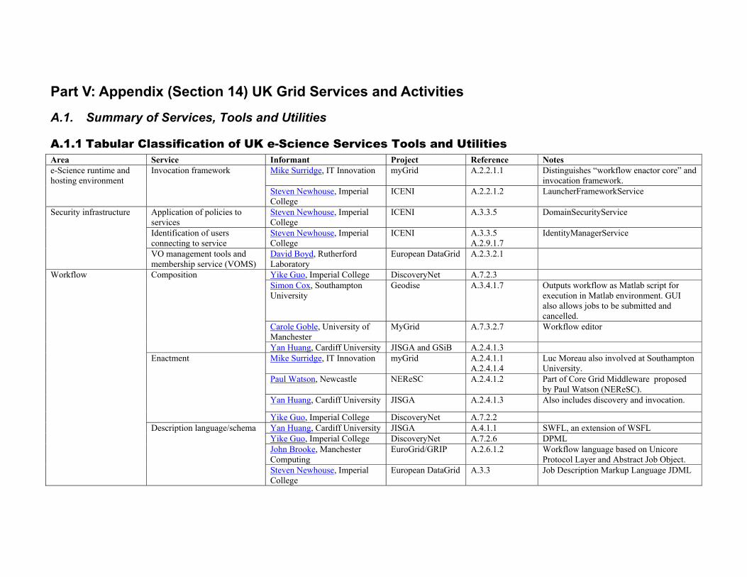
A.1. Summary of Services, Tools and Utilities
A.1.1 Tabular Classification of UK e-Science Services Tools and Utilities Area Service Informant Project Reference Notes
Mike Surridge, IT Innovation myGrid A.2.2.1.1 Distinguishes “workflow enactor core” and invocation framework.
e-Science runtime and hosting environment
Invocation framework
Steven Newhouse, Imperial College
ICENI A.2.2.1.2 LauncherFrameworkService
Application of policies to services
Steven Newhouse, Imperial College
ICENI A.3.3.5 DomainSecurityService
Identification of users connecting to service
Steven Newhouse, Imperial College
ICENI A.3.3.5 A.2.9.1.7
IdentityManagerService
Security infrastructure
VO management tools and membership service (VOMS)
David Boyd, Rutherford Laboratory
European DataGrid A.2.3.2.1
Yike Guo, Imperial College DiscoveryNet A.7.2.3 Simon Cox, Southampton University
Geodise A.3.4.1.7 Outputs workflow as Matlab script for execution in Matlab environment. GUI also allows jobs to be submitted and cancelled.
Carole Goble, University of Manchester
MyGrid A.7.3.2.7 Workflow editor
Composition
Yan Huang, Cardiff University JISGA and GSiB A.2.4.1.3 Mike Surridge, IT Innovation myGrid A.2.4.1.1
A.2.4.1.4 Luc Moreau also involved at Southampton University.
Paul Watson, Newcastle NEReSC A.2.4.1.2 Part of Core Grid Middleware proposed by Paul Watson (NEReSC).
Yan Huang, Cardiff University JISGA A.2.4.1.3 Also includes discovery and invocation.
Enactment
Yike Guo, Imperial College DiscoveryNet A.7.2.2 Yan Huang, Cardiff University JISGA A.4.1.1 SWFL, an extension of WSFL Yike Guo, Imperial College DiscoveryNet A.7.2.6 DPML John Brooke, Manchester Computing
EuroGrid/GRIP A.2.6.1.2 Workflow language based on Unicore Protocol Layer and Abstract Job Object.
Workflow
Description language/schema
Steven Newhouse, Imperial College
European DataGrid A.3.3 Job Description Markup Language JDML
Area Service Informant Project Reference Notes Representation conversion Yan Huang, Cardiff University JISGA and GSiB A.2.4.1.3 Converts between workflow diagram,
SWFL description, and Java harness code. Workflow (continued)
Case-Base Reasoning Workflow Advisor
Jim Austin, University of York DAME A.3.1 Decides which of several diagnostic workflows to use in given situation.
Luc Moreau, Southampton University
myGrid A.2.5.1.1 Wrapped JMS Notification
Paul Watson, Newcastle NEReSC A.2.5.1.2 Part of Core Grid Middleware proposed by Paul Watson (NEReSC).
Notification service
Geodise Short Message Service (SMS)
Simon Cox, Southampton University
Geodise A.3.4.1.8 Sends text message to mobile phone about job status or results from execution environment.
Provenance Luc Moreau, Southampton University
myGrid A.2.6.2.3
Ontology support for services, and bioinformatics ontology
Carole Goble, University of Manchester
myGrid A.7.3 OWL ontology to describe services
Ontology services Simon Cox, Southampton University
Geodise A.3.4.1.9 Used to inform workflow construction.
General Scientific Metadata Schema
Kerstin Kleese, Daresbury Laboratory
CLRC DataPortal A.2.6.1.6
Resource brokering John Brooke, Manchester Computing
EuroGrid/GRIP A.2.6.1.2 GRIP broker based on Unicore
Luc Moreau, Southampton University
myGrid A.2.6.1.5 Service Directory Toolkit
Steven Newhouse, Imperial College
ICENI A.3.3 ComponentRepositoryService
Yike Guo, Imperial College DiscoveryNet A.7.2.3.2
Service deployment and publication
Carole Goble, University of Manchester
myGrid A.7.3 Includes a Service Registry that federates multiple registries in a VO, and a Service Description and Publication Tool for semantically annotating services. The registry also supports semantic service discovery based on OWL.
Gateway service to VO Carole Goble, University of Manchester
myGrid A.7.3 e-Science Gateway Service gives API and point of access to myGrid resources in VO
Grid monitoring David Boyd, Rutherford Laboratory
European DataGrid A.2.6.1.3 Relational Grid Monitoring Architecture (R-GMA). A service meta-data look-up service
Metadata and Semantic Grid
Service discovery Steven Newhouse, Imperial College
ICENI A.3.3 ApplicationMappingService

Area Service Informant Project Reference Notes Metadata and Semantic Grid (continued)
Scheduling service Steven Newhouse, Imperial College
ICENI A.3.3.2 SchedulingFrameworkService
Storage Resource Broker (SRB)
Kerstin Kleese, Daresbury Laboratory
Collaboration between DL and SDSC
A.2.6.2.4 and A.2.7.2.3
Gives uniform interface to access to heterogeneous distributed data sources. Divided into Core SRB and MCAT.
Norman Paton, University of Manchester
OGSA-DAI A.2.7.1.1 A.2.7.1.2 A.2.9.2.2(d)
Registration, creation, and use of Grid Data Services. See also Dave Berry
OGSA-DAI services
Paul Watson, Newcastle NEReSC A.2.7.1.3 Part of Core Grid Middleware proposed by Paul Watson (NEReSC).
Carole Goble, University of Manchester
MyGrid A.7.3.2.12 Based on OGSA-DAI, and used to federate myGrid information repositories in VO
Distributed query processing service
Paul Watson, Newcastle NEReSC A.2.7.1.3 Part of Core Grid Middleawre proposed by Paul Watson (NEReSC).
Advanced Uncertain Reasoning Architecture (AURA-G)
Jim Austin, University of York DAME A.3.1 Enables fast searches of very large databases.
Data staging service Mike Surridge, IT Innovation Comb-e-Chem A.3.2 Based on Grid Resources for Industrial Applications (GRIA) system.
MySpace directory service Tony Linde, Leicester University
AstroGrid A.2.7.2.2 Virtual directory service of data items located anywhere on Grid.
Storage service Simon Cox, Southampton University
Geodise A.3.4.1.6 Storage and retrieval of files.
Metadata storage and query service
Simon Cox, Southampton University
Geodise A.3.4.1.6 Allows metadata to be associated with files and used in queries.
Authorization service Simon Cox, Southampton University
Geodise A.3.4.1.6 Grants access rights based on authorization database.
Information Grid technologies
Location service Simon Cox, Southampton University
Geodise A.3.4.1.6 Locates files by mapping handle to location.
Grid interface to mass storage David Boyd, Rutherford Laboratory
European DataGrid A.2.8.1.3 Storage Element gives access to data on disk and tape over WAN with Control Interface, Data Interface, and Command Line Interface.
Replica location service and metadata catalogue Replica optimisation service Replica storage handler
David Boyd, Rutherford Laboratory
European DataGrid A.2.8.1.1
Compute/File Grids
Resource broker David Boyd, Rutherford Laboratory
European DataGrid A.2.8.1.2 RB work being done mainly in Italy, but UK involved in debugging, testing, and quality assurance.

Area Service Informant Project Reference Notes
Grid Access Data Service (GADS)
Keith Haines, Reading University
GODIVA A.2.9.1.4 Gives access to spatial data sets through web portal.
John Brooke, Manchester Computing
RealityGrid A.2.9.1.3 A.2.9.2.5 A.2.9.2.6
Steering Grid Service migrating from Unicore to GT2 and GT3.
Ken Brodlie, Leeds University gViz A.2.9.2.5
Computational steering and visualisation
Nick Avis, Cardiff University A.2.9.2.6 Interactive supercomputing Grid-debug, Grid-log, and Grid-make
Jon Crowcroft, University of Cambridge
A.2.9.2.3 A.2.9.2.4
Some proposed systems tools for Grid environments
GridSite and SlashGrid David Boyd, Rutherford Laboratory
GridPP and European DataGrid
A.2.9.1.5 GridSite is for Web site maintenance, and SlashGrid is for adding file systems to Unix systems and to give access to remote resources using Grid protocols.
Logging facility Tony Linde, Leicester University
AstroGrid A.2.7.2.2 Log events with custom identifiers.
Geodise Matlab Toolbox Simon Cox, Southampton University
Geodise A.3.4.1.1 Globus job submission and control, file transfer, and proxy certificate management from within a Matlab environment.
Geodise Jython Toolbox Simon Cox, Southampton University
Geodise A.3.4.1.2 Globus job submission and control, file transfer, and proxy certificate management from within Jython.
Matlab/Condor Toolkit Simon Cox, Southampton University
Geodise A.3.4.1.3 Computation toolkit linking Matlab to Condor/
Geodise Condor/.NET Web service
Simon Cox, Southampton University
Geodise A.3.4.1.4 .NET Web service enabled interface to the Condor system
XML Toolbox for Matlab Simon Cox, Southampton University
Geodise A.3.4.1.5 Converts from Matlab format to XML, and vice versa.
Other technology areas
Case-Based Reasoning Analysis service
Jim Austin, University of York DAME A.3.1 A.7.1
Uses CBR to suggest most likely diagnosis.
Interaction with services and metadata
Carole Goble, University of Manchester
myGrid A.7.3 e-Science Workbench based on NetBeans. e-Science Portal is alternative with smaller footprint for handheld devices.
Portals and Problem-Solving Environments
Searching and accessing metadata
Kerstin Kleese, Daresbury Laboratory
CLRC DataPortal A.2.6.1.6 Parallel search and exploration of distributed heterogeneous metadata catalogues.
Domain specific services Comb-e-Chem specific services
Mike Surridge, IT Innovation Comb-e-Chem A.3.2 Virtual Network Compputing service - allows user to simultaneously view GUI used lab-side by experimenter.
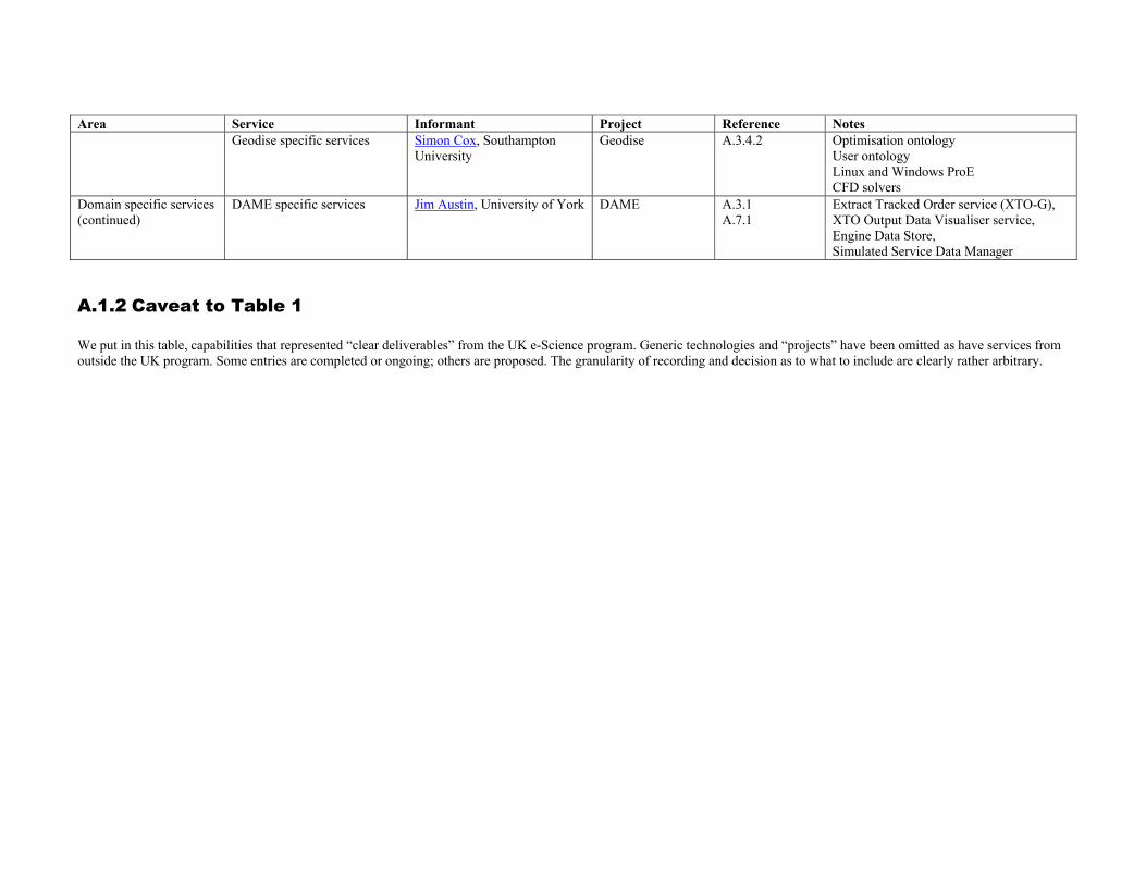
Area Service Informant Project Reference Notes Geodise specific services Simon Cox, Southampton
University Geodise A.3.4.2 Optimisation ontology
User ontology Linux and Windows ProE CFD solvers
Domain specific services (continued)
DAME specific services Jim Austin, University of York DAME A.3.1 A.7.1
Extract Tracked Order service (XTO-G), XTO Output Data Visualiser service, Engine Data Store, Simulated Service Data Manager
A.1.2 Caveat to Table 1 We put in this table, capabilities that represented “clear deliverables” from the UK e-Science program. Generic technologies and “projects” have been omitted as have services from outside the UK program. Some entries are completed or ongoing; others are proposed. The granularity of recording and decision as to what to include are clearly rather arbitrary.
A.2. Contributions to Report
A.2.1 Different Types of Grid and their Federation A.2.1.1 Jini as an Infrastructure for Building Grids A.2.1.1.1 Steven Newhouse (Imperial College) ICENI has been developed over the last three years by what is now the Grid Middleware group within the London e-Science Centre. An initial prototype was demonstrated at the first UK e-Science Programme’s All Hands Meeting in September 2002 and at SuperComputing 2002 in November. This prototype was built using Java as the primary programming language and Jini as the underlying service oriented infrastructure. Jini not only provides easy integration with the Java language, but it also provides several desirable features for building a grid middleware. Fundamental to Jini, through its use of Java’s Remote Method Invocation (RMI), is the declaration of a service interface. This interface is registered into Jini’s Lookup Server with a ‘lease’ declaring the duration of the service’s availability. Clients search the look up server for service instances based on the service type. The use of leases within Jini is recognition of the transient nature of services within a distributed (grid) environment. The event notification architecture within Jini allows any service failure to be trapped and handled. To use Jini within ICENI it was necessary to incorporate methods to hold and search additional service meta-data than that provided in the standard Jini model. References: [ICENI] [Jini]
A.2.1.1.2 Mike Kirton (QinetiQ) Jini technology from Sun Microsystems provides a distributed software environment that facilitates the dynamic inter-operation of devices, services and applications on a network (http://www.jini.org). The DARPA Control of Agent-Based Systems programme (http://coabs.globalinfotek.com) used Jini as the basis for the development of the CoABS Grid, which had the aim of demonstrating the run-time integration of heterogeneous agent, object and legacy software components into military applications. The CoABS Grid makes use of two important components of Jini:
• look-up services, which are used to register and discover agents and other services; multiple look-up services can be run for robustness and scalability;
• entries, which are placed in look-up services by agents to advertise their capabilities. The CoABS Grid uses the underlying Jini infrastructure to provide a message-passing service for agents; a logging service to log both message traffic and other information; a security service to provide authentication, encryption and secure communication; and event notification when agents register, de-register, or change their advertised attributes. In demonstrations of the CoABS Coalition Agents Experiment (http://www.aiai.ed.ac.uk/project/coax) up to fifteen laptops were connected via the CoABS Grid with the system incorporating in the region of seventy heterogeneous agent systems and agent-wrapped legacy military systems. References: [Jini] [CoaxGrid] [CoABS-A] [CoABS-B]
A.2.1.2 JXTA as an Infrastructure for Building Grids A.2.1.2.1 Alistair Dunlop (Capital Radio Group) JXTA is a collaborative research project that is defining a set of protocols to enable P2P computing. Attempting to define standards in P2P computing is acknowledgement of the proliferation of different systems that now fall into this area. In posing the question as to whether JXTA is an appropriate infrastructure for building Grids, we are effectively asking two related questions. Firstly, is P2P an appropriate paradigm for Grid construction, and secondly, even if this is the case, whether JXTA is the most appropriate P2P infrastructure for this task. In answer to the first question, all popular Grids are currently based on P2P technology. Examples of this include compute Grids such as those using Entropia technology and data Grids such as Kazaa, Grokster and Morpheus which were all initially built on Fasttrack’s P2P protocol suite. The important part to realise here is that Grid computing in these forms has already entered the mass market to basic web and Internet users. These systems are simple to set up and new Grids are emerging daily. The existence of both compute and data grids using P2P technology gives weight to the argument that P2P methods can be used effectively to build certain Grids. The second question is whether JXTA is an appropriate platform for P2P Grid construction. Supporting JXTA is the fact that this is the only standards attempt to formalise P2P computing. There are
also numerous reference implementations for JXTA with work in developing reference implementations for most popular languages. JXTA also has many developers (going by the number of downloads) and there are many products being developed using this platform. In this sense it is inevitable that many Grids based on JXTA will appear over time. They may even be the next killer application. JXTA is however, not all things to all people. Many of the semantics of Globus Grid computing are absent from JXTA, or quite different in JXTA. This does not invalidate either approach. Users will ultimately dictate what services are required from Grids -many users are already experimenting with P2P in the form of JXTA and are finding success. This is certainly not a technology that can be ignored. References: [JXTA] [CapitalRadio]
A.2.1.2.2 Ian Taylor (Cardiff University) The current JXTA reference implementation of the JXTA protocols is written in Java. Other implementations are available but generally have limited functionality e.g. the JXTA C version currently only implements edge-peer functionality and cannot act as relays or rendezvous nodes. The Java implementation generally has been tested within a limited application domain and, in our opinion not advanced enough to build production P2P Grids. For example, discovery in JXTA works reasonably for a limited number of advertisements i.e. if you discovered peers by using pipes and each peer had just one input and one output pipe then for a limited number of peers, the current implementation works well. However, if you attempt to create more pipes per peer or if you attempt to advertise and discover pipes from a large number of peers e.g. >100, then the process is very slow and prone to failure. This initial setting up of the network is fundamental to creating scalable applications and is not stable in the current version.
Giving these noted problems, JXTA does still remain a viable option for building Grids if such problems with the implementation are resolved. JXTA also address several issues not considered currently within the Grid community. One significant is the nature of a JXTA peer. A JXTA peer can be a client, a server, a relay or a lookup server (i.e. a rendezvous node). In Web Services, the lookup server is located on a third party machine e.g. using UDDI or similar. Furthermore, JXTA peers can be dynamically organized as the network grows in a number of ways and employ the advantages of small world networks, where a large number of nodes can be connected in such a way as to minimize the number of hops a packet takes in order to traverse the network.
Organization of JXTA peers is independent to the underlying physical devices and connectivity and arranged within a virtual network overlay. Peers are not required to have direct point-to-point network connections and can spontaneously discover each other on the network to form transient or persistent relationships called peer groups that define specific behaviour for its peers. Current web services and OGSA specifications do not address these issues to a comprehensive degree. Much can be learned from the P2P research in this respect. OGSA, for example, is presently more concerned with the secure creation or deployment of services and their organization with respect to their transient nature. Another key feature of JXTA is the ability to traverse NAT translation systems and firewalls. In contrast, JXTA does not address how a service is created, it simply assumes such services already exist (as they do with file-sharing software for example). The dynamic creation of JXTA services would not be possible without the aid of an external toolkit, such as Globus. References: [JXTA] Triana-A] Triana-B]
A.2.1.2.3 Ian Sommerville (Lancaster University) JXTA is a communications middleware for peer-to-peer application development and is a set of open, generalised, peer-to-peer protocols that allows any connected device to communicate, collaborate and share resources on an ad-hoc, pervasive, peer-to-peer virtual network. The JXTA protocols define the basic building blocks to allow development of peer-to-peer applications and networks; -
Peer Discovery Protocol - Enables peers to discover peer services on the network Peer Resolver Protocol - Allows peers to send and process generic requests Rendezvous Protocol—Handles the details of propagating messages between peers Peer Information Protocol—Provides peers with a way to obtain status information from other peers on the network Pipe Binding Protocol—Provides a mechanism to bind a virtual communication channel to a peer endpoint Endpoint Routing Protocol—Provides a set of messages used to enable message routing from a source peer to a
destination peer JXTA is still in its early stages of development, and as such there are problems that can be encountered when using the technology. Connectivity is a main issue, every time a connection is made to the JXTA virtual network a peer typically sees a different topology, and more importantly, perhaps only a subset of the entire network (network partitioning). This means that some peer, known to some connecting peer, may or may not be accessible even if both exist upon the same network. Discovery of other peers and services can take time, and can also generate a lot of network traffic; this is due to discovery messages being propagated throughout the network. JXTA maintains a cache upon each peer, this

holds addressing information about other peers and any other critical information, the way JXTA handles this cache appears to be inefficient, and we have experienced extreme amounts of disk thrashing as the cache is periodically maintained/updated. JXTA is very Java specific. It operates at a higher level of abstraction than the current OGSA proposals and, in this respect, could have some advantages for use as a basis for grid construction. The basic application assumptions reflected in the Globus middleware where an application and/or its data are downloaded to remote computers for execution can easily be supported in JXTA for Java applications. However, for applications in other languages some kind of wrapping would probably be necessary. The latest versions of JXTA are stable and usable and a short-term research project to investigate its use for building grids would be justified. References: [JXTA]
A.2.1.3 Microsoft .NET A.2.1.3.1 Omer Rana (Cardiff University) The .NET platform provides a useful way to construct Grid Systems that make use of the emerging interest in Web services. Various tools are available for reducing the complexity of implementing a Web services, and providing support for messaging between such services. Visual Studio .NET provides a development environment for writing such services in C# and J# (Microsoft’s version of Java), for instance. The importance of such tools is essential to enable a wider adoption and usage of Web services-oriented Grid software. The .NET platforms also support a number of additional features that could be useful to construct Grid systems, particularly for enabling a number of different platforms to interact. The “Common Language Runtime” (CLR) in .NET provides an execution environment that can be ported to a number of different machine architectures, and supports the execution of programs written in a variety of different languages. The CLR adopts a similar approach to the Java Virtual Machine, for enabling code developed on one machine to be ported (without re-compilation) to another. The .NET platform also provides a Just-In-Time (JIT) compiler that allows dynamic performance improvements during the execution of a program, and is facilitated in this by the CLR. Microsoft is also aiming to make a version of the CLR open-source, to enable community input into this activity. References: [ECMA.NET] [Mono.NET]
A.2.1.3.2 Simon Cox (Southampton University) Microsoft .NET is an XML Web services platform that provides comprehensive support for major open-standard Web services technologies. It enables users to create new Web services, or transform existing programs to Web services in a relatively simple manner and provides comprehensive cross-language support. Grid services that provide resources such as compute, data and application, especially those available from Windows platform, can be constructed based on the .NET platform and be accessed transparently. The latest enhancement package to .NET also provides the much desired Grid features such as security management and improved performance on data transmission. In addition, together with Microsoft Internet Information Server (IIS) and the Active Directory technology, .NET can be used to create the hosting environment for transient Web services proposed in OGSA. It has proved straightforward to construct and integrate together Windows based web-services constructed using .NET and those from a variety of Linux web-service construction tools. This is occasionally necessary where codes only run on Windows, and is desirable where there is a requirement to improve resource utilisation on idle (Windows-based) desk-top PCs. Particular examples of use of .NET include providing a .NET interface to Condor and wrapping a number of database services using .NET (Geodise Project). In August, 2000, Microsoft Corporation, Hewlett-Packard and Intel Corporation co-sponsored the submission of specifications for the Common Language Infrastructure (CLI) and C# programming language to the international standardization organization ECMA- this work is active and ongoing (http://www.dotnetexperts.com/ecma/). Furthermore, the Mono project (http://www.go-mono.com/) is bringing the .NET platform to Linux. Early demonstrators of this in action (at University of Southampton) include construction and deployment of peer-to-peer systems build on Windows and deployed on Linux. .NET is thus able to provide both cross-language and cross-operating system support. References: [ECMA.NET] [Mono.NET]

A.2.1.4 Selected Snapshots of Current Activities A.2.1.4.1 Dynamic Configuration and Autonomic Computing (Ian Sommerville, Lancaster University) Dynamic re-configuration is the process of changing an executing system without stopping execution and with minimal re-computation after the system has been reconfigured. It can take two forms: 1. Replacing executing modules in the system with different modules. This is required for non-stop systems where the
software must be upgraded without taking the system out of service. 2. Changing the platform nodes on which modules of the system are executing. This latter form if dynamic re-configuration is the most relevant for the Grid, at least in the foreseeable future. There are two forms of this dynamic reconfiguration that are relevant for the grid. 1. Application restructuring to take advantage of additional execution platforms that may become available. For
example, if a parallel application can run on any number of nodes, then the number of nodes actually used may change during the execution depending on availability, cost, etc. This is required to realise the far-sighted vision of the Grid.
2. Load re-allocation where executing jobs are moved in execution from one node to another. This might be because a node has failed or shows signs of failure, because a cheaper resource has become available or as part of an overall load balancing strategy.
Load re-allocation is currently the task of system managers and usually involves stopping a job before moving it to another node. If we are to develop an autonomic computing system, we need to automate this process and allow the system itself to allocate and re-allocate jobs to nodes. The problems of dynamic re-configuration are non-trivial and current grid middleware does not provide any support whatsoever for this process. The most promising technology to apply here is probably reflective middleware where the middleware can have awareness of its own actions. There is then the possibility of developing strategies for dynamic re-allocation. It is unlikely that current techniques of dynamic re-configuration are applicable without change to the Grid; reflective middleware is still a research topic. Therefore, my view on this is that further research into dynamic re-configuration and the Grid is required before the middleware ‘gap’ can be filled.
A.2.1.4.2 Grids and Virtual Private Networks (Matthew Dovey, Oxford e-Science Centre) The UK e-Science GRID is one of the first GRID's to attempt to deploy Globus outside of a private network. A number of security issues have emerged in the design of GT2 when deployed over large public networks such as the internet. Essentially the problems reside in two areas:
i) the use of port mapping - whereby a well known port is used to negotiated a transient high level port used for the rest of the client/server session
ii) a requirement for a client to have a fixed IP Address for notification services In practice, many institutions make use of technologies such as port blocking routers, firewalls, NAT (Natural Address Translation) and DHCP (Dynamic Host Configuration Protocol) to improve the security and manageability of their networks. GT2 is not compatible with these technologies because IP addresses are allocated dynamically, are routed through a “proxy” public IP addresses or the particular ports used by GT2 are blocked. One solution would be to use VPNs (Virtual Private Networks) to create the private network environment that Globus is designed for. VPN’s use tunneling technologies so that clients behave as if on a single private network, even though traffic may pass over public internets. There are currently two VPN technologies - PPTP and L2TP which tunnel the network traffic in different ways. L2TP is the more secure and it can use IPSec to encrypt the data, and hence can make use of certificate based PKI. There are currently two VPN technologies – PPTP (Point to Point Tunneling Protocol) and L2TP (Layer 2 Tunneling Protocol) which tunnel the network traffic in different ways. L2TP is the more secure and it can use IPSec to encrypt the data, and hence can make use of certificate based PKI (Public Key Infrastructure). VPNs can also provide a solution to the fixed IP Address issue. Although the client machine may have a dynamically assumed or NAT IP Address, the VPN server could allocate a static (virtual) IP Address. If the VPN is based on L2TP/IPSec then this could be allocated by using a GRID certificate to authorise and authenticate the end user. There are however a number of issues with VPNs:
i) firewalls may block the ports or protocols required by PPTP or L2TP. However, the required policy for the firewall management of participating institutions is far simpler (as only the ports and protocols for the VPN will be required to be open)
ii) vendor interoperability is still an issue, for instance in Oxford we have not managed to use the Microsoft VPN client to attach to our Cisco VPN server. This has potential impact if the GRID is to support heterogeneous platforms.
iii) availability of VPN clients on some platforms may be problematic - especially if the GRID is to emcompass mobile devices
iv) Access to local resources - by default a VPN client will route all requests to IP Addresses outside the local subnet over the VPN. This may cause problems if the user wishes to access resources on a local firewall protected WAN (Wide Area Network). If the resource is outside the immediate subnet but within the WAN firewall the VPN client will attempt to route the request over the VPN and outside the firewall, hence the request maybe blocked by the WAN firewall. It is theoretically possible to manually configure the client routing tables to cope with this, but in practice this depends on the VPN client/platform and can be difficult for a novice to setup correctly.
v) Possible problems if the user is required to use multiple VPNs. It is possible that is the user needs to access multiple GRIDs simultaneously or is a member of multiple VOs that they may need multiple access to multiple VPNs simultaneously. VPNs are becoming common outside of GRID applications (for example as a mechanism for protecting wireless networks) and it might be that a user needs to simultaneously access a GRID VPN as well as non-GRID VPNs. In theory, it is possible to establish simultaneous VPN connections, however this can require expert manipulation of the routing tables to get working correctly. Problems can arise if different vendor VPN clients are installed on the same machine, for example it has been observed that Microsoft VPN connections no longer work when the Cisco VPN client is installed (but work once the Cisco client has been uninstalled).
References: [Pierce03A]
A.2.2 e-Science Runtime and Hosting Environemnt A.2.2.1 Selected Snapshots and Current Activities A.2.2.1.1 Invocation Framework (Mike Surridge, IT Innovations) Users of the grid will access its capabilities via client-side applications – grid browsers or more sophisticated problem solving environments. To develop such applications one must have an API for calling operations that are themselves provided by grid services. Much attention has been given to standardizing grid protocols, and more recently grid service functionality, but it is also crucial to provide a good invocation framework. The key is for the invocation framework to be capable of handling arbitrary grid services, just as web browsers can access arbitrary web “pages”. IT Innovation has worked on this problem over many years in a series of EU 4th Framework and 5th Framework distributed computing projects, mainly based on CORBA. Recently the results of this work have been distilled out to provide a web service invocation framework for MyGRID, which was further, refined and made secure for Comb-e-Chem. The basic invocation interface generates and transmits SOAP messages based on:
• the URI of the WSDL document defining the service; • the PortType containing the desired operation; • the operation name; and • the operation argument values.
IT Innovation’s framework is therefore similar to the Web Service Invocation Framework (WSIF) developed by the web service community. WSIF provides a wider range of service invocation methods based on SOAP, RMI or JMS protocols. The main differences are that IT Innovation’s software:
• is more stable, being based on earlier (CORBA) dynamic invocation frameworks; • handles UDDI lookups as well as straightforward web service invocation; • supports digital signing and authentication of SOAP messages using methods defined in the W3C SOAP
Digital Signature Extension Note; • handles HTTP and HTTPS proxies transparently and correctly.
The software is available under LGPL terms, and is being used by two EU grid projects (GRIA and GEMSS) as well as the UK MyGRID and Comb-e-Chem projects. IT Innovation intends to develop the framework in GEMSS to add in-line support for WS-Security/WS-Policy extensions. References: [ITInnovation] [WSIF] [UDDI-A] [UDDI-B] [MyGrid-A]
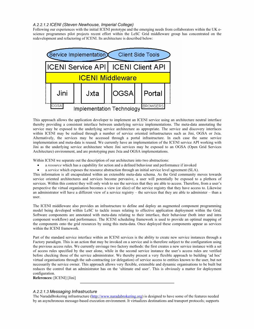
A.2.2.1.2 ICENI (Steven Newhouse, Imperial College) Following our experiences with the initial ICENI prototype and the emerging needs from collaborators within the UK e-science programmes pilot projects recent effort within the LeSC Grid middleware group has concentrated on the redevelopment and refactoring of ICENI. Its architecture is described below:
This approach allows the application developer to implement an ICENI service using an architecture neutral interface thereby providing a consistent interface between underlying service implementations. The meta-data annotating the service may be exposed to the underlying service architecture as appropriate. The service and discovery interfaces within ICENI may be realised through a number of service oriented infrastructures such as Jini, OGSA or Jxta. Alternatively, the services may be accessed through a portal infrastructure. In each case the same service implementation and meta-data is reused. We currently have an implementation of the ICENI service API working with Jini as the underlying service architecture where Jini services may be exposed to an OGSA (Open Grid Services Architecture) environment, and are prototyping pure Jxta and OGSA implementations. Within ICENI we separate out the description of our architecture into two abstractions:
• a resource which has a capability for action and a defined behaviour and performance if invoked • a service which exposes the resource abstraction through an initial service level agreement (SLA).
This information is all encapsulated within an extensible meta-data schema. As the Grid community moves towards service oriented architectures and services become pervasive, a user will potentially be exposed to a plethora of services. Within this context they will only wish to see the services that they are able to access. Therefore, from a user’s perspective the virtual organisation becomes a view (or slice) of the service registry that they have access to. Likewise an administrator will have a different view of a service registry – the services that they are able to administer – than a user. The ICENI middleware also provides an infrastructure to define and deploy an augmented component programming model being developed within LeSC to tackle issues relating to effective application deployment within the Grid. Software components are annotated with meta-data relating to their interface, their behaviour (both inter and intra component workflow) and performance. The ICENI scheduling framework is used to provide an optimal mapping of the components onto the grid resources by using this meta-data. Once deployed these components appear as services within the ICENI framework. Part of the standard service interface within an ICENI services is the ability to create new service instances through a Factory paradigm. This is an action that may be invoked on a service and is therefore subject to the configuration using the previous access rules. We currently envisage two factory methods: the first creates a new service instance with a set of access rules specified by the user alone, while in the second service instance the user’s access rules are verified before checking those of the service administrator. We thereby present a very flexible approach to building ‘ad hoc’ virtual organisations through the sub-contracting (or delegation) of service access to entities known to the user, but not necessarily the service owner. This approach allows very flexible, extensible and dynamic organisations to be built but reduces the control that an administrator has on the ‘ultimate end user’. This is obviously a matter for deployment configuration. References: [ICENI] [Jini]
A.2.2.1.3 Messaging Infrastructure The NaradaBrokering infrastructure (http://www.naradabrokering.org) is designed to have some of the features needed by an asynchronous message-based execution environment. It virtualizes destinations and transport protocols; supports
publish-subscribe methodology with XML Schema based topics; can link to Network performance modules and traverse (some) firewalls. Systems like IBM’s MQSeries, Microsoft’s Pastry and JXTA exhibit similar capabilities. Note this low-level publish-subscribe capability is different from that needed by the OGSA higher level notification schemes. References: [NaradaBrokering] [MQSeries]
A.2.2.1.4 Lightweight Middleware Technologies (Geoffrey Coulson, Lancaster University) Recent research in the middleware community has investigated lightweight and flexible approaches to the implementation and deployment of system software in general, and middleware in particular. This ‘lightweight middleware’ research has two main goals: i) to facilitate the construction , deployment and evolution of (middleware) platforms and services in their full generality, and ii) to facilitate the run-time management, adaptation, and dynamic reconfiguration of such platforms and services. By ‘platforms and services’ we mean both low-level, fundamental, ‘platforms’ (or ‘runtimes’) such as the software underpinning Web-Service invocation, CORBA-style invocation, media-streaming, tuple-space platforms, etc., and higher-level ‘services’ such as security, persistence, meta-data lookup, workflow, etc. Further, this research addresses the construction, deployment, evolution, and management of both existing (standardised) platforms (e.g., OGSA, EJB, JXTA etc.) and novel, niche platforms and services that might be useful for particular application areas or deployment environments (e.g. involving alternatives to the SOAP protocol when sending bulk, structured data over a wireless network or doing multipeer communication). Essentially, the research is working on toolkit support for developing, deploying and managing middleware and system software of all kinds. The approach most commonly taken in this work is to build systems in terms of a well-founded, lightweight, low-level, runtime component model. Such component models add very little in terms of performance overhead and memory footprint. As an example of such a model, we briefly describe Lancaster University’s OpenCOM [Clarke01A]. OpenCOM is language independent (i.e. components written in various languages can be combined arbitrarily), and system independent (it runs on Windows and UNIX platforms and even on bare hardware—this latter is achieved by recursively implementing parts of the OpenCOM runtime itself in terms of OpenCOM components). OpenCOM supports three main concepts: components, reflection, and component frameworks. Components serve as basic building blocks for constructing systems by composition (as advocated for example by Szyperski [Szyperski98A]). Reflection then provides means to discover the structure and behaviour of component compositions and to adapt , extend, and evolve these at run-time. Finally, component frameworks have the role of imposing domain-specific structure on component compositions, and ensuring architectural integrity during periods of adaptation/ reconfiguration. Examples of such ‘domains’ (taken from the Lancaster work) could be a ‘pluggable’ protocol stack framework, a framework implementation of the CORBA Portable Object Adapter, a framework implementation of application level multicast, or a framework for local resource management of threads, memory, and communication endpoints. Typically, these component models only comprehend the scope of a single address space. The idea is that where inter-address space communication is required, the required middleware to achieve this is itself built in terms of components. This enables great flexibility in deployment For example, a component framework implementing the IIOP protocol can be dynamically deployed into an address space to enable a set of ‘application’ components to interact. Subsequently, a set of components that implement a SOAP engine can be incrementally deployed if communication with a web service becomes necessary. Note that in this approach, the boundary between ‘operating system’, ‘middleware’ and ‘application’ is blurred: all of these are simply sets of components that are combined and deployed as required to meet an application need. It is important to emphasise that existing commercial component models such as EJB and the CORBA Component Model are not what we are talking about. These are used to build applications only; they are too heavyweight and prescriptive to implement systems themselves. The same applies to the Grid-oriented component models that have so far been developed, e.g. ICENI from Imperial College [ICENI]. The main forum for this ‘lightweight middleware’ research is the ACM/IFIP/USENIX ‘Middleware’ series of conferences. Apart from the OpenCOM work mentioned above, other examples of research efforts following a similar approach are as follows: THINK [Fassino02A] and Knit [Reid00A] are component models that have been used to build operating systems; Knit has additionally been applied in programmable networking environments, as has Click [Kohler99A]; K-Components [Dowling03A] is a component model that has been used primarily for real-time middleware; LegORB and Universal Inter-Connect (UIC) [Roman00A] are used to build middleware for ubiquitous computing environments; JavaPod [Bruneton00A] is a Java-specific solution for building middleware. Although it has been applied in a wide range of application environments, the ‘lightweight middleware’ approach has not yet been applied ‘in anger’ in Grid environments. Nevertheless, we believe that the approach has a lot to offer the Grid. It provides a well-founded basis for the flexible decomposition, recomposition, deployment, dynamic reconfiguration, and evolution of Grid middleware that is arguably much better suited to middleware for large scale,
heterogeneous, and dynamic environments than are today’s monolithic and ‘black box’ solutions. For example it has the potential to facilitate the provision of QoS-aware, adaptive, and self-managing platforms, to help provide structure and architecture in large scale systems, to facilitate the seamless coexistence of alternative platforms, and to support principled evolution of the middleware software base. However, considerable research is required to reap these potential benefits of the approach in the Grid environment.
A.2.3 Security Infrastructure A.2.3.1 Grid Security: Problems and Potential Solutions This section was written by Howard Chivers of York University and is available as York Department of Computer Science, Yellow Report YCS-2003-354 from http://www.cs.york.ac.uk/ftpdir/reports/ [Chivers03A]. The full report includes a bibliography that is omitted in these notes. A.2.3.1.1 Requirements and Issues Grid security requirements can be divided into project specific and generic. Generic requirements include some that apply to existing systems, but are stretched by scalability and administration complexity, and some that are new to highly distributed systems, such as remote delegation and distributed authorisation. This discussion is mostly about generic requirements. This is a wide topic; the Grid Security Architecture provides the rationale for the original grid requirements, a recent review of security issues in large distributed systems indicates that there are many issues still to be considered. The purpose of this section is to set the context for current problems, and how they might be resolved, so the following is a brief summary of generic requirements, from the point of view of the main stakeholders: users and resource providers. Users are either individual end users, or individuals responsible for projects that may be ‘virtual’ (span several organisations). Typical requirements are:
• speed – to introduce new users or groups into a system quickly. • flexibility - about the privileges provided to a group or individual. • privacy – to constrain the flow and use of private data in a system, including data used for authentication. • security – to be able to set up a grid with agreed security features (e.g. only allow data to flow to certain
processing sites). • delegated action – to allow the system to carry out a range of functions for the user when the user is not
present. • limits – to be able to place limits on the overall amount of resource consumed by particular groups or users.
Resource managers need:
• to be assured that their system is safe from software run by remote users. • to ensure that their system is not misused, for example as a platform to attack other systems. • to be able to charge for services. • to have a chain of accountability for actions that allows technical and administrative investigation and
resolution of problems. The Globus system has attempted to address these requirements, but has had to balance early delivery against security features, leading to the set of current issues that are widely cited:
Grid-map (mapping of global to local user IDs). This is difficult to manage (distribution of user authorisation data), static, and requires every co-operating resource provider to have entries for every user that might use that resource. Management. Each resource provider needs an agreement with each organisation that might host users or invoke processing (e.g. to establish the management process following system misuse). Some recovery requirements, such as revocation of certificates, are a concern because of their relative inflexibility, poor timeliness, and the high cost of re-establishing the system if a group or organisation, rather than an individual, is compromised. Firewalls. This is usually about the degree to which a firewall has to be opened to facilitate the use of Globus. Part of this problem is related to understanding configuration (grid systems are better configured as screened subnets
rather than ‘inside’ an organisation). However, even when this problem is solved (which it may be by web-services) the execution of remote software will still leave system administrators uneasy about the potential for system misuse. Proxies. The security weaknesses are well known (potentially exposed keys and the risk if they are compromised). These are mitigated by time limits, which themselves pose problems for some applications. The nature of a proxy (confers a subset of the user’s authority) is a more fundamental problem for some types of application. Uniformity. Industrial partners often express the concern that the uniform vision of grid processing will restrict their ability to apply problem specific security policies. Similar concerns are expressed by projects that manage health related data.
The common factor in these problems is ‘scalability and flexibility’, particularly in authorisation and policy management. The firewall question is slightly different, and there are other problems cited, such as software quality and the need for management mechanisms to publish vulnerability warnings and patches, that are not included here. A.2.3.1.2 Possible Solutions The use of a user’s identity as the basis for delegation in distributed systems has venerable roots in existing security practice. However, it is the fundamental source of the cited scalability and flexibility problems. To solve these issues requires an acceptance that in very large distributed systems it will be impossible to base authorisation on individual user identity: the security policy for any given machine must not require a list of all possible remote users. It is straightforward (in theory) to group users into roles; remote processing can then be authorised on behalf of groups. An individual user’s session can be given temporary authority by an authorisation service acting for the group and individual accountability can still be traced via a session pseudonym. Remote machines need only to associate privileges with temporary accounts assigned to the group. This scheme, which is similar to those developed by CAS and Shibboleth, can deal with some of the issues: user names are managed locally, providing more flexibility in forming and changing groups, sessions are identified pseudonymously enhancing the prospect of privacy. This scheme uses the idea of federation to group objects (in this case users) with similar properties (e.g. roles), and thereby factor the users x machines problem into manageable parts. An everyday example of federation is the consumer supply chain, which federates both suppliers (using distributors who act as middlemen) and users (shops). The concept of federation can be applied more generally than identification and authorisation, to solve a wider range of security issues: • Federation as a focus for system management would limit the number of bipartite agreements in which
participating resource providers would need to engage. • Federation as a focus for services would allow security (and other QoS) properties to be offered by different
‘distributors’, allowing the tailoring of security to users’ needs. • The notion of a session pseudonym can be extended to a ‘ticket’ (or capability), allowing a user federation to
establish arbitrary agreements with a distribution federation about the rights that may be granted by any particular ticket. This allows the construction of very flexible forms of delegation, since a federation would invoke services based on its own identify, rather than any delegation from a user.
Although the initial example federated users, these possibilities also motivate the need to federate resources. It may be useful to define a grid under these circumstances as a temporary binding between a federation of users and one or more federations of resource providers to deliver an agreed set of services. ‘The Grid’, meaning all possible grids, is a difficult security concept – it is hard to see how everything would have or need uniform security requirements, whereas it would be possible to establish security properties of a specific federation of resources, with a binding to a user federation representing an agreed security policy. Although this has been described as a four-layer scheme (users, user federations, resource federations, resources) it is likely that resource federations could well require the services of other resource federations to achieve further factoring, for either scalability or functional reasons. These federations are physical (both technical and organisational) entities, not merely notional sets of users or resources. Conclusion. It is possible to factor grid security requirements into manageable domains by federation, and this technique is capable of mitigating many of the problems perceived in current grid software. A.2.3.1.3 Implementation Issues At present, security mechanisms are being dealt with piecemeal (e.g. identification, authorisation, policy management), so although the idea of federation is emerging for user management, it may be slow to evolve as a comprehensive solution.
A complete authorisation/policy management system in a distributed system will need a range of components (user policy manager, authentication and authorisation databases, ‘policy agreement’ management tool, accountability and accounting tools as well as plug-in authorisation tools for web servers and operating systems). These components are linked by protocols (which themselves need security services at the transport layer) and message content definitions. Without detailed study it is hard to estimate the extent that existing components and protocols can be adapted to work in this way; it seems likely that web-services standards will eventually provide a sufficient transport capability, and that SAML (perhaps with grid additions) will similarly provide policy message content. Some existing authorisation tools should be adaptable, as will tools to map operating system temporary identities to group accounts.
A.2.3.1.4 Recommendations • Research the problem of security scalability in distributed systems. • Carry out a feasibility study on the extent that an initial federated security capability could be introduced from
a mixture of existing and new security tools. • Implement security infrastructure projects in the same way as grid applications: a coherent group of projects
demonstrating an integrated capability, not a set of independent mechanism-oriented projects. • Ensure that any resulting projects include customer facing integration & service elements to ensure
interoperability and quality. A.2.3.1.5 Other Issues Local User Identification: Federation will usefully push the question of user identification back to a local problem, but it will still be necessary to consider the transportability of user identification between systems. The main issue is ‘single sign on’ and the extent to which a user’s local logon can be integrated with access to a (cross organisational) user federation. The question of private key management, and other forms of identification will remain.
Recommendations: • Work is still needed on user identification, user-friendly management of private information (e.g. private PKI
keys), single-sign-on integration, and the transportability of policy and identification information between systems.
Project Specific Requirements: The UK e-science project list reveals some immediate security concerns, in order of prominence:
• Health • Industrial data confidentiality, and the management of data provenance • Safety
In grid terms, safety is a local problem; it mostly relates to the safety of specific experiments or facilities, and it is sufficient to ensure that the safety of each such system is self-contained. It is possible that general grid processing may be relied on for safety critical functions (e.g. to provide warning of bad weather or equipment malfunction), at this stage in the evolution of the grid, and for some time to come, such processing will remain advisory rather than critical, and can be discounted as an issue. Data confidentiality and provenance introduces few fundamental security problems, but it does mean that some grids will emerge with special confidentiality or integrity constraints. This implies that not all processing will be exactly alike, and future grid architectures will need to offer types or qualities of security services as attributes, in a similar way that resource providers will offer quality of service for communication or processing. This has been discussed above as a generic issue. From the project perspective, it is often possible to simplify the security implementation by incorporating risk management in the design process, rather than trying to add security mechanisms after the fact, and this should be encouraged. Health data poses an altogether different problem. The subject of privacy is under-explored and international solutions originating in the US are generally poorly regarded within the European/UK legislative frameworks. Privacy in systems that use the emerging trust management or authorisation services will depend on the semantics of the system services they authorise, and modeling the behaviour of complex services is an open question. This area requires fundamental research about the nature of the problem, requirements, security models, design methods, and how to use available implementation mechanisms and services. Recommendations:
• Place requirements on projects to o contain safety issues locally.
o carry out security analysis in parallel with system design. • Ensure that future grids are structured to offer security services, as well as functional services. • Research the privacy/heath problem and the question of providing security in service based systems.
References: [Chivers03A] [Pierce03A]
A.2.3.2 Possible Future Projects A.2.3.2.1 Harden VOMS from EDG (David Boyd, Rutherford-Appleton Laboratory) European DataGrid (EDG) has developed and put into production tools for managing Virtual Organisations (VO) via a convenient web interface, for allowing users to digitally sign Acceptable Use Policies (AUP) via the web, for publishing VO membership and for automatically constructing local access control policy files. This system is used with a Pool Accounts extension to Globus to allow users to "join the Testbed" without any manual intervention by site administrators - for example, to verify AUP acceptance or to create new accounts. The system also includes a Virtual Organisation Membership Service (VOMS), which permits users to obtain signed attributes proving VO membership and roles, and Grid Access Control Lists (GACL) and a toolkit to manipulate them, which are used to specify policies controlling access to resources in terms of certificate identities and VO memberships. All of the authorisation tools are potentially portable to other Unix variants, and would quickly benefit from being packaged for these platforms. Some development work in generalising the web interfaces to the VO management and AUP web systems would allow them to be applied to non-Particle Physics projects. Developing more detailed end-user documentation, including overviews of the security implications of different uses of the system, would make the VO and Pool Accounts approach more attractive to sites which have traditionally relied on static accounts and non-digitally signed AUP documents. GACL policy files and toolkit are designed to interoperate with other Grid authorisation systems, and this is an active area of co-ordination through the GGF Authorization Working Group (co-chaired by one of the GridPP developers) Consequently, this work would be ideally placed to influence this standards process, and produce software extensions to the EDG tools, to add support for other authorisation systems favoured by other UK Grid projects. References: [GridPP] [GGFAuth] [EDGWP2VOMS]
A.2.4 Workflow A.2.4.1 Selected Snapshots of Current Activities A.2.4.1.1 Workflow at Southampton (Luc Moreau) Under development by IT Innovations as part of the myGrid project. The Workflow enactment engine is a standalone component able to execute workflows expressed in a syntax close to IBM WSFL language. o It will support dynamic discovery and invocation of services; o It will support parallel execution of multiple threads; o It will be deployable as a Web Service. References: [ITInnovation] [MyGrid-A] [WSFL]
A.2.4.1.2 Workflow at Newcastle (Paul Watson) The ability to capture and enact computations is important for all the e-Science projects. Existing development of a workflow execution engine in the myGrid project (by IT Innovations) is the basis for the Workflow Enactment Grid Service (WEGS) for the Core Grid Middleware. The current myGrid enactment engine is based on Web Services, and so NEReSC is porting it to be a Grid Service. The WEGS in the initial release of the Core Grid Middleware will accept workflows written in the Web Services Flow Language (WSFL). However, NEReSC is already evaluating the possibility of providing support for the Business Process Execution Language for Web Services (BPEL4WS) in addition to WSFL. NEReSC is planning to follow the work of the GGF working groups in the important area of workflow/business process composition and intends to provide support for the Grid workflow standard when that is available. References: [ITInnovation] [MyGrid-A] [WSFL] [BPEL4WS] [NEReSC]

A.2.4.1.3 Workflow at Cardiff (Yan Huang) Research at Cardiff University in the workflow area was focused mainly on the development of an XML-based description language for scientific service-based workflows, and on an execution environment that takes a workflow as its input, and supervises its execution. The XML-based description language is called Service WorkFlow Language (SWFL), and it extends WSFL1 by supporting programming constructs, such as loops and conditional execution, commonly used in scientific programming – these are the same loop and conditional constructs found in the Java language. A loop in SWFL can be tagged as sequential or parallel to indicate whether different loop iterations can be run in parallel. In addition, SWFL permits very general data link mappings that allows a greater degree of control over the handling of complex data objects that are input to a service, compared with that available with WSFL. The execution environment is called Jini-based Service-oriented Grid Architecture (JISGA), and as the name indicates, is based on Jini for its implementation. An SWFL document is submitted to JISGA as its input. Using the WSDL documents of the services referenced in the SWFL, JISGA then creates a Java “harness” code that invokes the services, mediates their interaction, and returns results to the submission environment. JISGA compiles the harness code and runs it, thereby executing the workflow in the original SWFL document. A JISGA system is made up of an arbitrary number of WorkflowEngine and JobProcessor services. A WorkflowEngine service receives the SWFL documents submitted to JISGA and decides how they should be handled. A workflow submitted by a client can either be processed in blocking or non-blocking mode, and can either be processed sequentially or in parallel, using the follows workflow submission interfaces: public byte[] submitjob_block (String xmlDoc, byte[] inputData, boolean isParallel) throws RemoteException; public String submitjob_nonblock (String xmlDoc, byte[] inputData, boolean isParallel) throws RemoteException; In both cases, the first argument is the input SWFL argument, the second argument is the input data for the workflow marshaled into a byte array, and the third argument indicates if the job is to be done in parallel. The submitjob_block() interface returns a byte array of results, and the submitjob_nonblock() interface returns a job ID that can be used later to check for completion of the job and retrieve the output using the following method of the JSHousekeeper service: public Result getJobResult(String jobID); The WorkflowEngine service directly manages the execution of blocking sequential jobs. The JobProcessor services are responsible for the processing and execution of all other types of workflow submission. The main tasks performed by a JobProcessor service are to break down workflows to be processed in parallel into sequential sub-workflows, and then to manage their execution. JISGA makes use of JavaSpaces as a shared memory mechanism for returning the results of non-blocking workflow submissions and for communicating between interacting services. References: [SWFL] [Jini] [WSFL] [JISGA]
A.2.4.1.4 Workflow at IT Innovations (Mike Surridge) IT Innovation has met a requirement for workflow enactment in numerous projects going back to 1996. The original work was concerned with scheduling of task-graphs across distributed cluster systems in the EU projects PROMENVIR, HPC-VAO, TOOLSHED and more recently DIAMANT. The task graphs could contain parallel or non-parallel branches, as in:
B C
A A
B
C
In the UK E-Science programme, similar needs have arisen in orchestrating operation sequences on remote (i.e. distributed) grid services. IT Innovation’s contribution to myGRID has focused on this issue, and created a new enactor that is also being used and developed in three European projects including the grid projects GEMSS and GRIA. The new enactor is structured as follows:
1 WSFL = Web Service Flow Language
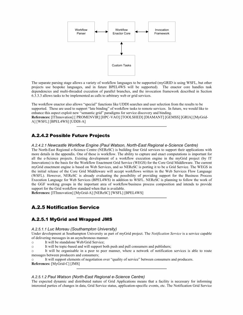
WorkflowParser
WorkflowEnactor Core
Custom Tasks
InvocationFramework
The separate parsing stage allows a variety of workflow languages to be supported (myGRID is using WSFL, but other projects use bespoke languages, and in future BPEL4WS will be supported). The enactor core handles task dependencies and multi-threaded execution of parallel branches, and the invocation framework described in Section 6.3.3.3 allows tasks to be implemented as calls to arbitrary web or grid services. The workflow enactor also allows “special” functions like UDDI searches and user selection from the results to be supported. These are used to support “late binding” of workflow tasks to remote services. In future, we would like to enhance this aspect exploit new “semantic grid” paradigms for service discovery and binding. References: [ITInnovation] [ PROMENVIR] [HPC-VAO] [TOOLSHED] [DIAMANT] [GEMSS] [GRIA] [MyGrid-A] [WSFL] [BPEL4WS] [UDDI-A]
A.2.4.2 Possible Future Projects A.2.4.2.1 Newcastle Workflow Engine (Paul Watson, North-East Regional e-Science Centre) The North-East Regional e-Science Centre (NEReSC) is building four Grid services to support their applications with more details in the appendix. One of these is workflow. The ability to capture and enact computations is important for all the e-Science projects. Existing development of a workflow execution engine in the myGrid project (by IT Innovations) is the basis for the Workflow Enactment Grid Service (WEGS) for the Core Grid Middleware. The current myGrid enactment engine is based on Web Services, and so NEReSC is porting it to be a Grid Service. The WEGS in the initial release of the Core Grid Middleware will accept workflows written in the Web Services Flow Language (WSFL). However, NEReSC is already evaluating the possibility of providing support for the Business Process Execution Language for Web Services (BPEL4WS) in addition to WSFL. NEReSC is planning to follow the work of the GGF working groups in the important area of workflow/business process composition and intends to provide support for the Grid workflow standard when that is available. References: [ITInnovation] [MyGrid-A] [NEReSC] [WSFL] [BPEL4WS]
A.2.5 Notification Service A.2.5.1 MyGrid and Wrapped JMS A.2.5.1.1 Luc Moreau (Southampton University) Under development at Southampton University as part of myGrid project. The Notification Service is a service capable of delivering messages in an asynchronous manner. o It will be standalone Web/Grid Service; o It will be topic-based and will support both push and pull consumers and publishers; o It will be organisable in a peer to peer manner, where a network of notification services is able to route messages between producers and consumers; o It will support elements of negotiation over “quality of service” between consumers and producers. References: [MyGrid-C] [JMS]
A.2.5.1.2 Paul Watson (North-East Regional e-Science Centre) The expected dynamic and distributed nature of Grid Applications means that a facility is necessary for informing interested parties of changes in data, Grid Service status, application-specific events, etc. The Notification Grid Service
(NGS) is based on a service produced within the myGrid project by the University of Southampton. The myGrid Notification Service provides a way for services to publish events and/or register interest in published events. As with the workflow enactment engine, the current myGrid Notification Service is based on Web Services and so it is being adapted to be OGSI compliant. The OGSI specification describes a notification portType and Service Data Elements (SDEs) through which NGS will provide the myGrid Notification Service functionality. References: [MyGrid-C] [OGSI]
A.2.6 Metadata and Semantic Grid A.2.6.1 Selected Snapshots and Current Activities A.2.6.1.1 UDDI Evaluation (Omer Rana, Cardiff University) A UDDI (Universal Description, Discovery, and Integration) repository stores metadata about the capabilities and interfaces of services. Service metadata is published to UDDI (either manually or by a service deployment tool), and the repository can be queried to discover services that match with specified capabilities and attributes. Query results are returned in the form of URIs that point to the metadata (usually in the form of a WSDL document) of each service satisfying the query. Metadata about a service needs to be provided in a specific format within the UDDI registry – such as the physical address/location of a service, contact phone number, the category of a service (generally specified based on a Tax Code ID or a Dun and Bradstreet (DUNS) number), etc. Such metadata is therefore specifically aimed at business services, and extending the data structure to register and provide support for services in another domain (such as scientific computing) may lead to incompatibilities. It is also not obvious how such extensions should be undertaken, and whether vendors are likely to support them. Further, search to a UDDI registry is based on a unique key, and capability based search is difficult to undertake. Another significant issue is the management of “top level” UDDI registries – currently undertaken by major vendors, such as IBM, Microsoft etc. Although the vendors indicate that replicated registries are likely to have identical content, there is no obligation for this to be the case. Therefore, there is likely to be inconsistent replication of UDDI registries, which may be further compounded by particular organisations managing their own “private” registry services. Therefore, although the approach adopted in UDDI is a useful one, the current implementations and availability of this technology may be limiting for supporting Grid Services. Alternative approaches to support registries include the Lightweight Directory Access Protocol (LDAP), which defines a network protocol for querying and updating X500-type directory servers. Although it does not offer a data model rich enough to encode Grid Services, it does have the advantage that many implementations are available (for Linux, Windows, and in programming languages like Java), and the current version of Globus MDS utilises it. The primary factor against the adoption of LDAP is its limited scalability over a distributed environment. A number of UDP multicast based approaches also provide the capability to support registry services, examples include Jini, the IEEE Service Location Protocol (SLP), and the Service Discovery Service from Berkeley. All of these approaches rely on the use of multicast requests to discover a registry service(s), and therefore are often restricted to a limited part of the network (using a limited number of hops/Time To Live) – and unlikely to scale to the Internet and the Grid. Jini provides a useful approach for enabling Java classes to expose and publish their interfaces with a “look-up” service, along with proxy objects that enable subsequent invocation of the Java classes. The proxy object needs to be downloaded by the client to initiate a session, and can thereby enable a number of different protocols to co-exist. The approach relies on the assumption that all services must define their interfaces using the Java type system, and also that subsequent search for suitable services in the registry (the lookup service) is restricted to these data types. Jini provides the notion of “leasing” (or soft state), which is also now available in OGSA. The Service Location Protocol uses a series of filter expressions to identify the location, types and attributes of a service within a part of the network. The query language is simpler than Jini’s. The Service Discovery Service also uses the same principles as SLP and Jini, and support a simple XML-based exact matching query type. The particular advantage offered by SDS is the use of secure channels to discover and publish service metadata. Furthermore, SDS servers can be organised into a hierarchy, enabling an administrator to analyse (and subsequently improve) performance at particular points in the hierarchy. Each SDS node in the hierarchy can hold an aggregated index of the content of its sub-tree. References: [UDDI-A] [UDDI-B] [GlobusMDS] [SLP] [NinjaSDS]
A.2.6.1.2 Unicore and MDS (John Brooke and Donald Fellow, Manchester Computing) Resource brokering is an essential tool for a scalable Grid. There are four functions that a resource broker should be able to perform on behalf of its clients. It should be able to discover sites advertising resources, to check that the

resources are able to accomplish the clients needs, to negotiate for quality of service and cost and to enable a contract between requestor and client to be agreed. The EuroGrid project is developing a broker that has such funcitionality building on the powerful abstractions in UNICORE (www.unicore.org). It is desirable to make this broker interoperable between Globus and UNICORE given the large market share that Globus currently has in Grid computing. In order to accomplish this an Interoperable Resource Broker is being developed based on the EuroGrid Resource Broker. This work has been carried out at the University of Manchester as part of the EU 5th Framework Project GRIP IST-2001-32257. More details of the project can be found at www.grid-interoperability.org. The GRIP broker builds on the functionality established by the EuroGrid Resource broker, details are at www.eurogrid.org
The broker searches for resources described via UNICORE to resources controlled by either UNICORE or Globus. The Globus resources are described via MDS schema using the GRIS and GIIS mechanisms. UNICORE has a series of structured abstractions expressed as Java classes that provide a rich vocabulary for describing hardware and software resources used in Grid workflow requests based on an Abstract Job Object (AJO). It also has a workflow language based on the UNICORE protocols (UPL). The interoperable resource broker is being designed to translate between the UNICORE and Globus Resource Description domains. Figure 1 shows the architecture design. The design is currently implemented with a basic translator. Work on the ontological translator is proceeding via a collaboration between the GRIP project and the IMG group at the University of Manchester working under the umbrella of ESNW. In the diagram NJS is the UNICORE network job supervisor that receives the brokering requests in the AJO format. The resource
lookup at the site is done under UNICORE by interrogating the Incarnation Data Base which grounds the AJO in site specific terms and on the Globus side via MDS. The eventual aim of GRIP is to express UPL in a standardized XML format, GRIP is actively contributing to the developments of the required standards and protocols by participation at GGF.
Figure 1: Broker Architecture (external components in grey) Here we describe the functionality available under UNICORE which is intended to be also implemented on sites running purely Globus. Single tasks can already be passed from UNICORE to Globus. Complex work-flow structures are possible in this framework supported by the UNICORE workflow constructs. These require research into an ontology capable of expressing such resource requests which is much richer than is currently provided via MDS information services. This is beyond the remit of the GRIP project which finishes in Dec 2003, therefore this fuller ontology will be a gap until funding is obtained to develop the ontology work. The EuroGrid broker can broker for UNICORE sites to assemble the following workflow tasks: • Data pre-processing at site A, simulation at site B, and post-processing at site C. • Iterative re-execution of a simulation until a termination criterion is met. The simulation may be a complex job, such as in item (1) above. • Simple application steering, in which a job “holds” itself at some point and waits for the user to check intermediate results before releasing the job. • More complex application steering, in which jobs are monitored and steered during execution. This may include visualization. • Conditional execution of tasks, or whole sub jobs, depending on the results of other tasks.
NJS
Broker
UnicoreBroker GlobusBroker
IDB Translator Filter
BasicTranslator OntologicalTranslator
OntologyMDS
(GIIS/GRIS)
delegates ResourceCheck
performs LDAP search driven by filters
delegates translationlooks up staticresources creates
looks up resources
uses structuredvocabulary

• Ensemble simulation of many cases at different sites and subsequent collation of results centrally. • Simple meta-computing jobs.
Developing a Grid Resource Ontology has desirable consequences beyond the initial aims of UNICORE-Globus interoperablity. The UK is developing a range of middleware that needs to describe resources and it is highly desirable that mechanisms exist to enable this middleware to interoperate and to adhere to agreed standards. A Grid Resource Ontology is a much more flexible tool for such interoperability than a fixed language for reasons which are described more fully in the document “Abstraction of Resource Broker Functions” presented to the GPA-RG at GGF7 and available from
http://www.gridforum.org/Meetings/ggf7/docs/default.htm
or from the GPA-RG home pages.
Details of the first specification of the interoperable broker which has already been implemented are given in the document “Abstraction of Resource Broker Interface” available at the GRIP Web site
http://www.grid-interoperability.org
References: [Unicore] [GRIP] [EuroGrid] [Brooke03]
A.2.6.1.3 RGMA (David Boyd, Rutherford-Appleton Laboratory) R-GMA (Relational Grid Monitoring Architecture) has been developed in the European DataGrid (EDG) project as a Grid Information and Monitoring System for both the Grid itself and for use by applications. It is based on the GMA from GGF, which is a simple Consumer-Producer model. The special strength of this implementation comes from the power of the relational model. A global view of the information is offered, as if each Virtual Organisation (VO) had one large relational database. A number of different Producer types have been coded. They have different characteristics; for example some support streaming of information. Combined Consumer/Producers are also provided, which are able to combine information and republish it. At the heart of the system is the mediator, which for any query is able to find and connect to the best Producers to do the job. In addition to specific R-GMA sensors able to publish information, tools are available to invoke MDS info-provider scripts and publish the resulting information via R-GMA and also to take R-GMA and publish to an LDAP server. Work is required to improve the documentation – especially the user guide. Porting to other Unix platforms will be performed to make the code more readily available to a larger set of users and to increase the robustness of R-GMA. Currently distribution is via RPMs which are produced for RedHat. Packaging suitable for other platforms should be developed – ideally built from the same generic package descriptions. Currently the code works without security or with the EDG security module. This should be changed to allow different authentication schemes to be adopted. References: [EDGWP3RGMA] [RPM]
A.2.6.1.4 Semantic Grid (Nigel Shadbolt, Southampton University) The first explicit characterisation of the Semantic Grid (www.semanticgrid.org) appeared in a report commissioned for the UK e-Science Programme [DeRoure01A] subsequently appearing in [Berman03]. This work sought to take a service-oriented approach to the Grid and embodied two fundamental assumptions. The first is that an agent-based characterisation of Grid services was likely to be helpful. The second was the importance of having explicit semantic descriptions of the content, processes and services deployed on the grid. Subsequently work on the Semantic Grid at Southampton can be found embodied in a number of projects. The first of these is GEODISE (www.geodise.org) in which ideas from the Semantic Web and knowledge engineering are being incorporated into a set of services to support the engineer in design optimisation. Two other projects MIAKT (www.aktors.org/miakt) and CoAKTinG (www.aktors.org/coakting) have arisen from the Advanced Knowledge Technologies (AKT) project (www.aktors.org) led from Southampton. AKT is developing a wide range of technologies and services for the Semantic Web covering the whole knowledge life cycle - acquisition, modelling, retrieval, reuse, publishing and maintenance. MIAKT is attempting to develop and apply ontologies as annotations for medical images. It is also uses Internet Reasoning Services (IRS kmi.open.ac.uk/projects/irs/) to invoke Grid based processing for image registration (a computationally intensive task of aligning images taken at different times). The IRS takes a high level approach to defining the knowledge level competencies of a service – the sort of processing and problem solving a service is able to perform. In CoAKTinG we are looking to enhance the capability of Access Grids and other collaborative videoconference environments. In particular, we are using software that can capture group decision-making and use its outputs as annotations on the various content produced by the meeting.

Southampton is also a partner in MyGrid in which a knowledge-oriented view of Grids is adopted in order to discover services and assemble workflows for bioinformaticians. References: [Berman03A] [DeRoure01A] [SemanticGrid] [Geodise] [MIAKT] [AKT] [CoAKTinG] [IRS]
A.2.6.1.5 SDT Semantic Discovery Toolkit (Luc Moreau, Southampton University) Under development at Southampton University as part of the myGrid project. The Service directory toolkit is a toolkit for deploying service directories in multiple ways:
All information about published services will be represented in a triple store supporting the RDQL query language; Several interfaces will be supported for registering and searching services (including UDDI, JAXR, DAML-S,
semantic annotations, biomoby subset); Services will be deployable in multiple distributed configurations, including standalone service directory,
personalised federation of registries, or tunnelling; Service directory will allow third parties to attach annotations to service descriptions (e.g. semantic description,
perceived reliability, trust). Configurations will be specified by management policies.
References: [MyGrid-A]
A.2.6.1.6 Metadata Management (Kerstin Kleese, Daresbury Laboratory)
(a) General Scientific Metadata Format The Data Management Group of the CCLRC e-Science Centre is involved in a range of research projects to develop tools to further the collection of metadata, the integration of different data resources and their exploration potential. The group has over the past two years developed the CCLRC Scientific Metadata Format (version published as DL report http://www-dienst.rl.ac.uk/library/2002/tr/dltr-2002001.pdf). The Metadata format is currently available as Ontology, XML-Schema and Database implementation and is used for a variety of projects. The metadata is currently used for two different purposes to help to collect metadata at facilities and in projects who have not done so before and as an interchange format (description of information required) with existing facilities. Examples for its application are a number of CCLRC internal departments: ISIS, SRD (test data only), as well as a range of UK e-Science projects: a Polymorphism metadata database (Sally Price, UCL, e-Materials project), a Combinatorial Chemistry metadata database (Richard Catlow, RI, e-Materials project) and a set of Surface and Surface Fluid Interaction metadata databases for the NERC e-Minerals Project (Martin Dove, Cambridge, Richard Catlow, RI, David Price, UCL, Stephen Parker, Bath,). Otherwise the CCLRC Scientific Metadata Format is used to interchange information between existing sites within the DataPortal tool. References: [Matthews01A] [UKeS-B] [CCLRCeSCDP-A]
(b) CCLRC Data Portal The Data Management group of the CCLRC e-Science Centre has developed a cross-disciplinary DataPortal, which allows searching various data facilities in parallel, exploring their metadata catalogues and accessing their data. It was important for us to preserve the independence of existing data facilities, therefore the Portal's work does not require any specific database technology, metadata schema locally or user administration (that is it has to be done electronically so that linkage to certificates is possible). We are currently using XML Wrappers to 'translate' Portal queries into local formats and to generate the replies to the portal. In the future it is hoped that we can make use of ontology mapping services instead as well as a more universal XML query language. To be able to formulate queries and to collate results, we have developed a General Scientific Metadata Format, which is used by the system. The DataPortal has recently been released in its 3rd version (see http://ws1.esc.rl.ac.uk/web/projects/dataportal to download software) and is now based on web services technologies (WSDL, Apache's Axis SOAP, UDDI), using UK e-Science Certificates for authentication (for a trial access go to http://esc.dl.ac.uk:9000/dataportal/index.html ). The code consists of a variety of independent modules with web services interfaces based around major functionalities e.g. shopping cart, authentication and authorisation. The Portals security system is tied in with the existing security measures at each of the data facility sites. The user is e.g. able to pose queries, explore the metadata from various sites, access the data itself, save search results in a permanent shopping cart and transfer data to other systems or services. The CCLRC implementation of the Portal currently links three CCLRC test data repositories (ISIS, BADC and SRD) and one external site (MPIM in Germany). More operational catalogues will be added over the coming months. Furthermore, different instances of the Portal are being set up for other projects, such as the e-Minerals Mini Grid and the e-Materials project. The Portal's web services technology allows easy linkage to other web services such as they are provided e.g. by the CCLRC HPCPortal. In the future we will encourage local data sites to register their data with local SRB servers if that is appropriate, so that the metadata will no longer contain hard to maintain physical links to the data, but instead incorporates 'soft links' to SRB logical names.
References: [CCLRCeSCDP-A] [CCLRCeSCDP-B] [CCLRCeSCHPC] [eMinerals] [eMaterials] A.2.6.2 Possible Future Projects A.2.6.2.1 Semantic Grid Expectations (Nigel Shadbolt, Southampton University) Future developments of the Semantic Grid are inextricably bound up with those of the Semantic Web. For example, it is already possible for grid developers to exploit RDF standards and tools. Moreover, the W3C efforts towards an ontology web language are important for the Semantic Grid too. It is to expected that the following will be key areas for development: Ontologies – there will be a central role for the use of shared conceptualisations for both the structural content and processes that will be supported on the Grid. Thus, heterogeneous and distributed data integration and database access will be mediated through ontologies; ontologies will determine workflow composition and also facilitate service discovery and composition. Annotation - the use of ontologies will call for tools that can carry out large-scale annotations of content with the metadata that these ontologies represent. Maintenance – the use of extended annotations and ontologies will carry with it significant maintenance overheads. Ontologies have to be managed and maintained. In some areas of science and engineering the concepts are evolving and changing at a dramatic rate requiring new kinds of annotation to be incorporated into metadata repositories. Intelligent Brokering and Service Discovery – this will increasingly feature as services are composed on demand. There could be considerable scope for negotiation between services. For example, as trade offs are considered with respect to features such as speed of delivery, cost, numbers of completed runs, amounts of redundancy etc. References: [SemanticGrid] [OWL]
A.2.6.2.2 Intergrid service registry (Mike Surridge, IT Innovation) One feature of the OGSA standard is that it supports a factory/instance model for services, in which users can create their own service instances to handle their service invocation requests and maintain any state required by the application. A user must first locate a suitable factory and create their service instance, on which they can then invoke operations. However, the “native” invocation model of the web is “session” oriented – one retains a session identifier (possibly stored in a cookie), and uses this when invoking remote services. In fact, the OGSA standard does not preclude this model – it is likely that factory services will need to use it. IT Innovation plans to propose a new “semantic grid” project in which the distinctions between these two models are abstracted by the invocation framework (extending the work described in Section 6.3.3.3). In principle this would allow applications to be developed that can use services from different grids, regardless of whether they are deployed in a factory/instance or a session-based grid-hosting infrastructure. A key challenge for this work is to define standards for service descriptions and intergrid service registry federation, such that an intergrid user can discover the correct starting point from which to invoke a service independently of whether it might involve a factory. References: [ITInnovation] [OGSA]
A.2.6.2.3 Provenance Specification (Luc Moreau, Southampton University) myGrid will offer some provenance support, by recording what is being executed and when. Our work will focus principally on the type of data (and their ontologies). The solution will be simple, centered on the enactment engine publishing such an information into a notification service, with a consumer storing it in a repository. In reality, a solution is required that is distributed, scalable, and secure, not only for registering provenance data but also for reasoning about it. This is a new research area in itself: it requires us to design new algorithms for submitting provenance data asynchronously and securely, to study their correctness, and to design high performance services able to execute them. References: [MyGrid-D]
A.2.6.2.4 SRB Evaluation (Kerstin Kleese, Daresbury Laboratory) Storage Resource Broker (SRB) is a client-server based middle-ware initially developed by SDSC in the mid-Nineties to provide uniform access interface to different types of storage devices. SRB provides an uniform API that can be used to connect to heterogeneous resources that may be distributed and access data sets that may be replicated. SRB is being
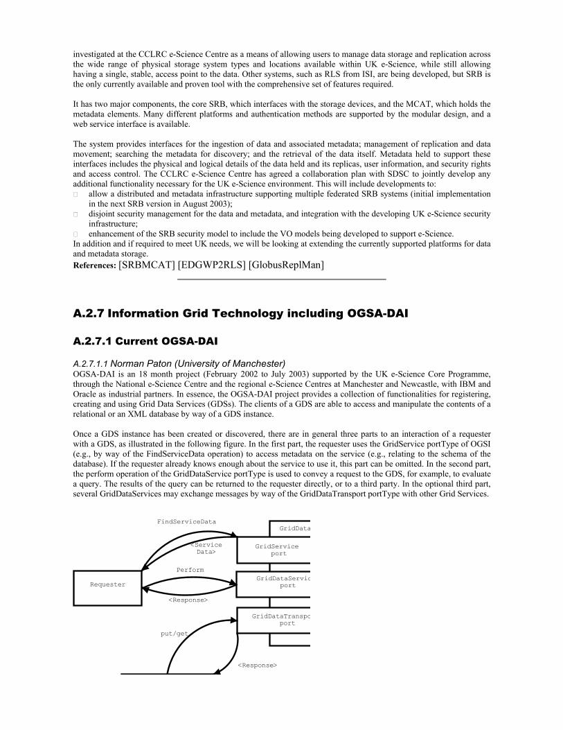
investigated at the CCLRC e-Science Centre as a means of allowing users to manage data storage and replication across the wide range of physical storage system types and locations available within UK e-Science, while still allowing having a single, stable, access point to the data. Other systems, such as RLS from ISI, are being developed, but SRB is the only currently available and proven tool with the comprehensive set of features required. It has two major components, the core SRB, which interfaces with the storage devices, and the MCAT, which holds the metadata elements. Many different platforms and authentication methods are supported by the modular design, and a web service interface is available. The system provides interfaces for the ingestion of data and associated metadata; management of replication and data movement; searching the metadata for discovery; and the retrieval of the data itself. Metadata held to support these interfaces includes the physical and logical details of the data held and its replicas, user information, and security rights and access control. The CCLRC e-Science Centre has agreed a collaboration plan with SDSC to jointly develop any additional functionality necessary for the UK e-Science environment. This will include developments to:
allow a distributed and metadata infrastructure supporting multiple federated SRB systems (initial implementation in the next SRB version in August 2003);
disjoint security management for the data and metadata, and integration with the developing UK e-Science security infrastructure;
enhancement of the SRB security model to include the VO models being developed to support e-Science. In addition and if required to meet UK needs, we will be looking at extending the currently supported platforms for data and metadata storage. References: [SRBMCAT] [EDGWP2RLS] [GlobusReplMan]
A.2.7 Information Grid Technology including OGSA-DAI A.2.7.1 Current OGSA-DAI A.2.7.1.1 Norman Paton (University of Manchester) OGSA-DAI is an 18 month project (February 2002 to July 2003) supported by the UK e-Science Core Programme, through the National e-Science Centre and the regional e-Science Centres at Manchester and Newcastle, with IBM and Oracle as industrial partners. In essence, the OGSA-DAI project provides a collection of functionalities for registering, creating and using Grid Data Services (GDSs). The clients of a GDS are able to access and manipulate the contents of a relational or an XML database by way of a GDS instance. Once a GDS instance has been created or discovered, there are in general three parts to an interaction of a requester with a GDS, as illustrated in the following figure. In the first part, the requester uses the GridService portType of OGSI (e.g., by way of the FindServiceData operation) to access metadata on the service (e.g., relating to the schema of the database). If the requester already knows enough about the service to use it, this part can be omitted. In the second part, the perform operation of the GridDataService portType is used to convey a request to the GDS, for example, to evaluate a query. The results of the query can be returned to the requester directly, or to a third party. In the optional third part, several GridDataServices may exchange messages by way of the GridDataTransport portType with other Grid Services.
GridData
<ServiceData>
GridService port
GridDataServicport
GridDataTranspoport
Requester
FindServiceData
Perform
<Response>
put/get
<Response>

The OGSA-DAI software supports the mySQL, DB2 and Oracle relational databases and the Xindice XML repository. The OGSA-DAI project is also providing input to, and contributing a reference implementation for, the ongoing activity within the Database Access and Integration Services Working Group of the Global Grid Forum. OGSA-DAI software is available from www.ogsa-dai.org.uk. As well as the development of core data access services, OGSA-DAI will deliver prototype software that demonstrates the use of distributed query processing techniques for integrating data from multiple GDSs. This prototype software will also provide combined use of GDS and other Grid Services, for example by allowing the results of a query over multiple GDSs to be conveyed to an analysis service, and for the results of the analysis to be related to values accessed through further distributed GDSs. References: [OGSA-DAI] [UKeS-C] [ESNW] [NEReSC]
A.2.7.1.2 Dave Berry (National e-Science Centre) The OGSA-DAI project has produced and released the following grid services:
1. Grid Data Service (RDBMS and XMLDB) 2. Grid Data Service Factory 3. Grid Data Service Registry
These are (almost entirely) database agnostic. Essentially, the "front" of the GDS is the same for relational and XML databases, and to add support for a new database someone would essentially need to write a new configuration file which provides a binding to that database. In theory, no code needs to be changed to support e.g. DB/2 or Oracle as opposed to MySQL - in reality there needs to be minor modifications due to the way that the "standard" URI scheme for opening a connection to a database is not quite as standard as we'd have liked. GDSF is completely database agnostic, except where you choose to include support for any proprietary database management functionality. References: [OGSA-DAI]
A.2.7.1.3 Paul Watson (North-East Regional e-Science Centre) The North-East Regional e-Science Centre (NEReSC) is building four Grid services to support their applications with more details later in the appendix.
1. OGSA-DAI Many of the projects at NEReSC require access to database management systems over the Grid. The Open Grid Services Architecture – Database Access and Integration (OGSA-DAI) service provides a consistent way to access relational and XML data on the Grid. The OGSA-DAI implementation, discussed in (reference to your section on OGSA-DAI), is therefore included in the Core Grid Middleware.
2. OGSA-DAI Distributed Query Processing NEReSC is directly involved in the design and implementation of the OGSA-DAI Distributed Query Processing (DQP) Grid Service (reference to your section on OGSA-DAI DQP), which enables Grid applications to run queries over distributed data resources. A number of e-Science research projects will use this service to federate data from multiple databases over the Grid.
References: [OGSA-DAI] [NEReSC]
A.2.7.2 Selected Snapshots of Current Activities A.2.7.2.1 Environmental Grids (Bryan Lawrence, Rutherford-Appleton Laboratory) There are a number of initiatives both nationally and internationally in the environmental sciences, here we concentrate on grids in the atmospheric, oceanographic, and earth observation areas. The NERC DataGrid: The NERC DataGrid is a UK NERC/national core e-science project that began in September 2002. The main aim is to build a grid that connects data collections held by individual scientists with the British Oceanographic and Atmospheric Data centres, and develop the technology to extend that grid to link into the other environmental disciplines for which NERC holds curated data. Clearly work is at an early stage, and at the moment the project is concentrating on developing: (i) a schema which is capable of being used as intermediate schema between the individual highly specialised schema typical of the disciplines involve (e.g. oceanography and atmospheric sciences);

and (ii), a simplified data model which can support observational and simulated data in existing formats and using existing transport mechanisms (including OPeNDAP). The current plan is to use SRB to manage data held amongst the larger centres and a specialised grid-service (based on OPenDAPg developed by ESG, discussed below) for data delivery to the wider community. It is not yet clear whether OGSA/DAI will play a role in querying databases, or an approach based on OAI harvesting of metadata will be used, or a combination of both. Additional work is also being carried out on editors to make it easier for data providers to create the extra metadata required for the grid technologies to be useful, on conventions and standards for the content to go into the schema, and on tools to manipulate data in the grid environment. The US Earth Systems Grid (ESG II): Following on from ESGI, this project began in 2002 and is aimed at making the TB of data produced by climate simulations available to users throughout the continental US. Current testbeds demonstrate the integration of a wide range of globus based technologies with tools to extract data from deep storage and move it round the country. One key piece of work has involved integrating GridFTP into the OPeNDAP transport system so that OpeNDAP servers can utilise fast reliable secure data services (OPenDAPg). Further work on metadata systems is underway including both the development of simplified schema (as in NDG) and potentially on using OGSA/DAI to find and utilise that metadata. They are also working on the use and extension of globus tools to provide community authentication and rights management. Client software for the ESG is being based on portals, and both fat- and thin-client technologies. EU DataGrid includes WP9 on Earth Observation data: here the application is to link data processing of EU data in different national institutions (primarily Italy, France and the Netherlands) using the EU DataGrid infrastructure. References: [NERCDataGrid] [OPeNDAP] [SRBMCAT] [OPenDAPg] [ESG] [OAI] [GlobusGridFTP] [EDGWP9]
A.2.7.2.2 AstroGrid (Tony Linde, Leicester University) The AstroGrid project seeks to develop the world's first implementation of a Virtual Observatory (VO) in which hundreds of data archives and astronomical tools are made available to astronomers via standards-based desktop and web applications. The project has just now (early 2003) entered its build phase with a fixed completion date of December 2004. In order to develop working services the project will initially develop components as web services, refactoring them as grid services in the second half of the build while extending the functionality to make use of advanced grid technologies. AstroGrid has defined a high-level model of VO components, of which the key ones include:
Portal Registry Community Data Centre and Dataset Access MySpace Log
The interface between each of these components will require standards to be defined, many of them in an effort by the international astronomical community (via the IVOA – International Virtual Observatory Alliance – in which AstroGrid plays a leading role). There are substantial challenges in this project to those developing basic Grid and Data Grid services. The Portal component must be able to adopt the identity of a user so that jobs can be submitted, data accessed, resources utilised, all without the user having to reconfirm their identity. The Registry must contain sufficient metadata about datasets that users can identify ones which have a high probability of being able to satisfy their queries, before those queries are submitted. A Community will contain users and groups of users with widely varying rights of access over data; for instance, a subset of data might be only available to one astronomer but that person might want to delegate some access rights to certain colleagues – and after two years the data reverts to being available to all those with rights of access to the dataset as a whole. Dataset access provides the greatest challenge. Data might be held in relational, object-oriented, xml-based or any other kind of database; it might be in flat files of many different formats: both ascii and binary; it might represent tabular, image, spectral or other types of data. The VO must make all of this data accessible via a standard query language which recognises the type of data involved but allows interpolation so that a query might refer to a data item which must be calculated from other items in the actual dataset. MySpace perhaps offers an area of development which will prove most useful to other projects. The concept is of a virtual directory space of data items, located in databases or files anywhere on the Grid, but which the user can see and manipulate through an Explorer-type interface. AstroGrid has adpated this idea already to cover both data centre cache
provision and community-based private storage. This is a faciltiy which users in many fields will want available and is one which could be a standard feature of any data grid. Another common tool that all projects would wish to deploy is a logging facility. The ability to log events with custom identifiers is common to many operating systems and should also be a standard feature of the grid. References: [AstroGrid] [iVOA]
A.2.7.2.3 The Storage Resource Broker (Kerstin Kleese, Daresbury Laboratory) The Storage Resource Broker (SRB) was developed by the San Diego Supercomputing Center (SDSC) and is a professional tool to manage data across various storage devises and institutions. Initially release in 1996 it is now available in version 2.0. It provides transparent access and management capabilities to data stored in file systems, tape stores and databases across distributed sites and institutions. The system provides the user with a logical abstraction from the physical instances of the data and allows some basic annotation of the data held. The SRB system is a distributed system comprised of 3 major components:
The Metadata Catalogue (MCAT) database The SRB Server The SRB Client
Each SRB system must currently consist of a single MCAT database and one or more SRB Servers and SRB clients. Note there has been some confusion in the community that SRB runs off a single world-wide MCAT database. This is not true. Anyone wishing to set up an SRB is free to create their own MCAT and in fact CCLRC has done so successfully. The MCAT database is a metadata repository that provides a mechanism for storing information used by the SRB system. This includes both internal system data required for running the system and application data regarding data sets being brokered by SRB e.g. your own metadata. SRB makes a clear distinction between these two types of data. At least one SRB Server must be installed on the node that hosts the MCAT database. MCAT performs the following data management operations:
Stores Metadata on Data sets, Users, Resources, Proxy Methods. Maintains replica information for data & containers. Provides “Collection” abstraction for data. Provides “Global User” name space & authentication. Provides Authorization through ACL & tickets. Maintains audit trail on data & collections. Maintains metadata for methods and resources. Provides Resource Transparency - logical resources.
The SRB Server is a middleware application that accepts requests from clients and obtains the necessary data sets. It queries the MCAT database to gather information on datasets and supplies this back to the SRB client. The SRB server can operate in a federated mode, whereby it can request another SRB server to obtain the necessary data on its behalf. The data is then transparently passed back to the client. The SRB Client is an end user tool that provides a user interface to send requests to the SRB server. There are 3 main implementations of this: command line, MS Windows GUI (InQ) or web based (MySRB). A recent addition is the MySRB server component. This allows all access to storage via a thin client. The MySRB server is actually an application server middleware component that acts as a client to service multiple thin client sessions. This option is proving popular as it allows access to the system from anywhere with an internet connection. All three components are supported on a wide variety of systems. MCAT: Oracle, IBM DB2, Sybase and Postgres. SRB Server: Microsoft Windows: NT, 2000, NT and XP, Unix: Linux, 64 bit Linux, Solaris, Sun OS, Irix, AIX, UNICOS (deprecated), Tru64 Unix/OSF (deprecated) and BSD (deprecated), MacOS X. The server gives you the ability to manage data in NT and Unix file systems, Tape Stores and Databases.
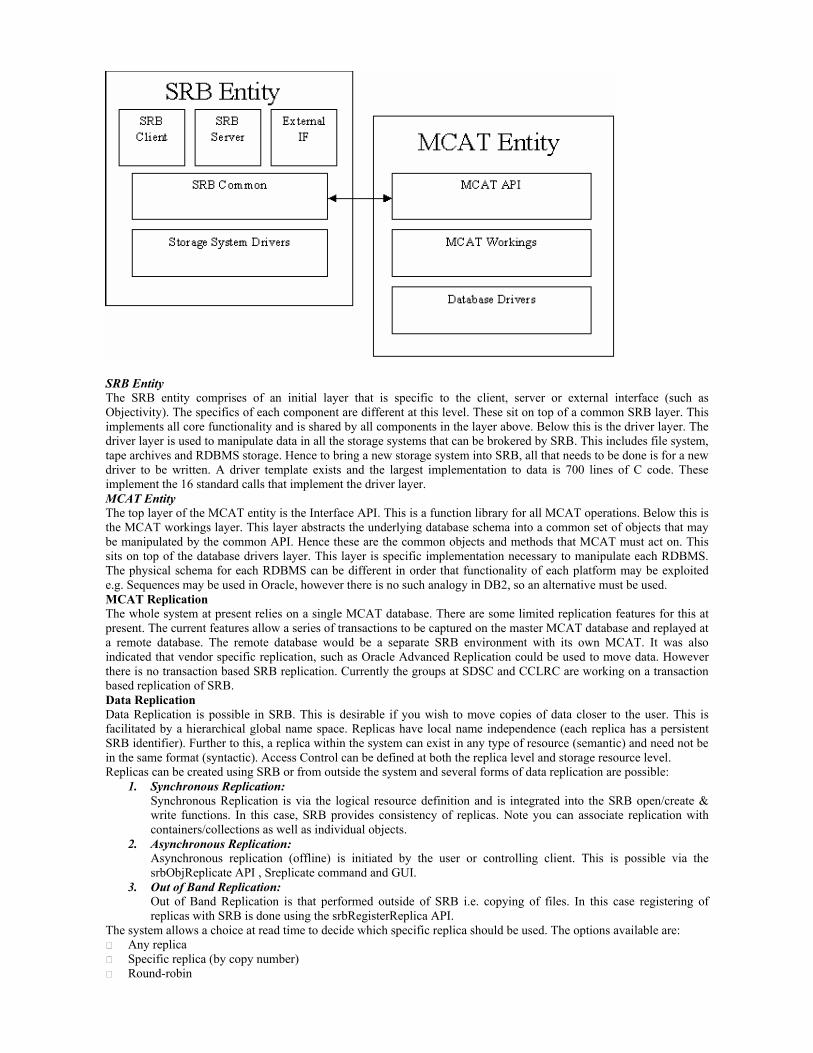
SRB Entity The SRB entity comprises of an initial layer that is specific to the client, server or external interface (such as Objectivity). The specifics of each component are different at this level. These sit on top of a common SRB layer. This implements all core functionality and is shared by all components in the layer above. Below this is the driver layer. The driver layer is used to manipulate data in all the storage systems that can be brokered by SRB. This includes file system, tape archives and RDBMS storage. Hence to bring a new storage system into SRB, all that needs to be done is for a new driver to be written. A driver template exists and the largest implementation to data is 700 lines of C code. These implement the 16 standard calls that implement the driver layer. MCAT Entity The top layer of the MCAT entity is the Interface API. This is a function library for all MCAT operations. Below this is the MCAT workings layer. This layer abstracts the underlying database schema into a common set of objects that may be manipulated by the common API. Hence these are the common objects and methods that MCAT must act on. This sits on top of the database drivers layer. This layer is specific implementation necessary to manipulate each RDBMS. The physical schema for each RDBMS can be different in order that functionality of each platform may be exploited e.g. Sequences may be used in Oracle, however there is no such analogy in DB2, so an alternative must be used. MCAT Replication The whole system at present relies on a single MCAT database. There are some limited replication features for this at present. The current features allow a series of transactions to be captured on the master MCAT database and replayed at a remote database. The remote database would be a separate SRB environment with its own MCAT. It was also indicated that vendor specific replication, such as Oracle Advanced Replication could be used to move data. However there is no transaction based SRB replication. Currently the groups at SDSC and CCLRC are working on a transaction based replication of SRB. Data Replication Data Replication is possible in SRB. This is desirable if you wish to move copies of data closer to the user. This is facilitated by a hierarchical global name space. Replicas have local name independence (each replica has a persistent SRB identifier). Further to this, a replica within the system can exist in any type of resource (semantic) and need not be in the same format (syntactic). Access Control can be defined at both the replica level and storage resource level. Replicas can be created using SRB or from outside the system and several forms of data replication are possible:
1. Synchronous Replication: Synchronous Replication is via the logical resource definition and is integrated into the SRB open/create & write functions. In this case, SRB provides consistency of replicas. Note you can associate replication with containers/collections as well as individual objects.
2. Asynchronous Replication: Asynchronous replication (offline) is initiated by the user or controlling client. This is possible via the srbObjReplicate API , Sreplicate command and GUI.
3. Out of Band Replication: Out of Band Replication is that performed outside of SRB i.e. copying of files. In this case registering of replicas with SRB is done using the srbRegisterReplica API.
The system allows a choice at read time to decide which specific replica should be used. The options available are: Any replica Specific replica (by copy number) Round-robin

Nearest Resource characteristics Timestamp or other characteristics Meta characteristics (user defined metadata & annotations)
Once replicated files can be locked while changes are applied. Basic versioning for data within SRB is also available. SRB is very reliable and versatile for the management of distributed data and has been well adapted for the use in the Grid environment. It will be used by a number of UK e-Science projects in the near future to manage their data on the grid. The BIRN project is already using it successfully in the US http://www.nbirn.net a complete list of projects using SRB can be found under http://www.npaci.edu/dice/srb/Projects/main.html. References: [SRBMCAT]
A.2.7.3 Possible Future Projects A.2.7.3.1 Capital Radio (Alistair Dunlop, Capital radio Group) Capital Radio is the UK's leading commercial radio group, with greater revenues and profits than any other commercial radio company. This is achieved through a total of 20 analogue radio licences broadcasting to over half of the UK's adult population. These 20 analogue licenses have a near one-to-one correspondence with physical radio studios located across the length and breadth of the UK. Although Capital Radio Group has a large number of separate offices within the country, each radio station has operations that are both centrally and locally directed. There are specific sites that perform specialised functions for the group where their actions can affect the behaviour of sub-group of offices. For example, the London office is responsible for sales of National advertising campaigns. These sales affect the commercial airtime of local radio stations. Another example would be of a single radio station promoting a new artist or new material that is picked up by other stations. These are two simple but common examples that illustrate that the flow of information around the group is multidirectional. A central server solution is inappropriate due to quality of service requirements. First, the stations need to be able to operate in isolation even in the event of network or server failures. Secondly, many data transfers are time critical that could not be met by a centralised architecture in peak conditions. These requirements to have collaborating islands of networks has lead to the consideration of data grid technologies to solve these problems. Reference: [CapitalRadio] [JXTA]
A.2.7.3.2 Futures of OGSA-DAI (Norman Paton, University of Manchester) Current funding for OGSA-DAI ends in July 2003. The current OGSA-DAI project will produce database access services for use with relational databases and XML repositories. A proposal for a follow-on project has been approved by TAG, which will seek: To extend the functionality of the OGSA-DAI Grid Database Services, for example, to support a richer collection of data movement mechanisms, more comprehensive transaction management, more flexible data transformation, more comprehensive metadata, and more fully integrated notification support. To improve performance and dependability, for example to exploit emerging data movement services and transport bindings, to exploit replicated data or materialised views, and to improve scheduling and resource allocation for complex requests. To develop higher-level services and application patterns, for example, by developing the prototype distributed query processor into a supported middleware component, by providing facilities to support selective replication of GDS managed data, and by supporting archive management using GDSs. As the GGF standardisation process for OGSI, OGSA and DAIS will all continue well beyond the end of the current OGSA-DAI project, the follow-on would seek to track and inform standards in various parts of the GGF, provide a reference implementation for the DAIS standard as it evolves during the GGF process, and inform future versions of the DAIS standard. It seems likely that many GGF standards will have multiple versions, and thus that the DAIS activity will not only have to evolve to stay in line with other standards, but also adapt to make use of developments elsewhere in the Grid community. References: [OGSA-DAI] [OGSA-DAIT] [OGSA] [OGSI] [OGSA-DAIS]
A.2.7.3.3 Environmental DataGrid (Bryan Lawrence, Rutherford-Appleton Laboratory) Datagrids, in common with other projects, are grappling with rights management issues. While there is much going on to deal with security of data transfer and globus offers tools for secure access to resources, there are no existing reliable tools for matching users (with defined roles and rights) to data elements (with restrictions and access policies). These
issue will become very important as there is both commercial sensitivity and intellectual property issues associated with some data products, both of which need to be addressed, before datagrids will be in common use. All datagrids are also grappling with issues associated with metadata schema and how to handle large volumes of existing metadata only some of which is encoded in consistent well-understood ways. Methods to evolve the metadata content into ISO standard compliant metadata is being compounded by the shear number of the relevant ISO standards and their obscurity. No current datagrid research project has the resources to deal with even keeping track of ISO issues, let alone being fully compliant. In addition, the issue of how to bring convergence between the Open GIS consortium (OGC) concepts of web-services, and the OGSA grid-services will also become important as both of these become more common. There is a necessity to address methods to automatically generate commonly understood schema from one or more individual schema: for example, where two sites have rich semantics encapsulated in different database or XML schema, only some of the attributes will be understood in common, but it is these for which distributed queries will be understood. Techniques to make the process of identifying commonly understood attributes from multiple schemas and dynamically generating a consistent query language with appropriate rules will considerably aid in what can be done in the development of inter-disciplinary datagrids. There are a number of initiatives to look at inter-operation of datagrids. In particular, the NERC DataGrid and the Earth System Grid intend to deliver inter-operation of metadata and data transfer tools during 2004. This interoperation will no doubt stress elements of both grids and the international network links (for example, ESGI demos have shown sustained data delivery bandwidths of over 200 GB/hour, such bandwidths are the minimum necessary if these grids are not to be anything more than glorified file-transfer grids). Other significant interactions include those brokered by the Committee for Earth Observation Satellites (CEOS) who hope to deliver interoperation between the Earth Observation community and the climate modelling community (ESG) as a testbed to demonstrate what can be done in this area; and those that might be engendered should the EU FW6 project CAPRI (Coordinated Access to the PRISM Infrastructure) be funded. While the programme for Integrated Earth System Model (PRISM) is not badged as a grid project, it shares many common characteristics, and while it is based mainly on distributed computing issues associated with climate modelling, they have perceived a necessity for a distributed data management system that is likely to be grid based. This would be a significant component of the CAPRI project, and again, interoperation with ESG is seen as crucial. References: [NERCDataGrid] [OGCWS] [ESG] [CEOS] [PRISM]
A.2.7.3.4 AstroGrid (Tony Linde, Leicester University) The AstroGrid project is already considering how it might extend the Virtual Observatory (VO) beyond the facilities considered above. Several of the researchers involved in the project are already considering how the VO might be extended into the Semantic Grid. The nature of data in astronomy is relatively complex with consequential complexity in the semantics of its metadata. One of the key challenges is to describe metadata relationships in a way that recognises that the relationship might be problematic: for example, that only 10% of astronomers hold that the relationship is true. The project would wish to evolve a query language and metadata registry which allowed such complexities to be taken into account. Astronomers already rely on a large number of tools, most of them used currently on their desktop machines. The project will seek to make these tools available on the grid such that they can be deployed at data centres alongside the dataset of interest with the user unaware of any movement of data or executables. Mining the massive datasets which new missions are producing and will produce in the next 10-20 years is a critical activity and is essential to the future of the VO. Tools must be developed to mine such data using techniques which are efficient on the huge volumes, can recognise patterns and ambiguities and which can make use of the semantic content of previous queries to suggest approaches the user may not have thought of. In all future extensions to the VO, it is essential that grid standards and VO standards evolve to complement each other. This social challenge is perhaps one which will tax the projects and people involved most. References: [AstroGrid] [ICENI]
A.2.8 Compute/File Grids: Scheduling Access to Mass Storage, Replica Management and Virtual Data A.2.8.1 Possible Future Projects A.2.8.1.1 Hardening of EDG Replica Technology (David Boyd, Rutherford-Appleton Laboratory) The Replica Management Service is being developed in the European DataGrid (EDG) project as a generic solution to file-based Grid data management. It provides a single transactional interface to four sub-services: the Replica Location Service (developed jointly with the Globus project) which keeps track of distributed file replicas; the Replica Metadata Catalogue which permits applications to store meta-data relevant to their own files; the Replica Optimization Service which uses information about the available Grid resources to make decisions about when and where to create new replicas; and the Replica Storage Handler which provides subscription-based replication, and provides the interfaces to the Grid services which move the data. Work is required to improve the documentation (with emphasis upon installation and configuration), to undertake thorough testing in different environments and to improve the packaging of the software. These are the key areas that are required to make the product easily accessible to a wider community. By doing this in close collaboration with the original developers, the appropriate support channels will be set up, and the necessary experience will be gained in the Grid Support Centre for the longer term support of the software. NB: The EDG RLS system is potentially more attractive than the implementation of RLS which will be distributed with Globus 2.4 as it uses Web Services communication protocols rather than proprietary Globus protocols and so can be used independently of Globus. Schema changes and addition of different databases are also easier. References: [EDGWP2RMS] [EDGWP2RLS] [GlobusReplMan]
A.2.8.1.2 Hardening of EDG Compute Resource Broker (David Boyd, Rutherford-Appleton Laboratory) The Resource Broker (RB) being developed in the European Data Grid (EDG) project is central to the EDG middleware. It is this component that matches the requirements of a job to the best available resources. In this decision it analyses the data needs of the job (by interrogating the data services) and then compares the other requirements and preferences as expressed in ClassAd form by the user submitting the job. The development of the RB has been focused outside the UK (mainly in Italy), however the UK has been involved in debugging, testing and quality assurance for the RB. Several other projects have expressed interest in the functionality of the RB and the work being performed to make it OGSA-compliant will enhance its reusability in other projects. A repackaging of RB that makes it more of a standalone product and easier to install would enhance its re-usability in other projects. Currently the RB only works on Linux, the porting of the product to other platforms (in particular Solaris) would greatly enhance its reusability and would naturally accompany the repackaging. The greatest enhancement to the reusability of the RB in other projects comes from the work being done to make the RB OGSA-compliant. This work will require documentation, packaging and a distribution mechanism via the Grid Support Centre. The core RB development will continue to be performed outside the UK, however the UK has very good relations with those developing the core development and Web Services wrappers are being developed in the UK. References: [EDGWP1Arch] [EDGWP1-B] [Condor-ClassAds]
A.2.8.1.3 Hardening of EDG Storage Element (David Boyd, Rutherford-Appleton Laboratory) The StorageElement (SE) being developed in the European DataGrid (EDG) project is a Grid interface to Mass Storage Systems (MSS). It allows authenticated access over the wide area network to data on disk and/or tape robot systems using a variety of protocols. The SE can be used directly by end users or indirectly through the EDG replica manager service. It is probably of most interest to sites with MSS although it is also implemented on simple disk-only systems.
The SE has three logical interfaces. The innovative one is the Control Interface which allows users to reserve space for writing data or to request staging of files from tape to disk in anticipation of subsequent transfer or local access. When a request is made, the SE returns a filehandle in the form of a Transfer URL (or TURL) which specifies where the relevant data should be read or written and the protocol to be used. The Data Interface supports the relevant protocol (GridFTP in the first release) to move data in and out of the SE. The Control Interface uses the relevant Grid Information Service (MDS now, R-GMA later) to publish metadata about the SE and its files to enable jobs to be scheduled on services with access. The SE uses the same authentication and authorisation as other EDG software but also applies file-level GACL to give a finer-grained control over access. The control interface is implemented as a C
API or as a web service via a java API. A command line interface has been implemented using the C API. The core SE system makes extensive use of XML for metadata, control, and execution. The modular design of this core allows the interface to a specific MSS to be concentrated in a few places within the code allowing straightforward porting to new MSS. The SE is under development and is being integrated with EDG Testbed 2.0 in March and April 2003. This first release will support MSS at CLRC and CERN and use GridFTP and MDS. Work to be done includes: identifying the MSS of interest to UK data archiving and curation sites; porting the SE software to their preferred operating systems; writing handlers for these MSS; developing support for additional data transfer protocols like HTTP to reduce reliance on Globus; and adding group-based quota handling to support the mixed user environments of university computing centres. References: [EDGWP5] [GlobusMDS] [EDGWP3RGMA] [GlobusGridFTP]
A.2.9 Other Technology Areas A.2.9.1 Selected Snapshots of Current Activities A.2.9.1.1 Grid Economies (Jon MacLaren, Manchester Computing) To date, much of the effort in Grid Computing has focussed on making resources (e.g. supercomputer cycles, databases) available over the Grid, and also upon the discovery of those resources. Despite the clear shared understanding that Grid computing will not be free, the areas of accounting, tracking and charging for Grid resources have received little attention in comparison. Yet, until there are standard mechanisms for charging for resource usage on the Grid, the vision of users transparently accessing a world of resources about which they previously knew nothing of, will remain a dream. Resource sharing will never be able to move beyond the distributed project, or Virtual Organisation boundaries. The problem is most acute in the UK, and more generally Europe, where the use of resources such as supercomputers has to be recorded and tracked in minute detail. At CSAR, Manchester’s national supercomputing service, resources are allocated and charged for in “CSAR tokens” which have a notional real money cost – as an example, 1 token equates to less than 20 CPU hours on the 512 PE Origin 3800. While it would be desirable to open these machines up to increasing amounts of Grid usage, this is not possible until such usage can be automatically accounted, processed and charged for. Grid access remains limited to those who either already have accounts, or to whatever the service can afford to give away in a sort of goodwill gesture to the community. This is unfortunate considering the fact that the service encounters peaks and troughs in usage. It would be valuable for us to be able to sell off excess cycles (which are otherwise lost). Similarly, during peak times it would be valuable for our users to be able trade their cycles in for cycles at other, quieter centres. Thanks to human diversity, peaks and troughs around the world tend to happen at different times; in a world-wide Grid-enabled future, we might even be able to keep utilisation high over Christmas and New Year. The UK Market for Computational Services project will attempt to address this gap, implementing mechanisms for producing and accessing resource usage information, and for making chargeable Grid services. The project will build upon the Open Grid Services Architecture, and will allow any OGSA service to be charged for via a wrapper mechanism, without requiring the modification of the service being charged for. The project is strongly linked to the standards being developed in relevant Global Grid Forum Working Groups, i.e. the Usage Record, Resource Usage Service and Grid Economic Services Architecture Working Groups, as well as the Open Grid Services Architecture Working Group itself. References: [UKeSMarket] [GGFRUS] [GGFGESA] [OGSA] [manCSAR] A.2.9.1.2 Improve Collaboration (Access Grid) Technology (Nigel Shadbolt, Southampton University) The Access Grid comprises resources that support human collaboration across the Grid. In particular the infrastructure can support large-scale distributed meetings and training. The resources available include multimedia display and interaction, notably through room-based videoconferencing (group-to-group), and interfaces to grid middleware and visualisation environments. Applications may be shared so that the same information is available to all participants. The nodes themselves are dedicated facilities that support the high quality audio and video necessary to provide an effective user experience.
Access Grid meetings support information sharing and exchange. Also events in one space can be communicated to other spaces to facilitate the meeting, and they can be stored for later use. At the simplest level, this might be slide

transitions or remote camera control. New forms of information may need to be exchanged to handle the large scale of Access Grid meetings, such as speaker queues, distributed polling and voting. The CoAKTinG project (‘Collaborative Advanced Knowledge Technologies on the Grid’ www.aktors.org/coakting ) is looking to improve the collaborative aspects of Access Grid technology. It aims to do this by integrating intelligent meeting spaces, ontologically annotated media streams from online meetings, decision rationale and group memory capture, meeting facilitation, issue handling, planning and coordination support, constraint satisfaction, and instant messaging/presence. A scenario in which knowledge technologies are being applied to enhance collaboration is described in [Shum02A]. It should be noted that CoAKTinG requires ontologies for the application domain, for the organisational context, for the meeting infrastructure and for devices that are capturing metadata. References: [AccessGrid] [Shum02A] [CoAKTinG]
A.2.9.1.3 Computational Steering (John Brooke, Manchester Computing) The major current innovation of RealityGrid being developed at Manchester Computing, in the context of the UK move to OGSA, is the development of a Steering Grid Service (SGS) that has been submitted as a Use Case to the OGSA-WG at GGF. The co-scheduling requirements have been presented to the GRAAP-WG at GGF. The SGS was initially an extension of the OGSA-like demonstrator submitted by Dave Snelling last March since that was the first working demonstration of the use of Web Services to drive Grid applications. This initial demonstrator leveraged the close architectural links that were discovered to exist between the structure of UNICORE and the proposed structure of OGSA. The SGS is being ported to use the Globus toolkit in its current version (Globus 2.2). Thus there exist two distinct routes by which the SGS can migrate to OGSA, more directly by the Web Services route and also by utilising services provided by the GT3 replacements for GT2. The SGS could also be implemented directly as a service using the OGSi interface standards now being developed by the OGSi-WG, whose co-chair is an industrial collaborator on RealityGrid. In terms of international compatibility and dissemination it should be mentioned that RealityGrid has an international steering committee which met the RealityGrid management team in January 2003 and were supportive of the SGS developments both from the Grid development and materials modelling aspects. 1. RealityGrid has already developed an API and library for computational steering. The API is stable. The library contains “server side” operations (to instrument the application for computational steering) and “client side” operations used within the steering GUI. The API insulates the application from the details of the implementation, giving us freedom to evolve the steering protocol through progressive implementations without altering the source of either the application or GUI. We intend to exploit this freedom to expose the steering controls of the application as a “Steering Grid Service” (SGS). 2. The controls (commands to the application) exposed this way match the capabilities of the library, and include:
Pause/resume and stop Set values of steerable parameters Report values of monitored (read-only) parameters Emit “samples” to remote systems for e.g. on-line visualization Consume “samples” from remote systems for e.g. resetting boundary conditions Checkpoint and restart Automatic emit/consume with steerable frequency.
The WSDL of the SGS has not yet been specified. However, it is likely that a document-oriented approach will be taken in which XML documents containing steering commands are dispatched to a single steering portType of the SGS. We expect to be in a position to demonstrate this at the e-Science All Hands Meeting, 2003. References: [RealityGrid]
A.2.9.1.4 Data Access Services (Keith Haines, University of Reading) Research at Reading has focussed up till now on developing web services for accessing/subsetting spatial data from large environmental models and further web services for visualising these data in real time via web portals. The Grid Access Data Service (GADS) has a dataQuery() and dataRequest() functionality and is designed to be installed wherever large gridded data sets need to be managed (see Woolf, A., K. Haines, C. Liu, A Web Service Model for Climate Data Access on the Grid, High Performance Computing Applications on "Grid Computing: Infrastructure and Applications." In Press.). Data may be selected from flat files in various formats, including those used by the international Met Agencies. These data subsets are prepared in a user specified format for download or delivery to further web/grid services. Collaborative agreements have allowed us to serve real-time ocean and Met data from the UK Met Office and the European Centre for Medium Range Weather Forecasting to the research community. GADS currently uses RPC SOAP but an XML-Schema exists and further developments are needed to permit more non-hierarchical querying. The WSDL for GADS is not yet published and there is a question as to where environmental web/grid services should be published in future.

The GADS data service can be accessed via a web portal, which also supports some early visualisation web services. Movie making at high resolution for example uses web services on a LAN, which could be extended to a wide area network, to render different portions of the movie and give an acceptable delivery time to the client. Other compute-grid applications will involve diagnostics of Tb of data from long model simulation and data assimilation experiments for climate studies. In collaboration with Manchester we are also investigating compatibility of data delivery with client side visualisation software using OpenGL. Other collaborators include Southampton Oceanography Centre, RAL and Imperial College. Reading has just been awarded and an applications e-Science Centre (RESC) whose focus over the next two years will be to develop web and grid services for the environmental community through collaboration with the Met Office, Environment Agency, the space and climate communities and environmental companies. Reference: [GADS]
A.2.9.1.5 GridSite and SlashGrid (David Boyd, Rutherford Appleton Laboratory) GridSite was originally developed to manage the GridPP website, and is now also used in production by other projects, including the EDG Testbed, and e-Science ETF and Level 2 Grid websites. The system allows restricted groups of website users to edit the content of the site and administrators to manage access control through unmodified web browsers using grid credentials - for example, certificates from the e-Science Certification Authority. A new version has been developed, but not yet deployed, which applies these mechanisms to all the website technologies supported by the Apache webserver: static content; server-parsed pages such as ASP or PHP; CGI programs in C, Perl, etc; but also JavaServer Pages and Web Services using JSP. SlashGrid is a framework for adding new filesystems to Unix systems, especially filesystems controlled by Grid credentials and using Grid protocols to give access to remote resources via local, virtual filesystems. The current SlashGrid implementation provides two main filesystems (via dynamically loaded plugins): a local filesystem governed via Grid certificate identities rather than Unix User ID; and a virtual which gives access to remote HTTP and HTTPS servers as if local disks, with the ability to present the local user process's Grid credentials to remote HTTPS servers (such as GridSite.) GridSite is already being used by some other projects, but its take-up among groups not directly involved with GridPP is currently reduced by its limited documentation. The most immediate benefits would be from providing improved documentation for users of GridSite installations, and to provide example configurations for site administrators. This is especially important for the latest release which can support many more web page and web service technologies than static HTML pages, and offers a large number of configuration directives. It should be relatively straightforward to port GridSite to any platform which supports the Apache webserver (all major Unix flavours, Mac OSX and Windows) and so providing binaries for a range of platforms will have a large benefit for the modest effort required. SlashGrid is currently limited to Linux due to its current use of a Linux specific kernel interface (Coda-Venus). Since this kernel interface is similar to that used by OpenAFS, modifying SlashGrid to support virtual filesystems based on the OpenAFS kernel module would permit SlashGrid to be ported to all major Unix flavours and Mac OSX. Again, SlashGrid would benefit from improved documentation, and from packaging with useful "out of the box" configurations. One especially high-value configuration would be to use SlashGrid to manufacture user environments on demand, as a part of the back-end of the Grid Services job execution factory in Globus 3. References: [GridSite] [SlashGrid]
A.2.9.1.6 Computational Markets (Steven Newhouse, Imperial College) The Computational Markets project funded by the UK e-Science Core Programme has two main activities: the development of tools and services to support the trading of Grid Services using the Open Grid Services Architecture (OGSA), and the exploration of the business models enabled by such an infrastructure. This project is already engaged in developing standards within the Grid Economic Services Architecture Working Group (GESA-WG) and the Resource Usage Service Working Group (RUS-WG) in the Global Grid Forum. Alongside this standardisation activity, the project will develop a reference implementation of these services and deploy them over the UK e-Science Grid. Its ultimate goal is to develop an infrastructure that will allow users to seek out services, which are provided for profit by organisations in the Grid, evaluate the quality of the service and its cost, before using the service that best satisfies their specific requirements. The project is being led by the London e-Science Centre and involves several other regional e-science centres, small software companies, exemplar e-science users and large infrastructure providers. Further details may be found at http://www.lesc.ic.ac.uk/markets. References: [UKeSMarket] [GGFRUS] [GGFGESA] [OGSA] [manCSAR]

A.2.9.1.7 Virtual Organisation Management (VOM) Portal (Steven Newhouse, Imperial College) The VOM portal is being designed to support the management of virtual organisations in the UK e-Science programme. It is being developed as part of the London e-Science Centre’s OSCAR-G project which is supported by the Department of Trade and Industry, Compusys and Intel. VOM tackles three important issues within Virtual Organisations: the enrolment of individuals into the VO, the management of the distributed access control lists across the resources and the monitoring of user activity on each resource. Enrolment is enabled through a portal where the user is identified through the X.509 certificate previously obtained from an approved Certificate Authority. The VO admin authorises access to the VO and identifies which resources the user should have access to. Individual resource managers are notified of any pending requests and are able to accept or reject individuals using the authenticated personal information provided by the portal to complete any local account generation. The local ‘gridmap’ file is downloaded from the VOM portal through a GSI authenticated web service. By instrumenting the local job managers each invocation generates a usage record which is uploaded into VOM using a GSI authenticated web service client. This resource activity may then be monitored through the portal. This infrastructure is now being deployed as part of the UK e-Science Grid.
A.2.9.2 Possible Future Projects A.2.9.2.1 Deployment of some appropriate amalgam of GridWeaver and LCFG for e-Science wide fabric management A current e-Science activity involving HP and Edinburgh is developing enhancements to LCFG [LCFG] which is a key part of future Grid technology. GridWeaver [GridWeaver] uses SmartFrog (Smart Framework for Object Groups) from HP. SmartFrog is a framework for describing the configuration of a service and deploying and managing the service through its lifecycle [SmartFrog]. SmartFrog consists of a language system for describing service configurations, a runtime deployment system and a component model to control deployed components. GridWeaver addresses: • Scale: > tens of thousands of systems participating in each fabric • Diversity: highly heterogeneous hardware and software environments; volatile and non-volatile network
connections; dedicated and non-dedicated hardware, … • Complexity: highly complex configuration of individual fabric elements, and of distributed software services
executing across multiple fabric elements • Dynamism: the fabric will change continually due to changes in hardware, software and due to failures • Validation: validation is needed to ensure correctly configured fabrics, at all levels from individual hardware
elements up to distributed services • Security: Security moves up the priority list, especially for commercial workloads References: [LCFG] [GridWeaver] [SmartFrog]
A.2.9.2.2 Research topics at Edinburgh (Dave Berry, Edinburgh University)
(a) System Configuration What has been done: The GridWeaver project has produced two reports, one describing the configuration tools currently available, and the other identifying problems and use cases. It is currently developing a demonstrator to show the potential of combining Edinburgh and HP technologies. The eventual deliverable is intended to identify the main open problems still requiring further research. There is an ongoing interest in configuration languages, and several workshops have been organized in this field. PPARC has also funded one studentship in this area. There has been some participation in the EU Datagrid WP4 developments which are intended to provide a more packaged, but more restricted equivalent of LCFG. LCFG itself has been independently developed further at Edinburgh to address some of the problems identified by WP4, and work is currently underway to make this more easily available to external users. Future middleware: An application has been made to JISC to create an OGSA service that will allow a grid application to request specific properties of the fabric configuration. It is likely that part of this work would include advertisement of configuration properties via some grid information system. Another project proposal, GridWeaver 2, is intended to build on the GridWeaver work by addressing some of the open questions identified in the first project. Funding for this proposal is currently unclear. Also, interactions are likely with autonomic computing programs. Research:

We believe that we are developing a good understanding of the practical problems likely to be encountered in configuring large scale Grid fabrics. However, these are not straightforward engineering problems, and some research is now required before we are in a position to build significantly better practical tools. Some areas include:
Specification languages, including usability issues Automatic constraint solution Support for independent "aspects", including security Sequencing of configuration changes
References: [LCFG] [GridWeaver]
(b) Mobile Code What has been done: Java and .NET (for example) support the execution of downloaded code with various degrees of security. Proof carrying code extends this notion by attaching proofs to compiled program code in a format where the proofs can be efficiently checked by the code consumer. A proprietary certifying Java compiler is available (SpecialJ) which compiles Java source code to native machine code, paired with a proof of correctness. Also, the ESC-Java compiler from Compaq supports checking of static assertions which go beyond traditional static analysis as performed by Java compilers; for example, the ESC-Java compiler will statically identify some cases where a Java program would fail at run time with a null pointer exception or an array index out of bounds exception. Source code is available for the ESC-Java system, allowing it to be extended as necessary. Future middleware: An immediate project could be to implement grid services for mobile code, using Java or .NET as appropriate. This could be extended to include specifications of resource usage, for use by schedulers, accounting packages, and similar middleware systems. It would be possible to use ESC-Java as a central component of this to generate ahead-of-time bounds on resource consumption. Alternatively, an open-source equivalent could be implemented, but this would be expensive. Research: It will be possible to infer resource usage from the source code, to specify this using a suitable assertion language, and to use proof-carrying code to guarantee the validity of the assertions.
(c) Datamining and Visualization What has been done: Work on data grids is helping to establish the infrastructure for a new class of data mining and visualisation opportunities. Workshops on data mining and visualisation have initiated special interest groups and identified generic problems, such as the need for re-engineering of algorithms to suit a distributed infrastructure. Many projects address data mining and visualisation in isolation, i.e. without relation to other projects. Future middleware: It should be possible to develop generic data mining and visualisation services, as a sort of “marzipan layer“ sitting above grid data services. This needs suitable funding. An initial stage might be to produce a report of current practices and needs.
(d) OGSA-DAI What has been done: The OGSA-DAI project has produced initial tools for data access, and research on data integration. It has contributed towards international standards, and is proving popular. Future middleware: A proposal (DAI Two) is in preparation. This will include extensions to functionality, performance and dependability; more contributions to the international standardisation effort; effort to build sustainable user and development communities; and links to ongoing datagrid research. Reference: [OGSA-DAI]
(e) Data Curation What has been done: Some aspects of scientific data archival have been studied, including: vectorised data, vectorised XML, compressed XML versioning, parallelized queries.
Future middleware: The publication and curation of scientific data needs to be commoditised. Starter kits will enable scientists to publish data relatively painlessly while avoiding common pitfalls. Further enhancements to the sort of systems already investigated will increase the support available. Research: Data often has to be published in certain formats, typically XML schema, which may not reflect the underlying data storage format. Conversion from one form to the other is often non-trivial, and needs formal models and efficient algorithms. The provenance of data is a key area, as is annotation.
A.2.9.2.3 Development of a Gridmake linked perhaps to LCFG (Jon Crowcroft, Cambridge University) There are two obvious things (thinking about building large C-style programs – perhaps something else is in mind for "gridmake"??)
(i) Making sure everyone "making" stuff is doing so correctly
(ii)Deciding who should make what without lots of communication
In e.g. Sun's JVM source tree (i) is dealt with by shipping most of the tools with the source tree, so that it only relies on things that can always be assumed safe on the build machine. e.g. it picks up 'cc' (checking it’s version x.y.z of the Sun compiler) but a 'bootstrap' JVM used in the build is shipped with the source tree.
Similarly things like Linux, Nemesis, Xen are usually built taking all of the header files from versions shipped with the source rather than picking up whatever's in /usr/include. The usual approach therefore seems to be a kind of manual 'pack and go' system.
For (ii) We'd imagine some kind of distributed work sharing queue would be reasonable. Machines building stuff take work off the shared queue, build it and possibly put new work back onto the queue (e.g. if they've just built something that other stuff depended on). Maybe some kind of feedback based system to decide what granularity of work unit is reasonable; batches of files rather than individual things?
A.2.9.2.4 Support for the Software Development (Jon Crowcroft, Cambridge University) Developers of e-Science software face a particularly harsh programming environment. Systems are built from heterogeneous collections of machines, connected over wide-area network links and often maintained under separate management.
If this complexity is to be `invisible at the point of use' by programmers then support is needed for the complete software development cycle, including compilation, debugging and profiling in addition to job control and run-time middleware.
Although high-performance-computing vendors usually provide development tools for their own systems, these do not in themselves provide complete solutions. “Grid-scale” software development and testing can use vast numbers of machines. Not only does this require knowledge of tools from different vendors, but it also requires manual co-ordination between tools running on different machines. This may be an inconvenience for systems with a handful of nodes, but it is an impossibility for systems comprising thousands of machines. Problems are exacerbated in what are otherwise some of the most cost-effective systems – these use large numbers of commodity PCs in place of single high-performance machines, for instance the Tier-1/A GridPP CPUCluster is comprised of 156 separate machines.
(a) “Grid Debug” A project or program of work in this area would involve investigating techniques for software debugging. There are two areas, for example, that Cambridge would propose looking at, which have hitherto received little attention from the Computer Science community. The first area is controlling complex multi-process applications through a single cohesive debugging interface. We can do this by virtualizing the resources used by the system, thereby allowing the threads that it involves and the network links that it uses to be modelled as a single controllable entity. This method will be applicable for moderately sized systems of perhaps a dozen nodes.
(b) “Grid Log” The second area is post-deployment debugging of very large-scale distributed applications – for instance those running over hundreds or thousands of nodes. In such a setting traditional distributed debugging techniques of checkpointing or simulation become infeasible. We propose investigating probabilistic logging and analysis techniques which can operate with a low overhead on each individual machine but which allow more detailed information to be built up by combining data logged at a set of machines experiencing a problem. These seem like priorities in computational grids such as the HEP and Astro community are deploying.
A.2.9.2.5 Broad-based Visualisation Services (Ken Brodlie, Leeds University) Work at Leeds over the past few years has sought to extend the traditional modular dataflow visualization systems (such as IRIS Explorer, AVS and IBM Open Visualization Data Explorer) to meet the challenging requirements of modern computational science. A major driver from Grid computing is to distribute the processing pipeline, in a secure manner, between the desktop display machine and remote Grid resources. This has been realised as an extension of IRIS Explorer, in which the construction of the pipeline is carried out at the desktop, but some modules (such as simulation code) execute remotely on a Grid resource while others (such as the renderer and other ‘user-facing’ modules) execute on the desktop. Globus provides the middleware to support this distributed execution. A demonstrator for the e-Science program has illustrated how computational steering can be achieved in this way. This work has been done within the e-Science gViz project (involving Leeds, Oxford, Oxford Brookes, CLRC, NAG, IBM and Streamline Computing). A major visualization requirement from e-Science is to allow teams of researchers to work together, over a network, in visual analysis of their data. The dataflow paradigm extends naturally to allow each team member to execute their own pipeline, but to share data with collaborators – this data being exchanged at any point in the pipeline, as best suits the needs of the collaboration or the bandwidth of the network. Again this has been realised in terms of IRIS Explorer, as the COVISA toolkit. Note however it is limited to synchronous collaboration, and both parties must be running the same visualization system. More generally, in order to allow better collaboration between scientists, we need to define standards for the exchange of visualization data, and the exchange of visualization programs. Within gViz, we are starting to explore the use of XML to describe datatypes, and dataflow networks, work that may eventually lead to international standards for visualization. Another important gap in current provision is support for maintaining an audit trail of a visualization session, so that the process by which a visualization was created may be recorded – and is thus repeatable. This notion of history would also enable us to provide support for asynchronous collaborative visualization, that is collaboration over a period of time, when one team member could take over from another at a later stage. Another gap is the co-scheduling of resources for interactive large-scale visualization – where we need simultaneously access both to high performance visualization (through a VR facility) and also to high performance computing – a problem that becomes even more demanding in a collaborative setting. All visualization systems are challenged by very large datasets. There is a need to bring together expertise in data mining, and expertise in visualization, so that the best combination of machine and human visual processing is used to extract knowledge from these large datasets. Specifically for visualization, research has begun – but more is needed – on algorithmic advances that increase the speed of conventional techniques such as isosurfacing and volume rendering – either by using parallelism or by intelligent filtering of the data. References: [gViz] [COVISA] [COVISAG] [UKeSSDMIV]
A.2.9.2.6 Visualisation and Computational Steering at Cardiff (Nick Avis, Cardiff University) Some groups including Leeds, CLRC, Stuttgart are attempting to embed grid enabled applications within the Access Grid environment. I would like to contrast this with my view that Access Grid type services (real time video, interactivity, CSCW) should be embedded in the generic Grid and the existence of these two separate systems/services should be removed over time. Critical elements are the co-allocation of resources (scheduling of services) and network bandwidth aware applications. Other issues centre on security and the Grid support of "group" – but I guess these are not fundamentally unique to these services.

(a) Visualization: The use of visualization services to support supercomputing installations is now widely accepted and it is encouraging that recent reports on the future of HPC provision in the UK have highlighted these needs (see report by Martyn Guest). Traditionally the graphics supercomputer (shared memory architecture) has been tightly coupled to the numerical supercomputer. With the advent of the grid and indeed to use of large clusters for numerical computation the amount of data is unlikely to be able to be funnelled into a single shared memory graphics subsystem. There is a need therefore to investigate distributed graphics/cluster graphics architectures which perform the rendering operations and transmit to the user appropriately transformed data. This could be in the form of images (such as VizServer) which have the advantage of being independent of the generating database size and have a fixed and predictable format allowing bandwidth and Quality of Service issues to be addressed. Some of these issues are being addressed as part of the RAVE e-Science project.
There is a need to define and construct a "visualization" ontology. There is a need to promote visualization issues within the GGF (Visualization Tsar /Vizier) There is a need to construct middleware which supports the composition of visualization services.
The above were outcomes of NeSC meeting on Grid and Visualization held earlier in the year. (See report by Ken Brodlie)
(b) Computational Steering
I tend to use this term to mean "steering through the image" i.e. the user should be able to manipulate some element of the visualization directly to change a parameter within the numerical simulation., - other approaches use GUIs or even command lines and therefore are less dependent on high quality (interactive) visualization.
Such systems require coallocation of resources. There are essentially two feedback loops in such systems. Visualization and the simulation update path. Ideally both should operate in real time. In this case we have a true "Virtual Environment" architecture. However, unless the fidelity of the simulation is reduced the second feedback loop is often updated at a much slower rate. My research has indicated that users are very tolerate of slower updates in this pathway PROVIDED they can explore the datasets rendered interactively, i.e. the visualization pathway has to be operated at interactive rates.
With respect to the visualization pathway, the same issues regarding the funnelling of data/graphics as indicated above applies - the real time elements just further stress the system. With respect to the simulation update pathway, we must also be able to predict (and impose) an update period of the simulation loop to ensure results are returned within an acceptable time delay We have to co-allocate resources in terms of Visualization elements and computational elements (see below). Lots of HCI issues here and the types of displays used and collaboration issues. We need to establish a prototype "Interactive" grid to allow the community to develop and test ideas in these spaces.
A remaining issue centres on access to significant computational resources to allow high fidelity (interactive or at least reactive) simulations. Ideally this would just be a "reactive/interactive grid service" and the issue of which machine (or set of machines) to run the code on would be removed from the user.
(c) Use of National HPC resources
At present to get high fidelity simulation for computational steered applications really requires the use of national facilities. However, my attempts to gain “interactive” time on national facilities has proved problematic in the past. These issues were highlighted a couple of years ago when under a Class 3 users account with CSAR (novel and new users/usage) I was attempting to run a large CFD simulation on their Cray T3E and pipe the results back over a MAN to Salford to render the results in a CAVE via a SGI Onyx. The full details of the issues and barriers presented are not relevant to this report. However it is revealing that in the end I actually used machine cycles on a Cray situated at HLRS Stuttgart to perform computational steering experiments. It is also interesting to note that according to the information published on their web site, HPC(X) does not presently support interactive users.
There is a need to establish sufficient (spare) computational capacity in the "grid" supported by aggressive interactive scheduling policies which can checkpoint and suspend batch jobs to give priority to interactive users.
There is a need to investigate the “efficiency” of national computational resources. The batch mode may keep the machine busy and achieve high machine utilization rates (which themselves may trigger technology uplifts and refreshes). However, if the run result is discarded by the scientist for whatever reason (failure to converge, parameter errors etc) this is not “useful” work. A computational steered application may however “idle” machine resources and appear inefficient in terms of machine utilization but may avoid expensive wasted runs of inappropriate parameter space due to the interactive nature of the process. A study to compare and contrast the batch mode with computational steered applications in the support of scientific understanding and processes needs to be conducted and this will require resources to be allocated on the above basis. This would truly reflect one of the aims of the E-Science programme in exploring and supporting “new ways of doing science”.
References: [AccessGrid] [UKeSViz]
A.2.9.2.7 Grid Visualisation Services at CCLRC (Lakshmi Sastry, Rutherford Appleton Laboratory) The Grid Visualisation Group within the CCLRC e-Science Centre is developing application visualisation services based on a Grid/Web services model. The suite of software modules and associated application programming interfaces to access them are packaged as the Grid Applications Portals toolkit (GAPtk).
(a) GAPtk visualisation server At the heart of the GAPtk toolkit is a central application visualisation server, which mediates between a variety of desktop applications (custom software), problem solving environments (e.g. MATLAB) and portals (Browser based interfaces) and a variety of third party data access services and the Grid fabric layer. It adds valuable intelligence to the communication layer and hides the complexities of distributed computing. The server also contains some generic application and visualisation services, for instance, server-side rendering of publication quality images or generating an animation sequence from the geometry computed. The server also contains software modules that coordinate the input and output from various external services, adding context sensitive semantic information to the outputs before sending these to the clients. The GAPtk server has three interfaces. The server’s client interface uses a Web services communication protocol, except for very large datasets. The server’s data interface to third-party data query and search Web services again uses Web services communication mechanisms. A third server interface communicates with the Grid fabric layer to obtain secure data and compute resources using appropriate Grid and Web protocols such as GridFTP and SOAP. A diagram showing the overall architecture of the toolkit can be found at http://ws1.esc.rl.ac.uk/images/projects/gaptk/GridVisDiagram2.pdf. Generic application and visualisation services are implemented as atomic components within the server with the objective that an application developer should be able to compose a complex visualisation scene from these modules. We see this as an efficient way to implement flexible higher order data visualisations as the user will be able to compose and superpose the variables of his problem space within a visualisation scenario. As part of this, we support the variability and scaling required in each data dimension for each variable as appropriate for a given application context to make the complex visualisation scenario semantically correct, intuitive and easy to explore. Towards this end, we are developing a visualisation metadata schema to record data characteristics that are essential to map the visualisation geometry onto a rendering pipeline. This allows an application programmer to create geometry with superposed data structures that will render these with appropriate scaling and behaviour at the client end. We are also working on Grid-enabling basic visualisation algorithms to support near real-time data exploration.
(b) Application programming interfaces Three separate high level scripting interfaces for application programming are being developed for the services and interfaces of the GAPtk server described above. On the client-side desktop, it is possible to construct customised task-based user interfaces for a wide range of applications using a variety of problem solving environments (PSE) with these high level scripting interfaces. Our goal is to help users build on existing knowledge and investment in application specific problem solving environments as well as to support users who wish to develop their own more advanced Grid-aware environments, for instance for distributed, collaborative computational or experimental steering. Our services and software are generic and wherever possible a thin client interface layer is provided to easily link into these services. This provides the flexibility to use a visualisation toolkit such as IRIS Explorer as a component of a collaborative problem solving environment as an alternative to coupling an application and its collaboration requirements within the visualisation toolkit. This allows each partner in a collaborative session to connect their own

user interfaces, problem solving environments and portals to the server services and share their applications and interaction. The other two server-side APIs allow new Web services, applications and Grid fabric layers to be linked in. Where an application is already either Grid-enabled or parallelised, a simple services based wrapper enables it to be linked into and made available via the GAPtk framework.
(c) Applications The Grid Visualisation Group is currently building two applications of GAPtk, one for environmental sciences, in particular for oceanographic diagnostics visualisation incorporating data assimilation and the other in condensed matter physics, where the analysis of experimental data feeds into simulation whose output helps to decide further experimental settings. Reference: [GAPtk]
A.2.10 Portals and Problem-Solving Environments No contributions
A.2.11 Grid-Network Interface A.2.11.1 Selected Snapshots of Current Activities in Monitoring and
Management A.2.11.1.1 Peter Clarke (University College London) There are currently a large number of disjoint activities in the sector of network performance and characteristic monitoring for the Grid, each serving a particular purpose. A representative, but not exhaustive list includes in the EU the work done under the DataGRID project (major site-to- site monitoring and publication to MDS and R-GMA), the UK e-Science monitoring infrastructure (from CLRC DL), aggregate traffic statistics (available on an ad hoc basis form core providers) and the recent Geant/TERENA initiatives in core performance monitoring and diagnostic authority chains. In the US there are many relevant projects such as the well known Network Weather Service, the SLAC based IPPM system and the Internet-2 end-2-end performance initiative. All existing network monitoring schemes tend to use the same well known measurement engines under the hood (PingER, IPERF, UDP throughput, GPS based one-way delay, FTP throughput), but each implement a context-specific framework for carrying out measurements and tend to be fronted by a context-specific visualisation front end, and all speak different languages. Each of these has been very successful in the context which it has been created, but as a general statement none of these are designed to be “joined up” nor are they cast in a way which easily admits of using them as a core set of heterogeneous low level services to provide information into different higher level views (i.e. resource scheduling, Grid operations tools, SLA monitoring….). To put this succinctly one can easily today measure end-to-end TCP throughput between two arbitrary sites but this is in general not done a scalable way and one cannot make use of network information along the path to diagnose why it might be poor or build up performance information in a scalable way. In this sector of “other than best efforts IP”, then simply put there are no such services available at this time. The only candidate “better than best efforts” service being rolled out is diffserv IP premium, which is still not available end to end within Europe, and not at all in the US. In contrast the complementary service known as “less than best efforts” is configured in many domains in the EU and US and has been successfully demonstrated in one off end-to-end tests Other more sophisticated services like point-to-point Ethernet circuits still exist only in research projects. Commensurate with this we see that the current efforts in the control plane software necessary to give Grid middleware access to these services are all limited to sub sectors of the phase space. There are various EU Framework-5 projects dealing with control plane software within a limited domain, but these do not have a Grid middleware viewpoint (they concentrate more on bulk carrier viewpoints). Coming from the other end the well known GARA initiative has been around for some time which covers many aspects of the phase space, but doesn’t itself deal with the detailed scalable AAA system (it provides hooks for this). GARA is certainly a candidate for “case hardening”. There is also an initiative within DataTAG and the “lightpath switching” community to develop (see L.Gommans, University of Amsterdam) a workable AAA infrastructure to allow requests for resources to be made at ingress, egress and all points along a network path. There some efforts going on into deploying both of these for proof of principle demonstrations. Thus in short the current situation is that we are at the very beginning of seeing the availability of novel services technically on
the wide area network, and we are similarly at the beginning of seeing some of the control plane software necessary to give access to grid middleware. A (non-exhaustive) list of clients for network information includes Grid users (to determine when and where problems exist prior to reporting to a support or operations centre) , Grid middleware (e.g. resource brokers, data management) and Grid operations centres and network operations centres (to monitor performance and service level, and to diagnose problems). A grand vision to cater for all of these (and future as yet unknown clients) is to implement a network performance and characteristic measurement architecture based upon well defined services and interfaces at different levels such that progressively more complex services can be built up from components. In this way the end-user’s viewpoint and the network provider’s viewpoint could be combined in a “holistic” way. Thus future work in this area should allow:
Use of a heterogeneous set of monitoring infrastructures across different administrative domains whilst allowing each authority to have different outlooks and methodologies for the measurement of network characteristics.
Use of this information through interfaces to be defined through an appropriate Grid service architecture such that measurements can be made available on the boundary of the domain of any authority by supporting some or all of the interfaces.
Administrative domains to control which information they will give out against which authorization.
Higher-level functionality to be built on top of lower-layer Network Grid services in order to satisfy the needs of the different clients listed above.
To give specific examples all of the pre-existing schemes could, with some work, be used as back-ends to low level network information services following the GGF working group in this area. These services could then be bound together to build a higher level “network information” service able to provide an end-to-end picture by combining information along the routes (this is more scalable than the current mesh structure) and publish this into Grid resource information services. The same low level services could also be built into a different higher level service for use by Grid operations centres in trouble ticket diagnosis. The overriding rationale for the use of a hybrid of network services in the future is unassailable. The current “uniform best efforts IP only” service has worked so far due to over-provisioning and enforced limits upon high rate data transport coming from technical limitations. However we see that in the future the needs of a very large number of low demand users (type-A) needs to co-exist with a modest number of medium demand users (B) and a small number of very high demand users (C) who will soon be running Gbit/s scale flows. The key point is that type C, and some of type B, do not need layer-3 IP routing for much of their needs, thus to provide for all of these in a uniform way using layer-3 routed best efforts IP only would very likely be inefficient and unnecessarily expensive (layer-3 routing is an order of magnitude more expensive than layer-2 switching. This means a more appropriate network will combine a hybrid of IP routed-services (including QoS) for those who need them co-existing with layer 2 and below services where appropriate. To make use of this model, the assignment of appropriate service levels must be done automatically by the interaction of Grid middleware with a network control plane, in accordance with policies agreed by the network’s management. There will thus need to be a tight coupling between the Grid infrastructure and the network management infrastructure, in terms of access, control and measurement functions. The required services must be available end-to-end across multiple network domains and incorporate features such as advance reservation, authentication, authorization and accounting (AAA). Allocations must be restricted to authenticated users acting within authorized roles, the services available must be determined by policies derived from SLAs with user organisations, and the aggregate services made available to VOs must be monitored to ensure adherence, along with the performance delivered by the networks. Advance resource reservation and allocation is not restricted to networking and will be presented to the Grid user as a global resource service covering network, storage and computing. However, networking resource must be allocated end-to-end across multiple domains, which creates a complex problem of co-ordination and dynamic re-configuration of resources within a number of administrative domains. The control structures and network models implied by offering differentiated services with end-to-end resource allocation and advance reservation and allocation are not completely understood today. The granularity of resource reservations in terms of bandwidth and duration is important, together with required QoS (Quality of Service) parameters. Thus future work in this area should include:
Implementation of a scalable AAA architecture acceptable to the network domains upon which the Grid runs.
Proof of principle demonstrations of access to layer-3 diffserv-based services, extended layer-2 VLANs, based on gigabit-Ethernet (GE) connections and point-to-point switched layer-1 connections (STM-4 to STM-64, 1GE, 10GE) from Grid middleware layers.
Similar access to secure channels (required by some applications).
Scheduling (advance reservation) of all of the above
Development of appropriate APIs within the GGF.
References: [NetworkMonitor] [EDGWP3IMS] [UKeSGridMon] [Terena-A] [Terena-B] [NWS] [IPPM] [Internet2e2epi] [Matthews00A] [Iperf] [DataTAG] [GommansWS]
A.2.11.1.2 David Hutchison (Lancaster University) As the Internet grows larger and heterogeneous, the ability to measure the real-time properties and service quality experienced by the user traffic becomes of critical importance. Measurements reflecting the actual service experienced by the user traffic can prove valuable for long and short term network design decisions, traffic engineering, as well as for Service Level Agreement (SLA) negotiation and policing. Current measurement infrastructures focus either in measuring the path properties of special-purpose traffic (active measurements) or in correlating and analyzing one-point, link traffic (passive measurements). Acknowledging the need for a more service-centric measurement instrumentation that would assess and categorize the properties experienced by the different user applications and protocols, a possible way ahead is the development of two-point, in-line measurements - a novel measurement infrastructure that can operate end-to-end and reveal the effects of the network behaviour on the user traffic, for the Next Generation (NG), IPv6 Internet. Avoiding artificial measurements, and reducing the consumption of network and computational resources from the collection and transfer of measurement data itself are some of the major challenges that these in-line techniques address. Today, the requirement for migrating to IPv6 as a universal transport mechanism has finally been established, mainly due to the fast consumption of the IP address space, influenced by the growth in new markets requiring IP connectivity (particularly mobile and wireless). These in-line techniques focus on all-IPv6 networks and perform measurements at the ubiquitous IP network layer, by exploiting the concept of the IPv6 extension headers, allowing for more accurate, flexible and less intrusive service measurements to be carried out. The term 'inline' implies that measurement triggers, which invoke measurement activity and the measurement data itself are piggybacked onto real user packets, virtually guaranteeing that they experience the same treatment with the actual traffic. Traditional Measurement Techniques and Related Work Measurement and monitoring infrastructures fall into two main categories, namely active and passive. An active measurement is one in which part of the measurement process is to generate new traffic and inject it into the network, while a passive measurement is one in which existing network traffic is recorded and analyzed. [Paxson96A]. Active techniques rely on injecting traffic with known characteristics into the network to test particular attributes of a service. This type of measurement technology is employed to make 2-point measurements, particularly in relation to response time, loss, bandwidth and availability. Active measurements architectures are mostly being based on variations of the ping and traceroute programs. They try to measure the performance of wide-area network connectivity among the participants [Matthews00A] [SurveyorNetwork], by sending Internet Control Message Protocol (ICMP) packets, and implementing metrics defined within Internet Engineering Task Force (IETF)'s IP Performance Metrics (IPPM) Working Group [IPPM]. Variable and fixed-size UDP packets are also being used to measure properties such as one-way delay and loss [RIPENCC] [Georgatos01A]. There also are dedicated protocols, like NLANR's IP Measurement Protocol (IPMP) for performing active measurements, designed to overcome the weaknesses of existing protocols (e.g. ICMP), currently used by other infrastructures [AMPNLANR], but unfortunately these risk receiving preferential treatment by the network. The major limitation imposed by active techniques is that they measure the forwarding and routing behavior experienced by synthetic injected traffic and not necessarily by the real user traffic. It is well-known that within a network node, ICMP can be given higher or lower priority to the rest of the traffic, and may therefore make the network appear to have either poorer or better performance than it actually has. Likewise, using UDP packets for synthetic traffic can also lead to inconsistencies between the observed and the actual performance, mainly due to the bandwidth starvation caused to TCP flows by the "unresponsive" UDP bursts [Floyd99A], or due to specific policies possibly applied to UDP traffic. Furthermore, the periodic sampling used by some architectures has the limitation of not observing periodic network events that occur at times other than when the samples are scheduled [Matthews00A]. Additionally, the extra network load produced by the generation of the special-purpose traffic might itself be a factor in measuring a poorer performance than the network actually delivers. Passive measurement technologies observe real traffic on a link without disruption to the service. Typically products that work at this level run state machines, which perform some initial level of filtering to trace the traffic of interest and then search for particular events using pattern-matching techniques [Hegering99A]. Tools also exist to extract payload data from packets that match the specified pattern [CiscoIOS]. The collected data is then made available to interested third parties through either a pull (SNMP, CMIP based products) or a push model. As with active measurements, the concern with both pull and push based models is that users may end up generating immense amounts of measurement data that need to be shipped across the same links being monitored. Full packet capture is also possible although this may itself degrade the performance of the service under test. Other passive monitoring techniques, which rely on events generated from a particular traffic stream, are better suited to address Quality of Service (QoS) performance related issues [Jain86A] [Claffy95A] [Brownlee97A]. Passive techniques are particularly useful in gathering 1-point measurements of real user traffic at an observation point on the network.

However, they are less suitable for making 2-point measurements of real user traffic, such as one-way delay, due to the complexity involved in correlating the samples collected at two distinct observation points. Techniques are also required to ensure that both observation points trigger on the same packet for the collection of measurement data. Error handling for lost or mismatched samples is also necessary. Furthermore, passive measurement probes may not be able to keep pace as traffic volumes increase and data rates get faster. Passive measurements are considered to be highly accurate and usually avoid artificial results, since they operate on the actual traffic of the network. However, for some metrics it is exceedingly difficult to see how one can measure them passively (e.g. route taken by packets) [Paxson96A] and scalability arises as a significant restraining factor. References in text
A.3. Domain-Specific and Project-Specific Services
A.3.1 DAME services Jim Austin (York University) The DAME project has identified a set of Grid services necessary for use in a generic diagnostics test-bed and the necessary specialisations of these for the aero engine diagnosis application to be used in the DAME pilot demonstrations. The requirements for the DAME Grid services have been captured and developed via Use Case Analysis with the industrial partners (Rolls-Royce and DS&S). The Use Cases (“DAME Requirements: Use Cases” ref DAME/York/TR/02.001) have been used to map the core diagnostic technologies offered by each academic partner to the overall diagnostic process for the domain. A number of core services have been identified, and are listed below. These services have currently been implemented and demonstrated as Web services, running under GT2. They are currently being ported to Grid services for deployment under GT3.
In addition to the core diagnostic services being developed within the consortium DAME will also utilise a generic Collaborative Working Environment (Grid services to enable collaborative working of geographically distant users) and a generic WorkflowSubsystem (to provide facilities for diagnostic workflow definition, orchestration and execution, necessary in a diagnosis environment). These are currently being identified and may well use existing (and possibly enhanced) grid products.
The diagnostic Grid services for the DAME demonstration are identified as follows: AURA-G: The Advanced Uncertain Reasoning Architecture is a generic Grid service that provides for very fast
searching operations on extremely large data sets i.e. terabytes. CBRAnalysis-G: The Case Based Reasoning Analysis is a generic Grid service that can be used in a wide range of
diagnostic domains. It is used to suggest the most probable diagnosis for a given problem, based on stored cases. CBRWorkflowAdvisor-G: The Case Based Reasoning Workflow Advisor is a generic Grid service that provides
advice on the diagnostic workflow to use in order to isolate a particular problem (for example, when multiple and equally probable diagnoses are possible). It will also be used to suggest diagnostic workflows to use when new problems are identified. This will be closely integrated with the generic WorkflowSubsystem.
XTO-G: The EXtract Tracked Order Grid service to extract tracked orders from the raw data and provide useful diagnostic information.
XTOOutputDataVisualiser-G: A Grid service to provide appropriate visualisation of the XTO-G output. EngineModel-G: This will allow the simulation of fault, normal, etc. situations and is an existing model provided
as a Grid service. EngineDataStore-G: This stores raw data for all engines on a per flight basis. SDM-G: Simulated Service Data Manager - this is a simulated Rolls Royce SDM that stores engine service data
history. The cores of Grid services such as AURA-G, CBRAnalysis-G, CBRWorkflowAdvisor-G, etc are generic and may be used directly in other diagnostic areas, for example, a medical domain.
The generic and specific Grid services are identified and described in more detail in Reference 1 and the detailed documents referenced in it. Reference 1 shows how the Grid services have been identified – using the use cases and example workflows. The mid term DAME demonstration (July 2002) will implement a subset of the application operations for each grid service above, with the remainder being implemented at the full term (December 2004).

A general overview of how these services are being applied to the aero engine diagnostic domain can be found in Reference 2. Reference 1: “DAME Service Definitions and Descriptions” (DAME/York/TR/02.005) Reference 2: Diagnostics and Prognostics on the Grid and the Distributed Aircraft Maintenance Environment project (DAME), The Grid, Issue 2, ed Ian Foster et al, Due to be released October 2002.
A.3.2 Comb-e-Chem Services Mike Surridge (IT Innovation) Two months ago we planned to make our Comb-e-Chem "e-lab" services support the following (generic) service interfaces:
A) status information about a sample/experiment (is it scheduled, running, finished, etc), which will be experiment or at least lab specific.
B) a data staging service supporting download of results by clients (but see below). C) a chat or audio SOAP service supporting a dialog with an experimenter. D) a (filtered) read-only VNC service allowing the user to simultaneously view the graphical interface used lab-
side by the experimenter. Most of these are being implemented by campus ECS folk in collaboration with our chemists, while IT Innov provided a hosting environment from GRIA. We have not defined our computational service interfaces yet for Comb-e-Chem, but borrowing again from GRIA we expect to support:
E) a QoS negotiation service, allowing you to submit load estimates, get a QoS estimate, and "contract" this service to run a job if the QoS is OK.
F) a data staging service, allowing client upload/download of job input and output, or transfer of results to or from other data staging services.
G) submission, monitoring or cancellation of the job.
The current GRIA system (Version 0) supports (B), (E) and (G) for batch job execution - for the moment we upload input as part of job submission as we don't yet have the data stager (F). The QoS interface (E) is based on our business process work and the performance management stuff from NTUA, which I presented at the performance workshop in Edinburgh in Dec. The next GRIA version (Version 1) is due in June and will include the stager (F) as an upgrade to (B), and at that point we hope to use it also for computational services in Comb-e-Chem. Comb-e-Chem demo we did at NESC at end-Jan included an "alpha" version of the VNC service (D), which we saw as a more generic method for giving feedback to remote users than the image transfers we did for ECSES. We integrated the video link from ECSES into the demo in place of (C) as we felt this would make a more interesting display for demo purposes. (I now slightly regret the time we spent on the demo, as it distracted us from other developments - see below.) All our services are currently implemented in Java, hosted by Apache with Tomcat/AXIS, but we did not use the GT3 version of AXIS because we already had our own security framework from GRIA that is pure X.509 compliant (no grid security proxies). The GRIA framework includes a conversational authorisation sub-system that we are using to support dynamic assignment of access rights - e.g. allowing access to (C,D) only when your sample or experiment is being processed, and preventing access to (F,G) until you have confirmed an agreed QoS. Incidentally - we are having to build our own simple data stager partly because OGSA-DAI don't have it yet, but mainly because we don't allow GSI proxies, and so need a pure X.509 delegation model for the data staging. Finally - we use the Java/AXIS client invocation we implemented for MyGrid, and have upgraded that to make it compatible with GRIA security. Since January, two issues have caused us to change tack somewhat, so some of the above services have been dropped or replaced for now, and others are being redesigned even as we speak!
The first issue relates to implementation technologies. It turns out that many of our users did not speak Java, and although the syntax is easy enough to learn, installation of Tomcat/AXIS and implementation of (multi-threading) servelets is not so easy. We therefore decided in early Feb to convert our security infrastructure into an Apache module (like Mod_SSL), taking it outside Tomcat/AXIS. Much of the work for this is being done in GRIA, but one of the Comb-e-Chem guys here is also heavily involved. We registered a SourceForge project with the working title "Mod_WS-Security", and we are currently working up an outline design that covers the peer-to-peer data staging delegation model we need. We aim to have something running by the summer. The point about this is that we will be able to support services in any language that has (or can be given) a SOAP marshalling capability, such as PHP or Perl or even "R" (the open-source specialist language that the stats guys in Comb-e-Chem use). We also plan to implement "lab status" interface (A) above directly as HTML/PHP web pages under Apache. We hope Apache hosting could become a sort of "Grid-Lite" that Chemists and the like can easily install and manage to grid-enable their experiments. The other development is that, although Comb-e-Chem included no funding for it, Mike Hursthouse has found the resources to introduce a robot (called Bruno) to operate the NCS diffractometer. It arrived about a month ago, and is currently being integrated and tested (outside Comb-e-Chem). The NCS guys are now able to tell us how Bruno will work, and it has become clear that the Chat+VNC approach (C-D) is just completely wrong for NCS! We expected to remove Chat when there was no longer an experimenter. What we didn't anticipate is that NCS need a non-graphical interface to drive Bruno, so our plan to upgrade the VNC service to provide write-access to control it can't be used, and we've had to go back to the drawing board and define a new (Bruno-specific) service for this! We hope to reuse the VNC work for the other experiments, but for now we have stopped developing it and still have only a (rather flakey) alpha demo version! We need to get NCS running first because they have external users and can provide the best early test of Comb-e-Chem software and PKI usability. So - the only stuff we can fully specify right now is the QoS negotiation service (E) - from GRIA. We have WSDL for data staging (B), VNC over SOAP (D), and job submission and monitoring (G) but all these are due to be significantly substantially altered/upgraded in the next few months. By early summer we should have new specs for these, and hopefully Apache-hosted implementations (though we may continue with servelets if the Apache module isn't ready in time). As far as code reuse is concerned, we haven't yet signed consortium agreements on all the projects, but we aim to release all the code under LGPL. Our security framework is X.509 compliant and should reject grid proxies, so one can't use our services directly in (say) a Globus grid. To get around this, one would have to "GSI-enable" (i.e. weaken) our security framework, which is not something we want to see happen! After talking to Dave Snelling I think it would be fairly straightforward to integrate into a UNICORE/OGSA grid. I hope this information is enough for now. We shouldn't send specification documents or WSDL until the GRIA consortium agreement is signed, and as you see it might be better to wait a couple of months for that in any case. However, if you need more details immediately, let me know and I'll get the guys to see what we can provide in the next week or so for the "alpha" services as they currently stand...
A.3.3 ICENI services Steven Newhouse (Imperial College) Grid middleware is converging on service oriented architectures. Conceptually, there is no difference between the architecture within Globus GT2, Condor, Jini, Jxta, Web Services and GT3. All have a discovery infrastructure through which services can be discovered before an invocation phase where the selected services are used. It is therefore important to focus on the service implementation, not the technology that is used to deploy it, and the meta-data needed to inform service selection across a range of implementation technologies. Below we describe the services that we have and intend to prototype within ICENI. These services will be annotated with meta-data describing their capability and interface before being published in a suitable registry. The ICENI framework allows us to explore the characteristics of different service oriented architectures and the services we are developing within them. This work is being undertaken to meet the requirements across a range of projects (e.g. RealityGrid and eProtein) being undertaken within the London e-Science Centre (http://www.lesc.imperial.ac.uk)
A.3.3.1 Execution Services Within many Grid scenarios the ultimate action will be to execute an application on a particular resource. Within ICENI we encapsulate this functionality as a LauncherFrameworkService. We expect to implement these to interact with the current GT2 GRAM service and with other infrastructures such as Sun Grid Engine. The current GRAM model has a ‘lowest common denominator’ approach to exposing the functionality within a distributed resource management infrastructure. The Launcher accepts as input the Job Description Markup Language (JDML) document, an XML based job definition language that builds upon work within the European DataGrid which itself is closely related to Condor ClassAds. There is now an effort within the GGF, co-lead by LeSC, to develop a standard job description language across the grid community. This language will be extensible to allow DRM specific ‘dialects’ to be used allowing DRM specific capabilities to be utilised by the submitted jobs. A.3.3.2 Scheduling Services We recognise two main activities with the scheduling process: the discovery through the ApplicationMappingService of possible execution plans, and then the evaluation of these execution plans by the SchedulingFrameworkService. A community may support one or more of these services each of which may have controls on usage, but may also provide different approaches to selecting resources. We have already implemented schedulers based on simulated annealing and game theory. Both of these services are based around the realisation of workflow defined by the user. We are using BPEL4WS and WSCI as our base ‘language’ to specify workflow within and between components (services) as defined within the NetBeans environment. A.3.3.3 Software Services Within ICENI we encapsulate all software (and executable programs) as components. These are used within the augmented component programming model being developed alongside ICENI’s service orientated architecture, where we represent deployed and undeployed components as services. These components have the capability to be deployed onto a resource and are stored within a ComponentRepositoryService. This service has the ability to allow software uploads from members in a community, to support searches of the component’s meta-data (potentially defined through ontologies), and for software downloads to all a particular group of users. Once deployed onto a resource the component appears as a SoftwareResourceService indicating it has the capability to do work on the local system. On being executed the capability of the component is instantiated as part of the specified execution plan as a running service. Several ‘flavours’ of execution environment are envisaged for a component. For instance, an AnchoredComponent which has a fixed location and a MobileComponent for a checkpointable environment. A.3.3.4 Application Services All running applications within ICENI are exposed through an ApplicationService to provide a single handle for application introspection. The resulting SteeringService has methods to list the attributes (and data fields) within an application that may be monitored or steered, to enter or extract data from the exposed attributes and data fields and to be notified of any state changes. The extraction of data from an application is frequently linked to the visualisation of data through a VisualisationService which has methods that allow a visualisation client to request notification of a new data set and methods to support the transfer of the dataset from the service to the client. A.3.3.5 Security Services With the flexible mechanisms within ICENI to expose services it is necessary to provide authentication and authorisation processes. We use the existing X.509 infrastructure for authentication but have two separate services than encapsulate authorisation. The DomainManagerService applies policy to resources to enable their exposure as services for the community while the IdentityManagerService validates incoming connections to ensure that they comply with the stated use policy for the service. The use of some services may be predicated on a negotiated charge defined through the assistance of the Economic Services defined below. A.3.3.6 Fabric Services We recognise two main abstractions within our Fabric Services. The PrivateResourceService encapsulates the capability of a resource to undertake some action while the PublicResourceService defines how that capability may be exposed for use by a community. We see these abstractions needing to be extended to support the access to Storage and Networking services. In both cases user actors will need to discover capability, monitor resource availability and reserve capability for their own specific needs. A.3.3.7 Data Services These are clearly important within any grid environment and need to be able access Fabric services to organise the transfer of large data sets across a network or to access an ExecutionService to locally analyse a large query. If the DataService is providing an abstraction around data files (as opposed to relational data) it would be linked into services relating to the Storage fabric.

A.3.3.8 Economic Services To support the computational markets project we currently envisage a ResourceUsageService (a preliminary implementation of which has been developed for our Level 2 Grid activity) and a GridBankingService to provide a monetary abstraction to enable the trading of grid services. We expect to develop brokers (within our existing scheduling framework) to collect and evaluate the cost of resources where the pricing is set by a ChargeableGridService which extends the standard OGSA Grid Service interface. This work is being developed within the Grid Economic Services (GESA) and Resource Usage Service (RUS) working groups within the GGF which are co-lead by LeSC. Early discussions within the market project have demonstrated the requirement for auditing and trust services which will be defined in the future. A.3.3.9 Collaboration Services We are already seeing the need to link application, visualisation and compute services together for the on demand visualisation of data from a running application. Linking these into the Access Grid infrastructure is another development area. A.3.3.10 Performance Services In order to achieve an optimal selection of resources for executing a given set of jobs, the scheduling service requires information about the performance of the software components on the available resources and the performance of the network links between these resources – primarily bandwidth and latency. This performance information can be collected from existing infrastructures such as the Network Weather Service and instrumentation of the software components. This data is collected within PerformanceRepositoryServices and used to engineer the performance of the application. We envisage that such a service would collect this performance metadata over time and make it available to the grid community. A.3.3.11 ICENI Grid Middleware Framework ICENI has been developed over the last three years by what is now the Grid Middleware group within the London e-Science Centre. An initial prototype was demonstrated at the first All Hands Meeting and at SuperComputing 2002. Following our experiences with ICENI and examining the future needs of our collaborators we entered a period of refactoring and redesign that is culminating in our first public release in April 2003. As a consequence of this work we now have a highly modular architecture with defined service interfaces, nightly regression tests, and a bootstrapping procedure that automates installation and upgrade on each host. The application developer implements ICENI services using an architecture neutral interface thereby providing a consistent interface between underlying service implementation. The meta-data annotating the service may be exposed to the underlying service architecture as appropriate. The service and discovery interfaces within ICENI may be realised through a number of mechanisms as shown below.
We currently have an implementation of the ICENI service API working with Jini as the underlying service architecture where Jini services may be exposed to an OGSA (Open Grid Services Architecture) environment, and have prototyping Jxta and OGSA implementations. As the Grid community moves towards service oriented architectures and services become pervasive, a user will potentially be exposed to a plethora of services. Within this context they will only wish to see the services that they are

able to access. Therefore, from a user’s perspective the virtual organisation becomes a view (or slice) of the service registry that they have access to. Likewise an administrator will have a different view of a service registry – the services that they are able to administer – than a user. It therefore becomes critical as to how we define the access control policy to a service, how it is exposed to a community, and the mechanisms for delegating and adjusting access. Within ICENI we separate out these issues into two abstractions:
• a resource which has a capability for action and a defined behaviour and performance if invoked • a service which exposes the resource abstraction through an initial service level agreement (SLA).
This information is all encapsulated within an extensible meta-data schema.
As our virtual organisations are now defined by the services which we have access to, we also need to extend the flexibility with which define access to these services. Initial access to a service is defined by its administrator, who defines at a service or method granularity, who is able to access the service. This may define the acceptable authentication techniques, the allowed (or denied) groups or roles, and any time or load dependent criteria related to service use. Part of the standard service interface within an ICENI services is the ability to create new service instances through a Factory paradigm. This is an action that may be invoked on a service and is therefore subject to the configuration using the previous access rules. We currently envisage two factory methods: the first creates a new service instance with a set of access rules specified by the user alone, while in the second service instance the user’s access rules are verified before checking those of the service administrator. We thereby present a very flexible approach to building ‘ad hoc’ virtual organisations through the sub-contracting (or delegation) of service access to entities known to the user, but not necessarily the service owner. This approach allows very flexible, extensible and dynamic organisations to be built but reduces the control that an administrator has on the ‘ultimate end user’. This is obviously a matter for deployment configuration.
A.3.4 Geodise Services Simon Cox (Southampton University) This section summarises the generic services which have been/ are being developed in the Geodise e-Science Pilot project- most of which will be released in some form into the public domain. It also details some other non-generic services, which form part of the Geodise framework and are not appropriate for public domain release. Associated with this document is a slideshow.

Some of our services have already been deployed in other projects at Southampton, and are at use with a range of partners (both academic and industrial). Ongoing support of these public domain offerings will require detailed technical knowledge in a research-driven environment. Furthermore, the 10-100:1 costs of ‘hardening’ these services for widespread usage (cited by e.g. Paul Messina as part of the US ‘CyberInfrastructure’ initiative) should not be underestimated. A.3.4.1 Generic Services A.3.4.1.1 Geodise Computational Toolbox for Matlab (Matlab/Globus)
Matlab has been adopted within the Geodise framework as a scripting/ PSE language. It is widely used by engineers to compose complex design search and optimisation workflows, which require state-of-the-art commercial solvers to be coupled together. The Geodise computational toolbox for Matlab provides a suite of Matlab functions that provide programmatic access to Globus Grid enabled compute resources. The computational toolbox uses the APIs provided by the Java CoG toolkit to allow the submission of compute jobs to Globus enabled resources, GridFTP data transfer and the management of proxy certificates. The functions are designed to be consistent with the behaviour and syntax of the Matlab environment, and form the basic Grid functionality that may be incorporated into higher level components of the Geodise framework. The toolbox currently uses the last stable release of the Java CoG (version 0.9.13), however alpha releases are also supported to provide access to the latest versions of Globus. The Matlab functions that comprise the toolbox are:
gd_certinfo gd_createproxy gd_destroyproxy gd_getfile gd_jobkill gd_jobpoll gd_jobstatus gd_jobsubmit gd_makedir gd_proxyinfo gd_proxyquery gd_putfile gd_rmdir gd_rmfile
A.3.4.1.2 Geodise Computational Toolbox for Jython To provide engineers with a ‘free’ cross-OS/ cross platform scripting/ hosting language, and further support the Python scripting language the functionality of the Geodise computational toolkit for Matlab has been exposed to the Jython environment. Jython is a pure Java implementation of the Python environment (for which a grid toolkit exists). The computational toolbox uses the APIs provided by the Java CoG to allow the submission of compute jobs to Globus enabled resources, GridFTP data transfer and the management of proxy certificates.
A.3.4.1.3 Computation Toolkit for Matlab (Matlab/ Condor) To provide the essential transparency in accessing the Grid compute resources, the computation toolkit linking Matlab to Condor resources has been implemented in a distinctive structure, which separates the user interface from the underlying message processor that are responsible for interactions with different remote resources based on various protocols. The user interface is an API that represents the basic semantics of compute operations and is designed to be simple but stable. In contrast, the message processor is in a much more dynamic form. It is implemented as two chains of filters for input and output message processing. Each filter is responsible for processing a specific message part, or even the entire message based on the protocol it is responsible for. At the end of the chains, there is a communication handler, which is responsible for direct interactions with the compute resource or compute service middleware. By using Java reflection, the filter chains are dynamically constructed during the runtime based on the information loaded from a configuration file, which is detached from the client applications and can be easily modified. It is therefore possible to access different resource systems by loading different set of filters, or adapt to changes by adding new filters and remove existing ones.
A.3.4.1.4 Geodise Condor .NET Web Service The .NET Web service enabled interface to the Condor system has been constructed in order to achieve programmatic, platform and language neutral access to the resources managed by Condor. It provides mappings between the computation toolkit functions and the resource management mechanisms of Condor. The interface is primarily an interpreter between XML messages representing the compute operations and the ClassAd language of Condor. It also hides from the users details of resource management that are proprietary to Condor, so as to achieve the desired transparency.

In addition to interactions with Condor, the service also implements general Grid service functions that are not provided by the Condor system, such as management of security and process status. Furthermore, the service has also adopted several enhancements from future Web service technologies, such as DIME. We allow use of Windows and Linux Condor resources from Matlab.
A.3.4.1.5 XML Toolbox for Matlab The XML Toolbox for Matlab (by The Mathworks Ltd.) allows engineering users of Matlab to convert and store variables and structures from the internal Matlab format into human-readable XML format and vice versa. This format is required to be able to store parameter structures, variables and results from engineering applications in XML-capable databases and can be used for the transfer of data across the Grid. The XML Toolbox (Version1.1) is implemented as four small intuitive and easy-to-use Matlab function which can be called directly within the proprietary environment. As an additional feature, this Toolbox allows the comparison of internal Matlab structures through comparing their XML representation, which has not been possible so far. This is joint work between Geodise and the DTI-funded GEM project at the Southampton Regional e-Science Centre.
A.3.4.1.6 Database Toolbox Engineering design and optimisation is a computationally intensive process where data may be generated at different locations with different characteristics. Data is traditionally stored in flat files with little descriptive metadata provided by the file system. Our focus is on providing data management by leveraging existing database tools that are not commonly used in engineering and making them accessible to users of the system. We provide engineers with a familiar interface enabling them to work with functions and variables rather than XML, SOAP, SQL, XPath, etc. The underlying functionality is implemented with the following services which provide API access to relational and XML databases and remote file stores:
Storage service - Applications can store and retrieve data based on unique file handles. This data is sent over GridFTP securely and stored in file systems curated by Geodise.
Metadata archive and query services - This data can be stored with additional descriptive information detailing technical characteristics (e.g. location, format), ownership, and application domain specific metadata. Queries over the metadata database can help users to locate the needed data intuitively and efficiently.
Authorisation service - Access rights to data can be granted to an authenticated user based on information stored in the authorisation database.
Location service - The location service provides access to a database of handles mapped to file locations. As the OGSA-DAI project makes releases of its software (most of what we have produced predates even their first early releases), we will build on their technology for the lowest level services and we are in contact with them.
A.3.4.1.7 GUI Application for Workflow Construction and Life Cycle Management To provide an easy tool for Engineers to construct their own workflows in Matlab, a workflow GUI has been designed. Tools to create workflows are common across e-Science projects (e.g. also MyGrid and DiscoveryNet) and we are working closely with them where appropriate. Our work differs, since its aim is not to produce an ‘XML’ script which is executed on a workflow engine, but instead to produce a Matlab script which will execute within the Matlab environment. This approach is driven by our engineering partners, who wish to be left with a script in a language with which they are familiar and can edit. The implementation is currently in progress. The GUI application also manages the run time life cycle so that a job can be submitted or cancelled. The architecture is consisted three parts: top level GUI, a knowledge-driven middle part (to give advice and guidance in workflow composition), and an Enactment Engine. The GUI is a graphic tool which enables users to construct a workflow. A workflow consists of a list of task nodes and connection nodes. Each task node represents an executable file or a Matlab function and it has a property of input and output data. Connection nodes have a data flow and control flow. The data flow contains a data mapping between two connected task nodes and the control flow indicates if the connection is a sequence or a parallel. The workflow is packed up into a .m file and is submitted to a remote Matlab engine. The runtime information can be stored in a database or passed back to the workflow job states monitor. The results are stored in the database which can be retrieved later via our Knowledge/ Ontology Service. The GUI has provided a set of tools so that user can simply create a task node and a connection node. The task node is dragged from a hierarchical tree structure and dropped into the workflow editor panel. The connection is created by drawing a line with mouse button down. The architecture of GUI follows a standard MVC model which is easy to maintain and to expand. The knowledge-driven middle part uses the ontology service (below) and the detailed knowledge we have captured to give guidance and advice to a user in the composition of an engineering design workflow. The Enactment Engine is the Matlab environment which provides rich in-built computation functions for engineering search and design, along with the ability to couple together external commercial solvers, for large-scale calculations.

A.3.4.1.8 Short Message Service Used in Grid Computing Environment Engineering design and search is a long term process which involves multiple of packages such as option tools and Computational Fluent Dynamic (CFD). GEODISE uses grid middleware such as Globus to distribute jobs into different machines to improve the efficiency of the computation. Each job produces results which include design parameters. The design parameters are the crucial facts to determine whether the next job is carried on or not. The grid-enabled Short Message Service (SMS) has been used here for sending the result of design searches or updates on progress to a mobile phone. The system network and architecture are shown in the accompanying PPT deck and shows how users can send a short text message from a computer program to a mobile phone. The grid-enabled SMS service includes a messenger client, a messenger server and a Short Message Service Center (SMSC). The messenger client and the messenger server are hosted in a Globus environment where they can use the Globus security mechanisms. The Globus security infrastructure (GSI) permits a user to “single sign-on” to resources and we use a mechanism analogous to the ‘gridmap’ file of Globus to authorize use of the messenger client. In the future we are allowing mobile users to send a reply message to the SMS. The contents of the message can then be retrieved to change the design parameter value or to stop the current running job in the Matlab environment.
The gd_sendtext command enables a user to send a short text message to a mobile phone in Matlab environment.
The gd_sendmail enables user to send an image to user’s email account. A tool to send an image to a 3G mobile phone and a tool to send a reply message from a mobile phone to a program will be implemented in the future. This is an example of a chargeable service and, whilst we may release this to the public domain, someone needs to pay for the SMS messages (!): at present these have been donated to the project by an industrial partner.
A.3.4.1.9 Ontology Services Knowledge Management for Engineering Design Search and Optimization (EDSO) addresses issues in the process from knowledge acquisition, modelling to knowledge reuse, sharing and publication. We use state of the art technology from Ontologies and the Semantic Web as well as traditional best practices such as rule based reasoning and templates framework, etc. The purpose is to allow access to the whole knowledge lifecycle in the Geodise project. An Ontology is the conceptualization base for knowledge. Knowledge acquisition has been done on domain experts and relevant documentations to extract this conceptualization in the form of a hierarchy of domain vocabulary and their relationships. This ontology includes a task ontology, optimization ontology, user ontology and application ontology. The task ontology defines key task concepts and their input and output in EDSO to facilitate workflow construction as well as a rule based reasoning workflow advisor. The optimization ontology formally defines the vocabularies in describing optimization methods and their configurations aiming to provide knowledge guidance in optimization selection and configuration. The user ontology focuses on the user profile. Gambit, as a CAD meshing tool, is the target for application ontology which defines commands and parameter names needs for an ontology assisted Gambit script editor. The editor can help engineer editing Gambit journal file by providing context help on commands and parameters. Geodise uses protégé and OILED as the ontology editors and the ontologies are delivered to our Workflow tool using a generic web/ grid- service enabled ontology service: it is this which we will place into the public domain. Our workflow construction environment uses the task ontology and allows a user to build workflow by selecting and configuring task components based on the ontology files. The workflow is to be converted to a valid Matlab “.m” file that can be submitted to the MATLAB engine for execution. Other details can be found in the workflow tool description above. While the Workflow tool provides a mechanism to build a workflow at a conceptual level, conversion and execution need further refined resources. We use the semantic web approach to model and expose various resources in EDSO. Resources, such as “.m” files and problems, can be modelled using RDF triple statements as well as XML files. The RDF is backed with RDF schema (RDFS) as well as a corresponding DAML + OIL ontology (moving to OWL soon) as a complement for further reasoning for resource classification. The ultimate purpose of the semantic web approach in Geodise is to allow engineers to manage their resources easily (by which we mean compute, application codes, and data services), make them searchable and reusable as shared resources in a grid enabled environment.
A.3.4.2 Geodise-specific services A.3.4.2.1 Optimisation Ontology
An ontology for optimisation and design search has been constructed from manuals and expert interviews. A.3.4.2.2 User Ontology
An ontology for user roles has been developed.
A.3.4.2.3 Linux and Windows ProE Parametric geometries are prepared by CAD engineers using Pro/Engineer for use in design optimisation tasks to allow a design space to be explored by varying the parameters which describe the geometry. Geometries are generated in batch mode by running the CAD package through a predefined script file. Due to the unavailability of the Pro/Engineer on Linux platform, a Windows cluster is used. A Web Service/Condor interface is used to submit Pro/Engineer jobs to the Windows cluster from within MATLAB environment using our toolkit (above), while the jobs are managed by the Condor job manager.
A.3.4.2.4 CFD Solvers (University of Oxford, Professor M Giles) CFD development has been focussed on two codes, HYDRA and Arcadia. HYDRA is a Navier-Stokes code developed with Rolls-Royce with nonlinear, linear and adjoint capabilities. Within Geodise the effort has been directed towards the use of GMRES and RPM iterative methods to address issues concerned with localised physical instabilities such vortex shedding, thereby improving the robustness and convergence rate of the linear and adjoint codes. Arcadia is a new aeroacoustic code based on potential flow modelling which offers the best accuracy for a given cost for fan tone noise simulations. The novelty here has been the development of the adjoint capability, and a new asymptotic treatment of nacelles which are almost axisymmetric. (Prof Mike Giles at Oxford can supply further details of this work)
A.4. XML Schema
A.4.1 XML Schema for Service Workflow Language (SWFL) A.4.1.1 Current draft schema (Yan Huang, Cardiff University) <?xml version="1.0" encoding="UTF-8"?> <xsd:schema xmlns:xsd="http://www.w3.org/2001/XMLSchema" xmlns:wsdl="http://schemas.xmlsoap.org/wsdl/" xmlns:wsfl="http://www.cs.cf.ac.uk/User/Yan.Huang/xmlschema/wsfl/" xmlns:swfl="http://www.cs.cf.ac.uk/User/Yan.Huang/xmlschema/swfl/" targetNamespace="http://www.cs.cf.ac.uk/User/Yan.Huang/xmlschema/swfl/" elementFormDefault="qualified"> <xsd:element name="definitions" type="swfl:definitionsType"> <xsd:unique name="swflFlowModelName"> <xsd:selector xpath="swflFlowModel"/> <xsd:field xpath="@name"/> </xsd:unique> </xsd:element> <xsd:complexType name="definitionsType"> <xsd:sequence> <xsd:element ref="swfl:swflFlowModel" minOccurs="0" maxOccurs="unbounded"/> </xsd:sequence> </xsd:complexType> <xsd:element name="swflFlowModel" type="swfl:swflFlowModelType">
<xsd:key name="providerName"> <xsd:selector xpath="serviceProvider"/> <xsd:field xpath="@name"/> </xsd:key> <xsd:key name="activityName"> <xsd:selector xpath="activity"/> <xsd:field xpath="@name"/> </xsd:key> <xsd:unique name="controlLinkName"> <xsd:selector xpath="controlLink"/> <xsd:field xpath="@name"/> </xsd:unique> <xsd:unique name="dataLinkName"> <xsd:selector xpath="dataLink"/> <xsd:field xpath="@name"/> </xsd:unique> <xsd:keyref name="linkActivityRef" refer="activityName"> <xsd:selector xpath="implement|import"/> <xsd:field xpath="@source|@target"/> </xsd:keyref> </xsd:element> <xsd:complexType name="swflFlowModelType"> <xsd:sequence> <xsd:element ref="wsdl:message" minOccurs="0" maxOccurs="unbounded"/> <xsd:element name="flowSource" type="wsfl:flowSourceType" minOccurs="0"/> <xsd:element name="flowSink" type="wsfl:flowSinkType" minOccurs="0"/> <xsd:element name="serviceProvider" type="wsfl:serviceProviderType" minOccurs="0" maxOccurs="unbounded"/> <xsd:group ref="activityFlowGroup"/> </xsd:sequence> <xsd:attribute name="name" type="NCName" use="required"/> <xsd:attribute name="serviceProviderType" type="Qname"/> </xsd:complexType> <xsd:group name="activityFlowGroup"> <xsd:sequence> <xsd:element name="activity" type="swflActivityType" minOccurs="0" maxOccurs="unbounded"/> <xsd:element name="controlLink" type="swflControllinkType" minOccurs="0" maxOccurs="unbounded"/> <xsd:element name="dataLink" type="swflDatalinkType" minOccurs="0" maxOccurs="unbounded"/> </xsd:sequence> </xsd:group> <xsd:complexType name="swflActivityType"> <xsd:choice> <xsd:element name="normal" type="wsfl:ActivityType"/> <xsd:element name="assign" type="assignmentType"/> <xsd:element name="if" type="controlType"/> <xsd:element name="while" type="loopType"/> <xsd:element name="dowhile" type="loopType"/> <xsd:element name="for" type="loopType"/> <xsd:element name="switch" type="controlType"> <xsd:key name="CasePortName"> <xsd:selector xpath="case"/> <xsd:field xpath="@port"/> </xsd:key> </xsd:element> </xsd:choice> <xsd:attribute name="operation" type="NCName"/> </xsd:complexType> <xsd:complexType name="assignmentType"> <xsd:complexContent> <xsd:extension base="wsdl:tOperation">
<xsd:sequence> <xsd:element name="left" type="dataPartType"/> <xsd:element name="right" type="dataPartType"/> </xsd:sequence> <xsd:attribute name="flowsource" type="NCName"/> <xsd:attribute name="part" type="NCName"/> <xsd:attribute name="converter" type="xsd:string" use="optional"/> <xsd:attribute name="assignType" type="assignTypeType"/> </xsd:extension> </xsd:complexContent> </xsd:complexType> <xsd:simpleType name="assignTypeType"> <xsd:restriction base="xsd:string"> <xsd:enumeration value="="/> <xsd:enumeration value="+="/> <xsd:enumeration value="-="/> <xsd:enumeration value="*="/> <xsd:enumeration value="/="/> </xsd:restriction> </xsd:simpleType> <xsd:complexType name="loopType"> <xsd:complexContent> <xsd:extension base="wsdl:tOperation"> <xsd:sequence> <xsd:element name="expression" type="xsd:string"/> </xsd:sequence> <xsd:attribute name="setParallel" type="YesOrNoType" default="no" use="optional"/> </xsd:extension> </xsd:complexContent> </xsd:complexType> <xsd:complexType name="controlType"> <xsd:complexContent> <xsd:extension base="wsdl:tOperation"> <xsd:sequence> <xsd:element name="case" type="caseType" minOccur="0" maxOccur="unbounded"/> <xsd:element name="defaultCase" type="defaultCaseType" minOccur="0"/> </xsd:sequence> <xsd:attribute name="expression" type="String" use="optional"/> </xsd:extension> </xsd:complexContent> </xsd:complexType> <xsd:complexType name="caseType"> <xsd:extension base="xsd:String"> <xsd:attribute name="port" type="string" use="required"/> </xsd:extension> </xsd:complexType> <xsd:complexType name="defaultCaseType"> <xsd:extension base="xsd:string"> <xsd:attribute name="port" type="string" fixed="default" use="required"/> </xsd:extension> </xsd:complexType> <xsd:complexType name="swflDatalinkType"> <xsd:complexContent> <xsd:extension base="linkType"> <xsd:sequence> <xsd:element ref="swflMap" minOccurs="0"/> </xsd:sequence> </xsd:extension> </xsd:complexContent> </xsd:complexType>
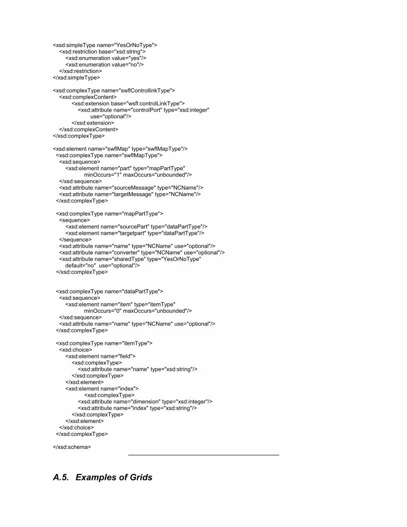
<xsd:simpleType name="YesOrNoType"> <xsd:restriction base="xsd:string"> <xsd:enumeration value="yes"/> <xsd:enumeration value="no"/> </xsd:restriction> </xsd:simpleType> <xsd:complexType name="swflControllinkType"> <xsd:complexContent> <xsd:extension base="wsfl:controlLinkType"> <xsd:attribute name="controlPort" type="xsd:integer" use="optional"/> </xsd:extension> </xsd:complexContent> </xsd:complexType> <xsd:element name="swflMap" type="swflMapType"/> <xsd:complexType name="swflMapType"> <xsd:sequence> <xsd:element name="part" type="mapPartType" minOccurs="1" maxOccurs="unbounded"/> </xsd:sequence> <xsd:attribute name="sourceMessage" type="NCName"/> <xsd:attribute name="targetMessage" type="NCName"/> </xsd:complexType> <xsd:complexType name="mapPartType"> <sequence> <xsd:element name="sourcePart" type="dataPartType"/> <xsd:element name="targetpart" type="dataPartType"/> </sequence> <xsd:attribute name="name" type="NCName" use="optional"/> <xsd:attribute name="converter" type="NCName" use="optional"/> <xsd:attribute name="sharedType" type="YesOrNoType" default="no" use="optional"/> </xsd:complexType> <xsd:complexType name="dataPartType"> <xsd:sequence> <xsd:element name="item" type="itemType" minOccurs="0" maxOccurs="unbounded"/> </xsd:sequence> <xsd:attribute name="name" type="NCName" use="optional"/> </xsd:complexType> <xsd:complexType name="itemType"> <xsd:choice> <xsd:element name="field"> <xsd:complexType> <xsd:attribute name="name" type="xsd:string"/> </xsd:complexType> </xsd:element> <xsd:element name="index"> <xsd:complexType> <xsd:attribute name="dimension" type="xsd:integer"/> <xsd:attribute name="index" type="xsd:string"/> </xsd:complexType> </xsd:element> </xsd:choice> </xsd:complexType> </xsd:schema>
A.5. Examples of Grids

A.5.1 Industrial Grids A.5.1.1 DAME (Jim Austin, York University) The theme of DAME project is the design and implementation of a fault diagnosis and prognosis system based on the Grid computing paradigm and the deployment of Grid services. In particular DAME focuses on developing an improved computer-based fault diagnosis and prognostic capability and integrating that capability with a predictive maintenance system in the context of aero-engine maintenance. The term “predictive maintenance” implies that there is sufficient time interval between the detection of a behaviour that departs from normal and the actual occurrence of a failure. The DAME system will deploy Grid services within this time window to develop a diagnosis of why an engine has deviated from normal behaviour, to provide prognosis (understanding what will happen) and to plan remedial actions that may be taken a safe and convenient point when the impact of maintenance is minimized. A central challenge of the project is to develop a proof of concept demonstrator that will address the commercial and technical requirements of the industrial partners within the consortium (Rolls-Royce and Data Systems & Solutions). The commercial considerations of the project create a set of demanding technical requirements which will be addressed through Grid computing techniques. These include:
Transmission of high volumes of data from remote data repositories, to and from the maintenance points; Access to highly specialised data analysis and diagnosis software services; Necessity to search extremely large volumes of data. Virtual Organisations (VO) where the various members are located in various parts of the world and where
complex interactions among multiple agents or stakeholders are needed and are facilitated by connection through the Grid
The need to provide supporting or qualifying evidence for the diagnosis or prognosis offered; Addressing the business critical aspects of the commercial deployment, developing a Grid enabled system that can
meet stringent dependability requirements, including Quality of Service and Security issues.
A.5.1.2 Geodise (Simon Cox, Southampton University) Engineering design search and optimisation is the process whereby engineering modelling and analysis are exploited to yield improved designs. Intelligent search tools will become a vital component of all engineering design systems and will steer the user through the process of setting up, executing and post-processing design search and optimisation activities. Such systems typically require large-scale distributed simulations to be coupled with tools to describe and modify designs using information from a knowledge base. These tools are usually physically distributed and under the control of multiple elements in the supply chain. Whilst evaluation of a single design may require the analysis of gigabytes of data, to improve the process of design can require assimilation of terabytes of distributed data. Achieving the latter goal will lead to the development of intelligent search tools. The focus of the Geodise project is on the use of computational fluid dynamics with BAE Systems, Rolls Royce, and Fluent (world leading developers of CFD codes). Geodise is being developed by the Universities of Southampton, Oxford and Manchester in collaboration with other industrial partners working in the domains of hardware (Intel), software (Microsoft), systems integration (Compusys), knowledge technologies (Epistemics), and grid-middleware (Condor). In summary, design optimisation needs integrated services
• Design improvements driven by CAD tools coupled to advanced analysis codes (CFD, FEA, CEM etc.) • On demand heterogeneous distributed computing and data spread across companies and time zones. • Optimization “for the masses” alongside manual search as part of a problem solving environment. • Knowledge based tools for advice and control of process as well as product.
Geodise will provide grid-based seamless access to an intelligent knowledge repository, a state-of-the-art collection of optimisation and search tools, industrial strength analysis codes, and distributed computing and data resources.
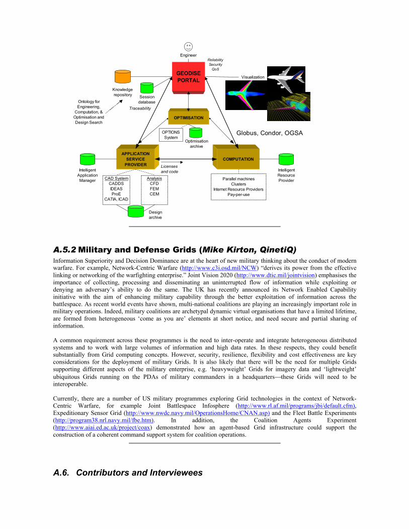
APPLICATION SERVICE
PROVIDERCOMPUTATION
GEODISE PORTAL
OPTIMISATION
Engineer
Parallel machinesClusters
Internet Resource ProvidersPay-per-use
Optimisation archive
Intelligent Application Manager
Intelligent Resource Provider
Licenses and code
Session database
Design archive
OPTIONSSystem
Knowledge repository
Traceability
Visualization
Globus, Condor, OGSA
Ontology for Engineering,
Computation, &Optimisation and Design Search
CAD SystemCADDSIDEASProE
CATIA, ICAD
AnalysisCFDFEMCEM
ReliabilitySecurity
QoS
A.5.2 Military and Defense Grids (Mike Kirton, QinetiQ) Information Superiority and Decision Dominance are at the heart of new military thinking about the conduct of modern warfare. For example, Network-Centric Warfare (http://www.c3i.osd.mil/NCW) “derives its power from the effective linking or networking of the warfighting enterprise.” Joint Vision 2020 (http://www.dtic.mil/jointvision) emphasises the importance of collecting, processing and disseminating an uninterrupted flow of information while exploiting or denying an adversary’s ability to do the same. The UK has recently announced its Network Enabled Capability initiative with the aim of enhancing military capability through the better exploitation of information across the battlespace. As recent world events have shown, multi-national coalitions are playing an increasingly important role in military operations. Indeed, military coalitions are archetypal dynamic virtual organisations that have a limited lifetime, are formed from heterogeneous ‘come as you are’ elements at short notice, and need secure and partial sharing of information. A common requirement across these programmes is the need to inter-operate and integrate heterogeneous distributed systems and to work with large volumes of information and high data rates. In these respects, they could benefit substantially from Grid computing concepts. However, security, resilience, flexibility and cost effectiveness are key considerations for the deployment of military Grids. It is also likely that there will be the need for multiple Grids supporting different aspects of the military enterprise, e.g. ‘heavyweight’ Grids for imagery data and ‘lightweight’ ubiquitous Grids running on the PDAs of military commanders in a headquartersthese Grids will need to be interoperable. Currently, there are a number of US military programmes exploring Grid technologies in the context of Network-Centric Warfare, for example Joint Battlespace Infosphere (http://www.rl.af.mil/programs/jbi/default.cfm), Expeditionary Sensor Grid (http://www.nwdc.navy.mil/OperationsHome/CNAN.asp) and the Fleet Battle Experiments (http://program38.nrl.navy.mil/fbe.htm). In addition, the Coalition Agents Experiment (http://www.aiai.ed.ac.uk/project/coax) demonstrated how an agent-based Grid infrastructure could support the construction of a coherent command support system for coalition operations.
A.6. Contributors and Interviewees

Name Organisation Projects
Stuart Anderson National e-Science Centre
Malcolm Atkinson National e-Science Centre
Jim Austin York University DAME
Dave Berry National e-Science Centre
Martin Berzins Leeds University
Gordon Blair Lancaster University
Chris Booth QinetiQ
David Boyd Rutherford-Appleton Laboratory
Ken Brodlie Leeds University gViz
John Brooke Manchester Computing myGrid, RealityGrid, GRIP, EuroGrid
Ray Browne DTI
Stephen Burke Rutherford-Appleton Laboratory GridPP
Graham Cameron EBI
Howard Chivers York University
Peter Clarke UCL GridPP
David Colling Imperial College GridPP
Geoffrey Coulson Lancaster University
Simon Cox University of Southampton GEODISE
Linda Cornwall Rutherford-Appleton Laboratory GridPP
Jon Crowcroft Cambridge University GridProbe, FutureGrid
Vijay Dialani University of Southampton
John Darlington Imperial College ICENI
David de Roure University of Southampton
Andrew Dean IBM Hursley
Peter Dew Leeds University DAME
Karim Djemame Leeds University
Matthew Dovey Oxford e-Science Centre e-Diamond, BioSimGrid
Alistair Dunlop Capital radio Group
Steven Fisher Rutherford-Appleton Laboratory GridPP
Martin Fletcher York University DAME
David Foster CERN
Moustafa Ghanem Imperial College DiscoveryNet
Alex Gray Cardiff University Grid1D, GridLab, GRAB, BD-World
Yike Guo Imperial College DiscoveryNet
Tony Hey EPSRC
Yan Huang Cardiff University JISGA
Alexander Holt University of Edinburgh GridPP
Richard Hughes-Jones University of Manchester GridPP
David Hutchison Lancaster University
Carole Goble University of Manchester myGrid
John Gordon Rutherford-Appleton Laboratory GridPP

Keith Haines University of Reading Godiva
Mark Hayes Cambridge e-Science Centre
Andrew Herbert Microsoft
Jon Hillier Oxford e-Science Centre
Tom Jackson York University DAME
Mark Jessop York University DAME
Andrew Keane University of Southampton GEODISE
Mike Kirton QinetiQ
Kerstin Kleese Daresbury Laboratory CLRC DataPortal, e-Minerals, NERC DataGrid, SRB
Bryan Lawrence Rutherford-Appleton Laboratory NERC DataGrid
Tony Linde University of Leicester AstroGrid
John MacLaren University of Manchester Market for Computational Services, Grenade
John Manley HP Labs, Bristol
Gavin McCance University of Glasgow GridPP
John McDermid York University
Andrew McNab University of Manchester GridPP
Robin Middleton Rutherford-Appleton Laboratory GridPP
Alistair Mills Rutherford-Appleton Laboratory
Luc Moreau University of Southampton myGrid, Comb-e-Chem
Steven Newhouse Imperial College ICENI
Keith Noddle University of Leicester AstroGrid
Savas Parastratidis Newcastle University
Norman Paton University of Manchester OGSA-DAI, MyGrid, BioQuery
Stephen Pickles Manchester Computing RealityGrid
Omer Rana Cardiff University Grid1D, GridLab
Guy Rixon University of Cambridge AstroGrid
Les Robertson CERN
Alan Robinson EBI
Lakshmi Sastry Rutherford-Appleton Laboratory GAPtk
B. Sathyaprakash Cardiff University Grid1D, GridLab
Nigel Shadbolt University of Southampton
Ian Sommerville Lancaster University
David Snelling
Mike Surridge IT Innovation myGrid, Comb-e-Chem
Tony Storey IBM Hursley
Ian Taylor Cardiff University Grid1D, GridLab
Anne Trefethen EPSRC/DTI
Martin Trotter IBM Hursley
David Watson IBM Hursley
Paul Watson Newcastle University MyGrid, OGSA-DAI
David Williams CERN
Jason Wood Leeds University gViz
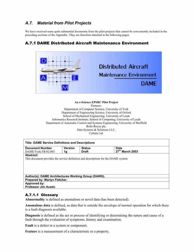
A.7. Material from Pilot Projects We have received some quite substantial documents from the pilot projects that cannot be conveniently included in the preceding sections of the Appendix. They are therefore attached in the following pages.
A.7.1 DAME Distributed Aircraft Maintenance Environment
An e-Science EPSRC Pilot Project Partners:
Department of Computer Science, University of York Department of Engineering Science, University of Oxford School of Mechanical Engineering, University of Leeds
Informatics Research Institute, School of Computing, University of Leeds Department of Automatic Control and Systems Engineering, University of Sheffield
Rolls-Royce plc. Data Systems & Solutions LLC.
Cybula Ltd.
Title: DAME Service Definitions and Descriptions
Document Number DAME/York/TR/02.005
Version 1g
Status Draft
Date 27th March 2003
Abstract: This document provides the service definition and descriptions for the DAME system.
Author(s): DAME Architectures Working Group (DAWG). Prepared by: Martyn Fletcher. Approved by: Professor Jim Austin A.7.1.1 Glossary Abnormality is defined as anomalous or novel data (has been detected).
Anomalous data is defined, as data that is outside the envelope of normal operation for which there is a fault diagnosis available.
Diagnosis is defined as the act or process of identifying or determining the nature and cause of a fault through the evaluation of symptoms, history and examination.
Fault is a defect in a system or component.
Feature is a measurement of a characteristic or a property.
Feature Vector is a measure of a set of n features in n-dimensional feature space.
Goal is the primary actor’s goal.
Involved Actor is an actor who is involved - but it is not clear at the point of reference whether the actor is a primary actor.
Main Success Scenario (MSS) is the scenario when everything goes to plan i.e. nothing goes wrong.
Novel data is defined as data that is outside the envelope of normal operation but no fault diagnosis is available.
Primary Actor is a stakeholder that calls on the system to deliver a service. The primary actor has a goal with respect to the system one that can be satisfied by its operation. The primary actor often triggers the use case but not always!
Prognosis is defined as a prediction of the probable course of an emerging fault through the evaluation of early symptoms.
Scenario is a “sequence” of behavioural steps (actions and interactions). The term “sequence” is used loosely because notes may be added to show that certain steps may be performed in parallel, in different orders, repetitively or as an option.
Stakeholder is someone or something that has a vested interest in the behaviour of the use case. Some stakeholders do not appear directly in the operation of the system e.g. owner of the company.
Supporting Actor is an external actor that provides a service to the system. An actor can be primary in one use case and supporting in another.
Symptom is a characteristic sign or indication of the existence of a condition. In the context of this document the indication will usually be the fact that a feature, group of features or feature vector has exceeded a threshold indicating the occurrence of a fault condition.
Threshold is a measurement point applied to a feature or feature vector. In the context of this document a feature or feature vector that exceeds a threshold is either a symptom or contributory towards a symptom.
Use Case describes the system’s behaviour under various conditions as the system responds to a request usually from the primary actor for the use case. A use case either meets the goal or fails in some way. (A use case is collection of successful and failure scenarios).
Major maintenance is defined as maintenance that would extend the turn round time beyond the specified period.
Minor maintenance is defined as maintenance that can be performed within the normal turn round time (this may be as short as 35 minutes in some cases).
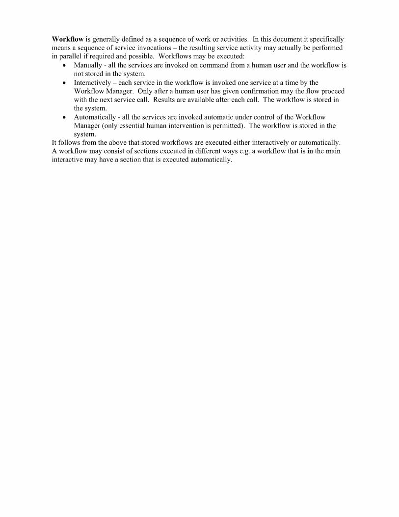
Workflow is generally defined as a sequence of work or activities. In this document it specifically means a sequence of service invocations – the resulting service activity may actually be performed in parallel if required and possible. Workflows may be executed:
• Manually - all the services are invoked on command from a human user and the workflow is not stored in the system.
• Interactively – each service in the workflow is invoked one service at a time by the Workflow Manager. Only after a human user has given confirmation may the flow proceed with the next service call. Results are available after each call. The workflow is stored in the system.
• Automatically - all the services are invoked automatic under control of the Workflow Manager (only essential human intervention is permitted). The workflow is stored in the system.
It follows from the above that stored workflows are executed either interactively or automatically. A workflow may consist of sections executed in different ways e.g. a workflow that is in the main interactive may have a section that is executed automatically.
A.7.1.2 Acronyms AURA: Advanced Uncertain Reasoning Architecture developed by University of York and Cybula.
CBR: Case Based Reasoning.
EDC: DS&S Engine Data Center.
ERS: DS&S Engine Records Service.
FHA: Fleet Hour Agreement – a business model where the customer purchases fleet hours e.g. “power by the hour”.
GSS: Ground Support System – the ground based part of the QUOTE system.
MRO: Maintenance, Repair & Overhaul – an internal company facility providing maintenance, repair & overhaul of engines off the aircraft.
MSS
SUD: System Under Design.
SDM: Rolls-Royce Service Data Manager.
TCP: Total Care Package – a business model where the customer purchases a complete service package rather than a physical asset e.g. an engine.
R&O: Repair and Overhaul.
TRT: Turn Round Time.
XTO: Extract Tracked Order.

A.7.1.3 Introduction This document outlines the service architecture to be provided by the DAME system. The service architecture is presented first, followed by example workflows for the major DAME use cases and then the top-level services are identified. A.7.1.4 Purpose and Scope The aim of the DAME project is to build a GRID test bed for generic Distributed Diagnostics. The application demonstrator for the test bed will involve the analysis of data generated from aircraft engines to identify potential faults that require maintenance. The main deliverables from the project will be:
1. A generic Distributed Diagnostics Grid Test Bed. 2. An Aero-gas turbine Application Demonstrator supporting aircraft engine diagnostics and first line
maintainer/aircraft dispatcher decision support. 3. Techniques for distributed data mining, diagnostics, and evaluation of the effectiveness of Globus etc for the
task. The purpose of this document is to provide the DAME service definitions and descriptions i.e. application design - identified in the DAME Software Methodology (see reference 1). The previous documents that lead up to this document are: DAME Initial requirements for the first demonstrator prototype (reference 2), DAME Requirements: Use cases (see reference 3) and the DAME Software Architecture (see reference 4). Other documents that will affect the detailed design are DAME Security Rationale, DAME Real-time Rationale and DAME Dependability Rationale (see references 5, 6 and 7).
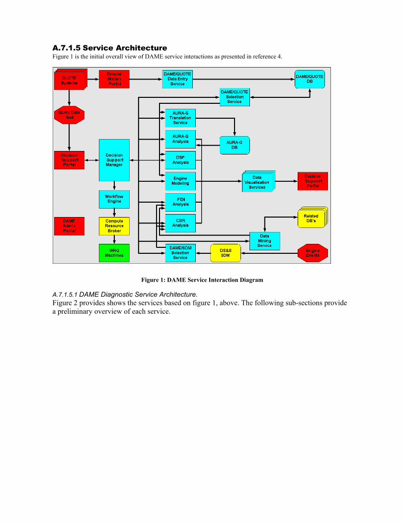
A.7.1.5 Service Architecture Figure 1 is the initial overall view of DAME service interactions as presented in reference 4.
Figure 1: DAME Service Interaction Diagram A.7.1.5.1 DAME Diagnostic Service Architecture. Figure 2 provides shows the services based on figure 1, above. The following sub-sections provide a preliminary overview of each service.
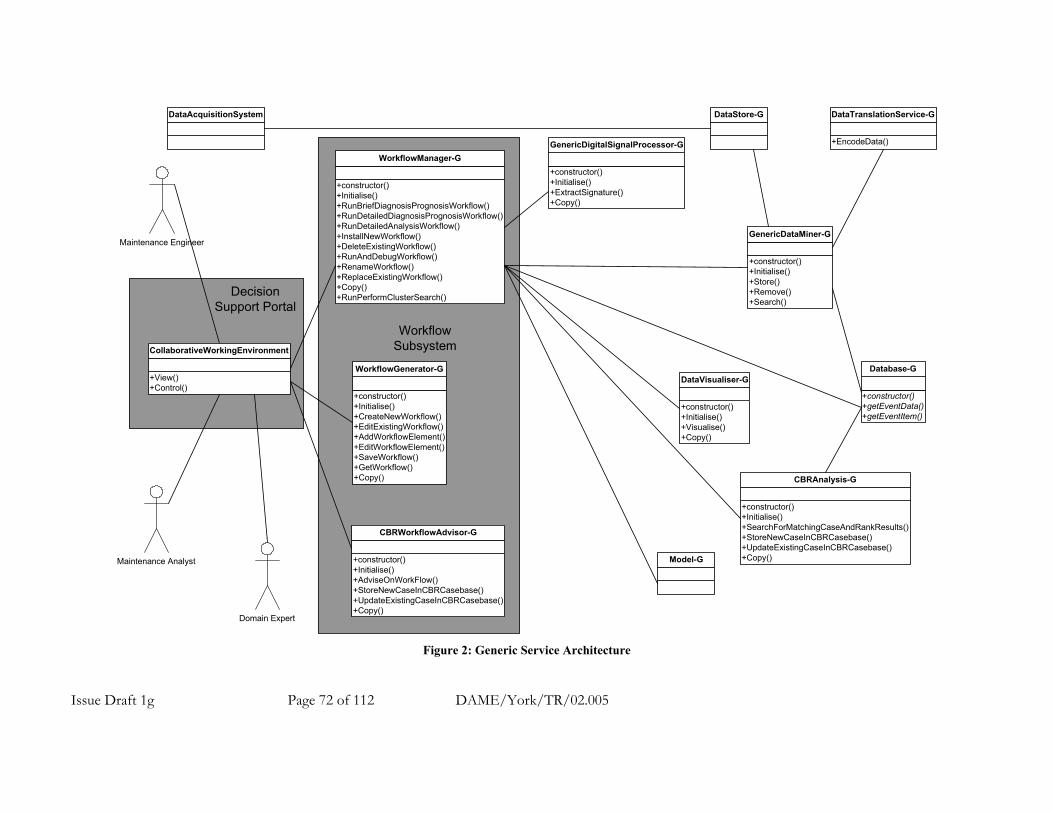
Issue Draft 1g Page 72 of 112 DAME/York/TR/02.005
+constructor()+Initialise()+RunBriefDiagnosisPrognosisWorkflow()+RunDetailedDiagnosisPrognosisWorkflow()+RunDetailedAnalysisWorkflow()+InstallNewWorkflow()+DeleteExistingWorkflow()+RunAndDebugWorkflow()+RenameWorkflow()+ReplaceExistingWorkflow()+Copy()+RunPerformClusterSearch()
WorkflowManager-G
+constructor()+Initialise()+CreateNewWorkflow()+EditExistingWorkflow()+AddWorkflowElement()+EditWorkflowElement()+SaveWorkflow()+GetWorkflow()+Copy()
WorkflowGenerator-G
+constructor()+Initialise()+SearchForMatchingCaseAndRankResults()+StoreNewCaseInCBRCasebase()+UpdateExistingCaseInCBRCasebase()+Copy()
CBRAnalysis-G
+constructor()+Initialise()+AdviseOnWorkFlow()+StoreNewCaseInCBRCasebase()+UpdateExistingCaseInCBRCasebase()+Copy()
CBRWorkflowAdvisor-G
Domain Expert
Maintenance Analyst
Maintenance Engineer
+constructor()+Initialise()+ExtractSignature()+Copy()
GenericDigitalSignalProcessor-G
DataAcquisitionSystem DataStore-G
+constructor()+Initialise()+Visualise()+Copy()
DataVisualiser-G
+constructor()+Initialise()+Store()+Remove()+Search()
GenericDataMiner-G
+constructor()+getEventData()+getEventItem()
Database-G
WorkflowSubsystem
Model-G
+EncodeData()
DataTranslationService-G
+View()+Control()
CollaborativeWorkingEnvironment
DecisionSupport Portal
Figure 2: Generic Service Architecture
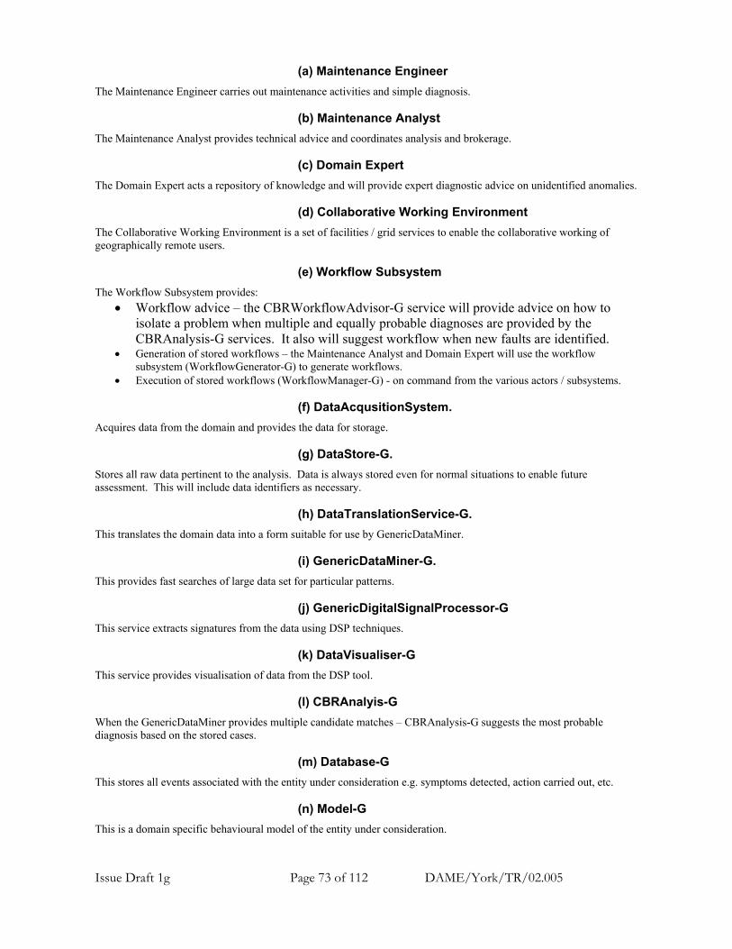
Issue Draft 1g Page 73 of 112 DAME/York/TR/02.005
(a) Maintenance Engineer The Maintenance Engineer carries out maintenance activities and simple diagnosis.
(b) Maintenance Analyst The Maintenance Analyst provides technical advice and coordinates analysis and brokerage.
(c) Domain Expert The Domain Expert acts a repository of knowledge and will provide expert diagnostic advice on unidentified anomalies.
(d) Collaborative Working Environment The Collaborative Working Environment is a set of facilities / grid services to enable the collaborative working of geographically remote users.
(e) Workflow Subsystem The Workflow Subsystem provides:
• Workflow advice – the CBRWorkflowAdvisor-G service will provide advice on how to isolate a problem when multiple and equally probable diagnoses are provided by the CBRAnalysis-G services. It also will suggest workflow when new faults are identified.
• Generation of stored workflows – the Maintenance Analyst and Domain Expert will use the workflow subsystem (WorkflowGenerator-G) to generate workflows.
• Execution of stored workflows (WorkflowManager-G) - on command from the various actors / subsystems.
(f) DataAcqusitionSystem. Acquires data from the domain and provides the data for storage.
(g) DataStore-G. Stores all raw data pertinent to the analysis. Data is always stored even for normal situations to enable future assessment. This will include data identifiers as necessary.
(h) DataTranslationService-G. This translates the domain data into a form suitable for use by GenericDataMiner.
(i) GenericDataMiner-G. This provides fast searches of large data set for particular patterns.
(j) GenericDigitalSignalProcessor-G This service extracts signatures from the data using DSP techniques.
(k) DataVisualiser-G This service provides visualisation of data from the DSP tool.
(l) CBRAnalyis-G When the GenericDataMiner provides multiple candidate matches – CBRAnalysis-G suggests the most probable diagnosis based on the stored cases.
(m) Database-G This stores all events associated with the entity under consideration e.g. symptoms detected, action carried out, etc.
(n) Model-G This is a domain specific behavioural model of the entity under consideration.

Issue Draft 1g Page 74 of 112 DAME/York/TR/02.005
A.7.1.5.2 DAME Diagnostic Demonstration Service Architecture. This section shows the previous architecture adapted for the DAME demonstration, in terms of:
• Identification of real services that will be used in the DAME demonstration e.g. generic AURA-G as the GenericDataMiner.
• The use of the services for engine diagnosis. Figure 3 shows the DAME demonstration service architecture and the following sections describe the various parts in more detail.

Issue Draft 1g Page 75 of 112 DAME/York/TR/02.005
WorkflowSubsystem
+constructor()+Initialise()+Store()+Remove()+Search()
AURA-G
+constructor()+Initialise()+SearchForMatchingCaseAndRankResults()+StoreNewCaseInCBRCasebase()+UpdateExistingCaseInCBRCasebase()+Copy()
CBRAnalysis-G
+constructor()+Initialise()+ModelEnginePerformance()+Copy()
EngineModel-G
+constructor()+Initialise()+RunBriefDiagnosisPrognosisWorkflow()+RunDetailedDiagnosisPrognosisWorkflow()+RunDetailedAnalysisWorkflow()+InstallNewWorkflow()+DeleteExistingWorkflow()+RunAndDebugWorkflow()+RenameWorkflow()+ReplaceExistingWorkflow()+Copy()+RunPerformClusterSearch()
WorkflowManager-G
+SDMSource()+getEventData()+getEventItem()+getEventAircraft()+getEventEngine()+getEventFromSerialDate()
SDM-G
+constructor()+Initialise()+StoreDataRecord()+RetrieveDataRecord()+Copy()
EngineDataStore-G
+constructor()+Initialise()+CreateNewWorkflow()+EditExistingWorkflow()+AddWorkflowElement()+EditWorkflowElement()+SaveWorkflow()+GetWorkflow()+Copy()
WorkflowGenerator-G
+constructor()+Initialise()+XTO()+JChart()+Copy()+InstallNewAlgorithm()+RunAndDebugAlgorithm()
XTO-G
QUOTE / GSS
Domain Expert
Maintenance Engineer
+constructor()+Initialise()+AdviseOnWorkFlow()+StoreNewCaseInCBRCasebase()+UpdateExistingCaseInCBRCasebase()+Copy()
CBRWorkflowAdvisor-G
+constructor()+Initialise()+Visualise()+Copy()
XTOOutputDataVisualiser-G
+View()+Control()
CollaborativeWorkingEnvironment
Maintenance Analyst
DecisionSupport Portal
Figure 3: DAME Demonstration Service Architecture

Issue Draft 1g Page 76 of 112 DAME/York/TR/02.005
(a) Collaborative Working Environment Grid services to enable collaborative working of the various actors involved. This is currently the subject of a detailed assessment / survey (see references 8 and 9).
(b) Workflow Subsystem This subsystem provides for workflow definition and execution. This is currently the subject of a detailed assessment / survey (see references 10 and 11). The Workflow Subsystem also contains the CBRWorkflowAdvisor-G (see reference 12) to provide advice on:
• How to isolate a fault when multiple and equally probable diagnoses are provided by the CBRAnalysis-G services.
• The workflow to use when new faults are identified. The CBRWorkflowAdvisor-G contains a case base containing “cases” of:
• List of faults. • Any other relevant information to the “case” such as the aircraft identifier, date of flight, departure point,
destination. • Appropriate workflows.
(c) QUOTE / GSS.
This acquires data from the engine, performs an on engine diagnosis and provides the “raw” data for storage. This is an on engine version of XTO (see references 13 and 14)

Issue Draft 1g Page 77 of 112 DAME/York/TR/02.005
(d) EngineDataStore-G.
Data is stored for all engines on a per flight basis (see reference 15). Data is always stored irrespective of whether a QUOTE abnormality was detected. For each engine “run” this element stores a record whose contents include:
• All the raw vibration data. • All the raw performance data. • QUOTE anomaly or novelty – if detected. • Aircraft identifier. • Engine identifier. • Date of flight. • Flight departure point. • Flight destination point. • Pattern match results and CBRAnalysis-G results. • Possibly AURA-G encoded raw data.
Notes:
1. The reference to raw data above is that provided as an output from the QUOTE and the Ground Support System. The data is not raw sensor data but has been pre-processed into a Rolls Royce Zmod form. Each engine produces around 1MB for every 101 seconds of flight or 35.6 MB per engine per hour. Therefore, for each engine on an 8-hour flight, approximately 285MB of data will be produced.
2. The engine data store contains a history of all the above data pertaining to all engines under observation. 3. Other engine data e.g. maintenance events etc. will be stored in the Rolls-Royce Service Data Manager (SDM). 4. The engine data store may also contain sets of AURA encoded data. 5. The QUOTE diagnosis resides in this store rather than in any other database because it is related to engine
runs.
(e) AURA-G. This provides generic and fast matching facilities [Advanced Uncertain Reasoning Architecture – AURA] (see references 16,17, 18, 19 and 20). The data translation service shown in figure 2 has been amalgamated with the main AURA-G service in figure 3. The following is an example of how AURA-G may be used. To search a new “engine run” record for the occurrence of similarities with data from other engine runs. In order to do this the following steps are undertaken:
1. The generic AURA-G has been previously “taught” with the entire contents of the engine database (in encoded form).
2. Raw data from the new “engine run” is encoded appropriately and applied to AURA-G. 3. AURA-G provides a set of possible matches of the new data with previous data.
(f) XTO-G
The XTO-G services extracts tracked orders from the vibration data and provides useful diagnostic information. As an engine accelerates, the rotation frequency of the shafts increases and so does the frequency of the vibrations caused by the shafts. A tracked order is the amplitude of the vibration signal in a narrow frequency band centred on a harmonic of the rotation frequency of a shaft as it changes frequency. There are usually some harmonics present; though most of the energy in the vibration spectrum is concentrated in the fundamental tracked orders, these constitute the “vibration signature” of the engine. Departures from the normal or expected shapes of these tracked orders provide very useful diagnostic information, for example, for the identification of out-of-balance conditions (see reference 13 and 14).
(g) XTOOutputDataVisualiser-G This provides appropriate visualisation of the XTO output (see reference 21).
(h) CBRAnalysis-G When AURA-G pattern matching provides multiple candidate matches – CBRAnalysis-G suggests the most probable diagnosis based on the stored cases (see reference 22 and 23). The CBRAnalysis-G contains a case base containing “cases” of:
• List of symptoms - this will include feature identifier(s) and threshold(s). • Any other relevant information to the “case” such as the aircraft identifier, date of flight, departure point,
destination.
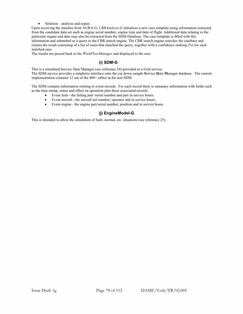
Issue Draft 1g Page 78 of 112 DAME/York/TR/02.005
• Solution – analysis and repair. Upon receiving the matches from AURA-G, CBRAnalysis-G initialises a new case template using information extracted from the candidate data set such as engine serial number, engine type and date of flight. Additional data relating to the particular engine and date may also be extracted from the SDM Database. The case template is filled with this information and submitted as a query to the CBR search engine. The CBR search engine searches the casebase and returns the result consisting of a list of cases that matched the query, together with a confidence ranking (%) for each matched case. The results are passed back to the WorkFlowManager and displayed to the user.
(i) SDM-G This is a simulated Service Data Manager (see reference 24) provided as a Grid service. The SDM service provides a simplistic interface onto the cut down sample Service Data Manager database. The current implementation contains 12 out of the 400+ tables in the real SDM. The SDM contains information relating to event records. For each record there is summary information with fields such as the time stamp, status and effect on operation plus these associated records:
• Event item - the failing part /serial number and part in service hours. • Event aircraft - the aircraft tail number, operator and in service hours. • Event engine - the engine part/serial number, position and in service hours.
(j) EngineModel-G
This is intended to allow the simulation of fault, normal, etc. situations (see reference 25).

Issue Draft 1g Page 79 of 112 DAME/York/TR/02.005
A.7.1.6 Main Use Cases and Example Workflows Each of the main DAME use cases defined in reference 3 is examined in this section and example workflows identified. The strategy taken is that the system will provide many diagnostic services that can be used as components in a workflow for different diagnostic scenarios. Example workflows for the main DAME use cases are provided in this section; however, the actual workflows used for each use case will be subject to refinement as the project progresses.
The intent is to provide a set of diagnostic services that may be used as appropriate in different workflows. Initially, the workflow for each use case may be subject to some experimentation and also it may be dependent on the previous stages i.e. contains branches. This versatility will be required in any generic diagnostic system and therefore should be considered in DAME.
Two new use cases have been identified i.e. “Generate Diagnostic Workflow Script” and “Develop New Detection Algorithm” and example workflows are provided.
The workflows that are currently active are installed and run from the Workflow Manager, however this is subject to assessment of the Workflow Subsystem (see references 10 and 11).
In this section example workflows are used to identify the required DAME services and should be considered from this standpoint. If it can be shown that one example workflow for a particular use case is not adequate to identify all the services required then multiple examples might be used for that use case.
Each workflow is described in terms of: Pre-conditions: The state of elements before the workflow is executed. Trigger: The event that triggers the workflow. Example Workflow: The workflow stages – each stage may represent several service calls at the moment. The workflow is also described as a UML sequence diagram. Post-Conditions: The state of elements after the workflow is executed.
It is assumed so far in this document that only one instance of each service exists – considerations of multiple instances are left out of this document at the moment.
Issue Draft 1g Page 80 of 112 DAME/York/TR/02.005
A.7.1.6.1 Example Workflow for New DAME Use Case: Generate Diagnostic Workflow Script The Maintenance Analyst and Domain Expert will be able to generate stored workflows using the WorkflowGenerator-G. The “Generate Stored Workflow” is a new use case not initially identified during use case study but it is necessary for generating different workflows.
The Maintenance Analyst (MA) is shown in figure 2 using the WorkflowGenerator-G to produce a new stored workflow and using the WorkflowManager-G to debug it. The Domain Expert could equally have been used in the example.
The workflow for “Generate Stored Workflow” is manually executed – controlled directly by the initiating actor (Maintenance Analyst or Domain Expert) i.e. it is not executed by the WorkflowManager-G. Pre-conditions.
1. New workflow is required. Workflow Trigger. The Maintenance Analyst or Domain Expert decides to create a new workflow. Example Workflow. The example flow (shown in figure 4) is listed below.
1. A workflow is created. The MA uses various services within the WorkflowGenerator-G – createWorkFlow(), addWorkflowElement(), editWorkflowElement(), saveWorkflow(), etc.
2. The new workflow is installed (possibly with a temporary name) in the WorkflowManager-G for debugging. The MA uses the installNewWorkflow() and the WorkflowManager-G uses getWorkflow().
3. The new workflow is then run and debugged within the WorkflowManager-G - The MA uses the runAndDebugWorkflow().
4. When the debug activity is successful (there may be further edits of the workflow needed) the new workflow replaces and existing one (delete and rename) or is left installed as an additional workflow.
Post-conditions. 1. A new workflow is available for use.
Notes:
1. The WorkflowManager-G and WorkflowGenerator-G be amalgamated – subject to the Workflow Subsystem survey.
2. Do we need another example to show the ability to record workflows?
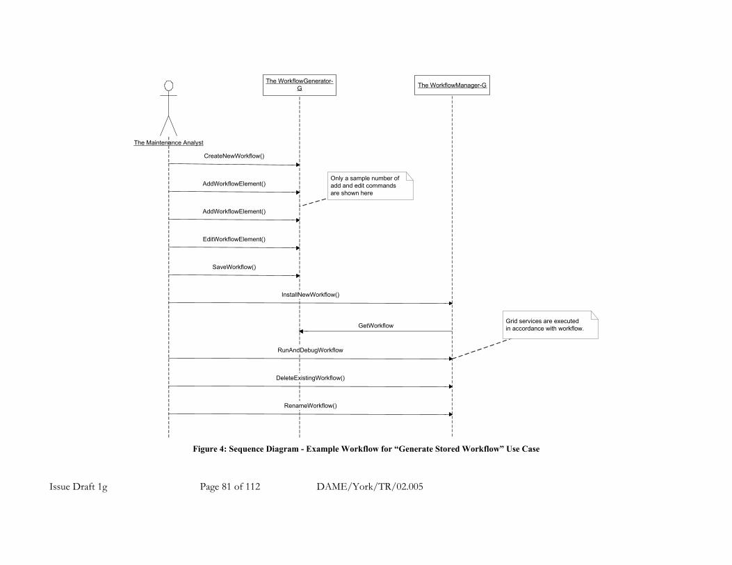
Issue Draft 1g Page 81 of 112 DAME/York/TR/02.005
The Maintenance Analyst
The WorkflowGenerator-G
CreateNewWorkflow()
The WorkflowManager-G
AddWorkflowElement()
EditWorkflowElement()
AddWorkflowElement()
SaveWorkflow()
InstallNewWorkflow()
RunAndDebugWorkflow
DeleteExistingWorkflow()
RenameWorkflow()
Grid services are executedin accordance with workflow.
Only a sample number ofadd and edit commandsare shown here
GetWorkflow
Figure 4: Sequence Diagram - Example Workflow for “Generate Stored Workflow” Use Case

Issue Draft 1g Page 82 of 112 DAME/York/TR/02.005
A.7.1.6.2 Example Workflow for DAME Use Case 1: Perform Brief Diagnosis / Prognosis This is a stored workflow that is always executed automatically by the WorkflowManager-G i.e. it is initiated automatically by a QUOTE data download then it proceeds and completes without any human intervention. The results are presented to Maintenance Engineer (ME) and are accessible by the Maintenance Analyst (MA) and Domain Expert (DE). The Maintenance Analyst (MA) and / or Domain Expert (DE) pre-define and test the workflow and service parameters – they may modify it in a controlled manner when necessary. The ME cannot modify the workflow or parameters in any way. Pre-conditions.
1. AURA-G has already been “taught” (been loaded with) the complete set of engine data from the EngineDataStore-G.
2. QUOTE transfers a new data record to engine data store (automatically). Workflow Trigger. The transfer of a new data record from QUOTE to the engine data store automatically triggers the workflow. Example Workflow. The example flow (shown in figure 5) is listed below.
1. AURA-G searches the complete set of historical data for matches with the new data. The WorkflowManager-G uses the AURA-G Search() service. AURA-G provides a list of matches. If no matches are found the workflow terminates at this point.
2. The CBRAnalysis-G provides diagnoses and ranks the results. The WorkflowManager-G uses the CBRAnalysis-G SearchForMatchingCasesAndRankResults() service.
3. The final result is returned to the Maintenance Engineer. Post-conditions.
1. The Maintenance Engineer (ME) has the final results – these and intermediate results are also accessible by the Maintenance Analyst (MA) and Domain Expert (DE).
Note:
1. All final and intermediate results are logged. 2. If the final result disagrees with the QUOTE diagnosis or is uncertain should the Maintenance Analyst be
informed automatically? 3. This workflow is protected – it cannot be deleted only replaced since the system must always have a resident
workflow for this use case. 4. The Maintenance Analyst may execute this workflow interactively for debugging purposes. The Maintenance
Engineer cannot execute it interactively.
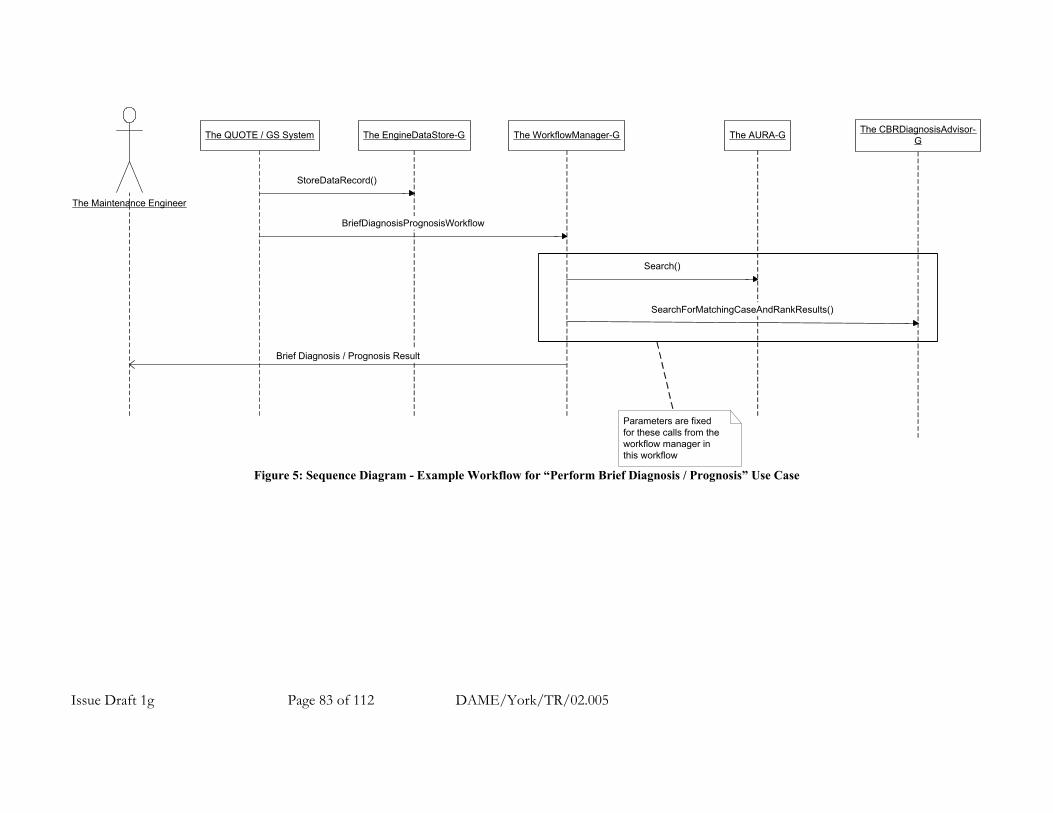
Issue Draft 1g Page 83 of 112 DAME/York/TR/02.005
The QUOTE / GS System The EngineDataStore-G The WorkflowManager-G The AURA-G The CBRDiagnosisAdvisor-G
The Maintenance Engineer
StoreDataRecord()
BriefDiagnosisPrognosisWorkflow
Search()
SearchForMatchingCaseAndRankResults()
Brief Diagnosis / Prognosis Result
Parameters are fixedfor these calls from theworkflow manager inthis workflow
Figure 5: Sequence Diagram - Example Workflow for “Perform Brief Diagnosis / Prognosis” Use Case

Issue Draft 1g Page 84 of 112 DAME/York/TR/02.005
A.7.1.6.3 Example Workflow for DAME Use Case 2: Perform Detailed Diagnosis / Prognosis This is a stored workflow. The WorkflowManager-G may execute this workflow in two modes: automatic and interactive as commanded by the Maintenance Analyst. The Maintenance Analyst (MA) may adjust the flow and parameters. The Maintenance Analyst (MA) receives the final and intermediate results. The Domain Expert may also access all results. Pre-conditions.
1. The workflow for use case 1 “Perform Brief Diagnosis / Prognosis” has been executed. 2. The CBRWorkflowAdvisor-G is aware of the result of any previous pattern matching activity because it is
stored in the raw data store in the data record. Workflow Trigger. The Maintenance Analyst (or Domain Expert) triggers the workflow. Example Workflow The example flow (shown in figure 6) is listed below. In interactive mode the workflow refers back to the Maintenance Analyst at each stage for parameters / confirmation before proceeding.
1. CBRWorkflowAdvisor-G provides the Maintenance Analyst with advice – assuming that use case 1 has already been performed. The WorkflowManager-G uses the CBRWorkflowAdvisor-G AdviseOnWorkFlow() service. This may be used to choose alternate sub workflows starting at step 3 below.
2. The Maintenance Analyst selects the appropriate sub workflow and may create or modify an existing workflow if necessary.
3. AURA-G searches the complete set of historical data for matches with the new data. The WorkflowManager-G uses the AURA-G Search() service. AURA-G provides a list of matches. If no matches are found the workflow terminates at this point.
4. The CBRAnalysis-G provides diagnoses and ranks the results. The WorkflowManager-G uses the CBRAnalysis-G SearchForMatchingCasesAndRankResults() service.
5. The result is returned to the Maintenance Analyst. Post-conditions.
1. The Maintenance Analyst (MA) has all the results – these are also accessible by the Domain Expert (DE). Note:
1. After running this use case the Maintenance Analyst considers the result and may run this use case again with different parameters before passing on the results.
2. Steps 3 to 4 are an interchangeable sub workflow.

Issue Draft 1g Page 85 of 112 DAME/York/TR/02.005
The WorkflowManager-G The AURA-G The CBRDiagnosisAdvisor-G
The Maintenance Analyst
RunDetailedDiagnosisPrognosisWorkflow()
Search()
Detailed Diagnosis / Prognosis Result
Parmeters may be providedby the Maintenance Analystto tune the operation.
This is an interchangeablesub workflow.Also the Maintenance Analystwill be able to select theparameters used in these callsfrom the Workflow Manager.
AURA-G and CBR-G Grid Servicescan be directly accessed by theMaintenance Analyst as necesary- without using theRunDetailedDiagnosisPrognoisisworkflow
SearchForMatchingCaseAndRankResults()
The CBRWorkflowAdvisor-G
AdviseOnWorkFlow()
Figure 6: Sequence Diagram - Example Workflow for “Perform Detailed Diagnosis / Prognosis” Use Case

Issue Draft 1g Page 86 of 112 DAME/York/TR/02.005
A.7.1.6.4 Example Workflow for DAME Use Case 3: Perform Detailed Analysis This is a manual workflow with stored sections where necessary for execution interactively or automatically. The Domain Expert (DE) may access all services directly and use full scope of engine model. Pre-conditions.
1. The workflow for use case 1 “Perform Brief Diagnosis / Prognosis” has been executed. 2. A workflow for use case 2 “Perform Detailed Diagnosis / Prognosis” has been executed. 3. The CBRWorkflowAdvisor-G is aware of the result of any previous pattern matching activity because it is
stored in the raw data store in the data record. Workflow Trigger. The Domain Expert triggers the workflow. Example Workflow The example flow (shown in figure 7) is listed below. In interactive mode the workflow refers back to the Domain Expert at each stage for parameters / confirmation before proceeding.
1. AURA-G searches the complete set of historical data for matches with the new problem data. The Domain Expert uses the AURA-G Search() service. AURA-G provides a list of matches.
2. The Domain Expert uses the EngineModel to investigate the problem using ModelEnginePerformance() call. 3. The Domain Expert may use the XTO-G services to investigate further. 4. The Domain Expert classifies the new fault. 5. The Domain Expert stores the new case advice for the fault in the CBRWorkflowAdvisor-G using the
StoreNewCaseInCBRDatabase() service. 6. The Domain Expert stores the new case diagnosis for the fault in the CBRAnalysis-G using the
StoreNewCaseInCBRDatabase() service. Post-conditions.
1. The Domain Expert (DE) has stored the new cases in the CBRWorkflowAdvisor-G. Note:
1. The Domain Expert considers result and may run this workflow again with different parameters before completing.
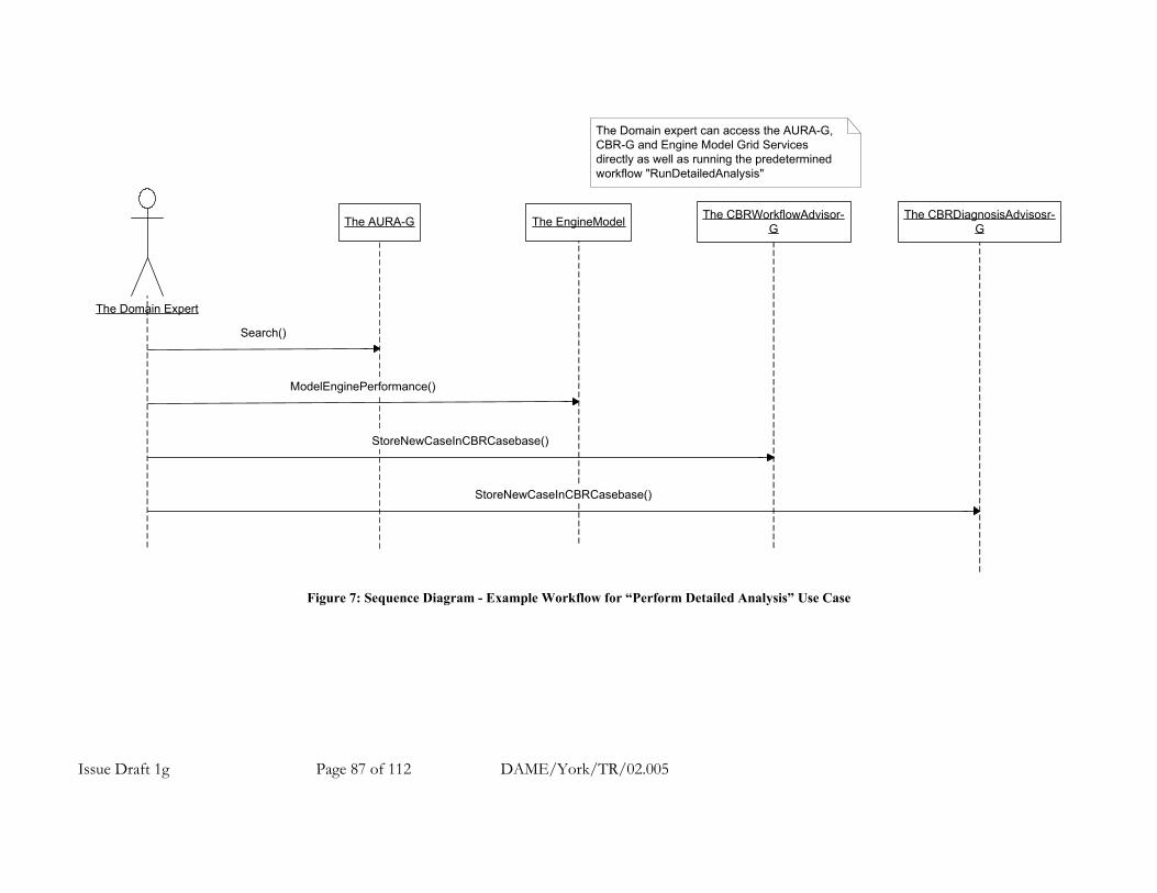
Issue Draft 1g Page 87 of 112 DAME/York/TR/02.005
The EngineModelThe AURA-G The CBRDiagnosisAdvisosr-G
The Domain Expert
ModelEnginePerformance()
Search()
StoreNewCaseInCBRCasebase()
The Domain expert can access the AURA-G,CBR-G and Engine Model Grid Servicesdirectly as well as running the predeterminedworkflow "RunDetailedAnalysis"
The CBRWorkflowAdvisor-G
StoreNewCaseInCBRCasebase()
Figure 7: Sequence Diagram - Example Workflow for “Perform Detailed Analysis” Use Case

Issue Draft 1g Page 88 of 112 DAME/York/TR/02.005
A.7.1.6.5 Example Workflow for DAME Use Case 4: Perform Cluster Search This is a stored workflow that may be executed interactively or automatically. The purpose of the use case is to search for clusters of problems to gain some insight into the causes. Raw data (from the EngineDataStore) or fault diagnosis data (from the SDM) may be used in the searched as described in the two example workflows. Pre-conditions. None. Workflow Trigger. The Maintenance Analyst (or Domain Expert) triggers the workflow. Example Workflow using raw data (searching for symptoms or pre-cursor) The example flow (shown in figure 8) is listed below. In interactive mode the workflow refers back to the Domain Expert at each stage for parameters / confirmation before proceeding.
1. The Maintenance Analyst (or Domain Expert) selects the appropriate search criteria. 2. The WorkflowManager-G uses AURA-G and the CBRAnalysis-G to compile statistics on the AURA-G
searches raw database for a feature specification or set of feature specifications. This stage is performed repetitively.
3. The WorkflowManager-G provides the statistics as results to the initiating actor. Example Workflow using SDM data (searching for diagnoses) The example flow (shown in figure 9) is listed below. In interactive mode the workflow refers back to the Domain Expert at each stage for parameters / confirmation before proceeding.
1. The Maintenance Analyst (or Domain Expert) selects the appropriate search criteria. 2. The WorkflowManager-G uses the SDM to search for fault diagnosis data according to the search criteria.
This stage is performed repetitively. Statistics on the searches are compiled. 3. The WorkflowManager-G provides the statistics as results to the initiating actor.
Post-conditions.
1. The Maintenance Analyst (and Domain Expert) has access to the compiled statistics. Note: The Maintenance Analyst considers result and may run this use case again with different parameters before passing on or acting on the results.

Issue Draft 1g Page 89 of 112 DAME/York/TR/02.005
The WorkflowManager-G The AURA-G The CBRDiagnosisAdvisor-G
The Maintenance Analyst
Search()
SearchForMatchingCaseAndRankResults()
result()
These calls are performedrepetitively under workflowmanager control.
RunPerformClusterSearch()
Figure 8: Sequence Diagram - Example Workflow using raw data for “Perform Cluster Search” Use Case

Issue Draft 1g Page 90 of 112 DAME/York/TR/02.005
The WorkflowManager-G
The Maintenance Analyst
Search
result
These calls are performedrepetitively under workflowmanager control.
RunPerformClusterSearch
The SDM
Figure 9: Sequence Diagram - Example Workflow using SDM data for “Perform Cluster Search” Use Case

Issue Draft 1g Page 91 of 112 DAME/York/TR/02.005
A.7.1.6.6 Example Workflow for New DAME Use Case: Develop New Detection Algorithm A new use case has been suggested for the development of DSP algorithms needed to quickly detect specific symptoms. This use case has yet to be documented fully in the Use Case document. The Domain Expert (DE) may access all services directly and use full scope of engine model. Pre-conditions.
1. A new fault and symptom has been classified and an algorithm for detection of the symptom is required? Workflow Trigger. The Domain Expert triggers the workflow. Example Workflow The example flow (shown in figure 10) is listed below.
1. The Domain Expert installs a new algorithm into the XTO-G services. 2. The Domain Expert runs the service and can debug the operation of the new algorithm on test data from the
EngineDataStore-G. Post-conditions.
1. The Domain Expert (DE) has results from the algorithm test. Note:
1. The Domain Expert considers result and may run this workflow again with modifications as necessary. 2. This will probably be a manual workflow but may later include stored sections where necessary for execution
interactively or automatically.

The Domain Expert
InstallNewAlgorithm()
The XTO-G
RunAndDebugAlgorithm()
This sequence may be performedmany times as the algorithm is modifiedand will need to access the EngineDataStorefor testing.
Figure 10: Sequence Diagram - Example Workflow for “Perform Detailed Analysis” Use Case
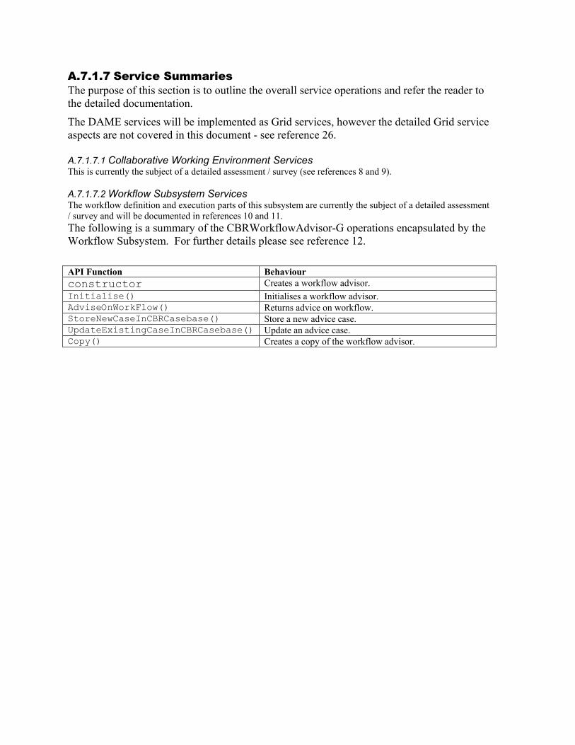
A.7.1.7 Service Summaries The purpose of this section is to outline the overall service operations and refer the reader to the detailed documentation.
The DAME services will be implemented as Grid services, however the detailed Grid service aspects are not covered in this document - see reference 26. A.7.1.7.1 Collaborative Working Environment Services This is currently the subject of a detailed assessment / survey (see references 8 and 9). A.7.1.7.2 Workflow Subsystem Services The workflow definition and execution parts of this subsystem are currently the subject of a detailed assessment / survey and will be documented in references 10 and 11. The following is a summary of the CBRWorkflowAdvisor-G operations encapsulated by the Workflow Subsystem. For further details please see reference 12.
API Function Behaviour constructor Creates a workflow advisor. Initialise() Initialises a workflow advisor. AdviseOnWorkFlow() Returns advice on workflow. StoreNewCaseInCBRCasebase() Store a new advice case. UpdateExistingCaseInCBRCasebase() Update an advice case. Copy() Creates a copy of the workflow advisor.

A.7.1.7.3 EngineDataStore-G Services The following is a summary of the EngineDataStore-G operations. For further details please see reference 15. API Function Behaviour constructor Creates an engine store service. Initialise() Initialises an engine store service. StoreDataRecord() Store a new data record (see below) from a newly arrived aircraft in
the EngineDataStore-G. RetrieveDataRecord() Retrieve a data record (see below) from the EngineDataStore-G. Copy() Creates a copy of the engine store. Description of a Data Record A data record is the data obtained from each QUOTE box irrespective of whether a QUOTE abnormality was detected. The data record will also include the QUOTE abnormality if detected, flight departure and destination points and is identified uniquely, possible with an identifier made up of the engine serial number and date. The following data fields are stored by this service in the raw data store:
• All the raw vibration data. • All the raw performance data. • QUOTE anomaly or novelty. • Aircraft identifier. • Engine identifier. • Date of flight. • Flight departure point. • Flight destination point. • A unique index (possible made up of some of the other identifiers – to allow the record for a particular
engine to be easily accessed?). • Duration of flight (flight time).
The following data fields are not stored by these services in the raw data store:
• Pattern match results and CBRAnalysis results. These data fields are stored as “null” by this service – the pattern matching and CBRAnalysis-G populate the data fields later. A.7.1.7.4 AURA-G Services The following is a summary of the AURA-G operations. For further details please see references 16, 17 and 18. The table below is taken from reference 16. API Function Behaviour Constructor Creates a search engine. Initialise() Initialises a search engine. Store() Stores binary patterns in the search engine. Remove() Removes binary patterns from the search engine. Search() Searches for matches to the input pattern provided.

A.7.1.7.5 XTO-G and XTOOutputDataVisualiser-G Services The following is a summary of the XTO-G and XTOOutputDataVisualiser-G operations. For further details please see references 14 and 21. API Function Behaviour Constructors summary Query() Creates a Query service. Xto() Creates an Xto service. Chart() Creates a Chart service. Methods summary SubmitQuery() Extracts the data sets available from within the existing database, depending on
the parameters selected such as engine serial number, day in the month (date), month and year when the test data was recorded.
SubmitJob() Submit the job to run the XTO analysis in order to analyse the data set selected from within the results of the SubmitQuery using a number of plug-ins (user have the option to select the desired plug-ins) and the a text/data output file will be generated with features corresponding to the selected plug-ins.
ShowChart() This reads in the data generated by SubmitJob (XTO) and displays the chart of the selected feature with given step size and in desired format (jpg, png) in the browser window.
WriteChart() This reads in the data generated by SubmitJob (XTO) and write the chart of the selected feature with given step size and in desired format (jpg, png) to the file.

A.7.1.7.6 CBRAnalysis-G Services The following is a summary of the CBRAnalysis-G operations. For further details please see reference 22.
API Function Behaviour constructor Creates a CBR analysis service. Initialise() Initialises a CBR analysis service. SearchForMatchingCaseAndRankResults() Returns advice on diagnosis. StoreNewCaseInCBRCasebase() Store a new diagnosis case. UpdateExistingCaseInCBRCasebase() Update a diagnosis case. Copy() Creates a copy of the CBR analysis service.

A.7.1.7.7 SDM-G Services The Simulated Service Data Manager (SDM) web service provides a simplistic interface onto the cut down sample Service Data Manager database (see reference 24). The current implementation contains 12 out of the 400+ tables in the real SDM. The SDM contains information relating to event records. For each record there is summary information with fields such as the time stamp, status and effect on operation plus these associated records:
• Event item - the failing part /serial number and part in service hours. • Event aircraft - the aircraft tail number, operator and in service hours. • Event engine - the engine part/serial number, position and in service hours.
The service implements an API that is given below to allow clients to extract event data of one of the above types for a given event. Currently the service use JDBC drivers to connect directly to the SDM database instance. Future implementations may use OGSA-DAI grid database services in place of the direct database connection.
Method Description SDMSource Service constructor.
eventData getEventData (int eventNumber) Get event information for a given event number.
eventItem getEventItem (int eventNumber) Get information about an item involved in a given event.
eventAircraft getEventAircraft (int eventNumber) Get aircraft information for a given event. eventEngine getEventEngine (int eventNumber) Get engine information for a given event.
int getEventFromSerialDate (int eventNumber) Find the event number that belongs to the given engine on the specified date.
A.7.1.7.8 EngineModel-G Services The following is a summary of the EngineModel-G operations. For further details please see reference 25.
API Function Behaviour constructor Creates an engine model service. Initialise() Initialises engine model service. ModelEnginePerformance() Returns results of the run. Copy() Creates a copy of the engine model.

A.7.1.8 References 1. DAME Software Methodology. September 2002. 2. DAME Initial requirements for first demonstrator prototype. 3rd May 2002 version 1.0. 3. DAME Requirements: Use Cases Version 1. 10th October 2002. DAME/York/TR/02.001. 4. DAME Software Architecture. DAME/Leeds/TR/02.03 5. DAME Security Rationale. 6. DAME Real-time Rationale. 7. DAME Dependability Rationale. 8. DAME Collaborative Working Environment Assessment / Survey. 9. DAME User Interface - Specification / User Guide / Programmer’s Reference Manual. 10. DAME Workflow Subsystem Assessment / Survey. 11. Workflow Subsystem Grid Services - Specification / User Guide / Programmer’s Reference Manual. 12. Case Based Reasoning (CBR) Workflow Advisor Grid Services - Specification / User Guide /
Programmer’s Reference Manual. 13. Hayton, Schölkopf, Tarassenko, and Anuzis. Support Vector Novelty Detection Applied to Jet Engine
Vibration Spectra (2000). NIPS. 14. XTO - Specification / User Guide / Programmer’s Reference Manual. 15. DAME Engine Data Store Services - Specification / User Guide / Programmer’s Reference Manual. 16. AURA Library - Specification. 27th January 2003. AURA/York/TR/02.003. 17. AURA Library - User Guide. 27th January 2003. AURA/York/TR/02.005. 18. AURA Library -. 27th January 2003. AURA/York/TR/02.006. 19. AURA Library - Performance Analysis. 27th January 2003. AURA/York/TR/02.008. 20. DAME Pattern Matching using AURA Rationale. 21. XTO Output Data Visualiser - Specification / User Guide / Programmer’s Reference Manual. 22. Case Based Reasoning (CBR) Analysis Grid Services - Specification / User Guide / Programmer’s
Reference Manual. 23. Background to CBR. DAME/Sheffield/TN/02.001 24. Simulated Service Data Manager (SDM) Services - Specification / User Guide / Programmer’s Reference
Manual? 25. Engine Model Services - Specification / User Guide / Programmer’s Reference Manual. 26. DAME Grid Service Implementation Guidelines.

A.7.2 Discovery Net: e-Science Service Delivery Roadmap April 2003 Prof. Yike Guo Dept. of Computing Imperial College A.7.2.1 Objectives The Discovery Net project is a 3-year pilot e-Science project that started in October 2002. During the first 18 months Discovery Net development efforts have concentrated on building the service-oriented grid-based infrastructure for knowledge discovery. The first prototype was demonstrated in Supercomputing 2002 where a discovery test bed for the life sciences was presented. This document provides the roadmap for the next 18 months of the Discovery Net project, where the development effort we will be concentrating on:
1. Application Services: We will deploy application demonstrators for the Discovery Net infrastructure for Knowledge Discovery. The application services will be published both:
i. Through a web portal for use by the UK e-Science community and ii. Through a Grid Service (OGSA).
These demonstrators will be based on fixed applications in the following areas: 1. Life science 2. Environmental Modelling 3. Scientific Literature Analysis
2. Service Composition Environment: We will also develop and provide an environment allowing end-user scientists and data analysts to compose their own Knowledge Discovery analysis workflows as a mechanism for service composition. These workflows will then be deployed as new application services.
3. Standards: We will publish the DPML (Discovery Process Markup Language) as a standard for
composing and deploying knowledge discovery processes. We will also make use of other standards and reference implementations emerging within the Grid community including OGSA-DAI for data access and integration.
4. International Collaborations: We are currently collaborating with various international
projects. Some have already expressed interest in using Discovery Net services as their preferred knowledge Discovery Platform. Discoevry Net will be provided to the collaborative projects as "service engine" that they can use for constructing their own knowledge discovery workflows, and used to extend the service by integrating their own services using the Discovery Net registration facility.

A.7.2.2 Application Services: A.7.2.2.1 Introduction The first set of application services delivered by Discovery Net will be targeted for specific domains. Three application areas have been selected from the Discovery Net portfolio, these are
• Life Sciences: where we will provide application services for 1. Gene Expression Analysis 2. DNA Sequence Annotation 3. Bio-IP Analysis with Built-in Ontology (we will explore the collaboration with
MyGrid project)
• Environmental Modelling: where we will provide an application for Air quality monitoring and analysis
• Scientific Literature Analysis: where we will provide an application for Automatic
Document Categorization The aim is to construct and deploy a series of application-oriented services that are useful for scientific researchers in the UK e-science community while allowing the Discovery Net team to collect feedback on and gain experience on how these users are actually accessing and using these services. For each of the demonstrator testbeds, the user will have access to domain-specific analysis components that execute on distributed servers. Initially, the services will be made available to the project consortium executing on Discovery Net resources. Then, they will be made available for wider access through selected e-Science centres.

A.7.2.2.2 Overview of Application Service Operation Environment Each service will be developed using the Discovery Net client by composing a knowledge discovery workflow that makes use of local and remote data sources, services and analysis components.
1. In the first instance these services will be deployed internally within the project consortium allowing our end-user partners to access them for evaluation and validation.
2. The application services will be scheduled and executed on Discovery Net Servers hosted within the Discovery Net project (the individual components in the workflows may execute remotely). These services will be accessed either through a web portal interface or as a grid service.
3. Each application service will be based on a widely used, but fixed distributed workflow (i.e.
using a set of distributed resources), that users can apply to their own data sets. The workflow will be constructed using the Discovery Net Client interface currently available only to the project consortium.
4. The portal interface for each application service is automatically generated from DPML
workflows using the Discovery Net Deployment System allowing customisation of the input/output of the workflow.
5. Users will login securely, choose an application service from the set of registered services,
upload and submit their data and the analysis results are returned to them.
6. Users will be allowed to parameterize application services through their associated portal interface where they can set parameters and properties (generated by the Discovery Net Deployment System ).
7. After internal validation, the service will be made available to the wider UK e-Science
community based on individual user/group registration.
Text Analysis
Clustering Classification
Gene function perdition
Homology SearchPromoter Prediction
Service Composition
Execution Environment
Text Analysis
Clustering Classification
Gene function perdition
Homology SearchPromoter Prediction
Service Composition
Execution Environment
A.7.2.3 Service Composition Environment The aim of the service composition environment is to provide users with the capability to construct their own application services by composing existing services through using workflows. To enable this, Discovery Net we will extend the existing infrastructure and toolset for constructing and deploying the workflows so that they can be accessed remotely as services. To this effect, the environment will have the following functions:
1. Workflow Construction, Storage and Execution 2. Workflow-based Service Registration and Deployment
Initially the environment will be made available to the project consortium. It will then be made available for wider access through selected e-Science centres. Access to the Discovery Net server will be implemented as a set of Grid Services (OGSA). A.7.2.3.1 Workflow Construction, Storage and Execution We will provide developers with:
1. Access to a library of knowledge discovery components on Discovery Net servers to act
as building blocks for workflow construction. These will include components for accessing relational and web-based data sources, web services and data processing and analysis.
2. Workflow Construction: Initially, the user will have access to the component composition
through the web-based interface where each component will be defined in terms of its input/output parameters. The tool will allow users to create workflows by connecting these components together and to set their parameters.
3. Workflow Verification: Discovery Net workflows are specified in DPML, which will be
published as a standard for constructing knowledge discovery workflows. The user may construct DPML workflows using other means, and submit these for verification.
4. Workflow Storage: allowing users to manage their own library of workflows, share
workflows within a community and providing workflow indexing and searching functionalities.
5. Workflow Execution: We will also provide the mechanisms for executing the specified
workflows and returning the results to the user. A.7.2.3.2 Workflow-based Service Registration and Deployment We will provide facilities for storing user workflows, and for deploying these workflows both as portals and new services that can later be used in other workflows.
1. Open Workflow: A WSDL Port type will be published for the integration of 3rd party web services within the workflows. We will allow users to register compliant web services within Discovery Net. This will allow users of the system to integrate their own data analysis components within workflows.

2. Data Access Integration: As one of the main issues in distributed data analysis is the transport of data from service to service, a standard representation is needed. We will investigate the OGSA-DAI approach2 and its potential use for the transfer over SOAP of large data sets.
3. Workflow Deployment: allowing users to transform a workflow into an application
service using the Discovery Net Deployment tool. These application services can be accessed through automatically generated portal interface, or through the Grid Service interface.
4. Application Service Registration: The various generated application services can be
registered so that end-users can lookup and retrieve them.
2 For instance, the use of Java WebRowSet, for which XML serialisation has been defined is used to transfer data to and from an external web service

A.7.2.4 Support for Service Construction InforSense Limited, as the industrial partner of the project, has been actively working with the project in commercializing the software research results of the project under an Intellectual Property transfer agreement with Imperial College. It is expected that InforSense will provide the necessary technical support of the core server software to enable the operation of the service after the project. We also expect some support from the research council will be provided for the operation of the service.
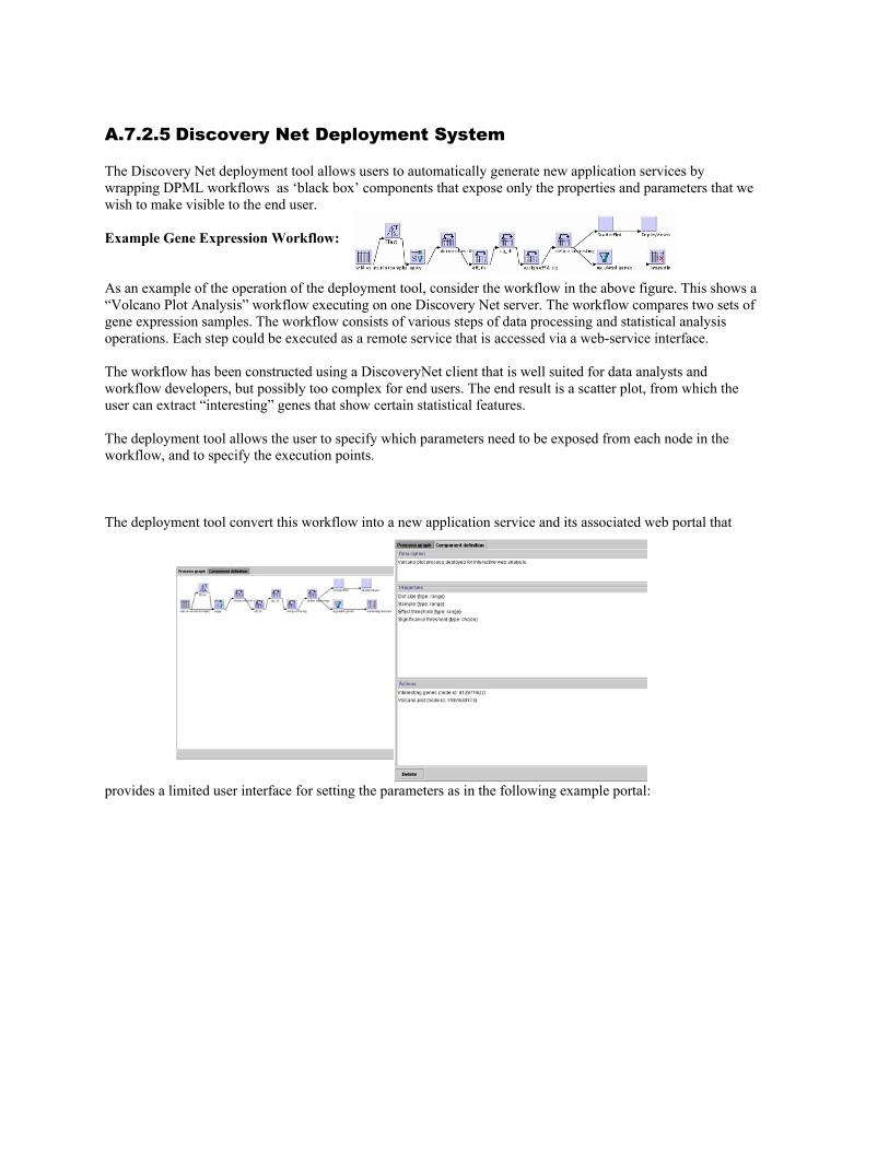
A.7.2.5 Discovery Net Deployment System The Discovery Net deployment tool allows users to automatically generate new application services by wrapping DPML workflows as ‘black box’ components that expose only the properties and parameters that we wish to make visible to the end user. Example Gene Expression Workflow:
As an example of the operation of the deployment tool, consider the workflow in the above figure. This shows a “Volcano Plot Analysis” workflow executing on one Discovery Net server. The workflow compares two sets of gene expression samples. The workflow consists of various steps of data processing and statistical analysis operations. Each step could be executed as a remote service that is accessed via a web-service interface. The workflow has been constructed using a DiscoveryNet client that is well suited for data analysts and workflow developers, but possibly too complex for end users. The end result is a scatter plot, from which the user can extract “interesting” genes that show certain statistical features. The deployment tool allows the user to specify which parameters need to be exposed from each node in the workflow, and to specify the execution points. The deployment tool convert this workflow into a new application service and its associated web portal that
provides a limited user interface for setting the parameters as in the following example portal:

The deployment tool effectively constructs a new super-node that can be deployed or that can be used in other workflows. The deployment tool will be used internally to generate the application services discussed in Section 2.
Properties
Actions
Result
PropertiesProperties
ActionsActions
ResultResult
A.7.2.6 DPML Discovery Process Markup Language Tasks composed in Discovery Net are defined in Discovery Process Markup Language (DPML). DPML is an XML-based language that describes processes as dataflow graphs mirroring the visual language used to compose the task. In addition to information needed for execution, users can annotate each operation with structured notes to describe the rationale behind the process. The authoring environment also records a history of how the process was constructed. As such, DPML represents a complete description of a discovery process including information for execution, reporting and audit. A DPML graph can be sent for execution to any Discovery Net server. The server may choose to execute nodes on other Discovery Net servers, and each node may also use external distributed resources. This distribution is transparent to the user and the DPML sent from the client. The result, or a proxy to the result in the case of data sets, is returned to the caller. DPML is planned for public release in May 2003. A draft of the current DPML definition is available on the Discovery Net web site.

A.7.3 myGrid myGrid Component Inventory
Document Class: Note Author: Nick Sharman Institution: University of Manchester Date: 2003-07-29 Pages: 115
A.7.3.1 Introduction This note describes the components (including clients, services, APIs and tools) that we expect to produce in the myGrid project. A.7.3.2 Generic e-Science Components A.7.3.2.1 Service Registry The myGrid Service Registry federates a set service registries of interest to a (virtual) organization. The federated registries may be general-purpose or specific to a particular (scientific) community. It is thus a single point of contact for service discovery for the virtual organization. The myGrid Service Registry supports the widely-used UDDI interface, extended by the ability to attach and retrieve additional metadata to service registrations and their elements (such as particular operations). The myGrid Service Registry allows its users to establish multiple views that provide access to a user-defined subset of the registered services. These views can be specific to individual scientists (thus supporting personalization) or to further, more specialized, discovery services. A.7.3.2.2 Semantic Service Discovery Service The myGrid Semantic Service Discovery Service is a specialized discovery service that establishes a view over the myGrid Service Registry to capture services that support a semantic annotation under some set of OWL ontologies. It allows its users to search for services that satisfy some concept expressed as an OWL expression. A.7.3.2.3 Service Ontology The myGrid Service Ontology is an OWL ontology that allows its users to describe Web and Grid services. For practical use, this ontology will need to be combined with one or more domain ontologies: the myGrid project will provide an initial bioinformatics/biology

A.7.3.2.4 Service Description & Publication Tool The myGrid Service Description & Publication Tool allows it users to construct semantic service descriptions in terms of some ontology and attach them to new or existing service registrations in the myGrid Service Registry. A.7.3.2.5 Notification Service The myGrid Notification Service is a general purpose topic-based publish-and-subscribe intermediary. It will be used in myGrid to support workflow progress monitoring and service registration and database update notifications. A.7.3.2.6 Workflow Enactment Service The myGrid Workflow Enactment Service supports the execution of e-Science processes as possibly long-running workflows. The service: • Captures an execution trace and intermediate results to create a record of provenance for its results • Allows the composed service providers to be discovered dynamically at execution time A.7.3.2.7 Workflow Editor The myGrid Workflow Editor is a tool that allows the graphical creation and modification of workflow definitions that can be executed by the myGrid Workflow Enactment Service. It serves as both a standalone tool and as a plugin for the myGrid e-Science Workbench. A.7.3.2.8 Information Repository The myGrid Information Repository manages the information (data & metadata) for an organization or organizational unit. The stored information is organized into projects and experiments. The myGrid Information Repository provides facilities similar to a networked filestore. However, all entities stored in the repository can be qualified by a semantic (OWL-based) concept and an indication of concrete format, and can be described and related by annotation objects that are themselves first-class entities. Other entity types recognized by the Repository include workflow definitions and provenance records. A.7.3.2.9 E-Science Gateway Service The myGrid e-Science Gateway Service provides applications with a unified API and point of access to an organization or organizational unit’s instances of the key myGrid services, including the Service Registry, Workflow Enactment Service and Information Repository. The clients of the tool can include domain-specific applications as well as generic e-Science applications such as the myGrid e-Science Workbench and e-Science Web Portal. A.7.3.2.10 E-Science Workbench The myGrid e-Science Workbench is a rich interactive tool (based on the NetBeans framework, www.netbeans.org) through which a scientist interacts with myGrid and other Web and Grid services and the data and metadata in the myGrid Information Repository via the e-Science Gateway Service. A.7.3.2.11 E-Science Web Portal The myGrid e-Science Web Portal is a less-capable alternative to the e-Science Workbench. It supports a subset of the Workbench’s functionality and can be used where remote access or a zero-footprint solution is useful (for example, via PDAs or mobile phones). A.7.3.2.12 Distributed Query Processing Service The myGrid Distributed Query Processing Service (developed jointly with the North-East Regional e-Science Centre) provides on OGSA-DAI-based interface that supports distributed queries over any SQL and ODMG OQL-capable data sources that themselves support the OGSA-DAI interface. In myGrid, it will be used to federate myGrid Information Repositories owned by members of a virtual organization, and to execute queries involving any collection of Information Repositories and domain-specific databases. A.7.3.2.13 E-Science Application Framework The myGrid e-Science Application Framework is a component model for flexible, simple and future-proof deployment and use of services on the Grid. It comprises: • A client-side API that allows clients to invoke services in a protocol-independent manner

• A server-side API that allows a business logic to be deployed according to different standards; our implementation is based on Enterprise Java Beans and we deploy services as Web Services, OGSA Grid Services and EJBs
• A nested container model allowing deployers to identify non-business-logic functionality that needs to be deployed in order to facilitate the integration of the service in virtual organizations
A.7.3.3 Bioinformatics-specific Components A.7.3.3.1 Bioinformatics Ontology The myGrid Bioinformatics Ontology, is an OWL ontology that, when composed with the myGrid Service Ontology, allows users to describe and discover services, workflows and data by their semantics. A.7.3.3.2 SOAPLAB SOAPLAB is a set of Web Services that provide programmatic access to applications on remote systems. Its interface is based on the OMG’s CORBA-based Biomolecular Sequence Analysis specification, and in myGrid is used to give access to bioinformatics applications such as the EMBOSS suite (see www.hgmp.mrc.ac.uk/Software/EMBOSS).
A.7.3.4 Miscellaneous Components A.7.3.4.1 AntMerge: build-file construction tool The myGrid project, like many other Java-based projects, uses Ant to execute reliable and reproducible component builds (see http://ant.apache.org). Ant’s build-files can be come complex, so to reduce the effort needed to develop and maintain robust build files over the myGrid component set, the project has developed a tool to compose build files from a suite of generic build file parts and a component-specific part.

A.7.4 The eDIKT Project and OGSA-DAI Rob Baxter, eDIKT project manager [eDIKT]. 25/03/2003 A.7.4.1 OGSA-DAI vs eDIKT::eldas There has been a lack of clarity in presentations of the complementary work of the OGSA-DAI project and the eDIKT::eldas project in implementing versions of OGSA-DAI. This memo seeks to redress this. The OGSA-DAI project is charged with defining OGSA-based standards for data access and integration, and with producing a production-quality reference implementation of the standard service components. The functional scope of OGSA-DAI has been defined in project deliverables and is quite wide, covering all aspects from GridDataServices through DataTransport to Registries. Because of this wide functional scope, OGSA-DAI is restricted to supporting a single hosting environment – Java in an Axis-based webservices platform – and only structured or semi-structured data sources – relational and XML databases. Tomcat/axis is the natural choice to maintain synchronisation with the Globus Toolkit OGSI releases, which build on the same environment. Concentrating on database support unfortunately precludes GDS services for filesystems and directories. The eDIKT::eldas project is building directly on the work of OGSA-DAI, leveraging the close ties between the two to mutual advantage. eDIKT::eldas has four strands:
• to broaden the number of supported hosting environments for OGSA-DAI and perform comparison tests between them. eDIKT::eldas is porting the OGSA-DAI project releases to a range of other platforms including JBoss, GLUE and WASP, and is also aiming to port OGSA-DAI releases to an Enterprise Java Beans framework rather than the pure webservices framework of tomcat/axis;
• to produce a reduced-functionality implementation of OGSA-DAI services within an EJB framework to serve as a base for eDIKT’s applications work. eDIKT has a very different focus to OGSA-DAI. eDIKT has no need to implement all the functionality in the OGSA-DAI scope, but does have need to implement some core OGSA-DAI services in environments not currently supported by OGSA-DAI. eDIKT also has a strong interest in implementing OGSA-DAI services in C/C++ rather than Java;
• to extend the functionality of OGSA-DAI by implementing GDS services for filesystems and directories. This is a piece of functionality that has gone out of scope for OGSA-DAI, but that NeSC feels is very important for eScience. eDIKT has been able to take this on board;
• to investigate interoperability between implementations of OGSA-DAI. In order to drive the standardisation of OGSA-DAI within the global Grid community, a number of code-independent implementations of the GGF Grid Data Service Specification will need to exist and will need to interoperate seamlessly. One primary use for eDIKT’s code-independent implementation will be to run interoperability tests between eDIKT::eldas and OGSA-DAI to the mutual benefit of both projects.
eDIKT currently has five software engineers deployed on the ::eldas project – over half the engineering team – demonstrating significant buy-in to and confidence in the OGSA-DAI project. A.7.4.2 Foundations for eDIKT applications eDIKT is investing significant resource in the expanding and extending OGSA-DAI because eDIKT intends to use the products of the OGSA-DAI project – both software and ideas – as the foundation infrastructure for a range of e-Science applications.

eDIKT’s remit is to facilitate e-Science by developing software from leading edge computer science theories in the area of data and data management. eDIKT has identified OGSA-DAI as the technology of choice for distributed data access and integration for e-Science, and wherever it makes sense, eDIKT will develop tools on top of OGSA and OGSA-DAI.
For astronomy, eDIKT has already identified three potential software applications all building on the results of the OGSA-DAI project. The first is ongoing at the moment and involves the application of the BinX XML Schema for binary files – an early product of OGSA-DAI from EPCC – to investigate data interoperability for existing astronomical data. Dr Bob Mann of the Edinburgh Institute for Astronomy and Astrogrid project is hoping to present early results of this work at an international conference in July. The work on BinX has also migrated across to experimental particle physics at Edinburgh, a discipline with similar problems.
The second application is the development and “Gridisation” of a “plug ‘n’ play” datamining framework, using OGSA and OGSA-DAI to integrate a range of existing datamining tools in a component framework. This activity may also have significance for the bioinformatics field. The final activity will be a general investigation of astronomical systems integration, tying together existing catalogue search applications, datamining tools and databases using the power of OGSA and OGSA-DAI, coupled with the OGSA service interfaces produced by the Astrogrid project. eDIKT sees bioinformatics as a key field for investigation and collaborative projects, a field likely to provide the killer applications for the new Grid. eDIKT has recently begun collaborating with the Bioinformatics Research Centre at Glasgow and has identified a number of early possibilities for joint work in the area of data access and integration. Once again, eDIKT’s OGSA-DAI infrastructure will be used as the basis for work with BRC. eDIKT expects to engage scientists in other application areas in the future, but in all cases OGSA-DAI will be our data access and integration technology of choice. This expectation of widespread use is one of the prime motivations behind our interest in expanding the range of hosting environments and architectures/languages supported by OGSA-DAI. We hope this note has shown that eDIKT::eldas is not repeating the work of OGSA-DAI but is building upon and extending that work to provide additional value for the e-Science community.