antennas from the ground up
TRANSCRIPT
ANTENNAS FROM THE GROUND UP
40. Power-House and SWLor the Terminated Wide-Band Folded Dipole Antenna
L. B. Cebik, W4RNL
There is an antenna that has tempted many a ham, even many a low-power operator. It offers all-HF-band performance using a single 50-Ohm coaxial cable, with no need for an antenna tuner, no need for adjustments after installation, and no need for expensive test equipment to determine if it is working correctly. The antenna is the terminated wide-band folded dipole or TWBFD for short. The one item omitted from this appealing description is the fact that transmitted levels are down a minimum of 5-6 dB relative to a center- fed doublet of the same length, when we feed it with open-wire transmission line and a tuner in the shack.
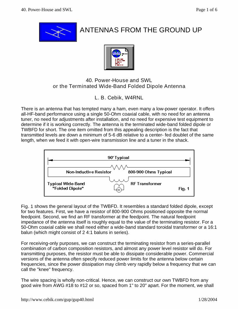
Fig. 1 shows the general layout of the TWBFD. It resembles a standard folded dipole, except for two features. First, we have a resistor of 800-900 Ohms positioned opposite the normal feedpoint. Second, we find an RF transformer at the feedpoint. The natural feedpoint impedance of the antenna itself is roughly equal to the value of the terminating resistor. For a 50-Ohm coaxial cable we shall need either a wide-band standard toroidal transformer or a 16:1 balun (which might consist of 2 4:1 baluns in series).
For receiving-only purposes, we can construct the terminating resistor from a series-parallel combination of carbon composition resistors, and almost any power level resistor will do. For transmitting purposes, the resistor must be able to dissipate considerable power. Commercial versions of the antenna often specify reduced power limits for the antenna below certain frequencies, since the power dissipation may climb very rapidly below a frequency that we can call the "knee" frequency.
The wire spacing is wholly non-critical. Hence, we can construct our own TWBFD from any good wire from AWG #18 to #12 or so, spaced from 1" to 20" apart. For the moment, we shall
Page 1 of 640. Power-House and SWL
1/28/2004http://www.cebik.com/gup/gup40.html

not specify the antenna length, although the wire length will be important to one aspect of antenna operation. However, one commonly used length is about 90' or 27 meters. This length is about 1/2-wavelength between 5 and 6 MHz.
Fig. 2 gives us some vital information on the anticipated performance of the 27.2-m (90') TWBFD. The bottom line shows the modeled gain of the antenna in question. The top line shows the modeled gain of a plain, single wire doublet that is the same length as the TWBFD. If we ignore the portion of the lower curve that descends rapidly, the doublet shows at least 5 dB more gain everywhere across the operating spectrum.
However, the TWBFD does have that region of rapidly decreasing gain. In that region, the SWR on the coaxial feedline smooths out, compared to the ripples in the curve above the 5-6-Mhz knee frequency. The reason is very straightforward: below the knee frequency, more and more of the power fed to the antenna dissipates in the terminating resistor. That power is not available for radiation. However, the smooth near-50-Ohm impedance that produces the low SWR can give us the impression of good antenna operation. Actually, the antenna performs better at higher frequencies, where the SWR shows considerable variation between 1.0:1 and 2.0:1.
Page 2 of 640. Power-House and SWL
1/28/2004http://www.cebik.com/gup/gup40.html

Because the terminating resistor determines the antenna's characteristic feedpoint impedance, the resistor must be non-inductive, that is, not wire-wound. It should be capable of dissipating half or more of the power fed to the antenna. Since 800-900-Ohm non-inductive resistors are difficult to find, some builders use a 16:1 balun at the resistor point and install a 50-Ohm resistor. Other schemes are also possible.
The reason why many builders favor an 800-Ohm terminating resistor is that the higher the value of the terminating resistor, the smoother the SWR curve above the knee frequency. For a receive-only antenna, where SWR may be less critical, values from 200 to 400 Ohms have been used successfully. Higher values are rarely used because of the difficulty of transforming the high feedpoint impedance to 50 Ohm coaxial cable.
One poorly understood feature of the TWBFD is that its patterns are exactly the same shape as those produced by a single-wire doublet of the same length. Fig. 3 provides a random sample at 10 Mhz, comparing the patterns of the TWBFD and a doublet. As the figure makes plain, the doublet pattern is about 6 dB stronger. Depending upon the calibration of the S-meter in your rig, the difference is at least 1 S-unit. For those running very low power, where signals may be at the threshold of readability under the best of conditions, losing an S-unit from the transmitted signal may mean the difference between a contact and no contact.
Reception, however, is rarely a major problem, since most receivers have excess gain. Seldom do we move the volume control more than 20 to 30 degrees above the lowest level.
Page 3 of 640. Power-House and SWL
1/28/2004http://www.cebik.com/gup/gup40.html
Many transceivers also have receiving pre-amps to increase signal strength by 10 to 20 dB. Hence, the 6 dB loss of the TWBFD is not a significant receiving problem. In some cases, such as reception in the night-time 40-meter band, the inherent loss can reduce receiver front-end overload from short-wave broadcasting stations.
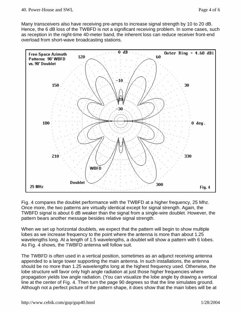
Fig. 4 compares the doublet performance with the TWBFD at a higher frequency, 25 Mhz. Once more, the two patterns are virtually identical except for signal strength. Again, the TWBFD signal is about 6 dB weaker than the signal from a single-wire doublet. However, the pattern bears another message besides relative signal strength.
When we set up horizontal doublets, we expect that the pattern will begin to show multiple lobes as we increase frequency to the point where the antenna is more than about 1.25 wavelengths long. At a length of 1.5 wavelengths, a doublet will show a pattern with 6 lobes. As Fig. 4 shows, the TWBFD antenna will follow suit.
The TWBFD is often used in a vertical position, sometimes as an adjunct receiving antenna appended to a large tower supporting the main antenna. In such installations, the antenna should be no more than 1.25 wavelengths long at the highest frequency used. Otherwise, the lobe structure will favor only high angle radiation at just those higher frequencies where propagation yields low angle radiation. (You can visualize the lobe angle by drawing a vertical line at the center of Fig. 4. Then turn the page 90 degrees so that the line simulates ground. Although not a perfect picture of the pattern shape, it does show that the main lobes will be at
Page 4 of 640. Power-House and SWL
1/28/2004http://www.cebik.com/gup/gup40.html
high elevation angles.) For very broad frequency coverage, some installations use two TWBFD antennas--a long one for the lower portion of the HF spectrum, and a shorter one for the upper regions.
Thus, we have two frequencies of concern for any TWBFD: the frequency at which the antenna is more than 1.25 wavelengths long (if installed vertically) and the knee frequency.
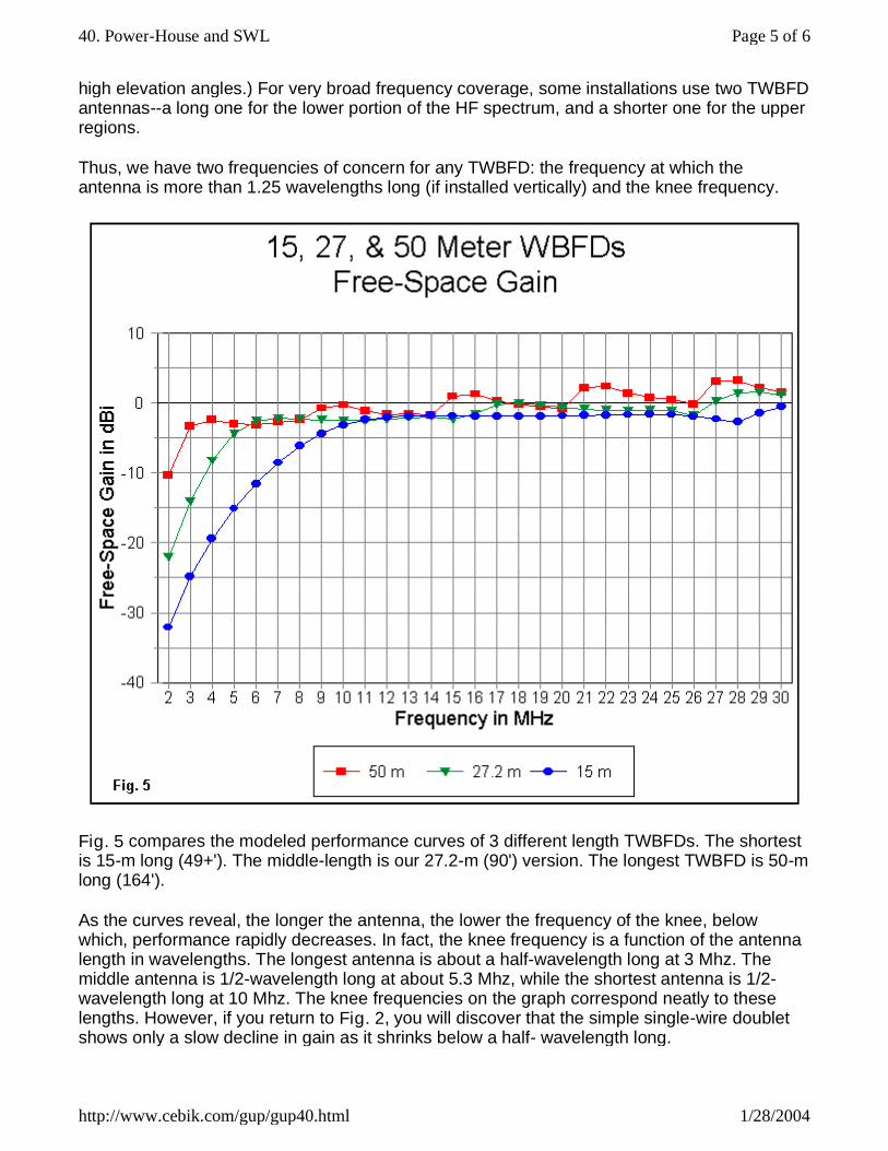
Fig. 5 compares the modeled performance curves of 3 different length TWBFDs. The shortest is 15-m long (49+'). The middle-length is our 27.2-m (90') version. The longest TWBFD is 50-m long (164').
As the curves reveal, the longer the antenna, the lower the frequency of the knee, below which, performance rapidly decreases. In fact, the knee frequency is a function of the antenna length in wavelengths. The longest antenna is about a half-wavelength long at 3 Mhz. The middle antenna is 1/2-wavelength long at about 5.3 Mhz, while the shortest antenna is 1/2-wavelength long at 10 Mhz. The knee frequencies on the graph correspond neatly to these lengths. However, if you return to Fig. 2, you will discover that the simple single-wire doublet shows only a slow decline in gain as it shrinks below a half- wavelength long.
Page 5 of 640. Power-House and SWL
1/28/2004http://www.cebik.com/gup/gup40.html

The TWBFD and many other variants on the terminated doublet theme are most favored by two groups of people. First are European short-wave listeners. The decreasing performance of the antenna at lower frequencies is actually a blessing where short-wave broadcasts routinely overload receivers so that a station appears everywhere on the dial. The second group of users tend to be military and government installations where transmitted power is no problem. What they need is quick installation and no-adjustment operation.
Whether the antenna is suitable for radio amateur use is a user judgment. There are trade-offs to be measured, and only the user can measure them.
Updated 11-06-2003. © L. B. Cebik, W4RNL. Data may be used for personal purposes, but may not be reproduced for publication in print or any other medium without permission of the author.
Go to series index page
Return to Amateur Radio Page
Page 6 of 640. Power-House and SWL
1/28/2004http://www.cebik.com/gup/gup40.html