an investigation of magnetic antennas for ground penetrating radar pt
TRANSCRIPT

Progress In Electromagnetics Research, PIER 43, 257–271, 2003
AN INVESTIGATION OF MAGNETIC ANTENNAS FORGROUND PENETRATING RADAR
P. T. Bellett and C. J. Leat
Cooperative Research Centre for Sensor Signaland Information Processing (CSSIP)University of QueenslandSt Lucia, Brisbane, QLD 4072, Australia
Abstract—For ground penetrating radar (GPR), smaller antennaswould provide considerable practical advantages. Some of which are:portability; ease of use; and higher spatial sampling. A theoreticalcomparison of the fundamental limits of a small electric field antennaand a small magnetic field antenna shows that the minimum Qconstraints are identical. Furthermore, it is shown that only the smallmagnetic loop antenna can be constructed to approach, arbitrarilyclosely, the fundamental minimum Q limit. This is achieved withthe addition of a high permeability material which reduces energystored in the magnetic fields. This is of special interest to some GPRapplications. For example, applications requiring synthetic aperturedata collection would benefit from the increased spatial samplingoffered by electrically smaller antennas. Low frequency applicationsmay also benefit, in terms of reduced antenna dimensions, by the useof electrically small antennas. Under these circumstances, a magnetictype antenna should be considered in preference to the typical electricfield antenna. Numerical modeling data supports this assertion.
1 Introduction
2 A Measure for Antenna Bandwidth
3 Fundamental Limits of Small Antennas Apply Equallyto Magnetic and Electric Dipoles
4 Magnetic Antenna Alone Able to Approach Chu Limit
5 Method
6 Discussion

258 Bellett and Leat
7 Conclusions
Acknowledgment
References
1. INTRODUCTION
Given the dominance in GPR antenna design of the requirement forwide bandwidth, it may seem a peculiar choice to consider the loopantenna. This is especially true considering the fact that the penaltyincurred in the radiation resistance of an electrically small magneticloop antenna is more severe than the small electric dipole antenna.The obvious objection is that the fractional bandwidth,
Bfrac ≈1Q
=RradX
, (1)
is much smaller for a typical single turn loop antenna than a typicalsmall electric dipole of length equal to the loop’s diameter. The reasonfor this may be understood by considering the destructive effect uponradiation of the oppositely directed currents on either side of theloop. However, it has been established by Chu [1] that this apparentlimitation is not fundamental to magnetic dipole antennas. Indeed,magnetic dipole antennas may be constructed which approach thetheoretical best performance more closely than electric dipoles [2].These matters are considered more closely in Section 4.
The idea of using magnetic loop antennas for GPR is not new.However, very little published record is available in the literature.From the small number of available publications, the loop is typicallyused only as a receive probe. Yarovoy et al. [3] claims an advantagein making a more compact GPR antenna by using a loop as areceive antenna to obtain a higher spatial sampling by receiving thefields at a local point. Compared with a linear dipole of similaraperture, their loop antenna is reported to have a very small amount ofringing. Yarovoy et al. use the loop below a dielectrically loaded hornantenna with a cross-polarized orientation so the loop is insensitiveto the transmitted fields. Chubinsky [4] and de Jongh [5] reportthe use of a loop probe to assess the performance of GPR antennas.The magnetic loop probe is placed underneath the ground and usedto measure the radiation pattern in the lower half-space. Also ofspecial interest, in the context of GPR, is the array of shielded loopantennas used by Sato et al. [6] for a directional borehole radar receiveantenna. Each of the loop antennas are fed against a thick conducting

An investigation of magnetic antennas for GPR 259
cylindrical sleeve surrounding the borehole radar probe. The currentsinduced on the cylindrical conducting surface of the borehole probe byincoming electromagnetic waves are measured by the small broadbandloop probes. In a later publication [7], two different current probeorientations were used to separately measure two components of themagnetic field on the conducting cylinder (i.e., Hz and Hφ).
Further support for the use of loop antennas in GPR comesindirectly from complementary antenna structures, such as thecomplementary bowtie [8] and the slot antenna. As an example, amagnetic dipole slot antenna is used by Sato [9] to provide a cross-polarized receive antenna for borehole radar. A slot antenna is alsoconsidered by Druchinin [10] for GPR that has an optimized “front toback” radiation pattern ratio by the use of a resistive material. Boththese antenna types can be conceptualized as two adjacent currentloops.
In addition, we believe that some benefits may be offered due tothe predominantly magnetic near fields of the magnetic antenna beinginsensitive to changes in permittivity. Such changes may frequentlyhappen in ground-contact GPR as the antenna feed-point traversesground of varying nature [11] and at varying effective heights.
The structure of this paper will be to expand the argumentfor GPR loop antennas, drawing upon the literature and analyticalmethods, and then to examine critically the conclusions using theresults from a number of numerical models. Firstly, readers arereminded of the use of quality factor and its relationship to smallantenna bandwidth.
2. A MEASURE FOR ANTENNA BANDWIDTH
The quality factor (Q) is a dimensionless quantity used as a measureof the bandwidth or frequency selectivity of a resonant circuit and isdefined as [12],
Q = 2πTime-Avg. Energy Stored at a resonant frequencyEnergy dissipated in one period of this frequency
. (2)
It can readily be shown that the relative bandwidth is inversely relatedto Q. The Q-factor is a general concept and is not restricted toresonant electrical circuits. However, for an electric circuit withcomplex impedance Z = R + iX = |Z|eiδ tuned to resonance withan equal amount of opposite reactance (i.e., −X), the Q of the circuitmay be approximated as,
Q ≈ X
R= tan δ. (3)

260 Bellett and Leat
Where X is the reactive component and R is the resistive component ofthe complex impedance Z. This is a reasonable approximation whereone type of energy storage is predominant, such as magnetic energy inthe case of the small loop antenna.
3. FUNDAMENTAL LIMITS OF SMALL ANTENNASAPPLY EQUALLY TO MAGNETIC AND ELECTRICDIPOLES
The problem of an arbitrary antenna geometry supporting an arbitrarybut axi-symmetric current distribution is addressed in an elegantmathematical formulation by Chu [1]. Chu’s approach concealedall the physical details of the antenna inside the smallest possibleenclosing sphere and considered only the fields outside the sphere.In showing the physical limitations of omni-directional antennas,Chu represents the fields outside the sphere as a complete set oforthogonal, spherical waves, propagating radically outward. For avertically polarized electric dipole, omni-directional antenna, onlyTMm0 circularly symmetric, Hankel-Legendre modes are required. Foreach of the modes, the apparent impedance implied by the ratio of theelectric (Eθ) and magnetic (Hφ) fields is constant over the surface ofthe sphere [13]. Thus:
Z =EθHφ
= |Z|eiδ (4)
To a good approximation, the Q for each spherical wave mode maybe evaluated in accordance with the resonant circuit analogy ofEquation (3), the ratio of stored verses radiated energy. Because ofthe orthogonal nature of the spherical wave modes, the Q is formedfrom the independent contribution of all the modes.
To deal with the fact that the fields outside the antenna spheredo not uniquely define a current distribution, Chu assumes that anoptimal antenna exists with an appropriate source distribution insidethe sphere. The antenna (or its matching circuit) provides adequateenergy storage inside itself to tune the reactive energy storage of thespace outside the antenna sphere. It is also assumed that the only lossmechanism is associated with the radiation resistance of the antenna;implying a radiation efficiency of 100%.
The fields of the magnetic dipole correspond to Chu’s TE modes,for which the energy storage and radiation and, hence, Q contributions,are the same as the TM modes of the electric dipole. Thus, for thepurposes of this paper, the interesting result of Chu’s work is therealization, which is entirely sensible in terms of complementarity,

An investigation of magnetic antennas for GPR 261
that the minimum Q of a magnetic antenna, corresponding to his TEmodes, is the same as that of an equivalently sized electric antenna,corresponding to his TM modes.
4. MAGNETIC ANTENNA ALONE ABLE TOAPPROACH CHU LIMIT
In Section 3, it was indicated from Chu’s analysis, based on thefields external to the containing volume, that the minimum possibleQ for magnetic and electric dipoles is the same. This needs to bereconciled with the earlier statement regarding the generally high Q ofloop antennas resulting from a low radiation resistance. Now considerthe argument that a magnetic antenna filling the Chu sphere may beconstructed to add no extra energy storage inside the sphere usingavailable materials, but that the equivalent cannot be said for theelectric antenna.
The fundamental limitation on bandwidth and performance ofsmall antennas was first introduced by Wheeler [14] in 1947 in terms ofa “radiation power factor,” described as proportional to the “effectivevolume” of a small antenna. Wheeler describes a small antenna asequivalent to either a capacitor or an inductor, consequently requiringan additional reactor of the opposite kind to tune to a resonance. Thisis in line with the lumped circuit model, inspired by the theoreticalargument of dominant fields, from the analytic expressions for anelectric and magnetic dipole. The “power factor” Wheeler speaksof is now more preferably referred to in terms of the radiation Q ofan antenna. The “power factor” can be interpreted as the fractionalbandwidth (Bfrac = ∆f/f0) or the inverse of the antenna Q.
Before continuing, it is important to re-examine the importantdifference between the two types of small radiators. The radiationfrom an electric dipole is a direct consequence of the completion ofthe current path along the antenna conductor in the capacitance ofthe space surrounding the antenna. Maxwell explains this with theaddition of a displacement current density term to Ampere’s Law.This is distinct from the magnetic dipole that radiates because ofthe completion of a magnetic flux path in the space surrounding theantenna. The continuous magnetic flux paths that must necessarilyexist around the current path of the equivalent small conducting loopantenna helps to visualize this. By thinking of the electric dipole as aparallel plate capacitor and the magnetic dipole as an inductor, it iseasier to visualize that the flux tubes inside and outside the capacitorare in the same direction; thus, in effect, in parallel. However, theyare antiparallel and thus, in series, for the inductor. Wheeler [2]

262 Bellett and Leat
states that, “decreasing the effective length of the internal flux path byinserting some material has the effect of increasing the stored energy inthe capacitor but decreasing it in the inductor.” This can be explainedin terms of the boundary conditions imposed by Maxwell’s equations.In the case of the capacitor, the tangential component of the electricfield must be the same on either side of the boundary. If a higherpermittivity (εr > 1) material is placed inside the capacitor, the energydensity inside will increase according to Equation (6). The energystored in the magnetic field of an inductor and the electric field of acapacitor are given by Cheng [12] as,
W̃m =∫∫ν
∫ 12µ|H|2dν = Time-Average Magnetic Energy (J) (5)
and
W̃e =∫∫ν
∫ 12ε|E|2dν = Time-Average Electric Energy (J) (6)
For the magnetic loop, or the inductor, the normal component of themagnetic flux density must be equal across the boundary; imposed bythe solenoid nature of B (i.e., ∇ · B = 0) . Consequently, Equation(5) needs to be re-written in terms of the magnetic flux density (B)instead of the magnetic intensity vector (H),
w̃m =|B|22µ
(J/m3). (7)
Tangential H is not continuous within and without the inductor, dueto the surface currents imposed by the exciting loop. Equation (7)now reveals that the insertion of a material with higher permeability(µr > 1) inside the inductor reduces the energy density within.Conversely, the effective radioactive strength of the magnetic dipoleis dependent on the B flux emerging from the poles, which has alreadybeen shown to be unaffected due to the solenoid principle. Such areduction in stored energy inside the radian sphere has the effectof reducing the Q of the small loop antenna. No readily availablematerials have an equivalent effect for the small electric field antenna.This would require a relative dielectric constant less than unity.
Wheeler [15] described a small spherical inductor which is“conceptually filled with a perfect magnetic material, so there is nostored energy inside the sphere.” This provides the optimal (minimumQ) lossless antenna within a spherical volume of radius a, since anyreactive fields at r < a can only add to the amount of stored energy

An investigation of magnetic antennas for GPR 263
and increase the Q. It is assumed that no loss mechanism exists inthe permeable material or the conducting wire, with the only lossattributed to the radiation resistance. In other words, how close thebandwidth of an electrically small antenna gets to the fundamentallimit is determined by how effective the antenna geometry is in makinguse of the volume within the antenna sphere to avoid energy storage.Energy storage outside the antenna sphere is completely unavoidable.The minimum Q is formulated by Wheeler [2] in terms of effectivevolume as,
Q ≈ 1(ka)3
=Volume of Radiansphere
Volume of Antenna Sphere, (8)
where k is the wave number and a is the antenna sphere radius. Theeffect of an imperfect magnetic (i.e., µr �=∞) material is predicted byWheeler by an additional term to Equation (8),
Q =1
(ka)3
[1 +
1µr
]. (9)
Equation (9) predicts that, provided a material can be manufacturedwith a large enough µr, the effect of using a finite permeability materialproduces only a marginal increase in the minimum obtainable Q. Forexample, µr = 50 gives only a 2% increase in Q, which is a tolerablecompromise.
We arrive at an important result; the loop antenna is capableof achieving the theoretical limit of maximum bandwidth for a smallantenna, while an electric antenna apparently cannot. There havebeen numerous attempts to approach the ideal for electric dipoles. Asis clear from above, dielectric material is counterproductive in thisaim. Practical approaches use conducting material to eliminate energystorage from parts of the antenna sphere, and provide large capacitivehats to avoid electric field concentrations. An example of a smallantenna designed to reduce energy storage within the antenna sphereis Goubau’s [16] multi-element monopole antenna.
In the remainder of the paper we use numerical models to verifythese assertions by comparing the Q of equivalently sized dielectricallyloaded electric dipoles antennas with permeability loaded magneticdipoles antennas.
5. METHOD
Agilent’s High Frequency Structure Simulator (HFSS) [17] was usedto produce finite element models of equivalently sized electric dipole

264 Bellett and Leat
Figure 1. The experimental magnetic loop antenna used for theQ measurements above a “real ground” half-space. The low ESRcapacitor used to tune the loop is shown in the foreground at thefeed-point of the loop antenna.
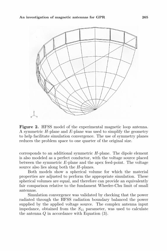
antennas and magnetic loop antennas. The dimensions of the modeledloop antenna are taken from the experimental loop antenna shown inFigure 1. The copper structure is modeled as a perfect conductor witha height of 70 mm and an outer radius of 146 mm. The thickness ofthe loop conductor is 2 mm. The copper losses are very small andestimated to be an order of magnitude smaller then the radiationresistance of loop in free-space. The antenna feed-point is the taperedsection shown in Figure 1. The HFSS model is shown in Figure 2. Tosimplify and reduce the problem space required for meshing and to helpfacilitate simulation convergence, the HFSS model incorporates the useof symmetry planes. Geometric planes of symmetry correspondingto the electromagnetic E and H-planes of symmetry are shown inFigure 2. The symmetric E-plane is defined by the centre of the feed-point and the loop axis. The loop is fed with a voltage source that isnow placed between the E-plane and one side of the loop feed-point.It also lies along the H-plane that bisects the antenna in the plane ofthe loop. The results presented in this paper were obtained at 50 MHz,ensuring the electrically small criterion (D/λ ≈ 1/20).
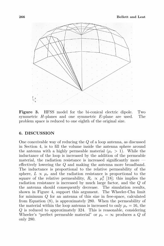
The HFSS model for the equivalently sized bi-conical electricdipole, also exploiting symmetry planes is shown in Figure 3.The electric dipole exhibits an additional geometric symmetry that
An investigation of magnetic antennas for GPR 265
Figure 2. HFSS model of the experimental magnetic loop antenna.A symmetric H-plane and E-plane was used to simplify the geometryto help facilitate simulation convergence. The use of symmetry planesreduces the problem space to one quarter of the original size.
corresponds to an additional symmetric H-plane. The dipole elementis also modeled as a perfect conductor, with the voltage source placedbetween the symmetric E-plane and the apex feed-point. The voltagesource also lies along both the H-planes.
Both models show a spherical volume for which the materialproperties are adjusted to perform the appropriate simulation. Thesespherical volumes are equal, and therefore can provide an equivalentlyfair comparison relative to the fundament Wheeler-Chu limit of smallantennas.
Simulation convergence was validated by checking that the powerradiated through the HFSS radiation boundary balanced the powersupplied by the applied voltage source. The complex antenna inputimpedance, obtained from the S11 parameter, was used to calculatethe antenna Q in accordance with Equation (3).
266 Bellett and Leat
Figure 3. HFSS model for the bi-conical electric dipole. Twosymmetric H-planes and one symmetric E-plane are used. Theproblem space is reduced to one eighth of the original size.
6. DISCUSSION
One conceivable way of reducing the Q of a loop antenna, as discussedin Section 4, is to fill the volume inside the antenna sphere aroundthe antenna with a highly permeable material (µr > 1). While theinductance of the loop is increased by the addition of the permeablematerial, the radiation resistance is increased significantly more —effectively lowering the Q and making the antenna more broadband.The inductance is proportional to the relative permeability of thesphere, L ∝ µr and the radiation resistance is proportional to thesquare of the relative permeability, Rr ∝ µ2
r [18]; this implies theradiation resistance is increased by much large factor, and the Q ofthe antenna should consequently decrease. The simulation results,shown in Figure 4, support this argument. The Wheeler-Chu limitfor minimum Q for an antenna of this size in free-space, calculatedfrom Equation (8), is approximately 280. When the permeability ofthe material within the loop antenna is increased to only µr = 16, theQ is reduced to approximately 324. This is reasonable, consideringWheeler’s “perfect permeable material” or µr = ∞ produces a Q ofonly 280.

An investigation of magnetic antennas for GPR 267
Figure 4. A modeled (HFSS) comparison of the effect of materialloading on the free-space Q of a small magnetic and electric fieldantenna. An improvement in the Q of the small magnetic loop antennais shown as a function of the relative permeability (µr > 1) of thematerial in the antenna sphere. A similar reduction is not observablewith the equivalently sized electric dipole surrounded by a higherpermittivity (εr > 1) material.
It should also be noted that the modeled materials used to loadthe antennas in this paper have lossless properties (i.e., magnetic andelectric loss-tangents are both zero) and, as a consequence, are notdirectly coupling additional dissipative losses to unfairly improve theantenna Q.
The simulated Q results shown in Figure 4 also provide supportingevidence that a small electric dipole antenna surrounded by a sphericalvolume of dielectric material with permittivity greater than air (εr >1), adversely affects the antenna bandwidth. The addition of thedielectric in the antenna sphere does reduce the capacitive reactanceof the antenna impedance, but, unfortunately, decreases the radiationresistance by a larger amount.
These loaded electric dipole results are in general supported by

268 Bellett and Leat
a recent paper by Ida [19]. However, for the cylindrical dielectricgeometry chosen by Ida, a local minima in Q is reported to exist forεr ≈ 4. These results may be particular to the geometry employed, andwere obtained for a monopole over a ground plane with an electricalsize approximately twice that of the electric dipole reported in thispaper. Also, the dielectric volume was cylindrical rather than circular.
Notably the most practical approach for improving the Q of asmall electric dipole, as discussed in Section 4, is to increase the amountof conducting material used to construct the elements of the dipole.For example, instead of uniformly sized thin wire, a bi-conical shapeddipole can be used. This is a useful argument for explaining why thefractional bandwidth of the small electric antenna is generally thoughtof as being much larger than an equivalently sized small magneticantenna. This is consistent with the general use of bi-conical orpyramidal shaped electric dipoles in GPR. It is also generally acceptedthat such shapes offer greater frequency independence. However, adistinction should be made in the case of the electrically small antenna.These shapes are partially frequency independent in the sense of beingmainly defined by angle, but the improved bandwidth in the case ofelectrically small antennas is a result of the larger surface over whichcharges can be spread to reduce the electric field strength.
The bi-conical electric dipole used in these simulations (Figure 3)has an inclusive angle of 60 degrees. With this increase in the amountof conductive material within the antenna sphere, the Q is seen inFigure 4 to be almost a factor of 1.5 better than the equivalent sizedloop antenna (Figure 2). Additional simulation results of the bi-conical antenna with inclusive angles of 10 and 30 degrees support theconcept of energy storage reduction within the antenna sphere withthe use of highly conducting materials. The capacitive reactance ofthe dipole is seen to increase with a decrease in the inclusive angle,while not significantly affecting the radiation resistance. This resultsin an improved or lower Q in accordance with Equation (3), as theinclusive angle is increased.
Reducing the inner radius of the loop annulus achieves a similarreduction in the amount of reactive stored energy by increasingthe amount of conducting material within the loop antenna sphere.However, unlike the electric dipole, the increase in conductingmaterial also has a deleterious effect on the loop radiation resistance,consequently counteracting any gain in bandwidth. This is because ofthe very strong relationship between the loop radius and the radiationresistance (Rrad ∝ r4) [18], and the fact that the inner loop radius hasbeen reduced.
These results show that if antennas are required to be electrically

An investigation of magnetic antennas for GPR 269
small, magnetic loop antennas can be constructed to closely achievethe fundamental bandwidth limit of small antennas. It should alsobe recognized that while the achieved Q is still high is terms ofthe bandwidth required for GPR, this value is indicative of theonly loss being attributed to radiation. It is common practice toresistively load GPR antennas to compromise radiation efficiency forbandwidth. Furthermore, these results are for antennas in free-space. The proximity to a typical ground half-space may also provideadditional benefit for small GPR antennas [13].
7. CONCLUSIONS
It has been shown that for GPR applications that require electricallysmaller antennas, they are best constructed as loop antennas. Suchmagnetic antennas may achieve the lowest theoretical ringing for agiven antenna size constraint. The bandwidth of a small magneticantenna can be improved by the inclusion of a higher permeabilitymaterial within the near-field surrounding the antenna. A similarimprovement is not easily achievable with readily available dielectricmaterials, with a higher permittivity material having an adverse effecton the bandwidth of a small electric antenna.
ACKNOWLEDGMENT
The authors would like to acknowledge Glen Stickley for commentingon the manuscript.
REFERENCES
1. Chu, L. J., “Physical limitations of omni-directional antennas,”Journal of Applied Physics, Vol. 19, 1163–1175, 1948.
2. Wheeler, H. A., “The radiansphere around a small antenna,”Proceedings of the I.R.E., Vol. 47, 1325–1331, 1959.
3. Yarovoy, A. G., P. V. Genderen, and L. P. Ligthart, “Groundpenetrating impulse radar for landmine detection,” EighthInternational Conference on Ground Penetrating Radar, GPR2000, 856–860, Gold Coast, Australia, May 23–26, 2000.
4. Chubinsky, N. and A. Krampuls, “Probe of pulse amplitude ofelectromagnetic field for investigation of GPR antenna perfor-mance,” Eighth International Conference on Ground PenetratingRadar, GPR 2000, 75–79, Gold Coast, Queensland, Australia,May 23–29, 2000.

270 Bellett and Leat
5. De Jongh, R. V., A. G. Yarovoy, I. V. Kaploun, and A. D. Schukin,“Design and analysis of new GPR antenna concepts,” SeventhInternational Conference on Ground Penetrating Radar, GPR’98,81–68, Lawrence, Kansas, USA, May 27–30, 1998.
6. Sato, M. and T. Tanimoto, “A shielded loop array antenna for adirectional borehole radar,” Fourth International Conference onGround Penetrating Radar, Geological Survey of Finland, 323–327, Rovaniemi, Finland, June 8–13, 1992.
7. Ebihara, S., M. Sato, and H. Niitsuma, “Estimation of wavepolarization in directional borehole radar measurements with themusic algorithm,” The Third Well Logging Symposium of Japan,1–8, Chiba, Japan, September 25–25, 1997.
8. Chong, A. A., “Complementary GPR antennas and watertanktesting,” M.Eng.Sc. (Research) Thesis in Department of ComputerScience and Electrical Engineering, University of Queensland,Australia, 2001.
9. Sato, M., T. Ohkubo, and H. Niitsuma, “Cross-polarizationborehole radar measurements with a slot antenna,” Journal ofApplied Geophysics, Vol. 33, 53–61, 1995.
10. Druchinin, S. V., “Analysis of characteristics of a slot antennaused in georadar,” Seventh International Conference on GroundPenetrating Radar, GPR’98, 643–648, Lawrence, Kansas, USA,May 27–30, 1998.
11. Noon, D. A. and R. M. Narayanan, “Subsurface remote sensing,”Review of Radio Science 1999–2002, W. Ross Stone (Ed.), 535–552, IEEE Press and John Wiley & Sons, 2002.
12. Cheng, D. K., Field and Wave Electromagnetics, Second Edition,Addison Wesley, 1989.
13. Leat, C. J., “The fundamental limit of small antenna bandwidth:How it affects small GPR antennas,” Workshop on Applicationsof Radio Science, WARS’02, Leura, Australia, February 2002.
14. Wheeler, H. A., “Fundamental limitations on small antennas,”Proceedings of the I.R.E., Vol. 35, 1479–1484, 1947.
15. Wheeler, H. A., “Small antennas,” IEEE Transactions onAntennas and Propagation, Vol. AP-23, No. 4, 462–469, 1975.
16. Goubau, G., “Multi-element monopole antenna,” Proc. Workshopon Electrically Small Antennas ECOM, 63–67, Ft Monmouth,N.J., May, 1976.
17. Agilent, Agilent High-Frequency Structure Simulator, Version 5.6,Agilent Technologies, 2000.
18. Balanis, C. A., Antenna Theory Analysis and Design, Second

An investigation of magnetic antennas for GPR 271
Edition, John Wiley & Sons, 1997.19. Ida, I., J. Sato, T. Sekizawa, H. Yoshimura, and K. Ito,
“Dependence of the efficiency-bandwidth product on electricalvolume of small dielectric loaded antennas,” IEEE Transactionson Antennas and Propagation, Vol. 50, No. 6, 821–826, 2002.