antenna systems for broadband wireless access
TRANSCRIPT

Submitted to IEEE Communications Magazine
Special Issue on Wideband Wireless Access Technologies to Broadband Internet
Antenna Systems for Broadband Wireless Access
Ross D Murch# and K. B. Letaief
Center for Wireless Information Technology Department of Electrical and Electronic Engineering
Hong Kong University of Science and Technology Clear Water Bay, Kowloon, Hong Kong
[email protected] and [email protected]
Abstract
Broadband wireless access along with evolving mobile Internet and multimedia services are driving the recent surge of research and development activities for future wireless communication systems. In this paper, we provide an overview of antenna systems for broadband wireless communications and introduce some of the important issues surrounding them. The approach we use is to first provide a general framework of how antenna systems may be utilized in wireless communication systems and then describe the antenna systems themselves. In particular, we consider antenna systems for the base station, mobile station and then finally multiple input and multiple output antenna systems where antenna systems are utilized at both the base and mobile stations.
# Corresponding Author. Tel: +852 2358 7044. Fax: +852 2358 1485.
This is the Pre-Published Version

2
In recent years, there has been a substantial increase in the development of
broadband wireless access technologies for evolving wireless, mobile Internet services
and next-generation cellular systems. These technologies must be able to cope with the
challenging wireless environment and antenna systems in the form of adaptive arrays or
smart antennas can provide an effective and promising solution while achieving
reliable and robust high speed and high data rate transmission. Such systems have
been proposed for wireless communications for many years [1-2]. Recently, however,
research and development in this area has significantly increased [3-4] and many
commercial products are now readily available for wireless communication systems.
In addition, recently proposed multiple input multiple output (MIMO) antenna
systems [4] or space division multiplexing (SDM) systems are further revolutionizing
antenna systems for wireless communications.
The reason for the renaissance of antenna systems is that they have become one of
the key technologies for increasing capacity and data rates of wireless communication
systems. Their use helps mitigate three major impairments caused by the wireless
channel; namely, fading, delay spread and co-channel interference. The earliest form
of antenna systems for improving the performance of wireless communication
systems was in the form of antenna diversity and it helps mitigate the effects of
fading. Antenna diversity has been in commercial use at the base station of most
wireless communications for many years. Over the last two decades, smart antenna
systems (or adaptive antennas), which attempt to actively mitigate co-channel
interference, have also been developed [1-2] and commercial systems are now
appearing at the base station. Recently, there have also been some important
developments and these include the idea of space-time receivers, space-time coding,
and SDM antenna systems. The proposed wireless metropolitan area network

3
(Wireless MAN) standard IEEE 802.16, which is aimed at wireless broadband access
is also considering the use of antenna systems for performance improvement.
In this paper, we attempt to provide an overview of all of these antenna systems
for wireless broadband communications and introduce some of the important issues
surrounding them. Our basic definition of an antenna system is any adaptive
configuration of multiple antennas that improves the performance of the wireless
communication system. The key points are that the system must be adaptive and
consist of multiple antennas. Our definition includes diversity, smart or adaptive
antenna systems, and MIMO or SDM antenna systems. It is also important to note that
the particular form of the antenna system depends on the exact wireless system
configuration, whether it is used for reception or transmission, and if it is at the base
station or mobile station.
The organization of this paper is as follows. In Section 1, we introduce a
framework and some general concepts that form the basis for most antenna systems.
In Section 2, we discuss antenna systems in which there are multiple antennas at the
base station and only a single antenna at the mobile station. In Section 3, we discuss
smart antenna systems at the mobile station while in Section 4 we introduce recently
developed techniques based on smart antennas at both the base and mobile stations
also known as MIMO or SDM antenna systems. Finally, in Section 5 we summarize
the paper.
1. Framework
Wireless communication systems usually perform duplex communication
between two points and here we define these two points as the base station (BS) and
the mobile station (MS). In a duplex wireless communication system, it is important
to understand that there can be up to four antenna systems operating. There can be

4
two systems in the downlink; namely, an antenna system for transmission at BS and
another antenna system for reception at MS. Additionally, there can be two systems
for the uplink, namely transmission at MS and reception at BS. An example of such a
system is illustrated in Figure 1 where the 4 antenna systems can be readily seen. It
should be noted that at the MS in Figure 1, the antennas for transmission and
reception are shared, thus, providing some simplification. In general, there are M
antennas at the BS for transmission, N antennas for reception at MS, K antennas for
transmission at the MS and L antennas for reception at the BS. Since the antennas at
the MS are shared the number of antennas needed at the MS is the maximum of either
N or K. At the BS and MS, the transmission and reception processing are performed
separately as indicated by the separate blocks in Figure 1.
Figure 1: General Antenna System for Wireless Broadband Communications
In a conventional GSM system, for instance, diversity combining using 2
antennas is performed on the uplink only and therefore using our terminology it is
characterized with M=1, L=2 and N=K=1. Typically, when M and N are both greater
Wireless Channel
N
K
Mobile station
Transmit Process
Receive Data
Transmit Data
Receive Process
Receive Data
M
L
Transmit Process
Basestation
Transmit Data
Receive Process

5
than 1 we refer to the system as a MIMO system in the downlink (or when K and L
are both greater than 1 as a MIMO system in the uplink) and this has been popularized
by the V-BLAST architecture [4].
An intuitive picture of the operation of the antenna systems can be obtained with
reference to Figure 2 where the antenna patterns for 2 configurations are illustrated. In
Figure 2a, we illustrate an uplink system where K=1 and L>1 and observe that the MS
radiates omni-directionally while the BS is able to shape its antenna pattern and focus
it onto the MS while also rejecting interference through pattern nulls. This process is
often referred to as spatial filtering since signals arriving in different spatial directions
are treated differently. It should be noted that such a picture of the smart antenna is
highly simplified.
Figure 2: Uplink Antenna Systems a) BS Antenna system with K=1 and L>1. b)
MIMO antenna system with K>1 and L>1.
Nulls for rejecting undesired signal streams
MS BS
Nulls for interference rejection
MS
BS a)
b)
6
In practice, it is likely that the desired and interfering signals will arrive from
many different directions and therefore the actual beam pattern on the right-hand-side
of Figure 2a may appear completely different and will not reflect a focusing process.
In Figure 2b, we also illustrate a MIMO system where both K>1 and L>1 and several
data streams are sent simultaneously over the wireless channel. In this example, each
antenna at the MS transmits a different data stream and radiates them omni-
directionally. At the BS, the antenna is able to form several beams that can select each
of the data streams and correctly receive them. In this example, it is clear that the
capacity of the system has been increased by a factor of three compared to a
conventional system and this is one reason why MIMO systems are generating so
much excitement [4].
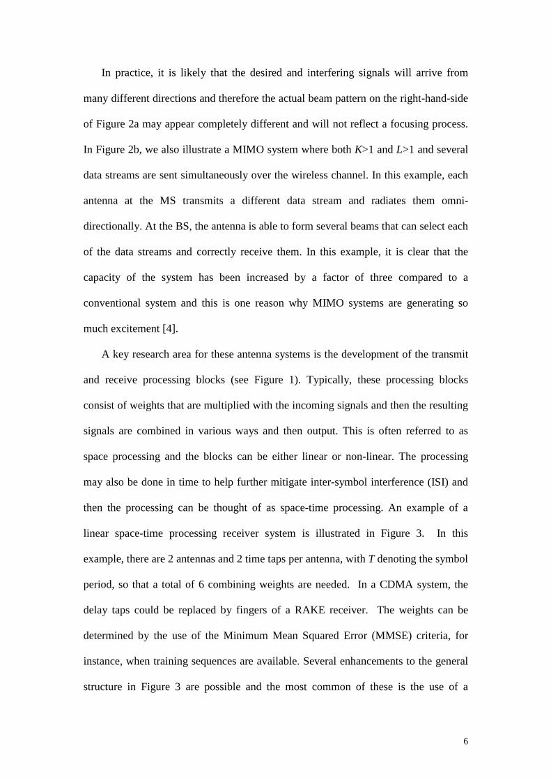
A key research area for these antenna systems is the development of the transmit
and receive processing blocks (see Figure 1). Typically, these processing blocks
consist of weights that are multiplied with the incoming signals and then the resulting
signals are combined in various ways and then output. This is often referred to as
space processing and the blocks can be either linear or non-linear. The processing
may also be done in time to help further mitigate inter-symbol interference (ISI) and
then the processing can be thought of as space-time processing. An example of a
linear space-time processing receiver system is illustrated in Figure 3. In this
example, there are 2 antennas and 2 time taps per antenna, with T denoting the symbol
period, so that a total of 6 combining weights are needed. In a CDMA system, the
delay taps could be replaced by fingers of a RAKE receiver. The weights can be
determined by the use of the Minimum Mean Squared Error (MMSE) criteria, for
instance, when training sequences are available. Several enhancements to the general
structure in Figure 3 are possible and the most common of these is the use of a
7
decision feedback in both time and space. A thorough investigation into the
performance of various space-time configurations is provided in [5].
Another aspect that needs to be considered is the kind of channel state
information (CSI) that is available. It is generally assumed that CSI is available at the
receiver of most antenna systems. However, CSI is not automatically available at the
transmitter and depending on the particular technique CSI will or will not be needed.
Therefore, the transmitter processing blocks in Figure 1 will have to rely on either no
CSI or at best some approximation of it. As a result, we can expect some performance
reduction at the transmitter side of the antenna processing blocks.
Figure 3: An example of a space-time receiver with 2 antennas and 2 time taps.
The type of wireless system used is also important. For example, CDMA systems
typically have time diversity already incorporated through the use of the RAKE
receiver and the antenna system is mainly needed for controlling CCI or MAI.
However, in a TDMA system, the antenna system ideally should provide both
diversity and mitigate CCI.
T T
w21 w23 w22
T T
w11 w13 w12
∑

8
In the remainder of this paper, we discuss the various antenna system
configurations. Specifically, in Section 2 we look at BS antenna systems where M>1
for downlink systems and L>1 for uplink systems while both N=K=1 (i.e., with a
single antenna used at the MS.) In Section 3, we briefly consider MS antenna systems
in which M=L=1 and N>1 for downlink operation and K>1 for uplink operation. In
Section 4, we consider MIMO systems where M and N are greater than 1 for downlink
systems and K and L are greater than 1 for uplink systems. Finally, in Section 5 we
briefly summarize our paper.
2. BS Antenna Systems
In BS antenna systems, antenna processing is performed only at the BS in either
or both the up and downlinks. Uplink BS systems have been well studied and were the
first multiple antenna systems to be considered for wireless communications. Less
work has been performed on the downlink. However, for the wireless system to have
balanced performance in the down and up links it is very important that the downlink
also be considered.
2.1 Uplink
2.1.1 Diversity Systems
Antenna Diversity has been known for many years and has been included in the
mobile telephone BS for some time. Its primary goal is to reduce fading caused by the
wireless channel. It makes use of the principle that the signals received from two or
more antennas that are uncorrelated will have independent fading. Therefore, if one
antenna is experiencing a faded signal it is likely that the other antenna will not, so at
least one good signal can be received. Typical methods for producing uncorrelated

9
antenna signals are space, polarization or pattern diversity. Space diversity in the past
has been most common and at an outdoor BS antenna separations of around 10
wavelengths are required. Polarization diversity is, however, becoming more popular
as both antennas can be housed at the same location without spatial separation.
Three common processing techniques are used for diversity and these are known
as switch diversity, equal gain, and maximum ratio combining. In switch diversity, the
idea is to select the antenna with the best signal (usually the signal strength is taken as
a measure of signal quality but other measures can be used such as BER or signal
quality). Equal gain combining seeks to improve on this by co-phasing the signals and
adding them together. Maximum ratio combining (MRC) is the optimum method in
the presence of noise and weighting (and co-phasing) the signals before combining by
their SNRs. The bit error probability for a BPSK MRC system with L receive
antennas is given by [11]
−
≅
+
+−
−= ∑
−
= LLL
iiN
PL
b
iL
i
L
e12
4)1(
211
)1(21 1
0 γµµ (1)
where )1/( γγµ += , γ is the average SNR per channel branch and where the
asymptotic approximation, on the right hand side, is valid for 1>>γ . It is also
important to note that in antenna systems the specification of SNR can be performed
in several ways. In this example, it is also possible to express it as the average receive
SNR, γγ Lb = , and is also sometimes referred to as average SNR per bit. The
performance of MRC is plotted in Figure 2 in terms of BER performance verses SNR
per channel branch. Comparing the no diversity configuration with MRC, for
instance, we can deduce that 2 antenna diversity provides nearly 10dB advantage for
BER’s of the order of 0.01. Improvement is even greater with 3 or more antennas but
the marginal gains become less.

10
0 2 4 6 8 10 12 14 16 18 2010
−6
10−5
10−4
10−3
10−2
10−1
100
Eb/N
o [dB]
Bit
Err
or R
ate
Figure 4: BER results for maximum ratio combining when the number of receive antennas, L, varies from 1-4 in terms of the average SNR per channel branch.
2.1.2 Adaptive or Smart Antenna Systems
When strong interference is also present, diversity processing alone cannot
improve the signal. To cope with interference, smart antennas or adaptive array
processing can be utilized to shape the antenna radiation pattern in such a way as to
enhance the desired signals and null the effect of the interfering signals [1-2]. In
Figure 2a, a stylized version of this is shown where it can be observed that the main
beam is focused onto the desired signals and the nulls of the pattern are placed in
areas where interference occurs (it should again be noted that in the wireless
environment the radiating rays of the desired and interfering signals can come from
many directions and therefore the illustration in Figure 2a is simplified). The adaptive
or smart antenna processing is generally known as optimum combining and is based
on the assumption that we already know part of the desired signal through the use of a
L=1
L=2
L=3
L=4

training sequence. This known signal is then compared with what is received and the
weights in Figure 3 are then adjusted to minimize the MMSE between the known and
received signals. When no interference is present optimum combining reduces to MRC.
Some results are provided in Figure 5 for BPSK where there is one interferer with an
SIR of 10dB. Comparing this to Figure 4, we can observe that at SNR’s greater than
around 10dB the BER curves without optimum combining flatten out. This is because
the interferer dominates the noise and is the main cause of errors. However, when
optimum combining is incorporated the BER curve does not flatten out. Comparing
the optimum combining result with Figure 4 we may also note that performance is not
as good as that of the case of no interference. This is because one degree of freedom is
used to cancel the interference and therefore the diversity gain is not as large.
0 2 4 6 8 10 12 1410
−6
10−5
10−4
10−3
10−2
10−1
100
Eb/N
o [dB]
Bit
Err
or R
ate
Figure 5: An example of optimum combining when one interis present
L=1
(
L=2 (Optimucombining)
L=2 MRC)
11
16 18 20
ferer with an SIR of 10dB
m

12
Practical implementation of the optimum combining approach for TDMA systems
has been performed based on the training sequence within a timeslot. In general, a
Direct Matrix Inversion (DMI) approach is thought useful where each packet is
handled separately. Improvements to the algorithm are possible and other approaches
such as LMS and RLS are also possible.
For CDMA systems, the RAKE receiver already provides time diversity and
therefore the smart antenna will provide most of the gain in the area of CCI and MAI
reduction. For this reason, it is generally suggested that multibeam antennas should be
considered for CDMA systems [3]. Multibeam antennas use fixed beams and have
less complexity with regard to weight calculation and tracking. In addition, the
TDMA environment is characterized by a few dominant interferers, but in CDMA
there are typically many interferers and there are not enough degrees-of-freedom in
the array to cancel them all. This again supports the use of multibeam antennas for
CDMA systems.
A fundamentally different approach has also been proposed based on direction of
arrival techniques. In this technique, algorithms based on MUSIC or ESPRIT are used
to determine the directions of arrival. Once these are known, they can be combined to
find the best signal. One problem often mentioned is that the algorithms may not
perform well under realistic conditions and that in real environments there are too
many DOA to properly detect [3].
2.2 Downlink
In principle, the methods used in the uplink can be carried over to the downlink.
That is, the signal directions in Figure 2a and b can simply be reversed. However, the
main problem is that there is only limited CSI available since the transmitter cannot
13
acquire knowledge about the downlink channel. Therefore, the transmitter cannot
form the desired antenna pattern and achieve the same performance as the uplink. To
overcome this problem there are typically two approaches. The first is to devise
methods that do not require any CSI, but the problem is that performance gain is
somewhat limited. The other approach is to attempt to obtain CSI of the downlink
from the uplink receiver. In a TDD system, this is possible since the channels are in
principle reciprocal (if we ignore interference) and therefore the uplink CSI should be
closely related to the downlink CSI. Typically, however, there is a time difference
between the down and uplink estimations and therefore the channel may have altered
in this time period. In an FDD system, the up and downlink channels are uncorrelated
and therefore the uplink channel cannot be used as an estimate for the downlink.
However, there are some frequency invariant properties of the channels such as
direction of arrivals and these can be used to provide limited information about CSI.
2.2.1 Diversity
Diversity can be applied at the transmitter using the methods suggested in Section
2.1 if CSI is available. However, this is not usually the situation and one interesting
diversity idea that can be used without CSI is known as space-time coding. Space-
time coding is an effective coding technique that uses transmit diversity to combat the
detrimental effects in wireless fading channels by combining signal processing at the
receiver with coding techniques appropriate to multiple transmit antennas. A
simplified version of space-time coding can be applied to the downlink in which M=2
and N=1. This type of space-time coding, which was discovered by Alamouti [6],
achieves the same diversity advantage as MRC with two receiving antennas and one
transmit antenna. In this scheme, two signals, which are denoted by s1 and s2, are

14
simultaneously transmitted from the two BS antennas (antenna 1 and 2, respectively)
at a given symbol period. During the next symbol period signal *2s is transmitted
from antenna 1, and signal *1s is transmitted from antenna 2 where * denotes the
complex conjugate operation. The received signals are then properly combined and
then detected by a Maximum Likelihood detector. This approach is very attractive as
it has a very simple decoding process while achieving second order diversity without
bandwidth expansion. However, a 3dB power disadvantage occurs because the total
transmit power is fixed and therefore each antenna must transmit 3dB less power.
Various comparisons between space-time coding and transmitter diversity, for
instance, can be found in [7].
2.2.3 Smart Antennas
If the downlink channel is perfectly known at the BS, then transmit processing
can be obtained in a similar way to uplink combining as described in Section 2.1.2
[8]. However, when only limited information is available, then some alternative
techniques must be applied to estimate the required parameters and one approach is
given in [9]. Another approach that is often suggested if the directions of arrival can
be obtained is to use a multibeam antenna, which selects the beam that best fits the
uplink directions of arrivals and this is based on the assumption that the downlink
directions of departure are similar to the uplink directions of arrival.
3. Mobile Station Antenna Systems
The methods used for BS antenna systems in Section 2 can be directly applied to
the MS. The main constraint, however, is that the MS needs to remain compact,
comparatively low cost and its battery life not to be compromised. With these

15
constraints implementing antenna systems at the MS is significantly more difficult
because only low complexity algorithms can be used with only a limited number of
antennas. One of the major hurdles is the problem of needing additional receiver
chains and this alone will greatly impact cost and battery life. Correspondingly, only
few results are available for MS antenna systems and here we provide a brief
summary of these. As far as the authors know, the only commercial system that
employs MS diversity is the Japanese PDC system. Another area that has been
actively investigated is the realizibility of compact antennas for the MS and whether a
sufficiently low correlation coefficient (envelope correlations of less than 0.5 are
considered acceptable) can be obtained. Recent results reveal that a dual antennas can
be made compact and also provide correlations of less than 0.1 [10].
3.1 Downlink Diversity and Smart Antenna Systems
In the downlink of the MS, the receiver has CSI available and therefore diversity
and optimum combining can be implemented if suitable low complexity algorithms
can be found. A number of results have been obtained for TDMA based systems with
N=2 in which the trick has been to measure the channel of one of the antennas at one
timeslot and then the other antenna with the next timeslot and then finally combine
the antenna signals appropriately in the third and desired timeslot [11]. The advantage
of this is that only one receiver chain is needed and therefore should not impact
significantly on battery life. To reduce complexity even further the possible weights
available are restricted to a small set and the algorithm has to simply select the most
appropriate of these. Results have been achieved for both diversity and optimum
combining and good performance is achieved. Obviously in the presence of strong
Doppler, the channel estimates from the earlier timeslots become inaccurate and

16
performance degrades. Limited results have also been obtained for CDMA based
systems.
4 MIMO Antenna Systems
In MIMO antenna systems, there are multiple antennas at both the BS and MS.
For a downlink MIMO system, M>1 and N>1 while in an uplink MIMO system K>1
and L>1. MIMO antenna systems promise improved performance and bandwidth
efficiency compared to the antenna systems we have considered in Sections 2 and 3
[4]. The key reason for this is that multiple data streams or signals are transmitted
over the channel simultaneously. It is therefore possible to double, triple or quadruple
(or even more) the capacity of a system and therefore achieve some significant gains
over the methods in Sections 2 and 3. Several techniques for achieving these
advantages have been investigated, including MLD (Maximum likelihood detection)
[12], V-BLAST (Vertical Bell Laboratories Layered Space-Time) [13], and Singular
Value Decomposition based (SVD) [14,15] or space-time coding [16].
In general, the above MIMO techniques can be divided into those performing
processing only at the receiver (such as V-BLAST and MLD) and those performing
MIMO signal processing at both the receiver and transmitter (such as SVD based
techniques). A third approach is also possible in which MIMO signal processing is
only employed at the transmitter [17]. The major advantage of this approach is that no
MIMO signal processing is required at the receiver (although multiple frontends are
still required) and therefore a simple receiver structure is possible. Such techniques
can be utilized in the downlink of a wireless communications system with V-BLAST
or similar technique utilized in the uplink, creating a duplex system with a simple MS

17
transceiver structure. In the following, we utilize these three divisions and classify the
systems accordingly.
4.1 Receiver Processing Only
This is the most common type of a MIMO antenna system and consists of
processing the signals at the receiver only. Because the signal processing is restricted
to the receiver, this type of system would be most useful in the uplink since no MIMO
signal processing would be required at the MS. In uplink operation, a single data
stream is demultiplexed into K substreams, and each substream is then modulated and
passed into K transmitters. Each transmitter is itself an ordinary transmitter and the
collection of the transmitters consists of a vector-valued transmitter, where
components of each transmitted K-vector are symbols drawn from some constellation.
The power radiated by each antenna is proportional to 1/K, so that the total radiated
power is constant and independent of K.
One of the most popular algorithms for performing the receiver processing is the
V-BLAST algorithm [13]. Considering the uplink, the N receivers at the BS are
individually conventional receivers, with each one receiving the signals radiated from
all K transmit antennas and therefore considerable interference between the data
streams will occur. The key to V-BLAST is how the interference between the streams
is removed and the original data streams retrieved. This is achieved by utilizing both
optimum combining and interference cancellation. Initially optimum combining (see
Section 2.2) is performed for each of the data streams so that beam patterns are
formed similar to that in Figure 2b. The single “best” (usually in terms of SNR) signal
stream is then retrieved and output for detection. This signal is also cancelled from the
remaining signals and therefore these signals are left with one less interferer.
Optimum combining is then performed again and the “best” signal from the remaining

18
set again detected and also cancelled from the remaining signals. This process is
continued until all the signals have been detected. The results for a V-BLAST system
are shown in Figure 6 where it can be observed that good performance is achieved.
The V-BLAST technique is a non-linear technique because of the ordering of the
“best” signals for cancellation.
Another method, which has also been studied, is based on the Maximum
likelihood detector (MLD) [12]. The MLD scheme is an optimum receiver that will
perform better than V-BLAST. Its main disadvantage is that it has much higher
complexity than V-BLAST. However, with small numbers of antennas (<3) and low
order modulation, practical systems can be deployed. Some asymptotic bounds on the
BER performance of MIMO MLD systems have been obtained in [12]. When perfect
CSI is available and L is large, the BPSK MIMO MLD BER expression can be
written as
−−
≈
112
4 LLLP
L
be γ
. (2)
It should be noted that the results do not depend on K, the number of transmit streams,
and the diversity order only depends on the number of receivers L. It is also
interesting to compare (2) with (1), in its asymptotic form, where it can be observed
that the results are very similar even though in the MIMO situation K streams are
detected simultaneously.
Results of comparisons between V-BLAST and MLD are shown in Figure 6.
When the number of receive and transmit antennas are approximately the same, then
MLD has a large advantage over V-BLAST. The application of MIMO signal
processing to OFDM systems has also been considered [18]

19
5 10 15 20 2510
−6
10−5
10−4
10−3
10−2
10−1
Eb/N
o per receiving antenna (dB)
Bit
Err
or R
ate
Figure 6: Performance comparison between MLD (solid lines) and BLAST (circled lines) with two transmits antennas (K=2) and various numbers of receive antennas (in
this case L) with QPSK modulation.
Space-time coding is another approach that has received significant attention
recently [6,16,19] in MIMO systems. This is because such a scheme can significantly
improve the data rate and communication reliability over fading channels. In this
scheme, all data are encoded across K antennas for transmit processing (refer to figure
1) while the receive processing uses a Maximum Likelihood decoder.
We classify space-time codes as a receiver based technique because most of the
complexity is associated with the decoder at the receiver. Unlike the layered coding in
the Layered space-time architecture, space-time coding was first realized by space-time
trellis coding that truly and efficiently integrates the spatial diversity and temporal
diversity provided by specific error control coding. Hence, a full diversity of order
K⋅L and substantial coding gain can be achieved. The disadvantage of space-time
L=2
L=3
L=4

20
codes is the high decoding complexity, which grows exponentially as a function of
both the required capacity and the diversity order [16]. Thus, space time codes with
low decoding complexity while retaining acceptable performance are quite desirable.
The 2-transmit antenna diversity scheme discovered by Alamouti [6] is one solution.
This approach has a very simple decoding process while retaining the full diversity
gain 2L. It was later generalized to an arbitrary number of transmit antennas as space
time block coding. However, space-time block codes are not designed to provide
significant coding gain. Hence, powerful outer code can be concatenated with space
time block coding to achieve a required coding gain. It was shown that optimal
trellis codes designed for the AWGN are also the best codes that achieve optimal error
event probability for concatenation with space time block codes over Rayleigh fading
channels. Results for some space-time codes are shown in Figure 7.
Figure 7: Performance of QPSK space-time (ST) codes over a flat Rayleigh fading channel with two transmit and one receive antennas and a frame size of 130 symbols.
10 12 14 16 18 20 22 24 26 28 3010
−2
10−1
100
SNR (dB)
Fra
me
Err
or R
ate
No ST codes4−state ST code8−state ST code16−state ST code

21
Recently, there has been significant interest in applying space time codes to a
variety of systems such CDMA based ones. Of particular interest is the application of
space time codes to wideband OFDM systems where both the spatial and frequency
diversity of OFDM systems can be taken advantage of to realize robust broadband
and spectrally efficient wireless access [7].
4.2 Transmitter Processing Only
In this type of MIMO antenna system, the transmitter performs the MIMO signal
processing only. Because the signal processing is restricted to the transmitter this type
of system would be most useful in the downlink since no MIMO signal processing
would be required at the MS and therefore the complexity of the MS would be limited
(at the receiver multiple front ends are required but no MIMO processing is required).
If we consider the downlink, then the receiver will consist of N antennas that are
connected to N independent receivers that provide N data streams that are multiplexed
and output.
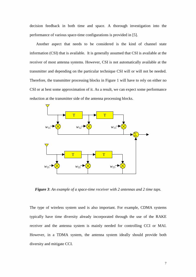
Previous work on MIMO antenna systems with antenna processing at the
transmitter and with a simple receive structure includes the transmit zero forcing
scheme [17], transmit MMSE and the filter bank method. The transmit zero forcing
scheme tries to pre-eliminate all the interference at the receiver. Some desired signal
power is sacrificed during the pre-eliminating process and therefore, the received
SNR may become very small. In contrast, the filter bank method provides a sub-
optimal solution for the problem that maximizes the minimum signal-to-interference-
plus-noise ratio (SINR) among all sub-channels. It must be also emphasized that none
of these methods can provide receive diversity. Some comparisons between these
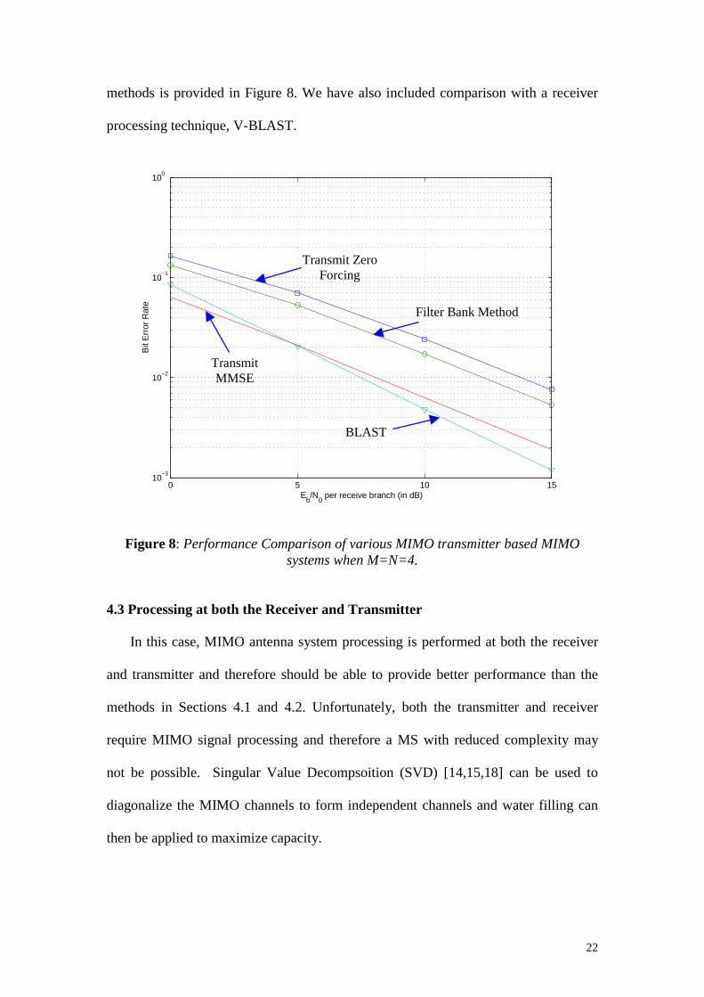
22
methods is provided in Figure 8. We have also included comparison with a receiver
processing technique, V-BLAST.
0 5 10 1510
−3
10−2
10−1
100
Eb/N
0 per receive branch (in dB)
Bit
Err
or R
ate
Figure 8: Performance Comparison of various MIMO transmitter based MIMO systems when M=N=4.
4.3 Processing at both the Receiver and Transmitter
In this case, MIMO antenna system processing is performed at both the receiver
and transmitter and therefore should be able to provide better performance than the
methods in Sections 4.1 and 4.2. Unfortunately, both the transmitter and receiver
require MIMO signal processing and therefore a MS with reduced complexity may
not be possible. Singular Value Decompsoition (SVD) [14,15,18] can be used to
diagonalize the MIMO channels to form independent channels and water filling can
then be applied to maximize capacity.
Transmit Zero Forcing
Filter Bank Method
BLAST
Transmit MMSE

23
5. Conclusions
In this paper, we have provided an overview of antenna systems for wireless
broadband communications. We have approached the overview by considering the
entire system with both an up and downlink system rather than concentrating on one
of the links only. We have then used this framework to consider systems with only
antenna systems at the BS, antenna systems at the MS and then antenna systems at
both the BS and MS. Overall, we can conclude that MIMO antenna systems can
provide tremendous capacity advantages without requiring extra bandwidth and
power.
References [1] J.H. Winters, “Optimum Combining in Digital Radio with Cochannel Interference”, IEEE J. Select.
Areas Commun., Vol. 2, No. 4, pp. 528-539, July 1984. [2] RG Vaughan and J Bach Andersen, “Antenna Diversity in Mobile Communications,” IEEE Trans.
Vehicular Technology, Vol. 36, No. 4, pp. 149-172, Nov. 1987. [3] J.H. Winters, “Smart Antennas for Wireless Systems,” IEEE Personal Commun. Mag., Vol 5, No.
1, pp. 23-27, Feb. 1998. [4] A. Lozano, F. R. Farrokhi and R. A. Valenzuela, “Lifting the Limits on High-Speed Wireless Data
Access Using Antenna Arrays,” IEEE Commun. Mag., Vol. 39, pp. 156-162, Sept. 2001 [5] J. C.L. Ng, K. B. Letaief and R. D. Murch, “Antenna Diversity Combining and Finite-Tap decision
Feedback Equalization for High-Speed Data Transmission,” IEEE J. Select. Areas Commun., Vol. 16, No. 8, pp. 1367-1375, Oct. 1998.
[6] S. M. Alamouti, “A simple transmit diversity technique for wireless communications,” IEEE J. Select. Areas Commun., Vol. 16, No. 8, pp. 1451-1458, Oct. 1998.
[7] Ye Li, J.C.chuang, and N.R. Sollenberger, “Transmitter diversity for OFDM systems and its impact on high-rate data wireless networks,” IEEE J. Sel. Areas Commun., Vol. 17, pp. 1233-43, July 1999.
[8] L-U Choi, K. B. Letaief, and R. D. Murch “MISO CDMA Transmission with Simplified Receiver for Wireless Communication Handsets,” IEEE Trans. Commun., Vol. 49, pp. 888-898, May 2001.
[9] Ying-Chang Liang, and Francois Chin, “Two Suboptimal Algorithms for Downlink Beamforming in FDD DS-CDMA Mobile Radio,” IEEE J. Select. Commun., July 2001
[10] Samuel CK Ko and R. D. Murch, “Compact Integrated Diversity Antenna for Wireless Communications,” IEEE Trans. Antennas and Propagation, Vol. 49, No. 6, pp. 954-960, June 2001.
[11] PB Wong and DC Cox, “Low Complexity Diversity Combining Algorithms and Circuit Architectures for Co-Channel Interference Cancellation and Frequency-Selective Fading Mitigation,” IEEE Trans. Commun., Vol. 44, No 9, pp. 1107-1116, Sept. 1996.
[12] Zhu Xu and RD Murch, “Performance Analysis of Maximum Likelihood Detection in a MIMO Antenna System”, To Appear in IEEE Transaction on Communications.
[13] G. D. Golden, C. J. Foschini, R. A. Valenzuela, P. W. Wolniansky, “Detection algorithm and initial laboratory results using V-BLAST space-time communication architecture,” IEE Electronics Letters, Vol.35, No.1, pp. 14-16, 7 Jan. 1999.
[14] J Bach Andersen, “Array gain and capacity for known random channels with multiple element arrays at both ends,” IEEE J. Select. Areas Commun., Vol. 18, Issue 11, pp. 2172–2178, Nov. 2000.
[15] W. K. Wong, R. D. Murch, and K. B. Letaief, “Optimizing Time and Space MIMO Antenna System for Frequency Selective Fading Channels,” IEEE J. Select. Areas Commun., Vol. 19, No. 7, pp. 1395-1407, July 2001.

24
[16] A. F. Naguib, V. Tarokh, N. Seshadri, and A. R. Calderbank, “A space-time coding modem for high data rate wireless communications,” IEEE J. Select. Areas Commun., Vol. 16, No. 8, pp. 1459-1478, Oct. 1998.
[17] H. Sampath, and A. J. Paulraj, ``Joint transmit and receive optimization for high data rate wireless communications using multiple antennas,'' Thirty-third Asilomar Conference on Signals, Systems, and Computers, 1999, vol. 1, pp.215-219.
[18] K.K. Wong, RS Cheng, K.B. Letaief and R.D. Murch, “Adaptive Antennas in the Mobile and Basestations in an OFDM/TDMA System,” IEEE Trans. Commun., Vol. 49, pp. 1-8, Jan. 2001.
[19] Gong Yi and K. B. Letaief, “Performance evaluation and analysis of space-time coding in unequalized multipath fading links,” IEEE Trans. Commun., Vol. 48, No. 11, Nov. 2000.

25
Biography of Ross Murch
Dr Ross MURCH is an Associate Professor in the Department of Electrical and Electronic Engineering at the Hong Kong University of Science and Technology. His current research interests include smart antenna systems, compact antenna design and propagation characterization for wireless communications. He has several US patents related to wireless communication, over 100 published papers and acts as a consultant for industry on occasions. In addition he is an editor for the IEEE Transactions on Wireless Communications and acts as a reviewer for several journals. He is the Chair of the Advanced Wireless Communications Systems Symposium at ICC 2002 and is also the founding Director of the Center for Wireless Information Technology at Hong Kong University of Science and Technology which was begun in August 1997. From August-December 1998 he was on sabbatical leave at Allgon Mobile Communications (manufactured 1 million antennas per week), Sweden and AT&T Research Labs, NJ, USA. Dr Ross Murch received his bachelors degree in Electrical and Electronic Engineering from the University of Canterbury, New Zealand where he graduated in 1986 with first class honors and was ranked first in his class. During his bachelors degree he was the recipient of several academic prizes including the John Blackett prize for engineering and also the Austral Standard Cables prize. In 1990 he completed his PhD, also in Electrical and Electronic Engineering at the University of Canterbury. During his PhD he was awarded a RGC and also a New Zealand Telecom scholarship. From 1990-92 he was a post doctorate fellow at the Department of Mathematics and Computer Science at Dundee University, Scotland. From 1992-1998 he was an Assistant Professor in the Department of Electrical and Electronic Engineering at the Hong Kong University of Science and Technology and since 1998 he has been an Associate Professor there. He is a senior member of IEEE, a Chartered Engineer and a member of IEE. In 1993 and 1996 he won an URSI young scientist and engineering teaching excellence appreciation awards respectively.

Biography of Khaled Ben Letaief
From 1990 to SElectronic Enginthe Center for Sethe Department & Technology (wireless and mMultiuser detecti
In January 2002TRANSACTIONSother journals iMMaaggaazziinnee, WireCommunicationsChair of the 199Australia. He isheld in HelsinkiSociety Technicaof Meeting and C
In addition to hicommitted to excfrom Purdue UnEngineering at HG. Gale Medal forecipient/year is
Khaled Ben Letaief received the BS degree with distinction in ElectricalEngineering from Purdue University at West Lafayette, Indiana, USA, inDecember 1984. He received the MS and Ph.D. Degrees in ElectricalEngineering from Purdue University, in August 1986, and May 1990,respectively. From January 1985 and as a Graduate Instructor in the School ofElectrical Engineering at Purdue University, he has taught courses in
26
eptember 1993, he was a faculty member in the Department of Electrical and eering at the University of Melbourne, Australia where he was also a member of nsor Signal and Information Systems. Since September 1993, he has been with
of Electrical & Electronic Engineering at the Hong Kong University of Science HKUST) where he is now a Professor. His current research interests include obile communications, OFDM, Space-time processing for wireless systems, on, Wireless multimedia communications, and CDMA systems.
, Dr. Letaief has been appointed the founding Editor-in-Chief of the IEEE ON WIRELESS COMMUNICATIONS. He has served on the editorial board of
ncluding the IEEE Transactions on Communications, IIEEEEEE CCoommmmuunniiccaattiioonnss less Personal Communications, and IEEE Journal on Selected Areas in – Wireless Series (as Editor-in-Chief). He served as the Technical Program 8 IEEE Globecom Mini-Conference on Communications Theory, held in Sydney, also the Co-Chair of the 2001 IEEE ICC Communications Theory Symposium, , Finland. He is currently serving as Vice-Chair of the IEEE Communications l Committee on Personal Communications. He is also currently the Vice chair onference Committee of the IEEE COMSOC Asia Pacific Board.
s active research activities, Professor Letaief has also been a dedicated teacher ellence in teaching and scholarship. He received the Mangoon Teaching Award
iversity in 1990; the Teaching Excellence Appreciation Award by the School of KUST in Spring 1995, Fall 1996, Fall 1997, and Spring 1999; and the Michael r Distinguished Teaching (Highest university-wide teaching award and only one
honored for his/her contributions).