ansys ls-dyna pc modeling of contact/impact with high … · ansys ls-dyna pc modeling of...
TRANSCRIPT

ANSYS LSANSYS LS--DYNA PC Modeling of Contact/Impact with High DYNA PC Modeling of Contact/Impact with High and Low Stiffness Materials in the Numerical Simulation of and Low Stiffness Materials in the Numerical Simulation of Nuclear Transportation Packages under 9 m Drop TestsNuclear Transportation Packages under 9 m Drop TestsMiguel Mattar Neto ([email protected])Carlos Alexandre de Jesus Miranda ([email protected])Gerson Fainer ([email protected])IPEN-CNEN/SP CEN – Nuclear Engineering Center

PRESENTATION TOPICS
• IPEN Overview
• Introduction
• The Transportation Package
• Finite Element Model
• Improving the contacts
• Conclusions

IPEN Overview
IPEN – CNEN/SP is the Nuclear and Energy Research Institute (Instituto de Pesquisas Energéticas e Nucleares)
IPEN is an autarchy of the estate of São Paulo, managed by the Brazilian Federal Government through CNEN, the Brazilian Nuclear Energy Commission, and associated to the University of São Paulo.
IPEN is organized in 12 centers and CEN, the Nuclear Engineering Center, is one of them.
The CEN Structural Mechanics Division has worked on the development of options to the storage of the spent fuel elements from the nuclear research reactor IEA-R1, located on IPEN, since 2000 which is supported by the IAEA, the International Atomic Energy Agency, through several research projects.
This work is included in the design of a dual purpose transportation and storage package for the spent fuel elements from the nuclear research reactor IEA-R1.
Introduction
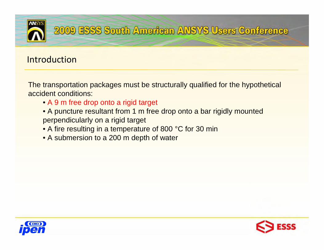
The transportation packages must be structurally qualified for the hypothetical accident conditions:
• A 9 m free drop onto a rigid target• A puncture resultant from 1 m free drop onto a bar rigidly mounted perpendicularly on a rigid target• A fire resulting in a temperature of 800 °C for 30 min• A submersion to a 200 m depth of water

Prescribed Tests
9 m
1 m
T = 800 °Ct = 30 min.
9 m drop test Penetration test
Thermal test Extended immersion test
200
m
t = 1 h
In the 9 m drop test numerical simulation, all the existing non-linearities related with the several contacts, material mechanical properties and geometry are considered.

The Transportation Package

The Transportation Package
Design criteriaDesign criteria: 21 MTR or 78 TRIGA, : 21 MTR or 78 TRIGA, max. weight 10 t, Type B fissile packagemax. weight 10 t, Type B fissile package
Design goalDesign goal::. 125 g in the internal basket. 125 g in the internal basket
Main partsMain parts::. Main body. Main body. Heads. Heads. Basket. Basket. Dampers (impact limiters). Dampers (impact limiters). Lids (In & External). Lids (In & External). Lead (biological shield). Lead (biological shield)

The Transportation Package
The package is a stainless steel cylinder with flat heads The package is a stainless steel cylinder with flat heads (the bottom one is welded and the upper one has flanges (the bottom one is welded and the upper one has flanges with threaded connections and internal basket (for the fuel with threaded connections and internal basket (for the fuel elements)elements)
-- It is surrounded by a biological shield of lead It is surrounded by a biological shield of lead -- it has also upper and lower wood dampers contained in it has also upper and lower wood dampers contained in stainless steel shells stainless steel shells

The Transportation Package

The Finite Element Model
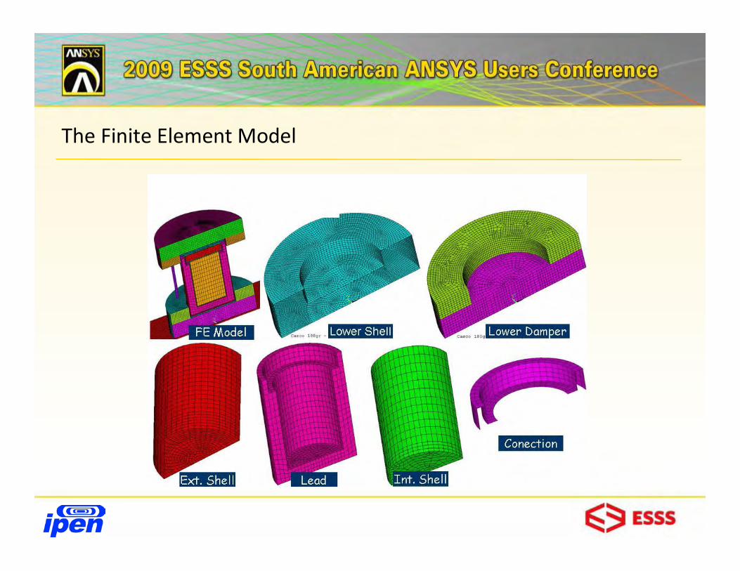
The Finite Element Model

The Finite Element Model

The Finite Element Model – Material Data
Package Part Material Dimensions
Lower shell stainless steel dia = 900 mm
Lower Damper wood (OSB) dia = 894 mm
Inner Shell stainless steel dia = 328 mm
Lead Lead
Outer Shell stainless steel dia = 492 mm
Upper Damper wood (OSB) dia = 894 mm
Upper shell stainless steel dia = 900 mm
Tie bars stainless steel dia = 30 mm

The Finite Element Model – Impact limiters material properties
Contacts, Materials Models & Loading
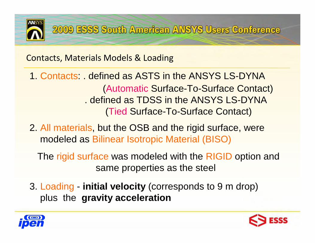
3. Loading - initial velocity (corresponds to 9 m drop)plus the gravity acceleration
2. All materials, but the OSB and the rigid surface, weremodeled as Bilinear Isotropic Material (BISO)
The rigid surface was modeled with the RIGID option and same properties as the steel
1. Contacts: . defined as ASTS in the ANSYS LS-DYNA (Automatic Surface-To-Surface Contact)
. defined as TDSS in the ANSYS LS-DYNA (Tied Surface-To-Surface Contact)
Improving the Contacts
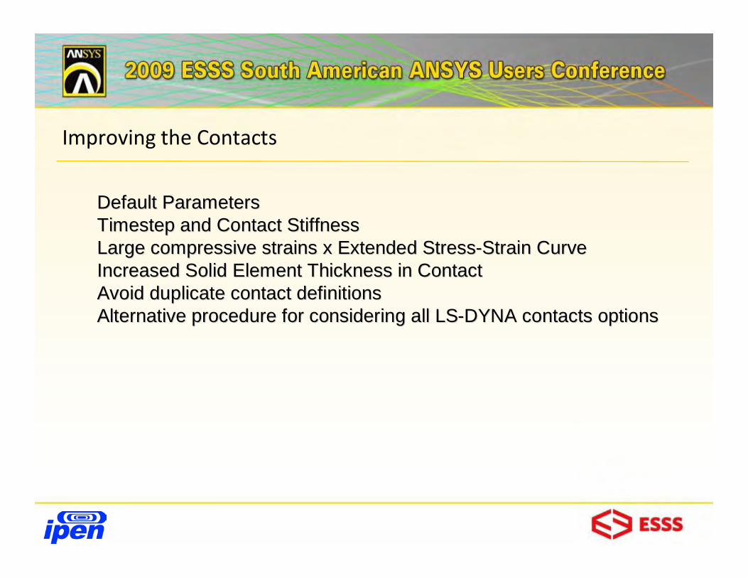
Default ParametersDefault ParametersTimestepTimestep and Contact Stiffness and Contact Stiffness Large compressive strains x Extended StressLarge compressive strains x Extended Stress--Strain CurveStrain CurveIncreased Solid Element Thickness in ContactIncreased Solid Element Thickness in ContactAvoid duplicate contact definitionsAvoid duplicate contact definitionsAlternative procedure for considering all LSAlternative procedure for considering all LS--DYNA contacts optionsDYNA contacts options
Improving the Contacts
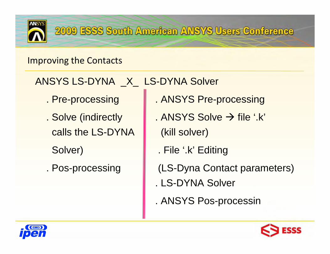
ANSYS LS-DYNA _X_ LS-DYNA Solver
. Pre-processing . ANSYS Pre-processing
. Solve (indirectly . ANSYS Solve file ‘.k’calls the LS-DYNA (kill solver)
Solver) . File ‘.k’ Editing
. Pos-processing (LS-Dyna Contact parameters). LS-DYNA Solver
. ANSYS Pos-processin

Improving the Contacts

Conclusions

Conclusions