andrew newman portfolio
DESCRIPTION
Academic/Professional PortfolioTRANSCRIPT


Design Perspectives / Portfolio 2013 / Volume 2.02

Andrew Newman | Selection of Work
Resume —
Professional Work —
Zimmer Gunsul Frasca /01
Perkins+Will /02
Perkins Eastman /03
Graduate Work —
Graduate Thesis /01
Parametric Lantern /02
Design/Build Studio /03
Re-Skinning Studio /04
SEC Studio /05
DESIGN EXPLORATIONS
01
02
3

Andrew NewmanAssociate AIA, LEED® AP BD+C
BiographyWith a critical eye for detail and professional experience from planning and design to assembly, I practice efficiency and communication in order to translate clients’ visions into final design solutions, presentations, and documents.
EducationUniversity of Cincinnati, DAAP | Cincinnati, OhioMaster of Architecture, August 2010 — May 2013
Maryland Institute College of Art | Baltimore, MarylandBachelor of Fine Arts, Environmental Design, August 2004 — May 2008
Mark Stempel ‘90 Thesis Prize for Design ExcellencePresidential & Trustee Scholarship Recipient
QualificationsSoftware Proficiency
Autodesk Revit 2014 Rhinoceros 5.0 Grasshopper DynamoRhinoceros 5.03D Studio Max 2014
Design Experience
Architectural VisualizationConcept DesignMasterplanningSchematic Design
Credentials/AffiliationsAmerican Institute of Architects, AssociateDesign Technology Leader, Commitee MemberPerkins+Will Research Journal 04.01 — Fall 2012LEED Accredited Professional, March 2009 — PresentUniversity of Cincinnati Health & Fitness OrganizationUniversity of Cincinnati Women’s Lacrosse, Volunteer
ExperienceBarber McMurry Architects | Knoxville, TNArchitectural Designer, February 2015 — PresentResponsible for the design, coordination, and technical development for commercial and healthcare projects from schematic design through construction administration. A majority of tasks have included BIM modeling, computer rendering, consultant coordination, construction documentation, and client relations. www.perkinswill.com
Perkins + Will | Atlanta, GAArchitectural Designer, May 2013 — PresentIntern Architect, January 2011 — September 2011
Staff support for design, consultant coordination and documentation of local K-12 education, corporate, civic and commercial projects. Project tasks have included BIM modeling & management, drafting, rendering as well as graphic illustrations. www.perkinswill.com
Zimmer Gunsul Frasca Architects | Portland, ORIntern Architect, March 2012 — September 2012
Full-time intern architect providing architectural support in the design, coordination and detailing of a 50 story residential tower in Vancouver, B.C. Project tasks involved BIM modeling and producing an architectural set of drawings for design development.www.zgf.com
Perkins Eastman Architects | New York, NYArchitectural Designer, August 2008 — April 2009
Full-time junior architect working among other architects, consultants and planners to develop design concepts for various international residential and commercial projects. www.perkinseastman.com
Ziger/Snead Architects | Baltimore, MDIntern Architect, January 2008 — April 2009
Part-time intern architect assisting architecture team members to develop construction documentation, site analysis, and illustrate design goals and representations for clients.www.zigersnead.com
Professional References available upon request
Phone513.680.8205
PorfolioClick here to view portfolio
Autodesk VasariAdobe IllustratorAdobe PhotoshopAdobe InDesignSketchupAutoCAD
Design DevelopmentConstruction DocumentationGraphic DesignMarketing

Andrew NewmanLEED® AP BD+C
BiographyWith a critical eye for detail and professional experience from planning and design to assembly, I practice efficiency and communication in order to translate clients’ visions into final design solutions, presentations, and documents.
EducationUniversity of Cincinnati, DAAP | Cincinnati, OhioMaster of Architecture, August 2010 — May 2013
Maryland Institute College of Art | Baltimore, MarylandBachelor of Fine Arts, Environmental Design, August 2004 — May 2008
Mark Stempel ‘90 Thesis Prize for Design ExcellencePresidential & Trustee Scholarship Recipient
QualificationsSoftware Proficiency
Autodesk Revit 2014 Rhinoceros 5.0 Grasshopper DynamoRhinoceros 5.03D Studio Max 2014
Design Experience
Architectural VisualizationConcept DesignMasterplanningSchematic Design
Credentials/AffiliationsDesign Technology Leader, Commitee MemberPerkins+Will Research Journal 04.01 — Fall 2012LEED Accredited Professional, March 2009 — PresentUniversity of Cincinnati Health & Fitness OrganizationUniversity of Cincinnati Women’s Lacrosse, Volunteer
ExperiencePerkins + Will | Atlanta, GAArchitectural Designer, May 2013 — PresentIntern Architect, January 2011 — September 2011
Staff support for design, consultant coordination and documentation of local K-12 education, corporate, civic and commercial projects. Project tasks have included BIM modeling & management, drafting, rendering as well as graphic illustrations. www.perkinswill.com
Zimmer Gunsul Frasca Architects | Portland, ORIntern Architect, March 2012 — September 2012
Full-time intern architect providing architectural support in the design, coordination and detailing of a 50 story residential tower in Vancouver, B.C. Project tasks involved BIM modeling and producing an architectural set of drawings for design development.www.zgf.com
Perkins Eastman Architects | New York, NYArchitectural Designer, August 2008 — April 2009
Full-time junior architect working among other architects, consultants and planners to develop design concepts for various international residential and commercial projects. www.perkinseastman.com
Ziger/Snead Architects | Baltimore, MDIntern Architect, January 2008 — April 2009
Part-time intern architect assisting architecture team members to develop construction documentation, site analysis, and illustrate design goals and representations for clients.www.zigersnead.com
Professional References available upon request
Phone513.680.8205
PorfolioClick here to view portfolio
Autodesk VasariAdobe IllustratorAdobe PhotoshopAdobe InDesignSketchupAutoCAD
Design DevelopmentConstruction DocumentationGraphic DesignMarketing


Professional Work
01/
Zimmer Gunsul Frasca /01
University of Oregon - Football Operations
Civic Center Residential Tower
Perkins+Will /03
BMW Executive Headquarters
Charleston Office Building
Sheet Music - Nashville Office Tower
Franklin School - CoStar Group
Ballou High School Replacement
IMF Renovation Competition
Perkins Eastman /08
Megastar Dubiotech Tower
Trump Resorts Serrenia Masterplan

Design Perspectives / Portfolio 2013 / Volume 2.0
CASANOVA CENTER PERFORMANCE CENTER
UNIVERSITY OF OREGON / Eugene, OR
During my internship at the services of Zimmer Gunsul Frasca I was lucky enough to spend a couple weeks working on the new Casanova football operations building for the University of Oregon. The new center included a 25,000 square-foot weight room, an enhanced grass football practice field as well as the addition of two new synthetic turf practice fields, and a full-service dining facility available to all University athletes, students and staff.
01/01
8

Andrew Newman | Selection of Work 9

Design Perspectives / Portfolio 2013 / Volume 2.0
Zimmer Gunsul FrascaUO Cassanova CenterEugene, OR / July 2012
Top: Site PlanLeft & Below: Building PhotographsRight: Building Elevations
B
D C
A
10

Andrew Newman | Selection of Work
A
A
A
A
A
B
B
C
C
C
C
D
D
D
D
E
E
B
C
D
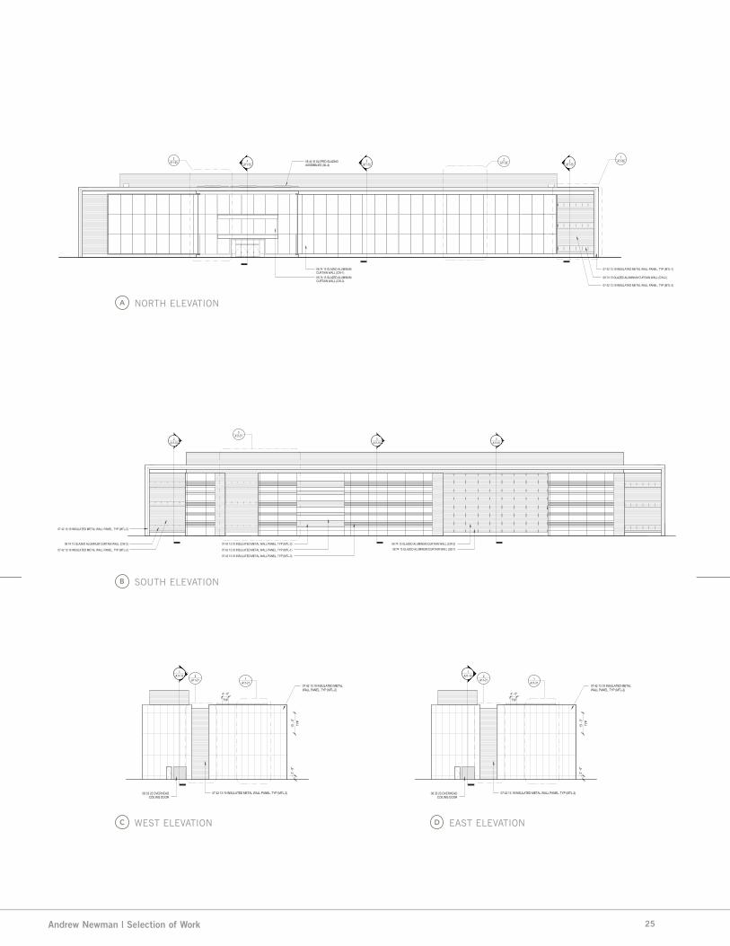
NORTH ELEVATION
SOUTH ELEVATION
EAST ELEVATION
WEST ELEVATION
UO CASANOVA CENTER
A TEACHING BOX
B BRIDGE
C OFFICE BAR
D WEIGHT ROOM
E MECHANICAL
11

Design Perspectives / Portfolio 2013 / Volume 2.0
A
B
C
DE
F
Zimmer Gunsul FrascaUO Cassanova CenterEugene, OR / July 2012
Top Left: Floor PlanTop: Building SectionRight: Building Photographs
UO CASANOVA CENTER
A ATHLETIC LOUNGE
B OFFICE
C HEAD COACH OFFICE
D WEIGHT ROOM
E LOCKER ROOM
F FIELD SUPPORT
AA
12

Andrew Newman | Selection of Work 13

Design Perspectives / Portfolio 2013 / Volume 2.014
Andrew Newman | Selection of Work
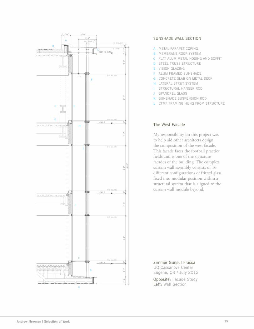
My responsibility on this project was to help aid other architects design the composition of the west facade. This facade faces the football practice fields and is one of the signature facades of the building. The complex curtain wall assembly consists of 16 different configurations of fritted glass fixed into modular position within a structural system that is aligned to the curtain wall module beyond.
Zimmer Gunsul FrascaUO Cassanova CenterEugene, OR / July 2012
Opposite: Facade StudyLeft: Wall Section
The West Facade
SUNSHADE WALL SECTION
A
B
C
D
E
F
G
H
I
J
K
L
A
BC
D E
F
G
H
I
J
K
C
L
H
METAL PARAPET COPING
MEMBRANE ROOF SYSTEM
FLAT ALUM METAL NOSING AND SOFFIT
STEEL TRUSS STRUCTURE
VISION GLAZING
ALUM FRAMED SUNSHADE
CONCRETE SLAB ON METAL DECK
LATERAL STRUT SYSTEM
STRUCTURAL HANGER ROD
SPANDREL GLASS
SUNSHADE SUSPENSION ROD
CFMF FRAMING HUNG FROM STRUCTURE
15

Design Perspectives / Portfolio 2013 / Volume 2.0
SURREY CITY DEVELOPMENT
CIVIC CENTER RESIDENTIAL TOWER / Vancouver, BC
Zimmer Gunsul Frasca was commissioned to design the exterior envelope of the 50-storey mixed-use hotel and residential project, 3 Civic Plaza. In the scope of work, ZGF was the responsible for the form and character of the facade.
The project will include a “boutique” hotel called the Civic Hotel. The hotel will feature 160 guest rooms, include meeting space to accommodate over 300 people and will be backed by an international reservation system. ZGF was also in charge of some parts of the hotel layouts as well.
Working within the envelope design team, I was in charge of modeling the skin of the tower in Revit, producing a set of 3 series sheets. These sheets included section, elevation, and detail drawings of numerous conditions around the facade. I also was in charge of coordinating the 3D model with various subcontractors and fabricators. Through this experience, I was able to expand my skill level in Revit, Photoshop and 3DS Max.
01/02
16

Andrew Newman | Selection of Work 17

Design Perspectives / Portfolio 2013 / Volume 2.0
Surrey Civic Center | South Elevation Surrey Civic Center | West Elevation
18

Andrew Newman | Selection of Work
Surrey Civic Center | PerspectivesTop: Lobby Rendering
Right: Plaza Rendering
19

Design Perspectives / Portfolio 2013 / Volume 2.0
GLAZING
CL
PLA
N D
IME
NS
ION
PLA
N D
IME
NS
ION
ALUMINUM WINDOWWALL MULLION
ALUMINUM FIN BELOW
STRUCTURAL SEALANT
ALUMINUM FIN - THERMALLYISOLATED FROM MULLION
SEALANT AND BACKER ROD
GLAZING
SUPPORT STEEL FOR WINDOWWALL SYSTEM -*OPTION A (VERTICALS ATEACH MULLION)
5/8"
4 1/2" 2"
EXTRUDED ALUMINUMCLADDING AT SUPPORT STEEL
*OPTION B (6" WINDOW WALLMULLIONS WITH INTERNAL STEELREINF.)
SE
CT
ION
DIM
EN
SIO
NS
EC
TIO
N D
IME
NS
ION
STRUCTURAL SEALANT
SPANDREL GLASS
METAL BACKPAN
EXTRUDED ALUMINUM FIN
MEMBRANE
TOP OF CONCRETE SLAB
EXTRUDED ALUMINUM TRIMFLASHING
CURTAIN WALL INSULATION
FIXED GLAZING
ALUMINUM WINDOW WALL SYSTEM
TOP OF MULLION & FIN
EXTRUDED ALUMINUM FIN
ALIGN VERTICAL FIN ANDALUMINUM TRIM
RAISED ACCESSFLOOR
1' -
0"
1' -
0"
10 1
/2"
TOP OF RAISED FLOOR
METAL STUD WALL
VERTICAL SUPPORTSTEEL FOR WINDOWWALL SYSTEM INMULLION BEYOND
ALUMINUM WINDOW WALLSYSTEM
FIXED GLAZING
VENT AIR FLOW
CONTINUOUS ALUMINUMLOUVER - GLAZED INTOWINDOW WALL
EXTRUDED ALUMINUM FIN -ALIGN WITH VERTICAL FIN
INSULATED AWNING DOORFOR WINDOW VENTING
6 3/
4"
CL
SE
CT
ION
DIM
EN
SIO
NS
EC
TIO
N D
IME
NS
ION
STRUCTURAL SEALANT
SPANDREL GLASS
METAL BACKPAN
EXTRUDED ALUMINUM FIN
MEMBRANE
TOP OF CONCRETE SLAB
EXTRUDED ALUMINUM TRIMFLASHING
CURTAIN WALL INSULATION
FIXED GLAZING
ALUMINUM WINDOW WALL SYSTEM
TOP OF RAISED FLOOR
EXTRUDED ALUMINUM FIN
ALIGN VERTICAL FIN ANDALUMINUM TRIM
RAISED ACCESSFLOOR
1' -
0"
1' -
0"
10 1
/2"
TOP OF RAISED FLOOR
METAL STUD WALL
VERTICAL SUPPORTSTEEL FOR WINDOWWALL SYSTEM INMULLION BEYOND
ALUMINUM WINDOW WALLSYSTEM
GLAZING
VENT AIR FLOW
CONTINUOUS ALUMINUMLOUVER - GLAZED INTOWINDOW WALL
INSULATED AWNING DOORFOR WINDOW VENTING
ZERO SIGHT LINEAWNING WINDOW
4 1/2" 2"
EXPRESSED ALUMINUM MULLION ATAWNING WINDOW
3/4"
SE
CT
ION
DIM
EN
SIO
NS
EC
TIO
N D
IME
NS
ION
AWNING WINDOW
ALUMINUM WINDOWWALL SYSTEM
FIXED WINDOW
VERTICAL SUPPORTSTEEL FOR WINDOWWALL SYSTEM INMULLION BEYOND
4 1/2" 2"
3/4"
EXPRESSED ALUMINUMMULLION AT AWNING WINDOW
ZERO SIGHT LINE AWNINGWINDOW
CL
PLA
N D
IME
NS
ION
PLA
N D
IME
NS
ION
ALUMINUM WINDOWWALL MULLION
ALUMINUM FIN BELOW
STRUCTURAL SEALANT
ALUMINUM FIN - THERMALLYISOLATED FROM MULLION
SEALANT AND BACKER ROD
FIXED GLAZING
SUPPORT STEEL FOR WINDOWWALL SYSTEM -*OPTION A (VERTICALS ATEACH MULLION)
5/8"
4 1/2" 2"
EXTRUDED ALUMINUMCLADDING AT SUPPORT STEEL
*OPTION B (6" WINDOW WALLMULLIONS WITH INTERNAL STEELREINF.)
3/16
"
SILL BELOW
3/4"
EXPRESSED ALUMINUMMULLION AT AWNING WINDOW
Unit 235, 11300 NO. 5 ROAD, RICHMOND, BC V7A 5J7
TEL: (604) 272-1477 FAX: (604) 272-1471 EMAIL: [email protected]
WEB: www.cotterarchitects.com
PROJECT:
CLIENT:
DRAWN
CHECKED:
SCALE:
JOB No:
DATE:
SHEET TITLE:
SEAL:
DRAWING NO: REV:
COPYRIGHT RESERVED. THIS PLAN AND DESIGN ARE, AND AT ALL TIMES REMAINTHE EXCLUSIVE PROPERTY OF PATRICK COTTER ARCHITECT INC. AND CANNOT BEUSED OR REPRODUCED WITHOUT THE ARCHITECT'S WRITTEN CONSENT.
ISSUED:
PROJECT ADDRESS:
--
--
--
--
--
--
--
--
--
--
--
RZ
MARK
29/06/12
07/06/12
10/05/12
19/04/12
15/03/12
08/03/12
21/02/12
09/02/12
27/01/12
20/01/12
13/01/12
23/12/11
DD/MM/YY
100% DESIGN DEVELOPMENT
ADVISORY DESIGN PANEL SUBMISSION #3
ADVISORY DESIGN PANEL SUBMISSION #2
ISSUED TO CONSULTANTS
ADVISORY DESIGN PANEL SUBMISSION
DEVELOPMENT PERMIT APPLICATION
PROGRESS SET SENT TO CITY
PROGRESS SET
PROGRESS SET
PROGRESS SET
PROGRESS SET FOR COORDINATION
REZONING & SUBDIVISION APPLICATION
DESCRIPTION
NOTES:
NOT FORCONSTRUCTION
3" = 1'-0"
2/4/
2013
6:5
7:09
PM A-405
DETAILS,EXTERIOR
June 2012
SCD
Checker
Author
Surrey CentreMixed-Use Development
Surrey Tower DevelopmentManagement Corporation
103A Avenue & City Parkway, Surrey BC
3" = 1'-0"A-4051 OFFICE - VERTICAL MULLION
3" = 1'-0"A-4052 OFFICE - HEAD AND SILL (FIXED)
3" = 1'-0"A-4054 OFFICE - AWNING HEAD
3" = 1'-0"A-4053 OFFICE - INTERMEDIATE HORIZ MULL W/ BUTT AWNING SILL
3" = 1'-0"A-4055 OFFICE - VERTICAL MULLION W/ AWNING JAMB
PRODUCED BY AN AUTODESK STUDENT PRODUCT
PR
OD
UC
ED
BY
AN
AU
TOD
ES
K S
TUD
EN
T PR
OD
UC
T
PRODUCED BY AN AUTODESK STUDENT PRODUCT
PR
OD
UC
ED
BY
AN
AU
TOD
ES
K S
TUD
EN
T P
RO
DU
CT
Office Facade West - Enlarged Elevation | Enlarged Plan
Office Facade West - Cut-away SectionOffice Facade West - Sill Detail
Office Facade West - Wall Section
20

Andrew Newman | Selection of Work
LEVEL 16125.39
LEVEL 17128.35
LEVEL 18131.31
12 13
3A-316
1 112
1 1
112
1 1
1
2
2
2
2
1
1
1
1
2
2
2
2
2 1
1
1
1
2
2 1
2
2 1 1 1
ALUM WINDOW WALL (SERIES 3)
COMPOSITE ALUMINUM PANEL
ALUM WINDOW WALL (SERIES 2)
GLAZING - SEE SCHEDULE
AWNING WINDOW, TYP.
AWNING WINDOW, TYP.
WITH BUTT GLAZED VERTICALJOINTS AND 3" DEEP HORIZONTALEXTRUDED ALUMINUM FINS
2
A-401
3
A-401
1
A-406
3
A-406
2
A-406
5
A-406
2
2
2
G
E
D
12 1319
3' - 3"
2'-0"
4'-8"
2'-0"
1'-6 3/8"
4'-1
7/8
"
11 1/2"
LEVEL 16125.39
LEVEL 17128.35
LEVEL 18131.31
9'-8
1/2
"9'
-8 1
/2"
1'-0
"1'
-10
7/8"
2'-1
5/8
"2'
-1 5
/8"
2'-0
3/8
"6"
BATT INSULATION
Unit 235, 11300 NO. 5 ROAD, RICHMOND, BC V7A 5J7
TEL: (604) 272-1477 FAX: (604) 272-1471 EMAIL: [email protected]
WEB: www.cotterarchitects.com
PROJECT:
CLIENT:
DRAWN
CHECKED:
SCALE:
JOB No:
DATE:
SHEET TITLE:
SEAL:
DRAWING NO: REV:
COPYRIGHT RESERVED. THIS PLAN AND DESIGN ARE, AND AT ALL TIMES REMAINTHE EXCLUSIVE PROPERTY OF PATRICK COTTER ARCHITECT INC. AND CANNOT BEUSED OR REPRODUCED WITHOUT THE ARCHITECT'S WRITTEN CONSENT.
ISSUED:
PROJECT ADDRESS:
--
--
--
--
--
--
--
--
--
--
--
RZ
MARK
29/06/12
07/06/12
10/05/12
19/04/12
15/03/12
08/03/12
21/02/12
09/02/12
27/01/12
20/01/12
13/01/12
23/12/11
DD/MM/YY
100% DESIGN DEVELOPMENT
ADVISORY DESIGN PANEL SUBMISSION #3
ADVISORY DESIGN PANEL SUBMISSION #2
ISSUED TO CONSULTANTS
ADVISORY DESIGN PANEL SUBMISSION
DEVELOPMENT PERMIT APPLICATION
PROGRESS SET SENT TO CITY
PROGRESS SET
PROGRESS SET
PROGRESS SET
PROGRESS SET FOR COORDINATION
REZONING & SUBDIVISION APPLICATION
DESCRIPTION
NOTES:
NOT FORCONSTRUCTION
1/2" = 1'-0"
2/4/
2013
6:5
5:20
PM A-316
ENLARGEDELEVATION / WALLSECTION - HOTELWEST
June 2012
SCD
Checker
Author
Surrey CentreMixed-Use Development
Surrey Tower DevelopmentManagement Corporation
103A Avenue & City Parkway, Surrey BC 1/2" = 1'-0"A-316
1 ENLARGED ELEVATION - HOTEL WEST
1/2" = 1'-0"A-3162 PLAN - HOTEL WEST
1/2" = 1'-0"A-3163 WALL SECTION - HOTEL WEST1
PRODUCED BY AN AUTODESK STUDENT PRODUCT
PR
OD
UC
ED
BY
AN
AU
TOD
ES
K S
TUD
EN
T PR
OD
UC
T
PRODUCED BY AN AUTODESK STUDENT PRODUCT
PR
OD
UC
ED
BY
AN
AU
TOD
ES
K S
TUD
EN
T P
RO
DU
CT
LEVEL 16125.39
LEVEL 17128.35
LEVEL 18131.31
12 13
3A-316
1 112
1 1
112
1 1
1
2
2
2
2
1
1
1
1
2
2
2
2
2 1
1
1
1
2
2 1
2
2 1 1 1
ALUM WINDOW WALL (SERIES 3)
COMPOSITE ALUMINUM PANEL
ALUM WINDOW WALL (SERIES 2)
GLAZING - SEE SCHEDULE
AWNING WINDOW, TYP.
AWNING WINDOW, TYP.
WITH BUTT GLAZED VERTICALJOINTS AND 3" DEEP HORIZONTALEXTRUDED ALUMINUM FINS
2
A-401
3
A-401
1
A-406
3
A-406
2
A-406
5
A-406
2
2
2
G
E
D
12 1319
3' - 3"
2'-0"
4'-8"
2'-0"
1'-6 3/8"
4'-1
7/8
"
11 1/2"
LEVEL 16125.39
LEVEL 17128.35
LEVEL 18131.31
9'-8
1/2
"9'
-8 1
/2"
1'-0
"1'
-10
7/8"
2'-1
5/8
"2'
-1 5
/8"
2'-0
3/8
"6"
BATT INSULATION
Unit 235, 11300 NO. 5 ROAD, RICHMOND, BC V7A 5J7
TEL: (604) 272-1477 FAX: (604) 272-1471 EMAIL: [email protected]
WEB: www.cotterarchitects.com
PROJECT:
CLIENT:
DRAWN
CHECKED:
SCALE:
JOB No:
DATE:
SHEET TITLE:
SEAL:
DRAWING NO: REV:
COPYRIGHT RESERVED. THIS PLAN AND DESIGN ARE, AND AT ALL TIMES REMAINTHE EXCLUSIVE PROPERTY OF PATRICK COTTER ARCHITECT INC. AND CANNOT BEUSED OR REPRODUCED WITHOUT THE ARCHITECT'S WRITTEN CONSENT.
ISSUED:
PROJECT ADDRESS:
--
--
--
--
--
--
--
--
--
--
--
RZ
MARK
29/06/12
07/06/12
10/05/12
19/04/12
15/03/12
08/03/12
21/02/12
09/02/12
27/01/12
20/01/12
13/01/12
23/12/11
DD/MM/YY
100% DESIGN DEVELOPMENT
ADVISORY DESIGN PANEL SUBMISSION #3
ADVISORY DESIGN PANEL SUBMISSION #2
ISSUED TO CONSULTANTS
ADVISORY DESIGN PANEL SUBMISSION
DEVELOPMENT PERMIT APPLICATION
PROGRESS SET SENT TO CITY
PROGRESS SET
PROGRESS SET
PROGRESS SET
PROGRESS SET FOR COORDINATION
REZONING & SUBDIVISION APPLICATION
DESCRIPTION
NOTES:
NOT FORCONSTRUCTION
1/2" = 1'-0"
2/4/
2013
6:5
5:20
PM A-316
ENLARGEDELEVATION / WALLSECTION - HOTELWEST
June 2012
SCD
Checker
Author
Surrey CentreMixed-Use Development
Surrey Tower DevelopmentManagement Corporation
103A Avenue & City Parkway, Surrey BC 1/2" = 1'-0"A-316
1 ENLARGED ELEVATION - HOTEL WEST
1/2" = 1'-0"A-3162 PLAN - HOTEL WEST
1/2" = 1'-0"A-3163 WALL SECTION - HOTEL WEST1
PRODUCED BY AN AUTODESK STUDENT PRODUCT
PR
OD
UC
ED
BY
AN
AU
TOD
ES
K S
TUD
EN
T PR
OD
UC
T
PRODUCED BY AN AUTODESK STUDENT PRODUCT
PR
OD
UC
ED
BY
AN
AU
TOD
ES
K S
TUD
EN
T P
RO
DU
CT
GLAZING
ALUMINUM WINDOW WALL
SYSTEM
GLAZING
ALUMINUM WINDOW WALL
SYSTEM
COMPOSITE ALUMINUM PANEL
RIGID INSULATION
WATER / VAPOR BARRIER
COMPOSITE ALUMINUM
PANEL
4"
4 1/2" 2"
SE
CT
ION
DIM
EN
SIO
NS
EC
TIO
N D
IME
NS
ION
COMPOSITE ALUMINUM PANEL
WEEP
WEEP
METAL FLASHING
WATER / VAPOR BARRIER -
LAP ONTO METAL FLASHING
4 1/2" 2"
2 1/2" 2"
4 1/2"
EXTRUDED ALUMINUM
WINDOW SILL EXTENSION
GLAZED IN "TRICKLE VENT"
10 3
/4"
ROLLER SHADE
EXTRUDED ALUMINUM
CLOSURE
5"
5"
3/4
"3/4
"
6 1
/4"
10 1
/2"
6 5/8"
GLAZING
ALUMINUM WINDOW WALL
SYSTEM
GLAZING
ALUMINUM WINDOW WALL
SYSTEM
SEALANT AND BACKER ROD
COMPOSITE ALUMINUM PANEL
RIGID INSULATION
WATER / VAPOR BARRIER
COMPOSITE ALUMINUM
PANEL
4"
4 1/2" 2"
4 1/2"
TOP OF FLOOR SLAB
SE
CT
ION
DIM
EN
SIO
NS
EC
TIO
N D
IME
NS
ION
COMPOSITE ALUMINUM
PANEL
10 3
/4"
2"
ROLLER SHADE"
EXTRUDED ALUMINUM
WINDOW SILL EXTENSION
EXTRUDED ALUMINUM
CLOSURE
5"
5"
INSULATING SPANDREL
GLASS
CL
PLA
N D
IME
NS
ION
PLA
N D
IME
NS
ION
EXTRUDED ALUMINUM
MULLION EXTENSION
INSULATING SPANDREL
GLASS
ALUMINUM WINDOW
WALL MULLION
2"4 1/2"
CONCRETE COLUMN
METAL STUD PARTITION
AWNING WINDOW
CL
SE
CT
ION
D
IME
NS
ION
SE
CT
ION
D
IME
NS
ION
AWNING WINDOW
ALUMINUM WINDOW
WALL MULLION
4 1/2"
AWNING WINDOW
CL
PLA
N D
IME
NS
ION
PLA
N D
IME
NS
ION
EXTRUDED ALUMINUM
MULLION EXTENSION
GLAZING
ALUMINUM WINDOW
WALL MULLION
2"4 1/2"
FORMED ALUMINUM PANEL
WITH CONCEALED FASTENERS
RIGID INSULATION
AIR / WATER / VAPOR
BARRIER
SE
CT
ION
DIM
EN
SIO
NS
EC
TIO
N D
IME
NS
ION
1/4" PREFINISHED ALUMINUM
CHANNEL WITH CONCEALED
FASTENERS
WEEP
METAL STUD PARTITION
DEFLECTION HEAD
PREFINISHED ALUMINUM
FLASHING / DEFLECTION
HEAD
GALVANIZED METAL 'Z' FURRING
- ALIGN WITH METAL STUDS
EXPOSED CONCRETE SLAB
FINISH FLOOR
TOP OF FLOOR SLAB &
ALUMINUM CHANNEL
FORMED ALUMINUM PANEL
WITH CONCEALED
FASTENERS
SEALANT AND BACKER
ROD
8"
1"
1/2
"1/2
"
5"
Unit 235, 11300 NO. 5 ROAD, RICHMOND, BC V7A 5J7
TEL: (604) 272-1477 FAX: (604) 272-1471 EMAIL: [email protected]
WEB: www.cotterarchitects.com
PROJECT:
CLIENT:
DRAWN
CHECKED:
SCALE:
JOB No:
DATE:
SHEET TITLE:
SEAL:
DRAWING NO: REV:
COPYRIGHT RESERVED. THIS PLAN AND DESIGN ARE, AND AT ALL TIMES REMAINTHE EXCLUSIVE PROPERTY OF PATRICK COTTER ARCHITECT INC. AND CANNOT BEUSED OR REPRODUCED WITHOUT THE ARCHITECT'S WRITTEN CONSENT.
ISSUED:
PROJECT ADDRESS:
--
--
--
--
--
--
--
--
--
--
--
RZ
MARK
29/06/12
07/06/12
10/05/12
19/04/12
15/03/12
08/03/12
21/02/12
09/02/12
27/01/12
20/01/12
13/01/12
23/12/11
DD/MM/YY
100% DESIGN DEVELOPMENT
ADVISORY DESIGN PANEL SUBMISSION #3
ADVISORY DESIGN PANEL SUBMISSION #2
ISSUED TO CONSULTANTS
ADVISORY DESIGN PANEL SUBMISSION
DEVELOPMENT PERMIT APPLICATION
PROGRESS SET SENT TO CITY
PROGRESS SET
PROGRESS SET
PROGRESS SET
PROGRESS SET FOR COORDINATION
REZONING & SUBDIVISION APPLICATION
DESCRIPTION
NOTES:
NOT FORCONSTRUCTION
3" = 1'-0"
2/4/
2013
6:5
7:14
PM A-406
DETAILS,EXTERIOR
June 2012
SCD
Checker
Author
Surrey CentreMixed-Use Development
Surrey Tower DevelopmentManagement Corporation
103A Avenue & City Parkway, Surrey BC
3" = 1'-0"A-4062 HOTEL - HEAD AND SILL
3" = 1'-0"A-4064 HOTEL - EXTENDED SLAB
3" = 1'-0"A-4065 HOTEL - VERTICAL MULLION AT SPANDREL
3" = 1'-0"A-4061 HOTEL - INTERMEDIATE HORIZ MULLION
3" = 1'-0"A-4063 HOTEL - AWNING JAMB
3" = 1'-0"A-4066 METAL PANEL AT FLOOR LINE
PRODUCED BY AN AUTODESK STUDENT PRODUCT
PR
OD
UC
ED
BY
AN
AU
TOD
ES
K S
TUD
EN
T PR
OD
UC
T
PRODUCED BY AN AUTODESK STUDENT PRODUCT
PR
OD
UC
ED
BY
AN
AU
TOD
ES
K S
TUD
EN
T P
RO
DU
CT
Hotel Facade West - Enlarged Elevation | Enlarged Plan
Hotel Facade West - Cut-away SectionHotel Facade West - Sill Detail
Hotel Facade West - Wall Section
21

Design Perspectives / Portfolio 2013 / Volume 2.0
01/03
BMW EXECUTIVE OFFICES
UNITED STATES BMW HQ / Spartensburg, SC
The BMW Executive Office project is a 3-story, approximately 68,000 sf office building located on BMW’s main campus in Spartensburg, SC. The concept for the building was aimed to be arfully systemmatic and boldly reflective. The biggest challange of this project was to integrate the company’s graphic standards as a part of the branded environment vision.
The exterior enclosure of the building will consist of three distinct metal wall panels. On the north side of the building, we used a custom two sided structurally glazed curtain wall with steel vertical T’s and structural glass horizontals.
Working with another architect, my responsibilities were focused on taking the lead for all design decisions, building and managing the BIM model, coordinating the documents with various consultants and drawing all of the elements of the enclosure and core of the building.
22

Andrew Newman | Selection of Work 23

Design Perspectives / Portfolio 2013 / Volume 2.0
Perkins+WillBMW Executive OfficesSpartensburg, SC / October 2014
BMW EXECUTIVE OFFICES
A LOBBY
B CONFERENCE ROOM
C TEA ROOM
D SMALL CONFERENCE
E TERRACE
F OFFICE
A B
A B
B
D C
A
A
A
BUILDING SECTION A-A
BUILDING SECTION B-B
GROUND FLOOR PLAN
A
B
D
C
C
C
F
E
F
F
24
Andrew Newman | Selection of Work
1A11-10
A11-211A11-21
2
TYP
4' - 0"
2' - 6
"
08 33 23 OVERHEADCOILING DOOR
TYP
13'-
0"
07 42 13.19 INSULATED METAL WALL PANEL, TYP (MTL-2)
07 42 13.19 INSULATED METAL WALL PANEL, TYP (MTL-2)
1A11-10
A11-211A11-21
2
TYP
4' - 0"
2' - 6
"
08 33 23 OVERHEADCOILING DOOR
TYP
13'-
0"
07 42 13.19 INSULATED METAL WALL PANEL, TYP (MTL-2)
07 42 13.19 INSULATED METAL WALL PANEL, TYP (MTL-2)
3A11-10
2A11-10
A11-201
A11-202
A11-203
4A11-10
08 74 13 GLAZED ALUMINUMCURTAIN WALL (CW-1)08 74 13 GLAZED ALUMINUMCURTAIN WALL (CW-3)
07 42 13.19 INSULATED METAL WALL PANEL, TYP (MTL-1)
08 74 13 GLAZED ALUMINUM CURTAIN WALL (CW-2 )
07 42 13.19 INSULATED METAL WALL PANEL, TYP (MTL-2)
08 44 33 SLOPED GLAZINGASSEMBLIES (GL-4)
3A11-10
2A11-10
A11-213
4A11-10
07 42 13.19 INSULATED METAL WALL PANEL, TYP (MTL-2)
08 74 13 GLAZED ALUMINUM CURTAIN WALL (CW-2)
07 42 13.19 INSULATED METAL WALL PANEL, TYP (MTL-2)
07 42 13.19 INSULATED METAL WALL PANEL, TYP (MTL-3)
07 42 13.19 INSULATED METAL WALL PANEL, TYP (MTL-1)
07 42 13.19 INSULATED METAL WALL PANEL, TYP (MTL-2) 08 74 13 GLAZED ALUMINUM CURTAIN WALL (CW-2)08 74 13 GLAZED ALUMINUM CURTAIN WALL (SS-1)
B
A
C D
SOUTH ELEVATION
NORTH ELEVATION
WEST ELEVATION EAST ELEVATION
25

Design Perspectives / Portfolio 2013 / Volume 2.0
Perkins+WillBMW Executive OfficesSpartensburg, SC / October 2014
26

Andrew Newman | Selection of Work 27

Design Perspectives / Portfolio 2013 / Volume 2.0
CHARLESTON OFFICE BUILDING
Gateway Development Group / Charleston, SC
01/04
Perkins+Will was commissioned to design the first of four new office buildings for a new development located on the west side of Charleston, SC. This building contains approximately 150,000 square feet of office space including 20,000 square feet of retail space on the first level. The setback of the building at seventh level allows the roof of the structure below to become an occupied exterior roof garden / terrace along the North and East perimeter.
The exterior enclosure of the building will consist of three distinct aluminum curtain wall systems with six laminated glass types. On the North facade, the curtain wall system will be a highly articulated four sided capless system with vertical extruded aluminum fins.
As a lead designer of this project, my responsibilities were to build and manage the BIM model, coordinate amongst the consultants and document all of the elements of the enclosure and core of the building.
28

Andrew Newman | Selection of Work
Perkins+WillCharleston Office Building
Charleston, SC / August 2014
Top: Southeast Perspective
29

Design Perspectives / Portfolio 2013 / Volume 2.0
Perkins+WillCharleston Office BuildingCharleston, SC / August 2014
Top: Masterplan PerspectiveBelow: Building SectionOpposite: Perspectives + Site Plan
30

Andrew Newman | Selection of Work 31

Design Perspectives / Portfolio 2013 / Volume 2.0
Perkins+WillCharleston Office BuildingCharleston, SC / August 2014
Top: Detail PerspectiveOpposite: Curtain Wall Detail
32

Andrew Newman | Selection of Work
B Enlarged Plan - South Facade
A Enlarged Elevation - South Facade
33

Design Perspectives / Portfolio 2013 / Volume 2.0
01/05
34

Andrew Newman | Selection of Work
SHEET MUSIC - NASHVILLE OFFICE TOWER
Highwoods Development Group / Nashville, TN
Located in the heart of Nashville’s civic center, Sheet Music is a 30 story office building that sits adjacent to the music city plaza. The single tenant office building contains approximately 840,000 SF including ten double helix parking levels and 10,000 SF of retail at its base. The concept for the enclosure system represents a theme of sheet music with four curtain wall planes, adding a new modern addition to the Nashville skyline.
The exterior enclosure of the building will consist of two distinct aluminum curtain wall systems. On the north and south sides of the building, the wall system will consist of clear, capless glazing system with terrace setbacks at the top of the north and south facade. On the east and west facade, the curtain wall system will be a highly articulated four sided capless system with vertical extruded aluminum fins.
Working amongst other designers, my responsibilities were focused on building and managing the BIM model, coordinate with various the consultants and document all of the elements of the enclosure and core of the building.
35

Design Perspectives / Portfolio 2013 / Volume 2.0
Perkins+WillNashville Office TowerNashville, TN / October 2014
Top: Model PhotographsOpposite: Model Photographs
36

Andrew Newman | Selection of Work 37

Design Perspectives / Portfolio 2013 / Volume 2.0
Perkins+WillNashville Office ToweNashville, TN / October 2014
Top: Detail RenderingOpposite: Perspective Rendering
38

Andrew Newman | Selection of Work 39

Design Perspectives / Portfolio 2013 / Volume 2.0
A
B
Ground Floor Plan - Parking Ingress/Egress
Typical Parking Plan
40
Andrew Newman | Selection of Work
C
D
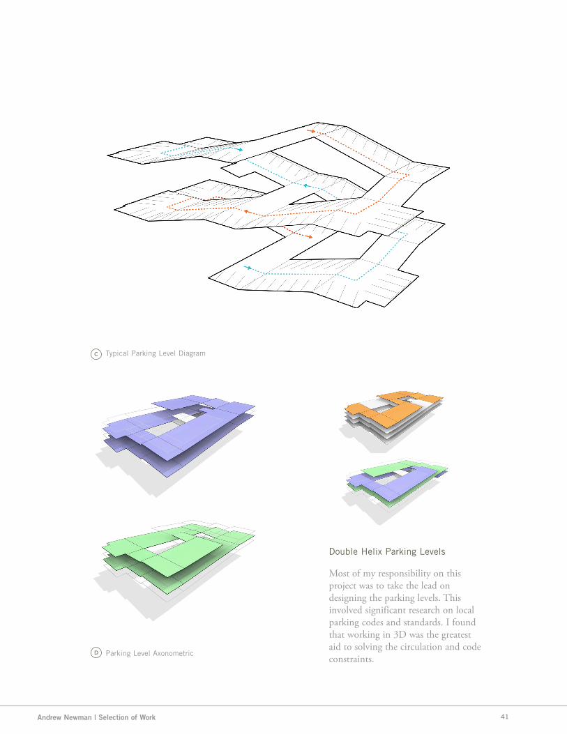
Typical Parking Level Diagram
Parking Level Axonometric
Most of my responsibility on this project was to take the lead on designing the parking levels. This involved significant research on local parking codes and standards. I found that working in 3D was the greatest aid to solving the circulation and code constraints.
Double Helix Parking Levels
41

Design Perspectives / Portfolio 2013 / Volume 2.0
FRANKLIN SCHOOL - COSTAR
COSTAR REAL ESTATE GROUP / Washington, DC
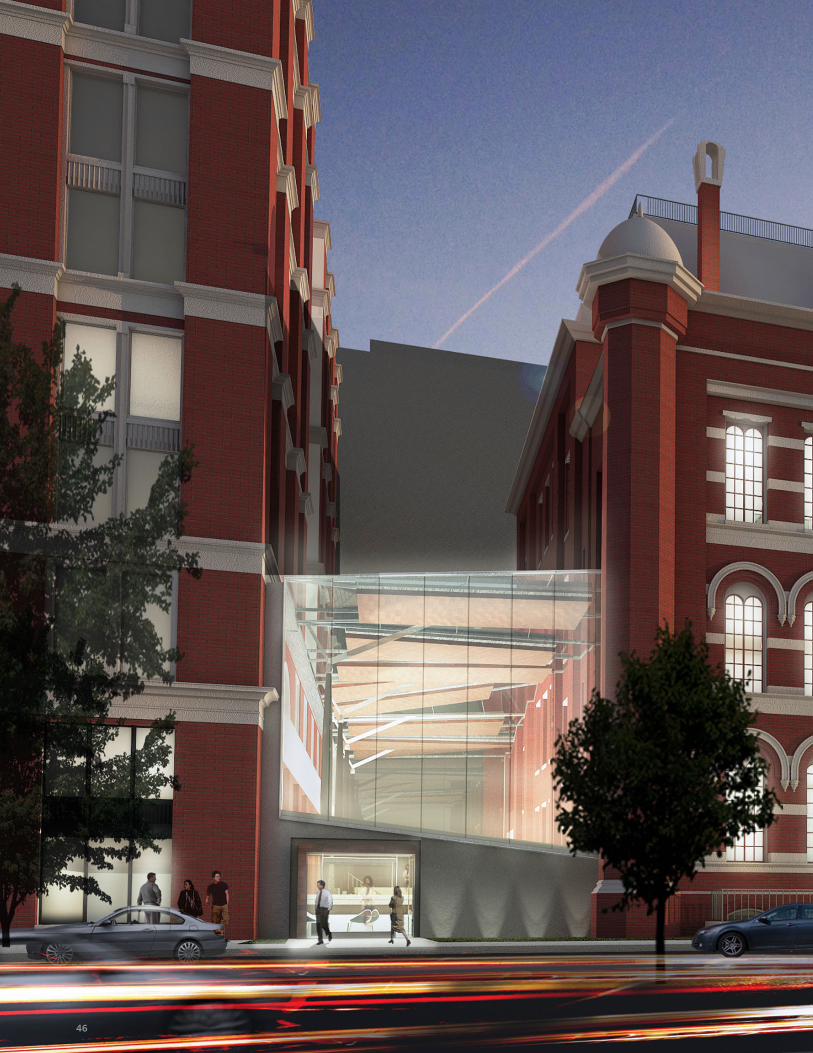
Located in the heart of Washington, DC, the Franklin School is a historic landmark that was originally was purposed as a school in the early 1900’s. The landmark sits on the edge of one of the city’s largest parks, Franklin Square, and resides in the middle of central business district.
Perkins+Will was commissioned by the Costar group to develop a proposal for reuse of the building including a small addition in-between the Franklin School and its neighboring building.
Working with the design team, I was in charge of generating the BIM model of the existing building, as well as proposed. I also produced the entire visualization package, rendering the model in 3DS Mac and Photoshop.
Other duties included coordinating the 3D model with various subcontractors and fabricators. Through this experience, I was able to expand my skill level in Revit, Photoshop and 3DS Max.
01/06
42

Andrew Newman | Selection of Work 43

Design Perspectives / Portfolio 2013 / Volume 2.0
Conceptual Studies
44

Andrew Newman | Selection of Work
Transverse Section
45
Design Perspectives / Portfolio 2013 / Volume 2.046

Andrew Newman | Selection of Work 47

Design Perspectives / Portfolio 2013 / Volume 2.0
BALLOU HIGH SCHOOL REPLACEMENT
LEED SILVER PUBLIC HIGH SCHOOL / Anacostia, VA
Designed to be not only a flagship high school but a community asset and symbol, the Ballou High School complex includes a performing arts theater, aquatic center, athletic and fitness complex, health center, day care center, 700-seat auditorium, and library in addition to academic and administrative spaces.
This project was a joint venture with Perkins+Will designing the interior space and Bowie Gridley Architects designing the exterior shell. The school is now under construction, to be completed towards the end of 2014.
Working with a team of interior designers and architects, I was in charge of developing design directions to the various interior spaces including media center, auditorium, health center, and more. This consisted of producing a set of construction documents and renderings to portray design ideas.
Other duties included coordinating the 3D model with various subcontractors and fabricators. Through this experience, I was able to expand my skill level in Revit, Photoshop and 3DS Max.
01/07
48

Andrew Newman | Selection of Work 49

Design Perspectives / Portfolio 2013 / Volume 2.0
INTERNATIONAL MONETARY FUND
IMF RENOVATION COMPETITION / Washington,DC
The International Monetary Fund (IMF) is an international organization. The organization’s objectives are to promote international economic cooperation, international trade, employment, and exchange rate stability, including by making financial resources available to member countries to meet balance of payments needs. Its headquarters are in Washington, D.C., United States.
Perkins+Will was issued a request for a proposal for design ideas that would bring more light and life into the main atrium space and adjacent space as well.
As part of the competition team, I worked with two other designers to build the Revit model and produce a set of drawings, illustrations, and renderings of our proposed design. During a short time frame I produced three renderings using 3DS Max, using Photoshop to emphasize the quality of light in the main spaces.
Perkins+Will was short listed for this competition beating out a pool of a hundred entries. This was a significant achievement for the Washington, DC office.
01/08
50

Andrew Newman | Selection of Work
Perkins+WillInternational Monetary Fund Competition
Revit / 3DS Max / Photoshop
51

Design Perspectives / Portfolio 2013 / Volume 2.0
MEGASTAR DUBIOTECH MEGASTAR MIXED-USE DEVELOPMENT / Dubai, UAE
MegaStar is a 100,000 square meter mixed-use development located in DuBiotech, a 2.8 million square meter biotechnology and research park. The development consists of a 280-room hotel, 550 serviced apartments, ballroom and meeting facilities, and a retail shopping mall. The tower, which is a landmark to the entrance of Dubiotech, incorporates innovative features such as sustainable construction materials and methods, alternative energy resources, and recycling. MegaStar will be a luxury urban resort and destination for the region.
The tower—the signature element of the project—was to create a significant landmark entrance to the research park and the development itself.
In a team that consisted of planners, engineers, and architects I was one of three designers that was in charge of developing design directions to the apartment, and hotel portions of the tower. This consisted of producing a set of drawings and renderings to portray design ideas.
One of the signature features of the design was to use passive solar strategies throughout the exterior and interior of the building including planted terraces on the tower façade, a green roof, louvers, recessed balconies, and a double-skin to reduce heat gain. The double-skin also reduces light pollution and promotes natural air circulation throughout the building.
01/09
52

Andrew Newman | Selection of Work 53

Design Perspectives / Portfolio 2013 / Volume 2.0
Perkins Eastman | MegastarSky Terrace Rendering3DS Max / Photoshop
54

Andrew Newman | Selection of Work
Perkins Eastman | MegastarSchematic Design Documents
55

Design Perspectives / Portfolio 2013 / Volume 2.0
Perkins Eastman | MegastarLobby Perspective Rendering
Perkins Eastman | MegastarSouth Elevation
56

Andrew Newman | Selection of Work
Perkins Eastman | MegastarNortheast Perspective Rendering
57


02/
Masters Thesis /01
Diagrams, Elevations, Renderings
Parametric Lantern /02
Process, Renderings, Fabrication
Design/Build Studio /03
Detail Drawings, Renderings, Fabrication
Re-skin Studio /04
Process, Renderings, Fabrication
SEC Studio /05
Process Models, Drawings, Renderings
Graduate Work

Design Perspectives / Portfolio 2013 / Volume 2.0
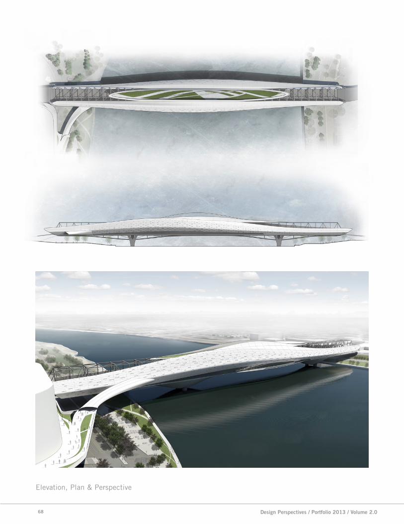
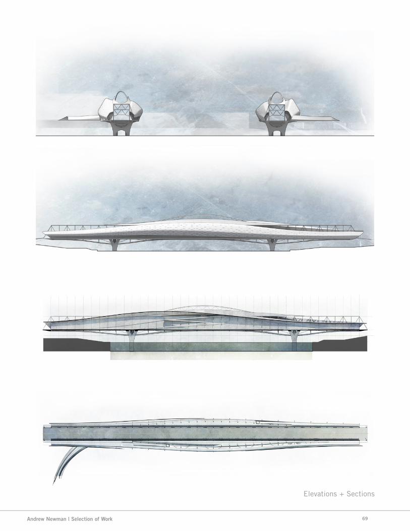
TAYLOR SOUTHGATE BRIDGE PAVILIONMASTER’S THESIS | PARAMETRIC UTILITY + FORM / Spring 2013
The scope of this thesis research and design project encompasses the virtual design process as well as the design of the product. The thesis document will focus on rationalizing the methods of execution, creating a substantial root for further constructed exploration.
The point of departure for the design project was informed by overlaying current trends in curtain wall methods and parametric design techniques. The project focus will be prioritized on the relationship between the composition of the enclosure elements and the existing constructs of an particular site condition and program.
My thesis design project objectives include an architectural proposal for a new bridge enclosure for the use
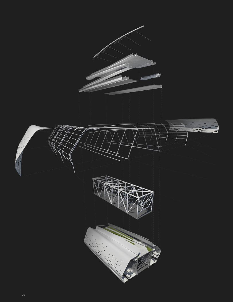
of pedestrians. This enclosure will be physically attached to existing automobile bridge that spans from the heart of downtown Cincinnati, Ohio to Newport, Kentucky. The new pedestrian bridge will include a rooftop garden, observation deck, bar and open gallery space. In order to attain realistic structural integration, some preliminary calculation will be necessary for load distribution.
This bridge enclosure system will employ the use of a curtain wall-like assembly that is parametrically generated and controlled. By integrating a context and program to the design project, a set of global, local, and environmental parameters will be present to drive the design of this architectural project.
02/01
64

Andrew Newman | Selection of Work 65

Design Perspectives / Portfolio 2013 / Volume 2.0
Existing Conditions
Site Views
66

Andrew Newman | Selection of Work
Site Zones
Proposed Circulation Site Parameters
67
Design Perspectives / Portfolio 2013 / Volume 2.0
Elevation, Plan & Perspective
68
Andrew Newman | Selection of Work
Elevations + Sections
69
Design Perspectives / Portfolio 2013 / Volume 2.070

Andrew Newman | Selection of Work 71


Design Perspectives / Portfolio 2013 / Volume 2.0
PARAMETRIC LANTERNPARAMETRIC LANTERN | GRASSHOPPER SCRIPTING / Spring 2012
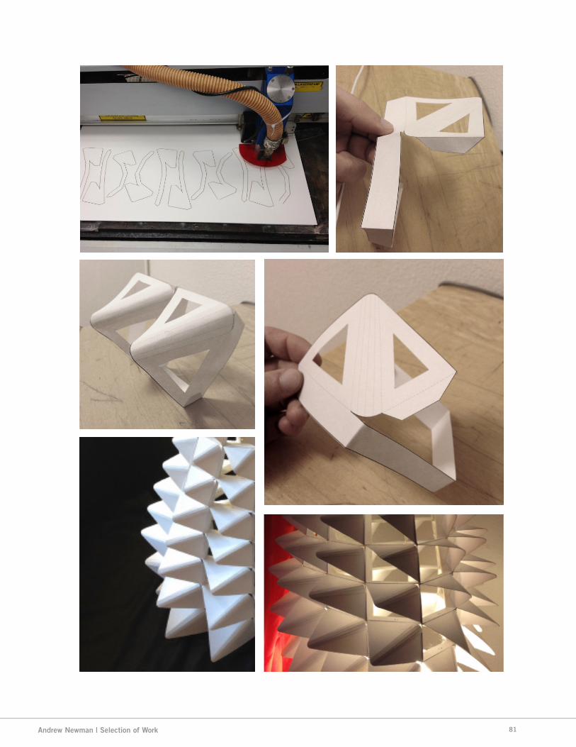
The objective of this course was to utilize scripting methods such as Grasshopper and Rhino-scripting to develop a light fixture. The next objective was to fabricate the light using lasercutters and other rapid prototyping methods.
The first part of the assignment was to develop a volumetric surface model with the goal of populating a modularized component within a systematic structure. Using scripting I was able to subdivide the lofted surface into a individual bays. Using box-morphing and scripting logic I was able to devise a way to populate the surface with a variety of geometric shapes. The next steps were to group these subdivisions in a way that I could control their behavior parametrically.
The next steps consisted of separating each row of faces. Once the rows had their own separated function, I was able to control the row’s geometry separately.
The diamond components were a series of points that were connected and faceted. The particular shape and deformation of the diamond was driven by a sin curve. From top to bottom, the diamond geometry gradually closes, but the trimmed openings get larger.
From using Grasshopper to manage every step in the process, I have not only become knowledgeable of the program but have also started to think parametrically with every project since.
02/02
76


Design Perspectives / Portfolio 2013 / Volume 2.0
Grasshopper Script
Lofted Surface / Point Cloud Surface Division Surface Framing
78

Andrew Newman | Selection of Work
Component Generation Scaled/Trimmed Geometry
79

Design Perspectives / Portfolio 2013 / Volume 2.0
Parametric LanternIllustration | Rhino + Illustrator
Opposite: Fabrication Photographs
3
1
2
80
Andrew Newman | Selection of Work 81

Design Perspectives / Portfolio 2013 / Volume 2.0
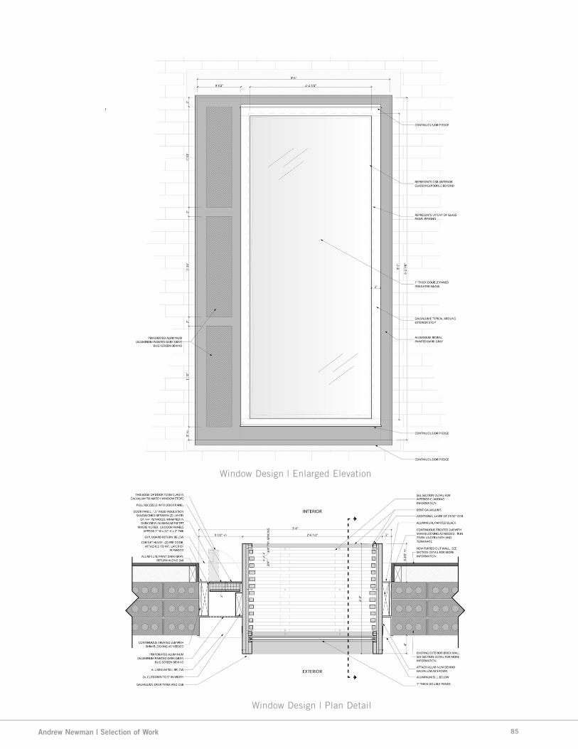
DESIGN | Build STUDIO METROLAB DESIGN BUILD STUDIO / Spring 2012
The MetroLab Design/Build studio was a class that introduced students to the concept of design-build. In the studio each student was responsible for a system of an historic building in Over the Rhine sections of downtown Cincinnati.
At the outset of the project, it was important to analyze the current conditions that the building was in, and perform tests to evaluate lighting levels, structural stability, moisture leakage, and other systematic problems.
I chose to analysis the existing non-party walls with the vision of enhancing the
current windows that were in filled with concrete masonry units.
The vision I had was inspired by the box window methods. This assembly system would allow me to give a threshold of tolerance to a non-linear condition. Through the use of blocking and vents, I designed the box window to suspend in the opening.
Cladding the inner faces of the window with strips of cedar, developed by using grasshopper and rhino, I thought it would be elegant to slowly bow the strips to mimic the existing conditions.
02/03
82

Andrew Newman | Selection of Work
MetroLab Design|Build ProjectSite | Existing Conditions
83

Design Perspectives / Portfolio 2013 / Volume 2.0
Window Design | Section Detail
84
Andrew Newman | Selection of Work
Window Design | Plan Detail
Window Design | Enlarged Elevation
85

Design Perspectives / Portfolio 2013 / Volume 2.086

Andrew Newman | Selection of Work
Top: Window Design | Exterior RenderingBottom: Window Design | Cut-away Section
87

Design Perspectives / Portfolio 2013 / Volume 2.0
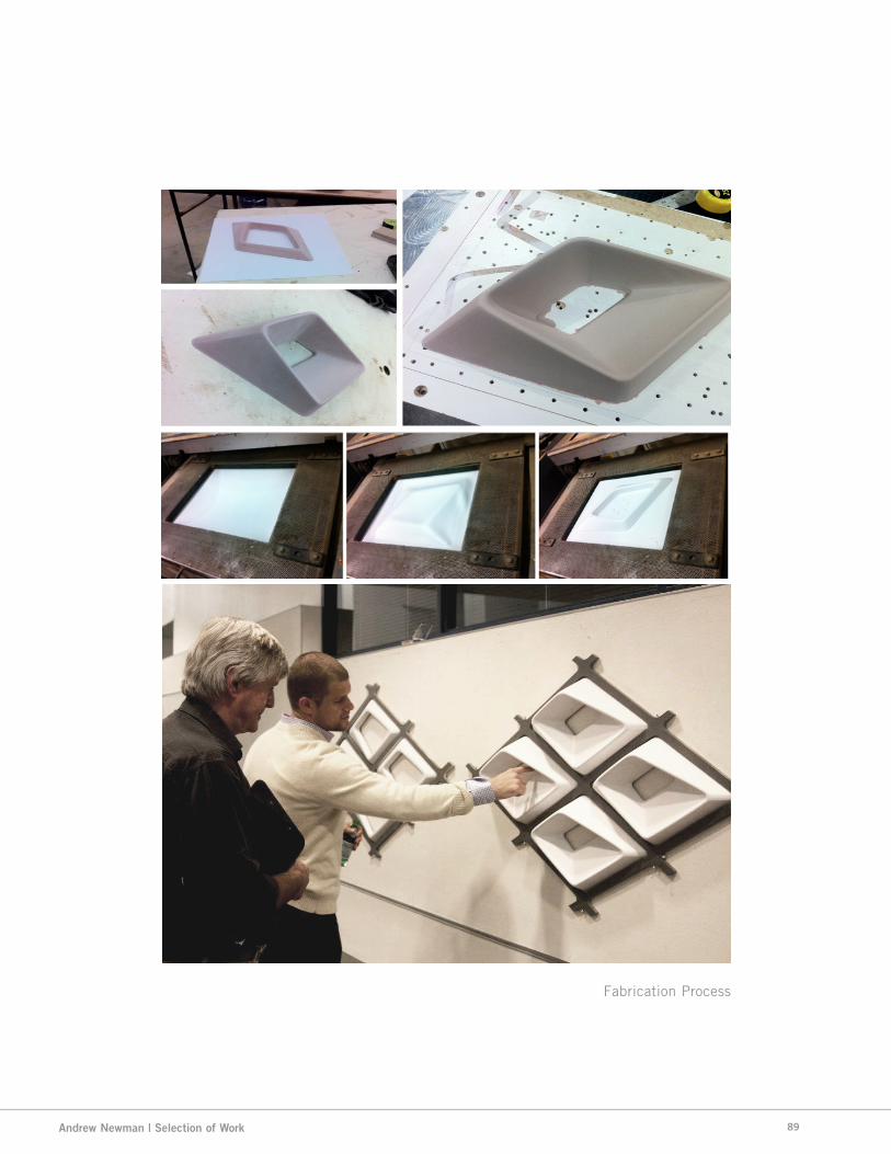
RE-SKINNING STUDIORE-SKINNING - EXISTING FACILITY / Fall 2011
In this professional and academic collaboration, topics such as parametric design, building performance analysis, simulations and fabrication were introduced with the objective to design and fabricate building facade components.
This course heavily relied on involvement of practitioners during the course. Co-taught by Ming Tang, Dr. Ajla Aksamija, Todd Snapp and Mike Hodge, the course covered parametric modeling techniques associated with performance-based design and digital fabrication.
The students were introduced to a real adaptive re-use project, where a 10-story, 400,000 SF (37,000 SM) cold storage facility constructed during the 1910’s is being converted into a commercial office building.
The independently structured exterior facade of this building will be removed and replaced. Therefore, the purpose of the collaboration was to design a new building skin for this project using digital design methods and performance analysis and to construct physical prototypes using digital fabrication methods.
Using a di-grid system, each shading component was morphed depending on the amount of radiation that was present on that particular area of the facade. Using Maya and 3D Max to construct and render the computer model, I learned one of the many ways to create specifically controlled components that could be fabricated into a prototype.
02/04
88
Andrew Newman | Selection of Work
Fabrication Process
89


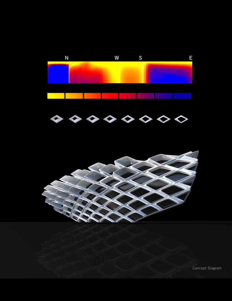
Concept Diagram
N W S E

Section Perspective


Design Perspectives / Portfolio 2013 / Volume 2.0
S.E.C STUDIOCranbrook Wellness Center / Spring 2011
This comprehensive building studio was the first studio that I took when I started the program. The class was structured around teaching us the hierarchical methods of assembly. It also established a theoretical lens the decision making process.
The program for this particular project was a wellness center on the campus of Cranbrook Acadamy in Michigan. The outlining goal of the studio was to study the mechanical, construction, and structural systems with the intent of finding integrated relationships.
The development of the constructional ethic of the building through detailed drawings of the spatial envelope assemblies was an end product of the studio.
Drawings, models and renderings were to demonstrate evolving ideas about assembly, construction, material, and space. Illustrating one’s attitudes about how integration (structure, thermal envelope, and environmental controls) deployed in space was necessary to inform decisions about envelope.
1940 - 42 1998-2000 2009 2011 - project proposal
02/05
96

Andrew Newman | Selection of Work
Site Diagram
97

Design Perspectives / Portfolio 2013 / Volume 2.0
Site Analysis
98

Andrew Newman | Selection of Work
Site Analysis
99

Design Perspectives / Portfolio 2013 / Volume 2.0
Forming The Quad
Entry Sequence Spatial Diagram
100

Andrew Newman | Selection of Work
Formal Analysis
101
Design Perspectives / Portfolio 2013 / Volume 2.0
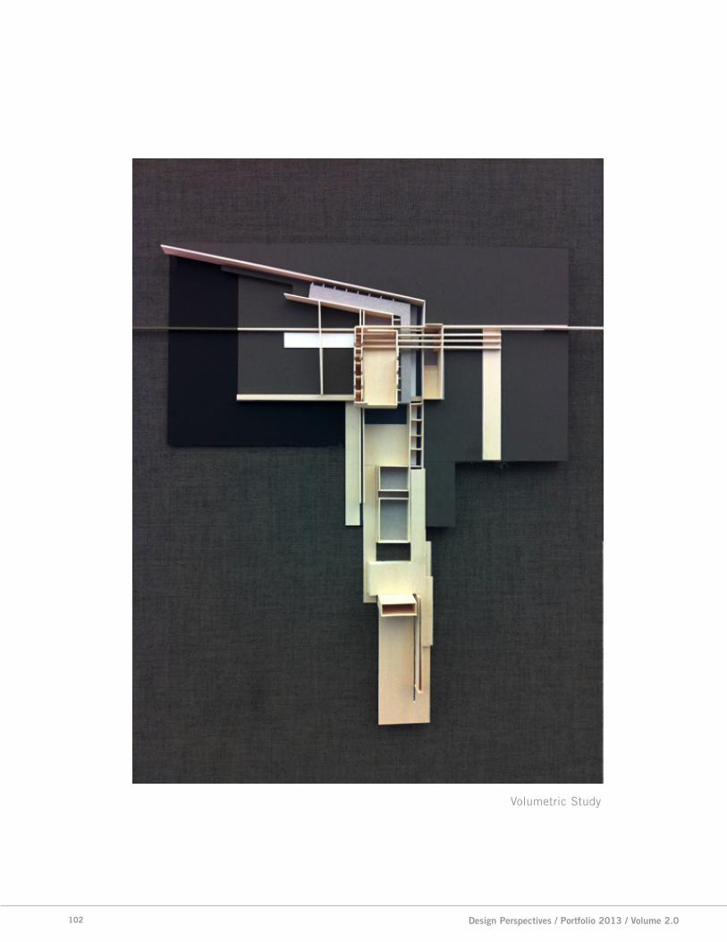
Volumetric Study
102

Andrew Newman | Selection of Work
Top: Ground LevelBottom: Basement Level
103


Design Perspectives / Portfolio 2013 / Volume 2.0
Section Detail of Hot Spa
106

Andrew Newman | Selection of Work
Exterior Envelope Rendering
107


Andrew Newman
ThankYou!