and consumer electronics - world radio history
TRANSCRIPT
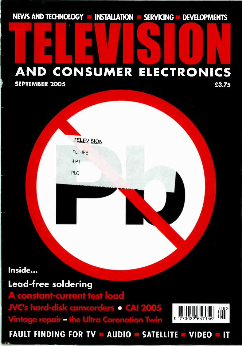
NEWS AND TECHNOLOGY INSTALLATION SERVICING DEVELOPMENTS
AND CONSU MER ELECTRONICS SEPTEMBER 2005
TELEVISION
PLJ-JPE
4P1
PLQ
Inside...
Lead-free soldering
e, constant-current test load NC's hard-disk camcorders • CAI 200 Vintage repair - the Ultra Coronation Twirl
£3.75
ULJ llt, FAULT FINDING FOR TV AUDIO SATELLITE VIDEO IT

I
TELEVISION TEST PATTERN GENERATORS P R O M A X The new GV 998 is a digital pattern generator offering
more advanced features at again a realistic price.
Those features include :
• MPEG-2 format Transport Stream generation
• Video and audio included in the TS
• Video and audio inputs • Generation of a variable frequency sound carrier for decoding verification
• Multistandard and multisystem analogue TV signal generation • Possibility to edit different fields of the TS database to present the name of the
service provider • Remote control via a personal computer • Moving video patterns to check MPEG-2 decoders
IDEAL FOR WIDE SCREEN
IDEAL FOR PLASMA DISPLAYS
PROMAX GV SERIES • Choice of 12 instruments • NICAM and Teletext
• 4:3 and 16:9 Formats • Full field and VITS • Computer Controlled • Front panel memories • Own Company Logo • Computer Monitor testers • Hand Held Models
• Multi Standard, PAL. NTSC, SECAM • High Quality Construction • Attractive Price Levels • Full After Sales Service • Available from Stock
P R O M A X
rien"."7"-----;;;.77" e
• - - • M#11#1•1111 - - °URI! M OM
1>V12 ee..1 é M r --
imp: re, rer red.
.•-•" i>9) r- ............„ o
FOR TELEVISION PATTERN GENERATORS, THERE'S NO WIDER CHOICE THAN WITH PROMAX
SELECTED ITEMS FROM THE PROMAX RANGE OF TEST EQUIPMENT
MS 250 Analogue and Digital Satellite Detector.
PRODIG 1+ Satellite Dish Installer's Meter Does more than just BSkyB
PRODIG 2 Analogue & Digital Aerial Meter
Measures digital channel pown . and C/N
MC 577 Analogue & Digital. Satellite & Terrestrial
Measures channel power and C/N
PROLINK 3 + 4 PREMIUM Satellite & Terrestrial, Analogue & Digital.
Spectrum Analyser with BER (optional on P3)
P R O M A X Alban ALBAN ELECTRONICS LIMITED
THE PROMAX SERVICE CENTRE
6 Caxton Centre, Porters W ood,
St. Albans, Hertfordshire, AL3 6XT.
TEL: 01727 832266 FAX: 01727 810546
WEB : www.albanelectronics.co.uk
EMAIL : info ealbanelectronics.co.uk
SALES + SERVICE + CALIBRATION
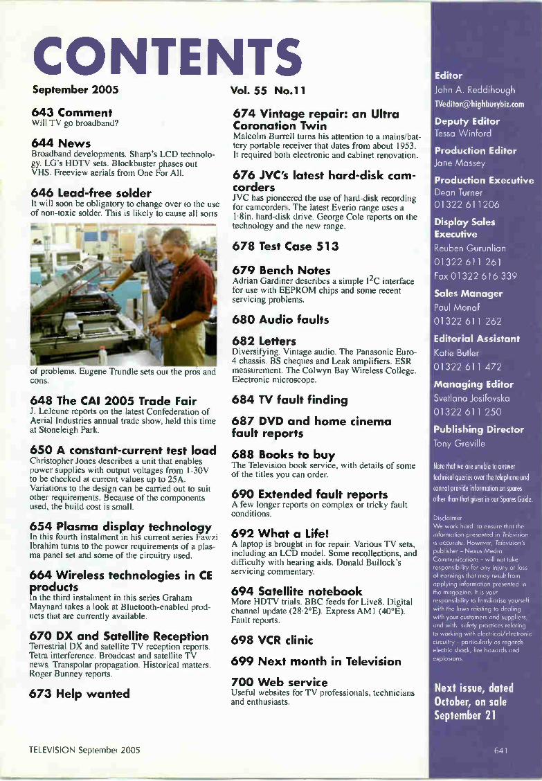
CONTENTS September 2005
643 Comment Will TV go broadband?
644 News Broadband developments. Sharp's LCD technolo-gy. LG's HDTV sets. Blockbuster phases out VHS. Fre-eview aerials from One For All.
646 Lead-free solder It will soon be obligatory to change over to the use of non-toxic solder. This is likely to cause all sorts
of problems. Eugene Trundle sets out the pros and cons.
648 The CAI 2005 Trade Fair J. LeJeune reports on the latest Confederation of Aerial Industries annual trade show, held this time at Stoneleigh Park.
650 A constant-current test load Christopher Jones describes a unit that enables power supplies with output voltages from 1-30V to be checked at current values up to 25A. Variations to the design can be carried out to suit other requirements. Because of the components used, the build cost is small.
654 Plasma display technology In this fourth instalment in his current series Fawzi Ibrahim turns to the power requirements of a plas-ma panel set and some of the circuitry used.
664 Wireless technologies in CE products In the third instalment in this series Graham Maynard takes a look at Bluetooth-enabled prod-ucts that are currently available.
670 DX and Satellite Reception Terrestrial DX and satellite TV reception reports. Tetra interference. Broadcast and satellite TV news. Transpolar propagation. Historical matters. Roger Bunney reports.
673 Help wanted
Vol. 55 No.11
674 Vintage repair: an Ultra Coronation Twin Malcolm Burrell turns his attention to a mains/bat-tery portable receiver that dates from about 1953. It required both electronic and cabinet renovation.
676 JVC's latest hard-disk cam-corders J VC has pioneered the use of hard-disk recording for camcorders. The latest Everio range uses a 1.8in. hard-disk drive. George Cole reports on the technology and the new range.
678 Test Case 513
679 Bench Notes Adrian Gardiner describes a simple I2C interface for use with EEPROM chips and some recent servicing problems.
680 Audio faults
682 Letters Diversifying. Vintage audio. The Panasonic Euro-4 chassis. BS cheques and Leak amplifiers. ESR measurement. The Colwyn Bay Wireless College. Electronic microscope.
684 TV fault finding
687 DVD and home cinema fault reports
688 Books to buy [he Television book service, with details of some of the titles you can order.
690 Extended fault reports A few longer reports on complex or tricky fault conditions.
692 What a Life! A laptop is brought in for repair. Various TV sets, including an LCD model. Some recollections, and difficulty with hearing aids. Donald Bullock's servicing commentary.
694 Satellite notebook More HDTV trials. BBC feeds for Live8. Digital channel update (28.2°E). Express AMI (40°E). Fault reports.
698 VCR clinic
699 Next month in Television
700 Web service Useful websites for TV professionals, technicians and enthusiasts.
Editor
John A. Reddihough
Deputy Editor
Tessa Winford
Production Editor
Jane Massey
Production Executive
Dean Turner
01322 611206
Display Sales
Executive
Reuben Gurunlian
01322 611 261
Fax 01322 616 339
Sales Manager
Paul Monaf
01322 611 262
Editorial Assistant
Katie Butler
01322 611 472
Managing Editor
Svetlana Josifovska
01322 611 250
Publishing Director
Tony Greville
Note that we are unable to answer technical queries over the telephone and cannot provide information on spores other than that given in our Spares Guide.
Disclaimer We work hard to ensure that the information presented in Television is accurate. However, Television's publisher - Nexus Media Communications - will not take responsibility for any in¡ury or loss of earnings that may result from applying information presented in the magazine. It is your responsibility to familiarise yourself with the laws relating to dealing with your customers and suppliers, and with safety practices relating to working with electrical/electronic circuitry - particularly as regards electric shock, fire hazards and explosions.
Next issue, dated October, on sale September 21
TELEVISION September 2005 I

/1/<<s 47.c) 1/, ,e le 0 4, 0 <<14/ 4)?• -c/ C
The good news is,
we can replace it..!
How some people manage to lose or break their remote controls is sometimes quite unbelievable. However, lose them and break them they do. That's why the Classic range of replacement remote controls
covers just about every make and model of television, satellite, video and Freeview system available in the UK. Whilst we may not be qualified to remove a Sony control stuck in the digestive tract, with over 20 years industry experience, we will certainly be able to
replace it.
High quality, reliable and user friendly with all the functions of the original, available now through our nationwide network of distributors.
For up to date cross-reference information or for more information on the whole Classic range of service products, visit our website ‘vww.classic-serviceparts.com, phone
us on 01635 278678 or email us at uksales classic-serviceparts.com.
[classic, Technical helpline 01635 278678

COMMENT COPYRIGHT © Nexus Media Communications 2005. All rights reserved. No part of this publication
may be reproduced, stored or transmitted I n any form or by any means without the writ-
ten permission of the publishers.
All reasonable precautions are taken by
Television to ensure that the advice anc data published are reliable. We cannot however guarantee it and we cannot accept legal responsibility for it.
CORRESPONDENCE All correspondence regarding advertisements
should be addressed to the Advertisement Manager, Television, Nexus Media
Communications, Media House, Azalea Drive, Swanley, Kent, BR8 81-1U. Editorial cor-respondence should be addressed to
Television, Editorial Department, Nexus
Media Communications, Media House,
Azalea Drive, Swanley, Kent, BR8 8HU.
INDEXES AND BINDERS Indexes for Vols. 38 to 54 are available at £.50 each from SoftCopy Ltd., who can also supply an fifteen-year consolidated index on comput-
er disc. For further details see page 699. Binders that hold twelve issues of Television are
available for £6.50 each from Modern Bookbinders, Pringle Street, Blackburn, BB1 1SA
Telephone: 01254 59 371. Make cheques payable to "Television Binders".
Newstrade Enquires by Seymour Distribution Ltd.,
86 Newman St, London, W1T 3EX.
ISSN 0032-647X
Newstrade Hotline If you are experiencing problems gen ng
copies through your newsagent, please call
Debbie Jenner on 01322 611210.
SUBSCRIPTIONS Customer Interface Ltd.,
Cary Court,
Some rton,
TA11 7BR.
Telephone 0870 4287950
Fax 01458 271146
Subscription rates: UK 1 year £39.00 2 years £70.00 3 years £90.00
Mainland Europe 1 year £57.00 2 years £100.00 3 years £135.00
Rest of World 1 year £74.00 2 years £130.00 3 years £175.00
Cheques should be made payable to Television
BACK NUMBERS If available issues are £4.50 each.
NEXUS MEDIA CO M MUNICATIONS
Will TV go broadband?
The question should perhaps be whether broadcasting will go broadband, since radio and other services can as well be
distributed via the internet as TV. In fact internet radio is growing quite rapidly world-wide. The ultimate question however is whether radio and TV via the internet will eventually supersede other forms of distribu-tion? It's at present impossible to answer the question. We just don't know what people will eventually find most convenient, and whether one mode of distribution will have such overwhelming advantages over the oth-ers that they simply fade away. Right now we are at the start of a period of experiment and change, with four basic modes of distri-bution — in practice they overlap to some extent. These are terrestrial off-air, satellite, cable, and internet via a broadband line. It's assumed of course that everything will be digital within a few years. The advantage of the terrestrial off-air
approach is that it's relatively cheap and cheerful for the user. The striking success of Freeview bears this out. Figures in Ofcom's recent report on digital radio, TV and com-munications in the UK show that more than 3-3m Freeview set-top boxes and integrated digital TV sets were sold during 2004. This brought the total up to 4-5m by the end of the year. Still less than BSkyB at 7-7m, but growing at a much faster rate. Freeview appeals because, for one thing, it is just that — free. And people are used to getting their TV free or, rather, for the cost of the licence fee. DIT has its limitations, for example the amount of interactivity possible, but who cares all that much about such add-ons pro-vided you get a decent basic service? The other question with DTT is whether building all those transmitters to try to reach every-one is worthwhile when it can be more easi-ly achieved via satellite. But for most of us DTI' will probably continue to be the sim-plest solution for the time being — though the broadband alternative is looming up, and raising all sorts of questions. Digital cable seems to have become
somewhat marginalised. Being cable-based, it overlaps with internet distribution — the differences lie in the digital encoding and network arrangements. Cable TV provides a convenient way of getting all your needs via one provider — broadcasting and telecommu-nications, including the internet. Will the cable companies eventually go the whole way and simply adopt internet technology? At present the existing system is better for quality and reliability, but these advantages might not continue as internet technology advances. NTL has been conducting trials of HDTV via digital subscriber lines since March.
Satellite TV appears to have stalled, though BSkyB seems to be confident that it can reach its aim of 10m subscribers by 2010. The technology is tried and tested, and the company is expert at providing the pro-grammes people want — and getting them to pay for the service. The great advantage from a distribution point of view is that the signals are easy to pick up almost anywhere within the service area. Which brings us to broadband TV. As
noted in our news pages, all broadcasters seem to be keen on trying out his new mode of distribution. It involves costs for the view-er, but for most people subscribing to an internet provider will be an unavoidable cost anyway, part of the modern data-based way of life. There has been quite a lot of hype about broadband TV, but not all forecasters agree. One recent report suggested that by 2010 six per cent of viewers in the UK and Germany will be using broadband TV. That's not a particularly significant number. It will probably depend on how good the technolo-gy becomes. At present it's easier for most viewers to connect their TV equipment up in one of the standard ways. But it's interesting that BT will from next year be selling a dual broadband/Freeview box. This could offer the best of both worlds — especially with the bonus of a built-in PVR. Eventually most people might adopt
broadband TV because of its versatility and the extraordinarily wide offerings it can pro-vide. A recent report in the New Zealand trade magazine SatFACTS (June, 2005) says that Telecom NZ's Jerstream service, appar-ently one of the most advanced in the world, can among other things provide sixty live US channels and 66 live Russian channels at the click of a mouse. The report mentions more than 700 "public video streaming" sites, with several hundred more coming online each month. Radio too of course. The Ofcom report says that 19 per cent of adults with a web connection in the UK listen to radio online. Broadband communication brings with it
all sorts of possibilities. The NZ report men-tions "radio bloggers" who can run a private radio station with worldwide distribution. No reason why we can't have TV blog stations too — there's already much video streaming. But there doesn't seem to be much profit in basic broadband provision at present. The Ofcom report noted that, because of acceler-ating price cuts, revenues grew by only 6-8 per cent last year despite the number of con-nections doubling. What we don't know at present is the full
potential of broadband technology. It is this that will determine how far broadcasting goes down the broadband trail.
TELEVISION September 2005 643

NEWS
Broadband developments Ofcom reports that there are now more households with a broad-band than a dial-up internet con-nection. 2005 is the year during which broadband has become a genuinely mainstream consumer product, says Ofcom. It's now present in almost thirty per cent of UK households and business-es and is being actively consid-ered by many more. By the end of June there were over eight million connections, and by the end of the year 99.6 per cent of UK homes will be connected to a broadband-enabled exchange. With the growth of broad-
band, more and more broadcast-
ers and network providers are planning to offer IPTV (Internet Protocol TV) services via broad-band links. The BBC put the first episode of the new comedy series The Mighty Bosh online before its terrestrial transmission, and plans to put more first-show programmes online. The BBC is also running a major trial of its interactive media player (iMP) this September. Some 5,000 households will be involved in the three-month trial. They will have a choice of 190 hours of TV and 310 hours of radio pro-grammes. Channel 4 is understood to be
planning to put its programmes online by the end of the year, and BSkyB has announced plans for a broadband TV service by the end of 2005. Under the scheme, subscribers to the top-tier pack-ages Sky Sports World, Sky Movies World and Sky World will be able to access broadband services. Sky Sports World view-ers will be able to receive sports highlights, news and interviews; Sky Movies World subscribers will be given a choice of about 300 old and new films; and Sky World subscribers will be able to receive both packages. Telewest has on trial a beta
broadband service known as Blueyonder TV. Subscribers can access a number of programmes including sport, movies and community material. BT, which plans to start an
IPTV service next year, has announced that it will make available at £0 a set-top box with an 80GB hard drive for programme storage. It will be able to receive both Freeview and INN services and have a fourteen-day forward and seven-day backward electronic programme guide. A full-scale trial of the service will start next March.
Sharp's LCD technology Two new LCD developments have been announced by Sharp. The first is a dual-vision LCD that enables two people to see different pictures simultaneous-ly. It uses a 'parallax barrier' that acts as an optical filter, effectively splitting the screen into two. The accompanying photo shows the effect, while Fig. 1 illustrates the principle. One viewer could be watching a TV programme while the other one could be editing a video or accessing the internet. The barri-er can be switched off for nor-mal viewing. Sharp has demon-strated a 26in. prototype moni-tor and intends to start volume production immediately. The second development is
an LCD screen that can be switched between narrow- and wide-angle viewing. It works by
covering a normal TFT LCD screen with a special liquid-crystal switching material that focuses the backlight so that, when brought into operation, it focuses the backlight to shine in front of the display and not at the sides. Fig. 2 illustrates the principle. The result is that only those positioned directly in front of the display get a clear image. Sharp plans to start mass-pro-duction of such screens this year, pointing out that that they will provide greater privacy for laptop PC users in public places. Sharp has launched its 65in.
LCD IV set (see CEATEC report, December) in Japan at a price equivalent to about £8,000. Model LC-65GE1 incorporates Sharp's QS (Quick Shoot) technology, which improves the response with
Sharp's dual-vision LCD screen.
Fig. 1: Sharp's dual-vision LCD system.
O User C
L CD
A
• 41 0 User B
User A All users see view [Al
User C cannot see \nerd AI
LCD
User C User
User f3 cennot see view( A)
User A
User A sees view I Al
Fig. 2: Sharp's narrow-/wide-angle LCD switching system.
moving objects, and a new four-wavelength backlight that adds crimson to blue, green and red to give faithful reproduction of pure red colours. Power con-sumption is quoted as 619W, which is less than that of simi-lar-sized plasma models. Sharp has launched the P50
range of LCD TV sets in the UK. The displays have a 960 x 540 resolution, which corre-sponds with standard PAL scan-ning. Previously, LCD sets have had either 640 x 480 (VGA) or
1,366 x 768 (WXGA) resolu-tion, which are standards intend-ed for PC use. With these, either some lines have to be dropped or extra lines have to be created by interpolation. Both processes can add noise to the video infor-mation. The panels used in P50 series sets incorporate Sharp's Advanced Super View technol-ogy, which enhances the bright-ness and contrast ratio. A sim-ple down-conversion is provid-ed to give good results with HDTV signals.
September 2005 TELEVISION

NEWS
LG's HDTV sets LG Electronics has announced that it will launch the world's first plasma HDTV sets with an integrated HD digital video recorder in the UK early next year, following launch of the sets in Korea and North America last May. Available with 50 or 60m. screens, the PY2DR series has a 160GB hard drive that can store up to thirteen hours of HD program-ming or 63 hours of standard-
definition programming. The new widescreen plasma-DVRs incorporate an automatic time-shift feature that records contin-uously in one-hour intervals. Other features include slow-motion rewind and forward capabilities, instant replay and an EPG. The US versions have an
ATSC tuner for HD DTI' and unscrambled digital cable TV plus analogue broadcast and
cable tuners. They also have an integrated 9-in-2 multi-memory card reader (Compact Flash, SmartMedia, MultiMediaCard, SD Memory Card, xD and sev-eral other Memory Stick ver-sions), enabling still images to be viewed and digital music such as MP3 files to be listened to. Users can store digital pho-tos or music from a digital cam-era or MP3 player on the hard drive via a memory card. The
recorder is able to create a music-photo album, so that stored photos can be accompa-nied with music in a slide show. The sets have an HDMI input with HDCP; IEEE 1394 with DTV Link; and PIP (picture-in-picture), POP (picture-outside picture) and split-screen options. The 50in. version has a
60,000-hour DoubleLife panel with a contrast ratio of 5,000:1 and a brightness of 1,000cd/m2.
Blockbuster phases out VHS Blockbuster, the leading video rental chain with some 720 outlets in the UK, has announced that it will cease stocking VHS films over the next few months. The move has come as DVD has taken over as the medi-um for movie distribution. Industry figures show that last year 111 million films on OVO were sold, compared with only 13 million in VHS form. Other retailers, includ-ing HMV and Dixons, are dropping VHS.
HD-DVD adopts AACS The OVO Forum has announced that the new HO-OVO blue-laser discs will use the Advanced Access Content System developed by Intel, IBM, Microsoft, Panasonic, Sony, Toshiba, Disney and Warne to provide copyright protec-tion. Players will store the decryption keys in flash memory.
Freeview aerials from One For All One For All has intro-duced a range of two aeri-als for Freeview reception. Model SV9320 is a stylish indoor aerial that provides 20dB amplification and comes with a one metre coaxial lead for flexible positioning. Price is about £25. It has non-scratch, non-slip feet and can be
set up horizontally or ver-tically. The outdoor Model SV9350 incorporates a Freeview receiver and 15dB amplifier, also inter-ference filters, and comes with a 6m coaxial cable and mounting equipment. For further information check at www.oneforall-int.com
Ofcom news Ofcom reports that over sixty per cent of UK households can now receive digital TV, with the number increasing by more than 250,000 a month. Seventy per cent of the growth last year was
attributed to Freeview — by the end of the year some 4-6m households (almost twenty per cent) could receive Freeview transmissions. Ofcom has increased the
number of channels that are
Cabinet recycling Sharp has developed technology to recycle the non-halogen resins used in its Aquos LCD TV set cabinets. The new technology enables the plastic material that makes up the cabinet to be easi-ly recycled. Sharp plans to
establish technologies to recycle LCD TVs in anticipation of the EU WEEE directive. By the end of its 2006 trading year the com-pany aims to have developed a new LCD TV cabinet material with high recyclability based on
required to provide subti-tling, signing and audio description by 2006. A total of 76 channels will have to provide these TV access service compared with 70 at present.
the new technology. Sharp has published "Guidelines for LCD Panel Recycling" which the company will be distributing to promote designs that allow ready processing of redundant LCD TV sets.
Silicon laser Intel has announced the development of a silicon-based laser, which could lead to a dramatic reduction in the cost of lasers. The research team at Intel's Santa Clara, California headquarters produced the first CVV silicon laser last Christmas Eve. One major problem that had to be overcome was "two-photon absorption", which caused blockages as free electrons absorbed the light passing through the silicon. The first use, in possibly three-five years time, is expected to be in optical modulators. Other applications could be to provide short-distance optical interconnections in computers and for medical purposes.
TELEVISION September 2005

Soldering has been in use since before there was any such thing as
an electrical or electronics industry. The basic materi-al is tin (Sn), an expensive and innocuous material that melts at 230°C. For practical purposes it is combined with other mate-rials to improve its proper-ties — silver, copper, lead and others. These deter-mine the characteristics of the solder — the melting temperature, physical strength, wetting' and wicking'. The solder we have used over the years, with great success, has typ-ically consisted of 63 per cent tin and 37 per cent lead, sometimes with a small admixture of copper.
The environmental aspects There has been growing concern about the effects of lead (Pb) for many years, because it's a toxic metal that can attack the central nervous system. Manufacturers have been adopting alter-native solders that don't contain lead and, from 1 July 2006, its use in manufacturing and reworking — that's where we come in — will, under the European RoHS (Restriction of Hazardous Substances) Directive, be illegal. The manufacture, use and repair of products that contain lead
do not present any real health problems. The risk arises when the equipment has been scrapped and discarded, as the lead can enter the atmosphere from an incinerator or leach into ground water from a landfill site. Lead has already been eliminated from paint, plumbing and petrol, no doubt with some benefit to the environment, but in certain quarters its mandatory removal from solder is seen as misguided and even harmful, creating more problems than it solves. It has been suggested that the risk of seepage from landfill is minimal; that alternative solder alloys are also toxic; that the higher process temperatures required with lead-free solder are wasteful of energy and contribute to global
Surface-mounted IC pin joints mode with SAC lead-free solder.
It will soon be obligatory to change over to the use of non-toxic solder. This is likely to cause all sorts of problems. Eugene Trundle sets out the pros and cons
warming and atmospheric pollution; while at the same time production costs are increased. It's certainly true that
the lead in solder accounts for less than one per cent of that mined and used. Eighty per cent of the lead goes into lead-acid storage batteries for use in road vehicles and energy-stor-age systems. Substitutes for these are hard to find, and I've seen no sugges-tions of any plans to out-law them, though there are very strict rules regarding their disposal at their end of life. Of that one percent of lead used in solder, if one joint in a hundred thousand needs to be repaired its contribution to the world consumption of
lead is less than half of one ten-millionth of what's at large out there. But even so we have to change over to lead-free solder by next summer, or we will be committing a criminal offence.
Traditional solder Conventional solder that contains lead is relatively cheap but works very well. It melts very rapidly at about 183°C, is quick to wet the copper and tin surfaces with which it works, and read-ily forms a good bond between them. It flows well and wicks' very well — the latter is its capillary action, for example up and across copper wire and surfaces. Used with a good flux, either as a core in the solder or applied separately, it is easy to use and gives good and reliable results.
Lead-free solder In comparison lead-free solder has several drawbacks. Because of its higher melting temperature (about 34°C higher), its use in factory assembly work has necessitated the reconfiguration of wave-flow soldering equipment and the redesign of some com-ponents that are vulnerable to physical cracking, such as multi-
64 6 September 2005 TELEVISION

layer ceramic capacitors. Plastics are more likely to melt or deform, while the slower wetting properties of lead-free solder and its high surface tension require care to avoid tombstoning', when small surface-mounted compo-nents such as resistors and capacitors jump upright as one end reaches the melt-ing point before the other — most of those who have worked with surface-mounted components will be familiar with this. Other production problems are board and component warping and the risk of cracking in through-board plated holes. These are caused by the higher tern-perature used. Another potential problem, the for-mation of tin whiskers or 'dendrites', is caused by the combina-tion of high-tin alloys and some flux materials: the whiskers can result in short-circuiting between adjacent conductors.
A joint being made with SAC lead-free solder.
Quality-control inspection of lead-free soldered PCBs. Note the rework equipment at the left.
A substitute There is no 'drop-in' lead-free substitute for traditional solder: many alloys have been tried and tested, but all lead-free types involve compromises. Probably the best one at present for use in consumer electronics equipment, generally called Sn96•5/Ag3/Cu0-5, SAC or 7SC alloy, consists of 915.5 per cent tin, 3 per cent silver and 0.5 per cent copper. It melts at about 218°C, remains pasty over a relatively wide temperature range and cools slowly in comparison with tin/lead, making its joints more vulnerable to tension or movement for several seconds after the heat has been removed. Lead-free solder is more diffi-cult to work with because it's less ready to wet board lands and component legs. And because it has high surface tension it's more likely to create a dome-shaped joint than a conical one. Once the joint has been made and has cooled the appearance
is coarser, duller and more granular than with leaded solder — its colour is more grey than silver. Judged by the old standards, these characteristics can give the impression of a bad joint. In fact, provided it has been made properly the joint is harder, stronger and more resistant to corrosion and abrasion than a leaded-solder one, and is better at withstanding thermal and mechanical stress. While these properties are important in some
industries, none of them are very relevant to sol-dered joints in consumer electronics equipment — except, maybe, where hot-and-heavy components such as transformers, and stressy' ones like field output ICs, capacitors in line-scan circuits and plug/socket connections to a deflection yoke, are con-cerned. And most of these are disappearing as flat display devices take over from CRTs.
On the bench The workshop changeover can be carried out at any time, because lead-free solder can be used safely on old PCBs and assem-blies that were made with lead-based solder. It's
available in the form of wire, with flux core if required, down to a diameter of 0-3mm/30 SWG for very fine work, and also as a paste for use with surface-mounted assemblies. It costs three times as much as conventional tin/lead solder, but even so it remains a very small percentage of the cost of a repair job. The higher melting point calls for a higher temperature at the
tip of the soldering iron: 370°C is about right. Soldering stations with temperature control can easily be set to this. Simpler, ther-mostatic irons may be adjustable to 370°C by replacing the tip. An iron with high thermal capacity is best for lead-free work
— it's equivalent to fast acceleration as opposed to high-speed capability in a car. This equates to high wattage and an ability to transfer heat quickly to the solder and joint. In fact it could be a good time to replace an old or inadequate iron! All soldering-iron manufacturers have suitable instruments for sale, as a look in the current CPC (for example) catalogue shows. The higher temperatures associated with lead-free solder
mean that more particles and gases are generated, for example aldehydes and isocyanates. Regular or prolonged exposure to these can lead to various symptoms and, in extreme cases, occu-pational asthma. You may, especially if you do a lot of soldering work, wish to implement or upgrade fume-filter and extraction systems. Again, many suitable products are listed in the CPC catalogue.
A wave-soldering station that uses lead-free solder.
TELEVISION September 2005

iIC ON GLOBAL :TRONICS Ltd
* eel 14../Adwons Are1 •
1Ctil Regulation by Qualification
The CAI 2005 Trade Fair
J. LeJeune reports on the latest Confederation of Aerial Industries annual trade show, held this time at Stoneleigh Park
The CAI Trade Fair is now a two-day event. It appears to have been a great success this year, with a large number of visitors present. The venue at Stoneleigh Park, the National
Agricultural Centre, was ideal, with good parking and excellent facilities. There is always a certain déjà vu feel with an event such as
this, as many of the products may have been seen at road-shows earlier in the year or be tried and trusted ones being given anoth-er airing. There were nevertheless plenty of innovative products on display, designed to give better performance than their prede-cessors or enable the installer to achieve good results at less cost and with greater ease. They were of high quality, soundly engi-neered and some able to provide a real helping hand.
Cable identifier An example is the Digitach cable identifier, a test instrument that enables up to twenty cables to be identified at one time. It also shows up short-circuits. The device is simple but cleverly thought out. Outgoing cables at the head-end are connected to a sender unit, with each output socket identified by a number. At the far end of the cable a portable receiver box is connected to the cable's screen, with a probe to touch the inner conductor. A sounder indicates that connection has been made and the dis-play lights up with a number, identifying the cable. A label can then be attached to it to help with future servicing, avoiding the time-consuming business of cable tracing.
Software CD Fracarro Industries, an established supplier to the signal-distribu-tion trade, has produced a CD of software for planning audio and video reception and distribution systems. The software is user-friendly, flexible and the image quality is excellent with the
use of vector graphics. The company was also showing its new AMP series of line amplifiers, Models AMP9762 and AMP9763. Both incorporate a 5-30MHz return path, and the AMP9763 adds satellite IF (950-2,400MHz). The ±2dB flatness means however that they are not really intended for cascaded use.
Multi-satellite dish Force showed an ingenious multisatellite dish that can receive signals from satellites up to 46° apart by using a convex reflec-tor on a 55 or 90cm offset dish. The company also showed its Promaster receivers for CATV headend use. These are single-channel satellite or terrestrial types in 19in. rack-mounting cases.
New products Global Communications fielded a raft of new products including new styles of wallplates, a modular multiswitch range, home distribution equipment using CAT5e and some additions to the Professional range, including a VSAT 10MHz source and redundancy amplifier. Labgear made a strong showing. The company's June 2005
catalogue, in A5 format, provides handy information on signal-level conversion, DIT transmitters, analogue transmitters, UHF aerial groups and much more. A comprehensive range of distri-bution equipment, from wallplates to amplifiers plus acces-sories for earth bonding, Tetra filters and IR remote-control extenders, occupies the majority of the catalogue's 22 pages. A new name in the distribution field, Masterplug TradePro,
made its debut. The company is well-known for its range of mains cable reels and power-surge protection equipment. It has now launched a range of equipment including mast-head ampli-fiers, cable, distribution units, outlet plates and multiswitches. An interesting leaflet on the Johansson Profiler range of distri-
648 September 2005 TELEVISION
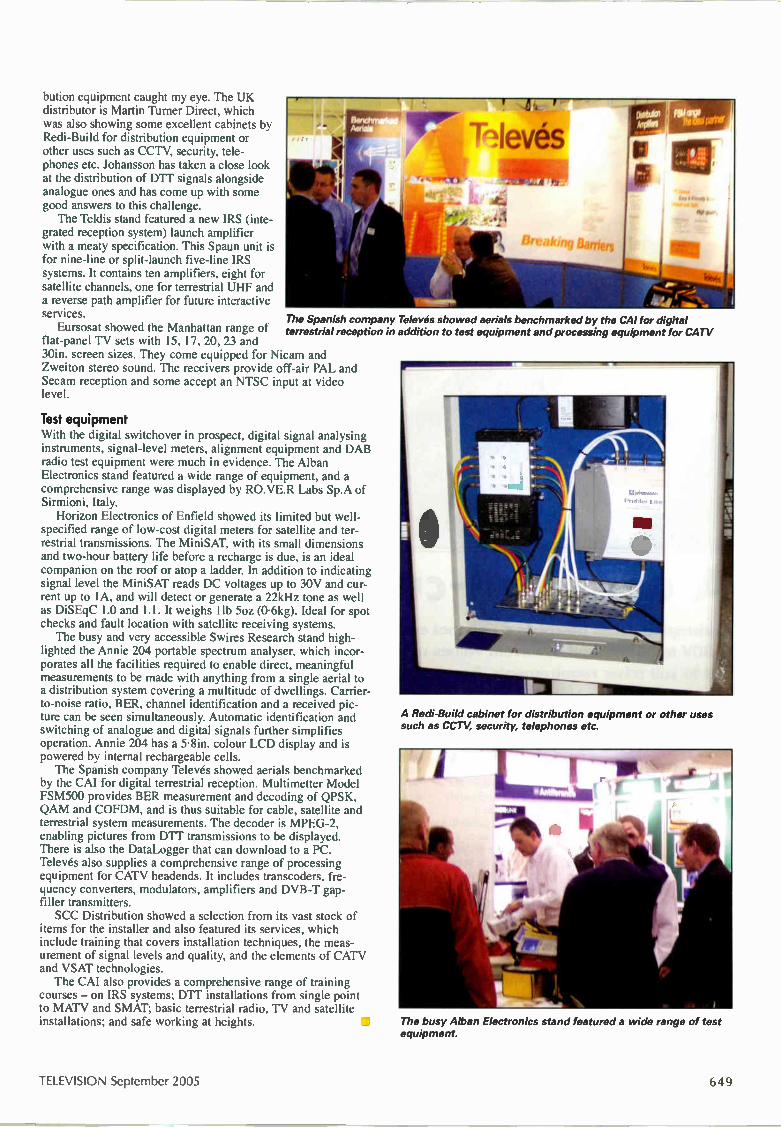
bution equipment caught my eye. The UK distributor is Martin Turner Direct, which was also showing some excellent cabinets by Redi-Build for distribution equipment or other uses such as CCTV, security, tele-phones etc. Johansson has taken a close look at the distribution of D U signals alongside analogue ones and has come up with some good answers to this challenge. The Teldis stand featured a new IRS (inte-
grated reception system) launch amplifier with a meaty specification. This Spaun unit is for nine-line or split-launch five-line IRS systems. It contains ten amplifiers, eight for satellite channels, one for terrestrial UHF and a reverse path amplifier for future interactive
Services. The Spanish company Televés showed aerials benchmarked by the CAI for digital Eursosat showed the Manhattan range of terrestrial reception in addition to test equipment and processing equipment for CATV
flat-panel TV sets with 15, 17, 20, 23 and 30in. screen sizes. They come equipped for Nicam and Zweiton stereo sound. The receivers provide off-air PAL and Secam reception and some accept an NTSC input at video level.
Test equipment With the digital switchover in prospect, digital signal analysing instruments, signal-level meters, alignment equipment and DAB radio test equipment were much in evidence. The Alban Electronics stand featured a wide range of equipment, and a comprehensive range was displayed by RO.VE.R Labs Sp.A of Sirmioni, Italy. Horizon Electronics of Enfield showed its limited but well-
specified range of low-cost digital meters for satellite and ter-restrial transmissions. The MiniSAT, with its small dimensions and two-hour battery life before a recharge is due, is an ideal companion on the roof or atop a ladder. In addition to indicating signal level the MiniSAT reads DC voltages up to 30V and cur-rent up to 1A, and will detect or generate a 22kHz tone as well as DiSEqC 1.0 and 1.1. It weighs llb 5oz (0.6kg). Ideal for spot checks and fault location with satellite receiving systems. The busy and very accessible Swires Research stand high-
lighted the Annie 204 portable spectrum analyser, which incor-porates all the facilities required to enable direct, meaningful measurements to be made with anything from a single aerial to a distribution system covering a multitude of dwellings. Carrier-to-noise ratio, BER, channel identification and a received pic-ture can be seen simultaneously. Automatic identification and switching of analogue and digital signals further simplifies operation. Annie 204 has a 5.8in. colour LCD display and is powered by internal rechargeable cells. The Spanish company Televés showed aerials benchmarked
by the CAI for digital terrestrial reception. Multimetter Model FSM500 provides BER measurement and decoding of QPSK, QAM and COFDM, and is thus suitable for cable, satellite and terrestrial system measurements. The decoder is MPEG-2, enabling pictures from DTT transmissions to be displayed. There is also the DataLogger that can download to a PC. Televés also supplies a comprehensive range of processing equipment for CATV headends. It includes transcoders, fre-quency converters, modulators, amplifiers and DVB-T gap-filler transmitters. SCC Distribution showed a selection from its vast stock of
items for the installer and also featured its services, which include training that covers installation techniques, the meas-urement of signal levels and quality, and the elements of CATV and VSAT technologies. The CAI also provides a comprehensive range of training
courses — on IRS systems; DIT installations from single point to MATV and SMAT; basic terrestrial radio, TV and satellite installations; and safe working at heights.
A Redi-Build cabinet for distribution equipment or other uses such as CCTV, security, telephones etc.
The busy Alban Electronics stand featured a wide range of test equipment.
TELEVISION September 2005 h '

A constant-current test load Christopher Jones describes a unit that enables power supplies with output voltages from 1-30V to be checked at current values up to 25A. Variations to the design can be carried out to suit other requirements. Because of the components used, the build cost is small
Photo 1: Internal view of the prototype.
W lic never a power supply needs to be tested or repaired there's the prob-
lem of providing some sort of load across the output to ensure that it will deliver its rated output current. If a bank or banks of resistors are used it's difficult if not impossible to find the right value, and a smooth change in load is difficult to achieve because of the need to use a high-power variable resistor or rheostat, which would be very expensive. It's often necessary to be able to test a supply that pro-vides 5V or less at a current of tens of amps. So the resistors used would need to be of low value with high current and power ratings. For example to test a 5V, 20A power supply a variable resistance with a value of 0.25Q at a power rating of 100W would be required! The unit described here enables
power supplies with output volt-
ages from 1-30V to be checked at current values up to 25A and pow-ers up to 100W. The specification will vary depending on the compo-nents used. The cost of construction can be kept low by using inexpen-sive and possibly second-hand components. An outline of the design considerations is provided to enable variations to be worked out to suit particular needs. The specification for the proto-
type unit was:
Load current adjustable from less than 100mA to up to 20A.
Voltage range from less than 1V to 30V.
Total continuous power capacity at least 100W (this can be exceeded but must be monitored).
Continuous operation at an air tem-
perature of 25°C.
Constant current at all voltages within the range.
The circuit of the prototype unit is shown in Fig. 1. MOSFETs Q1 and Q2, connected in parallel, pro-vide the load across the + and — ter-minals. A sensing resistor R1 is connected in series with them. This works with the operational amplifi-er UlA to control the MOSFETs. Cheap n-channel MOSFETs were chosen as the current-control ele-ments.
Design considerations and options The specification of the unit you decide to build will be determined mainly by the current-control device(s), for example IRL2203 or IRF540; the value and power rating of the sensing resistor; the opera-
650 September 2005 TELEVISION

+12V0
OV
= C4 100
R6 1k
0.8V
> R5 2k2
D1
0.25V
R2
RV1 1k
tional amplifier and its associated circuitry; and the heatsink and fan assembly. The IRL2203 MOSFET is a
130W, 100A, 30V device (see the data sheet for further information). But note that with a TO220 pack-age it can be difficult to use at powers much greater than 50W because of the small package's thermal resistance and the internal junction-to-case thermal resistance. With this package the maximum power rating becomes a pulse rat-ing. The IRF540 and IRF540N are
150W, 100V devices that are avail-able from a number of manufactur-ers, with maximum current ratings of 25-30A. The output devices can be con-
nected in parallel to increase the power-handling capability of the unit. It's easier to operate MOSFETs than bipolar transistors in parallel: because they are essen-tially resistive in operation at low frequencies they don't need balanc-ing resistors. The lower the value of the sens-
ing resistor, the smaller the feed-back voltage and the power dissipa-tion. Higher values are better for smaller currents and cheaper opera-tional amplifiers. Low-value wire-wound resistors are available from a number of component distribu-tors, such as CPC, RS and Farnell. CPC has available a 4W wire-
wound type with values between 0-01-0-051Q. When you use such low values the wiring has to be carefully considered, otherwise the circuit won't function correctly. Resistor values as low as one mil-
R7 10k
C2 470p
mu C1 ma C5 701 168n •
U1A
R9 47
VV.\,
R4 47
ma C3 To
R8 10k kvA,A,
R3 2k2
RV2 4k7.
Ml
) 01
IR F540
RI 0.01 4W
Fl
02 IR F540
D2
25A
o Load +
—o Low]
Fig. 1: Circuit diagram of the prototype unit. Specification 30V/20A/100W maximum. The value of R2 is selected on final test to set the maximum current at 20A.
Thermal TR1 input — 81-- /V\i
Junction
TR2 TR3
W v VV\i Case Heatsink Air
Thermal le- output
Fig. 2: Factors that determine heatsink selection. TRI is the junction-to-cose thermal resistance, TR2 the case-to-heatsink thermal resistance and TR3 the heatsink-to-air thermal resistance.
o —
Mains
input
o
Fig. 3: Set-up for testing one power-supply output.
liohm (0-001Q) can be obtained but, unless the circuit is very care-fully constructed, the solder joints and wiring can form a significant proportion of the circuit resistance. A four-terminal device is desirable at these very low resistor values: it enables the sensing-voltage connec-tion to be controlled and guaran-teed by the resistor manufacturer. But such devices are very expen-sive, often costing £5-£15 each. If an 0-051Q, 4W resistor is
used then, from Ohm's Law, the maximum current it can handle is 8-8A. Beyond this the power rating will be exceeded and the resistor will overheat. Use of an 0-01Q resistor rated at 4W will enable 20A to pass before its power limit is reached. This value is also more convenient because it can be used as a meter shunt resistor, giving
10mV per ampere. A cheap 10014A moving-coil panel meter can be connected across this resistor value to provide an analogue current dis-play. Alternatively a digital multi-meter set to 200mV can be used. For higher currents the use of
resistors connected in parallel would need to be considered — unless higher-powered components can be found. Now for the heatsink require-
ments. The maximum junction tem-perature of the MOSFET control device is 175°C. The ambient tem-perature is taken to be 25°C. Because of practical considerations the maximum power in the control device is 50W (may be higher). Fig. 2 shows the factors that
determine heatsink selection. TR 1 (thermal resistance junction to case) is determined by the device
o
Mains
input
o
TELEVISION September 2005 651

o
Mains input
o
Mains power supply
Fig. 4: Set-up for testing multiple outputs from a power supply simultaneously.
Photo 2: The prototype unit on the bench with associated equipment.
OV
OV
-v
Power supply under test
Mains input
design (0.5°C/W here); TR2 (ther-mal resistance case to heatsink) is determined by the case size and thermal contact (add 1°C/W for any insulation); TR3 (thermal resistance heatsink to air) is determined by the heatsink size, material, design and air flow (about 0.6°C/W for the fan-assisted heatsink used). Thermal considerations are criti-
cal in a unit such as this. For it to be useful, a high power dissipation is needed in a small space. So the design and construction of the unit can be quite tricky. If insulation is required between
the power MOSFETs and the heatsink, up to 1°C/W should be added to the thermal resistance of a T0220-cased device. This is unac-
ceptab e if 50W per device is to be dissipated. Fan cooling is used to improve
the efficiency of the heatsink assembly. Finally, power supply considera-
tions. The unit can be powered from a separate 12V power supply or from its own mains power pack. If several outputs from a power supply are to be tested simultane-ously, separate load units will be required fed from different power supplies or DC-to-DC converters (see later).
Grunt description Refer to Fig. 1, which shows the circuit diagram of the prototype unit. Any current that passes
%% W1%1111;111 WI %%•%1111:11. ..
%%%%%%%%%% 1111111111111111
through the load unit will flow via the current-control MOSFETs Q1 and Q2 and the sensing resistor RI, which will develop across it 10mV per ampere of load current. This voltage is fed via R8 to the invert-ing input (pin 2) of the operational amplifier U1 A, which compares it with the voltage tapped from RV I at its non-inverting input (pin 3). Any difference in the two voltages will produce a change at its output (pin 1). This output drives the FETs and, as a result, the conduction of Q1/2 changes to compensate, elimi-nating the voltage change. Silicon diode D1 provides a
cheap but reasonably stable refer-ence voltage source for pin 3 of Ul. When it is forward-biased with a constant current the voltage across it will remain fairly con-stant. The operational amplifier select-
ed, type LM358, is a cheap and readily available type that's suitable for single supply operation. As a result its inputs can operate right down to OV without problems. This is essential, because the input volt-age is in the range 0-200mV above OV. Other single-supply operational amplifiers would probably be suit-able for use here.
The prototype An old PC power supply was used to provide the case, fan and mains input connection. The accompany-ing photographs show how it was modified. The load circuit is built on stripboard but occupies only a part of this, leaving space for use by extra load circuits so that sever-al outputs from a power supply can be checked at the same time.
b-)2 September 2005 TELEVISION

Should this feature be implemented, it would probably be advisable to fit a 12V DC-to-DC isolated converter for each additional load circuit to avoid earth currents causing voltage differences. Negative output voltages can be tested simultaneously using this method. The heatsink shown in the photographs was
removed from the PC power unit. The photographs also show the internal cardboard baffle, which ensures that maximum airflow is directed at the heatsink. Insulating pads couldn't be used between the MOSFETs and the heatsink because of the degrading effect they would have on the thermal resistance, which is critical at maximum load power. This means that the heatsink must be isolated from any other volt-ages in the circuit. The black plastic box at the side of the stripboard
houses a 12V switch-mode power supply for the fan and the control circuit. The adjustment potentiometer is mounted on part of
the ventilation grill. There isn't much choice, because it is not a good idea to mount any wired component on the removable cover and the base metalwork is mostly for air intake (the grill area) and exhaust (the fan). When the unit was first built problems were
encountered at the maximum current setting because of voltage variations caused by the current flow along the stripboard tracks. The tracks need to be reinforced with tinned-copper wire and solder to lower their resistance and improve their current-handling capacity. D2 is a protection diode to prevent damage should
the load terminals be connected the wrong way round. A less sophisticated 6A rectifier could be used, or it can be omitted entirely, relying on the internal MOS-FET diodes to pass the reverse current and blow fuse Fl.
Testing A thermal test was set up on the bench, using the largest 5V power supply available — an old Weir 150W switch-mode unit. A calibrated thermistor was attached to the heatsink midway between the power MOSFETs. The unit was initially tested at 5A, 5V (25W) until the heatsink's temperature stabilised, which took about five to ten minutes. This was done to establish the ther-mal resistance of the heatsink. With the heatsink shown in the photographs the thermal resistance was found to be 0.6°C/W with the fan running. Another test consisted of measuring the temperature
of one of the MOSFETs to check the thermal contact and the device's case temperature at maximum load power (100W). The case temperature rose to 171°C with an ambient air temperature of 20°C. The data sheet says that the junction to case thermal resistance is 0.5°C/W, which suggests that the internal junction would be at 196°C. The unit continued to operate cor-rectly for thirty minutes without problems but, if it's likely to be used at maximum power for extended peri-ods, it would be advisable to improve the heatsinking and/or airflow to reduce the thermal overload on the MOSFETs.
Testing multiple-output power supplies Figs. 3 and 4 illustrate the extra complexity when mul-tiple outputs are to be tested simultaneously. It may be possible to avoid the extra cost and com-
plication of the DC-to-DC converters if all outputs are positive and the earth connections are tied together with a substantial cable or busbar. Any negative outputs must be tested with a DC-to-
DC isolated load. •
Photo 3: Internal view showing the component layout.
Photo 4: External view of the prototype unit.
So A M P S M A X
11111111 1111111111118/11 mini m g
Components list (prototype unit)
Cl, 3 100nF D1 1N4148
C2 470pF D2 1.5KE100
C4 100pF, 16V
C5 68nF Ql, 2 IRF540
R1 0.012, 4W U1 LM358
R2 See Fig. 1
R3, 5 2.21<ç.2 Fl 25A
R4, 9 47.2, RV1 1k52
R6 1ld2 RV2 4.71(52
R7, 8 101<!..? M1 100pA, <200mV FSD
TELEVISION September 2005 (33 3

Plasma display In this fourth instalment in his current series Fawzi Ibrahim turns to the power requirements of a plasma panel set and some of the circuitry used
Aplasma display panel set generates a considerable amount of heat, because of the large current consump-tion of the panel itself and the fast switching in the
power-supply circuitry. It's therefore essential to minimise the heat generated and maximise operational efficiency. In addition to high efficiency, PDP power supplies must have fast transient response, low noise and produce low EMI (electromagnetic interference).
The plasma TV receiver The following supplies are required by a plasma TV receiver: LT supplies of say 3.3V, 5V, 12V and ±15V for the processing chips, audio amplifiers and other semiconductor devices used; a 70V address-electrode supply; and a 200V sustain and scan supply. Fig. 1 shows a typical system in block diagram form. It con-
sists of the following basic elements: a full-wave bridge rectifier for the mains supply; a mains supply line filter; power-factor correction (PFC); a multi-output 'chopper' circuit to feed the receiver circuitry etc.; a sustain power supply (Vs); and protec-tion circuits (not shown — see later). Power-factor correction reduces reactive power consumption
and adds pre-regulation. The sustain power supply accounts for over 75 per cent of the entire power requirement of the set: to ensure high efficiency, low noise and low EMI, a soft-switching resonant converter circuit is used here.
technology Power-factor correction The purpose of PFC is to reduce the reactive load, which is of no real value to the set. Only resistive power consumption is of any value as far as the set is concerned. An entirely resistive load is said to have a power factor of
one. Power factor is given by
K = Cos 0
where 0 is the phase difference between the current and voltage waveforms involved. Since the load current is in phase with the voltage when the load is resistive, it follows that 0 = 0 and cos O = 1. Hence the power factor K = 1. A power factor of one is the highest possible, when all the
power consumed by the load is useful power. At the other extreme, with a purely reactive load, i.e. a pure inductor or a pure capacitor, the power factor is zero, since 0 = 90° and cos 0 = 0. In practice most loads, including a plasma TV set, are reac-tive to some degree, with a power factor between 0.5 and 0-7. With a purely resistive load P (power) = V x I. With a reac-
tive load however the power factor has to be taken into account and power is given by P=V xI cos O. Thus with a power factor (cos (3) of 0-5, only half the power supplied is useful power and the other half is completely wasted. For this reason PFC is used to ensure that as little power as
possible is wasted. PFC enables the power factor to be up to
654 September 2005 TELEVISION

Feedback for regulation and protection
Line
filter
Mains AC
Sustain-voltage
supply oscillator 70kHz
Bridge rectifier
PFC Control control oscillator 40-100kHz
Pulse-width
modulator (PWM)
Power-factor
correction (PFC)
Pulse-width
modulator
(PWM)
Control oscillator
40-50kHz
DC-DC
resonant converter
400V DC
Feedback for regulation and protection
Pulse-width
modulator
Flyback-switching device
(MOSFET)
Feedback for
regulation and protection
Bridge
rectifier
Regulator
+15V
Audio
supplies
15V
Regulator
Regulator
Regulator
zvo„, OV
7O'V (for address
electrodes)
12V
5V
3.3V
Control and signal
processing
supplies
Fig. 1: Block diagram of a typical power supply arrangement for a plasma TV set.
0.9. In addition, under European law mains har-monics are restricted for items that consume 75W or more. PFC is therefore needed to ensure that the harmonics do not exceed the permitted level. A fur-ther reason for using PFC is to reduce the imbal-ance on a three-phase mains power supply caused by low power factors. This imbalance becomes noticeable with the high power requirements of equipment such as electric motors and plasma TV sets. With the simple full-wave bridge rectifier circuit
shown in Fig. 2 the diodes act as switches that con-duct for a short period of time, depending on the charge across the reservoir capacitor and the load current. The current flows only when a pair of diodes conducts naturally, i.e. when they are for- Fig ward biased during the period when the instanta-neous mains voltage at their anodes exceeds the voltage across the reservoir capacitor. The current waveform is therefore not in phase with the voltage, resulting in a low power factor and loss of useful energy. This may be tolerated where the power require-ment is low (tens of watts), but losses because of a low power factor must be avoided where the power consumption is high. The use of PFC circuitry enables this to be achieved. Instead of charging the reservoir capacitor once every half cycle, PFC pro-vides a small but much more frequent (hundreds of times) cur-rent during each half cycle of the mains supply.
PFC operation Fig. 3 shows the system outlined in Fig. 2 with the addition of PFC. When the bridge-rectifier diodes conduct and switch S is closed, current flows through coil L storing energy in it. When switch S is opened, the diode current ceases abruptly and the back-EMF generated across the coil forward biases diode D. The coil and the reservoir capacitor C then form a resonant circuit, charging the capacitor. What happens is that energy stored in the
Mains AC input
lai
R Vout oad
Diode conduction (hi
2: Basic bridge rectifier circuit (a) with associated waveforms (b).
coil is transferred to the capacitor. When the capacitor has charged and the coil current has fallen to zero, diode D is reverse biased. At this moment switch S is closed and current flows through the coil again. The process is then repeated. The average current taken from the mains supply is now much reduced and follows the mains voltage, as the waveforms in Fig. 3 show. The power factor may be as high as 0.85 or even 0.9. The switching waveform for S, which is of course an electronic switch, is the pulse-width modulated waveform shown. Its fre-quency is usually in the range 40-100kHz. Fig. 4 shows the main elements of a practical PFC circuit.
The switching device is a power MOSFET, Q!, which is driven by the bipolar pnp transistor Q2. This is in turn driven by a pulse-width modulator, which has an input from the PFC oscilla-tor and a feedback input. The duty-cycle of the pulse-width modulation is determined by the shape and amplitude of the mains-frequency sinewave input and the output voltage and cur-rent levels. In this way the PFC circuit acts as a voltage pre-reg-ulator. See later.
TELEVISION September 2005 655

Voltage from mains -
on
S off
one half cycle
Vout DC
Current pulses drawn from the mains supply
Average current drawn
Pulse-width modulated switching waveform
(b)
Fig. 3: Basic power-factor correction system: (a) circuit elements, (b) waveforms.
From bridge rectifie
Li
PFC control osc
Regulation feedback
DC out
OV
Fig. 4: Main elements of a practical PFC circuit.
Fig. 5 shows the main elements of a PFC circuit used by Panasonic. It employs two balanced MOSFETs for improved power-factor correction.
Power supply regulation Because of the complex needs of a plasma TV set, several dif-ferent power regulation systems may be employed. Referring back to Fig.!, you will see a basic 'chopper' supply (DC-DC fly-back converter) fed from the PFC circuit, with linear regulators on the output side. In addition a soft-switching DC-DC resonant converter provides the sustain voltage supply. A switch-mode ('chopper') power supply is more efficient
than a linear regulator but has several limitations: high EMI,
high stress levels with the switching devices, and limited switch-ing speed — less than 100kHz. These limitations are mainly because of the need to run the 'chopper' device at high current and/or voltage levels. Such circuits thus came to be known as hard-switching converters. When operated at a high frequency, power dissipation is high and the harmonics generated by the quasi-square switching current and voltage waveforms result in high EMI. In the late eighties soft-switching circuits started to come into
use. Their advantages are reduced power loss, higher switching frequency and improved power density while maintaining high efficiency.
Soft-switching Like the basic 'chopper' arrangement, soft-switching systems are DC-DC converters. DC from a rectifier is first converted to AC by the use of a switching device. This AC flows through the pri-mary winding of a transformer that has a number of secondary windings to provide multiple outputs. These are rectified in the normal way to produce the required DC voltage levels. The new feature with a resonant converter is that the switch-
ing occurs when the voltage across the switching device is zero, known as zero-voltage switching (ZVS), or when the current through it is zero, known as zero-current switching (ZCS). These conditions are achieved by using a resonant circuit: hence the alternative names resonant or quasi-resonant converter. The result is low switching power dissipation and reduced compo-nent stress, which in turn lead to increased power efficiency, reduced size and weight, faster responses and reduced EMI. The reduced losses with ZV or ZC switching enable much
higher switching frequencies to be used — hundreds of kHz or even a few MHz. And, since the size and weight of the magnetic components used (inductors and transformers) and the capacitors involved are inversely proportional to the switching frequency, the higher the frequency the smaller the size and weight of the power supply, improving its power density. A further advantage of soft-switching resonant converters is that, because of the high frequency, the leakage inductance of the transformer and the stray capacitance of the switching device can be used as part of the resonant circuit. The principle of using a resonant circuit for soft switching is
illustrated in Fig. 6. When an LC resonant circuit is fed with a step voltage, +10V in this example, it rings, with the capacitor charging up to 10V. At this point the current flow ceases, and the capacitor begins to discharge. Current then flows in the opposite direction, transferring energy to the inductor. This continues until the voltage across the capacitor falls to —10V, at which point the current flow ceases and reverses, as shown. If the cir-cuit was not driven by a new step voltage, after the initial oscil-lation the amplitude of the resonant waveform would gradually decrease — because of circuit losses. There is zero current at the peaks of the resonant waveform
and, of course, the voltage is zero when the waveform crosses the OV line. Resonant converters make use of this fact and are designed so that the switching occurs at one of these points.
Practical arrangements Fig. 7 shows the basic elements of a ZCS resonant converter and Fig. 8 associated waveforms. In the steady state the load current IL2 is constant. The cycle starts when MOSFET Q1 is switched on by a control pulse at its gate, while DI is also conductive. In this condition CI is short-circuited by D1 and a current, IL!, flows via Li and DI. ILI increases linearly and, when ILI = IL2, D1 is starved of current and switches off naturally. This is zero-current switching. With D1 now open-circuit, L 1 and C 1 form a resonant circuit.
IL 1 increases in a sinusoidal manner to a peak then starts to decrease. When ILI drops below IL2, the capacitor's current flow IC1 reverses and it starts to discharge, transferring energy to L2. When ILI crosses the zero line, Q 1 switches off naturally
656 September 2005 TELEVISION

(ZCS), holding ILI at zero until the start of the
PFC Inductance L401/2
rryn
next cycle. CI continues to discharge, via L2 and the load. When the voltage across it falls to zero, Dl switches on naturally (ZCS), short-cir-cuiting Cl. This condition continues until Ql is switched on again by a control pulse and the next cycle of operation begins. The period during which Q 1 is conductive is
fixed by the resonant frequency of Ll and Cl, while the time during which it remains off is determined by the control pulses. The timing of the latter is varied as necessary to regulate the output voltage. Hence this type of resonant con-verter is known as 'fixed on time, varied off time'. For heavy loads, the resonant on time is made longer. The on period of the power MOSFET is the resonant period of Ll/C1. The number of on times per second, i.e. the frequency of operation, is deter-mined by the control pulses. The equivalent zero-voltage switching (ZVS) circuit is shown
in Fig. 9. This type is known as 'fixed off time, varied on time'. In practice a full bridge resonant converter is normally used,
for improved efficiency. The main elements of a full bridge clamped converter, as used by Panasonic, are shown in Fig. 10. The stray capacitances of the switching MOSFETs are used for resonance in conjunction with inductor L411. A bipolar transistor, IGBT (insulated-gate bipolar transistor)
or power MOSFET can be used for switching. Bipolar transis-tors are current driven, have high power consumption and medi-um to high switching losses. The IGBT is also current driven. It has minimal power consumption and low to medium switching losses. Power MOSFETs are voltage driven and have minimal power consumption and very low switching losses: they have obvious advantages over the alternatives.
Protection circuits A number of protection circuits are used for the various power lines in a PDP set — drive protection, processing circuit protec-
10V
OV
J YVY1 _45
Fig. 5: Main elements of a Panasonic PFC circuit that uses two balanced MOSFETs for improved power-factor correction.
Zero current points
Fig 6. Use of a resonant circuit to provide soft switching.
+10V
-10V
01 Li t 2 V. _ _ _ @___ _t ..\____.,r_ , / , -,- : j
l , J .
Control
pulses
OV
OV
C1 D1 C2 R load
T Fig. 7: Basic ZCS resonant-converter circuit.
tion and PFC protection. See Fig. 11. PCF protection is obvious-ly carried out on the primary side of the power supply. The other protection systems are on the secondary side. Fig. 12 illustrates the drive and processing circuit protection arrangement. Samples of the sustain and drive voltages are fed to a comparator that sends an alert signal to a control IC should the voltages exceed a specified threshold. Processing circuit protection operates in the same way. When the control IC receives an alert input it sends a stop command to various parts of the set, including the power-supply regulators and the microcontroller IC. The pulse-width modulator in the PFC section provides both
protection and regulation, see Fig. 13. Regulation is achieved by varying the duty cycle of the PWM — Fig. 14 shows a typical waveform. The duty cycle varies with the DC output, the current
TELEVISION September 2005 657

Fig. 8: Current and voltage waveforms for the resonant circuit (1.1,
C1) in Fig. 7.
Fig. 9: Basic ZVS resonant-converter circuit.
Fig. 10: Full bridge clamped resonant-converter system used by Panasonic.
taken and the shape and amplitude of the mains sinewave input. Protection is provided by using comparators to monitor the DC output and Vcc voltages. If these voltages exceed specified levels, or an alert is received, the over-voltage sensor operates. This is a transistor switch that switches off the PWM.
Energy recovery The stray capacitance between the adjacent electrodes in a PDP
Drive voltage protection
3.3V Reg
LT supply protection
Fig. 11: Basic power supply protection arrangements.
consumes energy that cannot be used. Being of small value, stray capacitances consume negligible power that's normally ignored. But a PDP has a large number of pixels, each consisting of three cells, so the total stray capacitance is comparatively large. For example with a VGA-resolution PDP the number of stray capacitances is 852 x 480 x 3 = 1.23 million. With the high amplitude of the drive pulses, the power con-sumption of these stray capacitances is too large to be neglected. Hence the need to recover the energy stored in the stray capacitances for reuse. Most of the energy consumption is in the sustain drives, so the main ener-gy recovery is carried out with these. Energy recovery may also be applied with the scan drives however. The principle of energy recovery is to use an induc-
tor to resonate with the stray capacitance. At the moment when the energy has been transferred from the stray capacitance to the inductor, resonance is ter-minated by means of a driven switching device, nor-mally a MOSFET. Subsequently the energy stored in the inductor is transferred to a PFC storage capacitor. Fig. 15 shows the principle of the energy-recovery
system used with PDPs. Cs is the stray capacitance between electrodes E 1 and E2, while C 1 is the energy-recovery storage capacitor into which energy from the stray capacitance is deposited for use during the next discharge cycle. The sequence of events is as follows:
Stage 1. Switches S 1 and S6 are closed and the sustain voltage Vs has a rising edge. Li and Cs resonate, with Cs charging. Energy passes from CI to Cs.
658 September 2005 TELEVISION

V
15V
15V
12V
5V
3.3V
Comparators
Comparators
Control IC
Alert Stop Control
o -e- circuits (various)
Fig. 12: Drive and processing voltage protection arrangement. Fig. 15: Energy-recovery system for use with the stray capacitance in a PDP
Mains AC input
Bridge rectifier
VCC - ••••
Alert - I. Compara-tors
Power factor control
Sinewave sensor
Overvoltage sensor
PWM drive
Pulse width modulator control
Current sensor
DC out sensor
400V • DC
Fig. 13: PFC protection and regulation-control arrangements.
Stage 2. Switch S3 is closed, so Cs is clamped to Vs.
Stage 3. Switches S2 and S6 are closed and the sustain voltage Vs is falling. LI and Cs resonate, with Cs discharging. Energy is transferred from Cs to LI.
Stage 4. Switches SI and S4 are closed. Cs is clamped at OV by S4. LI and C I resonate, with energy trans-ferred from LI to CI (energy recov-ery).
Next month The concluding instalment in this series deals with fault conditions, fault finding and PDP specifications.
2.000
1,750
1 500
1.250
1_000
0.750
0.500
0.250
-0.250
-0.500
-0.750
-1 000
.4
!'
_ . ......
MI, I
t Itg
-4.990 -4.020 -3.050 -2.090 -1.120 -0.150 0.920 1.790 2.750 3.720 4.690
Fig. 14: Typical PFC circuit PWM drive waveform.
Fawzi Ibrahim is currently engaged in developing and running training courses on plasma and TFT/LCD at the College of North West London. He may be contacted by email at [email protected] or by phone on 07976 350724.
TELEVISION September 2005 659

Th olas ma roac T
he course on plasma and LCD technology being run at the College of North West London (CNWL) is to take to the road — and the first
stop will be Malta. It is to be made available at various venues in the UK and abroad. The Plasma Road Show will make it possible for engineers and technicians to attend the course without the need for long-distance journeys and overnight stays. Course tutor Fawzi Ibrahim reports that the
college has received enquiries from different parts of the world, from as close as the Republic or Ireland to as far away as South Africa and Australia. The first overseas course will be held in Malta on 18/19 October, followed by Cyprus in November. Other places and dates are being arranged. The two-day course covers all aspects of the use
of plasma and LCD technology in today's TV sets and monitors. It deals with the basic theory and its practical implementation in chassis developed by manufacturers. Video and display processing are included, also testing and fault-finding. "The feedback we have received from those
attending the course indicates that the hands-on
show part of the course generates the greatest enthusiasm" comments Fawzi Ibrahim. While the courses run by manufacturers are product-specific, the CNWL course provides a generalised coverage of the various different ways of implementing the technology. This adds to its usefulness and popularity. The college has developed a dynamic approach to fault-finding, applicable to all makes. Although local colleges are the venues best suited
to the presentation of such a course, Fawzi Ibrahim is also hoping to run the courses at various companys' premises. "All that's needed is a workshop with a suitable large bench and standard equipment, such as a DVM and an oscilloscope, together with space for a projector and screen" Fawzi comments. Firms that are interested in sending their
employees to attend the course, or would like the course to be delivered on their own premises, maybe in conjunction with other firms, should get in touch with Fawzi Ibrahim. He can be contacted on 07976 350 724 or by email at Fawzi.lbrahimecnwl.ac.0
660 September 2005 TELEVISION
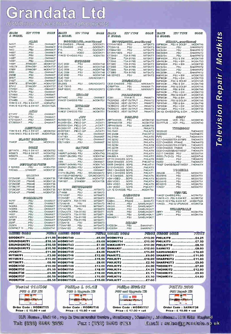
G rra t t Glistrib, &dol- of eleGtr nic eoinponents
SEGUrIll GreITYPQ 60 M OUGOXI
eillai Z1 (MY liWIA4 cooDeL
A LBA
@D M
1452T PSU ONWAKIT 14271 PSU ONWAKIT 1402 PSU ONWAKIT 1455T PSU ONWAKIT 1456T PSU ONWAKIT 1458T PSU ONWAKIT 14591 PSU ONWAKIT 1499Y STANDBY MODKIT37 14SLTX STANDBY MODKIT37 1799Y STANDBY MODKIT37 2002 PSU ONWAKIT 20096 PSU ONWAKIT 20521 PSU ONWAKIT 2152T PSU ONWAKIT 2099TX STANDBY MODKIT37 BTV17 STANDBY MODKIT37 CTV501 PSU ONWAKIT CTV701 PSU ONWAKIT CTV840 PSU ONWAKIT CTV841 PSU ONWAKIT CTV485 PSU ONWAKIT 11AK19 4:3 ..PSU & EW KIT MODKIT52 11AK19 16:9 PSU & EW KIT ...MODKIT52A
A ral CT1417 PSU ONWAKIT CT2159U PSU ONWAKIT CT2162UNT PSU ONWAKIT CT2863UNT PSU ONWAKIT
11AK19 4:3 ..PSU & EW KIT MODKIT52 11AK1916:9..PSU & EW KIT ....MODKIT52A
Da.neel 17 M01900C) 11AK37 PSU MODKIT51
O VON 2871NTX PSU á EW KIT MODKIT52 WS6673 PSU & EW KIT MODKIT52 WS6674 PSU MODKIT51 11AK37 PSU MODKIT51
Ee waifenacgo F SERIES PSU MODKIT30 TVC563 STANDBY MODKIT37
GOLDSTAR CF25A5OF FRAME MODKIT36 CF25C22C FRAME MODKIT35 CF28A5OF FRAME MODKIT36 CF28C22F FRAME MODKIT35 CF28C28F FRAME MODKIT36 CF29C42F FRAME MODKIT35
0 147 71 PSU ONWAKIT 1491 PSU ONWAKIT 1430RA PSU ONWAKIT 1430R5 PSU ONWAKIT 1430RW PSU ONWAKIT 14501 PSU ONWAKIT 14551S PSU ONWAKIT 2019R PSU ONWAKIT 20291 PSU ONWAKIT 2029TA PSU ONWAKIT COMPACT 11 PSU MODKIT47
GOOD MAN
HICJIZIX KIF? TYPI @OCX4 à Sl as),11
O ODDaln eà..coco ftwoaxe F16 CHASSIS .FRAME GOODKIT1 F16 CHASSIS .LINE GOODKIT1 F16 PSU GOODKIT1 F16 VIDEO GOODKIT1 11AK37 CHASSIS PSU MODKIT51
0 2VII MO CUC 2050 PSU MODKIT48 CUC 2051 PSU MODKIT48 CUC 2058 PSU MODKIT48 CUC 2059 PSU MODKIT48 CLIC 2080 PSU MODKIT48 CUC 7350 GRUNDIGKIT1 CUC 7301/3 BUZ90) PSU GRUNDIGKIT2 CLIC 7301/3 MJF18004) PSU GRUNDIGKIT3
averma HIT14RC PSU ONWAKIT 11AK37 CHASSIS PSU MODKIT51
gagiiM MO 28W440N PSU MODKIT54 11AK37 CHASSIS PSU MODKIT51
cn e AV29SX1EK . .FIELD 0/P AV29SX1EN FIELD 0/P AV29SX1EN1 FIELD 0/P AV29SX1PF FIELD 0/P AV29TSIE1 FIELD 0/P 14E1EK PSU C14T1EK PSU 21ET1EK PSU S21M3EK PSU
JVCKIT1 JVCKIT1 JVCKIT1 JVCKIT1 JVCKIT1 ONWAKIT ONWAKIT ONWAKIT ONWAKIT
M irgebeg 1455 PSU ONWAKIT 1496R/T (H3N90) PSU MODKIT43 1496R/T (BUZ90) PSU MODKIT44 1498 PSU ONWAKIT 2086 PSU ONWAKIT 2096R/T (H3N90) PSU MODKIT43 2096R/T (BUZ90) PSU MODKIT44 2098 PSU ONWAKIT 21V1N (BUZ90)....PSU GRUNDIGKIT2 21V1T(MJF18004) PSU GRUNDIGKIT3 TVR180R/208 .. STANDBY MODKIT37 TVR185T STANDBY MODKIT39
B e e nügel0 AV1 SERIES PSU MITSKIT3 CT1M5B PSU MITSKIT3 CT21M5BT PSU MITSKIT3 725M5BT PSU MITSKIT3 CT21A2STX. TDA 8178S MITSKIT1 CT21AX18 PSU MITSKIT3 CT21A3STX . TDA 8178S MITSKIT1 CT21AV1BS PSU MITSKIT3 CT25A2STX. TDA 8178S MITSKIT1 CT25A3STX TDA 8178S MITSKIT1 CT25A4STX TDA 8178S MITSKIT1 CT25A6STX TDA 8178S MITSKIT1 CT25AV1B PSU MITSKIT3 CT25AV1BS PSU MITSKIT3 CT25AV1BD PSU MITSKIT3
mince ffIre 77541 6C eff MOVCX86
e elK30000.,.*ealtimeoeig CT25AV1BDS PSU MITSKIT3 CT28AV1B PSU MITSKIT3 CT28AX1BD PSU MITSKIT3 CT28AV1BDS PSU MITSKIT3 CT29AS1 TDA 8178S MITSKIT2 CT29A4 TDA 8178S MITSKIT2 CT29A6 TDA 8178S MITSKIT2 CT29B2 TDA 8178S MITSKIT2 CT29B3 TDA 8178S MITSKIT2 CT2966 TDA 8178S MITSKIT2 CT33B3 TDA 8178S MITSKIT2 M5 SERIES PSU MITSKIT3
II MIN EE MO CE25 CHASSIS. .PSU NIKKAIKIT1 C289FTXN PSU NIKKAIKIT1 C28F41FXN PSU NIKKAIKIT1
cemegeotne IC561 TDA 8175 PANKIT1 TX25XD60 ..VERT OUTPUT PANKIT2 TC28XD60 ..VERT OUTPUT PANKIT2 TX28XD70 .VERT OUTPUT PANKIT2 TX29XD70 ..VERT OUTPUT PANKIT2 TX-W26D3 ..VERT OUTPUT PANKIT2
ecaneo 28PT4457/05 PSU MODKIT50 28PW5407/05 PSU MODKIT50 28PW6006/05 PSU MODKIT50 310.10708 PHILKIT3 310.20491 PHILKIT2 310.20496 PHILKIT10 310.31994 PHILKIT6 310.32252 PHILKIT5 310.32253 PHILKIT4 310.32254 PHILKIT9 310.32255 PHILKIT7 310.32262 PHILKIT8 310.62264 PHILKIT1 ANUBIS A SOPS PHILKIT2 CP110 CHASSIS SOPS PHILKIT8 G90A CHASSIS SOPS PHILKIT10 G90B CHASSIS SOPS PHILKIT10 G110 CHASSIS SOPS PHILKIT3 GR2.1 CHASSIS SOPS PHILKIT1 GR2.2 CHASSIS SOPS PHILKIT1 D-16 CHASSIS SOPS PHILKIT6 HSM VIDEO SOPS PHILKIT5 JSM VIDEO SOPS PHILKIT4 KSM VIDEO SOPS PHILKIT9 LSM VIDEO SOPS PHILKIT7 L01.1E CHASSIS PSU MODKIT50
CaZIOVII0 CI5944 FRAME SAMKIT2 CI6844 FRAME SAMKIT2 VIK310 PSU SAMSUNGKIT VIK320 PSU SAMSUNGKIT VIK350 PSU SAMSUNGKIT VI375 PSU SAMSUNGKIT VI395 PSU SAMSUNGKIT WINNER 1 PSU SAMSUNGKIT
gto ffle 51CSO3H PSU SHARPKIT1 51CS05H PSU SHARPKIT1
..eoci etocue£ 56FW53H ....PSU & DOLBY MODKIT45 59CS03H PSU SHARPKIT2 59CSO5H PSU SHARPKIT2 59CSD8H PSU SHARPKIT2 59DS03H PSU SHARPKIT3 59FW53H PSU & EW MODKIT49 28HW53H PSU + EW MODKIT53 56FW53H PSU + EW MODKIT53 66CS03H PSU SHARPKIT2 66CSO5H PSU SHARPKIT2 66CSD8H PSU SHARPKIT2 66EW53H PSU + EW MODKIT53 66FW53H PSU + EW MODKIT53 66FW53H ..PSU & DOLBY MODKIT45 66FW53H PSU & EW MODKIT49 66FW54H .PSU & DOLBY MODKIT45 66FW54H PSU & EW MODKIT49 66FW63H PSU + EW MODKIT53 76FW53H ..PSU & DOLBY MODKIT45 76FW53H PSU & EW MODKIT49 76FW54H ..PSU & DOLBY MODKIT45 76FW54H PSU & EW MODKIT49 76FW53H PSU + EW MODKIT53 76FG64H PSU + EW MODKIT53 DA-100 CHASSISPSU & EW MODKIT49
CCe97 SLV715HB VCR - PSU MODKIT40 SLV777UB VCR - PSU MODKIT40
171PIC MOC UI 35029400 THOMKIT2 35065920 THORNKIT1 FV70 PSU THORNKIT1 ICC7 CHASSISTDA 8178FS THOMKIT1 ICC7 CHASSIS FRAME THOMKIT3 ICC8 CHASSISTDA 8178FS THOMKIT1 ICC8 CHASSIS FRAME THOMKIT3 ICC9 CHASSISEAST/WEST THOMKIT4 ICC17 CHASSIS PSU MODKIT41 ISS20 (TV-DVD) PSU MODKIT46 R3000 PSU THOMKIT2 R4000 PSU THOMKIT2 TX92F CHASSISEAST/WEST THOMKIT4
F eD ellfe 28N2313 PSU MODKIT51 BD25815 PSU MODKIT51 BD2851S PSU MODKIT51 BD2951S PSU MODKIT51 BD3251S PSU MODKIT51 11AK37 PSU MODKIT51
IffleFige. 11AK37 CHASSIS PSU MODKIT51 11AK19 4:3 PSU & EW KIT MODKIT52 11AK19 16:9 PSU & EW KIT ....MODKIT52A 11AK33 PSU & UPGRADE ....MODKIT54
28PF 1 32PF 1
PSU MODKIT54 PSU MODKIT54
Oe(-9Éj/ Pl2g eg 211 HI,2 (CC)Dà'
GOODKIT1 £11.00
GRUNDIGKIT1 £10.50
GRUNDIGKIT2 £10.50
GRUNDIGKIT3 £10.50
JVCKIT1 £11.00
MITSKIT1 £3.00
MITSKIT2 £15.00
MITSKIT3 £6.00
MODKIT30 £10.00
MODKIT35 £9.50
MODKIT36 £5.00
MODKIT37 £6.50
MODKIT39 £8.50
MODKIT40 £6.00
MODKIT41 £6.00
MODKIT43 £7.00
MODKIT44 £7.00
MODKIT45 £4.00
MODKIT46 £12.00
MODKIT47 £15.50
MODKIT48 £8.00
MODKIT49 £13.00
MODKIT50 £18.00
MODKIT51 £10.00
MODKIT52 £15.00
MODKIT52A £15.00
C)2D112 CCOD2 22[161N c ec eci (COCa P2 M2
MODKIT53 £13.00
MODKIT54 £15.00
NIKKAIKIT1 £12.00
ON WAKIT £12.00
PANKIT1 £15.00
PANKIT2 £9.00
PHILKIT1 £10.00
PHILKIT2 £2.50
PHILKIT3 £4.00
PHILKIT4 £4.25
PHILKIT5 £5.75
PHILKIT6 £5.50
PHILKIT7 £7.60
PHILKIT8 £4.25
PHILKIT9 £7.50
PHILKIT10 £8.50
SAMKIT2 £8.00
SAMSUNGKIT £16.00
SHARPKIT1 £11.00
SHARPKIT2 £11.00
SHARPKIT3 £9.00
THOMKIT1 £7.00
THOMKIT2 £12.00
THOMKIT3 £9.00
THOMKIT4 £4.00
Visterie 9 il agg eli
POU à ,g1VI =hl
Slmillfdeeligture
Order Code : MODKIT55 Prlce: £ 15.00 + vat
1 09.9à. iéeV 4% Q uitte» alln
im ored Pic fur
Order Code : MODK T56 Price : £ 15.00 + vat
A na a mi negpsÉls G029 âsceile
at efi A Q PS K YB 2500 Philips
Simulatedeleeture
Order Code : MODKIT57 Price : £ 17.00 + vat
- 711 1 Sim agedeeeture
Order Code : SATKIT38
Price : £ 10.00 + vat
Television
ft4 House untwile tin Tâh. C3gA
(camic lYtm çç; IC'âC.1) eCe3 C39â(t
,v&jualb ,[41
auâil0 ellâ ejçjnacicItÉkti.icc Id u k

distributor of electronic cou 1 ponetds 7®wepcairlauri ,DDOclagluagi &,CtuCticxia
OpliDDIA1)(_C C4CeCe
Spare tip 0 5.3 mm
Spare tip 0 3.0 mm
Spare tip 0 3.0 mm 45°
Spare tip 0 2.0 mm
Spare Sponge
_ eriSt
Vicen 0.80mm 1.50mm 2.00mm
2.50mm
0.80mm
1.50mm
2.00mm
2.50mm
2.50mm
3.00mm
1.50mm
2.00mm
Adjustable by a potentiometer with Digital read out
Temperature range: 160iC to 480 C
Heater voltage : 24 Volt
Heater power : 48 Watt
Order Code : HQSOLDER30 Price: 35.00 + vat
Carriage charged at £ 5.00 + vat
Pr15.
HQTIP1 £ 2.00 + vat
HQTIP2 £ 2.00 + vat
HQTIP3 £ 2.00 + vat
HQT1P4 £ 2.00 + vat
HQSPONGE £ 0.50 + vat
,11I(e4.r.),,ej Mkke*ei ijth
1.6m 1.6m
1.6m
1.6m
3.0m
3.0m
3.0m
3.0m
15m
15m
30m
30m
WICKS1 £ 0.75 + vat WICKS2 £ 0.80 + vat
WICKS3 £ 0.90 + vat
WICKS4 £ 1.00 + vat
WICKM1 £ 1.00 + vat
WICKM2 £ 1.20 + vat
WICKM3 £ 1.30 + vat
WICKM4 £ 1.40 + vat
WICKL4 £ 6.00 + vat
WICKL5 £ 7.00 + vat
WICKL2 £ 8.00 + vat
WICKL3 £ 10.00 + vat
•DC) CDICC geoacicarrflaD &,c)11 loD OeDca I 0eAt &5Ceracg
Comes with a 3.2mm Sloped Tip
Picture Ilustration
Order Code : TS130 Order Code : TSSO9 Price : £ 8.00 + vat A Price : £ 2.00 + vat
-15 p1,11 eDdliGteln:.j 9 ri tIfJ-
10 m m x 3.2mm Sloped Tip Order Code : TSB32 Price: £ 1.50 + vat
10mm x 0.5mm Clonical Tip Order Code : TSB05 Price: £ 1.50 + vat
iir & a Mit7d1
18 SWG 500 grammes
20 SWG 500 grammes
22 SWG 500 grammes
exol,
SI10 £ 5.00 + vat
Sill £ 6.50 + vat
S112 £ 7.00 + vat
Ilk Carriage charged at £ 2.00 + vat ‘
" £ 5.00 + vat for 3 or more P.-. ' :
3 1/2 digits LCD Display
Low Battery indication
Transistor Testing Socket
Audible continuity
Technical Specifications:
DC Voltage: 200mV, 2V, 20V. 200V, 1000V
AC Voltage: 200mV, 2V, 20V, 200V, 750V
DC Current:20uA.200uA,2mA,20mA,200mA,2A,10A
AC Current: 200uA, 2mA, 20mA, 200mA, 2A, 10A
Resistance: 200R, 2K, 20K, 200K, 2M, 20M, 200M
!or
3 1/2 digits LCD Display
Low Battery indication
Transistor Testing Socket
Audible continuity
Technical Specifications:
DC Voltage: 200mV, 2V, 20V. 200V, 1000V
AC Voltage: 200mV, 2V, 20V, 200V, 750V
DC Current:20uA,200uA,2mA,20mA,200mA,2A,10A
AC Current: 200uA, 2mA, 20mA, 200mA, 2A, 10A
Resistance: 200R, 2K, 20K, 200K, 2M, 20M, 200M
Capacitance: 2nF, 20nF, 200nF, 2uF, 20uF
3 1/2 digits LCD Display
Low Battery indication
Transistor Testing Socket
Audible continuity
Technical Specifications:
DC Voltage: 200mV, 2V, 20V. 200V, 1000V
AC Voltage: 200mV, 2V, 20V, 200V, 750V
DC Current:20uA,200uA,2mA,20mA,200mA,2A,10A
AC Current: 200uA, 2mA, 20mA, 200mA, 2A, 10A
Resistance: 200R, 2K, 20K, 200K, 2M, 20M. 200M
Capacitance: 2nF, 20nF, 200nF, 2uF, 20uF
Frequency: 2kHz, 20kHz
Order Code : METER01 Order Code : METER02 Price: £ 11.00 + vat Price: £ 14.00 + vat
Carriage charged at £ 3.00 + vat Carriage charged at £ 3.00 + vat
Order Code : METER03 Price : £ 17.00 + vat
Carriage charged at £ 3.00 + vat

distributor of electronic component 48
,DIa M)e0gaGw amp0111®ye UHF TV and FM radio antenna preamplifiers designed for
professional aerial installers.
1 way amplifiers come with screw terminals
2 and 4 way amplifiers come with F connectors
Requires 12V DC power supply connected via a downlead
Description
1 way UHF TV Masthead Amplifier - 15dB Gain
Order Code : 2783ORPrice : £ 4.30 + vat
1 way UHF TV Masthead Amplifier - 26dB Gain
Order Code : 27831RPrice z £ 4.50 + vat
2 way UHF TV Masthead Amplifier - 10dB Gain
Order Code : 27837RPrice : £ 9.00 + vat
4 way UHF TV Masthead Amplfier - 10dB Gain
Order Code : 27838RPrice : 9.50 + vat
4 way UHF TV & FM Masthead Amp -10dB Gain
Order Code : 27839RPrice : £ 10.00 + vat
Masthead Amplifier Power Supply
Order Code : 27832RPrice : £ 5.00 + vat
Carriage charged at £ 2.00 + vat or £ 6.00 + vat for 2 or more
Mottene:-:,- iii 1.J J
egw ece &idle 'hem IOW
Signal/noise ratio of 0.6dB.
Feedhorn: 40 mm
Input Frequency 10.7 - 12.75 GHz
Order Code: LNBSINGLE
Price: £ 5.00 + vat
11 ......•••••••••11.1•010.
Signal/noise ratio of 0.7dB.
Feedhom: 40 mm
Input Frequency 10.7 - 12.75 GHz
Order Code: LNBTWIN Price: £ 14.00 + vat
:9Uüql(f=v Compact design - Backlit meter scale
Audible signal strength reading
Adjustable level control
Adjustable sensitivity adjustment
Frequency Range : 950 - 2250Mhz
Order Code : 27880R Price: £ 10.00 + vat
DIDItee co in pedelC2® ¿® g Receives both digital and analogue signals
For poor to weak strength signal areas
Robust design for low wind loading - 2 peices boom with aluminium wire rod elements
Supplied with F connector and clamp for horizontal and vertical (fits up to 57mm masts)
Ideal for areas with bad picture ghosting
Supplied part assembled - no tools required
Order Code : 27884R Price: £ 20.00 + vat Carriage charged at £ 6.00 + vat
DlieeZeoClow zebie nlcacie
Description
2 way
2 way with Bypass
4 way
4 way with Bypass
6 way
6 way with Bypass
8 way
8 way with Bypass
Gain
18dB
6dB
12dB
6dB
12dB
6dB
A range of Aerial amplifers designed to
allow distribution of TV, Satellite and FM signal without the loss of picture and sound quality.
Available with intergrated Digital bypass - to allow the use of SKY'digieye (13).
Main Operated , comes with full instructions
Order Code
SLX2
SLX2B
SLX4
SLX4B
SLX6
SLX6B
12dB SLX8
6dB SLX8B
Carriage charged at £ 2.00 +
Vaúlteserzt e Cbswe .2.0D
Signal/noise ratio of 0.7dB.
Feedhorn: 40 mm
Input Frequency 10.7 - 12.75 GHz
Order Code: LNBQUAD Price: £ 25.00 + vat
Price
£ 8.00 + vat
£ 9.25 + vat
£ 13.00 + vat
£ 14.00 + vat
£ 18.00 + vat
£ 19.00 + vat
£ 18.50 + vat
£ 20.00 + vat
vat or £ 6.00 + vat for 2 or more
VCOYY .É.Ol)g
Q uoC eD MID
For use with Multiswitches Signal/noise ratio of 0.7dB.
Feedhorn: 40 mm Input Frequency 10.7 - 12 75 GHz
Order Code: LNBQUATTRO Price : £ 15.00 + vat
ti)-a/ yll) 1F111.« Zer w -rye® P114:pc
tBaillem Order Code : PLG51
Bag of 10 Price : £ 1.25 + vat
Bag of 100 Price: £ 9.00 + vat
Order Code: PLG62
Bag of 10 Price : £ 1.60 + vat
Bag of 100 Price : £1250+ vat
9 5.1
Order Code : PLG101
Bag of 10 Price: £ 1.00 + vat
Bag of 100 Price: £ 6.00+ vat
thi;,tik eVq @Vi Onglym tecabem â1
[à Y â,YAâe h u(@u( lk This advertisement is just a selection of our stock.
Please contact us if you cannot find the part you are looking for.
' Please add £1 pp and VAT to all orders (Unless Otherwise stated) • All components are brand new • We accept payment by Access , Switch , Visa , Cheque and Postal Order
• All prices quoted are subject to availabilty and may be changed without prior notice
, ffl3le,[1-bp
1(DâC)) i3e)C) tsdn .southwp,
eux 020) 8903 6126
E & OE
âmel ârahdeb
Aerial Installation Accessories
d
0. u k
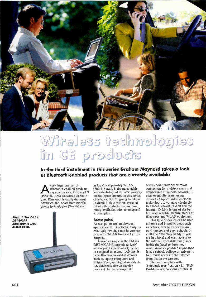
In the third instalment in this series Graham Maynard takes a look at Bluetooth-enabled products that are currently available
Avery large number of Bluetooth-enabled products are now on sale. Of the PAN
(Personal Area Network) technolo-gies, Bluetooth is easily the most advanced and, apart from mobile-phone technologies (WANs) such
Photo 1: The 0-Link DBT-900AP Bluetooth-to-LAN access point.
as GSM and possibly WLAN (802.11b etc.), is the most stable and established of the new wireless technologies covered in this series of articles. So I'm going to take an in-depth look at various types of Bluetooth products that are cur-rently available, with some specif-ic examples.
Access points Access points are an obvious application for Bluetooth. Only its relatively low data rate in compar-ison with WLAN limits it for this purpose. A good example is the D-Link
DBT-900AP Bluetooth-to-LAN access point (see Photo 1), which is designed to extend LAN servic-es to Bluetooth-enabled devices such as laptop computers and PDAs (Personal Digital Assistants, i.e. electronic diary/calendar devices). In this example the
access point provides wireless connection for multiple users and devices in a Bluetooth network. It enables mobile users, using devices equipped with Bluetooth technology, to connect wirelessly to a local network (LAN) and the interne. D-Link is one of the bet-ter, more reliable manufacturers of Bluetooth and WLAN equipment. This type of device can be used
at home and in public areas such as offices, hotels, museums, air-port lounges and even schools. It could be extremely handy if you are in a hotel and want access to the internet from different places inside the hotel or from your room. Another possible application is at a school, college or university to provide access to the internet from inside the campus. The unit complies with
Bluetooth specification v1.1 (PAN Profile) — see previous articles. It
664 September 2005 TELEVISION

connects to the Ethernet with DHCP (Dynamic Host Configuration Protocol) assign-ment (see http://www.dhcp.org/). There is plug-and-play installation, so no driver is required, and a security function for user access and authorisation/authentication. Up to seven Bluetooth users can have simultaneous intemet/intranet access. The operating range is up to 20m, a very good Class 2 range. The unit works seamlessly with desktop/laptop PCs and PDAs. It sells for about £50-£70. Other interesting access points,
at prices ranging from £75-£225 depending on features, are the Axis Communications 9010, the Anycom Bluetooth AP-2002, Belkin's Bluetooth access point, the Sony PCGA-BM1 Bluetooth modem and the Possio Bluetooth-to-WLAN Gateway PX20, a Bluetooth to Wireless LAN gate-way enhanced with OSGI. As with all the devices men-
tioned in this article, you can use the interne and a search engine such as Google.com to find further information on the products.
Barcode scanners For a little under £400 you can purchase a barcode scanner that transmits the scanned information to a remote device using Bluetooth instead of leads. The best known manufacturer of such devices is Baracoda, a French company. A typical device, the BC2604
(see Photo 2), has many applica-tions including point-of-sale termi-nals, shop inventory, warehousing and delivery tracking — I'm sure you can think of others. The devices are based on CCD technol-ogy that's similar to that used in camcorders. The BC2604 has a CCD scanning distance of 1-7in. (2-5-18cm) and a Bluetooth radio range up to 500ft/150m, so it's a true Class 1 device. For batch oper-ation it can store up to about 3,000 bar codes. Power is from two AA NimH 1,800 rnAh rechargeable bat-teries, the claimed battery life being greater than 3,000 scans. Dimensions are 143 x 78.8 x 154.5mm and the weight 180g.
Car kits and car navigation products Because of legislation that forbids drivers using a mobile phone while driving, unless it's mounted in a fixed holder, this is one of the most popular applications of Bluetooth. There are various dif-ferent versions, from the simplest
hands-free devices such as head-sets (see later) and clip-on wire-less types that fix to your clothing to fully-fledged systems that inte-grate with the car electronics and provide voice dialling. With the latter the device stores a sample of the user's voice giving commands such as 'dial' or 'call' and saying the names of people in a phone directory. These systems allow other voice commands to config-ure the phone or the system, route-ing calls through, muting in-car entertainment etc. while a call is in progress, and providing other fea-tures. The most advanced supplier of
these devices is another French company, Parrot, whose units, unlike some other products on the market, work with many different models from various phone suppli-ers and also BlackBerry-type PDA devices. A typical hands-free device is the Parrot DriveBlue+ (see Photo 3), which sells for about £60 and is available from many stores and on-line. The great thing about this device is that it is installation-free, simply plugging into the 12V cigarette lighter in your car. With broad support for current
and future phones, users are assured of the benefit of features such as one-touch handling of all calls and voice-recognition han-dling. There are additional fea-tures, but whether they can be used depends on the phone's capa-bilities. They include redial, dual call, caller ID, private mode, also the so-called DriveBlue menu on your phone display if it's able to provide this. DriveBlue integrates advanced
digital signal processing electron-ics and software. The driver's voice is processed to remove back-ground noise and echo — noise-and echo-cancellation techniques are used — and as a result both the called and the caller get good-quality sound. But many Bluetooth hands-free units that are on the market have very poor noise- and echo-cancellation, and voice-dialling often doesn't work proper-ly — especially if the voice samples have been taken in the quiet and the user dials with the engine run-ning, or vice versa. The Parrot CK3100 hands-free kit
(see Photo 4) is a bit more advanced than the DriveBlue+. It can provide drivers with visual information and functions that they use with their mobile phones. Its display will show the phone book and caller ID infor-
Photo 3: The Parrot DriveBlue+ Bluetooth hands-free in-car phone system
Photo 2: The Baracoda BC2604 Bluetooth barcode scanner.
Parrot n +33148036060
Photo 4: The Parrot CK3100 hands-free in-car kit pro-vides visual information as well as routine mobile-phone functions.
mation when a call is received - with compatible handsets. The unit mutes the in-car sound during calls and uses fitted car stereo speakers. So it has to be installed professional-ly, either as a retro-fit or when the car is being manufactured. It sells for about £100.
TELEVISION September 2005 6b3

Photo 5: The Tom-Tom Model G0500 hands-free in-car satellite-navigation system.
Photo 6: The Belkin compact flash card with Bluetooth built in.
Photo 7: The Belkin combined PDA and PC Bluetooth adapter card.
Photo 8: The Anycom USB-240 adapter card for PCs.
10 CP., 10 SEI ..•Il
0 30,, II iH
A206 'Woold' wich Church Street
An interesting variant and a far more complex beast, from Tom-Tom, incorporates the hands-free function into an in-car satellite-navigation system (see Photo 5). You can buy one of these great devices, Model G0500, for about £500. I recommend that you take a look at it by going to http://www.blueunplugged.corn/
Products/TOMTOM_G0_500.aspx It's certainly a fascinating
approach and is an inexpensive way of getting a car satellite-navi-gation system without having to spend over £1,000 on integrated equipment or a retro-fit dashboard installation.
Computer cards, printer adapters and dangles A variety ut plug-in cards enable your PC, laptop etc. to send data to the outside world. Some computers have Bluetooth (and in many cases WLAN) built-in, so there is no need to expand your PC with these add-ons.
The most common type of adapter with Bluetooth is the PCMCIA card. There are compact flash cards that incorporate Bluetooth but these are less com-mon — they are normally used in PDAs that don't already have Bluetooth built in. The most com-mon way to add Bluetooth to your PC or other device is to use a Bluetooth USB adapter or USB dongle'. There are also RS232 dongles, but these are less com-mon. Belkin, one of the top makers of
these devices, does a compact flash card with Bluetooth that sells for about £60 (see Photo 6). With this you can print, transfer files to/from your PDA and exchange cards, among other things, free of cables. Be careful when buying this
type of device — you may have to check that your PDA meets the system requirements specified by the manufacturer. For the Belkin device these are a genuine Intel StrongARM SA-1110 processor, a compact flash Type II slot, and Microsoft Pocket PC2000 or PC2002. Also check that the profiles you
need are provided. The Belkin cards are very good and typically have generic access, service dis-covery, a serial port, LAN access, dial-up networking, generic object exchange, object push, file transfer, and synchronisation. With this type of device — and any other PC/PDA adapter card — you get a CD-ROM with software to install, a user manual and a quick installation guide. Belkin also produces a com-
bined PDA and PC adapter card (see Photo 7). This basically con-sists of a compact flash card and PCMCIA adapter shell into which the compact flash card plugs to convert it to a PC adapter card. Individual card-style PCMCIA
adapters are also available, from firms like Belkin, BrainBoxes (a UK company based in Liverpool), TDK, Anycom and Socket. A good example of a USB adap-
tor that simply plugs into the USB socket at the back of a PC (USB 1.1 or 2.0, check for compatibility) is the Anycom USB-240. It sells for about £30 — see Photo 8. It's easy to find cheaper products, but they don't all work as well or with as many devices and profiles. This USB adapter's range is also very good. Some of these adapters work up to only a few metres, but the USB-240 is a Class 1 device that works up to 100m. It uses
666 September 2005 TELEVISION
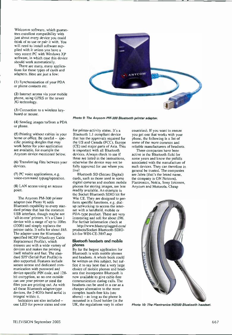
Widcomm software, which guaran-tees excellent compatibility with just about every device you could think of to use or pair it with. You will need to install software sup-plied with it unless you have a very recent PC with Windows XP software, in which case this device should work automatically. There are many, many applica-
tions for these types of cards and adapters. Here are just a few:
(1) Synchronisation of your PDA or phone contacts etc.
(2) Internet access via your mobile phone, using GPRS or the newer 3G technology.
(3) Connection to a wireless key-board or mouse.
(4) Sending images to/from a PDA or phone.
(5) Printing without cables in your home or office. Be careful — spe-cific printing dongles that may work better for your application are available, for example the Anycom device mentioned below.
(6) Transferring files between your devices.
(7) PC voice applications, e.g. voice-command typing/operation.
(8) LAN access using an access point.
The Anycom PM-300 printer adapter (see Photo 9) adds Bluetooth capability to every stan-dard printer that has the common USB interface, though maybe not 'all-in-one' printers. It's a Class 1 device with a range of up to 100m (330ft) and simply replaces the printer cable. It sells for about £65. The adapter uses the Bluetooth-specified HCRP (Hardcopy Cable Replacement Profile), which ensures use with a wide variety of devices and makes the printing itself reliable and fast. The stan-dard SPP (Serial Port Profile) is also supported. Features include secure access and dedicated com-munication with password and device-specific PIN code, and 128-bit encryption, so no one outside can use your printer or steal the files you are printing out. As with all these Bluetooth adapter-type devices, the 2.4GHz band aerial is integral within it. Indicators are also included —
one LED for power status and one
Photo 9: The Anycom PM-300 Bluetooth printer adapter.
for printer-activity status. It's a Bluetooth 1.1 compliant device that has the approvals required for the US and Canada (FCC), Europe (CE) and major parts of Asia. This is important with all Bluetooth devices. Always check to see if these are listed in the instructions, otherwise the device may not be fully approved for use where you live! Bluetooth SD (Secure Digital)
cards, such as those used in some digital cameras and modern mobile phones for storing images, are less readily available. An example is the Socket Bluetooth SDIO kit for Win CE. They are designed to per-form specific functions, e.g. dial-up networking to access the inter-ne with a handheld, mobile or PDA-type product. These are very interesting and sell for about £90. For further information check at http://www.blueunplugged.com/
products/Socket-Bluetooth-SDIO-kit-for-WIN-CE-3897.asp
Bluetooth headsets and mobile phones By lar the largest application for Bluetooth is with mobile phones and headsets. A whole book could be written on this subject, but suf-fice it to say here that a very large choice of mobile phones and head-sets that incorporate Bluetooth is now available to give cable-free communication during calls. The headsets can be used in a car as a cheaper alternative to the more complex hands-free kits (see above) — as long as the phone is mounted in a fixed holder (in the UK, the regulations vary in other
countries). If you want to ensure you get one that works with your phone, the following is a list of some of the more common and reliable manufacturers of headsets. These companies have been
active in the Bluetooth field for some years and know the pitfalls associated with the manufacture of such devices. They can therefore in general be trusted. The companies are Jabra (that's the brand name, the company is GN Netcom), Plantronics, Nokia, Sony Ericsson, Anycom and Motorola. Cheap
Photo 10: The Plantronics M2500 Bluetooth headset.
TELEVISION September 2005

Photo 11: The Nokia SI.1-113 Bluetooth pen (or Chatpen).
products, especially those on sale at market stalls, may not be prop-erly qualified for the Bluetooth specification and may work with only certain phones — or not at all! Steer clear of them: they are a false economy. The Plantronics M2500 is a typ-
ical Bluetooth headset (see Photo 10). It provides about five hours of talk time (time engaged in calls) and up to 120 hours of standby time (time spent in the low-power mode waiting for either incoming or outgoing calls to commence). The headset fits over your ear and can be adjusted for comfort. It sells for about £30. Only three-four years ago such headsets were in their infancy, had very low battery life and sold for about £150 — as much as £300 in some cases. They were in effect a gimmick for the businessman with a good expenses budget! They now sell in super-markets and are even in some cases given away at petrol stations. The M2500 headset has
Bluetooth v1.1 compliance (Class 2), i.e. a range of up to 10m. It supports headset and hands-free Bluetooth profiles, has the voice-dialling function, an LED indicator and a button for on/off and to receive/make calls. Plantronics headsets are of very good quality and work with almost every con-ceivable mobile phone. Once the headset has been paired with your phone it needs the minimum of effort, and clicks etc. to get voice
calls, both incoming and outgoing, routed through the headset instead of the phone. The Sony Ericsson T630 is a
typical mobile phone that incorpo-rates Bluetooth technology. It sells for about £75, typically on a SIM-free basis. Its many features are too numerous to list here. To find out more about Sony Ericsson mobile phone products, which are the best, most advanced, most styl-ish and reliable phones available by a considerable margin, check at the website www.sonyericsson.com New headsets that provide more
than just basic voice communica-tion are now beginning to appear. These Bluetooth stereo headsets use advanced new profiles and are capable of producing stereo-music quality from CD players and other consumer products, such as the new iPod MP3 players. In addition Bluetooth-enabled stereo speakers are becoming available for use with your domestic hi-fi equip-ment.
Pens The Bluetooth pen is an interesting device. Nokia produces one called the SU-1B (or Chatpen) that costs about £120 (see Photo 11). Basically it remembers what you are writing so that this can all be stored in your PC or other storage device. The data from the pen is transmitted wirelessly by Bluetooth.
The pen can remember up to 100 A5 sheets of text. Even the most prolific writers don't need to worry too much about running out of memory, because the pen con-nects smoothly with your PC where you can store your notes for further revision and distribution. Once properly paired, the Nokia Digital Pen also provides automat-ic connection to a compatible mobile phone, so you can send hand-written notes to compatible phones or email addresses via MMS (Multimedia Messaging Service). The pen can be connected to a
compatible PC via a USB cable. The battery provides up to two hours of writing time. There are three LED indicators and a vibra-tion alert to indicate pen and send status. Changeable ink cartridges are used, and the pen works as a normal one with non-digital paper. When connected to a compatible Nokia charger or a compatible Nokia travel charger the pen charges in its stand.
Summary As you can see from the above notes a large variety of CE and other products now feature Bluetooth technology. This article has only really scratched the sur-face. There are many more applica-tions, particularly in the industrial, medical and other fields. Even some camcorders, videos, digital cameras, set-top boxes and other domestic brown-goods products are starting to use the technology. I will look at specific examples of one or two of them next month. Zigbee is another up-and-com-
ing wireless technology I'll start to look at next month. The name comes from the zigging' motion of the bumblebee. It is starting to be used in home-networking type applications where a lower data rate than Bluetooth is acceptable and very low power is required, particularly in light-switch arrange-ments. This technology is nowhere near as well established as Bluetooth. Its protocol stack has only recently been ratified to form a full point-to-multipoint specifica-tion, but there's no doubt that it is going to be a very important tech-nology indeed. It will enable light switches to be fitted to walls wher-ever you want them, without hav-ing to channel through your walls for cables — and who needs that aggravation?
668 September 2005 TELEVISION

o
r-',ence
B‘ Booking Form ) Where building services meet technology
8th November 2005 Coventry University Technology Park
Date and Venue The conference will be held on Tuesday 8th November 2005 At Coventry University Technology Park
Conference fees Cost per delegate (Standard rate) £295
An 'early booking discount' of 10% will be applied if booked before Friday 16th September 2005
Recognised educational establishments will be offered special rates, please contact for details.
Fee includes: Conference attendance Full documentation/papers Lunch and refreshments
For booking and details Intelligent Buildings Conference 2005 Jean Bourne Media House, Azalea Drive, Swanley, Kent BR8 8HU UK
Tel: +44 (0) 1322 611209 Fax: +44 (0) 1322 616376 Email: [email protected]
For information on promotional opportunities contact:
Jill Harrington Tel: +44 (0) 1322 611259 Fax: +44 (0) 1322 616376 Email: [email protected]
Nexus Media Communications Ltd reserve the right to alter the timing, content or speakers of the conference
Priority Booking Form
You may cancel your registration with a full refund (less 15% administration charge) prior to 7th October 2005. Cancellations received after this date will be liable for full registration fee. Early booking discount if you book and pay before 16th September 2005
Please register me for Intelligent Buildings Conference 2005
Name.
Company: Job position.
Address.
Country
Telephone: Fax.
Signature
How To Pay Cheque or draft: Invoice: Credit Card:
Send with the form payable to 'Nexus Media Communications Ltd' Complete the form and we will send an invoice to you Complete the form with your credit card details
Please tick D £111 I enclose a cheque for
D Please invoice me. Purchase Order No
E Please charge my credit card (delete as appropriate) MastercardNisa/Amex
Card number: Expiry Date*
Name on card.
Signature.
Credit card billing address.
Date.
NEXUS ojF l MoJr\JR :1., II
• ›••• • Nexus M edia Co m munications Ltd Media House, Azalea Drive, Swanley, Kent BR8 8HU
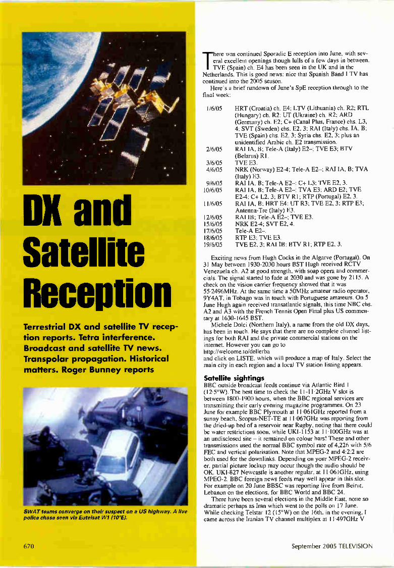
DX and Satellite Ruud°
im fflei
Terrestrial DX and satellite TV recep tion reports. Tetra interference. Broadcast and satellite TV news. Transpolar propagation. Historical matters. Roger Bunney reports
SWAT teams converge on their suspect on a US highway. A live police chase seen via Eutelsat W1 (10°E).
670
Th ere was continued Sporadic E reception into June, with sev-eral excellent openings though lulls of a few days in between. TVE (Spain) ch. E4 has been seen in the UK and in the
Netherlands. This is good news: nice that Spanish Band I TV has continued into the 2005 season. Here's a brief rundown of June's SpE reception through to the
final week:
1/6/05 HRT (Croatia) ch. E4; LTV (Lithuania) ch. R2; RTL (Hungary) ch. R2; UT (Ukraine) ch. R2; ARD (Germany) ch. E2; C+ (Canal Plus, France) chs. L3, 4; SVT (Sweden) chs. E2, 3; RAI (Italy) chs. IA, B; TVE (Spain) chs. E2, 3; Syria chs. E2, 3; plus an unidentified Arabic ch. E2 transmission.
2/6/05 RAI IA, B; Tele-A (Italy) E2—; TVE E3; BTV (Belarus) Rl.
3/6/05 TVE E3. 4/6/05 NRK (Norway) E2-4; Tele-A E2—; RAI IA, B; TVA
(Italy) E3. 9/6/05 RAI IA, B; Tele-A E2—; C+ L3; TVE E2, 3. 10/6/05 RAI IA, B; Tele-A E2—; TVA E3; ARD E2; TVE
E2-4; C+ L2, 3; BTV R1; RTP (Portugal) E2, 3. 11/6/05 RAI IA, B; HRT E4; UT R3; TVE E2, 3; RTP E3;
Antenna-Tœ (Italy) E3. 12/6/05 RAI IB; Tele-A E2—; TVE E3. 15/6/05 NRK E2-4; SVT E2, 4. 17/6/05 Tele-A E2—. 18/6/05 RTP E3; TVE E3. 19/6/05 TVE E2, 3; RAI IB; BTV RI; RTP E2, 3.
Exciting news from Hugh Cocks in the Algarve (Portugal). On 31 May between 1930-2030 hours BST Hugh received RCTV Venezuela ch. A2 at good strength, with soap opera and commer-cials. The signal started to fade at 2030 and was gone by 2115. A check on the vision carrier frequency showed that it was 55.2496MHz. At the same time a 50MHz amateur radio operator, 9Y4AT, in Tobago was in touch with Portuguese amateurs. On 5 June Hugh again received transatlantic signals, this time NBC chs. A2 and A3 with the French Tennis Open Final plus US commen-tary at 1630-1645 BST. Michele Dolci (Northern Italy), a name from the old DX days,
has been in touch. He says that there are no complete channel list-ings for both RAI and the private commercial stations on the interne. However you can go to http://welcome.to/dellerba and click on LISTE, which will produce a map of Italy. Select the main city in each region and a local TV station listing appears.
Satellite sightings BBC outside broadcast feeds continue via Atlantic Bird 1 (12.5°W). The best time to check the 11-11.2GHz V slot is between 1800-1900 hours, when the BBC regional services are transmitting their early evening magazine programmes. On 23 June for example BBC Plymouth at 11.061GHz reported from a sunny beach, Scopus-NET-TE at 11-067GHz was reporting from the dried-up bed of a reservoir near Rugby, noting that there could be water restrictions soon, while UKI-1153 at 11-100GHz was at an undisclosed site — it remained on colour bars! These and other transmissions used the normal BBC symbol rate of 4,226 with 5/6 FEC and vertical polarisation. Note that MPEG-2 and 4:2:2 are both used for the downlinks. Depending on your MPEG-2 receiv-er, partial picture lockup may occur though the audio should be OK. UKI-827 Newcastle is another regular, at 11.061GHz, using VIPEG-2. BBC foreign news feeds may well appear in this slot. For example on 20 June BBSC was reporting live from Beirut, Lebanon on the elections, for BBC World and BBC 24. There have been several elections in the Middle East, none so
dramatic perhaps as Iran which went to the polls on 17 June. While checking Telstar 12 (15°W) on the 16th, in the evening, I came across the Iranian TV channel multiplex at 11.497GHz V
September 2005 TELEVISION

(17,468, 3/4) whose content seems to have increased in recent times. In total ten channels are available, with video quality that varies from fair to really poor. I'm not sure for whom the multi-plex is intended — US cable networks perhaps? The channel listing is Appadana, Pars, NITV, Gunaz TV, Channel One, Lahse, Your TV, Rang a Rang, Payam TV and Marrom TV, the latter with only colour bars. They operate as Iranian Media Alliance and are trans-mitted via Globecormn TV. As received, the digital parameters are SR 17,468 and FEC 3/4, though one channel clearly captioned the parameters as 19,279 and 2/3. When I checked all the channels other than Pars carried party political broadcasting, phone-ins, talking to camera etc. The content of Pars is decidedly dramatic, and is continuously repeated. President Bush was seen speaking for several seconds, with Arabic subtitles, followed by revolution-ary singing. The scene changed to a large group, into which blind-folded prisoners (hostages?) were dragged. They were each shot several times. The scene then changed to the bodies being behead-ed by a man with a very blunt machete. He waved a head in the air before placing it on the torso. The audio was grim. Onlookers cheered as the man hacked away noisily, the floor awash with blood. The poor VHS video quality did little to dilute the real hor-ror of this brutality. The main political news in Europe concerned the Brussels EU
budget, which dragged on for many days during June. There was a regular hook-up via Eutelsat W2 (16°E) at 12.525GHz H (5,632, 3/4), used by Sky News and others — courtesy UKI-818 SISLink. Another long-running drama unfolded via the Eutelsat WI
(10°E) UP4 feeder (10.972GHz V, 4,167, 5/6) with the Michael Jackson trial and the verdicts. Of more interest technically was the drive by Jackson to the courthouse to hear the verdict announce-ments. This was covered from the moment he left his house, the procession of four black limousines being followed all the way to the courthouse by an 'eye in the sky'. From the fading and signal dropouts the sky-to-ground link was clearly analogue and not digi-tal. There was eye in the sky drama via UP4 on 14 June, with a
hell-c am hovering over New York's East River. A small helicopter had flipped over and crashed into the water. Rescuers scrambled to help, and all those in the helicopter were rescued. The latter was left submerged, tied to a pontoon to prevent it drifting in the strong current. Three days later another chopper crashed into the East River, on a pleasure flight. Another well-rehearsed rescue, with all surviving. The pictures were received via UP4, using the WABC-7 heli-cam. Another live drama via UP4 unfolded on June 7. This time
SWAT teams had pinned a criminal in his people carrier against a motorway wall, blocking all escape. There was a stand-off for over an hour, then a tear-gas grenade was fired into the vehicle. The suspect opened the door and a police dog leaped inside, pulling him out. SWAT members then 'subdued' him — he was eventually carried away by stretcher. The heli-cam had circled at the lowest permitted height of 2,000 feet. The live police chases I've seen via Atlantic circuits have always been just as we see them in the movies. June, hot weather, no downpours so far and it's Wimbledon
again. An encrypted OB multiplex via Eutelsat W2, at 11.140GHz H (22,218, 5/6), was established for the duration of the event. Interesting that the various courts had their own channels in the multiplex — catalogued as Ch2 Centre Court', Ch3 Court l', Ch4 Court 2', Ch5 Court 3' and Ch6 court 6'. There was an internal identification, 'Digital OU mux'. Another sports multiplex, for basketball action, has been estab-
lished by the NBA via the little-used Intelsat 901 (18°W). It had previously been carried by Atlantic Bird 1 (12.5°W). The new ser-vice is encrypted and uses up to three channels, depending on the content required by European broadcasters. There are NBA TV Europe at 11•664GHz, NBA Path 2 English at 11•672GHz and NBA Finals at 11•680GHz — all with horizontal polarisation, SR 5,632 and 3/4 FEC. Finally in mid-June Sky News used Europe*Star 1 (45°E) for
A Bahrain radio promotional slide, seen via Arabsat at 26'E.
several live Johannesburg-Isleworth newsfeeds. They were trans-mitted by GlobeCast Africa at 11•522GHz V (6,109, 3/4).
Tetra interference Tetra is being rolled out across the UK. Most police forces are now using 380-385MHz (mobiles) and 390-395MHz (base sta-tions) instead of the old 450-454MHz analogue band. There are specific 'direct-mode' channels in a two by six frequency block between 380.0125-380-1375MHz and 390.0125-390.1375MHz. The transmissions are all in an encrypted digital form, so your Radioshack scanner will hear only curious sharp buzzes in this band. But Tetra can cause interference to TV reception, particularly
when a wideband aerial amplifier or domestic distribution amplifi-er is in use near a Tetra installation. Appropriate UHF bandpass filtering or bandstop/notch filtering must be used to eliminate the breakthrough.
Broadcast news Solent TV: The Isle of Wight RSL TV station (ch. 54 H) has opted for Astra digital satellite space, where it joins Sky at the end of the year. The cost of electronic programme guide access has fallen and, with its analogue RSL licence running out at the end of 2007, Solent TV has decided that it must go digital with satellite delivery. This will increase its coverage of course. Once its pro-gramming is on Sky, Solent TV hopes to provide greater tourist publicity.
France: The EU has confirmed that it will provide financing for a news channel, Chaim Francaise d'information Internationale, to be largely run by TFI and France Television. The aim of the chan-nel is to present the French viewpoint to overseas viewers. The channel is required to "apply market conditions to all commercial operations", which suggests that it will carry advertising, though profits have to be put back into public-service tasks.
Malaysia: A third TV channel, to provide general entertainment, news and educational programming, is to be launched in September 2006. The existing RTM1 and 2 networks are to start digital operation on a test basis.
Afghanistan: UNESCO is funding the Kabul Educational Radio/TV Centre, which has been running on a test basis since last year. Several programmes and 'social marketing' promotions have already been broadcast via the national TV service. The Japanese government financed the rebuilding and equipping of the main Kabul TV tower, with NHK providing technical assistance.
South Korea: The government is to fund a TV channel that will broadcast the proceedings in parliament, provide details of new
TELEVISION September 2005 671

A BBC feed from Beirut to London via Atlantic Bird 1 (12.5 W).
legislation and update viewers on emergency procedures. The new service will start in the southern Seoul region this December.
Syria: The state broadcasting monopoly is to be loosened, with the possibility of independent radio and TV stations opening in the near future.
Australia: The trade organisation Commercial Radio Australia is pushing for digital radio using the Eureka 147 system in L band, with a ten-year dual analogue/digital period initially. Tests of the system are being carried out in Paris.
Spain: The 50MHz amateur radio band has been widened to 50-51MHz across the country, with permitted power increased to 100W. Since there are still TV transmissions in Band I, amateurs have to apply for regional permission to go on-air.
Cuba: Because of inter-departmental arguments in Washington about funds, purchase of a C130 aircraft to transmit US material to Cuba, as part of the Radio and TV Marti project, has been delayed. Broadcasts continue from a tethered blimp moored at Key West, Florida.
Satellite news Intelsat has confirmed the successful launch of its IA-8 satellite which, at 89°W, will provide coverage from the Americas out as far as Hawaii. It's the first Intelsat craft to have Ka as well as C and Ku band capacity. IA-8 will be providing broadcast, HDTV, OB and broadband data-transmission services. The new satellite Apstar V1 came into operation in mid June,
taking over services via the ageing Apstar IA at the 134°E slot. It carries C and Ku band TV transmissions and telecommunications traffic across the Asia/Pacific region. It's fifty years since the Baikonur Cosmodrome opened. The
first Sputnik was launched two years later, in 1957. On 2 June the Kazakh government held an official celebration which was attend-ed by the president and also President Putin. A 24-hour news channel is being prepared to be broadcast across the US, Europe, Russia and SE Asia. To avoid a 'Russian bias', a group is being set up to monitor editorial policy. A four-channel Bulgarian multiplex is to be set up incorporating
the commercial channels Nova TV and BTV plus the state TV Bulgaria Satellite (BNT) and a music channel. There will also be several radio stations. The service will be encrypted, and the satel-lite to be used has still to be announced. Coverage is to include Europe, West Russia, North Africa and North America. The service will operate around the clock on a three eight-hour segment basis. Look out for KDN appearing on test cards now that Kenya
Data Networks has opened a telecommunications gateway near
Nairobi using Intelsat and NSS satellites. It went on air on 23 May.
Transpolar propagation An article in Six News, the magazine for 6m (50MHz) band radio amateurs, refers to transpolar propagation (F2 layer DX) during the sunspot peak in the winter of 2001-2. Transpolar signal propa-gation had previously been experienced at 28MHz, but became evident on many occasions at 50MHz during this period. Mainly, Finnish and Swedish amateurs were in contact with amateurs in British Columbia (Canada) and the mid-to-west US states - Oregon, Montana and the Dakotas. Reception generally occurred at about 2000 GMT. Those involved comment that signal quality varied from normal to having an auroral/rough tone. As solar outrages are more likely during a high sunspot period,
it's possible that the propagation included an auroral element. Tromso observatory noted that strong Auroral E (E layer) and Spread F was evident during the time of several though not all the reception reports. The signal distances are greater than a single hop, which makes me wonder whether a degree of auroral ducting was involved. A check on the path plots shows a remarkably nar-row 'opportunity angle' between the clusters. There were no reports from the UK but on 30 October 2003,
during an aurora that was visible here in the south of the UK, a check on the ch. A2-4 video carrier frequencies with an R7000 scanner plus Mutak preamplifier revealed a multiplicity of low-level signals. This suggests that AR propagation, although at low level, was present between the Americas and the UK, and could be received with a narrow-band tuner. For further information check http://home.planet.n1/-palsix.htm
Historical matters There's been quite a lot on wavefront tilt since I first mentioned the subject in the April issue. While looking through some back copies I found glowing testimonials for the four-element wave-front-tilted Telerection Maximus aerial in the February 1951 issue. The Cornish viewer quoted was, I assume, receiving ch. B5 from Wenvoe. Telerection ended its days at Weymouth as part of the Thorn Electrical group, being closed down despite a full order book for the UK and export markets. One of its final triumphs was a short back-fire UHF aerial. This was a high-gain, wideband sys-tem that was probably costly to produce because of its complex construction. Mention of J-Beam last month brought a recollection from a
reader of one of the company's most extraordinary aerials, a "fold-ing double-beam" type for Bands I and III. This had a skeleton-slot for Band III, with a single dual-band output from a common termination at the Band I dipole. There were dual, parallel direc-tor/reflector assemblies for Band III, while the Band I section had three elements. J-Beam went on to produce skeleton-slot aerials for UHF TV, UHF teleconuns and 435MHz amateur band use. While going through early issues I came across an advertise-
ment in October 1958 for what must have been the first 'satellite TV' receiver, the infamous ex-government R208. This six-valve single superhet covered 10-60MHz, i.e. much of Band I but also, as it went down past 20MHz, the bleeper beacon in the Sputnik satellites. The 19.995-20-010MHz band signal could be easily received during each satellite pass.
Worth reading Austin Uden, a noted researcher on weather-related tropospheric signal propagation and reception, tells me that copies of his two booklets on tropospheric DXing are still available. They are not theoretical texts but accounts of conditions that have been experi-enced, with hints on forecasting the weather and possible signal paths. A descriptive leaflet is available - please send a stamped, addressed envelope with requests. The books are available at £8 for the two including postage from A. Uden, 12 Hampden Close, Aylesbury, Bucks, HP21 8NS. I think they are very worthwhile reference works to have.
672 September 2005 TELEVISION
ELP Wanted: Original remote-control unit for the Sony Model SL-C9 VCR. Any condi-tion. Pleease phone Malcolm on 01279 813 727 or email [email protected] Wanted: A channel-change knob for the VHF tuner in the Sobell Model ST197DS. It's a dual-standard set that dates from 1964/5. The knob has VHF radio in three positions. A circuit diagram would be useful, also a scrap chassis if anyone has such a thing Can collect locally (thirty miles). Jim Littler, 363 Atherton Road, Hindley Green, Wigan, Lancs, WN2 3XD. Phone 079 9096 3918. Wanted: (1) A service manual or circuit dia-gram for the Sony C969 MP3 audio player. (2) The full service manual (not just the cir-cuit diagram) for the Telequipment oscillo-scope Model D65. A photocopy may be OK if legible. Cash settlement or will exchange for a different original manual that I may have and you may want. (3) An Advance P3
The help wanted column is primarily intended to assist readers who require a part, circuit etc. that's difficult to obtain. Requests are published at the discretion of the editor. Send them to the editorial department — do not write to or phone the advertisement department. If you have access to email they can be sent to [email protected]
signal generator Mk l-2 with US octal valves or a Mk3 with B9G valves, dating from the late 1950s. It need not be in working order but must be reasonably complete for renova-tion and reuse. Phone Alan Williams on 01745 812 642. Wanted: Quad 33, 34 or 44 preamplifiers, 405 power amplifiers and FM2, FM3 or FM4 tuners for spares. Also boards and modules for these. Contact Mike on 01758 613 790. Wanted: Could someone let me know the value of item Z463 (circuit reference num-ber) which is in series with the collector of Q460 in the Toshiba widescreen TV Model 28ZD26P? Please phone Brian on 020 8845 5123 or email [email protected] For disposal: A Pye valve radiogram dating from approximately 1952. Free to a collec-tor/enthusiast. It's in working order and the dark oak cabinet is in good condition. Must be collected unless local. Phone R. Weston on 0121 453 3786 (Rubery, Birmingham). Wanted: Old half-inch diameter ferrite rods. Must be six inches or more long. Will pay very good money for them. Peter Tankard, 16A Birkendale Road, Sheffield, S6 3NL. Phone 0114 231 6321 between 9 a.m. and 10 p.m.
For sale: Various Sanyo Betamax VCRs in the 'VTC5000-VTC5100 range. There are six in total plus some cassettes. All were in working order when stowed away a few years ago but present condition not known. £25 each, and they would have to be collect-ed from Denbigh in North Wales. Phone Alan Williams on 01745 812 642. Wanted: Older type combined aerial/earth connector plugs of the type that were avail-able in the UK in the late 1970s to early 1980s. The accompanying photo shows the connector. Please email James Eubanks at [email protected]
MI MI"
Poe Crui
•-•
Horizon Digital Satellite Meter
• Signal Strength and BER displayed together
• 32 Transpon.iers or 16 satellites, horizontal & vertical
• Audible tune-in, with back light • NB, C&Ku land, Mpeg, V Sat compatible
• Figure of 8 mains input connector. 2.1 mm Fe
th
Horizon Digita errestrial Me HDThl • Displays Signal Strength (R.F level) and Pre and Post BER together 32 pre programmed transmitters (via website) or all channel step through
• Audible tune-in, with back I et • Automatic constellation • RF Input range 167-862 Mili • Input dynamic range -72dEm--201g.
;4
I I
iN / gi
For a reliable solution.
www.horizonhge.com plug
o emember atellite Meters
Cost effective
Small and Compact Measure two vats at same time Self powered Ma rechargeable NIMH batteries Powered via built In batteries, charger or receiver
Also available from the following distributors Eurosat Midlands 01922 639299 www.eurosatmidiands.com Eurosat North 01924 423602 www.eurosatmidiands.com Gray Nottingham 0115 927 9993 www.grax.co.uk
Grao Manchester 0161 747 2007 www.grax.co.uk Gras Leeds 0113 26 33 500 www.grax.co.uk Solutions Group 08456 444 000 www.solutionsgroup-pic.com
Or contact Horizon direct for your local supplier
on +44 10120 8344 8230
or email [email protected]
TELEVISION September 2005 673

ntiargemepair
Ultra Coronation Twin
Fig. 1: Stages in the recon-struction of the tuning scale.
The Ultra Model R786 Coronation Twin, which has a four-valve plus metal rectifier line-up, is fairly well known amongst collectors of older radio receivers.
It was released in 1953 as a mains-battery portable and provides long and medium waveband coverage. The Bakelite case was built to house a 7-5V valve filament battery (filaments in series) with HT supplied by an
Malcolm Burrell turns his attention to a mains/battery portable receiver that dates from about 1953. It required both electronic and cabinet renovation
Appearance of the Ultra Coronation Twin receiver after attention to the cabinet and tuning scale.
85V battery. Mains operation is selected automatically by a changeover switch when the mains-input connec-tor is inserted. Generally today only mains operation is practical. For those who are unfamiliar with valves, it's worth
noting that most types made for battery operation are directly heated, i.e. the heater is also the cathode. There is no perceptible glow, and the warm-up time is typical-ly only about one-two seconds! While conventional valve terminology refers to a heater and a cathode, with directly-heated valves the term filament is used. I received a request to brighten the cabinet of one of
these sets, which had resided in a shed for a consider-able time. A total restoration was not envisaged, the idea being simply to preserve the set in a reasonable condition. I found that it didn't function, despite the suggestion
that it had done so recently. Investigation revealed that the smoothing capacitors were in doubtful condition. This was confirmed by a loud hum when power was supplied — because of loss of capacitance. There were no signals, and some essential components had been replaced during an earlier overhaul. The hum was sur-prising, as half the tapped filament of the DL94 output valve was open-circuit! Confident of being able to obtain a replacement
DL94 valve eventually, I turned my attention to the presentation.
Cabinet and tuning scale The tuning scale in this model is in two sections: a cream metal plate that bears most station names is attached to the chassis while a transfer, that indicates the wavelengths for both MW and LW, is applied to the lower part of the glass window. In addition to the cabi-
6 74 September 2005 TELEVISION
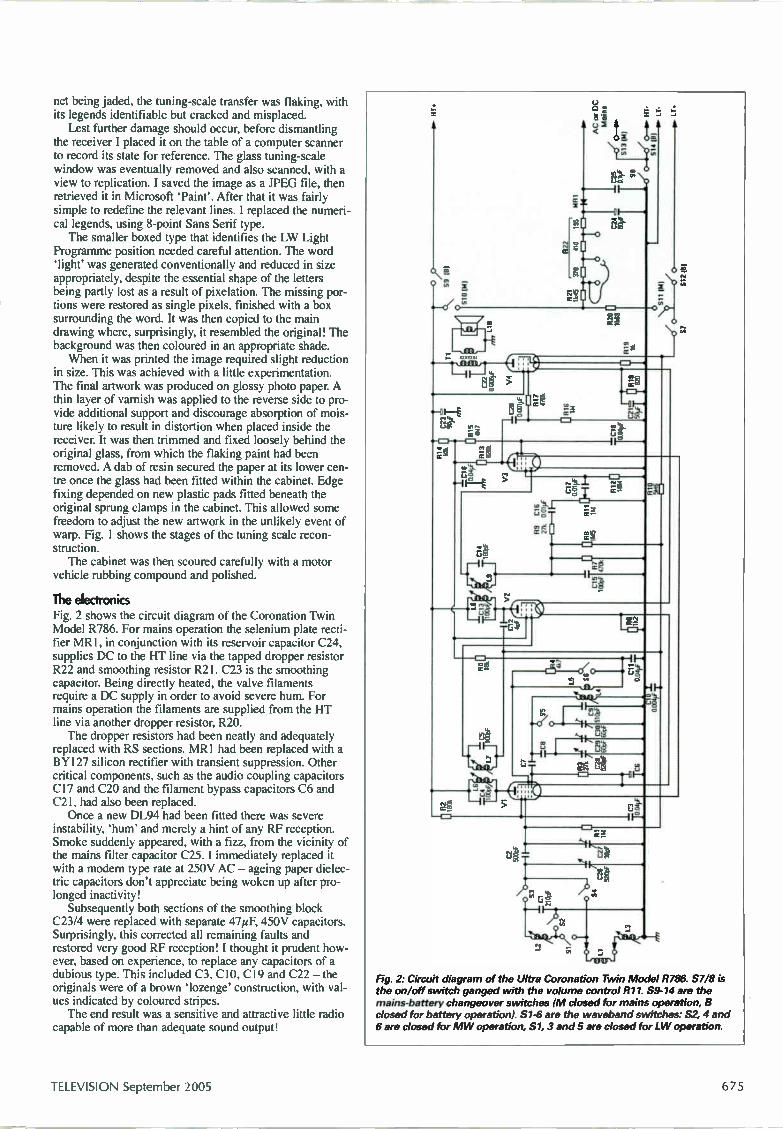
net being jaded, the tuning-scale transfer was flaking, with its legends identifiable but cracked and misplaced. Lest further damage should occur, before dismantling
the receiver I placed it on the table of a computer scanner to record its state for reference. The glass tuning-scale window was eventually removed and also scanned, with a view to replication. I saved the image as a JPEG file, then retrieved it in Microsoft 'Paint'. After that it was fairly simple to redefine the relevant lines. I replaced the numeri-cal legends, using 8-point Sans Serif type. The smaller boxed type that identifies the LW Light
Programme position needed careful attention. The word 'light' was generated conventionally and reduced in size appropriately, despite the essential shape of the letters being partly lost as a result of pixelation. The missing por-tions were restored as single pixels, finished with a box surrounding the word. It was then copied to the main drawing where, surprisingly, it resembled the original! The background was then coloured in an appropriate shade. When it was printed the image required slight reduction
in size. This was achieved with a little experimentation. The final artwork was produced on glossy photo paper. A thin layer of varnish was applied to the reverse side to pro-vide additional support and discourage absorption of mois-ture likely to result in distortion when placed inside the receiver. It was then trimmed and fixed loosely behind the original glass, from which the flaking paint had been removed. A dab of resin secured the paper at its lower cen-tre once the glass had been fitted within the cabinet. Edge fixing depended on new plastic pads fitted beneath the original sprung clamps in the cabinet. This allowed some freedom to adjust the new artwork in the unlikely event of warp. Fig. 1 shows the stages of the tuning scale recon-struction. The cabinet was then scoured carefully with a motor
vehicle rubbing compound and polished.
The electronics Fig. 2 shows the circuit diagram of the Coronation Twin Model R786. For mains operation the selenium plate recti-fier MR I, in conjunction with its reservoir capacitor C24, supplies DC to the HT line via the tapped dropper resistor R22 and smoothing resistor R21. C23 is the smoothing capacitor. Being directly heated, the valve filaments require a DC supply in order to avoid severe hum. For mains operation the filaments are supplied from the HT line via another dropper resistor, R20. The dropper resistors had been neatly and adequately
replaced with RS sections. MR I had been replaced with a BY127 silicon rectifier with transient suppression. Other critical components, such as the audio coupling capacitors C17 and C20 and the filament bypass capacitors C6 and C21, had also been replaced. Once a new DL94 had been fitted there was severe
instability, 'hum' and merely a hint of any RF reception. Smoke suddenly appeared, with a fizz, from the vicinity of the mains filter capacitor C25. I immediately replaced it with a modem type rate at 250V AC — ageing paper dielec-tric capacitors don't appreciate being woken up after pro-longed inactivity! Subsequently both sections of the smoothing block
C23/4 were replaced with separate 47pF, 450V capacitors. Surprisingly, this corrected all remaining faults and restored very good RF reception! I thought it prudent how-ever, based on experience, to replace any capacitors of a dubious type. This included C3, C10, C19 and C22 — the originals were of a brown 'lozenge' construction, with val-ues indicated by coloured stripes. The end result was a sensitive and attractive little radio
capable of more than adequate sound output!
II ; o
tC, /
r..2g œ-
1-L-4
•-t H
sn =.—• .11-•
•-c(0 -
*-1
ó
o
,e 5
Fig. 2: Circuit diagram of the Ultra Coronation Twin Model R786. S7/8 is the on/off switch ganged with the volume control R11. S9-14 are the mains-battery changeover switches (M closed for mains operation, B closed for battery operation). S1-6 are the waveband switches: S2, 4 and 6 are closed for M W operation, S1, 3 and 5 are closed for LW operation.
TELEVISION September 2005
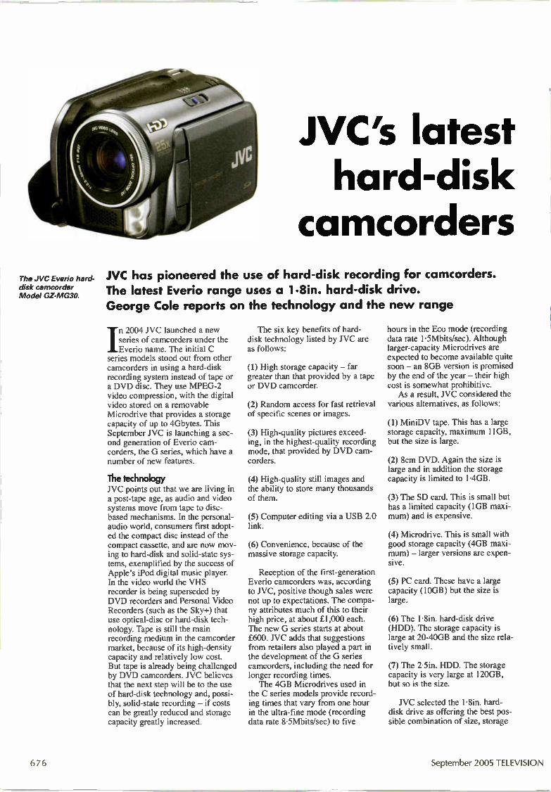
The JVC Everio hard-disk camcorder Model GZ-MG30.
JVC's latest hard-disk camcorders
JVC has pioneered the use of hard-disk recording for camcorders. The latest Everio range uses a 1.8in. hard-disk drive. George Cole reports on the technology and the new range
/n 2004 JVC launched a new series of camcorders under the Everio name. The initial C
series models stood out from other camcorders in using a hard-disk recording system instead of tape or a DVD disc. They use MPEG-2 video compression, with the digital video stored on a removable Microdrive that provides a storage capacity of up to 4Gbytes. This September JVC is launching a sec-ond generation of Everio cam-corders, the G series, which have a number of new features.
The tedmology JVC points out that we are living in a post-tape age, as audio and video systems move from tape to disc-based mechanisms. In the personal-audio world, consumers first adopt-ed the compact disc instead of the compact cassette, and are now mov-ing to hard-disk and solid-state sys-tems, exemplified by the success of Apple's iPod digital music player. In the video world the VHS recorder is being superseded by DVD recorders and Personal Video Recorders (such as the Sky+) that use optical-disc or hard-disk tech-nology. Tape is still the main recording medium in the camcorder market, because of its high-density capacity and relatively low cost. But tape is already being challenged by DVD camcorders. JVC believes that the next step will be to the use of hard-disk technology and, possi-bly, solid-state recording - if costs can be greatly reduced and storage capacity greatly increased.
The six key benefits of hard-disk technology listed by JVC are as follows:
(1) High storage capacity - far greater than that provided by a tape or DVD camcorder.
(2) Random access for fast retrieval of specific scenes or images.
(3) High-quality pictures exceed-ing, in the highest-quality recording mode, that provided by DVD cam-corders.
(4) High-quality still images and the ability to store many thousands of them.
(5) Computer editing via a USB 2.0 link.
(6) Convenience, because of the massive storage capacity.
Reception of the first-generation Everio camcorders was, according to JVC, positive though sales were not up to expectations. The compa-ny attributes much of this to their high price, at about £1,000 each. The new G series starts at about £600. JVC adds that suggestions from retailers also played a part in the development of the G series camcorders, including the need for longer recording times. The 4GB Microdrives used in
the C series models provide record-ing times that vary from one hour in the ultra-fine mode (recording data rate 8-5Mbits/sec) to five
hours in the Eco mode (recording data rate 1-5Mbits/sec). Although larger-capacity Microdrives are expected to become available quite soon - an 8GB version is promised by the end of the year - their high cost is somewhat prohibitive. As a result, JVC considered the
various alternatives, as follows:
(1) MiniDV tape. This has a large storage capacity, maximum 11GB, but the size is large.
(2) 8cm DVD. Again the size is large and in addition the storage capacity is limited to 1-4GB.
(3) The SD card. This is small but has a limited capacity (1GB maxi-mum) and is expensive.
(4) Microdrive. This is small with good storage capacity (4GB maxi-mum) - larger versions are expen-sive.
(5) PC card. These have a large capacity (10GB) but the size is large.
(6) The 1-8in. hard-disk drive (HDD). The storage capacity is large at 20-40GB and the size rela-tively small.
(7) The 2-5in. HDD. The storage capacity is very large at 120GB, but so is the size.
JVC selected the 1.8in. hard-disk drive as offering the best pos-sible combination of size, storage
676 September 2005 TELEVISION
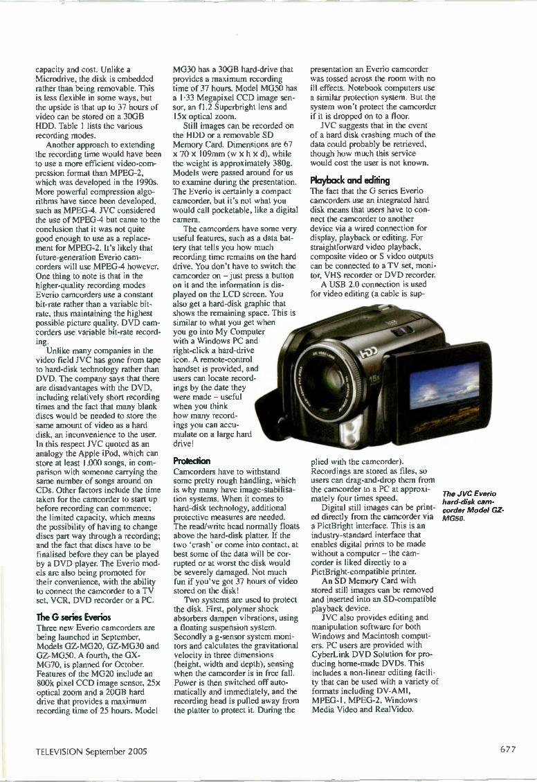
capacity and cost. Unlike a Microdrive, the disk is embedded rather than being removable. This is less flexible in some ways, but the upside is that up to 37 hours of video can be stored on a 30GB HDD. Table 1 lists the various recording modes. Another approach to extending
the recording time would have been to use a more efficient video-com-pression format than MPEG-2, which was developed in the 1990s. More powerful compression algo-rithms have since been developed, such as MPEG-4. NC considered the use of MPEG-4 but came to the conclusion that it was not quite good enough to use as a replace-ment for MPEG-2. It's likely that future-generation Everio cam-corders will use MPEG-4 however. One thing to note is that in the higher-quality recording modes Everio camcorders use a constant bit-rate rather than a variable bit-rate, thus maintaining the highest possible picture quality. DVD cam-corders use variable bit-rate record-ing. Unlike many companies in the
video field JVC has gone from tape to hard-disk technology rather than DVD. The company says that there are disadvantages with the DVD, including relatively short recording times and the fact that many blank discs would be needed to store the same amount of video as a hard disk, an inconvenience to the user. In this respect JVC quoted as an analogy the Apple iPod, which can store at least 1,000 songs, in com-parison with someone carrying the same number of songs around on CDs. Other factors include the time taken for the camcorder to start up before recording can commence; the limited capacity, which means the possibility of having to change discs part way through a recording; and the fact that discs have to be finalised before they can be played by a DVD player. The Everio mod-els are also being promoted for their convenience, with the ability to connect the camcorder to a TV set, VCR, DVD recorder or a PC.
The G series Everios Three new Everio camcorders are being launched in September, Models GZ-MG20, GZ-MG30 and GZ-MG50. A fourth, the GX-MG70, is planned for October. Features of the MG20 include an 800k pixel CCD image sensor, 25x optical zoom and a 20GB hard drive that provides a maximum recording time of 25 hours. Model
MG30 has a 30GB hard-drive that provides a maximum recording time of 37 hours. Model MG50 has a 1.33 Megapixel CCD image sen-sor, an f1.2 Superbright lens and 15x optical zoom. Still images can be recorded on
the HDD or a removable SD Memory Card. Dimensions are 67 X 70 x 109min (w x h x d), while the weight is approximately 380g. Models were passed around for us to examine during the presentation. The Everio is certainly a compact camcorder, but it's not what you would call pocketable, like a digital camera. The camcorders have some very
useful features, such as a data bat-tery that tells you how much recording time remains on the hard drive. You don't have to switch the camcorder on — just press a button on it and the information is dis-played on the LCD screen. You also get a hard-disk graphic that shows the remaining space. This is similar to what you get when you go into My Computer with a Windows PC and right-click a hard-drive icon. A remote-control handset is provided, and users can locate record-ings by the date they were made — useful when you think how many record-ings you can accu-mulate on a large hard drive!
Protection Camcorders have to withstand some pretty rough handling, which is why many have image-stabilisa-tion systems. When it comes to hard-disk technology, additional protective measures are needed. The read/write head normally floats above the hard-disk platter. If the two 'crash' or come into contact, at best some of the data will be cor-rupted or at worst the disk would be severely damaged. Not much fun if you've got 37 hours of video stored on the disk! Two systems are used to protect
the disk. First, polymer shock absorbers dampen vibrations, using a floating suspension system. Secondly a g-sensor system moni-tors and calculates the gravitational velocity in three dimensions (height, width and depth), sensing when the camcorder is in free fall. Power is then switched off auto-matically and immediately, and the recording head is pulled away from the platter to protect it. During the
presentation an Everio camcorder was tossed across the room with no ill effects. Notebook computers use a similar protection system. But the system won't protect the camcorder if it is dropped on to a floor. JVC suggests that in the event
of a hard disk crashing much of the data could probably be retrieved, though how much this service would cost the user is not known.
Playback and editing The fact that the G series Everio camcorders use an integrated hard disk means that users have to con-nect the camcorder to another device via a wired connection for display, playback or editing. For straightforward video playback, composite video or S video outputs can be connected to a TV set, moni-tor, VHS recorder or DVD recorder. A USB 2.0 connection is used
for video editing (a cable is sup-
plied with the camcorder). Recordings are stored as files, so users can drag-and-drop them from the camcorder to a PC at approxi-mately four times speed. Digital still images can be print-
ed directly from the camcorder via a PictBright interface. This is an industry-standard interface that enables digital prints to be made without a computer — the cam-corder is liked directly to a PictBright-compatible printer. An SD Memory Card with
stored still images can be removed and inserted into an SD-compatible playback device. JVC also provides editing and
manipulation software for both Windows and Macintosh comput-ers. PC users are provided with CyberLink DVD Solution for pro-ducing home-made DVDs. This includes a non-linear editing facili-ty that can be used with a variety of formats including DV-AMI, MPEG-1, MPEG-2, Windows Media Video and RealVideo.
The JVC Everio hard-disk cam-corder Model GZ-MG50.
TELEVISION September 2005 677

Table 1: Recording modes and times with Everio G series camcorders Mode MG50/MG30 MG20
Ultra (DVD Movie) 7hr 10min 4hr 50min Fine (DVD) 10hr 40min 7hr 10min Norm (TV) 14hr 10min 9hr 30min Eco (internet) 37hr 30min 25hr
Image
720 x 576, 501 PAL 720 x 576, 50m PAL 720 x 576, 50m PAL 352 x 288, 25p PAL
Video bit rate
8.5Mbits/sec 5-5Mbits/sec 4-2Mbits/sec 1.5Mbits/sec
Audio bit rate
384kbits/sec 384kbits/sec 256kbits/sec 128kbits/sec
The recording times are approximate, with continuous shooting. With NTSC recordings the number of lines is 480, with 60 interlaced fields per second, except in the Eco mode where there are 240 lines with 30 progressively-scanned fields per second. The video bit rate is constant in the Ultra and Fine modes, variable in the Norm and Eco modes.
Fulure plans JVC has lots of plans for its Everio camcorders and hopes that they will become in the video market what the iPod has become in the digital music market. There are plans for MP3 compatibility with future models, so that users could carry thousands of music files around in their camcorders. There's no reason why Everio
could not be used as a portable hard drive, with files transferred from a PC to the Everio and then downloaded on to another comput-er. The stumbling block at present is EU rules which impose addition-al tariffs on video devices that include a video-in connection. This is why the USB link in current Everio models is one-way only, from camcorder to PC.
As mentioned earlier, MPEG-4 compression is likely to be includ-ed in future models. There will also be a high-definition version at some stage. It is also safe to predict that future models will have even larger-capacity hard drives — and shrink in size.
Condusion Everio is an interesting system with some strong features, including the ability to store more than a day's worth of video on a hard drive. At present NC is the only company that's decided to bypass DVD tech-nology and opt for hard-disk technol-ogy instead. More and more con-sumer products are using hard-disk technology, for example personal video recorders and digital music players, so HDD camcorders seem to
be a logical development. But with so many other companies promoting DVD camcorders, NC will have to work hard to promote Everio. NC says that today's hard-disk
drives are robust and reliable, and points out that tape-based cam-corders can tangle the tape while DVD discs can easily be scratched. The company adds that it is more than happy with the number of first-generation Everio camcorders that required some form of service attention. It's too early of course to say
how well these new Everio cam-corders will fare in a very competi-tive market. With a handful of tape-based formats, several DVD for-mats and now hard-disk drive mod-els, camcorder users are certainly not short of choices!
Test Case 513 Despite digital TV, flat-panel screens and microprocessor control, it's mainly the same old circuits and components that give rise to faults. For every digital chip failure there are dozens of breakdowns in conven-tional power supplies, and faults with CRTs and their drive and scanning circuits out-number those associated with flat screens many times over. Indeed with LCD-type displays it's the hot-and-hairy projection lamps, fluorescent backlights and mechani-cal bits such as cooling fans that are most likely to give rise to trouble. Many faults can arise in a perfectly conventional seven-year old TV set fitted with a CRT, but none of them should be difficult to find and fix. This particular one took a little while longer however. The set concerned was a Ferguson Model VS1NB, which is fitted with the Thomson TX91G chassis. It was a rental set that had been collected and brought into the work-shop, the complaint being that the picture was too green. Once it had been hoisted on to Real Technician's bench and powered, the symptom was immediately apparent. Faces looked sickly indeed, while the back-
ground areas, for instance the snowy raster displayed when the aerial was disconnect-ed, seemed to be lacking in green. The lads hooked it up to the workshop test-card gen-erator, whose pattern showed that the green colour bar was excessively bright — to the point where it was smearing and spreading to the right. Near black level however there was a lack of green: dark greys had taken on a magenta colour. Did Real Technician give these symptoms sufficient thought? Not really. If he had, might he have gone straight to the cause? Probably. What he actually did was to tap the neck of the CRT (with no effect) then jump to the conclusion that the RUB output IC was responsible. He found the right type of chip, a TEA5101B, in the component stores and straight away fitted it. Now how did you guess? The fault was still present in exactly the same form! So the IC was not to blame. But the tube could still possibly be defective in some way — not every internal fault reveals its nature with a tap on the glass. Rrs next step therefore was to swap over the drives to the green and red cath-odes (pins 6 and 8). He wanted to see a
green picture, so that he could condemn the set and be rid of it. But this was not to be. The red parts of the test pattern, now con-taining 'green' information, came up bright and flared badly, while lowlights in the dis-play took on a cyan hue. This indicated that the cause of the fault was somewhere in the green-drive circuit, most of which is buried inside the multi-legged IC that had already been replaced. The next test was a comparison between the low-level RUB signals that arrive at the CRT base panel via connector HT01. They proved to be identical with a black-and-white picture. But the waveform that drove the green cathode (the original connections had been restored) of the now exonerated tube was grossly different from the red and blue drives. There followed some desultory testing, with an ohmmeter, of the diodes associated with the green output stage, and also some of the low-value resistors between the IC and the tube. This failed to turn anything up. But the cause of the fault was finally located and rectified. What was it? Turn to page 699 for the solution to this one.
678 September 2005 TELEVISION

Adrian Gardiner describes a simple I2C interface for use with EEPROM chips and some recent servicing problems
Bench Notes I2C interface In my article on workshop equipment (July, page 554) I men-tioned that we routinely keep copies of known good EEPROM programs in our workshop PC. I subseqq,ently received an email from Douglas Russell asking where an IzC interface for use with a PC can be bought. A simple interface can be built from a handful of parts that
you probably have lying around. Fig. I shows the basic circuit we use. Pin 7 of the EEPROM (U1) is shown with a pull-up resistor and a jumper link to connect it to OV. In our interface we simply connect pin 7 to OV, which enables the EEPROM to read/write. When pin 7 is high, the EEPROM is in the read-only condition. Inclusion of the jumper enables us to test this facility. The interface connects to a standard PC parallel port. Construction is straightforward. Almost any npn transistor can
be used in positions Q1 and Q2. II* a BC847 surface-mounted type is used the entire circuit, minus the EEPROM, will fit inside a standard parallel plug shell. The software we use is an excellent program called PonyProg.
It can be used with a wide range of EEPROMs, and provides sav-ing to multiple data formats. Best of all, it's free! The software can be downloaded from http://www.LancOS.com which also contains a lot of useful information and other inter-face circuits.
The Vestel 11AK45 chassis A large number of inexpensive sets, all fitted with the Vestel 11AK45 chassis, have come in recently. They bear various brand names, mainly WC, Hitachi and Bush, and tend to suffer from a common fault, EEPROM failure — perfect for the IzC interface! Model AV28GT1SW is a typical NC example. Hitachi sets include Models C28W460 and C28WF560N. The Bush sets have various model numbers, including RF6683 which is fitted with a super-flat CRT and RF6694 which includes a Freeview DU decoder. A few bytes in the EEPROM seem to fail, corrupting the con-
tents. Symptoms include geometry errors, particularly in the 4:3 mode, returning to standby on certain channels and complete fail-ure to operate. Repair is simply a matter of replacing the EEPROM (type
24C16), loaded with the appropriate software. Although the EEPROMs come preprogrammed when ordered from the manu-facturers, only WC ones seem to work without any further setting up. If you have a copy of the program for each model stored in your PC however setting up is eliminated: you simply load the settings into the new EEPROM before installation. This also enables inexpensive black EEPROMs to be used for out-of-guar-antee sets. Note that although the above models are all fitted with the same chassis it's not possible to interchange the manufactur-ers' data, as this is customised for each model. Another common problem with the 11AK45 chassis is failure
of the STV9379FA field output chip. This is nearly always caused by a corrupt EEPROM. It sends the picture off the bottom of the screen, overloading the field IC. So be sure to replace the EEP-ROM as well as the field output chip, and make sure that you fit one which has the suffix FA. Type STV9379 is not suitable!
An interesting Panasonic A Panasonic TV/VCR combi set, Model TX21GV1, arrived on my bench recently. The complaint was that it reverted to standby intermittently. When the fault occurred it was not possible to turn the set on again using the remote-control unit. You had to switch the set itself off then switch it on again. The on/off switch is of the 'soft' type, which doesn't discon-
nect the mains supply. When it's used to switch the set off, you can't use the remote-control unit to switch the set back on again. But in the fault condition it was still possible to insert or eject a videocassette. It's not easy to dismantle the unit. Once you have taken the
back off, the power supply/deflection PCB has to be removed from the top of the chassis. The next step is to dismantle the screening metalwork, then remove the deck. After that the main PCB can be extracted from the plastic shell. After doing this I gave the PCB a thorough visual inspection.
The on/off switch, which is mounted on this panel, was dry-joint-ed at one side. Resoldering, followed by reassembly, cleared the fault condition.
The Hitachi A7 chassis This chassis used to be straightforward to repair. Normally all we had to do was to attend to dry-joints at the regulators and the field output IC. Just recently however we seem to have been getting all sorts of other nasty faults with these sets. The complaint with a large 32in. set, Model C32W410, was sim-
ply "dead". When I removed the back my heart sank on seeing the shattered remains of what had been a fuse. But it was a nice easy job for a change, as replacement of the fuse and the four mains bridge rectifier diodes brought the set back to life. One of the diodes had gone short-circuit. When this happens I prefer to replace all four diodes — in case the others have been subjected to stress.
PC parallel port DB25 male
o O-
o O-
o o
o o
o o
o o
o o
o o
o o
-O o
-O O-
-O o-
01 BC337
Fig. 1. Simple I2C interface circuit for use with EEPROMs.
TELEVISION September 2005 679
Atmla FAULTS* Reports from
Chris Bowers
Geoff Darby
and
Philip Rosbottom 4,11i111ffltro ffl
We welcome fault reports from readers — payment for each fault is made after publication.
Reports can be sent by post to:
Television Magazine Fault Reports, Nexus Media Communications, Media House, Azalea Drive, Swanley, Kent BR8 8HU
or e-mailed to: t.winford highburybiz.com
Sony IS-D55 This portable unit would stop playing a disc after five minutes. Inspection of the CD mechanism assembly revealed the cause of the trouble — the flexible PC link (358) at the optical pickup. A replacement, part no. 1-660-965-11, restored normal operation. C.B.
Sony TA-VE25 This unit's power button had been pushed in and broken. Inspection inside revealed that the button is part of the plastic front assembly. The complete front panel, part no. A-472-283-7A, had to be replaced to restore normal power-on operation. C.B.
Sony MDS-JE520 This unit would flash error C013 in the display while trying to record. Checks inside revealed that the KMS260A optical pickup was defective. A replacement restored normal operation. Make sure that you connect the flexible PCB before removing the ESD protection jumper. C.B.
Sony STR-DE495 This is an AM/FM receiver. The sound from the amplifiers would cut out after five minutes, but the audio output relays remained in the same state. The cause of the trouble turned out to be the direct function select chip IC201 on side B of the main board. It had not been fitted and sol-dered correctly. All that was required to restore normal operation was to resolder this IC. C.B.
Sonic Link DM20 For various reasons that I won't go into here, other than to say that as usual family were involved, this was another of those 'must-fix' jobs. It's apparently part of a karaoke system, and is described on the rear panel as a 'dual mono amplifier'. I would have said that it's a normal stereo amplifier myself, with volume and balance controls as well as input and push-button selectors for tape, video, radio, CD and phono. The complaint was that the output from the left channel was distorted, and had defied all attempts at repair elsewhere. When I opened it up I was confronted with a large toroidal transformer and a sin-gle fibreglass PCB with a fairly conven-tional-looking amplifier on it. The only slightly worrying thing was a silk-screened legend that said "Audio Kits". Initial tests were inconclusive. The volt-ages in the bad channel were certainly wrong, but not hugely so. Scope checks however showed that only one half of the signal waveform was being amplified, hence the horrendous distortion. Then fol-
lowed the inevitable slip of the meter probe ... One pile of dead transistors later I had nothing at all from the left channel, but still wrong voltages in the early stages. At least nothing was burning however! There's a 5mm LED in each channel back in the driver stages. I've never been very happy about this practice, though it seems to be quite common. Basically it's a way of obtaining a stable reference voltage — the forward voltage drop across the LED. The voltage is very prone to toler-ance spreads however, and the exact char-acteristics of the LED. It's also not partic-ularly stable with temperature change. In the good channel there was about 2V across the LED, which seemed reasonable for a red type. In the bad channel the volt-age reading was 10V, which indicated that the device was open-circuit. I didn't have any 5mm red LEDs, so I fitted a 3mm one. As its efficiency was somewhat better than the original type, it actually lit up. I now had correct voltages and normal-looking drive right up to the output tran-sistors, but still no output from the left channel. This final problem was a leftover from the blow-up I had caused: there were open-circuit 10 resistors by the output transistors. To keep everything balanced, I also replaced the 5mm LED in the right chan-nel, using the same 3mm type I had fitted in the left channel. When the amplifier was reassembled and tested there was remarkably good audio from both chan-nels. G.D.
JVC CA-MXGT91R There were several complaints with this hi-fi unit, including intermittent failure to play CDs, failure of the CD drawers to open and sticking tape decks. When I tried it the mechanical operation of the CD deck was erratic to say the least. Trays would sometimes eject all the way and some-times not at all. At other times the deck seemed to be confused mechanically. A lift cam at the left side of the deck moves the tray loading gear up and down to engage with the requested tray. A mode switch reminiscent of the type used with VCR decks is beneath this lift cam. At the right side of the deck there are six little lever switches that sense the in/out posi-tions of the three trays. I decided that a good initial move would be to clean all these switches. The cam gear was easily removed after teasing off the retaining cut washer. The mode switch was then given a good scrub round, with some switch cleaner/lubricant injected. Vigorous operation of the lever switches,
September 2005 TELEVISION

again with cleaner injected, saw to these. When the deck was refitted it performed faultlessly, apart from poor playability. This was corrected by cleaning the dust off the laser lens. The final problem, with the tape decks, was cured by replacing both main drive belts. It's a very common problem with all the tape-deck variations fitted in dif-ferent JVC models. G.D.
Sony TA-H3600 This amplifier, which is part of a four-piece system, produced normal audio from the headphone socket but not from the speakers. The immediately apparent reason for this was that the output pro-tection relays didn't close. It was easy to get at the terminal pins of the relays, so I applied my scope to each of the four out-put channels (two bass, two mid/high frequency) and found normal-looking audio with no DC offset. Having estab-lished that there was nothing that might potentially damage the speakers, I momentarily shorted across the relay contacts for each channel in turn. This produced normal audio. So I turned attention to the protection sense and drive circuitry, which is centred around IC701, on the power amplifier board. Voltage checks at the pins of the IC were inconclusive. They were not correct compared with the readings shown in the service manual, but except for pin 6 they weren't far enough out to lead to any immediately suspect components. The voltage at pin 6, the drive pin for the relay coils, was completely wrong of course. I began to suspect the IC itself. A hunt through the scrap box produced a board that had one on it, so I set about remov-ing the power amplifier board to get to the IC to replace it. Once the board was out however I spotted telltale signs of electrolyte leakage on the reverse side, close to IC701. The nearest capacitor is C702 (220pF, 10V), and there was a strong smell of fuming electrolyte when it was unsoldered. Curiously however it didn't look as though it had been leak-ing, and ESR and capacitance checks proved that it was OK. I cleaned up around the area and fitted a replacement anyway, but the results were the same. I then replaced the other two electrolytics in the vicinity, C706 and C707, though once again the old ones checked OK. One or two clues suggested that some-one might have been here before me looking for the cause of the fault, and I began to suspect that they had replaced
the leaky capacitor without cleaning up the board. I have to say however that the components and the soldering looked original. This time when I refitted the board the speaker relays closed at the right time and there was normal audio — briefly. After about five seconds both relays dropped back out. Once I had removed the board again I examined the area of the leakage in minute detail. I found that the PCB holes for R705 were blackened around the edges. So I replaced the resis-tor and reflowed every joint in the area. This time when the unit was reassembled and powered the relays closed at the appropriate time and, thankfully, remained closed! G.D.
Pioneer XC-L5 Thanks are due once again to the nice man at Pioneer, without whose sugges-tion the problem would probably have taken a lot longer than it did to solve. Basically, the whole system worked all right except that the output protection relay kept cycling on and off at regular intervals of about three seconds. When it was on there was normal audio from both channels, with no measurable DC offset. The cause of the problem was a defec-tive fan. Apparently the protection cir-cuitry checks the current drawn by the fan to see if it's working. If not, it cycles the relay to warn the user that there's a problem. When I removed the fan it was tight. It was easily freed with a little oil in the bearing, but still wouldn't run. So dam-age had presumably occurred to its wind-ings as a result of it being stalled, despite it being an electronically commutated type. These are normally impedance pro-tected. All was well once a new fan had been fitted. G.D.
Proton AA1150 This large power amplifier would blow the mains fuse on the rear panel because there was a short-circuit across the input. It's a very prestigious item (the amplifi-er, not the fuse) from the late Eighties, with the incredible short-term power capability of 280W at 8Q or 600W at 2Q, but is essentially a 50W RMS stereo amplifier. Anyway back to the fault, eh? Someone had looked at it before. It seems that they may have disconnected the mains wiring to fault-find then con-nected it up wrongly, as one transformer (dual mono) was open-circuit (excess-temperature sensors open-circuit) while the other one was fine. One of the bridge
Z =BIE =IT
Photo 1: The Proton AA1150 power amplifier.
rectifiers was missing from the channel with the faulty transformer. I suspect that it had gone short-circuit and fried the transformer. There are approximately four windings on the secondary side of the transformers, arranged to provide 64-33-0-33-64V. I connected the good transformer to the two channels to see if they would power up and found that they worked fine. Now I have to decide whether it would be worthwhile having the transformer rewound. P.R.
B8g0 3000 receiver This unit looked as if it wasn't powered up: the power switch, with off over it, is on' when it's up, indicating off'. I'm confused already! The cause of the problem — FM drifting through the stations (the unit is varicap-diode tuned) and the left-right channels not working — turned out to be the switchbank. The lever switches are on an interlinked assembly. Either the lubricant had dried up (the unit dates from 1969) or the contacts were corroded. A couple of soaks with WD40 equivalent were required along the whole length. This, followed by constant operation of all the switches for a length of time, eventually got them working again. P.R.
Photo 2: The B&O 3000 receiver.
TELEVISION September 2005 I
Diversifying Oh dear, Elaine is feeling sorry for her-self (the answer is diversify, July)! We all feel a bit despondent about the state of our trade from time to time — but take in a lodger? This time of the year is tradi-tionally quiet. As usual, conditions will improve again. It's a good time to consider your
advertising. When was the last time you did a local leaflet drop? A few spare hours a week can be beneficially used going round the new local housing estates with a fist full of them. What about your skills? If it hasn't
already happened, plasma and LCD sets will soon appear on your bench, also DVD recorders. Are you ready for them? Now is a good time to look into such matters and prepare yourself. It's often thought that we will all become redun-dant as new technology takes over, with manufacturers taking servicing in house. The reality is that manufacturers will be happy for local companies to handle it when — and only when — engineers have updated their skills. Elaine is right on one point.
Diversifying is good, but shelf stacking at the local supermarket? Come on, we're professionals! Diversify into other prod-ucts. As repair engineers, our skills can easily be adapted. Now is a good time of the year to service portable air condition-ers. You may not be able to tackle the refrigeration side, but most faults concern straightforward fan or control failure. As a worst-case scenario you can turn to more mundane repairs such as vacuum cleaners — they are straightforward and moneymakers. Having expanded your service activities and with it your cus-tomer base, you will find that recommen-dations bring in TV sets when they break down. Now stop feeling sorry for yourself
and go make some money! Adrian Gardiner, Dereham, Norfolk.
Send letters to "Television", Nexus Media Communications, Media House, Azalea Drive, Swanley, Kent, BR8 8HU or e-mail [email protected]
using subject heading 'Television Letters'.
Please send plain text messages. Do NOT send attachments. Be sure to type your full
name, address, postcode, telephone and e-mail address (if any).
Your address and telephone number will not be published but your e-mail address will
unless you state otherwise
Vintage audio The technology moves on relentlessly, with the humble cassette having been superseded by the CD, DVD, MP3 and a multitude of other digital formats. I still have many old tapes however. Although I listen to them only rarely, I wouldn't want to be without them. So the other day I attempted to get my
trusty old Aiwa ADF-640, which hadn't been used for about a year, to play an old comedy tape. It was the first proper piece of hi-fi equipment I bought, in the late Eighties, and is an excellent machine, with three heads, dual capstans, fine bias control and Dolby B/C/HX Pro. Not up to the standards of the best Denons and Nakimichis of course, but still capable of superb recordings. One surprising oversight with this
machine is the provision of a headphone jack with no way of controlling the vol-ume, especially as the default volume is so high it can be painful. But it's not too difficult to add a little volume control, adjustable, at the back of the device. When I first had the unit it developed
a temperature-related fault after about six months' use. The logic would become wonky — lights flashing, suddenly going into the record mode etc.— but only when the machine was cold. It was completely reliable once it had warmed up. I returned it for attention but no one could find the cause of this intermittent trouble. I even-tually traced the cause to the oscillator can associated with the microcontroller chip. After careful removal a barely visi-ble solder blob was seen, between the inside of the can and one of the pins. The temperature change must have been enough to produce either a short or not. It has worked flawlessly since then — until the other day, that is. It didn't play that old tape. The drive
belts seem to have stretched and now slip on the motor. Does anyone know if replacements can be obtained and, if so, where? Nick Smith nickesmithnet.ods.org
The Pansonic Euro-4 chassis Test Case 511 (July) related to a faulty widescreen tube in a Panasonic set fitted with the Euro-4 chassis. The tubes are of
Philips manufacture however, at least the ones I've come across have been, with a Panasonic label smartly stuck on top. Carefully peeling the Panasonic label back will reveal this. In our neck of the woods the problem is becoming quite common with two-three year old sets, making an otherwise very reliable set uneconomic to repair. I understand that Philips had a problem with widescreen tubes for a time. While on the subject of the Euro-4 chas-
sis, when resoldering the STRF6654 chop-per chip IC801 ensure that the mains bridge rectifier's reservoir capacitor C811 is fully discharged, as the IC can be damaged if the charge remains — as I've found out. Ray Dunleavy, Raphoe, Ireland.
BS cheques and Leak amplifiers In the August letters page Michael Dranfield mentions Building Society cheques being as good as cash. At one time they were stolen in large quantities, though I don't know if this is still the case. A stolen one is still worthless, no matter how well it's filled in On the subject of Leak amplifiers, I
worked for the company as a lad. If any-one wonders how they got the wires so straight, it was me! I took a three-foot length from a reel, put one end in a vice and gripped the other with a pair of pli-ers. By pulling it steadily the wire would give and stretch a fraction, making it straight as a die. The wiring staff then cut off lengths to suit, adding right-angle bends as required. Brian Gilbert, Hampton, Middlesex.
ESR measurement - and radiograms In his review of the Peak Atlas ESR meter in the June issue Eugene Trundle makes the point that "it would be good to have had ESR readings up to 200, to take into account low-value, high-voltage capacitors such as the 114F and 2.2pF, 100-400V types typically found in the lick-start' circuit in a chopper power supply — they often fail". The Peak Atlas ESR tester's upper
reading is 100. The ESR of a good 1pF. 450V capacitor is typically 150 which, as
682 September 2005 TELEVISION
Eugene points out, is outside the range of the tester. There's a simple solution to this however — the range of the meter can be extended to measure from 10-100Q. The unit's test leads are terminated by
miniature crocodile clips. Eugene made some needle-pointed test probes to con-nect to these clips to make in-situ tests easier. If a 10Q resistor is connected between the clips when we need to test these out-of-range capacitors, the tester will read the parallel combination of the 10Q resistor and the ESR of the capaci-tor. A good 15Q ESR 1pF, 450V capaci-tor then reads 6Q, while a capacitor with an ESR of 50Q will read about 8Q. The upper limit that can be measured is about 100Q, which will give a reading of about 9Q. The formula for two resistors in paral-
lel is R total = (R1 x R2)/(R1 + R2). In our case the effective ESR reading will be (10 x ESR)/(10 + ESR). There's a case for having a resistor of
say 20Q always connected across the test leads. It will have little effect on the read-ings that mainly concerned us, but increases the upper range. In general we are interested in capacitors that normally read less than 1Q, which is marginal for a 47pF capacitor. In the main the presence of a 20Q resistor will have little effect on the usual tests but will log out the higher readings, making them readable. If a 20Q resistor is wired in perma-
nently, a capacitor with an ESR of 1552 will read 8-5Q. This is within the range of the Peak Atlas tester. If the resistor is a 3W wirewound type it will help in the discharge of any charged capacitors. From the specification listed, the abuse voltage tolerated across capacitors over 10 g is 40V. The main reservoir capaci-tor in a TV set is well above this restric-tion when charged. It is of course this very capacitor that does the damage to ESR meters. Remember that ESR is an in-phase
component, and can thus be considered as a resistor. On a different topic, Philip Bea man
writes in the August issue about his first attempt to reduce the volume, to solve a nuisance problem, produced by a radi-ogram (what's a radiogram do I hear some of you say?). He fitted a 10Q potentiometer across the loudspeaker and adjusted it for an acceptable sound level. I think it should be pointed out to younger readers that a valve output stage requires a transformer to match the high impedance at the anode of the valve(s) to
the low impedance of the loudspeaker. A valve output stage is quite happy with a short across the loudspeaker connections — it just damps the primary winding. If there is an open-circuit however the audio output transformer will be quite dis-tressed. The opposite is the case with solid-state audio output stages: an open-circuit will not normally do any damage, but a reduced load will. Alan Willcox, Cardiff.
Colwyn Bay Wireless College As an Old Boy of Colwyn Bay Wireless College I was interested to see the letter and photograph from Alun Rawson-Williams (May, page 442). I feel howev-er that he is mistaken in dating the view of the "wireless service engineers train-ing department" as being in the Thirties. I don't know when Alun first used an
AVO Model 7, but I would be surprised if it was as early as that. I never saw an Avometer until after the war — certainly not at Colwyn Bay, where the equip-ment was famed for its antiquity! When I attended Colwyn Bay in
1941-2 and again in 1948 it was entirely devoted to training marine radio offi-cers. The only test equipment I recall was a voltmeter encased in a small wooden box about 3-4in, square and 2-3in. deep. Three wires with crocodile clips enabled you to measure voltages on two scales — both, if I remember cor-rectly, DC. For many years this was a standard item of equipment, ashore and at sea. The equipment on which we trained
consisted of a Marconi 0.5kW CW/ICW marine transmitter, type 381; a Marconi type 352A marine receiver; an 0-25kW quenched-gap spark transmitter, type 341, a type M automatic alarm; and a type 359 direction finder. To simulate radio signals on which to take bearings a second goniometer, contained in a bis-cuit tin, was mounted above a door. It was generally referred to as "the goniometer over the door" to distinguish it from the one in the DF receiver. Many are the tales told about the
exploits of Colwyn Bay students, far too many (and nefarious) to mention here. But after the war we had an Indian stu-dent called Ram Rao who disappeared at intervals to fly his plane down to the Riviera. It seems that he was a rajah who, unfortunately, died an early death after his return to India. As for the Wireless College itself, it
fell victim to progress, being demolished to make way for a new road. Richard Shaw, Dunstable.
Editorial note: An advertisement in our copy of the Trader Year Book for 1939 shows an AVO Model 7 that certainly looks like the meter in the photograph we reproduced.
Electronic microscope Failing eyesight comes with increasing age, especially for close-up work which, of course, is what our trade needs. Unfortunately, unlike other problems associated with those of us in our fifth decade, they haven't yet come up with a little blue pill to fix the problem! For the past few years we have been
using a small electronic microscope made by C2D attached by USB to the bench PC. This microscope has its own built-in light source and can be freely moved across a PCB to look for track damage, identify components, etc. It has been very useful: the magnification can be altered from 10 to 220 — the lowest magnifica-tion is usually enough — and it beats an illuminated bench magnifier hands down. Last month the bench PC gave up the
ghost. So we attached the microscope to the USB socket of a new laptop comput-er. Unfortunately we then found that the device wouldn't work without the instal-lation CD that came with it several years ago. And here lies our problem. The installation CD has been lost and, while there's an interne site from which to download a copy, the link is dead and emails to the manufacturer have brought no reply. I am therefore wondering whether any
reader has a compatible microscope installation and driver CD? I would be happy either to copy it and return it immediately or perhaps it could be emailed to me for a small fee? The micro-scope, of C2D manufacture, is made of dark-blue plastic with light-blue controls and is described as a microscope/camera. The only identification on the side is a small logo that says "C2D Microscope", with "C2D Camera" at the front and "Made in China" on the base. It seems that it's no longer a current model. Perhaps this is a lesson for the future:
when buying unusual computer peripher-als, the driver CDs should be kept in a very safe place! Robert Philpot, philpoteclara.co.uk
TELEVISION September 2005 683
..aw am arm-
TV FAULT Reports from
Philip Salkeld
Eugene Trundle
Dave Husband
L. Gare
Uel Harte
Charles Ritchie
Richard Lewis
David lngrey
Bob Longhurst and
Glyn Dickinson
We welcome fault reports from readers - payment for each fault is made after publication.
Reports can be sent by post to:
Television Magazine Fault Reports, Nexus Media Communications, Media House, Azalea Drive, Swanley, Kent BR8 8HU
or e-mailed to: [email protected]
FINDING Sharp 28LF92H (11AK45B chassis) These sets are coming in with various fault symptoms, for example failure to come out of standby, blanking out when selecting picture size modes, and intermit-tent cutting out. The faults are caused by the same component, the EPROM IC502. The part no. is V20144774. After fitting the replacement you will have to set up the picture formats. P.S.
Sony KD32DX51U (FE2D chassis) This analogue/digital set came in as a stock set, which means that it had been returned by the customer as faulty. The fault slip indicated that you couldn't record digital stations. When I tried, it recorded the digital sound with the ana-logue picture or, sometimes, a blank raster. Time for the Aspirin or, better still, a phone call to Sony technical. The nice man told me he had heard
from other dealers that the soldering to the surface-mounted transistor Q4608 on board Al was poor. This is the small board next to the main one, so it was easi-ly removed. When I examined it under the magnifier I saw that one of Q4608's pins had no solder at all. To my relief, resol-dering it put matters right. P.S.
Philips 21PT4458/02 (SL01.2E chassis) This set was dead apart from a faint trip-
ping noise. I soon found that the BUT 11APX line output transistor (part no. 9340 5632 1127) was short-circuit. But when a replacement was fitted the line output transformer started to arc. A new transformer (part no. 4822 1401 0669) plus another BUT11APX transistor com-pleted the repair. P.S.
Panasonic TH-42PA20 This plasma set would switch to standby after ten minutes. Use of freezer and the hairdryer brought me to IC551, which is on the top centre panel. Panasonic techni-cal confirmed that this could well be the cause of the trouble. So I ordered and sub-sequently fitted a replacement, part no. C5HABZ200123. A long soak test then confirmed that the set was OK. P.S.
Toshiba 28ZT29B This digital set came in because the pic-ture was breaking up with a green cast. After a few minutes the analogue picture would cut off then appear again. The digi-tal board is in an aluminium screening can to the right of the chassis. At present it's not a repairable item. The procedure is to order a replacement, part no. P237B7656, and return the faulty one to Toshiba. P.S.
Beko 284248WNS (14.2 chassis) The customer complained that the picture had moved over - part of the Sky logo was missing. I found my service remote-control unit to adjust it but, to my horror, it refused to select the service menu. A quick phone call to Beko provided the answer. Use the customer remote-control unit to select the main menu, punch in 9301, then use ± volume to select horizon-tal shift (HSHT) and ± channel to alter the setting. Press 0 to exit and store settings. My thanks to Beko. P.S.
Philips L01.1E chassis Poor EHT regulation is an uncommon fault these days. This set's picture bal-looned with brightness changes, settling down only at very low levels. When checked, the HT reservoir capacitor C2561 (47µF, 160V) was found to have a high ESR. A replacement cured the prob-lem. E.T.
Panasonic TX21M2T/B The sound and picture disappeared inter-mittently, being replaced by a squealing noise. I found dry-joints at three pins of the line driver transformer T351. It was fortunate that the line output transistor had survived in this situation. E.T.
Tatung B chassis The initial problem with this set was field
September 2005 TELEVISION
collapse with R451 overheating. This was cured by replacing the TDA3654 field output chip IC402 and its flyback-boost components C425 and D402. We then had a wide picture with pincushion dis-tortion. TR405 (BC557) in the EW circuit was leaky. E.T.
Toshiba 215238 At switch on the picture was fine. After about five minutes however the field scan progressively decreased, to the point where there was just a bright band about an inch deep across the screen. Replacement of the field timebase chip IC401 didn't help. We eventually found that C412 (47nF), which is connected to pin 7 of the IC, was faulty — leaky in fact. E.T.
Decca D32W4415 This big widescreen set didn't work at all. The user reported that he had noticed a burning smell before the final failure. It had come from the line output trans-former. All was well once we had fitted a replacement, type FBT40824 from SEME. E.T.
Philips 28PW6332/05 (MD1.2E chassis) The problem with this set was intermit-tent line scan collapse. It was caused by a dry and burning soldered joint at the little connection PCB on the scan-coil assem-bly. The EW drive FET Tr7480 had been wrecked as a result. E.T.
Goodmans W322NS (F19 chassis) Mere was no sign of life until the 2A mains fuse had been replaced. We then got sound but no picture. Several dry-joints were found in the line output stage and, in addition, C72 (1/4F, 250V) had dried up, C73 (680nF, 250V) was open-circuit and resistors R82 and R83 (both 15162) were burnt. The effect of C73 being open-circuit was excessive width. E.T.
Samsung CS6226Z When this set was switched on there was severe and continuous sparking: the insu-lation of the line output transformer had broken down. Repair was not sanctioned, because of the high cost of a replacement transformer. It then emerged that this set had been bought in Saudi Arabia. E.T.
Toshiba 15V118 It's the first time I've seen one of these portables, so I was thankful that it is included on Toshiba's service manual CD SMCD005. The problem was that the HT would start to decrease after about ten minutes, with the result that any increase
in beam current reduced the width and caused field foldover. Much use of freezer and the hairdryer
pinpointed Q502 (KRC111SRTK), a sur-face-mounted transistor that's located close to the optocoupler. It seems to be used to shut down the power supply in an excess-current condition. To my surprise it read open-circuit when removed. D.H.
Amstrad TVR1 The 1'V sound was very distorted but it was OK when playing videotapes. Off-air sound is routed via Q2301. Checks here revealed that the base bias was only 0.03V instead of 5V. The cause was R2304 (1001d2), which was open-circuit. L.G.
B8L0 L2800 (type 3726) When this set was switched out of stand-by there was a sound like very rough line drive, then it reverted to standby. The lower EW modulator diode D34 was short-circuit and the line output trans-former was faulty. Once these items had been replaced the set produced a picture with reduced width and heat came from diode D37 (BA159) which was leaky. All was well once this diode had been replaced. L.G.
Minot° T140I (PT92 chassis) This set had been bought from Tesco. It was dead because the start-up resistor RPO6 (3.9MQ) was open-circuit. L.G.
Amstrad STV20 The picture was very poor with terrestrial TV reception but satellite reception was fine. Scope checks around the LA7952 video switching chip IC501 showed that the output waveform at pin 1 looked very much worse than the terrestrial TV that went in at pin 4. In fact C503 (470/4F, 16V) was short-circuit. L.G.
Daewoo GB14C3BL This fluorescent-purple coloured 14in. portable was dead. Fortunately power-supply output voltages are marked on the PCB. They were all present though the 12V supply was low at 9.8V. As there was HT at the collector of the line output transistor I decided to check the DC con-ditions at the line driver transistor. There was no collector voltage because the driv-er transformer was open-circuit. A replacement, from a scrap CP380 chassis, cured the fault. U.H.
Philips 28PW6006/05 (L01.1E chassis) The reported fault was dead with a click-ing sound. Expecting to find a short-cir-cuit line output transistor, I was surprised
to discover that the relay, circuit refer-ence 1400, used to switch for panorama viewing was clattering continuously. A replacement line output transformer restored normal operation. U.H.
Daewoo DWX-28W5GB (CP885 chassis) This dead set had been elsewhere. The mains fuse was missing and the STR-F6654 chopper chip 1801 had either been resoldered or replaced. Whatever had been done there was a short between pin 4 (VCC) and chassis. After removing the IC I decided to check other components and found that R855 (3.3MQ) and R804 (0.2252) were both open-circuit. As a pre-caution I decided to replace the optocou-pler chip 1804 as well. Once the replace-ments had been fitted the set produced an excellent picture. U.H.
Matsui 2109NS The set was dead. I am not familiar with this chassis but soon found that the chop-per FET drive was not being biased on. The cause was the 2.2MQ start-up resis-tor RP506 which was open-circuit. U.H.
Grundig ST55-934 (CUC2121 chassis) The fault symptom was line collapse. The burning smell that was present quickly took me to C53006 (330nF) and R30012 (101(Q) which were both open-circuit. Replacements restored normal operation. Note that the value of these components can vary depending on the type of tube fitted. U.H.
LG KI-14V38 This set was dead with the mains fuse blown. The usual culprit, the degaussing posistor, was this time intact. Before con-demning the expensive STR-S6707 chop-per chip IC1801 check the blue disc-type capacitor C807 (1nF, lkV) which may be leaky or short-circuit. U.H.
Philips 25PT4103/07 (L6.2 chassis) The fault symptoms with this set were field cramping and flyback lines at the top of the picture. Once C2904 (100/4F, 25V) and C2905 (220/4F, 25V) had been replaced the field scanning was correct. C.R.
Bush WS6680SIL (Beko 14.2 chassis) The job card said "no picture". I had the set on soak test for several days but the fault never put in an appearance. When I phoned the customer he told me that the fault was intermittent and that when it occurred the picture slowly faded off and
TELEVISION September 2005 685

on, with the sound remaining. This imme-diately suggested a problem with the CRT's heater supply, which proved to be the case. The ballast resistor (value depends on CRT type and size) was dry-jointed. C.R.
Roadstar CTV5501 This 5.5in. colour portable had a very defocused picture. The old glue that supports the base socket on the neck of the CRT had become conductive. Cleaning it off cleared the fault. But the base socket then didn't fit
tightly against the CRT neck, and there was the possibility that with normal han-dling it might fall off. I used a few drops of hot-melt glue to support it and avoid-ed applying this to the high-voltage pins, i.e. focus and A 1/G2. C.R.
Muruyama PHL147 (Philips CTT-Ff AA chassis) This set appeared to be dead. I repair a lot of these sets, so I expected to find that the blue disc-type ceramic capacitor C2524 (1F, 1 kV) in the power supply was faulty or that the line output trans-former was faulty with shorted turns. But not on this occasion. R3444 (5.6k0) in the HT feed to the line driver stage was open-circuit. A replacement restored nor-mal operation. C.R.
Nokia 6355UKSFN (Stereo Plus chassis) The 52000AF line output transistor VK50 in this set was short-circuit. I removed it and connected a 60W bulb between pin 1 of the line output transformer and chassis. This proved that the HT was correct, at 150V. Before fitting a replacement tran-sistor I carried out a visual inspection and found a dry-joint at capacitor CK51 in the EW diode modulator circuit. This had probably been the reason for VK50's failure. As a precaution I also replaced the BC337-25 line driver transistor VK22 and CK22 (2-2/4F, 100V) in its collector damping network. This brought the set back to life, with a surprisingly good picture for its age. C.R.
Daewoo GB21C6NTS This set was tripping with the front LED flashing. An in-circuit test suggested that the line output transistor was short-cir-cuit, but it proved to be OK when tested out-of-circuit. The faulty component wasn't far away — D403, type BY228. C.R.
Schneider STV1500 This elderly set had no sound output. The
usual components that cause this are Q602 (2SD468) and Q608 (25B562) in the audio output stage. But both were OK this time. Further checks revealed that the 16Q, 1W speaker was open-cir-cuit. Luckily I found a replacement in my pile of salvaged speakers. Transistor type BD131 is a suitable
replacement for the 2SD468 and type BD132 for the 25B562. C.R.
Hitachi AE7 chassis For no sound, picture OK, the sound can obtained by restoring the set to the facto-ry mode. To enter this mode select menu, hold and the vol+ and vol— buttons together and press for about five seconds. Install, service and exit then appear. Select the factory mode: this will reset the EPROM to the default settings. Then select exit. You may find that you need to adjust the picture settings, but you would have to do this anyway if you replaced the EPROM. I've done this many times. No prob-
lems so far. R.L.
Goodmans GTV69W3VPL (Vestel 11AK37 chassis) We've had three of these sets in recent weeks with an EW fault. In each case the cause was C622 (12nF, 630V) in the EW diode modulator circuit. D.I.
Mitsubishi CT29A6STX The complaint with this set was bowing at the top and bottom of the picture. It was not noticed when a full-screen pic-ture was being transmitted. None of the controls on the NS panel had any effect. Correct operation was restored by replacing Q4009 (25A950). D.I.
Philips 28PW6816/05 The fault symptom with this set was a line-tearing effect. The sub-PCB on which the infamous Painter chip is mounted is also the home of a TDA9171T chip, IC7405. This was the cause of the trouble. B.L.
Goodmans TVC201T This TV/VCR combi unit produced a very bright raster with flyback lines. Checks on the CRT base PCB revealed that R916 was open-circuit. Its coloured bands were scorched beyond recogni-tion. With no circuit diagram, and no technical assistance being available from Comet, I decided to measure from both ends of the resistor to the centre point in an attempt to establish its value. 100Q seemed likely. But the replacement resistor went up in a puff of smoke, the
cause being the TDA6107G RGB output chip IC901. The Alba version, obtained from CHS, is an upgraded TDA6108VF which cured the fault. I assume that a CRT flashover had seen off the original IC and resistor. B.L.
Matsui TVR2080T This set produced a very dark picture. A check on the first anode voltage showed that it was low at 250V, and couldn't be increased by adjustment of the control on the LOPT. The cause was on the CRT base PCB, where C819 was reducing the voltage when under load. B.L.
Sony KV14M1U (BE4 chassis) This set was dead and I soon found that the 2SC2055N line output transistor Q802 was short-circuit. I removed it to measure the HT voltage and found that this was missing. Checks in the power supply revealed that R615 (0.470 fusible, CHS code 25005RA) in the feed to the STR-S5706 chopper chip IC601 was open-circuit. After replacing R615 and IC601 the HT was present at about 125V. Not knowing in what order these components had failed, I decided to remove and check the line output trans-former. It turned out to be OK and, once Q802 had been replaced, the set powered up and was fine. B.L.
Goodmans W282NS (F19 16:9 chassis) There was slightly reduced width with a little EW distortion. As usual with these symptoms, capacitor inspection paid off — C68 (15nF, 1-6kV) was looking very sorry for itself. But the fault was still present after fitting a replacement! The EW driver FET TR12 had also been damaged. A similar one is used in the 11 AK19 chassis. G.D.
Sony KV28LS6OU (AE6B chassis) This set was tripping with three flashes from the LED. It didn't take long to establish that the 2SC5696 line output transistor Q8804 was short-circuit. I replaced it, along with the Slovenian-made LOPT T8800, only to be rewarded with four-flash tripping! This was not too serious: the two fusible resistors in the HT feed, R8895 and R8896 (both 0-470, 1/16W fusible), had failed. Replacement of these produced a terri-
ble picture — the digital noise reduction was on! Fortunately this set is much easier to
work on than most modern Sonys. G.D.
686 September 2005 TELEVISION

DVD Fault reports from Amrith Ramjewan
Chris Bowers and
Geoff Darby
We welcome fault reports from readers - payment for each fault is made after publication.
Reports can be sent by post to:
Television Magazine Fault Reports, Nexus Media Communications, Media House, Azalea Drive, Swanley, Kent BR88HU
or e-mailed to: t [email protected]
Samsung DVD909K This DVD player's standby light came on but when the standby button was pressed it went off briefly then came on again. After replacing the three 33014F capacitors on the secondary side of the power supply everything worked normally. A.R.
Wharfedale DVD6OST There was no sound from this DVD play-er. Checks around the microcontroller chip showed that there was no voltage at the SCL and SDA output pins 38 and 39, which are connected to the volume con-trol IC. In fact the resistance to chassis at these pins was SQ. A new microcontroller chip restored normal operation. A.R.
Sony HCD-S800 There was an RDS display problem with this unit: when the RDS information changed, parts of the previous display remained visible. Oscilloscope and meter checks around the microcontroller chip showed that the cause was IC901 (type uPD703033A YGF-M27). I discovered from Sony technical that a modification, using the 8500 IC kit (V113) assembly, part no. X-4954-876-1, is required. Once this had been installed the RDS display was normal. C.B.
Sony HCD-S800 There was an intermittent fall in the out-put from the front left-hand column speaker. Checks inside the unit revealed a dry-joint at L401 on side B of the amplifi-er PCB. A quick resolder here cured the problem. C.B.
Sony HCD-SB100 This unit would power up then, after ten minutes, suddenly power off. The fault was caused by IC901, part no. 9-719-947-
79. When a replacement is fitted a zener diode, ZD955, should be added across C907. Connect its cathode to the positive side of the capacitor and its anode to the negative side. The part no. is 9-719-947-79. C.B.
Sony HCD-SC8 There were playback problems with spe-cific DVD discs - the picture would sometimes freeze or start to skip. There's a firmware upgrade to deal with this prob-lem. Installing it cleared the problem. C.B.
Samsung HT-DB120 This home cinema unit provided a useful object lesson in not allowing complacency to override proper fault finding. It came in with a request for urgent surgery to remove its owner's rental disc while the delivery person waited. The disc was easi-ly removed, and the chap went on his way. While it was in bits on the bench I thought I might as well dive in and see if I could fix it. When it was switched on it almost
immediately went into a display-indicated 'protection' mode. In such cases one gen-erally suspects the output stages. All six in this model consist of discrete compo-nents rather than ICs however - in general I've found that these are more robust and proof against customer-amuse than IC types. A good examination of the main PCB
revealed a slight bulge at the top of C30 (47014F, 16V). It's not particularly close to the power supply (linear) or anything hot, but I checked it and the nearby C31 with my trusty ESR meter. With both capacitors the digital display showed a nice low reading of just under 0-251 The table on the meter's front panel suggested that it was a reasonable reading for a capacitor of this value. So I moved on and spent some time poking around in the out-put stages, to no avail. Eventually I decided to replace the
slightly bulged capacitor. When I switched the unit on again I was surprised to see that 'hello' came up on the display followed by a full normal power up. I rechecked the replaced capacitor, which still read good. Then it dawned on me. Checking again, but this time with an AVO meter, I found that the capacitor had an 0.19Q DC short - not ESR goodness! G.D.
Sony DVP-N5355 A nice easy one for a change. The reason for this player's failure to read discs was that one of the flexiprints from the deck was displaced in its connector, at the board end. Once it had been reinserted correctly the unit worked normally. G.D.
September 2005 TELEVISION 687

TELEVISION BOOKS AND HOME ELECTRONICS REPAIR
The Television Book Service offers access to our team of specialist publishing experts. We can order any book or CD-ROM currently in print from War And Peace to the Nevvnes Guide to Television and Video Technology. All books are delivered free of charge within the UK unless otherwise stated. Contact us at the numbers below: Telephone: 01737 812727 or 01737 812676 Fax: 01737 813526 Email: [email protected]
DVD PLAYERS AND DRIVES K F Ibrahim (College of North West London)
This text is based on hands-on experience and acts as a guide to DVD technology and its application, with a special focus on design issues. The principles of the subject ore introduced from the basics, and DVD applications are illustrated by genuine technical information.
Aug 2003 A 256 pages • Glossary A Index PB A Published in UK
Code 0 7çoi, ç7 lA 7 £24.99
NEWNES GUIDE TO TELEVISION & VIDEO TECHNOLOGY Eugene Trundle
An exploration of television and video technology. It covers the fundamentals of digital television (satellite, cable and terrestrial) and digital video, as well as providing a grounding in analogue systems.
3rd edition A Feb 2001 • 432 pages • Index PB A Published in UK
Corm ü 7506 18i 0 1 £17.99
1 RSGB RADIO & ELECTRONICS COOKBOOK Rodio Society of Great Britain
Only o basic knowledge of electronics is assumed for this collection of electronics projects, and it is ideal for all electronics and DIY enthusiasts and experimenters. Designed by the RSG8, the UK radio amateurs federation, the projects are clearly explained step by step.
Nov 2000 A 336 pages • P8 • Illustrations Published in UK
£17.99
CLOSED CIRCUIT TELEVISION: CCTV INSTALLATION, MAINTENANCE AND OPERATION Joe Cieszynski
CCTV surveillance is one of the fastest growing areas in the security industry, and this is a thorough guide to the technical side of UP/ — including installation, maintenance, video recording, cameras and monitors. The second edition is fully dual-standard for PAL and NTSC systems.
2nd edition • Sept 2003 • 256 pages Glossary • Index A PB A Published in UK
£24.99
ELECTRONIC CLASSICS: COLLECTING, RESTORATION AND REPAIR Andrew Emmerson
This text encompasses all aspects of buying, collecting, restoring, repairing, sourcing parts, professional services, clubs and societies. The first part covers technical aspects of restoration and details where components can be found; the second presents useful information for collectors.
Aug 1998 • 256 pages A Index 10 halftones A 50 line illustrations • PB Published M UK
fo, £21.99
INTRODUCTION TO DIGITAL SYSTEMS John Crisp
This self-study text introduces digital electronics from first principles, before going on to cover all the main areas of knowledge and expertise. It covers the practicalities of designing and building circuits, including fault-finding and the use of test equipment.
Feb 2000 A 302 pages A Glossary A Index PB A Published in UK
£18.99
DICTIONARY OF VIDEO AND TELEVISION TECHNOLOGY Jack Tsatsoulin
This work provides comprehensive and contemporary information on the essential concepts and terms in video and television, including (overage of test and measurement procedures. The al accompanying the text includes an electronic version of the book.
Sept 2002 • 365 pages & (D-Rom
Published in UK
£29.99
NEWNES DICTIONARY OF ELECTRONICS SW Amos; RS Amos
Aimed at engineers, technicians and students working in the field of electronics, this dictionary provides clear and concise definitions, including TV, radio ond computing terms, with illustrations and circuit diagrams.
4th edition • Mar 2002 A 394 pages 100 illustrations • 111 A Published in UK
£12.99
NEWNES GUIDE TO DIGITAL TV Richard Brice
Covering all aspects of digital television, this text encompasses the electronics of the equipment, dato compression, television production, servicing and the different transition methods - terrestrial satellite and cable. The test has been updated with developments since the 2000 edition
2nd edition A Oct 2002 A 304 pages A Index 45 illustrations A 15 photographs A HS Published in UK
Code 11 1506 5/21 T £24.99
PRACTICAL ELECTRONIC FAULT FINDING AND TROUBLESHOOTING Robin Pain (Design Engineer, Cotag International Ltd)
A text using simple circuit examples to illustrate principles and concepts fundamental to the process of analog and digital fault finding. It aims to help the reader tackle any job, from fixing a PI to improving the sound of a hi-fi. A digital multimeter and oscilloscope are needed for these ¡obs.
Apr 1996 A 284 pages • Index 50 line illustrations A PB A Published in UK
Lou O are 2161 2 £21.99
PRACTICAL ELECTRONICS HANDBOOK Ian Sinclair
A collection of all the key data, facts, practical guidance and circuit design basics needed by a spectrum of students, electronics enthusiasts, technicians and circuit designers. It provides explanations and practical guidance, and includes new sections on SHF techniques and intruder alarms.
Practical Electronic Handbook
5th edition • Feb 2000 A 571 pages Illustrations • P8 • Published in UK
f(ideúipà4A)i £16.99
REFERENCE DATA FOR ENGINEERS: RADIO, ELECTRONICS, COMPUTERS AND COMMUNICATIONS Mac E Van Valkenburg; Edited by Wendy Middleton
Written by professionals for professionals, this is a complete reference for engineers. As well as addressing radio technology data, it covers digital electronics, computers ond communications.
9th edition A Aug 2001 1568 pages & CD-Rom A 1385 line illustrations 118A Published in UK
Code 0 7 - £90.00
SERVICE ENGINEER'S POCKET BOOK Lewis & Sinclair
This title aims to provide the service engineer with all the necessary information to carry out work on domestic electronics equipment. The coverage ranges from satellite reception to NUM. Both analogue and digital equipment are covered, and there are chapters on common problems.
Jan 1998 A 238 pages A HB
£14.99
SERVICING TV, SATELLITE & VIDEO EQUIPMENT Eugene Trundle
A practical hands-on guide for service engineers, installation technicians and servicing students, this text emphasises the practical business of fault diagnosis and repair of TV, satellite and video equipment.
Rilla i n han "T v l
MG M;
a
Revised 2nd edition • Nov 2001 A 336 pages ¡ Symptom index • PB A Published in UK
£21.99

TELEVISION MICROPROCESSOR IC DATA FILES 1 Edwards
Microprocessor ICs are the most complicated part of TV equipment and present special problems to the engineer. This text covers the most popular microprocessor ICs. Each device is presented graphically with the relevant data information given against each pin.
Mar 1997 • 240 pages • 200 line drawings
PSA Published in UK Cori, £19.99
TELEVISION IC DATA FILES 1 Edwards
A compendium of data on all the most common integrated circuits used in televisions. Each device is illustrated with a pin-out diagram, and all the measurements and signal data in the book were taken under actual working conditions. This second edition contains over 70 new ICs.
Television IC Data Files
2nd edition A fan 2000 A 245 pages
PB • Published in UK
L_ £18.99
TV FAULT-FINDING GUIDE Edited by Put« Marlow
A distillation of the most-used fault reports from I I years of Television magazine. Arranged by make and model, it features over 200 reports on over 300 models of television, including diagnosis and repair advice.
Mar 2000 A 387 pages • Illustrations
PB • Published in UK
f 20.99
VALVE AMPLIFIERS Morgan Jones
The author's straightforward approach, using as little maths as possible, should be of use to those with only a limited knowledge of the field as well as being the standard reference for experts in valve audio. Design principles and construction techniques ore also provided.
Valve Amplifier:
3rd edition A Aug 2003 • 624 pages A Index PB • Published in UK
£29.99
VCR FAULT-FINDING GUIDE Edited by Peter Marlow
A distillation of the most used fault reports from 11 years of Television magazine. Arranged by make and model, it features over 2000 reports on over 200 models of VCR, including diagnosis and repair advice.
Mar 2000 • 447 pages • Illustrations • PB Published in UK
(ode 0-1506-4634-9 £20.99
VCR IC DATA FILES 1 Edwards
This text aims to provide the workshop technician and the field engineer with a convenient method of fault-finding without the need to consult workshop manuals. The most popular ICs used in video recorders are covered. Each device is presented graphically with data given against each pin.
Jul 1998 • 448 pages • 200 line illustrations PB à Published in UK
Code 01506-3993-8 f 20.99
VIDEO AND CAMCORDER SERVICING AND TECHNOLOGY Steve Beeching
A comprehensive guide to domestic VCR technology and repair techniques. This edition brings the information fully-up-to-date, with expanded coverage of camcorders, sections on DOD equipment and the latest VCR technology.
5th edition A Apr 2001 A 323 pages Illustrations • PB • Published in UK
Code b /506-3039 f 20.99
VIDEO DEMYSTIFIED Keith Jack
This edition has been updated to include information on digital television, datacosting, interactive video, digital camcorders and VCRs, and video interfacing. Coverage is international, including European, Asian and North/South American video standards, methods and techniques.
3rd edition • Jul 2001 A 784 pages 8. CD-Rom References A Glossary A Index A PB Published in UK
Code 1-878107-56-6 £50.00
THE DIGITAL SATELLITE TV HANDBOOK Mark E Long
A handbook and CD-ROM pack on digital satellite television. It provides on overview of all the digital TV plotforms in use world-wide. It includes satellite coverage mops and transmission parameters that readers will need to receive digital TV service. from any location in the world.
Ile heal SiltoOt 11 Isoltoot
Sept 1999 A 207 pages 8, CD-Rom • PB
(ode au ü- hut) £41.99
NEWNES GUIDE TO RADIO AND COMMUNICATIONS TECHNOLOGY tan Poole
This is a guide to the technology and applications of modern radio and communications equipment. The author's approach provides a useful foundation for college students and technicians seeking an update on the latest technology.
Jul 2003 A 352 pages • Index A PI Published in UK
Code U/Ubjo L j £16.99
VALVE RADIO AUDIO
REPAIR HANDBOOK Charles Miller
A practical manual for collectors, dealers and service engineers of valve audio and radio equipment. This edition includes new material on restoration and valve amplifiers.
RADIO& n, REP» HANI )
2nd edition • Apr 2000 • 280 pages • I 0 halftones • 50 line illustrations • PB Published in UK
(ode 0 7506 3995 ,1 £20.99
NEWNES TV & VIDEO ENGINEER'S POCKET BOOK Eugene Trundle
This updated text provides a pocket tool for service engineers. It presents a ronge of essential information in a compact form, covering television reception, satellite and cable television, video recorders, colour camera technology, teletext and fault-finding.
étlgto inen •
3rd edition A Oct 1999 A 512 pages A HR
Code BUT 0-7506-4194-0 £17.99
TELEVISION ORDER FORM
Please order or search the following:
Code Description Qty
POSTAGE & PACKING FREE IN THE UK* TOTAL
Name Daytime Tel
Price
Address
Postcode
I enclose a cheque/postal order value payable to 'Boffin Books Ltd'
Please debit my Access/Visa/Switch/Delta card Issue number (Switch only)
Card Number
Signed
'Postage charges outside the UK available upon request or email : salesteomgboffinbooks.demon.co.uk
eon IC Boffin Books Ltd, 24 Walton Street, Walton-on-the-Hill, Todworth, Surrey KT20 7RT, UK
Expiry Date ._
If you are ordering hy creel cord need further information or would like lo use our smirch forams, col
01737 812727 Fax 01737 813526 The order/helpline is open from gam to 5pm, or leave your order on our out oThours answerline or email us at
solesream à,boffmbooks demon co uk When placing orders please quote • Nome • Address (home & delivery) • Daytime telephone number • Debut/Credit card number
• Expiry dare • Details of order. Please note hot prices may change, but are correct al time of going to press

Extended Reports Reports on complex or tricky TV fault conditions are sometimes too long for inclusion in our basic fault-finding section. We've put a few of them together in this extended
fault report feature
Reports from
Arthur Jackson
Steve Hague
Charles Ritchie
Glyn Dickinson and
Les Mainstone
We welcome fault reports from readers — payment for each fault is made after publication.
Reports can be sent by post to:
Television Magazine Fault Reports, Nexus Media Communications, Media House, Azalea Drive, Swanley, Kent BR8 8HU
or e-mailed to: [email protected]
Fault Samsung SP42 W4HBX/XEU The complaint with this 42in. rear-projec-tion set was poor picture quality — the effect was very unusual, to some extent resembling the symptoms of a soft tube in a standard TV set. The picture was gener-ally dull, and parts of the images in it had a large halo effect around them. All three primary colours were present, but closer examination revealed that the halo effect was prominent on green images. As a check I decided to run each tube
separately, by sliding off the base sockets. With the red and blue tubes run individual-ly clear and focused red and blue pictures were displayed. But when the green tube only was driven there was a totally unfo-cused green display. As the cables were long enough I tried connecting the blue base to the green tube, which now pro-duced a clear and focused green picture. So at least all three tubes were good. Close examination of the green base
socket revealed corrosion on the focus pin and evidence of liquid around the socket. Cleaning off any liquid and fitting a new tube-base socket restored perfect pictures. I was very concerned that the source of
the liquid might have been leakage of the coolant fluid from the face of the tube, as on a couple of occasions I've seen this destroy a set when the coolant ran into the chassis. Fortunately a close examination here and a long soak test proved that all was well. The very unusual picture was obviously
because the red and blue tubes had perfect focus while the green tube had none. These symptoms could be displayed only by a rear-projection model. A.J.
Sanyo CBP2876A (EDO-28 chassis) This elderly set had been in use for about twelve years on a high shelf in a bar. Its first fault had now developed: the com-
plaint was about switching to standby quite frequently. When I removed the rear cover, the amount of nicotine, dust and cobwebs had to be seen to be believed, not to men-tion the smell. Every ventilation slot was clogged. So a thorough clean out was required before any checks could be made. After that the set came on with sound
and a picture when tried, but switched back to standby after about twenty sec-onds. Movement of the main PCB almost anywhere enabled the set to restart and run however, so a dry-joint somewhere seemed the likely cause. The main reason for the trouble was
very dry connections at all pins of regulator chip IC850, which is on the secondary side of the power supply. It provides the 5V standby and 12V outputs. There were dry-joints elsewhere, particularly at the scan-coil connecting socket on the PCB. Once these areas had been resoldered the set came on and ran permanently, but a couple of other problems that hadn't been men-tioned were now evident. These were tele-text lines visible down the screen (slow field flyback) and poor EW geometry. The field output stage problem was
caused by the flyback boost capacitor C703 (10014F, 35V), which was open-cir-cuit and leaking badly. The EW problem was also caused by an open-circuit capaci-tor, in this case C750 (2.2µF, 50V) in the EW amplifier stage. Replacement of these two capacitors cleared the final problems and, once a thick brown scum (probably caused by years of passive smoking) had been cleaned off the screen, the picture was perfect. In fact I'm surprised I didn't get a complaint about it now being too bright! A.J.
Panasonic TX28DK2 (Euro-4 chassis) The complaint with this modern widescreen set was no sound. When I switched it on however I thought that the fault report must be wrong: there was a very loud squeal from the power supply, and I suspected an overload in the line out-put stage. But just as I went to switch the set off a picture appeared, with the squeal still present. I don't have the manual for this model,
but found enough information in the manu-al for another model fitted with the Euro-4 chassis. This showed a module known as the C board. It contains the output devices for the centre and surround (left plus right) loudspeakers. When plug Cl on this PCB was removed, disabling the 300V DC input to it, the overload cleared and the set pro-duced a picture plus very good sound from the internal loudspeakers. The cause of the problem was found to
be two short-circuit diodes, D2714 and D2715 (type 1SS133T-77), that are associ-
September 2005 TELEVISION
ated with the TDA2030AV centre loud-speaker output chip IC2703. They are connected across the ±18V supplies, for protection. There were no other problems with the set. We advised the customer to check the cable runs and connections to all the external loudspeakers: he subse-quently confirmed that there had been a problem in this area. Ai.
Hitachi C28 W440N (11AK33 chassis) "[here was extensive damage to the switch-mode power supply in this set. The most obvious item was the chopper FET Q102 (STP8NC7OZPF) which had blown apart. The two BA159 diodes D140 and D141, which are in series with its source, were short-circuit, and the lkià surface-mounted resistor R155 which is between its gate and source was open-circuit. I decided to replace the MC44608 chopper control chip IC106 as well, for good mea-sure. On the secondary side of the circuit I found that the MUR460 HT rectifier D121 was short-circuit and R144 (1Q, 2W) in the excess-current trip was open-circuit. Once replacements had been fitted the
power supply still wouldn't start up. Further investigation revealed two faulty components in the power-factor correction circuit between the mains bridge rectifier and the chopper transformer. The main components here are another FET, Q100 (MTP6N60E), and its driver chip IC107 (MC33260). This IC has an LT supply at pin 8 and a voltage-sensing input at pin I. R112 (1.5MQ) in the feed to pin lwas open-circuit while D106 (1N4148), which provides the LT supply at pin 8, was short-circuit. All was well once these two items had been replaced, but I'd love to know which of those nine faulty compo-nents was the cause of the mayhem. S.11.
SEG CT21035 (11AK30 chassis) When this set, which was sold by a branch of the Lidl supermarket chain, was switched on it tripped back to standby after a few seconds. As you would expect under the circumstances, the front LED changed from red to green then back to red again. When I disconnected the sup-ply to the line output transformer the LED stayed green and the HT measured 115V. So it seemed that the line output stage was drawing excessive current from the power supply. But checks in the line out-put stage failed to reveal anything amiss. At this point I decided to try connect-
ing a bulb as a dummy load in place of the line output stage. But the set still tripped. It even tripped when the bulb was connected in series with the feed to the line output stage. The actual cause of the trouble was
that the power supply was not able to sup-ply sufficient current to the line output stage. When I carried out some checks on the primary side of the power supply I found that D800 (BA159) was short-cir-cuit. It's in the snubber network that pro-tects the chopper transistor. A replace-ment finally cleared the fault. C.R.
Nailco N2810DVD This model is fitted with a variant of the PT92 chassis and has an ornamental drawer below the CRT — at least I've never come across one that actually plays DVDs! The usual capacitor trouble occurs in the line output stage (CD18, CD22), but one problem in particular I've had with these sets is that the picture intermit-tently shifts and wraps round the centre. It will come and go when anything on
the PCB is touched. When I carried out some scope checks I found that the shoul-der on the sandcastle pulse vanished when the fault occurred. The cure is to resolder two surface-mounted resistors, RDOI which is next to pin 34 of the microcon-troller/video processor chip IVOI and RD15 which is just below the middle of the PCB, to the right of the scart sockets. Incidentally with all the sets I've come
across with this model number the picture is very grainy and often has ghosting on it. This seems to be present from new, and replacing the tuner doesn't help. Most customers use the scan input from a satel-lite STB and are thus not too worried about it. G.D.
Sharp 76GF64H (DA100 chassis) This heavy beast arrived from a col-league in the trade. He had suffered from some nasty experiences with the set before and asked me to have a try. Looking back on the repair, I know how he felt! I decided to check the BUH515 line
output transistor Q601 first. Out it came and, sure enough, there were low-resis-tance readings between its collector, base and emitter. There were no signs of dam-age or burns in the line output stage, and all the dry-joints associated with this chassis had been attended to. So I replaced Q601 and turned to the power supply. There didn't seem to be anything amiss here, and I found that the 170V avalanche diode across the HT reservoir capacitor C720 was intact — it was added as an afterthought to provide over-voltage protection. So, with some trepidation, I applied power slowly via my variac while monitoring the 150V HT supply. At just under 160V AC the power sup-
ply fired up, followed immediately by a loud crack from the avalanche diode as
parts of it left my bench at high speed along with the new BUH515 transistor. I replaced both items, along with the regu-lation feedback optocoupler IC705 (MOC8106). Yes, I know, I should have replaced it before. Then, standing well back, I wound up the trusty variac once more and waited. The friendly voice of a BBC news announcer came from the speakers, and I obtained a reading of 142.5V across C720. But there was no rustle of EHT from the CRT's final anode. I leant forward, hoping to see a glow from the CRT's heaters, but there was nothing. I tried to keep up my spirits as I reached for the scope's probes. A check at the base of Q603 in the
transformerless line driver stage showed no signs of the line drive waveform. When I checked back from here I found that the LL4148 surface-mounted diode D601 was open-circuit. So I replaced it, along with Q603 (2SC2412) and C607 (330/4F, 10V). There was a good line-drive waveform at the base of the inverter transistor Q802 (another 2SC2412) but nothing at its collector. This transistor is fed from the 5V rail via the 2.21d2 sur-face-mounted resistor R812 which, on test, measured 5MQ. So a replacement was fitted. I confidently connected my oscillo-
scope to the input to the line output stage and once more wound up the variac. Sound came, along with the much-await-ed EHT rustle. The smile on my face last-ed for about ten seconds. Then, with a loud crack, the second BUH515 departed this world. Back to the drawing board, with gritted teeth. The tuning capacitors in the line output
stage were all removed and whipped across the capacitor meter. C601 (12nF) in the EW modulator circuit read 1.2nF, while the 2-2nF capacitor connected in parallel with it on the print side of the PCB read OK. I made up my mind that no more line output transistors were going to die, so I checked the neighbouring circuit-ry with paranoid intensity. Finding nothing untoward, I switched
on again (I admit to closing my eyes!). There was sound, then a good, clean pic-ture. I breathed out. Flicking the teletext on, I noticed the telltale bowing that indi-cates an EW correction fault. The box of tissues at my side was very nearly exhausted by now, but I stubbornly car-ried on. Q501 (2SC2414) and IC503 (BA10393) came out, and replacements were fitted. This ended a long and hard-fought battle. Setting up the geometry after replacing IC503 seemed pure joy. The bottle of Australian red wine I con-sumed afterwards went some way towards calming my shattered nerves. L.M.
TELEVISION September 2005 691

There are, I suppose, lots of different ways to start a day. I knew a dear old lady, the local Sunday-school teacher, who started hers at 6 a.m. with a double whiskey. She was a customer of
mine. So was old Monty, the Elmbury pub landlord, who started his day by drinking a crate of Guinness before breakfast. Rest in Peace, Monty. Then there was my neighbour Everett Fry, a fitness freak, who used to enjoy himself at dawn by walking to his front-gate post-box on his hands. I got up the other morning with no such intentions in mind, but
did the best part of a double somersault when I stepped on a tray of chips and a sausage that some ass had kindly dropped just the other side of our gate. I pulled muscles I never knew I had, and felt a bit testy to say the least when I arrived at the shop. Steven and Paul were off doing an aerial job, and I was in no mood to suffer our first customer of the day. With his long, grey straggling locks and his pointed nose, he didn't look quite the ticket The fact that he was carrying a laptop computer worried me.
Marvin's laptop "By the way, I'm basically Marvin Snipe" he said. "Er, by the way, do you repair laptops, basically?" I decided to box clever. "What are laptops?" I asked him, "little
doily things you place on your lap when you eat runny ice-cream?" He had a good laugh. "By the way, that's a good 'un, basically"
he said, "you obviously do. By the way, this is my Toshiba Satellite Pro 6100. Basically, the orange light flashes when I plug it in, but it's dead otherwise. Here's my card." "Well now, I'm not so sure ..." I began as a car drew up outside.
It was driven by a woman who looked like an all-in wrestler. "By the way, gotta go, basically that's my wife" he said. And,
instead of running the other way, he ran towards the car and jumped in. I stood there, looking at the machine and wondering how I'd got
myself involved with it Then Sid the postman called in and saw it. "Coo, wish I'd known you repair laptops" he said. "Mine's iden-
tical. It went dead when I plugged it in, and the orange light flashed on then off. I took it all over the place, but nobody does 'em locally. I ended up sending it away and paid nearly three hundred quid." As he departed I looked at the laptop and it turned into a big pile
of banknotes. Greeneyes, who at this point came clopping in with my mug of tea, said that my eyes had turned into rapidly rolling £ signs, like a crazy fruit machine. Now son James Quentin is good at repairing laptops I mused.
Pity he's such a long way away. Still, I'll give him a nudge on Messenger. And I did just that.
How to go about it "It's a common Inuit ‘‘ith these" he replied. "The 80-pin miniature
Donald Bullock's servicing commentary
A laptop is brought in for repair. Various TV sets, including an LCD model. Some recollections, and difficulty with hearing aids.
connector PJ852 is usually the cause. It connects the power supply to the main board and, since it's situated under the touch pad, the pressure applied to it eventually causes solder cracks, separating the pins from the board." Facts without thinking! I switched my brain off. "How do I get
into it?" I asked. "Well, you have to remove the DVD drive battery and the key-
board" he replied, "then ease off the thin plastic cover above the function keys and remove the two screws under it. Incidentally, it's a good idea to draw an outline of the unit and stick the screws into the paper as you work — because they're of different lengths. Lift the keyboard gently, and remove the ribbon cable. Disconnect the two speaker plugs, a two-pin and a three-pin connector at the top right. Then disconnect the two display connectors, a white plug and a grey plug, and remove the mouse ribbon cable, just above the mouse pad. Lift the flap at the rear of the machine, and remove the two screws. Remove all the screws at the bottom of the casing, and remove the top cover. Locate the power-supply PCB at the lower right-hand comer,
remove the two fixing screws and, very gently, ease the board upwards to separate the connector. You can then see the 80-pin con-nector on the main board. Using flux and your hot-air solder station, heat the solder careful-
ly until it reflows. Then do the same to the other half of the connec-tor. It's very important that you don't use any additional solder. That would short the pins together. Ensure that all the pins are separate from one another, then
reassemble the unit Plug in the power, wait for ten seconds, then switch on. The two green LEDs should light, and the orange HDD one should flash. If not, the fault lies elsewhere." I did exactly as he said, and it did the trick.
Charging Later. ‘‘ hen the boys got back, we discussed what the charge should be. "I'm in favour of a £35 charge for a laptop quote" said Steven,
"and a minimum of £95 for the repair. Some establishments charge much more. Depending on how long it took, I'd suggest a charge of about £125. Don't forget that the customer will expect a guarantee that means something. So the charge must include something to cover this."
George's Daewoo Our next caller was George, an Old Codger from the sticks. He's not all that bright, and had a 28in. set in his little wagon. Once we'd got it in and on to the bench we found that it was a Daewoo Model DTH2881GB, fitted with the CP830F chassis. "All I gets when I switches 'im on is a flashing traffic-lights
692 September 2005 TELEVISION
show, going like the devil" he said, "is that bad?" "It's not good" I told him. "Now, as you aren't on the phone" I
continued, "could you give us a ring later on?" We gave him our number, and he read it back before departing. The set's LED was rapidly flashing red and green, which indi-
cates that there's a short of some sort inside. On inspection it turned out that the line output transformer was faulty. The part number is 1362-5022E. A replacement restored normal operation.
An LCD model "Another of these!" Paul exclaimed as he started on the next job. It was a Logic LCD set, Model LCX15LN2, and was dead. "The surface-mounted fuse seems to go open-circuit for no
apparent reason" he said. This one had also failed. It's in the posi-tive print that leads from the DC input jack and is marked type FS, which means that it has a hefty 4A rating. There was no indication of anything else being at fault, and a replacement restored normal operation.
A difference of opinion My heart sank when Peter Goodman brought in his 28in. Lecron TV set, not so much at seeing it but at seeing him. He's a natural fixer of people's non-existent problems. His set, Model CTV900, suffered from line tearing that was worse with bright scenes. Trade veterans will recall the series of Pye valve sets that used to exhibit this symptom because of breakdown within the tripler. As Steven was pulling the set on to his bench Tom Brightstone
came in with another 28in. TV set, an W Model RI-28CZ1ORX. It's fitted with a Beko chassis and was dead. Tom tends to be argu-mentative, and is firmly convinced that most other people are asses. I didn't like the mix. Pete gave Tom a friendly smile. "Ah — we've both got 28in. sets" he commented, "we must be
similar people." Tom eyed him suspiciously. "Ah, I see you have problems" said Pete, "let me help you!" That started the arguing, which continued. I tuned out for a bit,
then came back. "Why are we here on this Earth?" Tom was bawling. "I'm here to help people" said Pete, "and you're here to be
helped. Now calm down and let me do that for you." Tom was starting to go purple. I glanced at my watch.
"Lunchtime!" I bawled, and we all trooped out. The boys and I popped over to the Red Lion, while Pete and Tom went off to con-tinue their discussion elsewhere. We were soon back, attending to the sets. The problem with
Pete's set was caused by a faulty electrolytic, C605 (47pF, 160V). When it had been taken out we saw that it had leaked slightly, and that the corrosive electrolyte had eaten through the positive tag. The problem with Tom's set was in the power supply, where there was an almost invisible dry-joint at D608.
Another 28in giant The Reverend Goode then appeared, accompanied by his shadow, Curate Blande. They started to bring in a Schneider set, another 28in. giant Paul and Steven rushed across to take over. As Paul commented afterwards, 28in. tubes cause such a bang when they hit the floor .. . "The set belongs to a member of our congregation, young Miss
Wilkins" the Reverend said. "Her horse jumped on her foot you know, and it's now in plaster. Her foot I mean, not the horse. So we decided to help out. She's a very nice girl." They departed and I thought "very nice girl no doubt, but I won-
der what she's really like?" The set, a Scinema Model 28-100T, was dead. It was another
case of a faulty line output transformer, part no. 1372.0033C this time, and in addition the 2SC5129 line output transistor was short-circuit. It's important not to use any other type in this set, as it will fail prematurely. Replacements got the set working again, but with east-west bow-
ing. The cause of this was D308, which is a back-to-back assembly — type DMV32. Checks showed that it was leaky. The set produced
excellent pictures once this final problem had been put right
Recollections Many of you enjoy reading about the trade memories we all have. Here's one that came to mind recently. I was on an evening service call to the Travellers Tavern, an ancient timber-framed building in the shadow of Gloucester cathedral. It has dark oak beams, charm-ingly crooked walls and had been renovated and decorated for use as an old folks refuge, providing a comfortable day-centre with a cheap mid-day meal. While I was there repairing the TV set I was aware of the peace
and tranquillity. I mentioned it to the dapper old-timer who was the warden. "What a peaceful group of old souls you must have here" I
added, "it must be very rewarding to experience their traditional ways and manners." He gave me a straight look. "You've got to be joking" he
replied, "they quarrel endlessly and sometimes violently, nurse grudges, run each other down and steal the toilet rolls as soon as they are provided. Whatever you put down disappears, and at lunch time they eye each others' meals and complain about the portions." I looked at him in surprise, but he was serious. I was aston-
ished. I also recalled my early days as a self-employed TV engineer.
So many different types of mains plugs and sockets were in use then that I recessed a five-inch strip of wood along the front of the bench and fitted two sets of live sockets, made up of every differ-ent type I knew. But I would still sometimes come across one I'd not reckoned on. Nowadays the workshop has only a few 13A sockets plus a lift-up-lid box that accepts and grips mains leads without plugs. How times change... A regular caller in those days was the Factory Inspector. She
was a friendly, motherly lady who would call to see that our sol-dering irons were earthed. The first time she called I explained patiently that since TV chassis were connected to the mains supply directly earthing our irons was out of the question. We would blow fuses and irons with every other chassis we tried to work on. But she had her directives, and that was that. So we would
apologise and earth our irons in front of her. She would then depart with a friendly smile. I'm sure she knew full well that the moment she went we would unearth them again.
Hearing aids Finally 1 hase to report that in order to humour Greeneyes, who sometimes sounds woolly to me because of her indistinct speech, I went for a hearing test and ended up with two modern digital hear-ing aids. "One for each ear!" cooed the sweet little Indian girl who fitted them. I later counted my ears and found that she'd got it right. They were made by Siemens and carry the company's model num-ber and identification. I looked them up on the internet and found that they were on offer for sale in the US at seventeen hundred dol-lars each. They must have cost a couple of pounds to make. My verdict? They amplify sound, and lift the higher frequencies,
but they certainly aren't hi-fi. They don't clarify sound, they com-press it — and add an intrusive background hiss. All in all they can be tiring, and when you remove them the clari-
ty of what can be heard is bliss. I had hoped that they might be useful in the hubbub of busy bars or restaurants, as I enjoy intelligent con-versation (when I can get it). But they aren't The extraneous noises they pick up stifle conversation, and the sharp noises produced by glasses chinking or cutlery are intolerable. Wearing them both sepa-rates me from reality All in all I'm glad that I don't really need them. But I'll have to send Greeneyes on an elocution course...
Communications No room to report on letters and emails this month I'm afraid, but I'll return to the subject next time. They are always welcome. You can email me at
TELEVISION September 2005 693

NOTEBOOK Reports from
Christopher Holland
and
Pete Haylor
More HDTV The German Premier high-definition tests mentioned last month, using the H.264 video compression system, have come to an end for the moment. However the French pay-TV provider Canal Plus is now carrying out 1,080 x 1,920 line HDTV tests via the Astra 1 slot (19.2°E). MPEG-2 video compres-sion is being used rather than the higher-compression H.264 system. The frequen-cy is 12.582GHz, with vertical polarisa-tion, a symbol rate of 22,000 and 5/6 forward error correction. At present a loop of high-definition
demonstration material is being used, see Photos 1-4. A full service is expect-ed to start by the end of the year. High-definition Forum tests, using
MPEG-2 video, can now be seen via Hellas Sat 2 (39°E) at 12•606GHz, with horizontal polarisation, a symbol rate of 28,800 and 5/6 FEC. See Photos 5-7. More information can be found at the website www.hd-l.tv C.H.
BBC feeds for Live8 Many feeds were used to provide cover-age of the recent Live8 concerts. Some
high-definition feeds were apparently present via Intelsat 905 (24.5°W), but I missed them. Incidentally Intelsat 905 often has golf match feeds at about 11-500GHz V. The BBC uses Atlantic Bird 1 (12.5°W) for newsfeeds, and it was very busy on this occasion. The BBC feed frequencies have moved high-er up the band and are now between approximately 11-040-11-1 lOGHz, all with vertical polarisation and, generally, a symbol rate of 4,224 and 7/8 FEC (some Welsh feeds use a symbol rate of 6,138 and 7/8 FEC). For the Live8 concerts 11.042, 11-054
and 11.066GHz were pressed into ser-vice, using a symbol rate of 8,448 (exactly twice the normal value), to carry concerts from South Africa and Germany in addition to London. Photos
8-10 show some tests carried out prior to transmission of the concerts. While the wide symbol-rate trans-
missions were being used, newsfeeds using the normal 4,224 symbol rate were moved to the top of the BBC's frequency band, from around 11.075 to 1 1•110GHz. C.H.
Digital channel update (28.2°E) The latest channel additions at 28.2°E are listed in Table 1. Where allocated, the EPG number is shown in brackets after the channel name. The ITV1 sub-region channels
shown in the table have recently started via Astra 2D. They appear at EPG no. 103 when a viewing card registered within the postcode area covered by the sub-region is used but can, however, be tuned in via the digibox's extra-channel menu. ITV1 Central West has moved from transponder 49 to transponder 44 (10.757GHz/V). This was previously the only Central ITV region via satelite. Men and Motors TV (transponder 44,
EPG no. 136) is now free-to-air and is expected to become ITV4 in November. PTV Prime, EPG no. 815 (EB
transponder D9S, 11•623GHz/H), is also now free-to-air though this may be tem-porary — a subscription was previously required. Setanta Sports has moved from
transponder 22 (Astra 2A) to Eurobird transponder C 1 (11•265GHz/H). The EPG no. is 433. Eurobird has just started testing two
new frequencies, 11•222GHz/V and 11-260GHz/V — both transponder C2. C.H.
Express AM1 (40°E) The Russian Express AM! satellite uses the C and Ku bands for TV transmis-sions. This month we'll look at its Ku-band (I 1GHz) output. The satellite is only one degree to the east of the Greek Hellas 2 satellite, so locating it is criti-cal. At present there are only two perma-
Table 1: Latest digital channel changes at 28.2°E
Channel and EPG no.
Arciiva tests (see Photo 11) ATN Bangla (842) BT Tower caption DM Digital TV (841) ITV1 Anglia East (103) ITV1 Central East (103) ITV1 Central South (103) ITV1 Scottish TV East (103) TTV
EB = Eurobird 2D = Astra 2D
Sat
EB EB EB EB 2D 2D 2D 2D EB
TP Frequency/po!
C3 11.307GHz/H D4S 11•527GHz/V C3 11•307GHz/H Cl 11•264GHz/H 44 10•757GHz/V 49 10.831GHz/H 49 10•831GHz/H 54 10•906GHzN C4 11•390GHzN
694 September 2005 TELEVISION

Photo 1: A Canal Phis HDTV test transmission via Astra 1.
Photo 3: A Canal Plus HDTV test transmission via Astra I.
Photo 5: An HD Forum test transmission via Hellas Sat 2 (39°E).
19 Ra s
L.LLJruiruivi LA TELEVISION CHANGE DE DEFINITION
Photo 7: An HD Forum test transmission via Hellas Sat 2 (39°E).
Photo 2: A Canal Plus HDTV test transmission via Astra I.
Photo 4: A Canal Plus HDTV test transmission via Astra 1.
Photo 6: An HD Forum test transmission via Hellas Sat 2 (39°E).
1 A.M. I
Photo 8: A BBC test transmission for Live8 via Atlantic Bird 1
-n-
1
TELEVISION September 2005

- ME
B B C 11 C>( 5 8 8 8*3
Photo 9: A BBC test transmission for Live8 via Atlantic Bird 1.
Photo 10: A BBC test transmission for Live8 via Atlantic Bird 1.
B Q I lie. It4 S T
Photo 11: Arqiva test transmission via Eurobird.
nent TV channels as follows, but feed channels become active during rocket launches. Space TV Azerbaijan is at 11-159GHz/V (SR 3,333, FEC 3/4). MKTV Macedonia (also Macedonian Radio) is at 11.583GHz/V (SR 3,125, FEC 3/4). Feed frequencies used are 11.168GHz
and 11.186GHz, both with vertical polar-isation, SR 4,000 and FEC 3/4. Other feed frequencies may be active at certain times but, so far, I've not seen any.
I recently saw coverage of the launch of the Express AM3 satellite, see Photo 13, though I unfortunately missed the lift off of the rocket that carried the satellite. Photo 14 shows the launch pad after the rocket had taken off! During this time Space TV also provided full coverage of the launch. Unfortunately AM3 is to be positioned well over the European hori-zon to serve the eastern part of Russia. C.H.
Strong 4155 "Hello, my name is George and my satellite is broke" the voice at the other end of the phone said. So a call was booked. When I arrived I found that the dish
was an old prime-focus type. Someone had taped a second LNB to the side of the original one (see Photo 12). These were removed and a new LNB was fitted but, when the system was tested in the house, there were still no signals. The cause was traced to a faulty joint in the garden, so a replacement cable was installed.
On test the number of channels listed by the Strong receiver, Model 4155, was five. A retune didn't add any more, so a factory reset was tried followed by a new scan. There was no difference. The cure was to set the scan to
include encrypted channels, even though the receiver is an FTA type with no CAM slot, and that the wanted channels were free to air! P.H.
Technomate TMI500+ A new batch of Technomate TM1500+ receivers arrived. I started to tune one in for a customer, and downloaded a pre-prepared channel list. As usual, some satellites were not required. I tried to remove them, using the blue button in the 'satellite setup' mode, but nothing happened. I tried several times without luck, so
an email was sent to Technomate. In the meantime I replaced the receiver in its packaging. The remote-control unit fell out, and I saw that it was totally different from the one I had been using — even though that one was for the same receiv-er. When the new one was tried the blue button worked. When Technomate replied a short chat
established that both remote-control units can be used, provided changes are made in the menu. So, for all fitters who don't read the instruction book, here they are: Menu. System settings. Password set-
tings. OK. 0000. Remote controller. Type 1 = old remote (the type with recessed buttons), type 2 = new type. Exit. Save settings = yes. Exit until the menu clears. P.H.
Safety When is safety more important than money? That was a question I had recently. An old customer phoned to ask if I could fit a fourth feed from the Sky dish, with the lead to a front room. The
Photo 12: Taped LNBs. See Strong 4155.
696 September 2005 TELEVISION

Photo 13 Coverage of the launch of he Express AM3 satellite.
large house had three Sky receivers that had been installed by Sky as a price I couldn't match. But I had since installed several cables to other rooms via the respective RF2s. Now an LNB fed was required for a new receiver. The dish had been fitted on the chim-
ney, but the house had been extensively extended and the new roof levels were not in line with the original ones. There were pitched roof sections at several
Photo 14: The launch pad after the rocket take off
levels, with access via a bedroom win-dow. I went on to the roof via the win-dow, but the roof pitch was too steep to be able to reach the chimney and there was no access via the side of the prop-erty. The only way to reach the chimney would have been to slide down the roof and try to catch its side on the way. Failure to do so would have meant a two-story drop to the ground. There was no way to get a cat ladder
to the roof space through the window, and a full safety harness and ropes would have been required to try to reach the chimney safely — with all the requirements of the Health and Safety recommendations. The job was not worth attempting, as
two people would have been required and the customer was not prepared to pay extra. This was a job that was lost! P.II.
°LOUR TRADE P O S SI BLY
LAPGrs-r I OLOIrS ra-sT. irs
T HE U V FI ST roi' g 0 YEARS
Wholesaler Distributors & Expert Agents of Domestic Electronics & Appliances
FULL RANGE OF FACTORY GRADED TV's DVD / VIDEOS HI-FI SMALL & LARGE DOMESTIC GOODS
MAIN DEALER
• Thompson Sanyo Beko
www.colourtrade.com WHOLESALE MADE EASY ON LINE, SIGN UP NOW FOR OUR WHOLESALE PRICES.
ALL ORDERS DISPATCHED ON THE SAME DAY. No w Available
T V's D V D's, V C R 8t A U DI O
Thomson • Sanyo • Beko • LG • Tatung • Ferguson Bush • Funai • Pacific • Dansai • Samsung & more
TECHNICAL SUPPORT 0907 076 70 80
Call cost 60p m
"‘
_4
Tel: 0121 359 7020 Fax: 0121 359 6344 Phoenix House, 190 Bridge St. West, Newtown, Birmingha m B19 Virl"
Email: [email protected]
TELEVISION September 2005

VCR CLINIC Reports from
Bob Flynn
John Coombes Paul Coles
David Packhan
Chris Bowers
and
Brian Battams
We welcome fault reports from readers — payment for each fault is made after publication.
Reports can be sent by post to:
Television Magazine Fault Reports, Nexus Media Communications, Media House, Azalea Drive, Swanley, Kent BR88HU
or e-mailed to: [email protected]
Panasonic NVHS830 (Z deck) If, after replacing a faulty take-up loading arm (item 43, part no. VXL2670), the VCR still won't go into the play position check the small metal rack slider with which the loading arm locates. You will find that it's jammed by bits of the broken plastic teeth. B.F.
LG KE14P2PX The complaint with this fairly new TV/VCR combi unit was unusual: poor-quality video playback, similar to head-wear dropouts, but mainly down the left-hand side of the screen. Purely by instinct I added an earth wire between the rear of the deck and a nearby screening can. All was well after that. Apparently the symp-tom had been present from new. B.F.
Philips VR260 This seems to have become a common fault: we had four of these VCRs in on one day, all dead because D6301 (BYV127-200) was short-circuit. J.C.
Sony SLV-SE70 If one of these machines is dead, check the usual items — fuse, regulators and for dry-joints. In this case however capacitors C153 (47pF, 50V) and C154 (lpF, 50V) both produced a high ESR reading. All was well after fitting replacements. J.C.
Thomson VTH6320 If ERR is shown in the display when any of the front-panel buttons is pressed the mode switch needs to be replaced. As a temporary measure to confirm the diagno-sis the switch can be cleaned and relubri-cated with a light oil. But a new switch is required for a lasting repair. J.C.
Sony SLV-5E720 If there is no display but the drive mecha-nism works, check whether resistors R668 and R669 have been changed from 101d2 to 4.7k0. The next step, if necessary, is to replace C701 (470pF, 10V). Otherwise check the option settings. J.C.
Aiwa HVFX1500 The complaint was about an intermittent whistle in the E-E mode. The cure is to remove the PCB and fit a small 470pF capacitor between pin 5 of the tuner/RF modulator and chassis. P.C.
B8t0 Beocord 5000 There was no fast forward, rewind or play and the tape looped out, because there was no capstan rotation. I removed the capstan motor and stator, checked the PCB for acid leakage and cleaned it, replaced all four
surface-mounted electrolytic capacitors (see below), checked around QR01 top and QR04 for damaged print, and resoldered PG02. When I refitted the motor to test I found that it continually wound the tape forwards. Normal operation was restored by replacing the DTC-type transistor QR01. The transistor is available from Fame11
under order code 622-835. The electrolytic capacitors are all available from CPC: CO3 and CO4, both 22pF, order code CA00731; CO5 47pF order code CA00738; and CO8 3-3pF order code CA00758. P.C.
JVC HRD720 During playback half of the picture was snowy. This was because the head switch-ing was way out. I found that the 3.3pF capacitor on the drum-motor stator had dried up. A replacement restored normal operation. P.C.
Sony SLV-SF9OUS This machine's recordings produced poor, streaky pictures because the heads were worn out. Complete drum replacement, which is expensive, is the only cure. MCES cannot fit new heads as they are bonded to the transformer. P.C.
Panasonic NVFJ710 Tape stuck inside, won't eject was the fault with this machine. It's nigh on impossible to remove the cassette deck with a tape loaded of course. I managed it by unscrewing the right-hand carriage guide, releasing the spring and freeing the carriage. After dismantling I found that the loading arm, part no. VXL2670, had broken teeth. It's available from SEME. D.P.
Sony AVD-K150G There was no sound from this DVDNCR/tuner unit with an AV input or tape playback via either the scam RF or DTS outputs. Multimeter checks inside showed that the cause was the VHS hi-fi audio processor chip IC801. A replacement. part no. 9-885-033-01, cured the fault. C.B.
Philips VR6468 There was squealing from the power sup-ply when cold. Replacement of the follow-ing capacitors cured the fault: C2021 (33µF, 50V), C2019 and C2007 (both 220pF, 16V). B.B.
Toshiba V703B The display was dim and a squeal came from the power supply. The cause was the small 47µF, 16V capacitor on the sub-panel in the power supply. B.B.
September 2005 TELEVISION

Solution to Test Case 513 - see page 678 -
The basic fault with this 21in. Ferguson set was increased gain in the green-drive circuit, with a simultaneous change in the DC level. These two things should have rung a bell in Real Technician's brain, recalling a funda-mental analogue-amplifier technique. But this didn't hap-pen and, some long time after we left him, RT was to be found disconnecting the passive components in the green channel one at a time then checking them individually with an ohmmeter or component tester as appropriate. He had worked his way through many of them when a bright idea occurred to him: maybe the replacement IC he had fitted was faulty. After all it had been used before, as the residual solder on its lead-out pins when it lay in the stores proved. But was it likely that both the original and the replace-
ment ICs had failed in exactly the same way, one unlikely to arise with a bunch of directly-coupled semiconductor devices? No, not really! The failure was in the negative-feedback loop of course. The only item here outside the IC itself is the 68k0, 1W resistor RT23, which proved to be open-circuit. A replacement restored normality to the pic-tures. To be on the safe side its counterparts in the blue and red channels, RT63 and RT43, were also replaced — they were obviously from the same production batch.
H OY Già 111AILKIMen
The days of 405-line TV It's twenty years since the last 405-line TV transmitter was switched off. But it was the 405-line system that got TV as we know it going. Keith Hamer and Garry Smith recount the story, from the start of the service on 2 November 1936 to the 3 January 1985 closedown.
A LOPT tester Faulty line output transformers continue to be a common cause of TV set failure. This tester was initially designed to save time when dealing with more modern sets that trip when the LOPT is defective. Paul Coles provides full information on construction, testing and use.
The ATX power supply Power-supply modules for the ATX PC system are rela-tively cheap and are generally just replaced when faulty. Many faults are simple however, and the modules follow a similar pattern. So some repairs are worthwhile. Alun Rawson-Williams on how to go about it.
Fault-finding with plasma TVs The final instalment in Fawzi Ibrahim's series concen-trates on fault-finding, beginning with a description of the start-up process. There are numerous shots of fault symptoms.
TELEVISION INDEX 8( DIRECTORY 2005
Plus hard-copy index and reprints service
Here's the essential repair information you need! The Television Index & Directory 2005, in CD-ROM form, con-tains the text of over 16,000 high quality fault reports on TVs, VCRs, Camcorders, DVD players, Monitors, Satellite TV units, Audio equipment and CD players, searchable by make and model, plus the text of 200 Test Cases and over 300 major servicing articles, from seventeen years of Television magazine. It also contains a full seventeen-year index of Television, a Spares Guide, a directory of Trade and Professional Organisations, an International TV Standards guide, a satellite TV Channel Finder, a TV trans-mitter list and a compendium of internet resources for service engineers. The software is quick and easy to use, and runs on any PC with Windows 95, 98, ME, NT, XP or 2000.
Television Index & Directory 2005 CD-ROM, £199
Television Index & Directory 2005 CD-ROM upgrade, £47 (to qualify for this upgrade you need to have purchased a previous version of the Television Index on floppy disk or on CD-ROM)
A six-month update of the index and fault reports will be available in May 2005. If you wish to take advantage of this, £10 should be added to your order.
Television Index only, 1988-2004, £36
Television Index only upgrade from previous versions, £20
Hard-copy indexes of Television magazine are available for Volumes 38 (1988) to 54 (2004) at £3.50 per volume.
Reprints of articles from Television back to 1988 are also available, at the flat rate of £4.00 per article — you can order through our web site, or write to the address below.
The above prices include UK postage and VAT where applicable. Add an extra £1 postage for non-UK EC orders, or £5 for non-EC overseas orders, although Channel Island residents do not need to add any extra postage. Cheques should be made payable to SoftCopy Ltd. All major credit and debit cards are accepted. Please use our new secure website for your orders, details below. Allow up to 28 days for delivery (UK).
SoftCopy Limited, 1 Vineries Close, Cheltenham, GL53 ONU, UK
Telephone 01242 241 455 Fax 01242 241 468 e-mail: [email protected]
web site: http://www.televisionmag.co.uk
Published on the third Wednesday of each month by Nexus Media Communications, Media House, Azalea Drive, Swanley, Kent, BR8 8HU. Nexus Media Communications is a subsidiary of Nexus Holdings Ltd. Registered in the UK, number 5346404. Registered office Hanover House, Hanover Square, London WI S 1HP. Filmsetting by Impress, Unit 2, Parkway, Southgate Way, Orton Southgate, Peterborough PE2 6YN. Printed in England by William Gibbons Ltd, 26 Planetar Road, Willenhall, West Midlands, WV13 3XT Distributed by Seymour Distribution Ltd, 86 Newman St, London, WIT 3EX. Sole Agents for Australia and New Zealand, Gordon and Gotch (Asia) Ltd.; South Africa, Central News Agency Ltd. Television is sold subject to the following conditions, namely that it shall not, without the written consent of the Publishers first having been given, be lent, resold, hired out or otherwise disposed by way of Trade at more than the recommended selling price shown on the cover, excluding Eire where the selling price is subject to currency exchange fluctuations and VAT, and that it shall not be lent, resold, hired or otherwise disposed of in a mutilated condition or in any unauthorised cover by way of Trade or affixed to or as part of any publication or advertising, literary or pictorial matter whatsoever.
TELEVISION September 2005 699

SERVICE L L.TIA-21)
Our levee « ime 1• In.
• ••••••••• .•••••• /be,
• .. . m aw el m m m,
• Y ana » ••••••••••
•
• •••• ••1•••••••••r••••••• • an....
• hi mi•••• ••••••••••••••
Mee
%tars wen
••••• 1•81»•••••
rks--008=7= 1 €11 =E MIN IIMMIS= M11
- «1111 M18118
U81•0 C110411E1.11
.••••
Alltrade Aerial & Satellite Ltd www.alltrade.co.uk Leading distributor to the trade. Full e-commerce site with over 1500 products with in-stock quantities!! We supply everything associated with Digital/Analogue Terrestrial & DTH/Motorised Satellite reception. All Antennas. All Brackets. All Cables. All Connectors. All Amplifiers. We provide a free MATV/SMATV planning service as well. Trade Counters @ Brighton, Cardiff, Dartford and Watford Phone 0845 075 0751 Fax 0870 770 9151
1 BRI M!
17: * Ina. • ••••••• *op : me foe •••••••••••
. ..•••••••••• • ..11.1••••••••••••••••••1
. =•••••••••••••.•eicm jalim' ame•••• I ••• "
":1••••••••• to m. m111.• •••• M•ft •I•••• Ma . •••••I L.01•• Is om O men
a«..net egm». _C =11 n,
Charles Hyde & Son Ltd www.charleshyde.co.uk Search for both original and copy spare parts in our extensive database covering Akai, Alba, Bush, Ferguson, Goldstar, Hitachi, LG, Matsui, Nokia, Saisho, Sanyo, Sony, Sharp, Thomson, Panasonic, Philips, Samsung, Tascam, Teac, Toshiba, Yamaha and many more. In addition huge ranges of Lasers, Lopts, Remote controls and Semiconductors may be accessed.
To reserve your web site space telephone Tel: 01322 611261 Fax: 01322 616339 E-MAILS [email protected]
Amtel Electronics www.amtel.co.uk Amtel Electronics provide service manuals and service sheets for most major brands of TV, video, Satellite, Audio equipment etc. OEM service information is available for most european, USA and Far Eastern makes and models. Amtel electronics is one of the leading service information suppliers. Please contact us with your requirements via our contact page or telephone 01955 611313.
11-r41/4E7'Y1ii ••••••• 11•01.111maig IM M•1111•In Ginfool
.401120N 0..17 ,
•ERRES ,, , RECE,EP
Welcome! MM • werionnp n .1.19 1
• mar.t.clure IMeee rn 1.... «11121 morale /ma tenedowd Inwbe
Theft nwlers seta . - nay apron . or Md .! daPel ard art.» reguamon
• • •wil. arnaullbo le, me be le Lame Piked" . braun, nnonaày Cregr band on no. .0.1•1•••ffle %ea .+ •••• wn
ram 1101 to .ponn. ane ae Taruti M•ed mre
We low 1we mew. ow. 21 =el ms •rta . mom
fee .p ,• ••••• • •••• ••• •-- .
ç . Call Now! +442083448230
Or E-Mail Us! [email protected]
e
Horizon www.horizonhge.com Horizon is a UK company specialising in the design and manufacture of test equipment for the digital satellite and terrestrial market, the meters are used for the easy alignment of satellite dishes and antenna during installation. At around lkg they are light and easy to use, packed with features normally found on expensive and heavier spectrum analysers. Manufactured in the UK we have meters used in over 21 countries.
IRVVIN ELECTRONICS www.irwinelectronics.co.uk As classic distributors we compliment our existing mail and trade counter business with our website. You can order parts on-line quickly and easily. We intend to explore alternative ways of assisting engineers to run their business successfully.
Swires Research www.swires.com Swires Research produce high quality instruments for the television industry, including portable signal level meters and spectrum analysers for digital and analogue RF signal measurements.
01 -12ea+ ~to .forearlw ~ bun
Irawd12.1 .•••
= 7. =
Wizard Distributors www.wizard-distributors.co.uk Main distributor for major brands. Search by make/model for LOPTX; switches; remotes etc. Find ICs; semicons; service kits; lasers, capacitors; resistors and a huge range of service aids, tools and other products.
TELEVISION September 2005 700

conomoc 'evices PO Box 73, Oakengates TF2 8WR Tel.. 44 (0)1952 273130 Fax 4444 (0)1952 405478
M 0 Alb
0 0 iÇ3 )o QI:=Xe•S GÙ Gli d QC:r CYCGC â C) C 9 C ) crififflwootn2 m o o - sEntIcoeintocirowts 0.,.... 3 di, 0 O 0 .„... orf
erennittentaffle ICs diodes a.e. tpr ulvenlawhies mealtime
‘Ne take your hassle Some suppliers Just won't help We will work really hard to find those difficult
parts -Just ask and let our 'no holds barred' enquiry hound work for you.I I l
- - - co rod lc, 0 IC at ti-a .-•,'...---, sp cial offcrs
B UT11 A e ere each B UT11AF e e each B U508A @C MS> each Fully wired »cart lead s9Q
Cl slight inconuenience.... — . y o u lisui.st b u y i* QEC lb ws e rne_ BU208A X 5 75p ea T e gs9418A X 5 99p ea BU508A X 5 79p ea U X 5 59p ea BU508AF X 6 85p ea CNX62A X 5 29p ea BU508D X 5 89p ea S2000AF X 5 84p ea BUT11 A X 5 29p ea TDA3653B X 5 55p ea BUT11 AF X 5 47p ea TDA3654 X 5 82p ea Philips type 1.2 volt Back up battery X 5 59p ea Philips type 2.4 volt Back up battery X 5 120p ea Scan - Sc,art lead 1.5m Fully wired X 2 89p ea PosItor PT37.TH98009 (White) X 5 56P ea Thom TX100 Chassis 110 DGR LOPTX each £11.24 Philips CP90 Chassis LOPTX each £11.83 __ ._csancl anc>en. ce-,...ic enfee-eael c> a u-Ircalit.« f.cse• usecrea«:-v fu ll gl.e-ic•? li-.1_ Remember £1.50 post & handling
All major credit cards accepted
N W w.t ell e peart.c o. u k The • I •••• • W . ,011 ten be up t,, prit. ea e el 111 1:41:.V e.: 4 21.74,W::: rà •,,, elltdellor .100 pleb , OM * ttell . 1.01,71•If
L S » C i @ catalogue out NOW cameras, monitors, switches quads, multiplexers, the lot.
P.J.HILL
TV. VCR. SPARES FLYBACK TRANSFORMERS BY ELDOR, OREGA, TERMAL, CLASSIC
ALSO BUDGET RANGE. Enquire by No's off old transformer & model No. For Akai, Akora, Alba, Aiwa, Bush, Beko, Daewoo, Ferguson, Formentii, Goodmans, Grundig, Hinari, ITT, JVC, Matsui, Net, Orion, Panasonic, Philips, Samsung, Sanyo, SEG, Sharp, Sony, Thomson,
Tatung, Toshiba, etc
RE MOTE CONTROL BY CLASSIC
Video heads & spares, CD Lasers, belts, mains switches, semi conductors, valves, switch mode transformers (including Matsui 2196N) service kits, T/V, VCR & satellite resistors, capacitors, valves,
tuners, tripiers etc.
ASK ABOUT OUR SERVICE MANUAL LIBRARY FOR T/V VIDEO & MICROWAVE & AUDIO.
MOST CREDIT & DEBIT CARDS
P J. HILL E7 N ORTHWAY TRADING EST, N ORTHWAY LANE, TE WKESBURY,
[Cet %—S C GLOS, GL20 8J11, TEL: 01684 296902
DISTRIBUTOR FAX: 01684 294317
WEB SITE VVWW.JOHNSRADIO-UK.COM VVVVW.JOHNRADIO.COM JOHNSRADIO ELECTRONICS TEST AND COMMUNICATION EQPT
LARGE QUANTITY SALE EX M.O.D. MARCONI TF2019A Synthesized Signal Generators - 80Khz to 1040Mds
AM - FM - High Class with many functions - £285 each. TEKTRONIX 2445 A OSCILLOSCOPE 150McJs Four Channel £300.
HP COMMUNICATION TEST SET 8922M - 10 - 1000Mds + GMS 83220E Converter 1710 - 1900Mds - DCS - PCS - MS £500
HP COMMUNICATION TEST SET 8922M OPT 010(Dual) etc £750. ALL UNITS AND PRICED EX WORKS WITH INSTRUCTIONS - TESTED BASIC
WORKING. CARR + PACKING IF REQUIRED EXTRA. Phone for appointment or to request item lists, photos, site map. All welcome, Private or Trade, sales, workshop repairs or calibration
PLEASE CONTACT PATRICIA AT WHITEHALL WORKS, 84 WHITEHALL ROAD EAST, BIRKENSHAW, BRADFORD, WEST YORKSHIRE, BD11 2ER.
Tel: 01274 684007 Fax: 01274 651160
WEB SITE VVVVW.JOHNSRADIO-UK.COM WWW.JOHNRADIO.COM
FRUSTRATED! Looking for ICs TRANSISTORS? A phone call to us could get a result. We offer an extensive range and with a World-wide database at our fingertips, we are able to source even more. We specialise in devices with the following prefix
(to name but a few).
2N 2SA 2SB 2SC 2SD 2P 2S1 2SK 3N 3SK 4N 6N 17 40 AD
1
STRM SIRS SV1 T TA TAA TAG TBA TC TCA TDA TDB TEA TIC TIP TIPL TEA TL TLC TMP TMS TPU U UA UAA UC UDN ULN UM UPA UPC UPD VN X XR Z ZI\I ¿'IX + many others
ADC AN AM AY BA BC BD BDT BDV BDW BDX BF BFR BFS BFT BFW BFX BFY BLY BLX BS BR BRX BRY BS BSS BSV BSW BSX BT BTA BTB BRW BU BUK BUT BUV BUW BUX BUY BUZ CA CD DX CXA DAC DG DM DS DTA DTC GL GM HA HCF HD HEF ICL ICM IRE j KA KIA L LA LB LC LD LF LM M M5M MA MAB MAX MB MC MDAJ MJE MJF MM MN MPS MPSA MPSH MPSU MRF NJM NE OM OP PA PAL PIC FN RC S SAA SAB SAD SAJ SAS SDA SG SI SL SN SO STA STK STR STRD
Please visit our website at www.cricklewoodelectronics.com 17 thousand components in stock
Mail, phone, Fax, Credit Card orders ez callers welcome. mirAi Connect
Cricklewood Electronics Ltd 40-42 Cricklewood Broadway, London N W2 3ET
Tel: 020 8452 0161 Fax: 020 8208 1441 Visit our new www.crieklewoodeleleetronies.com
tinail: pi cricklewoodelectronics.com
TELEVISION September 2005 701

I
PLEASE ENSURE YOU TELEPHONE TO CHECK AVAILABILITY OF EQUIPMENT BEFORE ORDERING OR CALLING
MISCELLANEOUS CLEARANCE STOCK
OSCILLOSCOPES Tektromx 4658 Dual TMCe 100MHZ Delay fated Into 19 rack
£125 £40 £60 £60 £60 £125 £40 £50 £50 £40 £40
trame HP 17400 Dual Trace 100MHZ delay (no lock) HP 11406 Dual Trace 100MHZ Delay HP 1741 Dual Trace 100MHZ Analogue Storage HP 17449 Dual Trace 100MHZ Analogue Storage Pharos P813264 4 Ch 100MHZ Gould 053000A Dual Trace 40 MHZ Ire CS1040 Dual Trace 40MHZ Goldstar 029020P Dual Trace 20MHZ lwatsu SS5702 Dual Trace 20MHZ Karusui COS5020 Dual Trace 20MHZ POWER SUPPLIES Farnell L3OBT 0-30V 0-1A Twee £40 Farnell L3OAT 0-50V 0-500MA Twee £30 Farnell LT30-1 0-30V 0-1A Tvece Scruffy £40 Farnell L30-2 0-30V 0-2A Scruffy £30 Farnell L30-1 0-300 0-1A Su " £20 Fernell L3013 0-30V 0-1A £25 Farnell L3OAT 0-50V 0-500MA £20 Farnell Cl 0-50V 0-1A - 2 Meters £30 Farrell TOPS1 5V lA vi- 15V 200MA £35 coulant LB500.2 0-300 0-5A - 2 Meters £45 Coutant LA200 2 0-30 0-2A • 2 Meters £35 coulant LOT200 0-150 0-20 - Twee £30 Coolant LOT100 0-30V 0.1A Twee £40 Coulant LOT50/50 0-50V 0-500MA £30 Wed 761 0-30V 2A or 0-15V 4A £30 Weir 762 0-30V 24 or 0-15V 4A £30 Werr 4310 0-300 1A - 5V 4A £20 We 400 0-0V 0 3A - 10V IA £20 Wer 460 0-60V 0 3A - 20V 10 £20 HP 62660 0-400 0-5A 2 Meters £60 HP 62568 0-10V 0-209 2 Meters £95 HP 6111AG-2000-1A £30 HP 62354 .60 lA v/- 19V 200MA £25 engshrll 36V2C 0-36C 0-2A £30 Marcom TF2158 0-30V 0-24 Twee £30 Lambda 422FM 0400 0-1A Twice 4 Meters £50 Lambda 193450 FM 0-60V 0-10A 2 Meters £75 Systron Donner SHR40-2v0-40V 0-26 - 2 Meters £25 Sorenson SRL60-4 0-600 0-48.. £60 Grenson BPU4 .5V 2 50 J1 ../- 150 0 50 £25 RS 813-991 2 it 5v 2 50 or 2 x 120 1 50 or 2 y 5V IA £40 RS 208-197 Line Voltage Conddroner - Output 240V 0 65A £40 Power Conversen PLC1000 Line Condrtioner 100000 £50 Marlyn Automation IPPS5200 System Power Supply £60 Powerlate LA8807 0-300V AC 0.75A ... . . . ... . £40 Power Supply Model 12030 0-20V 0-30Arnps - On Wheels £95 Harmer Simmons &pall° Input 240V 10A Output 50V 25.8 ..
£100
Centrone M100 Renault Input 240V 250 VA Output 740V 1000VA £50
Dranetz 606 LIne Dstreuten Analyser £35 Wayne Kerr 8601 ladro Frequency Bridge £25 Feedback 790007 Transfer Function Analyser ................. £25 Wavetek 52 Data Mulltmeter ..........................£60 Gould 00200 RE Selnal Generator .........................£20 ChatIllon Force Meter £15 Alfred E105 Venable Attenuator4-8Ghz £20 Carnmetre 6 Decade Resrstance Box £15 Sulltvan C8710 Precnron 5 Decade Capacdor Boa £20 Maroon, 6033(3 Wavegurde £20 Mercom 2169 Pulse Modulator £20 Maroon, 24300 Frequency Meter 80Mhz £30 Maroon, 6950 RE Power Meter - No head £35 Maroon, 6960 RF Power Meter - No head - Deatal £50 HP X382A Venable Anenuator Wavegudie £20 HP 5316A Counter £50 HP 87500 Storage Normaluer £60 HP 9070 Co-exial Siding Load £20 Programme TM2 Tuner £20 Racal 9009 Modular/on Meter £40 Racal 90090 Modulaten Meter £50 Texcan SA50 10248 In 108 steps .£15 Bud Attenuator etc In boa 30dB Brrd 8341-200 Coaxial Attenuetor 2008 40W 50ohro .055 Bad el Wattmeter 6 & 30W 50ohm 30-50Mhz . MO Teton. TTF95-5-SEE Tunable Band Pass FEN_ Te x 190-38E Tunable Bank Reel Filter 125-250 Telone 95-3EE Tunable Band Relict Filter 80126 .015 Helper Inst CML1 Sinadder Helper Inst SIO3 Sinadder 3 .......................£30 SXP100 Parallel to Serial Convertor ................... Meromaster LV Detaman 03 Programmer RS 424-103 Loge Pulser £
Global SO1 Shortsqueek £250 RS 180-7127 Conduclanty Meter £35 Eagle DC30 Probe 30Ku DC £5 OVO 100AMP Shunt for AVO 8 £5 Southern Calforma BTXRM-S-10 2000 OMHZ £50 Motorola R20010 Communeatron System Analyser £250 Weston 1149 Standard Cell 1 01859 ABS Volts at 200 £10 Munhead A-6-B Resistance Box £10 Racal 99174 UHF Frequency Meter 10HZ-560MHZ £45 Racal 9917 UHF Frequency Meter 10111-560MHZ £40 Racal 9915M UHF Frequency Meter 10HZ-520kAHZ £30 Racal 9901 Umversal Counter Timer DC-50MHZ £15 Racal 9900 Unlversal Counter Ta m 30MHZ DC-30MHZ £15 Wavetek 136 VCGNCA Generator £20 HP 4354 Power Meter - No lead no head £15 HP 80150 Pulse Generator £30 HP 4038 AC Voltmeter £15 Dr-Log PR415 Phase Rotation Indicator £10 Maywood 1:17000 Orval Indrcator £10
STEWART OF READING 17A KING STREET, MORTIMER, NR. READING RG7 3RS
Telephone: 0118 9331111 Fax: 0118 9332375 www.stewart-of -reading .co.uk
Open 9am-5pm Monday to Friday (other times by arrangement)
HP 37204 HPIB Wender £10 Hatfield 2115 Attenuator 75ohm 10098 £10 Hatfield 21158 Attenuator 75ahm 100d0 £10 Flatteld 21181 Attermalor 750ohm 1908 ...........£10 Hatfield 2135 Attenuator 60000m 10048 £20 Tektronix 1103 Tekmobe Power Supply.................... £10 Systron Donner 6243A Frequency Counter 20HZ-1250MHZ £35 Levell TG301 Fund/On Generator 1MHZ Sine/Seth Solartron 71345 Digital Multmmeter HP 8404A Leoellrng Amplrher
Feedback FM610 Mortal Frequency Meter Farnell TM8 True RMS RF Millivoltmeter Thurlby 1503 Digital Muldmeter.... Suite/an 6666 Milhohmmeter K8L Tunable Bank Reiect Filter Barr 8 Stroud EF4-01 Bank Pass Filter ¡HZ-100KHZ Barr 8 Stroud EF4-02 LP/HP Aker 1H2-100K147.... Fluke 8810A Digital Muttimeter Fluke 85020 Digital Multimeter.. Electronic Visual EV4040 TV Waveform Mondor Tracer Northern TRI 750 . RS 555-279 UV Exposure Unit Merodyne Corp Recerver Vane', V21-694191 Travelling Wave Tube Amplifier Moore Read SFC500/1 AUXR Stabc Frequency Convenor 120 Votts 400 HZ £50 Draper 2121 Muth Gas Detector £10 Phdrps PM8237B Muhrpornt Data Recorder £20 Endeuco 4417 Signal Conddroner X 2 .................... . £10 Pulsetek 132 DC Current Calibrator ...£30 PM1038-D14 Display with 1038-N10 Network Analyser. No
£50
£30 £30 £15 £50 £25 £40 £15 £15 £15 £15 £15 £30 £25 £20 £30 £10 £60
Metrohm 250V Pal Tester £15 Sulhvan AC1012 4 Decade Resistance 130:« D05%..................£10 Brandenburgh 020 Statmc Prep Convenor 110,2408 Input 50,60HZ Output 115V 400H2 2011A.... £40 Mania 706 Anenuator £10 Analogue Associates 51300 Audio Amplifier 800watl (400w per Channel no DC Protect/Gel WOG PCG2 PCM Channel Generator £30 Srvers Lab 12400 - 18000 MHZ £10 Swers lab 5212 2500 - 4000MHZ.C264 ..£10 Croprco V510 DC Standard 10V £30 Damwe 1405D Sound Level Meter £15 Cambridge 44228 Potentiometer mn Wooden Case £30 Weircee Model 6 Bulk Eraser £10 Casnlla 1X620 Heat Stress Mon/tot -- £20 Casella Drum Recorder £20 Negretti 055C Drum Recorder .£20 Nemeth 125 Series Drum Recorder £20 Sato Keiryoki 55307 Hydrothermograph Dual Channel -15c to 40c £30 OK Indetnes CECC00-015 Surface ResnbydviResistance to Ground Meter - No Probe £10
Meggar 1000V 02 Mod V; Edgcumbe 300 Clamp Meter Analogue ',stead G1000 Generator 10MHZ Suw/Sp/CMOS/111 Circuitmate FG2 Functron Generator IHZ-2MHZ Khopon 102 Comb, Check ..£10 OVO 12008 Clamp meter 0-600V 0-1200A Analogue.... ..£10 OVO 7169 Insdu Transrstor Tester . ..£10 Thurty Thandar 1G102 Fund Generator MHZ. 1/5 Fame PA122 Programmable Attenuator 500eAHZ Farnell [SOI Oscillator 1MHZ .£15 Telequipment CT71 Cu m Tracer (Broken Knob) ....................£20 HP 50040 Signature Analyser .£20
£10 .£20
SPECIAL OFFERS
OstIlleteopes LECROY 9403A Dual Trace 175MHZ 5G/S LECROY 9400 Dual Trace 125MHZ TEKTRONIX 468 Dual Trace 100MHZ Digrtal Storage - TEKTRONIX 475 Dual Trace 200MHZ Delay Sweep .. TEKTRONIX 4558 Dual Trace 100MHZ Delay Sweep .. TEKTRONIX 465 opai Trace 100MHZ Delay Sweep PHILLIPS PM3217 Dual Trace 50MHZ Delay Sweep THURLBY PL3200MD 0-30V 0-20 Tense N EI PSU HP 663120 0201/ 0-2A Communications PSU . H P 6623A 3 Outputs PSU 0-71/ 0-SA or 0-20V 0-2A . .
0-20V 0-20 or 0-505 0-0 8A 0-7V 0-104 or (1-20V 0-40
HP 66264 Precnion High Resolution PSU 4 Outputs .......... _MOO 0-7V 0-15MA or 0-50V 0-0 5A Twee 0-160 0-0.20 or 0500 0-2A Ter.
CIRRUS CRL254 Sound Level Meter with Calibrator 80-1200b LED _£95
RACAL 9300 True RMS Voltmeter 5H2-20MHZ usable to 60MHZ 10V-316V £50 RACAL 93008 True RUS Voltmeter 91Z-20MHZ cable lo 60MHZ 10V-316V £75 AVO DA116 Digital Ammeter wet Battery and Leads £20 PARNELL LEW SineiSq Oscillator 10HZ-1MHZ low distortion 11t ouloo mob» ika, E75 FARNELL J36 Using Oscillator 10K-100101Z Low Distortion 7E, HEME woo Lco oamp Mete, 0-10004 ln Curtin; Case FLUKE 77 Muldmeter 3 1/2 DIptt handheld WO Beery & Lead, 9E01.4000 Vf1762 Channel Mullivollmxrxr KENWOOD FL140 WOW 8 Ruder KENW000 111804 WOW & Flutter V•• KENWOOD 11180A WOW 8 Flutter Mc, arax.-MARCONI 69608 Power Meter rat 6920 Head 101.102 • 213Gh: SOLARTRON 7150 OMM 612 digit True RUS IEEE SOLARTRON 7150 Plus As 7150. Temperature Measurement IEEE Cables fo HP 33120 Function Gen 0 1HZ-13MHZ AWFM Sweep/Sign/Burst etc
£203 HP 33158 Funchon Gen 0 005710-51AZ SinedS erelamPOPUIS4.....,..280 RACAL 9008 Automatic Modulation Meter 1 5MHZ-2CHZ........ ISOLATING Transformer Input 250V Output 500VA Unused f3o RACAL 1792 Recever £575
£500 £400
0250 .0150 1175 LISO £160
£425
USED EQUIPMENT - GUARANTEED. Manuals supplied. This Is a VERY SMALL SAMPLE OF STOCK SAE or telephone for lists. Please check availability before
ordering CARRIAGE all units £16 VAT to be added to total of goods and carnage
111111 M arne» imeadie
-%111kliMI ai ei naller
Ui
I 1 IIIBM
If vote are interested plefsion and consumer electlunics, this t your chance
to learn froindbeip ‘•-• • Is. Sign up and ever, month you will find fault-
finding guides( for D, au o, satellite, TV, VCRs and test equipment reviews.
Television and Consumer Electronics is a forum for the country's repair and
installation engineers to trade ideas, solve problems and share information.
Risk-free offer As a subscriber we offer ru a money-back gua LIk. So y at any time and receive a full refund am all unniai magazines 114
Subscribe Now
Subscription Order Form
J Yes - would like to subscribe to Television and £39.00 (UK) £57.00 (Europe)
J Yes - I would like to subscribe to Television and £70.00 (UK) £100.00 (Europe)
J Yes - I would like to subscribe to Television and £90.00 (UK) £135.00 (Europe)
Three Ways to Pay: E] Invoice my company
El I enclose a cheque payable to Television
Charge my: D Visa El Mastercard III Amex Ei Switch Delta
II 1 I Issue No. (Switch/Delta)
Name:
Company name
Address*
Telephone Number
Email*
Post to: Debbie Jenner, Freepost SEA 11436, Television, Media House, Swanley, Kent BR8 8BR (no stamp required) UK only
OVERSEAS SUBSCRIBERS please send to: Debbie Jenner, Television. Media House, Swanley. Kent BR8 8BR, UK.
Personal Data suppliec is subject to the Data Protection Act 1998. Trhs data can be used to supply you with other information relevant to your business. Please tick here if pu would like to receive information on our products a Please tick here if you wish to receive information from other companies approved by us a Please tick which methods we may use to contact you u Mail a Telephone o Fax o Email
I 1 I Expiry date
Consumer Electronics for 1 year at:
£74.00 (Worldwide)
Consumer Electronics for 2 years at: £130.00 (Worldwide)
Consumer Electronics for 3 years at:
£175.00 (Worldwide)
I 1 II
Fax Number

e 1043 LEEDS ROAD, i n
5 BRADFORD BD3 7DB
ELECT S LIMITED Tel: 01274 665670 01274 660196 01274 665246
Email: [email protected]
PHILIPS
A WAR D WI N NI N G P L A S M A 8c L C D T V AT COMPETITIVE PRICES RING FOR STOCK & PRICE
* REAL FLAT TV'S From £215
INTEGRATED DIGITAL From £239
* 14" COMBI From £65
* DVD From £34
* VCR From £39
:i: MICRO SYSTEMS From £27
* DVD, VCR COMBI £79
* DVD SURROUND SYSTEMS FROM £96
*Always a full selection of current models with slight marks at knock down prices
,u FAX your letter heading for bulk trade price list
As NEW MANUFACTURERS GRADED PRODUCT
No MARKS • ORIGINAL PACKING • FULLY GUARANTEED
NEXT DAY DELIVERY • CREDIT CARDS WELCOME
ECU Trans Ltd Large Quantity of Ex-rental TV's Videos Hi-Fi & DVD
Worldwide Export, also UK Wholesale/Retails
Over 2000 items per week go through our warehouses
Call now on!
Tel: 01753 543 244 or 572 444 Fax: 01753 543 224 or 572 333 e.mail: [email protected]
Unit 11. Middlegreen Trading Estate Middlegreen Road, Langley
Berks, SL3 6DF
5 mins from M4 - Junction 5
sky & Freesky Making Television look better.
An opportunity for repairers and
No FREEVIEW in your area, or maybe you and your customers want more channels than FREEVIEW can offer, we have two solutions for you and your Customers. SKY and Freesky. The first consists of FREE equipment with a SKY subscription. 7 and the second. Freesky is FREE from subscription when they buy their equipment. The latter is also ideal for existing SKY ei."1„,aie subscribers who want a second or third box without any additional subscriptions. We have the equipment for both systems, and in both cases there is money to be made. Do not let your customers take their business elsewhere because you can-not provide for their needs right now.
They may not come back in the future.
If you are interested in the above opportunities, then become an SOS Ruddy.
Fax a letterhead to us on 01271 329163. or email salesgsdstrade.ca.uk. state your company details and whether you have installation capabilities or not. SOS are also part of a national installation network, and we may be able to arrange installations for you if you do not wish to carry out your own.
Refurbished equipment also available, as well as an excellent repair service for most types of digital receivers, call us.
SOS- Satellite S Digital Services ltd 01271 325888 Unit 5. Branhams Crescent, Barnstaple, Devon. EX3l 3TO
Tuner Repairs
IC Filling Service
Digital set lop box repairs For more information and latest prices
See our web site
www.mces.co.uk
MC ES Di4ital 15 Lostock Road Davyhulme Manchester M41 OES
E-mail: [email protected]
Phone: 0161 746 8037 Fax: 0161 746 8136
TELEVISION September 2005

CLASSIFIED TEL: 01322 611254
TELEPHONE 01322 611261 FAX 01322 616376
FOR SALE TECHNICAL ADVICE
"The television engineer's wholesaler"
ICC17 LOPTX Kit
Ferguson 11'70231:etc..
Thomson 2411 K231: etc
Pt no. 106086 70P 1 £24.95
CRUNDIG EUT TRAY
BG 1899022644 £18.95
www.IrwinElectronics.co.uk Telephone 0114 273 9622
LINEAGE PRIVATE RETAILER has excellent part exchange colour televisions and videos to clear. Tel: 01494 814317.
SERVICE DATA
NEED HELP NOW? Then ring the
* ELECTRON TECHNICAL HELPLINE *
Genuine help available to all repairers of
T.V. - V.C.R - SAT - AUDIO (Inc Valves)
Over 30 years experience and vast data base
9 Chapel Street, Donisthorpe, Derbyshire DE12 7PS
(M6.90 1per 19,6
SERVICE DATA ,
OPEN 6 DAYS
TV/VCR CIRCUITS (WE DO NOT STOCK AUDIO OR MONITOR INFORMATION)
A.T.V. on 0114 285 4254 CTV Circuits from £5.00 VCR Circuits from £7.00 CTV Manuals from £10.50 VCR Manuals from £14.50 (P/P add £2.50 to each order)
419 LANGSETT ROAD SHEFFIELD S6 2LL
www.atvcircuitsandservicemanuals.co.uk MANUAL COLLECTIONS PURCHASED. LU1 (POST 2000)
www.service-link.co.uk
Service Manuals - Technical Bulletins Circuit Diagrams - Fault Finding
We have a huge service manuals database with over 7,000 manuals covering the past 40 years.
Visit our website for full details or email us with make, model and fault description. We will email you by return with details of our
service options available to you.
[email protected] Like you, we are tv engineers and have found it hard to obtain
service info quickly and at a good price. We have invested heavily to be able to help you 7 days a week.
www.service-link.co.uk 01582 672134
WANTED
WANTED Surplus or Obsolete Electronic Components Turn your excess stock into instant cash! SEND OR FAX YOUR LIST IN STRICTEST CONFIDENCE
Wili collect anywhere in the UK
Mushroom ftif CYJMFONENT
28 College Street, Kempston. Bedfordshire, MK42 8LU Tel: 01234 363611 Fax: 01234 326611 E-mail: [email protected] Internet: www.mushroom.co.uk
For a
FREE consultation on how best
to market your products/services to a professional audience
contact
REUBEN on 01322 611261
BEST CASH PRICES PAID
FOR VALVES KT88, PX4 AND MOST AUDIO/OTHER
TYPES.
Tel: 01403 784961
Billington Export Ltd Sussex RH14 9EZ Fax 01403 783519
Email: [email protected] Visitors by appointment
For a
F RE E consultation on how best to
market your products/services to a
professional audience contact REUBEN on
01322 611261

Digi Repairs U K & Ir el a n d
r TRADE REPAIR
IfYV SERVICE FOR THE UK & EIRE
Are you looking for a reliable company to repair your sky digiboxes? We offer FREE SAMEDAY Collection when you send more than
one box for repair! • FIXED PRICES Pace, Grundig. Amstrad Fixed price £38 + VAT includes return delivery Panasonic. Sony Sky + (Standard repair) Fixed price £45 + VAT includes return delivery
(Hard Drive replacement) Fixed price £75 + VAT includes return delivery
• Prices include all faults Micro processor. Modem. Software corruption and BGA replacement. Send more than one box at a time we collect for FREE.
• Specialists in the repair of Amstrad & Sony digiboxes.
• Refurbished digiboxes for sale (subject to availability).
• Fas: Turnaround Time.
• All repairs fully guaranteed (6 months).
• Collection arranged from anywhere in the United Kingdom and Eire.
• Authorised Sky Digital Repair Centre.
Receive our latest Satellite and technical newsletter FREE through email. Just send us an email with Newsletter in the Subject title to:
Contact: DIGI REPAIRS (UK & Ireland)
UNIT 25, ENNISKILLEN BUSINESS CENTRE TE MPO ROAD, ENNISKILLEN BT74 4RL TEL: 02866327293 (NATIONAL RATE)
0845 6441628 (LOCAL RATE) Email: [email protected]

Mectronic dee
Peak Electronic Design Ltd
Atlas House, Kiln Lane Harpur Industrial Estate Buxton, SK17.9JL, UK
the Atlas ESR60 • Automatically measure capacitance and ESR.
• Can be used in-circuit! • ESR resolution down to 3.01 ohms! • Supports capacitance up to 22,000uF. • Protected against charged capacitors. • Gold plated kelvin crocs supplied.
I I
Passive components, semiconductors, power devices, network cabling
Choose your perfect analyser New Low Prices!
"Star Pack" LCR and DCA in carry case £118.00
Carry cases £15.00
SMD Tweezer mtio Probes for LCR
£19.00
Retrg eom
limited time only
the Atlas LCR40 • Automatically identify Inductors, Capacitors and Resistors.
• Inductors from 1pH to 10H. • Capacitors from 1pF 10.000pF.
• Resistors from 1 S2to 2MQ • 1% Basic accuracy. • Automatic frequency selection.
carry cases
Triac
1 Semic nductor Analysis
rr.
and Thyristor Te!stjng
peaks sc. uk all prices include UK Delivery and VAT
Cat5 Cable Testina