analytical approach to design vegetative crib walls · analytical approach to design vegetative...
TRANSCRIPT
ORIGINAL PAPER
Analytical Approach to Design Vegetative Crib Walls
Madhu Sudan Acharya
Received: 5 January 2016 / Accepted: 16 August 2017 / Published online: 29 August 2017
© The Author(s) 2017. This article is an open access publication
Abstract Crib walls can be described as a special-
ized form of gravity retaining structure made by
using on-site fill material held within a constructed
framework which may be of different materials. A
crib retaining structure with live plants between crib
layers is called vegetative crib wall. In this article,
wooden logs and bamboos are considered as crib
elements and live cuttings or rooted plants (vegeta-
tion) are laid between crib layers. A number of
guidelines and manuals exist for construction of crib
walls made of different materials based on practical
experience, but there are no proper methods available
for the analysis and design of vegetated log crib
walls. This paper aims to fill this gap in designing or
dimensioning vegetated crib walls. The paper
describes the analysis, design and construction pro-
cedure of vegetated log crib wall in detail which may
be useful for sustainable slope management practice.
Keywords Crib wall analysis and design ·
Vegetated crib · Bamboo crib
1 History of Vegetative Crib Wall
A crib retaining wall is a structure built up of
longitudinal and transverse elements (Fig. 1) to form
a series of rectangular cells into which infill is placed;
the infill acts as an integral part of the wall. Crib
elements may be of concrete, steel or wood but this
paper deals mainly with a wooden log and bamboo crib
wall (Fig. 2). The crib elements are bound, nailed or
stacked together bymaking certain type of interlocking
system to form crib cells or crib framework. Morgan
et al. described the crib wall as “a specialized form of
gravity-retaining structure using on-site fill material,
held within a constructed framework, in order to
provide most of the necessary mass to resist overturn-
ing by the weight of the slope” (Morgan and Rickson
1995) irrespective of crib or fill materials.
The wooden log crib wall system was originally
developed in a place called “Kranj” in north Slovenia.
This system of wall is popular under the name
“Krainerwand” in German speaking countries. This
type of wooden log wall has been used in the eastern
Alps for many years. In earlier time, dead vegetation,
vegetative parts or other materials such as boulders or
stones were used between crib layers to prevent the
fill material from coming out of the open spaces
between crib elements during construction. A disad-
vantage of this method is its lack of durability since
the dead wood materials rots fast. In such construc-
tion, when the wooden materials start decaying, the
fill materials will start to come out from open spaces
M. S. Acharya (&)
University of Natural Resources and Life Sciences
(BOKU), Vienna, Austria
e-mail: [email protected]
123
Geotech Geol Eng (2018) 36:483–496
https://doi.org/10.1007/s10706-017-0342-5

under the influence of weathering agents (rainfall,
sun, wind, snow etc.) and the whole structure will be
collapsed. Therefore, Hassenteufel in 1934 used live
willow branches between the crib layers instead of
using boulders or stones. It is supposed that the
growing plants gradually takeover the function of the
rotting timber (Schiechtl and Bergmann 1994)
through root reinforcement. To overcome the prob-
lem of decaying of dead plant materials placed
between crib layers and to utilize reinforcing effects
of plant roots, nowadays people have started to use
live plants in the form of either rooted seedlings or
vegetative cuttings of selective plants species.
Depending upon the geographical locations, the
species of plants used in vegetative crib wall varies
widely. However, the commonly used plant species
are willows, bamboos, Napier grass (Pennisetumpurpureum), vetiver grass (Vetiver zinzaniode) etc.
The crib retaining structure made of crib elements
with live plants inside are called vegetative crib wall
(or live crib wall), which is a kind of soil bioengi-
neering wall. In this paper, wooden logs and bamboos
are considered as crib element and live cuttings are
used as filling support between crib layers (see
Figs. 1, 2).
2 Importance and Uses
Plants and plant materials can be used in soil
bioengineering system with different techniques. It
can be used as a single unit or in combination with
other engineering system, either live or dead. There
are various techniques in soil bioengineering con-
struction used for slope stabilization which use living
plant materials in combination with other dead
materials. With the increasing awareness of the
people on the ecological environment, there is a
growing tendency to use vegetation and vegetative
techniques for various engineering purposes. It may
take decades of trying of different combinations of
techniques and materials to establish an appropriate
and sustainable technique for practice. A sustainable
and cost effective method of slope stabilization
should meet all the site specific requirements in
terms of strength, durability, cost effectiveness and
environment friendliness. Moreover, for the sustain-
ability, the technology must be accessible and
affordable.
As a result of many years of practical experiences,
the development of vegetative crib wall system has
taken its present state of art construction. In recent
years, with the increase in environmental awareness,
combinations of the civil engineering structures with
soil bioengineering techniques have become a com-
mon construction practice in slope stabilization
works. The soil bioengineering technique, sometimes
also called “biotechnical method of slope stabiliza-
tion or erosion control” will be more effective than
the conventional civil engineering structures if the
soil bioengineering system is well designed and
properly placed.
The retaining walls made of dry stone, stone
masonry, concrete or gabions are very popular in road
and other infrastructure construction and also in slope
stabilization works in developing countries. But due
to the rigidity of the cement masonry structures, they
are not suitable in landslide prone area where future
Fig. 1 Typical crib construction
Fig. 2 Wooden log crib wall for noise control in Lower
Austria (March 2004)
484 Geotech Geol Eng (2018) 36:483–496
123

ground movement is obvious. Moreover, the conven-
tional walls may be a costlier solution for developing
and least developed countries. Under such circum-
stances vegetative log crib walls could be “an
appropriate technique” and “a low-cost and sustain-
able alternative” to conventional retaining walls in
landslide prone areas where future ground move-
ments are expected. Furthermore, soil bioengineering
walls are environment friendly, improve the ecolog-
ical environmental of the surrounding areas and it
may be a sustainable alternative for the management
of slopes.
3 Theoretical Aspects
The different soil bioengineering techniques used for
erosion control and slope stabilization are generally
dimensioned based rather on the practical experi-
ences than an actual analysis and design based on
earth pressure theories. Even today, it is not in the
practice to design soil bioengineering system based
on the earth pressure theories considering the effects
of surface and sub-surface water hydrology and
effects of plants. In this context this paper highlights
the need of analysis and design of soil bioengineering
walls and presents a simple procedure for the analysis
and design of a vegetated wooden or bamboo crib
wall based on conventional crib wall theory and
available guidelines and information.
Basically there are four different configurations for
crib wall construction (see Fig. 3) used in practice.
Depending upon the material used and type of crib
elements, crib walls up to a height of 25 meters are
possible (Brandl 1987). In this paper, an analysis and
design of type 2 crib wall is presented.
Since a crib wall is a specialized form of gravity-
retaining structure, as in other gravity walls, external
and internal stability analysis are required to ensure
the safety of the structure. For the external stability
analysis of such walls, the analysis can be performed
as for other gravity retaining walls by assuming it a
monolithic construction, considering the composite
body as a whole (Monolithic theory, Brandl 1987).
For internal stability analysis, the strength of crib
elements, fill material and vegetative cuttings should
be considered in the analysis and the conventional
silo theory can be applied.
According to monolithic theory, the crib wall is
taken as a single composite body like other gravity
retaining wall and the loads acing on such walls are
taken as external forces. The stability of this wall is
then checked against sliding, slip failures and shear-
ing of crib elements and overloading of joints. The
safety check against overturning is generally not
required because the center of gravity of such walls
always falls on the inner half of its width. Different
model experiments and observations on concrete
cribs walls at the construction sites have shown that
the crib retaining walls are not prone to overturning
movements but more prone to bulging and tilting or
sliding movements parallel to the slope (Brandl
1980). However, the safety check against overturning
may be required in some special cases with highly
cohesive material and subjected to water pressure and
for high walls.
According to the silo theory, the crib wall cannot
be taken as monolithic construction like other gravity
walls. The wall is taken as a series of silo cells, which
are loaded with different external forces (earth
pressure, self-weights and other loads) from all sides.
To analyze a crib wall under this theory, the crib cells
are taken as “silo cells” and their internal stability
will be calculated using silo theory. In such cells, the
earth pressure will not increase linearly with depth
due to the friction between crib elements and soil.
However, depending upon the direction of relative
motion of the fill material, there will be an active or a
passive earth pressure mobilized in crib cells.
There is another theory, called “Frame-work
theory” which can also be applied in the analysis of
crib structure. In this theory, the crib cells are
considered as hinged “rectangular cranks”. But the
real behavior of crib wall is some-where between
these two theories. For the external stability analysis
and design of crib walls in practice, the assumption of
monolithic theory will be enough and for internal
stability analysis, silo theory is applied.
Fig. 3 Different ways of
crib construction (ground
plan)
Geotech Geol Eng (2018) 36:483–496 485
123

4 Detail Analysis of Crib Construction
For the external stability, all forces (self-weight, earth
pressure from the backfill and other loads like water
pressure, traffic loads, loads from structures etc.)
acting on the wall are taken into consideration and
crib wall is considered as a monolithic construction
and analysis is done similar to gravity retaining walls.
For internal stability of crib construction, silo theory
is applied in the analysis. In general, for crib
constructions, the following safety checks should be
performed for external and internal stabilities (Brandl
1987).
● Sliding and overturning of wall
● The overstress on foundation (bearing capacity
failures)
● Sliding and overturning of crib elements
● Overloading of crib elements and shearing of
joints
4.1 Sliding and Overturning of Wall
As mentioned above, for the safety check against
sliding and overturning, the crib wall is assumed as
monolithic construction and the analysis is carried
out as follows:
It is assumed that, the crib wall will be subjected to
an earth pressure (Fig. 4) from the backfill and the
load will be transferred to the ground through the
base of the wall. In such case, the coefficient of active
earth pressure from the backfill is calculated by using
the following equation after Coulomb’s earth pres-
sure theory:
kah ¼ cos2ðuþ aÞcos2 a 1þ
ffiffiffiffiffiffiffiffiffiffiffiffiffiffiffiffiffiffiffiffiffiffiffiffiffiffiffiffisinðuþdÞ�sinðu�bÞcosða�dÞ�cosðaþbÞ
qh i2and ka ¼ kah
cosða�dÞ :Where λah is a coefficient of horizontal active
earth pressure. Then the resultant earth pressure will
be given by Eah ¼ 12� c � H2 � kah, which will act at 1/3
of height from the bottom of the wall.
The effects of uniformly distributed surface load
(p) can be taken into calculation by superposition
with the assumption of fictitious height z′ calculatedas z0 ¼ p
c. The reduction of active earth pressure due
to cohesion (c) of fill material or existing soils will be
given by Deah ¼ �2c � ffiffiffiffiffiffikah
p. The effects of cohesion
will only be considered, if it exists for a longer
period.
According to the monolithic theory, the external
forces acting on the body of crib wall will be
transferred to the ground (Fig. 5). The calculation is
done by taking the average density (γw) of composite
structure. If N is the resultant of the total normal
force acting at the bottom of the wall, A is the total
area of the wall at base, b′ the effective width and e,
the eccentricity, then the maximum and minimum
-β
δ-δ
α -α
Ground slope
Retaining Wall
β
Fig. 4 Illustration of wall, slope and earth pressure resultant
inclination angle
c e b'/2
R
HV
σ1
σ2
Fig. 5 Schematic diagram of forces and normal pressure for
the calculation of safety against overturning and bearing
capacity
486 Geotech Geol Eng (2018) 36:483–496
123

pressures at wall base are given by
r1;2 ¼ NA� 1� 6e
b0� �
. For displaced horizontal joints
situation (lifting up of front sides of header elements),
r1 ¼ 2Nc
where c is the distance of resultant from
outer edge of the wall. Then the safety factor against
overturning is given by FO ¼ MPassive
MActive:
The safety factor against overturning for other
gravity walls is generally taken as 1.5. As pointed out
by Brandl (1984), for crib walls this factor of safety is
too high and he suggested a reduced factor of safety
of 1.1 will be enough for practice. He further
suggested that the permissible eccentricity for crib
construction shall not exceed b′/4, where b′ is the
effective base width of crib wall. However, for
cemented/concrete crib cells or anchored crib walls, a
factor of safety of 1.3–1.5 is suggested.
It is obvious, that the inclined crib walls are more
stable than the vertical ones but due to the space
problem and practical difficulty in transferring the
lateral earth pressure on the ground through wall
base, only limited amount of inclination of wall is
possible. Vegetative crib wall with wooden elements
are generally kept inclined to ease the plant growth.
The optimal inclination of a concrete crib wall varies
in the range of 10°–12° i.e. 1H to 5V (Brandl 1980),
whereas for wooden crib wall, it varies in the range of
10°–35° (1:5–1:1.5) from the vertical depending upon
the soil type and wall height.
The silo pressure on crib cells in an inclined crib
wall will be different than on a straight wall. It varies
in two ways:
● With increasing inclination, the sum of frictional
forces G1 (Fig. 6a) acting on the crib cells will
decrease to 0 for a horizontal layered crib wall.
Test results showed that for inclination range
between 0° ≤ α ≤20°, a reduction coefficient
(j) varies from 1 to 0.02 α linearly. Thus for
inclined wall, G1 = j* G1.
● With increasing inclination, the inside crib elements
will be stressed more than the outside elements by
the frictional forces from the fill material. Then the
distribution of frictional forces acting on crib cells
(G1) will be calculated as follows:
The silo pressure on outside crib element:
G1
2! kA � G1 kA � 0:5
The silo pressure on inside crib element:
G1
2! kB � G1 kB � 0:5
In the above equation kA and kB are the reduction
factors which depend on inclination (α), width (b) andheight (z) of crib wall. In general, kA � 0:5 and
kB ¼ bðaÞ � zbþ 0:5, where b ¼ f ðtan aÞ, for
0° ≤ α ≤ 12°, β varies between 0 to 0.2 approximately
(Brandl 1980).
Fig. 6 Illustration of the forces acting on vertical and inclined crib walls made from precast concrete elements (Brandl 1980)
Geotech Geol Eng (2018) 36:483–496 487
123

Moreover, from model tests and site observations,
it has also been proved that upon loading of crib
walls, the stress will be accumulated within the crib
elements first and then on the fill material. When the
stresses in crib cells increase further, there will be a
reduction of forces on joints and edges of outer faces
and increase in stress in inner faces joints and edges
(Brandl 1980). Therefore, wall inclination angle in
case of a wooden crib shall not be more than 35° fromvertical.
4.2 Factor of Safety Against Sliding
For the safety against sliding, the resultant sliding
force should be less than the resisting force and
therefore fulfill the condition
H�V � tan d1. Then the factor of safety against
sliding will be given by:
Fs ¼ V tan d1H
� 1:5
where H = Resultant of all horizontal components of
forces, V = Resultant of all vertical components of
forces, δ1 = Friction angle between the base of crib
wall and foundation, which can be taken as 2/3 ϕ for
concrete crib elements and ϕ for fill material in
between (Brandl 1980). For wooden crib elements it
varies from 0.3 to 0.75 ϕ depending upon surface
roughness of the wooden logs used in crib
construction.
4.3 Safety Against Foundation Failure
The safety against foundation failure or overstress on
foundation should be checked in the similar way as
for other gravity retaining walls according to pre-
vailing norms of practice (e.g. Euro code 7, Part 1,
§9). The foundation pressure shall not exceed the
allowable limiting pressure specified in the respective
norms. A global safety factor of 1.5 will be enough
for this safety check.
4.4 Safety Against the Shear Failure
This safety check is for the internal stability of the
crib structure. For this safety check, the crib wall is
assumed either as one single composite body of
fictitious density and fictitious shear strengths (γw,
ϕw, cw) or it is taken as simple construction made of
two different materials having different densities and
shear strengths properties (properties of fill materials
and crib elements are taken separately) and a stability
analysis calculation for shear failure can be done
using slice or block method of stability analysis.
To check the safety against shear failure, calcula-
tions can be done using different software programs
(e.g. GEOSLOPE) which uses methods of slices. The
crib wall system can be analyzed by using Bishop’s,
Janbu’s or Morgenstern and Price’s methods of
stability analysis. If the crib wall system is taken as
a composite body, the fictitious angle of friction (ϕw)for the crib wall will be taken as: ϕw = kw. (ϕe + ϕ),where ϕe = friction angle between crib elements and
ϕ = friction angle of fill material, kw = system factor,
which depends upon friction coefficient of crib
elements and degree of compaction of fill. In general
kw varies between 0.3 and 0.5. A factor of 0.5 can be
taken for fully compacted backfill with concrete crib
elements (Brandal 1980). For wooden log crib wall
with full compaction, a factor of 0.4 can be taken in
the calculation.
According to Euro code 7, part 1, §9, partial safety
factors for soil parameters for the STR and GEO limit
states set M2 can be applied to calculate the safety
against shear failure of the slope. A global factor of
safety of 1.4 shall be used for the safety against shear
failure.
4.5 Safety Against the Uplift of Crib Elements
or Joint Displacement
In this safety check, the safety of a single crib
element against the detachment from the crib system
will be checked. Sometimes the earth side of crib
wall can have tensile forces in vertical direction,
which might cause a lifting up or displacements of
joints. In this case it is required to check the strength
of joints. In case of inclined walls, the lifting up of
crib elements can be happened in two ways:
a. From vertical and horizontal forces (Fig. 6b):
If A;B = self-weights of crib elements and soil
trapped between crib layers in case of inclined crib
wall, then total pressure on each side of crib elements
can be calculated as follows:
488 Geotech Geol Eng (2018) 36:483–496
123

�B � b� � cos a ¼ N�B
z
2� tan aþ b� � cos a
� �þ G3 � z
2� tan aþ b�
2� cos a
� �þ N�
A �z
2� tan a
�B ¼ G3
2þ N�
B þz
2b�� tan acos a
� G3 þ N�A þ N�
B
� ��A ¼ G3
2þ N�
A �z
2b�� tan acos a
� G3 þ N�A þ N�
B
� ��Aþ �B ¼ G3 þ N�
A þ N�B; for vertical walls;
�A ¼ G3A and �B ¼ G3B
Where G3 = Weight of crib elements in kN/m;
NB* = Weight of fill material between crib layers
(earth side) in kN/m; NA* = Weight of fill material
between crib layers (outer side) in kN/m; G2=Weight
of the fill material inside a crib cell in kN/m;
G1 = Frictional force from silo pressure kN/m;
Eva = Vertical component of earth pressure from
backfill in kN/m; A, B = Vertical component of
forces on the joints (for inclined wall) in kN/m; NA,
NB = Normal component of forces on the joints (for
inclined wall) in kN/m. N�A,N
�B = The weights of the
fill material between crib stretcher elements in kN/m.
z, zN = Vertical and inclined heights of wall in m.
hE, hEN = Vertical and inclined heights from the base
to the assumed point of action of the resultant in m.
The vertical pressure at joints will be given by
B ¼ f ðk � j � G1;Ev;G3;N�A;N
�B; a; b
�; z; hEÞ: Where
k = a form factor which varies from 0.3 to 0.7,
j = a reduction in mobilization of friction factor
varies from 1 to 0.02*α° for 0° ≤ α ≤ 20°Tensile force at the earth side crib element due to
horizontal component of earth pressure will be
calculated as: B0 ¼ Eh
b��cos a � hE � b� � sin að Þ Then the
safety factor against the lifting up of crib elements at
earth side will be given by FLC ¼ BB0 :
b. Lifting up from the forces parallel to wall
inclination (Fig. 6c):
In this case, the forces are resolved in parallel and
normal direction to the wall inclination and the forces
at the joint are calculated as NB ¼ kB � j � G1NþG3B;N þ EVN . Then the safety against uplifting will
be given by FLC ¼ NB
N0B
.
In the above equation kB ≥ 0.5 and j ≤ 1 and for
practical purpose, kB*j can be assumed as 0.5 (Brandl
1980). For each of these cases a global factor of
safety of 1.5 will be required.
4.6 Safety Against Breaking of Joints
In crib walls, concentration of stresses will take place
at the crossing points between stretcher and header
elements. Therefore, care should be taken while
selecting the size of crib elements so that the
compressive and bending stresses at each element
will not exceed the permissible limits. Based on the
monolithic and silo theory assumptions, two safety
checks are required in design practice. According to
monolithic theory, the maximum compression at the
outer side of crossing point is given by
NA ¼ a0 � N � 0:5� eb0
� �. Where a and b are the length
and width of the crib cells, a′ and b′ are the effective
lengths and widths (Fig. 7).
a′ = a + width of header element.
b′ = b + 2* width of stretcher element.
Fig. 7 Illustration of the
forces acting on the wall
base and distribution of
pressure and crib cell
dimension
Geotech Geol Eng (2018) 36:483–496 489
123

Using the above equations, from the force diagram
(Fig. 6), the forces acting on the front and back joints
(NA, NB) can be calculated. Then the safety factor is
given by FCJ;A ¼ NA;Break
NA;Available� 1:5.
As mentioned above, according to conventional
silo theory, for inclined wall, the forces on front side
joints of a crib wall are lower than the forces on the
earth side joints. According to the silo theory, the
compressions at the joints are calculated as
NB ¼ 12�G3þN�
Bþ 12�G1þEv for inside joints and for
outside joint, pressure is given by
NA ¼ 12�G3þN�
Aþ 12�G1 and G1 is given by
G1 ¼ a �b � cv � z� z0 � 1� e� z
z0
� �h i¼ a �b: cv � z�pvzð Þ:
Then the safety factor against the breaking of
joints will be given by FCJ;B ¼ NB;Break
NB;available� 1:5:
5 Detail Design of a Log Crib Wall
As other gravity retaining walls, bamboo/wooden log
vegetative crib walls shall be designed to withstand
lateral earth and water pressures, the effects of
surcharge loads, the self-weight of the wall and in
special cases, earthquake loads in accordance with
the general principles specified in design standards
for gravity retaining walls. While designing a vege-
tative crib wall, it is required to consider the two
extreme conditions:
1. Just after the construction (The role of vegetation
is negligible/almost zero compared to crib
elements);
2. After the decay of crib elements (The slope
should be naturally stabilized, plant roots will
support the slope with increasing shear strength
of the fill materials).
1. Condition of vegetated crib wall just after
construction
In the first condition, while calculating the internal
stability of the crib walls, the total shear resistance of
the vegetative crib wall will be: Total shear resis-tance = Shear resistance by crib wall + shearresistance by vegetative cuttings.
As mentioned in Sect. 1, the inserted cuttings will
work as reinforcement in soil and prevent the local
shear failure of the fill material which increases the
internal strength and stability of the crib structure.
The shear resistance by vegetative cuttings can only
be taken into considerations if the embedment length
of cutting is more than 1 m and backfill is properly
compacted. However, if these cuttings are placed in
crib layers in the form of brush layers or fascines (as
a bundle of vegetation cuttings), the will be no direct
shear resistance by vegetative cuttings and it should
be neglected. In general, the shear resistance by
vegetation cuttings can be calculated by RP = π.D. L. τf. cos(α + θ) (Schuppener 2001). Where L,
D = lengths and diameters of vegetative cuttings in
m, τf = average bonding shear strength between
vegetative cutting and fill material in kN/m2,
θ = Slope angle with the critical failure plain,
α = inclination angle of cuttings laid on crib layers.
In this case the analysis of a vegetative crib wall
(for internal stability) can be done using monolithic
theory and the wall should be designed as composite
gravity retaining wall. For designing crib retaining
walls, the “Design manual for roads and bridges(Volume 2, Sect. 1, part 4 (BA 68/97), (1997)”prepared jointly by The Highway Agency, The
Scottish Office of Development Department, The
Welsh Office, Road Department and The Department
of the Environment for Northern Ireland in United
Kingdom) can be used.
The standard in this manual follows a limit state
approach with partial safety factor for design as
expressed in Euro code 7, Geotechnical design, Part 1and in Code of Practice for Earth Retaining Structures(BS 8002:1994). The earth retaining structure shall
satisfy safety and serviceability requirements which
should be derived through the application of partial
safety factors to accommodate uncertainties in the
applied loads, material strengths and model of analysis.
According to this manual, for economy, the
dimensions of the crib cells should be selected such
as to induce arching of the infill between the crib
elements. Cribs having a square cross-section may be
a particularly efficient shape for promoting arching.
To ensure an appreciable transfer of the weight of the
infill to the crib structure, the ratio of the length (a) to
width (b) of the crib cells should not be greater than
2.0. In ultimate limit state calculations in which the
stability of a retaining wall depends on the ground
resistance (passive earth pressure) in front of the
structure, the level of the resisting soil should be
490 Geotech Geol Eng (2018) 36:483–496
123

lowered below the nominally expected level by an
amount Δa which should equal 10% of the distance
between the lowest support and the excavation level,
limited to a maximum of 0.5 m for a supported wall
(EC-7-1,§9).
According to this manual, the assumption of
design life does not necessarily mean that the
structure will no longer be fit for its purpose at the
end of that period, or that it will continue to be
serviceable for that length of time without regular
inspection and adequate maintenance. For the ulti-
mate limit state, calculations will almost certainly be
required to fulfill the stability. However, calculations
may not be necessary for the serviceability limit state
and the requirements may be satisfied by inspection,
by reference to published data for similar structures,
and by good construction practice. The following six
limit modes of failure must be considered in design,
although other limit modes may be appropriate in
certain circumstances and should be checked
accordingly.
1. Overturning failure
2. Sliding failure
3. Bearing failure of foundation
4. Slip failure of the soil
5. Failure of header and stretcher elements
6. Deformation (maximum horizontal and vertical
displacements)
The maximum allowable deformation/displace-
ments (tolerances in construction) of the crib wall
construction as suggested in the Design Manual arepresented in the
Table 1, which may be used as a guide for
construction. The crib elements may fail in tension,
compression, shear, bending and torsion, or by any
combination of these. The designer must ensure that
the most onerous combination of design load is
checked.
For dimensioning such crib walls, the following
parameters are required.
● The strength of crib elements in bending and
tension
● The friction coefficients between fill and crib; fill
and vegetation cuttings
● The cohesion and shear strength of fill material
● The strength of joints of crib elements
● The tensile, shear and bending strength of veg-
etative cuttings used in crib walls
2. Condition of vegetated crib wall after decay of
crib elements:
To ensure the safety of the structure in the second
situation, i.e. after the decay of wooden/bamboo crib
elements, one should be able to calculate the factor of
safety at that particular time taking into consideration
of the increase in shear strength of soil due to
existence of plant on the slope. There are various
factors associated with living plant, which grows on
the slope and has influence on the shear strength of
soil and the slope hydrology. The net effects of all
these factors should be considered in the calculation.
The presence of vegetation, mainly roots, results in
an overall increase in the strength of soil. As
mentioned earlier, the increase in the shear strength
of soil is due to hydrological and mechanical effects
of the plants. There are other factors like increase in
surcharge, wind effects and anchoring effects of large
roots, which also affects the safety factor of a
vegetated slope.
Although it is not possible to quantify precisely the
individual effects of vegetation on slope stability, it
can be estimated to some extent from laboratory and
field based measurements and tests and it can be then
taken into consideration in the factor of safety
calculation of a slope for a particular point of time.
Some judgments and experience are required when
assessing the physical effects of vegetation on slope
stability. For the quantification of the hydrological
effects one should be able to assess the role of pore
water pressure on the shear strength of soil. To
quantify the mechanical effects it is required to
analyze influence of soil root matrix on the shear
strength of soil. The shear strength of rooted soil
Table 1 End of construction tolerances for a crib wall
Locations of deformation/displacements Tolerances
Location of the plane of structure ±50 mm
Variation in front batter slope from
design slope
±5 mm/m height
Bulging (vertical) and bowing
(horizontal)
±20 mm in 4.5 m
Steps at joints ±5 mm
Alignment along top and bottom ±15 mm from
reference
Geotech Geol Eng (2018) 36:483–496 491
123

mass is enhanced due to the presence of a root matrix.
The mechanical effect of the roots of the vegetation is
to enhance the confining stress and resistance to
sliding and increase the strength of the soil mass
through the soil aggregate binding action of the roots
in the fiber-soil composite. The soil friction angle
remains unchanged during failure. If the slip surface
passes through the root zone, failure occurs either by
pullout or rupture. The magnitude of the mechanical
reinforcing effects of vegetation is a function of the
different root properties. As given by Coppin and
Richards (1990), Rr = f (density, tensile strength,tensile modulus, length/diameter ratio, surface rough-ness, alignment and orientation of roots).
There are different analytical root model suggested
by various researchers to calculate the effects of soil
reinforcement by roots. Wu (2006) developed a
simple theoretical model for predicting the shear
strength increase due to the presence of roots. Similar
models were developed by several other researchers
(Gray and Leiser 1982). Some other researchers such
as Daniels (1945), Hidalgo et al. (2002) and Pollen
and Simon (2005) have suggested fiber bundle model
(FBM) to calculate the root reinforcement. FBM
takes into account the fact that roots within the soil
matrix have different maximum strengths, and there-
fore break at different points as a load is applied to
the soil (Pollen and Simon 2005). The results of the
RipRoot model suggested by Pollen and Simon
(2005) show that the use of fiber bundle theory can
provide more accurate representations of shearing
resistance due to roots compared to perpendicular
model by Wu (2006). However, analytical results of
root shear resistance should be verified with field tests
and experiments on each specific case before these
results are used for future analysis.
In case of vegetated crib walls, the interaction
between roots and soil can be quantified using simple
perpendicular root model which allows the quantifi-
cation of increased shear strength of the soil due to
root reinforcement. Based on this perpendicular
model the increase in shear strength of the soil
composite is given by Ds ¼ tR sin hþ cos h: tan/ð Þ.Where Δs = Shear strength increase; ϕ = the angle of
internal friction of the soil; θ = the angle of roots
crossing the shear zone; and tR = the mobilized
tensile stress of the root fiber per unit area of soil.
The angle of shear rotation (θ) varies with the
thickness of shear zone (z) and the amount of shear
displacement (x). Wu et al. (1979) showed that the
value of the bracketed term in above equation is fairly
insensitive to normal variations in θ (40°–90°) and ϕ(25°–40°) with values ranging from 1.0 to 1.3. A
value of 1.2 was therefore selected by Wu et al.
(1979) to replace the bracketed term and then the
simplified equation becomes Ds ¼ tRðAR=AÞ � 1:2;which gives an average tensile strength of root or
fiber per unit area of soil (Wu 1979; Pollen and
Simon 2005). Where TR = average tensile strength of
root or fiber and AR/A = root area ratio or fraction of
soil cross sectional area occupied by roots. Preti and
Giadrossich (2009) suggests a supplementary coeffi-
cient (0.39) as an empirical correction factor to
reduce the overestimation of strength (Pollen and
Simon 2005). In the above equation, AR can be
determined by counting the number of roots in
Fig. 8 Typical example of
a slope with bamboo crib
wall and illustration of the
forces acting on the wall
and earth pressure
distribution
492 Geotech Geol Eng (2018) 36:483–496
123

different size classes in a given soil cross sectional
area (A) and determining the mean cross sectional
area for that size class (Coppin and Richards 1990).
6 Typical Design Example
A typical crib wall of 2.9 m high made of bamboo
elements is analyzed here as a typical example
(Fig. 8). It has an average layer thickness of 0.29 m
and a uniformly distributed surcharge of 20 kN/m2.
Because of a small diameter of bamboo, usually 3
bamboos in a bundle is used either as header or
stretcher elements of the bamboo crib wall. In the
example below, 3 bamboos in bundle in stretcher
element is assumed. But in the analysis and calcu-
lation, a single stretcher element having a diameter
equals to two-times the diameter of a header element
is assumed.
Wall geometry and soil properties:
● Height of slope: 3.5 m, total height of wall: 2.9 m
● Slope inclination β = 23.49° and wall inclination
angle (α) = 90°–70° = 20° from vertical
● Cohesion (c) = 2 kN/m2, angle of internal friction
(ϕ) = 30°, bulk density (γ) = 18 kN/m3, assumed
angle of inclination of earth pressure (δ) = 2/3
ϕ = 20°
6.1 Assumption
In the following calculations, the cohesion of the fill
material and the effects of vegetation or vegetative
cuttings inside crib cell are neglected. Although the
base of foundation generally made inclined inwards,
a horizontal base is assumed here.
6.2 External Stability Analysis
Active earth pressure coefficient after Coulomb’s
earth pressure theory: kah ¼ cos2ðuþaÞ
cos2 a 1þffiffiffiffiffiffiffiffiffiffiffiffiffiffiffiffiffiffiffiffisinðuþdÞ�sinðu�bÞcosða�dÞ�cosðaþbÞ
qh i2 ¼
0:258 and ka ¼ kahcosða�dÞ ¼ 0:258:
The effects of uniformly distributed surface load
(p) can be regarded as a fictitious heig ht z´ according
to z0 ¼ pc ¼ 20
18¼ 1:1m: Then total height from wall
base to the top of the ground can be obtained as
3.5 + 0.4 + 1.11 = 5.01 m. The earth pressure at the
base of wall eah ¼ c � z � kah0 ¼ 18 � 5:01 � 0:258 ¼23:26 kN/m2: A reduction of the active earth pressure
due to cohesion (c) of fill material or existing soils is
given by:Deah ¼ �2c � ffiffiffiffiffiffiffikah
p � ffiffiffiffiffiffiffiffiffiffiffiffiffiffiffiffiffiffiffiffifficosðd� aÞp ¼
�2:03 kN/m2.
Then the effective earth pressure at the base of
wall = 23.26 − 2.03 = 21.23 kN/m2. The earth
pressure at the top of wall = 18*1*0.258 = 4.64 kN/
m2. The effective earth pressure at the top of
wall = 4.64 − 2.03 = 2.61 kN/m2. The total
horizontal earth pressure acting on the wall surface
(Eah) = 0.5*(21.23 + 2.61)*2.9 = 34.57 kN. The
inclination of potential failure plane is given by
# ¼ /þ arccot
"tanð/þ aÞ þ 1
cosð/þ aÞffiffiffiffiffiffiffiffiffiffiffiffiffiffiffiffiffiffiffiffiffiffiffiffiffiffiffiffiffiffiffiffiffiffiffiffiffiffiffiffiffiffiffiffisinð/þ dÞ: cosðaþ bÞsinð/� bÞ: cosðd� aÞ
s #¼ 42:17�:
According to the monolithic theory, the external
forces acting on the crib wall will be transferred to
the ground like gravity walls. The calculation is
carried out by taking the average density (γw) of
composite structure. The unit weight of bamboo
varies from 3.7 to 8.5 kN/m3. Here an average unit
weight of 5.0 kN/m3 is assumed.
The total volume of bamboo per unit length of
wall = πd2/4 * total length of crib elements = π *
(0.12/4)*(2*10*3*1 + 2*11*1.5) = 0.73 m3. The
total volume of wall = 2.9*1.5*1 = 4.35 m3. Then
the average density of wall (γw) = (0.73*5.0 +
3.62*18)/4.35 = 15.81 kN/m3.
By considering the centre of gravity of wall and all
acting forces, the point of action of the resultant earth
pressure has been calculated as 1.07 m above the wall
base. Vertical component of earth pressure (Eav) =
Eah*tan|δ-α| = 34.57*tan|20°–20°| = 0 kN. Normal
force due to self-weight of soil and crib wall
(N) = 1.5*2.9*15.81 + 0.5*1.5*1.5 tan23.49°*18 =
77.57 kN.
Resultant (R) = {(77.57)2 + (34.57)2}0.5 = 84.92
kN.
Angle of inclination of the resultant (δs) = tan−1
(34.57/77.57) = 24.02° to the vertical, 65.98° to the
horizontal. Taking moment at the centre of the wall
base of all acting forces, neglecting the passive
pressure from the front side, we have:
Geotech Geol Eng (2018) 36:483–496 493
123

ΣMo = 77.57*(0.75-0.22) − 34.57*1.07 = 4.12
kN-m clockwise.
The eccentricity (e) = ΣMo/ΣV = 4.12/77.57 =
0.053 m.
ePer � b04= 1.4/4 = 0.35 m, e \ 0.35 m ok.
The resultant of forces passes through the point
with a distance of 0.053 m inwards from the centre of
the wall base, i.e. it lies at inner half of the base. Then
the maximum and minimum pressures at bottom soil
are given by r1;2 ¼ NA� 1� 6e
b0� �
.
Where A is the total area of the wall base, b′ theeffective width and e is the eccentricity. σ1 = 77.57/
1.5 (1 − 6*0.053/1.4) = 39.93 kN/m2 and σ2 = 77.57/
1.5 (1 + 6*0.053/1.4) = 63.49 kN/m2. There will be a
higher pressure at the inner part of the base of the
wall.
In case of displaced horizontal joints situation the
maximum pressure will be given by r1 ¼ 2Nc, where
c = distance of resultant from outer edge of the wall.
σ1max = 2*77.57/(1.5-0.22) = 121.20 kN/m2.
Permissible stress for unconsolidated mixed
soil = 200 kN/m2 (assumed), which is greater than
σmax. It is safe for design.
Safety against bearing capacity failure:Safety factor = 200/63.49 = 3.15 [ 1.5 ok.
The safety factor for overturning is given byFO ¼ MPassive
MActive= 77.57*(0.75 − 0.22)/
(34.57*1.07) = 1.11 \ 1.5 not ok.Since the wall does not fulfill the safety criteria,
either the height of wall should be reduced or the
slope angle should be reduced or the fill material
having high density and high friction angle should be
used.
For the safety against sliding, the following
criteria shall be fulfilled. H�V � tan d1 and
Fs ¼ V tan d1H
� 1:5
Then Fs = (77.57* tan 20°)/34.57 = 0.81 \ 1.5.
Since the wall is not safe against sliding, the base
layer of the crib should be secured against sliding by
providing wooden or steel pegs hammered into the
ground or making an inclined foundation base to
increase the frictional resistance. Therefore in this
case it is suggested to use wooden pegs of lengths 1–
1.5 m at 1.5 m centres. Moreover, if the base of
foundation is inclined at an angle of 15°, then the
factor of safety against sliding will be increased to
about 1.57 which will be then safe.
7 Internal stability analysis
a. Safety against the lifting up of crib elements or
joint displacements:
1. From horizontal and vertical forces (refer Fig. 6):
For the given wall, z = zmax = 2.9 m and
b* = 1.30 m. The weight of crib elements
(G3) = 0.73*5 = 3.65 kN/m and the self-weights
(A;B) of crib elements and soil inside the cell will be
calculated as follows:
B ¼ 3:65
2þ 10 � 0:1 � 0:2 � 1:3 � 18
þ 2:9
2 � 1:3 :tan 20�
cos 20�
3:65þ 2 � 10 � 0:1 � 0:2 � 1:3 � 18ð Þ ¼ 10:54 kN
A ¼ 3:65
2þ 10 � 0:1 � 0:2 � 1:3 � 18
� 2:9
2 � 1:3 :tan 20�
cos 20�
3:65þ 2 � 10 � 0:1 � 0:2 � 1:3 � 18ð Þ ¼ 2:46 kN:
The joint pressure at the front side of walls will be
less compared to earth side and therefore for extreme
condition, only earth side joint pressure is considered.
Vertical pressure at joints from other loads will be
given by:
B ¼ f ðk � j � G1;Ev;G3;N�A;N
�B; a; b
�; z; hEÞTotal vertical pressure at earth side joints
(B) = 10.54 + (1.3*2.9*18)/2 = 44.47 kN.
Tensile force at the earth side of crib wall because
of horizontal component of earth pressure will be
given by B0 ¼ Eh
b��cos a � hE � b� � sin að Þ = 17.69 kN.
Then the safety factor against the lifting up of crib
elements at earth side will be given by
FLC ¼ BB0 ¼ 2:51[ 1:5: It is ok.
2. From the forces parallel to wall inclination (refer
Fig. 6):
In this case the forces are resolved in parallel and
normal direction to the wall inclination and the forces
at the joint are calculated.
For inside joints: NB ¼ kB � j � G1N þ G3B;NþEVN ¼ 19:37kN and the safety against uplifting is
given by FLC ¼ NB
N0B
where N0B ¼ Eh � cosð90� aÞ�
hEcos a :
1b� ¼ 10:35kN.
494 Geotech Geol Eng (2018) 36:483–496
123
Then FLC = 19.37/10.35 = 1.87 [ 1.5, which is
ok.
b. Safety against the breaking of joints
According to monolithic theory, the maximum
compression at the outer side of crossing point is
given by NA ¼ a0 � N � 0:5� eb0
� �.
Using the equation above, from the force diagram
(Fig. 6), the forces acting on the front and back joints
(NA, NB) can be calculated as
NA = 1.3*77.57(0.5 − 0.053/1.4) = 46.60 kN
NB = 1.3*77.57(0.5 + 0.053/1.4) = 54.23 kN
These two forces are compressive forces acting on
the respective joints on stretcher members, which will
be transferred to the ground in form of bending and
compression. Note that these forces act over the
stretcher member on the surface area equal to the
cross sectional area of the stretcher member, then the
compressive stress at the joints will be
σc,A = 46.60/(π*0.1*0.1/4) = 5933.29 kN/
m2 = 5.93 N/mm2
σc,B = 54.23/(π*0.1*0.1/4) = 6904.76 kN/
m2 = 6.90 N/mm2
The allowable compressive strength for bam-
boos = 60/1.5 = 40 N/mm2 [ σc,A or σc,B, whichis safe.
Then the safety factor will be given by
FCJ;A ¼ NA;Break
NA;Available� 1:5
FCJ,A = 40/5.93 = 6.74 [ 1.5 ok.
FCJ,B = 40/6.90 = 5.79 [ 1.5 ok.
According to silo theory, the compressions at the
joints are calculated as follows:
The model tests and site measurements showed
that the joint pressures at the earth side of the wall are
normally higher than at the outer side. The pressure at
the inside and outside joints are calculated by
NB ¼ 12�G3þN�
Bþ 12�G1þEv and NA ¼ 1
2�G3þ
N�Aþ 1
2�G1. Where G1 is given by G1 ¼ a � b � cv�
z� z0 � 1� e� z
z0
� �h i¼ a � b: cv � z� pvzð Þ ¼ 140:68kN:
NB = 0.5*3.65 + 4.68 + 0.5*140.68 + 0 = 76.84
kN. Since the vertical component of the earth
pressure is zero in the present calculation. The joint
pressure NB = NA = 76.84 kN. Consider that these
forces are acting over the stretcher member on the
surface area equal to the cross sectional area of the
stretcher member, then the compressive stress at the
joints will be σc,A = σc,B = 76.84/(π*0.1*0.1/4) = 9784.20 kN/m2 = 9.78 N/mm2. If we assume
a compressive strength of bamboo = 40 N/mm2,
Then the safety factor against the breaking of joints
will be:
FCJ;B ¼ NB;Break
NB;Available¼ 40
9:78 ¼ 4:08� 1:5 which is ok.
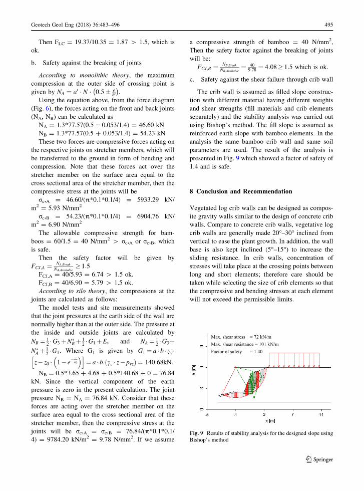
c. Safety against the shear failure through crib wall
The crib wall is assumed as filled slope construc-
tion with different material having different weights
and shear strengths (fill materials and crib elements
separately) and the stability analysis was carried out
using Bishop’s method. The fill slope is assumed as
reinforced earth slope with bamboo elements. In the
analysis the same bamboo crib wall and same soil
parameters are used. The result of the analysis is
presented in Fig. 9 which showed a factor of safety of
1.4 and is safe.
8 Conclusion and Recommendation
Vegetated log crib walls can be designed as compos-
ite gravity walls similar to the design of concrete crib
walls. Compare to concrete crib walls, vegetative log
crib walls are generally made 20°–30° inclined from
vertical to ease the plant growth. In addition, the wall
base is also kept inclined (5°–15°) to increase the
sliding resistance. In crib walls, concentration of
stresses will take place at the crossing points between
long and short elements; therefore care should be
taken while selecting the size of crib elements so that
the compressive and bending stresses at each element
will not exceed the permissible limits.
Max. shear stress = 72 kN/mMax. shear resistance = 101 kN/mFactor of safety = 1.40
Fig. 9 Results of stability analysis for the designed slope using
Bishop’s method
Geotech Geol Eng (2018) 36:483–496 495
123
For external stability analysis, the same procedure
for concrete crib with some additional considerations
in mobilisation of friction and earth pressure can be
followed. But for the internal stability analysis a
contribution from vegetative cuttings can also be
taken into consideration, if there exists a substantial
amount of vegetative cuttings with relatively longer
embedment length and good fill material with good
compaction. However, if the contribution of the
vegetative parts (cuttings) is very small compared to
the strength of crib structure it can be neglected in the
initial analysis and design.
Experiences on different soil bioengineering works
carried out in stabilising road side slopes in Nepal
(after monitoring the slope for more than 5 years)
showed that, if there are no significant slope move-
ments or erosions processes observed, it can be
assumed that the slope has been stabilised fully by
regaining its strength with the help of plants through
root reinforcement and increase in cohesion. After
5 years the slope will be stabilised further by natural
processes of revitalisation of vegetation or improve-
ment in other slope parameters. In this situation, no
further safety check is required. However, at this
stage also there is a possibility to calculate a factor of
safety to verify the desired level of safety.
Based on the results of past constructions and the
past experiences, a consideration of the future
situation of the planned log crib wall should also be
made in the design so that the slope would remain
stable with the help of grown plants after the decay of
wooden crib elements. To ensure the serviceability of
the retaining structure, the log crib wall should be
well monitored and regular maintenance of vegeta-
tion at site should be carried out. When there is lack
of past experience, the designed retaining structure
should be monitored on a regular basis and appro-
priate safety measures shall be taken.
Acknowledgements The academic support from University
of Natural Resources and Life Sciences (BOKU) and financial
support from Austrian Exchange Service (OAD) of Austrian
Development Cooperation is gratefully acknowledged. Open
access funding provided by University of Natural Resources
and Life Sciences Vienna (BOKU).
Open Access This article is distributed under the terms of the
Creative Commons Attribution 4.0 International License
(http://creativecommons.org/licenses/by/4.0/), which permits
unrestricted use, distribution, and reproduction in any medium,
provided you give appropriate credit to the original author(s)
and the source, provide a link to the Creative Commons
license, and indicate if changes were made.
References
Brandl H (1980) Tragverhalten und Dimensionierung von
Raumgitterstutzmauern (Krainerwanden)-Bundesminis-
terium fur Bauten und Technik, Straßenforschung Heft
141, Vienna, Austria, pp 115–220
Brandl H (1984) Systeme von Raumgitterstutzmauern, Erdseits
offene Raumgitterstutzmauern, Bundesministerium fur
Bauten und Technik, Straßenforschung Heft 251, Teil 1,
Vienna, Austria, pp 86–97
Brandl H (1987) “Konstruktive Hangsicherungen, Sonderdruck
aus dem Grundbautaschenbuch” Dritte Auflage, Teil 3.Wilhelm Ernst & Sohn, Berlin, pp 357–375
Coppin,NJ, Richards IG (1990) Use of vegetation in civil
engineering. CIRIA, London, pp 66–73, 87–91, 146–148
and 177–187
Daniels HE (1945) The statistical theory of the strength of
bundles of threads. I. Proc R Soc Math Phys Eng Sci 183
(995):405–435
Gray D, Leiser A (1982) Biotechnical slope protection and
erosion control. Van Nostrand Reinhold, New York
Hidalgo RC, Kun F, Herrmann HJ (2002) Bursts in a fiber
bundle model with continuous damage. Phys Rev E
64:066122. doi:10.1103/PhysRevE.64.066122
Highway Agency London (1997) Design manual for road and
bridges volume 2 section 1, part 4-BA 68/97, design of
crib retaining walls. Published jointly by The Highway
Agency, The Scottish Office Development Department,
The Welsh Office Road Department, and The Department
of The Environment for Northern Ireland, London
Morgan RPC, Rickson RJ (1995) Slope Stabilization and ero-
sion control: a bioengineering approach. E & FN Spon,
New York, pp 1–47 and 221–248
Pollen N, Simon A (2005) Estimating the mechanical effects of
riparian vegetation on stream bank stability using a fiber
bundle model. Water Resour Res 41:W07025. doi:
10.1029/2004WR003801
Preti F, Giadrossich F (2009) Root reinforcement and slope
bioengineering stabilization by Spanish Broom (Spartiumjunceum L.). Hydrol Earth Syst Sci 13:1713–1726.
www.hydrol-earth-syst-sci.net/13/1713/2009/
Schiechtl HM, Bergmann W (1994) Ingenieurbiologie, Hand-
buch zum okologischen Wasser- und Erdbau. Bauverlag
GmbH, Wiesbaden und Berlin, pp 55–61 and 85–130
Schuppener B (2001) Die Bemessung von Boschungsis-
cherungen mit Pflanzen. Geotechnik J 24(3):175–185
Wu TH (2006) Root reinforcement: analysis and experiments.
In: Proceedings of the international conference on eco-
engineering: the use of vegetation to improve slope sta-
bility, Thessaloniki, Sept 2004
Wu TH, McKinnell WP, Swanston DN (1979) Strength of tree
roots and landslides on Prince of Wales Island, Alaska.
Can Geotech J 16:19–33
496 Geotech Geol Eng (2018) 36:483–496
123