analysis of link availability in fso-ofdm system under
TRANSCRIPT

Article
Analysis of Link Availability in FSO-OFDM System under Various Climatic Conditions Selvi M. Rajendrakumar1,a,* and Murugesan Karruppaswamy2,b
1 Department of ECE, Saveetha Engineering College, Thandalam, Chennai, India 2 Department of ECE, Sree Sastha Institute of Engineering & Technology, Chembarambakkam, Chennai, India E-mail: [email protected] (Corresponding author), [email protected] Abstract. Free Space Optics (FSO) is an emerging solution for the last mile broad band connectivity where deployment of fiber is expensive. This wireless technology has attracted the researchers due to the ease of erecting along the windows and terrace and the abundant bandwidth available in the unlicensed band. Combining OFDM with FSO gives a hybrid technique – OFDM based FSO or FSO-OFDM in which OFDM symbol modulates the light that passes through free space. Various predictable and unpredictable phenomena cause variation in the light that causes the fading effect of the received signal. Besides the atmospheric effect, the signal power varies within the symbol. The link availability has been calculated by setting threshold power at the receiver. The simulation of the OFDM based FSO system under three climatic conditions namely summer, winter and rainy has been observed that shows the link availability is 99.3% for summer, 98.32% for winter and 98.99% for rainy condition. Under worst climatic condition link availability is 98.17%. Thus FSO- OFDM is able to provide better connectivity even under any atmospheric condition. Keywords: FSO-OFDM, link margin, predictable attenuation, unpredictable attenuation, link availability.
ENGINEERING JOURNAL Volume 19 Issue 1 Received 21 December 2013 Accepted 30 September 2014 Published 30 January 2015 Online at http://www.engj.org/ DOI:10.4186/ej.2015.19.1.85

DOI:10.4186/ej.2015.19.1.85
86 ENGINEERING JOURNAL Volume 19 Issue 1, ISSN 0125-8281 (http://www.ej.eng.chula.ac.th/eng/)
1. Introduction Free Space Optics (FSO) is also called Wireless Optics (WO) uses the unlicensed band of frequency to transmit the data over a short distance. Increase in the demand of high bandwidth for next generation access network. Due to the ease of installation along the window, terrace etc. it is preferred for last mile access technology [1]. Using near red to infrared lasers, high bandwidth data can be transmitted using point to point terrestrial short span link. It has the advantage of less Electromagnetic Magnetic interference, high bandwidth available, low power usage and simple receiver design [2]. But at the same time the link availability depends on the climatic condition [3–5]. This technology is protocol independent that can provide full duplex data transmission. One of the important requirements for a FSO link establishment is the clear Line Of Sight (LOS) and proper alignment of the transmitter and the receiver and the receiver design [6].
FSO can be used for satellite uplink /downlink, terrestrial link (short/long distance), intersatellite communication and deep space probing. The FSO link and its LOS connectivity are affected greatly by the atmospheric condition. Large transmitter power is required to overcome the fading effect of the FSO environment which cannot be increased beyond eye safety limit [7]. When fade margin is quite high, the link is unavailable and the transmission is interrupted. Meteorological effects like fog, rain, mist, haze, scintillation etc. cause the light intensity to fluctuate [8, 9]. Attenuation of the optical signal in free space may also be caused by atmospheric phenomena like absorption and scattering. Thus the rate of occurrence of such adverse climatic condition limits the availability of the FSO link.
OFDM being a parallel transmission system widely used to overcome the effect of multipath propagation in wireless applications. OFDM is combined with FSO to provide hybrid technology that can take the advantage of both OFDM and the FSO systems. While combining the two techniques, compatible system parameters have to be chosen. In the previous work it was suggested to use BPSK baseband modulation and the weak turbulent atmospheric condition that was modeled by lognormal distribution [10–12]. In continuation of the above work, the strong turbulent atmospheric condition is modeled by gamma-gamma distribution [13].
The power level of the OFDM signal varies from symbol to symbol, so the link margin under varying power level is calculated for different climatic condition. The performance of FSO in temperate climatic condition is done extensively by many researchers [14–16]. Under tropical condition, little work has been carried out so far. Indian climate being tropical, in this paper it is considered for simulation. Section 2 deals with the various climatic conditions and the associated formulae to represent these conditions. Simulation outputs consist of link margin for different power levels, link distance and the link availability under various climatic conditions are provided in section 3. The detail of link availability is discussed in section 4 and section 5 gives the conclusion of the study.
2. FSO-OFDM System The hybrid technique FSO-OFDM system consists of generating OFDM in the baseband domain which is used to modulate the optical source. Thus the RF signal is converted into light that is subjected to varying climatic conditions. The complex OFDM signal is given as [18]
21
1
0
( ) ( )j ktK
TOFDM kT
s t a e w nT
(1)
where T is the symbol duration, ak is the data bits, and w (.) is the rectangular window function [17]. The OFDM signal with N subcarriers modulates the intensity of laser diode and it is considered to be
linear. The optical power form the diode is represented as [18]
1
0
( ) ( )N
t n n
n
P t P m s t
(2)
where Pt is the average transmitted optical power, mn is the Optical Modulation Index (OMI) for each subcarrier and the total OMI is given as [18]
1
2
total
0
1m
N
n
n
mN
(3)
For an FSO link, the field at any point of time can be written as product of free space attenuation and stochastic amplitude to describe the field variation. The free space attenuations are categorized as

DOI:10.4186/ej.2015.19.1.85
ENGINEERING JOURNAL Volume 19 Issue 1, ISSN 0125-8281 (http://www.ej.eng.chula.ac.th/eng/) 87
predictable and unpredictable attenuation. Geometric and molecular attenuation are the predictable attenuations whereas rain attenuation, snow attenuation, atmospheric attenuation, haze attenuation and scintillation attenuation are unpredictable attenuations. All these factors are summarized as power link margin that gives the minimum power to maintain the link or connectivity. When the transmitted power after being attenuated by all attenuating factors considered here, reaches the receiver must be detectable hen link power exceeds the link margin and it is known as link availability. The power link margin Mlink is given as:
( ) ( ) ( ) ( )Link o rM dB P dBm S dBm Loss dB (4)
( ) ( ) ( ) ( ) ( )geo atm rain scin snowLoss Att dB Att dB Att dB Att dB Att dB (5)
where Po is total power from the source
rS is sensitivity of the receiver
geoAtt is geometric attenuation
atmAtt is atmospheric attenuation
rainAtt is rain attenuation
scinAtt is scintillation attenuation and snowAtt is snow attenuation.
3. System Attenuation Parameters FSO system used for outdoor terrestrial link is affected by both predictable and unpredictable attenuations. The atmosphere is a heterogeneous mixture of different molecules and suspended particles of varying size. Besides this the climatic conditions plays a vital role in the composition of the atmosphere. 3.1. Geometric Attenuation This is a predictable attenuation that is fixed for the selected FSO system under study, since it is dependent on the geometry of the transmitter and receiver used in the system. When the light beam propagates, it diverges along the path of travel and hence not all the light emitted from the surface of emitter reaches the receiver. So the loss in the signal is represented by [19]:
2
geo
/ 4( )Att d
capture capture
S L
S S
(6)
where is beam divergence, L is the distance between the transmitter and the receiver, is the
capture area of the receiver and is spot surface at a distance L.
3.2. Molecular Attenuation It is also a predictable attenuation that is a function of operating wavelength. But the values observed for
this attenuation is very low, of the order of 0.01 dB and 0.13 dB for short wavelength 550 m and longer
wavelength 1550 m respectively. Hence it has negligible contribution to the total loss for the FSO- OFDM system under study. 3.3. Atmospheric Attenuation This is an unpredictable attenuation caused by the absorption and scattering of light by the gas molecules and aerosol present in the atmosphere. With proper choice of wavelength, the absorption can be reduced. But scattering cannot be avoided and Mie scattering predominantly causes atmospheric attenuation [20], [21]. The atmospheric attenuation coefficient due to scattering is expressed as:
Le (7)
where is the specific attenuation coefficient per unit of length. The value of is obtained from the following relation [22]:

DOI:10.4186/ej.2015.19.1.85
88 ENGINEERING JOURNAL Volume 19 Issue 1, ISSN 0125-8281 (http://www.ej.eng.chula.ac.th/eng/)
3.912
550
q
v
(8)
where v is the visibility (km);
- is the wavelength (nm); q- is the size distribution of diffusing particles.
The value of q is related to the visibility and is expressed as [23]
1.6 for 50 km
1.3 for 6 km 50 km
( ) 0.16 0.34 for 1 km 6 km
0.5 for 0.5 km 1 km
0 for 0.5 km
v
v
q v v v
v v
v
(9)
3.4. Rain Attenuation Tropical region is characterized by moisture and are subjected to heavy rainfall over a period of time in a year. The tropical rain causes major impairment to the FSO link availability. The attenuation of the rain is independent of the wavelength. It is a function of precipitation intensity R (mm/ hr) and is given as [24]:
2/31.076rainAtt R (10)
3.5. Snow Attenuation Attenuation due to snow is also a function of wavelength (nm) and snow intensity S (mm / hr). Based on the altitude of the snowfall, attenuation can be classified as wet snow (altitude less than 500 m) and dry snow (altitude greater than 500 m). The specific attenuation due to snow rate S is given as [25, 26].
b
snow aS (11)
where a and b are defined for the two types of snow as
41.023 10 3.7855466a and b=0.72, for wet snow; 55.42 10 5.4958776a and b= 1.38, for dry snow.
Hence the attenuation for the two condition is obtained by substituting the ‘a’ and ’b’ values in Eq.( 11) and given as
0.72(0.000123 3.7855466)snowAtt S (dB/km), wet snow
1.38(0.00000542 5.4958776)snowAtt S (dB/km), dry snow (12)
3.6. Scintillation Scintillation is the temporal and spatial variations of light intensity due to the atmospheric turbulence. Atmospheric turbulence occurs during hot summer condition, when the sun heats up the surrounding air that causes the air packet to move in turbulent manner. Some of the air packets behave like lens and may focus or defocus the light passing through it. The magnitude of scintillation is determined by the Rytov theory [24]. It defines the scintillation index as
2 7/6 2 11/61.23scin nk C L (13)
where 2
nC is refractive index structure parameter (m-2/3) and its value depends on the extent of turbulence
in the atmosphere given as

DOI:10.4186/ej.2015.19.1.85
ENGINEERING JOURNAL Volume 19 Issue 1, ISSN 0125-8281 (http://www.ej.eng.chula.ac.th/eng/) 89
16
2 14
13
10 for low turbulence
10 for medium turbulence
10 for high turbulence
nC
(14)
Attenuation due to scintillation can be calculated as
210log 1scin scin (15)
4. Link Availability A correct operation of the system is expected only if the link power margin calculated from the expression (1) is sufficient that can overcome the attenuation due to different factors and the receiver sensitivity is sufficient to detect the minimum power from the link and so the link is said to be available. In a link, the period of unavailable begins with the start of 10 consecutive Severely Errored Seconds (SES) [27]. A new period of available time begins at the onset of 10 consecutive non-SESs. The Severely Errored Second is a one-second period whose Bit Error Rate (BER) exceeds a given value. The Errored Second (ES) is a one-second period with one or more errors [27]. The total unavailability time tun is the sum of partial time intervals when the link is not accessible during the observation period t. Consequently the percentage of
link unavailability is given as [5]
.100unun
total
tP
t (16)
The power level of the OFDM varies and during some of the OFDM symbol duration, it is possible that power may fall below threshold limit and link may be unavailable. For the FSO-OFDM system, the proper selection of threshold must be done to find the link availability. The threshold is assumed as
min( ) / 2th avgP P P (17)
where Pth is the threshold power; Pavg is the average power; and Pmin is the minimum power of the OFDM symbol.
The link is said to be available if OFDM symbol power is greater than the threshold.
5. Results and Discussion The FSO- OFDM system is simulated in MATLAB. The OFDM symbols are generated based on the IEEE 802.11 standard. 106 random information bits are considered for one transmission. They are superimposed on the 52 subcarriers that are PSK based band modulated and then 64 point IFFT is taken. Atmospheric condition is considered to be worst with all the factors affecting the OFDM signal. The OFDM signal amplitude swings over Pmax to Pmin which causes the power transmitted to fluctuate over a range of values as shown in Fig. 1.

DOI:10.4186/ej.2015.19.1.85
90 ENGINEERING JOURNAL Volume 19 Issue 1, ISSN 0125-8281 (http://www.ej.eng.chula.ac.th/eng/)
Fig. 1. OFDM symbol power variation.
For the purpose of simulation, the 1 Mbps data rate is considered. For the given number of OFDM symbols, peak power, minimum power and average power is obtained and a threshold limit is set. The other parameters used for simulation is given in Table 1.
Table 1. Simulation parameter.
Symbol Description Value
L Distance between the transmitter and the receiver 1000m Sr Receiver sensitivity -45dBm
Beam Divergence 3 m rad
Wavelength 850 nm
v Visibility 1000m R Rain precipitation (Worst case) 150 mm / hr S Haze precipitation (Worst case) 20 n Number of bits in one transmission 106 N N-point FFT 64 n_sc Number of Subcarriers 52 T Symbol duration 3.2 (μs) CP Cyclic Prefix duration 0.8 (μs)
Using the above parameters, the OFDM symbols are generated and its power variation along with the
variation in link margin under worst condition is shown in Fig. 2. The worst condition includes the combined effect of rain, snow, scintillation, geometric and atmospheric attenuation. It is observed that the base band OFDM symbol power varies from to -13.25 dBm to -9.25 dBm. Over the variation of the input power, the link margin is obtained in the range of -73.25 dB to -77.25 dB. Since there is a linear relationship between the input power and the link margin, as the power level increases, the link margin also increases proportionately.

DOI:10.4186/ej.2015.19.1.85
ENGINEERING JOURNAL Volume 19 Issue 1, ISSN 0125-8281 (http://www.ej.eng.chula.ac.th/eng/) 91
Fig. 2. Link margin variation with OFDM symbol power.
Driving circuit for laser that is modulated by OFDM signal has to be chosen such a way that the emitted power should be greater than the maximum link margin. The atmospheric condition is random in nature. But at the same time, it depends on the geographic location that determines the climate of the region. As discussed above, all the attenuation effects are not present in the atmosphere simultaneously. India is located in the tropical region that is characterized by the four different climates in a year viz. summer, winter, rain and spring. The spring season has moderate climate, hence the link availability is studied for the three different climatic conditions which is considered here. Climate 1: Hot Summer Condition
During hot summer condition, the air packets heats up that produces lens like effect causing the focusing and defocusing of light passing through it. Under this climatic condition, the scintillation attenuation is prominent than the other attenuation effect. There is very meagre chance of rain and no chance of snow in this consideration. Hence only one unpredictable attenuation loss is considered. Fig. 3(a) and 3(b) shows the variation of link margin with link length and the wavelength. It is observed from Fig. 3(a) that as link length increases the link margin decreases It is seen that as link length increases the link margin decreases from -17 dB to -55 dB, -15 dB to -53 dB and -14 dB to -50.5 dB for minimum, average and maximum symbol power respectively. At all transmitted power level the range of link margin variation is maintained. It is due to the linear relation between the link margin and the link length.
(a)
(b)
Fig. 3. Hot summer climatic condition: (a) Link Margin vs. Link Length; (b) Link Margin vs. Wavelength.
Figure 3(b) shows the variation of link margin for different wavelength in the range of 850 nm to 1550 nm. Again the variation of the link margin is obtained for three different power level used in Fig. 3(a). It is observed that as wavelength increases, the link margin also increases. But this increase in link margin is over

DOI:10.4186/ej.2015.19.1.85
92 ENGINEERING JOURNAL Volume 19 Issue 1, ISSN 0125-8281 (http://www.ej.eng.chula.ac.th/eng/)
a small range only. It varies 20 dB to 22 dB for maximum power from the OFDM symbol for the range of wavelength considered in the simulation. The variation in the link margin over the same wavelength is in the range of 18 dB to 20 dB for average power of the OFDM symbol while it is in the range of 16 dB to18 dB for minimum power of the OFDM symbol. Climate 2: Winter Condition
The winter climate is characterized by the presence of fog, haze and mist. The amount of scattering particle is given in terms of haze precipitation intensity ‘S’. For winter climatic condition, S is considered to be 20. Figure 4(a) and (b) show the variation of link margin with link length and the wavelength.
(a)
(b)
Fig. 4. Winter condition: (a) Link Margin vs. Link Length; (b) Link Margin vs. Wavelength.
For small link length, the link margin is high. But as the distance between the transmitter and the receiver increases, the link margin decreases as shown in Fig. 4(a). The drop in link margin is very steep from 1km to 2 km, after that it decreases very gradually. From the Fig. 4(b), it is observed that link margin decreases as wavelength increases. But the variation is over a small range of the order of 0.5dB. It is due to the fact that, the haze precipitation is not dependent on wavelength but the wavelength affects the snow attenuation by a factor of 0.0001023. Only atmospheric attenuation and scintillation varies with wavelength and hence the variation in the link margin is about 0.5 dB. Climate 3: Rainy Condition
Tropical climate is characterized by heavy rainfall. In India only during certain part of the year, rainfall occurs. Hence the link availability will be affected during such duration. Fig. 5(a) and (b) shows the variation of link margin with link length and the wavelength. As in the case of summer condition, the link margin decreases with link length and it is shown in Fig. 5(a). The decrease is steep between1 km to 2 km and then it decreases gradually. After 3 km, the link margin is very low of the order of-50 dB. As shown in Fig. 5(b) the link margin varies over very small range, since the rain precipitation does not depend on the wavelength.
DOI:10.4186/ej.2015.19.1.85
ENGINEERING JOURNAL Volume 19 Issue 1, ISSN 0125-8281 (http://www.ej.eng.chula.ac.th/eng/) 93
(a)
(b)
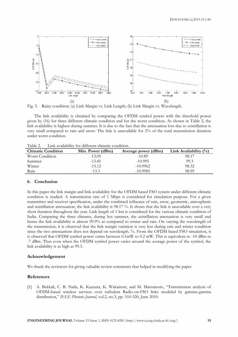
Fig. 5. Rainy condition: (a) Link Margin vs. Link Length; (b) Link Margin vs. Wavelength.
The link availability is obtained by comparing the OFDM symbol power with the threshold power given by (16) for three different climatic condition and for the worst condition. As shown in Table 2, the link availability is highest during summer. It is due to the fact that the attenuation loss due to scintillation is very small compared to rain and snow. The link is unavailable for 2% of the total transmission duration under worst condition. Table 2. Link availability for different climatic condition.
Climatic Condition Min. Power (dBm) Average power (dBm) Link Availability (%)
Worst Condition -13.05 -10.89 98.17 Summer -13.45 -10.995 99.3 Winter -13.12 -10.9962 98.32 Rain -13.3 -10.9985 98.99
6. Conclusion In this paper the link margin and link availability for the OFDM based FSO system under different climatic condition is studied. A transmission rate of 1 Mbps is considered for simulation purpose. For a given transmitter and receiver specification, under the combined influence of rain, snow, geometric, atmospheric and scintillation attenuation, the link availability is 98.17 %. It shows that the link is unavailable over a very short duration throughout the year. Link length of 1 km is considered for the various climatic condition of India. Comparing the three climates, during hot summer, the scintillation attenuation is very small and hence the link availability is almost 99.9% as compared to winter and rain. On varying the wavelength of the transmission, it is observed that the link margin variation is very less during rain and winter condition since the two attenuations does not depend on wavelength. %. From the OFDM based FSO simulation, it is observed that OFDM symbol power varies between 0.1mW to 0.2 mW. This is equivalent to -10 dBm to -7 dBm. Thus even when the OFDM symbol power varies around the average power of the symbol, the link availability is as high as 99.3.
Acknowledgement We thank the reviewers for giving valuable review comments that helped in modifying the paper.
References [1] A. Bekkali, C. B. Naila, K. Kazaura, K. Wakamori, and M. Matsumoto, “Transmission analysis of
OFDM-based wireless services over turbulent Radio-on-FSO links modeled by gamma-gamma distribution,” IEEE Photonic Journal, vol.2, no.3, pp. 510-520, June 2010.

DOI:10.4186/ej.2015.19.1.85
94 ENGINEERING JOURNAL Volume 19 Issue 1, ISSN 0125-8281 (http://www.ej.eng.chula.ac.th/eng/)
[2] Y. Zhao and J. Vongkulbhisal, “Design of visible light communication receiver for on-off keying modulation by adaptive minimum-voltage cancellation,” Engineering Journal, vol.17, no. 4, pp.126–129, 2013.
[3] A. Prokes and V. Skorpil, “Estimation of free space optics systems availability based on meteorological visibility,” in Proc. of IEEE Latin-American Conference on Communications, pp. 1–4, 2009.
[4] M. S. Awan, L. C. Horwarth, S. S. Mohammad, E. Leitgeh, F. Nadeem, and M. S. Khan, “Characterization of fog and snow attenuations for free space optical propagation,” Journal of Communications, vol. 4, no. 8, pp. 533–545, Sept. 2009.
[5] R. Kvicala, V. Kvicera, M. Graner, and O. Fiser, “BER and link availability measured on FSO link,” Radio Engineering, vol. 16, no. 13, pp. 7–12, Sept. 2007.
[6] M. S. Awan, E. Leitgeb, B. Hillbrand, F. Nadeem, and M. S. Khan, “Cloud attenuations for free space optical links,” in Proc. of International Workshop on Satellite and Space Communications, 2009, pp. 274–278.
[7] S. Bloom, E. Korevaar, J. Schuster, and H. Willebrand, “Understanding the performance of free-space optics,” Journal of Optical Networking, vol. 2, no. 6, pp. 178–200, 2003.
[8] F. H. Hamat, A. S. M. Supa’at, and F. D. Mahad, “Simulation of FSO transmission at Petaling Jaya due to attenuations effect,” Journal of Electrika, vol. 12, no. 1, pp. 30–34, 2010.
[9] S. A. Zabidi, W. Al Khateeb, Md. R. Islam, and A. W. Naji, “The effect of weather on free space optics communication (FSO) under tropical weather conditions and a proposed setup for measurement,” International Conference on Computer and Communication Engineering (ICCCE), 2010, pp. 1–5.
[10] M. Selvi and K. Murugesan, “Performance of orthogonal frequency division multiplexing in the weak turbulent regime of free space optical communication system,” Journal of Optics, vol. 12, no. 14, pp. 1–7, Oct. 2012.
[11] L. C. Andrews, R. L. Philips, and C. Y. Hopen, Laser Beam Scintillation with Applications. Bellingham, WA: SPIE, 2001.
[12] L. C. Andrews and R. L. Philips, Laser Beam Propagation through Random Media, 2nd ed., Bellingham, WA: SPIE, 2005.
[13] M. Selvi and K. Murugesan, “Performance comparison of OFDM based FSO communication system under log-normal and gamma-gamma distribution,” Journal of Optical Communications, to be published.
[14] M. Al. Nabonusi, M. Sizun, and F. de Fornell, “Propagation of optical and infrared waves in the atmosphere,” SPIE Journal, pp. 1–4, 2003.
[15] A. K. Virk, J. Singh Malhotra, and S. Pahuja, “Link margin optimization of free space optical link under the impact of varying meteorological conditions,” International Journal of Engg. Science and Tech., vol. 4, no. 3, pp. 1120–1125, Mar. 2012.
[16] M. Saleem, E. Leitgeh, M. S. Khan and C. Capsoni, “A new method of predicting continental fog attenuation for terrestrial optical wireless link,” in Proc. 3rd International Conference on Next Generation Mobile Application, Services and Tech., 2009, pp 245–250.
[17] R. V. Nee and R. Prasad, “OFDM for Wireless Multimedia Communications,” Norwell, MA: Artech House, 2000.
[18] J. Armstrong, “OFDM for optical communications,” Journal of Lightwave Technology, vol. 27, no. 3, pp. 189-204, 2009.
[19] O. Bouchet., H. Sizun, C. Boisrobert, F. De Fornel, and P. Favennec, Free Space Optics: Propagation and Communication, UK: ISTE Ltd., 2006.
[20] I. I. Kim, B. McArthur, and E. Korevaar, “Comparison of laser beam propagation at 785 nm and 1550 nm in fog and haze for optical wireless communications,” In Proc. of SPIE Optical Wireless Communications III, ed., vol. 4214, 2001, pp. 26–37.
[21] Propagation data required for the design of terrestrial free-space optical links, ITU-R Recommendation P. 1814, 2007.
[22] P. W. Kruse, L. D. McGlauchlin, and R. B. McQuistan, Elements of Infrared Technology: Generation, Transmission, and Detection. New York: John Wiley & Sons, 1962.
[23] Prediction methods required for the design of terrestrial free-space optical links, ITU-R Recommendation P. 1814, 2007.
[24] T. H. Carbonneau and D. R. Wisely, “Opportunities and challenges for optical wireless; the competitive advantage of free space telecommunications links in today’s crowded market place,” in Proc. SPIE 3232, Wireless Technologies and Systems: Millimeter-Wave and Optical, Jan. 1998, pp. 119-128.
[25] F. Nadeem, V. Kvicera, M. Saleem Awan, E. Leitgeb, S. Sheikh Muhammad, and G. Kandus, “Weather effects on hybrid FSO/RF communication link,” IEEE Journal On Selected Areas In Communications, vol. 27, no. 9, pp. 1687–1697, Dec. 2009.

DOI:10.4186/ej.2015.19.1.85
ENGINEERING JOURNAL Volume 19 Issue 1, ISSN 0125-8281 (http://www.ej.eng.chula.ac.th/eng/) 95
[26] S. Sheikh Muhammad, P. Köhldorfer, and E. Leitgeb, “Channel modeling for terrestrial free space optical links,” in Proc. 7th International Conference Transparent Optical Networks, 2005, pp. 407-410.
[27] ITU-T G.827: Availability performance parameters and objectives for end-to-end international constant bit-rate digital paths, ITU, Geneva, 2003.
