an2357: sine voltage powered 3-phase permanent...
TRANSCRIPT
AN235711/2002
Sine Voltage Powered 3-Phase Permanent Magnet Motor with Hall Sensor
Application Note
Fre
esc
ale
Se
mic
on
du
cto
r, I
nc
...
By Jiri RybaRoznov System Application LaboratoryRoznov, Czech Republic
Introduction
This application note describes the control of a 3-phase PM (permanent magnet) motor with a Hall sensor powered by a sine voltage. It is based on Freescale’s MC68HC908MR8 dedicated to motor control applications. The software design uses the 908MR Quick Start development tool developed by Freescale.
This application note includes:• Features of Freescale’s MC68HC908MR8• Basic motor theory• System design concept• Hardware implementation• Software design including the PC master visualization tool
Overview
The concept of the application is a speed closed loop 3-phase synchronous PM drive using a Hall sensor. The main goal is to attain the lowest possible audible noise level of the motor. The motor is powered by a sine voltage to achieve low noise, while the sine voltage is synchronized with the Hall-effect sensor by a phase-locked loop (PLL). Speed of the motor is controlled by the voltage amplitude, while the voltage frequency matches the actual speed of the motor. The application contains a torque limitation, which is realized by a feed forward control algorithm. The algorithm is based on the difference between the power voltage and the induced voltage.
For More Information On This Product,
Go to: www.freescale.com

AN2357/D
F
ree
sca
le S
em
ico
nd
uc
tor,
I
Freescale Semiconductor, Inc.n
c..
.
MC68HC908MR8 Features
The Freescale MR8 Family members are well suited for digital motor control. These microcontroller units (MCUs) offer many dedicated peripherals such as a pulse width modulation (PWM) module, analog-to-digital converter (ADC), timers, serial communication interface (SCI), on-board FLASH, and random-access memory (RAM).
A typical member of the family, the MC68HC908MR8, provides the following peripheral blocks:
• MCU core 8 bit / 8 MHz• 12-bit, 6-channel center-aligned or edge-aligned PWM module with
optional independent and complementary mode• 8 Kbytes of on-chip electrically erasable in-circuit programmable read-
only memory (FLASH EPROM)• 256 bytes of on-chip RAM• 10-bit 4-to-7 channel ADC• Two 16-bit 2-channel timer modules• Serial communications interface module (SCI)• Clock generator module (CGM)• Computer operating properly (COP) watchdog timer• Low-voltage inhibit (LVI) module with software selectable trip points• Software-programmable, PLL based frequency synthesizer for the core
clock
The application uses the PWM block set in complementary center-aligned mode. The PWM frequency is 16 kHz.
Target Motor Theory
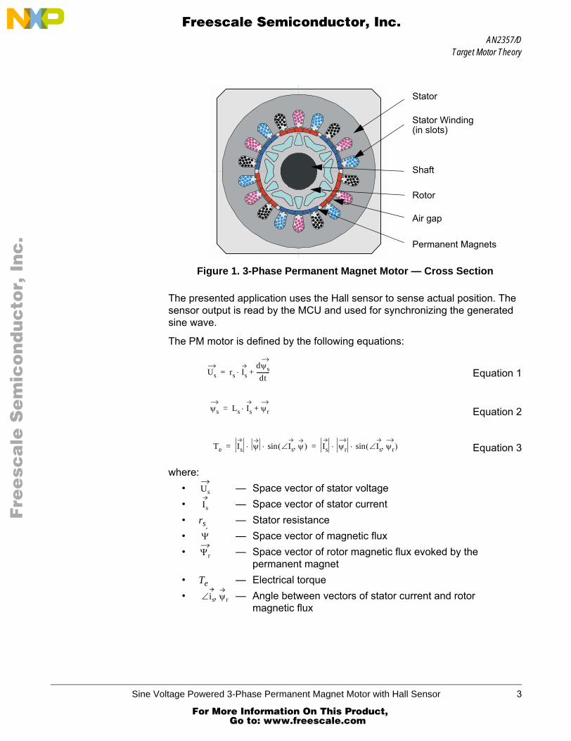
The PM motor is a rotating electric machine where the stator is a classic 3-phase stator, like that of an induction motor. The rotor has surface-mounted permanent magnets (see Figure 1).
If the stator is powered by a 3-phase sinusoidal voltage, the PM motor is equivalent to an induction motor with the air gap magnetic field produced by a permanent magnet. This means that the rotor magnetic field is constant. The use of a permanent magnet to generate a substantial air gap magnetic flux, makes it possible to design highly efficient PM motors. The PM motors provide a range of advantages in the design of modern motion control systems, such as high efficiency, high torque per volume, and low moment of inertia.
2 Sine Voltage Powered 3-Phase Permanent Magnet Motor with Hall Sensor
For More Information On This Product, Go to: www.freescale.com
AN2357/DTarget Motor Theory
F
ree
sca
le S
em
ico
nd
uc
tor,
I
Freescale Semiconductor, Inc.n
c..
.
Figure 1. 3-Phase Permanent Magnet Motor — Cross Section
The presented application uses the Hall sensor to sense actual position. The sensor output is read by the MCU and used for synchronizing the generated sine wave.
The PM motor is defined by the following equations:
Equation 1
Equation 2
Equation 3
where:• — Space vector of stator voltage• — Space vector of stator current• rs — Stator resistance• — Space vector of magnetic flux• — Space vector of rotor magnetic flux evoked by the
permanent magnet• Te — Electrical torque• — Angle between vectors of stator current and rotor
magnetic flux
Stator
Stator Winding(in slots)
Shaft
Rotor
Air gap
Permanent Magnets
Us rs Is⋅dψsdt
---------+=
ψs Ls Is ψr+⋅=
Te Is ψ Is∠ ψ,( )sin⋅ ⋅ Is ψr Is∠ ψr,( )sin⋅ ⋅= =
Us
Is
Ψ
Ψr
is∠ ψ, r
Sine Voltage Powered 3-Phase Permanent Magnet Motor with Hall Sensor 3
For More Information On This Product, Go to: www.freescale.com

AN2357/D
F
ree
sca
le S
em
ico
nd
uc
tor,
I
Freescale Semiconductor, Inc.n
c..
.
Motor speed can be controlled by the amplitude of the voltage vector, while the direction of the voltage vector depends on the rotor position. Several methods can be used to control the voltage vector direction. The three basic method are:
1. Vector of stator voltage is placed 90° relative to the vector of rotor permanent magnet flux
2. Vector of stator current is kept 90° relative to the vector of rotor permanent magnet flux
3. Voltage vector is kept in the direction of the current vector
The most important criterion is to run the motor with maximum efficiency. In this case, the angle of current will be higher than 90° relative to the rotor permanent magnet flux, but lower than shown in method 3 above where the current has the same direction as the voltage. The motor parameters have to be known or some experimental control strategy has to be used to achieve this criterion.
Vector of Stator Voltage is Placed 90° Relative to the Vector of Rotor Permanent Magnet Flux
The control strategy keeps the vector of stator voltage at 90° relative to the vector of rotor permanent magnet flux. This control strategy is shown in Figure 2. The advantage of this strategy is control simplicity. Only knowledge of the rotor position is required.
Where three Hall sensors are used to get the rotor position, we obtain six positions per electrical revolution. To each rotor position, a vector position of stator voltage is assigned. The motor is commutated each 60°, so that the phase voltage is rectangular. This algorithm is mostly used for the control of BLDC (brushless dc) motors. Twelve commutations instead of six can be used to decrease the acoustic noise. For a more detailed description refer to References [1].
Figure 2. Voltage is 90° Relative to Rotor Flux
Ψ
Ψr
Ψs
jω.Ls.Is
Us
RsIs
E
Is
90°
4 Sine Voltage Powered 3-Phase Permanent Magnet Motor with Hall Sensor
For More Information On This Product, Go to: www.freescale.com
AN2357/DTarget Motor Theory
F
ree
sca
le S
em
ico
nd
uc
tor,
I
Freescale Semiconductor, Inc.n
c..
.
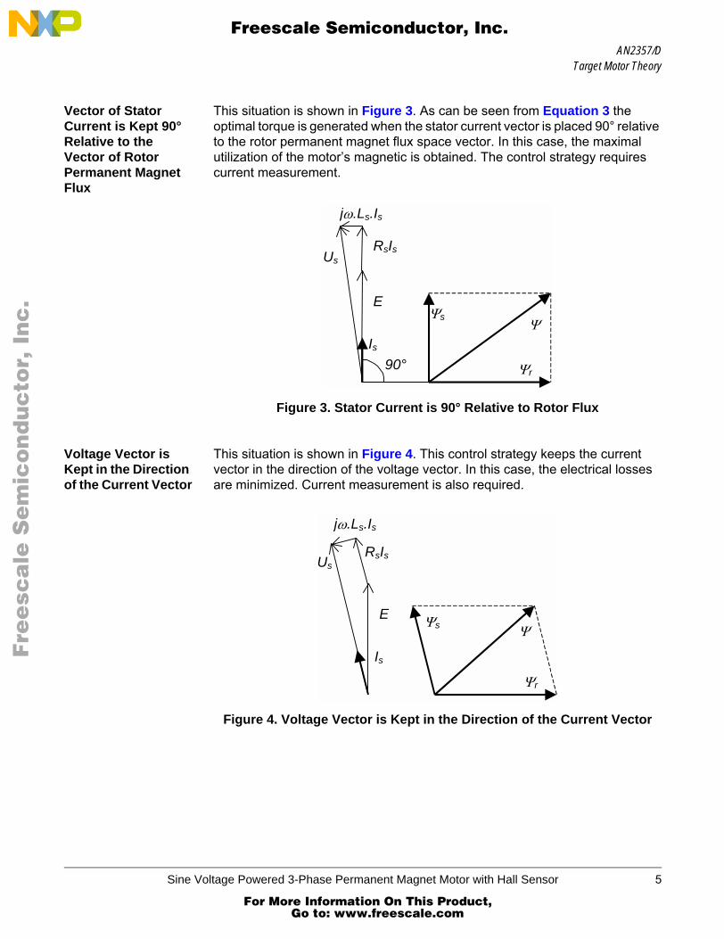
Vector of Stator Current is Kept 90° Relative to the Vector of Rotor Permanent Magnet Flux
This situation is shown in Figure 3. As can be seen from Equation 3 the optimal torque is generated when the stator current vector is placed 90° relative to the rotor permanent magnet flux space vector. In this case, the maximal utilization of the motor’s magnetic is obtained. The control strategy requires current measurement.
Figure 3. Stator Current is 90° Relative to Rotor Flux
Voltage Vector is Kept in the Direction of the Current Vector
This situation is shown in Figure 4. This control strategy keeps the current vector in the direction of the voltage vector. In this case, the electrical losses are minimized. Current measurement is also required.
Figure 4. Voltage Vector is Kept in the Direction of the Current Vector
jω.Ls.Is
Ψr
Ψs Ψ
Us RsIs
E
Is 90°
Us
jω.Ls.Is
Ψr
Ψs Ψ
RsIs
E
Is
Sine Voltage Powered 3-Phase Permanent Magnet Motor with Hall Sensor 5
For More Information On This Product, Go to: www.freescale.com

AN2357/D
F
ree
sca
le S
em
ico
nd
uc
tor,
I
Freescale Semiconductor, Inc.n
c..
.
System Concept
The control strategy is designed to optimally utilize features of the MC68HC908MR8. The application provides the following properties:
• Sine voltage powered 3-phase PM synchronous motor• Position sensing using single Hall sensor• Low motor audible noise• Torque limitation• Closed speed loop• High motor efficiency• Energy recuperation with over-voltage limitation• dc-bus voltage ripple cancellation• Manual (speed pot, start-stop switch) / PC master control (RS232)• Recognition of the spinning motor after central processor unit (CPU)
reset• Deceleration control to limit over voltage during recuperation• Over-voltage protection• Over-current protection• dc-bus voltage measuring• PC master software• Memory requirements:
– RAM — 184 bytes– FLASH — 3738 bytes
Figure 5 shows the system concept of the designed application. The application was designed to control a ventilator PM motor. Speed of the motor is controlled by the amplitude of the voltage vector, while the direction of the voltage vector depends on the rotor position. Because of the motor information, the position is obtained only twice per electrical period. The PLL is used to synchronize the calculated position with the actual one. The calculated position is updated in the PWM reload at 16 kHz, while the position resolution is 216
points per period.
The PI controller is used to control the motor speed. The voltage ripple cancellation block is independent of the dc-bus voltage. Here, controller output is absolute voltage amplitude instead of the relative value which is input to the sine wave generator.
The torque limitation is based on the voltage limitation. The absolute voltage amplitude is calculated according to motor speed and required torque limitation.
6 Sine Voltage Powered 3-Phase Permanent Magnet Motor with Hall Sensor
For More Information On This Product, Go to: www.freescale.com

AN2357/DSystem Concept
F
ree
sca
le S
em
ico
nd
uc
tor,
I
Freescale Semiconductor, Inc.n
c..
.
Figure 5. System Concept
The dc voltage limitation controls the deceleration of the motor to avoid dc-bus over voltage. In this application the voltage is kept at 16 V.
The application also contains PC master software, which supports communication between the target microcontroller and PC via an RS232 serial interface. This tool allows access to any memory location of the target processor in real time. The programmer can debug an application, as well as remotely control the application, using a user-friendly graphical environment running on a PC.
SPEED POT.
Period, Position
Recognition 1/T
Speed PI Controller
PLL
3-ph Sine Wave Generator
AD
C
I/O
68HC908MRx
I/O
3-ph PM
Motor
DC-Bus Voltage Sensing
3-ph Inverter
START/STOP
PWM
RequiredSpeed
Actual Speed
Commutation Period
Required Voltage
Required Angle
Hall Sensor Signal
12V DC
Fault
DC-Bus Current Sensing
- +Ref.
ADC
Deceleration Limitation
--
Voltage Ripple
Cancellation
Torque Limitation
Torque to Voltage
Conversion
Voltage Limitation
Relative Voltage
Sine Voltage Powered 3-Phase Permanent Magnet Motor with Hall Sensor 7
For More Information On This Product, Go to: www.freescale.com

AN2357/D
F
ree
sca
le S
em
ico
nd
uc
tor,
I
Freescale Semiconductor, Inc.n
c..
.
Hardware Design
The motor control system is designed to drive the 3-phase PM motor in a speed closed loop using a MC68HC908MR8 microcontroller. The system configuration is shown in Figure 6. The system configuration consists of:
• MC68HC908MR32 controller board with MR8 daughter board• Power stage• 3-phase PM motor with one Hall sensor
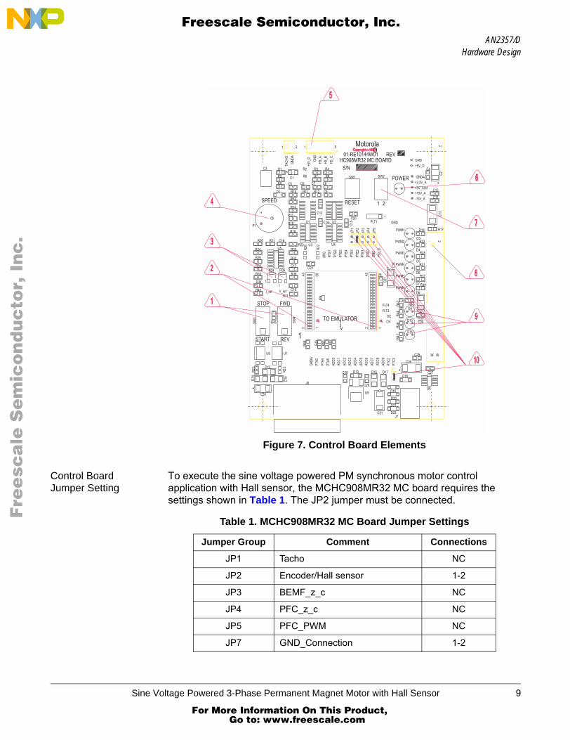
Figure 6. Hardware System Configuration
Controller Board The controller board, shown in Figure 7, has the following elements:1. Main board switches2. Emulator / MC68HC908MR32 socket enabling conection of a
MC68HC908MR8 daughter board3. dc-bus over-current and over-voltage detection4. Speed potentiometer5. Hall sensor connector6. Power indicator7. Board switches8. Connector to power stage9. User light-emitting diode (LED)
10. Hardware configuration jumpers
U1 – 68HC908MR32 MC Board U2 – AC / BLDC Power Stage U3 – 68HC908MR8 Daughter Board M1 – 3 phase PM Motor
M1
U3 U2 U1
Hall sensor cable
J2
J5
12V DC
40w flat ribbon cable
8 Sine Voltage Powered 3-Phase Permanent Magnet Motor with Hall Sensor
For More Information On This Product, Go to: www.freescale.com
AN2357/DHardware Design
F
ree
sca
le S
em
ico
nd
uc
tor,
I
Freescale Semiconductor, Inc.n
c..
.
Figure 7. Control Board Elements
Control Board Jumper Setting
To execute the sine voltage powered PM synchronous motor control application with Hall sensor, the MCHC908MR32 MC board requires the settings shown in Table 1. The JP2 jumper must be connected.
Table 1. MCHC908MR32 MC Board Jumper Settings
Jumper Group Comment Connections
JP1 Tacho NC
JP2 Encoder/Hall sensor 1-2
JP3 BEMF_z_c NC
JP4 PFC_z_c NC
JP5 PFC_PWM NC
JP7 GND_Connection 1-2
Sine Voltage Powered 3-Phase Permanent Magnet Motor with Hall Sensor 9
For More Information On This Product, Go to: www.freescale.com

AN2357/D
F
ree
sca
le S
em
ico
nd
uc
tor,
I
Freescale Semiconductor, Inc.n
c..
.
Power Stage Motorola’s embedded motion control series low-voltage (LV) BLDC power stage is designed to run 3-phase BLDC and PM synchronous motors. It operates from a nominal 12-volt motor supply. It delivers up to 30 A of rms motor current from a dc bus that can deliver peak currents of up to 46 A. In combination with one of Motorola’s embedded motion control series control boards, it provides a development platform that allows algorithms to be written and tested, without the need to design and build a power stage. It supports a wide variety of algorithms for controlling BLDC and PM synchronous motors.
PM Motor Parameters
The control algorithm was tested on a motor with the following basic parameters:
• Nominal voltage, 12 V• Three pole pairs• Three phases• One Hall sensor in phase A, so the number of pulses per revolution is
equal to the number of rotor pole pairs.
Software Design
This section describes the control algorithm design process and the software blocks implemented in the drive.
Data Flow The closed loop drive control algorithm for the sine voltage powered 3-phase PM motor with Hall sensor is described in Figure 8. The inputs are desired omega from speed pot (manual control) (or from external control (SCI)), maximal torque (torque_limit), and Hall sensor signal (Hall sensor). The output is a 3-phase PWM signal (PWM generation).
PC Master Process
The PC master process controls data exchange between the application and the SCI. The module enables reading and writing to the CPU RAM and reading the whole CPU memory.
Sensor Edge Detection
Each incoming edge on the signal from Hall sensor causes the saving of the actual timer value and setting of the capture flag. The flag is recognized in the following PWM reload, and it starts a task which is divided between two PWM reload interrupts. In the first interrupt the sine wave is synchronized, and the period of the hall sensor signal is calculated. In the following PWM reload interrupt, the “phase_increment” is calculated.
10 Sine Voltage Powered 3-Phase Permanent Magnet Motor with Hall Sensor
For More Information On This Product, Go to: www.freescale.com

AN2357/DSoftware Design
F
ree
sca
le S
em
ico
nd
uc
tor,
I
Freescale Semiconductor, Inc.n
c..
.
Figure 8. Main Data Flow
PC master process Sensor Edge Detection
SCI
Period Calculation PLL
fieldWeakening
phase_measured phase_increment
Sine Wave Synchronization
phase_actual
period_hall_sensor
Speed Ramp
omega_measured
omega_desired
omega_required
Speed Calculation
omega_required_RPM
Torque Limitation
torque_limit
v_phase_limit
Speed Controller
Ripple Cancellation
Voltage Limitation
v_phase_amplitude
Sine Wave Generation
Manual Control
Hall Sensor
Field Weakening Calculation
controller_out
PWM Generation
Sine Voltage Powered 3-Phase Permanent Magnet Motor with Hall Sensor 11
For More Information On This Product, Go to: www.freescale.com

AN2357/D
F
ree
sca
le S
em
ico
nd
uc
tor,
I
Freescale Semiconductor, Inc.n
c..
.
Period Calculation To eliminate the difference between the rotor poles, the edges from same poles are used for period calculation. The motor used has three pole pairs. The principle of period calculation is shown in Figure 9. The period is calculated on each signal edge, but the time from same edge and same pole is used for the period calculation in the current time.
Figure 9. Calculation of Hall Sensor Period
Phase-Locked Loop The PLL provides synchronization of generated sine voltage with Hall sensor signal, and maintains sine wave frequency according to the Hall sensor signal. The frequency of the sine wave is given by “phase_increment”. The actual angle of sine wave is increased by this increment at each PWM reload. The new “phase_increment” is counted, from the difference between the Hall sensor signal and the sine wave period. See Figure 10.
The phase increment difference ∆α is calculated as:
Equation 4where:
• ∆T — Position difference [sec]• α — Phase increment [deg]• T — Phase period (T = 2562)
pole I pole II pole III pole I pole II pole III
period_hall_sensor
∆α ∆T 2 α⋅T
-----------⋅=
12 Sine Voltage Powered 3-Phase Permanent Magnet Motor with Hall Sensor
For More Information On This Product, Go to: www.freescale.com

AN2357/DSoftware Design
F
ree
sca
le S
em
ico
nd
uc
tor,
I
Freescale Semiconductor, Inc.n
c..
.
Figure 10. Difference Between Motor Positionand Generated Sine Wave
The new phase increment is α expressed as:
Equation 5
where: CI is integral constant of PLL
Position calculation parameters are:• Calculated position resolution 216 per period• Position update 16 kHz• Phase increment resolution 218 per period
Speed Ramp The speed ramp decreases the rate of required speed variation.
Speed Calculation The measured speed ωm, reference Equation 6, is calculated every 5 ms in the timer overflow interrupt.
Equation 6
where: • Cω is a constant representing the omega scale and the number of pole
pairs• Th is the Hall sensor period
0 60 120 180 240 300 360
∆T – position differencebetween expected and real position
T/2
Generated Sine Wave
Position Signal from Hall sensor
α CI ∆α⋅=
ωmCω
Th-------=
Sine Voltage Powered 3-Phase Permanent Magnet Motor with Hall Sensor 13
For More Information On This Product, Go to: www.freescale.com

AN2357/D
F
ree
sca
le S
em
ico
nd
uc
tor,
I
Freescale Semiconductor, Inc.n
c..
.
Speed Controller The scaled PI controller is used for the speed closed loop. The controller is called every 5 ms. The controller constants were tuned experimentally. Because the speed update depends on actual motor speed, the speed controller constants have to be changed according to the measured speed to achieve the best result. The controller constants are calculated according to Equation 7 and Equation 8. The measured speed can be updated only when the edge on the Hall sensor signal is detected. The long distance between the Hall sensor signal edges in the motor speeds could cause speed fluctuations of the motor.
Equation 7
Equation 8
where:• CI is integral constant• CP is proportional constant • C1, C2, C3, and C4 are constants tuned experimentally
Torque Limitation The basic concept of torque limitation is shown in Figure 11. The torque limitation is provided by the generated voltage limitation, based on the measured speed and motor parameters.
Figure 11. Basic Concept of Torque Limitation
CI C1 C2 ωm⋅+=
CP C3 C4 ωm⋅+=
Cφ
omega
torque limit
omega
P Uef
P UZ
Ilim
CZ
Ui
Uef
voltage limitation
14 Sine Voltage Powered 3-Phase Permanent Magnet Motor with Hall Sensor
For More Information On This Product, Go to: www.freescale.com
AN2357/DSoftware Design
F
ree
sca
le S
em
ico
nd
uc
tor,
I
Freescale Semiconductor, Inc.n
c..
.
The voltage limit is:
Equation 9
where:• tLIM is required torque limit [Nm]• Uef is motor voltage [V]• CZ is a constant, representing stator impedance [Ω]• Cφ is a constant, representing rotor flux [Wb]
Since the ratio omega and voltage Uef can be replaced by a constant, which depends on rotor flux and motor parameters, Equation 9 can be simplified to:
Equation 10
where:
Equation 11
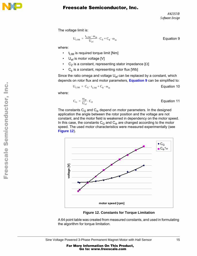
The constants CG and CΦ depend on motor parameters. In the designed application the angle between the rotor position and the voltage are not constant, and the motor field is weakened in dependency on the motor speed. In this case, the constants CG and CΦ are changed according to the motor speed. The used motor characteristics were measured experimentally (see Figure 12).
Figure 12. Constants for Torque Limitation
A 64 point table was created from measured constants, and used in formulating the algorithm for torque limitation.
ULIMtLIM ωm⋅
Uef---------------------- CZ Cφ ω⋅ m+⋅=
ULIM CG t⋅ LIM Cφ ω⋅ m+=
CGωm
Uef-------- CZ⋅=
motor speed [rpm]
volta
ge [V
]
CGCΦ*ω
Sine Voltage Powered 3-Phase Permanent Magnet Motor with Hall Sensor 15
For More Information On This Product, Go to: www.freescale.com
AN2357/D
F
ree
sca
le S
em
ico
nd
uc
tor,
I
Freescale Semiconductor, Inc.n
c..
.
Voltage Ripple Cancellation
The voltage ripple cancellation recalculates the absolute required voltage into a relative voltage, so that output voltage amplitude does not depend on the dc-bus voltage.
Equation 12
where:• Ureq is absolute voltage required by speed controller [V]• Urel is relative voltage going to sine wave generator [-]• UDC is dc-bus voltage [V]
The function has two main purposes:1. Change in dc-bus voltage does not effect torque limitation algorithm2. Jump in dc-bus voltage does not cause transient speed deviation
Field Weakening Calculation
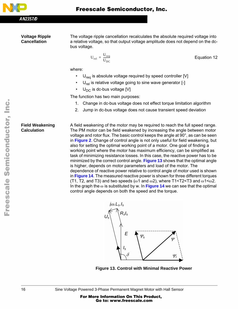
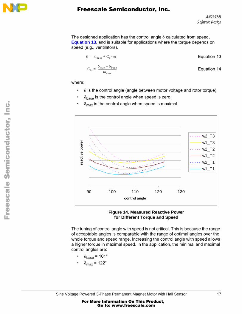
A field weakening of the motor may be required to reach the full speed range. The PM motor can be field weakened by increasing the angle between motor voltage and rotor flux. The basic control keeps the angle at 90°, as can be seen in Figure 2. Change of control angle is not only useful for field weakening, but also for setting the optimal working point of a motor. One goal of finding a working point where the motor has maximum efficiency, can be simplified as task of minimizing resistance losses. In this case, the reactive power has to be minimized by the correct control angle. Figure 13 shows that the optimal angle is higher, depends on motor parameters and load of the motor. The dependence of reactive power relative to control angle of motor used is shown in Figure 14. The measured reactive power is shown for three different torques (T1, T2, and T3) and two speeds (ω1 and ω2), where T1<T2<T3 and ω1<ω2. In the graph the ω is substituted by w. In Figure 14 we can see that the optimal control angle depends on both the speed and the torque.
Figure 13. Control with Minimal Reactive Power
UrelUreq
UDC----------=
Us
jω.Ls.Is
Ψr
Ψs Ψ
RsIs
E
Is δ
16 Sine Voltage Powered 3-Phase Permanent Magnet Motor with Hall Sensor
For More Information On This Product, Go to: www.freescale.com
AN2357/DSoftware Design
F
ree
sca
le S
em
ico
nd
uc
tor,
I
Freescale Semiconductor, Inc.n
c..
.
The designed application has the control angle δ calculated from speed, Equation 13, and is suitable for applications where the torque depends on speed (e.g., ventilators).
Equation 13
Equation 14
where:
• δ is the control angle (angle between motor voltage and rotor torque)• δbase is the control angle when speed is zero• δmax is the control angle when speed is maximal
Figure 14. Measured Reactive Powerfor Different Torque and Speed
The tuning of control angle with speed is not critical. This is because the range of acceptable angles is comparable with the range of optimal angles over the whole torque and speed range. Increasing the control angle with speed allows a higher torque in maximal speed. In the application, the minimal and maximal control angles are:
• δbase = 101°• δmax = 122°
δ δbase Cδ ω⋅+=
Cδδmax δbase–
ωmax----------------------------=
90 100 110 120 130control angle
reac
tive
pow
er
w2_T3w1_T3w2_T2w1_T2w2_T1w1_T1
Sine Voltage Powered 3-Phase Permanent Magnet Motor with Hall Sensor 17
For More Information On This Product, Go to: www.freescale.com
AN2357/D
F
ree
sca
le S
em
ico
nd
uc
tor,
I
Freescale Semiconductor, Inc.n
c..
.
Sine Wave Generation
The sine wave generation is calculated with each PWM reload interrupt, which is every 64 µs. The function
sin3p3hPIxLUT(Abate u_phase_amplitude, SWord16 phase_actual);
gets the sinus of the actual phase for all three phases from the table, and multiplies it by the phase amplitude. Resolution of the sinus is 1024 points per period and 256 points per amplitude. The function is written in assembly language to minimize execution time. The execution time is about 20 µs.
Over-Voltage Limitation
Over-voltage limitation protects the power stage during recuperation. If the required speed is lower then the actual while over voltage occurs, the required speed is increased to stabilize the dc-bus voltage. The required speed is decreased so that the dc voltage keeps to the limiting value, until the actual speed is higher than required.
CPU Reset to Turning Motor
If the CPU is reset while the motor is running, the initialization routine recognizes the running motor from the Hall sensor signal. Then, the speed of motor is calculated and PLL is synchronized with the Hall sensor signal. The voltage amplitude is estimated from the measured speed, which helps to switch-on PWM without torque surge. CPU reset always switches the application to manual control, even if the application was controlled by PC master software.
PC Master Software (Remote) Operating Mode
The drive is controlled remotely from a PC via an RS-232 physical interface. The manual control is ignored and all required values are controlled from PC.
PC master software displays the following information on a control page:• Required speed• Actual speed• RUN/STOP switch status• CLOSE LOOP/OPEN LOOP• Application status
The other variables can be viewed in the variables section.
Project files for the PC master are located in:...\applications\3ph_pm_sin\sources\pcmaster\3ph_pm_sin.pmp
Start the PC master software window’s application, 3ph_pm_hs.pmp;
If the PC master project (.pmp file) is unable to control the application, it is possible that the wrong load map (.elf file) has been selected. PC master uses
18 Sine Voltage Powered 3-Phase Permanent Magnet Motor with Hall Sensor
For More Information On This Product, Go to: www.freescale.com

AN2357/DReferences
F
ree
sca
le S
em
ico
nd
uc
tor,
I
Freescale Semiconductor, Inc.n
c..
.
the load map to determine addresses for the global variables being monitored. Once the PC master project has been launched, this option may be selected in the PC master window under "Project/Select other Map FileReload".
References
[1] Electronically Commutated Motors for Fan Applications, A. Lelkes, PCIM 2002.
[2] Design of Brushless Permanent-Magnet Motors, J.R. Hendershot and T.J.E. Miller, Magna Physics Publishing and Clarendon Press, 1994
[3] AN1917, 3-Phase Synchronous PM Motor Control with Quadrature Encoder Using DSP56F80x, P.Grasblum, Freescale 2002
[4] AN2292, 8-Bit Software Development Kit, J. Ryba, Freescale 2002
Sine Voltage Powered 3-Phase Permanent Magnet Motor with Hall Sensor 19
For More Information On This Product, Go to: www.freescale.com
AN2357/D
F
ree
sca
le S
em
ico
nd
uc
tor,
I
Freescale Semiconductor, Inc.n
c..
.
AN2357/DRev. 011/2002
For More Information On This Product, Go to: www.freescale.com