an evaluation of reed bed technology to dewater … use of reeds speeds sludge dewatering because...
TRANSCRIPT
A D-A 273 500 USACERL Technical Report EP-93/09
1 iimi1IIiiiill September 1993Appropriate Technology for Army Anaerobic Digester Sludge
US Army Corpsof EngineersConstruction EngineeringResearch Laboratories
An Evaluation of Reed BedTechnology To Dewater ArmyWastewater Treatment Plant Sludge
byByung J. Kim 93-29834Raul R. Cardenas
Satya P. Chennupati
As operator of over 100 small wastewater treatment plants(WWTPs), the Army has an interest in efficient and cost-effectivesludge dewatering systems. Many Army wastewater treatmentplants use conventional sand-drying beds to dewater sludge.However, sand drying involves costly regular removal of sludge,and sand-drying beds are vulnerable to operational problems with Tlong drying periods during wet weather and sand media clogging. ELECT E
DEC 0 8 1993Successful new technologies for sludge treatment in small-scaleWWTPs include wedgewater beds, vacuum-assisted beds, and Areed-bed systems. This study builds on a previous USACERL A1evaluation of wedgewater and vacuum-assisted bed performanceby compiling operational data from municipal and industrialWWTPs that have reed bed systems to evaluate their potential forArmy use. The use of reeds speeds sludge dewatering becausethe root systems maintain natural drainage channels throughoutthe sludge volume, and because reeds complement air drying bydrawing water into the plant for evapotranspiration. Reed bedswere found to be easier to operate and maintain than sand-dryingbeds, and to virtually eliminate the need for regular sludgeremoval. Moreover, reed beds can be simply and efficientlyretrofit to existing sand-drying beds. Because the Army has large-area drying beds that can be converted to reed bedseconomically, reed bed systems were found to have a goodpotential for use at Army WWVTPs.
Approved for public release; distribution is unlimited.
93 12 7 '049
The contents of this report are not to be used for advertising, publication,or promotional purposes. Citation of trade names does not constitute anofficial endorsement or approval of the use of such commercial products.The findings of this report are not to be construed as an officialDepartment of the Army position, unless so designated by other authorizeddocuments.
DESTROY THIS REPORT WHEN IT IS NO LONGER NEEDED
DO NOT RETURN IT TO THE ORIGINATOR
USER EVALUATION OF REPORT
REFERENCE: USACERL Technical Report EP-93/09, An Evaluation of Reed Bed Technology ToDewater Army Wastewater Treatment Plant Sludge
Please take a few minutes to answer the questions below, tear out this sheet, and return it to USACERL.As user of this report, your customer comments will provide USACERL with information essential forimproving future reports.
1. Does this report satisfy a need? (Comment on purpose, related project, or other area of interest forwhich report will be used.)
2. How, specifically, is the report being used? (Information source, design data or procedure,management procedure, source of ideas, etc.)
3. Has the information in this report led to any quantitative savings as far as manhours/contract dollarssaved, operating costs avoided, efficiencies achieved, etc.? If so, please elaboratc.
4. What is your evaluation of this report in the following areas?
a. Presentation:
b. Completeness:
c. Easy to Understand:
d. Easy to Implement:
e. Adequate Reference Material:
f. Relates to Area of Interest:
g. Did the report meet your expectations?
h. Does the report raise unanswered questions?
i. General Comments. (Indicate what you think should be changed to make this report and futurereports of this type more responsive to your needs, more usable, improve readability, etc.)
5. If you would like to be contacted by the personnel who prepared this report to raise specific questionsor discuss the topic, please fill in the following information.
Name:
Telephone Number_.
Organization Address:
6. Please mail the completed form to:
Department of the ArmyCONSTRUCTION ENGINEERING RESEARCH LABORATORIESATTN: CECER-IMTP.O. Box 9005Champaign, IL 61826-9005
REPORT DOCUMENTATION PAGE For AprovI OMB No. 0704-0188
Pubbc repooing Iuxden for tis waaclon of inorimnabon is emlifmsd to aveage I hour per reaponse. incu03 tie tbim for reviewing in lmtiutions. nmrct g existing "if sourcas.gang and meiataining tie daa needed. and compileting and reviewing the oodation of inftonnmlon. Send anmments reg•r•ing tis burden estmate or any other eue of thisollctlon of informtion, including suggestions for reducing tis burden, to Wahingon Hedquarters SeoMv ,. Direcorate tfo itoimation Opwerio and Reports. 1215 Jeflerson
Das Highway. Suit 1204. Arlington, VA 22202-4302. end to the Offioe of Management and &A". Paperwali Reducion Prod (0704-0138), Washington. DC 20503.1. AGENCY USE ONLY (Leave Bank) 2. REPORT DATE - 3. REPORT TYPE AND DATES COVERED
September 1993 Final
4. TITLE AND SUBTITLE 5. FUNDING NUMBERS
An Evaluation of Reed Bed Technology To Dewater Army Wastewater Treatment 4A162720Plant Sludge A896
TB2
6. AUTHOR(S)Byung J. Kim, Raul R. Cardenas, and Satya P. Chennupati
7. PERFORMING ORGANIZATION NAME(S) AND ADDRESS(ES) 8. PERFORMING ORGANIZATIONU.S. Army Construction Engineering Research Laboratories (USACERL) REPORT NUMBERP.O. Box 9005 TR-EP-93/09Champaign, IL 61826-9005
9. SPONSORING$MONITORING AGENCY NAME(S) AND ADDRESb(ES) 10. SPONSORING/MONITORING
U.S. Army Center for Public Works (USACPW) AGENCY REPORT NUMBER
AUTN: CECPW-FU-SBldg. 358Fort Belvoir, VA 22060-5516
11. SUPPLEMENTARY NOTES
Copies are available from the National Technical Information Service, 5285 Port Royal Road, Springfield, VA22161
12a. DISTRIBUTIONWAVAILABILITY STATEMENT 12b. DISTRIBUTION CODE
Approved for public release; distribution is unlimited.
13. ABSTRACT (Maximum 200 words)
As operator of over 100 small wastewater treatment plants (WWTPs), the Army has an interest in efficient andcost-effective sludge dewatering systems. Many Army wastewater treatment plants use conventional sand-dryingbeds to dewater sludge. However, sand drying involves costly regular removal of sludge, and sand-drying bedsare vulnerable to operational problems with long drying periods during wet weather and sand media clogging.
Successful new technologies for sludge treatment in small-qcale WWTPs include wedgewater beds,vacuum-assisted beds, and reed-bed systems. This study builds on a previous USACERL evaluation ofwedgewater and vacuum-assisted bed performance by compiling operational data from municipal and industrialWWTPs that have reed bed systems to evaluate their potential for Army use. The use of reeds speeds sludgedewatering because the root systems maintain natural drainage channels throughout the sludge volume, andbecause reeds complement air drying by drawing water into the plant for evapotranspiration. Reed beds werefound to be easier to operate and maintain than sand-drying beds, and to virtually eliminate the need for regularsludge removal. Moreover, reed beds can be simply and efficiently retrofit to existing sand-drying beds.Because the Army has large-area drying beds that can be converted to reed beds economically, reed bed systemswere found to have a good potential for use at Army WWTPs.
14. SUBJECT TERMS 15. NUMBER OF PAGES
wastewater treatment plant 44sludge dewatering systems 16. PRICE CODEreed bed technology
17. SECURITY CLASSIFICATION 18. SECURITY CLASSIFICATION 19. SECURITY CLASSIFICATION 20. LIMITATION OF ABSTRACTOF REPORT OF THIS PAGE OF ABSTRACTUnclassified Unclassified Unclassified SAR
NSN 7540-01-260-5500 Standard Form 296 (Rev. 2-80)Preal•isby ANSI Mu M-III2119-102
FOREWORD
This research was conducted for the U.S. Army Center for Public Works (USACPW), Fort Belvoir,VA, under Project 4A 162720A896, "Environmental Quality Technology"; Work Unit TB2, "AppropriateTechnology for Army Anaerobic Digester Sludge." The technical monitor was Malcolm McLeod.CECPW-FU-S.
This study was performed by the Environmental Engineering Division (EP), of the EnvironmentalSustainment Laboratory (EL), U.S. Army Construction Engineering Research Laboratories (USACERL).The USACERL principal investigator was Dr. Byung Kim. Dr. Raul Cardenas is associated withCarpenter Environmental Associates, Inc., Ramsey, NJ. Satya Chennupati is a graduate student in theEnvironmental Engineering and Science program at the University of Illinois, Urbana. Dr. Edgar D. Smithis Acting Chief, CECER-EP, and Dr. William Goran is Acting Chief, CECER-EL. The USACERLtechnical editor was William J. Wolfe, Information Management Office.
LTC David J. Rehbein is Commander of USACERL and Dr. L.R. Shaffer is the Director.
Acces•on Far
N~iS CRAM&-DTIC le.-
By ...... .............
Distributbon I
Avaxbitiy Codo;s• A'~t a: ' ,;o
Dist bp-cial
1 • QUALUflTu IizCTfD "
2
CONTENTSPage
SF 298 1FOREWORD 2
INTRODUCTION ................................................... 5Background 5Objectives 5Approach 6Scope 6Mode of Technology Transfer 6
2 OVERVIEW OF REED BED PROCESS ................................... 7Overview 7Literature Review 8
3 FINDINGS ........................................................ 10Background Data 10Plant Data 18Plant Capacity 18Bed Sizes 18Hydraulic Loading Rate 18Solids Loading Rate 22Construction Costs 24Start-up 24Operation and Maintenance 25The Role of Reed in the Beds 27Other Problems 28Plant Tolerance 28Sludge Residence Volume 28Nutrient Balance 29
4 DISCUSSION ...................................................... 30Comparison of Reed to Sand-Drying Beds 30Potential Use 33
5 CONCLUSIONS .................................................... 34
REFERENCES 34
APPENDIX: Sample Questionnaire 37
DISTRIBUTION
3
AN EVALUATION OF REED BED TECHNOLOGY TODEWATER ARMY WASTEWATER TREATMENT PLANT SLUDGE
I INTRODUCTION
Background
In terms of operations, costs, and processing, the management and handling of wastewater sludgemakes up a significant part of Army wastewater treatment. Over the years, a variety of sludgemanagement technologies have become available. An installation may choose to dewater sludge bymechanical or natural methods based on the size of its dewatering facitlies, on land availability, or on thenature of the sludge. Most U.S. Army installations practice anaerobic digestion for sludge stabilization,followed by the use of conventional sand-drying beds for sludge dewatering.
Small wastewater treatment plants, especially Army plants, commonly use sand-drying beds todewater sludge for their many advantages: they are simple in design; easy to operate; low-maintenance;energy-efficient; and relatively incxpcnsive to construct, operate, and maintain. With these systems, thesludge is simply spread over the sand-drying beds and dewatered by a combination of evaporation anddrainage.
However, sand-drying beds require long dewatering times (3 to 4 weeks), and need regular, intensivemanual labor to remove the dewatered sludge. Sand-drying beds are also vulnerable to bad weatherconditions and sometimes experience operational problems related to clogging of both the media andunderdrains.
The U.S. Army Construction Engineering Laboratories (USACERL) has been investigating improvedways to dewater sludge. Two alternatives to sand-drying identified in this effort were the use ofwedgewater beds and reed beds. A USACERL study found that wedgewater beds were most effectivewhere space is critically limited (Kim et al. 1992).
"Reed bed dewatering" is a relatively new modification to sand-drying beds that uses the commonreed (genus Phragmites) to treat wastewater sludges. The reed bed process was first used to treatwastewater (Haider 1985), and only later to dewater sludge. In this process, wastewater treatment plantsludges are applied to an actively growing stand of common reeds under controlled conditions. Thegrowing reeds derive moisture and nutrients from the sludge; over time, the rooted plants and their rootecosystem, combined with the effects of weathering, dewater the sludge and improve its characteristics.As in sand-drying beds, the sludge dries naturally, by evaporation and drainage. Reed bed technology hasbeen successfully demonstrated in the northeastern United States in sludge dewatering (U.S. EnvironmentalProtection Agency [USEPA] September 1987), and more than 50 existing reed beds are currently inoperation. This study surveyed technical information on the use of reed bed technology to establish thebaseline for using this relatively new alternative technology at U.S. Army wastewater treatment plants.
Objectives
The objectives of this study were to: (I) compile and evaluate technical information on the use ofreed beds to dewater wastewater treatment plant sludges in the United States, (2) compare the use of reed
beds to the use of alternative sludge-dewatering technologies, and (3) evaluate the potential for using reedbeds for dewatering wastewater treatment plant sludges generated at U.S. Army installations.
Approach
A literature study was done to collect relevant background information on the use of reed bedtechnology to dewater sludge. A field inspection was done of representative reed bed units to evaluateexisting reed bed operations. This information was analyzed to determine the applicability of reed bedtechnology to U.S. Army installations. Areas for further study were identified.
Scope
This report analyzed existing reed bed operations only. Investigation of the technical aspects of reedbed design and scientific principles behind reed bed operation were beyond the scope of this study.
Mode of Technology Transfer
It is anticipated that the information gained from this effort will be incorporated into an PublicWorks Technical Bulletin (PWTB), to be prepared and distributed by the U.S. Army Center for PublicWorks (USACPW), Fort Belvoir, VA.
6
2 OVERVIEW OF REED BED PROCESS
Overview
The reed bed process is an innovative process for sludge dewatering that combines the operatingadvantages of underdrained sand-drying beds with an added dewatering advantage derived from the activegrowth and activities of the common reed, genus Phragmites. A variety of stabilized sludges have beendewatered by this method, including aerobic and anaerobic sludges.
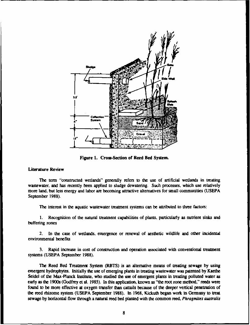
Reed beds are often constructed outdoors but may be sheltered (e.g., covered with roofs), or givenan even greater degree of environmental control in greenhouses. Often reed beds are retrofitted to existingconventional sand-drying beds. In practice, reed beds are constructed similarly to sand-drying beds.Construction begins by excavating a number of parallel, rectangular trenches of planned dimensions, whichinclude vertical sides, underdrains, and a sludge distribution system (Figure 1).
The excavated trench is lined with an impermeable liner to prevent exfiltration, and is filled withtwo sizes of gravel and a top layer of filter sand. The liner can be of any impermeable, durable material.(Several installations have employed precast Hypalon liners without any problems.) The side walls of thebed commonly consist of concrete wall of a sand-drying bed and approximately 120 cm (4 ft) of freeboardabove the concrete wall to allow for sludge accumulation. The USEPA notes that freeboard above thesand layer should be at least I m (39 in.) to provide for long term sludge storage (USEPA September1987).
While reed bed design may vary from installation to installation, depending on the local conditions,about 25 cm (10 in.) of gravel is added to cover the underdrain piping (USEPA September 1987) and thegravel is overlaid with about 10 cm (4 in.) of filter sand. Figure 1 shows optional details relating toinfluent, distribution systems and effluent collection.
Once the beds have been constructed, Phragmites reeds are planted, usually in the form of 1-ftplants or root stocks. Phragmites is well suited to this role as it is extremely tolerant of variableenvironmental conditions and has a high evapotranspiration rate. The reeds are planted atop the gravellayer, at a planting density of one plant per square foot. The bed is then flooded with water for a periodof time varying from several days to several weeks, depending on the growth rate, to facilitate reeddevelopment.
Once the reeds are established, stabilized sludge is applied to the bed at regular intervals. Whilethe sludge dries by evaporation, the growing reeds derive nourishment and moisture from the sludge, bothstabil: ing the sludge and reducing its volume (USEPA September 1987).
Unlike ordinary sand-drying beds, reed beds do not require regular removal of dried sludges. Newsludge may be layered over the previous sludge applications. However, the reeds are normally harvestedannually. The harvest is performed during the start of the plant's winter dormancy, typically using electrichedge clippers. The harvest is often taken after the first freeze, when the sludge is hard enough to walkon. Plants are cut to approximately 20 cm (8 in.) in size. The typical harvest yields about 25 tons/acre(Reed et al. 1988). It has been estimated that the sludge accumulation need only be removed from thereed beds after about 10 years of continued applications (Banks and Davis 1983a).
7
•...............
Figure 1. Cross-Section of Reed Bed System.
Literature Review
The term "constructed wetlands" generally refers to the use of artificial wetlands in treatingwastewater, and has recently been applied to sludge dewatering. Such processes, which use relativelymore land, but less energy and labor are becoming attractive alternatives for small communities (USEPASeptember 1988).
The interest in the aquatic wastewater treatment systems can be attributed to three factors:
1. Recognition of the natural treatment capabilities of plants, particularly as nutrient sinks andbuffering zones
2. In the case of wetlands, emergence or renewal of aesthetic wildlife and other incidentalenvironmental benefits
3. Rapid increase in cost of construction and operation associated with conventional treatmentsystems (USEPA September 1988).
The Reed Bed Treatment System (RBTS) is an alternative means of treating sewage by usingemergent hydrophytes. Initially the use of emerging plants in treating wastewater was patented by KaetheSeidel of the Max-Planck Institute, who studied the use of emergent plants in treating polluted water asearly as the 1900s (Godfrey et al. 1985). In this application, known as "the root zone method," reeds werefound to be more effective at oxygen transfer than cattails because of the deeper vertical penetration ofthe reed rhizome system (USEPA September 1988). In 1968, Kickuth began work in Germany to treatsewage by horizontal flow through a natural reed bed planted with the common reed, Phragmites australis
8
(Cooper et al. 1990, p 7). Moreover, German researchers found that reeds could create oxidized zoneswithin the sludge deposits that facilitate a sequence of mineralization, nitrification, and denitrification(Cooper et al. 1990, p 275) Later studies corroborated these findings (Winter and Kickuth 1985).
In addition to dewatering wastewater, reeds have been found extremely useful in drying dredgedspoils. As early as 1932 Phragmites were used as a drying agent in Holland during land reclamation ofthe Zuider Zee (Brown 1981). More recently, reeds have been used in an Army Corps of Engineersfunded study of using vegetation to dry dredged material (Biological Water Purification Inc. 1976). Thisstudy revealed that reed-planted spoil basins would sufficiently dry to walk on. Another beneficial aspectwas that the root and rhizome system of Phragmites enhanced the porosity of the dredge deposits, therebyincreasing drainage, preventing ponding, and allowing aeration.
A study in Usterbach, Germany, described the successful use of reeds in sludge treatment anddewatering, and spurred development of a working reed bed system for sludge dewatering in the UnitedStates. In Usterbach, three beds were planted (one [100 m21 control bed) to treat sludges from anactivated sludge process. In this application, the reed beds were fed with sludge for 10 years withoutremoving them, at rates of 8 to 12 cm of sludge (1 percent dry solids) every 10 to 14 days during 8 or9 months. The control bed clogged after a few months. After 8 years of feeding, 18 m of liquid sludgehad been applied to one of the beds, leaving only 36 cm of residue, yielding a volume reduction of 98percent. Such a large reduction indicates that the reduction was due not only to dewatering, but also tomineralization (Cooper et al. 1990, p 261).
Banks and Davis summarized the interaction of sludge and reed beds to process "difficult to dry"sludges (1983a). They observed that "hydroxide slimes and sewage sludge" that dry quickly form a"closed, relatively small surface that strongly resists further drying by evaporation." They noted that thegrowth of plants with a multiple root system prevented the formation of this dense, "closed" surface andthus enhanced drying and evaporation. Plant growth absorbs water into the root system, and subsequentlyreleases it to the atmosphere by transpiration. Plants most suitable for this action are those with a greatneed for water and a tolerance of changing environmental conditions.
Such plants transport oxygen to their root systems, promoting the intense biological activitydescribed in the 1980 Usterbach study. This activity establishes a rich ecosystem, which includesearthworms and a resident microflora. Banks and Davis further speculated that the plants produced "rootexudations" that were active against pathogens, and that the plants specifically showed an affinity forcadmium, zinc, manganese, and copper, a claim perhaps related to other claims of changes in variousaromatic compounds (1983a). These researchers reported that 40 percent of the effluent volume passesthrough the bed within 6 hr, and that 70 to 80 percent of the flow passes through within 2 or 3 days.During the reed's vegetative period, evapotranspiration amounts to 40 percent of the influent volume.
The 1987 USEPA Design Manual for Dewatering Municipal Wastewater Sludges describes the reedbed process as an innovative technology. The manual provides information on installation of reed beds,which includes a description of liners, underdrains, gravel and sand particle sizes, and sludge loading.Average solids loading rates specified were 17 lb/sq ft/yr for 3 to 4 percent sludge concentrations, withannual sludge accumulations of 10 cm (4 in.). At this rate of accumulation, sludge is removed at the endof a 10-year cycle, along with the sand layer. The beds are taken out of operation 6 months prior toevacuation to allow time for the sludge to mineralize and for pathogens to be destroyed. This downtimemakes multiple beds necessary. The USEPA also reports that the major advantage of the reed bed systemis that it requires little maintenance in the way of sludge removal and bed cleaning. The majordisadvantage is the need for annual reed harvesting. The USEPA also notes that the resulting annual reedharvest volume, along with 10-year remaining sludge volume, is still less than the volume requiringdisposal during 10 years of a conventional sand-drying bed operation.
9
3 FINDINGS
Background Data
Questionnaire
To define, gather, and focus relevant information and data needs, a list of reed bed sludge treatmentinstallations was compiled and a questionnaire was developed. The questionnaire was mailed to 32 knownreed bed operations in 1990, including recently discontinued facilities. An additional 12 new plants withreed bed operations were contacted in 1992. The Appendix to this report contains a copy of the samplequestionnaire.
The questionnaire was divided into seven areas of inquiry:
1. Design data2. Construction costs3. Operation and maintenance4. Reed bed performance5. Startup data6. Replanting data7. General information relating to reed bed performance.
The goal of the questionnaire was to form the basis for data collection to take place during laterfield visits, and thereby to obtain as much information as possible for evaluation. To extract goodresponses, the respondents were encouraged to answer only the questions that could be readily answered,and the authors helped elicit answers to more difficult questions at the time of the site visit. Researchersfollowed up by telephone to clarify or supplement the information gathered by questionnaire interview.
In all, 14 of the initial (1990) questionnaires and 10 of those sent in 1992 were returned to theauthors completed to various degrees. The questionnaire formed the basis for the site visit queries thatwere made during interviews with the wastewater treatment plant persoruiel. As they were received, thequestionnaires were reviewed, results were summarized, and as required, followed up by telephone calls.
Site Visits
Six site visits and interviews were conducted at reed bed facilities in New Jersey. The plantoperators and/or managers were interviewed in an attempt to obtain available information regarding thereed bed design criteria, construction costs, operation and maintenance requirements, costs and bedperformance and closing and replanting data. Table 1 lists the reed bed facilities evaluated for this study.Data was taken on a total of 24 facilities; 6 were visited.
Engineering Evaiuation
Based on the gathered data, reed bed performance was evaluated by comparing it to conventionalmethods, i.e., sand-drying beds. The evaluation was formatted to be similar to the questionnaire; thecategories used to compare the reed bed system with conventional sludge dewatering were:
1. Design criteria (including solids loading rate)2. Cost of construction/implementation3. Operation and maintenance
10
Table I
Reed Bed Plants Studied
Installation Location
Reed bed plants studied, but not visited:Adamstown Wastewater Treatment plant Adamstown. PABally Borough Bally. PABerks Montgomery Municipal Authority Gilbertsville. PABethel Wastewater Treatment Plant PlantBethel. MEBorough of Highstown Wastewater Treatment Plant Highstown. NJBorough of Royersford Royersford. PAEllsworth Pollution Control Facility Ellsworth, MEFleetwood Sewage Treatment Plant Fleetwood, PAGordon Wastewater Treatment Plant Potsville, PALeesport Borough Authority Leesport. PAMyerstown Elco Wastewater Treatment Plant Myerstown. PANorthern Lancaster Co. Authority Denver. PAOld Bridge Township Board of Education Old Bridge. NJSaxton's River Wastewater Pollution Control Facility Saxton's River. VTSchwenksville Borough Authority Plant Schwenksville, PATopton Sewage Treatment Topton. PAWabash WWTP Wabash. INWallingford Fire District #lWastewater Treatment Plant Wallingford. VT
RWed bed plants studied and visitedBeverly Sewerage Authority Beverly, NJE.R. Johnstone Training and Research Center Bordentown. NMalboro Development Center Malboro. NJMilitary Ocean Terminal Bayonne. NJRiverton Sewage Treatment Plant Riverton, NJSchooley's Mountain Sewage Treatment Plant Long Valley. NJ
4. Type of sludge5. Winter conditions6. Sludge residue volume.
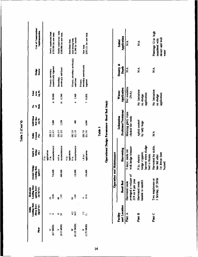
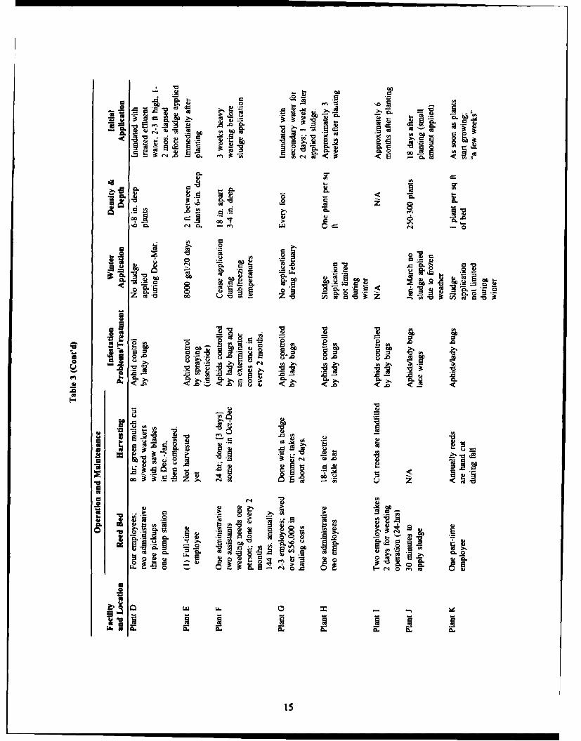
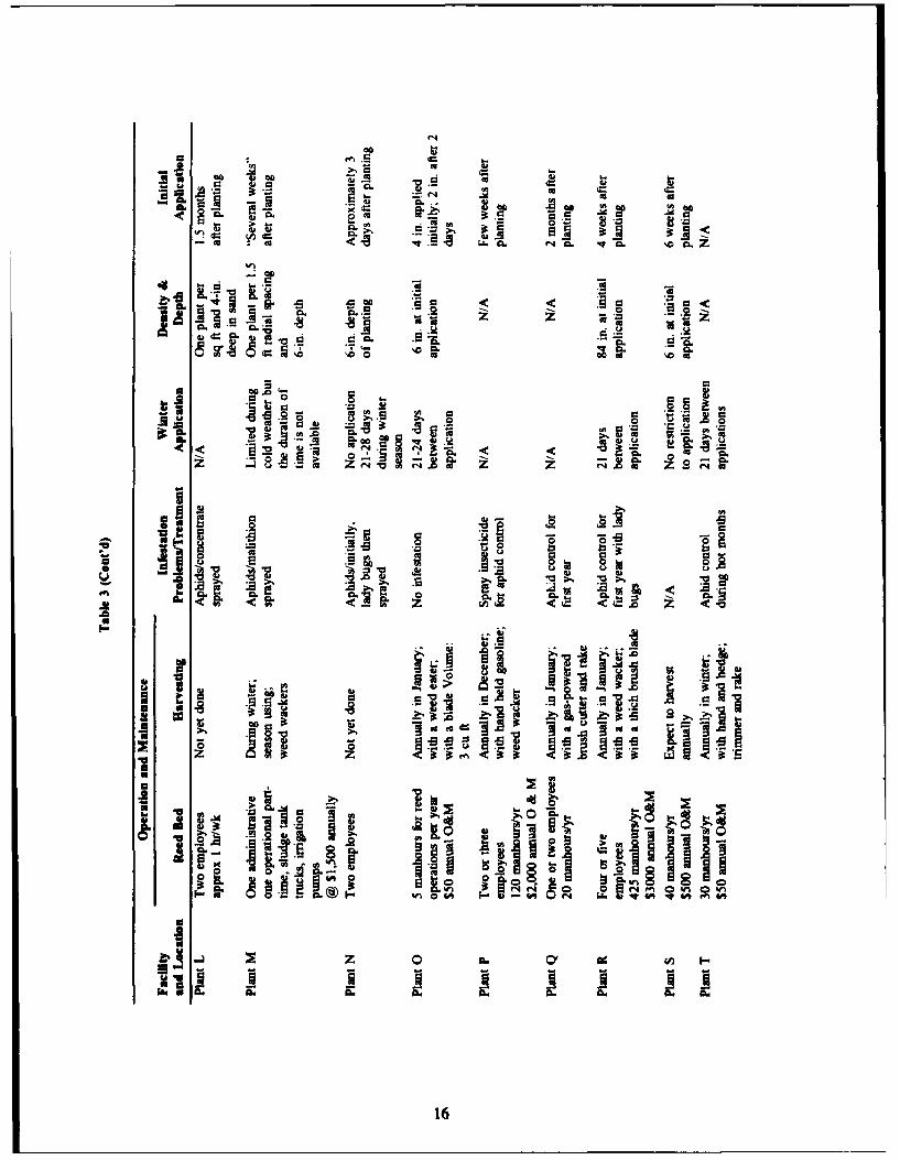
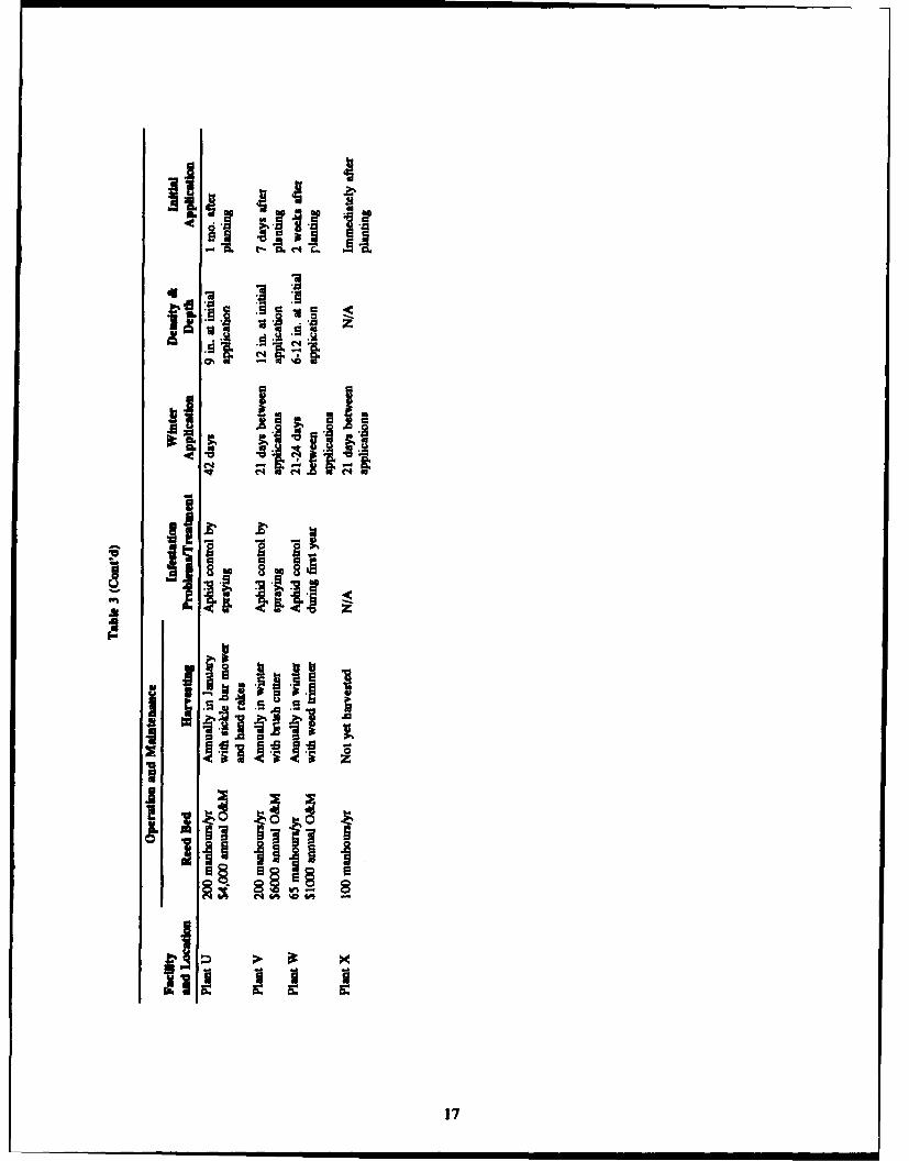
These comparisons were compiled and are tabulated in Chapter 4. Tables 2 and 3 list theengineering and operational design parameters for each investigated reed bed facility:
I. Solids loading rate2. Sludge loading rate3. Annual sludge loading rate4. Loading rate5. Sludge depth6. Solids content7. Bed sizef/number of beds8. Source of sludge9. Cost of construction/implementation10. Operation and maintenance11. Infestation problems/treatment12. Winter application13. Density and depth14. Initial application.
11
a-� a�
*
Fl I I*u .( *� C it- 0*� .(e �S.., -a a a:1 �o
a� .-.
'.5
N
� � �0 N NN : N e�. �. �. � �ga C� C
R
-� -. - A. �.§ � S -
'0 00
00a
v2 - * 00 '0 a
I 00 0 0 e - ea air � :Si - - S
00
T �" - ,.,� 00 Z -
Ia a- a
z a - V a
00 In
0 �
0 *1Iift -� 5 0 B
*
ii �Kgz z.- ,,.� .5,.� -, In�.Iiu .. - -� - A
if�'0 V'.e-. 50, 00t* ENif- 0 InIN
In U
� V�Tu a'� �a
IW 0 Z L -
:1*1
12
1 '1 Ja. .. Z,
C6° to • = =+ I - [ I+
00,,o
U U B,,, i iP
j•J A. _. A+ _.
13
AAr=
41
a-
7 53
'C C '074>o Zo
0 ao
14
f0n an
~00 > 0
<E<
49
00 0
-2 001 A >0,
00
.~. 1.
cc 4
> th
CL. .99
4 L 5-. ME
00
z 00
Is 0
cL ~ cn
wo.z Zeme > -lo~~
Is.I~ ~ .it
S>
'a 9L A.
16~
d I I
4 117
Plant Data
Most of the earliest research on reed beds was done in Germany. However, there were no reed bedoperations in the United States until the late 1980s. The most commonly used reed in the United Statesis Phragmites, which is an extremely tolerant plant as noted in the literature and by the USEPA.
The surveyed reed dewatering beds were fed with either aerobic stabilized sludge or anaerobicdigested sludge. Of the facilities surveyed, 14 fed aerobic stabilized sludge to the reed beds; 7 fedanaerobic digested sludge; and 2 fed primary Imhoff sludge.
Most of the reed beds were located in the northeastern United States (New Jersey, Pennsylvania,Maine, and Vermont). The oldest wastewater treatment facility in the United States is in New Jersey, withan operating history of 8 years. Most of the other facilities were relatively new. Table 4 lists the 47currently operating treatment facilities. The increasing number of facilities suggests that reed beddewatering is becoming recognized as an effective and efficient sludge-dewatering method.
Plant Capacity
Of the facilities dewatering aerobic stabilized sludge, the maximum plant capacity (plant S) was 0.4MGD (million gal/day) with a total reed bed area of 21,600 sq ftk and an annual sludge loading rate of1,080,000 gal/yr. The minimum plant capacity (plant W) was 0.125 MGD with a total reed bed area of2400 sq ft and an annual loading sludge rate of 120,000 gal/yr.
Of the facilities dewatering anaerobic digested sludge, the maximum plant capacity (plant X) was2.75 MGD with a total reed bed area of 42,028 sq ft and an annual sludge loading rate of 154,000 gal/yr.The minimum plant capacity (plant R) was 0.54 MGD with a total reed bed area of 3500 sq ft and anannual sludge loading rate of 47,000 gal/yr.
Bed Sizes
Most of the surveyed reed bed facilities were retrofitted from existing sand beds. The majormodification was the addition of freeboard to accommodate increasing sludge layers.
The largest reed bed facility (plant S) dewatering aerobic stabilized sludge has a total bed area of21, 60 0 sq ft (4 beds each of 5400 sq ft) and the smallest facility (plant C) has a reed bed area of 1600sq ft (2 beds each of 800 sq ft.)
The largest reed bed facility (plant X) dewatering anaerobic digested sludge has a total reed bed areaof 42,028 sq ft (7 beds each of 6004 sq ft) and the smallest facility (plant B) has a reed bed area of 1800.sq ft (2 beds each of 900 sq ft).
Hydraulic Loading Rate
Figure 2 shows the correlation between the percent solids content and actual hydraulic loading foraerobically stabilized and anaerobically digested sludge. Table 5 gives hydraulic loading data.
18
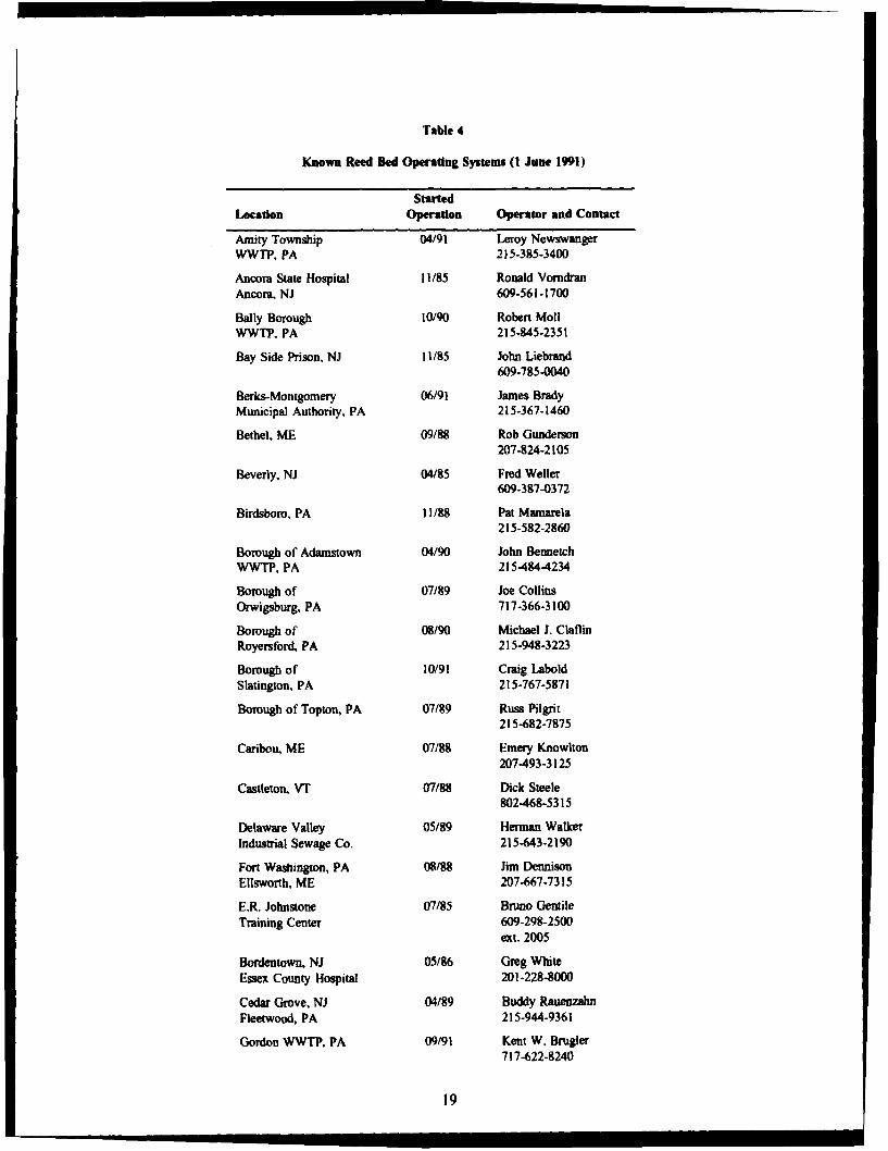
Table 4
Known Reed Bed Operating Systems (1 June 1991)
StartedLocation Operation Operator and Contact
Amity Township 04/91 Leroy NewswangerWWTP, PA 215-385-3400
Ancora State Hospital 11/85 Ronald VorndranAncora. NJ 609-561-1700
Bally Borough 10/90 Robert MollWWTP, PA 215-845-2351
Bay Side Prison, NJ 11/85 John Liebrand609-785-0040
Berks-Montgomery 06/91 James BradyMunicipal Authority. PA 215-367-1460
Bethel, ME 09/88 Rob Gunderson207-824-2105
Beverly, NJ 04/85 Fred Weller609-387-0372
Birdsboro, PA 11/88 Pat Mamarela215-582-2860
Borough of Adamstown 04/90 John BennetchWWTP, PA 215484-4234
Borough of 07/89 Joe CollinsOrwigsburg, PA 717-366-3100
Borough of 08/90 Michael J. ClaflinRoyersford, PA 215-948-3223
Borough of 10/91 Craig LaboldSlatington, PA 215-767-5871
Borough of Topton, PA 07/89 Russ Pilgrit215-682-7875
Caribou, ME 07/88 Emery Knowlton207-493-3125
Castleton. VT 07/88 Dick Steele802-468-5315
Delaware Valley 05/89 Herman WalkerIndustrial Sewage Co. 215-643-2190
Fort Wastungton, PA 08/88 Jim Dennison
Ellsworth, ME 207-667-7315
E.R. Johnstone 07/85 Bruno GentileTraining Center 609-298-2500
ext. 2005
Bordentown, NJ 05/86 Greg WhiteEssex County Hospital 201-228-8000
Cedar Grove, NJ 04/89 Buddy RauenzahnFleetwood, PA 215-944-9361
Gordon WWTP, PA 09/91 Kent W. Brugler717-622-8240
19
S.. . . . • , i i i i i i i i i i i ii ii
Table 4 (Cont'd)
StartedLocation Operation Operator and Contact
Greencastle, IN 11/89 Charlene Nicholas317-653-3394
Leesport Borough 05/90 Timothy J. Locker
Authority WWTP, PA 215-926-2060
Maidencreek, PA 11/89 Eric Burkett215-926-4140
Malboro Development 04/86 Bill SandowCenter 201-946-8100Malboro. NJ ext. 2634
Military Ocean Terminal 04/84 Hans BergerBayonne, NJ 201-823-7727
Myerstown-Elco WWTP, 10/90 Larry M. FairPA 717-866-5826
Northern Lancaster 09/90 Tim MyersCo. Authority, PA 215-445-7553
Old Bridge. NJ 06/85 Julius LoganBoard of Education 201-360-4507
Randolph. VT 06/88 Paul Stratton
802-728-9079
Robeson. PA 04/90 Dean Miller717-626-2172
Saxon's River, VT 05/86 Budd Carle802-869-2725
Schwenksville Borough 05/91 Barry LudwigAuthority WWTP, PA 215-287-7772
Seal Harbour, ME 05/87 Jim Pelletier207-276-5544
Shoemakersville. PA 05/89 Dave Smith215-562-2128
Sinking Spring, PA 05/89 Dave Miller215-678-7223
Southold, NY 12/86 Ray Jacobs516-734-5211
Sunapee, NH 05/88 Jim Leland603-763-2121
Terre Hill Borough, PA 05/89 Bob Rissler215-445-6248
U.S. Army, Fort 11/89 James EvansCampbell 502-798-3122
U.S. Navy Group 06/88 Tom SeveranceSecurity 207-963-5534Winter Harbour. ME
Wabash WWTP. IN 09/91 Vincent J. Bauco
219-563-2941
20
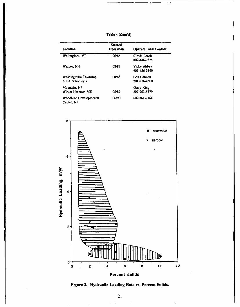
Table 4 (Cont'd)
StartedLocation Operation Operator and ContactWallingford, VT 06/86 Clovis Leach
802-446-2325
Warner, NH 08/87 Vicky Abbey603-456-3890
Washingtown Township 08185 Bob GannonMUA Schooley's 201-876-4500
Mountain, NJ Gerry KingWinter Harbour, ME 05/87 207-963-5579
Woodbine Developmental 06/90 609/861-2164Center, NJ
81
o anaerobic
0 aerobic
6
I-E
"o 4o
2-
0
0 2 4 6 8 10 12
Percent solids
Figure 2. Hydraulic Loading Rate vs. Percent Solids.
21
Table 5
Loading Data
Hydraulic Loading Rate Solids Loading RatePlant %Solids m/yr lb/sq ft/yr
Anaerobic digested sludgeB 2 0.42 2.6M 3 0.81 5.0Q I0 0.30 5.7R 5 0.55 5.6U 5 0.98 9.7X 6 0.16 12.3
Aerobic stabilized sludge 3.63 14.9D 2 2.26 9.3P 2 7.30 14.9F I 0.70 6.0G 4 5.20 21.3J 2 2.12 21.7K 5 3.38 17.2L 2.5 1.61 3.3N 1 1.91 9.20 2.4 1.22 4.0P 1.6 2.03 7.3S 1.75 1.07 3.3T 1.5 1.95 8.0V 2.25 2.03 6.2W 1.5
Of the facilities dewatering aerobic sludges, the maximum loading (plant F) was 7.3 mI/m 2/yr (7.3m/yr) (179 gal/sq ft/yr) and the minimum loading rate (plant G) was 0.73 m3/m2/yr (0.73 m/yr) (17.9gal/sq ftyr). The maximum loading rate for the facilities dewatering anaerobic digested sludges (plantU) was 0.98 mI/m 2/yr (0.98 m/yr) (24 gal/sq ft/yr) and the minimum (plant X) was 0.16 m3/m 2/yr (0.16m/yr) (4 gal/sq ft/yr).
Figure 2 shows yearly average operational hydraulic loading range on the reed beds. Hydraulicloading appears to be insensitive to solids content in the sludge. The hydraulic loading rates for anaerobicsludge are much lower compared to that of aerobic sludge. One hypothesis is that the evapo-transpirationof reeds can be higher for aerobic sludge than anaerobic sludge.
It is critical to develop logical hydraulic loading criteria to implement this technology at Armywastewater treatment plants.
Solids Loading Rate
Figure 3 depicts a correlation between the percent solids content and the actual annual solids loadingfor aerobically stabilized and anaerobically digested sludge. Table 5 provides solid loading data.Although aerobic sludge has lower percent solids, its solid loadings are much higher than anaerobicsludge. It was also noted that about 70 percent of data points arc within the dotted boundary between 12.3and 2.6 lb/sq ft/yr.
22
30
N anaerobic
o aerobic
20"
CM4
010-
S10
I I I I .
0 2 4 6 8 10 12
Percent solids
Figure 3. Solids Loading vs Percent Solids.
Of the beds dewatering aerobic stabilized sludge, the maximum solids loading rate (plant K) was106 kg/m 2/yr (21.7 lb/sq ft/yr) and the minimum (plants NT) was 16 kg/m 2/yr (3.3 lb/sq ft/yr). Of thebeds dewatering anaerobic digested sludge, the maximum solids loading rate (plant X) was 60 kg/m2/yr(12.3 lb/sq ft/yr) and the minimum (plant B) was 13 kg/m2/yr (2.6 lb/sq ftlyr).
Figure 3 shows the solids loading rate vs. the percent solids. The solids content of aerobic sludgehas a small range (I to 5 percent) whereas that of anaerobic sludge has a wide range (2 to 10 percent(Table 5). Figure 3 shows that, for aerobic sludge, the solids content of the sludge is low whereas the
23

solids loading rate is very high. On the other hand, for anaerobic sludge, the solids content of sludge isquite high whereas the solids loading rate is not as high as the serobic sludge.
Figure 3 depicts yearly average operational solids loading rate on the reed beds at each specificplant, given the type of sludge and solids content of the influent sludge to be dewatered.
By comparison, in 1987, the USEPA reported that the average solids loading rate for 16 operatingfacilities in New Jersey, New York, and North Carolina was about 81 kg/m2/yr (17 lb/sq ft/yr), a figureUSEPA noted to be on the lower end of the loading rates fo, conventional sand-drying beds (USEPA,September 1987).
The factors that may affect solids loading rate include the weather conditions (summer/winter), typeof sludge, percent solids, number of beds in operation, area of beds, and hydraulic loading.
It is critical to develop logical solids loading criteria to implement this technology at Armywastewater treatment plants.
Construction Costs
Some of the surveyed facilities were able to provide the costs for retrofitting reed beds into existingsand beds. Most of the facilities were retrofitted from existing sand-drying beds. Retrofitting costs areespecially relevant to the Army because its installations already operate sand-drying beds, which can beretrofitted easily.
Of the facilities that provided costs of retrofit, the highest cost incurred was $83,000 (plant M) for10 beds (total area 9,000 sq ft), which is $1 00/m2 ($9.30/s fit). The least cost incurred was $1,000 (plantW) for 6 beds (total area 2,400 sq ft), which is $5.0/m 2 ($0.45/sq ft).
However, some of the newly constructed reed beds were expensive to build. The highest costreported for the new construction was $750,000 (plant U) for 6 beds (total area 30,000 sq ft), which was$269/M2 ($25/sq ft).
None of the facilities could provide cost data for the construction for the initial sand-drying beds.The economic factor in the retrofit was the primary cost for reed acquisition, planting, addition offreeboard to allow for sludge accumulation, and other retrofitting such as plumbing, filter media, liners,and underdrains.
Start-up
After construction, the beds are evenly graded and the reed stock is planted. Phragmites is usuallyobtained from a commercial grower of a nearby wetland, and the reeds are usually planted during thegrowing season. Normally the root stock (I-ft plant) is planted in the beds using a 30-cm (1-ft) centerspacing between plants. The USEPA also reported similar results when reed stocks were planted at 30-cm(1-ft) centers on a gravel layer, to a depth of about 10 to 15 cm (4 to 6 in.).
After initial planting, the beds are flooded with water, maintained, and allowed to enter a vigorous,normal growth phase before sludge is applied. Usually the establishment of a healthy reed bed standrequires several weeks of growth. The study results have shown that the time elapsed between the initialplanting and the initial sludge application varied considerably due to weather conditions. Some of the
24
plants (plants K, M, P, and R) reported that only a "few" or "several" weeks elapsed after planting, whileothers (plants E, N, and X) reported that they had applied sludge immediately after planting. Somefacilities (plants D, Q, and U) waited I to 2 months before sludge application. The USEPA reports thatthe beds are usually flooded with water to a depth of about 10 cm (4 in.) for several weeks to encourageplant development, and that sludge is not applied until the plants are well established (September 1987).
Operation and Maintenance
Sludge Application and Monitoring
After the reeds have established, the treated sludge, usually ranging from 0.5 to 7 percent solids, isapplied in multiple layers, on average ranging from 5 to 10 cm (2 to 4 in.) per bed. Sludge applicationranged from weekly to bimonthly loadings. Most often, dosing to the beds is rotated among the beds.
Unlike the sand-drying beds, the previously applied and dewatered sludge is allowed to remain onthe bed, and new layers of sludge are applied directly on top of the old ones. The root system of thePhragmites allows vertical pathways for the water to drain through. Therefore, subsequent sludge layerswill be dewatered via these passageways. However, recent data indicate that the underdrainage isconsiderably less than what was expected. The facilities reported that the underdrainage would last fora day or two after the sludge application. Most of the facilities needed an employee to regulate the sludgeapplications. This employee would also visually assess the beds for possible problems such as weed orinsect (aphid) infestations, and collect sludge samples. as required.
Some of the facilities were required to monitor the sludge applied to the beds through regular testingprior to application. New Jersey requires several forms to be filled with tested parameters, includingpercent solids, percent volatiles, pH. biological oxygen demand (BOD), EP Toxicity (now toxicitycharacteristics leaching procedure [TCLP]) and coliform counts. Some facilities have reported testing inNew Jersey and that their results were within the specified standards. Some operators went beyondrequirements, and reported testing their sludge even after application to the beds; however analysis of post-application test data and results was beyond the scope of this study.
Sludge application and visual monitoring varied in the length of time needed, although it is not atedious process. At one of the facilities, this operation, including sludge sampling 5 days/week, requiredabout 30 minutes to I hr/day.
Once sludge has been applied to the reed beds, minimal attention is required until the next sludgeapplication. Unlike sand-drying beds, sludge removal is not required on a regular basis. The USEPAreports that this aspect of the reed beds makes it a powerful tool compared to conventional sand-dryingbeds (September 1987). Both the plant operators and the reed suppliers predict that the sludge can remainon the beds for approximately 10 years. USEPA (September 1987) also estimates a 10-year cycle for thereed beds in operation before the sludge is removed from the beds.
Harvesting
Once a year, usually during the late fall or winter, the reeds must be harvested from the beds. Someof the reed bed personnel prefer to carry out this operation when the beds are frozen. The survey resultsshow that the time required for harvest ranges from 1 to 3 days, depending on the bed size, method used,and the number of beds to be harvested. Normally, two workers are required, one to cut and the otherto collect and remove the reeds. The USEPA recommends the annual harvesting of reeds when the plantsare dormant, but before they shed leaves (September 1987).
25
Harvesting does not require any specialized or heavy mechanical equipment. It is normallyperformed manually with hedge clippers, sickles, or a mechanical "weed whacker" (a gasoline poweredportable saw with a 230-mm x 1.8-mm blade). Similar to the homeowner's weed whacker, it is operatedwith an extended handle to cut the reeds to a height of about 20 cm (0.7 ft). The harvested reeds maythen be disposed of by hauling to local landfills, composting, or burning. Since harvesting is the majormanpower requirement and disposal of harvested reeds is no simple problem, other alternatives includingno-harvest and on-site disposal should be considered.
Weeding
The only major operation regarding the maintenance occurs during harvesting, when any weeds thathave grown among the reeds are removed. Weeding may not be necessary at every facility, especiallyafter the first growing season. While plants are being established, and before new growth occurs, it maybe necessary to weed out tomato plants (Lycopersicon Esculentum). After the reeds have becomeestablished, Phragmites generally forms a dense stand that precludes the growth of other species.
The weeding operation requires from I to 3 days and is usually carried out by hand using 1 to 3persons, depending on the density of weeds. Two facilities recorded the longest time-about 200 manhoursper year-on overall maintenance. Another plant, at the extreme upper end of the weeding requirement,expends about 144 manhours per year, whereas a small plant estimates about 2 hr per bed, or a total of1 or 2 days for the 8 beds at the facility. The extensive amount of weeding required at the facility (144hr) is attributed to the annual reed die-off. The heat generated at this greenhouse-enclosed facilityprohibits the formation of the usual dense Phragmites stands. Other weed species found at this facilityare Polygonum Spp. and Panicum Dichotomiflorum (zig-zag grass). Another facility that had discontinuedthe reed bed system, reported problems with morning glory vines (family Convolvulaceae) choking thePhragmites.
Sludge Removal
According to the operators and the reed suppliers, the reed beds should be fully functional for aperiod of 10 years, although this figure could vary between 6 and 10 years. The USEPA estimates thecycle time as 10 years (September 1987). However, at the time of this survey. no facility has operateda reed bed for a full 10-year cycle.
Of the existing U.S. facilities, 6 are reported to have a maximum of 7 to 8 years of operating historywith reeds. The earliest evacuation was expected to occur in 3 to 4 years. However, the reeds have beenfully functional according to the operators' evaluation.
Sigmatron Biological, Inc. recommends that when the sludge accumulation reaches 90 cm (3 ft), thereed beds should be entirely evacuated (including the upper layer "filter" sand removal and replacement)and new reeds planted. To reduce pathogens, it is further recommended that the facility stop sludgeapplication about 6 months before evacuating the existing beds. The USEPA also recommends that, if -a bed is to be cleaned, sludge applications should be stopped in the early spring and the sludge residueand sand removed by winter (1987). Since no operational data is available associated with the USEPA'snew sludge regulations (Part 503), more research is needed in the pathogen reduction on reed beds.
Winter Operations
The reeds' dormancy during winter affects the rate at which water is taken up for plant processes.During the freezing months, the sludge application is normally stopped and reeds are harvested.Phragmites is considered to be an extremely tolerant plant that can withstand a wide range of
26

temperatures, the most desirable temperature range being 12 to 23 'C (USEPA 1988). The USEPAestimates that New Jersey facilities experience total annual downtime due to bad weather of only 20 to30 days (1987). Survey results show that some facilities do not slow down operations during the wintermonths, while others reduce their sludge application (usually December to March). At one plant, theoperator reported that sludge is hauled during the colder winter months, depending on the weather. Notethat freezing and thawing of sludge is itself a sludge-dewatering technique (Martel 1988). More researchneeds to be done as to how effectively reed beds will function in combination with freezing and thawing,especially during the winter months.
Replanting
Survey results revealed that only three facilities reported a need to replant. One facility reported that50 percent of the reeds initially planted failed to survive. The limited reed survival at this facility wasattributed to the excess heat generated in the greenhouse. However, after the removal of several glasspanes from the greenhouse and the installation of two fans, the survival rate rose to 90 percent. Atanother facility, one bed was entirely replanted while three others required partial replanting. The primarycauses of the reed die-off in this instance was aphid infestation and summer heat. Another facilityreported that their reeds had to be replanted four times before they established properly. This facility'slast replanting (Spring 1989) proved to be the most successful. The reed survival at this facility wasattributed to a program of watering with an irrigation system, heavy fertilization, and a delay in theapplication of sludge for several weeks.
The Role of Reed in the Beds
The use of reed beds in sludge dewatering combines the action of conventional sand-drying bedswith the effects of reed in a constructed wetland. The plant's great demand for water enables a furthersludge desiccation, which results in a residue with a high solids content. For the whole process to befunctional, the use of rooted vegetation in the reed bed is a key component. The presence of active plantscapable of growing in sludge affects the hydraulic functions of the system, and the associated sedimentecosystem and transformations that occur in the sludges.
The reeds' root system creates a permanent series of channels that drain moisture from the overlyingsludge layers. This is partly physical (resulting from the reeds' major and minor root network) and partlymicrobiological (resulting from the activity in the ecosystem that develops in association with the rootsystem). The reeds possess the ability to transmit oxygen from the leaves to the roots, creating aerobicmicrosites (adjacent to the roots) in an otherwise anaerobic environment. which assist in the stabilizationand mineralization of sludge (USEPA September 1987). Research is needed to compare aerobic sludgeto anaerobic sludge in terms of reed growth and chemical characteristics of sludge to explain this process.
The microbial system associated with the reeds, for example, apparently maintains micro-drainagechannels near and associated with the root system, clear of the characteristic obstructive films typical ofair-dried sludge, which minimizes drainage (Banks and Davis 1983a). The plant activity, in effect.promotes drainage and water absorption by the root system. While some of the water drains freely, aneven larger portion is drawn up by the roots to the leaf system to be transpired to the atmosphere. Awater mass balance should be constructed to investigate the dewatering capability of reed beds.
Of the facilities studied, eight reported periodic testing of the sludge in the reed beds. Results wereonly available from one Vermont facility. Testing at this facility was done before a planned prematuresludge removal; the sludge was to be removed after only 3 years of applications due to reed die-off andfailure. After evacuation, the beds will be replanted. EP Toxicity tests (as of September 1989) indicate
27
that the sludge fell within the allowable Vermont EP Toxicity levels for all parameters except lead. Thecalculated EP Toxicity value for lead was 7.66 mg/kg dry weight sludge, as compared with the acceptedlimit of 2.66 mg/kg. Further research should be done to explain the mass balance of heavy metals thatenter the reed bed. In all, more agronomical research would provide a better knowledge andunderstanding of reed beds.
Other Problems
Most of the facilities reported that the reeds were frequently and severely infested with aphids,especially during the summer months. Eight facilities used a combination of lady bugs and insecticideannually to control infestation, while remaining facilities were using only lady bugs and three using onlyinsecticide. In this study, two facilities (plants 0 and X) reported no problems with aphids. Some of theplants also needed to weed their beds periodically to eliminate the opportunity for the weeds to stiflegrowth of the reeds.
Additionally, visits to the facilities with reed beds enclosed in greenhouses indicated that thegreenhouse environment generates severe heat and drought stress on the reeds, making it difficult for goodreed establishmenL
During the field visits, several operators voiced their concern that sludge disposal could become aproblem if future regulatory standards prohibit the disposal of sludge in landfills.
Plant Tolerance
Phragmites can normally tolerate a wide range of temperatures, but desirable growth temperaturesrange from 12 to 23 °C (53-73 OF) (USEPA 1988). The reeds are sensitive to extreme heat and thereforethey should be cultivated in an ambient environment.
In addition to temperature variations, Phragmites tolerates a variety of environmental conditions,which explains its worldwide distribution. According to estimates, reeds can tolerate a pH range of 2.0to 8.0 and a maximum salinity of 45 ppt (pans per thousand) (USEPA 1988). Phragmites does requirea wet, but not a flooded, environment because the plant will not tolerate extended inundations of over two-thirds of the plant height. Phragmites will not tolerate shaded conditions (Pompeo 1984). Furtherresearch regarding the phytotoxicity of reeds is needed to determine the loading limitations of these beds.
Sludge Residence Volume
Since no plant has sufficient data to complete a recommended 10-year cycle for sludge removal, itis hard to determine long term sludge residue volume. However, many facilities have recently startedoperation and the operators provided an approximate depth of sludge accumulation at the time of thestudy. Plants J, L, and B reported sludge accumulations of 51, 46, and 61 cm (20 in./3 yrs, 18 in./1 yr,and 24 in./4 yrs) respectively. Some of the newer plants (R, P, and V) reported sludge accumulations of41 cm, 46 cm, and 20 cm (16 in./1.5 yrs, 18 in./1 yr, and 8 in./l yr) respectively to date. However, thedepths were estimates for a short time period and do not form a good basis for estimating the long-termsludge residue volume Another facility in New Jersey reported that the sludge at the bottom of the reedbeds was a dark, loamy compost-like substance with an earthy smell. Further scientific research may beneeded to thoroughly understand the factors affecting sludge volume reduction on the beds; for example,carbon/nitrogen ratio, micro-organisms' capability to desiccate the sludge, and weathering effect.
28
Nutrient Balance
Some of the facilities had laboratory analyses performed on their sludge, for nutrients and metalcontents. However, they did not provide any quantitative data for our study.
A comparison between the nutrients in sludge versus the nutritional needs of the reeds has not beenaccurately determined. However, reed growth at various installations was observed to be tall and dense,i.e., in a healthy growth phase. Salinity (Max. 4.5 percent) conditions also affect the reed height andabundance. In addition, Phragmites is known to be important in nitrogen recycling (Cooper et al. 1990).The widespread nature of Phragmites indicates that, while nutrient levels may affect plant quality, theydo not appear to inhibit plant survival. However, more nutrient balance information will help to accuratelydetermine the solids loading criteria.
29
4 DISCUSSION
Comparison of Reed to Sand-Drying Beds
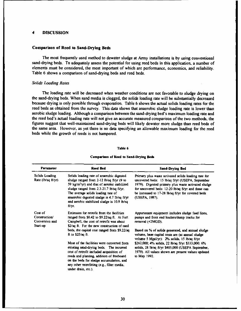
The most frequently used method to dewater sludge at Army installations is by using conventionalsand-drying beds. To adequately assess the potential for using reed beds in this application, a number ofelements must be considered, the most important of which are performance, economics, and reliability.Table 6 shows a comparison of sand-drying beds and reed beds.
Solids Loading Rates
The loading rate will be decreased when weather conditions are not favorable to sludge drying onthe sand-drying beds. When sand media is clogged, the solids loading rate will be substantially decreasedbecause drying is only possible through evaporation. Table 6 shows the actual solids loading rates for thereed beds as obtained from the survey. This data shows that anaerobic sludge loading rate is lower thanaerobic sludge loading. Although a comparison between the sand-drying bed's maximum loading rate andthe reed bed's actual loading rate will not give an accurate measured comparison of the two methods, thefigures suggest that well-maintained sand-drying beds will likely dewater more sludge than reed beds ofthe same area. However, as yet there is no data specifying an allowable maximum loading for the reedbeds while the growth of reeds is not hampered.
Table 6
Comparison of Reed to Sand-Drying Beds
Parameter Reed Bed Sand-Drying Bed
Solids Loading Solids loading rate of anaerobic digested Primary plus waste activated solids loading rate forRate (lb/sq ft/yr) sludge ranged from 2-12 lb/sq ft/yr (9 to uncovered beds: 15 lb/sq ft/yr (USEPA, September
59 kg/m2/yr) and that of aerobic stabilized 1979). Digested primary plus waste activated sludgesludge ranged from 2.3-21.7 lb/sq ft/yr. for uncovered beds: 12-20 lb/sq ftlyr and these canThe average solids loading rate of be increased to 17-28 Ib/sq ftlyr for covered bedsanaerobic digested sludge is 4.7 lb/sq ft/yr (USEPA, 1987).and aerobic stabilized sludge is 10.9 lb/sqft/yr.
Cost of Estimates for retrofit from the facilities Appurtenant equipment includes sludge feed lines.Construction/ ranged from $0.42 to $9.22/sq ft. At Fort pumps and front end loaders/dump trucks forConversion and Campbell, the cost of retrofit was about removal (<2MGD).Start-up $2/sq ft. For the new construction of reed
beds, the capital cost ranged from S9.22/sq Based on % of solids generated, and annual sludgeft to S25/sq ft. volume, base capital costs are (at annual sludge
volume 5 Mgal/yr): No solids, 15 lb/sq ft/yrMost of the facilities were converted from $262,000; 4% solids, 22 lb/sq ft/yr $333,000; 6%existing sand-drying beds. The incurred solids, 28 lb/sq ft/yr $405,000 (USEPA September,cost of retrofit included acquisition of 1979). All values shown are present values updatedreeds and planting, addition of freeboard to May 1992.on the beds for sludge accumulation, andany other retrofitting (e.g., filter media,under drain, etc.).
30

Table 6 (Cont'd)
Parameter Reed Bed Sand-Drying Bed
Operation and Daily or bimonthly sludge loading requires Dewatered sludge is hauled off site to either landfillsMaintenance monitoring for suitable amount. Harvesting or dedicated disposal sites. Most often dried sludge
occurs during late fall to winter, and is removed manually and transported to disposalrequires between 1-3 days of work sites by trucks. Sludge disposal costs at landfilldepending upon the size of the reed beds. range from $60-$70/yd (field data in Pennsylvania,No heavy and mechanical equipment is plant U). However, the landfilling cost dependsused. Hedge clippers, sickles, and "weed primarily on the geographical location of thewackers" are used. The harvest is disposed disposal site. When the solids content reachesof by hauling to landfills, composting, or between 18-60% (dependent on the type of sludge),burning. There is no need to remove dried sludge is removed from the beds and a fresh cyclesludge layers. Twenty facilities reported of sludge application is started. Annual maintenancethat they have from 48 years remaining estimates man-hours expended per bed area; 1000 sqbefore the reed beds are entirely evacuated ft, 400 hr/yr; 5,000 sq ft, 580 hr/yr; 10,000 sq ft,for new planting. However, the facilities 720 hr/yr; 50,000 sq ft, 2,210 hr/yr; 100,000 sq ft,were advised to cease sludge application 6 4,400 hrs/yr (USEPA, September 1979). The topmonths prior to evacuation. Annual layer of the sand-drying bed is often replaced withmaintenance occurs during new sand to enhance drainage.harvesting/weeding and ranges from 1-3days; and labor requirement ranges from I-3 persons.
Winter Conditions During winter the reeds enter a dormant Sand-drying beds are not operative during winterphase. Several facilities reported that they months because of low drying efficiency. Therefore,do not limit application during the winter, storage of 4 months during winter period is oftenOthers either lessened the amount of required.sludge applied, or ceased applicationduring freezing weather to harvest reeds.
Sludge Residue None of the facilities have reached the Sludge is applied in layers between 8 and 12 in. deep.Volume recommended 10-year time limit for Once sludge is dewatered to between 18-60%, the
evacuation and complete removal of the sludge cake is removed. Bed areas depend uponsludge. Therefore, the sludge residue factors such as availability of land space and type ofvolume cannot be determined. Plant sludge. Sludge cake is often disposed of at landfills.operators reported an approximate depth of8-18 in. of sludge accumulation per year.
Type of Sludge Higher volume of aerobic sludge can be All types of sludges can be applied.dewatered than that of anaerobic sludge.
Construction Costs
Since most Army installations use sand-drying beds, the retrofit to reed beds is economicallyfeasible. Reed beds are usually retrofitted from existing sand-drying beds. The major fraction of the costis associated with acquiring and planting the reeds and adding freeboard on the side wall. Reed plantingcost will likely decrease due to economics of scale when more Army sand-drying beds are retrofitted toreed beds.
Labor
Unlike sand beds, reed beds are not labor intensive because the dewatered sludge is not removedregularly. Since none of the facilities under study had reached their recommended 10-year cycle, the laborneeded for the final sludge removal could not be determined. However, most of the required labor
31
associated with reed bed operation is expended during the annual harvesting and weeding. The final
cleaning costs will include removal of entire sludge residue, reeds, and sand.
Seasonal Limitations
Like the sand-drying beds, reed beds can be operated even during cold weather, as long as theground is not frozen. Dewatering due to plant activities will decrease as the reeds become dormant.During the winter months, when the weather is severe or frozen conditions exist, many reed bed facilitiesdecrease the rate of sludge application. In warmer areas, sludge application is unaffected. However,winter operation may possibly use a freeze-and-thaw technique (Martel 1988).
Use of Stabilized Sludge
The application of raw or primary sludge is not recommended for reed beds. Most of the reed bedfacilities under study have applied secondary or digested (essentially stabilized) sludge. The sludge didnot require conditioning, a process step in wedgewater or vacuum-assisted beds. Most of the facilitiesreported that the sludge was gravity fed to the reed beds, eliminating the power requirement to pump thesludge to the beds.
Advantages
"Reed beds do not require sludge removal at every dewatering cycle. With the exception of initialreed establishment and the evacuation process at every 10 years, the only routine operationrequired is annual harvesting and possibly some infrequent weeding. Hauling and disposal costsare extremely low. Annual hauling is required for the reed harvest only if the plants are notcomposted onsite. Sludge disposal has not yet been performed on any facility studied. Thefacilities should complete the recommended 10-year cycle before evacuating sludge from thebeds.
"* Existing sand drying beds can easily be converted to reed beds with only a small investment.
" Reed beds, in addition to offering the supply of normal dewatering properties of conventionalsand beds, have the added benefit of a growing plant, which additionally dewaters the sludgethrough the normal plant processes. The rhizome and the roots penetrate the sludge layers anddue to their mechanical action, keep pathways for dewatering clear. Moreover, the reed roots cantake up a quantity of water through evapotranspiration, which is double the normal surface waterevaporation (Cooper et al. 1990, p 260).
"* No sludge transportation and disposal costs are incurred until the bed is evacuated.
Disadvantages
"* While reed beds may be used on a limited basis a short time after planting, a minimum of 3months to 2 years may be required before the reeds can be fully functional and established.
" Some states require permits to operate reed beds, e.g., New Jersey and Massachussets. Insouthern states where the ground does not freeze, to permit efficient harvesting, reeds aregenerally burned. This operation also requires permits. In the future, open burning may not beallowed.
32
" Septic or primary sludge seems to overwhelm the reeds. There is little success with this type ofsludge being applied to the beds.
" Reed beds are best suited for small facilities due to low loading rates, amount of bed spacerequired, and the annual need to harvest.
" Reeds cannot assist the dewatering process during winter when the plants are dormant.
" The actual maximum period of operation and scientific loading criteria are not available. At thetime of this study, the oldest reed bed had a successful operating history of 8 years. Continuedmonitoring of reed bed performance is planned throughout at least the 10-year cycle.
" Aphid infestation could wipe out the reeds, necessitating replanting and starting over. (Thisactually occurred in Pennsylvania in 1989.) Most facilities were able to use biological controls,but some others had to spray insecticides. Extreme heat, as occurs in greenhouses, can bedetrimental to reed growth. However, these control measures are required only during the initialstages of reed growth when the reed plants are most vulnerable to aphid attacks. Once the reedsare fully developed, this operation is no longer needed.
Potential Use
Most of the surveyed WWTPs were successful at overall sludge dewatering, meeting operation andmaintenance requirements, and in their general performance. Currently, plants have been operated for upto 8 years without any major problems. Moreover, the results have been encouraging as to the applicationof this simple and economical technology to Army installations. In the private sector, the number ofwastewater treatment plants using reed beds has doubled in the past 3 years. Further research is plannedto refine this promising technology.
33

5 CONCLUSIONS
A background investigation showed that reed bed dewatering technology has relatively broadapplication in diyi~ig ývastewatei, dredged spoils, and sludge. In reed beds, the dewatering process takesplace by three mechanisms: evaporation, drainage, and evapotranspiration. The root and rhizome systemof the common reed Phragmiies promotes drainage by maintaining drainage channels through the sludgevolume, and also by actively drawing water out of the sludge into the plant, from where the water is freeto evaporate through the leaves of reed. This process complements surface evaporation, which can beslowed by formation of obstructive films common to air-dried sludge.
Reed beds require less labor than sand, vacuum-assisted, or wedgewater beds, essentially byeliminating the labor required for regular sludge removal. Functioning reed beds have operatedcontinuously for more than 8 years without removing sludge; in fact, it is estimated that sludge residueneed not be removed from the reed bed for 10 years from the start of application. This eliminates theneed to dispose of a large volume of sludge at a landfill regularly, even though reeds must be harvestedand removed annually. Average solids loading rates on reed beds are comparable to those of sand-dryingbeds. However, there is a wide range of loadings for reed beds.
Construction and implementation of a new reed bed system is costly because of the initialconstruction cost of sand beds. However, it is a relatively simple process to retrofit reed beds to existingsand-drying beds. The main costs for retrofitting reed beds to existing sand-drying beds is for acquiringand planting the reeds.
Reed beds do not require the applied sludge to be conditioned to be effectively dewatered. Vacuum-assisted beds or wedgewater beds incur additional conditioning costs since well conditioned and sludgedewaters best.
It is concluded that reed bed dewatering technology has a good potential for dewatering sludgegenerated at U.S. Army WWTPs mainly because the Army has many existing sand-drying beds. Thelower loading rate and larger area requirement of reed beds as compared with sand-drying beds, and theneed to harvest the reeds annually, may make the reed bed technology infeasible for large WWTPs.
REFERENCES
Banks, L. and S.F. Davis, "Desiccation and Treatment of Sewage Sludge and Chemical Slime With the Aid of Higher Plants,"Proceedings of the National Conference on Municipal and Industrial Sludge Utilization and Disposal, 15th Vol in theSludge Management Series (Atlantic City, NJ, 6-8 April 1983a), pp 172-3.
Banks. L., and S.F. Davis, "Wastewater and Sludge Treatment by Rooted Aquatic Plants in Sand and Gravel Beds," Proceedingsof a Workshop on Low Cost Wastewater Treatment (Clemson University, Clemson, SC, 1983b), pp 205-18.
Biological Water Purification Inc., Demonstration of Dredged Material Dr.ing by Use of Vegetation (U.S. Army Corps of
Engineers, 1976), p 61.
Brown, Lauren., "REEDiscover," Horticulture, Vol IX, No. 2 (February 1981), pp 33-7.
Cooper, P.F., et al., "Constructed Wetlands in Water Pollution Control," Proceedings of the International Conference on the Useof Constructed Wetlands in Water Pollution Control, held in Cambridge, UK., 24-28 September 1990 (Pergamon Press,1990).
E.R. Johnstone Training Center, Excerpts From Operations and Maintenance Manual (Bordentown, NJ. 1989).
34
REFERENCES (Cont'd)
Godfrey, P.J., et al., Ecological Considerations in Wetland Treatment of Municipal Wastewaters (Van Nostrand Reinhold Co.,NY, 1985).
H.ider, R., Report of a Stud, of Sewage Sludge Treatment Made in Usterbach, Germany, Sludge Treatment in Planted Filter Beds(Hydrological Laboratories, Salzburg, Austria, 1980), p 42 (cited source in German; English translation available fromSigmatron Biological Inc., NY. 1985).
Kim, Byung J., R.R. Cardenas, C.S. Gee, and J.T. Bandy, Performance Evaluation of Existing Wedgewater and Vacuum-AssistedBed Dewatering Systems, TR N-92/02/ADA246917 (U.S. Army Construction Engineering Research Laboratory[USACERLI, January 1992).
Martel, C. James, Development and Design of Sludge Freezing Beds (Civil and Geotechnical Engineering Research Branch, U.S.Army Cold Regions Research and Engineering Laboratory ICRREL1, Hanover, NH, December 1988)
Pompeo, Dawn M., The Value of Phragmites Communis (Montclair State College, NJ, 1985).
Ricciuti, Edward R., "The All Too Common, Common Reed," Audobon. Vol 85, No. 5 (September 1983), pp 64-7.
Sherwood., C. Reed, et al., Natural Systems for Waste Management and Treatment (McGraw Hill Book Co., 1988).
Sigmatron Biological Systems, Sludge Management Alternatives Study (January 1989).
U.S. Environmental Protection Agency (USEPA), Design Manual for Constructed Wetlands and Aquatic Plant Systems forMunicipal Wastewater Treatment, EPA/625/I-88/022 (USEPA, Cinncinnati, O1, September 1988).
USEPA, Innovations in Sludge Drying Beds, A Practical Technology (Pamphlet) (USEPA, October 1987).
USEPA. Process Design Manualfor Dewatering of Municipal Sludges, EPA/625/1-87-014 (USEPA, September 1987).
USEPA, Process Design Manual for Sludge Treatment and Disposal, EPA/625/1-79-011 (USEPA, September 1979).
USEPA, Innovative Sludge Drying Study. USEPA Region VI. Dallas, TX, 1985, Project Report C-35-1952-01 (USEPA, 1987).
Winter, M., and R. Kickuth, "Elimination of Nutrients (Sulfur, Phosphorous and Nitrogen) by Root Zone Process and Simul-taneous Degradation of Organic Matter," The Utrecht Plant Ecology News Report, Vol 4 (1985). pp 123-40.
35
APPENDIX: Sample Questionnaire
37
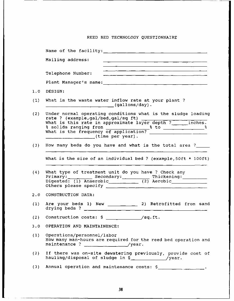
REED BED TECHNOLOGY QUESTIONNAIRE
Name of the facility:
Mailing address:
Telephone Number:
Plant Manager's name:
1.0 DESIGN:
(1) What is the waste water inflow rate at your plant ?(gallons/day).
(2) Under normal operating conditions what is the sludge loadingrate ? (example,gal/bed,gal/sq ft)What is this rate in approximate layer depth ? inches.% solids ranging from % to %What is the frequency of application?
(time per year).
(3) How many beds do you have and what is the total area ?
What is the size of an individual bed ? (example,50ft * 100ft)
(4) What type of treatment unit do you have ? Check anyPrimary: _ Secondary: Thickening:Digested: (1) Anaerobic_(2) AerobicOthers please specify
2.0 CONSTRUCTION DATA:
(1) Are your beds 1) New 2) Retrofitted from sanddrying beds ?
(2) Construction costs: $ /sq.ft.
3.0 OPERATION AND MAINTAINENCE:
(1) Operations/personnel/laborHow many man-hours are required for the reed bed operation andmaintenance ? /year.
(2) If there was on-site dewatering previously, provide cost ofhauling/disposal of sludge in $ /year.
(3) Annual operation and maintenance costs: $
38
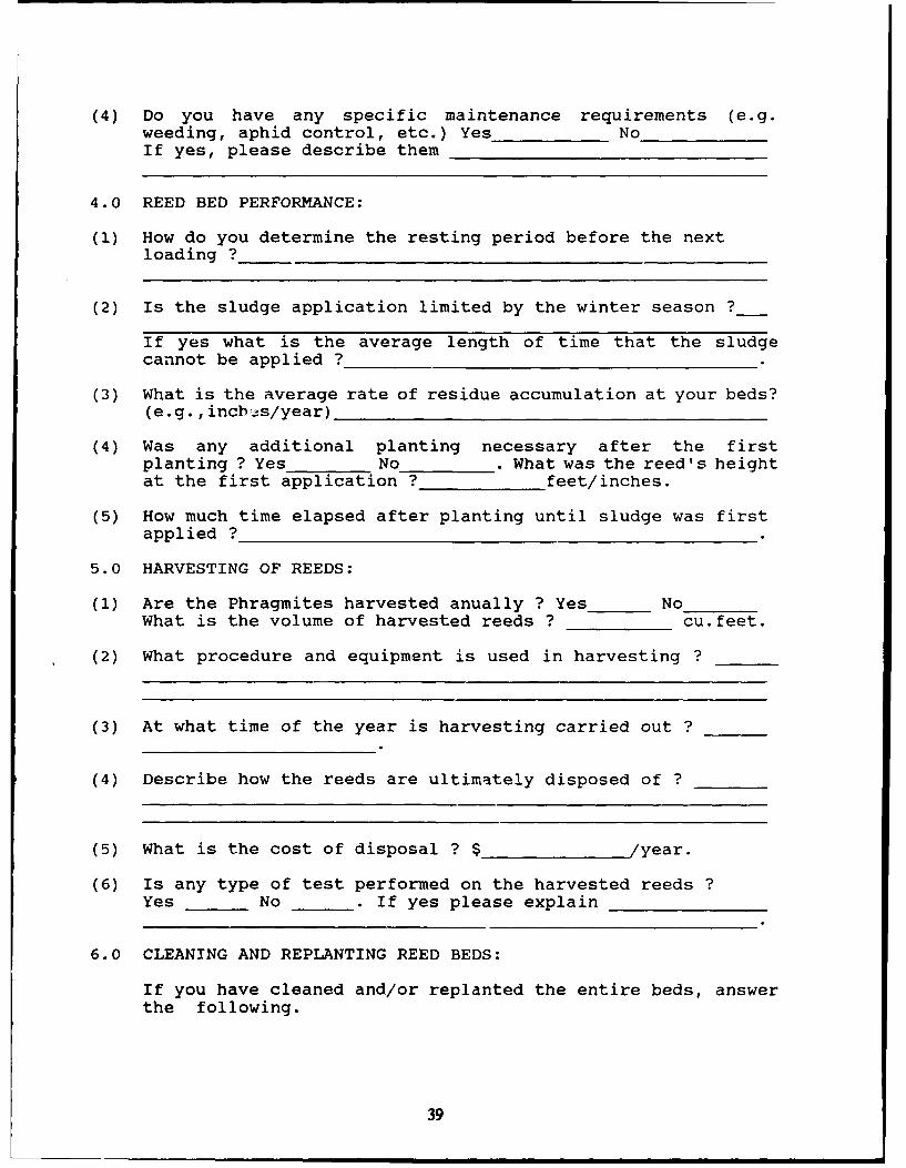
(4) Do you have any specific maintenance requirements (e.g.weeding, aphid control, etc.) Yes NoIf yes, please describe them
4.0 REED BED PERFORMANCE:
(1) How do you determine the resting period before the nextloading ?
(2) Is the sludge application limited by the winter season ?
If yes what is the average length of time that the sludgecannot be applied ?
(3) What is the average rate of residue accumulation at your beds?(e.g.,incbhs/year)
(4) Was any additional planting necessary after the firstplanting ? Yes No . What was the reed's heightat the first application ? feet/inches.
(5) How much time elapsed after planting until sludge was first
applied ?
5.0 HARVESTING OF REEDS:
(1) Are the Phragmites harvested anually ? Yes NoWhat is the volume of harvested reeds ? cu.feet.
(2) What procedure and equipment is used in harvesting ?
(3) At what time of the year is harvesting carried out ?
(4) Describe how the reeds are ultimately disposed of ?
(5) What is the cost of disposal ? $ /year.
(6) Is any type of test performed on the harvested reeds ?Yes No . If yes please explain
6.0 CLEANING AND REPLANTING REED BEDS:
If you have cleaned and/or replanted the entire beds, answerthe following.
39
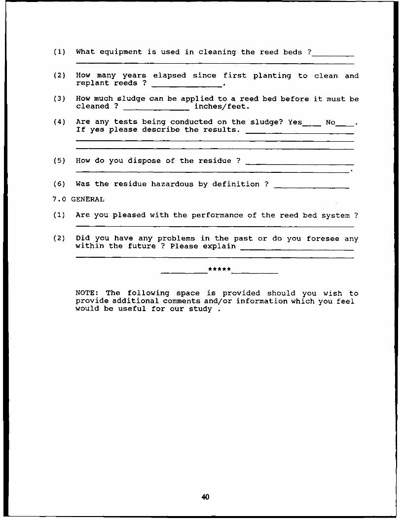
(1) What equipment is used in cleaning the reed beds ?
(2) How many years elapsed since first planting to clean andreplant reeds ?
(3) How much sludge can be applied to a reed bed before it must becleaned ? inches/feet.
(4) Are any tests being conducted on the sludge? Yes_ NoIf yes please describe the results.
(5) How do you dispose of the residue ?
(6) Was the residue hazardous by definition ?
7.0 GENERAL
(1) Are you pleased with the performance of the reed bed system ?
(2) Did you have any problems in the past or do you foresee anywithin the future ? Please explain
NOTE: The following space is provided should you wish toprovide additional comments and/or information which you feelwould be useful for our study
40
USACERL DISTRIBUTION
Chef of Boomamo HQ XVIII Aemheins Carps 213 Pust Leaneutd Wood 65073ATTN. CEHBC-IM-LH (2) ATTN APZA-EKH-BB ATTN: ATSE-DAC4.9 (3)ATTN: CENDC-IM-LP (2) ATTN ATZA-TB-SWATTN: CBCO 4dm Ideary Djv (2aC1) ATTN: ATSEC7LOATTN CERD-M AM:N AFZC-FE 10913 ATTN: ATSB40kAC-PLATTN: CECC-PATTN: CEMDL PCt Pick"a 231111 Military ID* of WASHATrN: CECW-P ATTN: APZA-WP-f Pan W~NW~ATTN: CECW-PR ATT'N. AMEN 20319ATTN- CEMPW-f US Amuy blab" Comamnad (AMC)ATTN: CEWtC Abhaeaukie VA 223334)001 USA Beg Activity, Capil AmaATTN: CECW-O AM:N ANK3N-p ATTN: Lbwy 22211ATTN: CECW immtallos...ATTN: CERN ATTN: DEH (19) Notice APE 92409ATTN: CEMP ATTN: UkmyATT7N CERD-C POESCOMATTN CEMP-M Parl Gile.., & )edPhmmu 30330 US Aimy ARDBC 0790ATTN: CEMPA ATTN: PCEN ATTN. ShICAR.1ERATTN: CERD-ZA IueallealmonATTN: DABN-ZCM ATTN: DBN (23) Charles B Kelly Spt Acov"tATTN- DAEN ZCR ATWN: DEN 15071ATTN: DABN-ZCI 6dm1 IdEAaty DiVNIS (Li#A)
ATTN: APVR-DE 99505 Bog S-nbm IfAb-yCEO'W ATTN: APVKt-WP-D 9973 ATTN: Acaqmiono I0017
AM:N CECPW-F 22060ATTN: CECPW-TT 22060 fissiona Gurd Become 20310 Deomen. Nwmm AgencyATTN: CECPW-ZC 22D60 ATTN: hegtallabam Div ATTN: NADS 20305ATTN: DErr III 7990
Fort EBhe 2206 Dm6.... Lag- AgeuryUS Aimy Bag Diic ATTN. CBTEC.IM-T AWTN. DLA-WI 22304ATTN: Ubhamy (40) ATTN: CBCC-R 2206D
ATTN: Bogr Saamelp Sbdme Car Weber Rood Aimy Mocissel Car 2030Y7US Aimy Bagr Dwisimar AMT: Anomalous Wwoma OfficeATTN: Library (13) US M~arby Acadomy, 10996
USA Nahak RD&B Cemer 01760 ATTN: MABIAUS Aimy Buroe. ATTN: S'TRNC-DT ATTN: Pacilfem BapumATTN. ABABN-flH 09014 ATTN: DRDNA-F ATTN: Geography & flow flugATTN: ABABN ODCS 09014V cap. 7RADOC 416dm Ballmmor Couunow 60623
ATTN DEH (8) Pon Macro. 23651 ATTN: Giham, USANR CarvII Camp" ATTN: ATBlO-
AM!N DEN (11) Ilesaall~ainsi USA Japan. (USAIJ)291h Ama Smparm Growa ATTN DEN (20) ATTN: APA1-fl-BS 96343
ATTN: ABRAS-FA 09054 ATTN: HONSHU 9634100th S.appa miop, US Aimy Mabuiale Tech Lab ATTN: DE1I-(losaws 96576
ATTN. AETT-EN-DEN 09114 ATTN. SLCUT-DEH 02172222d os Beam Eeali Noval Paalhma Bag Caaemaad
ATTN: ABTV-EHR-B 09034 USARPAC 96195 ATTN. Pe~timaflag Cammand (2)235th Bee" Support Bertelse ATTN. DEN ATTN: Dkaoa.Offiam (11)
ATTN. Uum 23614 Aaab~ab 09177 ATTN: APBN-A ATTN: P.M. waskCmmow (S)293d Bas Sappart Baaiamo AWTN: Naval Cancer Baneama Ca 93043
ATTN: AflUSG-MA-ASr-WO-B 090116 SHAPE 09705 AM:N Naval COvW fla Serice Cabra (3) 93043409dm Sqaoa Badealmam(3mc) ATTN. Imhmawtu. Breanc LANDIA
ATTN: AETTO-DEN 09114 1dm US Assay Kaoea412th Beam Support Betausumn 09630 Ans, Boommet. ADC-Amu Offica ATTN. DEN (12)
ATTN: Unit 31401 Arnold Air Faces Shea.. Thl 37389Prehfort Boeom su~p" Beak..n US Aimy NBC
ATTN. Unit 2572 09242 HQ USBUCOM 09i2 Pust Sees Hamamen 73234CMTC Nabmmela 0173 ATTN: ECJ4-LIB ATTN: HSLO-P
ATTN. ABTTH-DBN Iecmnefams Amiy Mosbcal CisMae.. Gmrmany 09135 AMMRC 02172 AM:N HSHG-WBI WN04
ATTN. RSB-MZ41 ATTN. DBXMR-AP21[at Sqappit CamWAe ATTN: DRXMR-WE Tynmdall APE 32403
ATTN. DEN (10) AMTN APE9C Prep.am 0*iUS Aemy Berko CEWES 39180 ATTN: Bang& Srvc Labe
ATTN. ABEA-EN 0935 ATTN. UlveryATTN. AREA-EN 09235 USA TSARCOM 63120
SETAP CECEL 03755 ATTN STSAS-PATTN. ABSB-RN-D 09613 ATTN. LikeuyATTN: ABSE-EN 09630 Amemiscom Publi Wake Asaet. 6W67
Superior Allied Comtataad USA AMCOMATTN. ACSGEE8 0973 AM:N Pacilitim Begr 21719 US Aemy Emma Hyapm ApiayATTN. SHIHB)BN(Vt 09705 ATTN. AMSMC-IR 61299 ATTN. HSH9-ME 21010
ATTN. FeciiiMms Bagr (3) 9%613INSCOM US Gwv't Pavieed Ofi~m 20401ATTN: tALOG-l 22060 USAARMC 40121 ATTN. Baa SmiDmpmit See, (2)ATTN. IAV-DEN 22116 ATTN. A'rllC-EH
Neel lmitmeme of SU.admmi & TombUSA TACOM 4839 Utmury Tralla Momit Comemard ATTN: .Lihey 208f9ATTN: AItTA-XE ATM:N. MBA-03-ENP 07002
ATTN. MT4.OP 20315 Ddefens Temb bil Com 22304Downm Dmuibvbu, R"gt Boo ATTN. MTU-SU-PE 28461 ATTN. DTIC-PAB (2)
ATTN. DWRB-WI 17070 ATTN. MTW-3B 946263w2
9193
This pabblcaba wu ireprolitced on reycded pape. *U.S. GOVERNMENT PRINTING OFFICL. 1993--35l0-SI80063