an autonomic service delivery platform for service
TRANSCRIPT
ABSTRACT
CALLAWAY, ROBERT DAVID. An Autonomic Service Delivery Platform for Service-OrientedNetwork Environments. (Under the direction of Michael Devetsikiotis and Yannis Viniotis.)
Service-oriented architectures offer a more effective and flexible approach to integrating
technology with business processes than traditional information technology (IT) architectures.
Service-oriented architectures are the foundation for both next-generation telecommunications
and middleware architectures, which are rapidly converging on top of commodity transport ser-
vices. Services such as triple/quadruple play, multimedia messaging, and presence are enabled
by the emerging service-oriented IP Multimedia Subsystem, and allow telecommunications ser-
vice providers to maintain, if not improve, their position in the marketplace. Service-oriented
architectures are aggressively leveraged in next-generation middleware systems as the system
model of choice to interconnect service consumers and providers within and between enterprises.
We leverage previous research in active, overlay, and peer-to-peer networking technolo-
gies, along with recent advances in XML and Web Services, to create the paradigm of service-
oriented networking (SON). SON is an emerging architecture that enables network devices to
operate at the application layer to provide functions such as service-based routing, content
transformation, and protocol integration to consumers and providers. By adding application-
awareness into the network fabric, SON can act as a next-generation federated enterprise service
bus that provides vast gains in overall performance and efficiency, and enables the integration
of heterogeneous environments.
The contributions of this research are threefold: first, we formalize SON as an ar-
chitecture and discuss the challenges in building SON devices. Second, we discuss issues in
interconnecting SON devices to create large-scale service-oriented middleware and telecommu-
nications systems; in particular, we discuss the concept of federations of enterprise service
buses, and present two protocols that enable a distributed service registry to support the feder-
ation. Finally, we propose an autonomic service delivery platform for service-oriented network
environments. The platform enables a self-optimizing infrastructure that balances the goals
of maximizing the business value derived from processing service requests and the optimal
utilization of IT resources.
An Autonomic Service Delivery Platform forService-Oriented Network Environments
by
Robert David Callaway
A dissertation submitted to the Graduate Faculty ofNorth Carolina State University
in partial fulfillment of therequirements for the Degree of
Doctor of Philosophy
Computer Engineering
Raleigh, North Carolina
2008
Approved By:
Dr. Adolfo F. Rodriguez Dr. Mihail L. Sichitiu
Dr. Yannis Viniotis Dr. Andrew J. RindosCo-Chair of Advisory Committee
Dr. Michael DevetsikiotisChair of Advisory Committee

DEDICATION
Dedicated to the memory of my late father,
Michael Brown Callaway,
who taught me the true meaning of courage, determination, perseverance, and love.
ii

BIOGRAPHY
Robert (Bob) David Callaway was born in May of 1982 in Charlotte, North Carolina. He
graduated cum laude from North Carolina State University in May of 2003, with Bachelor of
Science degrees in Computer Engineering and Electrical Engineering and a minor in Business
Management. During his undergraduate education, he participated in the University Scholars
Program and was inducted into the Beta Eta Chapter of Eta Kappa Nu.
Bob has been working under the guidance of Professor Michael Devetsikiotis as a Re-
search Assistant since January of 2002 and joined the graduate program at NC State University
in the summer of 2003. He earned the Master of Science degree in Computer Networking in
December of 2004. He is currently a candidate for the Doctor of Philosophy degree in Computer
Engineering, focused on the area of service-oriented networking. His research and development
interests are in network performance, service engineering, and distributed systems. Bob was
awarded an IBM PhD Fellowship for the 2007-2008 academic year. He has also recieved two
IBM Invention Achievement Awards and has five patent applications pending in the U.S.
Upon completion of his doctoral degree, Bob will join the WebSphere Technology
Institute of IBM Software Group as an Advisory Software Engineer, focusing on the design and
development of next-generation middleware appliances.
iii

ACKNOWLEDGEMENTS
I would like to express my profound appreciation to my advisor, Dr. Mike Devetsikio-
tis, for giving me the opportunity to work with him for the last six years. I am deeply indebted
to him for providing a supportive environment for my undergraduate and graduate research.
His insight, patience, and encouragement have been invaluable to me during this process and
have undoubtedly changed me for the better.
I would also like to give thanks to Dr. Yannis Viniotis for his passionate assistance
with the direction of this research. Our numerous discussions and his insightful suggestions
have greatly increased the quality, as well as the impact, of my PhD.
I would have never started this journey, if not for the advice of Dr. Andy Rindos.
He was just as helpful as our paths crossed again as he moved from the role of my “queueing
theory instructor” to my manager at IBM. His support of me and this work was crucial for its
completion, and for that I am sincerely appreciative. Also many thanks to Dr. Tom Bradicich
and Dr. Norm Strole for their advice that led me down this rewarding academic path.
I must also give special thanks to Dr. Adolfo Rodriguez for being a very patient
mentor and, more importantly, a good friend and colleague. His insight, vision, and guidance
were critical to the success of this work, and his support and confidence in me throughout the
last three years have made this a fulfilling and enjoyable endeavour.
Also, special thanks are due to Dr. Mihail Sichitiu and Dr. Sharon Setzer for serving
on my advisory committee, to Kyle Brown and Dr. Rick Robinson for their assistance with the
ESB federation work, and to Dr. Bart Vashaw for providing me with the opportunity to join
the WebSphere Technology Institute, as well as for the financial support that has sustained me
throughout the last three years.
On a more personal note, I would also like to express my love and gratitude to my
wife, Gina, for being there for me throughout the last nine years. Your patience, love, and
compassion are truly inspring to me, and I cannot even begin to thank you for all that you do
for me. I love you more than words can say, and I can’t wait for the rest of our lives together.
Very special thanks are also due to my family (Chris, Leslie, Logan, Dale, Maria, Steve,
Lois, Elaine, Ron, and Pam), my close friends (Josh, Kati, David, Liz, Amy, Erik, Praveen, and
Chris), my beloved basset hound, Bella, and my esteemed colleagues at IBM (John, Marcel,
and Murali) for their encouragement and support. Thank you all for the good times, laughter,
smiles, and friendship. You have helped make the time outside of the PhD memorable and
enjoyable, and have reinforced in me that family and friends are truly things to be treasured.
iv

I would like to thank my brother, Tom, for always being there for his little brother.
Your courage is an inspiration to me, and I certainly owe you at least partially for my interest
in technology. I am proud to have you as a brother and grateful for your presence in my life.
Last, but surely not least, I am forever indebted to my parents for everything they
have given me. Mom, thank you for all that you have done in every part of my life. Dad, I owe
so much to you and I strive every day to make you proud of me. Thank you for having been a
wonderful father and role model for me.
v
TABLE OF CONTENTS
List of Figures . . . . . . . . . . . . . . . . . . . . . . . . . . . . . . . . . . . . . . . . . . . . . . . . . . . . . . . . . . . . . . . viii
List of Tables . . . . . . . . . . . . . . . . . . . . . . . . . . . . . . . . . . . . . . . . . . . . . . . . . . . . . . . . . . . . . . . . x
1 Introduction & Motivation . . . . . . . . . . . . . . . . . . . . . . . . . . . . . . . . . . . . . . . . . . . . . . . . 11.1 The Need for Adaptive Service-Oriented Systems in the 21st Century . . . . . . 1
1.1.1 A Brief History of Information Technology . . . . . . . . . . . . . . . . . 21.2 Service-Oriented Architectures . . . . . . . . . . . . . . . . . . . . . . . . . . . . 4
1.2.1 Enterprise Service Bus . . . . . . . . . . . . . . . . . . . . . . . . . . . . . 41.2.2 The Emergence of XML . . . . . . . . . . . . . . . . . . . . . . . . . . . . 51.2.3 Web Services . . . . . . . . . . . . . . . . . . . . . . . . . . . . . . . . . . 5
1.3 Contributions of this Dissertation . . . . . . . . . . . . . . . . . . . . . . . . . . . 61.4 Outline of this Dissertation . . . . . . . . . . . . . . . . . . . . . . . . . . . . . . 8
2 Service-Oriented Networking . . . . . . . . . . . . . . . . . . . . . . . . . . . . . . . . . . . . . . . . . . . . . . 102.1 Previous Efforts in Application-Aware Networking . . . . . . . . . . . . . . . . . 10
2.1.1 Active Networks . . . . . . . . . . . . . . . . . . . . . . . . . . . . . . . . 102.1.2 Overlay Networks . . . . . . . . . . . . . . . . . . . . . . . . . . . . . . . 11
2.2 The Paradigm of Service-Oriented Networking . . . . . . . . . . . . . . . . . . . . 112.2.1 Benefits . . . . . . . . . . . . . . . . . . . . . . . . . . . . . . . . . . . . . 122.2.2 Functions . . . . . . . . . . . . . . . . . . . . . . . . . . . . . . . . . . . . 13
2.3 Research Challenges in Building SON Devices . . . . . . . . . . . . . . . . . . . . 162.3.1 Implementation Considerations . . . . . . . . . . . . . . . . . . . . . . . . 162.3.2 Robustness . . . . . . . . . . . . . . . . . . . . . . . . . . . . . . . . . . . 172.3.3 Specialized Hardware . . . . . . . . . . . . . . . . . . . . . . . . . . . . . 182.3.4 Security . . . . . . . . . . . . . . . . . . . . . . . . . . . . . . . . . . . . . 182.3.5 Resource Allocation . . . . . . . . . . . . . . . . . . . . . . . . . . . . . . 18
2.4 Research Challenges in Interconnecting SON Devices . . . . . . . . . . . . . . . . 192.4.1 Manageability . . . . . . . . . . . . . . . . . . . . . . . . . . . . . . . . . . 192.4.2 Resource Allocation . . . . . . . . . . . . . . . . . . . . . . . . . . . . . . 20
2.5 Conclusions . . . . . . . . . . . . . . . . . . . . . . . . . . . . . . . . . . . . . . . 21
3 Large-Scale Service-Oriented Systems . . . . . . . . . . . . . . . . . . . . . . . . . . . . . . . . . . . . . 223.1 Introduction & Motivation . . . . . . . . . . . . . . . . . . . . . . . . . . . . . . . 223.2 Current Approaches to ESB Federation . . . . . . . . . . . . . . . . . . . . . . . 24
3.2.1 Manual Configuration . . . . . . . . . . . . . . . . . . . . . . . . . . . . . 243.2.2 Broker ESB . . . . . . . . . . . . . . . . . . . . . . . . . . . . . . . . . . . 243.2.3 Centralized Registry . . . . . . . . . . . . . . . . . . . . . . . . . . . . . . 25
3.3 Federation Architecture . . . . . . . . . . . . . . . . . . . . . . . . . . . . . . . . 253.3.1 Related Work . . . . . . . . . . . . . . . . . . . . . . . . . . . . . . . . . . 28
3.4 Building an Autonomous Federation . . . . . . . . . . . . . . . . . . . . . . . . . 29
vi
3.4.1 Service Request Forwarding . . . . . . . . . . . . . . . . . . . . . . . . . . 323.5 Interconnecting Autonomous Federations . . . . . . . . . . . . . . . . . . . . . . 35
3.5.1 Service Request Forwarding . . . . . . . . . . . . . . . . . . . . . . . . . . 393.6 Conclusions . . . . . . . . . . . . . . . . . . . . . . . . . . . . . . . . . . . . . . . 41
4 An Autonomic Service Delivery Platform . . . . . . . . . . . . . . . . . . . . . . . . . . . . . . . . . 424.1 Introduction . . . . . . . . . . . . . . . . . . . . . . . . . . . . . . . . . . . . . . . 424.2 Architecture of Service Delivery Platform . . . . . . . . . . . . . . . . . . . . . . 44
4.2.1 Overview . . . . . . . . . . . . . . . . . . . . . . . . . . . . . . . . . . . . 444.2.2 Key Assumptions . . . . . . . . . . . . . . . . . . . . . . . . . . . . . . . . 444.2.3 Methodologies Integrated in the Platform . . . . . . . . . . . . . . . . . . 464.2.4 Related Work in Service Systems . . . . . . . . . . . . . . . . . . . . . . . 49
4.3 Analytic Framework of Service Delivery Platform . . . . . . . . . . . . . . . . . . 504.3.1 Distributed Algorithm . . . . . . . . . . . . . . . . . . . . . . . . . . . . . 52
4.4 Engineering Tradeoffs in the Service Delivery Platform . . . . . . . . . . . . . . . 544.4.1 Fairness versus Efficiency . . . . . . . . . . . . . . . . . . . . . . . . . . . 544.4.2 Concavity versus Nonconcavity . . . . . . . . . . . . . . . . . . . . . . . . 55
4.5 Simulation . . . . . . . . . . . . . . . . . . . . . . . . . . . . . . . . . . . . . . . . 584.5.1 Experimental Setup . . . . . . . . . . . . . . . . . . . . . . . . . . . . . . 584.5.2 No Congestion Functions . . . . . . . . . . . . . . . . . . . . . . . . . . . 604.5.3 Delay Sensitive Function . . . . . . . . . . . . . . . . . . . . . . . . . . . . 704.5.4 Hop Count Congestion Function . . . . . . . . . . . . . . . . . . . . . . . 75
4.6 Conclusions . . . . . . . . . . . . . . . . . . . . . . . . . . . . . . . . . . . . . . . 79
5 Conclusions . . . . . . . . . . . . . . . . . . . . . . . . . . . . . . . . . . . . . . . . . . . . . . . . . . . . . . . . . . . . . . . 815.1 Summary of this Dissertation . . . . . . . . . . . . . . . . . . . . . . . . . . . . . 815.2 Future Work . . . . . . . . . . . . . . . . . . . . . . . . . . . . . . . . . . . . . . 82
5.2.1 Multipath XML-Based Service Routing Protocols . . . . . . . . . . . . . . 825.2.2 Minimizing Optimization Computations using Wavelet-Based Traffic
Prediction . . . . . . . . . . . . . . . . . . . . . . . . . . . . . . . . . . . . 825.2.3 Measurement of Effective Capacity of Resources . . . . . . . . . . . . . . 83
Bibliography . . . . . . . . . . . . . . . . . . . . . . . . . . . . . . . . . . . . . . . . . . . . . . . . . . . . . . . . . . . . . . . . . 85
Appendices . . . . . . . . . . . . . . . . . . . . . . . . . . . . . . . . . . . . . . . . . . . . . . . . . . . . . . . . . . . . . . . . . . 94
Appendix A Intra-Federation Routing Protocol Specification . . . . . . . . . . . . . . . . 95
vii
LIST OF FIGURES
Figure 1.1 Evolution of Information Technology Architectures . . . . . . . . . . . . . . . . . . . . . . . . . . 2Figure 1.2 Diagram of an Enterprise Service Bus . . . . . . . . . . . . . . . . . . . . . . . . . . . . . . . . . . . . . . . 5Figure 1.3 Estimated Percentage of XML in Overall Network Traffic . . . . . . . . . . . . . . . . . . . . 6
Figure 2.1 Example of Functional Offloading . . . . . . . . . . . . . . . . . . . . . . . . . . . . . . . . . . . . . . . . . . . 14Figure 2.2 Example of Service Integration . . . . . . . . . . . . . . . . . . . . . . . . . . . . . . . . . . . . . . . . . . . . . . 14Figure 2.3 Example of Intelligent Routing . . . . . . . . . . . . . . . . . . . . . . . . . . . . . . . . . . . . . . . . . . . . . . 16Figure 2.4 Comparison of Software and Appliance Approaches . . . . . . . . . . . . . . . . . . . . . . . . . . 17Figure 2.5 Example of Adaptive Admission Control: SEDA Response Time Controller . . 19
Figure 3.1 Example Topology of Multiple ESB Deployments - Hub & Spokes . . . . . . . . . . . 26Figure 3.2 Example Topology of Multiple ESB Deployments - Peer Business Divisions . . 26Figure 3.3 Example Topology of Interconnected Autonomous Federations . . . . . . . . . . . . . . . 27Figure 3.4 Message Exchange Between Two ESBs Within a Federation . . . . . . . . . . . . . . . . . 31Figure 3.5 Example of Contents of Hello XML Message . . . . . . . . . . . . . . . . . . . . . . . . . . . . . . . . . 31Figure 3.6 Example of Contents of Database Description XML Message . . . . . . . . . . . . . . . . 32Figure 3.7 Example of Contents of Acknowledgement Database Description XML Message 33Figure 3.8 Example of Contents of Service State Update XML Message . . . . . . . . . . . . . . . . . 34Figure 3.9 Flowchart for Forwarding Service Requests within a Federation of Enterprise
Service Buses. . . . . . . . . . . . . . . . . . . . . . . . . . . . . . . . . . . . . . . . . . . . . . . . . . . . . . . . . . . . . . . . . . . . . . . 34Figure 3.10 Message Exchange Between Two Autonomous Federations . . . . . . . . . . . . . . . . . . . 36Figure 3.11 Example of Contents of Open XML Message . . . . . . . . . . . . . . . . . . . . . . . . . . . . . . . . 36Figure 3.12 Example of Contents of KeepAlive XML Message. . . . . . . . . . . . . . . . . . . . . . . . . . . . 37Figure 3.13 Example of Contents of Update XML Message . . . . . . . . . . . . . . . . . . . . . . . . . . . . . . 37Figure 3.14 Example of Contents of Notification XML Message . . . . . . . . . . . . . . . . . . . . . . . . . . 38Figure 3.15 Message Exchange Between Three Autonomous Federations . . . . . . . . . . . . . . . . . 38Figure 3.16 Example of Contents of Open XML Message . . . . . . . . . . . . . . . . . . . . . . . . . . . . . . . . 38Figure 3.17 Example of Contents of KeepAlive XML Message. . . . . . . . . . . . . . . . . . . . . . . . . . . . 38Figure 3.18 Example of Contents of Update XML Message . . . . . . . . . . . . . . . . . . . . . . . . . . . . . . 39Figure 3.19 Example of Contents of Update XML Message . . . . . . . . . . . . . . . . . . . . . . . . . . . . . . 40Figure 3.20 Flowchart for Forwarding Service Requests Between Autonomous Federations
of Enterprise Service Buses . . . . . . . . . . . . . . . . . . . . . . . . . . . . . . . . . . . . . . . . . . . . . . . . . . . . . . . . . 40
Figure 4.1 Example of SON Topology with Multiple Service Providers . . . . . . . . . . . . . . . . . . 45Figure 4.2 Examples of Nonconcave Utility Functions. . . . . . . . . . . . . . . . . . . . . . . . . . . . . . . . . . . 56Figure 4.3 Service-Oriented Network Topology Used in Simulation . . . . . . . . . . . . . . . . . . . . . . 58Figure 4.4 Topology Matrix for Simulation . . . . . . . . . . . . . . . . . . . . . . . . . . . . . . . . . . . . . . . . . . . . . 59Figure 4.5 Equal Service Priorities: Offered Rates vs. Time . . . . . . . . . . . . . . . . . . . . . . . . . . . . 60Figure 4.6 Equal Service Priorities: Utility vs. Time. . . . . . . . . . . . . . . . . . . . . . . . . . . . . . . . . . . . 61Figure 4.7 Equal Service Priorities: Service 1 Throughput vs. Path and Time . . . . . . . . . . 64Figure 4.8 Equal Service Priorities: Service 2 Throughput vs. Path and Time . . . . . . . . . . 64
viii
Figure 4.9 Weighted Service Priorities: Offered Rates vs. Time . . . . . . . . . . . . . . . . . . . . . . . . . 65Figure 4.10 Weighted Service Priorities: Utility vs. Time . . . . . . . . . . . . . . . . . . . . . . . . . . . . . . . . 66Figure 4.11 Weighted Service Priorities: Service 1 Throughput vs. Path and Time . . . . . . . 69Figure 4.12 Weighted Service Priorities: Service 2 Throughput vs. Path and Time . . . . . . . 69Figure 4.13 Delay Sensitive Service: Utility vs. Delay . . . . . . . . . . . . . . . . . . . . . . . . . . . . . . . . . . . . 71Figure 4.14 Delay Sensitive Service: Service 1 Throughput vs. Path and Delay. . . . . . . . . . . 74Figure 4.15 Delay Sensitive Service: Service 2 Throughput vs. Path and Delay. . . . . . . . . . . 74Figure 4.16 Hop Count Sensitive Service: Utility vs. Gamma . . . . . . . . . . . . . . . . . . . . . . . . . . . . 76Figure 4.17 Hop Count Sensitive Service: Service 1 Throughput vs. Path and Gamma . . . 78Figure 4.18 Hop Count Sensitive Service: Service 2 Throughput vs. Path and Gamma . . . 78
Figure 5.1 Using Traffic Prediction Algorithms to Minimze Optimization Calculations . . 83
Figure A.1 Mediation State Machine . . . . . . . . . . . . . . . . . . . . . . . . . . . . . . . . . . . . . . . . . . . . . . . . . . . . 110Figure A.2 Peer State Machine . . . . . . . . . . . . . . . . . . . . . . . . . . . . . . . . . . . . . . . . . . . . . . . . . . . . . . . . . 117
ix
LIST OF TABLES
Table 4.1 Equal Service Priorities: Node Throughput at Time 0 . . . . . . . . . . . . . . . . . . . . . . . . 62Table 4.2 Equal Service Priorities: Node Throughput at Time 100 . . . . . . . . . . . . . . . . . . . . . . 62Table 4.3 Equal Service Priorities: Node Throughput at Time 200 . . . . . . . . . . . . . . . . . . . . . . 63Table 4.4 Equal Service Priorities: Node Throughput at Time 300 . . . . . . . . . . . . . . . . . . . . . . 63Table 4.5 Weighted Service Priorities: Node Throughput at Time 0. . . . . . . . . . . . . . . . . . . . . 66Table 4.6 Weighted Service Priorities: Node Throughput at Time 100 . . . . . . . . . . . . . . . . . . 67Table 4.7 Weighted Service Priorities: Node Throughput at Time 200 . . . . . . . . . . . . . . . . . . 67Table 4.8 Weighted Service Priorities: Node Throughput at Time 300 . . . . . . . . . . . . . . . . . . 68Table 4.9 Delay Sensitive Service: Node D Delay = 1 . . . . . . . . . . . . . . . . . . . . . . . . . . . . . . . . . . . 72Table 4.10 Delay Sensitive Service: Node D Delay = 5 . . . . . . . . . . . . . . . . . . . . . . . . . . . . . . . . . . . 72Table 4.11 Delay Sensitive Service: Node D Delay = 6 . . . . . . . . . . . . . . . . . . . . . . . . . . . . . . . . . . . 72Table 4.12 Delay Sensitive Service: Node D Delay = 7 . . . . . . . . . . . . . . . . . . . . . . . . . . . . . . . . . . . 73Table 4.13 Delay Sensitive Service: Node D Delay = 8 . . . . . . . . . . . . . . . . . . . . . . . . . . . . . . . . . . . 73Table 4.14 Hop Count Sensitive Service: Gamma = 0.005. . . . . . . . . . . . . . . . . . . . . . . . . . . . . . . . 76Table 4.15 Hop Count Sensitive Service: Gamma = 0.01 . . . . . . . . . . . . . . . . . . . . . . . . . . . . . . . . . 77Table 4.16 Hop Count Sensitive Service: Gamma = 0.05 . . . . . . . . . . . . . . . . . . . . . . . . . . . . . . . . . 77
Table A.1 IFRP Message Types. . . . . . . . . . . . . . . . . . . . . . . . . . . . . . . . . . . . . . . . . . . . . . . . . . . . . . . . . 101Table A.2 IFRP Service State Advertisements (SSAs) . . . . . . . . . . . . . . . . . . . . . . . . . . . . . . . . . . . 102Table A.3 Mediation State Transitions . . . . . . . . . . . . . . . . . . . . . . . . . . . . . . . . . . . . . . . . . . . . . . . . . . 113Table A.4 Peer State Transitions . . . . . . . . . . . . . . . . . . . . . . . . . . . . . . . . . . . . . . . . . . . . . . . . . . . . . . . . 120Table A.5 Mediation State Transitions . . . . . . . . . . . . . . . . . . . . . . . . . . . . . . . . . . . . . . . . . . . . . . . . . . 133Table A.6 The SSA’s Service State ID . . . . . . . . . . . . . . . . . . . . . . . . . . . . . . . . . . . . . . . . . . . . . . . . . . 134Table A.7 Sending Service State Acknowledgments . . . . . . . . . . . . . . . . . . . . . . . . . . . . . . . . . . . . . . 148
x
Chapter 1
Introduction & Motivation
1.1 The Need for Adaptive Service-Oriented Systems in the 21st
Century
Over the past 15 years, the global economy has been dramatically altered by the
pervasive nature of information technology (IT) and networking. The resulting interconnected
global marketplace, where information is the transactional medium, has caused a dramatic shift
in the global economy. For example, the service sector of the U.S. economy, the primary user of
IT across all other economic categories, contributes to over eighty percent of the nation’s gross
domestic product [1]. Successful service-based systems can autonomically adapt to changes and
advances in business processes, IT, and the global marketplace [2]. Furthermore, the penetration
of the Internet into global culture further increases the importance for businesses to adapt to
an increasingly quality-sensitive, content-driven customer base. The ability to offer dynamic,
stable, robust, and high performance service offerings is, and will continue to be, crucial to
corporations in the 21st century.
One example of the transformation required in industries due to the influence of IT
can be observed in the case of telecommunications service providers. Telecommunications ser-
vices, such as the basic landline telephone system in the U.S., were relatively profitable for
service providers in the latter end of the 20th century. These traditional telephone providers
primarily depended on value-added services (such as long distance, caller ID, and voicemail)
to generate the majority of their operational profits, since they allowed the providers to differ-
entiate themselves in the marketplace. Today, however, telecommunications services like the
basic voice transport service are becoming commoditized due to competition from voice-over-IP
1
telecommunications providers. Network service providers are earning low profit margins with
high operational investments while being compelled to provide a near-perfect quality-of-service
to satisfy their customers. This is not surprising since basic economic theory states that profit
and degree of commoditization are inversely proportional to one another.
1.1.1 A Brief History of Information Technology
Due to the pervasive nature of IT in corporations, heterogeneity and change are the
greatest issues facing IT managers today [3]. Even with wider adoption of open standards, it
remains a daunting task to make legacy IT systems communicate across vendor, protocol, and
software differences. The rate of change in available hardware and software products enhances
the difficulty of supporting a dynamic infrastructure that is adaptable to business requirements
and industry trends.
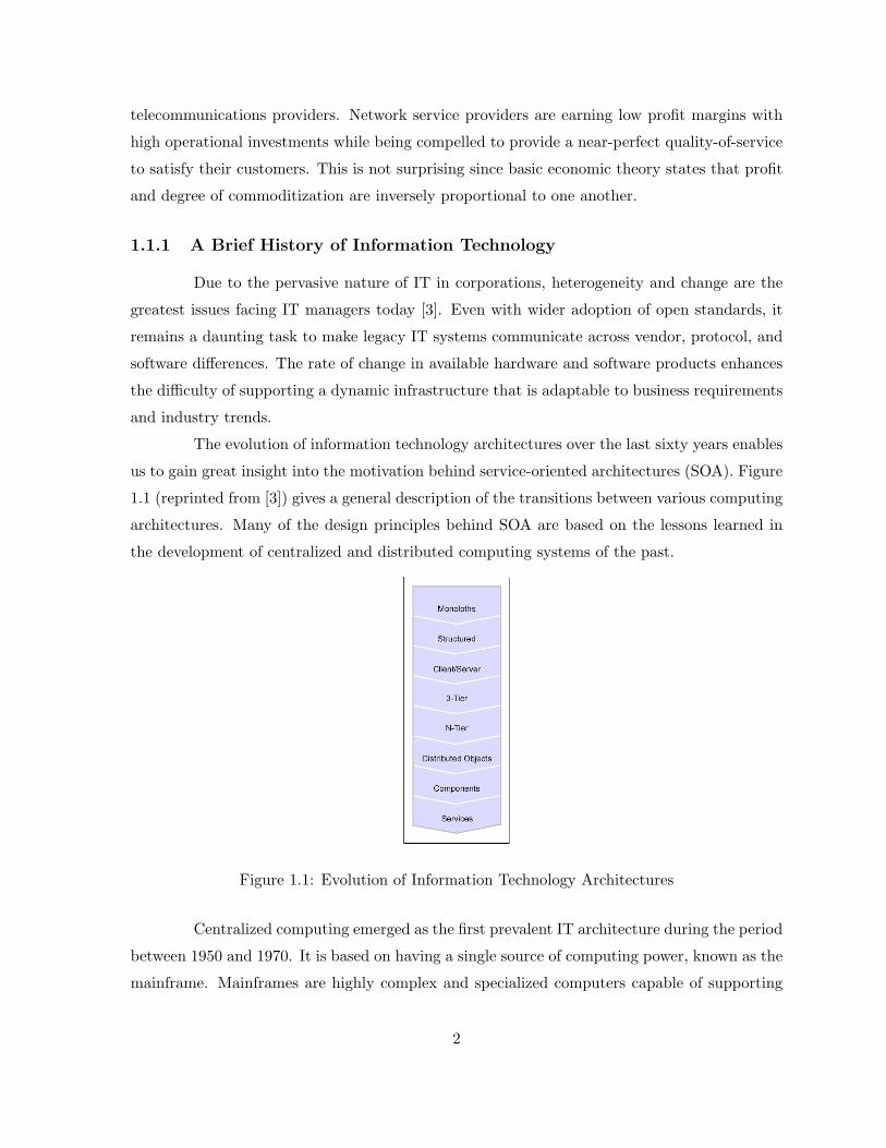
The evolution of information technology architectures over the last sixty years enables
us to gain great insight into the motivation behind service-oriented architectures (SOA). Figure
1.1 (reprinted from [3]) gives a general description of the transitions between various computing
architectures. Many of the design principles behind SOA are based on the lessons learned in
the development of centralized and distributed computing systems of the past.
Figure 1.1: Evolution of Information Technology Architectures
Centralized computing emerged as the first prevalent IT architecture during the period
between 1950 and 1970. It is based on having a single source of computing power, known as the
mainframe. Mainframes are highly complex and specialized computers capable of supporting
2
numerous processors and thousands of users simultaneously. Users interacted with traditional
mainframes using “dumb-clients”, terminals that did not perform local processing of programs
or data that a user was requesting.
With the increase in development of smaller computers, and eventually with the release
of the personal computer (PC) in the early 1980s, the influence of the computer became more
widespread. With this, users possessed the capability to perform some processing on their own
PC, yet leave more complicated tasks to the mainframes or more powerful personal computers
known as servers. These innovations sparked the deployment of the first architecture based on
distributed computing principles that became known as the Client/Server model. Computer
and telecommunication networks played a larger role as systems became interconnected in order
to support this architecture.
The wide-scale adoption of the Internet and graphical user interface continued to
push the development of distributed systems even further. Basic applications, such as e-mail
clients and web browsers, became extremely popular; this led to the development of more
advanced Internet-enabled applications, such as instant messaging and e-commerce. Web sites
that featured dynamic content helped to drive the development of three-tier and multi-tier
architectures. In a three-tier architecture, the first tier would typically contain web servers
responsible for acting as user agents. These servers would format and send data received from
the second tier, which is comprised of application servers. Application servers, which execute
the requisite business logic based upon data retrieved from databases, comprise the third layer.
As computers continued to infiltrate into almost every industry, application servers
and middleware systems became more prevalent in corporations. However, many corporations
had disparate systems running a variety of applications that neededto cooperate with one
another. This need inspired the development and deployment of distributed objects, based
upon standards for software modules that are designed to work together but reside in multiple
systems throughout an organization; examples of these standards are the Common Object
Request Broker Architecture (CORBA) [4], Distributed Component Object Model [5], and
Java Remote Method Invocation [6].
The ability to componentize these distributed objects and their reuse throughout an
enterprise can have impact in terms of shorter application development time and fewer soft-
ware bugs. The three primary componentization efforts are CORBA Componentization Model,
Enterprise Java Beans (EJBs), and Component Object Model. The popularity of component-
based software development has been assisted by the prevalence of object-oriented programming
3
languages and techniques.
Middleware consists of software agents acting as an intermediary between different
application components. Software packages, such as IBM WebSphere [7], support the devel-
opment and deployment of software components, such as EJBs. Middleware can be viewed as
the glue that enables the integration of disparate applications with other software components
within an enterprise.
1.2 Service-Oriented Architectures
Service-oriented architectures were designed to be the next generation of middleware
systems that directly addressed the issues of heterogeneity and change that existed in previous
IT architectures [8]. They integrate the concepts of enterprise service buses and web services,
which are discussed in Sections 1.2.1 and 1.2.3, respectively.
Services, the core unit of an SOA, are defined as “a course-grained, discoverable soft-
ware entity that exists as a single instance and interacts with applications and other services
through a loosely coupled, message-based communication model” [3]. Services are based on
the idea that IT infrastructures should be directly aligned with relevant business processes,
rather than with the more traditional horizontal or vertical alignment. Services are comprised
of a combination of various software components that, together, execute a reusable business
function.
One key property of services is that they are loosely coupled with one another within
the SOA. Loosely coupled is defined in [9] as having “no tight transactional properties among
the components.” This property is essential to SOA because it removes dependences on imple-
mentation specifics by relying on interaction between services through standardized interfaces.
Services can be implemented in different languages and deployed on different platforms. The
use of standardized interfaces is the key to the enablement of SOA as a flexible architecture.
If adopted and implemented correctly, SOA can provide a framework that leverages
elements of an existing IT infrastructure, which will reduce costs and provide a more flexible
and robust environment for the integration of IT and business processes.
1.2.1 Enterprise Service Bus
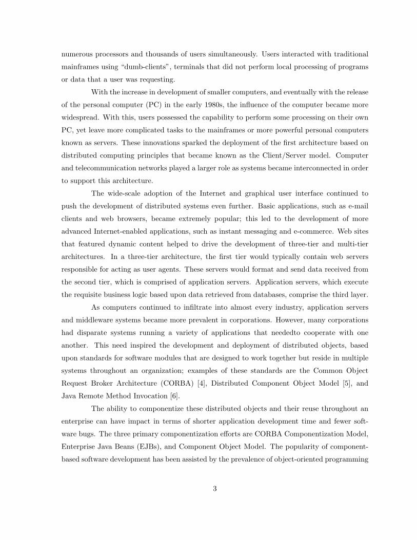
The key item for integration of services within an SOA is the Enterprise Service Bus
(ESB). The goal of an ESB is “to provide virtualization of the enterprise resources, allowing the
4
business logic of the enterprise to be developed and managed independently of the infrastructure,
network, and provision of those business services” [3]. Figure 1.2 (reprinted from [3]) shows the
interaction of the ESB with service providers and consumers. An ESB serves as the centralized
control and administration entity within the architecture, while also being responsible for the
integration and interaction of deployed services [10].
Figure 1.2: Diagram of an Enterprise Service Bus
1.2.2 The Emergence of XML
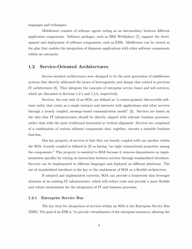
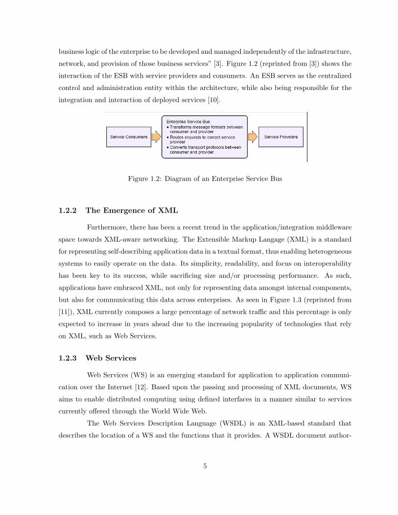
Furthermore, there has been a recent trend in the application/integration middleware
space towards XML-aware networking. The Extensible Markup Langage (XML) is a standard
for representing self-describing application data in a textual format, thus enabling heterogeneous
systems to easily operate on the data. Its simplicity, readability, and focus on interoperability
has been key to its success, while sacrificing size and/or processing performance. As such,
applications have embraced XML, not only for representing data amongst internal components,
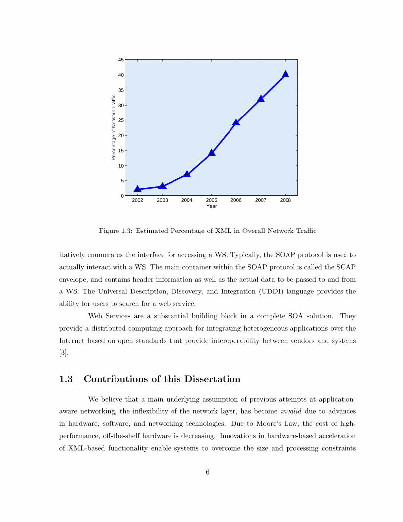
but also for communicating this data across enterprises. As seen in Figure 1.3 (reprinted from
[11]), XML currently composes a large percentage of network traffic and this percentage is only
expected to increase in years ahead due to the increasing popularity of technologies that rely
on XML, such as Web Services.
1.2.3 Web Services
Web Services (WS) is an emerging standard for application to application communi-
cation over the Internet [12]. Based upon the passing and processing of XML documents, WS
aims to enable distributed computing using defined interfaces in a manner similar to services
currently offered through the World Wide Web.
The Web Services Description Language (WSDL) is an XML-based standard that
describes the location of a WS and the functions that it provides. A WSDL document author-
5
2002 2003 2004 2005 2006 2007 20080
5
10
15
20
25
30
35
40
45
Year
Per
cent
age
of N
etw
ork
Tra
ffic
Figure 1.3: Estimated Percentage of XML in Overall Network Traffic
itatively enumerates the interface for accessing a WS. Typically, the SOAP protocol is used to
actually interact with a WS. The main container within the SOAP protocol is called the SOAP
envelope, and contains header information as well as the actual data to be passed to and from
a WS. The Universal Description, Discovery, and Integration (UDDI) language provides the
ability for users to search for a web service.
Web Services are a substantial building block in a complete SOA solution. They
provide a distributed computing approach for integrating heterogeneous applications over the
Internet based on open standards that provide interoperability between vendors and systems
[3].
1.3 Contributions of this Dissertation
We believe that a main underlying assumption of previous attempts at application-
aware networking, the inflexibility of the network layer, has become invalid due to advances
in hardware, software, and networking technologies. Due to Moore’s Law, the cost of high-
performance, off-the-shelf hardware is decreasing. Innovations in hardware-based acceleration
of XML-based functionality enable systems to overcome the size and processing constraints
6
introduced by XML. Linux, a free open-source operating system, has emerged as a cornerstone
in numerous enterprise computing environments due to its robust networking capabilities and
scalability as a platform for hosting mission-critical applications. The prevalence of optical
networking has removed the notion that bandwidth is a restricted commodity within enter-
prise networks. Furthermore, next-generation telecommunications and middleware systems are
converging under the theme of service-orientation. With this convergence, the properties of
network devices and the larger service-oriented network architecture are an emerging and open
research area that draws from a diverse background of prior work in numerous disciplines.
We argue that these factors combine to invalidate the assumption made in previous
attempts - that implementing application-awareness in the network fabric is too costly and
complex; this serves as the motivation for the paradigm of service-oriented networking. This
architecture assumes that XML is now the lingua franca of network communication, and lever-
ages XML-aware devices placed in the network fabric to perform content-based routing, among
many other functions. It is the goal of our research to summarize the breadth of the research
area and make substantial in-depth contributions to particular problems that are currently open
in the literature.
The contributions of our research are as follows:
• We formally name and propose the concept of service-oriented networking (SON). SON
enables network components to become application-aware so that they are able to under-
stand data encoded in XML and act upon that data intelligently to make routing decisions,
enforce QoS or security policies, or transform the data into an alternate representation.
We describe the motivation behind service-oriented networking, the potential benefits
of introducing application-aware network devices into service-oriented architectures, and
discusses research challenges in the development of SON-enabled network appliances as
well as interconnecting them into large-scale service-oriented networks.
• It is often desirable to have multiple ESB deployments federate with one another to
provide a distributed integration platform that promotes the reuse of services within and
across enterprises. However, the existing solutions to federate ESBs are limited by their
inflexibility to change and inability to scale. We propose the enablement of a federation of
enterprise service buses via a distributed service registry and SON that distributes policy-
appropriate service metadata to federation members. We provide a high-level description
of two new protocols that maintain the state of the distributed registry within and between
7
autonomous federations. We argue that the use of a distributed service registry and the
associated enabling protocols is a novel application of existing technology that creates a
robust, scalable, and flexible federation of ESBs that is essential to the next generation
of large-scale SOA deployments.
• Finally, we present a novel autonomic service delivery platform for service-oriented net-
work environments. The platform enables a self-optimizing infrastructure that balances
the goals of maximizing the business value derived from processing service requests and
the optimal utilization of IT resources. We believe that our proposal is the first of its kind
to integrate several well-established theoretical and practical techniques from networking,
microeconomics, and service-oriented computing to form a fully-distributed service de-
livery platform. The principal component of the platform is a utility-based cooperative
service routing protocol that disseminates congestion-based prices amongst intermediaries
to enable the dynamic routing of service requests from consumers to providers. We pro-
vide the motivation for such a platform and formally present our proposed architecture.
We discuss the underlying analytical framework for the service routing protocol, as well
as key methodologies that, together, provide a robust framework for our service delivery
platform that is applicable to the next-generation of middleware and telecommunications
architectures. We discuss issues regarding the fairness of service rate allocations, as well
as the use of nonconcave utility functions in the service routing protocol.
1.4 Outline of this Dissertation
The outline of the dissertation is as follows:
• In Chapter 2, we formally propose Service-Oriented Networking as an emerging architec-
ture. We discuss the challenges, both in building SON devices, as well as in interconnecting
the devices to form a service-oriented network.
• In Chapter 3, we continue the discussion regarding large-scale service-oriented networks.
We explicitly discuss a use case for SON, federations of enterprise service buses. We
describe how federations are enabled by a distributed service registry, and provide details
and examples of two protocols, based on Internet routing protocols, that enable a robust,
scalable and dynamic infrastructure.
8

• In Chapter 4, we present our autonomic service delivery platform. The goal of this
platform is to optimally route requests from service consumers to providers. We provide
details of the underlying utility-based analytic framework, as well as results from an initial
experiment that shows the ability of the framework to optimally route and throttle load
under resource constraints.
• In Chapter 5, we summarize our work and propose extensions for future work on the
autonomic service delivery platform.
• In Appendix A, we provide the specification for the Intra-Federation Routing Protocol,
an instantiation of the concepts presented in Chapter 3.
9
Chapter 2
Service-Oriented Networking
2.1 Previous Efforts in Application-Aware Networking
Application-aware networks, which provide differential treatment of traffic dependent
on application data, are an emerging technology that promises to provide increased end-to-
end system performance for next-generation applications and networks. Internet Protocol (IP)
routers currently attempt to be application-aware and regularly inspect application data con-
tained in packets; for example, a router may compare passing application data to a virus
signature and discard the traffic when a positive match is triggered. In the past, the bulk
of application data that traversed the network was built around a wide array of closed and
proprietary data specifications. As a result, the majority of network components have re-
mained application-agnostic. However, there have been two significant research areas that have
addressed issues in this area. Active and overlay networks have both attempted to provide
application-aware functionality in the network without an open standard for application-to-
application communication.
2.1.1 Active Networks
Active networks sought to improve the deployment of emerging networking technolo-
gies and protocols by adding application layer functionality in specific active nodes. While data
would still be passed in packets as in a traditional packet-switched network, active networks
would support “smart” packets, which would carry bytecode, along with data, to be executed
in active nodes. The main underlying assumption in active network research is that the net-
work layer is inflexible and cannot adapt to the dynamic requirements of emerging network
10
services. Since standardization of new protocols is often a lengthy process, active network
technology attempted to leverage advances in compilers, operating systems, and programming
languages that would facilitate running user-supplied code in active nodes [13, 14]. Several
groups [15, 16, 17] proposed examples of potential architectures for the organization of infor-
mation and program code into the packet headers, showing results in which active networks
suffer a slight degradation in performance when compared with a software router.
However, active networks were not widely deployed due to issues with security, resource
allocation, and the substantial cost of deployment. Since packets could contain arbitrary code
to be executed on an active node, precautions must be taken to ensure that a rogue user
could not execute code that would corrupt the operations of other users. It is essential to
manage the computing resources of the node to ensure that programs are fair to each other.
Furthermore, the deployment of active network technology in the network would require a
substantial investment for network operators in order to support this new architecture.
2.1.2 Overlay Networks
The development and subsequent deployment of active networks showed that enabling
application-awareness in the network by executing user-supplied code in the network layer is
infeasible. Overlay networks sought to provide application-aware functionality by pushing the
complexity of such algorithms towards the end users of the network. The major assumption
in overlay networks is that application-aware functionality should not reside in the network
layer due to the issues presented in active networks; rather, application-awareness should be
enabled in the application layer where issues of security and resource allocation could be more
easily addressed. Overlay networks consist of peer nodes that self-organize into a distributed
data structure based on application criteria. Strategically placed application-level agents serve
as intermediaries for forwarding data from a source to a set of destinations, in effect, forming
an overlay on top of the underlying IP substrate. Overlay networks can be used to deploy
new protocols such as multicast [18], or enable application-aware routing where messages are
forwarded based on application data or state.
2.2 The Paradigm of Service-Oriented Networking
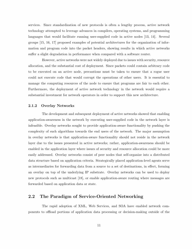
The rapid adoption of XML, Web Services, and SOA have enabled network com-
ponents to offload portions of application data processing or decision-making outside of the
11
traditional data-center. Differences in application data-encoding that once hindered the net-
work’s ability to comprehend true application intent are now described by XML. Routing has
become XML-oriented with the use of functions such as XPath routing [19] to direct traffic
based on XML content. Web Services Security (WS-Security) defines security criteria within
XML Web Services envelopes across service invocations. Further, additional offload capabil-
ities are now possible, such as XML transformation (XSLT) [20] to change XML content as
it traverses the network, and service mediation to enable the interoperability of Web Services
in heterogeneous environments. These have key benefits to SOA as they enable services to be
integrated in a loosely-coupled manner where implementation details of components are hidden
from the requester of the service.
Service-Oriented Networking (SON) is an emerging architecture that enables network
devices to operate at the application layer with ESB-like features such as offloading, protocol
integration, and content-based routing. By adding application-awareness into the network fab-
ric, SON can provide vast gains in overall performance and efficiency and enable the integration
of heterogeneous environments. We refer to this collection of network-resident application-level
operations as SON functions. Among others, SON functionality provides three key benefits:
service virtualization, locality exploitation and improved manageability.
2.2.1 Benefits
Service Virtualization
Service virtualization transparently maps a set of services to the protected back-end
resources that actually provide the service. A SON device can serve as a proxy for actual
services by masking internal resources via XML transformation and routing techniques. The
SON device could also be leveraged to manage security and denial-of-service (DoS) policies for
incoming requests.
Locality Exploitation
By deploying certain functions in the network fabric, SON devices can be provisioned
and customized to handle unique workloads. For example, these systems can be provisioned
with cryptographic hardware assist for SSL or other security functions. Similarly, domain-
specific hardware to optimize XML processing can be installed to offset the cost of processing
Web Services or XML transformation functions. Provisioning and customizing SOA servers can
12
lead to greater efficiencies and can be more cost-effective than provisioning the entire enterprise
with these capabilities. Lastly, a potential performance benefit is gained from exploiting locality
within co-located SON functions. For example, consider a function executing an XSLT schema
transformation while another is performing XPath routing. The two functions can communicate
to avoid parsing the request twice. Locality also has benefits at lower levels of the system, such
as in cache utilization.
Improved Manageability
Offloading function into the network enables centralized, and therefore simplified, man-
agement of the function and corresponding configuration. For example, style sheets, security,
caching and routing policies can all be centrally managed at SON devices versus decentralized
across a cluster of enterprise servers.
2.2.2 Functions
Three examples of SON functions include functional offloading, service integration,
and intelligent routing, each of which is described below: [21].
Functional Offloading
Offloading security-related operations has been a common practice for Internet-based
application environments; this practice is also applicable to document-centric service-oriented
environments. Like the HTTP server, a SON device can be specially provisioned to handle
cryptographic functions. This enables the device to optimize the validation of digital certificates
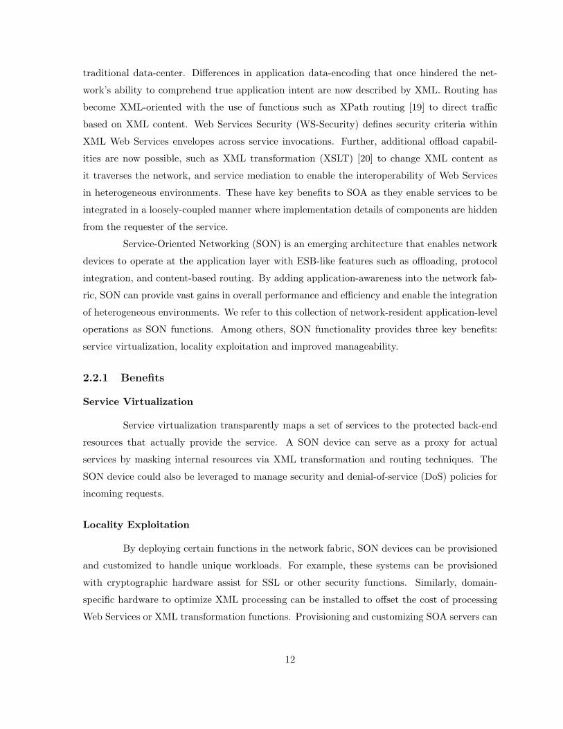
in the context of WS-Security. We illustrate this in Figure 2.1, where the SON appliance
intercepts WS-Security SOAP envelopes, performs the appropriate cryptographic functions,
and forwards the requests on to the service provider.
A SON device can also perform a firewall-like security function to validate service
requests (for example, against a corresponding WSDL or XSD document) before forwarding
them to the enterprise server for processing. These checks would ensure that only well-formed
service requests are forwarded. This prevents DoS attacks and ensures that enterprise servers
are encountering only valid service requests.
The most efficient form of offloading is in full-function offload where the service re-
quest can be satisfied completely within the SON device. Dynamic service response caching, a
13
ServiceProvider
Encrypted &Signed
SOAP/XML
Decrypted & AuthenticatedSOAP/XML
WS-Security:Decryption & Authentication
ServiceOriginator
SON Appliance
Figure 2.1: Example of Functional Offloading
technique that accomplishes this, is most effective for read-mostly interactions where requests
do not update back-end states or databases. For example, service requests that retrieve stock
quotes, where ticker values are updated every five minutes, are well suited for this type of of-
fload. If done correctly, a large proportion of the read traffic can be completely serviced by the
appropriate caching component, thereby reducing the load on enterprise database servers. A
cache policy contains rules that define how results from specified services requests are cached.
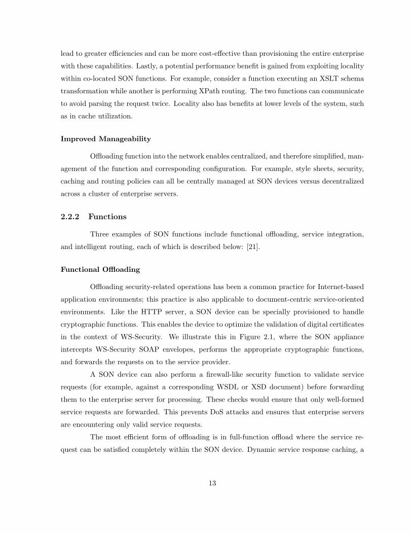
Service Integration
WidgetsRUSServiceProvider
Purchase Order in Widgets, Inc.XML Schema
Purchase Order in WidgetsRUSXML Schema
XSLTransformationWidgets, Inc.
ServiceOriginator
SON Appliance
Figure 2.2: Example of Service Integration
Figure 2.2 illustrates the service integration aspect of the SON device in which a widget
retail store (Widgets, Inc.) is ordering a collection of parts by invoking a service request back
at the home office. The home office has deployed the SON device in the network fabric that
14
chooses the best parts supplier and forwards the service request to that supplier. However, in
this case, the XML schema of Widgets, Inc. is different depending on the chosen supplier. The
SON device is capable of transforming the original order to schemas of participating providers,
in this case WidgetsRUS. Other widget manufacturers would likely require different schemas,
requiring the SON function to apply the appropriate XSLT transformation dependent on the
supplier.
Since the majority of corporate data today exists in mainframe databases, service
integration also provides the ability to interface with existing legacy systems, giving a system
architect more flexibility to migrate towards a service-oriented environment. This increases the
number of service consumers that can take advantage of these programs and data and extends
the reach of SON and SOA further into the enterprise.
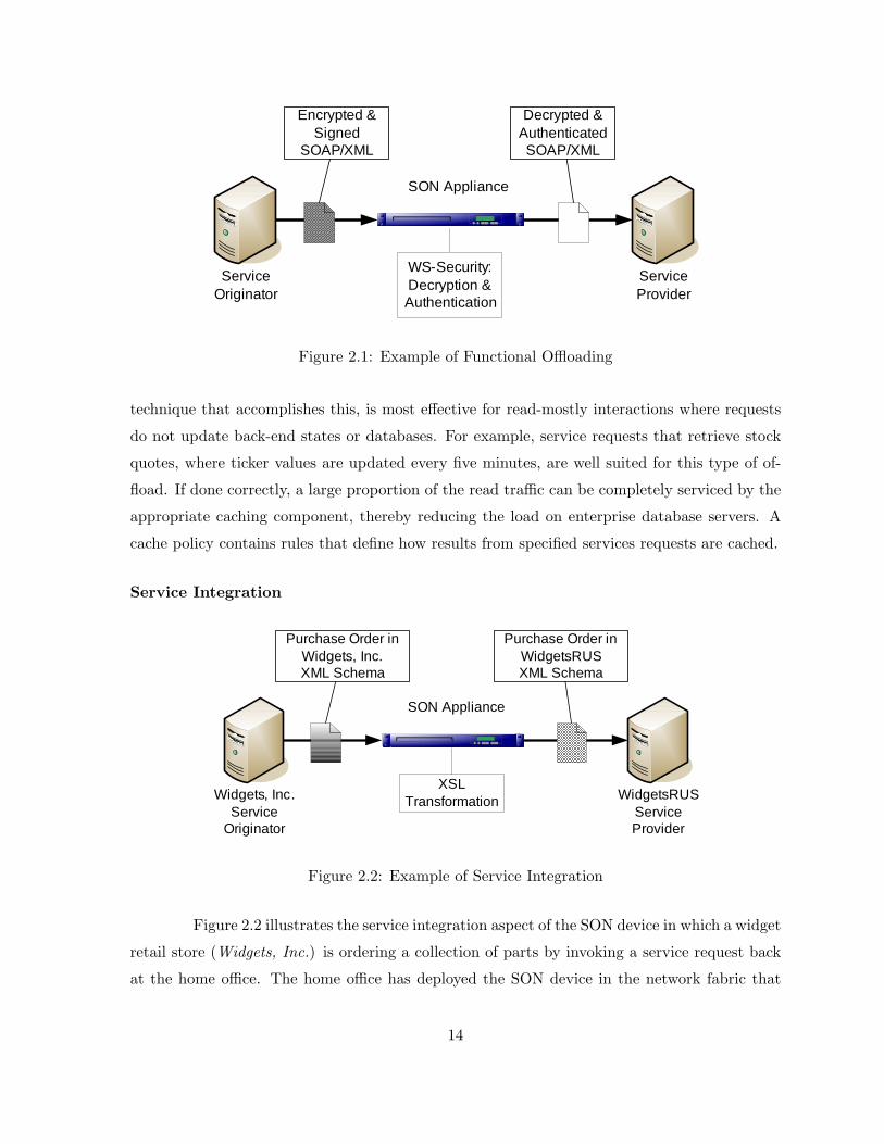
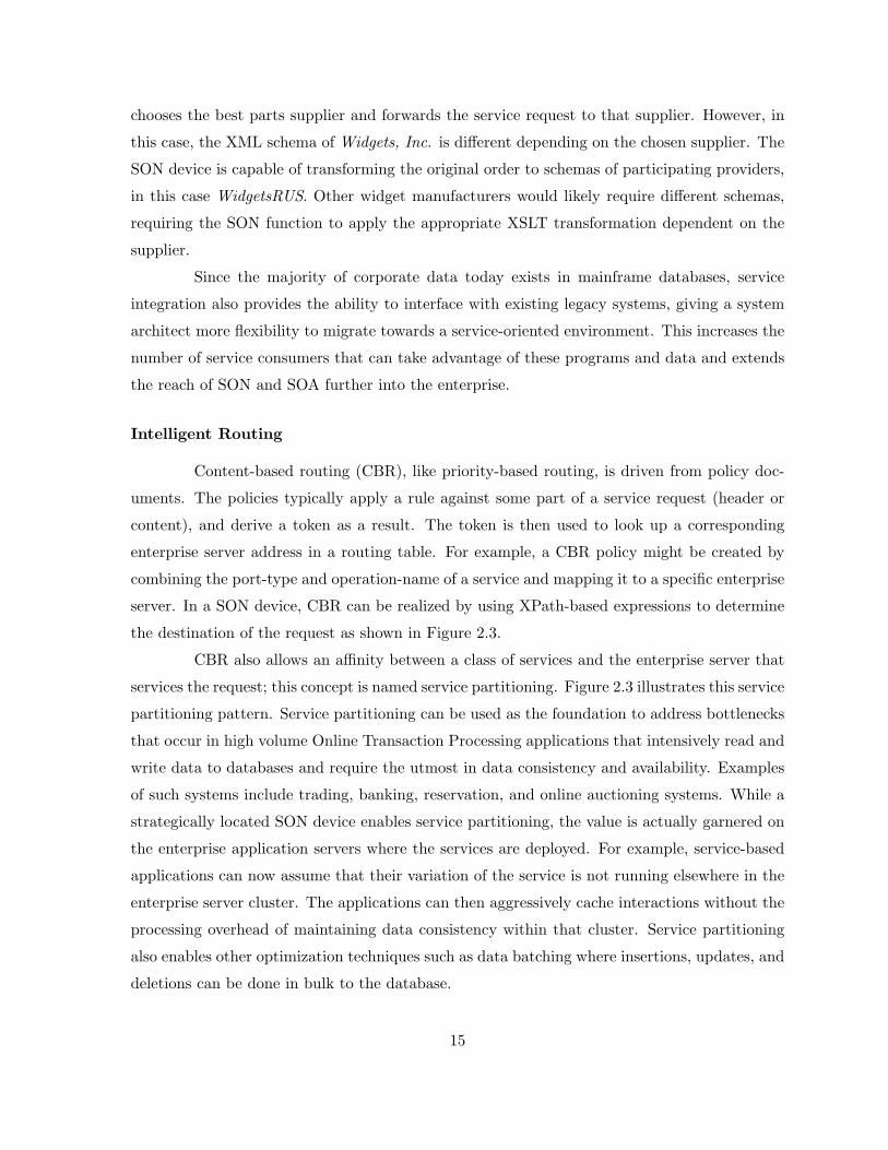
Intelligent Routing
Content-based routing (CBR), like priority-based routing, is driven from policy doc-
uments. The policies typically apply a rule against some part of a service request (header or
content), and derive a token as a result. The token is then used to look up a corresponding
enterprise server address in a routing table. For example, a CBR policy might be created by
combining the port-type and operation-name of a service and mapping it to a specific enterprise
server. In a SON device, CBR can be realized by using XPath-based expressions to determine
the destination of the request as shown in Figure 2.3.
CBR also allows an affinity between a class of services and the enterprise server that
services the request; this concept is named service partitioning. Figure 2.3 illustrates this service
partitioning pattern. Service partitioning can be used as the foundation to address bottlenecks
that occur in high volume Online Transaction Processing applications that intensively read and
write data to databases and require the utmost in data consistency and availability. Examples
of such systems include trading, banking, reservation, and online auctioning systems. While a
strategically located SON device enables service partitioning, the value is actually garnered on
the enterprise application servers where the services are deployed. For example, service-based
applications can now assume that their variation of the service is not running elsewhere in the
enterprise server cluster. The applications can then aggressively cache interactions without the
processing overhead of maintaining data consistency within that cluster. Service partitioning
also enables other optimization techniques such as data batching where insertions, updates, and
deletions can be done in bulk to the database.
15
ServiceProviders
Unclassified Requests
XPathRouting
SON Appliance
Figure 2.3: Example of Intelligent Routing
2.3 Research Challenges in Building SON Devices
We believe that SON is an exciting new research area that can have a dramatic impact
on the design, performance, integration, and management of service-oriented environments.
Therefore, we believe that significant research is needed in the following areas in order to create
an adaptive and robust SON device that can provide the benefits of service-oriented networking
as we have described in this chapter:
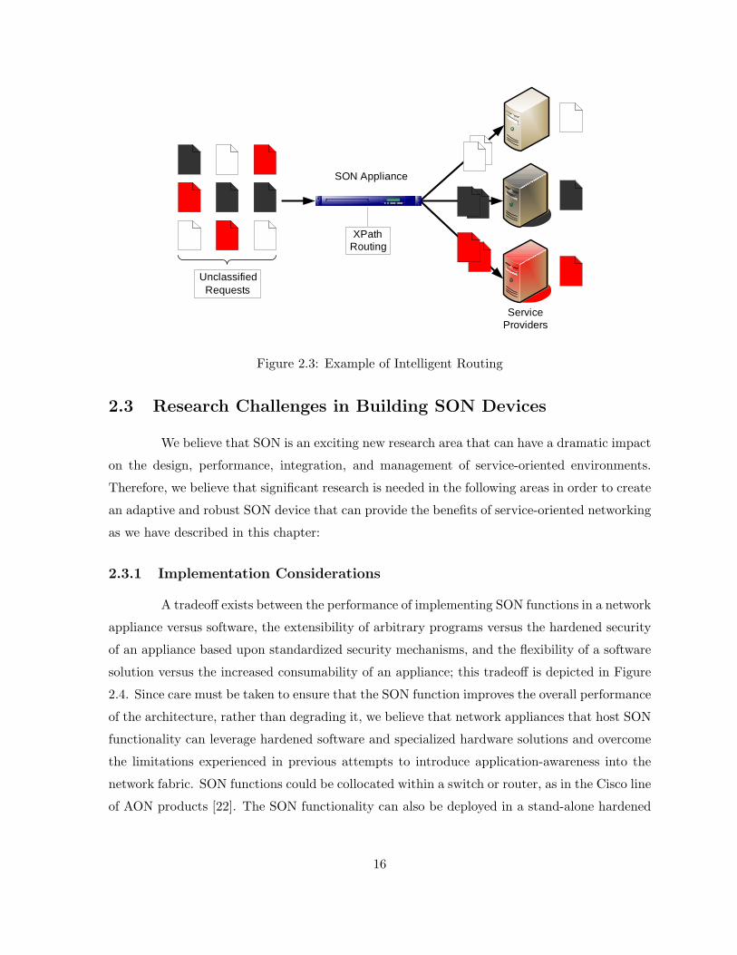
2.3.1 Implementation Considerations
A tradeoff exists between the performance of implementing SON functions in a network
appliance versus software, the extensibility of arbitrary programs versus the hardened security
of an appliance based upon standardized security mechanisms, and the flexibility of a software
solution versus the increased consumability of an appliance; this tradeoff is depicted in Figure
2.4. Since care must be taken to ensure that the SON function improves the overall performance
of the architecture, rather than degrading it, we believe that network appliances that host SON
functionality can leverage hardened software and specialized hardware solutions and overcome
the limitations experienced in previous attempts to introduce application-awareness into the
network fabric. SON functions could be collocated within a switch or router, as in the Cisco line
of AON products [22]. The SON functionality can also be deployed in a stand-alone hardened
16
SecurityExtensibility
AppliancePerformance
Software Performance
Consumability
Flexibility
SON Appliance
Figure 2.4: Comparison of Software and Appliance Approaches
appliance as in several products sold by DataPower, recently acquired by IBM [23].
2.3.2 Robustness
The SON device should scale to support a large number of requests to be processed
concurrently. It should be robust to overload conditions, continuing to prioritize and process
high priority requests and shed low priority requests while operating in an overloaded regime.
Admission control ensures that a server always operates in a stable regime; even in overloaded
conditions, the server can scale and continue to provide differentiated service to its users. In
order for an SON device to provide services that are fair to the requesting users, a policy should
be defined that enumerates the differential treatment that requests are to receive. This policy
should define strategies to prioritize traffic under both normal and overloaded conditions. Since
requests must be classified before they can be prioritized, it is essential in overloaded conditions
that the system can continue to process high priority requests while possibly shedding lower
priority requests. Therefore, fast methods for classifying incoming requests are needed. The
classifications could be based on network layer information or upon information residing within
the XML content. Algorithms for executing XPath expressions on streaming XML such as
QuickXScan [24] could be useful in such situations.
17

2.3.3 Specialized Hardware
One main benefit of SON is that it can leverage specialized hardware, such as hardware-
accelerated cryptographic or XML processing functionality, to enhance the overall performance
of the device. However, the SON device will contain software components that process requests
in conjunction with the available hardware devices. Since these components could block upon
the remote invocation of services, it will be important to ensure an efficient and robust coop-
eration scheme between these hardware and software components exists, as this scheme will be
crucial to the overall stability and performance of the SON device.
2.3.4 Security
As in active networks, SON provides software functionality that will be executed in
the network fabric. However, with the introduction of open standards such as XML and WS-
Security, we believe that SON devices will not suffer from the same security issues as active
networks. The use of XML in network operations raises new research questions regarding how
open standards such as XML and Web Services could be leveraged together in an SON appliance
in order to create a device that is hardened against XML and Web Services-based DoS attacks.
One approach is to leverage well-formedness checking and XML schema validation against all
incoming documents in order to ensure that only valid requests proceed within the device for
further processing.
2.3.5 Resource Allocation
The SON device should be adaptive, changing its underlying execution model to sup-
port different types of software components in order to maximize the efficiency of the system.
We believe that concurrency mechanisms will be a significant component of resource allocation
within a scalable and adaptive SON device. Concurrency mechanisms have a dramatic effect
on the overall performance and efficiency of a device. Internet services are unique because they
require massive concurrency but also block while waiting on unavailable resources. It is this
unique combination of requirements that suggests a hybrid architecture that could be used to
exploit the benefits of different concurrency mechanisms. Models such as the Staged Event-
Driven Architecture (SEDA) [25] could prove useful in building an adaptive resource allocation
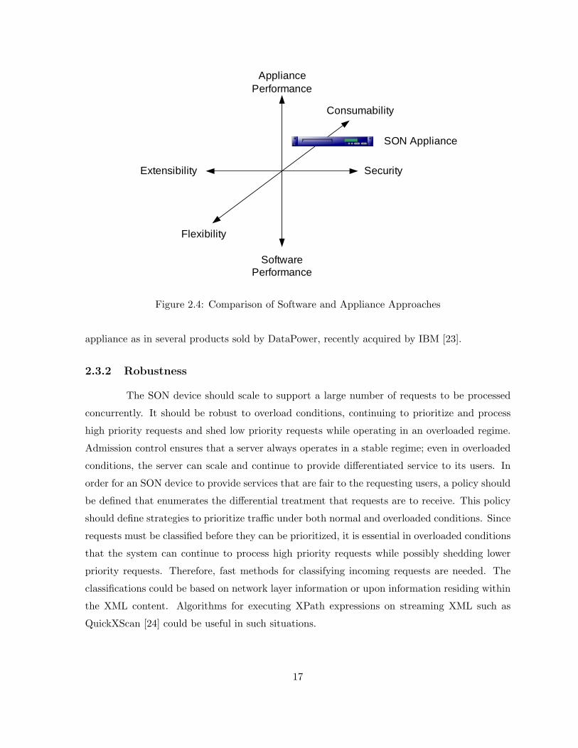
system for an SON device.
SEDA is an architecture that separates functions within applications into stages, which
18
each having its own thread pool and is connected with others as a network of queues in order
to provide the desired application functionality. Admission control is used at each stage, and
adaptive controllers that can modify the thread pool size or the amount of requests that are
processed by each thread (batching) are included. Figure 2.5 (reprinted from [26]) shows how
admission control is performed on requests to a SEDA stage using a response time controller.
Figure 2.5: Example of Adaptive Admission Control: SEDA Response Time Controller
2.4 Research Challenges in Interconnecting SON Devices
The initial work presented here concentrates on enablement technologies that logis-
tically deliver and deploy SON functions manually; however, we look toward the autonomic
configuration and coordination amongst these functions.
2.4.1 Manageability
Specifically, we anticipate that enterprise applications of the future will begin to lever-
age distributed SON deployment patterns where large numbers of SON devices coordinate with
peers using network-wide application-specific policies. Manual configurations are not able to
scale with these environments, nor can they adapt the configuration to dynamic network and
application conditions. For example, a large-scale SON deployment could be leveraged to enable
application-specific multicast. SON devices should coordinate with their peers to determine the
19
appropriate points in the network to perform configuration changes based on prevailing network
and application conditions.
2.4.2 Resource Allocation
Also in this light, we envision that SON devices will need to collaborate to effectively
allocate their computing resources in order to effect the aforementioned application-specific
service policies. Our contributions in this area are discussed in Chapters 3 & 4; however, there
are some initial efforts towards collaborative resource allocation present in the literature that
we review below.
Kallitsis et. al introduce a pricing model that ensures efficient resource allocation
that provides guaranteed quality of service while maximizing profit in multiservice networks
[27]. Specifically, they examine a centralized dynamic allocation policy that relies on online
measurements while operating each service class under a probabilistic bound delay constraint.
In [28], Kallitsis et. al continue their previous work regarding optimal resource allo-
cation of next generation network services under a flat pricing scheme and quality of service
policies. They present a complete framework that dynamically allocates resources when it is
required. To in order to effect that, they apply an online traffic estimator and monitor traffic
changes using an Exponentially Weighted Moving Average control chart; therefore, the profit
maximization of the provider is done efficiently since their optimization algorithm will only
solve the problem when a traffic shift is detected that would yield a significant change in the
allocation.
Finally, Kallitsis et. al present a distributed algorithm that dynamically solves an
optimization problem so as to allocate the available resources to delay-sensitive services offered
in a SON [29]. Somewhat similar to the work presented in Chapter 4, pricing is used to
differentiate services based on their quality-of-service requirements. Their performance metric
is the end-to-end delay that a service class would experience in the network; a deterministic
upper bound of end-to-end delay is derived from the theory of network calculus. The moving
average control scheme adopted for capturing traffic shifts in real time makes their solution
react adaptively to traffic alterations. Finally, they evaluated their system using real network
traces generated from application layer instant messaging services.
20
2.5 Conclusions
The emergence of XML along with advances in hardware, software, and networking
technologies serves as the catalyst for the development of service-oriented networking. SON
devices are application-aware network components that are able to understand data encoded in
XML and act upon that data intelligently to make routing decisions, enforce QoS or security
policies, or transform the data into an alternate representation. Using design patterns such as
functional offloading, service integration, and intelligent routing, SON can enable service vir-
tualization, increase manageability and exploit locality. In this chapter, we have described the
motivation behind SON, the potential benefits of introducing application-aware network devices
into service-oriented architectures, and discussed research challenges in the development and in-
terconnection of SON appliances. We believe that SON provides exciting new multidisciplinary
research opportunities in service-oriented computing, hardware, software, and networking that
could have dramatic effects on the development of emerging network services.
21
Chapter 3
Large-Scale Service-Oriented
Systems
The enterprise service bus acts as the integration and communications platform for
connecting service consumers and providers. It is often desirable to have multiple ESB deploy-
ments federate with one another to provide a distributed integration platform that promotes
the reuse of services within and across enterprises. However, the existing solutions to federate
ESBs are limited by their inflexibility to change and inability to scale. In this chapter, we pro-
pose the enablement of a federation of ESBs via a distributed service registry that distributes
policy-appropriate service metadata to federation members. We provide a high-level descrip-
tion of two protocols that maintain the state of the distributed registry within and between
autonomous federations. We argue that these application of a distributed service registry and
the enabling protocols is a novel application of existing technology that creates a robust, scal-
able, and flexible federation of ESBs that is needed in the next generation of large-scale SOA
deployments.
3.1 Introduction & Motivation
As a critical infrastructural component of service-oriented architectures, the ESB acts
as the integration and communications platform for connecting service consumers and providers
[30]. As such, the ESB is responsible for, along with many other functions, the enforcement of
policies, routing of service requests, and performing content and/or transport protocol trans-
formation.
22
As the number of services in an organization increases, the need for a service discovery
and governance platform arises. The service registry enables consumers to find available services
and providers to advertise available service instances. The registry can optionally serve as a
repository for governance metadata, policy documents, and XML schemas.
Instantiating the ESB in a message-oriented middleware product, along with deploying
a service registry, provides an intuitive solution towards implementing a small to medium-size
SOA. However, recent market trends show that SOA is being rapidly adopted; therefore, strate-
gies for creating more large-scale deployments are needed. A typical approach to transitioning
from a moderate-scale to a large-scale SOA deployment is to “scale-up”; that is, leave the
topology of the architecture fundamentally unaltered while adding additional resources to the
individual architectural components. “Scaling-out” yields a distributed approach to the large-
scale problem that involves altering the topology of interconnected architectural components.
Furthermore, we argue that the rapid adoption of SOA is causing an increase in the number
of business-to-business transactions between autonomous SOA deployments. Primarily for rea-
sons of governance, these types of interactions exemplify the need for a large-scale distributed
ESB; we refer to such a system as a federation of enterprise service buses.
In a federation of ESBs, the primary problem is to appropriately disseminate infor-
mation throughout nodes that comprise the ESB to enable policy-driven service discovery and
routing. We propose that a distributed service registry is a scalable and robust approach to
enabling federations of enterprise service buses. The distributed service registry is hierarchi-
cal in nature and is maintained by two protocols that synchronize relevant service metadata
amongst ESB deployments as appropriate under defined business policies. There are three main
advantages to our proposal over existing approaches:
• We enable the federation of ESB deployments within an enterprise in a flexible and scalable
manner.
• The distributed service registry and the supporting protocol allow our solution to adapt
autonomically to dynamic network and service conditions.
• This architecture provides the capability to support on-demand techniques such as fast
failover or priority-based load shedding in an autonomic fashion.
The remainder of the chapter is structured as follows: in the following section, we
review existing approaches to the ESB federation problem. In Section 3.3, we explicitly propose
23
our architecture that enables the dynamic and scalable federation of ESBs. In Section 3.4, we
present an overview of the first of two protocols that maintains the consistency and availability
of service metadata within an autonomous federation. In Section 3.5, we present the second
protocol that is responsible for the maintenance of interconnections of autonomous federations.
3.2 Current Approaches to ESB Federation
Currently, there are three approaches to addressing the problem of policy-driven ser-
vice metadata dissemination: manual configuring interconnections, deploying a broker ESB,
and utilizing a centralized registry across or between enterprises.
3.2.1 Manual Configuration
One way of federating ESBs is by manually configuring functionality within an ESB
that serves as a “proxy” to other ESBs in the federation. For each service that is managed by
a remote ESB, a mediation must be defined that selects appropriate requests to be forwarded
to the remote ESB, performs necessary content/protocol transformations, and subsequently
forwards the request onto the remote ESB. Matching mediations must exist on remote ESBs
in order to support bidirectional communication in this case. Since this configuration must be
done manually by a systems administrator at each ESB, the configuration of such a solution
is tedious and prone to error (for S services and N ESBs, there are possibly SN proxies to
be configured). There is also no mechanism to change the properties of this mediation based
on changes in network or service availability. Manual configuration allows basic federation of
multiple ESBs; however, this is an inflexible and impractical solution for large scale enterprises.
3.2.2 Broker ESB
Rather than statically defining the routing mediations at each ESB, a separate ESB
called a “broker” ESB can be deployed, whose sole function is to implement the requisite
mediations to support federation. This helps to consolidate the many different mediations that
might exist in the manually configured solution described above into a single ESB. However, this
consolidation is still dependent on a systems administrator to manually define the mediations
required for each service (in this case, the number of proxies to be configured is minimized
to S). Since there is no mechanism to update the mediation metadata based on dynamic
24
service availability, the broker ESB solution is inflexible. The broker ESB then becomes the
architectural bottleneck, which introduces issues with scalability and fault tolerance.
3.2.3 Centralized Registry
The final known approach is to deploy a centralized registry for the entire enterprise.
When ESBs need to route service requests to other ESBs within the SOA, they would consult
the registry at runtime to make a forwarding decision based on the current location of a service
instance, thus addressing the manual configuration concerns raised by the previous solutions (as
with the broker ESB, the number of entries in the centralized registry is equal to the number of
services S). However, centralizing all service metadata and status into a single registry forces
the registry to be the architectural bottleneck in such a federated system, thus causing concerns
with system performance, scalability, and fault tolerance. The centralized registry is ideal from
the standpoint of the consolidation of service information, but is infeasible in many realistic
business scenarios due to business-to-business interactions, disparate geographical locations,
and limitations imposed by business structures. Today, manual configuration of the centralized
registry is required to insert/update/delete service metadata, which limits the flexibility of this
solution.
3.3 Federation Architecture
The overarching goal of ESB federation is to provide a logically centralized (at an
appropriate scope) integration platform across different geographic and business boundaries;
that is, the topology formed by the federation of ESB deployments should align directly to the
structure of entities within an enterprise. Examples of federated ESB topologies that align with
common business structures are presented in [31].
Figure 3.1 shows the logical topology of a hub/spoke federated ESB. This type of
topology directly aligns with the Store/Branch business structure described in [31] and forces
all service routing to be done through the hub ESB deployment.
Figure 3.2 shows the logical topology of a directly-connected federated ESB. In this
topology, all ESB deployments are connected directly to one another, so that service requests
that are routed within the federation pass directly from the source ESB to destination ESB. This
type of topology directly aligns with the Multiple Geographies & Multiple Business Divisions
business structures described in [31].
25

Figure 3.1: Example Topology of Multiple ESB Deployments - Hub & Spokes
Figure 3.2: Example Topology of Multiple ESB Deployments - Peer Business Divisions
A natural extension of the intra-federation topology is interconnecting multiple fed-
erations, as shown in Figure 3.3. There is a practical need for interconnected federations; the
need arises, for example, in business-to-business environments, in which separate enterprises
must interact to provide a service to each other or to create a composite service to be offered
to an external customer. The same need arises within a single but large enterprise (e.g., in
an e-government setting), when the enterprise itself is organized as multiple, autonomous, and
heterogeneous federations of ESBs.
A key concept in our proposal is the notion that the amount of service registry data
that is shared with a federation member is configurable via policy; we refer to this concept
as policy-based service advertisement. For example, in the hub & spoke case, it is desirable
for a spoke to share appropriate service information (as defined by policy) with the hub ESB,
and share no service information with any other spoke ESB. Policy-based service advertise-
ment allows different members of the federation to have different views of hosted services at
a particular federation member. We envision that certain services should only be exposed to
certain federation members, and that it may be desirable to allow or disallow the advertisement
of particular services. While certainly related, we believe that the appropriate distribution of
26
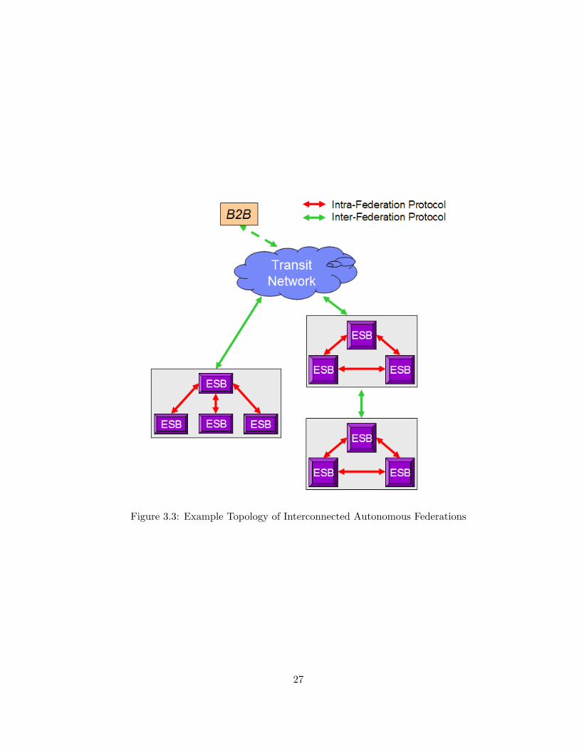
Figure 3.3: Example Topology of Interconnected Autonomous Federations
27
policy documents is an orthogonal problem to the one we are addressing and is therefore outside
the scope of this manuscript.
Our method to achieve a dynamic and scalable federation of enterprise service buses
is based upon the concept of a distributed service registry. Federation members create a dis-
tributed service registry by sending policy-based service advertisements to peer members. Each
federation member will have its own (possibly unique) converged view of all routable service
endpoints in the federation, which it will use in making routing/forwarding decisions. This
model contrasts with the centralized registry solution described in Section 3.2; notably, the
distributed nature of the registry allows it to overcome the scalability and robustness concerns
that exist with a centralized solution. In order to allow the federation members to distribute
service state amongst themselves, protocols are needed that implement the policy-based service
advertisements in an automated fashion.
3.3.1 Related Work
There are several previous attempts that have been made towards developing federated
service discovery architectures that are based on service registries. The authors of [32] propose
defining a topology for collaborative service discovery, and subsequently floods the topology with
the discovery query, and all nodes respond to the client with the results. A similar proposal
is presented in [33], where UX servers are part of a federation, and a minimum spanning tree
is found in order to flood queries if an initial lookup returns null. However in both of these
proposals, flooding is required and such systems are known not to be scalable.
There are several proposals for distributed service discovery based upon distributed
hash tables (DHT) and P2P technologies. [34] proposes the integration of distributed hash
tables with UDDI registries to enable a larger distributed registry; however, they do not consider
governance issues in a cross-domain system in the proposal. The authors of [35] present the
use of DHT as a way to enable a scalable service discovery platform for Grid environments.
In [36], a P2P network is used to interconnect registries using a layered approach. Clients
issue queries about available services (that meet their desired semantics and QoS) to a gateway
layer, that is responsible for the translation of the query into the ontologies of the different
types of ontologies supported at the different registries within the federation, and then passes
the query off to a routing layer that transmits the query onto the appropriate registry. Finally,
[37] focuses on the discovery component of the service composition problem; they utilize Pastry
as a P2P service overlay to find services that can be used in a larger composition. A proposal
28
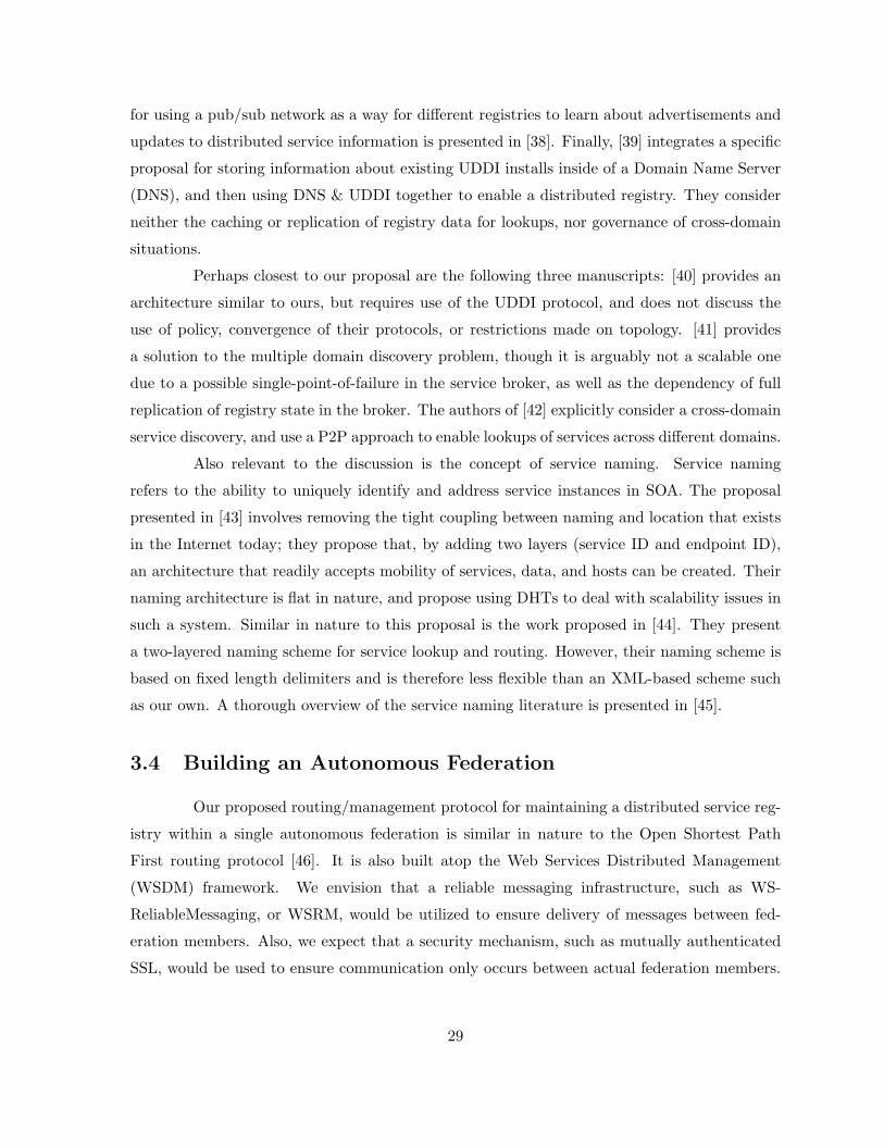
for using a pub/sub network as a way for different registries to learn about advertisements and
updates to distributed service information is presented in [38]. Finally, [39] integrates a specific
proposal for storing information about existing UDDI installs inside of a Domain Name Server
(DNS), and then using DNS & UDDI together to enable a distributed registry. They consider
neither the caching or replication of registry data for lookups, nor governance of cross-domain
situations.
Perhaps closest to our proposal are the following three manuscripts: [40] provides an
architecture similar to ours, but requires use of the UDDI protocol, and does not discuss the
use of policy, convergence of their protocols, or restrictions made on topology. [41] provides
a solution to the multiple domain discovery problem, though it is arguably not a scalable one
due to a possible single-point-of-failure in the service broker, as well as the dependency of full
replication of registry state in the broker. The authors of [42] explicitly consider a cross-domain
service discovery, and use a P2P approach to enable lookups of services across different domains.
Also relevant to the discussion is the concept of service naming. Service naming
refers to the ability to uniquely identify and address service instances in SOA. The proposal
presented in [43] involves removing the tight coupling between naming and location that exists
in the Internet today; they propose that, by adding two layers (service ID and endpoint ID),
an architecture that readily accepts mobility of services, data, and hosts can be created. Their
naming architecture is flat in nature, and propose using DHTs to deal with scalability issues in
such a system. Similar in nature to this proposal is the work proposed in [44]. They present
a two-layered naming scheme for service lookup and routing. However, their naming scheme is
based on fixed length delimiters and is therefore less flexible than an XML-based scheme such
as our own. A thorough overview of the service naming literature is presented in [45].
3.4 Building an Autonomous Federation
Our proposed routing/management protocol for maintaining a distributed service reg-
istry within a single autonomous federation is similar in nature to the Open Shortest Path
First routing protocol [46]. It is also built atop the Web Services Distributed Management
(WSDM) framework. We envision that a reliable messaging infrastructure, such as WS-
ReliableMessaging, or WSRM, would be utilized to ensure delivery of messages between fed-
eration members. Also, we expect that a security mechanism, such as mutually authenticated
SSL, would be used to ensure communication only occurs between actual federation members.
29
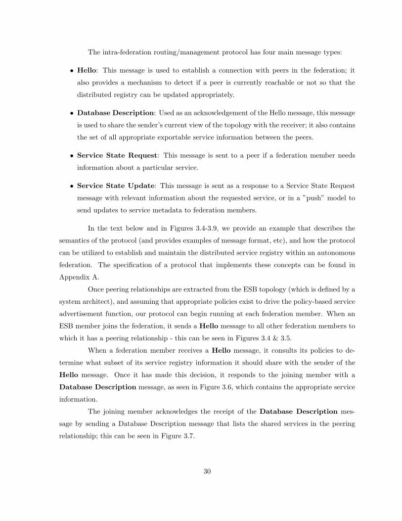
The intra-federation routing/management protocol has four main message types:
• Hello: This message is used to establish a connection with peers in the federation; it
also provides a mechanism to detect if a peer is currently reachable or not so that the
distributed registry can be updated appropriately.
• Database Description: Used as an acknowledgement of the Hello message, this message
is used to share the sender’s current view of the topology with the receiver; it also contains
the set of all appropriate exportable service information between the peers.
• Service State Request: This message is sent to a peer if a federation member needs
information about a particular service.
• Service State Update: This message is sent as a response to a Service State Request
message with relevant information about the requested service, or in a ”push” model to
send updates to service metadata to federation members.
In the text below and in Figures 3.4-3.9, we provide an example that describes the
semantics of the protocol (and provides examples of message format, etc), and how the protocol
can be utilized to establish and maintain the distributed service registry within an autonomous
federation. The specification of a protocol that implements these concepts can be found in
Appendix A.
Once peering relationships are extracted from the ESB topology (which is defined by a
system architect), and assuming that appropriate policies exist to drive the policy-based service
advertisement function, our protocol can begin running at each federation member. When an
ESB member joins the federation, it sends a Hello message to all other federation members to
which it has a peering relationship - this can be seen in Figures 3.4 & 3.5.
When a federation member receives a Hello message, it consults its policies to de-
termine what subset of its service registry information it should share with the sender of the
Hello message. Once it has made this decision, it responds to the joining member with a
Database Description message, as seen in Figure 3.6, which contains the appropriate service
information.
The joining member acknowledges the receipt of the Database Description mes-
sage by sending a Database Description message that lists the shared services in the peering
relationship; this can be seen in Figure 3.7.
30
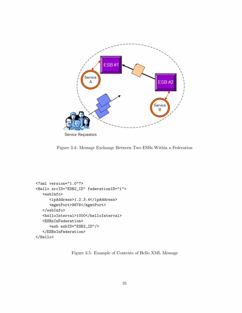
Figure 3.4: Message Exchange Between Two ESBs Within a Federation
<?xml version="1.0"?><Hello srcID="ESB2_ID" federationID="1">
<esbInfo><ipAddress>1.2.3.4</ipAddress><mgmtPort>9876</mgmtPort>
</esbInfo><helloInterval>1000</helloInterval><ESBsInFederation>
<esb esbID="ESB2_ID"/></ESBsInFederation>
</Hello>
Figure 3.5: Example of Contents of Hello XML Message
31
<?xml version="1.0"?><DatabaseDescription srcID="ESB1_ID" federationID="1">
<ESBsInFederation><esb esbID="ESB1_ID"/><esb esbID="ESB2_ID"/>
</ESBsInFederation><services>
<service id="A" esb="ESB1_ID"><ipAddress>1.2.3.100</ipAddress><port>80</port><protocol type="SOAP/HTTP">
<url>http://1.2.3.100:80/someService/a</url><https>false</https>
</protocol></service>
</services></DataBaseDescription>
Figure 3.6: Example of Contents of Database Description XML Message
Hello messages are periodically exchanged with peers in a ”heartbeat” fashion to
ensure connectivity exists between federation members. If a particular federation member
needs information about a particular service, it sends a Service State Request message to a
peer; the peer responds with a Service State Update message with the requested information.
The Service State Update message provides an automated mechanism for the protocol to
dynamically update the distributed registry amongst federation members. This message type
could be used to enable autonomic functionality like fast-failover. In this case, the Service
State Update messages sent would cause the distributed registry to converge to a new state,
causing a new endpoint to be chosen when a routing decision is made for a relevant service
request. Figure 3.8 shows an example of a Service State Update message being sent to a
peer ESB to inform the peer that a port number is changing for a routable service proxy.
3.4.1 Service Request Forwarding
In this section, we have shown examples of how the routing/management protocol
is used to synchronize the state of the distributed registry within a federation. Figure 3.9
shows how the distributed registry enables the routing/forwarding of service requests within a
federation. When a request is received, either directly from a service requestor or forwarded
32
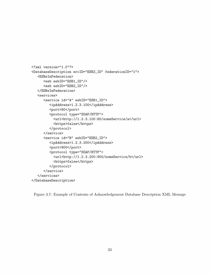
<?xml version="1.0"?><DatabaseDescription srcID="ESB2_ID" federationID="1">
<ESBsInFederation><esb esbID="ESB1_ID"/><esb esbID="ESB2_ID"/>
</ESBsInFederation><services>
<service id="A" esbID="ESB1_ID"><ipAddress>1.2.3.100</ipAddress><port>80</port><protocol type="SOAP/HTTP"><url>http://1.2.3.100:80/someService/a</url><https>false</https>
</protocol></service><service id="B" esbID="ESB2_ID">
<ipAddress>1.2.3.200</ipAddress><port>900</port><protocol type="SOAP/HTTP"><url>http://1.2.3.200:900/someService/b</url><https>false</https>
</protocol></service>
</services></DatabaseDescription>
Figure 3.7: Example of Contents of Acknowledgement Database Description XML Message
33
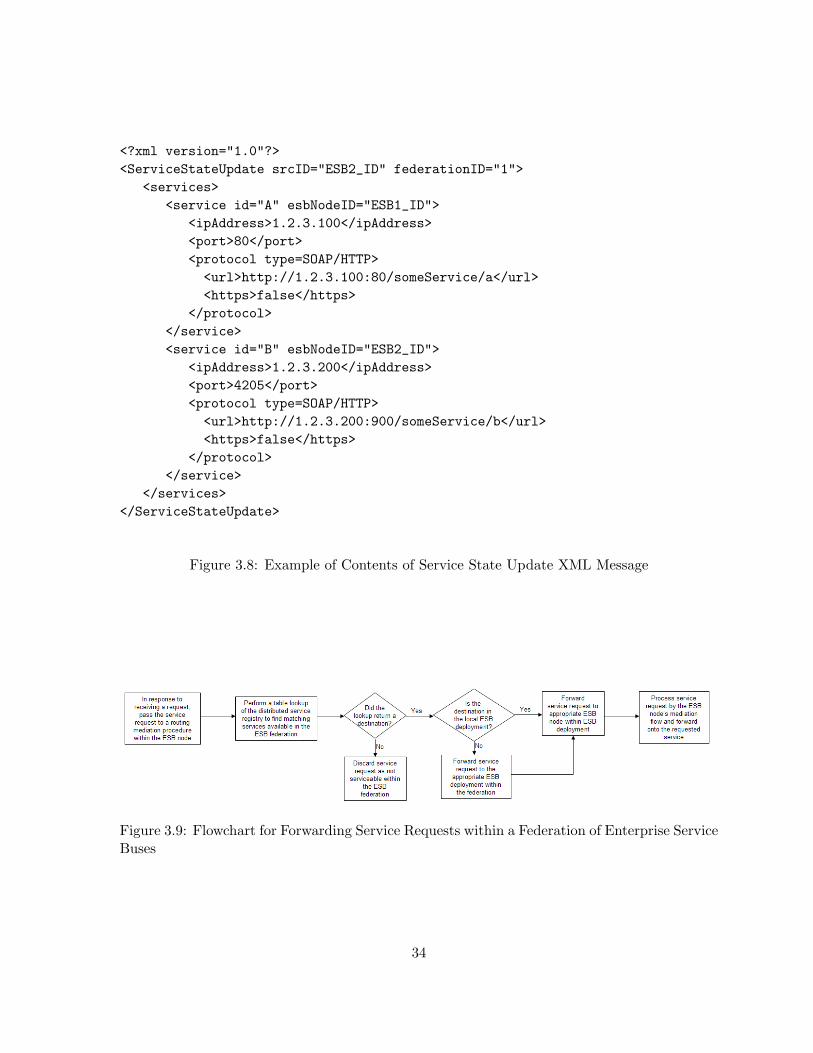
<?xml version="1.0"?><ServiceStateUpdate srcID="ESB2_ID" federationID="1">
<services><service id="A" esbNodeID="ESB1_ID">
<ipAddress>1.2.3.100</ipAddress><port>80</port><protocol type=SOAP/HTTP><url>http://1.2.3.100:80/someService/a</url><https>false</https>
</protocol></service><service id="B" esbNodeID="ESB2_ID">
<ipAddress>1.2.3.200</ipAddress><port>4205</port><protocol type=SOAP/HTTP><url>http://1.2.3.200:900/someService/b</url><https>false</https>
</protocol></service>
</services></ServiceStateUpdate>
Figure 3.8: Example of Contents of Service State Update XML Message
Figure 3.9: Flowchart for Forwarding Service Requests within a Federation of Enterprise ServiceBuses
34
from another ESB node in the deployment, it is passed to a routing mediation. This routing
mediation determines the destination for this request by consulting the local service registry
along with its locally defined service connections. If this is the appropriate ESB node for the
request (i.e. the service instance can be directly reached through a mediation flow at this
node), the request is passed to the mediation flow for processing and eventually passed onto the
service instance. If the service request can not be serviced (or should not be serviced, according
to policy) within this ESB deployment, the routing mediation then consults the distributed
registry for matching service instances available in the federation to decide where to send the
request. If an appropriate destination is reachable in the federation, the request is sent to
the correct ESB deployment and then forwarded onto the appropriate ESB node that provides
connectivity for the particular service being requested. Otherwise, the request is discarded as
not being serviceable within the federation.
3.5 Interconnecting Autonomous Federations
Our proposed routing/management protocol for maintaining a distributed service reg-
istry between autonomous federations is similar in nature to the Border Gateway Protocol [47].
As with the intra-federation protocol, it is also built atop the WSDM framework. Again, we
envision that a reliable messaging infrastructure would be utilized to ensure delivery of mes-
sages between boundary nodes of federations. Also, we expect that a security mechanism, such
as mutually authenticated SSL, would be used to ensure that communication solely occurs
between actual boundary nodes.
The inter-federation routing/management protocol has four main message types:
• Open: This is the first message exchanged between two peers. It is used to establish a
connection with peers in the federation; it also provides a mechanism to detect if a peer
is currently reachable so that the distributed registry can be updated appropriately. It
may also be used in the case that an individual node suffers failure in order to request a
current update of the distributed registry including any changes that occurred during the
failure.
• KeepAlive: This message is used to maintain “reachibility” between peers.
• Update: This message is used to convey routing information between peers. It is used
to share the sender’s current view of the topology with the receiver, e.g., to advertise new
35
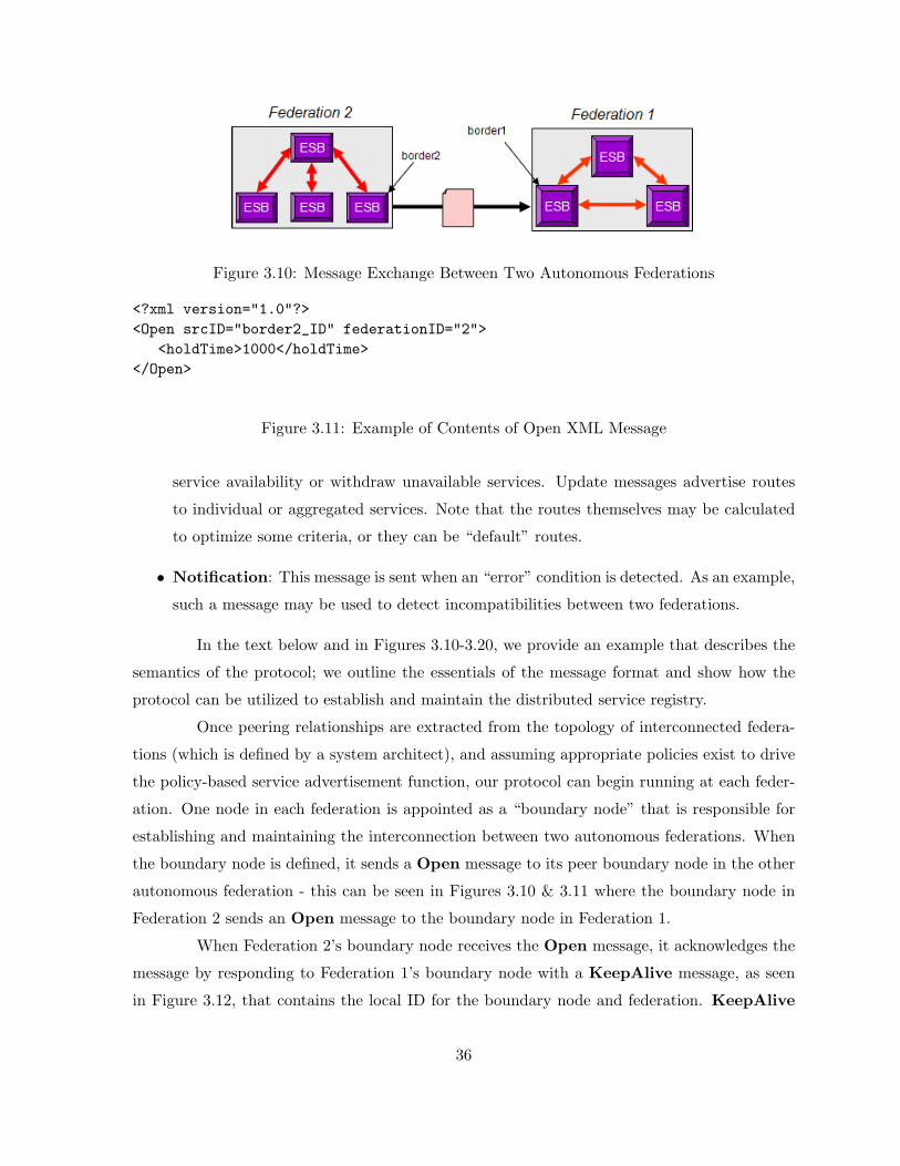
Figure 3.10: Message Exchange Between Two Autonomous Federations
<?xml version="1.0"?><Open srcID="border2_ID" federationID="2">
<holdTime>1000</holdTime></Open>
Figure 3.11: Example of Contents of Open XML Message
service availability or withdraw unavailable services. Update messages advertise routes
to individual or aggregated services. Note that the routes themselves may be calculated
to optimize some criteria, or they can be “default” routes.
• Notification: This message is sent when an “error” condition is detected. As an example,
such a message may be used to detect incompatibilities between two federations.
In the text below and in Figures 3.10-3.20, we provide an example that describes the
semantics of the protocol; we outline the essentials of the message format and show how the
protocol can be utilized to establish and maintain the distributed service registry.
Once peering relationships are extracted from the topology of interconnected federa-
tions (which is defined by a system architect), and assuming appropriate policies exist to drive
the policy-based service advertisement function, our protocol can begin running at each feder-
ation. One node in each federation is appointed as a “boundary node” that is responsible for
establishing and maintaining the interconnection between two autonomous federations. When
the boundary node is defined, it sends a Open message to its peer boundary node in the other
autonomous federation - this can be seen in Figures 3.10 & 3.11 where the boundary node in
Federation 2 sends an Open message to the boundary node in Federation 1.
When Federation 2’s boundary node receives the Open message, it acknowledges the
message by responding to Federation 1’s boundary node with a KeepAlive message, as seen
in Figure 3.12, that contains the local ID for the boundary node and federation. KeepAlive
36
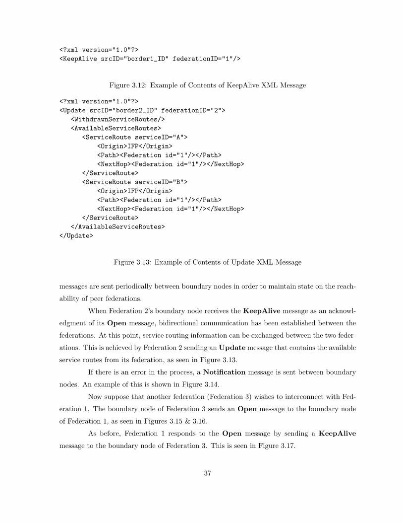
<?xml version="1.0"?><KeepAlive srcID="border1_ID" federationID="1"/>
Figure 3.12: Example of Contents of KeepAlive XML Message
<?xml version="1.0"?><Update srcID="border2_ID" federationID="2">
<WithdrawnServiceRoutes/><AvailableServiceRoutes>
<ServiceRoute serviceID="A"><Origin>IFP</Origin><Path><Federation id="1"/></Path><NextHop><Federation id="1"/></NextHop>
</ServiceRoute><ServiceRoute serviceID="B">
<Origin>IFP</Origin><Path><Federation id="1"/></Path><NextHop><Federation id="1"/></NextHop>
</ServiceRoute></AvailableServiceRoutes>
</Update>
Figure 3.13: Example of Contents of Update XML Message
messages are sent periodically between boundary nodes in order to maintain state on the reach-
ability of peer federations.
When Federation 2’s boundary node receives the KeepAlive message as an acknowl-
edgment of its Open message, bidirectional communication has been established between the
federations. At this point, service routing information can be exchanged between the two feder-
ations. This is achieved by Federation 2 sending an Update message that contains the available
service routes from its federation, as seen in Figure 3.13.
If there is an error in the process, a Notification message is sent between boundary
nodes. An example of this is shown in Figure 3.14.
Now suppose that another federation (Federation 3) wishes to interconnect with Fed-
eration 1. The boundary node of Federation 3 sends an Open message to the boundary node
of Federation 1, as seen in Figures 3.15 & 3.16.
As before, Federation 1 responds to the Open message by sending a KeepAlive
message to the boundary node of Federation 3. This is seen in Figure 3.17.
37
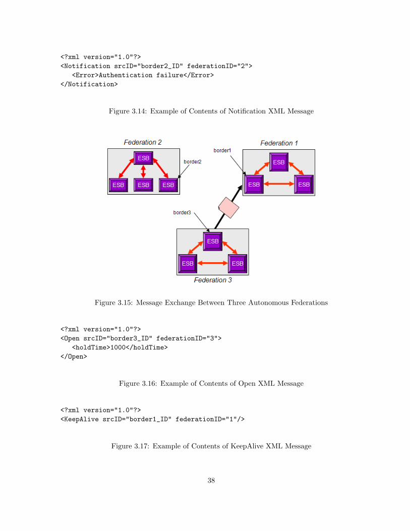
<?xml version="1.0"?><Notification srcID="border2_ID" federationID="2">
<Error>Authentication failure</Error></Notification>
Figure 3.14: Example of Contents of Notification XML Message
Figure 3.15: Message Exchange Between Three Autonomous Federations
<?xml version="1.0"?><Open srcID="border3_ID" federationID="3">
<holdTime>1000</holdTime></Open>
Figure 3.16: Example of Contents of Open XML Message
<?xml version="1.0"?><KeepAlive srcID="border1_ID" federationID="1"/>
Figure 3.17: Example of Contents of KeepAlive XML Message
38
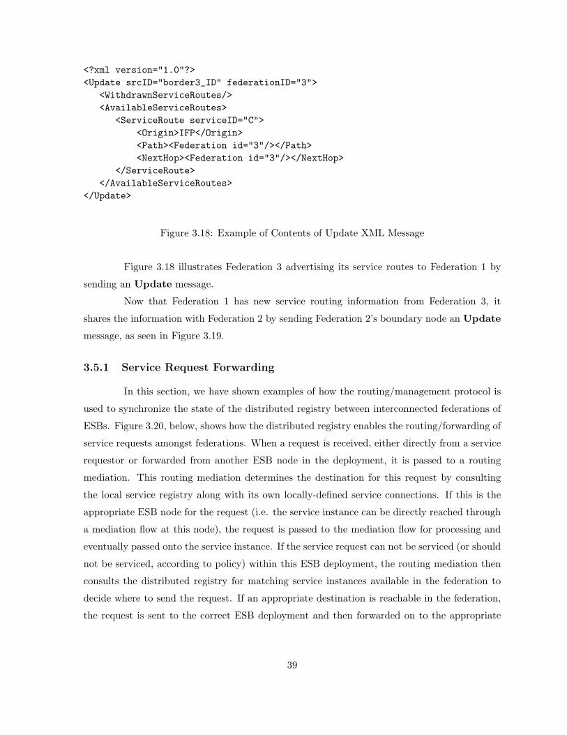
<?xml version="1.0"?><Update srcID="border3_ID" federationID="3">
<WithdrawnServiceRoutes/><AvailableServiceRoutes>
<ServiceRoute serviceID="C"><Origin>IFP</Origin><Path><Federation id="3"/></Path><NextHop><Federation id="3"/></NextHop>
</ServiceRoute></AvailableServiceRoutes>
</Update>
Figure 3.18: Example of Contents of Update XML Message
Figure 3.18 illustrates Federation 3 advertising its service routes to Federation 1 by
sending an Update message.
Now that Federation 1 has new service routing information from Federation 3, it
shares the information with Federation 2 by sending Federation 2’s boundary node an Update
message, as seen in Figure 3.19.
3.5.1 Service Request Forwarding
In this section, we have shown examples of how the routing/management protocol is
used to synchronize the state of the distributed registry between interconnected federations of
ESBs. Figure 3.20, below, shows how the distributed registry enables the routing/forwarding of
service requests amongst federations. When a request is received, either directly from a service
requestor or forwarded from another ESB node in the deployment, it is passed to a routing
mediation. This routing mediation determines the destination for this request by consulting
the local service registry along with its own locally-defined service connections. If this is the
appropriate ESB node for the request (i.e. the service instance can be directly reached through
a mediation flow at this node), the request is passed to the mediation flow for processing and
eventually passed onto the service instance. If the service request can not be serviced (or should
not be serviced, according to policy) within this ESB deployment, the routing mediation then
consults the distributed registry for matching service instances available in the federation to
decide where to send the request. If an appropriate destination is reachable in the federation,
the request is sent to the correct ESB deployment and then forwarded on to the appropriate
39
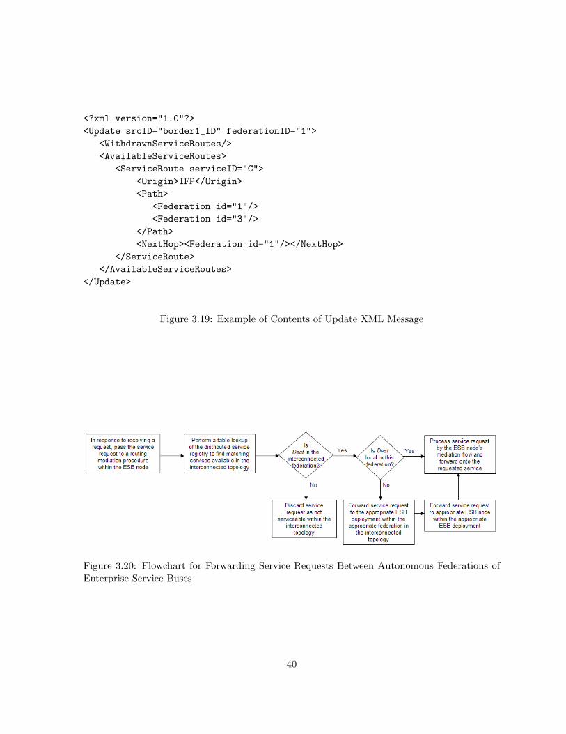
<?xml version="1.0"?><Update srcID="border1_ID" federationID="1">
<WithdrawnServiceRoutes/><AvailableServiceRoutes>
<ServiceRoute serviceID="C"><Origin>IFP</Origin><Path>
<Federation id="1"/><Federation id="3"/>
</Path><NextHop><Federation id="1"/></NextHop>
</ServiceRoute></AvailableServiceRoutes>
</Update>
Figure 3.19: Example of Contents of Update XML Message
Figure 3.20: Flowchart for Forwarding Service Requests Between Autonomous Federations ofEnterprise Service Buses
40

ESB node that provides connectivity for the particular service being requested. Otherwise, the
routing mediation then consults the distributed registry for matching service instances available
in interconnected federations to decide where to send the request. If a suitable match is found,
the request is forwarded to the boundary node for the desired federation, and routing proceeds
as in the intra-federation case. If this entire process fails, the request is discarded as not being
serviceable.
3.6 Conclusions
In this chapter, we proposed a novel method for enabling federations of ESB via
distributed service registry. Rapid adoption of SOA is causing the size of ESB deployments
to grow, and business-to-business interconnections are becoming more frequent. We utilize
modified versions of Internet protocols that are known to be robust and scalable, to maintain a
distributed service registry. Policy-based service advertisements allow different members of the
federation to have varying views of available services at a particular federation member; this
allows any desirable topology for the federation.
41
Chapter 4
An Autonomic Service Delivery
Platform
4.1 Introduction
The overarching goal of adopting a service-oriented architecture is to allocate an orga-
nization’s computing resources such that they are directly aligned with core business processes.
When implemented correctly, service-oriented architectures provide a framework that reuses
existing elements of an IT infrastructure while reducing total cost of ownership and providing a
more flexible and robust environment for the integration of IT and business processes. Services
in a SOA are coarse-grained, discoverable software entities that exist as single instances and
interact with consumers, applications, and other services via a loosely coupled, message-based
communication model. These properties enable the flexibility of SOA because they remove
dependencies on implementation specifics by relying on interactions between services through
standardized interfaces.
The use of standardized interfaces also supports service virtualization, which allows
entities to provide alternate interfaces to the same service instance. This further allows value-
added functionality to be inserted into the flow of a service invocation in a manner transparent to
the consumer; similar concepts are being adopted in next-generation IP Multimedia Subsystem
(IMS) and telecommunication networks [48]. Service virtualization can also provide overload
protection and security benefits, as intermediaries are able to enforce admission control policies
and prevent denial-of-service attacks from reaching an actual service instance.
Loose coupling and service virtualization enable a dynamic and flexible integration
42
infrastructure where different service providers, each of which is a perfect substitute for another,
can be chosen at runtime to fulfill service requests. The service selection problem has been well-
addressed in service engineering literature and in dynamic supply chain management. In both
of these research areas, transportation costs between the consumer and the provider should
be considered because they may contribute substantially to the consumer’s perception of the
overall performance of the service invocation. Dynamic service selection enables service-oriented
supply chain environments to become more agile to changing economic and environmental
conditions [49]. In general, service systems seek to gain efficiency by adapting autonomically to
changes in the marketplace [2]. With these points in mind, we postulate that a mapping exists
between the electronic services management required in SOAs and the more tangible supply
chain management practices adopted by corporations today.
In this chapter, we propose a novel service delivery platform that optimally routes ser-
vice requests from consumers to providers through a network of cooperative intermediaries. The
intermediaries will select the “best” service provider for the request, based on weighted criteria
such as relative importance of requests (as defined by business policy) and current congestion
observed in the intermediaries and in the providers. The platform seeks to provide optimal flow
control and routing of service requests that adapts autonomically to current conditions observed
in the service-oriented environment. This approach is novel in its goal to effectively maximize
the value derived from the underlying IT resources in a manner proportional to the goals of
the business [50]. An instantiation of such a service delivery platform delivers the promises of
SOAs by enabling a dynamic and robust integration infrastructure that we believe is applicable
to both middleware and next-generation telecommunication systems.
To build the platform, we apply a cross-disciplinary research approach, drawing in-
sight from the diverse areas of dynamic supply chain management, service engineering, network
economics, application-layer networking, and distributed systems to enable an autonomic ser-
vice delivery platform based on the concept of a service-oriented network. Service-oriented
networking, an emerging paradigm that enables network devices to operate at the application-
layer with features such as offloading, protocol integration, and content-based routing, is key
to instantiating our service delivery platform [51].
The remainder of the chapter is structured as follows: in the following section, we
explicitly propose our service delivery platform and the function it enables. We also discuss
how methodologies from diverse research areas can be integrated to create such a platform, and
we provide a brief review of related literature in service-oriented brokered architectures, service
43
selection algorithms, and dynamic supply chain management. In Section 4.3, we present an
overview of the analytic framework that is used to provide the optimal routing and flow control
in the platform. In Section 4.4, we discuss the engineering tradeoffs that exist within our service
delivery platform. In Section 4.5, we present some simulation results that display the capabilities
of the service delivery platform with different choices for auxiliary congestion functions.
4.2 Architecture of Service Delivery Platform
4.2.1 Overview
In this section, we propose our autonomic service delivery platform that explicitly
links the value extracted from IT resources to the business processes they support within an
enterprise. The platform is composed of service consumers, service-oriented intermediaries, and
service providers. The platform provides:
• A fully distributed, content-based, and optimal routing infrastructure
• Flexible and optimal selection of service providers that can be based on various system-
level goals (e.g. end-to-end delay, proximity, etc.)
• Optimal flow control of service requests
The novelty of our proposal arises from the integration of several well-established the-
oretical and practical techniques from networking, microeconomics, and service-oriented com-
puting that, together, form a fully-distributed service delivery platform. The core component
that enables the service delivery platform is a utility-based cooperative service routing protocol.
The objective of this protocol is to route requests such that the weighted “social welfare” of the
system is maximized. It disseminates current pricing and utility information amongst service
intermediaries in the service delivery platform to cause the system to optimally forward and
rate limit service requests. The system administrator defines the requisite utility functions on
a per class-of-consumer basis, rather than inferring them from consumers who can be untruth-
ful in their appraisal of services. In this way, we avoid the selfish nature of consumers and
subsequently the “tragedy of the commons” that can result from such a situation.
4.2.2 Key Assumptions
To build our service delivery platform, we make several key assumptions:
44
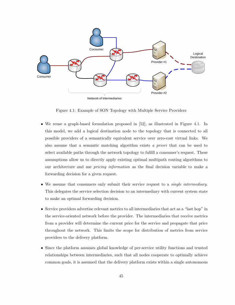
Consumer
Network of Intermediaries
LogicalDestination
Provider #1
Provider #2
Consumer
Figure 4.1: Example of SON Topology with Multiple Service Providers
• We reuse a graph-based formulation proposed in [52], as illustrated in Figure 4.1. In
this model, we add a logical destination node to the topology that is connected to all
possible providers of a semantically equivalent service over zero-cost virtual links. We
also assume that a semantic matching algorithm exists a priori that can be used to
select available paths through the network topology to fulfill a consumer’s request. These
assumptions allow us to directly apply existing optimal multipath routing algorithms to
our architecture and use pricing information as the final decision variable to make a
forwarding decision for a given request.
• We assume that consumers only submit their service request to a single intermediary.
This delegates the service selection decision to an intermediary with current system state
to make an optimal forwarding decision.
• Service providers advertise relevant metrics to all intermediaries that act as a “last hop” in
the service-oriented network before the provider. The intermediaries that receive metrics
from a provider will determine the current price for the service and propagate that price
throughout the network. This limits the scope for distribution of metrics from service
providers to the delivery platform.
• Since the platform assumes global knowledge of per-service utility functions and trusted
relationships between intermediaries, such that all nodes cooperate to optimally achieve
common goals, it is assumed that the delivery platform exists within a single autonomous
45
system.
4.2.3 Methodologies Integrated in the Platform
The service delivery platform is based on the integration of several key methodologies:
content-based routing, optimal routing and flow control theory, network economics, and con-
gestion pricing. In the subsections below, we give a brief overview of relevant issues related to
each the methodologies in our service delivery platform.
Content-Based Routing
While previously discouraged because it violates the networking end-to-end principle,
the idea of using network intermediaries to provide value-added application-aware function in
the network fabric has recently been embraced [53]. Similar to active and overlay networks in
its objective, service-oriented networking challenges the previous assumption that implementing
application-awareness in the network fabric is too costly and complex [51]. Due to advances in
hardware, software, and networking technologies, intermediaries are able to understand data
encoded in XML and legacy formats, act upon that content to enforce QoS or security poli-
cies, transform the data into an alternate representation, and/or make content-based routing
decisions.
We directly leverage the content-based routing function provided by a service-oriented
network to enable request forwarding in our service delivery platform. Content-based routing
algorithms typically apply rules against some portion of a service request (header or content)
to extract attributes. These attributes are used to semantically match the service request to
possible providers in the service-oriented network topology.
In conventional network layer routers and switches, the amount of resources per packet
is approximately constant; this greatly simplifies capacity planning and network design. How-
ever, we argue that the resources required per request in application-layer devices is not con-
stant, and furthermore, that building accurate characterizations of application-layer workload
is a difficult and possibly intractable problem. Instead of trying to develop such a model, we
believe that a measurement-driven, autonomic approach to resource allocation based on metrics
such as CPU or memory utilization is a more elegant and feasible solution. This logic can also
be applied to resource allocation problems of service providers, as done in [54], to define the
effective capacity of a resource, as defined as cj in the formulation shown in Section 4.3.
46
Optimal Routing & Flow Control
In addition to considering the content of requests, our service delivery platform also
incorporates the observed state of the system into its optimal routing algorithm. In the seminal
paper [55], a distributed algorithm to an optimal minimum delay routing problem is presented.
The algorithm populates routing tables with weights that represent the fraction of incoming
traffic that should be forwarded to the neighboring nodes in the network. The solution reveals
that these weights are a function of the measured marginal delay on the link to each neighbor.
An extension of this work is presented in [56], where the restrictions in [55] of quasi-stationary
traffic, synchronization of nodes, and knowledge of the aggregate traffic demand at each node are
removed. It is also shown how a near-optimal multipath routing algorithm can be implemented
in a distance-vector framework while maintaining loop-free routes at every instant.
In addition to using optimal routing, we must ensure that the rate of incoming re-
quests to a particular node in our service delivery platform is throttled appropriately. We can
achieve this by integrating optimal flow control into our architecture. A proposed method for
integrating a utility-maximization problem and optimal flow control is presented in [57], where
the optimal routing and flow control problems are solved simultaneously while observing capac-
ity constraints. The issue of fairness in such an algorithm is addressed in [58]. By definition,
a strictly utility-based algorithm will converge to a Pareto-optimal equilibrium, which is log-
ically equivalent to the concept of max-min fairness. However, we believe that a flow control
mechanism that implements per-service-weighted proportional fairness is more appropriate for
our platform.
The integration of a distributed, loop-free, and optimal multipath routing and flow
control algorithm is essential to the robustness and scalability of our service delivery platform.
Since forwarding costs are determined by the sum of the congestion price of the intermediary in
question and the price as advertised by the next hop (an intermediary or a provider), we exploit
the additive path cost property of the underlying economic framework to build the requisite
service routing protocol.
Network Economics
Microeconomics offers a well-developed theory on the subject of rational choice in
multi-agent environments; utility functions and price are natural ways to express the common
tradeoffs in such systems. Microeconomic models have been extensively applied to various engi-
47
neering problems; for example, network economics are used in [52] as a method to solve dynamic
supply chain management problems. The solutions that are yielded from these methods have
many desirable properties, for example, provable convergence to a Pareto-optimal equilibrium,
in which no other solution exists that could increase the benefit of a user without reducing the
benefit of another user. A comprehensive review of how economic theory can be applied to
various networking problems is found in [59].
In our architecture, we incorporate the economic concept of social welfare maximiza-
tion when formulating our optimization problem for the platform, as seen in (4.1) in Section
4.3. A key distinction of our work, as compared to prior attempts in the literature, is that
our formulation does not rely on the perceived or advertised utility from consumers; rather, we
explicitly link the utility of services to the benefit that a corporation derives from providing
the IT infrastructure. The benefits of this distinction are two-fold; first, it allows us to avoid
restrictive assumptions about the explicit knowledge and/or validity of the utility functions for
the system. Second, it delivers a link between IT resources and the benefits that are derived
from them, which is the premise for adopting SOAs.
Congestion Pricing
The law of supply and demand states that as the available quantity of a resource
decreases, the unit price should increase to reflect the scarcity of the resource. Congestion is
defined in economics as a negative market externality, which occurs when a participant in a
market can make a decision that adversely affects other participants in the market without
penalty. By integrating the current level of congestion observed into the total price paid to
obtain a service, we “internalize the externality” and successfully manage the tradeoff between
idle resources and degradation of service [59].
Congestion pricing was first proposed in [60] as a basis for welfare economics and has
been subsequently been applied to many engineering disciplines [61, 62]. The use of congestion-
pricing resources has been investigated extensively in the networking literature in an attempt to
address resource allocation problems [63]. We apply the concept of congestion pricing to balance
the current state of the underlying network conditions and the performance characteristics of
service providers and network intermediaries in order to optimally route requests [59]. This is
represented by the term f(xs, γf , zf ) in (4.1), shown in Section 4.3.
The notion of “split-edge” pricing was proposed in [64]. In this model, prices are
determined locally and solely reflect prices from onward networks and providers in providing the
48
service; however, pricing information is consolidated at each step, whether it be an intermediate
broker or the actual provider. Split-edge pricing is analogous to additive path cost in next-hop
routing algorithms, such as a distributed Bellman-Ford algorithm, where knowledge of the full
topology and paths through the network are not required in order to make minimum cost
routing decisions. We leverage split-edge pricing in the distributed solution to the optimization
problem described in the next section.
We believe that the combination of “split-edge” and congestion pricing provides an
intuitive and scalable method to provide congestion control in our service delivery platform. Our
architecture is flexible in such a way that it is configurable for administrators to set congestion-
based prices for invoking transport services, the services of an intermediary, and the desired
service at a particular provider, or any subset of the prices therein. A description of how to set
a congestion price for networked applications is presented in [65], and a realistic system built
on this premise is proposed in [66].
An inclusive overview of pricing schemes for networks is provided in [67]. However,
the majority of the work in this area is theoretical in nature, and does not discuss issues with
practical implementations of such systems.
4.2.4 Related Work in Service Systems
There are several previous attempts that have been made towards developing brokered
architectures that connect service consumers to service providers. Several proposals have been
made to create “service overlay networks” with the intent of applying advances in overlay net-
work research to the services layer. In [68], an open service market architecture is presented that
aims to balance load across multiple service providers by using a network of proxies configured
by an external centralized “trader” that computes the optimal routes for service requests. This
architecture does not consider the current state of the proxies when making routing decisions.
The authors of [69] propose a management overlay for Web Services based on interconnected
service intermediaries, but do not address the service selection or routing problems.
Several previous efforts have focused on using overlay methodologies to provide better
end-to-end quality of service for requests in the network by provisioning bandwidth or selecting
the best path through the network based on available bandwidth [70, 71, 72]. The integration of
bandwidth and other QoS metrics into optimizations in a service overlay network is presented
in [73]. There have also been attempts to develop a service overlay network based upon network
economics [74]. While the overarching goals of the work in this area are similar to ours, the work
49
assumes that nodes of the service overlay network are inherently selfish and non-cooperative;
this distinction has a dramatic effect on the underlying economic framework they create, thus
making their work inapplicable to the problems we address. A utility-based framework for
admission control is presented in [75] that uses an estimate of the service time for each request
in determining its value in the larger system. A useful review of brokered service-oriented
systems is shown in [76].
Service selection algorithms utilize rational decision making processes that are used
to decide which service instance to invoke according to some predefined criteria. A common
component of such algorithms is the concept of a QoS registry [77]. A multi-agent approach to
distributed service selection is proposed in [78]; however, the underlying transportation costs
of the network are not considered in the model. A network-sensitive service selection algorithm
is proposed in [79], but it does not incorporate the current state of the service providers or the
intermediaries in the selection decision.
The concepts of brokered architectures and service selection are also addressed in the
supply chain management literature. There is an increasing amount of literature discussing
the application of multi-agent systems to dynamic supply chain management problems [80].
Transportation and handling costs in a graph-theoretic framework are integrated with tradi-
tional supply chain analysis in [52] and the references therein. A combined service selection and
service pricing framework for supply chain managers is discussed in [81]. Distributed pricing
issues in supply chains are addressed in [82].
4.3 Analytic Framework of Service Delivery Platform
The analytic foundation for our service delivery platform comes from the merger of
the key methodologies described in the previous section and the concept of network utility max-
imization (NUM) [83]. In this section, we reuse the notation and closely follow the derivation
as presented in [84, 85].
Consider a service-oriented network with resources that consist of intermediaries and
providers, denoted by J = 1, 2, . . . , J . Let cj be the capacity of resource j ∈ J and c =
[c1, c2, . . . , cJ ]T. Let S = 1, 2, . . . , S be the set of sources (consumers). Each source s has Ks
available loop-free paths from the source to the logical destination node corresponding to the
semantic service that is being consumed by a source. Let Hs be a J ×Ks 0 − 1 matrix that
50

describes the mapping of resources on paths for particular sources; that is,
Hsji =
1, if path i of source s uses resource j
0, otherwise
Let Hs be the set of all columns of Hs that represent all available paths to source s under
single-path routing. Define the J ×K matrix H as
H =[H1, H2, . . . ,HS
]where K :=
∑sK
s. H defines the topology of the service-oriented network.
Let ws be a Ks × 1 vector where the ith entry represents the fraction of s’s flow on
its ith path such that
wsi ≥ 0 ∀i, and 1Tws = 1
where 1 is a vector of an appropriate dimension with the value 1 in every entry. We allow
wsi ∈ [0, 1] for multipath routing. Collect the vectors ws, s = 1, . . . , S into a K × S block
diagonal matrix W . Let W be the set of all such matrices corresponding to multipath routing
as
W ={W |W = diag
(w1, . . . , wS
)∈ [0, 1]K×S ,1Tws = 1
}As mentioned above, H defines the set of loop-free paths available to each source,
and also represents the network topology. W defines how the sources split the load across the
multiple paths. Their product defines a J × S routing matrix R = HW that specifies the
fraction of s’s flow at each resource j. The set of all multipath routing matrices is:
R = {R |R = HW,W ∈ W}
A multipath routing matrix in R is one with entries in the range [0, 1]:
Rjs =
> 0, if resource j is in a path of source s
= 0, otherwise.
The path of source s is denoted by rs = [R1s, . . . , RJs]T, the sth column of the routing matrix
R.
We wish to consider the following optimization problem:
maxR∈R
maxx≥0
∑s∈S
Us(xs)−∑f∈Fs
f(xs, γf , zf )
(4.1)
s.t. Rx ≤ c (4.2)
51

(4.1) optimizes “social welfare” by maximizing utility over both source rates and routes. How-
ever, (4.1) is not a convex problem because the feasible set specified by Rx ≤ c is generally not
convex since it is the product of two variables R and x.
We now transform the problem by defining the Ks×1 vectors ys in terms of the scalar
xs, and the Ks × 1 vectors ws as the new variables:
ys = xsws (4.3)
The mapping from (xs, ws) to ys is one-to-one; the inverse of (4.3) is xs = 1Tys and ws = ys/xs.
Now we change the variables in (4.1) and (4.2) from (W,x) to y, by substituting
xs = 1Tys and Rx = HWx = Hy, obtaining the equivalent problem:
maxy≥0
∑s∈S
Us (1Tys)−∑f∈Fs
f(1Tys, γf , zf )
(4.4)
s.t. Hy ≤ c. (4.5)
Provided the functions Us(·) and f(·) are strictly concave, this is a strictly concave problem
with a linear constraint, and therefore has no duality gap [86].
4.3.1 Distributed Algorithm
To find a distributed algorithm that solves (4.4) & (4.5), we inspect the problem
through its Lagrangian dual. We form the following Lagrangian:
L(y, p) =∑s∈S
Us (1Tys)−∑f∈Fs
f(1Tys, γf , zf )
(4.6)
−J∑j=1
pj(Hy − c) (4.7)
where p =[p1, p2, . . . , pJ
]T is a J×1 vector of Lagrange multipliers associated with the capacity
constraint on resource j. Letting psi =∑J
j=1Hsjip
j and ps = [ps1, . . . , psKs ]. We continue by
formulating the objective function of the dual problem as:
D(p)= maxy≥0
L(y, p) (4.8)
= maxy≥0
∑s∈S
Us (1Tys)−∑f∈Fs
f(1Tys, γf , zf )
(4.9)
−∑s∈S
psys +
J∑j=1
pjc (4.10)
52

We let Bs(ys, ps) be defined as:
Bs(ys, ps) = maxy≥0
Us (1Tys) ∑f∈Fs
f(1Tys, γf , zf )− psys
Since D(p) is separable in s, we can swap the order of the maximization and the summation,
forming the following equivalent equation:
D(p) =∑s∈S
Bs(ys, ps) +J∑j=1
pjc (4.11)
The dual problem of (4.4) & (4.5) corresponds to minimizing D over the dual variables
p, i.e.
minp≥0
D(p)
Since the objective function of the primal problem (4.4) & (4.5) is strictly concave, the dual
problem is always differentiable. The gradient of D is:
δD
δpj= cj −
∑s∈S
Ks∑i=1
Hsjiy∗si
where y∗si comes from the solution of Bs(ys, ps).
Using gradient descent iterations on the dual variables yields the following equation:
pj(t+ 1) =
[pj(t) + βj
(cj −
∑s∈S
Ks∑i=1
Hsjiy
si (t)
)]+
(4.12)
where ysi (t) is the solution of the following optimization problem at time t:
ysi (t+ 1) = maxys
i≥0Us(1Tys
)−∑f∈Fs
f(1Tys, γf , zf ) (4.13)
− ysiJ∑j=1
pj(t)Hsji (4.14)
The joint solution of (4.12) - (4.14) completes the distributed algorithm that solves
(4.1). The resources update the rates of each source ysi by based on explicit feedback from
downstream resources via congestion prices pj . Each resource maximizes the utility for source
s while balancing the price of placing load on a path i. The path price is the product of the
source rate with the price per load for path i (computing by summing pj over all resources in
the path). The assignment of the rates ysi at the resources determines the total traffic that
traverses each resource. The resulting load through each resource serves as implicit feedback
that is used to compute the congestion price pj .
53
Convergence of Gradient Descent Algorithm
Convergence of this algorithm is presented in [84, 87, 88], as it is classified as a sepa-
rable, strictly concave nonlinear optimization problem with linear constraints; the convergence
of a gradient projection algorithm applied to such a problem is well-known for sufficiently small
step sizes βj > 0.
4.4 Engineering Tradeoffs in the Service Delivery Platform
Selecting appropriate utility and cost functions for services is critical to allocating
resources of the service delivery platform in a manner that is congruent to the over-arching
goals of an enterprise. It may be desirable for the overall allocation of resources to be, in some
sense, “fair”, while in other instantiations, the allocation provided by a strict maximization of
social welfare may be sufficient. It might also be desirable to assign utility or cost functions
to services that are not concave, continuous, or both; for example, if there is no utility to the
providing any rate allocation for a service that is less than α requests per second, a discontinuous
utility function would be needed. In this section, we further discuss the issues of fairness of rate
allocations and the impact of selecting nonconcave or discontinous functions on the underlying
analytic framework of our service delivery platform.
4.4.1 Fairness versus Efficiency
As in traditional welfare economic theory, a tradeoff exists between the overall effi-
ciency of the service delivery platform and the distribution of allocated rates amongst services.
The optimal solution to (4.4) & (4.5) will be an allocation of service request rates to available
paths through the service-oriented network such that the overall utility obtained from the al-
location is maximized. However, the allocation of rates to services may be unfair; that is, it
may strongly favor some services thus providing little or no allocation to others. By selecting
particular classes of utility functions for all services, certain measures of fairness can be ensured
in the allocation, such as max-min and proportional fairness, as well as weighted measures of
both.
Max-min fairness, as defined in [89], states that a rate for a particular service s can
not be increased without decreasing a rate for any other service that is currently receiving the
same or a lesser allocation than s. It is shown in [57] that a solution to a utility maximization
54
problem with the following utility functions, as α→∞ will be fair in a max-min sense:
Uα(x) = −(− log x)α
Proportional fairness was first defined in [57] for an allocation of flows in a utility-
based algorithm. A rate allocation xs is considered to be proportionally fair for ωs = 1 if for
all other feasible allocations x′s there does not exist an allocation that can increase the sum of
the proportional rate changes: ∑s∈S
ωsx′s − xsxs
≤ 0
A proportionally fair allocation can be obtained in the service delivery platform by using log xs
as the utility function for all services.
Weighted versions of max-min and proportional fairness have also been defined in the
literature for this type of problem [90, 59]. Weighted proportional fairness can be achieved by
varying the value of ωs on a per-service basis using the utility function ωs log xs.
Since the efficiency and fairness of the service delivery platform are often competing
objectives, it is the responsibility of the system administrator to choose a fairness scheme if one
is desired. There is a complex relationship between the capacity of resources and the overall
fairness and efficiency of the allocations in the service delivery platform that is directly affected
by the choice of utility function. It has been shown in [91] that if all sources have the same
utility function and if the capacity of a single resource is increased, the overall throughput of
the system can actually be decreased; this is a direct consequence of Braess’s paradox.
4.4.2 Concavity versus Nonconcavity
To this point, our architecture and subsequent formulation have only considered ser-
vices with concave utility functions, more generally referred to in the literature as elastic ser-
vices. The assumption of concave utility functions is directly related to the economic law of
diminishing returns, stating that as the number of service requests increases, the marginal
utility obtained from servicing these additional requests decreases.
In [92], Shenker argued that network designs should also consider inelastic services
that have real-time or hard requirements for bandwidth. Inelastic services usually have utility
functions that are discontinuous or nonconcave in shape as a function of the rate they receive. It
may be desirable to associate a utility function that has a nonconcave or discontinuous form, as
seen in Figure 4.2, with a particular service or services. This assignment can have a significant
effect on the solution method, which we discuss in detail in this section.
55
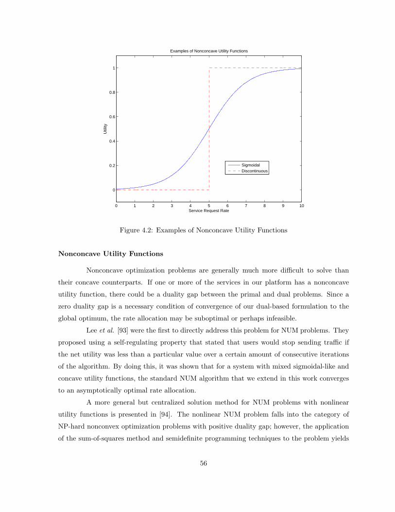
0 1 2 3 4 5 6 7 8 9 10
0
0.2
0.4
0.6
0.8
1
Service Request Rate
Util
ity
Examples of Nonconcave Utility Functions
SigmoidalDiscontinuous
Figure 4.2: Examples of Nonconcave Utility Functions
Nonconcave Utility Functions
Nonconcave optimization problems are generally much more difficult to solve than
their concave counterparts. If one or more of the services in our platform has a nonconcave
utility function, there could be a duality gap between the primal and dual problems. Since a
zero duality gap is a necessary condition of convergence of our dual-based formulation to the
global optimum, the rate allocation may be suboptimal or perhaps infeasible.
Lee et al. [93] were the first to directly address this problem for NUM problems. They
proposed using a self-regulating property that stated that users would stop sending traffic if
the net utility was less than a particular value over a certain amount of consecutive iterations
of the algorithm. By doing this, it was shown that for a system with mixed sigmoidal-like and
concave utility functions, the standard NUM algorithm that we extend in this work converges
to an asymptotically optimal rate allocation.
A more general but centralized solution method for NUM problems with nonlinear
utility functions is presented in [94]. The nonlinear NUM problem falls into the category of
NP-hard nonconvex optimization problems with positive duality gap; however, the application
of the sum-of-squares method and semidefinite programming techniques to the problem yields
56
the optimal solution in polynomial time.
The authors of [95] present a new set of necessary and sufficient conditions for con-
vergence of the dual-based distributed NUM algorithm with nonconcave utility functions. It is
argued that a zero duality gap can be achieved by ensuring the concavity of a slightly different
utility function with an argument of the resource capacities, rather than the allocated aggre-
gate rate. Therefore, by appropriately provisioning the capacity of resources, the algorithm is
ensured to converge to the optimal solution with nonconcave utility functions.
Discontinuous Utility Functions
Situations may exist in application-layer service level agreements where strict min-
imums exist for the allocated rate of requests for a particular service to be carried through
the service-oriented network. These types of services can be supported in the service delivery
platform by assigning discontinuous utility functions, such as the step function seen in Figure
4.2, to the services.
The use of a mixture of elastic (concave) and discontinuous utility functions into a
NUM formulation is discussed in [95]. A sub-optimal heuristic is presented that, in conjunction
with admission control, tentatively admits the desired rate for a particular source, provided the
additive path cost is less than a threshold for a subsequent number of time slots before actually
allowing traffic from the source to flow through the network. Another algorithm is presented
to address scenarios where utility functions for sources are a mixture of strictly elastic as well
as discontinous functions that take a concave shape for rates higher than the strict minimum
desired. For this scenario, the authors present an optimal algorithm that allocates a certain
percent of the total capacity to the discontinuous sources while still supporting the completely
elastic sources.
Revisiting Fairness with Nonconcave Utility Functions
As discussed in Section 4.4.1, fairness of a rate allocation can be an important factor
in deploying an instantiation of our service delivery platform. However, the max-min and
proportional fairness measures we presented require the utility functions to be consistent and
concave. While fairness measures for a NUM formulation that incorporates utility functions
of various shapes remain largely undefined, the authors of [58] use a slightly modified single-
path NUM formulation that employs two new fairness concepts: utility max-min and utility
proportional fairness. These concepts directly incorporate the utility derived from a particular
57
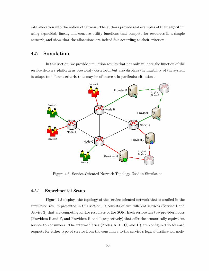
rate allocation into the notion of fairness. The authors provide real examples of their algorithm
using sigmoidal, linear, and concave utility functions that compete for resources in a simple
network, and show that the allocations are indeed fair according to their criterion.
4.5 Simulation
In this section, we provide simulation results that not only validate the function of the
service delivery platform as previously described, but also displays the flexibility of the system
to adapt to different criteria that may be of interest in particular situations.
Logical Node G
LogicalNode K
Service 1
Service 2
Service 2
Provider E
Provider J
Provider F
Provider H
Node D
Node B
Node C
Node A
Service 1
Figure 4.3: Service-Oriented Network Topology Used in Simulation
4.5.1 Experimental Setup
Figure 4.3 displays the topology of the service-oriented network that is studied in the
simulation results presented in this section. It consists of two different services (Service 1 and
Service 2) that are competing for the resources of the SON. Each service has two provider nodes
(Providers E and F, and Providers H and J, respectively) that offer the semantically equivalent
service to consumers. The intermediaries (Nodes A, B, C, and D) are configured to forward
requests for either type of service from the consumers to the service’s logical destination node.
58
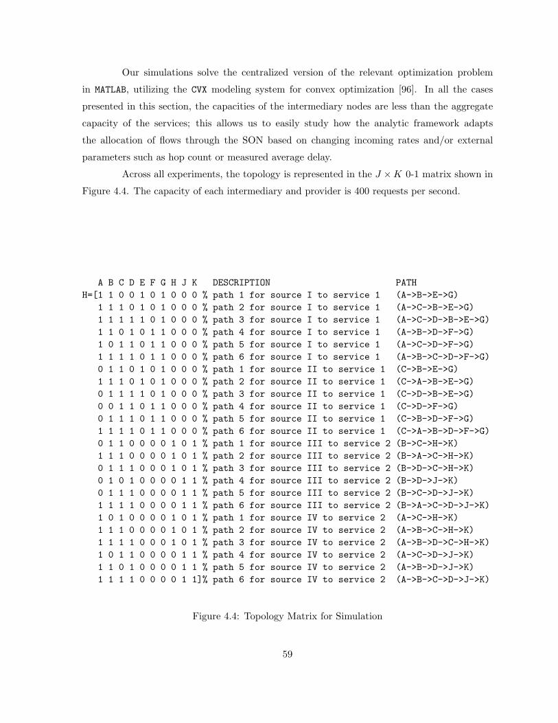
Our simulations solve the centralized version of the relevant optimization problem
in MATLAB, utilizing the CVX modeling system for convex optimization [96]. In all the cases
presented in this section, the capacities of the intermediary nodes are less than the aggregate
capacity of the services; this allows us to easily study how the analytic framework adapts
the allocation of flows through the SON based on changing incoming rates and/or external
parameters such as hop count or measured average delay.
Across all experiments, the topology is represented in the J ×K 0-1 matrix shown in
Figure 4.4. The capacity of each intermediary and provider is 400 requests per second.
A B C D E F G H J K DESCRIPTION PATHH=[1 1 0 0 1 0 1 0 0 0 % path 1 for source I to service 1 (A->B->E->G)
1 1 1 0 1 0 1 0 0 0 % path 2 for source I to service 1 (A->C->B->E->G)1 1 1 1 1 0 1 0 0 0 % path 3 for source I to service 1 (A->C->D->B->E->G)1 1 0 1 0 1 1 0 0 0 % path 4 for source I to service 1 (A->B->D->F->G)1 0 1 1 0 1 1 0 0 0 % path 5 for source I to service 1 (A->C->D->F->G)1 1 1 1 0 1 1 0 0 0 % path 6 for source I to service 1 (A->B->C->D->F->G)0 1 1 0 1 0 1 0 0 0 % path 1 for source II to service 1 (C->B->E->G)1 1 1 0 1 0 1 0 0 0 % path 2 for source II to service 1 (C->A->B->E->G)0 1 1 1 1 0 1 0 0 0 % path 3 for source II to service 1 (C->D->B->E->G)0 0 1 1 0 1 1 0 0 0 % path 4 for source II to service 1 (C->D->F->G)0 1 1 1 0 1 1 0 0 0 % path 5 for source II to service 1 (C->B->D->F->G)1 1 1 1 0 1 1 0 0 0 % path 6 for source II to service 1 (C->A->B->D->F->G)0 1 1 0 0 0 0 1 0 1 % path 1 for source III to service 2 (B->C->H->K)1 1 1 0 0 0 0 1 0 1 % path 2 for source III to service 2 (B->A->C->H->K)0 1 1 1 0 0 0 1 0 1 % path 3 for source III to service 2 (B->D->C->H->K)0 1 0 1 0 0 0 0 1 1 % path 4 for source III to service 2 (B->D->J->K)0 1 1 1 0 0 0 0 1 1 % path 5 for source III to service 2 (B->C->D->J->K)1 1 1 1 0 0 0 0 1 1 % path 6 for source III to service 2 (B->A->C->D->J->K)1 0 1 0 0 0 0 1 0 1 % path 1 for source IV to service 2 (A->C->H->K)1 1 1 0 0 0 0 1 0 1 % path 2 for source IV to service 2 (A->B->C->H->K)1 1 1 1 0 0 0 1 0 1 % path 3 for source IV to service 2 (A->B->D->C->H->K)1 0 1 1 0 0 0 0 1 1 % path 4 for source IV to service 2 (A->C->D->J->K)1 1 0 1 0 0 0 0 1 1 % path 5 for source IV to service 2 (A->B->D->J->K)1 1 1 1 0 0 0 0 1 1]% path 6 for source IV to service 2 (A->B->C->D->J->K)
Figure 4.4: Topology Matrix for Simulation
59
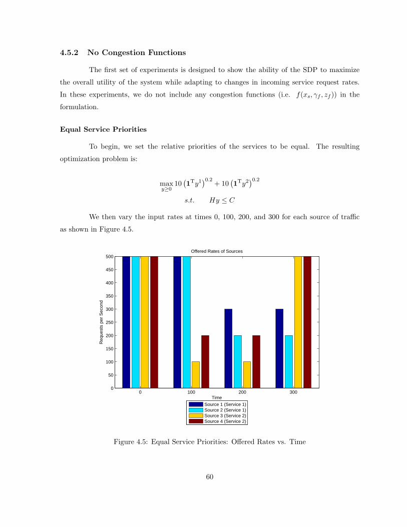
4.5.2 No Congestion Functions
The first set of experiments is designed to show the ability of the SDP to maximize
the overall utility of the system while adapting to changes in incoming service request rates.
In these experiments, we do not include any congestion functions (i.e. f(xs, γf , zf )) in the
formulation.
Equal Service Priorities
To begin, we set the relative priorities of the services to be equal. The resulting
optimization problem is:
maxy≥0
10(1Ty1
)0.2+ 10
(1Ty2
)0.2s.t. Hy ≤ C
We then vary the input rates at times 0, 100, 200, and 300 for each source of traffic
as shown in Figure 4.5.
0 100 200 3000
50
100
150
200
250
300
350
400
450
500Offered Rates of Sources
Req
uest
s pe
r S
econ
d
Time
Source 1 (Service 1)Source 2 (Service 1)Source 3 (Service 2)Source 4 (Service 2)
Figure 4.5: Equal Service Priorities: Offered Rates vs. Time
60
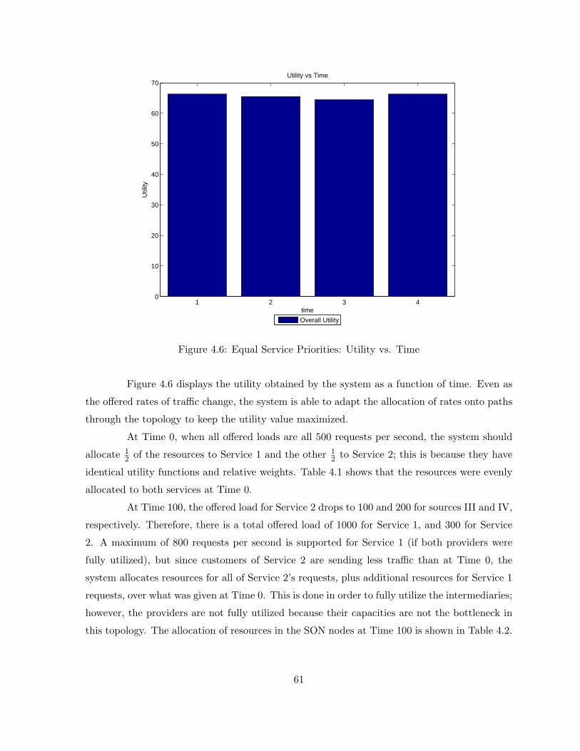
1 2 3 40
10
20
30
40
50
60
70
time
Util
ity
Utility vs Time
Overall Utility
Figure 4.6: Equal Service Priorities: Utility vs. Time
Figure 4.6 displays the utility obtained by the system as a function of time. Even as
the offered rates of traffic change, the system is able to adapt the allocation of rates onto paths
through the topology to keep the utility value maximized.
At Time 0, when all offered loads are all 500 requests per second, the system should
allocate 12 of the resources to Service 1 and the other 1
2 to Service 2; this is because they have
identical utility functions and relative weights. Table 4.1 shows that the resources were evenly
allocated to both services at Time 0.
At Time 100, the offered load for Service 2 drops to 100 and 200 for sources III and IV,
respectively. Therefore, there is a total offered load of 1000 for Service 1, and 300 for Service
2. A maximum of 800 requests per second is supported for Service 1 (if both providers were
fully utilized), but since customers of Service 2 are sending less traffic than at Time 0, the
system allocates resources for all of Service 2’s requests, plus additional resources for Service 1
requests, over what was given at Time 0. This is done in order to fully utilize the intermediaries;
however, the providers are not fully utilized because their capacities are not the bottleneck in
this topology. The allocation of resources in the SON nodes at Time 100 is shown in Table 4.2.
61

Table 4.1: Equal Service Priorities: Node Throughput at Time 0
Service 1 Service 2 Total
Node A 200 200 400
Node B 200 200 400
Node C 200 200 400
Node D 200 200 400
Provider E 200 0 200
Provider F 200 0 200
Provider H 0 200 200
Provider J 0 200 200
At Time 200, the offered load for Service 2 stays at 100 and 200 for sources III and IV,
respectively, but Service 1s offered load drops to 300 and 200 for sources I and II, respectively.
Therefore, Node A is a bottleneck since it is receiving 300 (Service 1) + 200 (Service 2) requests
per second, but only has capacity for 400 requests per second. In this case, the system allocates
over a greater number of paths in order to more fully utilize the resources. The allocation of
resources in the SON nodes at Time 200 is shown in Table 4.3.
At Time 300, the offered load for Service 2 increases to 500 and 500 for sources III
and IV, respectively, but Service 1s offered load remains at 300 and 200 for sources I and II,
respectively. Node A is again a bottleneck since it receives 300 requests per second of Service
1 requests, and 500 requests per second of Service 2 requests. Its capacity is 400 requests per
Table 4.2: Equal Service Priorities: Node Throughput at Time 100
Service 1 Service 2 Total
Node A 200 200 400
Node B 233.3333 166.6667 400
Node C 266.6667 133.3333 400
Node D 233.3333 166.6667 400
Provider E 233.3333 0 233.3333
Provider F 233.3333 0 233.3333
Provider H 0 133.3333 133.3333
Provider J 0 166.6667 166.6667
62

Table 4.3: Equal Service Priorities: Node Throughput at Time 200
Service 1 Service 2 Total
Node A 200 200 400
Node B 221.7769 168.4285 390.2054
Node C 222.5726 170.3124 392.8850
Node D 216.6050 165.1206 381.7257
Provider E 195.6865 0 195.6865
Provider F 204.3135 0 204.3135
Provider H 0 146.1008 146.1008
Provider J 0 153.8992 153.8992
second, so it must drop 400 requests per second. Since both services have the same priority,
Node A evenly drops requests from both types of traffic, resulting in both services receiving
the same capacity; therefore, the results that are shown in Table 4.4 are subsequently similar
to those seen at Time 0 in Table 4.1.
Figures 4.7 and 4.8 display the allocation of Service 1 and Service 2 traffic onto different
paths through the SON as a function of time. In order to reduce contention, the solution to the
optimization problem tends to allocate resources on shorter paths. However, if the incoming
load is unbalanced, the system will allocate resources on multiple paths (that may not be the
shortest) in order to maximize the overall utility of the system; this behavior is visible in Figures
4.7 and 4.8.
Table 4.4: Equal Service Priorities: Node Throughput at Time 300
Service 1 Service 2 Total
Node A 199.9858 200.0142 400
Node B 199.9858 200.0142 400
Node C 199.9858 200.0142 400
Node D 199.9858 200.0142 400
Provider E 199.9858 0 199.9858
Provider F 199.9858 0 199.9858
Provider H 0 200.0142 400
Provider J 0 200.0142 400
63
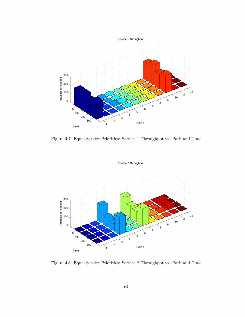
12
34
56
78
910
1112
0100
200300
0
100
200
300
Path #
Service 1 Throughput
Time
Req
uest
s pe
r se
cond
Figure 4.7: Equal Service Priorities: Service 1 Throughput vs. Path and Time
12
34
56
78
910
1112
0100
200300
0
100
200
300
Path #
Service 2 Throughput
Time
Req
uest
s pe
r se
cond
Figure 4.8: Equal Service Priorities: Service 2 Throughput vs. Path and Time
64
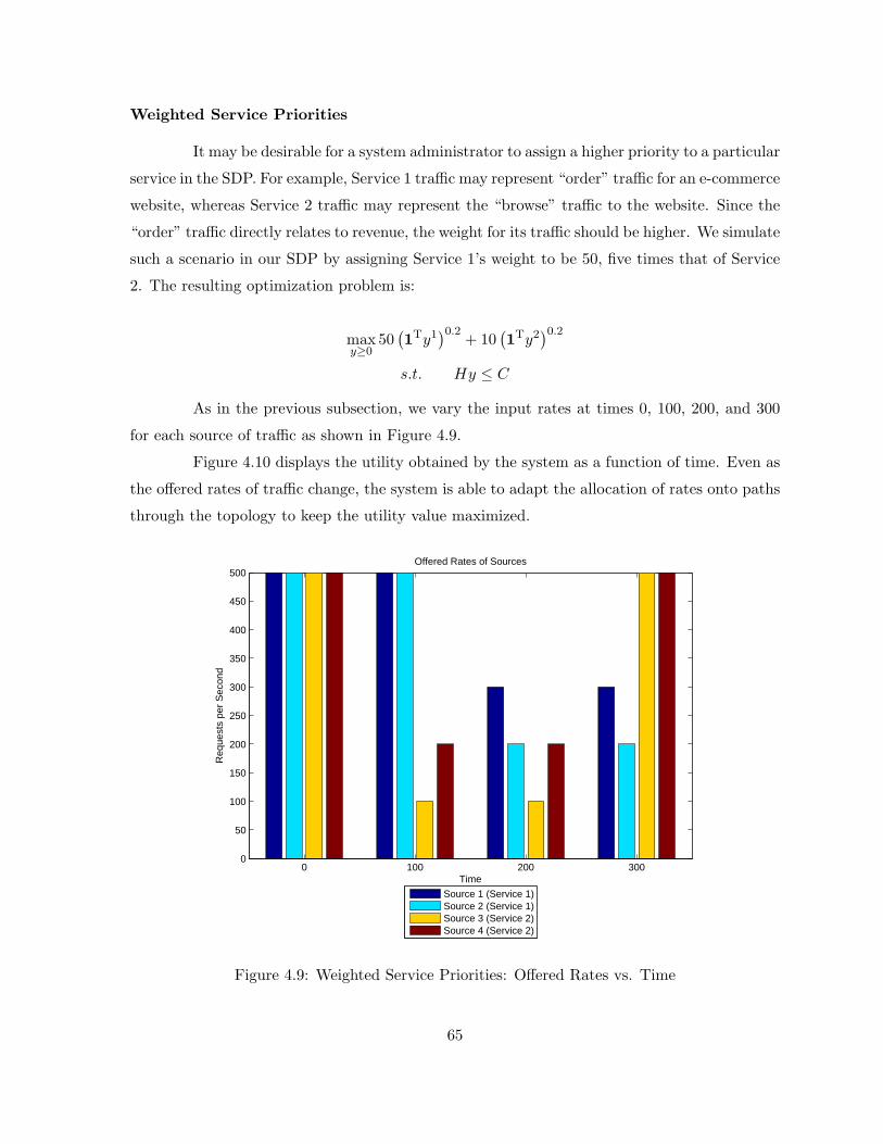
Weighted Service Priorities
It may be desirable for a system administrator to assign a higher priority to a particular
service in the SDP. For example, Service 1 traffic may represent “order” traffic for an e-commerce
website, whereas Service 2 traffic may represent the “browse” traffic to the website. Since the
“order” traffic directly relates to revenue, the weight for its traffic should be higher. We simulate
such a scenario in our SDP by assigning Service 1’s weight to be 50, five times that of Service
2. The resulting optimization problem is:
maxy≥0
50(1Ty1
)0.2+ 10
(1Ty2
)0.2s.t. Hy ≤ C
As in the previous subsection, we vary the input rates at times 0, 100, 200, and 300
for each source of traffic as shown in Figure 4.9.
Figure 4.10 displays the utility obtained by the system as a function of time. Even as
the offered rates of traffic change, the system is able to adapt the allocation of rates onto paths
through the topology to keep the utility value maximized.
0 100 200 3000
50
100
150
200
250
300
350
400
450
500Offered Rates of Sources
Req
uest
s pe
r S
econ
d
Time
Source 1 (Service 1)Source 2 (Service 1)Source 3 (Service 2)Source 4 (Service 2)
Figure 4.9: Weighted Service Priorities: Offered Rates vs. Time
65
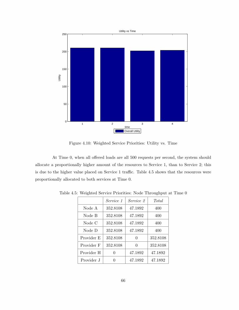
1 2 3 40
50
100
150
200
250
time
Util
ity
Utility vs Time
Overall Utility
Figure 4.10: Weighted Service Priorities: Utility vs. Time
At Time 0, when all offered loads are all 500 requests per second, the system should
allocate a proportionally higher amount of the resources to Service 1, than to Service 2; this
is due to the higher value placed on Service 1 traffic. Table 4.5 shows that the resources were
proportionally allocated to both services at Time 0.
Table 4.5: Weighted Service Priorities: Node Throughput at Time 0
Service 1 Service 2 Total
Node A 352.8108 47.1892 400
Node B 352.8108 47.1892 400
Node C 352.8108 47.1892 400
Node D 352.8108 47.1892 400
Provider E 352.8108 0 352.8108
Provider F 352.8108 0 352.8108
Provider H 0 47.1892 47.1892
Provider J 0 47.1892 47.1892
66

Table 4.6: Weighted Service Priorities: Node Throughput at Time 100
Service 1 Service 2 Total
Node A 352.8108 47.1892 400
Node B 352.8108 47.1892 400
Node C 352.8108 47.1892 400
Node D 352.8108 47.1892 400
Provider E 352.8108 0 352.8108
Provider F 352.8108 0 352.8108
Provider H 0 47.1892 47.1892
Provider J 0 47.1892 47.1892
At Time 100, the offered load for Service 2 drops to 100 and 200 for sources III and
IV, respectively. Therefore, there is a total offered load of 1000 for Service 1 and 300 for Service
2. A maximum of 800 requests per second is supported for Service 1 (if both providers were
fully utilized), but since customers of Service 2 are sending less traffic than at Time 0, the
system allocates the same amount of resources as at Time 0. This is because the proportion
of resources provided to Service 2 is still less that the offered traffic, so we see no change in
allocation. The allocation of resources in the SON nodes at Time 100 is shown in Table 4.6.
At Time 200, the offered load for Service 2 stays at 100 and 200 for sources III and IV,
respectively, but Service 1s offered load drops to 300 and 200 for sources I and II, respectively.
Therefore, Node A is a bottleneck since it is receiving 300 (Service 1) + 200 (Service 2) requests
Table 4.7: Weighted Service Priorities: Node Throughput at Time 200
Service 1 Service 2 Total
Node A 300 100 400
Node B 271.2896 122.6592 393.9488
Node C 269.6065 122.3894 391.9959
Node D 268.2959 115.7557 384.0516
Provider E 243.2970 0 243.2970
Provider F 256.7030 0 256.7030
Provider H 0 96.5774 96.5774
Provider J 0 103.4226 103.4226
67
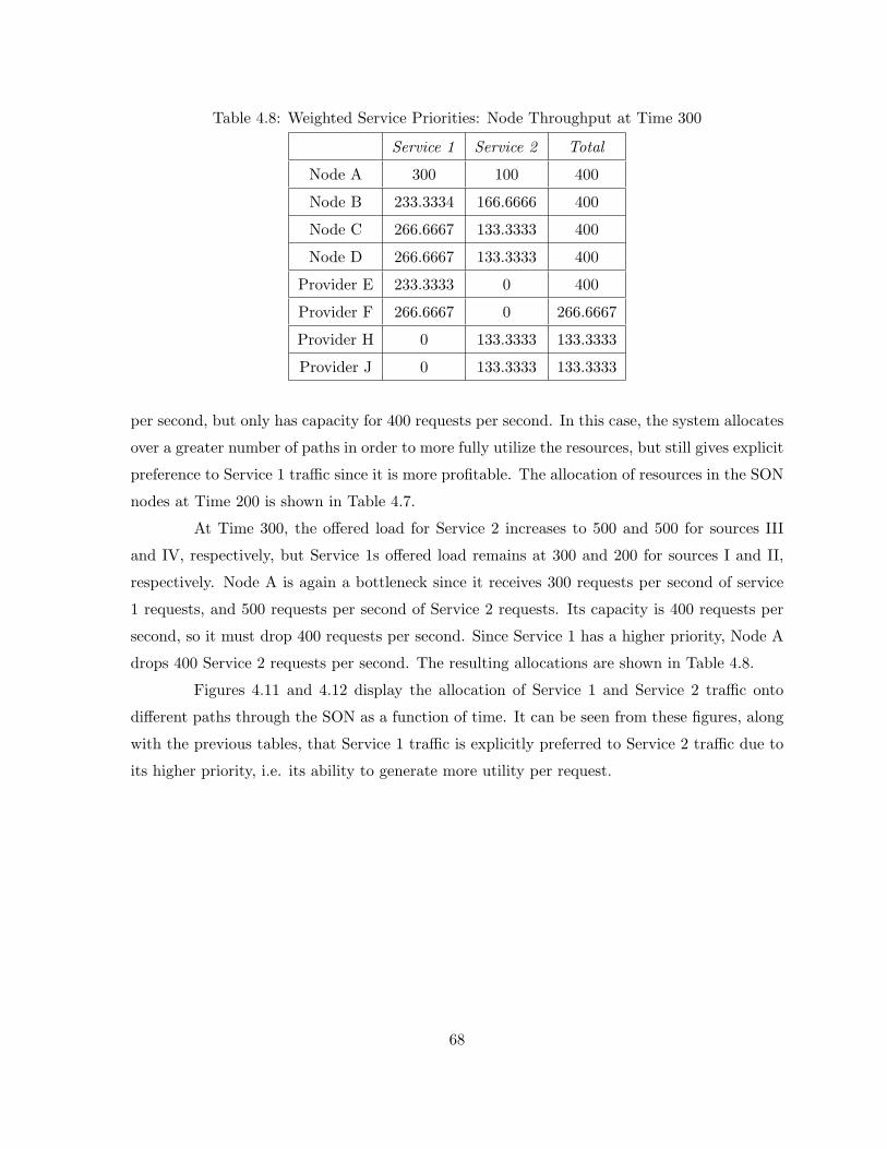
Table 4.8: Weighted Service Priorities: Node Throughput at Time 300
Service 1 Service 2 Total
Node A 300 100 400
Node B 233.3334 166.6666 400
Node C 266.6667 133.3333 400
Node D 266.6667 133.3333 400
Provider E 233.3333 0 400
Provider F 266.6667 0 266.6667
Provider H 0 133.3333 133.3333
Provider J 0 133.3333 133.3333
per second, but only has capacity for 400 requests per second. In this case, the system allocates
over a greater number of paths in order to more fully utilize the resources, but still gives explicit
preference to Service 1 traffic since it is more profitable. The allocation of resources in the SON
nodes at Time 200 is shown in Table 4.7.
At Time 300, the offered load for Service 2 increases to 500 and 500 for sources III
and IV, respectively, but Service 1s offered load remains at 300 and 200 for sources I and II,
respectively. Node A is again a bottleneck since it receives 300 requests per second of service
1 requests, and 500 requests per second of Service 2 requests. Its capacity is 400 requests per
second, so it must drop 400 requests per second. Since Service 1 has a higher priority, Node A
drops 400 Service 2 requests per second. The resulting allocations are shown in Table 4.8.
Figures 4.11 and 4.12 display the allocation of Service 1 and Service 2 traffic onto
different paths through the SON as a function of time. It can be seen from these figures, along
with the previous tables, that Service 1 traffic is explicitly preferred to Service 2 traffic due to
its higher priority, i.e. its ability to generate more utility per request.
68
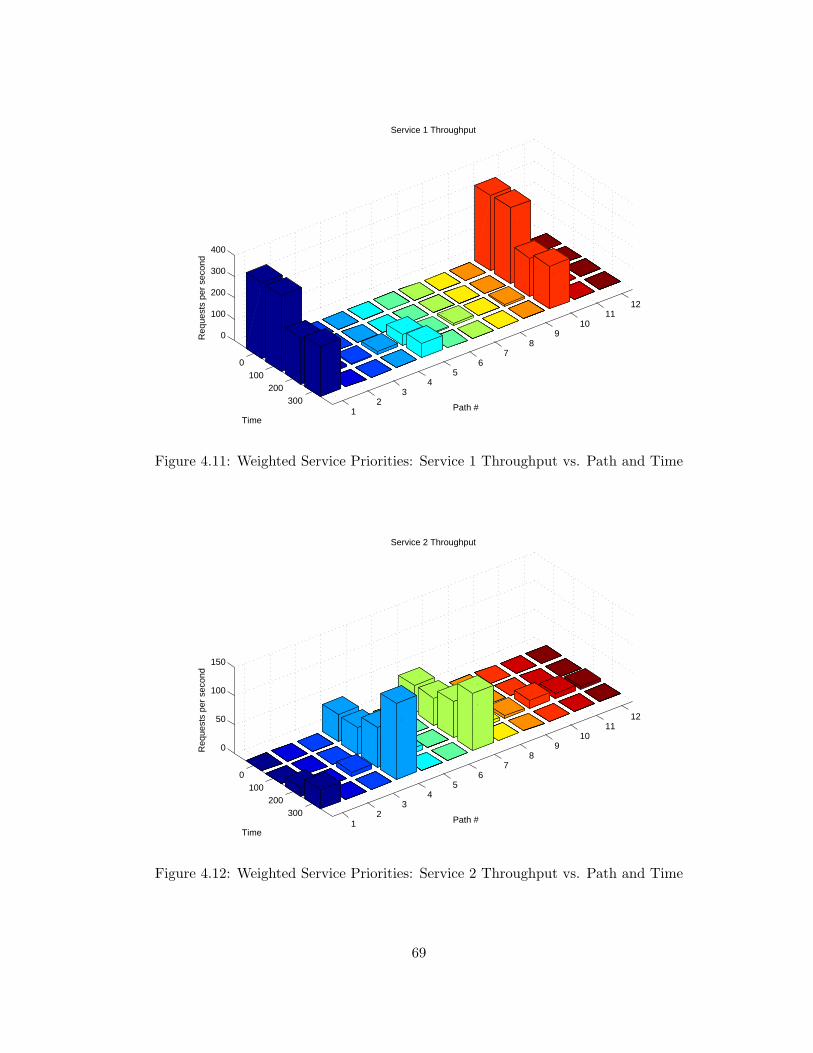
12
34
56
78
910
1112
0100
200300
0
100
200
300
400
Path #
Service 1 Throughput
Time
Req
uest
s pe
r se
cond
Figure 4.11: Weighted Service Priorities: Service 1 Throughput vs. Path and Time
12
34
56
78
910
1112
0100
200300
0
50
100
150
Path #
Service 2 Throughput
Time
Req
uest
s pe
r se
cond
Figure 4.12: Weighted Service Priorities: Service 2 Throughput vs. Path and Time
69
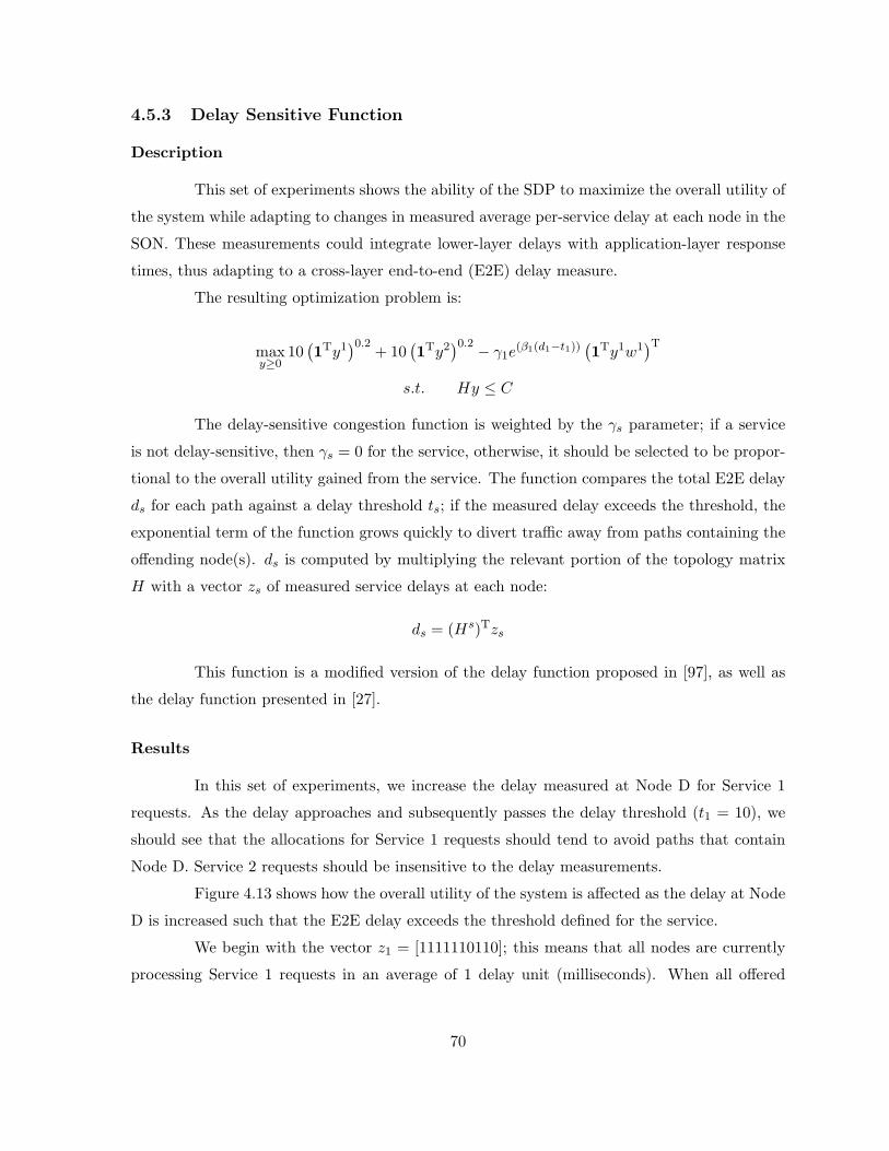
4.5.3 Delay Sensitive Function
Description
This set of experiments shows the ability of the SDP to maximize the overall utility of
the system while adapting to changes in measured average per-service delay at each node in the
SON. These measurements could integrate lower-layer delays with application-layer response
times, thus adapting to a cross-layer end-to-end (E2E) delay measure.
The resulting optimization problem is:
maxy≥0
10(1Ty1
)0.2+ 10
(1Ty2
)0.2 − γ1e(β1(d1−t1))
(1Ty1w1
)Ts.t. Hy ≤ C
The delay-sensitive congestion function is weighted by the γs parameter; if a service
is not delay-sensitive, then γs = 0 for the service, otherwise, it should be selected to be propor-
tional to the overall utility gained from the service. The function compares the total E2E delay
ds for each path against a delay threshold ts; if the measured delay exceeds the threshold, the
exponential term of the function grows quickly to divert traffic away from paths containing the
offending node(s). ds is computed by multiplying the relevant portion of the topology matrix
H with a vector zs of measured service delays at each node:
ds = (Hs)Tzs
This function is a modified version of the delay function proposed in [97], as well as
the delay function presented in [27].
Results
In this set of experiments, we increase the delay measured at Node D for Service 1
requests. As the delay approaches and subsequently passes the delay threshold (t1 = 10), we
should see that the allocations for Service 1 requests should tend to avoid paths that contain
Node D. Service 2 requests should be insensitive to the delay measurements.
Figure 4.13 shows how the overall utility of the system is affected as the delay at Node
D is increased such that the E2E delay exceeds the threshold defined for the service.
We begin with the vector z1 = [1111110110]; this means that all nodes are currently
processing Service 1 requests in an average of 1 delay unit (milliseconds). When all offered
70
1 5 6 7 80
10
20
30
40
50
60
70Utility as a Function of Node D Delay for Service 1
Util
ity
Delay
Figure 4.13: Delay Sensitive Service: Utility vs. Delay
loads are all 500 requests per second, the system should allocate 12 of the resources to Service 1,
and the other 12 to Service 2. This is because they have identical utility functions and relative
weights. Since the delay is uniform across the entire SDP, and it is far below the threshold, it
should have no impact on the allocation, though the overall utility value will be slightly smaller
than the results in Section 4.5.2 at Time 0.
As we continue to increase the delay at Node D for Service 1 traffic, we see in Tables
4.10, 4.11, 4.12, and 4.13 that the system slowly reduces the amount allocated to Service 1 paths
that include Node D until the threshold is met. Then the system explicitly avoids allocating any
traffic to Service 1 paths that include Node D. The system is aware of Service 2’s insensitivity
to delay, so as Service 1 traffic is diverted away from Node D, Service 2 traffic is diverted to
Node D in order to make better use of the available resources. This can be clearly seen in
Figures 4.14 and 4.15, where traffic is routed on to alternate paths in order to maintain the
overall utility of the system.
71
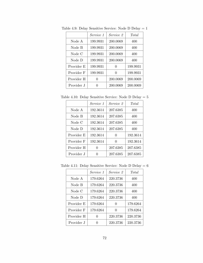
Table 4.9: Delay Sensitive Service: Node D Delay = 1
Service 1 Service 2 Total
Node A 199.9931 200.0069 400
Node B 199.9931 200.0069 400
Node C 199.9931 200.0069 400
Node D 199.9931 200.0069 400
Provider E 199.9931 0 199.9931
Provider F 199.9931 0 199.9931
Provider H 0 200.0069 200.0069
Provider J 0 200.0069 200.0069
Table 4.10: Delay Sensitive Service: Node D Delay = 5
Service 1 Service 2 Total
Node A 192.3614 207.6385 400
Node B 192.3614 207.6385 400
Node C 192.3614 207.6385 400
Node D 192.3614 207.6385 400
Provider E 192.3614 0 192.3614
Provider F 192.3614 0 192.3614
Provider H 0 207.6385 207.6385
Provider J 0 207.6385 207.6385
Table 4.11: Delay Sensitive Service: Node D Delay = 6
Service 1 Service 2 Total
Node A 179.6264 220.3736 400
Node B 179.6264 220.3736 400
Node C 179.6264 220.3736 400
Node D 179.6264 220.3736 400
Provider E 179.6264 0 179.6264
Provider F 179.6264 0 179.6264
Provider H 0 220.3736 220.3736
Provider J 0 220.3736 220.3736
72
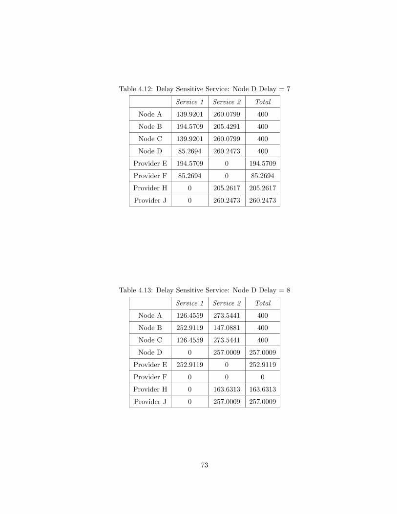
Table 4.12: Delay Sensitive Service: Node D Delay = 7
Service 1 Service 2 Total
Node A 139.9201 260.0799 400
Node B 194.5709 205.4291 400
Node C 139.9201 260.0799 400
Node D 85.2694 260.2473 400
Provider E 194.5709 0 194.5709
Provider F 85.2694 0 85.2694
Provider H 0 205.2617 205.2617
Provider J 0 260.2473 260.2473
Table 4.13: Delay Sensitive Service: Node D Delay = 8
Service 1 Service 2 Total
Node A 126.4559 273.5441 400
Node B 252.9119 147.0881 400
Node C 126.4559 273.5441 400
Node D 0 257.0009 257.0009
Provider E 252.9119 0 252.9119
Provider F 0 0 0
Provider H 0 163.6313 163.6313
Provider J 0 257.0009 257.0009
73
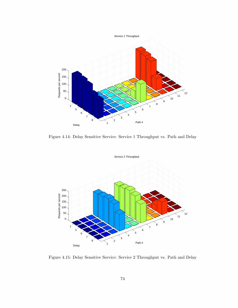
12
34
56
78
910
1112
15
67
8
0
50
100
150
200
Path #
Service 1 Throughput
Delay
Req
uest
s pe
r se
cond
Figure 4.14: Delay Sensitive Service: Service 1 Throughput vs. Path and Delay
12
34
56
78
910
1112
15
67
8
0
50
100
150
200
250
Path #
Service 2 Throughput
Delay
Req
uest
s pe
r se
cond
Figure 4.15: Delay Sensitive Service: Service 2 Throughput vs. Path and Delay
74
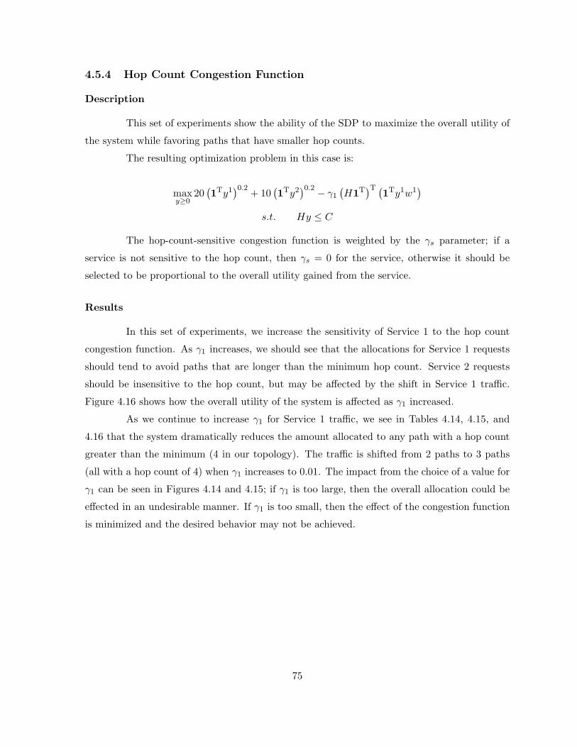
4.5.4 Hop Count Congestion Function
Description
This set of experiments show the ability of the SDP to maximize the overall utility of
the system while favoring paths that have smaller hop counts.
The resulting optimization problem in this case is:
maxy≥0
20(1Ty1
)0.2+ 10
(1Ty2
)0.2 − γ1
(H1T
)T (1Ty1w1
)s.t. Hy ≤ C
The hop-count-sensitive congestion function is weighted by the γs parameter; if a
service is not sensitive to the hop count, then γs = 0 for the service, otherwise it should be
selected to be proportional to the overall utility gained from the service.
Results
In this set of experiments, we increase the sensitivity of Service 1 to the hop count
congestion function. As γ1 increases, we should see that the allocations for Service 1 requests
should tend to avoid paths that are longer than the minimum hop count. Service 2 requests
should be insensitive to the hop count, but may be affected by the shift in Service 1 traffic.
Figure 4.16 shows how the overall utility of the system is affected as γ1 increased.
As we continue to increase γ1 for Service 1 traffic, we see in Tables 4.14, 4.15, and
4.16 that the system dramatically reduces the amount allocated to any path with a hop count
greater than the minimum (4 in our topology). The traffic is shifted from 2 paths to 3 paths
(all with a hop count of 4) when γ1 increases to 0.01. The impact from the choice of a value for
γ1 can be seen in Figures 4.14 and 4.15; if γ1 is too large, then the overall allocation could be
effected in an undesirable manner. If γ1 is too small, then the effect of the congestion function
is minimized and the desired behavior may not be achieved.
75
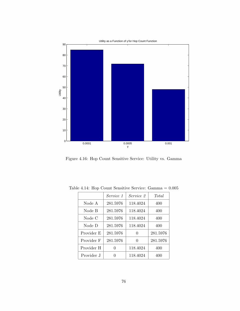
0.0001 0.0005 0.0010
10
20
30
40
50
60
70
80
90Utility as a Function of γ for Hop Count Function
Util
ity
γ
Figure 4.16: Hop Count Sensitive Service: Utility vs. Gamma
Table 4.14: Hop Count Sensitive Service: Gamma = 0.005
Service 1 Service 2 Total
Node A 281.5976 118.4024 400
Node B 281.5976 118.4024 400
Node C 281.5976 118.4024 400
Node D 281.5976 118.4024 400
Provider E 281.5976 0 281.5976
Provider F 281.5976 0 281.5976
Provider H 0 118.4024 400
Provider J 0 118.4024 400
76
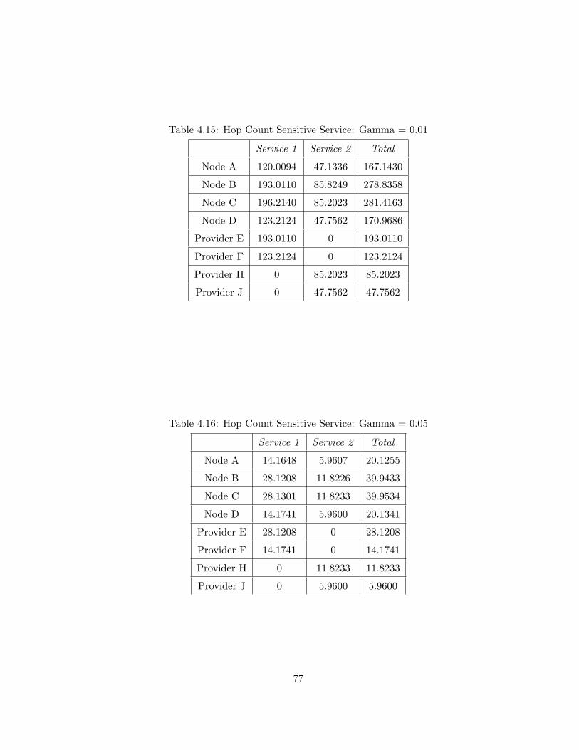
Table 4.15: Hop Count Sensitive Service: Gamma = 0.01
Service 1 Service 2 Total
Node A 120.0094 47.1336 167.1430
Node B 193.0110 85.8249 278.8358
Node C 196.2140 85.2023 281.4163
Node D 123.2124 47.7562 170.9686
Provider E 193.0110 0 193.0110
Provider F 123.2124 0 123.2124
Provider H 0 85.2023 85.2023
Provider J 0 47.7562 47.7562
Table 4.16: Hop Count Sensitive Service: Gamma = 0.05
Service 1 Service 2 Total
Node A 14.1648 5.9607 20.1255
Node B 28.1208 11.8226 39.9433
Node C 28.1301 11.8233 39.9534
Node D 14.1741 5.9600 20.1341
Provider E 28.1208 0 28.1208
Provider F 14.1741 0 14.1741
Provider H 0 11.8233 11.8233
Provider J 0 5.9600 5.9600
77
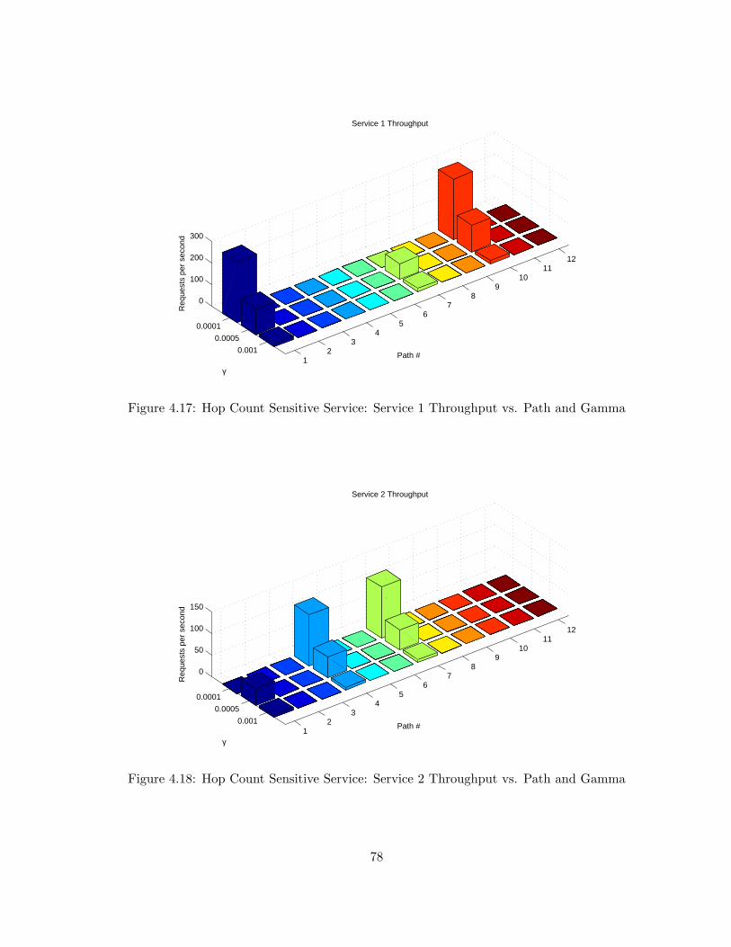
12
34
56
78
910
1112
0.0001
0.0005
0.001
0
100
200
300
Path #
Service 1 Throughput
γ
Req
uest
s pe
r se
cond
Figure 4.17: Hop Count Sensitive Service: Service 1 Throughput vs. Path and Gamma
12
34
56
78
910
1112
0.0001
0.0005
0.001
0
50
100
150
Path #
Service 2 Throughput
γ
Req
uest
s pe
r se
cond
Figure 4.18: Hop Count Sensitive Service: Service 2 Throughput vs. Path and Gamma
78
4.6 Conclusions
In this chapter, we proposed a novel autonomic service delivery platform for service-
oriented network environments. The framework of the platform is based on the methodologies
of content-based routing, network economics, congestion pricing, and optimal routing and flow
control. With a direct link to the business value derived from a service, the service delivery
platform maximizes the value derived from underlying IT resources. We believe that our archi-
tecture provides exciting new multidisciplinary research opportunities in service engineering.
As seen in the results presented in Section 4.5, the choice of the per-service priorities,
as well as the parameter γs that represents the sensitivity of a service to a particular conges-
tion function, has a critical effect on the solution chosen by the service delivery platform. In
order to choose useful values for both of these parameters, the combined use of simulation and
perturbation/sensitivity analysis is suggested.
The combination of the 0-1 matrix H and its presence in the constraint set Hy ≤ C
implies that all requests require the same amount of resources at each node within the SON.
While characterizing application-layer workloads remains an open and relevant research topic
(see Section 5.2.3), the applicability of the system to a realistic setting may be limited unless
this restriction is relaxed. One option is to change the constraint set to H(Ly) ≤ C, where
L is a K × K matrix that converts the units of y from requests to resources. This option
would require the units of C to change from requests to an amount of resources in order to
make the constraint set valid. Since L ∈ (0, 1], the constraint set remains a weighted sum of
linear functions with positive weights, which is known to be convex [87]. The addition of L to
the constraint set allows the service delivery platform to allocate resources based on a linear
relationship between number of requests carried on a path and the amount of resources (CPU,
memory, etc) required to process a single request on all nodes in that path.
Some future issues to address include investigating efficient methods to estimate the
derivatives of the congestion prices f(xs, γf , zf ) in (4.1). Further investigation into issues of
fairness when a mixture of different shapes of utility functions exists in the delivery platform
is needed. It may be desirable to impose per-source or per-path preferences on the overall
allocation of resources. The use of additional congestion functions could be employed to affect
such preferences; for example, f(xs, γf , zf ) = log(psxsws) where ps is a vector of per-path (or
per-source, if the weights are applied across all paths available to a particular source) weights.
Finally, we believe that further investigation into the interactions between autonomous systems
79

could have important effects in business-to-business interactions in such an instantiation of our
distributed service delivery platform.
80
Chapter 5
Conclusions
This dissertation has presented the paradigm of service-oriented networking, discussed
large-scale service-oriented systems, and proposed a new autonomic service delivery platform
for optimal routing and flow control of service requests to multiple service providers in a service-
oriented network. This chapter summarizes and suggests future extensions for our work.
5.1 Summary of this Dissertation
In this dissertation, we formally proposed service-oriented networking as an emerging
middleware and telecommunications architecture. We discussed the challenges, both in building
SON devices, as well as in interconnecting the devices to form a true networked system. We
continued by discussing large-scale service-oriented networks by explicitly describing a use case
for SON, federations of ESBs. We described how federations can be enabled by a distributed
service registry, and provided details and examples of two protocols, based upon Internet rout-
ing protocols, that enable a robust, scalable, and dynamic infrastructure. Finally, we presented
our autonomic service delivery platform. The goal of this platform is to optimally route re-
quests from service consumers to providers. We provided details of the underlying utility-based
analytical framework, as well as results from simulation experiments that shows the ability
of the framework to optimally route and throttle load under resource constraints and various
congestion functions.
SON provides exciting new multidisciplinary research opportunities in service-oriented
computing, hardware, software, and networking. The desire for large scale federated service-
oriented systems is growing rapidly; our work is some of the initial contributions in this area.
81
Our autonomic service delivery platform provides a direct link from business value of a service to
its priority in the service-oriented network; it is also the first known work to apply the concepts
of network utility maximization and multipath routing to the services layer. It is noteworthy
that similar cross-layer, utility-oriented algorithms are being proposed as the approach for NSF’s
Future Internet Design initiative, a clean-slate approach to redesign the Internet [98].
5.2 Future Work
In this section, we provide an overview of three main areas that we feel are the best
opportunities to make significant contributions and continue the research presented in this
dissertation.
5.2.1 Multipath XML-Based Service Routing Protocols
In order to implement the distributed optimization algorithms in a real instantiation of
the service delivery platform, a mechanism is needed to disseminate relevant load and pricing
information amongst nodes. In this light, we propose adapting existing multipath routing
algorithms in the literature, such as [56, 99] to share relevant routing information. [56] takes a
distance vector approach to solving the multipath routing problem while maintaining loop-free
paths from every source to destination at every instant. It relies on the concept of diffusing
computations, which is also utilized in the popular single-path routing protocol EIGRP. [99] is
a link-state approach to the same problem. In utilizing these algorithms, it would be beneficial
to create an XML-based version of both protocols and compare their relative overheads and
convergence properties.
5.2.2 Minimizing Optimization Computations using Wavelet-Based Traffic
Prediction
In order to effectively manage service traffic in an SON, it is important to minimize
the impact of statistics collection and management functionality on the core function of a
service intermediary. A method to minimize the amount of computational resources required
by the solution method of the optimization method we proposed in Chapter 4 is to utilize traffic
prediction as a trigger to re-run the solution algorithm. If the aggregate input rate of service
requests is relatively constant, the solution will not be significantly different for minor variations
in the input rate. Therefore, it could be seen as a tradeoff to accept a minimally sub-optimal
82
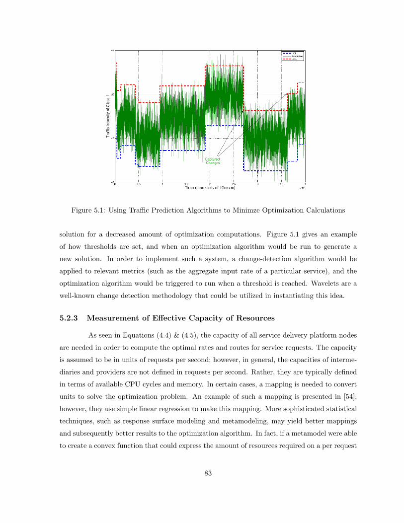
Figure 5.1: Using Traffic Prediction Algorithms to Minimze Optimization Calculations
solution for a decreased amount of optimization computations. Figure 5.1 gives an example
of how thresholds are set, and when an optimization algorithm would be run to generate a
new solution. In order to implement such a system, a change-detection algorithm would be
applied to relevant metrics (such as the aggregate input rate of a particular service), and the
optimization algorithm would be triggered to run when a threshold is reached. Wavelets are a
well-known change detection methodology that could be utilized in instantiating this idea.
5.2.3 Measurement of Effective Capacity of Resources
As seen in Equations (4.4) & (4.5), the capacity of all service delivery platform nodes
are needed in order to compute the optimal rates and routes for service requests. The capacity
is assumed to be in units of requests per second; however, in general, the capacities of interme-
diaries and providers are not defined in requests per second. Rather, they are typically defined
in terms of available CPU cycles and memory. In certain cases, a mapping is needed to convert
units to solve the optimization problem. An example of such a mapping is presented in [54];
however, they use simple linear regression to make this mapping. More sophisticated statistical
techniques, such as response surface modeling and metamodeling, may yield better mappings
and subsequently better results to the optimization algorithm. In fact, if a metamodel were able
to create a convex function that could express the amount of resources required on a per request
83

basis, it could be directly inserted into the optimization problem and enable the algorithm to
reach a more accurate solution than if the simpler constraint set Hy ≤ C were used.
84

Bibliography
[1] US National Academy of Engineering, The Impact of Academic Research on Industrial
Performance. National Academies Press, 2003.
[2] J. Spohrer, P. Maglio, J. Bailey, and D. Gruhl, “Steps Toward a Science of Service Sys-
tems,” IEEE Computer, pp. 71–77, 2007.
[3] M. Endrei, J. Ang, A. Arsanjani, S. Chua, P. Comte, P. Krogdahl, M. Luo, and T. Newling,
Patterns: Service-Oriented Architecture and Web Services. IBM Redbooks, April 2004.
[4] CORBA, Object Management Group, http://www.omg.org/cgi-bin/apps/doc?formal/
04-03-01.pdf.
[5] DCOM, Microsoft Corporation, http://www.microsoft.com/com/default.mspx.
[6] Remote Method Invocation, Sun Microsystems, http://java.sun.com/products/jdk/rmi/.
[7] WebSphere, IBM, http://www-306.ibm.com/software/websphere/.
[8] M. N. Huhns and M. P. Singh, “Service-Oriented Computing: Key Concepts and Princi-
ples,” IEEE Internet Comput., vol. 9, pp. 75–81, Jan-Feb 2005.
[9] M. P. Singh and M. N. Huhns, Service-Oriented Computing: Semantics, Processes, Agents.
John Wiley & Sons, Ltd., 2005.
[10] M. Keen, A. Acharya, S. Bishop, A. Hopkins, S. Milinski, C. Nott, R. Robinson, J. Adams,
and P. Verschueren, Patterns: Implementing an SOA Using an Enterprise Service Bus.
IBM Redbooks, April 2004.
[11] D. Geer, “Will Binary XML Speed Network Traffic?” IEEE Computer, vol. 38, no. 4, pp.
16–18, 2005.
85

[12] Web Services, World Wide Web Consortium, http://www.w3.org/2002/ws/.
[13] D. L. Tennenhouse, J. M. Smith, W. D. Sincoskie, D. J. Wetherall, and G. J. Minden,
“A Survey of Active Network Research,” IEEE Commun. Mag., vol. 35, no. 1, pp. 80–86,
1997.
[14] A. T. Campbell, H. G. D. Meer, M. E. Kounavis, K. Miki, J. B. Vicente, and D. Villela, “A
Survey of Programmable Networks,” ACM SIGCOMM Computer Communication Review,
vol. 29, no. 2, pp. 7–23, 1999.
[15] D. Wetherall, J. Guttag, and D. Tennenhouse, “ANTS: A Toolkit for Building and Dy-
namically Deploying Network Protocols,” in Proceedings of IEEE Conference on Open
Architectures and Network Programming, 1998, pp. 117–129.
[16] David Wetherall, “Active Network Vision and Reality: Lessons from a Capsule-Based
System,” in Proceedings of the 17th ACM Symposium on Operating Systems Principles,
1999.
[17] J. T. Moore, M. W. Hicks, and S. Nettles, “Practical Programmable Packets,” in Proceed-
ings of IEEE INFOCOM, 2001, pp. 41–50.
[18] S. Banerjee, B. Bhattacharjee, and C. Kommareddy, “Scalable Application Layer Multi-
cast,” in Proceedings of ACM SIGCOMM, 2002, pp. 205–217.
[19] XPath, World Wide Web Consortium, http://www.w3.org/TR/xpath.
[20] XSLT, World Wide Web Consortium, http://www.w3.org/TR/xslt.
[21] G. Cuomo, “IBM SOA “on the edge”,” in Proceedings of the ACM SIGMOD International
Conference on Management of Data, 2005, pp. 840–843.
[22] Application Oriented Networking, Cisco Systems, 2005, http://www.cisco.com/en/US/
products/ps6455/index.html.
[23] DataPower, IBM, 2006, http://www-306.ibm.com/software/integration/datapower/.
[24] G. Zhang, “Building a Scalable Native XML Database Engine on Infrastructure for a
Relational Database,” in Proceedings of 2nd International Workshop on XQuery Imple-
mentation, Experience and Perspectives, 2005.
86
[25] M. Welsh, D. Culler, and E. Brewer, “SEDA: An Architecture for Well-Conditioned, Scal-
able Internet Services,” in Proceedings of the 18th ACM Symposium on Operating Systems
Principles, 2001, pp. 230–243.
[26] M. Welsh and D. Culler, “Adaptive Overload Control for Busy Internet Servers,” in Pro-
ceedings of the 4th USENIX Conference on Internet Technologies and Systems, 2003.
[27] M. G. Kallitsis, G. Michailidis, and M. Devetsikiotis, “Pricing and Optimal Resource Allo-
cation in Next Generation Network Services,” in Proceedings of IEEE Sarnoff Symposium,
2007.
[28] ——, “Pricing and Measurement-Based Optimal Resource Allocation in Next Generation
Network Services,” in Proceedings of the First IEEE Workshop on Enabling the Future
Service-Oriented Internet, 2007.
[29] M. G. Kallitsis, R. D. Callaway, M. Devetsikiotis, and G. Michailidis, “Distributed and
Dynamic Resource Allocation for Delay Sensitive Network Services,” in Submitted to IEEE
GLOBECOM, 2008.
[30] M.-T. Schmidt, B. Hutchinson, P. Lambros, and R. Phippen, “The Enterprise Service Bus:
Making service-oriented architecture real,” IBM Systems Journal, vol. 44, 2005.
[31] C. Nott and M. Stockton, “Choose an ESB topology to fit your business model,” in IBM
developerWorks, 2006.
[32] P. Rompothon and T. Senivongse, “A Query Federation of UDDI Registries,” in Proceed-
ings of 1st International ACM Symposium on Information and Communication Technolo-
gies, 2003.
[33] Z. Chen, C. Liang-Tien, B. Silverajan, and L. Bu-Sung, “UX - An Architecture Provid-
ing QoS-Aware and Federated Support for UDDI,” in Proceedings of IEEE International
Conference on Web Services, 2003.
[34] L. Yin, H. Zingli, Z. Futai, and M. Fanyuan, “eDSR: A Decentralized Service Registry for e-
Commerce,” in Proceedings of IEEE International Conference on e-Business Engineering,
2005.
87
[35] S. Banerjee, S. Basu, S. Garg, S. Garg, S.-J. Lee, P. Mullan, and P. Sharma, “Scalable
Grid Service Discovery Based on UDDI,” in Proceedings of the 3rd International Workshop
on Middleware for Grid Computing, 2005, pp. 1–6.
[36] T. Pilioura, G.-D. Kapos, and A. Tsalgatidou, “Seamless Federation of Heterogeneous
Service Registries,” in Proceedings of 5th International Conference on E-Commerce and
Web Technologies, 2004, pp. 86–95.
[37] X. Gu, K. Nahrstedt, and B. Yu, “SpiderNet: An Integrated Peer-to-Peer Service Compo-
sition Framework,” in Proceedings of IEEE International Symposium on High Performance
Distributed Computing, 2004.
[38] L. Baresi and M. Miraz, “A Distributed Approach for the Federation of Heterogeneous
Registries,” in Proceedings of International Conference on Service-Oriented Computing,
2006.
[39] M. Giordano, “DNS-Based Discovery System in Service Oriented Programming,” in Pro-
ceedings of Advances in Grid Computing - EGC, 2005, pp. 840–850.
[40] A. Jagatheesan and S. Helal, “Sangam: Universal Interop Protocols for E-Service Bro-
kering Communities using Private UDDI Nodes,” in Proceedings of IEEE Symposium on
Computers and Communications, 2003.
[41] T. Koponen and T. Virtanen, “A Service Discovery: A Service Broker Approach,” in
Proceedings of 37th Hawaii International Conference on System Sciences, 2004.
[42] N. Limam, J. Ziembicki, R. Ahmed, Y. Iraqi, D. T. Li, R. Boutaba, and F. Cuervo, “OSDA:
Open Service Discovery Architecture for Cross-domain Service Discovery,” in Proceedings
of 2nd International Workshop on Next Generation Networking Middleware, 2005.
[43] M. Walfish, H. Balakrishnan, S. Shenker, K. Lakshminarayanan, S. Ratnasamy, and I. Sto-
ica, “A Layered Naming Architecture for the Internet,” in Proceedings of ACM SIGCOMM,
2004.
[44] J. Chandrashekar, Z.-L. Zhang, Z. Duan, and Y. T. Hou, “Service Oriented Internet,” in
Proceedings of International Conference on Service-Oriented Computing, 2003.
88
[45] R. Ahmed, R. Boutaba, F. Cuervo, Y. Iraqi, T. Li, N. Limam, J. Xiao, and J. Ziembicki,
“Service Naming in Large-Scale and Multi-Domain Networks,” IEEE Communications
Surveys & Tutorials, vol. 7, no. 3, pp. 38–54, 2005.
[46] J. Moy, “OSPF Version 2,” RFC2328, April 1998.
[47] Y. Rekhter, T. Li, and S. Hares, “A Border Gateway Protocol 4 (BGP-4),” RFC4271,
January 2006.
[48] G. Valetto, L. W. Goix, and G. Delaire, “Towards Service Awareness and Autonomic
Features in a SIP-Enabled Network,” in Proceedings of IFIP Workshop on Autonomic
Computing, Oct. 2005, pp. 202–213.
[49] H. Bastiaansen and P. Hermans, “Managing Agility through Service Orientation in an
Open Telecommunication Value Chain,” IEEE Commun. Mag., pp. 86–93, October 2006.
[50] G. Tesauro, D. M. Chess, W. E. Walsh, R. Das, A. Segal, I. Whalley, J. O. Kephart, and
S. R. White, “A Multi-Agent Systems Approach to Autonomic Computing,” in Proceedings
of the 3rd International Joint Conference on Autonomous Agents and Multiagent Systems,
2004, pp. 464–471.
[51] R. D. Callaway, A. Rodriguez, M. Devetsikiotis, and G. Cuomo, “Challenges in Service-
Oriented Networking,” in Proceedings of IEEE GLOBECOM, 2006.
[52] A. Nagurney and J. Dong, Supernetworks. Edward Elgar Publishing, 2002.
[53] M. Walfish, J. Stribling, M. Krohn, H. Balakrishnan, R. Morris, and S. Shenker, “Mid-
dleboxes No Longer Considered Harmful,” in Proceedings of 6th Symposium on Operating
Systems Design and Implementation, 2004, pp. 215–230.
[54] G. Pacifici, W. Segmuller, M. Spreitzer, and A. Tantawi, “Dynamic Estimation of CPU
Demand of Web Traffic,” in Proceedings of 1st International Conference on Performance
Evaluation Methodologies and Tools, October 2006.
[55] R. G. Gallager, “A Minimum Delay Routing Algorithm Using Distributed Computation,”
IEEE Trans. Commun., vol. 23, pp. 73–85, 1977.
[56] S. Vutukury and J. Garcia-Luna-Aceves, “MDVA: A Distance-Vector Multipath Routing
Protocol,” in Proceedings of IEEE INFOCOM, 2001.
89

[57] F. Kelly, “Charging and Rate Control for Elastic Traffic,” in Proceedings of European
Transactions on Telecommunications, vol. 8, January 1997, pp. 33–37.
[58] W.-H. Wan, M. Palaniswami, and S. H. Low, “Application-Oriented Flow Control: Fun-
damentals, Algorithms, and Fairness,” IEEE/ACM Trans. Networking, vol. 14, no. 6, pp.
1282–1291, December 2006.
[59] C. Courcoubetis and R. Weber, Pricing Communication Networks. John Wiley & Sons
Ltd., 2003.
[60] A. Pigou, The Economics of Welfare. Macmillan, London, 1920.
[61] J. G. Wardrop, “Some Theoretical Aspects of Road Traffic Research,” in Proceedings of
the Institute of Civil Engineers, 1952.
[62] H. Yang and H.-J. Huang, Mathematical and Economic Theory of Road Pricing. Elsevier,
2005.
[63] I. C. Paschalidis and J. N. Tsitsiklis, “Congestion-Dependent Pricing of Network Services,”
IEEE/ACM Trans. Networking, 2000.
[64] S. Shenker, D. Clark, D. Estrin, and S. Herzog, “Pricing in Computer Networks: Reshaping
the Research Agenda,” ACM SIGCOMM Computer Communication Review, vol. 26, no. 2,
April 1996.
[65] H. R. Varian and J. K. MacKie-Mason, “Pricing Congestible Network Resources,” IEEE
J. Select. Areas Commun., September 1995.
[66] G. Pacifici, W. Segmuller, M. Spreitzer, M. Steinder, A. Tantawi, and A. Youssef, “Man-
aging the Response Time for Multi-tiered Web Applications,” IBM T.J. Watson Research
Center, Yorktown, NY, Tech. Rep. RC23651, 2005.
[67] M. Falkner, M. Devetsikiotis, and I. Lambadaris, “An Overview of Pricing Concepts for
Broadband IP Networks,” in IEEE Communications Surveys, 2000, pp. 2–13.
[68] D. Thißen, “Load Balancing for the Management of Service Performance in Open Service
Markets: a Customer-Oriented Approach,” in Proceedings of ACM Symposium on Applied
Computing, 2002.
90
[69] V. Machiraju, A. Sahai, and A. van Moorsel, “Web Services Management Network: An
Overlay Network for Federated Service Management,” Hewlett-Packard, Tech. Rep. HPL-
2002-234, 2002.
[70] Z. Duan, Z.-L. Zhang, and Y. T. Hou, “Service Overlay Networks: SLAs, QoS, and Band-
width Provisioning,” IEEE/ACM Trans. Networking, 2003.
[71] Z. Li and P. Mohapatra, “QRON: QoS-Aware Routing in Overlay Networks,” IEEE J.
Select. Areas Commun., 2004.
[72] D. Xu and K. Nahrstedt, “Finding Service Paths in a Media Service Proxy Network,”
in Proceedings of the ACM/SPIE Conference on Multimedia Computing and Networking,
2002.
[73] X. Gu, K. Nahrstedt, R. Chang, and C. Ward, “QoS-Assured Service Composition in
Managed Service Overlay Networks,” in Proceedings of IEEE ICDCS, 2003.
[74] W. Wang and B. Li, “Market-Based Self-Optimization for Autonomic Service Overlay
Networks,” IEEE J. Select. Areas Commun., 2005.
[75] A. Verma and S. Ghosal, “On Admission Control for Profit Maximization of Networked
Service Providers,” in Proceedings of the 12th International Conference on the World Wide
Web. New York, NY, USA: ACM Press, 2003, pp. 128–137.
[76] L. Grit, “Broker Architectures for Service-oriented Systems,” Master’s thesis, Duke Uni-
versity, 2005.
[77] Y. Liu, A. Ngu, and L. Zeng, “QoS Computation and Policing in Dynamic Web Service
Selection,” in Proceedings of WWW, 2004.
[78] E. M. Maximillien and M. P. Singh, “Multiagent System for Dynamic Web Services Se-
lection,” in Proceedings of the AAMAS Workshop on Service-Oriented Computing and
Agent-Based Engineering, 2005.
[79] A.-C. Huang and P. Steenkiste, “Network Sensitive Service Discovery,” in Journal of Grid
Computing, 2004, pp. 309–326.
[80] B. Chaib-draa and J. P. Muller, Eds., Multiagent-Based Supply Chain Management.
Springer, 2006.
91

[81] P. M. Markopoulos and L. H. Ungar, “Shopbots and Pricebots in Electronic Service Mar-
kets,” in Game Theory and Decision Theory in Agent-Based Systems. Kluwer Academic
Publishers, 2001.
[82] P. B. Luh, M. Ni, H. Chen, and L. S. Thakur, “Price-Based Approach for Activity Coor-
dination in a Supply Network,” IEEE Trans. Robot. Automat., vol. 19, no. 2, pp. 335–346,
April 2003.
[83] M. Chiang, S. H. Low, A. R. Calderbank, and J. C. Doyle, “Layering as Optimization
Decomposition: A Mathematical Theory of Network Architectures,” Proc. IEEE, vol. 95,
no. 1, pp. 255–312, January 2007.
[84] J. He, M. Bresler, M. Chiang, and J. Rexford, “Towards Robust Multi-Layer Traffic Engi-
neering: Optimization of Congestion Control and Routing,” IEEE J. Select. Areas Com-
mun., vol. 25, no. 5, June 2007.
[85] J. Wang, L. Li, S. H. Low, and J. C. Doyle, “Cross-Layer Optimization in TCP/IP net-
works,” IEEE/ACM Trans. Networking, vol. 13, no. 3, June 2005.
[86] D. P. Bertsekas, A. Nedic, and A. E. Ozdaglar, Convex Analysis and Optimization. Athena
Scientific, 2003.
[87] D. P. Bertsekas and J. N. Tsitsiklis, Parallel and Distributed Computation: Numerical
Methods. Prentice Hall, 1989.
[88] D. P. Bertsekas, Network Optimization: Continuous and Discrete Models. Athena Scien-
tific, 1998.
[89] D. P. Bertsekas and R. Gallagher, Data Networks. Prentice Hall, 1992.
[90] P. Marbach, “Priority Service and Max-Min Fairness,” IEEE/ACM Trans. Networking,
vol. 11, no. 5, October 2003.
[91] A. Tang, J. Wang, and S. H. Low, “Counter-Intuitive Throughput Behaviors in Networks
Under End-to-End Control,” IEEE/ACM Trans. Networking, vol. 14, no. 2, April 2006.
[92] S. Shenker, “Fundamental Design Issues For the Future Internet,” IEEE J. Select. Areas
Commun., vol. 13, no. 7, September 1995.
92

[93] J.-W. Lee, R. R. Mazumdar, and N. B. Shroff, “Non-Convex Optimization and Rate Con-
trol for Multi-Class Services in the Internet,” IEEE/ACM Trans. Networking, vol. 13,
no. 4, August 2005.
[94] M. Chiang, “Nonconvex Optimization for Communication Systems,” in Advances in Me-
chanics and Mathematics, D. Gao and H. Sherali, Eds. Springer Science+Business Media,
October 2007, vol. 3.
[95] P. Hande, S. Zhang, and M. Chiang, “Distributed rate allocation for inelastic flows,”
IEEE/ACM Trans. Networking, February 2008.
[96] M. Grant and S. Boyd, “CVX: Matlab software for disciplined convex programming,”
February 2008. [Online]. Available: http://stanford.edu/∼boyd/cvx
[97] Y. Li, M. Chiang, and A. R. Calderbank, “Congestion Control in Networks with Delay
Sensitive Traffic,” in Proceedings of IEEE GLOBECOM, November 2007.
[98] National Science Foundation, “NSF NeTS FIND Initiative,” 2006. [Online]. Available:
http://www.nets-find.net/
[99] S. Vutukury and J. Garcia-Luna-Aceves, “MPATH: A Loop-free Multipath Routing Algo-
rithm,” Microprocessors and Microsystems, vol. 24, no. 6, pp. 319–327, October 2000.
93

APPENDIX
94
Appendix A
Intra-Federation Routing Protocol
Specification
A.1 Introduction
This document is a specification of the Intra-Federation Routing Protocol (IFRP).
IFRP is a service-state routing protocol, which means that it distributes service routing infor-
mation among nodes belonging to a single autonomous federation of enterprise service buses.
IFRP is loosely based on the Open Shortest Path First protocol, which enables routing of
requests across the Internet based on their destination IP address.
IFRP is based on the concept of service state information. It has been specifically
designed to be a policy-driven routing protocol that enables autonomic features such as fast
failover, load-balancing, and QoS based routing.
A.1.1 Protocol Overview
IFRP routes messages based upon arbitrary criteria as defined by systems architects
or administrators. It is envisioned that messages would be encapsulated in a transport-agnostic
protocol such as SOAP as they are passed between nodes in the federation. IFRP is a dynamic
routing protocol, in that it quickly detects changes in service state (changes in service metadata)
and the federation topology (node goes down or becomes unreachable), and calculates new
routes after a period of convergence. This period of convergence is short and involves a small
amount of routing traffic.
IFRP allows sets of nodes to be grouped together; groupings are referred to as deploy-
95
ments. Within a deployment, all nodes have an identical service state database. The topology
of a deployment is hidden from the rest of the autonomous federation. The topological informa-
tion is irrelevant, as any node in the deployment is able to route service requests to any service
proxy that exists on any other node in the deployment.
All IFRP messages are authenticated. This means that only trusted nodes can partic-
ipate in service routing within the autonomous federation. A variety of authentication schemes
can be utilized; however, security concerns are not addressed in this specification.
Externally derived service routing data (i.e., routes learned from other autonomous
federations) is advertised throughout the autonomous federation. This externally derived data
is kept logically separate from the IFRP protocol’s data.
A.1.2 The Service State Database
In a service-state routing protocol, each node maintains a database describing the
state of services that are routable. This database is referred to as the service state database
(SSDB). Each node distributes its local service-state throughout the federation according to
the federation’s topology. All nodes run the exact same algorithm in parallel. From the service
state database, nodes can construct data structures that can be used to determine the route of
a request within the autonomous federation.
The SSDB of an autonomous federation describes a list of routable services available
to consumers who utilize the integration infrastructure provided by the federation. IFRP is
responsible for the replication of the service state database within the deployment. Differing
from OSPF, the SSDB does not describe a directed graph.
The SSDB is pieced together from service state advertisements generated by nodes.
These SSAs can provide detailed information about each mediation proxying a service instance,
or can provide summary information such as a route for a particular namespace.
A.1.3 Definitions of Commonly Used Terms
This section provides definitions for terms that have a specific meaning to the IFRP
protocol.
Enterprise Service Bus: a logical architectural component that provides an integration in-
frastructure consistent with the principles of service-oriented architectures.
96
Node: An instance of an enterprise service bus. This could be a hardened SOA appliance
(e.g. WebSphere DataPower) or an instance of a purely software-based solution (e.g.
WebSphere ESB or WebSphere Message Broker).
Deployment: A grouping of one or more nodes in the same autonomous federation that are
under the scope of a single registry.
Autonomous Federation (AF): A collection of one or more deployments, each containing
one or more nodes, which share service routing information via a common routing protocol.
Abbreviated as AF.
Node ID: A number assigned to each node running the IFRP protocol. This number uniquely
identifies the node within the AF.
Service: A discrete function that can be offered to an external customer which is defined by
an explicit interface.
Mediation: A set of operations that are performed by a node before forwarding a message
onto the next hop. A mediation has state information associated with it. A mediation is
also referred to as a service proxy.
Adjacency: A relationship formed between two nodes for the purpose of sharing service routing
information. All nodes in a deployment are adjacent to all other nodes in the deployment.
Service State Advertisement: Unit of data describing the state of a routable service. For a
node, this includes its own service proxies as well as those of adjacent nodes. Abbreviated
as SSA.
Flooding: The part of the IFRP protocol that distributes and synchronizes the SSDB between
IFRP nodes.
Lower-Level Protocols: The underlying network protocols that provide access to the logical
and physical network. Examples of these protocols are TCP, UDP, IP, and Ethernet Data
Link Layer.
A.1.4 Organization of this Document
The first three sections of this document give a high-level overview of the protocol’s
capabilities and functions. Sections A.3-A.12 explain the mechanisms of the protocol in detail.
97
A.2 Splitting the Autonomous Federation into Deployments
IFRP allows collections of nodes to be grouped together. Such a group, together with
services that the nodes provide proxying services for, is called a deployment. Each deploy-
ment runs a separate copy of the basic service-state routing algorithm. This means that each
deployment has its own SSDB.
The topology of a deployment is invisible from the outside of the deployment. Con-
versely, nodes internal to a given deployment know nothing of the detailed topology external
to the deployment. This isolation of knowledge enables the protocol to effect a marked reduc-
tion in routing traffic as compared to treating the entire autonomous federation as a single
service-state domain.
With the introduction of deployments, it is true that all nodes in the AF may not have
an identical SSDB. A node actually has a separate SSDB for each deployment it is connected
to. Nodes connected to multiple deployments are referred to as deployment border nodes.
Two nodes belonging to the same deployment, for that deployment, have identical deployment
SSDBs.
Routing in the AF takes place on two levels, depending on whether a request is serviced
within a deployment (intra-deployment routing) or different deployments (inter-deployment
routing is then used). In intra-deployment routing, the message is routed on service metadata
obtained from within the deployment; no routing information obtained from outside the de-
ployment can be used. This protects intra-deployment routing from the injection of incorrect
routing information. We discuss inter-deployment routing in Section A.2.1.
A.2.1 Inter-Deployment Routing
The path that the request will travel can be broken up into three contiguous pieces: an
intra-deployment path from the source node to a deployment border node, a inter-deployment
path between deployments, and another intra-deployment path to the destination node.
While OSPF has the concept of a backbone, to which all deployment border nodes
would be connected, we deliberately omit this from our specification. This is because nodes
attached to the OSPF backbone have summary knowledge of the routable services available
at every other deployment in the AF. This would be contrary to our goal of having policy-
driven peering relationships between deployments in the federation, which implies that full
dissemination of summary knowledge of deployment routing information, which may not be
98
desirable in all cases.
A.2.2 Classification of Nodes
When the AF is split into one or more deployments, the nodes can be divided into the
following three overlapping categories:
Internal Nodes: A node with all directly hosted services belonging to the same deployment.
These nodes run a single copy of the basic routing algorithm.
Deployment Border Nodes: A node that attaches to multiple deployments. Deployment
border nodes run multiple copies of the basic algorithm, with one copy for each attached
deployment. Deployment border nodes condense the topological information of their
attached deployments for distribution to peer deployments in the federation.
AF Boundary Nodes: A node that exchanges routing information with nodes belonging to
other autonomous federations. Such a node advertises AF external routing information
throughout the AF. This classification is completely independent of the previous classifi-
cations; AF boundary nodes may be internal or deployment border nodes.
A.2.3 Supporting Stub Deployments
In some autonomous federations, the majority of the SSDB may consist of AF-external-
SSAs. An IFRP AF-external-SSA is usually flooded throughout the entire AF. However, IFRP
allows certain deployments to be configured as “stub deployments”. AF-external-SSAs are
not flooded into/throughout stub deployments; routing to AF external destinations in these
deployments is only based on a per-deployment default. This reduces the SSDB size for a stub
deployment’s internal nodes.
In order take advantage of the IFRP stub deployment support, default routing must
be used in the stub deployment. This is accomplished as follows: one or more of the stub
deployment’s deployment border nodes must advertise a default route into the stub deployment
via summary-SSAs. These summary defaults are flooded throughout the stub deployment, but
no further (for this reason, these defaults pertain only to the particular stub deployment).
These summary default routes will be used for any destination that is explicitly reachable by
an intra-deployment or inter-deployment path (i.e. AF external destinations).
99
A deployment can be configured as a stub when there is a single exit point from the
deployment, or when the choice of exit point need not be made on a per-external-destination
basis.
The IFRP protocol ensures that all nodes belonging to a deployment agree on whether
the deployment has been configured as a stub. This guarantees that no confusion will arise in
the flooding of AF-external-SSAs.
AF boundary nodes cannot be placed internal to stub deployments.
A.3 Functional Summary
A separate copy of IFRP’s basic routing algorithm runs in each deployment. Nodes
connected to multiple deployments run multiple copies of the algorithm. A brief summary of
the routing algorithm follows.
When a node starts, it first initializes the routing protocol data structures.
At least one other node in the deployment must be specified a priori. The node sends
Hello messages to the other nodes in the deployment (as defined a priori or as learned through
other nodes in the deployment).
The node will attempt to form adjacencies with all other nodes in the deployment. SS-
DBs are synchronized amongst adjacent nodes. Adjacencies control the distribution of routing
information. Routing updates are only sent and received by adjacenct nodes.
A node periodically advertises its state, which is also called service state. Service
state is also advertised when a node’s state changes. A node’s adjacencies are reflected in the
contents of its SSAs. This relationship between adjacencies and service state allows the protocol
to detect dead nodes in a timely fashion.
SSAs are flooded throughout the deployment. The flooding algorithm is reliable,
ensuring that all nodes in a deployment have exactly the same SSDB. This database consists
of SSAs originated by each node belonging to the deployment. From this database, each node
can calculate a routing table for the protocol.
A.3.1 Inter-Deployment Routing
The previous section described the operation of the protocol within a single deploy-
ment. For intra-deployment routing, no other routing information is pertinent. In order to be
able to route to destinations outside the deployment, the deployment border nodes inject ad-
100
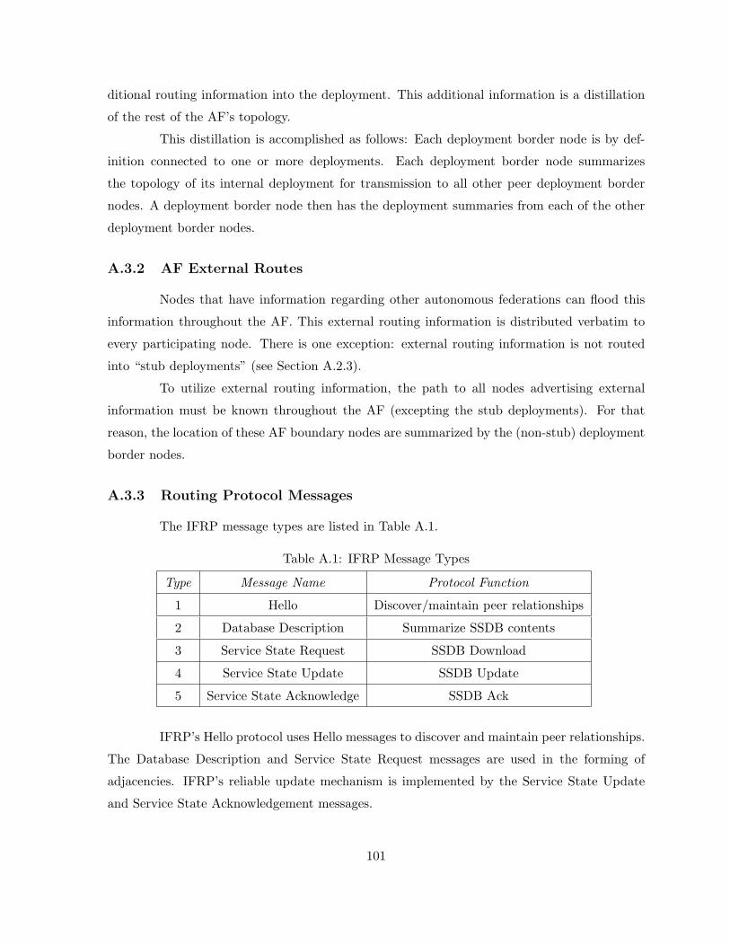
ditional routing information into the deployment. This additional information is a distillation
of the rest of the AF’s topology.
This distillation is accomplished as follows: Each deployment border node is by def-
inition connected to one or more deployments. Each deployment border node summarizes
the topology of its internal deployment for transmission to all other peer deployment border
nodes. A deployment border node then has the deployment summaries from each of the other
deployment border nodes.
A.3.2 AF External Routes
Nodes that have information regarding other autonomous federations can flood this
information throughout the AF. This external routing information is distributed verbatim to
every participating node. There is one exception: external routing information is not routed
into “stub deployments” (see Section A.2.3).
To utilize external routing information, the path to all nodes advertising external
information must be known throughout the AF (excepting the stub deployments). For that
reason, the location of these AF boundary nodes are summarized by the (non-stub) deployment
border nodes.
A.3.3 Routing Protocol Messages
The IFRP message types are listed in Table A.1.
Table A.1: IFRP Message Types
Type Message Name Protocol Function
1 Hello Discover/maintain peer relationships
2 Database Description Summarize SSDB contents
3 Service State Request SSDB Download
4 Service State Update SSDB Update
5 Service State Acknowledge SSDB Ack
IFRP’s Hello protocol uses Hello messages to discover and maintain peer relationships.
The Database Description and Service State Request messages are used in the forming of
adjacencies. IFRP’s reliable update mechanism is implemented by the Service State Update
and Service State Acknowledgement messages.
101
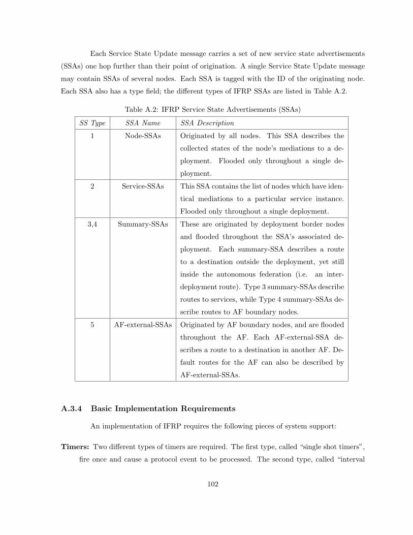
Each Service State Update message carries a set of new service state advertisements
(SSAs) one hop further than their point of origination. A single Service State Update message
may contain SSAs of several nodes. Each SSA is tagged with the ID of the originating node.
Each SSA also has a type field; the different types of IFRP SSAs are listed in Table A.2.
Table A.2: IFRP Service State Advertisements (SSAs)
SS Type SSA Name SSA Description
1 Node-SSAs Originated by all nodes. This SSA describes the
collected states of the node’s mediations to a de-
ployment. Flooded only throughout a single de-
ployment.
2 Service-SSAs This SSA contains the list of nodes which have iden-
tical mediations to a particular service instance.
Flooded only throughout a single deployment.
3,4 Summary-SSAs These are originated by deployment border nodes
and flooded throughout the SSA’s associated de-
ployment. Each summary-SSA describes a route
to a destination outside the deployment, yet still
inside the autonomous federation (i.e. an inter-
deployment route). Type 3 summary-SSAs describe
routes to services, while Type 4 summary-SSAs de-
scribe routes to AF boundary nodes.
5 AF-external-SSAs Originated by AF boundary nodes, and are flooded
throughout the AF. Each AF-external-SSA de-
scribes a route to a destination in another AF. De-
fault routes for the AF can also be described by
AF-external-SSAs.
A.3.4 Basic Implementation Requirements
An implementation of IFRP requires the following pieces of system support:
Timers: Two different types of timers are required. The first type, called “single shot timers”,
fire once and cause a protocol event to be processed. The second type, called “interval
102
timers” fire at continuous intervals. These are used for the sending of messages at regular
intervals. A good example of this is the regular sending of Hello messages to peer nodes.
Interval timers should be implemented to avoid drift. In some node implementations,
message processing can affect timer execution. When multiple nodes are attached in a
single deployment, synchronization of routing messages can occur and should be avoided.
If timers cannot be implemented to avoid drift, small random amounts should be added
to/subtracted from the interval timer at each firing.
Lower-Level Protocol Support: The lower-level protocols referred to here are the network
access protocols, such as the Ethernet data link layer. Indications must be passed from
these protocols to IFRP as the network interface goes up and down. For example, on
an Ethernet it would be valuable to know when the Ethernet transceiver cable becomes
unplugged.
List Manipulation Primitives: Much of the IFRP functionality is described in terms of its
operations on lists of SSAs. For example, the collection of SSAs that will be retransmitted
to an adjacent node until acknowledged are described as a list. Any particular SSA may
be on many such lists. An IFRP implementation needs to be able to manipulate these
lists, adding and deleting constituent SSAs as necessary.
Tasking Support: Certain procedures described in this specification invoke other procedures.
At times, these other procedures should be executed in-line, that is, before the current
procedure is finished. This is indicated in the text by instructions to execute a procedure.
At other times, the other procedures are to be executed only when the current procedure
has finished. This is indicated by instructions to schedule a task.
A.3.5 Optional IFRP Capabilities
The IFRP protocol defines several optional capabilities. A node indicates the op-
tional capabilities that it supports in its IFRP Hello, Database Description, and SSA messages.
This enables nodes supporting a mix of optional capabilities to exist in a single autonomous
federation.
Some capabilities must be supported by all nodes attached to a specific deployment.
In this case, a node will not accept a peer’s Hello message unless there is a match in reported
capabilities (i.e. a capability mismatch prevents a peer relationship from forming). An example
of this is the ExternalRoutingCapability (see below).
103
Other capabilities can be negotiated during the Database Exchange process. This
is accomplished by specifying the optional capabilities in Database Description messages. A
capability mismatch with a peer, in this case, will result in only a subset of the service state
database being exchanged between the two peers.
The routing table build process can also be affected by the presence/absence of optional
capabilities. For example, since the optional capabilities are reported in SSAs, nodes incapable
of certain functions can be avoided when building the routing table.
The IFRP optional capabilities defined in this specification are listed below.
ExternalRoutingCapability: Entire IFRP deployments can be configured as “stubs” (See
Section A.2.3). AF-external-SSAs will not be flooded into stub deployments. This capa-
bility is represented by the E flag in the Hello message.
A.4 Protocol Data Structures
The IFRP protocol is described herein in terms of its operation on various protocol
data structures. The following list comprises the top-level IFRP data structure. Any initial-
ization that needs to be done is noted. IFRP deployments, services, and peers have associated
data structures that are described later in this specification.
Node ID: A number that uniquely identifies a node within the AF. If a node’s IFRP Node ID
is changed, the node’s IFRP software should be restarted before the new Node ID takes
effect. In this case, the node should flush its self-originated SSAs from the routing domain
(See Section A.12.1) before restarting, or they will persist for up to MaxAge minutes.
Deployment Structures: Each one of the deployments to which the node is connected has
its own data structure. This data structure describes the working of the basic IFRP
algorithm. Remember that each deployment runs a separate copy of the IFRP algorithm.
List of External Routes: These are routes to destinations external to the AF, that have been
gained either through direct experience with another routing protocol (such as EFRP),
through configuration information, or through a combination of the two (e.g. dynamic
external information to be advertised over IFRP with configured metric). A node having
these external routes is called an AF boundary node. These routes are advertised by the
node into the IFRP routing domain via AF-external-SSAs.
104
List of AF-external-SSAs: Part of the service state database. These have originated from
the AF boundary nodes. The comprise routes to destinations external to the AF. If the
node is itself an AF boundary node, some of these AF-external-SSAs have been self-
originated.
A.5 The Deployment Data Structure
The deployment data structure contains all the information used to run the basic
IFRP routing algorithm. Each deployment maintains its own SSDB. A service instance belongs
to a single deployment, and at least one node in the deployment acts as a proxy for that service
instance. Each node adjacency also belongs to a single deployment.
The deployment SSDB consists of the collection of node-SSAs, service-SSAs and sum-
mary SSAs that have originated from the deployment’s nodes. This information is flooded
throughout a single deployment only. The list of AF-external-SSAs (see Section A.4) is also
considered to be a part of each deployment’s service state database.
Deployment ID: A number that uniquely identifies the deployment in the AF.
List of Deployment Namespaces: In order to aggregate routing information at deployment
boundaries, deployment namespaces can be employed. Each namespace is specified by
a URI and a status indication of either Advertise or DoNotAdvertise for each inter-
deployment peer relationship.
List of Node-SSAs: A node-SSA is generated by each node in the deployment. It describes
the state of the node’s mediations to the deployment.
List of Service-SSAs: One service-SSA is generated for each mediation in the deployment
by the mediation’s Designated Node. A service-SSA describes the set of nodes that have
identical mediations to a unique service instance.
List of Summary-SSAs: Summary-SSAs originate from the deployment’s deployment border
nodes. They describe routes to destinations internal to the AF, yet external to the
deployment (i.e. inter-deployment destinations).
TransitCapability: This parameter indicates whether the deployment can carry data traffic
that neither originates or terminates in the deployment itself. This parameter is as an
105
input in building the routing table. When a deployment’s TransitCapability is set to
TRUE, the deployment is said to be a transit deployment.
ExternalRoutingCapability: This parameter indicates whether AF-external-SSAs will be
flooded into or throughout a deployment. If AF-external-SSAs are excluded from the
deployment, the deployment is called a “stub”. Within stub deployments, routing to
external destinations will be based solely on a default summary route.
Unless otherwise specified, the remaining sections of this document refer to the oper-
ation of the IFRP protocol within a single deployment.
A.6 Bringing Up Adjacencies
IFRP creates adjacencies between nodes for the purpose of exchanging routing infor-
mation. This section covers the generalities involved in creating adjacencies.
A.6.1 Hello Protocol
The Hello Protocol is responsible for establishing and maintaining peer relationships.
It also ensures that communication between peers are bidirectional. Hello messages are sent
periodically out to all adjacent nodes. Bidirectional communications are indicated when the
node sees itself listed in a peer’s Hello message.
In the Hello Protocol, nodes advertise themselves by periodically sending Hello mes-
sages to their adjacent nodes. These Hello messages contain the list of nodes whose Hello
messages have been seen recently.
The details of the Hello protocol can be found in Sections A.9.4 & A.9.5.
After a peer has been discovered and bidirectional communication is ensured, the first
step is to synchronize the peer’s SSDB. This is covered in Section A.6.2.
A.6.2 The Synchronization of Databases
In a service state routing algorithm, it is very important for all nodes’ service state
databases to stay synchronized. IFRP simplifies this by requiring only adjacent nodes to remain
synchronized. The synchronization process begins as soon as the nodes attempt to establish
a peer relationship. Each node describes its database by sending a sequence of Database
Description messages to its peer. Each Database Description message describes a set of SSAs
106
belonging to the node’s database. When the peer sees an SSA that is more recent than its own
database copy, it makes a note that this newer SSA should be requested.
This sending and receiving of Database Description messages is called the “Database
Exchange Process”. During this process, the two nodes form a master/slave relationship. Each
Database Description message has a sequence number. Database Description messages sent by
the master (polls) are acknowledged by the slave through echoing of the sequence number. Both
polls and their responses contain summaries of service state data. Only the master is allowed
to retransmit Database Description messages. It does so only at fixed intervals, the length of
which is the configured per-mediation constant RxmtInterval.
During and after the Database Exchange Process, each node has a list of those SSAs
for which the peer has more up-to-date instances. These SSAs are requested in Service State
Request messages. Service State Request messages that are not satisfied are retransmitted at
fixed intervals of time RxmtInterval. When the Database Description Process has completed
and all Service State Requests have been satisfied, the databases are deemed synchronized and
the nodes are marked fully adjacent. At this time, the adjacency is fully functional and is
advertised in the two nodes’ node-SSAs.
The adjacency is used by the flooding procedure as soon as the Database Exchange
Process begins. This simplifies database synchronization, and guarantees that it finishes in a
predictable period of time.
A.6.3 The Designated Node
Every mediation in the AF has a Designated Node. The Designated Node (DN)
performs two main functions for the routing protocol:
• The Designated Node originates a service-SSA on behalf of the mediation. This SSA lists
the set of nodes (including the DN itself) currently providing the same mediation to a
unique service instance. The Service State ID for this SSA (see Section A.10.1) is the
Node ID of the DN for the instance.
• The DN becomes adjacent with all other nodes that have the same mediation for the
unique service instance. Since the SSDB is synchronized across adjacencies, the DN plays
a central part in the synchronization process.
The DN is elected by the Hello Protocol. A node’s Hello Message contains its Node
Priority, which is configurable on a per-mediation basis. In general, when a node’s mediation to
107
a service first becomes functional, it checks to see whether there is currently a Designated Node
for the mediation. If there is, it accepts that Designated Node, regardless of its Node Priority.
(This makes it more difficult to predict the identity of the Designated Node, but ensures that
the Designated Node changes less often. See below.)
Otherwise, the node itself becomes a Designated Node if it has the highest Node
Priority in the deployment. A more detailed (and more accurate) description of Designated
Node election is presented in Section A.8.4.
The Designated Node is the endpoint of many adjacencies. Node Priorities should be
configured so that the most dependable node eventually becomes a Designated Node.
A.6.4 The Backup Designated Node
In order to make the transition to a new Designated Node smoother, there is a Backup
Designated Node for each service. The Backup Designated Node is also adjacent to all nodes
with the same mediation, and becomes the Designated Node when the previous Designated
Node fails. If there was no Backup Designated Node, when a new Designated Node became
necessary, new adjacencies would have to be formed between the new Designated Node and all
other nodes with the same mediation. Part of the adjacency forming process is the synchronizing
of service-state databases, which can be a lengthy operation. The Backup Designated Node
obviates the need to form these adjacencies since they already exist. This means the period of
disruption in traffic lasts only as long as it takes to flood the new SSAs (which announce the
new Designated Node).
The Backup Designated Node does not generate a service-SSA for the mediation. (If
it did, the transition to a new Designated Node would be even faster. However, this is a tradeoff
between database size and speed of convergence when the Designated Node disappears.)
In some steps of the flooding procedure, the Backup Designated Node plays a passive
role, letting the Designated Node do more of the work. This cuts down on the amount of local
routing traffic.
A.7 Protocol Message Processing
This section discusses the general processing of IFRP routing protocol messages. It
is very important that the node service state databases remain synchronized. For this reason,
routing protocol messages should get preferential treatment over ordinary messages, both in
108
sending and receiving.
Routing protocol messages are sent along adjacencies only (with the exception of Hello
messages, which are used to discover adjacencies).
All routing protocol messages begin with a standard header. The sections below
provide details on how to fill in and verify this standard header. Then, for each message type,
the section giving more details on that particular message type’s processing is listed.
A.7.1 Sending Protocol Messages
When a node sends a routing protocol message, it fills in the fields of the standard
IFRP message header as follows.
Version #: Set to 1, the version number of the protocol as documented in this specification.
Message Type: The type of IFRP message, such as Service State Update or Hello message.
Node ID: The identity of the node itself that is originating the message.
Deployment ID: The IFRP deployment into which the message is being sent.
A.7.2 Receiving Protocol Messages
When a IFRP message is received, the IFRP protocol header is verified. The fields
specified in the header must match those configured; if they do not, the message should be
discarded.
• The Version number must specify protocol version 1.
• The Deployment ID found in the IFRP header must be verified. If the Deployment ID in
the header does not match a deployment for which the receiving node is a member, then
the message should be discarded.
• The Message Type must be of a supported type as described in Section A.3.3.
If the message type is Hello, it should be then further processed by the Hello protocol
(see Section A.9.5). All other message types are sent/received only on adjacencies. This means
that the messages must have been sent by one of the node’s active peers. The sender is identified
by the Node ID in the message’s header. Each node maintains a list of active peers. Messages
not matching any active peers are discarded.
At this point, all received protocol messages are associated with an active peer.
109
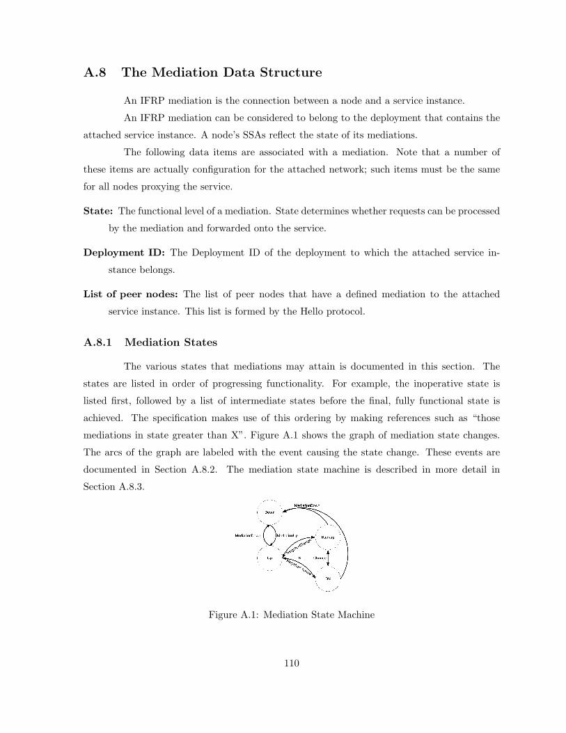
A.8 The Mediation Data Structure
An IFRP mediation is the connection between a node and a service instance.
An IFRP mediation can be considered to belong to the deployment that contains the
attached service instance. A node’s SSAs reflect the state of its mediations.
The following data items are associated with a mediation. Note that a number of
these items are actually configuration for the attached network; such items must be the same
for all nodes proxying the service.
State: The functional level of a mediation. State determines whether requests can be processed
by the mediation and forwarded onto the service.
Deployment ID: The Deployment ID of the deployment to which the attached service in-
stance belongs.
List of peer nodes: The list of peer nodes that have a defined mediation to the attached
service instance. This list is formed by the Hello protocol.
A.8.1 Mediation States
The various states that mediations may attain is documented in this section. The
states are listed in order of progressing functionality. For example, the inoperative state is
listed first, followed by a list of intermediate states before the final, fully functional state is
achieved. The specification makes use of this ordering by making references such as “those
mediations in state greater than X”. Figure A.1 shows the graph of mediation state changes.
The arcs of the graph are labeled with the event causing the state change. These events are
documented in Section A.8.2. The mediation state machine is described in more detail in
Section A.8.3.
Figure A.1: Mediation State Machine
110

Down: This is the initial mediation state. In this state, either the lower level protocols or
service monitoring mechanism has indicated that the mediation is unusable. No requests
will be forwarded to a mediation in this state.
Up: This is one of three functional operating states for a mediation. In this state, requests can
be forwarded to a mediation for processing and eventual forwarding to a service instance.
In this state, the node has not been elected as either Designated Node or as Backup
Designated Node for this mediation.
Backup: This is also one of the three functional operating states for a mediation. In this
state, requests can be forwarded to a mediation for processing and eventual forwarding
to a service instance. In this state, the node itself is the Backup Designated Node for
the mediation. It will be promoted to Designated Node when the present Designated
Node fails. The Backup Designated Node performs slightly different functions during
the Flooding Procedure, as compared to the Designated Node (see Section A.11.3). See
Section A.6.4 for more details on the functions performed by the Backup Designated
Node.
DN: This is also one of the three functional operating states for a mediation. In this state,
requests can be forwarded to a mediation for processing and eventual forwarding to a
service instance. In this state, this node itself is the Designated Node for this mediation.
The node must also originate a service-SSA for the mediation. The service-SSA will
contain a list of all nodes (including the Designated Node itself) containing the mediation.
See Section A.6.3 for more details on the functions performed by the Designated Node.
A.8.2 Events Causing Mediation State Changes
State changes can be effected by a number of events. These events are pictured as the
labeled arcs in Figure A.1. The label definitions are listed below. For a detailed explanation of
the effect of these events on IFRP protocol operation, consult Section A.8.3.
MediationUp: Lower-level protocols or a service monitoring mechanism has indicated that the
mediation to the service instance is operational. This event is triggered upon discovering
that all required operational prerequisites for the mediation processing are functional.
This enables the mediation to transition out of Down state.
111

MediationDown: Lower-level protocols or a service monitoring mechanism has indicated that
the mediation is no longer functional. The failure or the lack of existance of a required
operational prerequisite can also trigger this event. Upon the firing of this event, the state
of the mediation is forced to Down.
NeighborChange: There has been a change in the set of peers who implement this mediation.
The (Backup) Designated Node needs to be recalculated. The following peer changes lead
to the NeighborChange event. For an explanation of peer states, see Section A.9.1.
• Communication has been established with a peer. In other words, the state of the
peer has transitioned to 2-Way or higher.
• There is no longer bidirectional communication with a peer. In other words, the
state of the peer has transitioned to Init or lower.
• One of the peers is newly declaring itself as either Designated Node or Backup Des-
ignated Node. This is detected through examination of that peer’s Hello messages.
• One of the peers is no longer declaring itself as Designated Node, or is no longer
declaring itself as Backup Designated Node. This is again detected through exami-
nation of that peer’s Hello messages.
• The advertised Node Priority for a peer has changed. This is again detected through
examination of that peer’s Hello messages.
A.8.3 The Mediation State Machine
A detailed description of the mediation state changes follows. Each state change is
invoked by an event (Section A.8.2). This event may produce different effects, depending on the
current state of the mediation. For this reason, the state machine below is organized by current
mediation state and received event. Each entry in the state machine describes the resulting
mediation state and the required set of additional actions.
When a mediation’s state changes, it may be necessary to originate a new node-SSA.
See Section A.10.3 for more details.
Some of the required actions below involve generating events for the peer state ma-
chine.
112
Table A.3: Mediation State Transitions
Action:
State(s): Down
Event: MediationUp
New State: Up
If needed, send out a node-SSA to advertise
the availability of this mediation to provide
forwarding to the service instance.
State(s): Any state
Event: MediationDown
New State: Down
Forwarding requests to the mediation are no
longer allowed, as the mediation is now dis-
abled.
State(s): Up, Backup, or DN
Event: MediationDown
New State: Depends on result of election
Recalculate the mediation’s Backup Desig-
nated Node and Designated Node, as shown
in Section A.8.4. As a result of this calcu-
lation, the new state of the interface will be
either Up, Backup, or DN.
A.8.4 Electing the Designated Node
This section describes the algorithm used for calculating a mediation’s Designated
Node and Backup Designated Node. This algorithm is invoked by the Mediation state machine.
The initial time a node runs the election algorithm for a mediation, the mediation’s Designated
Node and Backup Designated Node are initialized to NONE. This indicates the lack of both a
Designated Node and a Backup Designated Node.
The Designated Node election algorithm proceeds as follows: call the node doing the
calculation Node X. The list of peers containing an identical mediation and having established
bidirectional communication with Node X is examined. This list is precisely the collection of
Node X’s peers (with this mediation) whose state is greater than or equal to 2-Way (see Section
A.9). Node X itself is also considered to be on the list. Discard all nodes from the list that
are ineligible to become Designated Node. (Nodes having Node Priority of 0 are ineligible to
become Designated Node.) The following steps are then executed, considering only those nodes
that remain on the list:
1. Note the current values for the mediation’s Designated Node and Backup Designated
Node. This is used later for comparison purposes.
2. Calculate the new Backup Designated Node for the mediation as follows. Only those
113

nodes on the list that have not declared themselves to be Designated Node are eligible to
become Backup Designatd Node. If one or more of these nodes have declared themselves
Backup Designated Node (i.e., they are currently listing themselves as Backup Designated
Node, but not as Designated Node, in their Hello Messages) the one having highest Node
Priority is declared to be Backup Designated Node. In case of a tie, the one having the
highest Node ID is chosen. If no nodes have declared themselves Backup Designated
Node, choose the node having highest Node Priority, (again excluding those node who
have declared themselves Designated Node), and again use the Node ID to break ties.
3. Calculate the new Designated Node for the mediation as follows. If one or more of the
nodes have declared themselves Designated Node (i.e., they are currently listing them-
selves as Designated Node in their Hello Messages) the one having highest Node Priority
is declared to be Designated Node. In case of a tie, the one having the highest Node ID
is chosen. If no nodes have declared themselves Designated Node, assign the Designated
Node to be the same as the newly elected Backup Designated Node.
4. If Node X is now newly the Designated Node or newly the Backup Designated Node, or
is now no longer the Designated Node or no longer the Backup Designated Node, repeat
steps 2 and 3, and then proceed to step 5. For example, if Node X is now the Designated
Node, when step 2 is repeated X will no longer be eligible for Backup Designated Node
election. Among other things, this will ensure that no node will declare itself both Backup
Designated Node and Designated Node.
5. As a result of these calculations, the node itself may now be Designated Node or Backup
Designated Node. See Sections A.6.3 and A.6.4 for the additional duties this would entail.
The node’s mediation state should be set accordingly. If the node itself is now Designated
Node, the new mediation state is DN. If the node itself is now Backup Designated Node,
the new mediation state is Backup. Otherwise, the new mediation state is Up.
The reason behind the election algorithm’s complexity is the desire for an orderly
transition from Backup Designated Node to Designated Node when the current Designated
Node fails.
This orderly transition is ensured through the introduction of hysteresis: no new
Backup Designated Node can be chosen until the old Backup accepts its new Designated Node
responsibilities.
114
The above procedure may elect the same node to be both Designated Node and Backup
Designated Node, although that node will never be the calculating node (Node X) itself. The
elected Designated Node may not be the node having the highest Node Priority, nor will the
Backup Designated Node necessarily have the second highest Node Priority. If Node X is not
itself eligible to become Designated Node, it is possible that neither a Backup Designated Node
nor a Designated Node will be selected in the above procedure. Note also that if Node X is the
only attached node that is eligible to become Designated Node, it will select itself as Designated
Node and there will be no Backup Designated Node for the network.
A.9 The Peer Data Structure
An IFRP node converses with its peer nodes. Each separate conversation is described
by a “peer data structure”. Each conversation is identified by the peer node’s IFRP Node ID.
The peer data structure contains all the information pertinent to the forming or formed
adjacency between the two peers.
State: The functional level of the peer conversation. This is described in more detail in Section
A.9.1.
Inactivity Timer: A single shot timer; when it is fired, it indicates that no Hello message has
been seen from this peer recently. The length of the time is NodeDeadInterval seconds.
Master/Slave: When the two peers are exchanging databases, they first form a master/slave
relationship. The master sends the first Database Description message, and the slave can
only respond to the master’s Database Description messages. The master/slave relation-
ship is negotiated in state ExStart.
DD Sequence Number: The DD Sequence Number of the Database Description message
that is currently being sent to the peer.
Peer ID: The IFRP Node ID of the peer node. The Peer ID is learned when Hello messages
are received from the peer.
Peer URL: The URL of the peer node’s IFRP protocol instance. Used as the Destination
URL when protocol messages are sent to the peer.
115
Peer Options: The optional IFRP capabilities supported by the peer. Learned during the
Database Exchange process (See Section A.9.6). The peer’s optional IFRP capabilities
are also listed in its Hello messages. This enables received Hello messages to be rejected if
there is a mismatch in certain crucial IFRP capabilities (See Section A.9.5). The optional
IFRP capabilities are documented in Section A.3.5.
The next set of variables are sets of SSAs. These lists describe the subsets of the
deployment’s SSDB. This memo defines 5 distinct types of SSAs, all of which may be present in
a deployment SSDB: node-SSAs, service-SSAs, Type 3 & 4 summary-SSAs, and AF-external-
SSAs.
Service State Retransmission List: The list of SSAs that have been flooded but not ac-
knowledged on this adjacency. These will be retransmitted at intervals until they are
acknowledged, or until the adjacency is destroyed.
Database Summary List: The complete list of SSAs that make up the deployment’s SSDB,
at the moment the peer goes into Database Exchange state. This list is sent to the peer
in Database Description messages.
Service State Request List: The list of SSAs that need to be received from this peer to
synchronize the two peer’s service state databases. This list is created as Database De-
scription messages are received, and is then sent to the peer in Service State Request
messages. The list is depleted as appropriate Service State Update messages are received.
A.9.1 Peer States
The state of a peer (actually, the state of a conversation being held with a peer node) is
documented in the following sections. The states are listed in order of progressing functionality.
For example, the inoperative state is listed first, followed by a list of intermediate states before
the final, fully functional state is achieved. The specifications make use of this ordering by
sometimes making references such as “those peers/adjacencies in state greater than X”. Figure
A.2 shows the graph of peer state changes. The arcs of the graphs are labeled with the event
causing the state change. The peer events are documented in Section A.9.2.
The graph in Figure A.2 shows both the state changes effected by the Hello protocol,
which is responsible for peer acquisition and maintenance, and for ensuring two-way communi-
cations between peers. Figure A.2 also shows the forming of an adjacency. The adjacency starts
116
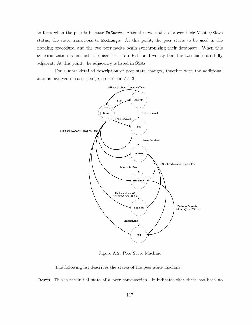
to form when the peer is in state ExStart. After the two nodes discover their Master/Slave
status, the state transitions to Exchange. At this point, the peer starts to be used in the
flooding procedure, and the two peer nodes begin synchronizing their databases. When this
synchronization is finished, the peer is in state Full and we say that the two nodes are fully
adjacent. At this point, the adjacency is listed in SSAs.
For a more detailed description of peer state changes, together with the additional
actions involved in each change, see section A.9.3.
Figure A.2: Peer State Machine
The following list describes the states of the peer state machine:
Down: This is the initial state of a peer conversation. It indicates that there has been no
117
recent information received from the peer.
Attempt: This state indicates that no recent information has been received from a peer, but
that a more concerted effort should be made to contact the neighbor. This is done by
sending the peer Hello messages at intervals of HelloInterval (see Section A.9.4)
Init: In this state, a Hello message has recently been seen from the peer. However, bidirectional
communication has not yet been established with the peer (i.e., the node itself did not
appear in the peer’s Hello message). All peers in this state (or higher) are listed in the
Hello messages sent out from this node.
2-Way: In this state, communication between the two nodes is bidirectional. This has been
assured by the operation of the Hello protocol. This is the most advanced state short of
beginning adjacency establishment.
ExStart: This is the first step in creating an adjacency between two peer nodes. The goal of
this step is to decide which node is the master, and to decide on the initial DD sequence
number.
Exchange: In this state, the node is describing its entire service state database by sending
Database Description messages to the peer. Each Database Description message has a DD
sequence number, and is explicitly acknowledged. Only one Database Description message
is allowed to be outstanding at any one time. In this state, Service State Request messages
may also be sent asking for the peer’s more recent SSAs. All adjacencies in Exchange
state or greater are used by the flooding procedure. In fact, these adjacencies are fully
capable of transmitting and recieving IFRP routing protocol messages.
Loading: In this state, Service State Request messages are sent to the peer asking for the more
recent SSAs that have been discovered (but not yet received) in the Exchange state.
Full: In this state, the peer nodes are fully adjacent. These adjacencies will not appear in
node-SSAs and service-SSAs.
A.9.2 Events Causing Peer State Changes
State changes can be effected by a number of events. These events are shown in the
labels of Figure A.2. The label definitions are as follows:
118
HelloReceived: A Hello message has been received from the peer.
Start: This is an indication that Hello messages should now be sent to the peer at intervals of
HelloInterval seconds.
2-WayReceived: Bidirectional communication has been realized between the two peering
nodes. This is indicated by the node seeing itself in the peer’s Hello message.
NegotiationDone: The Master/Slave relationship has been negotiated, and DD sequence
numbers have been exchanged. This signals the start of the sending/receving of Database
Description messages. For more information on the generation of this event, consult
Section A.9.8.
ExchangeDone: Both nodes have successfully transmitted Database Description messages.
Each node now knows what parts of its SSDB are out of date. For more description on
the generation of this event, consult Section A.9.8.
BadSSReq: A Service State Request has been received for an SSA not contained in the
database. This indicates an error in the Database Exchange process.
LoadingDone: Service State Updates have been received for all out-of-date portions of the
database. This is indicated by the Service State Request List becoming empty after the
Database Exchange process has completed.
The following events cause well-developed peers to revert to lesser states. Unlike the
above events, these events may occur when the peer conversation is in any of a number of states.
SeqNumberMismatch: A Database Description message has been received that either has an
unexpected DD sequence number or has an Options field differing from the last Options
field received in a Database Description message. Either of these conditions indicates that
some error occurred during adjacency establishment.
1Way: A Hello message has been received from the peer, in which the node is not mentioned.
this indicates that communication with the neighbor is not bidirectional.
KillPeer: This is an indication that all communication with the peer is now impossible, forcing
the peer to revert to Down state.
119

InactivityTimer: The inactivity timer has fired. This means that no Hello messages have
been seen recently from the peer. The peer reverts to Down state.
LLDown: This in an indication from the lower level protocols that the neighbor is now un-
reachable. This event forces the peer into Down state.
A.9.3 The Peer State Machine
A detailed description of the peer state changes follows. Each state change is invoked
by an event (Section A.9.2). This event may produce different effects, depending on the current
state of the neighbor. For this reason, the state machine below is organized by current peer
state and received event. Each entry in the state machine describes the resulting new peer state
and required set of additional actions.
When the peer state machine needs to invoke the mediation state machine, it should
be done as a scheduled task (see Section A.3.4). This simplifies things by ensuring that neither
state machine will be executed recursively.
The following is a list of the state machine transitions, and the conditions under which
they will occur:
Table A.4: Peer State Transitions
Action:
State(s): Down
Event: Start
New State: Attempt
Send a Hello message to the peer and start the
peer’s InactivityTimer. The later firing of the
timer would indicate that communication with the
peer was not obtained.
State(s): Attempt
Event: HelloReceived
New State: Init
Restart the InactivityTimer for the peer, since
the peer has now been heard from.
State(s): Down
Event: HelloReceived
New State: Init
Start the InactivityTimer for the peer. The later
firing of the timer would indicate that the peer is
dead.
State(s): Init or greater
Event: HelloReceived
New State: No state change
Restart the InactivityTimer for the peer, since
the peer has again been heard from.
120
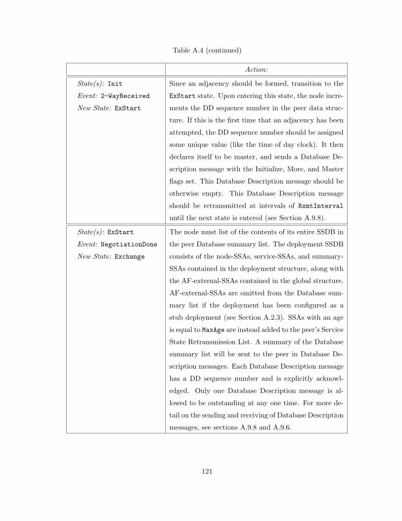
Table A.4 (continued)
Action:
State(s): Init
Event: 2-WayReceived
New State: ExStart
Since an adjacency should be formed, transition to the
ExStart state. Upon entering this state, the node incre-
ments the DD sequence number in the peer data struc-
ture. If this is the first time that an adjacency has been
attempted, the DD sequence number should be assigned
some unique value (like the time of day clock). It then
declares itself to be master, and sends a Database De-
scription message with the Initialize, More, and Master
flags set. This Database Description message should be
otherwise empty. This Database Description message
should be retransmitted at intervals of RxmtInterval
until the next state is entered (see Section A.9.8).
State(s): ExStart
Event: NegotiationDone
New State: Exchange
The node must list of the contents of its entire SSDB in
the peer Database summary list. The deployment SSDB
consists of the node-SSAs, service-SSAs, and summary-
SSAs contained in the deployment structure, along with
the AF-external-SSAs contained in the global structure.
AF-external-SSAs are omitted from the Database sum-
mary list if the deployment has been configured as a
stub deployment (see Section A.2.3). SSAs with an age
is equal to MaxAge are instead added to the peer’s Service
State Retransmission List. A summary of the Database
summary list will be sent to the peer in Database De-
scription messages. Each Database Description message
has a DD sequence number and is explicitly acknowl-
edged. Only one Database Description message is al-
lowed to be outstanding at any one time. For more de-
tail on the sending and receiving of Database Description
messages, see sections A.9.8 and A.9.6.
121
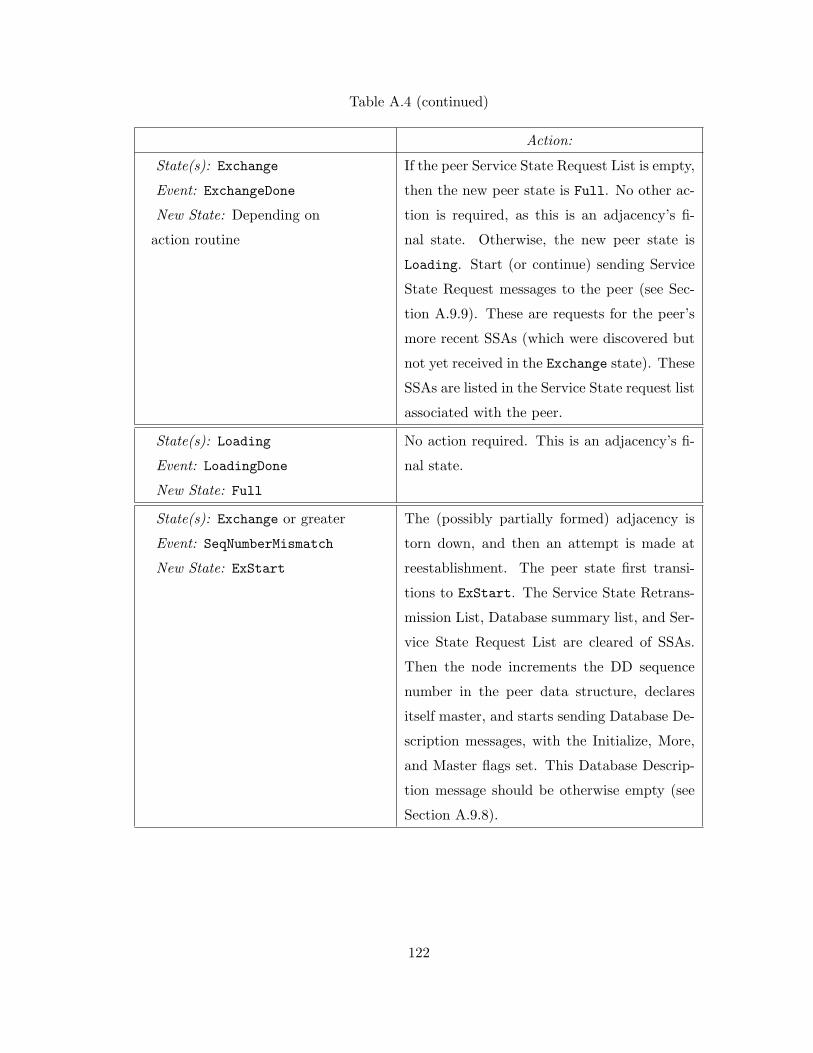
Table A.4 (continued)
Action:
State(s): Exchange
Event: ExchangeDone
New State: Depending on
action routine
If the peer Service State Request List is empty,
then the new peer state is Full. No other ac-
tion is required, as this is an adjacency’s fi-
nal state. Otherwise, the new peer state is
Loading. Start (or continue) sending Service
State Request messages to the peer (see Sec-
tion A.9.9). These are requests for the peer’s
more recent SSAs (which were discovered but
not yet received in the Exchange state). These
SSAs are listed in the Service State request list
associated with the peer.
State(s): Loading
Event: LoadingDone
New State: Full
No action required. This is an adjacency’s fi-
nal state.
State(s): Exchange or greater
Event: SeqNumberMismatch
New State: ExStart
The (possibly partially formed) adjacency is
torn down, and then an attempt is made at
reestablishment. The peer state first transi-
tions to ExStart. The Service State Retrans-
mission List, Database summary list, and Ser-
vice State Request List are cleared of SSAs.
Then the node increments the DD sequence
number in the peer data structure, declares
itself master, and starts sending Database De-
scription messages, with the Initialize, More,
and Master flags set. This Database Descrip-
tion message should be otherwise empty (see
Section A.9.8).
122
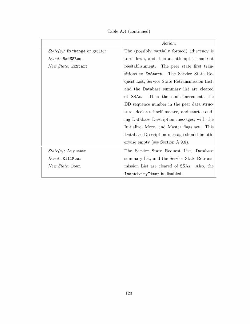
Table A.4 (continued)
Action:
State(s): Exchange or greater
Event: BadSSReq
New State: ExStart
The (possibly partially formed) adjacency is
torn down, and then an attempt is made at
reestablishment. The peer state first tran-
sitions to ExStart. The Service State Re-
quest List, Service State Retransmission List,
and the Database summary list are cleared
of SSAs. Then the node increments the
DD sequence number in the peer data struc-
ture, declares itself master, and starts send-
ing Database Description messages, with the
Initialize, More, and Master flags set. This
Database Description message should be oth-
erwise empty (see Section A.9.8).
State(s): Any state
Event: KillPeer
New State: Down
The Service State Request List, Database
summary list, and the Service State Retrans-
mission List are cleared of SSAs. Also, the
InactivityTimer is disabled.
123
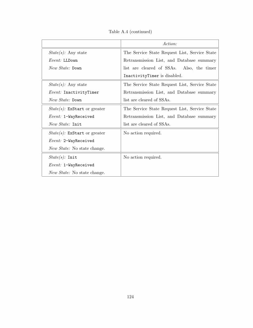
Table A.4 (continued)
Action:
State(s): Any state
Event: LLDown
New State: Down
The Service State Request List, Service State
Retransmission List, and Database summary
list are cleared of SSAs. Also, the timer
InactivityTimer is disabled.
State(s): Any state
Event: InactivityTimer
New State: Down
The Service State Request List, Service State
Retransmission List, and Database summary
list are cleared of SSAs.
State(s): ExStart or greater
Event: 1-WayReceived
New State: Init
The Service State Request List, Service State
Retransmission List, and Database summary
list are cleared of SSAs.
State(s): ExStart or greater
Event: 2-WayReceived
New State: No state change.
No action required.
State(s): Init
Event: 1-WayReceived
New State: No state change.
No action required.
124

A.9.4 Sending Hello Messages
Hello messages are sent out to all peer nodes, as they are used to establish and maintain
peer relationships. The Hello message contains the interval between Hello messages sent between
peers (HelloInterval). The Hello message also indicates how often the peer must be heard
from in order to remain active (NodeDeadInterval).
The Hello message’s Options field describes the node’s optional IFRP capabilities.
One optional capability is described in this specification (see Sections A.3.5). The E-flag of
the Options field should be set if and only if the attached deployment is capable of processing
AF-external-SSAs (i.e. it is not a stub deployment). If the E-flag is set incorrectly, the peer
nodes will refuse to accept the Hello message. (See Section A.9.5).
In order to ensure two-way communication between adjacent nodes, the Hello message
contains the list of all nodes in the deployment from which Hello messages have been seen lately.
Separate Hello messages are sent to each attached peer every HelloInterval seconds.
A.9.5 Receiving Hello Messages
This section explains the detailed processing of a received Hello message. The generic
input processing of IFRP messages will have checked the validity of the message. Next, the
values of the HelloInterval and NodeDeadInterval fields in the received Hello message must
be checked against the values configured for the peer. Any mismatch causes processing to stop
and the message to be dropped.
The setting of the E-flag found in the Hello message’s options field must match this
deployment’s ExternalRoutingCapability. If AF-external-SSAs are not flooded into/throughout
the deployment (i.e. the deployment is a “stub”) the E-flag must be clear in received Hello
messages, otherwise the E-flag must be set. A mismatch causes processing to stop and the
message to be dropped. The setting of the rest of the options in the Options field should be
ignored.
At this point, an attempt is made to match the source of the Hello message to one of
the existing peers. The source is identified by the Node ID found in the Hello message header.
The peers current list of peers is found in the node data structure. If a matching peer data
structure cannot be found (i.e. this is the first time the peer has been detected), one is created.
The initial state of a newly created peer data structure is set to Down.
The remainder of the Hello message is now examined, generating events to be given
125
to the peer state machine. This events directed at this state machine are specified to be
either directly executed inline or scheduled for execution (see Section A.3.4). For example, by
specifying below that the peer state machine be executed inline, several peer state transitions
may be effected by a single received Hello message:
• Each Hello message causes the peer state machine to be executed with the event
HelloReceived.
• Then the list of peers contained in the Hello message is examined. If the node itself appears
in this list, the peer state machine should be executed with the event 2-WayReceived.
Otherwise, the peer state machine should be executed with the event 1-WayReceived,
and the processing of the message stops.
• The receipt of a Hello message causes a Hello message to be sent back to the peer in
response. See Section A.9.4 for more details.
A.9.6 Receiving Database Description Messages
This section explains the detailed processing of a received Database Description mes-
sage. The incoming Database Description message has already been associated with a peer
by the generic input message processing (Section A.7.2). Whether the Database Description
message should be accepted, and if so, how it should be further processed, depends on the peer
state.
If a Database Description message is accepted, the following fields should be saved
in the corresponding peer data structure under “last received Database Description message”:
the message’s initialize, more, master flags, Options field, and DD sequence number. If these
fields are set identically in two consecutive Database Description messages received from the
peer, the second Database Description message is considered to be a duplicate in the processing
described below.
If the peer state is:
Down: The message should be rejected.
Attempt: The message should be rejected.
Init: The peer state machine should be executed with the event 2-WayReceived. This causes
an immediate state change to either state 2-Way or ExStart. If the new state is ExStart,
126
the processing of the current message should then continue in this new state by falling
through to case ExStart below.
2-Way: The message should be ignored. Database Description messages are used only for the
purpose of bringing up adjacencies.
ExStart: If the received message matches one of the following cases, then the neighbor state
machine should be executed with the event NegotiationDone (causing the state to tran-
sition to Exchange), the message’s Options field should be recorded in the peer structure’s
Peer Options field and the message should be accepted as next in sequence and processed
further. Otherwise the message should be ignored.
• The initialize, more, and master flags are set, the contents of the message are empty,
and the peer’s Node ID is larger than the node’s own. In this case, the node is
now Slave. Set the master/slave flag to slave, and set the peer data structure’s DD
sequence number to that specified by the master.
• The initialize and master flags are off, the message’s DD sequence number equals the
peer data structure’s DD sequence number (indicating acknowledgement) and the
peer’s Node ID is smaller than the node’s own. In this case, the node is the Master.
Exchange: Duplicate Database Description messages are discarded by the master, and cause
the slave to retransmit the last Database Description message that it had sent. Otherwise
(the message is not a duplicate):
• If the state of the master/slave flag is inconsistent with the master/slave state of the
connection, generate the peer event SeqNumberMismatch and stop processing the
message.
• If the initialize flag is set, generated the peer event SeqNumberMismatch and stop
processing the message.
• If the message’s Options field indicates a different set of optional IFRP capabilities
than were previously received from the peer (recorded in the Peer Options field of
the peer structure), generate the peer event SeqNumberMismatch and stop processing
the message.
• Database Description messages must be processed in sequence, as indicated by the
messages’ DD sequence numbers. If the node is master, the next message received
127
should have DD sequence number equal to the DD sequence number in the peer data
structure. If the node is slave, the next message received should have DD sequence
number equal to one more than the DD sequence number stored in the peer data
structure. In either case, if the message is next in sequence it should be accepted
and its contents processed as specified below.
• Else, generate the peer event SeqNumberMismatch and stop processing the message.
Loading or Full: In this state, the node has sent and received an entire sequence of Database
Description messages. The only messages received should be duplicates (see above). In
particular, the message’s Options field should match the set of optional IFRP capabilities
previously indicated by the peer (stored in the peer structure’s Peer Options field). Any
other messages received, including the reception of a message with the Initialized flag set,
should generated the peer event SeqNumberMismatch. Duplicates should be discarded
by the master. The slave must respond to duplicates by repeating the last Database
Description message that it had sent.
When the node accepts a received Database Description message as the next in se-
quence, the message contents are processed as follows: For each SSA listed, the SSA’s SS type
is checked for validity. If the SS type is unknown (e.g. not one of the SS types 1-5 defined by
this specification), or if this is an AF-external-SSA (SS type = 5) and the peer is associated
with a stub deployment, generate the peer event SeqNumberMismatch and stop processing the
message. Otherwise, the node looks up the SSA in its database to see whether it has an instance
of SSA. If it does not, or if the database copy is less recent (see Section A.11.1), the SSA is
put on the Service State Request list so that it can be requested (immediately or at some later
time) in Service State Request messages.
When the node accepts a received Database Description message as the next in se-
quence, it also performs the following actions, depending on whether it is master or slave:
Master: Increments the DD sequence number in the peer data structure. If the node has
already sent its entire sequence of Database Description messages, and the just-accepted
message has the more flag set to none, the peer event ExchangeDone is generated. Oth-
erwise it should sent a new Database Description to the slave.
Slave: Sets the DD sequence number in the peer data structure to the DD sequence number
appearing in the received message. The slave must send a Database Description message
128
in reply. If the received message has the more flag set to none, and the message to be
sent by the slave will also have the more flag set to none, the peer event ExchangeDone
is generated. Note that the slave always generates this event before the master.
A.9.7 Receiving Service State Request Messages
This section explains the detailed processing of received Service State Request mes-
sages. Received Service State Request messages specify a list of SSAs that the peer wishes to
receive. Service State Request messages should be accepted when the peer is in states Exchange,
Loading, or Full. In all other states, Service State Request messages should be ignored.
Each SSA specified in the Service State Request message should be located in the
node’s database and copied into Service State Update messages for transmission to the peer.
These SSAs should NOT be placed on the Service State Retransmission List for the peer. If an
SSA cannot be found in the database, something has gone wrong with the Database Exchange
process, and the peer event BadSSReq should be generated.
A.9.8 Sending Database Description Messages
This section describes how Database Description messages are sent to a peer. The
node’s optional IFRP capabilities are transmitted to the peer in the Options field of the
Database Description message. The node should maintain the same set of optional capabil-
ities throughout the Database Exchange and flooding procedures. If, for some reason, the
node’s optional capabilities change, the Database Exchange procedure should be restarted by
reverting to peer state ExStart. One optional capability is defined in this specification (see Sec-
tions A.3.5). The E-flag should be set if and only if the attached service belongs to a non-stub
deployment.
The sending of Database Description messages depends on the peer’s state. In state
ExStart the node sends empty Database Description messages with the initialize, more, and
master flags set. These messages are retransmitted every RxmtInterval seconds.
In state Exchange, the Database Description messages actually contain summaries of
the service state information contained in the node’s database. Each SSA in the deployment’s
SSDB (at the time the peer transitions into the Exchange state) is listed in the peer Database
summary list. Each new Database Description message copies its DD sequence number from
the peer data structure and then describes the current top of the Database summary list. Items
are removed from the Database summary list when the previous message is acknowledged.
129
In state Exchange, the determination of when to send a Database Description message
depends on whether the node is master or slave:
Master: Database Description messages are sent when either a) the slave acknowledges the
previous Database Description message by echoing the DD sequence number or b)
RxmtInterval seconds elapse without an acknowledgement, in which case the previous
Database Description message is retransmitted.
Slave: Database Description messages are sent only in response to Database Description mes-
sages received from the master. If the Database Description message received from
the master is new, a new Database Description message is sent, otherwise the previous
Database Description message is resent.
In states Loading and Full, the slave must resend its last Database Description mes-
sage in response to duplicated Database Description messages received from the master. For
this reason, the slave must wait NodeDeadInterval seconds before freeing the last Database
Description message. Reception of a Database Description Message from the master after this
interval will generate a SeqNumberMismatch peer event.
A.9.9 Sending Service State Request Messages
In peer states Exchange or Loading, the Service State Request List contains a list
of those SSAs that need to be obtained from the peer. To request those SSAs, a node sends
the peer the beginning of the Service State Request List, packaged in a Service State Request
message.
When the peer responds to these requests with the proper Service State Update mes-
sage(s), the Service State Request List is truncated and a new Service State Request message is
sent. This process continues until the Service State Request List becomes empty. SSAs on the
Service State Request List that have been requested, but not yet received, are packaged into
Service State Request messages for retransmission at intervals of RxmtInterval. There should
be at most one Service State Request message outstanding at one time.
When the Service State Request list becomes empty, and the peer state is Loading
(i.e. a complete sequence of Database Description messages has been sent to and received from
the peer), the LoadingDone peer event is generated.
130
A.10 Service State Advertisements
Each node in the AF originates one or more service state advertisements (SSAs). This
specification defines five distinct types of SSAs, which are described in Section A.3.3. The
collection of SSAs forms the service state database. Each separate type of SSA has a separate
function. Node-SSAs and service-SSAs describe how a deployment’s nodes and services are
interconnected. Summary-SSAs provide a way of condensing a deployment’s routing informa-
tion. AF-external-SSAs provide a way of transparently advertising externally-derived routing
information throughout the AF.
A.10.1 The SSA Header
The SSA header contains the SS type, Service State ID and Advertising Node fields.
The combination of these three fields uniquely identifies the SSA.
There may be several instances of an SSA present in the AF all at the same time.
It must then be determined which instance is more recent. This determination is made by
examining the SS sequence, SS checksum and SS age fields. These fields are also contained in
the SSA header.
Several of the IFRP message types list SSAs. When the instance is not important,
an SSA is referred to by its SS type, Service State ID and Advertising Node (see Service State
Request Messages). Otherwise, the SS sequence number, SS age and SS checksum fields must
also be referenced.
A detailed explanation of the fields contained in the SSA header follows.
SS Age
This field is the age of the SSA in seconds. It should be processed as an unsigned 16-bit
integer. It is set to 0 when the SSA is originated. It must be incremented by InfTransDelay
on every hop of the flooding procedure. SSAs are also aged as they are held in each node’s
database.
The age of an SSA is never incremented past MaxAge. SSAs having age MaxAge are not
used in the routing table calculation. When an SSA’s age first reaches MaxAge, it is reflooded.
An SSA of age MaxAge is finally flushed from the database when it is no longer needed to ensure
database synchronization. For more information on the aging of SSAs, consult Section A.12.
The SS age field is examined when a node recieves two instances of an SSA both
131

having identical SS sequence numbers. An instance of age MaxAge is then always accepted as
most recent; this allows old SSAs to be flushed quickly from the routing domain. Otherwise,
if the ages differ by more than MaxAgeDiff, the instance having the smaller age is accepted as
most recent. See Section A.11.1 for more details.
Options
The Options field in the SSA header indicates which optional capabilities are associ-
ated with the SSA. IFRP’s optional capabilities are described in Section A.3.5. One optional
capability is defined by this specification, represented by the E-flag found in the Options field.
The unrecognized flags in the Options field are ignored.
The E-flag represents IFRP’s ExternalRoutingCapability. This flag should be set
in all SSAs associated with non-stub deployments (see Section A.2.3). It should also be set in
all AF-external-SSAs. It should be reset in all node-SSAs, service-SSAs, and summary-SSAs
associated with a stub deployment. For all SSAs, the setting of the E-flag is for informational
purposes.
SS Type
The SS type field dictates the format and function of the SSA. SSAs of different types
have different names (e.g. service-SSAs, node-SSAs). All SSA types defined by this memo,
except the AF-external-SSA (SS type = 5), are flooded throughout a single deployment only.
AF-external-SSAs are flooded throughout the entire AF, except within stub deployments. Each
separate SSA type is briefly described below in Table A.5.
132
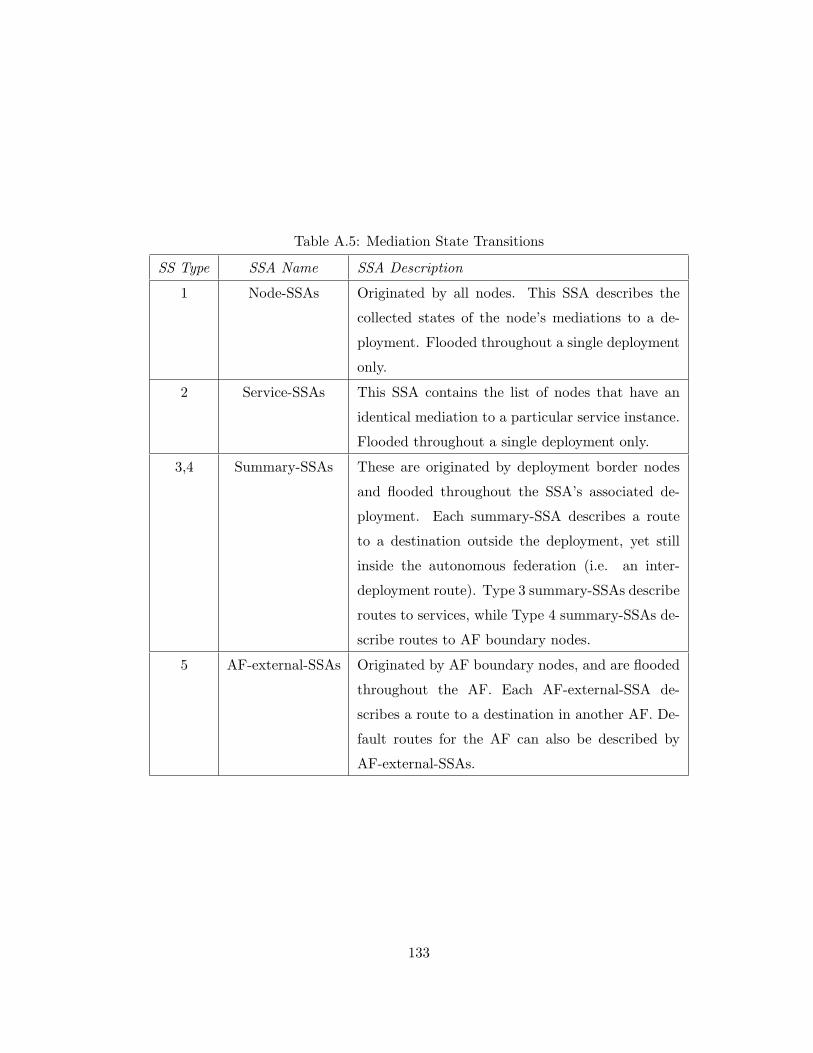
Table A.5: Mediation State Transitions
SS Type SSA Name SSA Description
1 Node-SSAs Originated by all nodes. This SSA describes the
collected states of the node’s mediations to a de-
ployment. Flooded throughout a single deployment
only.
2 Service-SSAs This SSA contains the list of nodes that have an
identical mediation to a particular service instance.
Flooded throughout a single deployment only.
3,4 Summary-SSAs These are originated by deployment border nodes
and flooded throughout the SSA’s associated de-
ployment. Each summary-SSA describes a route
to a destination outside the deployment, yet still
inside the autonomous federation (i.e. an inter-
deployment route). Type 3 summary-SSAs describe
routes to services, while Type 4 summary-SSAs de-
scribe routes to AF boundary nodes.
5 AF-external-SSAs Originated by AF boundary nodes, and are flooded
throughout the AF. Each AF-external-SSA de-
scribes a route to a destination in another AF. De-
fault routes for the AF can also be described by
AF-external-SSAs.
133
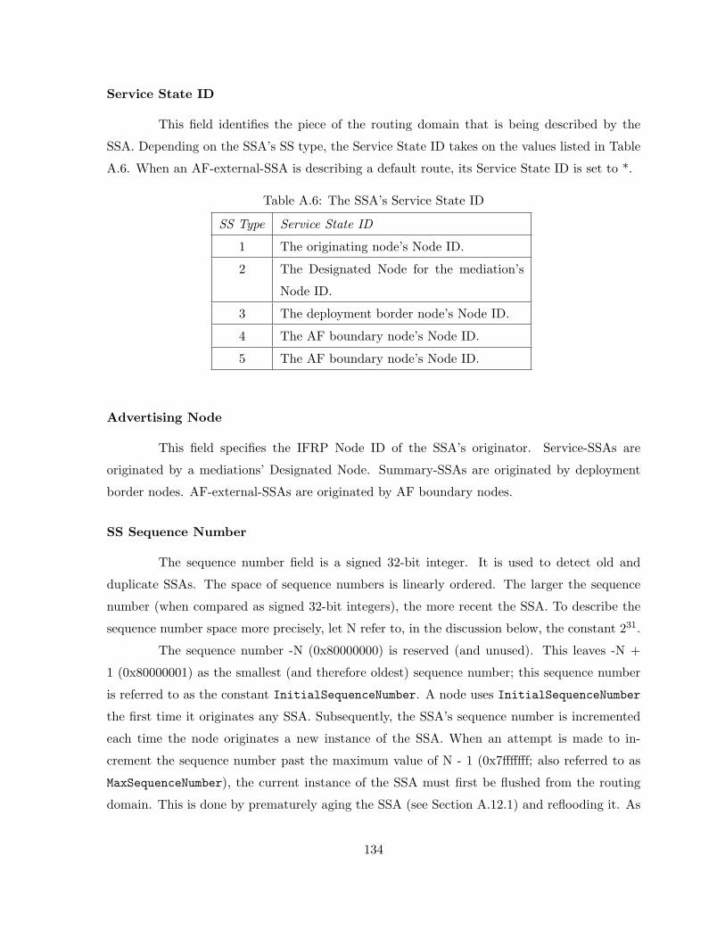
Service State ID
This field identifies the piece of the routing domain that is being described by the
SSA. Depending on the SSA’s SS type, the Service State ID takes on the values listed in Table
A.6. When an AF-external-SSA is describing a default route, its Service State ID is set to *.
Table A.6: The SSA’s Service State ID
SS Type Service State ID
1 The originating node’s Node ID.
2 The Designated Node for the mediation’s
Node ID.
3 The deployment border node’s Node ID.
4 The AF boundary node’s Node ID.
5 The AF boundary node’s Node ID.
Advertising Node
This field specifies the IFRP Node ID of the SSA’s originator. Service-SSAs are
originated by a mediations’ Designated Node. Summary-SSAs are originated by deployment
border nodes. AF-external-SSAs are originated by AF boundary nodes.
SS Sequence Number
The sequence number field is a signed 32-bit integer. It is used to detect old and
duplicate SSAs. The space of sequence numbers is linearly ordered. The larger the sequence
number (when compared as signed 32-bit integers), the more recent the SSA. To describe the
sequence number space more precisely, let N refer to, in the discussion below, the constant 231.
The sequence number -N (0x80000000) is reserved (and unused). This leaves -N +
1 (0x80000001) as the smallest (and therefore oldest) sequence number; this sequence number
is referred to as the constant InitialSequenceNumber. A node uses InitialSequenceNumber
the first time it originates any SSA. Subsequently, the SSA’s sequence number is incremented
each time the node originates a new instance of the SSA. When an attempt is made to in-
crement the sequence number past the maximum value of N - 1 (0x7fffffff; also referred to as
MaxSequenceNumber), the current instance of the SSA must first be flushed from the routing
domain. This is done by prematurely aging the SSA (see Section A.12.1) and reflooding it. As
134
soon as this flood has been acknowledged by all adjacent peers, a new instance can be originated
with sequence number of InitialSequenceNumber.
The node may be forced to promote the sequence number of one of its SSAs when
a more recent instance of the SSA is unexpectedly received during the flooding process. This
should be a rare event. This may indicate that an out-of-date SSA, originated by the node itself
before its last restart/reload, still exists in the Autonomous Federation. For more information
see Section A.11.4.
A.10.2 The Service State Database
A node has a separate service state database for each deployment to which it belongs.
All nodes belonging to the same deployment have identical service state databases for the
deployment.
The databases for each individual deployment are always dealt with separately. Com-
ponents of the deployment service-state database are flooded throughout the deployment only.
Finally, when an adjacency (belonging to Deployment A) is being brought up, only the database
for Deployment A is synchronized between the two nodes.
The deployment database is composed of node-SSAs, service-SSAs and summary-SSAs
(all listed in the deployment data structure). In addition, external routes (AF-external-SSAs)
are included in all non-stub deployment databases (see Section A.2.3).
An implementation of IFRP must be able to access individual pieces of a deployment
database. This lookup function is based on an SSA’s SS type, Service State ID and Advertising
Node. There will be a single instance (the most up-to-date) of each SSA in the database.
The database lookup function is invoked during the SSA flooding procedure (Section A.11). In
addition, using this lookup function the node can determine whether it has itself ever originated
a particular SSA, and, if so, with what SS sequence number.
An SSA is added to a node’s database when either a) it is received during the flooding
process (Section A.11) or b) it is originated by the node itself (Section A.10.3). An SSA is
deleted from a node’s database when either a) it has been overwritten by a newer instance
during the flooding process (Section A.11) or b) the node originates a newer instance of one of
its self-originated SSAs (Section A.10.3) or c) the SSA ages out and is flushed from the routing
domain (Section A.12). Whenever an SSA is deleted from the database, it must also be removed
from all peers’ Service State Retransmission Lists (see Section A.9).
135
A.10.3 Originating SSAs
Into any given IFRP deployment, a node will originate several SSAs. Each node
originates a node-SSA. If the node is also the Designated Node for any of the deployment’s
mediations, it will originate service-SSAs for those mediations.
Deployment border nodes originate a single summary-SSA for each known inter-
deployment destination. AF boundary nodes originate a single AF-external-SSA for each known
AF external destination. Destinations are advertised one at a time so that the change in any sin-
gle route can be flooded without reflooding the entire collection of routes. During the flooding
procedure, many SSAs can be carried by a single Service State Update message.
Whenever a new instance of an SSA is originated, its SS sequence number is incre-
mented, its SS age is set to 0, and the SSA is added to the service state database and flooded
out. See Section A.11.2 for details concerning the installation of the SSA into the service state
database. See Section A.11.3 for details concerning the flooding of newly originated SSAs.
The eight events that can cause a new instance of an SSA to be originated are:
1. The SS age field of one of the node’s self-originated SSAs becomes SSRefreshTime. In
this case, a new instance of the SSA is originated, even though the contents of the SSA
(apart from the SSA header) will be the same. This guarantees periodic originations of
all SSAs. This periodic updating of SSAs adds robustness to the service state algorithm.
SSAs that solely describe unreachable destinations should not be refreshed, but should
instead be flushed from the routing domain (see Section A.12.1).
When whatever is being described by an SSA changes, a new SSA is originated. How-
ever, two instances of the same SSA may not be originated within MinSSInterval. This may
require that the generation of the next instance be delayed by up to MinSSInterval. The
following events may cause the contents of an SSA to change. These events should cause new
originations if and only if the contents of the new SSA would be different:
2. An mediation’s state changes (see Section A.8.1). This may mean that it is necessary to
produce a new instance of the node-SSA.
3. An attached service’s Designated Node changes. A new node-SSA should be originated.
Also, if the node itself is now the Designated Node, a new service-SSA should be produced.
If the node itself is no longer the Designated Node, any service-SSA that it might have
136
originated for the mediation should be flushed from the routing domain (see Section
A.12.1).
4. One of the neighboring nodes changes to/from the Full state. This may mean that it
is necessary to produce a new instance of the node-SSA. Also, if the node itself is the
Designated Node for the mediation, a new service-SSA should be produced.
The next two events concern deployment border nodes only:
5. An intra-deployment route has been added/deleted/modified in the routing table. This
may cause a new instance of a summary-SSA (for this route) to be originated in each
attached deployment.
6. The node becomes newly attached to a deployment. The node must then originate
summary-SSAs into the newly attached deployment for all pertinent intra-deployment
and inter-deployment routes in the nodes’s routing table. See Section A.10.3 for more
details.
The last two events concern AF boundary nodes (and former AF boundary nodes)
only:
7. An external route gained through direct experience with an external routing protocol (like
EFRP) changes. This will cause an AF boundary node to originate a new instance of an
AF-external-SSA.
8. A node ceases to be an AF boundary node, perhaps after restarting. In this situation, the
node should flush all AF-external-SSAs that it had previously originated. These SSAs
can be flushed via the premature aging procedure specified in Section A.12.1.
The construction of each type of SSA is explained in detail below. In general, these
sections describe the contents of the SSA body (i.e., the part coming after the SSA header).
For information concerning the building of the SSA header, see Section A.10.1.
Node-SSAs
A node originates a node-SSA for each deployment that it belongs to. Such an SSA
describes the collected states of the node’s mediations to the deployment. The SSA is flooded
throughout the particular deployment, and no further.
137
The first portion of the SSA consists of the generic SSA header that was discussed in
Section A.10.1. Node-SSAs have SS type = 1.
A node also indicates whether it is a deployment border node or an AF boundary
node by setting the appropriate flags (flag B and flag E, respectively) in its node-SSAs. This
enables paths to those types of node to be saved in the routing table, for later processing of
summary-SSAs and AF-external-SSAs. Flag B should be set whenever the node is actively
attached to two or more deployments. Flag E should never be set in a node-SSA for a stub
deployment (stub deployments cannot contain AF boundary nodes).
The node-SSA then describes the node’s working connections (i.e., mediations) to the
deployment. Each mediation is typed according to the kind of attached service. Each mediation
is also labelled with its Mediation ID. This Mediation ID gives a name to the attached service
endpoint.
Service-SSAs
A service-SSA is generated for each service instance that has more than one node with
a particular mediation. The service-SSA describes all the nodes that provide mediations to a
particular service instance.
The Designated Node for the service originates the SSA. The Designated Node orig-
inates the SSA only if it is fully adjacent to at least one other node on the network. The
service-SSA is flooded throughout the deployment that contains the service instance, and no
further. The service-SSA lists those nodes that are fully adjacent to the Designated Nodes;
each fully adjacent node is identified by its IFRP Node ID. The Designated Node includes itself
in this list.
The Service State ID for a service-SSA is the Mediation ID.
A node that has formerly been the Designated Node for a service, but is no longer,
should flush the service-SSA that it had previously originated. This SSA is no longer used
in the routing table calculation. It is flushed by prematurely incrementing the SSA’s age to
MaxAge and reflooding (see Section A.12.1). In addition, in those rare cases where a node’s
Node ID has changed, any service-SSAs that were originated with the node previous Node ID
must be flushed. Since the node may have no idea what its previous Node ID might have been,
these service-SSAs are indicated by having their Service State ID equal to one of the node’s
mediation IDs and their Advertising Node equal to some value other than the node’s current
Node ID (see Section A.11.4 for more details).
138
Summary-SSAs
The destination described by a summary-SSA is either an mediation, an AF bound-
ary node or a namespace. Summary-SSAs are flooded throughout a single deployment only.
The destination described is one that is external to the deployment, yet still belongs to the
Autonomous Federation.
Summary-SSAs are originated by deployment border nodes. The precise summary
routes to advertise into a deployment are determined in accordance with the algorithm de-
scribed below; both intra-deployment and inter-deployment routes are advertised into the other
deployments.
To determine which routes to advertise into an attached Deployment A, each SSDB
entry is processed as follows:
• Only Destination Types of service and AF boundary node are advertised in summary-
SSAs. If the entry’s Destination Type is deployment border node, examine the next
entry.
• AF external routes are never advertised in summary-SSAs.
• Else, if the deployment associated with this set of paths is the Deployment A itself, do
not generate a summary-SSA for the route.
• Else, if the next hop associated with this set of paths belong to Deployment A itself, do
not generate a summary-SSA for the entry. This is the logical equivalent of a Distance
Vector protocol’s split horizon logic.
• Else, if the SSDB entry indicates that this service or node is unreachable, a summary-SSA
cannot be generated for this route.
• Else, if the destination of this route is an AF boundary node, a summary-SSA should
be originated with Type 4 for the destination, with Service State ID equal to the AF
boundary node’s Node ID. Note: these SSAs should not be generated if Deployment A
has been configured as a stub deployment.
• Else, the Destination type is service. If this is an inter-deployment route, generate a Type
3 summary-SSA for the destination, with Service State ID equal to the deployment border
node’s Node ID.
139
• The one remaining case is an intra-deployment route to a service. This means that the
service instance resides in one of the node’s directly attached deployments. In general,
this information must be condensed before appearing in summary-SSAs. Remember that
a deployment has a configured list of namespaces, each namespace consisting of an URI
and a status indication of either Advertise or DoNotAdvertise. At most, a single Type
3 summary-SSA is originated for each namespace. When the namespace’s status indicates
Advertise, a Type 3 summary-SSA is generated with Service State ID equal to the names-
pace. When the range’s status indicates DoNotAdvertise, the Type 3 summary-SSA is
suppressed and the component services remain hidden from other deployments.
By default, if a service is not contained in any explicitly configured namespace range, a Type
3 summary-SSA is generated with Service State ID equal to the full URI of the mediation
interface.
If a node advertises a summary-SSA for a destination which then becomes unreachable,
the node must then flush the SSA from the routing domain by setting its age to MaxAge and
reflooding (see Section A.12.1). Also, if the destination is still reachable, yet can no longer be
advertised according to the above procedure, the SSA should also be flushed from the routing
domain.
Originating summary-SSAs into stub deployments
The algorithm in Section A.10.3 is optional when Deployment A is an IFRP stub de-
ployment. Deployment border nodes connecting to a stub deployment can originate summary-
SSAs into the deployment according to the Section A.10.3’s algorithm, or can choose to originate
only a subset of the summary-SSAs, possibly under configuration control. The fewer SSAs orig-
inated, the smaller the stub deployment’s service state database, further reducing the demands
on its nodes’ resources. However, omitting SSAs may also lead to sub-optimal inter-deployment
routing, although routing will continue to function.
As specified in Section A.10.3, Type 4 summary-SSAs (AFBR-summary-SSAs) are
never originated into stub deployment.
In a stub deployment, instead of importing external routes each deployment border
node originates a ”default summary-SSA” into the deployment. The Service State ID for the
default summary-SSA is set to DefaultDestination.
140
AF-external-SSAs
AF-external-SSAs describe routes to destinations external to the Autonomous Feder-
ation. Most AF-external-SSAs describe routes to specific external destinations; in these cases,
the SSA’s Service State ID is set to the destination URL. However, a default route for the Au-
tonomous Federation can be described in an AF-external-SSA by setting the SSA’s Service State
ID to DefaultDestination. AF-external-SSAs are originated by AF boundary nodes. An AF
boundary node originates a single AF-external-SSA for each external route that it has learned,
either through another routing protocol (such as BGP), or through configuration information.
AF-external-SSAs are the only type of SSAs that are flooded throughout the entire
Autonomous Federation; all other types of SSAs are specific to a single deployment. However,
AF-external-SSAs are not flooded into/throughout stub deployments (see Section A.2.3). This
enables a reduction in service state database size for nodes internal to stub deployments.
If a node advertises an AF-external-SSA for a destination which then becomes un-
reachable, the node must then flush the SSA from the routing domain by setting its age to
MaxAge and reflooding (see Section A.12.1).
A.11 The Flooding Procedure
Service State Update messages provide the mechanism for flooding SSAs. A Service
State Update message may contain several distinct SSAs, and floods each SSA one hop further
from its point of origination. To make the flooding procedure reliable, each SSA must be
acknowledged separately. Acknowledgments are transmitted in Service State Acknowledgment
messages. Many separate acknowledgments can also be grouped together into a single message.
The flooding procedure starts when a Service State Update message has been received.
Many consistency checks have been made on the received message before being handed to the
flooding procedure (see Section A.7.2). In particular, the Service State Update message has
been associated with a particular peer, and a particular deployment. If the peer is in a lesser
state than Exchange, the message should be dropped without further processing.
All types of SSAs, other than AF-external-SSAs, are associated with a specific de-
ployment. However, SSAs do not contain a deployment field. An SSA’s deployment must be
deduced from the Service State Update message header.
For each SSA contained in a Service State Update message, the following steps are
taken:
141
1. Examine the SSA’s SS type. If the SS type is unknown, discard the SSA and get the next
one from the Service State Update Message. This specification defines SS types 1-5 (see
Section A.3.3).
2. Else, if this is an AF-external-SSA (SS type = 5), and the deployment has been configured
as a stub deployment, discard the SSA and get the next one from the Service State
Update Message. AF-external-SSAs are not flooded into/throughout stub deployments
(see Section A.2.3).
3. Else, if the SSA’s SS age is equal to MaxAge, and there is currently no instance of the
SSA in the node’s service state database, and none of node’s peers are in states Exchange
or Loading, then take the following actions: a) Acknowledge the receipt of the SSA by
sending a Service State Acknowledgment message back to the sending peer (see Section
A.11.5), and b) Discard the SSA and examine the next SSA (if any) listed in the Service
State Update message.
4. Otherwise, find the instance of this SSA that is currently contained in the node’s service
state database. If there is no database copy, or the received SSA is more recent than
the database copy (see Section A.11.1 below for the determination of which SSA is more
recent) the following steps must be performed:
(a) If there is already a database copy, and if the database copy was received via flooding
and installed less than MinSSArrival seconds ago, discard the new SSA (without
acknowledging it) and examine the next SSA (if any) listed in the Service State
Update message.
(b) Otherwise, immediately flood the new SSA out (see Section A.11.3).
(c) Remove the current database copy from all peer’s Service state Retransmission Lists.
(d) Install the new SSA in the service state database (replacing the current database
copy). This may cause a routing table calculation to be scheduled. In addition,
timestamp the new SSA with the current time (i.e., the time it was received). The
flooding procedure cannot overwrite the newly installed SSA until MinSSArrival
seconds have elapsed. The SSA installation process is discussed further in Section
A.11.2.
(e) Possibly acknowledge the receipt of the SSA by sending a Service State Acknowledg-
ment message back out the receiving interface. This is explained below in Section
142
A.11.5.
(f) If this new SSA indicates that it was originated by the receiving node itself (i.e., is
considered a self-originated SSA), the node must take special action, either updating
the SSA or in some cases flushing it from the routing domain. For a description of
how self-originated SSAs are detected and subsequently handled, see Section A.11.4.
5. Else, if there is an instance of the SSA on the sending neighbor’s Service state request
list, an error has occurred in the Database Exchange process. In this case, restart the
Database Exchange process by generating the neighbor event BadSSReq for the sending
neighbor and stop processing the Service State Update message.
6. Else, if the received SSA is the same instance as the database copy (i.e., neither one is
more recent) the following two steps should be performed:
(a) If the SSA is listed in the Service State Retransmission List for the receiving adja-
cency, the node itself is expecting an acknowledgment for this SSA. The node should
treat the received SSA as an acknowledgment by removing the SSA from the Ser-
vice State Retransmission List. This is termed an ”implied acknowledgment”. Its
occurrence should be noted for later use by the acknowledgment process (Section
A.11.5).
(b) Possibly acknowledge the receipt of the SSA by sending a Service State Acknowledg-
ment message back out the receiving interface. This is explained below in Section
A.11.5.
7. Else, the database copy is more recent. If the database copy has SS age equal to MaxAge
and SS sequence number equal to MaxSequenceNumber, simply discard the received SSA
without acknowledging it. (In this case, the SSA’s SS sequence number is wrapping, and
the MaxSequenceNumber SSA must be completely flushed before any new SSA instance
can be introduced). Otherwise, as long as the database copy has not been sent in a
Service State Update within the last MinSSArrival seconds, send the database copy back
to the sending neighbor, encapsulated within a Service State Update message. The Service
State Update message should be sent directly to the neighbor. In so doing, do not put
the database copy of the SSA on the neighbor’s Service State Retransmission List, and
do not acknowledge the received (less recent) SSA instance.
143
A.11.1 Determining which SSA is newer
When a node encounters two instances of an SSA, it must determine which is more
recent. This occurred above when comparing a received SSA to its database copy. This compar-
ison must also be done during the Database Exchange procedure which occurs during adjacency
bring-up.
An SSA is identified by its SS type, Service State ID and Advertising Node. For two
instances of the same SSA, the SS sequence number, and SS age fields are used to determine
which instance is more recent:
• The SSA having the newer SS sequence number is more recent. See Section A.10.1 for
an explanation of the SS sequence number space. If both instances have the same SS
sequence number, then:
– If only one of the instances has its SS age field set to MaxAge, the instance of age
MaxAge is considered to be more recent.
– Else, if the SS age fields of the two instances differ by more than MaxAgeDiff, the
instance having the smaller (younger) SS age is considered to be more recent.
– Else, the two instances are considered to be identical.
A.11.2 Installing SSAs in the database
Installing a new SSA in the database, either as the result of flooding or a newly
self-originated SSA, may cause the resulting routing table structure to be recalculated. The
contents of the new SSA should be compared to the old instance, if present. If there is no
difference, there is no need to recalculate the routing table. When comparing an SSA to its
previous instance, the following are all considered to be differences in contents:
• The SSA’s Options field has changed.
• One of the SSA instances has SS age set to MaxAge, and the other does not.
• The body of the SSA (i.e., anything outside the SSA header) has changed. Note that this
excludes changes in SS Sequence Number.
Also, any old instance of the SSA must be removed from the database when the
new SSA is installed. This old instance must also be removed from all peer’ Service State
Retransmission Lists (see Section A.9).
144

A.11.3 Next Step in the Flooding Procedure
When a new (and more recent) SSA has been received, it must be flooded out to
some set of the node’s peers. This section describes the second part of flooding procedure (the
first part being the processing that occurred in Section A.11), namely, adding the SSA to the
appropriate peers’ Service State Retransmission Lists. Also included in this part of the flooding
procedure is the maintenance of the peers’ Service State Request Lists.
This section is equally applicable to the flooding of an SSA that the node itself has
just originated (see Section A.10.3). For these SSAs, this section provides the entirety of the
flooding procedure (i.e., the processing of Section A.11 is not performed, since, for example,
the SSA has not been received from a peer and therefore does not need to be acknowledged).
Depending upon the SSA’s SS type, the SSA can be flooded out to only certain peers:
AF-external-SSAs (SS Type = 5): AF-external-SSAs are flooded throughout the entire
AF, with the exception of stub deployments (see Section A.2.3). The eligible peers are
all peers, excluding peers who are deployment border nodes in stub deployments.
All other SS types: All other types are specific to a single deployment (Deployment A). The
eligible peers are all other nodes in Deployment A.
Service state databases must remain synchronized over all adjacencies associated with
the eligible peers. This is accomplished by executing the following steps with each eligble peer.
It should be noted that this procedure may decide not to flood an SSA out if there is a high
probability that the attached peers have already received the SSA. However, in these cases the
flooding procedure must be absolutely sure that the peers eventually do receive the SSA, so the
SSA is still added to each adjacency’s Service State Retransmission List. For each eligible peer:
1. If the peer is in a lesser state than Exchange, it does not participate in flooding, and the
next peer should be examined.
2. Else, if the adjacency is not yet full (peer state is Exchange or Loading), examine the
Service State Request List associated with this adjacency. If there is an instance of the
new SSA on the list, it indicates that the peer node has an instance of the SSA already.
Compare the new SSA to the peer’s copy:
(a) If the new SSA is less recent, then examine the next peer.
145
(b) If the two copies are the same instance, then delete the SSA from the Service State
Request List, and examine the next peer.
(c) Else, the new SSA is more recent. Delete the SSA from the Service State Request
List.
(d) If the new SSA was received from this peer, examine the next peer.
(e) At this point, we are not positive that the peer has an up-to-date instance of this new
SSA. Add the new SSA to the Service State Retransmission List for the adjacency.
This ensures that the flooding procedure is reliable; the SSA will be retransmitted
at intervals until an acknowledgment is seen from the peer.
3. The node must now decide whether to flood the new SSA. If, in the previous step, the
SSA was NOT added to any of the Service State Retransmission Lists, there is no need
to flood the SSA out.
4. If the new SSA was received from either the Designated Node or the Backup Designated
Node, chances are that all the peers have received the SSA already. Therefore, continue.
5. If the new SSA was received and the relevant mediation state is Backup (i.e., the node
itself is the Backup Designated Node for this mediation), continue. The Designated Node
will do the flooding. However, if the Designated Node fails the node (i.e., the Backup
Designated Node) will end up retransmitting the updates.
6. If this step is reached, the SSA must be flooded out. Send a Service State Update
message (including the new SSA as contents). The SSA’s SS age must be incremented by
InfTransDelay (which must be > 0) when it is copied into the outgoing Service State
Update message (until the SS age field reaches the maximum value of MaxAge).
A.11.4 Receiving self-originated SSAs
It is a common occurrence for a node to receive self-originated SSAs via the flooding
procedure. A self-originated SSA is detected when either 1) the SSA’s Advertising Node is
equal to the node’s own Node ID or 2) the SSA is a service-SSA and its Service State ID is
equal to one of the node’s mediations.
However, if the received self-originated SSA is newer than the last instance that the
node actually originated, the node must take special action. The reception of such an SSA
146
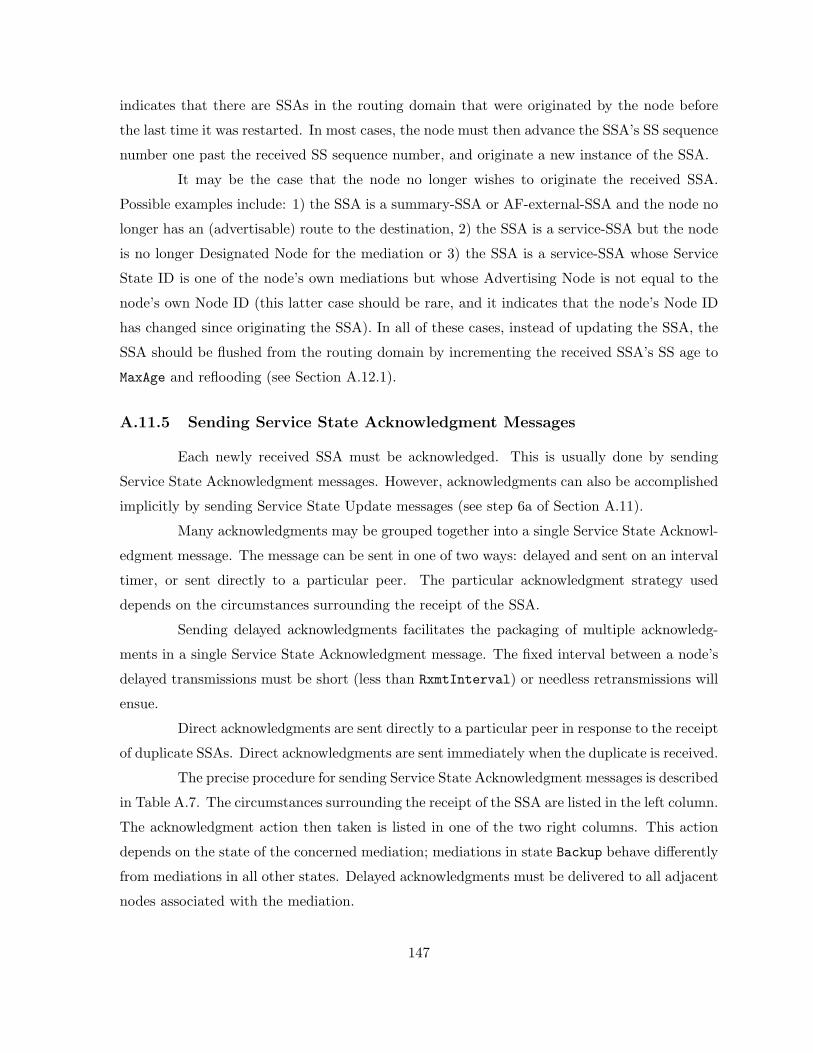
indicates that there are SSAs in the routing domain that were originated by the node before
the last time it was restarted. In most cases, the node must then advance the SSA’s SS sequence
number one past the received SS sequence number, and originate a new instance of the SSA.
It may be the case that the node no longer wishes to originate the received SSA.
Possible examples include: 1) the SSA is a summary-SSA or AF-external-SSA and the node no
longer has an (advertisable) route to the destination, 2) the SSA is a service-SSA but the node
is no longer Designated Node for the mediation or 3) the SSA is a service-SSA whose Service
State ID is one of the node’s own mediations but whose Advertising Node is not equal to the
node’s own Node ID (this latter case should be rare, and it indicates that the node’s Node ID
has changed since originating the SSA). In all of these cases, instead of updating the SSA, the
SSA should be flushed from the routing domain by incrementing the received SSA’s SS age to
MaxAge and reflooding (see Section A.12.1).
A.11.5 Sending Service State Acknowledgment Messages
Each newly received SSA must be acknowledged. This is usually done by sending
Service State Acknowledgment messages. However, acknowledgments can also be accomplished
implicitly by sending Service State Update messages (see step 6a of Section A.11).
Many acknowledgments may be grouped together into a single Service State Acknowl-
edgment message. The message can be sent in one of two ways: delayed and sent on an interval
timer, or sent directly to a particular peer. The particular acknowledgment strategy used
depends on the circumstances surrounding the receipt of the SSA.
Sending delayed acknowledgments facilitates the packaging of multiple acknowledg-
ments in a single Service State Acknowledgment message. The fixed interval between a node’s
delayed transmissions must be short (less than RxmtInterval) or needless retransmissions will
ensue.
Direct acknowledgments are sent directly to a particular peer in response to the receipt
of duplicate SSAs. Direct acknowledgments are sent immediately when the duplicate is received.
The precise procedure for sending Service State Acknowledgment messages is described
in Table A.7. The circumstances surrounding the receipt of the SSA are listed in the left column.
The acknowledgment action then taken is listed in one of the two right columns. This action
depends on the state of the concerned mediation; mediations in state Backup behave differently
from mediations in all other states. Delayed acknowledgments must be delivered to all adjacent
nodes associated with the mediation.
147
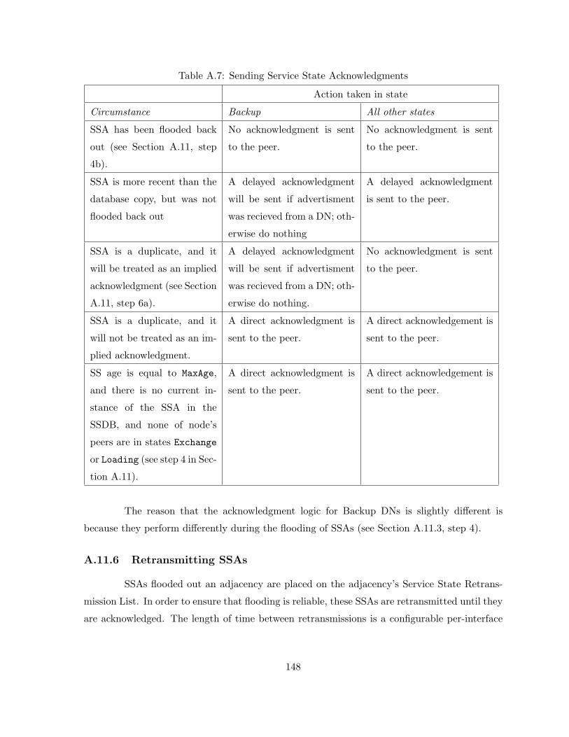
Table A.7: Sending Service State Acknowledgments
Action taken in state
Circumstance Backup All other states
SSA has been flooded back
out (see Section A.11, step
4b).
No acknowledgment is sent
to the peer.
No acknowledgment is sent
to the peer.
SSA is more recent than the
database copy, but was not
flooded back out
A delayed acknowledgment
will be sent if advertisment
was recieved from a DN; oth-
erwise do nothing
A delayed acknowledgment
is sent to the peer.
SSA is a duplicate, and it
will be treated as an implied
acknowledgment (see Section
A.11, step 6a).
A delayed acknowledgment
will be sent if advertisment
was recieved from a DN; oth-
erwise do nothing.
No acknowledgment is sent
to the peer.
SSA is a duplicate, and it
will not be treated as an im-
plied acknowledgment.
A direct acknowledgment is
sent to the peer.
A direct acknowledgement is
sent to the peer.
SS age is equal to MaxAge,
and there is no current in-
stance of the SSA in the
SSDB, and none of node’s
peers are in states Exchange
or Loading (see step 4 in Sec-
tion A.11).
A direct acknowledgment is
sent to the peer.
A direct acknowledgement is
sent to the peer.
The reason that the acknowledgment logic for Backup DNs is slightly different is
because they perform differently during the flooding of SSAs (see Section A.11.3, step 4).
A.11.6 Retransmitting SSAs
SSAs flooded out an adjacency are placed on the adjacency’s Service State Retrans-
mission List. In order to ensure that flooding is reliable, these SSAs are retransmitted until they
are acknowledged. The length of time between retransmissions is a configurable per-interface
148

value, RxmtInterval. If this is set too low, needless retransmissions will ensue. If the value is
set too high, the speed of the flooding, in the face of lost messages, may be affected.
Several retransmitted SSAs may fit into a single Service State Update message.
Service State Update messages carrying retransmissions are always sent directly to the
peer. Each SSA’s SS age must be incremented by InfTransDelay (which must be > 0) when
it is copied into the outgoing Service State Update message (until the SS age field reaches the
maximum value of MaxAge).
If an adjacent node goes down, retransmissions may occur until the adjacency is de-
stroyed by IFRP’s Hello Protocol. When the adjacency is destroyed, the Service State Retrans-
mission List is cleared.
A.11.7 Receiving service state acknowledgments
Many consistency checks have been made on a received Service State Acknowledgment
message before it is handed to the flooding procedure. In particular, it has been associated with
a particular peer. If this peer is in a lesser state than Exchange, the Service State Acknowledg-
ment message is discarded.
Otherwise, for each acknowledgment in the Service State Acknowledgment message,
the following steps are performed:
• Does the SSA acknowledged have an instance on the Service State Retransmission List
for the peer? If not, examine the next acknowledgment. Otherwise:
• If the acknowledgment is for the same instance that is contained on the list, remove the
item from the list and examine the next acknowledgment. Otherwise:
• Log the questionable acknowledgment, and examine the next one.
A.12 Aging the Service State Database
Each SSA has an SS age field. The SS age is expressed in seconds. An SSA’s SS age
field is incremented while it is contained in a node’s database. Also, when copied into a Service
State Update message for flooding out, the SSA’s SS age is incremented by InfTransDelay.
An SSA’s SS age is never incremented past the value MaxAge. SSAs having age MaxAge
are not used in the routing table calculation. As a node ages its service state database, an
SSA’s SS age may reach MaxAge. At this time, the node must attempt to flush the SSA from
149
the routing domain. This is done simply by reflooding the MaxAge SSA just as if it was a newly
originated SSA (see Section A.11.3).
When creating a Database summary list for a newly forming adjacency, any MaxAge
SSAs present in the service state database are added to the neighbor’s Service State Retrans-
mission List instead of the peer’s Database summary list. See Section A.9.3 for more details.
A MaxAge SSA must be removed immediately from the node’s service state database
as soon as both a) it is no longer contained on any peer Service State Retransmission Lists and
b) none of the node’s peers are in states Exchange or Loading.
A.12.1 Premature aging of SSAs
An SSA can be flushed from the routing domain by setting its SS age to MaxAge, while
leaving its SS sequence number alone, and then reflooding the SSA. This procedure follows
the same course as flushing an SSA whose SS age has naturally reached the value MaxAge (see
Section A.12). In particular, the MaxAge SSA is removed from the node’s service state database
as soon as a) it is no longer contained on any peer Service State Retransmission Lists and b)
none of the node’s peers are in states Exchange or Loading. We call the setting of an SSA’s
SS age to MaxAge ”premature aging”.
Premature aging is used when it is time for a self-originated SSA’s sequence num-
ber field to wrap. At this point, the current SSA instance (having SS sequence number
MaxSequenceNumber) must be prematurely aged and flushed from the routing domain before a
new instance with sequence number equal to InitialSequenceNumber can be originated. See
Section A.10.1 for more information.
Premature aging can also be used when, for example, one of the node’s previously
advertised external routes is no longer reachable. In this circumstance, the node can flush its
AF- external-SSA from the routing domain via premature aging. This procedure is preferable
to the alternative, which is to originate a new SSA for the destination specifying a metric of
SSInfinity. Premature aging is also be used when unexpectedly receiving self-originated SSAs
during the flooding procedure (see Section A.11.4).
A node may only prematurely age its own self-originated SSAs. The node may not
prematurely age SSAs that have been originated by other nodes. An SSA is considered self-
originated when either 1) the SSA’s Advertising Node is equal to the node’s own Node ID or 2)
the SSA is a service-SSA and its Service State ID is equal to one of the node’s own mediations.
150