amplifier module model 9243 -...
TRANSCRIPT

Amplifier Module Model 9243
Ad
just
men
t o
f th
eA
mp
lifie
rM
ain
ten
ance
an
dcu
sto
mer
ser
vice
Tec
hn
ical
Dat
aA
pp
end
ixP
rep
arin
g f
or
use
Op
erat
ing
co
ntr
ols
Page 1
Amplifier ModuleModel 9243
© 2007 bursterpräzisionsmesstechnik gmbh & co kgAll rights reservedEdition 28.08.2007
Note:The following information may be amended without prior notice. No part of this document may bereproduced or processed using electronic system without prior consent in writing.
burster provides no warranty of any kind with respect to this material, including the implied warranty ofmerchantable quality and fitness for purpose.burster is not liable under any circumstances for errors, incidental damage or consequential losssustained in connection with the function or use of this material.
Manufacturer:burster präzisionsmesstechnik gmbh & co kgTalstr. 1 - 5 P.O.Box 143276593 Gernsbach 76587 Gernsbach
up to Serial-Nr. 308628

Model 9243 Amplifier ModuleA
dju
stm
ent
of
the
Am
plif
ier
Mai
nte
nan
ce a
nd
cust
om
er s
ervi
ceT
ech
nic
al D
ata
Ap
pen
dix
Pre
par
ing
fo
r u
seO
per
atin
g c
on
tro
ls
Page 2

Amplifier Module Model 9243
Ad
just
men
t o
f th
eA
mp
lifie
rM
ain
ten
ance
an
dcu
sto
mer
ser
vice
Tec
hn
ical
Dat
aA
pp
end
ixP
rep
arin
g f
or
use
Op
erat
ing
co
ntr
ols
Page 3

Model 9243 Amplifier ModuleA
dju
stm
ent
of
the
Am
plif
ier
Mai
nte
nan
ce a
nd
cust
om
er s
ervi
ceT
ech
nic
al D
ata
Ap
pen
dix
Pre
par
ing
fo
r u
seO
per
atin
g c
on
tro
ls
Page 4

Amplifier Module Model 9243
Ad
just
men
t o
f th
eA
mp
lifie
rM
ain
ten
ance
an
dcu
sto
mer
ser
vice
Tec
hn
ical
Dat
aA
pp
end
ixP
rep
arin
g f
or
use
Op
erat
ing
co
ntr
ols
Page 5
1. Preparing for operation1.1 Unpacking the device .........................................................................Page 71.2 Initial commissioning ..........................................................................Page 71.3 Supply voltage ....................................................................................Page 71.4 Terminal assignment ..........................................................................Page 71.5 Grounding and potential binding ........................................................Page 81.6 Installation ..........................................................................................Page 81.7 Storage ............................................................................................Page 8
2. Operating controls2.1 Front panel .........................................................................................Page 92.2 Rear panel ..........................................................................................Page 92.3 Description of the DIP switches .........................................................Page 9
2.3.1 Mounting rail version ...................................................................Page 102.3.2 IP 65 version ...............................................................................Page 11
3. Setting the amplifier3.1 Sensor excitation ................................................................................Page 133.2 Zero point ........................................................................................ Page 133.3 Gain setting ........................................................................................Page 14
3.3.1 Coarse adjustment ......................................................................Page 143.3.2 Fine adjustment ...........................................................................Page 153.3.3 Calculating the gain .....................................................................Page 15
3.4 Input reference point ..........................................................................Page 163.5 Cutoff frequency .................................................................................Page 163.6 Calibration source ..............................................................................Page 163.7 Calibration shunt ................................................................................Page 17
3.7.1 Adjustment and calibration ..........................................................Page 183.7.1.1 Adjustment with a physical variable ...............................Page 183.7.1.2 Adjustment with a high-precision voltage source ...........Page 183.7.1.3 Adjustment with a strain-gauge simulator ......................Page 19
3.8 Courent output ...................................................................................Page 20
4. Maintenance and customer service4.1 Maintenance .......................................................................................Page 214.2 Customer service ...............................................................................Page 21
Contents

Model 9243 Amplifier ModuleA
dju
stm
ent
of
the
Am
plif
ier
Mai
nte
nan
ce a
nd
cust
om
er s
ervi
ceT
ech
nic
al D
ata
Ap
pen
dix
Pre
par
ing
fo
r u
seO
per
atin
g c
on
tro
ls
Page 6
5. Technical specifications5.1 Connectable sensors ......................................................................... Page 23
5.1.1 Strain-gauge ....................................................................... Page 235.1.2 Potentiometer ...................................................................... Page 235.1.3 Transmitter or DC/DC ......................................................... Page 23
5.2 Sensor excitation ............................................................................... Page 235.3 General amplifier data ....................................................................... Page 235.4 Housing ............................................................................................ Page 23
6. Appendix6.1 Sample connections .......................................................................... Page 25
6.1.1 Strain-gauge full-bridge sensors ......................................... Page 256.1.2 Potentiometric sensors ....................................................... Page 256.1.3 DC/DC sensors ................................................................... Page 26
6.2 Diagramm .......................................................................................... Page 276.3 Output of the sensor .......................................................................... Page 286.4 Parallel connection of sensors ......................................................... Page 286.5 Tables for setting amplification stages .............................................. Page 29
6.5.1 Settings for strain-gauge sensors ....................................... Page 296.5.2 Setting for potentiometers and transmitters ........................ Page 31

Amplifier Module Model 9243
Ad
just
men
t o
f th
eA
mp
lifie
rM
ain
ten
ance
an
dcu
sto
mer
ser
vice
Tec
hn
ical
Dat
aA
pp
end
ixP
rep
arin
g f
or
use
Op
erat
ing
co
ntr
ols
Page 7
Terminal Function Description1 Input: + / ~ Supply voltage2 Input: - /~ Supply voltage3 Output: - Ground for the current output4 Output: + Current output5 Output: - Ground for the voltage output6 Output: + *10 V output7 Output: + ±5 V monitor output8 Output: + Calibration voltage 5 mV9 Sensor: - Sensor excitation, shield
10 Sensor: - Sense11 Sensor: + Sensor excitation12 Sensor: + Sense13 Sensor: - Signal input14 Sensor: + Signal input15 Input: Calibration shunt16 Input: Calibration shunt
Table 1: Terminal assignmentFigure 1: Front view of housing
1. Preparing for operation
1.1 Unpacking the deviceCheck the device carefully for signs of damage. If the device seems to have been damaged duringtransport, please notify the supplier within 72 hours. Store the packaging so that it can be examinedby a representative of the supplier and/or manufacturer.
The 9243 must only be transported in its original or an equivalent packaging.
1.2 Initial commissioningOnly connect the device to power supply units which are equipped with a safety transformercomplying with VDE 0551. Transmitters and other components connected in series with the 9243and powered from the mains should also be equipped with a safety transformer complying with VDE0511.
Important! Turn on the operating voltage only once all sensorsand loads have been connected.
1.3 Supply voltageSupply voltage: DC: 20 -36 V unregulated
AC: 14-26 V /45 Hz ... 65 Hz unregulatedThe device can be operated on AC as well as DC without the need for conversion.Power consumption: Approximately 3 VA
1.4 Terminal assignmentIMPORTANT! If possible, please use the 10 V-output (PIN6), even if you only adjust i.e to 0-5 V!If the adjustment is done at burster (order code 9243ABG), this output is always used foradjustment, if not particularly an adjustment on the current output is requested.
Pre
par
ing
fo
r u
se

Model 9243 Amplifier ModuleA
dju
stm
ent
of
the
Am
plif
ier
Mai
nte
nan
ce a
nd
cust
om
er s
ervi
ceT
ech
nic
al D
ata
Ap
pen
dix
Pre
par
ing
fo
r u
seO
per
atin
g c
on
tro
ls
Page 8
1.4.2 Terminal assignment IP 65-version
1 2 3 4 5 6 7 8
9 10 11 12 13 14 15 16
Terminal Function Description1 Input: + / ~ Supply voltage2 Input: - /~ Supply voltage3 Output: - Ground for the current output4 Output: + Current output5 Output: - Ground for the voltage output6 Output: + *10 V output7 Output: + ±5 V monitor output8 Output: + Calibration voltage 5 mV9 Sensor: - Sensor excitation, shield
10 Sensor: - Sense11 Sensor: + Sensor excitation12 Sensor: + Sense13 Sensor: - Signal input14 Sensor: + Signal input15 Input: Calibration shunt16 Input: Calibration shunt
Table 2: Terminal assignment
1.5 Grounding and potential binding
The device is ungrounded. The measurement inputs and outputs are isolated from the supplyvoltage (only applicable to low rated voltages).Observe the potential binding between the sensor, cable shield and downstream-connectedelectronics.
1.6 Installation
On a DIN EN mounting rail.
1.7 Storage
Store the device under dry conditions at a temperature of 0...60°C. The device should not beexposed to moisture. Special measures for commissioning following storage are not required.
Pre
par
ing
fo
r u
se

Amplifier Module Model 9243
Ad
just
men
t o
f th
eA
mp
lifie
rM
ain
ten
ance
an
dcu
sto
mer
ser
vice
Tec
hn
ical
Dat
aA
pp
end
ixP
rep
arin
g f
or
use
Op
erat
ing
co
ntr
ols
Page 9
2. Operating controls
2.1 Front panel
The front panel contains two bores for accessing the potentiometers for fine adjustment of the zeropoint and the gain.
2.2 Rear panel
The rear panel contains two bores for accessing the potentiometers for fine adjustment of thesensor feed voltage and the 5-mV calibration source. The sensor feed voltage only requirescalibration by the customer after it has been switched from the factory default setting (5 V) to adifferent value. In this case, the feed voltage can deviate by up to 0.2% from the setpoint value.
2.3 Description of the DIP switches(see the rear panel 2.2)
DIL switches are located underneath a flap on top of the housing. The device can be parametrizedand configured fully by means of these switches.
The switch settings are described in detail on Page 2.2.
Op
erat
ing
co
ntr
ols

Model 9243 Amplifier ModuleA
dju
stm
ent
of
the
Am
plif
ier
Mai
nte
nan
ce a
nd
cust
om
er s
ervi
ceT
ech
nic
al D
ata
Ap
pen
dix
Pre
par
ing
fo
r u
seO
per
atin
g c
on
tro
ls
Page 10
Op
erat
ing
co
ntr
ols
2.3.1 Mounting rail version
Important ! The switch numbers indicated on the printed circuit board are valid.
S1
2 3 4 5 6 7 8 9 10 11 12 13 14 15 16 17 18 19 20
ON
OFF
View into the amplifier
0-20 mA
4-20 mACurrentoutput
2.5 V
5 V
10 V
Sensorexcitation
10 Hz
1 kHzCutoff frequency
2
4
6
8
Gain factorStage 3 VStage 3
fine
coarseZero point
0.25
0.5
1
2
4
8
16
32
Gain factorStage 2 VStage 2
The signal valences of the switchesare combinable here
1
10
100
Gain factorStage 1 VStage 1
Gai
n V
Tota
l
=
VS
tage
1x
VS
tage
2x
VS
tage
3x
(0.8
5 ...
1.1
1)
Gai
n se
tting
con
trol
er
Exa
mpl
e:13
40
=
10
x
16.7
5x
8
Sen
sor
exci
tatio
n:
5
VC
utof
f fre
quen
cy:
10
Hz
Cur
rent
out
put:
0 -
20
mA
(See
pag
e 3-
3 "F
ine
adju
stm
ent"
)
Exa
mpl
e
Default
(Efficiency of theadjustment
controler "zero")

Amplifier Module Model 9243
Ad
just
men
t o
f th
eA
mp
lifie
rM
ain
ten
ance
an
dcu
sto
mer
ser
vice
Tec
hn
ical
Dat
aA
pp
end
ixP
rep
arin
g f
or
use
Op
erat
ing
co
ntr
ols
Page 11
Bet
rieb
svor
-be
reitu
ng
2.3.2 IP 65 version
Default
View into the IP 65-housing
0-20 mA
4-20 mACurrentoutput
2.5 V
5 V
10 V
Sensorexcitation
10 Hz
1 kHzCutoff frequency
2
4
6
8
Gain factorStage 3
VStage 3
fine
coarseZero point
0.25
0.5
1
2
4
8
16
32
Gain factorStage 2 VStage 2
The signal valences of the switchesare combinable here
1
10
100
Gain factorStage 1 VStage 1
Gai
n V
Tota
l =
VS
tage
1x
VS
tage
2x
VS
tage
3x
(0.8
5 ...
1.1
1)
Gai
n se
tting
con
trol
erE
xam
ple:
1340
=
1
0x
16
.75
x
8
Sen
sor
exci
tatio
n:
5
VC
utof
f fre
quen
cy:
10
Hz
Cur
rent
out
put:
0 -
20
mA
(See
pag
e 3-
3 "F
ine
adju
stm
ent"
)
Exa
mpl
e
(Efficiency of theadjustment
controler "zero")
DIL
ON
OFF1 2 3 4 5 6 7 8 9 10 11 12 13 14 15 16 17 18 19 20
GainPOT32
1
2
3
4
5
6
7
8
9
10
11
12
13
14
15
16
Zero pointPOT31

Model 9243 Amplifier ModuleA
dju
stm
ent
of
the
Am
plif
ier
Mai
nte
nan
ce a
nd
cust
om
er s
ervi
ceT
ech
nic
al D
ata
Ap
pen
dix
Pre
par
ing
fo
r u
seO
per
atin
g c
on
tro
ls
Page 12

Amplifier Module Model 9243
Ad
just
men
t o
f th
eA
mp
lifie
rM
ain
ten
ance
an
dcu
sto
mer
ser
vice
Tec
hn
ical
Dat
aA
pp
end
ixP
rep
arin
g f
or
use
Op
erat
ing
co
ntr
ols
Page 13
Ad
just
men
t o
f th
eA
mp
lifie
r
3. Setting the amplifier
3.1 Sensor excitation
The sensor excitation voltage is asymmetric and referenced to ground. This also allows the shieldof the sensor cable to be connected to the negative sensor feed.
The excitation voltage is supplied via a 4-wire cable. This means that the voltage drops in theexcitation lines can be compensated, provided that appropriate sensors are in use and the probelines are connected. Only use 6-wire extension cables. The excitation lines and probe lines in theplug on a 4-wire sensor are bridged in each case. In the case of a 6-wire sensor, the two sensor linesare generally routed directly to the sensor element, so that bridging is not required.
The following excitation voltages can be set:
2.5 V, 5 V and 10 V
The default excitation voltage of 5 V can be used to operate most sensors. If 2.5 V or 10 V areselected, the device needs to be readjusted. The sensor excitation voltage is short-circuit proof; themaximum current consumption is 35 mA.
3.2 Zero point
The zero point is adjusted with a potentiometer (zero) which can be accessed via a bore in the frontpanel.
The adjustment range of the potentiometers can be set with 2 DIL switches. The switch settings aredescribed in Chapter 2.3 titled 'Description of the DIP switches' (Page 2.2). If both switches are OFF,the adjustment range is smallest. If both switches are ON, the adjustment range is largest. Theswitches can be set in any required combination, so that asymmetric adjustment ranges are alsopossible.
The zero point is adjusted between the second and third amplification stages. If the adjustmentrange is too small, the gain can be decreased in stage 2 and increased in stage 3. If the adustmentrange is too large, the gain can be increased in stage 2 and decreased in stage 3 (refer to the blockdiagram in the appendix ).

Model 9243 Amplifier ModuleA
dju
stm
ent
of
the
Am
plif
ier
Mai
nte
nan
ce a
nd
cust
om
er s
ervi
ceT
ech
nic
al D
ata
Ap
pen
dix
Pre
par
ing
fo
r u
seO
per
atin
g c
on
tro
ls
Page 14
Ad
just
men
t o
f th
eA
mp
lifie
r
3.3 Gain setting
3.3.1 Coarse adjustment
The gain is adjusted coarsely on three amplification stages (stages 1 - 3). DIL switches are assignedto each amplification stage. Multiplying the gain factors set on each stage results in the total coarsegain VTotal (also refer to Page 2.2).
Stage 1 The gain here can be set with DIL switches S1 - S2.110100
Only factors of 1, 10 and 100 are available here. It is not possible to combine these factors, forexample, to obtain 110.
Stage 2 The gain here can be set with DIL switches S3 - S10.0.250.50.751248
16 32
The gain factor here can be adjusted with a resolution of 0.25. The switches can be set in anyrequired combination to obtain, for example, a gain of 33.25.
Stage 3 The gain here can be set with DIL switches S13 - S14.2468
Only factors of 2, 4, 6 and 8 are available here. Combinations are not possible.
The specified gain factors always refer to the 10-V output. The 5-V output and current output arederived from the 10-V output and are available simultaneously. During subsequent fine adjustment,only the output requiring the highest degree of precision is observed. The maximum deviation atthe remaining outputs is then 0.2%.The switch settings are described in detail in Chapter 2.3.
The effective gain factor is approx. 50000. This applies to the following general relationship:UO UI = Input signal
UI = UO = Output signal vTotal VTotal = Gain
This results in a minimum input signal of 0.2 mV for the module amplifier.

Amplifier Module Model 9243
Ad
just
men
t o
f th
eA
mp
lifie
rM
ain
ten
ance
an
dcu
sto
mer
ser
vice
Tec
hn
ical
Dat
aA
pp
end
ixP
rep
arin
g f
or
use
Op
erat
ing
co
ntr
ols
Page 15
Ad
just
men
t o
f th
eA
mp
lifie
r
vTotal = =
3.3.2 Fine adjustment
The gain is adjusted finely with the corresponding control on the front panel.
vTotal = v Stage1 x vStage2 x vStage3 x (0.85 ... 1.11)*
* Fine adjustment
3.3.3 Calculating the gain
When calculating the gain, always use UO = 10 V as the reference, even if the 5-V output isrequired.
Example:
Given: Strain-gauge sensor 350 ohmsRated characteristic value 1.5 mV/VSensor excitation voltage 5 VRequired output voltage UO from the amplifier 10 V
Wanted: Total gain v
The amplifier input voltage UI generated by the sensor is determined as follows:
UI = Rated characteristic value x reference excitation voltage
The relationship
UO 10 V UI 7.5 mV
results in a gain factor v = 1333 in this example. The fine adjustment covers 85 -111% of the gainadjusted coarsely in stages 1 - 3. In this example, the theoretical gain factor therefore liesbetween v = 1133 (85% of 1333) and v = 1480 (111% of 1333).
Calculated total gain: v =1333 (Stage 1 x Stage2 x Stage3)Set total gain: v =1300 (100 x 6.5 x 2)Fine adjustment range: v =1105...1443 (0.85 x1300 to 1.11x1300)

Model 9243 Amplifier ModuleA
dju
stm
ent
of
the
Am
plif
ier
Mai
nte
nan
ce a
nd
cust
om
er s
ervi
ceT
ech
nic
al D
ata
Ap
pen
dix
Pre
par
ing
fo
r u
seO
per
atin
g c
on
tro
ls
Page 16
Ad
just
men
t o
f th
eA
mp
lifie
r
3.4 Input reference point
The signal amplifier acts as a differential amplifier. This means that the negative signal outputis not connected to ground. If a ground connection is required, it must be establishedexternally.
3.5 Cutoff frequency
Using DIL switches, the cutoff frequency can be switched between 10 Hz and 1 Hz (-3dB). Theswitch settings are described in Chapter 2.3 (Page 2.2)
3.6 Calibration source
The 9243 is equipped with a 5.000 mV precision voltage source for the purpose of calibration.This voltage source is referenced to ground and must be connected externally whencalibration is required. Observe the following procedure for this:
1. Disconnect the sensor2. Connect pin 13 with pin 9
Connect pin 14 with pin 93. Adjust "0 V" at the voltage output4. Connect pin 14 with pin 85. adjust the calculated voltage output6. (by large deviation) repeat the points 2 ... 57. connect the sensor8. adjust the zero point
Example
Given: Strain gauge sensor 350 ohmsRated characteristic value 1.5 mV/VSensor excitation voltage 5 VRequired output voltage UO from the amplifier 10 V
Wanted: The amplifier output voltage UOCAL to be set for a calibration excitation voltageUICAL = 5.000 mV
1st step Calculate and set the gain for 1.5 mV/V as described in the example inChapter 3.
When rough changes should be a repetition starting from stepp 2.
Amplifier Module Model 9243
Ad
just
men
t o
f th
eA
mp
lifie
rM
ain
ten
ance
an
dcu
sto
mer
ser
vice
Tec
hn
ical
Dat
aA
pp
end
ixP
rep
arin
g f
or
use
Op
erat
ing
co
ntr
ols
Page 17
Ad
just
men
t o
f th
eA
mp
lifie
r
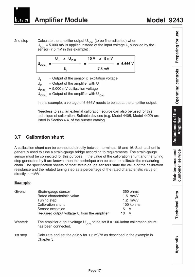
2nd step Calculate the amplifier output UOCAL (to be fine-adjusted) whenUICAL = 5.000 mV is applied instead of the input voltage UI supplied by thesensor (7.5 mV in this example) :
Uo x UICAL 10 V x 5 mVUOCAL = = = 6.666 V
UI 7.5 mV
UI = Output of the sensor x excitation voltageUO = Output of the amplifier with UI
UICAL = 5.000 mV calibration voltageUOCAL = Output of the amplifier with UICAL
In this example, a voltage of 6.666V needs to be set at the amplifier output.
Needless to say, an external calibration source can also be used for thistechnique of calibration. Suitable devices (e.g. Model 4405, Model 4422) arelisted in Section 4.4. of the burster catalog.
3.7 Calibration shunt
A calibration shunt can be connected directly between terminals 15 and 16. Such a shunt isgenerally used to tune a strain-gauge bridge according to requirements. The strain-gaugesensor must be connected for this purpose. If the value of the calibration shunt and the tuningstep generated by it are known, then this technique can be used to calibrate the measuringchain. The specification sheets of most strain-gauge sensors state the value of the calibrationresistance and the related tuning step as a percentage of the rated characteristic value ordirectly in mV/V.
Example
Given: Strain-gauge sensor 350 ohmsRated characteristic value 1.5 mV/VTuning step 1.2 mV/VCalibration shunt 100 kohmsSensor excitation 5 VRequired output voltage UI from the amplifier 10 V
Wanted: The amplifier output voltage UOCAL to be set if a 100-kohm calibration shunthas been connected.
1st step Calculate and set the gain v for 1.5 mV/V as described in the example inChapter 3.

Model 9243 Amplifier ModuleA
dju
stm
ent
of
the
Am
plif
ier
Mai
nte
nan
ce a
nd
cust
om
er s
ervi
ceT
ech
nic
al D
ata
Ap
pen
dix
Pre
par
ing
fo
r u
seO
per
atin
g c
on
tro
ls
Page 18
Ad
just
men
t o
f th
eA
mp
lifie
r
2nd step Calculate the step in the input signal caused by the shunt
UICAL = Tuning step x excitation voltage
In this example: 6.000 mV
3rd step Calculate the amplifier output voltage UOCAL (to be fine-adjusted) whenUICAL (= 6.000 mV in this example) is applied instead of the input voltage UI
supplied by the sensor (7.5 mV in this example) :
Uo x UICAL 10 V x 0.006 VUOCAL = = = 8.000 V
UI 0,0075 V
UI = Output of the sensor x excitation voltageUO = Output of the amplifier with UI
In this example, 8.000 V are to be set at the amplifier output.
The switch settings are described in Chapter 2.3.
3.7.1 Adjustment and calibration
The 9243 can be calibrated using several different techniques. The device settings must bechecked following adjustment.
3.7.1.1 Adjustment with a physical variable
Application: For all sensors.
Function: Using a scale as an example: Adjust the zero point with the scale in the unladenstate. Then load the scale with a known, reference weight and set the final value.
Note: The entire measuring chain is calibrated in this case.
3.7.1.2 Adjustment with a high-precision voltage source (also refer to Chapter3.6)
Application: For all sensors which generate voltages.
Function: The sensor is simulated by a high-precision voltage source. The integratedcalibration source (5.000 mV) or an external source can be used.
Note: In the case of strain-gauge full-bridge sensors and potentiometeric sensors, thefeed voltage influences the measurement results. If you want to verify thefunctionality of the device with voltage sources, you must measure the sensorfeed voltage with a high-precision digital voltmeter and then calculate thecalibration voltage.
This method cannot be used to check whether the sensor functions properly.
Suitable calibration devices (e.g. Model 4405, Model 4422) are listed in Section4.4. of the burster catalog.

Amplifier Module Model 9243
Ad
just
men
t o
f th
eA
mp
lifie
rM
ain
ten
ance
an
dcu
sto
mer
ser
vice
Tec
hn
ical
Dat
aA
pp
end
ixP
rep
arin
g f
or
use
Op
erat
ing
co
ntr
ols
Page 19
Ad
just
men
t o
f th
eA
mp
lifie
r
3.7.1.3 Adjustment with a strain-gauge simulator
In situations where strain-gauge sensors cannot be loaded in accordance with specific parameters,due to an absence of suitable weights, for example, the required measuring signal must be generatedby a strain-gauge simulator. The irregular characteristic values exhibited by many strain-gaugesensors can usually not be set precisely by a simulator. In such cases, the simulator sets the nextlower characteristic value. The corresponding voltage at the amplifier output is calculated as shownin the following example:
Functions and Connection
HD
F
J
KB
M
E
C A
G
L
DMS-Simulator Typ 9405
-+
0
0,51,5
2
3
1
mV/V
+S
-S
+A
-A
+ Excitation
Simulated sensor + output
Simulated sensor - output
- Excitation
Given: A type 8438-100 kN sensor is to be simulated. According to the sensorspecifications, its rated characteristic value is 1.678 mV/V. The required voltage atthe amplifier output for a rated load of 100 kN is UO = 10 V.
Wanted: The amplifier output voltage UOsim to be set after a strain-gauge simulator hasbeen connected.
1st step: Set the strain-gauge simulator to the next lower characteristic value, in this case1.5 mV/V.
2nd step: Calculate the amplifier output voltage to be set if only 1.5 mV/V are supplied by thesimulator instead of 1.678 mV/V by the sensor. Remember:The 1.678 mV/V from the sensor should generate UO=10 V at the amplifier output.
Ua
(Uasim)
Once the strain-gauge simulator has been connected and the characteristic value has been set to1.5 mV/V, set the amplifier output to 8.939 V.
UO x Csim 10 x 1.5 UOsim [V] = = = 8.939
Csens 1.678
U Osim = The voltage at the amplifier output when the simulator is connectedU O = The required amplifier output voltage with the rated sensor loadC sim = The characteristic value set on the strain-gauge simulatorC sens = The characteristic value of the sensor to be simulated
Strain Gauge-SimulatorType 9405
Amplifier ModuleType 9243
Polarity selection(for example for tension -compression simulation)
Output selection

Model 9243 Amplifier ModuleA
dju
stm
ent
of
the
Am
plif
ier
Mai
nte
nan
ce a
nd
cust
om
er s
ervi
ceT
ech
nic
al D
ata
Ap
pen
dix
Pre
par
ing
fo
r u
seO
per
atin
g c
on
tro
ls
Page 20
Ad
just
men
t o
f th
eA
mp
lifie
r
3.8 Current output
Two voltage outputs and one current output are available simultaneously, but only one ofthem can be finely adjusted. The adjustment accuracy of the remaining outputs can deviateby up to 0.2%.
The current outputs are derived from the 10-V voltage output. A range of 0...20 mA or 4...20 mAcan be selected.
There is a mathematical relationship between the current and voltage outputs: 0 V correspondto 0 or 4 mA, while 10 V correspond to 20 mA.
Note that only positive voltages can be converted to equivalent currents. Negativevoltages result in a current of zero.
When calculating the gain and setting the zero point of the device, proceed as though the 10-Vrange needs to be calibrated, but measure the current output by the device. If an ammeter is notavailable, you can alternatively measure the voltage at the 10-V output and then convert it intoa current value.
Calibration and adjustment are performed basically as in the case of the voltage output.
The switch settings are described in Chapter 2.3.

Amplifier Module Model 9243
Ad
just
men
t o
f th
eA
mp
lifie
rM
ain
ten
ance
an
dcu
sto
mer
ser
vice
Tec
hn
ical
Dat
aA
pp
end
ixP
rep
arin
g f
or
use
Op
erat
ing
co
ntr
ols
Page 21
Mai
nte
nan
ce a
nd
cust
om
er s
ervi
ce
4. Maintenance and customer service
4.1 Maintenance
The 9243 does not require any maintenance by the user. Any required repairs must be performedonly by the manufacturer.
4.2 Customer service
Enquiries Please accompany all technical enquiries to the manufacturer with the serialnumber. Only this allow determination of the technical version and promptassistance.
Shipping notesIf the device needs to be send in for repairs, please observe the following asregards its packaging and shipping: Attach a slip of paper to the housing of thedevice outlining the faults exhibited by the device.
If you include your name, department, fax number and telephone number, this willaccelerate the handling of your complaints.
Cleaning Please do not use any cleaning agents containing organic solvents or stronginorganic constituents. A slightly damp cloth is sufficient for this purpose.
Factory warrantyburster präzisionsmesstechnik gmbh & co kg guarantees reliable operation of thedevice for a period of 12 months following delivery.
Any repairs required within this time period will be performed free-of-charge.Damage caused by improper handling of the device is not covered by the termsof the warranty.
Technical specifications are subject to alteration without notice at any time.
Furthermore, we will assume no responsibility whatsoever for consequentialdamage.

Model 9243 Amplifier ModuleA
dju
stm
ent
of
the
Am
plif
ier
Mai
nte
nan
ce a
nd
cust
om
er s
ervi
ceT
ech
nic
al D
ata
Ap
pen
dix
Pre
par
ing
fo
r u
seO
per
atin
g c
on
tro
ls
Page 22

Amplifier Module Model 9243
Ad
just
men
t o
f th
eA
mp
lifie
rM
ain
ten
ance
an
dcu
sto
mer
ser
vice
Tec
hn
ical
Dat
aA
pp
end
ixP
rep
arin
g f
or
use
Op
erat
ing
co
ntr
ols
Page 23
Tec
hn
ical
Dat
a
5. Technical specifications
5.1 Connectable sensors
5.1.1 Strain-gauge
Bridge resistance 350 to 1 kOhmConnection technique 4- and 6-wireCharacteristic value > 0,1mV/V ... 100 mV/VSupple voltage 2,5V, 5V, 10VSupple current 35mA max.
5.1.2 Potentiometer
Track resistance 1kOhm - 5kOhmConnection technique 5-wireMeasurement signal 0 - 5VSupple voltage 5VSupple current 35 mA max.Zero offset wählbar über DIP-Schalter
5.1.3 Transmitter or DC/DC
Measurement signal 2.5 mV - 10VSupple voltage external or 2.5 V / 5V / 10VSupple current 35 mA max.
5.2 Sensor excitation
Voltage 2.5V, 5V, 10V via DIP switchesCurrent 35 mA max.
5.3 General amplifier data
Amplification 1 - 56000 (using DIP switches and a potentiometer)Measurement error 0.05%Temperature coeffizient < 50 ppm / KResidual ripple 5 uVeff or 20 uAeffFrequency range 0 - 10Hz / 0 - 1000Hz (using DIP switches)Potential seperation Input and output on the supply sideAuxiliary power 20 - 36 V DC
14 - 26 V AC 3 V A
5.4 Housing
Protective system IP20Dimensions (WxHxD) 45x75x105Connection Snap-in plug connectors, 2 x 8 terminalsWeight approx. 250gInstallation EN 50022 mounting rail

Model 9243 Amplifier ModuleA
dju
stm
ent
of
the
Am
plif
ier
Mai
nte
nan
ce a
nd
cust
om
er s
ervi
ceT
ech
nic
al D
ata
Ap
pen
dix
Pre
par
ing
fo
r u
seO
per
atin
g c
on
tro
ls
Page 24

Amplifier Module Model 9243
Ad
just
men
t o
f th
eA
mp
lifie
rM
ain
ten
ance
an
dcu
sto
mer
ser
vice
Tec
hn
ical
Dat
aA
pp
end
ixP
rep
arin
g f
or
use
Op
erat
ing
co
ntr
ols
Page 25
Ap
pen
dix
6. Appendix
Sensor Amplifier terminal Description
11 + Excitation
12 + Sense
13 - Output
14 + Output
10 - Sense
9 - Excitation
+U
+F
-
-F
-U
+
6.1 Sample connections
6.1.1 Strain-gauge full-bridge sensors
Figure: Strain-gauge full-bridge
Extension cable:Even in the case of sensors without sense, use a 6-pole cable and bridge thesense lines of the extension cable with the excitation lines in the sensor plug.
Sensor Amplifier terminal Description
11 + Excitation
14 + Output
13 - Output
9 - Excitation, shield
6.1.2 Potentiometric sensors
+U
+UM
Figure: Potentiometric sensors

Model 9243 Amplifier ModuleA
dju
stm
ent
of
the
Am
plif
ier
Mai
nte
nan
ce a
nd
cust
om
er s
ervi
ceT
ech
nic
al D
ata
Ap
pen
dix
Pre
par
ing
fo
r u
seO
per
atin
g c
on
tro
ls
Page 26
Ap
pen
dix
6.1.3 DC/DC sensors
Figure: DC-DC sensors
*) If there is not an electrical connection between exitation and output of the sensorplease realize a bridge between clamp 9 and 13.
Assumption: The sensor is operated on 10 V (other voltages are external).
Sensor Amplifier terminal Description
11 + Excitation
14 + Output
13 - Output
9 - Excitation
+U
UM
-U
DC
DC
*)

Amplifier Module Model 9243
Ad
just
men
t o
f th
eA
mp
lifie
rM
ain
ten
ance
an
dcu
sto
mer
ser
vice
Tec
hn
ical
Dat
aA
pp
end
ixP
rep
arin
g f
or
use
Op
erat
ing
co
ntr
ols
Page 27
Ap
pen
dix
V1
V2
V3
UO
I OU F
U-I
-Wan
dler
Fine
set
ting
cont
rol
"Gai
n"S
tage
3v 3
= 2
/4/6
/8S
ettin
g co
ntro
l"Z
ero"
Sta
ge 2
v 2 =
0,2
5 /0
,5/..
. 32
(Sta
ges)
v max
= 6
3,75
Sta
ge 1
v 1 =
1/1
0/10
0
Shu
nt
+ 5
+ F - F 0
Sen
sor e
xcita
tion
with
sen
se li
nes
2,5/
5/10
VU
ref
Teile
r
5 m
V -
Cal
ibra
tion
sour
ce
+ 15 - 1
5
DC
DC
Sup
ply:
6.2 Block schematic

Model 9243 Amplifier ModuleA
dju
stm
ent
of
the
Am
plif
ier
Mai
nte
nan
ce a
nd
cust
om
er s
ervi
ceT
ech
nic
al D
ata
Ap
pen
dix
Pre
par
ing
fo
r u
seO
per
atin
g c
on
tro
ls
Page 28
6.3 Output of the sensor
An important criterion for determining the gain is the measuring voltage supplied by the sensor inuse. In this respect, the sensor specification format usually varies from one manufacturer toanother.
A strain-gauge full-bridge sensor can have the following specifications, for example:
· Excitation 5 VOutput 2 mV/V
· Sensor excitation 10 VOutput voltage 10 mV
· Reference voltage 5 VSensitivity 2 mV/V
In all 3 examples, the sensor output voltage at full deflection is 10 mV.
6.4 Parallel connection of sensors
For certain weighing applications, it is expedient to operate several strain-gauge full-bridge sensorsconnected in parallel. For this purpose, the feed lines, measuring lines and sensor lines areconnected in parallel in each case. The sensors then act as a single electrical unit.
A prerequisite here is that all sensors should be completely identical in terms of their:
· Characteristic value· Input resistance· Output resistance
If this is not the case, then this technique could give rise to errors. Ensure that the maximumpermissible current is not exceeded.
Voltage Number of 350 Ω sensors
2,5 V 4
5 V 2
10 V 1
Table 6: Parallel-connected sensors
Note: This does not apply to sensors in conjunction with safety barriers.
Ap
pen
dix

Amplifier Module Model 9243
Ad
just
men
t o
f th
eA
mp
lifie
rM
ain
ten
ance
an
dcu
sto
mer
ser
vice
Tec
hn
ical
Dat
aA
pp
end
ixP
rep
arin
g f
or
use
Op
erat
ing
co
ntr
ols
Page 29
Applicable to all output voltage and current ranges
Stage 1 Stage 2 Stage 3Sensor Output Calculated Output Calculated Set Set Set
excitation bridge (reference) gain gain gain gainvoltage (decimal) (0.25...63) (2/4/6/8)
[V] [mV/V] [mV] [V]
2.5 0.1 0.25 10 40.000.00 100 50 8
2.5 0.2 0.5 10 20.000.00 100 50 4
2.5 0.5 1.25 10 8.000.00 100 20 4
2.5 1 2.5 10 4.000.00 100 10 4
2.5 1.25 3.125 10 3.200.00 100 16 2
2.5 1.5 3.75 10 2.666.67 100 13.25 2
2.5 1.75 4.375 10 2.285.71 100 11.5 2
2.5 2 5 10 2.000.00 100 10 2
2.5 2.5 6.25 10 1.600.00 100 8 2
2.5 3 7.5 10 1.333.33 10 66 2
2.5 4 10 10 1.000.00 10 50 2
2.5 5 12.5 10 800.00 10 40 2
2.5 10 25 10 400.00 10 20 2
2.5 15 37.5 10 266.67 10 13.25 2
2.5 20 50 10 200.00 10 10 2
2.5 25 62.5 10 160.00 10 8 2
2.5 30 75 10 133.33 10 6.75 2
2.5 35 87.5 10 114.29 1 57 2
2.5 40 100 10 100.00 1 50 2
2.5 45 112.5 10 88.89 1 44.5 2
2.5 50 125 10 80.00 1 40 2
2.5 60 150 10 66.67 1 33.25 2
2.5 65 162.5 10 61.54 1 30.75 2
2.5 70 175 10 57.14 1 28.5 2
2.5 75 187.5 10 53.33 1 26.75 2
2.5 80 200 10 50.00 1 25 2
2.5 85 212.5 10 47.06 1 23.5 2
2.5 90 225 10 44.44 1 22.25 2
2.5 95 237.5 10 42.11 1 21 2
2.5 100 250 10 40.00 1 20 2
6.5 Tables for setting amplification stages
6.5.1 Settings for strain-gauge sensors
Ap
pen
dix

Model 9243 Amplifier ModuleA
dju
stm
ent
of
the
Am
plif
ier
Mai
nte
nan
ce a
nd
cust
om
er s
ervi
ceT
ech
nic
al D
ata
Ap
pen
dix
Pre
par
ing
fo
r u
seO
per
atin
g c
on
tro
ls
Page 30
Stage 1 Stage 2 Stage 3Sensor Output Calculated Output Calculated Set Set Set
excitation bridge (reference) gain gain gain gainvoltage (decimal) (0.25...63) (2/4/6/8)
[V] [mV/V] [mV] [V]
5 0.1 0.5 10 20.000.00 100 50 4
5 0.2 1 10 10.000.00 100 50 2
5 0.3 1.5 10 6.666.67 100 33.25 2
5 0.4 2 10 5.000.00 100 25 2
5 0.5 2.5 10 4.000.00 100 20 2
5 0.6 3 10 3.333.33 100 16.75 2
5 0.7 3.5 10 2.857.14 100 14.25 2
5 0.8 4 10 2.500.00 100 12.5 2
5 0.9 4.5 10 2.222.22 100 11 2
5 1 5 10 2.000.00 100 10 2
5 1.1 5.5 10 1.818.18 100 9 2
5 1.3 6.25 10 1.600.00 100 8 2
5 1.4 7 10 1.428.57 10 35.75 4
5 1.5 7.5 10 1.333.33 10 33 4
5 1.6 8 10 1.250.00 10 62.5 2
5 1.7 8.5 10 1.176.47 10 58.75 2
5 1.8 8.75 10 1.142.86 10 57 2
5 1.9 9.5 10 1.052.63 10 52.5 2
5 2 10 10 1.000.00 10 50 2
5 2.25 11.25 10 888.89 10 44.5 2
5 2.5 12.5 10 800.00 10 40 2
5 2.75 13.75 10 727.27 10 36.25 2
5 3 15 10 666.67 10 33 2
Stage 1 Stage 2 Stage 3Sensor Output Calculated Output Calculated Set Set Set
excitation bridge (reference) gain gain gain gainvoltage (decimal) (0.25...63) (2/4/6/8)
[V] [mV/V] [mV] [V]
10 0.1 1 10 10.000.00 100 50 2
10 0.2 2 10 5.000.00 100 25 2
10 0.5 5 10 2.000.00 100 10 2
10 1 10 10 1.000.00 100 5 2
10 1.25 12.5 10 800.00 100 4 2
10 1.5 15 10 666.67 10 33.25 2
10 1.75 17.5 10 571.43 10 28.5 2
10 2 20 10 500.00 10 25 2
10 2.5 25 10 400.00 10 20 2
10 3 30 10 333.33 10 16.75 2
Table 3: Gain setting for strain-gauge full-bridge sensors
Ap
pen
dix

Amplifier Module Model 9243
Ad
just
men
t o
f th
eA
mp
lifie
rM
ain
ten
ance
an
dcu
sto
mer
ser
vice
Tec
hn
ical
Dat
aA
pp
end
ixP
rep
arin
g f
or
use
Op
erat
ing
co
ntr
ols
Page 31
Applicable to all output voltage and current ranges
6.5.2 Settings for potentiometers and transmitters
Sensor Meas. Excitation Sensor Internal Calculated Stage 1 Stage 2 Stage 3 Finemodel voltage reference gain adjust-
[V] [V] [V] ment
Potentio. Internal 5 V 5 10 2 1 0.25 8 1.00
Potentio. 50 % Internal 5 V 2.5 10 4 1 0.5 8 1.00
Offset (2.5 V
Offset)
Voltage Internal 1 10 10.00 1 5 2 1.00
or external
Voltage Internal 2 10 5.00 1 2.25 2 1.11
or external
Voltage Internal 3 10 3.33 1 1.5 2 1.11
or external
Voltage Internal 4 10 2.50 1 1.25 2 1.00
or external
Voltage Internal 5 10 2.00 1 1 2 1.00
or external
Voltage Internal 6 10 1.67 1 0.25 6 1.11
or external
Voltage Internal 7 10 1.43 1 0.75 2 0.95
or external
Voltage Internal 8 10 1.25 1 0.75 2 0.8333
or external
Voltage Internal 9 10 1.11 1 0.5 2 1.11
or external
Voltage Internal 10 10 1.00 1 0.5 2 1.00
or external
Table 4: Gain setting for high-level sensors
Ap
pen
dix