amiina bakunowicz:gc pedestrian bridge
TRANSCRIPT

GENERATIVE COMPONENETS: Parametric Modelling
The Brief:
The site for the project is an exist-ing valley in Kazakhstan with the river flowing on its floor. There are three existing levelled plat-forms. Two higher platforms need to be connected to create a bridge and a staircase that leads from th ebridge to the lower level viewing platform.
The following project covers the Centre Line of the main bridge across the valley and the pe-destrian staircase to the viewing platform.
Amiina Bakunowicz1

Amiina Bakunowicz2
GENERATIVE COMPONENETS: Parametric Modelling
GC object
Bridge C/Lpts01,02,03,05
pts08,09direction01direction02direction03
CoordinateSys01
p04 pt07
pt06
Staircase C/L
bsplineCurve03bsplineCurve04
pt25
pt26
pts27,29,31
pt28,30pt32
Method of Construction
from promoted linesfrom promoted lines @ 21m
from pts01,02 @ Z=23mfrom pts03,05 @ Z=23mfrom pts08,09 @ Z=21m
by locating point on the ground @ Z=21m, Xdir towards pt04
by dir02 and distance from pt05by adjusting X & Y of Coordinate-
Sys01byintersection of dir03 and
PlaneXZ of CoordinateSys01
from points along the contour linefrom points along the contour linept along the perpendicular plane to the bridge curve, with origin in the point on that curve at a speci-
fied parameterpoint on bsplineCurve03 at a
specified parameterfixed points on the existing topog-
raphy surface & offset from itpts each side of he mid-plaform
point on bsplineCurve04 at a specified parameter @ Z=6m
pt01@23m
pt01@23m
pt25
pt25
pt26
pt26
pt26pt26pt26
pt27
pt27
pt27
pt28pt29
pts28,29,30
pts28,29,30
pt30
pt32
pt32@6m
pt32pt32pt32
pt31
pt31
pt31
pt02@23m
pt02@23m
bsplineCrv03
bsplineCrv03
bsplineCrv04
bsplineCrv04
pt09@21mpt09@21m
pt09@21m
pt05@21m
Few of the possible variations of the bridge’s Centre Line curve
Few of the possible variations of the staircase’s Centre Line curve. The bottom veiwing platform can extend and shrink depending on the position of pt32 as this point is shared by both the centre line of the staircase and the surface of the view-ing platform
pt05@21m
pt05
pt04@21m
pt04@21m
pt04
pt04@21m
pt06@21m
pt06@21m
pt06@21m
pt06pt25
pt25
pt25
pt01
pt02
pt07@
21m
pt07@21m
pt07
pt03@21m
pt03@21m
pt03
pt08@21m
pt08@21m

Amiina Bakunowicz3
GENERATIVE COMPONENETS: Parametric Modelling
1. Attach an external file with the model of the existing topography on which the bridge and the stair-case will be based on 2. Promote the lines from the attached
model (highlighted in yellow) to the cur-rent GC environment
3. Create bsplineCurve03 and 04 based on the exist-ing topography (refer to the table and diagrams on the page 2)
3. Create pt26 on the bspline-Curve03 by providing its pa-rameter (refer to the table and diagrams on the page 2)
4. Create pts28,29,30 and the mid-platform based on the pa-rameters of the existing topogra-phy (refer to the table and dia-grams on the page 2)
5. Create pt32 and the bottom viewing platform (refer to the ta-ble and diagrams on the page 2)
6. The construction pts of bottom view-ing platform include the two points posi-tioned on the plane perpendicular to the crv04 away from pt32 by half-staircse
7. Create two bsplineCurves from pts25-28 and pts30-32. Divide each by 50 to create 100 steps with 15cm risers (giving total height of 21m-6m = 15m). Connect points on each curve with lines created by Chaining.
8. Each of the new lines will be the parental element to insert a step feature created separately.
9. Each step has a construction line (highlighted in yellow) thet will be served as a parental ele-ment for the new feature Railing.
10. New feature Railing is built from a line that will be poicked up later on from each step and view-ing platforms.
11. Similar construction lines are created on both platforms to receive a new fea-ture Railing.
12. The handrail is created by making a curve from the highest points of the fea-ture Railing. A circular extrusion is then applied giving the resulting steps and platforms with the railings.
Fabrication modelling
Amiina Bakunowicz4
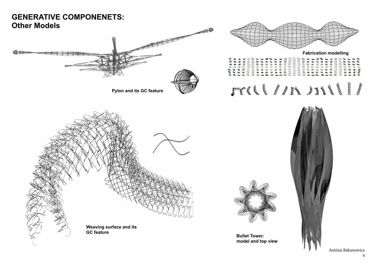
GENERATIVE COMPONENETS:Other Models
Pylon and its GC feature
Bullet Tower: model and top view
Weaving surface and its GC feature