altivar process atv600 handbook - schneider electric document gives you an overview of the available...
TRANSCRIPT

www.schneider-electric.com
Altivar Process
10/2015
English
NH
A3
71
11
.02
ATV660 Compact Drive Systems
Handbook

Altivar ProcessCompact Drive Systems
Low space required in the control room
Generous connecting area for the power cables
Easy accessibility of all components
Control panel for numerous options
Up to at s due to the innovativetandbye y saving60% nerg
" " operationStop & Go without additional costs
Intelligent control of the internal fans depending on the operation
over the whole life cycleOptimal energy efficiency
Logging and graphical presentation of the absorbed power
The energy-saving drive solution
Absorb
ed p
ow
er
Run
Ready
Stop
Energy saving
Reduced consumption by Stop & Go function
Conventional consumption
The customized solution foryour drive
" "Ready-to-use Drive Systems:
Developed on highest quality level
Manufactured according to your needs
Tested at full-load operating conditions
Pre-set appropriate to the design
Compact dimensions
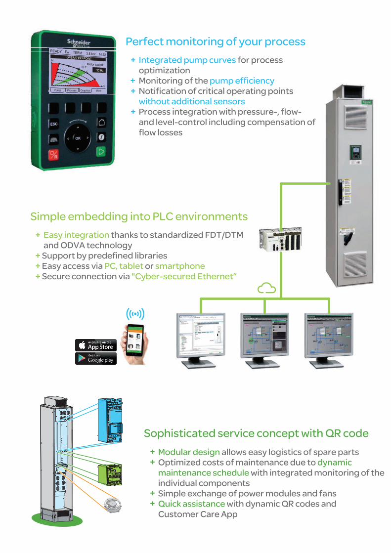
erfe tP c monitoring of your process
Integrated pump curves for process
optimization
Monitoring of the pump efficiency
Notification of critical operating points
without additional sensors
Pro ess integrationc with pressure-, flow-
and level-control including compensation of
flow losses
Easy integration thanks to standardized FDT/DTM
and ODVA technology
Support by predefined libraries
Easy access via orPC, tablet smartphone
Secure connection via "Cyber-secured Ethernet”
Simple into PLC environmentsembedding
allows easy logistics of spare partsModular design
Optimized costs of maintenance due to dynamic
maintenance schedule with integrated monitoring of the
individual components
Simple exchange of power modules and fans
Quick assistance w h c s ait dynamic QR ode nd
Customer Care App
Sophisticated s c c with cervice on ept QR ode

4 NHA37111.02
The information provided in this documentation contains general descriptions and/or technical character-istics of the performance of the products contained herein. This documentation is not intended as a substitute for and is not to be used for determining suitability or reliability of these products for specific user applications. It is the duty of any such user or integrator to perform the appropriate and complete risk analysis, evaluation and testing of the products with respect to the relevant specific application or use thereof. Neither Schneider Electric nor any of its affiliates or subsidiaries shall be responsible or liable for misuse of the information contained herein. If you have any suggestions for improvements or amendments or have found errors in this publication, please notify us.
No part of this document may be reproduced in any form or by any means, electronic or mechanical, including photocopying, without express written permission of Schneider Electric.
All pertinent state, regional, and local safety regulations must be observed when installing and using this product. For reasons of safety and to help ensure compliance with documented system data, only the manufacturer should perform repairs to components.
When devices are used for applications with technical safety requirements, the relevant instructions must be followed.
Failure to use Schneider Electric software or approved software with our hardware products may result in injury, harm, or improper operating results.
Failure to observe this information can result in injury or equipment damage.
© 2015 Schneider Electric. All rights reserved.

NHA37111.02 5
Table of Contents
Safety Information ........................................................................................... 7 About the Book ............................................................................................... 8 Chapter 1 Drive Systems ............................................................................................... 11
Overview ....................................................................................................................................... 12 ATV660 – Compact Drive Systems ............................................................................................... 13 Expandability ................................................................................................................................. 15
Chapter 2 General Specification ................................................................................... 17 Quality ........................................................................................................................................... 18 Mains Conditions .......................................................................................................................... 23 Protection of the Plant ................................................................................................................... 26
Chapter 3 ATV660CQ4X1 ........................................................................................... 31 Description .................................................................................................................................... 32 Specification .................................................................................................................................. 36 Circuit Diagram ............................................................................................................................. 64 Mains Connection ......................................................................................................................... 65 Motor Connection .......................................................................................................................... 68 Customizations ............................................................................................................................. 75
Chapter 4 Wiring of the Control Terminals ................................................................... 77 Design/Position of the Individual Terminals .................................................................................. 78 Control Block ................................................................................................................................. 79 Option "Logic and Analog I/O Card" .............................................................................................. 86 Option "Relay Output Card" .......................................................................................................... 89 Option Terminals ........................................................................................................................... 90
Chapter 5 Customizations ............................................................................................. 93 Enclosure Options ......................................................................................................................... 94 Control Options ............................................................................................................................. 97 I/O Expansion Cards ..................................................................................................................... 98 Communication Cards .................................................................................................................. 99 Functional Safety ........................................................................................................................ 101 Display Options ........................................................................................................................... 102 Motor Options ............................................................................................................................. 103 Mains Supply .............................................................................................................................. 105 Wiring Colors .............................................................................................................................. 109 Monitoring Options ...................................................................................................................... 110 Packaging ................................................................................................................................... 111

6 NHA37111.02

NHA37111.02 7
Safety Information
Important Information
NOTICE
Read these instructions carefully, and look at the equipment to become familiar with the device before trying to install, operate, or maintain it. The following special messages may appear throughout this documentation or on the equipment to warn of potential hazards or to call attention to information that clarifies or simplifies a procedure.
The addition of this symbol to a "Danger" or "Warning" safety label indicates that an electrical hazard exists which will result in personal injury if the instructions are not followed.
This is the safety alert symbol. It is used to alert you to potential personal injury hazards. Obey all safety messages that follow this symbol to avoid possible injury or death.
DANGER DANGER indicates a hazardous situation which, if not avoided, will result in death or serious injury.
WARNING WARNING indicates a hazardous situation which, if not avoided, could result in death or serious injury.
CAUTION CAUTION indicates a hazardous situation which, if not avoided, could result in minor or moderate injury.
NOTICE NOTICE is used to address practices not related to physical injury.
PLEASE NOTE
Electrical equipment should be installed, operated, serviced, and maintained only by qualified personnel. No responsibility is assumed to Schneider Electric for any consequences arising out of the use of this material.
A qualified person is one who has skills and knowledge related to the construction and operation of electrical equipment and its installation, and has received safety training to recognize and avoid the hazards involved.
Qualification Of Personnel
Only appropriately trained persons who are familiar with and understand the contents of this manual and all other pertinent product documentation are authorized to work on and with this product. In addition, these persons must have received safety training to recognize and avoid hazards involved. These persons must have sufficient technical training, knowledge and experience and be able to foresee and detect potential hazards that may be caused by using the product, by changing the settings and by the mechanical, electrical and electronic equipment of the entire system in which the product is used. All persons working on and with the product must be fully familiar with all applicable standards, directives, and accident prevention regulations when performing such work.

8 NHA37111.02
About the Book
At a Glance
Document Scope
This document gives you an overview of the available Altivar Process Drive Systems. Furthermore, you can select from the options described in detail in order to adapt the Altivar Process Drive System to the actual requirements of your system.
Validity Note
is documentation is valid for the Altivar Process Drive Systems.
e technical characteristics of the devices described in this document also appear online. To access this information online:
Step Action 1 o to the Schneider Electric home page www.schneider-electric.com.
2 In the Search box type the reference of a product or the name of a product range. Do not include blank spaces in the reference or product range. To get information on grouping similar modules, use asterisks (*).
3 If you entered a reference, go to the Product Datasheets search results and click on the reference that interests you. If you entered the name of a product range, go to the Product Ranges search results and click on the product range that interests you.
4 If more than one reference appears in the Products search results, click on the reference that interests you.
5 Depending on the size of your screen, you may need to scroll down to see the data sheet.
6 To save or print a data sheet as a .pdf file, click Download XXX product datasheet.
The characteristics that are presented in this manual should be the same as those characteristics that appear online. In line with our policy of constant improvement, we may revise content over time to improve clarity and accuracy. If you see a difference between the manual and online information, use the online information as your reference.

NHA37111.02 9
Related Documents
Use your tablet or your PC to quickly access detailed and comprehensive information on all our products on www.schneider-electric.com.
The internet site provides the information you need for products and solutions:
The whole catalog for detailed characteristics and selection guides The CAD files to help design your installation, available in over 20 different file formats Software and firmware to maintain your drive up to date A large quantity of White Papers, Environment documents, Application solutions, Specifications... to
gain a better understanding of our electrical systems and equipment or automation And finally the User Guides related to your drive, listed below:
Title of Documentation Reference number ATV660 Handbook NHA37110 (German)
Drive Systems – Installation manual NHA37118 (German), NHA37119 (English), NHA37121 (French), NHA37122 (Spanish), NHA37123 (Italian), NHA37124 (Dutch), NHA37126 (Polish), NHA37127 (Portuguese), NHA37128 (Russian), NHA37129 (Turkish), NHA37130 (Chinese)
ATV6 Programming manual EAV64318 (English), EAV64320 (French), EAV64321 (German), EAV64322 (Spanish), EAV64323 (Italian), EAV64324 (Chinese)
ATV6 Modbus serial link manual (embedded) EAV64325 (English)
ATV6 Ethernet manual (embedded) EAV64327 (English)
ATV6 Ethernet IP - Modbus TCP manual (VW3A3720) EAV64328 (English)
ATV6 PROFIBUS DP manual (VW3A3607) EAV64329 (English)
ATV6 DeviceNet manual (VW3A3609) EAV64330 (English)
ATV6 PROFINET manual (VW3A3627) EAV64331 (English)
ATV6 CANopen serial link manual (VW3A3608, 618, 628) EAV64333 (English)
ATV6 Communication parameters EAV64332 (English)
ATV6 Safety function manual EAV64334 (English)
You can download these technical publications and other technical information from our website at www.schneider-electric.com.

10 NHA37111.02

NHA37111.02 11
Chapter 1
Drive Systems
What Is in This Chapter?
This chapter contains the following topics:
Topic Page
Overview 12
ATV660 – Compact Drive Systems 13
Expandability 15

Drive Systems
12 NHA37111.02
Drive Systems
Overview r
Market segment Water and waste water Oil & gas Mining, minerals & metals Food & beverage
Drive Systems Frequency inverter as enclosure unit for speed control of asynchronous and synchronous motors.
Brief description Enclosure unit, alternatively in the standard design, with additional adaptations or as a customized solution
Low Harmonic, alternatively in the standard design, with additional adaptations or as a customized solution
Special features Compact Drive Systems with integrated line reactor to reduce the current harmonics THDi 32...48 %
Low Harmonic Drive Systems with active mains rectifier to reduce the current harmonics THDi < 5 %
Protection degree IP23 standard design of the enclosure IP54 optional design of the enclosure
Power range 110 / 90 up to 800 / 630 kW
Voltage ranges 3AC 380 V -10 % - 415 V +6 % (other voltages possible)
Mains frequency 50/60 Hz +/- 5 %
Output frequency 0.1…500 Hz
Control method Asynchronous motor: Synchronous motor:
Constant load torque standard, variable load torque standard, load-depending mode, energy saving mode PM (permanent magnet) motor
Interfaces Operating panel in the enclosure door, control terminals inside the enclosure, control terminals can be extended, fieldbus connection via Ethernet or Modbus, saving the parameters via USB interface at the keypad
References ATV660 ATV680
Further reading You will find detailed information in this document.
You can find detailed information in the "Altivar Process ATV680 Handbook" and on www.schneider-electric.com.

Drive Systems
NHA37111.02 13
ATV660 – Compact Drive Systems
Frequency inverter as enclosure unit for speed control of asynchronous and synchronous motors. Concept The concept of the ATV660 Compact Drive Systems offers standard enclosures ready to connect. The modular construction makes it possible to adapt the enclosure unit to the individual requests. This economic enclosure variant makes the planning easy and supports a quick installation and commissioning of the drive. Power versus overload For optimum adaptation to the application you can select between two overload models when dimensioning the Altivar Process Drive System. Normal duty
High continuous power with an overload capability of 10 % (typically pumps and fans)
Heavy duty Reduced continuous power but increased overload capability of 50 % for drives with enhanced requirements regarding overload capability, starting torque, load impacts and control performance (typically compressors, mixers, rotary blowers).
Basic equipment The basic equipment contains frequency inverter modules, semiconductor fuses, a main switch, a line reactor to reduce the harmonics, a dv/dt filter choke (from 355 kW) for protection of the motor and spacious mains and motor bars for connection of the power cables. The design is based on the standard enclosure system Spacial SF with an graphical operating panel integrated into the enclosure door. The control is located on a spacious control panel. It provides compact dimensions, nevertheless it is enough space for additional extensions and accessibility in case of maintenance.
Device features
Enclosure system The enclosure system Spacial SF with additional internal reinforcement elements and clearly specified cooling air channel provides optimal cooling of the built-in frequency inverter modules and maximum compactness at the same time. Cooling concept The power part components are cooled in a separate cooling air channel. Via this channel about 90 % of the heat losses are exhausted. The interior of the enclosure is cooled via fans in the enclosure door. At enclosure design IP54 the separated air supply for the power part takes place through the enclosure plinth. Connection The power cables are connected on the mains side and motor side to spaciously dimensioned bars. The strain relief of the cables is realized via an own bar with solid metal clamps. Each device is equipped with an EMC screen bar for correct shield connection. At the standard design, the cables are to be connected at the bottom.

Drive Systems
14 NHA37111.02
Enclosure Design 400 V
ATV660 - General technical data Mains voltage 3 AC 380 V -10 % ... 415 V +6 %, 50/60 Hz ±5 % for TT, TN-C or TN-S
Other voltages and other types of mains possible
Maximum current Normal duty (ND): Heavy duty (HD):
110 % for 60 s per 10 minutes 150 % for 60 s per 10 minutes
Ambient temperature -10...+50 °C (below 0 °C with additional enclosure heating, above +40 °C with derating) You will find further information at chapter "Maximum Ambient Temperature", page 35.
Standard equipment Enclosure system Spacial SF in RAL 7035, protection degree IP23, graphical operating panel in the enclosure door, frequency inverter including main switch, line reactor (32...48 % THDi), mains and motor terminals, cable entry from bottom
Interfaces Pluggable control terminals, fieldbus connection via Ethernet or Modbus
Possible customizations
Increased protection degree IP54 Enclosure plinth for basic device Connection enclosure cable from
top/bottom Enclosure lighting Enclosure heating Key switch "local/remote" Ethernet port on front door Digital and analog I/O card Relay output card Communication cards for various
fieldbus systems STO - SIL 3 Stop category 0 or 1 Front display module (FDM) Modified wiring colors Remote monitoring Seaworthy packaging Differing mains voltages Multipulse supply (12-pulse) Design without main switch Increased short-circuit strength
(100 kA)
Indicator lamps on front door Motor temperature monitoring Bearing temperature monitoring dv/dt filter choke Motor heating Circuit breaker Undervoltage coil for circuit
breaker 230 V Motor for circuit breaker 230 V Automated mains disconnect Safety labels in local language Air intake from back Differing enclosure colors Customized documentation Customized labeling Design for IT mains Motor contactor ...
Standards CE, EAC, ATEX, RFI filter for second "industrial environment" C3 integrated
Type Size Motor rating (ND / HD)
Output current (ND / HD)
Dimensions Width Depth (1) Height
ATV660C11Q4X1 1p
110 kW / 90 kW 211 A / 173 A 400 mm 600 mm 2150 mm ATV660C13Q4X1 132 kW / 110 kW 250 A / 211 A 400 mm 600 mm 2150 mm ATV660C16Q4X1 160 kW / 132 kW 302 A / 250 A 400 mm 600 mm 2150 mm ATV660C20Q4X1
2p 200 kW / 160 kW 370 A / 302 A 600 mm 600 mm 2150 mm
ATV660C25Q4X1 250 kW / 200 kW 477 A / 370 A 600 mm 600 mm 2150 mm ATV660C31Q4X1 315 kW / 250 kW 590 A / 477 A 600 mm 600 mm 2150 mm ATV660C35Q4X1
3p
355 kW / 280 kW 660 A / 520 A 800 mm 600 mm 2150 mm ATV660C40Q4X1 400 kW / 315 kW 730 A / 590 A 800 mm 600 mm 2150 mm ATV660C45Q4X1 450 kW / 355 kW 830 A / 660 A 800 mm 600 mm 2150 mm ATV660C50Q4X1 500 kW / 400 kW 900 A / 730 A 800 mm 600 mm 2150 mm ATV660C56Q4X1
4p 560 kW / 450 kW 1020 A / 830 A 1200 mm 600 mm 2150 mm
ATV660C63Q4X1 630 kW / 500 kW 1140 A / 900 A 1200 mm 600 mm 2150 mm ATV660C71Q4X1
5p 710 kW / 560 kW 1260 A / 1020 A 1400 mm 600 mm 2150 mm
ATV660C80Q4X1 800 kW / 630 kW 1420 A / 1140 A 1400 mm 600 mm 2150 mm (1) Total depth including door handle and switch handle: 664 mm

Drive Systems
NHA37111.02 15
Expandability
The new Altivar Process Drive Systems are the result of our many years of experience in the field of electronic drives. Moreover we provide especially designed expansion options for a various range of applications. Our worldwide, certified manufacturing sites and the local engineering teams allow a global offer.
Predefined Customizations
Due to the predefined customizations the Altivar Process Drive System can be adapted easily and quick to the customer requirements. Besides, this allows minimal delivery time for an individually adapted enclosure ready to connect. Certainly the Altivar Process Drive Systems can be ordered also in the basic design, which is already extensive equipped, without any customization. Predefined customizations are: Increased protection degree IP54 Enclosure plinth for basic device Connection enclosure cable from top/bottom Enclosure lighting Enclosure heating Key switch "local/remote" Ethernet port on front door Digital and analog I/O card Relay output card Communication cards for various fieldbus
systems STO - SIL 3 Stop category 0 or 1 Front display module (FDM) Indicator lamps on front door Motor temperature monitoring Bearing temperature monitoring dv/dt filter choke Motor heating Circuit breaker Undervoltage coil for circuit breaker Motor for circuit breaker
Automated mains disconnect Safety labels in local language Modified wiring colors Remote monitoring Seaworthy packaging Differing mains voltages Multipulse supply (12-pulse) Design without main switch Increased short-circuit strength (100 kA) Air intake from back Differing enclosure colors Customized documentation Customized labeling Design for IT mains Motor contactor Integrated control functions ...
Individual Customizations
Due to our substantial know-how and the high flexibility in performing projects, it is possible to realize unique system solutions. They are individually adapted to the customers demands. Typical customizations: Multi drives (several frequency inverters in an enclosure composition) Differing cooling system Different enclosure system Differing dimensions ...

Drive Systems
16 NHA37111.02
Type designation
The type designation of the Altivar Process Drive Systems consists of several points of signs (characters and figures). The meaning of each point is illustrated in the following example.
ATV 660 C16 Q4 X1
Product Description ATV Altivar Segments 660 Compact Drive Systems Drive power C11…C80 110 / 90 kW … 800 / 630 kW Mains voltage Q4 3 AC 380 V -10 % ... 415 V +6 % Design variant X1 Europe CE
NHA37111.02 17
Chapter 2
General Specification
What Is in This Chapter?
This chapter contains the following topics:
Topic Page
Quality 18
Mains Conditions 23
Protection of the Plant 26
General Specification
18 NHA37111.02
Gener al Specificati on
Quality
Altivar frequency inverters use modern components and solutions for the control of asynchronous three-phase motors and synchronous three-phase motors. This enables an extremely compact design and user-friendly device features.
Our high degree of quality awareness ranges from the basic requests in the product specification over the development of the cooling system, of the mechanical design, of the electrical circuit diagram and the individual functions up to the production of the device. This process quality level is also long-term guaranteed by means of the corresponding quality assurance systems in the individual business processes and is certified every year by independent authorities according to DIN EN ISO 9001.
The Altivar Process Drive Systems fulfil the relevant international standards and regulations.
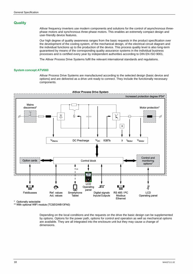
System concept ATV660
Altivar Process Drive Systems are manufactured according to the selected design (basic device and options) and are delivered as a drive unit ready to connect. They include the functionally necessary components.
Depending on the local conditions and the requests on the drive the basic design can be supplemented by options. Options for the power path, options for control and operation as well as mechanical options are available. They are all integrated into the enclosure unit but they may cause a change of dimensions.

General Specification
NHA37111.02 19
CE Marking
The frequency inverters have a CE marking on the rating plate. However, to achieve the corresponding limits it is necessary to observe the installation regulations, superior and regional standards and directives as well as the directives listed below.
All devices and drives of the electric drive engineering may cause electromagnetic interferences and otherwise they may be influenced by such interferences. Therefore, they are subject to the EMC directive 2004/108/EC.
The frequency inverters have an operating voltage which is clearly in the range of 50...1000 V AC or 75...1500 V DC. Therefore, they are also subject to the Low Voltage Directive 2006/95/EC.
Because of the EMC filters which are built into the frequency inverters they are in conformity with EN 61800-3 and EN 61800-5-1.
Frequency inverters are not considered as stand-alone machines according to the Machinery Directive 2006/42/EC. They have to be accounted as component of the closed functional safety system.
NOTICE INSUFFICIENT SAFETY CALCULATION Frequency inverters have to be included in the whole safety calculation of machinery by the equipment manufacturer. Failure to follow these instructions can result in equipment damage.
Frequency inverters are a product of the restricted sales according to IEC 61800-3. In a residential environment this product can cause radio frequency interferences.
NOTICE RISK OF RADIO FREQUENCY INTERFERENCES If radio frequency interferences occur in a residential environment because of the operation of the frequency inverter, the user can be called on to take suitable measures. Failure to follow these instructions can result in equipment damage.
Installation Regulations
The frequency inverters have a RFI filter for grounded mains built-in. Take care of good HF connection between motor cable screen and filter. Use of shielded motor cables, proper connection of the motor cables on both ends or proper laying in
a metallic, closed and interconnected cable conduit In case of high motor cable lengths a corresponding dv/dt filter choke is required. Use shielded control cables and connect them correctly. Ground the frequency inverter for human protection. Consider the protective separation (PELV) when preparing signal wires and coupling relays. Lay the motor cables separate from other cables, especially from the signal wires.
NOTE: Further information is given in the installation manual.

General Specification
20 NHA37111.02
Safety of Machinery
For the functional safety and stop categories the function "Safe Torque Off (STO)" has been integrated. So an optimal adaptation of the drive to the required safety category for the machine is possible.
NOTE: You will find further information about this function in chapter "Safe Torque Off (STO)", page 101.
For all selectable safety options the implementation of external safety-relevant contacts is provided. So the Altivar Process does not act as a closed functional safety system in terms of the Machine directive and safety standards EN/IEC 61508, ISO 13849-1 and NF EN 62061. It has to be accounted as component in any case.
NOTICE INSUFFICIENT SAFETY CALCULATION The safety-relevant components which are installed in the Altivar Process and their safety-relevant functionality have to be included in the whole safety of machinery by the equipment manufacturer. Failure to follow these instructions can result in equipment damage.
General Specification
NHA37111.02 21
EMC Product Standard for PDS (Power Drive Systems) EN 61800-3
For frequency inverter drives the product standard EN/IEC 61800-3 edition 1 and 2 appeared. It has first priority over the existing general standards (generic standards). If a drive is installed into another device for which a separate EMC product standard exists, then this standard applies.
The aim of the EMC directive 2004/108/EEC is the ability of electric and electronic installations to operate satisfactorily in their electromagnetic environment without influencing the environment or other loads therein.
Therefore, the PDS product standard contains both limits for admissible interferences and requirements for the necessary interference resistance.
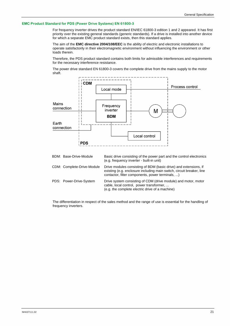
The power drive standard EN 61800-3 covers the complete drive from the mains supply to the motor shaft.
BDM: Base-Drive-Module Basic drive consisting of the power part and the control electronics (e.g. frequency inverter - built-in unit)
CDM: Complete-Drive-Module Drive modules consisting of BDM (basic drive) and extensions, if existing (e.g. enclosure including main switch, circuit breaker, line contactor, filter components, power terminals, ...)
PDS: Power-Drive-System Drive system consisting of CDM (drive module) and motor, motor cable, local control, power transformer, ... (e.g. the complete electric drive of a machine)
The differentiation in respect of the sales method and the range of use is essential for the handling of frequency inverters.
General Specification
22 NHA37111.02
Use In Industrial Environment
The standard refers to these application areas as "second environment". These are areas which are separated from the public mains by means of an own transformer.
The user has to take care that the suppression components recommended by the manufacturer are used and that the introductions of the manufacturer are observed. Moreover, the user has to take care that strong interferences do not couple into neighboring low-voltage mains.
If the neighboring mains is a public mains with residential areas, the limits 66-56/56/60 dB(μV) quasi-peak apply. In case of industrial mains the higher limits 79/73/73 dB(μV) quasi-peak can be used.
Furthermore, it is necessary to enhance the suppression of interferences if other devices are influenced. The operator of the plant is responsible for this improvement.
The limits for immunity are much stricter because they are based on a generally higher level of interferences.
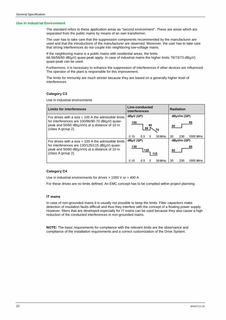
Category C3
Use in industrial environments
Limits for interferences Line-conducted interferences Radiation
For drives with a size ≤ 100 A the admissible limits for interferences are 100/86/90-70 dB(μV) quasi-peak and 50/60 dB(μV/m) at a distance of 10 m (class A group 2).
For drives with a size > 100 A the admissible limits for interferences are 130/125/115 dB(μV) quasi-peak and 50/60 dB(μV/m) at a distance of 10 m (class A group 2).
Category C4
Use in industrial environments for drives > 1000 V or > 400 A
For these drives are no limits defined. An EMC concept has to be compiled within project planning.
IT mains
In case of non-grounded mains it is usually not possible to keep the limits. Filter capacitors make detection of insulation faults difficult and thus they interfere with the concept of a floating power supply. However, filters that are developed especially for IT mains can be used because they also cause a high reduction of the conducted interferences in non-grounded mains.
NOTE: The basic requirements for compliance with the relevant limits are the observance and compliance of the installation requirements and a correct customization of the Drive System.
General Specification
NHA37111.02 23
Mains Conditions
Mains Voltage
The Altivar Process Drive Systems are designed for standard industrial mains TT and TN with following mains voltage:
Rated voltage Un: 3 AC 380 V -10 % ... 415 V +6 %, 50/60 Hz ±5 %
NOTE: Other voltages and the use in IT mains or "Corner grounded networks" are available on request.
The mains voltage must comply with the requirements according to IEC 60038 and EN 50160: Unbalance between phases: < 2 % Total harmonic factor THD(v): < 10 % Maximum single harmonic: < 5 %
CAUTION INCOMPATIBLE LINE VOLTAGE Ensure that the line voltage corresponds with the supply voltage of the frequency inverter before you switch the inverter on to configure it. An incompatible line voltage may cause damage of the inverter. Failure to follow these instructions can result in injury or equipment damage.
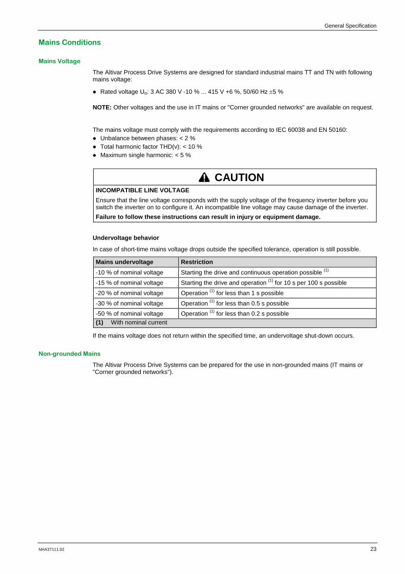
Undervoltage behavior
In case of short-time mains voltage drops outside the specified tolerance, operation is still possible.
Mains undervoltage Restriction -10 % of nominal voltage Starting the drive and continuous operation possible (1)
-15 % of nominal voltage Starting the drive and operation (1) for 10 s per 100 s possible
-20 % of nominal voltage Operation (1) for less than 1 s possible
-30 % of nominal voltage Operation (1) for less than 0.5 s possible
-50 % of nominal voltage Operation (1) for less than 0.2 s possible (1) With nominal current
If the mains voltage does not return within the specified time, an undervoltage shut-down occurs.
Non-grounded Mains
The Altivar Process Drive Systems can be prepared for the use in non-grounded mains (IT mains or "Corner grounded networks").

General Specification
24 NHA37111.02
Radio Interferences
The Altivar Process Drive Systems include a radio frequency interference filter as standard. This filter fulfils the requirements for category "C3 – industrial environments" according to EN/IEC 61800-3 (in the past: EN 55011 class A group 2).
Frequency inverters are a product of the restricted sales according to IEC 61800-3. In a residential environment this product can cause radio frequency interferences.
NOTICE RISK OF RADIO FREQUENCY INTERFERENCES If radio frequency interferences occur in a residential environment because of the operation of the frequency inverter, the user can be called on to take suitable measures. Failure to follow these instructions can result in equipment damage.
Mains Impedance / Short-circuit Current
The Altivar Process Drive Systems are designed considering a maximal and minimal permitted mains short-circuit current of the supply (values see "Technical data" of the respective frequency inverter).
These frequency inverters can be designed for higher mains short-circuit currents on request. You will find information about the short-circuit protection at chapter "Mains Connection ", page 65.
Reactive Current Compensation Systems
Frequency inverters cause harmonics in the supplying mains (see page page 67). When a reactive current compensation system is used, their capacitors are additionally stressed by means of the harmonics.
NOTICE RISK OF OVERLOAD OF THE REACTIVE CURRENT COMPENSATION SYSTEM We recommend the installation of chokes for the compensation system, which helps to protect the reactive current compensation system against overload or resonances. Failure to follow these instructions can result in equipment damage.
12-/24-pulse Supply
All Altivar Process Drive Systems can be designed with 12-pulse supply. For some types also the design with 24-pulse supply is possible.
NOTE: You will find information about the design variations from page 107.

General Specification
NHA37111.02 25
Switching Rate
Altivar Process Drive Systems are equipped with a main switch for disconnecting the applied mains voltage.
In case of frequent start/stop requests it is recommended to realize them by means of the digital control inputs (or via a serial bus) directly to the electronics of the inverter.
Optionally the mains separation can be realized by a circuit breaker with motor.
NOTE: By means of the certificated control inputs STOA_____
and STOB_____
a "Safe Torque Off" of the drive is considering the safety category according to ISO 13849-1 (and IEC/EN 61800-5-2). Disconnecting the mains supply or the motor is therefore not required.
Inverter control Switching rate ATV660 Mains voltage switched external Max. 60 switching operations per hour
Mains voltage switched internal: Main switch (standard) Circuit breaker (option) Circuit breaker with motor (option)
Max. 10 switching operations per hour Max. 10,000 switching operations total
Start / Stop requests via digital inputs with active energy saving function "Stop and Go" (1)
Max. 60 switching operations per hour
Start / Stop requests via digital inputs without energy saving function "Stop and Go" (1)
Arbitrary
Release / Lock via STO inputs with active energy saving function "Stop and Go" (1)
Max. 60 switching operations per hour
Release / Lock via STO inputs without energy saving function "Stop and Go" (1)
Arbitrary
Mains voltage switched external via contactor (on request) Max. 60 switching operations per hour
(1) The energy saving function "Stop and Go" is activated by default.
NOTE: The device fans are automatically controlled depending on the start/stop request.

General Specification
26 NHA37111.02
Protection of the Plant
Responsibility
All stated connection recommendations and planning remarks are to be taken merely as suggestions which must be adapted to the local conditions and regulations concerning installation and usage.
This applies especially to the functional safety regulations for machines, the EMC regulations and the general regulations for human protection.
WARNING HUMAN PROTECTION AND SAFETY OF MACHINERY Integrate the frequency inverter into the protection and safety concept of the plant or machine. Failure to follow these instructions can result in death, serious injury or equipment damage.
Installation Site
Altivar Process Drive Systems are qualified for vertical installation in electrical operating rooms as well as in the area of production facilities.
Air inflow temperature: -10...+50 °C
(below 0 °C with additional enclosure heating, above +40 °C with derating)
CAUTION REDUCED AVAILABILITY AND LIFE-TIME Install the Altivar Process Drive System on a solid, vibration-free ground. Fix the Altivar Process Drive System in the final position. Take care that the air exchange is sufficient for dissipation of the lost heat. Avoid environmental effects like high temperatures and high humidity as well as dust, dirt and
corrosive gases. Prevent condensation inside the Altivar Process Drive System. Read and follow the information which is given in the installation manual. Failure to follow these instructions can result in injury or equipment damage.
NOTE: At enclosure design IP54 the ATV660 frequency inverter is qualified for pollution degree 3 according to EN 61800-5-1.
NOTE: Further information is given in the installation manual.

General Specification
NHA37111.02 27
Increased Motor Speed
With the Altivar Process Drive Systems it is possible to control the rotational speed of motors from 0.1...500 Hz.
CAUTION OPERATION OF MOTORS WITH INCREASED SPEED Check whether all used components are qualified for operation at frequencies higher than 60 Hz. Ask the manufacturer of the motor and the machine if necessary. Failure to follow these instructions can result in injury or equipment damage.
Overvoltage Protective Circuit
Provide a free-wheeling diode for DC control circuits.
For AC control circuits the R/C wiring is preferable compared to a wiring with varistors because as a result not only the peak overvoltage is reduced but also the rise-time.
CAUTION RISK OF MALFUNCTIONS IN THE CONTROL CIRCUITS Ensure that all inductances like relays, contactors, magnetic brakes, etc. are equipped with an
overvoltage protective circuit. It helps to prevent malfunctions of the conventional device control as well as of the fieldbus.
Use a protective circuit which is qualified for inverter operation. Failure to follow these instructions can result in injury or equipment damage.
Residual Current Circuit Breaker
Frequency inverters, especially those with additional EMC filters and shielded motor cables, lead an increased leakage current against ground.
The leakage current depends on:
• The length of the motor cable • The type of laying and whether the motor cable is shielded or not • The set pulse frequency • The use of an additional radio frequency interference filter • The grounding of the motor at its installation place (grounded or non-grounded)
Depending on the conditions, the leakage current of plants with high cable lengths can be absolutely higher than 100 mA !
The built-in residual current detection has no current-limiting effect. It only helps to protect the drive and is no human protection.
Particularly because of the capacitors of the radio frequency interference filter, an unintentional triggering of a residual current circuit breaker may occur at the moment of switching on. As well, the ground capacitances may cause an incorrect triggering during operation. On the other hand, it is possible that the triggering is blocked by means of DC components which are caused by the mains rectification at the input of the inverter.
CAUTION INCORRECT TRIGGERING OF THE RESIDUAL CURRENT CIRCUIT BREAKER Use only short-time delayed and pulse current sensitive residual current circuit breakers with
considerably higher tripping current. Protect the other loads by means of a separate residual current circuit breaker. Residual current circuit breakers in front of an inverter do not provide absolutely reliable protection
in case of direct contact !! So they should be always used in combination with other protective measures.
The frequency inverters have no current-limiting effect (in case of residual currents) and therefore they do not violate the protective multiple grounding..
Failure to follow these instructions can result in injury or equipment damage.
General Specification
28 NHA37111.02
Automatic Restarting
This function increases the availability, especially for drives that are not integrated into the plant control via a fieldbus system. Depending on the parameterization, the frequency inverter can automatically start-up again after each mains switch-on or mains recurrence.
DANGER UNINTENDED EQUIPMENT OPERATION Make sure that there is no risk for persons or equipment in case of an automatic restart. Failure to follow these instructions will result in death or serious injury.
Locking of the Frequency Inverter
Altivar Process Drive Systems include the standard protective function "Safe Torque Off (STO)", which helps to prevent any unintended start-up of the motor. This function fulfills, when correctly wired, the machine standard ISO 13849-1 Performance level PL e, the IEC/EN 61508 Safety integrity level SIL 3 standard for functional safety and the power drive system standard IEC/EN 61800-5-2.
NOTE: You will find further information in the Safety Function Manual (EAV64334).
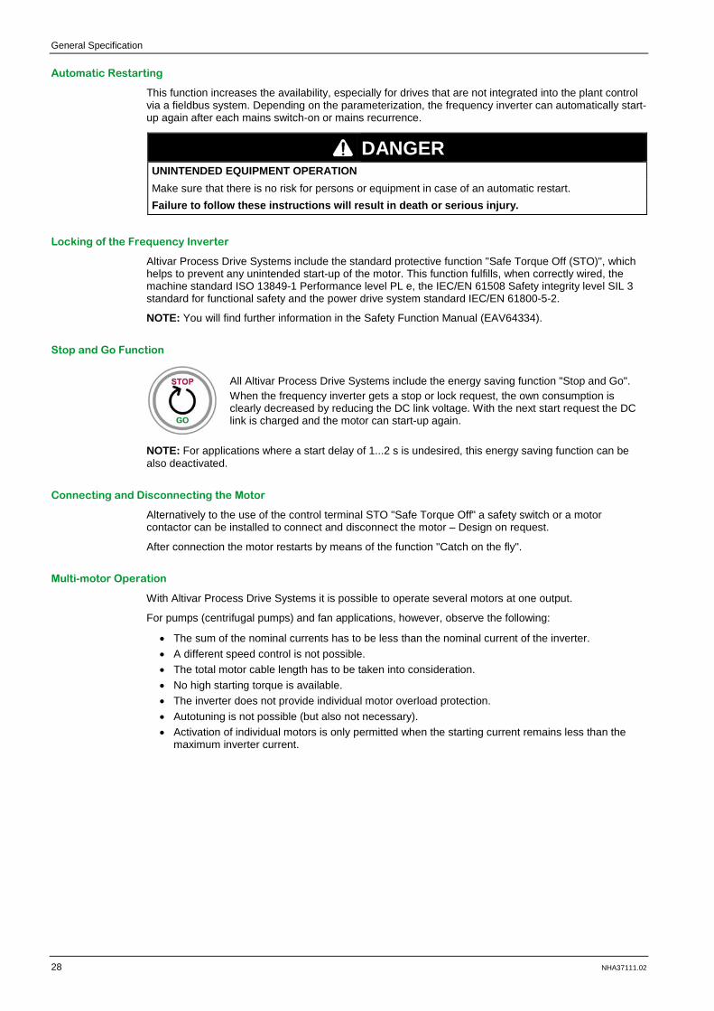
Stop and Go Function
All Altivar Process Drive Systems include the energy saving function "Stop and Go". When the frequency inverter gets a stop or lock request, the own consumption is clearly decreased by reducing the DC link voltage. With the next start request the DC link is charged and the motor can start-up again.
NOTE: For applications where a start delay of 1...2 s is undesired, this energy saving function can be also deactivated.
Connecting and Disconnecting the Motor
Alternatively to the use of the control terminal STO "Safe Torque Off" a safety switch or a motor contactor can be installed to connect and disconnect the motor – Design on request.
After connection the motor restarts by means of the function "Catch on the fly".
Multi-motor Operation
With Altivar Process Drive Systems it is possible to operate several motors at one output.
For pumps (centrifugal pumps) and fan applications, however, observe the following:
• The sum of the nominal currents has to be less than the nominal current of the inverter. • A different speed control is not possible. • The total motor cable length has to be taken into consideration. • No high starting torque is available. • The inverter does not provide individual motor overload protection. • Autotuning is not possible (but also not necessary). • Activation of individual motors is only permitted when the starting current remains less than the
maximum inverter current.

General Specification
NHA37111.02 29
Operation of ATEX Motors
With the option "Motor monitoring PTC with ATEX certificate" the Altivar Process Drive System is qualified for operation of ATEX motors in hazardous area (explosive atmosphere).
DANGER OPERATION IN HAZARDOUS AREAS (EXPLOSIVE ATMOSPHERE) Install the Altivar Process Drive System outside of hazardous area (explosive atmosphere). For operation of motors in hazardous area (explosive atmosphere) the option "Motor monitoring
PTC with ATEX certificate" is necessary. Failure to follow these instructions will result in death or serious injury.

General Specification
30 NHA37111.02

NHA37111.02 31
Chapter 3
ATV660CQ4X1
What Is in This Chapter?
This chapter contains the following topics:
Topic Page
Description 32
Specification 36
Circuit Diagram 64
Mains Connection 65
Motor Connection 68
Customizations 75

ATV660CQ4X1
32 NHA37111.02
ATV660C Q4X1
Description
ATV660 Compact Drive Systems in Enclosure Design for 400 V Mains
Power components: Mains connection terminals Main switch Semiconductor fuses EMC filter Line reactor(s) Rectifier module(s) Inverter module(s) dv/dt filter choke(s) (optional at size 1p and 2p) Terminals for motor connection Design: Floor-standing enclosure Integrated control panel Protection degree IP23 Forced cooling -10...+50 °C
(below 0 °C with additional enclosure heating, above +40 °C with derating)
Graphical operating panel in the enclosure door Scope of delivery: ATV660 Compact Drive System Multilingual instructions Documentation-CD-ROM with parameterization
instructions, fieldbus instructions, operating and parameterizing software, ...
Enclosure layout plans consisting of circuit diagram, terminal connection table, list of materials and design drawing
Transport packaging

ATV660CQ4X1
NHA37111.02 33
General Technical Data
Input
Rated voltage Un 3 AC 380 V -10 % ... 415 V +6 % for TT, TN-C or TN-S Other voltages are available on request
Rated frequency fn 50 / 60 Hz ±5 %
Overvoltage category Category III according to EN 50178 Output Control method Asynchronous motor:
Synchronous motor:
Constant load torque standard, variable load torque standard, load-depending mode PM (permanent magnet) motor
Voltage 3 AC 0...100 % mains voltage Overload Normal Duty (ND): 110 % for 60 s per 10 minutes
Heavy Duty (HD): 150 % for 60 s per 10 minutes Pulse frequency 2.5 kHz, adjustable from 2...8 kHz Frequency 0.1...500 Hz Short-circuit protection Short-circuits and ground faults are handled by overcurrent function
and switch-off the output. Speed accuracy V/f mode: slip frequency
VC without feedback: 0.3 x slip frequency Mechanical strength Mechanical vibrations According to IEC/EN 60068-2-6
1.5 mm at 3...10 Hz, 0.6 g at 10...200 Hz (3M3 according to IEC/EN 60721-3-3)
Mechanical shock According to IEC/EN 60068-2-27 4 g for 11 ms (3M2 according to IEC/EN 60721-3-3)
Ambient conditions Ambient temperature -10...+50 °C
(below 0 °C with additional enclosure heating, above +40 °C with derating) 3K3 according to IEC/EN 60721-3-3
Storage / Transport temperature
-25...+70 °C
Protection degree IP23 (optionally enclosure design IP54)
Environmental class / Humidity Class 3K3 in accordance with IEC/EN 60721-3-3 / no condensation inside the enclosure, max. 95 % relative humidity
Altitude Up to 1000 m no derating necessary 1000...2000 m derating of 1 % / 100 m (for all types of mains) 2000...3800 m derating of 1 % / 100 m (only TT/TN, IT) 3800...4800 m derating of 1 % / 100 m (only TT/TN)
Allowed pollution Pollution degree IP23: 2 according to EN 61800-5-1 Pollution degree IP54 (optional): 3 according to EN 61800-5-1 Chemical / mechanical classification: 3C3 and 3S3 according to EN 60721-3-3
Protection class Class 1 according to EN 61800-5-1 Functional safety Functional safety of the drive The function "Safe Torque Off" (STO) allows a controlled shut-down
as well as switch-off of the power supply when standstill. It also helps to prevent any unintended start of the motor according to ISO 13849-1, performance level PL e, according to IEC/EN 61508 safety integrity level SIL 3 and IEC/EN 61800-5-2.
Response time ≤ 100 ms at STO (Safe Torque Off)
ATV660CQ4X1
34 NHA37111.02
Standards Basic standard The devices are designed, built and tested on the basis of EN 61800-
2, EN 61800-3, EN 61800-5-1 and EN 60204-1.
EMC immunity According to EN 61800-3, second environment (EN 61000-4-2; EN 61000-4-3; EN 61000-4-4; EN 61000-4-5; EN 61000-4-6)
EMC emission In accordance with product standard EN 61800-3, second environment, category C3
Insulation Galvanic insulation of the control circuit in accordance with EN 61800-5-1 PELV (Protective Extra Low Voltage)
Standards CE, EAC, ATEX, EN 61800, RFI filter for second "industrial environment" C3 integrated
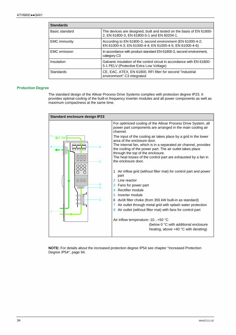
Protection Degree
The standard design of the Altivar Process Drive Systems complies with protection degree IP23. It provides optimal cooling of the built-in frequency inverter modules and all power components as well as maximum compactness at the same time.
Standard enclosure design IP23
For optimized cooling of the Altivar Process Drive System, all power part components are arranged in the main cooling air channel. The input of the cooling air takes place by a grid in the lower area of the enclosure door. The internal fan, which is in a separated air channel, provides the cooling of the power part. The air outlet takes place through the top of the enclosure. The heat losses of the control part are exhausted by a fan in the enclosure door. 1 Air inflow grid (without filter mat) for control part and power
part 2 Line reactor 3 Fans for power part 4 Rectifier module 5 Inverter module 6 dv/dt filter choke (from 355 kW built-in as standard) 7 Air outlet through metal grid with splash water protection 8 Air outlet (without filter mat) with fans for control part Air inflow temperature: -10...+50 °C
(below 0 °C with additional enclosure heating, above +40 °C with derating)
NOTE: For details about the increased protection degree IP54 see chapter "Increased Protection Degree IP54", page 94.

ATV660CQ4X1
NHA37111.02 35
Cooling concept
Control/monitoring of fans
The power part fans as well as the fans in the enclosure door are controlled energy optimized depending on the operation. Switching the fans on and off is derived from the start/stop request.
The fans in the power part are equipped with speed monitoring and the fans in the enclosure doors include a current monitoring and that helps to protect the Altivar Process Drive Systems. If one of these monitoring units triggers, a warning message is generated.
Furthermore, the operating hours of all fans can be monitored and a warning message can be triggered when the set limit is exceeded.
Overtemperature protection
The temperature of the power part is monitored all the time. In case of overtemperature the pulse frequency or the power is automatically reduced. The temperature of the control part is monitored with a thermostat. When the set temperature is exceeded, a warning message is generated. Only in case of insufficient cooling the drive is necessarily shut down.
Maximum Ambient Temperature
Depending on the chosen pulse frequency and the maximum ambient temperature a power reduction is necessary. This can be determined by means of the following diagrams.
Power reduction depending on the ambient temperature and pulse frequency Normal Duty ND Heavy Duty HD
Observe the following guidelines:
At higher pulse frequencies the allowed motor cable length is reduced (see chapter "Length of Motor Cables", page 70).
For full shaft power the motor size should not be more than one power rating bigger than the drive.
NOTE: If the ambient temperature is too high, the pulse frequency is automatically reduced which helps to prevent an overload of the inverter (except in case of operation with sinus-motor-filter).

ATV660CQ4X1
36 NHA37111.02
Specification
Technical Data ATV660C11Q4X1
Type ATV660C11Q4X1 Nominal data Normal Duty ND Heavy Duty HD (1) Typical motor rating Pn Un = 400 V 110 kW 90 kW Rated output current In 211 A 173 A Maximum current IMAX for 60 s per 10 minutes 232 A 260 A Input Rated input current Iin
(at Iscc = 22 kA) Un = 400 V 195 A 164 A
Rated apparent power Sn Un = 400 V 135 kVA 113 kVA Current harmonic THDi (2) < 48 % Protection for upstream cables Pre-fuse 250 A gG 250 A gG Circuit breaker Itherm 230 A 200 A Internal short-circuit protection Fuse 250 A aR Characteristics Efficiency at In 0.98 Heat losses at In Total losses 2530 W 2010 W Control part only 380 W 300 W Weight Net 300 kg Gross 340 kg Ambient conditions Air flow Power part 580 m3/h Control part 140 m3/h Sound pressure level 69 dB(A) Rated short-circuit current Icc Minimum 3 kA (3) Maximum 50 kA (100 ms) Cable cross section Mains connection (4)
Mains cable
1x (3x 150 mm²) or 2x (3x 70 mm²)
1x (3x 150 mm²) or 2x (3x 70 mm²)
Max. cable cross section 1x (3x 185 mm²) 1x (3x 185 mm²) Motor connection (5) Motor cable 1x (3x 120 mm²) or
2x (3x 50 mm²) 1x (3x 95 mm²)
Max. cable cross section 1x (3x 185 mm²) 1x (3x 185 mm²) (1) For Heavy Duty HD operation parameter [Dual Rating] drt has to be set to [High rating] HiGH
(see programming manual EAV64318). (2) For details see table under chapter "Mains Current Harmonics / Mains Voltage Distortion",
page 67. (3) Minimum mains short-circuit current (4) You will find further information at chapter "Mains Connection ", page 65. (5) You will find further information at chapter "Motor Connection", page 68.

ATV660CQ4X1
NHA37111.02 37
Dimensions IP23 for Size 1p
Interior View IP23 for Size 1p
NOTE: Following customizations affect the total dimensions: Increased protection degree IP54 Enclosure plinth for basic device Connection enclosure cable from top/bottom
ATV660CQ4X1
38 NHA37111.02
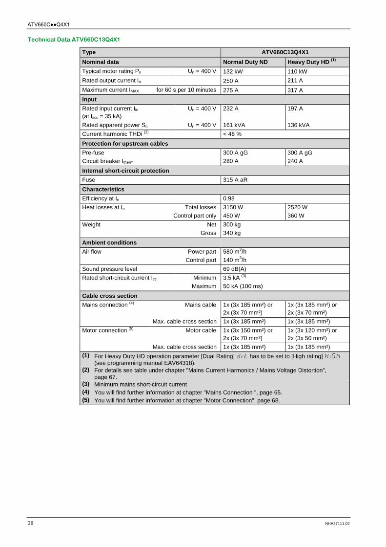
Technical Data ATV660C13Q4X1
Type ATV660C13Q4X1 Nominal data Normal Duty ND Heavy Duty HD (1) Typical motor rating Pn Un = 400 V 132 kW 110 kW Rated output current In 250 A 211 A Maximum current IMAX for 60 s per 10 minutes 275 A 317 A Input Rated input current Iin
(at Iscc = 35 kA) Un = 400 V 232 A 197 A
Rated apparent power Sn Un = 400 V 161 kVA 136 kVA Current harmonic THDi (2) < 48 % Protection for upstream cables Pre-fuse 300 A gG 300 A gG Circuit breaker Itherm 280 A 240 A Internal short-circuit protection Fuse 315 A aR Characteristics Efficiency at In 0.98 Heat losses at In Total losses 3150 W 2520 W Control part only 450 W 360 W Weight Net 300 kg Gross 340 kg Ambient conditions Air flow Power part 580 m3/h Control part 140 m3/h Sound pressure level 69 dB(A) Rated short-circuit current Icc Minimum 3.5 kA (3) Maximum 50 kA (100 ms) Cable cross section Mains connection (4)
Mains cable
1x (3x 185 mm²) or 2x (3x 70 mm²)
1x (3x 185 mm²) or 2x (3x 70 mm²)
Max. cable cross section 1x (3x 185 mm²) 1x (3x 185 mm²) Motor connection (5) Motor cable 1x (3x 150 mm²) or
2x (3x 70 mm²) 1x (3x 120 mm²) or 2x (3x 50 mm²)
Max. cable cross section 1x (3x 185 mm²) 1x (3x 185 mm²) (1) For Heavy Duty HD operation parameter [Dual Rating] drt has to be set to [High rating] HiGH
(see programming manual EAV64318). (2) For details see table under chapter "Mains Current Harmonics / Mains Voltage Distortion",
page 67. (3) Minimum mains short-circuit current (4) You will find further information at chapter "Mains Connection ", page 65. (5) You will find further information at chapter "Motor Connection", page 68.

ATV660CQ4X1
NHA37111.02 39
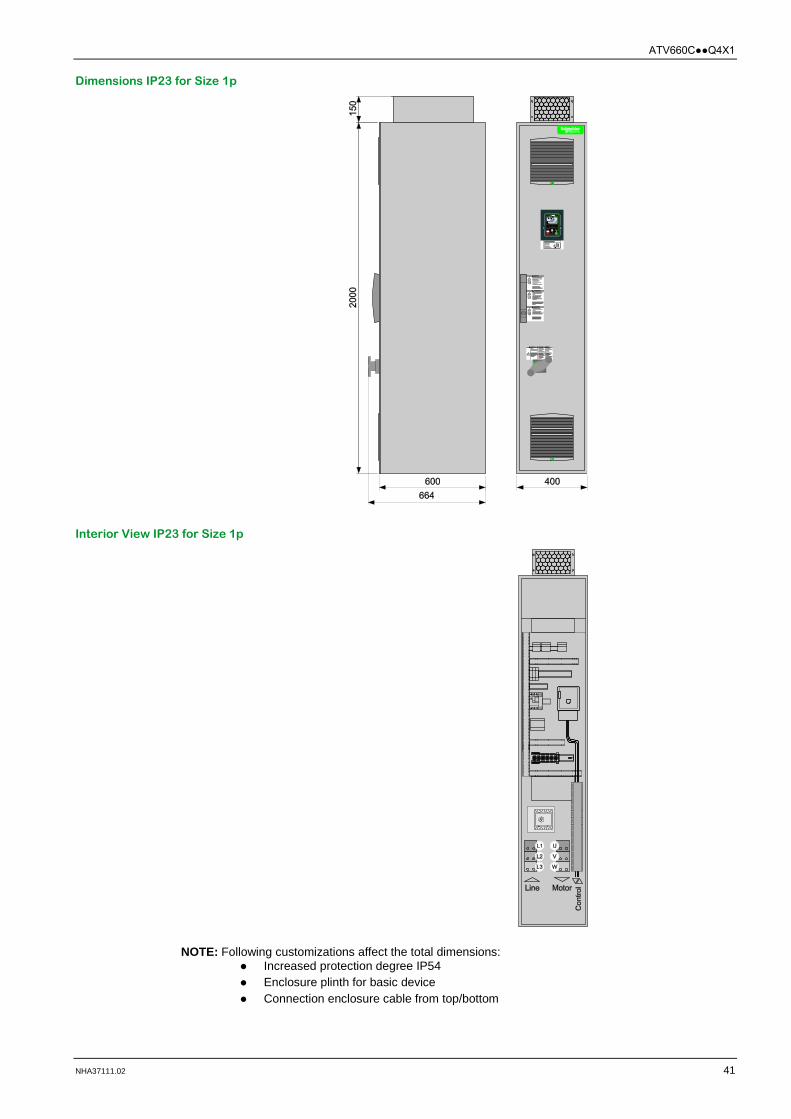
Dimensions IP23 for Size 1p
Interior View IP23 for Size 1p
NOTE: Following customizations affect the total dimensions: Increased protection degree IP54 Enclosure plinth for basic device Connection enclosure cable from top/bottom

ATV660CQ4X1
40 NHA37111.02
Technical Data ATV660C16Q4X1
Type ATV660C16Q4X1 Nominal data Normal Duty ND Heavy Duty HD (1) Typical motor rating Pn Un = 400 V 160 kW 132 kW Rated output current In 302 A 250 A Maximum current IMAX for 60 s per 10 minutes 332 A 375 A Input Rated input current Iin
(at Iscc = 35 kA) Un = 400 V 277 A 232 A
Rated apparent power Sn Un = 400 V 192 kVA 161 kVA Current harmonic THDi (2) < 48 % Protection for upstream cables Pre-fuse 315 A gG 300 A gG Circuit breaker Itherm 315 A 280 A Internal short-circuit protection Fuse 400 A aR Characteristics Efficiency at In 0.98 Heat losses at In Total losses 4030 W 3120 W Control part only 560 W 420 W Weight Net 300 kg Gross 340 kg Ambient conditions Air flow Power part 580 m3/h Control part 140 m3/h Sound pressure level 69 dB(A) Rated short-circuit current Icc Minimum 4 kA (3) Maximum 50 kA (100 ms) Cable cross section Mains connection (4)
Mains cable
1x (3x 185 mm²) or 2x (3x 95 mm²)
1x (3x 185 mm²) or 2x (3x 70 mm²)
Max. cable cross section 1x (3x 185 mm²) 1x (3x 185 mm²) Motor connection (5) Motor cable 1x (3x 185 mm²) or
2x (3x 95 mm²) 1x (3x 150 mm²) or 2x (3x 70 mm²)
Max. cable cross section 1x (3x 185 mm²) 1x (3x 185 mm²) (1) For Heavy Duty HD operation parameter [Dual Rating] drt has to be set to [High rating] HiGH
(see programming manual EAV64318). (2) For details see table under chapter "Mains Current Harmonics / Mains Voltage Distortion",
page 67. (3) Minimum mains short-circuit current (4) You will find further information at chapter "Mains Connection ", page 65. (5) You will find further information at chapter "Motor Connection", page 68.
ATV660CQ4X1
NHA37111.02 41
Dimensions IP23 for Size 1p
Interior View IP23 for Size 1p
NOTE: Following customizations affect the total dimensions: Increased protection degree IP54 Enclosure plinth for basic device Connection enclosure cable from top/bottom

ATV660CQ4X1
42 NHA37111.02
Technical Data ATV660C20Q4X1
Type ATV660C20Q4X1 Nominal data Normal Duty ND Heavy Duty HD (1) Typical motor rating Pn Un = 400 V 200 kW 160 kW Rated output current In 370 A 302 A Maximum current IMAX for 60 s per 10 minutes 407 A 453 A Input Rated input current Iin
(at Iscc = 35 kA) Un = 400 V 349 A 286 A
Rated apparent power Sn Un = 400 V 242 kVA 198 kVA Current harmonic THDi (2) < 48 % Protection for upstream cables Pre-fuse 400 A gG 355 A gG Circuit breaker Itherm 400 A 330 A Internal short-circuit protection Fuse 2x 250 A aR Characteristics Efficiency at In 0.98 Heat losses at In Total losses 4380 W 3380 W Control part only 580 W 430 W Weight Net 400 kg Gross 445 kg Ambient conditions Air flow Power part 1160 m3/h Control part 140 m3/h Sound pressure level 70 dB(A) Rated short-circuit current Icc Minimum 5.5 kA (3) Maximum 50 kA (100 ms) Cable cross section Mains connection (4)
Mains cable
2x (3x 120 mm²) or 3x (3x 70 mm²)
2x (3x 95 mm²)
Max. cable cross section 3x (3x 185 mm²) 3x (3x 185 mm²) Motor connection (5) Motor cable 2x (3x 120 mm²) or
3x (3x 70 mm²) 1x (3x 185 mm²) or 2x (3x 95 mm²)
Max. cable cross section 3x (3x 185 mm²) 3x (3x 185 mm²) (1) For Heavy Duty HD operation parameter [Dual Rating] drt has to be set to [High rating] HiGH
(see programming manual EAV64318). (2) For details see table under chapter "Mains Current Harmonics / Mains Voltage Distortion",
page 67. (3) Minimum mains short-circuit current (4) You will find further information at chapter "Mains Connection ", page 65. (5) You will find further information at chapter "Motor Connection", page 68.

ATV660CQ4X1
NHA37111.02 43
Dimensions IP23 for Size 2p
Interior View IP23 for Size 2p
NOTE: Following customizations affect the total dimensions: Increased protection degree IP54 Enclosure plinth for basic device Connection enclosure cable from top/bottom

ATV660CQ4X1
44 NHA37111.02
Technical Data ATV660C25Q4X1
Type ATV660C25Q4X1 Nominal data Normal Duty ND Heavy Duty HD (1) Typical motor rating Pn Un = 400 V 250 kW 200 kW Rated output current In 477 A 370 A Maximum current IMAX for 60 s per 10 minutes 525 A 555 A Input Rated input current Iin
(at Iscc = 50 kA) Un = 400 V 432 A 353 A
Rated apparent power Sn Un = 400 V 299 kVA 244 kVA Current harmonic THDi (2) < 47 % Protection for upstream cables Pre-fuse 500 A gG 400 A gG Circuit breaker Itherm 500 A 400 A Internal short-circuit protection Fuse 2x 315 A aR Characteristics Efficiency at In 0.98 Heat losses at In Total losses 5750 W 4340 W Control part only 730 W 520 W Weight Net 400 kg Gross 445 kg Ambient conditions Air flow Power part 1160 m3/h Control part 140 m3/h Sound pressure level 70 dB(A) Rated short-circuit current Icc Minimum 7 kA (3) Maximum 50 kA (100 ms) Cable cross section Mains connection (4)
Mains cable
2x (3x 185 mm²) or 3x (3x 95 mm²)
2x (3x 120 mm²) or 3x (3x 70 mm²)
Max. cable cross section 3x (3x 185 mm²) 3x (3x 185 mm²) Motor connection (5) Motor cable 2x (3x 150 mm²) or
3x (3x 95 mm²) 2x (3x 120 mm²) or 3x (3x 70 mm²)
Max. cable cross section 3x (3x 185 mm²) 3x (3x 185 mm²) (1) For Heavy Duty HD operation parameter [Dual Rating] drt has to be set to [High rating] HiGH
(see programming manual EAV64318). (2) For details see table under chapter "Mains Current Harmonics / Mains Voltage Distortion",
page 67. (3) Minimum mains short-circuit current (4) You will find further information at chapter "Mains Connection ", page 65. (5) You will find further information at chapter "Motor Connection", page 68.

ATV660CQ4X1
NHA37111.02 45
Dimensions IP23 for Size 2p
Interior View IP23 for Size 2p
NOTE: Following customizations affect the total dimensions: Increased protection degree IP54 Enclosure plinth for basic device Connection enclosure cable from top/bottom

ATV660CQ4X1
46 NHA37111.02
Technical Data ATV660C31Q4X1
Type ATV660C31Q4X1 Nominal data Normal Duty ND Heavy Duty HD (1) Typical motor rating Pn Un = 400 V 315 kW 250 kW Rated output current In 590 A 477 A Maximum current IMAX for 60 s per 10 minutes 649 A 716 A Input Rated input current Iin
(at Iscc = 50 kA) Un = 400 V 538 A 432 A
Rated apparent power Sn Un = 400 V 373 kVA 299 kVA Current harmonic THDi (2) < 42 % Protection for upstream cables Pre-fuse 630 A gG 500 A gG Circuit breaker Itherm 630 A 500 A Internal short-circuit protection Fuse 2x 400 A aR Characteristics Efficiency at In 0.98 Heat losses at In Total losses 7810 W 5700 W Control part only 990 W 680 W Weight Net 400 kg Gross 445 kg Ambient conditions Air flow Power part 1160 m3/h Control part 140 m3/h Sound pressure level 70 dB(A) Rated short-circuit current Icc Minimum 8 kA (3) Maximum 50 kA (100 ms) Cable cross section Mains connection (4)
Mains cable
3x (3x 150 mm²) or 4x (3x 95 mm²)
2x (3x 185 mm²) or 3x (3x 95 mm²)
Max. cable cross section 3x (3x 185 mm²) 3x (3x 185 mm²) Motor connection (5) Motor cable 2x (3x 185 mm²) or
3x (3x 120 mm²) 2x (3x 185 mm²) or 3x (3x 120 mm²)
Max. cable cross section 3x (3x 185 mm²) 3x (3x 185 mm²) (1) For Heavy Duty HD operation parameter [Dual Rating] drt has to be set to [High rating] HiGH
(see programming manual EAV64318). (2) For details see table under chapter "Mains Current Harmonics / Mains Voltage Distortion",
page 67. (3) Minimum mains short-circuit current (4) You will find further information at chapter "Mains Connection ", page 65. (5) You will find further information at chapter "Motor Connection", page 68.
ATV660CQ4X1
NHA37111.02 47
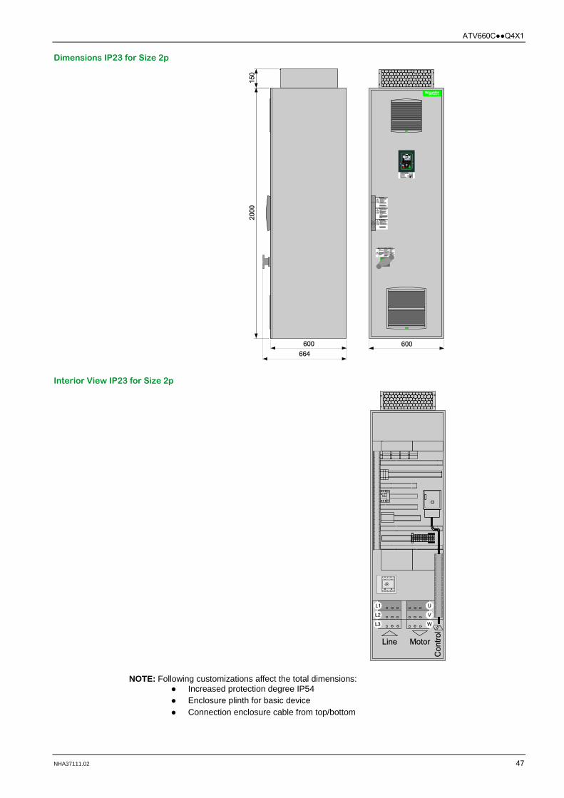
Dimensions IP23 for Size 2p
Interior View IP23 for Size 2p
NOTE: Following customizations affect the total dimensions: Increased protection degree IP54 Enclosure plinth for basic device Connection enclosure cable from top/bottom

ATV660CQ4X1
48 NHA37111.02
Technical Data ATV660C35Q4X1
Type ATV660C35Q4X1 Nominal data Normal Duty ND Heavy Duty HD (1) Typical motor rating Pn Un = 400 V 355 kW 280 kW Rated output current In 660 A 520 A Maximum current IMAX for 60 s per 10 minutes 726 A 780 A Input Rated input current Iin
(at Iscc = 50 kA) Un = 400 V 611 A 489 A
Rated apparent power Sn Un = 400 V 423 kVA 339 kVA Current harmonic THDi (2) < 46 % Protection for upstream cables Pre-fuse 800 A gG 630 A gG Circuit breaker Itherm 700 A 580 A Internal short-circuit protection Fuse 3x 315 A aR Characteristics Efficiency at In 0.98 Heat losses at In Total losses 8530 W 6410 W Control part only 930 W 650 W Weight Net 650 kg Gross 700 kg Ambient conditions Air flow Power part 1740 m3/h Control part 280 m3/h Sound pressure level 71 dB(A) Rated short-circuit current Icc Minimum 11 kA (3) Maximum 50 kA (100 ms) Cable cross section Mains connection (4)
Mains cable
4x (3x 150 mm²) 3x (3x 150 mm²) or 4x (3x 95 mm²)
Max. cable cross section 4x (3x 185 mm²) 4x (3x 185 mm²) Motor connection (5) Motor cable 3x (3x 150 mm²) or
4x (3x 95 mm²) 2x (3x 185 mm²) or 3x (3x 120 mm²)
Max. cable cross section 4x (3x 185 mm²) 4x (3x 185 mm²) (1) For Heavy Duty HD operation parameter [Dual Rating] drt has to be set to [High rating] HiGH
(see programming manual EAV64318). (2) For details see table under chapter "Mains Current Harmonics / Mains Voltage Distortion",
page 67. (3) Minimum mains short-circuit current (4) You will find further information at chapter "Mains Connection ", page 65. (5) You will find further information at chapter "Motor Connection", page 68.

ATV660CQ4X1
NHA37111.02 49
Dimensions IP23 for Size 3p
Interior View IP23 for Size 3p
NOTE: Following customizations affect the total dimensions: Increased protection degree IP54 Enclosure plinth for basic device Connection enclosure cable from top/bottom

ATV660CQ4X1
50 NHA37111.02
Technical Data ATV660C40Q4X1
Type ATV660C40Q4X1 Nominal data Normal Duty ND Heavy Duty HD (1) Typical motor rating Pn Un = 400 V 400 kW 315 kW Rated output current In 730 A 590 A Maximum current IMAX for 60 s per 10 minutes 803 A 885 A Input Rated input current Iin
(at Iscc = 50 kA) Un = 400 V 681 A 545 A
Rated apparent power Sn Un = 400 V 472 kVA 378 kVA Current harmonic THDi (2) < 43 % Protection for upstream cables Pre-fuse 800 A gG 630 A gG Circuit breaker Itherm 780 A 630 A Internal short-circuit protection Fuse 3x 315 A aR Characteristics Efficiency at In 0.98 Heat losses at In Total losses 9900 W 7370 W Control part only 1120 W 770 W Weight Net 650 kg Gross 700 kg Ambient conditions Air flow Power part 1740 m3/h Control part 280 m3/h Sound pressure level 71 dB(A) Rated short-circuit current Icc Minimum 11 kA (3) Maximum 50 kA (100 ms) Cable cross section Mains connection (4)
Mains cable
4x (3x 150 mm²)
3x (3x 150 mm²) or 4x (3x 95 mm²)
Max. cable cross section 4x (3x 185 mm²) 4x (3x 185 mm²) Motor connection (5) Motor cable 3x (3x 185 mm²) or
4x (3x 120 mm²) 3x (3x 120 mm²) or 4x (3x 95 mm²)
Max. cable cross section 4x (3x 185 mm²) 4x (3x 185 mm²) (1) For Heavy Duty HD operation parameter [Dual Rating] drt has to be set to [High rating] HiGH
(see programming manual EAV64318). (2) For details see table under chapter "Mains Current Harmonics / Mains Voltage Distortion",
page 67. (3) Minimum mains short-circuit current (4) You will find further information at chapter "Mains Connection ", page 65. (5) You will find further information at chapter "Motor Connection", page 68.

ATV660CQ4X1
NHA37111.02 51
Dimensions IP23 for Size 3p
Interior View IP23 for Size 3p
NOTE: Following customizations affect the total dimensions: Increased protection degree IP54 Enclosure plinth for basic device Connection enclosure cable from top/bottom

ATV660CQ4X1
52 NHA37111.02
Technical Data ATV660C45Q4X1
Type ATV660C45Q4X1 Nominal data Normal Duty ND Heavy Duty HD (1) Typical motor rating Pn Un = 400 V 450 kW 355 kW Rated output current In 830 A 660 A Maximum current IMAX for 60 s per 10 minutes 913 A 990 A Input Rated input current Iin
(at Iscc = 50 kA) Un = 400 V 764 A 611 A
Rated apparent power Sn Un = 400 V 529 kVA 423 kVA Current harmonic THDi (2) < 41 % Protection for upstream cables Pre-fuse 1000 A gG 800 A gG Circuit breaker Itherm 900 A 720 A Internal short-circuit protection Fuse 3x 400 A aR Characteristics Efficiency at In 0.98 Heat losses at In Total losses 11520 W 8460 W Control part only 1270 W 860 W Weight Net 650 kg Gross 700 kg Ambient conditions Air flow Power part 1740 m3/h Control part 280 m3/h Sound pressure level 71 dB(A) Rated short-circuit current Icc Minimum 13 kA (3) Maximum 50 kA (100 ms) Cable cross section Mains connection (4)
Mains cable 4x (3x 185 mm²) 4x (3x 150 mm²) Max. cable cross section 4x (3x 185 mm²) 4x (3x 185 mm²)
Motor connection (5) Motor cable 5x (3x 120 mm²) or 4x (3x 150 mm²)
3x (3x 150 mm²) or 4x (3x 95 mm²)
Max. cable cross section 4x (3x 185 mm²) 4x (3x 185 mm²) (1) For Heavy Duty HD operation parameter [Dual Rating] drt has to be set to [High rating] HiGH
(see programming manual EAV64318). (2) For details see table under chapter "Mains Current Harmonics / Mains Voltage Distortion",
page 67. (3) Minimum mains short-circuit current (4) You will find further information at chapter "Mains Connection ", page 65. (5) You will find further information at chapter "Motor Connection", page 68.

ATV660CQ4X1
NHA37111.02 53
Dimensions IP23 for Size 3p
Interior View IP23 for Size 3p
NOTE: Following customizations affect the total dimensions: Increased protection degree IP54 Enclosure plinth for basic device Connection enclosure cable from top/bottom

ATV660CQ4X1
54 NHA37111.02
Technical Data ATV660C50Q4X1
Type ATV660C50Q4X1 Nominal data Normal Duty ND Heavy Duty HD (1) Typical motor rating Pn Un = 400 V 500 kW 400 kW Rated output current In 900 A 730 A Maximum current IMAX for 60 s per 10 minutes 990 A 1095 A Input Rated input current Iin
(at Iscc = 50 kA) Un = 400 V 846 A 681 A
Rated apparent power Sn Un = 400 V 586 kVA 472 kVA Current harmonic THDi (2) < 39 % Protection for upstream cables Pre-fuse 1000 A gG 800 A gG Circuit breaker Itherm 1000 A 800 A Internal short-circuit protection Fuse 3x 400 A aR Characteristics Efficiency at In 0.98 Heat losses at In Total losses 13330 W 9800 W Control part only 1530 W 1020 W Weight Net 650 kg Gross 700 kg Ambient conditions Air flow Power part 1740 m3/h Control part 280 m3/h Sound pressure level 71 dB(A) Rated short-circuit current Icc Minimum 13 kA (3) Maximum 50 kA (100 ms) Cable cross section Mains connection (4)
Mains cable 4x (3x 185 mm²) 4x (3x 150 mm²) Max. cable cross section 4x (3x 185 mm²) 4x (3x 185 mm²)
Motor connection (5) Motor cable 5x (3x 120 mm²) or 4x (3x 185 mm²)
3x (3x 185 mm²) or 4x (3x 120 mm²)
Max. cable cross section 4x (3x 185 mm²) 4x (3x 185 mm²) (1) For Heavy Duty HD operation parameter [Dual Rating] drt has to be set to [High rating] HiGH
(see programming manual EAV64318). (2) For details see table under chapter "Mains Current Harmonics / Mains Voltage Distortion",
page 67. (3) Minimum mains short-circuit current (4) You will find further information at chapter "Mains Connection ", page 65. (5) You will find further information at chapter "Motor Connection", page 68.

ATV660CQ4X1
NHA37111.02 55
Dimensions IP23 for Size 3p
Interior View IP23 for Size 3p
NOTE: Following customizations affect the total dimensions: Increased protection degree IP54 Enclosure plinth for basic device Connection enclosure cable from top/bottom

ATV660CQ4X1
56 NHA37111.02
Technical Data ATV660C56Q4X1
Type ATV660C56Q4X1 Nominal data Normal Duty ND Heavy Duty HD (1) Typical motor rating Pn Un = 400 V 560 kW 450 kW Rated output current In 1020 A 830 A Maximum current IMAX for 60 s per 10 minutes 1122 A 1245 A Input Rated input current Iin
(at Iscc = 50 kA) Un = 400 V 948 A 767 A
Rated apparent power Sn Un = 400 V 656 kVA 531 kVA Current harmonic THDi (2) < 40 % Protection for upstream cables Pre-fuse 1250 A gG 1000 A gG Circuit breaker Itherm 1100 A 900 A Internal short-circuit protection Fuse 4x 400 A aR Characteristics Efficiency at In 0.98 Heat losses at In Total losses 13950 W 10500 W Control part only 1500 W 1050 W Weight Net 850 kg Gross 910 kg Ambient conditions Air flow Power part 2320 m3/h Control part 280 m3/h Sound pressure level 73 dB(A) Rated short-circuit current Icc Minimum 15 kA (3) Maximum 50 kA (100 ms) Cable cross section Mains connection (4)
Mains cable
5x (3x 185 mm²) or 6x (3x 150 mm²)
4x (3x 185 mm²) or 6x (3x 120 mm²)
Max. cable cross section 5x (3x 240 mm²) (6) 5x (3x 240 mm²) (6) Motor connection (5) Motor cable 5x (3x 150 mm²) 5x (3x 120 mm²) or
4x (3x 150 mm²) Max. cable cross section 5x (3x 240 mm²) (6) or
6x (3x 185 mm²) 5x (3x 240 mm²) (6) or 6x (3x 185 mm²)
(1) For Heavy Duty HD operation parameter [Dual Rating] drt has to be set to [High rating] HiGH (see programming manual EAV64318).
(2) For details see table under chapter "Mains Current Harmonics / Mains Voltage Distortion", page 67.
(3) Minimum mains short-circuit current (4) You will find further information at chapter "Mains Connection ", page 65. (5) You will find further information at chapter "Motor Connection", page 68. (6) Connection only with special cable lugs for switching devices according to IEC 61634 possible.
ATV660CQ4X1
NHA37111.02 57
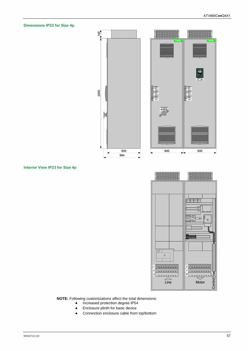
Dimensions IP23 for Size 4p
Interior View IP23 for Size 4p
NOTE: Following customizations affect the total dimensions: Increased protection degree IP54 Enclosure plinth for basic device Connection enclosure cable from top/bottom

ATV660CQ4X1
58 NHA37111.02
Technical Data ATV660C63Q4X1
Type ATV660C63Q4X1 Nominal data Normal Duty ND Heavy Duty HD (1) Typical motor rating Pn Un = 400 V 630 kW 500 kW Rated output current In 1140 A 900 A Maximum current IMAX for 60 s per 10 minutes 1254 A 1350 A Input Rated input current Iin
(at Iscc = 50 kA) Un = 400 V 1058 A 849 A
Rated apparent power Sn Un = 400 V 733 kVA 588 kVA Current harmonic THDi (2) < 38 % Protection for upstream cables Pre-fuse 1250 A gG 1000 A gG Circuit breaker Itherm 1250 A 1000 A Internal short-circuit protection Fuse 4x 400 A aR Characteristics Efficiency at In 0.98 Heat losses at In Total losses 16250 W 12000 W Control part only 1800 W 1250 W Weight Net 850 kg Gross 910 kg Ambient conditions Air flow Power part 2320 m3/h Control part 280 m3/h Sound pressure level 73 dB(A) Rated short-circuit current Icc Minimum 17 kA (3) Maximum 50 kA (100 ms) Cable cross section Mains connection (4)
Mains cable
5x (3x 185 mm²) or 6x (3x 150 mm²)
4x (3x 185 mm²) or 6x (3x 120 mm²)
Max. cable cross section 5x (3x 240 mm²) (6) 5x (3x 240 mm²) (6) Motor connection (5) Motor cable 5x (3x 150 mm²) or
4x (3x 240 mm²) (6) 5x (3x 150 mm²) or 4x (3x 240 mm²) (6)
Max. cable cross section 5x (3x 240 mm²) (6) or 6x (3x 185 mm²)
5x (3x 240 mm²) (6) or 6x (3x 185 mm²)
(1) For Heavy Duty HD operation parameter [Dual Rating] drt has to be set to [High rating] HiGH (see programming manual EAV64318).
(2) For details see table under chapter "Mains Current Harmonics / Mains Voltage Distortion", page 67.
(3) Minimum mains short-circuit current (4) You will find further information at chapter "Mains Connection ", page 65. (5) You will find further information at chapter "Motor Connection", page 68. (6) Connection only with special cable lugs for switching devices according to IEC 61634 possible.

ATV660CQ4X1
NHA37111.02 59
Dimensions IP23 for Size 4p
Interior View IP23 for Size 4p
NOTE: Following customizations affect the total dimensions: Increased protection degree IP54 Enclosure plinth for basic device Connection enclosure cable from top/bottom

ATV660CQ4X1
60 NHA37111.02
Technical Data ATV660C71Q4X1
Type ATV660C71Q4X1 Nominal data Normal Duty ND Heavy Duty HD (1) Typical motor rating Pn Un = 400 V 710 kW 560 kW Rated output current In 1260 A 1020 A Maximum current IMAX for 60 s per 10 minutes 1386 A 1530 A Input Rated input current Iin
(at Iscc = 50 kA) Un = 400 V 1192 A 951 A
Rated apparent power Sn Un = 400 V 826 kVA 659 kVA Current harmonic THDi (2) < 38 % Protection for upstream cables Pre-fuse 1600 A gG 1250 A gG Circuit breaker Itherm 1400 A 1100 A Internal short-circuit protection Fuse 5x 400 A aR Characteristics Efficiency at In 0.98 Heat losses at In Total losses 17600 W 13000 W Control part only 1900 W 1300 W Weight Net 1100 kg Gross 1165 kg Ambient conditions Air flow Power part 2900 m3/h Control part 420 m3/h Sound pressure level 74 dB(A) Rated short-circuit current Icc Minimum 18 kA (3) Maximum 50 kA (100 ms) Cable cross section Mains connection (4)
Mains cable
6x (3x 240 mm²) (6) or 8x (3x 150 mm²)
5x (3x 185 mm²) or 6x (3x 150 mm²)
Max. cable cross section 8x (3x 240 mm²) (6) 8x (3x 240 mm²) (6) Motor connection (5) Motor cable 5x (3x 185 mm²) 5x (3x 150 mm²)
Max. cable cross section 5x (3x 240 mm²) (6) or 6x (3x 185 mm²)
5x (3x 240 mm²) (6) or 6x (3x 185 mm²)
(1) For Heavy Duty HD operation parameter [Dual Rating] drt has to be set to [High rating] HiGH (see programming manual EAV64318).
(2) For details see table under chapter "Mains Current Harmonics / Mains Voltage Distortion", page 67.
(3) Minimum mains short-circuit current (4) You will find further information at chapter "Mains Connection ", page 65. (5) You will find further information at chapter "Motor Connection", page 68. (6) Connection only with special cable lugs for switching devices according to IEC 61634 possible.

ATV660CQ4X1
NHA37111.02 61
Dimensions IP23 for Size 5p
Interior View IP23 for Size 5p
NOTE: Following customizations affect the total dimensions: Increased protection degree IP54 Enclosure plinth for basic device Connection enclosure cable from top/bottom

ATV660CQ4X1
62 NHA37111.02
Technical Data ATV660C80Q4X1
Type ATV660C80Q4X1 Nominal data Normal Duty ND Heavy Duty HD (1) Typical motor rating Pn Un = 400 V 800 kW 630 kW Rated output current In 1420 A 1140 A Maximum current IMAX for 60 s per 10 minutes 1562 A 1710 A Input Rated input current Iin
(at Iscc = 50 kA) Un = 400 V 1335 A 1061 A
Rated apparent power Sn Un = 400 V 925 kVA 735 kVA Current harmonic THDi (2) < 36 % Protection for upstream cables Pre-fuse 1600 A gG 1250 A gG Circuit breaker Itherm 1600 A 1250 A Internal short-circuit protection Fuse 5x 400 A aR Characteristics Efficiency at In 0.98 Heat losses at In Total losses 20600 W 15080 W Control part only 2300 W 1580 W Weight Net 1100 kg Gross 1165 kg Ambient conditions Air flow Power part 2900 m3/h Control part 420 m3/h Sound pressure level 74 dB(A) Rated short-circuit current Icc Minimum 20 kA (3) Maximum 50 kA (100 ms) Cable cross section Mains connection (4)
Mains cable
6x (3x 240 mm²) (6) or 8x (3x 150 mm²)
5x (3x 185 mm²) or 6x (3x 150 mm²)
Max. cable cross section 8x (3x 240 mm²) (6) 8x (3x 240 mm²) (6) Motor connection (5) Motor cable 6x (3x 185 mm²) or
5x (3x 240 mm²) (6) 6x (3x 120 mm²) or 5x (3x 185 mm²)
Max. cable cross section 5x (3x 240 mm²) (6) or 6x (3x 185 mm²)
5x (3x 240 mm²) (6) or 6x (3x 185 mm²)
(1) For Heavy Duty HD operation parameter [Dual Rating] drt has to be set to [High rating] HiGH (see programming manual EAV64318).
(2) For details see table under chapter "Mains Current Harmonics / Mains Voltage Distortion", page 67.
(3) Minimum mains short-circuit current (4) You will find further information at chapter "Mains Connection ", page 65. (5) You will find further information at chapter "Motor Connection", page 68. (6) Connection only with special cable lugs for switching devices according to IEC 61634 possible.

ATV660CQ4X1
NHA37111.02 63
Dimensions IP23 for Size 5p
Interior View IP23 for Size 5p
NOTE: Following customizations affect the total dimensions: Increased protection degree IP54 Enclosure plinth for basic device Connection enclosure cable from top/bottom

ATV660CQ4X1
64 NHA37111.02
Circuit Diagram
The following diagram shows the typical wiring of the frequency inverter which may be required for protection of the plant or the device, depending on the use case.
ATV660 Altivar Process Drive Systems FUSE/CB External pre-fuse or circuit breaker to protect the mains cable MS Built-in main switch, lockable in open position T01 Control transformer 400 / 230 V AC MF aR fuses for short-circuit shut-down if the electronic protective devices do not work
properly RFI Built-in RFI filter
considering category C3 according to EN 61800-3 "Use in industrial environments" LC Line reactor to reduce the current harmonics on the mains caused by the DC link. REC Rectifier module(s) INV Inverter module(s) FC dv/dt filter choke to reduce the voltage load of the motor
(at some types a "dv/dt filter choke" is already integrated) CTRL Control panel with control block and further control components A01 Control terminals at the control block X200 / X205 Control terminals at the control panel M11 Fan in enclosure door
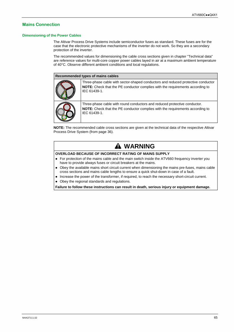
ATV660CQ4X1
NHA37111.02 65
Mains Connection
Dimensioning of the Power Cables
The Altivar Process Drive Systems include semiconductor fuses as standard. These fuses are for the case that the electronic protective mechanisms of the inverter do not work. So they are a secondary protection of the inverter.
The recommended values for dimensioning the cable cross sections given in chapter "Technical data" are reference values for multi-core copper power cables layed in air at a maximum ambient temperature of 40°C. Observe different ambient conditions and local regulations.
Recommended types of mains cables
Three-phase cable with sector-shaped conductors and reduced protective conductor NOTE: Check that the PE conductor complies with the requirements according to IEC 61439-1.
Three-phase cable with round conductors and reduced protective conductor. NOTE: Check that the PE conductor complies with the requirements according to IEC 61439-1.
NOTE: The recommended cable cross sections are given at the technical data of the respective Altivar Process Drive System (from page 36).
WARNING OVERLOAD BECAUSE OF INCORRECT RATING OF MAINS SUPPLY For protection of the mains cable and the main switch inside the ATV660 frequency inverter you
have to provide always fuses or circuit breakers at the mains. Obey the available mains short circuit current when dimensioning the mains pre-fuses, mains cable
cross sections and mains cable lengths to ensure a quick shut-down in case of a fault. Increase the power of the transformer, if required, to reach the necessary short-circuit current. Obey the regional standards and regulations. Failure to follow these instructions can result in death, serious injury or equipment damage.

ATV660CQ4X1
66 NHA37111.02
Overcurrent- and Short-circuit Protection
The following picture illustrates the overcurrent protection and short-circuit protection at the input side.
ATV660 Altivar Process Drive Systems FUSE External pre-fuse to protect the mains cable CB External circuit breaker to protect the mains cable (alternatively to FUSE) MS Built-in main switch, lockable in open position MF aR mains fuses for short-circuit shut-down if the electronic protective devices do not work
properly RFI Built-in RFI filter
considering category C3 according to EN 61800-3 "Use in industrial environments" LC Line reactor to reduce the current harmonics on the mains caused by the DC link. REC Rectifier module(s)
The Altivar Process Drive System includes semiconductor fuses as standard. These fuses are for the case that the electronic protective mechanisms of the inverter do not work. So they are a secondary protection of the inverter.
NOTE: If the mains fuses blow, the inverter already has a primary damage. Therefore, exchanging the blown fuses and switching the inverter on again without any check is not effective.
NOTE: The overcurrent protection is given at the technical data of the respective Altivar Process Drive System (from page 36).
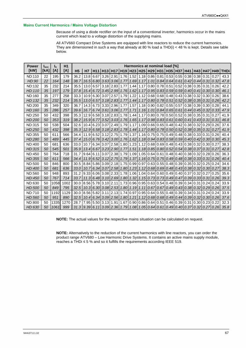
ATV660CQ4X1
NHA37111.02 67
Mains Current Harmonics / Mains Voltage Distortion
Because of using a diode rectifier on the input of a conventional inverter, harmonics occur in the mains current which lead to a voltage distortion of the supplying mains.
All ATV660 Compact Drive Systems are equipped with line reactors to reduce the current harmonics. They are dimensioned in such a way that already at 80 % load a THD(i) < 48 % is kept. Details see table below.
Power [kW]
Iscc [kA]
In [A]
H1 [A]
Harmonics at nominal load [%] H5 H7 H11 H13 H17 H19 H23 H25 H29 H31 H35 H37 H41 H43 H47 H49 THDi
ND:110 22 195 179 36.2 13.8 6.67 3.26 2.91 1.76 1.52 1.18 0.86 0.81 0.53 0.55 0.38 0.38 0.31 0.27 43.3 HD:90 22 164 148 38.7 16.5 6.80 3.63 3.06 1.77 1.69 1.17 1.01 0.84 0.64 0.61 0.42 0.44 0.31 0.32 47.8 ND:132 35 232 214 35.5 13.0 6.57 3.18 2.83 1.77 1.44 1.17 0.80 0.78 0.51 0.52 0.38 0.35 0.31 0.26 42.2 HD:110 35 197 179 37.8 15.4 6.72 3.45 2.99 1.76 1.62 1.17 0.95 0.83 0.59 0.59 0.40 0.41 0.30 0.30 46.1 ND:160 35 277 258 33.3 10.9 6.30 3.07 2.57 1.79 1.22 1.12 0.68 0.68 0.48 0.43 0.38 0.32 0.30 0.26 38.6 HD:132 35 232 214 35.5 13.0 6.57 3.18 2.83 1.77 1.44 1.17 0.80 0.78 0.51 0.52 0.38 0.35 0.31 0.26 42.2 ND:200 35 349 320 36.7 14.3 6.73 3.33 2.96 1.77 1.57 1.18 0.90 0.82 0.55 0.57 0.38 0.39 0.30 0.28 44.1 HD:160 35 286 257 39.6 16.7 6.74 3.61 3.06 1.77 1.71 1.16 1.01 0.84 0.65 0.61 0.44 0.45 0.32 0.33 47.9 ND:250 50 432 398 35.3 12.9 6.58 3.18 2.83 1.78 1.44 1.17 0.80 0.78 0.50 0.52 0.38 0.35 0.31 0.27 41.9 HD:200 50 353 319 38.2 15.9 6.77 3.52 3.03 1.76 1.65 1.17 0.98 0.83 0.61 0.60 0.41 0.43 0.31 0.31 46.8 ND:315 50 538 504 32.6 10.4 6.23 3.07 2.49 1.79 1.17 1.09 0.66 0.65 0.48 0.42 0.38 0.32 0.29 0.26 37.6 HD:250 50 432 398 35.3 12.9 6.58 3.18 2.83 1.78 1.44 1.17 0.80 0.78 0.50 0.52 0.38 0.35 0.31 0.27 41.9 ND:355 50 611 566 34.4 11.9 6.52 3.12 2.75 1.79 1.37 1.16 0.75 0.75 0.49 0.48 0.38 0.33 0.31 0.26 40.4 HD:280 50 489 445 37.4 15.0 6.76 3.42 3.00 1.76 1.62 1.18 0.94 0.83 0.58 0.59 0.40 0.42 0.30 0.30 45.3 ND:400 50 681 636 33.0 10.7 6.34 3.07 2.58 1.80 1.23 1.12 0.68 0.69 0.48 0.43 0.38 0.32 0.30 0.27 38.3 HD:315 50 545 501 35.9 13.4 6.67 3.23 2.90 1.77 1.51 1.18 0.85 0.80 0.52 0.54 0.38 0.37 0.31 0.27 42.8 ND:450 50 764 718 31.7 9.64 6.11 3.07 2.38 1.79 1.09 1.05 0.64 0.61 0.48 0.40 0.38 0.32 0.28 0.26 36.3 HD:355 50 611 566 34.4 11.9 6.52 3.12 2.75 1.79 1.37 1.16 0.75 0.75 0.49 0.48 0.38 0.33 0.31 0.26 40.4 ND:500 50 846 800 30.5 8.84 5.86 3.09 2.18 1.75 0.99 0.97 0.63 0.55 0.48 0.39 0.35 0.32 0.25 0.24 34.6 HD:400 50 681 636 33.0 10.7 6.34 3.07 2.58 1.80 1.23 1.12 0.68 0.69 0.48 0.43 0.38 0.32 0.30 0.27 38.3 ND:560 50 948 893 31.2 9.33 6.06 3.08 2.33 1.78 1.06 1.04 0.64 0.60 0.49 0.40 0.37 0.32 0.27 0.25 35.6 HD:450 50 767 714 33.7 11.3 6.48 3.10 2.69 1.80 1.32 1.15 0.73 0.73 0.49 0.47 0.39 0.33 0.31 0.26 39.3 ND:630 50 1058 1002 30.0 8.56 5.78 3.10 2.11 1.73 0.96 0.95 0.63 0.54 0.48 0.39 0.34 0.31 0.24 0.24 33.9 HD:500 50 849 795 32.5 10.3 6.30 3.08 2.53 1.80 1.19 1.11 0.67 0.67 0.49 0.43 0.38 0.32 0.29 0.26 37.5 ND:710 50 1192 1129 30.0 8.56 5.82 3.11 2.13 1.74 0.97 0.95 0.64 0.55 0.48 0.39 0.34 0.31 0.24 0.24 33.9 HD:560 50 951 890 32.5 10.4 6.34 3.09 2.56 1.80 1.21 1.12 0.68 0.68 0.49 0.44 0.39 0.32 0.30 0.26 37.6 ND:800 50 1335 1270 28.7 7.95 5.50 3.13 1.91 1.67 0.90 0.86 0.64 0.51 0.46 0.39 0.31 0.30 0.23 0.22 32.3 HD:630 50 1061 999 31.3 9.39 6.11 3.09 2.36 1.79 1.08 1.05 0.64 0.61 0.49 0.40 0.37 0.32 0.27 0.26 35.8
NOTE: The actual values for the respective mains situation can be calculated on request.
NOTE: Alternatively to the reduction of the current harmonics with line reactors, you can order the product range ATV680 – Low Harmonic Drive Systems. It contains an active mains supply module, reaches a THDi ≤ 5 % and so it fulfills the requirements according IEEE 519.

ATV660CQ4X1
68 NHA37111.02
Motor Connection
Assignment of the Motor
All Altivar Process Drive Systems include the function "Dual rating". It enables the use for drives with low overload "Normal duty" (typically pumps and fans) and, on the other hand, also the use with increased requirements regarding overload capability, starting torque, load impacts and control performance "Heavy duty" (e.g. compressors, mixers, rotary blowers,...).
You can select the desired power/overload capability with parameter [Dual rating] drt. When changing this parameter all relevant parameters are adapted to the selected property. For example, the parameters for motor power and motor current are modified accordingly.
In case of setting HD – Heavy Duty [High rating] HiGH the overload capability and the maximum overload current are increased. But at the same time the nominal motor power and the continuous output current of the frequency inverter are reduced. So you have to select a higher device type for the same motor power.
Example for ATV660C13Q4X1:
Normal Duty ND: 132 kW with 250 A continuous current and 275 A overload current for 60 s Nominal power Overload 10 % Factory setting:
[Normal rating] norMAL
Heavy Duty HD: 110 kW with 211 A continuous current and 317 A overload current for 60 s Lower nominal power Overload 50 % Selectable via parameter:
[High rating] HiGH
WARNING OVERLOAD OF THE MOTOR AND THE MOTOR CABLE DUE TO WRONG PARAMETERIZATION The Altivar Process Drive Systems are set to "Normal duty" when delivered. When resetting all parameters to factory setting, also "Normal duty" is set. Check before each commissioning the correct setting of parameter [Dual Rating] drt and the
motor data in menu [Simply start]. Failure to follow these instructions can result in death, serious injury or equipment damage.

ATV660CQ4X1
NHA37111.02 69
Dimensioning of the Motor Cables
The recommended values for dimensioning the cable cross sections given in chapter "Technical data" are reference values for multi-core copper power cables layed in air at a maximum ambient temperature of 40°C. Observe different ambient conditions and local regulations.
The motor cables are dimensioned for the maximum continuous current. They apply to 0...100 Hz (up to 300 Hz the cable losses increase about 25 % because of the Skin-effect).
The IGBT modules cause high-frequent interferences which drain off more and more stronger to the ground potential with increasing motor cable length. As a result the line-conducted interferences to the mains increase. In case of too long motor cables the attenuation of the mains filters is not longer sufficient and the permitted interference limits are exceeded.
Recommended types of motor cables
Symmetrically shielded cable with three phase conductors, symmetrically arranged PE conductor and a shield. NOTE: Check that the PE conductor complies with the requirements according to IEC 61439-1. Example: 2YSLCY-JB
Symmetrically shielded cable with three phase conductors and a concentrical PE conductor as shield. NOTE: Check that the shield (PE conductor) complies with the requirements according to IEC 61439-1. Example: NYCY / NYCWY
Symmetrically shielded cable with three phase conductors. NOTE: A separate PE conductor is required if the shield does not fulfill the requirements according to IEC 61439-1.
NOTE: The recommended cable cross sections are given at the technical data of the respective Altivar Process Drive System (from page 36).
WARNING OVERLOAD DUE TO WRONG MOTOR CABLE Only use symmetrical motor cables (see standard IEC 60034-25). Single-conductor cables are not recommended due to increased currents in the shield. Failure to follow these instructions can result in death, serious injury or equipment damage.

ATV660CQ4X1
70 NHA37111.02
Length of Motor Cables
Because of the permitted mains disturbances, the allowed overvoltages at the motor, the occurring bearing currents and the permitted heat losses the distance between inverter and motor(s) is limited. The maximum distance heavily depends on the used motors (insulation material), the type of motor cable used (shielded/unshielded), the cable laying (cable channel, underground installation, ...) as well as from the used options.
Dynamic voltage load of the motor
Overvoltages at the motor terminals result from reflection in the motor cable. Basically the motors are stressed with measurable higher voltage peaks from a motor cable length of 10 m. With the length of the motor cable also the value of overvoltage increases.
The steep edges of the switching impulses at the output side of the frequency inverter lead to a further load of the motors. The slew rate of the voltage is typically over 5 kV/µs but it decreases with the length of the motor cable.
The ATV660 frequency inverters are equipped with a dv/dt filter choke (at higher types a "dv/dt filter choke" is already integrated), which significantly reduces the load of the motors and so it is in accordance with the allowed limits.
Typical load of the motor Description
Load of the motor with overvoltage and slew rate when using conventional frequency inverters without integrated dv/dt filter chokes.
Reduced load of the motor by using Altivar Process Drive Systems with integrated dv/dt filter chokes 150 m (at higher types a "dv/dt filter choke" is already integrated). 1 When using a shielded motor cable 2 When using an unshielded motor cable 3 When using a shielded motor cable and a "dv/dt
filter choke 300 m". 4 When using an unshielded motor cable and a
"dv/dt filter choke 300 m".

ATV660CQ4X1
NHA37111.02 71
The motor standards for IEC and NEMA specify limits for the permitted load regarding slew rate and voltage peaks.
IEC 60034-17 – Permitted values for standard power supply driven motors at the frequency inverter, up to 500 V
IEC 60034-25 – Permitted values for "inverter motors" up to 500 V NEMA MG1 – Permitted values for "inverter motors" Typical measured values Description
The typical measured values as shown in the diagram correspond with the ATV660 frequency inverter variant with built-in dv/dt filter choke 150 m (at higher types a "dv/dt filter choke" is already integrated).
Motors according IEC 60034-25 as well as motors according NEMA MG1 are dimensioned for operation with frequency inverters and thus they are well qualified for drives with ATV660 frequency inverters.
Motors according IEC 60034-17 are dimensioned for operation with pure sinusoidal voltage, but they can also be operated at ATV660 when observing the permitted cable lengths and correct customization.
The Low Harmonic Drive Systems ATV680 and ATV980 offer significant improvement regarding motor load in comparison with older generations with active mains rectifiers AFE (as still offered from many competitors). By the new "3-level" system architecture the voltage load is the same as for ATV660 and ATV960 with classic diode rectifiers and so it not required to take it into account separately.
Basically for all motors from frame size 315 (approximately 110 kW) an insulated bearing on the non-drive end is recommended. It helps to prevent internal current flow inside the motor which can result from unbalances. The insulated bearing is to be understood as supplement to the dv/dt filter choke inside the frequency inverter.
CAUTION RISK OF OVERVOLTAGE AT THE MOTOR Observe the specified length of motor cables in order to protect the motor ! Failure to follow these instructions can result in injury or equipment damage.
ATV660CQ4X1
72 NHA37111.02
EMC interferences
The IGBT modules cause high-frequent interferences which drain off more and more stronger to the ground potential with increasing motor cable length. As a result the line-conducted interferences to the mains increase. In case of too long motor cables the attenuation of the mains filters is not longer sufficient and the permitted interference limits are exceeded.
CAUTION EXCEEDANCE OF EMC LIMITS Observe the maximum cable length given in the following table "Recommended maximum lengths of motor cables in second environment (industrial environment)" in order to keep the EMC limits. Failure to follow these instructions can result in injury or equipment damage.
Frequency inverters are a product of the restricted sales according to IEC 61800-3. In a residential environment this product can cause radio frequency interferences.
NOTICE RISK OF RADIO FREQUENCY INTERFERENCES If radio frequency interferences occur in a residential environment because of the operation of the frequency inverter, the user can be called on to take suitable measures. Failure to follow these instructions can result in equipment damage.
Bearing currents
The dv/dt filter choke inside the ATV660 frequency inverter effects a significant reduction of the common mode bearing currents.
Especially in case of big motors with middle up to high motor cable lengths the filter chokes are considerable to increase the availability of the motor.

ATV660CQ4X1
NHA37111.02 73
Multiplication factors
In case of conditions differing from the table the recommended cable lengths have to be converted by means of the following factors.
If several factors apply, please multiply them.
Correction of the max. cable lengths
The pulse frequency does not correspond to factory setting:
at 4 kHz multiply all values by 0.70
at 8 kHz multiply all values by 0.40
Output frequencies higher than 100 Hz. up to 200 Hz multiply all values by 0.80
up to 300 Hz multiply all values by 0.50
In case of 6-pole motor cabling (e.g. for star/delta starting circuit) multiply all values by 0.75
In case of parallel motors with a dedicated cable to each motor the inverter values have to be converted in compliance with the number of motors. When a motor choke is used for each motor, the following values in brackets apply.
at 2 motors multiply all values by 0.40 (0.80)
at 3 motors multiply all values by 0.25 (0.60)
at 4 motors multiply all values by 0.15 (0.40)
at 5 motors multiply all values by 0.10 (0.25)
In case of parallel motors with a common cable to all motors the inverter values have to be converted in compliance with the number of motors:
at 2 motors multiply all values by 0.80
at 3 motors multiply all values by 0.60
at 4 motors multiply all values by 0.40
at 5 motors multiply all values by 0.25
Recommended maximum lengths of motor cables in second environment (industrial environment)
EMC category (EN 61800-3)
ATV660 Customization Type of cable Max. cable length
C3 C11Q4X1…C31Q4X1 − Shielded 50 m
C11Q4X1…C31Q4X1 dv/dt filter choke 150m Shielded 150 m
C35Q4X1…C80Q4X1 − (1) Shielded 150 m
C4 C11Q4X1…C31Q4X1 − Unshielded 100 m
C11Q4X1…C31Q4X1 dv/dt filter choke 150m Unshielded 250 m
C35Q4X1…C80Q4X1 − (1) Unshielded 250 m
C11Q4X1…C80Q4X1 dv/dt filter choke 300m Shielded 300 m
C11Q4X1…C80Q4X1 dv/dt filter choke 300m Unshielded 500 m (1) At ATV660 Drive Systems from 355 kW the dv/dt filter choke 150m is built-in as standard.
NOTE: The specified lengths of motor cables are recommended limits based on typical motor cables, laying in cable channels, default pulse frequency and maximal output frequency of 100 Hz. Longer cable lengths are possible on request.
WARNING OVERLOAD BECAUSE OF TOO LONG MOTOR CABLE Observe the maximum cable length of 300 m shielded or 500 m unshielded to avoid inadmissible load of the motor. Failure to follow these instructions can result in death, serious injury or equipment damage.

ATV660CQ4X1
74 NHA37111.02
Thermal Motor Monitoring
In the Altivar Process Drive System several possibilities for thermal motor monitoring are available:
Standard sensor inputs AI2, AI3 at the control block Suitable temperature sensors: PTC, Pt100, Pt1000, KTY84
Sensor inputs AI4, AI5 at expansion card "Logic and analog I/O card" Suitable temperature sensors: PTC, Pt100, Pt1000, KTY84
DANGER HIGH VOLTAGES ON ACCESSIBLE PARTS Check whether the temperature sensors in the motor possess protective separation according
IEC 60664 to all parts carrying live voltage. Ensure that all connected equipments fulfill the PELV conditions. Failure to follow these instructions will result in death or serious injury.
On customer request the motor monitoring PTC, a PTC thermistor relay (alternatively with ATEX certificate), is installed and the sensor inputs are wired with the option terminals. The evaluation is performed via the diagnostics system in the Altivar Process Drive System.
On customer request the motor/bearing monitoring Pt100/Pt1000/KTY is installed, which includes
evaluation relays and the wiring of the sensor inputs to the option terminals. The evaluation is performed via the diagnostics system in the Altivar Process Drive System.
NOTE: When protective separation of the thermistor sensors in the motor cannot be guaranteed or in case of long motor cables, a PTC/Pt100/Pt1000/KTY thermistor relay is recommended.

ATV660CQ4X1
NHA37111.02 75
Customizations
Predefined Customizations
Customization Brief description Page Enclosure options Increased protection degree IP54 Enclosure designed in increased protection degree IP54 94
Enclosure plinth Enclosure plinth for basic device in protection degree IP23 95
Connection enclosure Separate connection enclosure; for connection of cables alternatively from top or from bottom.
95
Enclosure lighting Fluorescent lamp and a power socket 230 V AC 96
Enclosure heating Heats the enclosure in order to avoid frost and condensation at an ambient temperature up to -10°C
96
Control options Key switch "local / remote" Key switch in the enclosure door for switching between remote
control and local control 97
Ethernet port on front door Access to the Ethernet network directly on the enclosure door 97 I/O expansion cards Logic and analog I/O card Expansion card for additional analog and digital inputs and outputs
(6 digital inputs, 2 digital outputs, 2 analog inputs) 98
Relay output card Expansion card with three additional relay outputs 98 Communication cards Communication card Modbus TCP or EtherNet IP
Dual port option card for control of the inverter via Modbus TCP or EtherNet/IP
99
Communication card CANopen Daisy Chain
Option card for control of the inverter via CANopen Daisy Chain 99
Communication card CANopen SUB-D9
Option card for control of the inverter via CANopen with SUB-D port 99
Communication card CANopen with screw terminals
Option card for control of the inverter via CANopen with screw terminals
99
Communication card DeviceNet Option card for control of the inverter via DeviceNet 99
Communication card Profibus DP Option card for control of the inverter via Profibus DP V1 99
Communication card PROFINET Option card for control of the inverter via PROFINET 100 Functional safety STO - SIL 3 Stop category 0 This option effects a Safe Torque Off at the motor 101
STO - SIL 3 Stop category 1 This option effects a Safe Torque Off at the motor with controlled deceleration
101
Display options Front Display Module (FDM) Measuring device mounted in the enclosure door which indicates the
operating data 102
Indicator lamps on front door Three additional Indicator lamps mounted in the enclosure door which indicate the operating state
102

ATV660CQ4X1
76 NHA37111.02
Customization Brief description Page Motor options Motor monitoring PTC PTC thermistor relay to monitor the motor temperature via PTC
thermistors in the motor 103
Motor monitoring PTC with ATEX certificate
PTC thermistor relay to monitor the motor temperature via PTC thermistors in the motor with ATEX certificate
103
Motor monitoring Pt100/Pt1000/KTY Tripping unit to monitor the motor temperature via Pt100/Pt1000/KTY sensors in the motor winding
103
Bearing monitoring Pt100/Pt1000/KTY Tripping unit to monitor the motor temperature via Pt100/Pt1000/KTY sensors in the bearings of the motor
103
dv/dt filter choke 150 m Reduces the slew rate, peak voltage and common mode interferences on the output of the inverter and helps to protect the motor
104
dv/dt filter choke 300 m Helps to protect the motor winding and motor bearings in case of very long motor cable
104
Motor heating Includes a motor circuit breaker, a contactor and the terminals to connect a motor heating
104
Mains supply Circuit breaker Mains disconnect unit instead of the main switch, including door
handle 105
Undervoltage coil for circuit breaker 230 V
When there is no voltage at the undervoltage coil, the circuit breaker switches off
105
Motor for circuit breaker 230 V Remote control of the circuit breaker via control commands is possible by means of this motor drive.
106
12-pulse Supply Contains the components for 12-pulse supply 106
Automated mains disconnect Autonomous disconnection from the mains in case of a stop request, a detected fault or a safety disconnection via STO.
107
Safety labels in local language With this option the devices can be ordered with labels in the local language.
108
Modified wiring colors Modified wiring colors at the power cables 109 Monitoring Remote monitoring Records the data of the Drive Systems and provides them in the
Schneider Electric StruxureWare Energy Operation Network. 110
Packaging Seaworthy packaging This option contains a seaworthy packaging for transport by ship. 111

NHA37111.02 77
Chapter 4
Wiring of the Control Terminals
What Is in This Chapter?
This chapter contains the following topics:
Topic Page
Design/Position of the Individual Terminals 78
Control Block 79
Option "Logic and Analog I/O Card" 86
Option "Relay Output Card" 89
Option Terminals 90

Wiring of the Control Terminals
78 NHA37111.02
Wiring of the C ontrol Ter minals
Design/Position of the Individual Terminals
The Altivar Process Drive Systems are already equipped with extensive terminals on the control block as standard. The use and the function of all inputs and outputs can be parameterized.
In addition, there are the terminals X200 and X205, which are wired internally appropriate to the customizations.
For expansion the option cards Logic and analog I/O card and the relay output card are available. Both expansion cards can be installed, but the same card cannot be plugged twice.
Control block
Terminals X200, X205
Cable conduit
Signal wires
Voltage Supply and Auxiliary Voltage
All Drive Systems are equipped with a control transformer matching with the mains voltage and the required power. It provides a 230 V AC control voltage for supplying the fans in the enclosure doors and the DC supply units. The DC supply units generate 48 V DC for the internal power part fans and a 24 V DC auxiliary voltage. All control components are supplied by the internally provided voltages.
NOTE: For buffering the control block and with that keeping communication alive (e.g. fieldbus), the control block can be supplied via the terminals P24 and 0V externally with 24 V DC.

Wiring of the Control Terminals
NHA37111.02 79
Control Block
Structure of the Control Block
1 Control terminals of digital inputs 2 Control terminals of analog inputs 3 Control terminals of relay outputs 4 Control terminals STO (Safe Torque Off) and analog outputs 5 RJ45 port for door mounting kit of the graphic keypad 6 RJ45 port for Ethernet IP or Modbus TCP 7 Sink-Ext-Source selector switch 8 RJ45 port for serial Modbus 9 Slot for I/O expansion card 10 Slot for communication card or I/O expansion card

Wiring of the Control Terminals
80 NHA37111.02
Control Terminals at the Control Block
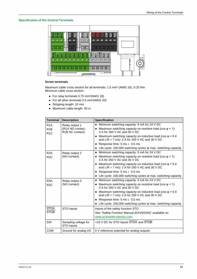
Wiring of the Control Terminals
NHA37111.02 81
Specification of the Control Terminals
Screw terminals
Maximum cable cross section for all terminals: 1.5 mm² (AWG 16), 0.25 Nm Minimum cable cross section:
For relay terminals 0.75 mm²(AWG 18) For all other terminals 0.5 mm²(AWG 20) Stripping length: 10 mm Maximum cable length: 50 m
Terminal Description Specification R1A R1B R1C
Relay output 1 (R1A NO contact, R1B NC contact)
Minimum switching capacity: 5 mA for 24 V DC Maximum switching capacity on resistive load (cos φ = 1):
3 A for 250 V AC and 30 V DC Maximum switching capacity on inductive load (cos φ = 0.4
and L/R = 7 ms): 2 A for 250 V AC and 30 V DC Response time: 5 ms ± 0.5 ms Life cycle: 100,000 switching cycles at max. switching capacity
R2A R2C
Relay output 2 (NO contact)
Minimum switching capacity: 5 mA for 24 V DC Maximum switching capacity on resistive load (cos φ = 1):
3 A for 250 V AC and 30 V DC Maximum switching capacity on inductive load (cos φ = 0.4
and L/R = 7 ms): 2 A for 250 V AC and 30 V DC Response time: 5 ms ± 0.5 ms Life cycle: 100,000 switching cycles at max. switching capacity
R3A R3C
Relay output 3 (NO contact)
Minimum switching capacity: 5 mA for 24 V DC Maximum switching capacity on resistive load (cos φ = 1):
3 A for 250 V AC and 30 V DC Maximum switching capacity on inductive load (cos φ = 0.4
and L/R = 7 ms): 2 A for 250 V AC and 30 V DC Response time: 5 ms ± 0.5 ms Life cycle: 100,000 switching cycles at max. switching capacity
STOA_____
, STOB_____
STO inputs Inputs of the safety function STO
See "Safety Function Manual (EAV64334)" available on www.schneider-electric.com.
24V Sampling voltage for STO inputs
+24 V DC for STO inputs STOA_____
and STOB_____
COM Ground for analog I/O 0 V reference potential for analog outputs
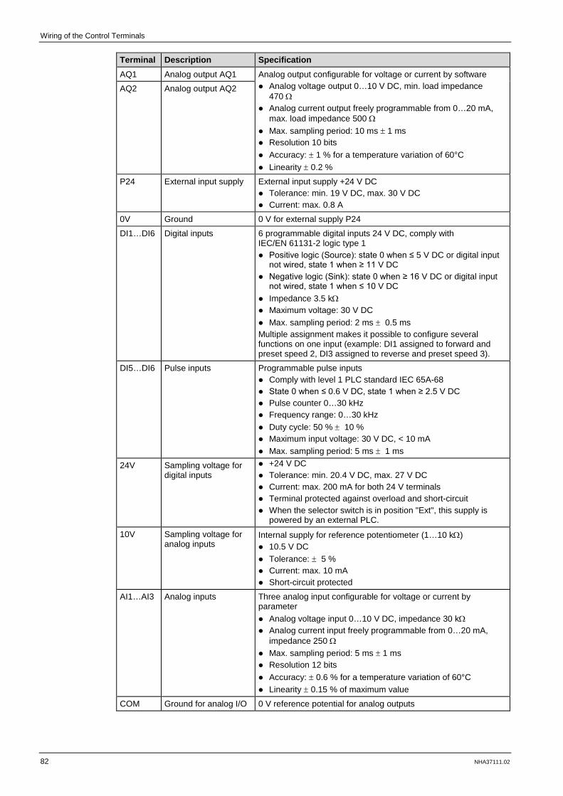
Wiring of the Control Terminals
82 NHA37111.02
Terminal Description Specification AQ1 Analog output AQ1 Analog output configurable for voltage or current by software
Analog voltage output 0…10 V DC, min. load impedance 470 Ω
Analog current output freely programmable from 0…20 mA, max. load impedance 500 Ω
Max. sampling period: 10 ms ± 1 ms Resolution 10 bits Accuracy: ± 1 % for a temperature variation of 60°C Linearity ± 0.2 %
AQ2 Analog output AQ2
P24 External input supply External input supply +24 V DC Tolerance: min. 19 V DC, max. 30 V DC Current: max. 0.8 A
0V Ground 0 V for external supply P24
DI1…DI6 Digital inputs 6 programmable digital inputs 24 V DC, comply with IEC/EN 61131-2 logic type 1 Positive logic (Source): state 0 when ≤ 5 V DC or digital input
not wired, state 1 when ≥ 11 V DC Negative logic (Sink): state 0 when ≥ 16 V DC or digital input
not wired, state 1 when ≤ 10 V DC Impedance 3.5 kΩ Maximum voltage: 30 V DC Max. sampling period: 2 ms ± 0.5 ms Multiple assignment makes it possible to configure several functions on one input (example: DI1 assigned to forward and preset speed 2, DI3 assigned to reverse and preset speed 3).
DI5…DI6 Pulse inputs Programmable pulse inputs Comply with level 1 PLC standard IEC 65A-68 State 0 when ≤ 0.6 V DC, state 1 when ≥ 2.5 V DC Pulse counter 0…30 kHz Frequency range: 0…30 kHz Duty cycle: 50 % ± 10 % Maximum input voltage: 30 V DC, < 10 mA Max. sampling period: 5 ms ± 1 ms
24V Sampling voltage for digital inputs
+24 V DC Tolerance: min. 20.4 V DC, max. 27 V DC Current: max. 200 mA for both 24 V terminals Terminal protected against overload and short-circuit When the selector switch is in position "Ext", this supply is
powered by an external PLC.
10V Sampling voltage for analog inputs
Internal supply for reference potentiometer (1…10 kΩ) 10.5 V DC Tolerance: ± 5 % Current: max. 10 mA Short-circuit protected
AI1…AI3 Analog inputs Three analog input configurable for voltage or current by parameter Analog voltage input 0…10 V DC, impedance 30 kΩ Analog current input freely programmable from 0…20 mA,
impedance 250 Ω Max. sampling period: 5 ms ± 1 ms Resolution 12 bits Accuracy: ± 0.6 % for a temperature variation of 60°C Linearity ± 0.15 % of maximum value
COM Ground for analog I/O 0 V reference potential for analog outputs
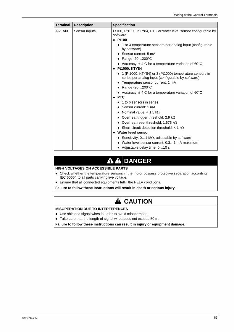
Wiring of the Control Terminals
NHA37111.02 83
Terminal Description Specification AI2, AI3 Sensor inputs Pt100, Pt1000, KTY84, PTC or water level sensor configurable by
software Pt100 1 or 3 temperature sensors per analog input (configurable
by software) Sensor current: 5 mA Range -20…200°C Accuracy: ± 4 C for a temperature variation of 60°C
Pt1000, KTY84 1 (Pt1000, KTY84) or 3 (Pt1000) temperature sensors in
series per analog input (configurable by software) Temperature sensor current: 1 mA Range -20…200°C Accuracy: ± 4 C for a temperature variation of 60°C
PTC 1 to 6 sensors in series Sensor current: 1 mA Nominal value: < 1.5 kΩ Overheat trigger threshold: 2.9 kΩ Overheat reset threshold: 1.575 kΩ Short-circuit detection threshold: < 1 kΩ
Water level sensor Sensitivity: 0…1 MΩ, adjustable by software Water level sensor current: 0.3…1 mA maximum Adjustable delay time: 0…10 s
DANGER HIGH VOLTAGES ON ACCESSIBLE PARTS Check whether the temperature sensors in the motor possess protective separation according
IEC 60664 to all parts carrying live voltage. Ensure that all connected equipments fulfill the PELV conditions. Failure to follow these instructions will result in death or serious injury.
CAUTION MISOPERATION DUE TO INTERFERENCES Use shielded signal wires in order to avoid misoperation. Take care that the length of signal wires does not exceed 50 m. Failure to follow these instructions can result in injury or equipment damage.

Wiring of the Control Terminals
84 NHA37111.02
Configuration of the Sink / Source Selector Switch
WARNING UNANTICIPATED EQUIPMENT OPERATION If the selector switch at the drive is set to Sink or Ext, do not connect the 0 V terminal to ground or
protective grounding. Verify for digital inputs configured for sink logic that accidental grounding cannot occur, caused for
example by damage to the signal cables. Follow all applicable standards and directives such as NFPA 79 and EN 60204 for proper control
circuit grounding practices. Failure to follow these instructions can result in death, serious injury or equipment damage.
The switch is used to adapt the operation of the digital inputs to the technology of the signal control. The switch is located below the control terminals (see picture at page 79).
Set the selector switch to SRC (Source) when using PLC outputs with PNP transistors (factory setting).
Set the switch to Ext (external) when using PLC outputs with NPN transistors.
Selector Switch in Position SRC (Source) and Internal Voltage Supply of the Digital Inputs
Selector Switch in Position SRC (Source) and External Voltage Supply of the Digital Inputs

Wiring of the Control Terminals
NHA37111.02 85
Selector Switch in Position SK (Sink) and Internal Voltage Supply of the Digital Inputs
Selector switch in position EXT (external) and external voltage supply of the digital inputs

Wiring of the Control Terminals
86 NHA37111.02
Option "Logic and Analog I/O Card"
Control terminals at the expansion card
Option to expand the control inputs and control outputs of the control block. The expansion card contains two analog inputs, six digital inputs and two digital outputs.

Wiring of the Control Terminals
NHA37111.02 87
Specification of the Control Terminals
Spring terminals Max. cable cross section: 1 mm² (AWG 16) Strip length: 10 mm Maximum cable length: 50 m
NOTE: You can select up to two option cards (either both I/O expansion cards or one I/O expansion card and one communication card). You will find further information at chapter "Expansion Card With Additional Inputs / Outputs", page 98.
Pin Terminal Description Specification
1 SHLD Shield connection for AI4 You can select between voltage, current, Pt100, Pt1000, KTY84 and PTC measurement by software configuration.
Differential voltage at the input circuit: Range: -10 V DC…+10 V DC Impedance: 20 kΩ Resolution: 11 bits + 1 sign bit Accuracy: ± 0.6 % for a temperature variation of 60 °C Linearity ± 0.15 % of maximum value
Current measurements: Range: freely programmable from 0…20 mA Impedance: 250 Ω Resolution: 12 bits Accuracy: ± 0.6 % for a temperature variation of 60 °C Linearity ± 0.15 % of maximum value Sampling period: 1 ms
PTx measurement: Pt100, Pt1000, PTC or KTY84 configurable by software Pt100 1 or 3 temperature sensors in series per analog input
(configurable by software) Temperature sensor current: max. 7.5 mA Range -20…200 °C Accuracy: ± 3°C for a temperature variation of 60 °C
Pt1000, KTY84 1 (Pt1000, KTY84) or 3 (Pt1000) temperature sensors in series
per analog input (configurable by software) Temperature sensor current: max. 1 mA Range -20…200 °C Accuracy: ± 3 C for a temperature variation of 60 °C
PTC 3 or 6 temperature sensors in series Temperature sensor current: max. 1 mA Nominal value: < 1.5 kΩ Overheat trigger threshold: 2.9 kΩ Overheat reset threshold: 1.575 kΩ Short-circuit detection threshold: < 1 kΩ Wire break detection: > 100 kΩ
2 AI4+ Differential analog input 4 Depending on software configuration: Measurement of differential
voltage PTx measurement 0…20 mA measurement Reference potential AI4- for
AI4+
3 AI4-
4 AI4+L Compensating connection for one temperature sensor Pt100, Pt1000 or KTY84 in 3-wire-design
5 SHLD Shield connection for AI5
6 AI5+ Differential analog input 5 Depending on software configuration: Measurement of differential
voltage PTx measurement 0…20 mA measurement Reference potential AI5- for
AI5+
7 AI5-
8 AI5+L Compensating connection for one temperature sensor Pt100, Pt1000 or KTY84 in 3-wire-design

Wiring of the Control Terminals
88 NHA37111.02
Pin Terminal Description Specification
9 DQ12 Digital output 12 The 24 V DC digital outputs DQ comply with the standard IEC/EN 61131-2. Logic type selected by DQCOM wiring Output voltage: ≤ 30 V DC Switching capability: ≤ 100 mA Voltage drop at 100 mA load: ≤ 3 V DC Response time: 1 ms
10 DICOM Reference potential for the digital inputs
The 24 V DC digital inputs DI are galvanically isolated via optocoupler and comply with the standard IEC/EN 61131-2. Logic type selected by DICOM wiring Positive logic (Source): state 0 when ≤ 5 V DC, state 1 when ≥
11 V DC Negative logic (Sink): state 0 when ≥ 16 V DC, state 1 when ≤
10 V DC Maximum voltage: ≤ 30 V DC Input current (typically): 2.5 mA Sampling period: 1 ms
11 DI11 Digital input 11
12 DI12 Digital input 12
13 DI13 Digital input 13
14 DI14 Digital input 14
15 DI15 Digital input 15
16 DI16 Digital input 16
17 DQCOM Reference potential for the digital outputs
The 24 V DC digital outputs DQ comply with the standard IEC/EN 61131-2. Logic type selected by DQCOM wiring Output voltage: ≤ 30 V DC Switching capability: ≤ 100 mA Voltage drop at 100 mA load: ≤ 3 V DC Response time: 1 ms
18 DQ11 Digital output 11
DANGER HIGH VOLTAGES ON ACCESSIBLE PARTS Check whether the temperature sensors in the motor possess protective separation according
IEC 60664 to all parts carrying live voltage. Ensure that all connected equipments fulfill the PELV conditions. Failure to follow these instructions will result in death or serious injury.
CAUTION MISOPERATION DUE TO INTERFERENCES Use shielded signal wires in order to avoid misoperation. Take care that the length of signal wires does not exceed 50 m. Failure to follow these instructions can result in injury or equipment damage.

Wiring of the Control Terminals
NHA37111.02 89
Option "Relay Output Card"
Control terminals at the expansion card
Specification of the Control Terminals rauf
Screw terminals Maximum cable cross section: 1.5 mm² (AWG 16) Maximum tightening torque: 0.5 Nm (4.4 lb.in) Minimum cable cross section: 0.75 mm² (AWG 18) Strip length: 10 mm
NOTE: You can select up to two option cards (either both I/O expansion cards or one I/O expansion card and one communication card). You will find futher information at chapter "Expansion Card With Relay Outputs", page 98.
Pin Terminal Description Specification 1 R4A Relay output 4
(NO contact) Programmable relay output 4: Minimum switching capacity: 5 mA for 24 V DC Maximum switching capability on resistive load (cos φ = 1):
3 A for 250 V AC and 30 V DC Maximum switching capability on inductive load (cos φ = 0.4
and L/R = 7 ms): 2 A for 250 V AC and 30 V DC Response time: 5 ms ± 0.5 ms Life cycle: 100,000 switching cycles at max. switching
capacity
2 R4C
3 R5A Relay output 5 (NO contact)
Programmable relay output 5: Minimum switching capacity: 5 mA for 24 V DC Maximum switching capability on resistive load (cos φ = 1):
3 A for 250 V AC and 30 V DC Maximum switching capability on inductive load (cos φ = 0.4
and L/R = 7 ms): 2 A for 250 V AC and 30 V DC Response time: 5 ms ± 0.5 ms Life cycle: 100,000 switching cycles at max. switching
capacity
4 R5C
5 R6A Relay output 6 (NO contact)
Programmable relay output 6: Minimum switching capacity: 5 mA for 24 V DC Maximum switching capability on resistive load (cos φ = 1):
3 A for 250 V AC and 30 V DC Maximum switching capability on inductive load (cos φ = 0.4
and L/R = 7 ms): 2 A for 250 V AC and 30 V DC Response time: 5 ms ± 0.5 ms Life cycle: 100,000 switching cycles at max. switching
capacity
6 R6C

Wiring of the Control Terminals
90 NHA37111.02
Option Terminals
Control Terminals at the Option Terminals
The option terminals X200 and X205 are built-in at each Altivar Process Drive System as standard. They are designed as pluggable terminals.
Spring terminals pluggable
Max. cable cross section: 2.5 mm² [AWG 12] Min. cable cross section: 0.25 mm² [AWG 26] Strip length: 10 mm
22
11
21
10
20
9
19
8
18
7
17
6
16
5
15
4
14
3
13
2
12
1
16
8
15
7
14
6
13
5
12
4
11
3
10
2
9
1
X200
X205

Wiring of the Control Terminals
NHA37111.02 91
Specification of the Control Terminals
As shown in the following illustration, there are following connections available for the customer depending on the chosen options.

Wiring of the Control Terminals
92 NHA37111.02

NHA37111.02 93
Chapter 5
Customizations
What Is in This Chapter?
This chapter contains the following topics:
Topic Page
Enclosure Options 94
Control Options 97
I/O Expansion Cards 98
Communication Cards 99
Functional Safety 101
Display Options 102
Motor Options 103
Mains Supply 105
Wiring Colors 109
Monitoring Options 110
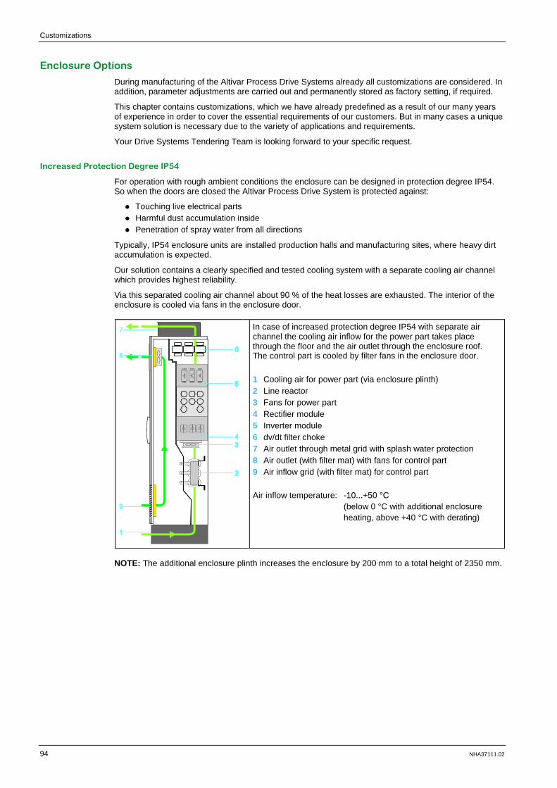
Customizations
94 NHA37111.02
Customizations
Enclosure Options
During manufacturing of the Altivar Process Drive Systems already all customizations are considered. In addition, parameter adjustments are carried out and permanently stored as factory setting, if required.
This chapter contains customizations, which we have already predefined as a result of our many years of experience in order to cover the essential requirements of our customers. But in many cases a unique system solution is necessary due to the variety of applications and requirements.
Your Drive Systems Tendering Team is looking forward to your specific request.
Increased Protection Degree IP54
For operation with rough ambient conditions the enclosure can be designed in protection degree IP54. So when the doors are closed the Altivar Process Drive System is protected against:
Touching live electrical parts Harmful dust accumulation inside Penetration of spray water from all directions
Typically, IP54 enclosure units are installed production halls and manufacturing sites, where heavy dirt accumulation is expected.
Our solution contains a clearly specified and tested cooling system with a separate cooling air channel which provides highest reliability.
Via this separated cooling air channel about 90 % of the heat losses are exhausted. The interior of the enclosure is cooled via fans in the enclosure door.
In case of increased protection degree IP54 with separate air channel the cooling air inflow for the power part takes place through the floor and the air outlet through the enclosure roof. The control part is cooled by filter fans in the enclosure door. 1 Cooling air for power part (via enclosure plinth) 2 Line reactor 3 Fans for power part 4 Rectifier module 5 Inverter module 6 dv/dt filter choke 7 Air outlet through metal grid with splash water protection 8 Air outlet (with filter mat) with fans for control part 9 Air inflow grid (with filter mat) for control part Air inflow temperature: -10...+50 °C
(below 0 °C with additional enclosure heating, above +40 °C with derating)
NOTE: The additional enclosure plinth increases the enclosure by 200 mm to a total height of 2350 mm.
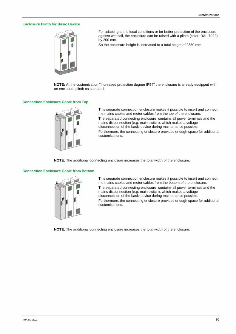
Customizations
NHA37111.02 95
Enclosure Plinth for Basic Device
For adapting to the local conditions or for better protection of the enclosure against wet soil, the enclosure can be raised with a plinth (color: RAL 7022) by 200 mm. So the enclosure height is increased to a total height of 2350 mm.
NOTE: At the customization "Increased protection degree IP54" the enclosure is already equipped with an enclosure plinth as standard.
Connection Enclosure Cable from Top
This separate connection enclosure makes it possible to insert and connect the mains cables and motor cables from the top of the enclosure. The separated connecting enclosure contains all power terminals and the mains disconnection (e.g. main switch), which makes a voltage disconnection of the basic device during maintenance possible. Furthermore, the connecting enclosure provides enough space for additional customizations.
NOTE: The additional connecting enclosure increases the total width of the enclosure.
Connection Enclosure Cable from Bottom
This separate connection enclosure makes it possible to insert and connect the mains cables and motor cables from the bottom of the enclosure. The separated connecting enclosure contains all power terminals and the mains disconnection (e.g. main switch), which makes a voltage disconnection of the basic device during maintenance possible. Furthermore, the connecting enclosure provides enough space for additional customizations.
NOTE: The additional connecting enclosure increases the total width of the enclosure.

Customizations
96 NHA37111.02
Enclosure Lighting lostssddd
In order to make maintenance easier, the enclosure can be equipped with a lighting, which is switched on when opening the enclosure door.
The lighting is externally supplied and so it is also available at switched off mains supply. Furthermore, a power socket according to VDE standard (230 V / 50 Hz, 2 A) is located on the lighting to operate smaller consumers on-site.
NOTE: The additional power supply at terminals X200 has to be provided by the user.
Rated voltage: Rated frequency: Rated power:
230 V 50/60 Hz 500 VA
DANGER HAZARD OF ELECTRIC SHOCK Take care that the external supply fulfills the personal safety requirements. Failure to follow these instructions will result in death or serious injury.
Enclosure Heating
This customization is used to heat the enclosure in order to avoid frost and condensation at an ambient temperature up to -10°C. The enclosure heating is externally supplied, so the enclosure can be also heated when mains supply is switched off.
NOTE: The additional power supply at terminals X200 has to be provided by the user.
Rated voltage: Rated frequency: Rated power:
230 V 50/60 Hz 400...800 VA
DANGER HAZARD OF ELECTRIC SHOCK Take care that the external supply fulfills the personal safety requirements. Failure to follow these instructions will result in death or serious injury.

Customizations
NHA37111.02 97
Control Options
Key Switch "local / remote"
The key switch "local / remote" allows to switch between local operation (via the graphical operating panel) or remote control (terminals or bus). The switch can be only operated with a key and so it can be only switched by authorized personnel.
Ethernet Port on Front Door
The Ethernet port in the enclosure door allows access to the frequency inverter without opening the enclosure door. The plug can be closed with a dust protection cap.

Customizations
98 NHA37111.02
I/O Expansion Cards
You will find detailed information in the respective documentation. See listing under chapter "Related Documents", page 9.
NOTE: You can select up to two option cards (either both I/O expansion cards or one I/O expansion card and one communication card).
Expansion Card With Additional Inputs / Outputs
Expansion card for additional analog and digital inputs and outputs (6 digital inputs, 2 digital outputs, 2 analog inputs)
You will find further information at chapter "Option "Logic and Analog I/O Card"", page 86.
Expansion Card With Relay Outputs
Expansion card with three additional relay outputs
You will find further information at chapter "Option "Relay Output Card"", page 89.

Customizations
NHA37111.02 99
Communication Cards
You will find detailed information in the respective documentation. See listing under chapter "Related Documents", page 9.
NOTE: You can only select one communication card.
Communication Card Modbus TCP or EtherNet IP
Dual port option card for control of the inverter via Modbus TCP or EtherNet/IP
Communication Card CANopen Daisy Chain
Option card for control of the inverter via CANopen Daisy Chain
Communication Card CANopen SUB-D9
Option card for control of the inverter via CANopen with SUB-D port.
Communication Card CANopen With Screw Terminals
Option card for control of the inverter via CANopen with screw terminals
Communication Card DeviceNet
Option card for control of the inverter via DeviceNet
Communication Card Profibus DP
Option card for control of the inverter via Profibus DP V1

Customizations
100 NHA37111.02
Communication Card PROFINET
Option card for control of the inverter via PROFINET

Customizations
NHA37111.02 101
Functional Safety
Safe Torque Off (STO)
The Altivar Process is equipped with the safety function "Safe Torque Off STO" according to ISO 13849-1, IEC/EN 61508, IEC/EN 60204-1, which helps to prevent any unintended start-up of the motor.
Inputs STOA_____
and STOB_____
directly at the control terminals of the control block. This function fulfills, when correctly wired, the machine standard ISO 13849-1, Performance level PL e, the IEC/EN 61508 Safety integrity level SIL 3 standard for functional safety and the power drive system standard IEC/EN 61800-5-2.
Customization SIL3, stop category 0 / PL e The triggering of the safety function leads to a free-wheeling of the drive and helps to prevent an unintended restart.
Customization SIL3, stop category 1 / PL e The triggering of this function starts a controlled deceleration, shuts down the drive after the set time and helps to prevent an unintended restart.
NOTE: More details about the function "Safe Torque OFF" are given in the "Safety Function Manual (EAV64334)" on www.schneider-electric.com.
Safe Torque Off STO – SIL 3 Stop Category 0 / Performance Level PL e
Via an EMERGENCY STOP button in the enclosure door or further implemented, external monitoring equipment, the torque at the motor can be switched off according SIL 3 stop category 0 / performance level PL e. The triggering of the safety function leads to a free-wheeling of the drive and helps to prevent an unintended restart.
Safe Torque Off STO – SIL 3 Stop Category 1 / Performance Level PL e
Via an EMERGENCY STOP button in the enclosure door or further implemented, external monitoring equipment, the torque at the motor can be switched off according SIL 3 stop category 1 / performance level PL e. The triggering of this function starts a controlled deceleration, shuts down the drive after the set time and helps to prevent an unintended restart.

Customizations
102 NHA37111.02
Display Options
Front Display Module (FDM)
A display element mounted in the enclosure door enables clear indication of real-time values like:
Indication of mains currents (3x) Mains voltages (3x phase voltages, 3x phase-to-phase voltages) Mains power
These values can be indicated graphically or digital.
The display element is provided with backlight for increased readability.
Indicator Lamps on Front Door
For quick, optical diagnostics of the actual operating state from a greater distance, the enclosure can be equipped with indicator lamps. The lamps show following operating states:
Operating state Indicator lamp Labeling Ready Yellow READY
Operation Green RUN
Detected fault Red TRIP
Ver knüpfte Gr afi ken:

Customizations
NHA37111.02 103
Motor Options
Motor Monitoring PTC
If the motor is equipped with integrated thermistor sensors to help to protect against thermal overload, they can be directly connected to the sensor inputs of the Altivar Process Drive System.
If the frequency inverter detects an overtemperature at the motor, the drive stops the motor and generates an error message at the display. This operating state is also forwarded to the status relays and to the fieldbus.
NOTE: When protective separation of the thermistor sensors in the motor cannot be guaranteed or in case of long motor cables, a PTC/Pt100/Pt1000/KTY thermistor relay is recommended.
Motor Monitoring PTC with ATEX Certificate
The motor monitoring PTC with ATEX certificate is used to monitor the thermistor sensors of motors which are installed in hazardous area (explosive atmosphere).
If the frequency inverter detects the overtemperature at the motor, the drive stops the motor and generates an error message at the display. This operating state is also forwarded to the status relays and to the fieldbus. The monitoring relay additionally triggers a safe shut-down of the drive.
DANGER OPERATION IN HAZARDOUS AREAS (EXPLOSIVE ATMOSPHERE) Install the Altivar Process Drive System outside of hazardous area (explosive atmosphere). For operation of motors in hazardous area (explosive atmosphere) the option "Motor monitoring
PTC with ATEX certificate" is necessary. Failure to follow these instructions will result in death or serious injury.
Motor monitoring Pt100/Pt1000/KTY Verknüpfte Grafiken:
If the motor is equipped with integrated temperature sensors in the winding to help to protect against thermal overload, they can be directly connected to the sensor inputs of the Altivar Process Drive System.
If the set temperature at the motor is exceeded, a warning message is generated. When the temperature is further rising over a set value, the drive is stopped and an error message is generated. The operating states are also forwarded to the status relays and to the fieldbus.
NOTE: When protective separation of the thermistor sensors in the motor cannot be guaranteed or in case of long motor cables, a PTC/Pt100/Pt1000/KTY thermistor relay is recommended.
Bearing Monitoring Pt100/Pt1000/KTY Verknüpfte Grafiken: Geräte\Optionen\Optionen_Motorueberwachung_V00.eps
If the motor is equipped with integrated temperature sensors in the bearings to help to protect against thermal overload, they can be directly connected to the sensor inputs of the Altivar Process Drive System.
If the set temperature at the motor is exceeded, a warning message is generated. When the temperature is further rising over a set value, the drive is stopped and an error message is generated. The operating states are also forwarded to the status relays and to the fieldbus.

Customizations
104 NHA37111.02
NOTE: When protective separation of the thermistor sensors in the motor cannot be guaranteed or in case of long motor cables, a PTC/Pt100/Pt1000/KTY thermistor relay is recommended.
dv/dt Filter Choke 150 m
The use of the customization dv/dt filter choke 150 m has significant advantages concerning the operation of the drive: Decrease of the dv/dt and peak voltage load of the motor Prevention of common mode bearing currents in the motor –
especially important at high power Great reduction of the influences to other cables – important if the
separate laying of motor cables is not possible In case of long motor cables up to 150 m shielded or up to 250 m
unshielded dv/dt filter choke 150 m can be installed without enlarged
enclosure width.
NOTE: You will find further information about long motor cables under chapter "Length of Motor Cables", page 70.
dv/dt Filter Choke 300 m
The use of the customization dv/dt filter choke 300 m has significant advantages concerning the operation of the drive: Decrease of the dv/dt and peak voltage load of the motor Prevention of common mode bearing currents in the motor –
especially important at high power Great reduction of the influences to other cables – important if the
separate laying of motor cables is not ensured In case of long motor cables up to 300 m shielded or up to 500 m
unshielded dv/dt filter choke 300 m can be installed without enlarged
enclosure width.
NOTE: You will find further information about long motor cables under chapter "Length of Motor Cables", page 70.
Motor Heating
The motor standstill heating is used to avoid condensate and frost damages at standstill of the motors in cold environment. It is activated when the motor is shut down.

Customizations
NHA37111.02 105
Mains Supply
Circuit Breaker
The circuit breaker is used for mains disconnection instead of the main switch. It is operated by a handle in the enclosure door. The circuit breaker can be optionally equipped with an undervoltage coil and motor.
Undervoltage Coil for Circuit Breaker 230 V
When there is no voltage at the undervoltage coil, the circuit breaker switches off. The undervoltage coil is built into the circuit breaker and is wired to the option terminals.
Specification of the control terminals X200: 6/14 External control voltage 220…240 V AC 50/60 Hz
NOTE: Only when control voltage is applied, the circuit breaker can be switched on manually. You will find further information about the topic wiring under chapter "Option Terminals",
page 90.

Customizations
106 NHA37111.02
Motor for Circuit Breaker 230 V
Remote control of the circuit breaker via control commands is possible by means of this motor drive. The motor drive is built into the circuit breaker and is wired to the option terminals.
Specification of the control terminals Specification of the motor drive: X200: 7/15 X200: 8 X200: 16
External control voltage 220…240 V AC 50/60 Hz Start request Stop request
External control circuit voltage: 230 V AC ± 5% 50/60 Hz
Reaction time: < 80 ms when closing < 600 ms when opening
Power input: ≤ 500 VA when closing ≤ 500 VA when opening
NOTE: At this customization no handle for the circuit breaker is possible. You will find further information about the topic wiring under chapter "Option Terminals",
page 90. You will find further information about the topic switching rate under chapter "Switching
Rate", page 25.
Automated Mains Disconnect
With the automated mains disconnect the Altivar Process Drive System is autonomously disconnected from the mains in case of a stop request, a detected fault or a safety disconnection via STO. The control voltage still remains. When a start request is given, the mains voltage is automatically connected again.
The control voltage is tapped upstream to the circuit breaker. So an additional main switch (for the control voltage) is integrated for total disconnection of the Altivar Process Drive System.
The automated mains disconnec contains following components:
Circuit breaker with undervoltage coil and motor Timer module for delayed triggering of the undervoltage coil (200 ms) Main switch for control voltage
NOTE: Observe the maximum switching rate under chapter "Switching Rate", page 25.

Customizations
NHA37111.02 107
12-pulse Supply
The ATV660 frequency inverters can be equipped with parallel input rectifiers for 12-pulse rectification on request.
The supply results from a separate transformer with two out-of-phase secondary windings (e.g. superimposing transformer Yy6 Yd5).
Due to the lower tolerances of superimposing transformer in zig-zag-connection you can assume that the output current is approximately 7 % lower. Example: For 90 kW instead of 2 x 90 A at 400 V only 2 x 84 A.
If the existing mains distortion is mainly caused by frequency inverters with normal 6-pulse-circuit, we highly recommend a superimposing transformer in zig-zag-connection (± 15° phase shift at each secondary windings e.g. Yy1130 Yy0030).
On the main side of the transformer the 5th and 7th current harmonics are practically non-existent as they have been cancelled by the shifted transformer windings.
Due to the internal circuit structure it is possible to operate a single frequency inverter as well as several frequency inverters in parallel at one transformer.
The following specifications must be kept:
Transformer:
• Converter transformer for 12-pulse supply with half-controlled rectifier bridges in a common voltage DC link.
• Recommended design: Superimposing • Nominal voltage at the primary side: According to the application • Voltage adaptation at the primary side: +5 % / +2.5 % / 0 / -2.5 % / -5 % • Nominal output current: See the following table • Current harmonics at the secondary side: See the following table • Nominal output voltage (= no-load voltage): See the following table • Tolerance of the secondary voltages to each
other: < 0.3 % (< 0.1 %) of UNOM • Short-circuit voltage: See the following table
• Tolerance of the relative short-circuit voltage: ±10 % of uSC-NOM • Tolerance of the relative short-circuit voltage
between both secondary windings < 5 % (< 2 %) of uSC-NOM • Further specifications: According to the application
• Tolerance for unbalance of phase-shift (±0.5°)
Mains:
• Allowed mains distortion: THD(u) < 8 % • Max. single harmonic (5.): < 5 %
( ) Values in brackets for transformer in zig-zag-connection (±15° phase shift at both secondary windings e.g. Yy1130 Yy0030)

Customizations
108 NHA37111.02
Recommended values for dimensioning a "12-pulse transformer"
Inverter power [kW]
Transformer Inverter power [kW]
Transformer Output current Output current Short-
circuit voltage
Harmonics
400 V 500 V 690 V 480 V 600 V Secondary (THDi LV)
Primary (THDi HV)
90 2x 90 A 2x 70 A 2x 60 A 125 2x 80 A 2x 65 A 4 % < 40 % ≤12 % 110 2x 110 A 2x 80 A 2x 65 A 150 2x 95 A 2x 75 A 4 % < 42 % ≤12 % 132 2x 130 A 2x 95 A 2x 75 A 200 2x 125 A 2x 115 A 4 % < 42 % ≤12 % 160 2x 155 A 2x 120 A 2x 90 A 250 2x 155 A 2x 140 A 4 % < 42 % ≤12 % 200 2x 190 A 2x 145 A 2x 120 A 300 2x 185 A 2x 160 A 4 % < 42 % ≤12 % 250 2x 240 A 2x 180 A 2x 145 A 400 2x 245 A 2x 200 A 4 % < 42 % ≤12 % 315 2x 300 A 2x 230 A 2x 180 A 500 2x 305 A 2x 250 A 4 % < 42 % ≤12 % 355 2x 340 A 2x 250 A 2x 210 A 550 2x 330 A 2x 275 A 4 % < 42 % ≤12 % 400 2x 380 A 2x 285 A 2x 230 A 600 2x 365 A 2x 290 A 4 % < 40 % ≤12 % 450 2x 440 A 2x 340 A 2x 260 A 650 2x 400 A 2x 320 A 4 % < 40 % ≤12 % 500 2x 490 A 2x 385 A 2x 285 A 700 2x 420 A 2x 340 A 6 % < 33 % ≤10 % 560 2x 550 A 2x 440 A 2x 320 A 800 2x 480 A 2x 395 A 6 % < 33 % ≤10 % 630 2x 610 A 2x 490 A 2x 365 A 900 2x 540 A 2x 430 A 6 % < 33 % ≤10 % 710 2x 680 A 2x 540 A 2x 420 A 1000 2x 600 A 2x 480 A 6 % < 33 % ≤10 % 800 2x 770 A 2x 610 A 2x 465 A 1100 − 2x 540 A 6 % < 33 % ≤10 % 900 2x 860 A 2x 685 A 2x 525 A 1250 − 2x 590 A 6 % < 33 % ≤10 %
1000 2x 940 A 2x 770 A 2x 570 A 1400 − 2x 660 A 6 % < 33 % ≤10 % 1100 2x 1040 A 2x 840 A 2x 620 A 1600 − 2x 755 A 6 % < 33 % ≤10 % 1200 2x 1110 A 2x 900 A 2x 665 A 1700 − 2x 790 A 6 % < 33 % ≤10 % 1300 2x 1200 A 2x 980 A 2x 725 A 1900 − 2x 885 A 6 % < 33 % ≤10 % 1400 2x 1300 A 2x 1050 A 2x 780 A 2000 − 2x 930 A 6 % < 33 % ≤10 % 1500 − 2x 1120 A 2x 840 A 2100 − 2x 980 A 6 % < 33 % ≤10 % 1800 − 2x 1330 A 2x 1000 A 2200 − 2x 10²⁰ A 6 % < 33 % ≤10 % 2000 − − 2x 1100 A 2500 − 2x 1150 A 6 % < 33 % ≤10 % 2100 − − 2x 1150 A − − − 6 % < 33 % ≤10 % 2400 − − 2x 1300 A − − − 6 % < 33 % ≤10 %
Recommended output voltage for the transformer
The nominal output voltage of a transformer is specified at no load operation. Therefore this value should be 3...5 % higher than the rated voltage of the drive.
Inverter Transformer output voltage phase / phase (no load)
Nominal voltage 380 V 400 V 440 V 480 V 500 V 600 V 690 V
400 V range 400 V 425 V 460 V 500 V − − − 690 V range − − − − 525 V 630 V 715 V
Safety Labels in Local Language
All Altivar Process Drive Systems are delivered with safety labels in English and French. Optionally the devices can be also ordered with labels in the local language.

Customizations
NHA37111.02 109
Wiring Colors
Modified Wiring Colors
This option contains modified wiring colors as well as red, white and blue heat shrink tubes at the power cables.

Customizations
110 NHA37111.02
Monitoring Options
Remote Monitoring
With remote monitoring the Altivar Process Drive System can be monitored via Ethernet or Modbus using a PC, tablet or smart phone.
The delivered gateway records the data of the Drive System in regular intervals. The collected data are transmitted using an integrated GPRS modem via the mobile phone network to the Schneider Electric StruxureWare Energy Operation network.
You can easily access the provided date of your Altivar Process System using PC, tablet or smart phone in order to analyze them and to be up-to-date:
Notification per email or SMS when reaching warning or error states Preset reminders per email for maintenance purpose, inspection,… Cyclical sending of status reports
Via the predefined data model the following values are monitored 24/7 and logged:
Registered data Mains voltage Mains frequency DC link voltage Input / output voltage Motor current and voltage Motor speed Motor torque
Energy consumption Energy saving by frequency inverter operation Saving of CO2 emission Thermal state of motor and Drive System Operating state of Drive System Event memory with detailed information Application data (input / output pressure, flow,...)
The module contains additional inputs in order to record further measures:
2 temperature sensors (Pt100 or Pt1000) 6 digital inputs 2 analog inputs
NOTE: For this option a service contract is necessary which will imply additional costs.

Customizations
NHA37111.02 111
Packaging
Seaworthy Packaging
This option contains a seaworthy packaging for transport by ship. The packaging complies with the HPE packaging guidelines (federal association for wooden packages, pallets and export packaging in Germany).

Customizations
112 NHA37111.02


10 / 2015ATV660_Handbook_EN_NHA37111_02