altivar process eav64325 11/2014 altivar...
TRANSCRIPT

Altivar Process
EAV64325 11/2014
EA
V64
325.
01
www.schneider-electric.com
Altivar Process Variable Speed Drives
Modbus Serial Link Manual (Embedded)
11/2014

The information provided in this documentation contains general descriptions and/or technical character-istics of the performance of the products contained herein. This documentation is not intended as a substitute for and is not to be used for determining suitability or reliability of these products for specific user applications. It is the duty of any such user or integrator to perform the appropriate and complete risk analysis, evaluation and testing of the products with respect to the relevant specific application or use thereof. Neither Schneider Electric nor any of its affiliates or subsidiaries shall be responsible or liable for misuse of the information contained herein. If you have any suggestions for improvements or amendments or have found errors in this publication, please notify us.
No part of this document may be reproduced in any form or by any means, electronic or mechanical, including photocopying, without express written permission of Schneider Electric.
All pertinent state, regional, and local safety regulations must be observed when installing and using this product. For reasons of safety and to help ensure compliance with documented system data, only the manufacturer should perform repairs to components.
When devices are used for applications with technical safety requirements, the relevant instructions must be followed.
Failure to use Schneider Electric software or approved software with our hardware products may result in injury, harm, or improper operating results.
Failure to observe this information can result in injury or equipment damage.
© 2014 Schneider Electric. All rights reserved.
2 EAV64325 11/2014

Table of Contents
Safety Information . . . . . . . . . . . . . . . . . . . . . . . . . . . . . . . . . . . . . . . . . . . 5About the Book. . . . . . . . . . . . . . . . . . . . . . . . . . . . . . . . . . . . . . . . . . . . . . 9
Chapter 1 Presentation . . . . . . . . . . . . . . . . . . . . . . . . . . . . . . . . . . . . . . . . . . . . . . . . 11Hardware Overview . . . . . . . . . . . . . . . . . . . . . . . . . . . . . . . . . . . . . . . . . . . . . . . . . . . . . . . . 12Software Overview . . . . . . . . . . . . . . . . . . . . . . . . . . . . . . . . . . . . . . . . . . . . . . . . . . . . . . . . 13
Chapter 2 Basics . . . . . . . . . . . . . . . . . . . . . . . . . . . . . . . . . . . . . . . . . . . . . . . . . . . . . 152.1 Profile . . . . . . . . . . . . . . . . . . . . . . . . . . . . . . . . . . . . . . . . . . . . . . . . . . . . . . . . . . . . . . . . . . 16
Definition of a Profile . . . . . . . . . . . . . . . . . . . . . . . . . . . . . . . . . . . . . . . . . . . . . . . . . . . . . . . 17Functional Profiles Supported by the Drive . . . . . . . . . . . . . . . . . . . . . . . . . . . . . . . . . . . . . . 18Functional Description . . . . . . . . . . . . . . . . . . . . . . . . . . . . . . . . . . . . . . . . . . . . . . . . . . . . . . 19CIA402 Operating State Diagram . . . . . . . . . . . . . . . . . . . . . . . . . . . . . . . . . . . . . . . . . . . . . 20Description of Operating States. . . . . . . . . . . . . . . . . . . . . . . . . . . . . . . . . . . . . . . . . . . . . . . 21Summary . . . . . . . . . . . . . . . . . . . . . . . . . . . . . . . . . . . . . . . . . . . . . . . . . . . . . . . . . . . . . . . . 23Control Word ( )CMd . . . . . . . . . . . . . . . . . . . . . . . . . . . . . . . . . . . . . . . . . . . . . . . . . . . . . . 24Stop Commands . . . . . . . . . . . . . . . . . . . . . . . . . . . . . . . . . . . . . . . . . . . . . . . . . . . . . . . . . . 25Assigning Control Word Bits . . . . . . . . . . . . . . . . . . . . . . . . . . . . . . . . . . . . . . . . . . . . . . . . . 26Status Word ( )EtA . . . . . . . . . . . . . . . . . . . . . . . . . . . . . . . . . . . . . . . . . . . . . . . . . . . . . . . 27Starting Sequence . . . . . . . . . . . . . . . . . . . . . . . . . . . . . . . . . . . . . . . . . . . . . . . . . . . . . . . . . 28Sequence for a Drive Powered by the Power Stage Supply . . . . . . . . . . . . . . . . . . . . . . . . . 29Sequence for a Drive with Separate Control Stage. . . . . . . . . . . . . . . . . . . . . . . . . . . . . . . . 31Sequence for a Drive with Mains Contactor Control . . . . . . . . . . . . . . . . . . . . . . . . . . . . . . . 33
2.2 Modbus Functions . . . . . . . . . . . . . . . . . . . . . . . . . . . . . . . . . . . . . . . . . . . . . . . . . . . . . . . . . 34Modbus Protocol . . . . . . . . . . . . . . . . . . . . . . . . . . . . . . . . . . . . . . . . . . . . . . . . . . . . . . . . . . 35Supported Modbus Functions . . . . . . . . . . . . . . . . . . . . . . . . . . . . . . . . . . . . . . . . . . . . . . . . 36
Chapter 3 Hardware Setup . . . . . . . . . . . . . . . . . . . . . . . . . . . . . . . . . . . . . . . . . . . . . 41Hardware Presentation . . . . . . . . . . . . . . . . . . . . . . . . . . . . . . . . . . . . . . . . . . . . . . . . . . . . . 42Firmware Version . . . . . . . . . . . . . . . . . . . . . . . . . . . . . . . . . . . . . . . . . . . . . . . . . . . . . . . . . 43Connection to the Adapter. . . . . . . . . . . . . . . . . . . . . . . . . . . . . . . . . . . . . . . . . . . . . . . . . . . 44Electrical Installation . . . . . . . . . . . . . . . . . . . . . . . . . . . . . . . . . . . . . . . . . . . . . . . . . . . . . . . 45Cable Routing Practices . . . . . . . . . . . . . . . . . . . . . . . . . . . . . . . . . . . . . . . . . . . . . . . . . . . . 47Accessories Presentation . . . . . . . . . . . . . . . . . . . . . . . . . . . . . . . . . . . . . . . . . . . . . . . . . . . 48
Chapter 4 Software Setup . . . . . . . . . . . . . . . . . . . . . . . . . . . . . . . . . . . . . . . . . . . . . . 494.1 Basic Settings . . . . . . . . . . . . . . . . . . . . . . . . . . . . . . . . . . . . . . . . . . . . . . . . . . . . . . . . . . . . 50
Configuring the Communication Parameters. . . . . . . . . . . . . . . . . . . . . . . . . . . . . . . . . . . . . 51[Modbus Address] (Add) . . . . . . . . . . . . . . . . . . . . . . . . . . . . . . . . . . . . . . . . . . . . . . . . . 52[Modbus baud rate] (tbr) . . . . . . . . . . . . . . . . . . . . . . . . . . . . . . . . . . . . . . . . . . . . . . . . 53[Modbus format] (tFO) . . . . . . . . . . . . . . . . . . . . . . . . . . . . . . . . . . . . . . . . . . . . . . . . . . . 54[Modbus Time Out] (tto) . . . . . . . . . . . . . . . . . . . . . . . . . . . . . . . . . . . . . . . . . . . . . . . . . 55
4.2 Additional Settings. . . . . . . . . . . . . . . . . . . . . . . . . . . . . . . . . . . . . . . . . . . . . . . . . . . . . . . . . 56Local Configuration of the Communication Scanner . . . . . . . . . . . . . . . . . . . . . . . . . . . . . . . 57[Scan.IN1 address] (nMA1) . . . . . . . . . . . . . . . . . . . . . . . . . . . . . . . . . . . . . . . . . . . . . . . 58[Scan.IN2 address] (nMA2) . . . . . . . . . . . . . . . . . . . . . . . . . . . . . . . . . . . . . . . . . . . . . . . 59[Scan.IN3 address] (nMA3) . . . . . . . . . . . . . . . . . . . . . . . . . . . . . . . . . . . . . . . . . . . . . . . 60[Scan.IN4 address] (nMA4) . . . . . . . . . . . . . . . . . . . . . . . . . . . . . . . . . . . . . . . . . . . . . . . 61[Scan.IN5 address] (nMA5) . . . . . . . . . . . . . . . . . . . . . . . . . . . . . . . . . . . . . . . . . . . . . . . 62[Scan.IN6 address] (nMA6) . . . . . . . . . . . . . . . . . . . . . . . . . . . . . . . . . . . . . . . . . . . . . . . 63[Scan.IN7 address] (nMA7) . . . . . . . . . . . . . . . . . . . . . . . . . . . . . . . . . . . . . . . . . . . . . . . 64[Scan.IN8 address] (nMA8) . . . . . . . . . . . . . . . . . . . . . . . . . . . . . . . . . . . . . . . . . . . . . . . 65[Scan.Out1 address] (nCA1) . . . . . . . . . . . . . . . . . . . . . . . . . . . . . . . . . . . . . . . . . . . . . . 66[Scan.Out2 address] (nCA2) . . . . . . . . . . . . . . . . . . . . . . . . . . . . . . . . . . . . . . . . . . . . . . 67[Scan.Out3 address] (nCA3) . . . . . . . . . . . . . . . . . . . . . . . . . . . . . . . . . . . . . . . . . . . . . . 68
EAV64325 11/2014 3

[Scan.Out4 address] (nCA4) . . . . . . . . . . . . . . . . . . . . . . . . . . . . . . . . . . . . . . . . . . . . . . 69[Scan.Out5 address] (nCA5) . . . . . . . . . . . . . . . . . . . . . . . . . . . . . . . . . . . . . . . . . . . . . . 70[Scan.Out6 address] (nCA6) . . . . . . . . . . . . . . . . . . . . . . . . . . . . . . . . . . . . . . . . . . . . . . 71[Scan.Out7 address] (nCA7) . . . . . . . . . . . . . . . . . . . . . . . . . . . . . . . . . . . . . . . . . . . . . . 72[Scan.Out8 address] (nCA8) . . . . . . . . . . . . . . . . . . . . . . . . . . . . . . . . . . . . . . . . . . . . . . 73
4.3 Monitoring the Communication Scanner . . . . . . . . . . . . . . . . . . . . . . . . . . . . . . . . . . . . . . . . 74Introduction . . . . . . . . . . . . . . . . . . . . . . . . . . . . . . . . . . . . . . . . . . . . . . . . . . . . . . . . . . . . . . 75[Com Scan.In1 val.] (nM1) . . . . . . . . . . . . . . . . . . . . . . . . . . . . . . . . . . . . . . . . . . . . . . . . . 76[Com Scan.In2 val.] (nM2) . . . . . . . . . . . . . . . . . . . . . . . . . . . . . . . . . . . . . . . . . . . . . . . . . 77[Com Scan.In3 val.] (nM3) . . . . . . . . . . . . . . . . . . . . . . . . . . . . . . . . . . . . . . . . . . . . . . . . . 78[Com Scan.In4 val.] (nM4) . . . . . . . . . . . . . . . . . . . . . . . . . . . . . . . . . . . . . . . . . . . . . . . . . 79[Com Scan.In5 val.] (nM5) . . . . . . . . . . . . . . . . . . . . . . . . . . . . . . . . . . . . . . . . . . . . . . . . . 80[Com Scan.In6 val.] (nM6) . . . . . . . . . . . . . . . . . . . . . . . . . . . . . . . . . . . . . . . . . . . . . . . . . 81[Com Scan.In7 val.] (nM7) . . . . . . . . . . . . . . . . . . . . . . . . . . . . . . . . . . . . . . . . . . . . . . . . . 82[Com Scan.In8 val.] (nM8) . . . . . . . . . . . . . . . . . . . . . . . . . . . . . . . . . . . . . . . . . . . . . . . . . 83[Com Scan.Out1 val.] (nC1) . . . . . . . . . . . . . . . . . . . . . . . . . . . . . . . . . . . . . . . . . . . . . . . 84[Com Scan.Out2 val.] (nC2) . . . . . . . . . . . . . . . . . . . . . . . . . . . . . . . . . . . . . . . . . . . . . . . 85[Com Scan.Out3 val.] (nC3) . . . . . . . . . . . . . . . . . . . . . . . . . . . . . . . . . . . . . . . . . . . . . . . 86[Com Scan.Out4 val.] (nC4) . . . . . . . . . . . . . . . . . . . . . . . . . . . . . . . . . . . . . . . . . . . . . . . 87[Com Scan.Out5 val.] (nC5) . . . . . . . . . . . . . . . . . . . . . . . . . . . . . . . . . . . . . . . . . . . . . . . 88[Com Scan.Out6 val.] (nC6) . . . . . . . . . . . . . . . . . . . . . . . . . . . . . . . . . . . . . . . . . . . . . . . 89[Com Scan.Out7 val.] (nC7) . . . . . . . . . . . . . . . . . . . . . . . . . . . . . . . . . . . . . . . . . . . . . . . 90[Com Scan.Out8 val.] (nC8) . . . . . . . . . . . . . . . . . . . . . . . . . . . . . . . . . . . . . . . . . . . . . . . 91
4.4 Fieldbus Integration Using Unity . . . . . . . . . . . . . . . . . . . . . . . . . . . . . . . . . . . . . . . . . . . . . . 92Introduction . . . . . . . . . . . . . . . . . . . . . . . . . . . . . . . . . . . . . . . . . . . . . . . . . . . . . . . . . . . . . . 93Drive Configuration . . . . . . . . . . . . . . . . . . . . . . . . . . . . . . . . . . . . . . . . . . . . . . . . . . . . . . . . 94Modbus Master Configuration . . . . . . . . . . . . . . . . . . . . . . . . . . . . . . . . . . . . . . . . . . . . . . . . 95
Chapter 5 Operations . . . . . . . . . . . . . . . . . . . . . . . . . . . . . . . . . . . . . . . . . . . . . . . . . 995.1 Operating States . . . . . . . . . . . . . . . . . . . . . . . . . . . . . . . . . . . . . . . . . . . . . . . . . . . . . . . . . . 100
Configuring Communication Detected Error Response . . . . . . . . . . . . . . . . . . . . . . . . . . . . . 1005.2 Operating Modes . . . . . . . . . . . . . . . . . . . . . . . . . . . . . . . . . . . . . . . . . . . . . . . . . . . . . . . . . . 101
Configuring the Control Channel . . . . . . . . . . . . . . . . . . . . . . . . . . . . . . . . . . . . . . . . . . . . . . 102Configuration of the Drive for Operation in I/O Profile . . . . . . . . . . . . . . . . . . . . . . . . . . . . . . 103Configuration of the Drive for Operation with CiA 402 Profile in Combined Mode. . . . . . . . . 104Configuration of the Drive for Operation with CiA 402 Profile in Separate Mode. . . . . . . . . . 105
Chapter 6 Diagnostics and Troubleshooting . . . . . . . . . . . . . . . . . . . . . . . . . . . . . . 107Fieldbus Status LEDs. . . . . . . . . . . . . . . . . . . . . . . . . . . . . . . . . . . . . . . . . . . . . . . . . . . . . . . 108Checking Connections . . . . . . . . . . . . . . . . . . . . . . . . . . . . . . . . . . . . . . . . . . . . . . . . . . . . . . 110Fieldbus Function Test. . . . . . . . . . . . . . . . . . . . . . . . . . . . . . . . . . . . . . . . . . . . . . . . . . . . . . 111Communication Interruption Message . . . . . . . . . . . . . . . . . . . . . . . . . . . . . . . . . . . . . . . . . . 112
Glossary . . . . . . . . . . . . . . . . . . . . . . . . . . . . . . . . . . . . . . . . . . . . . . . . . . . . . . 113
4 EAV64325 11/2014

Safety Information
Important Information
NOTICERead these instructions carefully, and look at the equipment to become familiar with the device before trying to install, operate, or maintain it. The following special messages may appear throughout this documentation or on the equipment to warn of potential hazards or to call attention to information that clarifies or simplifies a procedure.
PLEASE NOTEElectrical equipment should be installed, operated, serviced, and maintained only by qualified personnel. No responsibility is assumed by Schneider Electric for any consequences arising out of the use of this material.
A qualified person is one who has skills and knowledge related to the construction and operation of electrical equipment and its installation, and has received safety training to recognize and avoid the hazards involved.
Qualification Of PersonnelOnly appropriately trained persons who are familiar with and understand the contents of this manual and all other pertinent product documentation are authorized to work on and with this product. In addition, these persons must have received safety training to recognize and avoid hazards involved. These persons must have sufficient technical training, knowledge and experience and be able to foresee and detect potential hazards that may be caused by using the product, by changing the settings and by the mechanical, electrical and electronic equipment of the entire system in which the product is used. All persons working on and with the product must be fully familiar with all applicable standards, directives, and accident prevention regulations when performing such work.
EAV64325 11/2014 5

Intended UseThis product is a drive for three-phase synchronous and asynchronous motors and intended for industrial use according to this manual.The product may only be used in compliance with all applicable safety regulations and directives, the specified requirements and the technical data.Prior to using the product, you must perform a risk assessment in view of the planned application. Based on the results, the appropriate safety measures must be implemented.Since the product is used as a component in an entire system, you must ensure the safety of persons by means of the design of this entire system (for example, machine design). Any use other than the use explicitly permitted is prohibited and can result in hazards. Electrical equipment should be installed, operated, serviced, and maintained only by qualified personnel.
Product Related InformationRead and understand these instructions before performing any procedure with this drive.
Damaged products or accessories may cause electric shock or unanticipated equipment operation.
DANGERHAZARD OF ELECTRIC SHOCK, EXPLOSION OR ARC FLASH
Only appropriately trained persons who are familiar with and understand the contents of this manual and all other pertinent product documentation and who have received safety training to recognize and avoid hazards involved are authorized to work on and with this drive system. Installation, adjustment, repair and maintenance must be performed by qualified personnel.The system integrator is responsible for compliance with all local and national electrical code requirements as well as all other applicable regulations with respect to grounding of all equipment.Many components of the product, including the printed circuit boards, operate with mains voltage. Do not touch. Use only electrically insulated tools.Do not touch unshielded components or terminals with voltage present.Motors can generate voltage when the shaft is rotated. Prior to performing any type of work on the drive system, block the motor shaft to prevent rotation.AC voltage can couple voltage to unused conductors in the motor cable. Insulate both ends of unused conductors of the motor cable.Do not short across the DC bus terminals or the DC bus capacitors or the braking resistor terminals.Before performing work on the drive system:
Disconnect all power, including external control power that may be present.Place a Do Not Turn On label on all power switches.Lock all power switches in the open position. Wait 15 minutes to allow the DC bus capacitors to discharge. The DC bus LED is not an indicator of the absence of DC bus voltage that can exceed 800 Vdc.Measure the voltage on the DC bus between the DC bus terminals (PA/+, PC/-) using a properly rated voltmeter to verify that the voltage is <42 VdcIf the DC bus capacitors do not discharge properly, contact your local Schneider Electric represen-tative. Do not repair or operate the product.
Install and close all covers before applying voltage.
Failure to follow these instructions will result in death or serious injury.
WARNINGUNEXPECTED MOVEMENTDrive systems may perform unexpected movements because of incorrect wiring, incorrect settings, incorrect data or other errors.
Carefully install the wiring in accordance with the EMC requirements.Do not operate the product with unknown or unsuitable settings or data.Perform a comprehensive commissioning test.
Failure to follow these instructions can result in death, serious injury, or equipment damage.
6 EAV64325 11/2014

Contact your local Schneider Electric sales office if you detect any damage whatsoever.
(1) For USA: Additional information, refer to NEMA ICS 1.1 (latest edition), Safety Guidelines for the Application, Installation, and Maintenance of Solid State Control and to NEMA ICS 7.1 (latest edition), Safety Standards for Construction and Guide for Selection, Installation and Operation of Adjustable-Speed Drive Systems.
DANGERELECTRIC SHOCK OR UNANTICIPATED EQUIPMENT OPERATIONDo not use damaged products or accessories.
Failure to follow these instructions will result in death or serious injury.
WARNINGLOSS OF CONTROL
The designer of any control scheme must consider the potential failure modes of control paths and, for critical control functions, provide a means to achieve a safe state during and after a path failure. Examples of critical control functions are emergency stop, overtravel stop, power outage and restart.Separate or redundant control paths must be provided for critical control functions.System control paths may include communication links. Consideration must be given to the implications of unanticipated transmission delays or failures of the link.Observe all accident prevention regulations and local safety guidelines (1).Each implementation of the product must be individually and thoroughly tested for proper operation before being placed into service.
Failure to follow these instructions can result in death, serious injury, or equipment damage.
NOTICEDESTRUCTION DUE TO INCORRECT MAINS VOLTAGEBefore switching on and configuring the product, verify that it is approved for the mains voltage
Failure to follow these instructions can result in equipment damage.
EAV64325 11/2014 7

8 EAV64325 11/2014

About the Book
At a Glance
Document ScopeThe purpose of this document is to:
Show you how to install the Modbus fieldbus on your drive. Show you how to configure drive to use Modbus for monitoring and control.Provide examples of setup using Unity
NOTE: Read and understand this document and all related documents (see below) before installing,operating, or maintaining your drive.
Validity NoteThis documentation is valid for the drive Modbus fieldbus.
The technical characteristics of the devices described in this document also appear online. To access this information online:
The characteristics that are presented in this manual should be the same as those characteristics that appear online. In line with our policy of constant improvement, we may revise content over time to improve clarity and accuracy. If you see a difference between the manual and online information, use the online information as your reference.
Step Action
1 Go to the Schneider Electric home page www.schneider-electric.com.
2 In the Search box type the reference of a product or the name of a product range.Do not include blank spaces in the model number/product range.To get information on grouping similar modules, use asterisks (*).
3 If you entered a reference, go to the Product Datasheets search results and click on the reference that interests you.If you entered the name of a product range, go to the Product Ranges search results and click on the product range that interests you.
4 If more than one reference appears in the Products search results, click on the reference that interests you.
5 Depending on the size of your screen, you may need to scroll down to see the data sheet.
6 To save or print a data sheet as a .pdf file, click Download XXX product datasheet.
EAV64325 11/2014 9

Related DocumentsUse your tablet or your PC to quickly access detailed and comprehensive information on all our products on www.schneider-electric.com
The Internet site provides the information you need for products and solutionsThe whole catalog for detailed characteristics and selection guidesThe CAD files to help design your installation, available in over 20 different file formatsAll software and firmware to maintain your installation up to dateA large quantity of White papers, environment documents, application solutions, specifications... To gain a better understanding of electrical systems and equipment or automationAll the user guides related to your drive, listed below:
You can download these technical publications and other technical information from our website at www.schneider-electric.com.
Standards and TerminologyThe technical terms, terminology, and the corresponding descriptions in this manual normally use the terms or definitions in the relevant standards.
In the area of drive systems this includes, but is not limited to, terms such as error, error message, failure, fault, fault reset, protection, safe state, safety function, warning, warning message, and so on.
Among others, these standards include:IEC 61800 series: Adjustable speed electrical power drive systemsIEC 61508 Ed.2 series: Functional safety of electrical/electronic/programmable electronic safety-relatedEN 954-1 safety of machinery - Safety related parts of control systemsEN ISO 13849-1 & 2 safety of machinery - Safety related parts of control systems.IEC 61158 series: Industrial communication networks - Fieldbus specificationsIEC 61784 series: Industrial communication networks - ProfilesIEC 60204-1: Safety of machinery - Electrical equipment of machines – Part 1: General requirements
Title of Documentation Reference Number
Altivar Process Getting Started EAV63253
Altivar Process Installation Manual EAV64301
Altivar Process Programming Manual EAV64318
Altivar Process Modbus Serial Link Manual (Embedded) EAV64325
Altivar Process Ethernet Manual (Embedded) EAV64327
Altivar Process EtherNet/IP - Modbus TCP Manual (VW3A3720) EAV64328
Altivar Process PROFIBUS DP manual (VW3A3607) EAV64329
Altivar Process DeviceNet manual (VW3A3609) EAV64330
Altivar Process PROFINET manual (VW3A3627) EAV64333
Altivar Process CANopen Serial Link Manual (VW3A3608, 618, 628) EAV64331
Altivar Process Communication Parameters EAV64332
Altivar Process Safety Function Manual EAV64334
10 EAV64325 11/2014

Altivar Process PresentationEAV64325 11/2014
Presentation
Chapter 1Presentation
What Is in This Chapter?This chapter contains the following topics:
Topic Page
Hardware Overview 12
Software Overview 13
EAV64325 11/2014 11

Presentation
Hardware Overview
GeneralThe following figure shows the Modbus serial communication port:
1 Modbus serial communication port
12 EAV64325 11/2014
Presentation
Software Overview
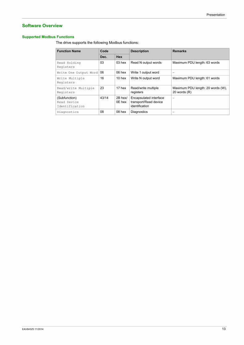
Supported Modbus FunctionsThe drive supports the following Modbus functions:
Function Name Code Description Remarks
Dec. Hex
Read Holding Registers
03 03 hex Read N output words Maximum PDU length: 63 words
Write One Output Word 06 06 hex Write 1 output word −
Write Multiple Registers
16 10 hex Write N output word Maximum PDU length: 61 words
Read/write Multiple Registers
23 17 hex Read/write multiple registers
Maximum PDU length: 20 words (W), 20 words (R)
(Subfunction) Read Device Identification
43/14 2B hex/0E hex
Encapsulated interface transport/Read device identification
−
Diagnostics 08 08 hex Diagnostics −
EAV64325 11/2014 13

Presentation
14 EAV64325 11/2014

Altivar Process BasicsEAV64325 11/2014
Basics
Chapter 2Basics
What Is in This Chapter?This chapter contains the following sections:
Section Topic Page
2.1 Profile 16
2.2 Modbus Functions 34
EAV64325 11/2014 15

Basics
Profile
Section 2.1Profile
What Is in This Section?This section contains the following topics:
Topic Page
Definition of a Profile 17
Functional Profiles Supported by the Drive 18
Functional Description 19
CIA402 Operating State Diagram 20
Description of Operating States 21
Summary 23
Control Word ( )CMd 24
Stop Commands 25
Assigning Control Word Bits 26
Status Word ( )EtA 27
Starting Sequence 28
Sequence for a Drive Powered by the Power Stage Supply 29
Sequence for a Drive with Separate Control Stage 31
Sequence for a Drive with Mains Contactor Control 33
16 EAV64325 11/2014

Basics
Definition of a Profile
Types of ProfilesThere are 3 types of profile:
Communication profilesFunctional profilesApplication profiles
Communication ProfileA communication profile describes the characteristics of the bus or network:
CablesConnectorsElectrical characteristicsAccess protocolAddressing systemPeriodic exchange serviceMessaging service...
A communication profile is unique to a type of fieldbus (such as Modbus, PROFIBUS DP, and so on) and is used by various different types of device.
Functional ProfileA functional profile describes the behavior of a type of device:
FunctionsParameters (such as name, format, unit, type, and so on.)Periodic I/O variablesState chart...
A functional profile is common to all members of a device family (such as variable speed drives, encoders, I/O modules, displays, and so on).
They can feature common or similar parts. The standardized (IEC 61800-7) functional profiles of variable speed drives are:
CiA402PROFIDRIVECIP
DRIVECOM has been available since 1991.
CiA402 device profile for drives and motion control represents the next stage of this standard development and is now part of the IEC 61800-7 standard.
Some protocols also support the Open DeviceNet Vendor Association profile (ODVA).
Application ProfileApplication profile defines the services to be provided by the devices on a machine. For example, CiA DSP 417-2 V 1.01 part 2: CANopen application profile for lift control systems - virtual device definitions.
InterchangeabilityThe aim of communication and functional profiles is to achieve interchangeability of the devices connected via the fieldbus.
EAV64325 11/2014 17

Basics
Functional Profiles Supported by the Drive
I/O ProfileUsing the I/O profile simplifies PLC programming.
The I/O profile mirrors the use of the terminal strip for control by utilizing 1 bit to control a function.
The I/O profile for the drive can also be used when controlling via a fieldbus.The drive starts up as soon as the run command is sent.15 bits of the control word (bits 1...15) can be assigned to a specific function.
This profile can be developed for simultaneous control of the drive via:The terminalsThe Modbus control wordThe CANopen control wordEthernet Modbus TCP embeddedThe fieldbus module control word
The I/O profile is supported by the drive itself and therefore in turn by all the communication ports (integrated Modbus, CANopen, Ethernet, PROFIBUS DP ,PROFINET, and DeviceNet fieldbus modules).
CiA402 ProfileThe drive only starts up following a command sequence.
The control word is standardized.
5 bits of the control word (bits 11...15) can be assigned to a function.
The CiA402 profile is supported by the drive itself and therefore by all the communication ports (Modbus, CANopen, Ethernet, PROFIBUS DP, PROFINET, and DeviceNet).
The drive supports the velocity mode of CiA402 profile.
In the CiA402 profile, there are two modes that are specific to the drive and characterize commands and references value management:
Separate [Separate] (SEP)Not separate [Not separ.] (SIN),
18 EAV64325 11/2014

Basics
Functional Description
IntroductionDrive operation involves two main functions, which are illustrated in the diagrams below.
CiA402The main parameters are shown with their CiA402 name and their CiA402/Drivecom index (the values in brackets are the CANopen addresses of the parameter).
The following figure shows the control diagram for drive operation:
Simplified diagram for speed control in Velocity mode:
Altivar DriveThese diagrams translate as follows for the Altivar drive.
The following figure shows the control diagram for drive operation:
Simplified diagram for speed control in Velocity mode:
EAV64325 11/2014 19
Basics
CIA402 Operating State Diagram
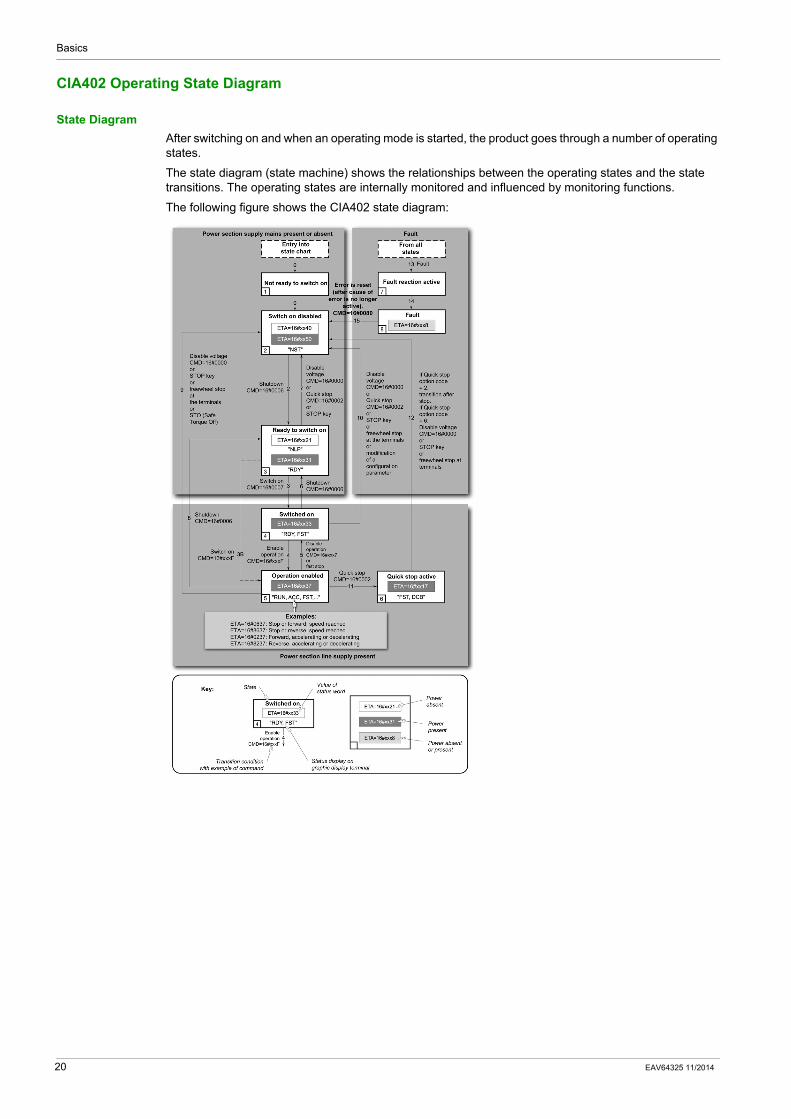
State DiagramAfter switching on and when an operating mode is started, the product goes through a number of operating states.
The state diagram (state machine) shows the relationships between the operating states and the state transitions. The operating states are internally monitored and influenced by monitoring functions.
The following figure shows the CIA402 state diagram:
20 EAV64325 11/2014

Basics
Description of Operating States
Drive Operating StateThe operating state of the drive changes depending on whether the control word is sent ( ) CMd or an event occurs (an error detection, for example).
The drive operating state can be identified by the value of the status word ( )EtA .
Operating State Description
1 - Not ready to switch on
Initialization starts. This is a transient state invisible to the communication network.
2 - Switch on disabled The power stage is not ready to switch on.The drive is locked, no power is supplied to the motor.For a separate control stage, it is not necessary to supply the power.For a separate control stage with mains contactor, the contactor is not closed.The configuration and adjustment parameters can be modified.
3 - Ready to switch on The power stage is ready to switch on and awaiting power stage supply mains.For a separate control stage, it is not necessary to supply the power stage, but the system expects it in order to change to state 4 - Switched on.For a separate control stage with mains contactor, the contactor is not closed.The drive is locked, no power is supplied to the motor.The configuration and adjustment parameters can be modified.
4 - Switched on Power stage is switched on.For a separate control stage, the power stage must be supplied.For a separate control stage with mains contactor, the contactor is closed.The drive is locked, no power is supplied to the motor.The power stage of the drive is ready to operate, but voltage has not yet been applied to the output.The adjustment parameters can be modified.If a configuration parameter is modified, the drive returns to the state 2 - Switch on disable .
EAV64325 11/2014 21

Basics
5 - Operation enabled Power stage is enabled. The drive is in running stateFor a separate control stage, the power stage must be supplied.For a separate control stage with mains contactor, the contactor is closed.The drive is unlocked, power is supplied to the motor.The drive functions are activated and voltage is applied to the motor terminals.If the reference value is zero or the Halt command is applied, no power is supplied to the motor and no torque is applied. To perform.[Auto tuning] ( ) tUn , the drive must be in state 5 - Operation enabled. The adjustment parameters can be modified.The configuration parameters cannot be modified.
NOTE: The command 4 - Enable operation must be taken into consideration only if the channel is valid. In particular, if the channel is involved in the command and the reference value, transition 4 is possible only after the reference value has been received once.
The reaction of the drive to a Disable operation command depends on the value of the [Dis. operat opt code] ( )dOtd parameter:
If the [Dis. operat opt code] ( )dOtd parameter is set to 0, the drive changes to operating state 4 - Switched on and stops in freewheel stop.If the [Dis. operat opt code] ( )dOtd parameter is set to 1, the drive stops on ramp and then changes to operating state 4 - Switched on.
6 - Quick stop active The drive performs a fast stop and remains locked in the operating state 6-Quick stop active. Before restarting the motor, it is required to go to the operating state 2-switch on disabled.During fast stop, the drive is unlocked and power is supplied to the motor.The configuration parameters cannot be modified.The condition for transition 12 to state 2 - Switch on disabled depends on the value of the parameterQuick stop mode (QStd):If the Quick stop mode parameter has the value FST2, the drive stops according to the fast stop ramp and then changes to state 2 - Switch on disabled .If the Quick stop mode parameter has the value FST6, the drive stops according to the fast stop ramp and then remains in state 6 - Quick stop active until:
A Disable voltage command is received orThe STOP key is pressed orA freewheel stop command via the digital input of the terminal.
7 - Fault reaction active
Transient state during which the drive performs an action corresponding to the selected error response.
8 - Fault Error response terminated. Power stage is disabled.The drive is locked, no power is supplied to the motor.
Operating State Description
22 EAV64325 11/2014
Basics
Summary
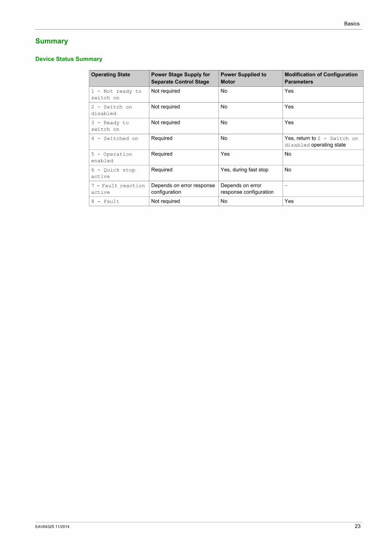
Device Status Summary
Operating State Power Stage Supply for Separate Control Stage
Power Supplied to Motor
Modification of Configuration Parameters
1 - Not ready to switch on
Not required No Yes
2 - Switch on disabled
Not required No Yes
3 - Ready to switch on
Not required No Yes
4 - Switched on Required No Yes, return to 2 - Switch on disabled operating state
5 - Operation enabled
Required Yes No
6 - Quick stop active
Required Yes, during fast stop No
7 - Fault reaction active
Depends on error response configuration
Depends on error response configuration
−
8 - Fault Not required No Yes
EAV64325 11/2014 23
Basics
Control Word ( )CMd
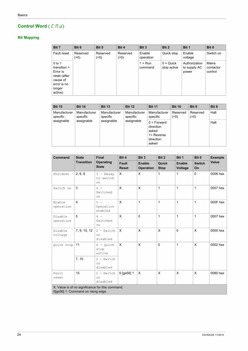
Bit Mapping
Bit 7 Bit 6 Bit 5 Bit 4 Bit 3 Bit 2 Bit 1 Bit 0
Fault reset Reserved (=0)
Reserved (=0)
Reserved (=0)
Enable operation
Quick stop Enable voltage
Switch on
0 to 1 transition = Error is reset (after cause of error is no longer active)
1 = Run command
0 = Quick stop active
Authorization to supply AC power
Mains contactor control
Bit 15 Bit 14 Bit 13 Bit 12 Bit 11 Bit 10 Bit 9 Bit 8
Manufacturer specific assignable
Manufacturer specific assignable
Manufacturer specific assignable
Manufacturer specific assignable
Manufacturer specific
Reserved (=0)
Reserved (=0)
Halt
0 = Forward direction asked 1= Reverse direction asked
Halt
Command State Transition
Final Operating State
Bit 4 Bit 3 Bit 2 Bit 1 Bit 0 Example ValueFault
ResetEnable Operation
Quick Stop
Enable Voltage
Switch On
Shutdown 2, 6, 8 3 - Ready to switch on
X X 1 1 0 0006 hex
Switch on 3 4 - Switched on
X X 1 1 1 0007 hex
Enable operation
4 5 - Operation enabled
X 1 1 1 1 000F hex
Disable operation
5 4 - Switched on
X 0 1 1 1 0007 hex
Disable voltage
7, 9, 10, 12 2 - Switch on disabled
X X X 0 X 0000 hex
Quick stop 11 6 - Quick stop active
X X 0 1 X 0002 hex
7, 10 2 - Switch on disabled
Fault reset
15 2 - Switch on disabled
0 [gs56] 1 X X X X 0080 hex
X: Value is of no significance for this command.0[gs56] 1: Command on rising edge.
24 EAV64325 11/2014

Basics
Stop Commands
Halt CommandThe Halt command enables movement to be interrupted without having to leave the 5 - Operation enabled state. The stop is performed in accordance with the [Type of stop] ( )Stt parameter.
If the Halt command is active, no power is supplied to the motor and no torque is applied.
Regardless of the assignment of the [Type of stop] ( )Stt parameter [Fast stop assign] ( )FSt ,[Ramp stop] ( )rMP , [Freewheel] ( )nSt , or [DC injection assign.] ( )dCI ), the drive remains in the 5 - Operation enabled state.
Fast Stop CommandA Fast Stop command at the terminals or using a bit of the control word assigned to Fast Stop causes a change to the 4 - Switched on
Freewheel CommandA Freewheel Stop command using a digital input of the terminal or a bit of the control word assigned to Freewheel Stop causes a change to operating state 2 - Switch on disabled.
EAV64325 11/2014 25

Basics
Assigning Control Word Bits
Function CodesIn the CiA402 profile, fixed assignment of a function input is possible using the following codes:
For example, to assign the DC injection braking to bit13 of Modbus serial, simply configure the[ DC injection assign.] ( )dCI parameter with the [C113] ( ) C113 value.
Bit 11 is assigned by default to the operating direction command [Reverse assign.] ( )rrS .
Bit Integrated Modbus Serial
Bit 11 C111
Bit 12 C112
Bit 13 C113
Bit 14 C114
Bit 15 C115
26 EAV64325 11/2014

Basics
Status Word ( )EtA
Bit Mapping
Bit 7 Bit 6 Bit 5 Bit 4 Bit 3 Bit 2 Bit 1 Bit 0
Warning Switch on disabled
Quick stop Voltage enabled
Detected error
Operation enabled
Switched on Ready to switch on
A warning is active
Power stage supply disabled
0 = Quick stop is active
Power stage supply present
Detected error
Running Ready 1 = Awaiting power Stage supply
Bit 15 Bit 14 Bit 13 Bit 12 Bit 11 Bit 10 Bit 9 Bit 8
Manufacturer-specific Direction of rotation
Manufacturer-specific Stop via STOP key
Reserved (=0)
Reserved (=0)
Internal limit active
Target reached
Remote Reserved (=0)
Reference value outside limits
Reference value reached
Command or reference value via fieldbus
Operating State
Bit 6 Bit 5 Bit 4 Bit 3 Bit 2 Bit 1 Bit 0 ETA Masked by 006F H (1)
Switch On Disabled
Quick Stop
Voltage Enabled
Fault Operation Enabled
Switched On
Ready to Switch On
1 -Not ready to switch on
0 X X 0 0 0 0 −
2 -Switch on disabled
1 X X 0 0 0 0 0040 hex
3 -Ready to switch on
0 1 X 0 0 0 1 0021 hex
4 -Switched on
0 1 1 0 0 1 1 0023 hex
5 -Operation enabled
0 1 11 0 1 1 1 0027 hex
6 -Quick stop active
0 0 0 1 1 1 0007 hex
7 -Fault reaction active
0 X X 1 1 1 1 −
8 -Fault 0 X X 1 0 0 0 0008 hex(2)...0028 hex
(1) This mask can be used by the PLC program to test the diagram state.(2) detected error following operating state 6 - Quick stop active.X: In this state, the value of the bit can be 0 or 1.
EAV64325 11/2014 27

Basics
Starting Sequence
DescriptionThe command sequence in the state diagram depends on how power is being supplied to the drive.
There are 3 possible scenarios:
Power stage supply
Direct Direct Mains contactor controlled by the drive
Control stage supply
Not separate (1) Separate Separate
(1) The power stage supplies the control stage.
28 EAV64325 11/2014

Basics
Sequence for a Drive Powered by the Power Stage Supply
DescriptionBoth the power and control stages are powered by the power stage supply.
If power is supplied to the control stage, it has to be supplied to the power stage as well.
The following sequence must be applied:
Step 1Apply the 2 - Shut down command
Step 2Check that the drive is in the operating state 3 - Ready to switch on.Then apply the 4 - Enable operation command.The motor can be controlled (send a reference value not equal to zero).
EAV64325 11/2014 29

Basics
NOTE: It is possible, but not necessary to apply the 3 - Switch on command followed by the 4 - Enable Operation command to switch successively into the operating states 3 - Ready to Switch on, 4 - Switched on and then 5 - Operation Enabled. The 4 - Enable operation command is sufficient.
30 EAV64325 11/2014

Basics
Sequence for a Drive with Separate Control Stage
DescriptionPower is supplied separately to the power and control stages.
If power is supplied to the control stage, it does not have to be supplied to the power stage as well.
The following sequence must be applied:
Step 1The power stage supply is not necessarily present.Apply the 2 - Shut down command
Step 2Check that the drive is in the operating state 3 - Ready to switch on.Check that the power stage supply is present (Voltage enabled of the status word).
Apply the 3 - Switch on command
Power Stage Supply Terminal Display Status Word
Absent nLP 21 hex
Present rdY 31 hex
EAV64325 11/2014 31

Basics
Step 3Check that the drive is in the operating state 4 - Switched on.Then apply the 4 - Enable operation command.The motor can be controlled (send a reference value not equal to zero).If the power stage supply is still not present in the operating state 4 - Switched on after a time delay [Mains V. time out] ( )LCt , the drive triggers an error [input contactor] ( )LCF .
32 EAV64325 11/2014

Basics
Sequence for a Drive with Mains Contactor Control
DescriptionPower is supplied separately to the power and control stages.
If power is supplied to the control stage, it does not have to be supplied to the power stage as well. The drive controls the mains contactor.
The following sequence must be applied:
Step 1The power stage supply is not present as the mains contactor is not being controlled.Apply the 2 - Shutdown command.
Step 2Check that the drive is in the operating state 3 - Ready to switch on.Apply the 3 - Switch on command, which closes the mains contactor and switch on the power stage supply.
EAV64325 11/2014 33

Basics
Modbus Functions
Section 2.2Modbus Functions
What Is in This Section?This section contains the following topics:
Topic Page
Modbus Protocol 35
Supported Modbus Functions 36
34 EAV64325 11/2014

Basics
Modbus Protocol
IntroductionThe transmission mode used is RTU. The frame does not contain message header and end of message bytes.
The data is transmitted in binary code.
CRC16: cyclical redundancy check.
The end of the frame is detected on a silence greater than or equal to three characters.
PrincipleThe Modbus protocol is a master/slave protocol
Only one device can transmit on the line at any time.
The master manages the exchanges and only it can take the initiative.
It interrogates each of the slaves in succession
No slave can send a message unless it is invited to do so.
The master repeats the question when there is an incorrect exchange, and declares the interrogated slave absent if no response is received within a given time period.
If a slave does not understand a message, it sends an exception response to the master. The master may or may not repeat the request.
Direct slave-to-slave communications are not possible.
For slave-to-slave communication, the application software must therefore be designed to interrogate a slave and send back data received to the other slave.
The 2 types of dialogue are possible between master and slaves:The master sends a request to a slave and waits for its responseThe master sends a request to all slaves without waiting for a response (broadcasting principle)
AddressesAddress specification:
The drive Modbus address can be configured from 1 to 247.Address 0 coded in a request sent by the master is reserved for broadcasting. Drives take account of the request, but do not respond to it.
Slave address Request code Data CRC16
EAV64325 11/2014 35

Basics
Supported Modbus Functions
IntroductionThe drive supports the following Modbus functions:
Read Holding RegistersRequest
Response
Request
For example:
This function can be used to read all drive words, both input words and output words.
Request
Response
Function Name Code Description Remarks
Dec. Hex
Read Holding Registers 03 03 hex Read N output words Maximum PDU length: 63 words
Write One Output Word 06 06 hex Write 1 output word −
Write Multiple Registers
16 10 hex Write N output word Maximum PDU length: 61 words
Read/write Multiple Registers
23 17 hex Read/write multiple registers
Maximum PDU length: 20 words (W), 20 words (R)
(Subfunction) Read Device Identification
43/14 2B hex/0E hex
Encapsulated interface transport/Read device identification
−
Diagnostics 08 08 hex Diagnostics −
Function code 1 byte 03 hex
Starting address 2 bytes 0000 hex...FFFF hex
Quantity of registers 2 bytes 1...63 (3F hex)
Function code 1 byte 03 hex
Byte count 1 byte 2 x N(1)
Register value N(1) x 2 bytes −
(1) N: Quantity of registers
Detected error code 1 byte 83 hex
Exception code 1 bytes 01...04
Slave no. 03 No. of first word No. of words CRC16
Hi Lo Hi Lo Lo Hi
1 byte 1 byte 2 bytes 2 bytes 2 bytes
Hi = high-order byte, Lo = low-order byte.
Slave no. 03 Number of bytes read First word value Last word value CRC16
Hi Lo Hi Lo Lo Hi
1 byte 1 byte 1 byte 2 bytes 2 bytes 2 bytes
Hi = high-order byte, Lo = low-order byte.
36 EAV64325 11/2014

Basics
For example: read 4 words W3102...W3105 (0C1E...0C21 hex) in slave 2, using function 3, where:SFr = Switching frequency = 4 kHz (W3102 = 0028 hex)tFr = Maximum output frequency = 60 Hz (W3103 = 0258 hex)HSP = High speed = 50 Hz (W3104 = 01F4 hex)LSP = Low speed = 0 Hz (W3105 = 0000 hex)
Request
Response
Write 1 Output WordRequest
Response
Detected error
For exampleRequest and response(the frame format is identical)
For example: write value 000D hex in word W9001 (2329 hex) in slave 2 (ACC = 1.3 s).
02 03 0C1E 004 276C
02 03 08 0028 0258 01F4 0000 52B0
Value of: − W3102 W3103 W3104 W3105 −
Parameters: − SFr tFr HSP LSP −
Function code 1 byte 06 hex
Register address 2 bytes 0000 hex...FFFF hex
Register value 2 bytes 0000 hex...FFFF hex
Function code 1 byte 06 hex
Register address 2 bytes 0000 H...FFFF hex
Register value 2 bytes 0000 H...FFFF hex
Detected error code 1 byte 06 hex
Exception code 1 bytes 01...04
Slave no. 06 Word number Value of word CRC16
Hi Lo Hi Lo Lo Hi
1 byte 1 byte 2 bytes 2 bytes 2 bytes
Request and response 02 06 2329 000D 9270
EAV64325 11/2014 37

Basics
Write Multiple RegisterRequest
Response
For exampleWrite values 20 and 30 to words W9001 and W9002 on slave 2 (acceleration time = 2 s and deceleration time = 3 s)
Request
Response
Read/Write Multiple Registers
For example
Slave no. 10 No. of first word Number of words Number of bytes
Value of first word CRC16
Hi Lo Hi Lo Hi Lo Lo Hi
1 byte 1 byte 2 bytes 2 bytes 1 byte 2 bytes 2 bytes
Slave no. 10 No. of first word No. of words CRC16
Hi Lo Hi Lo Lo Hi
1 byte 1 byte 2 bytes 2 bytes 2 bytes
Slave no.
Request code
No. of first word
Number of words
Number of bytes
Value of first word
Value of Second word
CRC16
Hi Lo Hi Lo Hi Lo Hi Lo Lo Hi
02 hex 10 hex 23 hex
29 hex
00 hex
02 hex
04 hex 00 hex
14 hex
00 hex 1E hex 73 hex A4 hex
Slave no. Response code No. of first word No. of words CRC16
Hi Lo Hi Lo Lo Hi
02 hex 10 hex 23 hex 29 hex 00 hex 02 hex 9B hex B7 hex
Description Length in Byte Value Comment
Function code 1 17 hex −
Read starting address 2 XXXX hex Always Modbus address
Quantity 2 03 hex Contain number of holding registers to be read
Write starting address 2 XXXX hex Always Modbus address
Quantity 2 03 hex Contain number of holding registers to be written
Write byte count 1 06 hex The byte count specifies the number of bytes to follow in the field write register value
Write registers value 6 XXXXXX XXXXXX hex
Value to be written respectively in NCA1 to NCA3, so the configured For example: CMD, LFRD, CMI
38 EAV64325 11/2014

Basics
Read Device IdentificationThe table provides the device identification details:
For exampleDefault value to be detailed
Request
Response
The total response size equals 49 bytes
The three objects contained in the response correspond to the following objects:Object number 1: Manufacturer name (always Schneider Electric, that is. 18 bytes).Object number 2: Device reference (ASCII string; for example, ATV6xxxxxxxx, that is. 11 bytes).Object number 3: Device version, in MMmm format where MM represents the determinant and mm the subdeterminant (4-bytes ASCII string; for example,: 0201 for version 2.1).
NOTE: The response to function 43 may be negative; in this case, the response located at the top of the next page is sent by the rather than the response described above.
ID Name / Description Type
00 hex VendorName ASCII String
01 hex ProductCode ASCII String
02 hex MajorMinorRevision ASCII String
03 hex ProductName ASCII String
Slave no. 2B Type of MEI0E
Read Device Id01
Object Id00
CRC16
Lo Hi
1 byte 1 byte 1 byte 1 byte 1 byte 2 bytes
Slave no. 2B Type of MEI0E
Read Device Id01
Degree of conformity02
1 byte 1 byte 1 byte 1 byte 1 byte
Number of additional frames00
Next object Id00
Number of objects03
1 byte 1 byte 1 byte
Id of object number 100
Length of object number 112
Value of object number 1Schneider Electric
1 byte 1 byte 18 bytes
Id of object number 201
Length of object number 20B
Value of object number 2ATV6xxxxxxxx
1 byte 1 byte 11 bytes
Id of object number 202
Length of object number 204
Value of object number 20201
1 byte 1 byte 4 bytes
CRC16
Lo Hi
1 byte 1 byte
EAV64325 11/2014 39

Basics
DiagnosticsSubcode 00 hex: EchoThis function asks the slave being interrogated to echo (return) the message sent by the master in its entirety.
Subcode 0A hex: Counter resetThis function resets all the counters responsible for monitoring a slave exchanges.
Subcode 0C hex: Read message counter responsible for counting messages received with checksum errors.
Subcode 0E hex: Read message counter responsible for counting messages addressed to slave. Read a word indicating the total number of messages addressed to the slave, regardless of type (excluding broadcast messages).
Request and response
For example: values 31 hex and 32 hex echoed by slave 4.
Request and response
Slave no. 08 Subcode Data CRC16
Hi Lo Hi Lo Lo Hi
1 byte 1 byte 2 bytes N bytes 2 bytes
Subcode Request Data Response Data Function Executed
00 XX YY XX YY Echo
0A 00 00 00 00 Counter reset
0C 00 00 XX YY(= counter value)
Read message counter responsible for counting messages received with checksum errors
0E 00 00 XX YY(= counter value)
Read message counter responsible for counting messages addressed to slave
Slave no. Request code or response code
Subcode Value of first byte
Value of second byte
CRC16
Hi Lo Lo Hi
02 hex 08 hex 00 hex 00 hex 31 hex 32 hex 74 hex 1B hex
40 EAV64325 11/2014

Altivar Process Hardware SetupEAV64325 11/2014
Hardware Setup
Chapter 3Hardware Setup
What Is in This Chapter?This chapter contains the following topics:
Topic Page
Hardware Presentation 42
Firmware Version 43
Connection to the Adapter 44
Electrical Installation 45
Cable Routing Practices 47
Accessories Presentation 48
EAV64325 11/2014 41
Hardware Setup
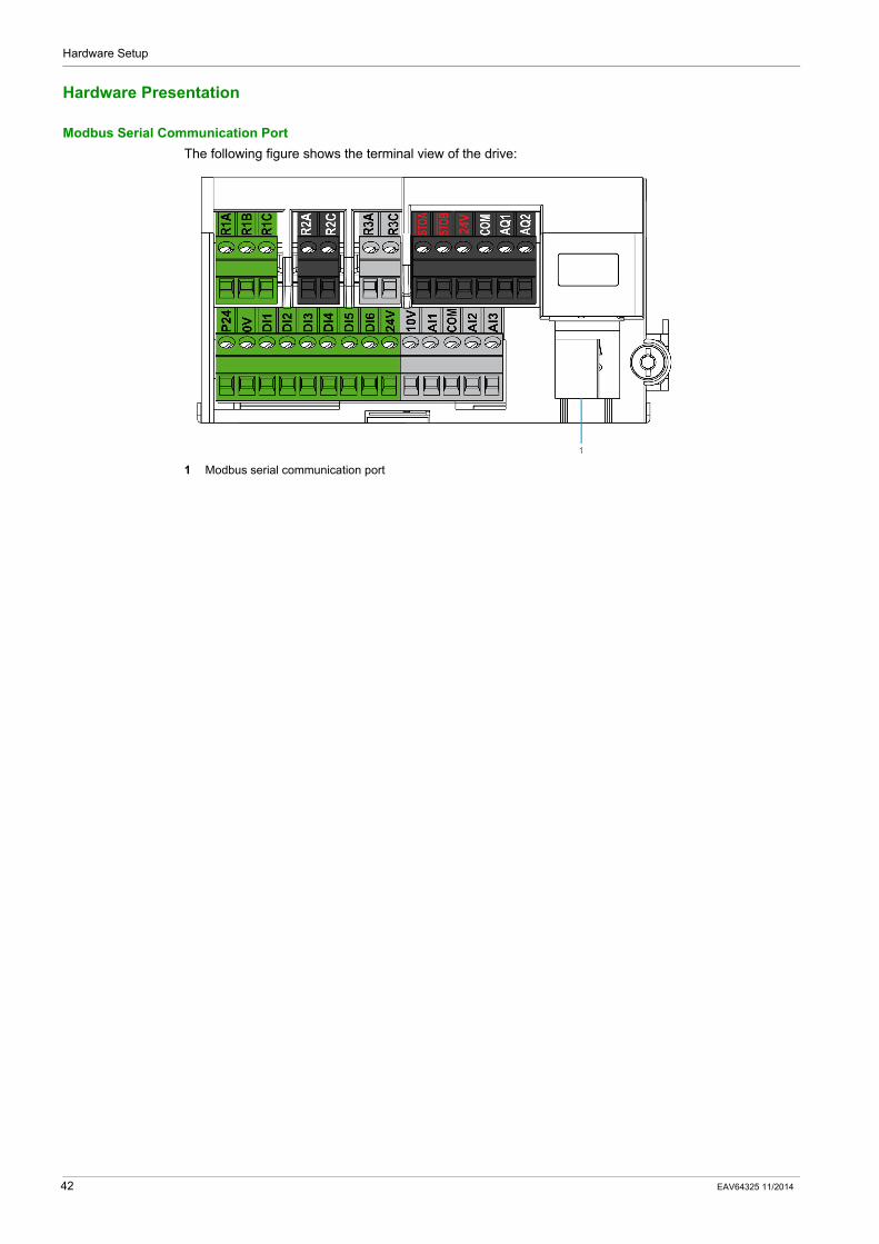
Hardware Presentation
Modbus Serial Communication PortThe following figure shows the terminal view of the drive:
1 Modbus serial communication port
42 EAV64325 11/2014

Hardware Setup
Firmware Version
CompatibilityThere is no specific firmware for Modbus serial communication. The drive firmware embeds the Modbus serial firmware.
EAV64325 11/2014 43

Hardware Setup
Connection to the Adapter
Procedure to Remove the Front Cover of the Drive
Apply the following instructions to remove the front cover of the drive:
Step Action
1 Unscrew the four screws attaching the front cover
2 Slide down the front cover
3 Remove the front cover
4 Plug the Modbus serial cable in the Modbus serial port
44 EAV64325 11/2014

Hardware Setup
Electrical Installation
Connection to DriveConnection accessories should be ordered separately (See the catalog for more details).
Connect the RJ45 cable connector to the drive connector.
The following figure shows the pin layout for RJ45 connector:
The table describes the pin out of the RJ45 connector of the drive:
RS485 Bus SchematicThe RS485 standard allows variants of different characteristics:
PolarizationLine terminatorDistribution of a reference potentialNumber of slavesLength of bus
The new Modbus specification published on the Modbus.org site in 2006 contains precise details of all these characteristics. They are also summarized in standard schematic section. The new Schneider Electric devices conform to this specification.
Pin Signal
1 Reserved
2
3
4 D1(1)
5 D0(1)
6 −
7 VP, 10 Vdc(2)
8 Common(1) Modbus signals(2) Supply for RS232 / RS485 converter or a remote terminal
EAV64325 11/2014 45

Hardware Setup
Schematic DiagramThe following is the RS485 bus schematic diagram:
Characteristic Definition
Type of trunk cable Shielded cable with 1 twisted pair and at least a third conductor
Maximum length of bus 1000 m at 19200 bps with the Schneider Electric TSX CSA••• cable
Maximum number of stations (without repeater)
32 stations that are 31 slaves
Maximum length of tap links 20 m for 1 tape link40 m divided by the number of tape links on a multiple junction box
Bus polarization One 450...650 Ω pull-down resistor at 5 V (650 Ω recommended)One 450...650 Ω pull-down resistor at the common (650 Ω recommended)
This polarization is recommended for the master.
Line terminator One 120 Ω 0.25 W resistor in series with 1 nF 10 V capacitor
Common polarity Yes (Common), connected to the protective earth ground at one or more points of the bus
46 EAV64325 11/2014

Hardware Setup
Cable Routing Practices
Protection Against InterferenceUse the Schneider Electric cable with 2 pairs of shielded twisted conductors (reference: TSXCSA100, TSXCSA200, and TSXCSA500).Keep the Modbus cable separated from the power cables (30 cm (11.8 in.) minimum).Make any crossovers of the Modbus cable and the power cables at right-angles, if necessary.
EAV64325 11/2014 47

Hardware Setup
Accessories Presentation
IntroductionConnection accessories should be ordered separately (See the catalogs).
48 EAV64325 11/2014

Altivar Process Software SetupEAV64325 11/2014
Software Setup
Chapter 4Software Setup
What Is in This Chapter?This chapter contains the following sections:
Section Topic Page
4.1 Basic Settings 50
4.2 Additional Settings 56
4.3 Monitoring the Communication Scanner 74
4.4 Fieldbus Integration Using Unity 92
EAV64325 11/2014 49

Software Setup
Basic Settings
Section 4.1Basic Settings
What Is in This Section?This section contains the following topics:
Topic Page
Configuring the Communication Parameters 51
[Modbus Address] (Add) 52
[Modbus baud rate] (tbr) 53
[Modbus format] (tFO) 54
[Modbus Time Out] (tto) 55
50 EAV64325 11/2014

Software Setup
Configuring the Communication Parameters
OverviewConfiguration of the Modbus communication functions of the drive can be accessed from the [Communication] (COM-) / [Comm parameters] (CMP-) / [Modbus SL] (MSL-) menu.
EAV64325 11/2014 51

Software Setup
[Modbus Address] (Add)
About This ParameterThis parameter defines the address of the drive on the network.
AccessThis is a read/write parameter.
The parameter Modbus address is 6001
Possible SettingsThe table presents the parameter settings:
Settings Code Value Description
[OFF][1 to 247]
(OFF)(1...247)
01...247
Modbus address is not assigned.Modbus address is assigned.Factory setting: OFF
52 EAV64325 11/2014

Software Setup
[Modbus baud rate] (tbr)
About This ParameterThis parameter defines the baud rate at which data is transferred.
AccessThis is a read/write parameter.
The parameter Modbus address is 6003
Possible SettingsThe table presents the parameter settings:
Settings Code Value Description
[4K8][9K6][19K2][38K4]
(4K8)(9K6)(19K2)(38K4)
24283236
Baud rate is set to 4.8 Kbps.Baud rate is set to 9.6 Kbps.Baud rate is set to 19.2 Kbps.Baud rate is set to 38.4 Kbps.Factory setting: 19.2 Kbps
EAV64325 11/2014 53

Software Setup
[Modbus format] (tFO)
About This ParameterThis parameter is used to define the data format.
AccessThis is a read/write parameter.
The parameter Modbus address is 6004
Possible SettingsThis table presents the parameter settings:
Settings Code Value Description
[8O1][8E1][8N1][8N2]
(8O1)(8E1)(8N1)(8N2)
2345
8 data bits, odd parity, 1 stop bit8 data bits, even parity, 1 stop bit8 data bits, no parity, 1 stop bit8 data bits, no parity, 2 stop bitsFactory setting: 8E1
54 EAV64325 11/2014

Software Setup
[Modbus Time Out] (tto)
About This ParameterThis parameter defines.
AccessThis is a read/write parameter.
The parameter Modbus address is 6005
Possible SettingsThe table presents the parameter settings:
Settings Code Value Description
[0.1...30.0] (0.1...30.0) 1...300 Adjustable from 0.1 to 30 sFactory setting: 10 s
EAV64325 11/2014 55

Software Setup
Additional Settings
Section 4.2Additional Settings
What Is in This Section?This section contains the following topics:
Topic Page
Local Configuration of the Communication Scanner 57
[Scan.IN1 address] (nMA1) 58
[Scan.IN2 address] (nMA2) 59
[Scan.IN3 address] (nMA3) 60
[Scan.IN4 address] (nMA4) 61
[Scan.IN5 address] (nMA5) 62
[Scan.IN6 address] (nMA6) 63
[Scan.IN7 address] (nMA7) 64
[Scan.IN8 address] (nMA8) 65
[Scan.Out1 address] (nCA1) 66
[Scan.Out2 address] (nCA2) 67
[Scan.Out3 address] (nCA3) 68
[Scan.Out4 address] (nCA4) 69
[Scan.Out5 address] (nCA5) 70
[Scan.Out6 address] (nCA6) 71
[Scan.Out7 address] (nCA7) 72
[Scan.Out8 address] (nCA8) 73
56 EAV64325 11/2014

Software Setup
Local Configuration of the Communication Scanner
OverviewThe communication scanner is useful when used in combination by the Modbus client device with the function Read/Write Multiple registers: 23 (17 hex), which provides in a single telegram a read multiple registers and a write multiple registers. The detail of the function 23 is described in the supported Modbus functions.
The communication scanner is accessible via the following menus: Communication (COM-)/ Comm parameters (CMP-)/ Modbus SL (MSL-)/ Modbus Fieldbus (Md1-) and [COM. SCANNER INPUT] (ICS-), [COM. SCANNER OUTPUT] (OCS-) submenus.
The eight output variables and the eight input variables are assigned to parameter nCA1 to nCA8 and nMA1 to nMA8. An nCAx or nMAx parameter with a value of zero is not linked to a parameter in the drive.
EAV64325 11/2014 57

Software Setup
[Scan.IN1 address] (nMA1)
About This ParameterThis parameter displays the source drive address of the first input word.
AccessThis is a read/write parameter.
The parameter Modbus address is 12701
Possible SettingsThe table presents the parameter settings:
Settings Code Value Description
[Scan.IN1 address] (nMA1) − Source drive address of the first input word.Factory settings: Status (ETA)
58 EAV64325 11/2014

Software Setup
[Scan.IN2 address] (nMA2)
About This ParameterThis parameter displays the source drive address of the second input word.
AccessThis is a read/write parameter.
The parameter Modbus address is 12702
Possible SettingsThe table presents the parameter settings:
Settings Code Value Description
[Scan.IN2 address] (nMA2) − Source drive address of the second input word.Factory settings: Output speed (RFRD)
EAV64325 11/2014 59

Software Setup
[Scan.IN3 address] (nMA3)
About This ParameterThis parameter displays the source drive address of the third input word.
AccessThis is a read/write parameter.
The parameter Modbus address is 12703
Possible SettingsThe table presents the parameter settings:
Settings Code Value Description
[Scan.IN3 address] (nMA3) − Source drive address of the third input word.Factory settings: 0
60 EAV64325 11/2014

Software Setup
[Scan.IN4 address] (nMA4)
About This ParameterThis parameter displays the source drive address of the fourth input word.
AccessThis is a read/write parameter.
The parameter Modbus address is 12704
Possible SettingsThe table presents the parameter settings:
Settings Code Value Description
[Scan.IN4 address] (nMA4) − Source drive address of the fourth input word.Factory settings: 0
EAV64325 11/2014 61

Software Setup
[Scan.IN5 address] (nMA5)
About This ParameterThis parameter displays the source drive address of the fifth input word.
AccessThis is a read/write parameter.
The parameter Modbus address is 12705
Possible SettingsThe table presents the parameter settings:
Settings Code Value Description
[Scan.IN5 address] (nMA5) − Source drive address of the fifth input word.Factory settings: 0
62 EAV64325 11/2014

Software Setup
[Scan.IN6 address] (nMA6)
About This ParameterThis parameter displays the source drive address of the sixth input word.
AccessThis is a read/write parameter.
The parameter Modbus address is 12706.
Possible SettingsThe table presents the parameter settings:
Settings Code Value Description
[Scan.IN6 address] (nMA6) − Source drive address of the sixth input word.Factory settings: 0
EAV64325 11/2014 63

Software Setup
[Scan.IN7 address] (nMA7)
About This ParameterThis parameter displays the source drive address of the seventh input word.
AccessThis is a read/write parameter.
The parameter Modbus address is 12707
Possible SettingsThe table presents the parameter settings:
Settings Code Value Description
[Scan.IN7 address] (nMA7) − Source drive address of the seventh input word.Factory settings: 0
64 EAV64325 11/2014

Software Setup
[Scan.IN8 address] (nMA8)
About This ParameterThis parameter displays the source drive address of the eighth input word.
AccessThis is a read/write parameter.
The parameter Modbus address is 12708.
Possible SettingsThe table presents the parameter settings:
Settings Code Value Description
[Scan.IN8 address] (nMA8) − Source drive address of the eighth input word.Factory settings: 0
EAV64325 11/2014 65

Software Setup
[Scan.Out1 address] (nCA1)
About This ParameterThis parameter displays the destination drive address of the first output word.
AccessThis is a read/write parameter.
The parameter Modbus address is 12721.
Possible SettingsThe table presents the parameter settings:
Settings Code Value Description
[Scan.Out1 address] (nCA1) − Destination drive address of the first output word.Factory settings: Command (CMD)
66 EAV64325 11/2014

Software Setup
[Scan.Out2 address] (nCA2)
About This ParameterThis parameter displays the destination drive address of the second output word.
AccessThis is a read/write parameter.
The parameter Modbus address is 12722.
Possible SettingsThe table presents the parameter settings:
Settings Code Value Description
[Scan.Out2 address] (nCA2) − Destination drive address of the second output word.Factory settings: Speed target (LFRD)
EAV64325 11/2014 67

Software Setup
[Scan.Out3 address] (nCA3)
About This ParameterThis parameter displays the destination drive address of the third output word.
AccessThis is a read/write parameter.
The parameter Modbus address is 12723.
Possible SettingsThe table presents the parameter settings:
Settings Code Value Description
[Scan.Out3 address] (nCA3) − Destination drive address of the third output word.Factory settings: 0
68 EAV64325 11/2014

Software Setup
[Scan.Out4 address] (nCA4)
About This ParameterThis parameter displays the destination drive address of the fourth output word.
AccessThis is a read/write parameter.
The parameter Modbus address is 12724.
Possible SettingsThe table presents the parameter settings:
Settings Code Value Description
[Scan.Out4 address] (nCA4) − Destination drive address of the fourth output word.Factory settings: 0
EAV64325 11/2014 69

Software Setup
[Scan.Out5 address] (nCA5)
About This ParameterThis parameter displays the destination drive address of the fifth output word.
AccessThis is a read/write parameter.
The parameter Modbus address is 12725.
Possible SettingsThe table presents the parameter settings:
Settings Code Value Description
[Scan.Out5 address] (nCA5) − Destination drive address of the fifth output word.Factory settings: 0
70 EAV64325 11/2014

Software Setup
[Scan.Out6 address] (nCA6)
About This ParameterThis parameter displays the destination drive address of the sixth output word.
AccessThis is a read/write parameter.
The parameter Modbus address is 12726.
Possible SettingsThe table presents the parameter settings:
Settings Code Value Description
[Scan.Out6 address] (nCA6) − Destination drive address of the sixth output word.Factory settings: 0
EAV64325 11/2014 71

Software Setup
[Scan.Out7 address] (nCA7)
About This ParameterThis parameter displays the destination drive address of the seventh output word.
AccessThis is a read/write parameter.
The parameter Modbus address is 12727.
Possible SettingsThe table presents the parameter settings:
Settings Code Value Description
[Scan.Out7 address] (nCA7) − Destination drive address of the seventh output word.Factory settings: 0
72 EAV64325 11/2014

Software Setup
[Scan.Out8 address] (nCA8)
About This ParameterThis parameter displays the destination drive address of the eight output word.
AccessThis is a read/write parameter.
The parameter Modbus address is 12728.
Possible SettingsThe table presents the parameter settings:
Settings Code Value Description
[Scan.Out8 address] (nCA8) − Destination drive address of the 8 output word.Factory settings: 0
EAV64325 11/2014 73

Software Setup
Monitoring the Communication Scanner
Section 4.3Monitoring the Communication Scanner
What Is in This Section?This section contains the following topics:
Topic Page
Introduction 75
[Com Scan.In1 val.] (nM1) 76
[Com Scan.In2 val.] (nM2) 77
[Com Scan.In3 val.] (nM3) 78
[Com Scan.In4 val.] (nM4) 79
[Com Scan.In5 val.] (nM5) 80
[Com Scan.In6 val.] (nM6) 81
[Com Scan.In7 val.] (nM7) 82
[Com Scan.In8 val.] (nM8) 83
[Com Scan.Out1 val.] (nC1) 84
[Com Scan.Out2 val.] (nC2) 85
[Com Scan.Out3 val.] (nC3) 86
[Com Scan.Out4 val.] (nC4) 87
[Com Scan.Out5 val.] (nC5) 88
[Com Scan.Out6 val.] (nC6) 89
[Com Scan.Out7 val.] (nC7) 90
[Com Scan.Out8 val.] (nC8) 91
74 EAV64325 11/2014

Software Setup
Introduction
OverviewIt is also possible to monitor the value of the parameters which has been configured in the communication scanner.This monitored values are accessible via the following menus: [Display] (MOn-
)/[Communication map] (CMM-)[Modbus network diag] (Mnd-) and [COM. SCANNER INPUT MAP] (ISA-), [COM SCAN OUTPUT MAP] (OSA-) submenu.
The 8 output variable values and the 8 input variable values are located into parameters [Com Scan Out1 val.] (nC1) to [Com Scan Out8 val.] (nC8) and [Com Scan In1 val.] (nM1) to [Com Scan In8 val.] (nM8).
EAV64325 11/2014 75

Software Setup
[Com Scan.In1 val.] (nM1)
About This ParameterThis parameter displays the source drive value of the first input word.
AccessThis is a read/write parameter.
The parameter Modbus address is 12741.
Possible SettingsThe table presents the parameter settings:
Settings Code Value Description
[Com Scan.In1 Val.] (nM1) − Source drive value of the first input word.Factory settings: ETA value
76 EAV64325 11/2014

Software Setup
[Com Scan.In2 val.] (nM2)
About This ParameterThis parameter displays the source drive value of the second input word.
AccessThis is a read/write parameter.
The parameter Modbus address is 12742.
Possible SettingsThe table presents the parameter settings:
Settings Code Value Description
[Com Scan.In2 Val.] (nM2) − Source drive value of the second input wordFactory settings: RFRD value
EAV64325 11/2014 77

Software Setup
[Com Scan.In3 val.] (nM3)
About This ParameterThis parameter displays the source drive value of the third input word.
AccessThis is a read/write parameter.
The parameter Modbus address is 12743 .
Possible SettingsThe table presents the parameter settings:
Settings Code Value Description
[Com Scan.In3 Val.] (nM3) − Source drive value of the third input wordFactory settings: 0
78 EAV64325 11/2014

Software Setup
[Com Scan.In4 val.] (nM4)
About This ParameterThis parameter displays the source drive value of the fourth input word.
AccessThis is a read/write parameter.
The parameter Modbus address is 12744.
Possible SettingsThe table presents the parameter settings:
Settings Code Value Description
[Com Scan.In4 Val.] (nM4) − Source drive value of the fourth input word.Factory settings: 0
EAV64325 11/2014 79

Software Setup
[Com Scan.In5 val.] (nM5)
About This ParameterThis parameter displays the source drive value of the fifth input word.
AccessThis is a read/write parameter.
The parameter Modbus address is 12745.
Possible SettingsThe table presents the parameter settings:
Settings Code Value Description
[Com Scan.In5 Val.] (nM5) − Source drive value of the fifth input word.Factory settings: 0
80 EAV64325 11/2014

Software Setup
[Com Scan.In6 val.] (nM6)
About This ParameterThis parameter displays the source drive value of the sixth input word.
AccessThis is a read/write parameter.
The parameter Modbus address is 12746.
Possible SettingsThe table presents the parameter settings:
Settings Code Value Description
[Com Scan.In6 Val.] (nM6) − Source drive value of the sixth input word Factory settings: 0
EAV64325 11/2014 81

Software Setup
[Com Scan.In7 val.] (nM7)
About This ParameterThis parameter displays the source drive value of the seventh input word.
AccessThis is a read/write parameter.
The parameter Modbus address is 12747.
Possible SettingsThe table presents the parameter settings:
Settings Code Value Description
[Com Scan.In7 Val.] (nM7) − Source drive value of the seventh input word.Factory settings: 0
82 EAV64325 11/2014

Software Setup
[Com Scan.In8 val.] (nM8)
About This ParameterThis parameter displays the source drive value of the eighth input word.
AccessThis is a read/write parameter.
The parameter Modbus address is 12748.
Possible SettingsThe table presents the parameter settings:
Settings Code Value Description
[Com Scan.In8 Val.] (nM8) − Source drive value of the eighth input word.Factory settings: 0
EAV64325 11/2014 83

Software Setup
[Com Scan.Out1 val.] (nC1)
About This ParameterThis parameter displays the destination drive value of the first output word.
AccessThis is a read/write parameter.
The parameter Modbus address is 12761.
Possible SettingsThe table presents the parameter settings:
Settings Code Value Description
[Com Scan.Out1 Val.] (nC1) − Destination drive value of the first output word.Factory settings: CMD value
84 EAV64325 11/2014

Software Setup
[Com Scan.Out2 val.] (nC2)
About This ParameterThis parameter displays the destination drive value of the second output word.
AccessThis is a read/write parameter.
The parameter Modbus address is 12762.
Possible SettingsThe table presents the parameter settings:
Settings Code Value Description
[Com Scan.Out2 Val.] (nC2) − Destination drive value of the second output wordFactory settings: LFRD value
EAV64325 11/2014 85

Software Setup
[Com Scan.Out3 val.] (nC3)
About This ParameterThis parameter displays the destination drive value of the third output word.
AccessThis is a read/write parameter.
The parameter Modbus address is 12763.
Possible SettingsThe table presents the parameter settings:
Settings Code Value Description
[Com Scan.Out3 Val.] (nC3) − Destination drive value of the third output word.Factory settings: 0
86 EAV64325 11/2014

Software Setup
[Com Scan.Out4 val.] (nC4)
About This ParameterThis parameter displays the destination drive value of the fourth output word.
AccessThis is a read/write parameter.
The parameter Modbus address is 12764.
Possible SettingsThe table presents the parameter settings:
Settings Code Value Description
[Com Scan.Out4 Val.] (nC4) − Destination drive value of the fourth output word.Factory settings: 0
EAV64325 11/2014 87

Software Setup
[Com Scan.Out5 val.] (nC5)
About This ParameterThis parameter displays the destination drive value of the fifth output word.
AccessThis is a read/write parameter.
The parameter Modbus address is 12765.
Possible SettingsThe table presents the parameter settings:
Settings Code Value Description
[Com Scan.Out5 Val.] (nC5) − Destination drive value of the fifth output word.Factory settings: 0
88 EAV64325 11/2014

Software Setup
[Com Scan.Out6 val.] (nC6)
About This ParameterThis parameter displays the destination drive value of the sixth output word.
AccessThis is a read/write parameter.
The parameter Modbus address is 12766.
Possible SettingsThe table presents the parameter settings:
Settings Code Value Description
[Com Scan.Out6 Val.] (nC6) − Destination drive value of the sixth output word.Factory settings: 0
EAV64325 11/2014 89

Software Setup
[Com Scan.Out7 val.] (nC7)
About This ParameterThis parameter displays the destination drive value of the seventh output word.
AccessThis is a read/write parameter.
The parameter Modbus address is 12767.
Possible SettingsThe table presents the parameter settings:
Settings Code Value Description
[Com Scan.Out7 Val.] (nC7) − Destination drive value of the seventh output word.Factory settings: 0
90 EAV64325 11/2014

Software Setup
[Com Scan.Out8 val.] (nC8)
About This ParameterThis parameter displays the destination drive value of the eighth output word.
AccessThis is a read/write parameter.
The parameter Modbus address is 12768.
Possible SettingsThe table presents the parameter settings:
Settings Code Value Description
[Com Scan.Out8 Val.] (nC8) − Destination drive value of the eighth output word.Factory settings: 0
EAV64325 11/2014 91

Software Setup
Fieldbus Integration Using Unity
Section 4.4Fieldbus Integration Using Unity
What Is in This Section?This section contains the following topics:
Topic Page
Introduction 93
Drive Configuration 94
Modbus Master Configuration 95
92 EAV64325 11/2014

Software Setup
Introduction
OverviewHere is an example of an application that shows how to control a drive with a M340 PLC equipped with a Modbus master serial port. The operator can control the drive directly from Unity. The version of Unity used here is Unity Pro XL
In the example, the communication scanner of the drive is used. The PLC sends the command and the reference speed to the drive and read the status word and the actual speed of the drive.
EAV64325 11/2014 93

Software Setup
Drive Configuration
Factory SettingBefore configuring the drive, it is advised to make a factory setting. Go to:
[File management] (FMt-) menu,[Factory settings] (FCS-) submenu.
Then configure the following parameters:[Parameter group list] (FrY-) = [All] (All)[Go to Factory Settings] (GFS) = OK
Command ConfigurationTo control the drive with a Modbus master, it is necessary to select Modbus as command channel active.
Goto to:[Complete Settings] (CSt-)[Command and Reference] (CrP-) menu
Then configure:[Ref.1 channel] (Fr1) parameter to [Ref. Freq-Modbus] (Mdb) value.
Communication ConfigurationSelect the Modbus address in the menu:
[Communication] (COM-)[Comm parameters] (CMP-)[Modbus SL] (MSL-)[Modbus Fieldbus] (Md1-)[Modbus Address] (Add)
The drive must be restarted in order to take into account the Modbus address.
94 EAV64325 11/2014

Software Setup
Modbus Master Configuration
OverviewIn this example, Modbus master configuration is done with unity.
Serial Port ConfigurationConfigure the serial port as master. The other default settings are compliant with the default settings of the drive.
Data Structure DeclarationCreate the following table (DevicePath). DevicePath describes the path to the device including its slave address.
EAV64325 11/2014 95

Software Setup
Then create the four other tables as arrays from 0 to 3 of integer.
As all the tables declared are dynamic (no fixed address), it is necessary in the project setting to «Allows dynamic array» and to «Directly represented array variables». The parameterization must be done in the menu «Tool», «Project settings», «Language extensions» window.
96 EAV64325 11/2014
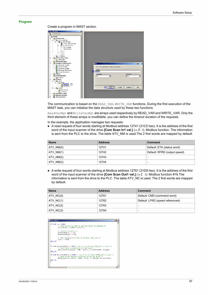
Software Setup
ProgramCreate a program in MAST section.
The communication is based on the READ_VAR, WRITE_VAR functions. During the first execution of the MAST task, you can initialize the data structure used by these two functions.
ReadVarMgt and WriteVarMgt are arrays used respectively by READ_VAR and WRITE_VAR. Only the third element of these arrays is modifiable, you can define the timeout duration of the requests.
In the example, the application manages two requests:A read request of four words starting at Modbus address 12741 (31C5 hex). It is the address of the first word of the input scanner of the drive [Com Scan In1 val.] (nM1). Modbus function. The information is sent from the PLC to the drive. The table ATV_NM is used.The 2 first words are mapped by default.
A write request of four words starting at Modbus address 12761 (31D9 hex). It is the address of the first word of the input scanner of the drive [Com Scan Out1 val.] (nC1). Modbus function #16.The information is sent from the drive to the PLC. The table ATV_NC is used. The 2 first words are mapped by default.
Name Address Comment
ATV_NM(0) 12741 Default: ETA (status word)
ATV_NM(1) 12742 Default: RFRD (output speed)
ATV_NM(2) 12743 −
ATV_NM(3) 12744 −
Name Address Comment
ATV_NC(0) 12761 Default: CMD (command word)
ATV_NC(1) 12762 Default: LFRD (speed referenced)
ATV_NC(2) 12763 −
ATV_NC(3) 12764 −
EAV64325 11/2014 97

Software Setup
98 EAV64325 11/2014

Altivar Process OperationsEAV64325 11/2014
Operations
Chapter 5Operations
What Is in This Chapter?This chapter contains the following sections:
Section Topic Page
5.1 Operating States 100
5.2 Operating Modes 101
EAV64325 11/2014 99

Operations
Operating States
Section 5.1Operating States
Configuring Communication Detected Error Response
DescriptionThe response of the drive in the event of a Modbus serial communication interruption can be configured. Configuration can be performed using the display terminal from the [Complete settings] (CSt-), [Error/warning handling] (CSWM) menu, [Fieldbus monitoring] ( )CLL- submenu, via the [Modbus Error Resp] ( )SLL .
The values of the [Modbus Error Resp] ( )SLL parameter, which triggers a drive detected error [Modbus Com Interruption] (SLF1), are:
The values of the [Modbus Error Resp] ( )SLL parameter, which does not trigger a drive detected error, are:
Value Meaning
[Freewheel] (YES) Freewheel stop (factory setting)
[Ramp stop] (rMP) Stop on ramp
[Fast stop] ( )FSt Fast stop
[DC injection] ( )dCI DC injection stop
Value Meaning
[Ignore] (nO) Detected error ignored
[Per STT] (Stt) Stop according to configuration of [Type of stop] (Stt)
[fallback spd] (LFF) Change to fallback speed, maintained as long as the detected error persists and the run command has not been removed.The fallback speed can be configured in the [Complete settings] (CSt-), [Error/warning handling] (CSWM) menu, [Fallback speed] ( )LFF- submenu, using the [Fallback speed] (LFF) parameter.
[Spd maint.] (rLS) The drive maintains the speed at the time the detected error occurred, as long as the detected error persists, and the run command has not been removed
WARNINGLOSS OF CONTROLIf this parameter is set to nO, Modbus communication monitoring is disabled.
Only use this setting after a thorough risk assessment in compliance with all regulations and standards that apply to the device and to the application.Only use this setting for tests during commissioning.Verify that communication monitoring has been re-enabled before completing the commissioning procedure and performing the final commissioning test.
Failure to follow these instructions can result in death, serious injury, or equipment damage.
100 EAV64325 11/2014

Operations
Operating Modes
Section 5.2Operating Modes
What Is in This Section?This section contains the following topics:
Topic Page
Configuring the Control Channel 102
Configuration of the Drive for Operation in I/O Profile 103
Configuration of the Drive for Operation with CiA 402 Profile in Combined Mode 104
Configuration of the Drive for Operation with CiA 402 Profile in Separate Mode 105
EAV64325 11/2014 101

Operations
Configuring the Control Channel
OverviewThis chapter explains how to configure the drive for operation from communication network through three following examples.
I/O mode - a simple command word (based on forward, reverse, and reset binary commands).Combined mode (with native profile CiA 402) - Both reference value and command word come from the communication network.Separate (with native profile CiA 402) - reference value and command come from separate sources: for example, the command (in CiA 402) comes from the communication network and the reference value from the HMI.
102 EAV64325 11/2014

Operations
Configuration of the Drive for Operation in I/O Profile
DescriptionThe I/O profile, here is a simple example, which can be extended with additional features. The command word is made of run forward (bit 0 of CMd), run reverse (bit 1 of CMd), and the function fault reset (bit 7 of CMd).
The settings are the following:
The bits of the command word can now be configured.
In the [Command and Reference] ( )CrP- menu configure:
In the [Error/warning handling] ( )CSWM menu, [Fault Reset] ( ) rSt- submenu, configure:
[Ref.1 channel] (Fr1) [HMI] (HMI)
[Reverse Disable] (rIn) Default
[Stop Key Enable] (PSt) Default
[Profile] (CHCF) [I/O profile] IO
[Cmd switching] (CCS) Default
[Cmd channel 1] (Cd1) [Modbus] (Mdb)
[Reverse assign.] (rrS [Cd01] (Cd01)
[Fault Reset Assign] (rSF) [Cd07] (Cd07)
EAV64325 11/2014 103

Operations
Configuration of the Drive for Operation with CiA 402 Profile in Combined Mode
DescriptionThis section describes how to configure the settings of the drive if it is controlled in CiA 402 mode. The example focuses on the not separate mode. Additional modes are detailed in the drive programming manual.
In the [Complete settings] ( ) CSt- menu, [Command and reference] ( )CrP- submenu:):[Ref.1 Channel] (Fr1): is set on according to the communication source you can choose in the following table:
[Profile] (CHCF): defines if the drive operates in combined mode (reference value and command from the same channel).
Origin of the Control Ref1 Channel Setting
Modbus serial [Modbus] (Mdb)
104 EAV64325 11/2014

Operations
Configuration of the Drive for Operation with CiA 402 Profile in Separate Mode
DescriptionAlternate combinations are possible, see the drive programming manual for the list of possible settings.
For example:
The drive is controlled from the communication (Modbus serial) but the reference value is adjusted on display terminal. The control word comes from the controller and is written according to CiA 402 profile.
The settings are as shown in the table:
[Ref.1 channel] (Fr1) [HMI] (LCC)
[Reverse Disable] (rIn) Default
[Stop Key Enable] (PSt) Default
[Profile] (CHCF) [Separate] (SEp)
[Cmd switching] (CCS) Default
[Cmd channel 1] (Cd1) [Modbus] Mbd
EAV64325 11/2014 105

Operations
106 EAV64325 11/2014

Altivar Process Diagnostics and TroubleshootingEAV64325 11/2014
Diagnostics and Troubleshooting
Chapter 6Diagnostics and Troubleshooting
What Is in This Chapter?This chapter contains the following topics:
Topic Page
Fieldbus Status LEDs 108
Checking Connections 110
Fieldbus Function Test 111
Communication Interruption Message 112
EAV64325 11/2014 107

Diagnostics and Troubleshooting
Fieldbus Status LEDs
LED IndicatorsThe following figure describes the LEDs status for fieldbus monitoring:
LED Description
LED COM : Link ActivityThe table provides the LED status for Modbus serial connection
Communication DiagnosticsThese parameters are visible only with the graphic display terminal.
On the terminal, in the [Display] (MOn-) menu ([COMMUNICATION MAP] (CMM-) [Modbus network diag] (Mnd-) submenu):
Item LED Description
1 COM Indicates the Modbus serial link connection status
Color & Status Description
OFF No link
Yellow flashing Fieldbus active
108 EAV64325 11/2014

Diagnostics and Troubleshooting
Modbus Counters[Mdb Frame Nb.] ( )M1Ct indicate the number of Modbus frames received. The counter counts both correct and incorrect frames.[Mb NET CRC errors] ( ) M1EC indicate the number of Modbus frames containing checksum errors.
In the case of these two counters, only frames that are destined for the drive and whose Modbus address is supplied by the [Modbus Address] ( )Add parameter are counted. Broadcast frames are not counted.
[Mdb Frame Nb.] ( ) M1Ct is modulo 65 536 counters, that is, the value is reset to zero once the value of 65 535 is reached.
By contrast, the [Mb NET CRC errors] ( )M1EC remain at 65 535 once this value is reached.
Each Modbus counter corresponds to a drive parameter:
Modbus Communication StateThis can be accessed from the menu:
[Communication] ( )COM- / [Comm parameters] ( )CMP- / [Modbus SL] (MSL-) / [Modbus Fieldbus] (Md1-) / [Mdb com stat] ( )COM1
( )r0t0 : Modbus no reception, no transmission = communication idle
( )r0t1 : Modbus no reception, transmission
( )r1t0 : Modbus reception, no transmission
( )r1t1 : Modbus reception and transmission
Menu Parameter Name Code Logical Address
[Modbus network diag] ( )Mnd- [Mdb Frame Nb.] ( )M1Ct 6011
[Mb NET CRC errors] ( )M1EC 6010
EAV64325 11/2014 109

Diagnostics and Troubleshooting
Checking Connections
DescriptionIf the product cannot be addressed using the fieldbus, verify that
The connector is plugged in correctly.The wires are correctly connected to connector(if possible).The ends of line resistors are connected on both sides of the complete network.The ends of line resistors have the good values.The wiring of the all devices on the network is consistent.
110 EAV64325 11/2014

Diagnostics and Troubleshooting
Fieldbus Function Test
Command and Reference ChannelsAll the drive command and reference parameters are managed on a channel-by-channel basis.
Parameter Name Parameter Code
Taken Into Account by the Drive
Modbus Serial
CANopen Fieldbus Module Ethernet Embedded
Control word ( )CMd ( )CMd1 ( )CMd2 ( )CMd3 ( )CMd5
Extended control word ( )CMI ( )CMI1 ( )CMI2 ( )CMI3 ( )CMI5
Reference speed (rpm) ( )LFrd ( )LFrd1 ( )LFrd2 ( )LFrd3 ( )LFrd5
Reference frequency (0.1 Hz)
( )LFr ( )LFr1 ( )LFr2 ( )LFr3 ( )LFr5
Reference value supplied by PI controller
( )PISP ( )PIr1 ( )PIr2 ( )PIr3 ( )PIr5
Reference value supplied by analog multiplier function
( )MFr ( )MFr1 ( )MFr2 ( )MFr3 ( )MFr5
EAV64325 11/2014 111

Diagnostics and Troubleshooting
Communication Interruption Message
DescriptionIf the drive does not receive any Modbus request sent to its address for a predefined time [Modbus Timeout] (ttO), a [Modbus Com Interruption] (SLF1) is triggered.
112 EAV64325 11/2014

Altivar Process GlossaryEAV64325 11/2014
Glossary
AAbbreviations
Req. = Required
Opt. = Optional
DDisplay terminal
The display terminal menus are shown in square brackets.
For example: [Communication]The codes are shown in round brackets.
For example: (CON-)
Parameter names are displayed on the display terminal in square brackets.
For example: [fallback spd]Parameter codes are displayed in round brackets.
For example: (LFF)
EError
Discrepancy between a detected (computed, measured, or signaled) value or condition and the specified or theoretically correct value or condition.
FFactory setting
Factory settings when the product is shipped
FaultFault is an operating state. If the monitoring functions detect an error, a transition to this operating state is triggered, depending on the error class. A "Fault reset" is required to exit this operating state after the cause of the detected error has been removed. Further information can be found in the pertinent standards such as IEC 61800-7, ODVA Common Industrial Protocol (CIP).
Fault ResetA function used to restore the drive to an operational state after a detected error is cleared by removing the cause of the error so that the error is no longer active.
MMonitoring function
Monitoring functions acquire a value continuously or cyclically (for example, by measuring) in order to check whether it is within permissible limits. Monitoring functions are used for error detection.
EAV64325 11/2014 113

Glossary
PParameter
Device data and values that can be read and set (to a certain extent) by the user.
PELVProtective Extra Low Voltage, low voltage with isolation. For more information: IEC 60364-4-41
PLCProgrammable logic controller
Power stageThe power stage controls the motor. The power stage generates current for controlling the motor.
QQuick Stop
The Quick Stop function can be used for fast deceleration of a movement as a response to a detected error or via a command.
WWarning
If the term is used outside the context of safety instructions, a warning alerts to a potential problem that was detected by a monitoring function. A warning does not cause a transition of the operating state.
114 EAV64325 11/2014


Altivar_Modbus_Serial_EN_EAV64325_01 11/2014