air springs - delta equipement - votre partenaire pour l ... · air springs advantages of enidine...
TRANSCRIPT
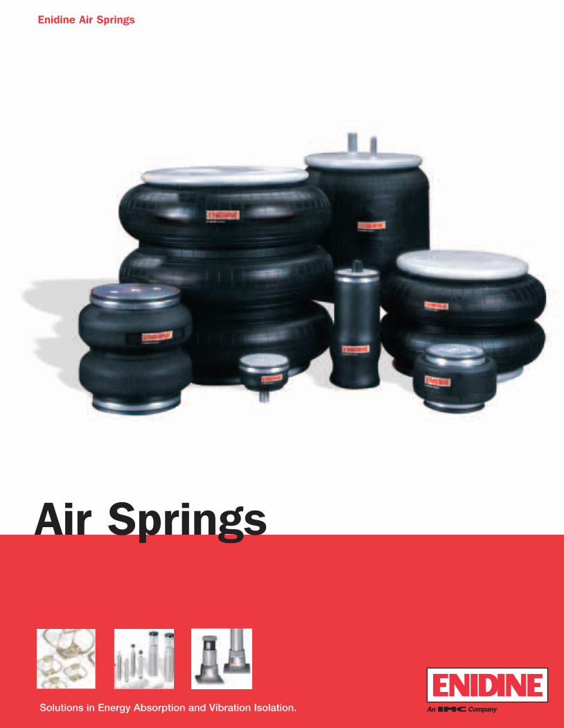
Air Springs
Enidine Air Springs
Solutions in Energy Absorption and Vibration Isolation.
Airsprings1-04-IMP-BP 2/18/04 3:14 PM Page 2
1 www.enidine.com Toll Free: 1-800-852-8508 Fax: 1-716-662-1909
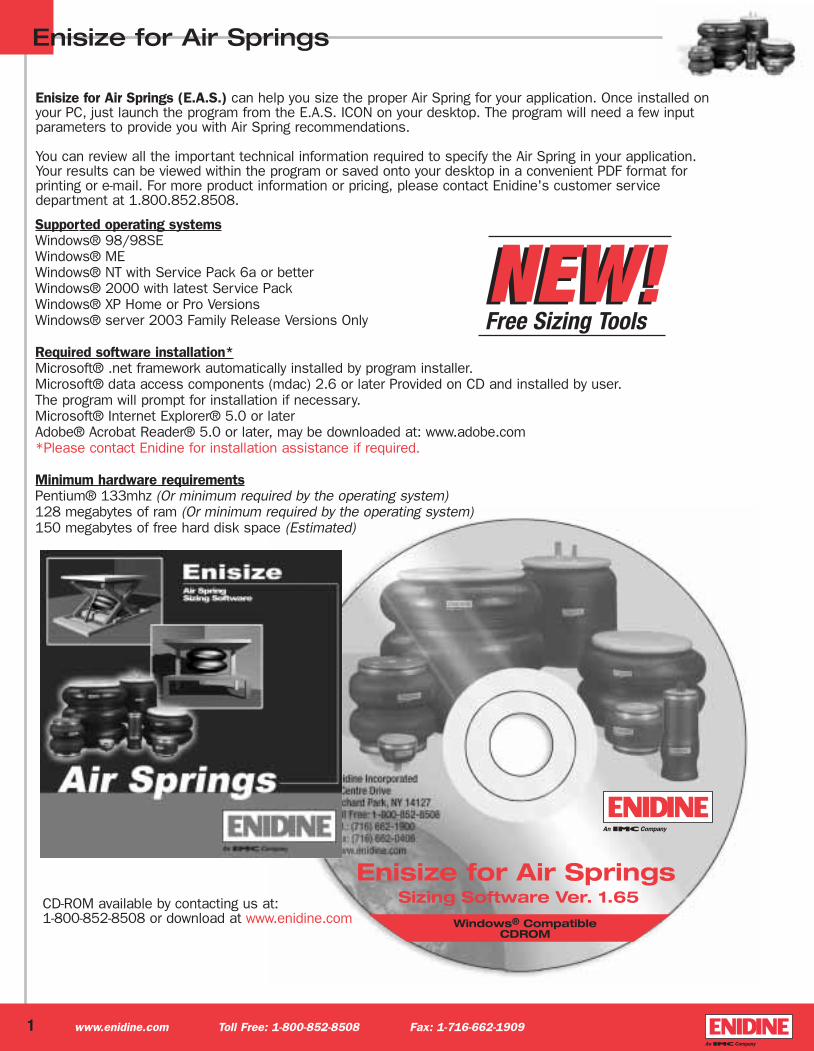
Enisize for Air Springs
Enisize for Air Springs (E.A.S.) can help you size the proper Air Spring for your application. Once installed on your PC, just launch the program from the E.A.S. ICON on your desktop. The program will need a few input parameters to provide you with Air Spring recommendations.
You can review all the important technical information required to specify the Air Spring in your application. Your results can be viewed within the program or saved onto your desktop in a convenient PDF format for printing or e-mail. For more product information or pricing, please contact Enidine's customer service department at 1.800.852.8508.
Supported operating systemsWindows® 98/98SEWindows® MEWindows® NT with Service Pack 6a or betterWindows® 2000 with latest Service PackWindows® XP Home or Pro VersionsWindows® server 2003 Family Release Versions Only
Required software installation*Microsoft® .net framework automatically installed by program installer.Microsoft® data access components (mdac) 2.6 or later Provided on CD and installed by user.The program will prompt for installation if necessary.Microsoft® Internet Explorer® 5.0 or laterAdobe® Acrobat Reader® 5.0 or later, may be downloaded at: www.adobe.com*Please contact Enidine for installation assistance if required.
Minimum hardware requirementsPentium® 133mhz (Or minimum required by the operating system)128 megabytes of ram (Or minimum required by the operating system)150 megabytes of free hard disk space (Estimated)
NEW!NEW!Free Sizing Tools
CD-ROM available by contacting us at: 1-800-852-8508 or download at www.enidine.com
Airsprings1-04-IMP-BP 2/18/04 3:14 PM Page 3
Air Springs
Enidine Air Springs are highly durable, precisely engineered and cost-effective for use in a wide variety of actuation and vibration isolation applications. With time-tested designs, fabric-reinforced WingpreneTM or Natural Rubber flex member
construction and corrosion-protected end retainers, Enidine Air Springs provide superior quality and performance.
As an actuator, Enidine Air Springs provide linear or angular motion. These Air Springs offer a favorable stroke-to-compressed-heightratio when compared to air cylinders, and can accept a wide variety of actuation media such as air, water, nitrogen or anti-freeze.
As an isolator, Enidine Air Springs are effective in reducing the harmful effects of vibration. They can simultaneously isolate vibrationand regulate load height, as well as allow for consistent vibration isolation under varying loads.
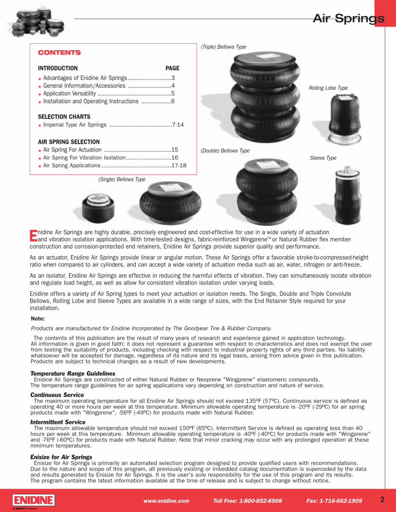
Enidine offers a variety of Air Spring types to meet your actuation or isolation needs. The Single, Double and Triple ConvoluteBellows, Rolling Lobe and Sleeve Types are available in a wide range of sizes, with the End Retainer Style required for your installation.
CONTENTS
INTRODUCTION PAGE
• Advantages of Enidine Air Springs..........................3 • General Information/Accessories ..........................4• Application Versatility ............................................5• Installation and Operating Instructions ..................6
SELECTION CHARTS• Imperial Type Air Springs ....................................7-14
AIR SPRING SELECTION• Air Spring For Actuation ........................................15• Air Spring For Vibration Isolation..........................16
• Air Spring Applications ........................................17-18
(Double) Bellows Type
(Triple) Bellows Type
Sleeve Type
Rolling Lobe Type
2
Note:
Products are manufactured for Enidine Incorporated by The Goodyear Tire & Rubber Company.
The contents of this publication are the result of many years of research and experience gained in application technology. All information is given in good faith; it does not represent a guarantee with respect to characteristics and does not exempt the userfrom testing the suitability of products, including checking with respect to industrial property rights of any third parties. No liabilitywhatsoever will be accepted for damage, regardless of its nature and its legal basis, arising from advice given in this publication.Products are subject to technical changes as a result of new developments.
Temperature Range GuidelinesEnidine Air Springs are constructed of either Natural Rubber or Neoprene "Wingprene" elastomeric compounds.
The temperature range guidelines for air spring applications vary depending on construction and nature of service.
Continuous ServiceThe maximum operating temperature for all Enidine Air Springs should not exceed 135ºF (57ºC). Continuous service is defined as
operating 40 or more hours per week at this temperature. Minimum allowable operating temperature is -20ºF (-29ºC) for air spring products made with "Wingprene", -56ºF (-49ºC) for products made with Natural Rubber.
Intermittent ServiceThe maximum allowable temperature should not exceed 150ºF (65ºC). Intermittent Service is defined as operating less than 40
hours per week at this temperature. Minimum allowable operating temperature is -40ºF (-40ºC) for products made with "Wingprene"and -76ºF (-60ºC) for products made with Natural Rubber. Note that minor cracking may occur with any prolonged operation at theseminimum temperatures.
Enisize for Air SpringsEnisize for Air Springs is primarily an automated selection program designed to provide qualified users with recommendations.
Due to the nature and scope of this program, all previously existing or imbedded catalog documentation is superceded by the dataand results generated by Enisize for Air Springs. It is the user's sole responsibility for the use of this program and its results. The program contains the latest information available at the time of release and is subject to change without notice.
www.enidine.com Toll Free: 1-800-852-8508 Fax: 1-716-662-1909
(Single) Bellows Type
Airsprings1-04-IMP-BP 2/18/04 3:14 PM Page 4
Air Springs
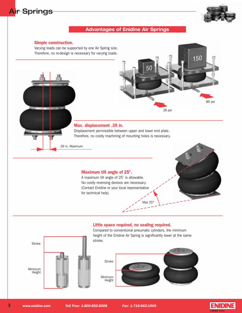
Advantages of Enidine Air Springs
Simple construction.Varying loads can be supported by one Air Spring size.Therefore, no re-design is necessary for varying loads.
Maximum tilt angle of 25°.A maximum tilt angle of 25˚ is allowable.No costly reversing devices are necessary.(Contact Enidine or your local representativefor technical help)
Max. displacement .39 in.Displacement permissible between upper and lower end plate.Therefore, no costly machining of mounting holes is necessary.
Little space required, no sealing required.Compared to conventional pneumatic cylinders, the minimumheight of the Enidine Air Spring is significantly lower at the samestroke.
28 psi
86 psi
.39 in. Maximum
Stroke
MinimumHeight
Stroke
MinimumHeight
Max 25°
3 www.enidine.com Toll Free: 1-800-852-8508 Fax: 1-716-662-1909
Airsprings1-04-IMP-BP 2/18/04 3:14 PM Page 5
Air Springs
Standard Materials Flex Members: Fabric - reinforced Wingprene
Fabric - reinforced natural rubber
End Retainers: Forged steelCast zinc alloyCast aluminum
Operating Temperature RangeFabric - reinforced Wingprene: - 40°F to 150°F
(-40°C to 65°C)Fabric - reinforced Natural Rubber: - 76°F to 150°F
(-60°C to 65°C)
Environmental ConsiderationsGood for most industrial applications. Can be affected by certain chemicals. Contact Enidine or your Local Representative for specific information.
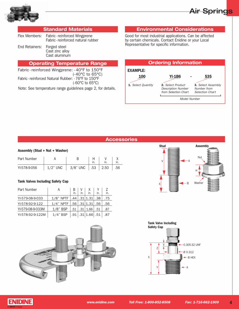
Ordering Information
Accessories
Tank Valves Including Safety Cap
Part Number A B V X Y Zin. in. in. in. in.
YI-579-08-9-033 1/8˝ NPTF .44 .31 1.31 .38 .75
YI-578-92-9-122 1/4˝ NPTF .56 .31 1.31 .56 .56
YI-579-08-9-033M 1/8˝ BSP .51 .31 1.66 .51 .87
YI-578-92-9-122M 1/4˝ BSP .91 .31 1.66 .51 .87
A
B
V
X
A
Ø 0.312
0.305-32 UNF
B HEX
Z
X
Y
V
H
AssemblyStud
Tank Valve Including Safety Cap
Assembly (Stud + Nut + Washer)
Part Number A B H V Xin. in. in.
YI-578-9-056 1/2˝ UNC 3/8˝ UNC .53 2.50 .56
Washer
Nut
Model Number
100
1. Select Quantity
YI-1B6
2. Select ProductDescription Numberfrom Selection Chart
535
3. Select AssemblyNumber from Selection Chart
EXAMPLE:
4
Note: See temperature range guidelines page 2, for details.
www.enidine.com Toll Free: 1-800-852-8508 Fax: 1-716-662-1909
Airsprings1-04-IMP-BP 2/18/04 3:14 PM Page 6

Air SpringsTypical Applications for Actuation
PressesScissor Lifts• Bin-tilting devices
• Palletizers, label applicators inpackaging equipment
• Amusement park rides
• Clutch and brake systems
• Scissor lifts
• Injection or ejection of parts in manufacturing equipment
• Vertical lift force for platforms and rotating tables
• Conveyor or transfer systems
• Rotary shaft actuators
Compressors Electronic Equipment
• Vibratory conveyors
• Large drying machines
• Centrifugal separators
• Coordinate measuring tables and machinery
• Commercial laundry machines
• Textile looms
• Conveyor loading points
• Compressors
• Electronic equipment
Typical Applications for Vibration Isolation
5
25° Maximum
www.enidine.com Toll Free: 1-800-852-8508 Fax: 1-716-662-1909
(Contact Enidine or your local representativefor technical help.)
Airsprings1-04-IMP-BP 2/18/04 3:14 PM Page 7
Air SpringsInstallation and Operating Instructions
Provide stops for minimal height,or use Air Springs with, optional Internal Bumper.
Max. allowable pressure: 100 psi (7 bar).
Provide stroke limitations,to prevent exceeding the maximum allowable stroke height.
Never use Air Springs in torsion.
above 100 psi (7 bar)Incorrect
up to 100 psi (7 bar)Correct
Incorrect
Incorrect
Incorrect
Correct
Correct
6www.enidine.com Toll Free: 1-800-852-8508 Fax: 1-716-662-1909
Airsprings1-04-IMP-BP 2/18/04 3:15 PM Page 8
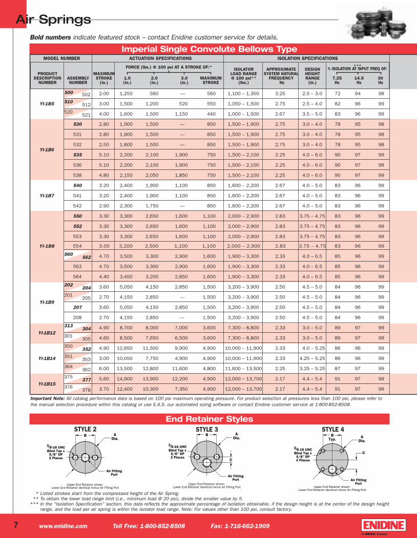
ISOLATOR APPROXIMATE DESIGNPRODUCT MAXIMUM LOAD RANGE SYSTEM NATURAL HEIGHT
DESCRIPTION ASSEMBLY STROKE 1.0 2.0 3.0 MAXIMUM @ 100 psi** FREQUENCY RANGE 7.25 14.5 30 NUMBER NUMBER (in.) (in.) (in.) (in.) STROKE (lbs.) Hz (in.) Hz Hz Hz
Air Springs
MODEL NUMBER ACTUATION SPECIFICATIONS ISOLATION SPECIFICATIONS
FORCE (lbs.) @ 100 psi AT A STROKE OF:* ***% ISOLATION AT INPUT FREQ OF:
* * Listed strokes start from the compressed height of the Air Spring.** To obtain the lower load range limit (i.e., minimum load @ 20 psi), divide the smaller value by 5.
*** In the “Isolation Specification” section, this data reflects the approximate percentage of isolation obtainable, if the design height is at the center of the design heightrange, and the load per air spring is within the isolator load range. Note: For values other than 100 psi, consult factory.
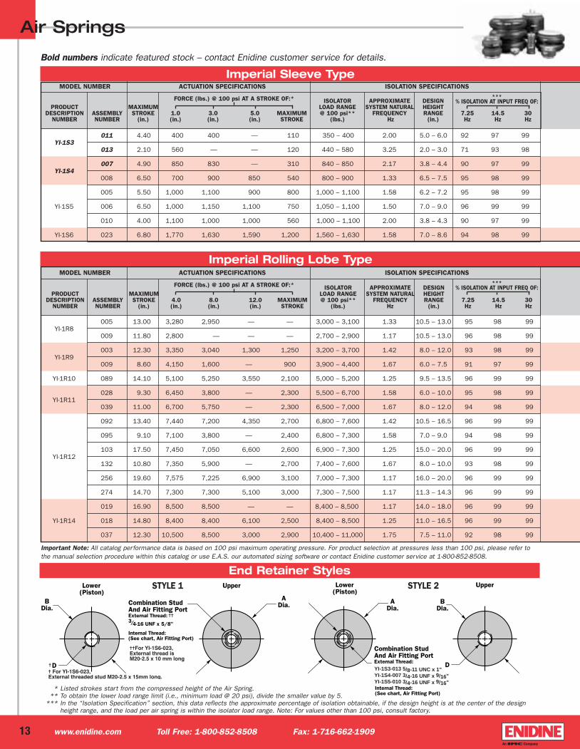
End Retainer StylesSTYLE 2 STYLE 3 STYLE 4
Imperial Single Convolute Bellows Type
7
Important Note: All catalog performance data is based on 100 psi maximum operating pressure. For product selection at pressures less than 100 psi, please refer tothe manual selection procedure within this catalog or use E.A.S. our automated sizing software or contact Enidine customer service at 1-800-852-8508.
www.enidine.com Toll Free: 1-800-852-8508 Fax: 1-716-662-1909
Bold numbers indicate featured stock – contact Enidine customer service for details.
YI-1B5
500 502 2.00 1,250 560 — 560 1,100 – 1,350 3.25 2.5 – 3.0 72 94 98
510512 3.00 1,500 1,200 520 550 1,050 – 1,500 2.75 2.5 – 4.0 82 96 99
520 521 4.00 1,600 1,500 1,150 440 1,000 – 1,500 2.67 3.5 – 5.0 83 96 99
530 2.80 1,900 1,500 — , 850 1,500 – 1,900 2.75 3.0 – 4.0 78 95 98
531 2.80 1,900 1,500 — , 850 1,500 – 1,900 2.75 3.0 – 4.0 78 95 98
YI-1B6532 2.50 1,800 1,500 — , 850 1,500 – 1,900 2.75 3.0 – 4.0 78 95 98
535 5.10 2,200 2,100 1,900 750 1,500 – 2,100 2.25 4.0 – 6.0 90 97 99
536 5.10 2,200 2,100 1,900 750 1,500 – 2,100 2.25 4.0 – 6.0 90 97 99
538 4.80 2,150 2,050 1,850 750 1,500 – 2,100 2.25 4.0 – 6.0 90 97 99
540 3.20 2,400 1,900 1,100 850 1,600 – 2,200 2.67 4.0 – 5.0 83 96 99
YI-1B7 541 3.20 2,400 1,900 1,100 850 1,600 – 2,200 2.67 4.0 – 5.0 83 96 99
542 2.90 2,300 1,750 — 850 1,600 – 2,200 2.67 4.0 – 5.0 83 96 99
550 3.30 3,300 2,650 1,600 1,100 2,000 – 2,900 2.83 3.75 – 4.75 83 96 99
552 3.30 3,300 2,650 1,600 1,100 2,000 – 2,900 2.83 3.75 – 4.75 83 96 99
553 3.30 3,300 2,650 1,600 1,100 2,000 – 2,900 2.83 3.75 – 4.75 83 96 99
YI-1B8 554 3.00 3,200 2,500 1,100 1,100 2,000 – 2,900 2.83 3.75 – 4.75 83 96 99
560562 4.70 3,500 3,300 2,900 1,600 1,900 – 3,300 2.33 4.0 – 6.5 85 96 99
563 4.70 3,500 3,300 2,900 1,600 1,900 – 3,300 2.33 4.0 – 6.5 85 96 99
564 4.40 3,450 3,200 2,850 1,600 1,900 – 3,300 2.33 4.0 – 6.5 85 96 99
202 204 3.60 5,050 4,150 2,850 1,500 3,200 – 3,900 2.50 4.5 – 5.0 84 96 99
YI-1B9
201 205 2.70 4,150 2,850 — 1,500 3,200 – 3,900 2.50 4.5 – 5.0 84 96 99
207 3.60 5,050 4,150 2,850 1,500 3,200 – 3,900 2.50 4.5 – 5.0 84 96 99
208 2.70 4,150 2,850 — 1,500 3,200 – 3,900 2.50 4.5 – 5.0 84 96 99
YI-1B12
313 304 4.90 8,700 8,000 7,000 3,600 7,300 – 8,800 2.33 3.0 – 5.0 89 97 99
301 305 4.60 8,500 7,650 6,500 3,600 7,300 – 8,800 2.33 3.0 – 5.0 89 97 99
350 352 4.90 12,650 11,500 9,900 4,900 10,000 – 11,900 2.33 4.0 – 5.25 86 96 99
YI-1B14 351 353 3.00 10,050 7,750 4,900 4,900 10,000 – 11,900 2.33 4.25 – 5.25 86 96 99
364 362 6.00 13,500 12,800 11,600 4,800 11,600 – 13,500 2.25 3.25 – 5.25 87 97 99
YI-1B15
375 377 5.60 14,900 13,900 12,200 4,900 12,000 – 13,700 2.17 4.4 – 5.4 91 97 99
376 378 3.70 12,400 10,300 7,350 4,900 12,000 – 13,700 2.17 4.4 – 5.4 91 97 99
Airsprings1-04-IMP-BP 2/18/04 3:15 PM Page 9

Air Springs
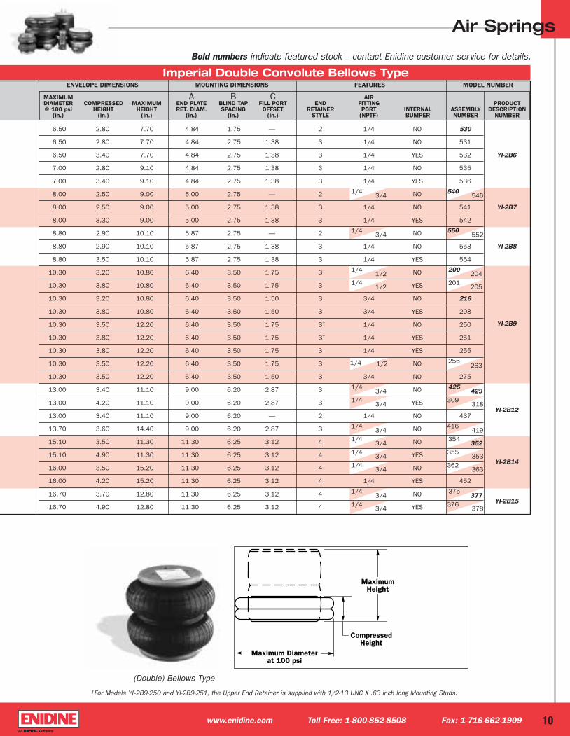
ENVELOPE DIMENSIONS MOUNTING DIMENSIONS FEATURES MODEL NUMBER
Imperial Single Convolute Bellows Type
(Single) Bellows Type
MAXIMUM A B C AIRDIAMETER COMPRESSED MAXIMUM END PLATE BLIND TAP FILL PORT END FITTING PRODUCT@ 100 psi HEIGHT HEIGHT RET. DIAM. SPACING OFFSET RETAINER PORT INTERNAL ASSEMBLY DESCRIPTION
(in.) (in.) (in.) (in.) (in.) (in.) STYLE (NPTF) BUMPER NUMBER NUMBER
8
5.70 1.80 3.80 3.40 1.75 — 2 1/4 3/4 NO 500 502
YI-1B56.00 1.80 4.80 3.40 1.75 — 2 1/4 3/4 NO 510
512
6.50 1.80 5.80 3.40 1.75 — 2 1/4 3/4 NO 520
521
6.50 2.00 4.80 4.15 1.75 — 2 1/4 NO 530
6.50 2.00 4.80 4.15 2.75 1.38 3 1/4 NO 531
6.50 2.30 4.80 4.15 2.75 1.38 3 1/4 YES 532YI-1B6
7.00 2.00 7.10 4.15 1.75 — 2 1/4 NO 535
7.00 2.00 7.10 4.15 2.75 1.38 3 1/4 NO 536
7.00 2.30 7.10 4.15 2.75 1.38 3 1/4 YES 538
7.70 2.00 5.20 4.15 1.75 — 2 1/4 NO 540
YI-1B77.70 2.00 5.20 4.15 2.75 1.38 3 1/4 NO 541
7.70 2.30 5.20 4.15 2.75 1.38 3 1/4 YES 542
8.70 2.00 5.30 5.00 2.75 — 2 1/4 NO 550
8.70 2.00 5.30 5.00 2.75 — 2 3/4 NO 552
8.70 2.00 5.30 5.00 2.75 1.38 3 1/4 NO 553
8.70 2.30 5.30 5.00 2.75 1.38 3 1/4 YES 554 YI-1B8
9.40 2.00 6.70 5.00 2.75 — 2 1/4 3/4 NO 560
562
9.40 2.00 6.70 5.00 2.75 1.38 3 1/4 NO 563
9.40 2.30 6.70 5.00 2.75 1.38 3 1/4 YES 564
11.00 2.30 5.90 6.40 3.50 1.75 3 1/4 1/2 NO 202
204
11.00 3.20 5.90 6.40 3.50 1.75 3 1/4 1/2 YES 201
205YI-1B9
11.00 2.30 5.90 6.40 3.50 1.50 3 3/4 NO 207
11.00 3.20 5.90 6.40 3.50 1.50 3 3/4 YES 208
13.20 2.30 7.20 9.00 6.20 2.87 3 1/4 3/4 NO 313
304YI-1B12
13.20 2.60 7.20 9.00 6.20 2.87 3 1/4 3/4 YES 301
305
15.20 2.30 7.20 11.30 6.25 3.12 4 1/4 3/4 NO 350
352
YI-1B1415.20 4.20 7.20 11.30 6.25 3.12 4 1/4 3/4 YES 351
353
15.90 2.30 8.30 11.30 6.25 3.12 4 1/4 3/4 NO 364
362
17.50 2.30 7.90 11.30 6.25 3.12 4 1/4 3/4 NO 375
377YI-1B15
17.50 4.20 7.90 11.30 6.25 3.12 4 1/4 3/4 YES 376
378
www.enidine.com Toll Free: 1-800-852-8508 Fax: 1-716-662-1909
Bold numbers indicate featured stock – contact Enidine customer service for details.
Airsprings1-04-IMP-BP 2/18/04 3:15 PM Page 10

ISOLATOR APPROXIMATE DESIGNPRODUCT MAXIMUM LOAD RANGE SYSTEM NATURAL HEIGHT
DESCRIPTION ASSEMBLY STROKE 2.0 4.0 6.0 MAXIMUM @ 100 psi** FREQUENCY RANGE 7.25 14.5 30 NUMBER NUMBER (in.) (in.) (in.) (in.) STROKE (lbs.) Hz (in.) Hz Hz Hz
End Retainer Styles
STYLE 2 STYLE 3 STYLE 4
Air Springs
MODEL NUMBER ACTUATION SPECIFICATIONS ISOLATION SPECIFICATIONS
FORCE (lbs.) @ 100 psi AT A STROKE OF:* ***% ISOLATION AT INPUT FREQ OF:
Imperial Double Convolute Bellows Type
* * Listed strokes start from the compressed height of the Air Spring.** To obtain the lower load range limit (i.e., minimum load @ 20 psi), divide the smaller value by 5.
*** In the “Isolation Specification” section, this data reflects the approximate percentage of isolation obtainable, if the design height is at the center of the design heightrange, and the load per air spring is within the isolator load range. Note: For values other than 100 psi, consult factory.
9
530 4.90 1,900 1,100 — 580 1,300 – 2,000 2.09 4.5 – 6.5 85 96 99
531 4.90 1,900 1,100 — 580 1,300 – 2,000 2.09 4.5 – 6.5 85 96 99
YI-2B6 532 4.30 1,700 800 — 580 1,300 – 2,000 2.09 4.5 – 6.5 85 96 99
535 6.30 2,350 1,600 700 560 1,500 – 2,200 2.09 5.0 – 7.0 92 97 99
536 5.70 2,100 1,450 700 560 1,500 – 2,200 2.09 5.0 – 7.0 92 97 99
540 546 6.50 2,900 2,300 1,250 800 1,600 – 2,500 2.08 6.0 – 8.0 91 97 99
YI-2B7 541 6.50 2,900 2,300 1,250 800 1,600 – 2,500 2.08 6.0 – 8.0 91 97 99
542 5.70 2,750 2,000 — , 800 1,600 – 2,500 2.08 6.0 – 8.0 91 97 99
550 552 7.20 3,600 2,700 1,800 1,000 2,300 – 2,700 1.92 7.0 – 8.0 93 97 99
YI-2B8 553 7.20 3,600 2,700 1,800 1,000 2,300 – 2,700 1.92 7.0 – 8.0 93 97 99
554 6.60 3,350 2,500 1,400 1,000 2,300 – 2,700 1.92 7.0 – 8.0 93 97 99
200 204 7.60 4,650 3,850 2,550 1,100 2,300 – 3,700 1.92 7.5 – 9.5 92 97 99.
201 205 7.00 4,400 3,550 2,100 1,100 2,300 – 3,700 1.92 7.5 – 9.5 92 97 99
216 7.60 4,650 3,850 2,550 1,100 2,300 – 3,700 1.92 7.5 – 9.5 92 97 99
208 7.00 4,400 3,550 2,100 1,100 2,300 – 3,700 1.92 7.5 – 9.5 92 97 99
YI-2B9 250 8.70 4,800 4,000 3,250 1,500 3,000 – 3,800 1.67 8.0 – 10.0 93 98 99
251 8.40 4,700 3,900 3,100 1,500 3,000 – 3,800 1.67 8.0 – 10.0 93 98 99
255 8.40 4,700 3,900 3,100 1,500 3,000 – 3,800 1.67 8.0 – 100 93 98 99
256 263 8.70 4,800 4,000 3,250 1,500 3,000 – 3,800 1.67 8.0 – 10.0 93 98 99
275 8.70 4,800 4,000 3,250 1,500 3,000 – 3,800 1.67 8.0 – 10.0 93 98 99
425 429 7.70 8,400 7,200 5,200 2,700 5,200 – 7,200 1.83 7.5 – 9.5 92 98 99
YI-2B12309 318 6.90 8,050 6,600 4,250 2,700 5,200 – 7,200 1.83 7.5 – 9.5 92 98 99
437 7.70 8,400 7,200 5,200 2,700 5,200 – 7,200 1.83 7.5 – 9.5 92 98 99
416 419 10.80 9,100 8,100 7,100 2,600 7,100 – 8,100 1.58 7.5 – 9.5 92 98 99
354 352 7.80 12,900 11,100 8,400 3,400 8,400 – 11,100 1.83 7.5 – 9.5 93 98 99
YI-2B14355 353 6.40 11,600 9,400 4,800 3,400 8,400 – 11,100 1.83 7.5 – 9.5 93 98 99
362 363 11.40 14,500 13,100 11,800 4,300 11,800 – 13,100 1.58 7.5 – 9.5 93 98 99
452 11.00 13,650 12,700 11,200 4,300 11,800 – 13,075 1.58 7.5 – 9.5 93 98 99
YI-2B15375 377 9.10 13,700 12,300 10,300 2,500 10,300 – 12,300 1.67 7.5 – 9.5 93 98 99
376 378 7.90 12,850 10,950 7,900 2,500 10,300 – 12,300 1.67 7.5 – 9.5 93 98 99
www.enidine.com Toll Free: 1-800-852-8508 Fax: 1-716-662-1909
Important Note: All catalog performance data is based on 100 psi maximum operating pressure. For product selection at pressures less than 100 psi, please refer tothe manual selection procedure within this catalog or use E.A.S. our automated sizing software or contact Enidine customer service at 1-800-852-8508.
Bold numbers indicate featured stock – contact Enidine customer service for details.
Airsprings1-04-IMP-BP 2/18/04 3:15 PM Page 11
Air Springs
ENVELOPE DIMENSIONS MOUNTING DIMENSIONS FEATURES MODEL NUMBER
MAXIMUM A B C AIRDIAMETER COMPRESSED MAXIMUM END PLATE BLIND TAP FILL PORT END FITTING PRODUCT@ 100 psi HEIGHT HEIGHT RET. DIAM. SPACING OFFSET RETAINER PORT INTERNAL ASSEMBLY DESCRIPTION
(in.) (in.) (in.) (in.) (in.) (in.) STYLE (NPTF) BUMPER NUMBER NUMBER
Imperial Double Convolute Bellows Type
†For Models YI -2B9-250 and YI-2B9-251, the Upper End Retainer is supplied with 1/2-13 UNC X .63 inch long Mounting Studs.
(Double) Bellows Type
10
6.50 2.80 7.70 4.84 1.75 — 2 1/4 NO 530
6.50 2.80 7.70 4.84 2.75 1.38 3 1/4 NO 531
6.50 3.40 7.70 4.84 2.75 1.38 3 1/4 YES 532 YI-2B6
7.00 2.80 9.10 4.84 2.75 1.38 3 1/4 NO 535
7.00 3.40 9.10 4.84 2.75 1.38 3 1/4 YES 536
8.00 2.50 9.00 5.00 2.75 — 2 1/4 3/4 NO 540
546
8.00 2.50 9.00 5.00 2.75 1.38 3 1/4 NO 541 YI-2B7
8.00 3.30 9.00 5.00 2.75 1.38 3 1/4 YES 542
8.80 2.90 10.10 5.87 2.75 — 2 1/4 3/4 NO 550
552
8.80 2.90 10.10 5.87 2.75 1.38 3 1/4 NO 553 YI-2B8
8.80 3.50 10.10 5.87 2.75 1.38 3 1/4 YES 554
10.30 3.20 10.80 6.40 3.50 1.75 3 1/4 1/2 NO 200
204
10.30 3.80 10.80 6.40 3.50 1.75 3 1/4 1/2 YES 201
205
10.30 3.20 10.80 6.40 3.50 1.50 3 3/4 NO 216
10.30 3.80 10.80 6.40 3.50 1.50 3 3/4 YES 208
10.30 3.50 12.20 6.40 3.50 1.75 3† 1/4 NO 250 YI-2B9
10.30 3.80 12.20 6.40 3.50 1.75 3† 1/4 YES 251
10.30 3.80 12.20 6.40 3.50 1.75 3 1/4 YES 255
10.30 3.50 12.20 6.40 3.50 1.75 3 1/4 1/2 NO 256263
10.30 3.50 12.20 6.40 3.50 1.50 3 3/4 NO 275
13.00 3.40 11.10 9.00 6.20 2.87 3 1/4 3/4 NO 425
429
13.00 4.20 11.10 9.00 6.20 2.87 3 1/4 3/4 YES 309
318YI-2B12
13.00 3.40 11.10 9.00 6.20 — 2 1/4 NO 437
13.70 3.60 14.40 9.00 6.20 2.87 3 1/4 3/4 NO 416
419
15.10 3.50 11.30 11.30 6.25 3.12 4 1/4 3/4 NO 354
352
15.10 4.90 11.30 11.30 6.25 3.12 4 1/4 3/4 YES 355
353YI-2B14
16.00 3.50 15.20 11.30 6.25 3.12 4 1/4 3/4 NO 362
363
16.00 4.20 15.20 11.30 6.25 3.12 4 1/4 YES 452
16.70 3.70 12.80 11.30 6.25 3.12 4 1/4 3/4 NO 375
377YI-2B15
16.70 4.90 12.80 11.30 6.25 3.12 4 1/4 3/4 YES 376
378
www.enidine.com Toll Free: 1-800-852-8508 Fax: 1-716-662-1909
Bold numbers indicate featured stock – contact Enidine customer service for details.
Airsprings1-04-IMP-BP 2/18/04 3:15 PM Page 12
Air Springs
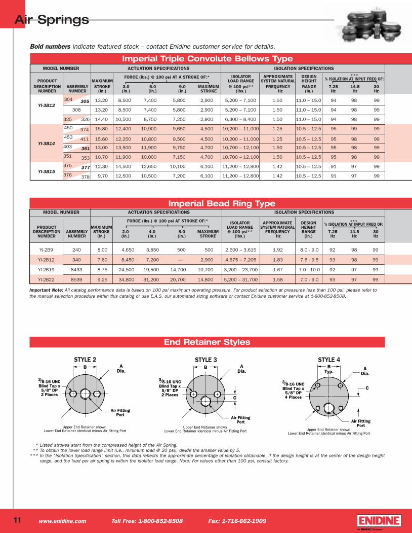
Imperial Triple Convolute Bellows Type
MODEL NUMBER ACTUATION SPECIFICATIONS ISOLATION SPECIFICATIONS
Imperial Bead Ring Type
MODEL NUMBER ACTUATION SPECIFICATIONS ISOLATION SPECIFICATIONS
ISOLATOR APPROXIMATE DESIGNPRODUCT MAXIMUM LOAD RANGE SYSTEM NATURAL HEIGHT
DESCRIPTION ASSEMBLY STROKE 3.0 6.0 9.0 MAXIMUM @ 100 psi** FREQUENCY RANGE 7.25 14.5 30 NUMBER NUMBER (in.) (in.) (in.) (in.) STROKE (lbs.) Hz (in.) Hz Hz Hz
FORCE (lbs.) @ 100 psi AT A STROKE OF:* ***% ISOLATION AT INPUT FREQ OF:
ISOLATOR APPROXIMATE DESIGNPRODUCT MAXIMUM LOAD RANGE SYSTEM NATURAL HEIGHT
DESCRIPTION ASSEMBLY STROKE 2.0 4.0 8.0 MAXIMUM @ 100 psi** FREQUENCY RANGE 7.25 14.5 30 NUMBER NUMBER (in.) (in.) (in.) (in.) STROKE (lbs.) Hz (in.) Hz Hz Hz
FORCE (lbs.) @ 100 psi AT STROKE OF:* ***% ISOLATION AT INPUT FREQ OF:
YI-2B9 240 8.00 4,650 3,850 500 500 2,600 – 3,615 1.92 8.0 - 9.0 92 98 99
YI-2B12 340 7.60 8,450 7,200 — 2,900 4,575 – 7,205 1.83 7.5 - 9.5 93 98 99
YI-2B19 8433 8.75 24,500 19,500 14,700 10,700 3,200 – 23,700 1.67 7.0 - 10.0 92 97 99
YI-2B22 8539 9.25 34,800 31,200 20,700 14,800 5,200 – 31,700 1.58 7.0 - 9.0 93 97 99
* * Listed strokes start from the compressed height of the Air Spring.** To obtain the lower load range limit (i.e., minimum load @ 20 psi), divide the smaller value by 5.
*** In the “Isolation Specification” section, this data reflects the approximate percentage of isolation obtainable, if the design height is at the center of the design heightrange, and the load per air spring is within the isolator load range. Note: For values other than 100 psi, consult factory.
End Retainer Styles
STYLE 2 STYLE 3 STYLE 4
11
YI-3B12304 305 13.20 8,500 7,400 5,800 2,900 5,200 – 7,100 1.50 11.0 – 15.0 94 98 99
308 13.20 8,500 7,400 5,800 2,900 5,200 – 7,100 1.50 11.0 – 15.0 94 98 99
325 326 14.40 10,500 8,750 7,250 2,900 6,300 – 8,400 1.50 11.0 – 15.0 94 98 99
450 374 15.80 12,400 10,900 9,650 4,500 10,200 – 11,000 1.25 10.5 – 12.5 95 99 99
YI-3B14453 411 15.60 12,250 10,800 9,500 4,500 10,200 – 11,000 1.25 10.5 – 12.5 95 98 99
403 361 13.00 13,500 11,900 9,750 4,700 10,700 – 12,100 1.50 10.5 – 12.5 95 98 99
351 353 10.70 11,900 10,000 7,150 4,700 10,700 – 12,100 1.50 10.5 – 12.5 95 98 99
YI-3B15375 377 12.30 14,500 12,650 10,100 6,100 11,200 – 12,800 1.42 10.5 – 12.5 91 97 99
376 378 9.70 12,500 10,500 7,200 6,100 11,200 – 12,800 1.42 10.5 – 12.5 91 97 99
www.enidine.com Toll Free: 1-800-852-8508 Fax: 1-716-662-1909
Important Note: All catalog performance data is based on 100 psi maximum operating pressure. For product selection at pressures less than 100 psi, please refer tothe manual selection procedure within this catalog or use E.A.S. our automated sizing software or contact Enidine customer service at 1-800-852-8508.
Bold numbers indicate featured stock – contact Enidine customer service for details.
Airsprings1-04-IMP-BP 2/18/04 3:15 PM Page 13
Air Springs
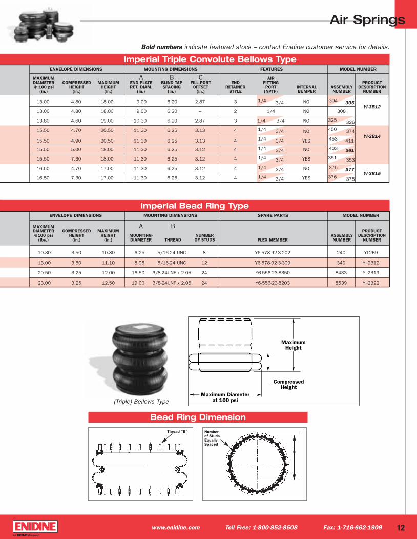
Imperial Triple Convolute Bellows Type
(Triple) Bellows Type
Imperial Bead Ring TypeENVELOPE DIMENSIONS MOUNTING DIMENSIONS SPARE PARTS MODEL NUMBER
10.30 3.50 10.80 6.25 5/16-24 UNC 8 Y6-578-92-3-202 240 YI-2B9
13.00 3.50 11.10 8.95 5/16-24 UNC 12 Y6-578-92-3-309 340 YI-2B12
20.50 3.25 12.00 16.50 3/8-24UNF x 2.05 24 Y6-556-23-8350 8433 YI-2B19
23.00 3.25 12.50 19.00 3/8-24UNF x 2.05 24 Y6-556-23-8203 8539 YI-2B22
Bead Ring Dimension
Thread “B” Numberof StudsEquallySpaced
ENVELOPE DIMENSIONS MOUNTING DIMENSIONS FEATURES MODEL NUMBER
MAXIMUM A B C AIRDIAMETER COMPRESSED MAXIMUM END PLATE BLIND TAP FILL PORT END FITTING PRODUCT@ 100 psi HEIGHT HEIGHT RET. DIAM. SPACING OFFSET RETAINER PORT INTERNAL ASSEMBLY DESCRIPTION
(in.) (in.) (in.) (in.) (in.) (in.) STYLE (NPTF) BUMPER NUMBER NUMBER
MAXIMUM A BDIAMETER COMPRESSED MAXIMUM PRODUCT@100 psi HEIGHT HEIGHT MOUNTING- NUMBER ASSEMBLY DESCRIPTION
(lbs.) (in.) (in.) DIAMETER THREAD OF STUDS FLEX MEMBER NUMBER NUMBER
A
12
13.00 4.80 18.00 9.00 6.20 2.87 3 1/4 3/4 NO 304 305YI-3B12
13.00 4.80 18.00 9.00 6.20 – 2 1/4 NO 308
13.80 4.60 19.00 10.30 6.20 2.87 3 1/4 3/4 NO 325 326
15.50 4.70 20.50 11.30 6.25 3.13 4 1/4 3/4 NO 450 374
15.50 4.90 20.50 11.30 6.25 3.13 4 1/4 3/4 YES 453 411YI-3B14
15.50 5.00 18.00 11.30 6.25 3.12 4 1/4 3/4 NO 403 361
15.50 7.30 18.00 11.30 6.25 3.12 4 1/4 3/4 YES 351 353
16.50 4.70 17.00 11.30 6.25 3.12 4 1/4 3/4 NO 375 377YI-3B15
16.50 7.30 17.00 11.30 6.25 3.12 4 1/4 3/4 YES 376 378
www.enidine.com Toll Free: 1-800-852-8508 Fax: 1-716-662-1909
Bold numbers indicate featured stock – contact Enidine customer service for details.
Airsprings1-04-IMP-BP 2/18/04 3:15 PM Page 14
YI-1S3-013 5/8-11 UNC x 1"�YI-1S4-007 3/4-16 UNF x 9/16"�YI-1S5-010 3/4-16 UNF x 9/16"�
STYLE 1
* * Listed strokes start from the compressed height of the Air Spring.** To obtain the lower load range limit (i.e., minimum load @ 20 psi), divide the smaller value by 5.
*** In the “Isolation Specification” section, this data reflects the approximate percentage of isolation obtainable, if the design height is at the center of the designheight range, and the load per air spring is within the isolator load range. Note: For values other than 100 psi, consult factory.
Air Springs
Imperial Rolling Lobe Type
YI-1R8005 13.00 3,280 2,950 — — 3,000 – 3,100 1.33 10.5 – 13.0 95 98 99
009 11.80 2,800 — — , — 2,700 – 2,900 1.17 10.5 – 13.0 96 98 99
YI-1R9003 12.30 3,350 3,040 1,300 1,250 3,200 – 3,700 1.42 8.0 – 12.0 93 98 99
009 8.60 4,150 1,600 — , 900 3,900 – 4,400 1.67 6.0 – 7.5 91 97 99
YI-1R10 089 14.10 5,100 5,250 3,550 2,100 5,000 – 5,200 1.25 9.5 – 13.5 96 99 99
YI-1R11028 9.30 6,450 3,800 — , 2,300 5,500 – 6,700 1.58 6.0 – 10.0 95 98 99
039 11.00 6,700 5,750 — , 2,300 6,500 – 7,000 1.67 8.0 – 12.0 94 98 99
092 13.40 7,440 7,200 4,350 2,700 6,800 – 7,600 1.42 10.5 – 16.5 96 99 99
095 9.10 7,100 3,800 — , 2,400 6,800 – 7,300 1.58 7.0 – 9.0 94 98 99
YI-1R12 103 17.50 7,450 7,050 6,600 2,600 6,900 – 7,300 1.25 15.0 – 20.0 96 99 99
132 10.80 7,350 5,900 — , 2,700 7,400 – 7,600 1.67 8.0 – 10.0 93 98 99
256 19.60 7,575 7,225 6,900 3,100 7,000 – 7,300 1.17 16.0 – 20.0 96 99 99
274 14.70 7,300 7,300 5,100 3,000 7,300 – 7,500 1.17 11.3 – 14.3 96 99 99
019 16.90 8,500 8,500 — — 8,400 – 8,500 1.17 14.0 – 18.0 96 99 99
YI-1R14 018 14.80 8,400 8,400 6,100 2,500 8,400 – 8,500 1.25 11.0 – 16.5 96 99 99
037 12.30 10,500 8,500 3,000 2,900 10,400 – 11,000 1.75 7.5 – 11.0 92 98 99
MODEL NUMBER ACTUATION SPECIFICATIONS ISOLATION SPECIFICATIONS
ISOLATOR APPROXIMATE DESIGNPRODUCT MAXIMUM LOAD RANGE SYSTEM NATURAL HEIGHT
DESCRIPTION ASSEMBLY STROKE 4.0 8.0 12.0 MAXIMUM @ 100 psi** FREQUENCY RANGE 7.25 14.5 30 NUMBER NUMBER (in.) (in.) (in.) (in.) STROKE (lbs.) Hz (in.) Hz Hz Hz
FORCE (lbs.) @ 100 psi AT A STROKE OF:* ***% ISOLATION AT INPUT FREQ OF:
YI-1S3011 4.40 400 400 —, 110 350 – 400 2.00 5.0 – 6.0 92 97 99
013 2.10 560 —, —, 120 440 – 580 3.25 2.0 – 3.0 71 93 98
YI-1S4007 4.90 850 830 —, 310 840 – 850 2.17 3.8 – 4.4 90 97 99
008 6.50 700 900 850 540 800 – 900 1.33 6.5 – 7.5 95 98 99
005 5.50 1,000 1,100 900 800 1,000 – 1,100 1.58 6.2 – 7.2 95 98 99
YI-1S5 006 6.50 1,000 1,150 1,100 750 1,050 – 1,100 1.50 7.0 – 9.0 96 99 99
010 4.00 1,100 1,000 1,000 560 1,000 – 1,100 2.00 3.8 – 4.3 90 97 99
YI-1S6 023 6.80 1,770 1,630 1,590 1,200 1,560 – 1,630 1.58 7.0 – 8.6 94 98 99
MODEL NUMBER ACTUATION SPECIFICATIONS ISOLATION SPECIFICATIONS
ISOLATOR APPROXIMATE DESIGNPRODUCT MAXIMUM LOAD RANGE SYSTEM NATURAL HEIGHT
DESCRIPTION ASSEMBLY STROKE 1.0 3.0 5.0 MAXIMUM @ 100 psi** FREQUENCY RANGE 7.25 14.5 30 NUMBER NUMBER (in.) (in.) (in.) (in.) STROKE (lbs.) Hz (in.) Hz Hz Hz
FORCE (lbs.) @ 100 psi AT A STROKE OF:* ***% ISOLATION AT INPUT FREQ OF:
Imperial Sleeve Type
13 www.enidine.com Toll Free: 1-800-852-8508 Fax: 1-716-662-1909
Important Note: All catalog performance data is based on 100 psi maximum operating pressure. For product selection at pressures less than 100 psi, please refer tothe manual selection procedure within this catalog or use E.A.S. our automated sizing software or contact Enidine customer service at 1-800-852-8508.
End Retainer StylesSTYLE 2
Bold numbers indicate featured stock – contact Enidine customer service for details.
Airsprings1-04-IMP-BP 2/18/04 3:15 PM Page 15

3.25 3.60 8.00 2.75 2.75 1 1/8 NO 011YI-1S3
3.60 1.50 3.60 2.40 3.40 2 1/8 NO 013
4.60 2.20 7.10 4.10 4.10 2 1/8 NO 007YI-1S4
4.60 4.00 10.50 4.10 4.10 1 1/8 NO 008
5.60 4.00 9.50 5.10 5.10 1 1/8 NO 005
5.60 4.00 10.50 5.10 5.10 1 1/8 NO 006 YI-1S5
5.60 2.20 6.25 5.10 5.10 2 1/8 NO 010
6.80 4.10 10.90 6.30 6.30 1 1/8 NO 023 YI-1S6M20-2.5-6gx 10 mm Long
3/8-16 UNCx 0.50 DP.
1/2-13 UNCx 0.63 DP.
1/2-13 UNCx 0.63 DP.
1/2-13 UNCx 0.63 DP.
3/8-16 UNCx 0.50 DP.
5/16-18 UNCx 0.44 DP.
1/2-13 UNCx 0.63 DP.
Air Springs
Imperial Rolling Lobe Type
8.70 5.60 18.60 NO 005YI-1R8
8.70 6.80 18.60 YES 009
9.50 5.60 17.90 NO 003YI-1R9
9.50 3.20 11.80 NO 009
11.00 6.00 20.10 NO 089 YI-1R10
11.50 3.70 13.00 NO 028YI-1R11
11.70 6.10 17.10 YES 039
12.70 7.70 21.10 YES 092
12.70 4.40 13.50 YES 095
12.70 9.50 27.00 YES 103YI-1R12
12.90 6.10 16.90 YES 132
12.60 9.50 29.10 YES 256
12.80 8.10 22.80 YES 274
14.60 8.90 25.80 YES 019
14.60 7.70 22.50 YES 018 YI-1R14
14.80 5.70 18.00 YES 037
FOR ROLLING LOBE TYPE AIR SPRINGS:
CONTACT YOUR LOCAL REPRESENTATIVE OR ENIDINE
FOR MOUNTING AND AIR FITTING DIMENSIONS.
ENVELOPE DIMENSIONS MOUNTING DIMENSIONS FEATURES MODEL NUMBER
MAXIMUM A B D AIRDIAMETER COMPRESSED MAXIMUM UPPER END LOWER END BLIND TAP END FITTING PRODUCT@ 100 psi HEIGHT HEIGHT PLATE DIAM. PLATE DIAM.FOR MOUNTING RETAINER PORT INTERNAL ASSEMBLY DESCRIPTION
(in.) (in.) (In.) (in.) (In.) (in.) STYLE (NPTF) BUMPER NUMBER NUMBER
Sleeve Type Rolling Lobe Type
ENVELOPE DIMENSIONS MOUNTING DIMENSIONS FEATURES MODEL NUMBER
MAXIMUM A B D AIRDIAMETER COMPRESSED MAXIMUM UPPER END LOWER END BLIND TAP END FITTING PRODUCT@ 100 psi HEIGHT HEIGHT PLATE DIAM. PLATE DIAM.FOR MOUNTING RETAINER PORT INTERNAL ASSEMBLY DESCRIPTION
(in.) (in.) (In.) (in.) (In.) (in.) STYLE (NPTF) BUMPER NUMBER NUMBER
Imperial Sleeve Type
14www.enidine.com Toll Free: 1-800-852-8508 Fax: 1-716-662-1909
Bold numbers indicate featured stock – contact Enidine customer service for details.
✝
Airsprings1-04-IMP-BP 2/18/04 3:15 PM Page 16
Air Springs
15 www.enidine.com Toll Free: 1-800-852-8508 Fax: 1-716-662-1909
Selecting an Enidine Air Spring for Actuation
** All Force values in the Selection Chart are based on a maximum operating pressure of 100 psi. Actual force capabilities of the Air Spring depend on the air pressureavailable. The Corrected Force calculation compensates for available air pressure.
Sizing InstructionsStep 1: Fill out the Application Worksheet.
Step 2: In most applications, a constant actuation force over thestroke is not required and sizing should begin with Single ConvoluteBellows Type Air Springs. However, if a constant actuation force overthe stroke is required, consider only the Sleeve and Rolling LobeType Air Springs.
Step 3: Refer to the Selection Chart under Actuation Specifications.In the Force (lbs.) At A Stroke Of: Data Table choose the columnthat is equal to or exceeds the Stroke Required (S) (i.e., if a stroke of 2.5 in. is required, refer to the 3.0 in. column). Identify the first AirSpring model that will generate a force equal to or greater than theCorrected Force (FC) required. This is the Enidine Air Spring that willbest serve your application. Select a model that includes an internalbumper if one is needed in the application. Availability of internalbumpers can be found under the Features table for each Air Spring.
Step 4: Verify the Envelope Dimensions of the selected Enidine AirSpring to ensure that the Air Spring will fit the application. Allow a 2 in. clearance on the diameter to prevent abrasion of the flex member. Select the Model Number that provides the Featuresand Mounting Dimensions required for the application.
Installation Considerations• External extension stops are required to limit the extension of the
Air Spring(s).
• The path of motion must be guided, as Air Springs provide little lateral stability.
Sizing ExampleA 3,200-lb. conveyor carrying an 1,200-lb. package needs to be lifted1.8 in. to transfer the package to another conveyor. There will be fourActuators utilized and the warehouse has air lines with 50 psi. A constant actuation force is not required. Ambient temperature is68°F. There is a 12-in. square space to house each Air Spring.Compression and extension stops are provided. Any Air Fitting Portand End Retainer Style would be acceptable.
Step 1: From the completed Application Worksheet, we know:
• Corrected force per actuator is 2,200 lbs.
• Stroke required is 1.8 inches
• An internal bumper is not required
• A constant actuation force is not required
• Working temperature is 68°F
Step 2: A constant force is not needed. Therefore, all Air Springtypes are considered, beginning with Single Convolute Bellows.
Step 3: In the 2.0 in. column under the Force lbs. At A Stroke Of:Data Table, identify an Air Spring that can generate 2,200 lbs. offorce. No internal bumper is required. Model YI-1B8-550 is selected.
Step 4: The maximum diameter of a YI-1B8-550 is 8.7 in. Therefore, we need a 10.7-in. diameter space to house the AirSpring. A 12-in. square space will easily house the Air Spring. AnyAir Fitting Port and End Retainer Style would be acceptable. Model YI-1B8-550 is selected.
Application Worksheet: Actuation
The following data should be given: Symbol Unit
1. Total force required for actuation Ft ________ lbs.
2. Number of actuators n ________
3. Stroke required s ________ in.
4. Available air pressure at the point of installation p ________ psi
5. Working temperature range t ________ °F
6. An internal bumper will be required if any of the following conditions occur:
• External compression stops are not provided
• Severe impacting at the compressed height of the Air Spring.
Internal BumperNo Bumper
7. Is a constant actuation force required for this application?Yes - only Sleeve and Rolling Lobe Type Air SpringsNo - all type Air Springs
Yes
Calculation:
Force per Air Spring Example:
FtF = ––– lbs.
n
n = 4
4,400 lbs. F = ––––––––
4
F = lbs. F = 1,100 lbs.
Corrected Force [Fc]:* Example:
F x 100 psi p = 50 psiFc = ––––––––––
p
1,100 x 100Fc = ______ lbs. Fc = ––––––––––––
50
Fc = 2,200 lbs.
Ft = 4,400 lbs.
Airsprings1-04-IMP-BP 2/18/04 3:15 PM Page 17
Air Springs
16www.enidine.com Toll Free: 1-800-852-8508 Fax: 1-716-662-1909
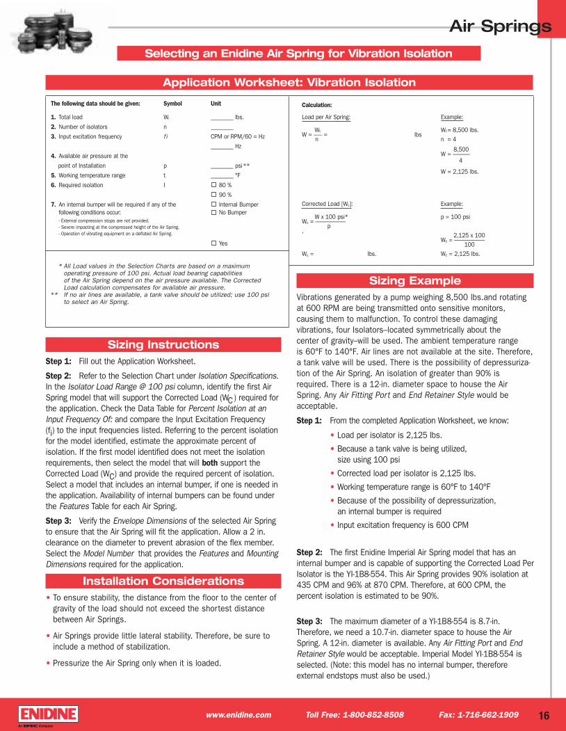
Sizing InstructionsStep 1: Fill out the Application Worksheet.
Step 2: Refer to the Selection Chart under Isolation Specifications.In the Isolator Load Range @ 100 psi column, identify the first AirSpring model that will support the Corrected Load (WC) required forthe application. Check the Data Table for Percent Isolation at anInput Frequency Of: and compare the Input Excitation Frequency (fi) to the input frequencies listed. Referring to the percent isolationfor the model identified, estimate the approximate percent of isolation. If the first model identified does not meet the isolationrequirements, then select the model that will both support theCorrected Load (WC) and provide the required percent of isolation.Select a model that includes an internal bumper, if one is needed inthe application. Availability of internal bumpers can be found underthe Features Table for each Air Spring.
Step 3: Verify the Envelope Dimensions of the selected Air Springto ensure that the Air Spring will fit the application. Allow a 2 in.clearance on the diameter to prevent abrasion of the flex member.Select the Model Number that provides the Features and MountingDimensions required for the application.
Installation Considerations• To ensure stability, the distance from the floor to the center of
gravity of the load should not exceed the shortest distancebetween Air Springs.
• Air Springs provide little lateral stability. Therefore, be sure toinclude a method of stabilization.
• Pressurize the Air Spring only when it is loaded.
Application Worksheet: Vibration Isolation
Corrected Load [Wc]: Example:
W x 100 psi* p = 100 psiWc = ––---------------------
p,
2,125 x 100Wc = ––---------------------
100Wc = lbs. Wc = 2,125 lbs.
The following data should be given: Symbol Unit
1. Total load Wt ________ lbs.
2. Number of isolators n ________
3. Input excitation frequency f i CPM or RPM/60 = Hz
________ Hz
4. Available air pressure at the
point of Installation p ________ psi**
5. Working temperature range t ________ °F
6. Required isolation I 80 %
90 %
7. An internal bumper will be required if any of the Internal Bumperfollowing conditions occur: No Bumper- External compression stops are not provided.- Severe impacting at the compressed height of the Air Spring.- Operation of vibrating equipment on a deflated Air Spring.
Yes
* All Load values in the Selection Charts are based on a maximum operating pressure of 100 psi. Actual load bearing capabilities of the Air Spring depend on the air pressure available. The Corrected Load calculation compensates for available air pressure.
** If no air lines are available, a tank valve should be utilized; use 100 psi to select an Air Spring.
Sizing ExampleVibrations generated by a pump weighing 8,500 lbs.and rotatingat 600 RPM are being transmitted onto sensitive monitors, causing them to malfunction. To control these damaging vibrations, four Isolators–located symmetrically about the center of gravity–will be used. The ambient temperature range is 60°F to 140°F. Air lines are not available at the site. Therefore,a tank valve will be used. There is the possibility of depressuriza-tion of the Air Spring. An isolation of greater than 90% isrequired. There is a 12-in. diameter space to house the AirSpring. Any Air Fitting Port and End Retainer Style would beacceptable.
Step 1: From the completed Application Worksheet, we know:
• Load per isolator is 2,125 lbs.
• Because a tank valve is being utilized, size using 100 psi
• Corrected load per isolator is 2,125 lbs.
• Working temperature range is 60°F to 140°F
• Because of the possibility of depressurization, an internal bumper is required
• Input excitation frequency is 600 CPM
Step 2: The first Enidine Imperial Air Spring model that has aninternal bumper and is capable of supporting the Corrected Load PerIsolator is the YI-1B8-554. This Air Spring provides 90% isolation at435 CPM and 96% at 870 CPM. Therefore, at 600 CPM, the percent isolation is estimated to be 90%.
Step 3: The maximum diameter of a YI-1B8-554 is 8.7-in.Therefore, we need a 10.7-in. diameter space to house the AirSpring. A 12-in. diameter is available. Any Air Fitting Port and EndRetainer Style would be acceptable. Imperial Model YI-1B8-554 isselected. (Note: this model has no internal bumper, therefore external endstops must also be used.)
Calculation:
Load per Air Spring: Example:
Wt Wt = 8,500 lbs.W = ––– = lbs
n n = 4
8,500 W = ––––––
4
W = 2,125 lbs.
Selecting an Enidine Air Spring for Vibration Isolation
Airsprings1-04-IMP-BP 2/18/04 3:15 PM Page 18
Air Springs
17 www.enidine.com Toll Free: 1-800-852-8508 Fax: 1-716-662-1909
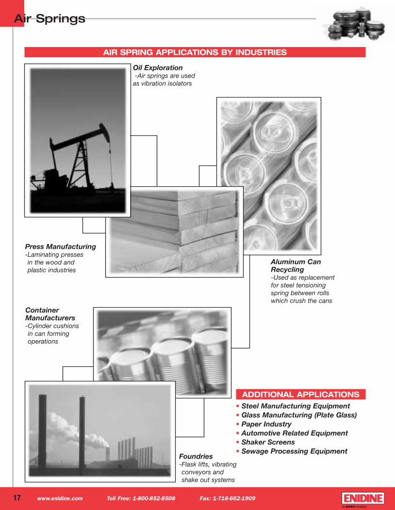
• Steel Manufacturing Equipment• Glass Manufacturing (Plate Glass)• Paper Industry• Automotive Related Equipment• Shaker Screens• Sewage Processing Equipment
AIR SPRING APPLICATIONS BY INDUSTRIES
Foundries-Flask lifts, vibrating conveyors and shake out systems
Press Manufacturing-Laminating presses in the wood and plastic industries
Oil Exploration-Air springs are used
as vibration isolators
Container Manufacturers-Cylinder cushions in can forming operations
Aluminum CanRecycling-Used as replacement for steel tensioning spring between rolls which crush the cans
ADDITIONAL APPLICATIONS
Airsprings1-04-IMP-BP 2/18/04 3:15 PM Page 19
Air Springs
18www.enidine.com Toll Free: 1-800-852-8508 Fax: 1-716-662-1909
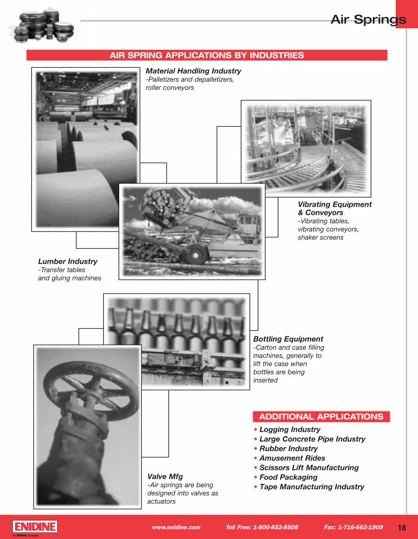
AIR SPRING APPLICATIONS BY INDUSTRIES
• Logging Industry• Large Concrete Pipe Industry• Rubber Industry• Amusement Rides• Scissors Lift Manufacturing• Food Packaging• Tape Manufacturing Industry
Lumber Industry-Transfer tables and gluing machines
Material Handling Industry-Palletizers and depalletizers, roller conveyors
Bottling Equipment-Carton and case fillingmachines, generally to lift the case when bottles are beinginserted
Vibrating Equipment& Conveyors-Vibrating tables, vibrating conveyors,shaker screens
Valve Mfg-Air springs are beingdesigned into valves asactuators
ADDITIONAL APPLICATIONS
Airsprings1-04-IMP-BP 2/18/04 3:15 PM Page 20

IND092 2/04 7.5MSolutions in Energy Absorption and Vibration Isolation.
Enidine Incorporated7 Centre DriveOrchard Park, New York 14127 • USAPhone: 716-662-1900Fax: 716-662-1909www.enidine.com
Subsidiaries and Affiliates:
Enidine West184 Technology Dr., Suite 201Irvine, California 92618 • USAPhone: 949-727-9112Fax: 949-727-9107www.enidine.com
Enidine GmbHRheinauenstr, 579415 Bad BellingenRheinweiler • GermanyPhone: 49 7635 8101 0Fax: 49 7635 8101 99www.enidine.de
Enidine Co. Ltd.398, Cigasaki-Cho, Tsuzuki-KuYokohama-Shi, Kanagawa 224-0031JapanPhone: 81 45 947 1671Fax: 81 45 945 3967www.enidine.co.jp
Enidine Corporativo De Mexico, S.A. de C.V.Av. Patria 3124-ACol El SauzGuadalajara, CP Jalisco • Mexico 45080Phone: 52 3 646-8100Fax: 52 3 646-6755www.enidine.com.mx
Enidine U.K. Ltd.Patrick Gregory RoadWolverhampton West Midlands, WV11 3DZUnited KingdomPhone: 44 1902 304000Fax: 44 1902 305676www.enidine.co.uk
ENIDINE PRODUCTSShock Absorbers • Rate Controls • Air Springs
Elastomeric Isolators • Wire Rope Isolators • Compact Wire Rope Isolators
Airsprings1-04-IMP-BP 2/18/04 3:14 PM Page 1