installation instructions · inflating the air springs when inflating air springs, add air...
TRANSCRIPT
INSTALLATION INSTRUCTIONS
riderite.com
2808
12-15
SECTION 1 - AIR SPRING SECTION 2 - AIR ACCESSORY
riderite.com1
! IMPORTANTPLEASE DON’T HURT YOURSELF, YOUR KIT OR YOUR VEHICLE. TAKE A MINUTE TO READ THIS IMPORTANT INFORMATION.
This kit is to be used on a pickup truck only, and DOES NOT INCREASE YOUR VEHICLE’S MAXIMUM LOAD.
SAFE INSTALLATIONPlease take all safety precautions during installation. A hydraulic jack can fail, and if that happens, you can be seriously hurt, or worse, if you are relying on it to hold up the vehicle. If you use a hydraulic jack, secure jack stands in the appropriate locations and chock any tires still touching the ground.
Wear safety glasses or goggles. Your eyes may be lower than some parts and pieces, and you don’t want to lose an eye.
Remove the possibility of any electrical issues by disconnecting the negative battery cable.
KIT CLEARANCEThere must be a minimum of 1/2” clearance around all installed components when the Air Springs are inflated and under a load. The Air Springs must flex and expand during operation, so the clearance keeps the kit from rubbing against parts of the vehicle.
VEHICLE GVWRNEVER exceed the maximum load recommended by the vehicle manufacturer (GVWR). The GVWR can be found in your vehicle’s owner’s manual or on the data plate on the driver’s side door. Consult your local dealership for additional GVWR specifications.
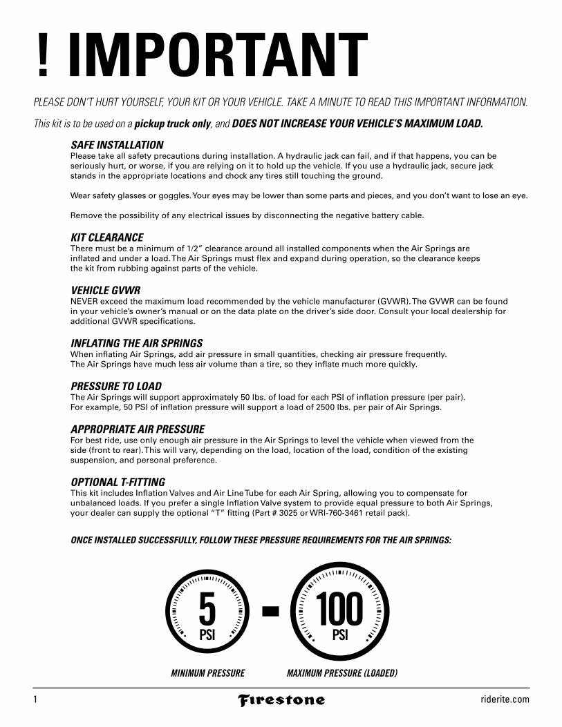
INFLATING THE AIR SPRINGSWhen inflating Air Springs, add air pressure in small quantities, checking air pressure frequently. The Air Springs have much less air volume than a tire, so they inflate much more quickly.
PRESSURE TO LOADThe Air Springs will support approximately 50 lbs. of load for each PSI of inflation pressure (per pair). For example, 50 PSI of inflation pressure will support a load of 2500 lbs. per pair of Air Springs.
APPROPRIATE AIR PRESSUREFor best ride, use only enough air pressure in the Air Springs to level the vehicle when viewed from the side (front to rear). This will vary, depending on the load, location of the load, condition of the existing suspension, and personal preference.
OPTIONAL T-FITTINGThis kit includes Inflation Valves and Air Line Tube for each Air Spring, allowing you to compensate for unbalanced loads. If you prefer a single Inflation Valve system to provide equal pressure to both Air Springs, your dealer can supply the optional “T” fitting (Part # 3025 or WRI-760-3461 retail pack).
ONCE INSTALLED SUCCESSFULLY, FOLLOW THESE PRESSURE REQUIREMENTS FOR THE AIR SPRINGS:
2808 Installation Instructions 2
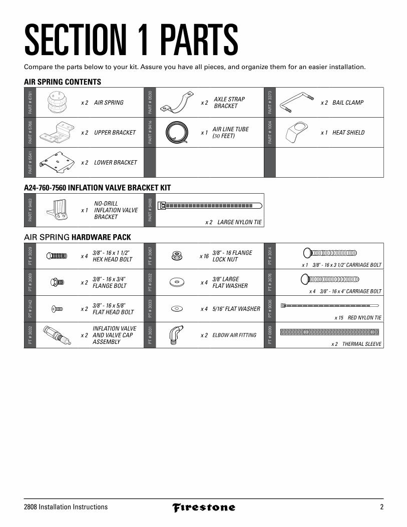
SECTION 1 PARTSCompare the parts below to your kit. Assure you have all pieces, and organize them for an easier installation.
AIR SPRING CONTENTS
PAR
T #
6781
x 2 AIR SPRING
PAR
T #
0530
x 2 AXLE STRAPBRACKET
PAR
T #
3373
x 2 BAIL CLAMP
PAR
T #
5766
x 2 UPPER BRACKET
PA
RT
# 94
16
x 1 AIR LINE TUBE(30 FEET)
PAR
T #
1004
x 1 HEAT SHIELD
PAR
T #
5541
x 2 LOWER BRACKET
A24-760-7560 INFLATION VALVE BRACKET KIT
PAR
T #
9483
x 1NO-DRILL INFLATION VALVE BRACKET
PAR
T #
9488
x 2 LARGE NYLON TIE
AIR SPRING HARDWARE PACK
PT
# 30
29
x 4 3/8" - 16 x 1 1/2"HEX HEAD BOLT
PT
# 30
67
x 16 3/8" - 16 FLANGELOCK NUT
PT
# 30
14x 1 3/8" - 16 x 3 1/2" CARRIAGE BOLT
PT
# 30
69
x 2 3/8" - 16 x 3/4"FLANGE BOLT
PT
# 05
32
x 4 3/8" LARGEFLAT WASHER
PT
# 30
76
x 4 3/8" - 16 x 4" CARRIAGE BOLT
PT
# 31
42
x 2 3/8" - 16 x 5/8"FLAT HEAD BOLT
PT
# 30
33
x 4 5/16" FLAT WASHER
PT
# 90
36
x 15 RED NYLON TIE
PT
# 30
32
x 2INFLATION VALVEAND VALVE CAPASSEMBLY P
T #
3031
x 2 ELBOW AIR FITTING
PT
# 08
99
x 2 THERMAL SLEEVE
riderite.com3
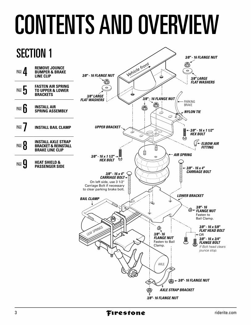
CONTENTS AND OVERVIEWSECTION 1PAGE 4 REMOVE JOUNCE
BUMPER & BRAKE LINE CLIP
PAGE 5 FASTEN AIR SPRING TO UPPER & LOWER BRACKETS
PAGE 6 INSTALL AIR SPRING ASSEMBLY
PAGE 7 INSTALL BAIL CLAMP
PAGE 8 INSTALL AXLE STRAP BRACKET & REINSTALL BRAKE LINE CLIP
PAGE 9 HEAT SHIELD &PASSENGER SIDE
Vehicle front
3/8" - 16 FLANGE NUT
3/8" - 16 FLANGE NUT
3/8" LARGE FLAT WASHERS
3/8" LARGE FLAT WASHERS
3/8" - 16 x 1 1/2" HEX BOLT
NYLON TIE
3/8" - 16 x 4" CARRIAGE BOLT
LOWER BRACKETBAIL CLAMP
3/8" - 16 x 4" CARRIAGE BOLT
3/8" - 16 x 5/8" FLAT HEAD BOLT
3/8" - 16 x 3/4" FLANGE BOLT
3/8" - 16 x 1 1/2"HEX BOLT
ELBOW AIRFITTING
AIR SPRING
UPPER BRACKET
3/8"- 16 FLANGE NUT
3/8"- 16 FLANGE NUTFasten to Bail Clamp.
3/8"- 16 FLANGE NUTFasten to Bail Clamp.
3/8"- 16 FLANGE NUT
AXLE STRAP BRACKET
OR
AXLE
LEAF SPRINGS
If Bolt head clears jounce stop.
On left side, use 3 1/2"Carriage Bolt if necessary
to clear parking brake bolt.
PARKINGBRAKE
3/8" - 16 FLANGE NUT
2808 Installation Instructions 4
VEHICLEFRAME
JOUNCEBUMPER
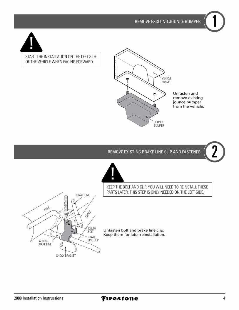
Unfasten and remove existing jounce bumper from the vehicle.
BRAKE LINE
13 MMBOLT
BRAKE LINE CLIP
SHOCK BRACKET
PARKING BRAKE LINE
SHOC
KAXLE
Unfasten bolt and brake line clip.Keep them for later reinstallation.
REMOVE EXISTING JOUNCE BUMPER
REMOVE EXISTING BRAKE LINE CLIP AND FASTENER
1
2
KEEP THE BOLT AND CLIP. YOU WILL NEED TO REINSTALL THESE PARTS LATER. THIS STEP IS ONLY NEEDED ON THE LEFT SIDE.
START THE INSTALLATION ON THE LEFT SIDE OF THE VEHICLE WHEN FACING FORWARD.
riderite.com5
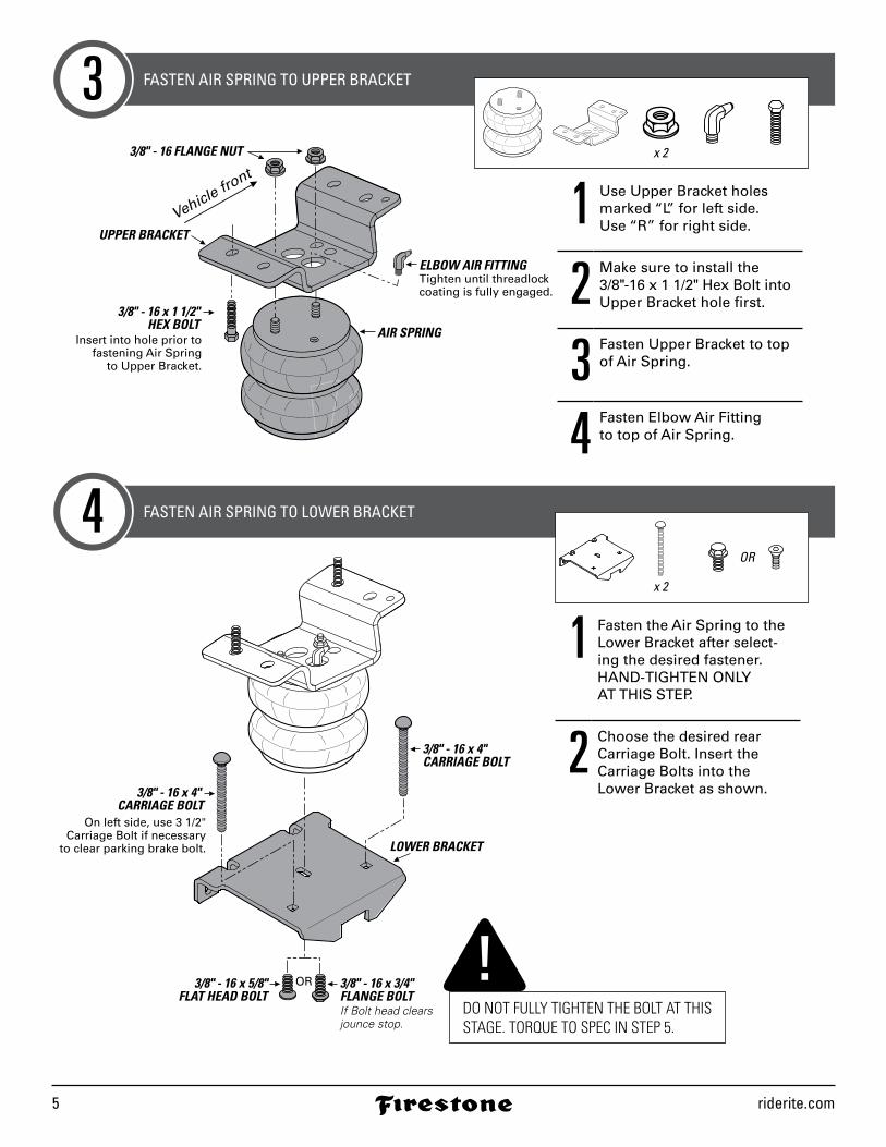
3/8" - 16 x 1 1/2"HEX BOLT
ELBOW AIR FITTINGTighten until threadlock coating is fully engaged.
AIR SPRING
UPPER BRACKET
Insert into hole prior tofastening Air Spring
to Upper Bracket.
Vehicle front
3/8" - 16 FLANGE NUT
LOWER BRACKET
3/8" - 16 x 4" CARRIAGE BOLT
3/8" - 16 x 5/8"FLAT HEAD BOLT
3/8" - 16 x 3/4" FLANGE BOLT
OR
If Bolt head clears jounce stop.
3/8" - 16 x 4" CARRIAGE BOLT
On left side, use 3 1/2"Carriage Bolt if necessary
to clear parking brake bolt.
FASTEN AIR SPRING TO UPPER BRACKET
FASTEN AIR SPRING TO LOWER BRACKET
3
4
x 2
x 2
OR
1 Use Upper Bracket holes marked “L” for left side. Use “R” for right side.
2 Make sure to install the 3/8" -16 x 1 1/2" Hex Bolt into Upper Bracket hole first.
3 Fasten Upper Bracket to top of Air Spring.
4 Fasten Elbow Air Fitting to top of Air Spring.
1 Fasten the Air Spring to the Lower Bracket after select-ing the desired fastener. HAND-TIGHTEN ONLY AT THIS STEP.
2 Choose the desired rear Carriage Bolt. Insert the Carriage Bolts into the Lower Bracket as shown.
DO NOT FULLY TIGHTEN THE BOLT AT THIS STAGE. TORQUE TO SPEC IN STEP 5.
2808 Installation Instructions 6
AXLE
LEAF SPRINGS
Vehicle front
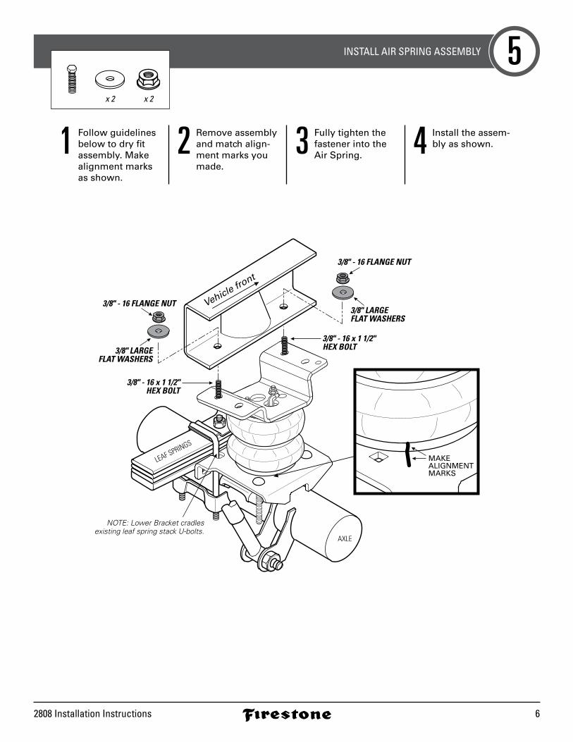
3/8" - 16 FLANGE NUT
3/8" - 16 FLANGE NUT
3/8" LARGEFLAT WASHERS
3/8" LARGE FLAT WASHERS
NOTE: Lower Bracket cradlesexisting leaf spring stack U-bolts.
MAKE ALIGNMENTMARKS
3/8" - 16 x 1 1/2"HEX BOLT
3/8" - 16 x 1 1/2"HEX BOLT
INSTALL AIR SPRING ASSEMBLY 5x 2x 2
1 Follow guidelinesbelow to dry fitassembly. Makealignment marksas shown.
2 Remove assembly and match align-ment marks you made.
3 Fully tighten the fastener into the Air Spring. 4 Install the assem-
bly as shown.
riderite.com7
AXLE
LEAF SPRINGS
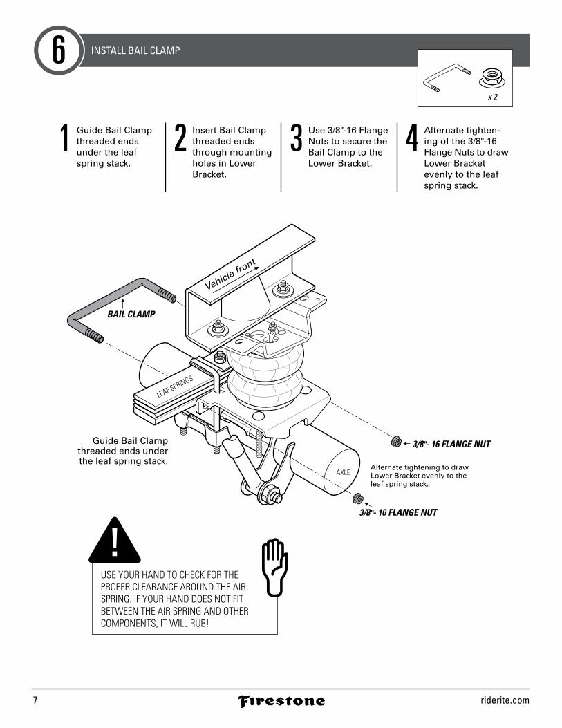
Guide Bail Clampthreaded ends underthe leaf spring stack.
Alternate tightening to draw Lower Bracket evenly to the leaf spring stack.
BAIL CLAMP
3/8"- 16 FLANGE NUT
3/8"- 16 FLANGE NUT
Vehicle front
INSTALL BAIL CLAMP6x 2
USE YOUR HAND TO CHECK FOR THE PROPER CLEARANCE AROUND THE AIR SPRING. IF YOUR HAND DOES NOT FIT BETWEEN THE AIR SPRING AND OTHER COMPONENTS, IT WILL RUB!
1 Guide Bail Clamp threaded ends under the leaf spring stack.
2 Insert Bail Clamp threaded ends through mounting holes in Lower Bracket.
3 Use 3/8" -16 Flange Nuts to secure the Bail Clamp to the Lower Bracket.
4 Alternate tighten-ing of the 3/8" -16 Flange Nuts to draw Lower Bracket evenly to the leaf spring stack.
2808 Installation Instructions 8
AXLE
LEAF SPRINGS
3/8" - 16 x 4" CARRIAGE BOLT
3/8" - 16 x 4" CARRIAGE BOLT
On left side, use 3 1/2"Carriage Bolt if necessary
to clear parking brake bolt.3/8"- 16 FLANGE NUT
3/8"- 16 FLANGE NUTAXLE STRAP BRACKET
NYLON TIE
PARKINGBRAKE
Vehicle front
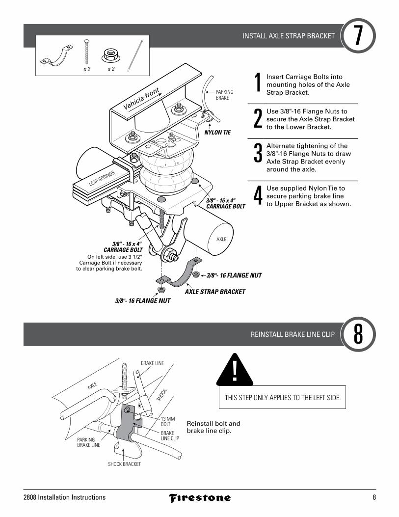
INSTALL AXLE STRAP BRACKET
REINSTALL BRAKE LINE CLIP
7
8
THIS STEP ONLY APPLIES TO THE LEFT SIDE.
x 2 x 2
BRAKE LINE
13 MMBOLT
BRAKE LINE CLIP
SHOCK BRACKET
PARKING BRAKE LINE
SHOC
KAXLE
Reinstall bolt and brake line clip.
1 Insert Carriage Bolts into mounting holes of the Axle Strap Bracket.
2 Use 3/8" -16 Flange Nuts to secure the Axle Strap Bracket to the Lower Bracket.
3 Alternate tightening of the 3/8" -16 Flange Nuts to draw Axle Strap Bracket evenly around the axle.
4 Use supplied Nylon Tie to secure parking brake line to Upper Bracket as shown.

riderite.com9
HEAT SHIELD
AIR SPRING
Position Heat Shield toclosest point of exhaust.
DO NOT PLACEDIRECTLY ABOVE AXLE.
HEAT SHIELD
INSTALL RIGHT SIDE WITH HEAT SHIELD9
RIGHT SIDE INSTALLATION MUST INCLUDE HEAT SHIELD!
AWESOME! You’re done with the left side. The right side installation is the same, with the addition of this step. Go complete Steps 1-2 for the right side, then complete this step before continuing to Step 3.
2808 Installation Instructions 10
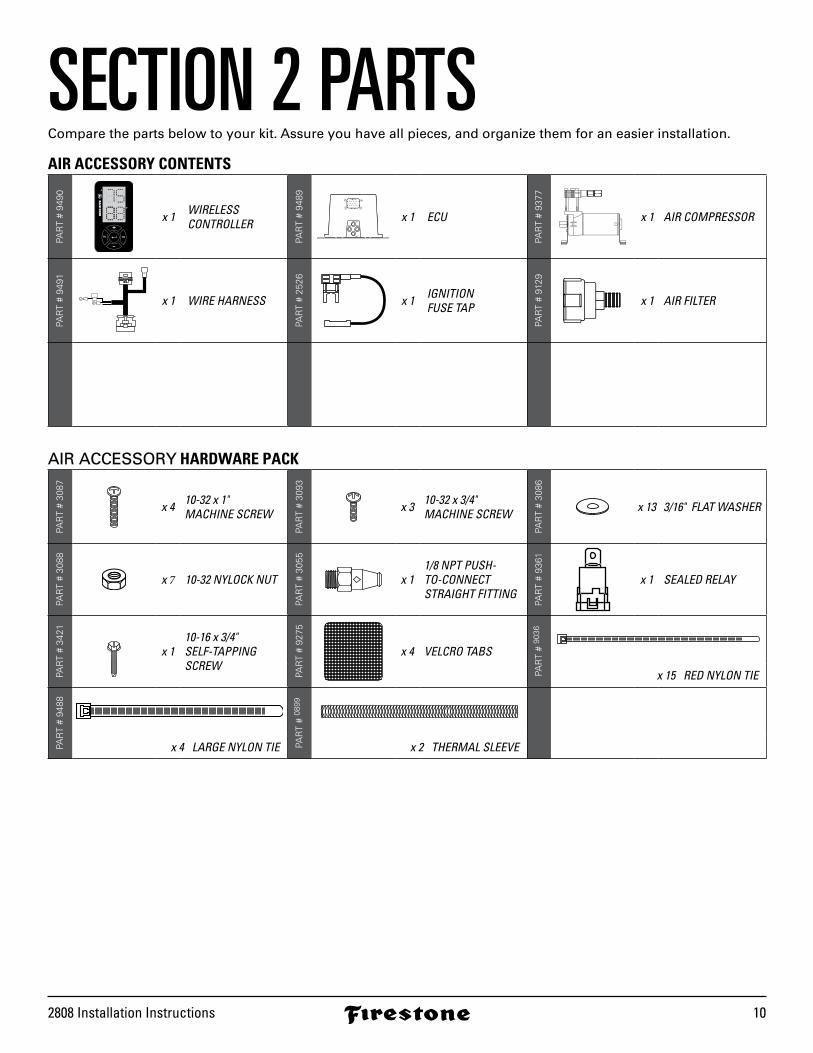
SECTION 2 PARTSCompare the parts below to your kit. Assure you have all pieces, and organize them for an easier installation.
AIR ACCESSORY CONTENTS
PAR
T #
9490
x 1 WIRELESSCONTROLLER
PAR
T #
9489
SUP
AS-1 AS-2
EXH
SUP
AS-1 AS-2
EXHx 1 ECU
PAR
T #
9377
x 1 AIR COMPRESSOR
PAR
T #
9491
x 1 WIRE HARNESSPA
RT
# 25
26x 1 IGNITION
FUSE TAP
PAR
T #
9129
x 1 AIR FILTER
AIR ACCESSORY HARDWARE PACK
PAR
T #
3087
x 4 10-32 x 1"MACHINE SCREW
PAR
T #
3093
x 3 10-32 x 3/4"MACHINE SCREW
PAR
T #
3086
x 13 3/16" FLAT WASHER
PAR
T #
3088
x 7 10-32 NYLOCK NUT
PAR
T #
3055
x 11/8 NPT PUSH- TO-CONNECT STRAIGHT FITTING
PAR
T #
9361
x 1 SEALED RELAY
PAR
T #
3421
x 110-16 x 3/4" SELF-TAPPING SCREW
PAR
T #
9275
x 4 VELCRO TABS
PAR
T #
9036
x 15 RED NYLON TIE
PAR
T #
9488
PAR
T #
0899
x 4 LARGE NYLON TIE x 2 THERMAL SLEEVE
riderite.com11
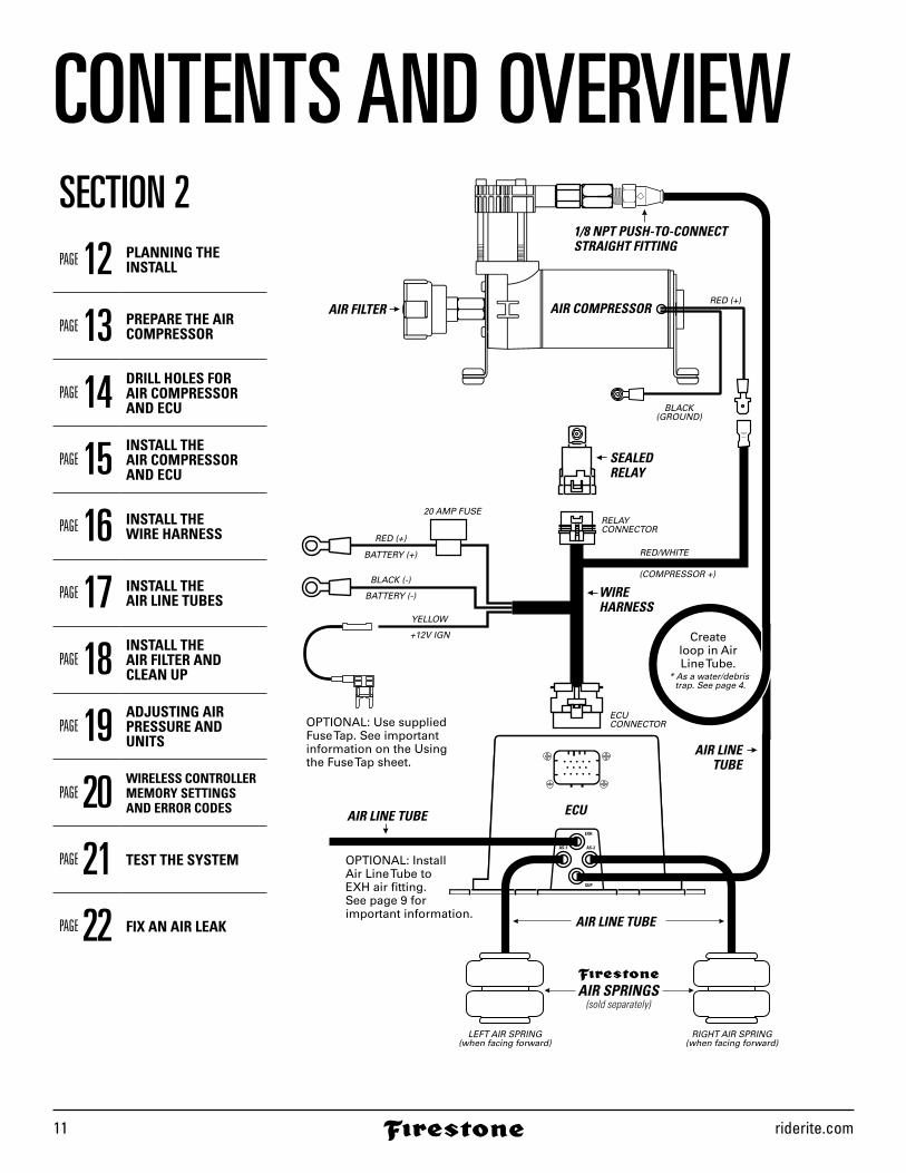
CONTENTS AND OVERVIEWSECTION 2PAGE 12 PLANNING THE
INSTALL
PAGE 13 PREPARE THE AIR COMPRESSOR
PAGE 14 DRILL HOLES FOR AIR COMPRESSOR AND ECU
PAGE 15 INSTALL THE AIR COMPRESSOR AND ECU
PAGE 16 INSTALL THE WIRE HARNESS
PAGE 17 INSTALL THE AIR LINE TUBES
PAGE 18 INSTALL THE AIR FILTER ANDCLEAN UP
PAGE 19 ADJUSTING AIR PRESSURE AND UNITS
PAGE 20 WIRELESS CONTROLLER MEMORY SETTINGS AND ERROR CODES
PAGE 21 TEST THE SYSTEM
PAGE 22 FIX AN AIR LEAK
SUP
AS-1 AS-2
EXH
SUP
AS-1 AS-2
EXH
ECU
AIR SPRINGS(sold separately)
1/8 NPT PUSH-TO-CONNECTSTRAIGHT FITTING
AIR LINE TUBE
AIR LINE TUBE
AIR LINETUBE
BLACK(GROUND)
RED (+)
20 AMP FUSE
RED (+)
RED/WHITE
ECU CONNECTOR
RELAYCONNECTOR
(COMPRESSOR +)
BATTERY (+)
YELLOW
+12V IGN
OPTIONAL: Use supplied Fuse Tap. See important information on the Usingthe Fuse Tap sheet.
OPTIONAL: InstallAir Line Tube toEXH air fitting.See page 9 forimportant information.
LEFT AIR SPRING(when facing forward)
RIGHT AIR SPRING(when facing forward)
WIREHARNESS
SEALEDRELAY
AIR FILTER AIR COMPRESSOR
* As a water/debris trap. See page 4.
Createloop in AirLine Tube.
BLACK (-)
BATTERY (-)
2808 Installation Instructions 12
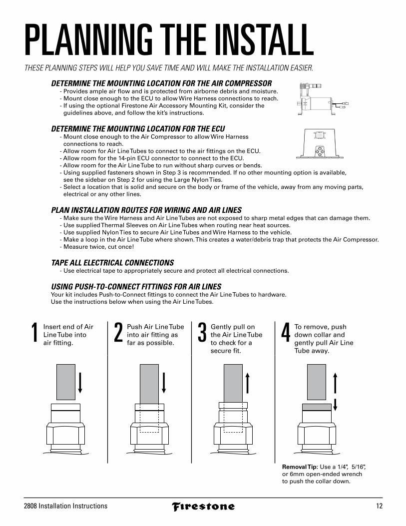
PLANNING THE INSTALLTHESE PLANNING STEPS WILL HELP YOU SAVE TIME AND WILL MAKE THE INSTALLATION EASIER.
DETERMINE THE MOUNTING LOCATION FOR THE AIR COMPRESSOR - Provides ample air flow and is protected from airborne debris and moisture. - Mount close enough to the ECU to allow Wire Harness connections to reach. - If using the optional Firestone Air Accessory Mounting Kit, consider the
guidelines above, and follow the kit’s instructions.
DETERMINE THE MOUNTING LOCATION FOR THE ECU - Mount close enough to the Air Compressor to allow Wire Harness
connections to reach. - Allow room for Air Line Tubes to connect to the air fittings on the ECU. - Allow room for the 14-pin ECU connector to connect to the ECU. - Allow room for the Air Line Tube to run without sharp curves or bends. - Using supplied fasteners shown in Step 3 is recommended. If no other mounting option is available,
see the sidebar on Step 2 for using the Large Nylon Ties. - Select a location that is solid and secure on the body or frame of the vehicle, away from any moving parts,
electrical or any other lines.
PLAN INSTALLATION ROUTES FOR WIRING AND AIR LINES - Make sure the Wire Harness and Air Line Tubes are not exposed to sharp metal edges that can damage them. - Use supplied Thermal Sleeves on Air Line Tubes when routing near heat sources. - Use supplied Nylon Ties to secure Air Line Tubes and Wire Harness to the vehicle. - Make a loop in the Air Line Tube where shown. This creates a water/debris trap that protects the Air Compressor. - Measure twice, cut once!
TAPE ALL ELECTRICAL CONNECTIONS - Use electrical tape to appropriately secure and protect all electrical connections.
USING PUSH-TO-CONNECT FITTINGS FOR AIR LINESYour kit includes Push-to-Connect fittings to connect the Air Line Tubes to hardware. Use the instructions below when using the Air Line Tubes.
1 Insert end of Air Line Tube into air fitting. 2 Push Air Line Tube
into air fitting asfar as possible. 3 Gently pull on
the Air Line Tube to check for a secure fit.
4 To remove, pushdown collar andgently pull Air LineTube away.
SUP
AS-1 AS-2
EXH
SUP
AS-1 AS-2
EXH
Removal Tip: Use a 1/4 ,̋ 5/16 ,̋ or 6mm open-ended wrench to push the collar down.
riderite.com13
AIR COMPRESSOR
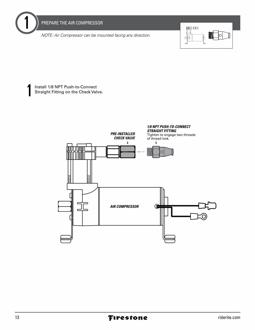
1/8 NPT PUSH-TO-CONNECT STRAIGHT FITTINGTighten to engage two threadsof thread lock.
PRE-INSTALLEDCHECK VALVE
PREPARE THE AIR COMPRESSOR1NOTE: Air Compressor can be mounted facing any direction.
1 Install 1/8 NPT Push-to-Connect Straight Fitting on the Check Valve.
2808 Installation Instructions 14
AIR COMPRESSOR
BLACKGROUND
WIRE
Use as template to mark drill locations.
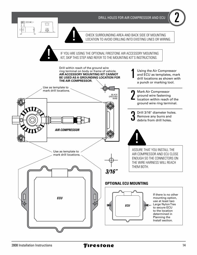
Drill within reach of the ground wire ring terminal on body or frame of vehicle.AIR ACCESSORY MOUNTING KIT CANNOT BE USED AS A GROUNDING LOCATION FOR THE AIR COMPRESSOR.
Use as template to mark drill locations.
ECUIf there is no othermounting option,use at least twoLarge Nylon Ties to secure ECU to the locationdetermined inPlanning theInstall section.
ECU
DRILL HOLES FOR AIR COMPRESSOR AND ECU 2
3/16”
IF YOU ARE USING THE OPTIONAL FIRESTONE AIR ACCESSORY MOUNTING KIT, SKIP THIS STEP AND REFER TO THE MOUNTING KIT’S INSTRUCTIONS.
CHECK SURROUNDING AREA AND BACK SIDE OF MOUNTING LOCATION TO AVOID DRILLING INTO EXISTING LINES OR WIRING.
1 Using the Air Compressor and ECU as templates, mark drill locations as shown with a punch or marking tool.
2 Mark Air Compressor ground wire fasteninglocation within reach of the ground wire ring terminal.
3 Drill 3/16" diameter holes. Remove any burrs and debris from drill holes.
ASSURE THAT YOU INSTALL THE AIR COMPRESSOR AND ECU CLOSE ENOUGH SO THE CONNECTORS ON THE WIRE HARNESS WILL REACH THEM BOTH.
SUP
AS-1 AS-2
EXH
SUP
AS-1 AS-2
EXH
OPTIONAL ECU MOUNTING

riderite.com15
AIR COMPRESSOR
Air Accessory mountingKit cannot be used as a grounding location for the Air compressor.
(or optional FirestoneAir AccessoryMounting Kit).
10-32 x 1” MACHINE SCREW
10-32 NYLOCK NUT
3/16” FLAT WASHER
3/16” FLAT WASHER
10-32NYLOCK NUT
3/16” FLATWASHER
10-16 x 3/4” SELF-TAPPING SCREW
BLACKGROUND WIRE
BODY OR FRAMEOF VEHICLE
BODY OR FRAMEOF VEHICLE
10-32 x 3/4” MACHINE SCREW
10-32 NYLOCK NUT
3/16” FLAT WASHER
3/16” FLAT WASHER
10-32 NYLOCK NUT
3/16” FLAT WASHER
SUP
AS-1 AS-2
EXH
SUP
AS-1 AS-2
EXH
ECU
(or optional FirestoneAir AccessoryMounting Kit).
BODY OR FRAMEOF VEHICLE
INSTALL THE AIR COMPRESSOR AND ECU3x 12x 2x 4 x 6
DO NOT OVER TIGHTEN MOUNTING BOLTS AND NUTS ON THE AIR COMPRESSOR. TOO MUCH TORQUE CAN CRUSH THE BRASS INSERTS AND RUBBER ISOLATORS.
1 Mount the Air Compressor to the drill hole location using the supplied fasteners. DO NOT OVER TIGHTEN.
2 Mount the ECU to the drill hole location using the supplied fasteners. 3 Mount the black ground wire
ring terminal using the sup-plied fasteners. Assure that the ring terminal makes a solid contact with bare metal for a proper ground.
2808 Installation Instructions 16
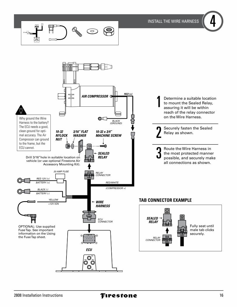
INSTALL THE WIRE HARNESS 4
SUP
AS-1 AS-2
EXH
SUP
AS-1 AS-2
EXH
ECU
RED (+)
20 AMP FUSE
RED 12V (+)
RED/WHITE
ECU CONNECTOR
RELAYCONNECTOR
(COMPRESSOR +)
BATTERY (+)
YELLOW
+12V IGN WIREHARNESS
BLACK (-)
BATTERY (-)
OPTIONAL: Use supplied Fuse Tap. See important information on the Usingthe Fuse Tap sheet.
BLACK(GROUND)
RED (+)AIR COMPRESSOR
SEALEDRELAYDrill 3/16”hole in suitable location on
vehicle (or use optional Firestone AirAccessory Mounting Kit).
10-32 x 3/4” MACHINE SCREW
10-32NYLOCK NUT
3/16” FLAT WASHER
1 Determine a suitable location to mount the Sealed Relay, assuring it will be within reach of the relay connector on the Wire Harness.
2 Securely fasten the Sealed Relay as shown.
3 Route the Wire Harness in the most protected manner possible, and securely make all connections as shown.
RELAYCONNECTOR
Fully seat until male tab clickssecurely.
SEALEDRELAY
TAB CONNECTOR EXAMPLE
Why ground the Wire Harness to the battery? The ECU needs a good, clean ground for opti-mal accuracy. The Air Compressor can ground to the frame, but the ECU cannot.
riderite.com17
SUP
AS-1 AS-2
EXH
SUP
AS-1 AS-2
EXH
ECU
1/8 NPT PUSH-TO-CONNECTSTRAIGHT FITTING
AIR LINE TUBE
AIR LINE TUBE
OPTIONAL: Install Air Line Tube to the EXHair fitting - 16” max. Route to SUP
on ECU.
Route to AS-1on ECU.
Route to AS-2on ECU.
Route to EXH on ECU.
AIR LINETUBE
LEFT AIR SPRING(when facing forward)
RIGHT AIR SPRING(when facing forward)
AIR COMPRESSOR
* As a water/debris trap. See page 4.
Createloop in AirLine Tube.
AIR SPRINGS(sold separately)
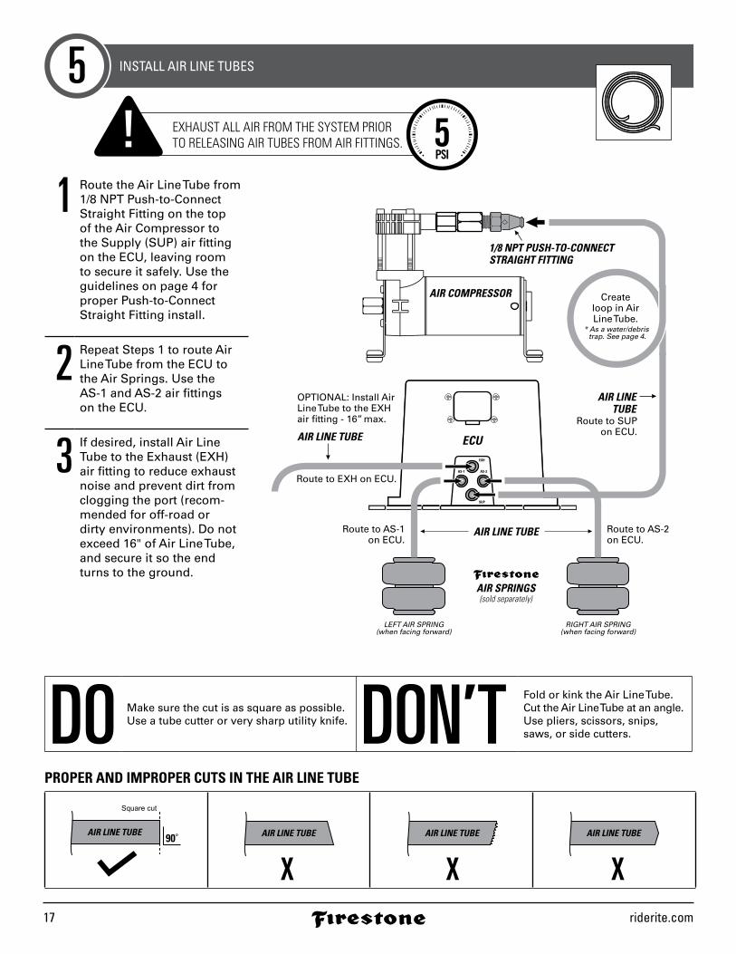
INSTALL AIR LINE TUBES5
DO Make sure the cut is as square as possible.Use a tube cutter or very sharp utility knife. DON’T Fold or kink the Air Line Tube.
Cut the Air Line Tube at an angle.Use pliers, scissors, snips,saws, or side cutters.
Square cut
90˚AIR LINE TUBE AIR LINE TUBE AIR LINE TUBE AIR LINE TUBE
PROPER AND IMPROPER CUTS IN THE AIR LINE TUBE
EXHAUST ALL AIR FROM THE SYSTEM PRIORTO RELEASING AIR TUBES FROM AIR FITTINGS. 5
PSI
1 Route the Air Line Tube from 1/8 NPT Push-to-Connect Straight Fitting on the top of the Air Compressor to the Supply (SUP) air fitting on the ECU, leaving room to secure it safely. Use the guidelines on page 4 for proper Push-to-Connect Straight Fitting install.
2 Repeat Steps 1 to route Air Line Tube from the ECU to the Air Springs. Use the AS-1 and AS-2 air fittings on the ECU.
3 If desired, install Air Line Tube to the Exhaust (EXH) air fitting to reduce exhaust noise and prevent dirt from clogging the port (recom-mended for off-road or dirty environments). Do not exceed 16" of Air Line Tube, and secure it so the end turns to the ground.
2808 Installation Instructions 18
AIR COMPRESSORAIR FILTERHand tighten.
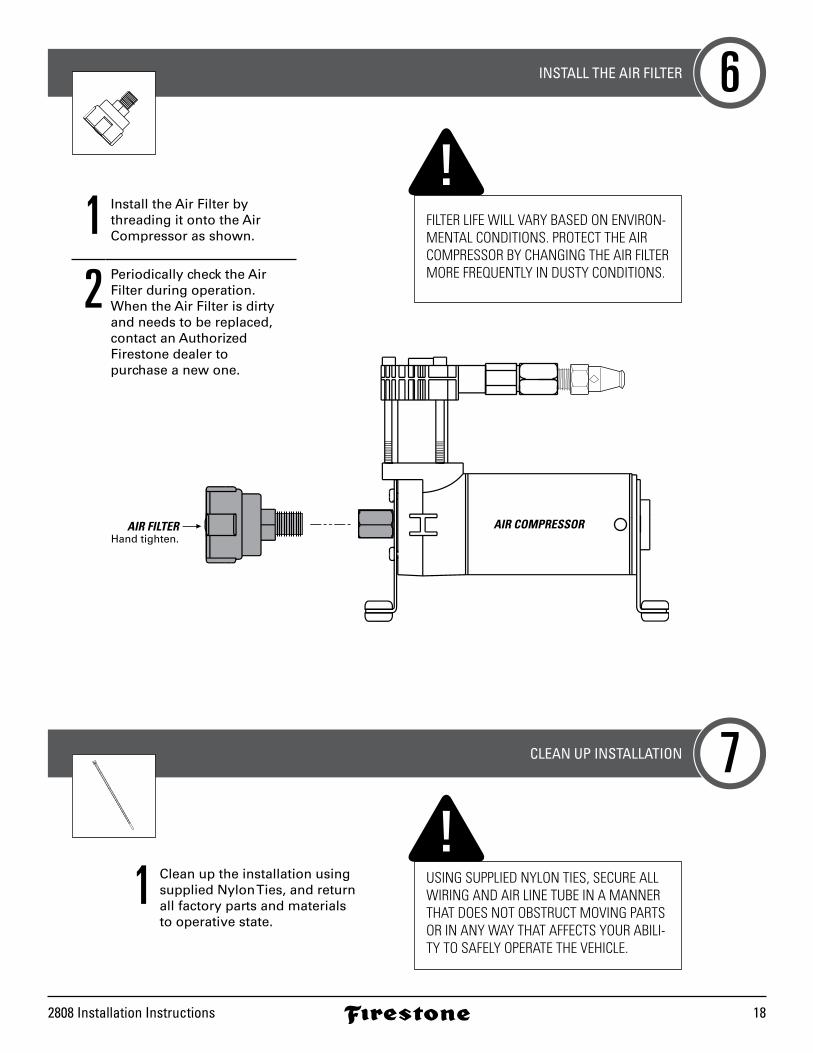
1 Install the Air Filter by threading it onto the Air Compressor as shown.
2 Periodically check the Air Filter during operation. When the Air Filter is dirty and needs to be replaced, contact an Authorized Firestone dealer to purchase a new one.
INSTALL THE AIR FILTER
CLEAN UP INSTALLATION
6
7
1 Clean up the installation using supplied Nylon Ties, and return all factory parts and materials to operative state.
USING SUPPLIED NYLON TIES, SECURE ALL WIRING AND AIR LINE TUBE IN A MANNER THAT DOES NOT OBSTRUCT MOVING PARTS OR IN ANY WAY THAT AFFECTS YOUR ABILI-TY TO SAFELY OPERATE THE VEHICLE.
FILTER LIFE WILL VARY BASED ON ENVIRON-MENTAL CONDITIONS. PROTECT THE AIR COMPRESSOR BY CHANGING THE AIR FILTER MORE FREQUENTLY IN DUSTY CONDITIONS.
riderite.com19
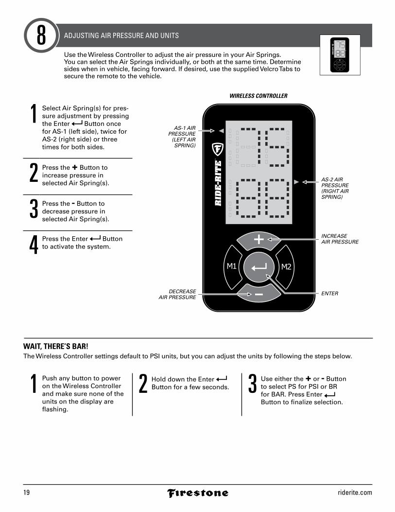
ADJUSTING AIR PRESSURE AND UNITS8
WIRELESS CONTROLLER
AS-1 AIRPRESSURE
(LEFT AIRSPRING)
AS-2 AIRPRESSURE(RIGHT AIR SPRING)
INCREASEAIR PRESSURE
ENTERDECREASEAIR PRESSURE
1 Select Air Spring(s) for pres-sure adjustment by pressing the Enter Button once for AS-1 (left side), twice for AS-2 (right side) or three times for both sides.
2 Press the + Button to increase pressure in selected Air Spring(s).
3 Press the - Button to decrease pressure in selected Air Spring(s).
4 Press the Enter Button to activate the system.
1 Push any button to power on the Wireless Controller and make sure none of the units on the display are flashing.
2 Hold down the Enter Button for a few seconds. 3 Use either the + or - Button
to select PS for PSI or BR for BAR. Press Enter Button to finalize selection.
Use the Wireless Controller to adjust the air pressure in your Air Springs. You can select the Air Springs individually, or both at the same time. Determine sides when in vehicle, facing forward. If desired, use the supplied Velcro Tabs to secure the remote to the vehicle.
WAIT, THERE’S BAR!The Wireless Controller settings default to PSI units, but you can adjust the units by following the steps below.
2808 Installation Instructions 20
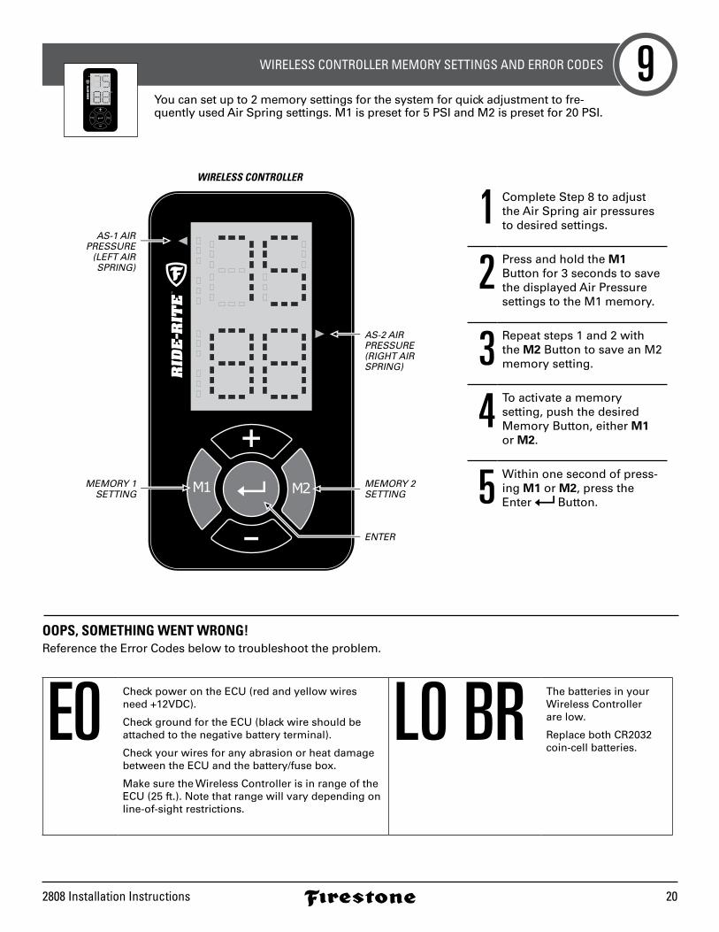
WIRELESS CONTROLLER MEMORY SETTINGS AND ERROR CODES 9
WIRELESS CONTROLLER
AS-1 AIRPRESSURE
(LEFT AIRSPRING)
AS-2 AIRPRESSURE(RIGHT AIR SPRING)
MEMORY 2SETTING
ENTER
MEMORY 1SETTING
1 Complete Step 8 to adjust the Air Spring air pressures to desired settings.
2 Press and hold the M1 Button for 3 seconds to save the displayed Air Pressure settings to the M1 memory.
3 Repeat steps 1 and 2 with the M2 Button to save an M2 memory setting.
4 To activate a memory setting, push the desired Memory Button, either M1 or M2.
5 Within one second of press-ing M1 or M2, press the Enter Button.
You can set up to 2 memory settings for the system for quick adjustment to fre-quently used Air Spring settings. M1 is preset for 5 PSI and M2 is preset for 20 PSI.
OOPS, SOMETHING WENT WRONG!Reference the Error Codes below to troubleshoot the problem.
E0 Check power on the ECU (red and yellow wires need +12VDC).
Check ground for the ECU (black wire should be attached to the negative battery terminal).
Check your wires for any abrasion or heat damage between the ECU and the battery/fuse box.
Make sure the Wireless Controller is in range of the ECU (25 ft.). Note that range will vary depending on line-of-sight restrictions.
L0 BR The batteries in your Wireless Controller are low.
Replace both CR2032 coin-cell batteries.
riderite.com21
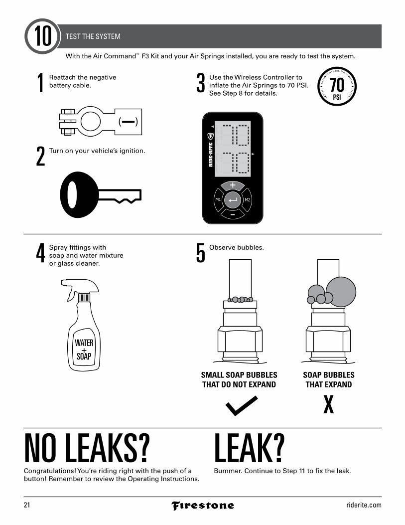
TEST THE SYSTEM10With the Air Command™ F3 Kit and your Air Springs installed, you are ready to test the system.
NO LEAKS?Congratulations! You’re riding right with the push of a button! Remember to review the Operating Instructions.
LEAK?Bummer. Continue to Step 11 to fix the leak.
1 Reattach the negative battery cable.
2 Turn on your vehicle’s ignition.
4 Spray fittings with soap and water mixture or glass cleaner. 5 Observe bubbles.
3 Use the Wireless Controller to inflate the Air Springs to 70 PSI. See Step 8 for details. 70
PSI
WATER+
SOAP
SMALL SOAP BUBBLESTHAT DO NOT EXPAND
SOAP BUBBLESTHAT EXPAND
2808 Installation Instructions 22
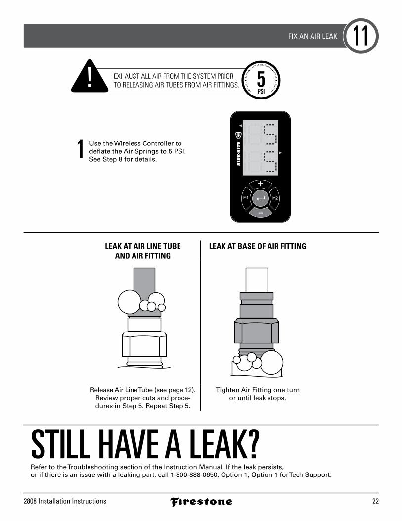
FIX AN AIR LEAK 11
STILL HAVE A LEAK?Refer to the Troubleshooting section of the Instruction Manual. If the leak persists, or if there is an issue with a leaking part, call 1-800-888-0650; Option 1; Option 1 for Tech Support.
LEAK AT AIR LINE TUBE AND AIR FITTING
LEAK AT BASE OF AIR FITTING
Release Air Line Tube (see page 12). Review proper cuts and proce-dures in Step 5. Repeat Step 5.
Tighten Air Fitting one turn or until leak stops.
1 Use the Wireless Controller to deflate the Air Springs to 5 PSI.See Step 8 for details.
EXHAUST ALL AIR FROM THE SYSTEM PRIORTO RELEASING AIR TUBES FROM AIR FITTINGS. 5
PSI
NEED INSTALLATION HELP? 1-800-888-0650Select Option 1 for Ride-Rite; Select Option 1 for Technical Support.
Or, email us at [email protected]. If emailing, please include photos to help us better diagnose and under-stand any problems you may be experiencing.
riderite.com
2808
12-15
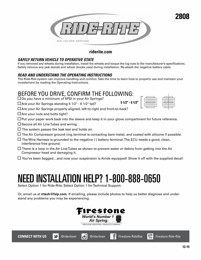
BEFORE YOU DRIVE, CONFIRM THE FOLLOWING: Do you have a minimum of 5PSI in your Air Springs?
Are your Air Springs standing 5 1/2" - 6 1/2" tall?
Are your Air Springs properly aligned, left-to-right and front-to-back?
Are your nuts and bolts tight?
Put your paper work back into the sleeve and keep it in your glove compartment for future reference.
Secure all Air Line Tubes and wiring.
The system passes the leak test and holds air.
The Air Compressor ground ring terminal is contacting bare metal, and coated with silicone if possible.
The Wire Harness is grounded to the negative (-) battery terminal. The ECU needs a good, clean, interference-free ground.
There is a loop in the Air Line Tubes as shown to prevent water or debris from getting into the Air Compressor head and damaging it.
You’ve been bagged…and now your suspension is Airide equipped! Show it off with the supplied decal!
5 1/2" - 6 1/2"
CONNECT WITH US @rideriteair @rideriteair Firestone RideRite Firestone Ride-Rite
SAFELY RETURN VEHICLE TO OPERATIVE STATEIf you removed any wheels during installation, install the wheels and torque the lug nuts to the manufacturer’s specifications. Safely remove any jack stands and wheel chocks used during installation. Re-attach the negative battery cable.
READ AND UNDERSTAND THE OPERATING INSTRUCTIONSThe Ride-Rite system can improve handling and comfort. Take the time to learn how to properly use and maintain your investement by reading the Operating Instructions.