air conditioning in commercial buildings
TRANSCRIPT

APPLICATION GUIDESI unit edition
AIR CONDITIONING IN COMMERCIAL BUILDINGS

ENERGY IN COMMERCIAL BUILDINGS .................................................................................................... 4 Where do we spend energy in a commercial building ? ............................................... 4 Impact of cooling systems on building energy use ......................................................... 5 Integrated design approach ........................................................................................................ 7AIR CONDITIONING IN COMMERCIAL BUILDINGS .......................................................................... 8 Types of air conditioning systems ............................................................................................ 9 Schematic of a central air conditioning plant ..................................................................10 Characteristics of an efficient chiller plant ........................................................................12 Energy split in central air conditioned plant .....................................................................13PUMPS IN CENTRAL AIR CONDITIONING PLANT ............................................................................15 Closed Loop Systems .....................................................................................................................16 Pump head calculation ................................................................................................................19 Open loop systems.........................................................................................................................23 NPSH consideration .......................................................................................................................24 Performance adjustment of centrifugal pumps .............................................................25PIPING SCHEMES ............................................................................................................................................29 Chilled water schemes .................................................................................................................29 Primary pumping system ...........................................................................................................30 Secondary pumping system ......................................................................................................30CONSTANT VOLUME CHILLED WATER SYSTEM ................................................................................31CONSTANT PRIMARY / VARIABLE SECONDARY SYSTEMS ............................................................35 De-coupler sizing ............................................................................................................................37 Chiller sequencing..........................................................................................................................39 Chiller staging ..................................................................................................................................42 Control valves and actuators ....................................................................................................43PRIMARY-SECONDARY-TERTIARY PUMPING SYSTEMS .................................................................46 Mixing loop controllers ................................................................................................................48 Tertiary zone with direct connection with distribution network ...........................49 Tertiary zone with in-direct connection with distribution network ......................50 Variable Primary Flow Systems, VPF ......................................................................................51 Design of VPF systems .................................................................................................................52VARIABLE PRIMARY PUMP SELECTION ..................................................................................................55 Control strategies ...........................................................................................................................56 Instrumentation & control ........................................................................................................56 Chiller sequencing..........................................................................................................................58 Bypass valve control ......................................................................................................................59 Application consideration of VPF systems .........................................................................60 Location of differential pressure sensor ..............................................................................62
CONTENT
32
PREFACE
Air conditioning or HVAC&R is an active and rapidly developing technology. Though the con-cept of air conditioning dates back to ancient Egypt, modern air conditioning concepts emerged from 19th century.
In today’s modern world, air conditioning has become a part of the daily life. And has a rela-tion to the living standard of the people too. In developing economies, air conditioning which was earlier termed as luxury has now become a necessity due to changing climatic conditions. People have started using air conditioning in their daily life and expect the same indoor comfort in the places they visit.
Further rapid urbanisation of the cities across the world has resulted in many new construc-tion projects where air conditioning has a wide use. As we know, air conditioning is normally the most energy intensive application in any establishment, be it a commercial or industrial process requirement.
With depleting energy resources across the globe, designing an energy efficient air condi-tioning system is of prime importance to any designer as it has huge cost bearing on the operating expenses of the building throughout its life cycle. This requires a holistic approach, starting from building orientation, selection of facade glasing, construction materials, shading, thermal mass, lighting etc.,
Srinivasa Rajkumar
Application Manager with Grundfos Commercial Building Services
How each individual sub system of an air conditioning plant can influence the perfor-mance of related sub systems are a must to understand the system performance in totality. With modern energy modelling tools available, a designer can optimize both passive and active designs of an air conditioning project to deliver an efficient air conditioning system.
Keeping view of the above, we have made an attempt to put together our decades of experience in air conditioning in more simple, understandable terms for the readers.
Hope this guide would give an insight into the world of air conditioning and the impact of the circulation systems in bringing energy efficiency.
Happy reading!

Energy composition split in a typical commercial building
Windows and glazing plays a significant role for a buildings energy consumption and indoor climate. The ideal glazing let through daylight and shuts out direct solar rays.
ENERGY IN COMMERCIAL BUILDINGS
54
ENERGY IN COMMERCIAL BUILDINGSToday’s building industry appears to be entering another era of change, with a view toward mini-mizing a different kind of footprint: the energy, carbon, and environmental footprint of com-mercial and residential buildings. Once again, change is being driven by a need to optimize and conserve resources — this time, clean air, water, and energy as well as land. As design-ers, developers, and owners search for ways to minimize the operating costs and environmen-tal impacts of buildings, while also increasing their functionality and appeal to occupants, “green” trends are becoming observable in the marketplace.
Where do we spend energy in a commercial building ?Energy use is the single largest operating expense in commercial office buildings, rep-resenting approximately one-third of typical operating budget. On an average 30-40% of energy in a commercial building is consumed by HVAC systems.
By becoming more energy efficient in HVAC, commercial buildings can reduce operating expenses, increase property asset value, and enhance the comfort of their tenants. They can also demonstrate their commitment to the environment by reducing pollution and the harmful greenhouse gas emissions that contrib-ute to global warming.
Impact of cooling systems on building energy useHeating, ventilation and air conditioning sys-tems account for the majority of money spent by a commercial building on energy. Even small adjustments to these systems can significantly improve the working environment and at the same time, save money.
There are several important factors that deter-mine the energy use of an HVAC System:
• Building envelope – The building envelope has a large influence on the hygrothermal performance of the building and its related energy consumption. By implementing an intelligent envelope design it is possible to drastically reduce the capacity of the cooling systems. The envelope should always be optimized for the given climatic conditions. To do so one needs to consider aspects such as insulation, materials, construction principles, weather statistics, user behaviour, comfort criteria etc.
• Building orientation - The building orienta-tion should be decided in coordination with the window and overall envelope design as these parameters are linked together. To reduce the incoming solar radiation, which often contributes with a major heat load, one needs to study the sunpaths at the given building loca-tion. North of the equator, buildings are most vulnerable to solar radiation from southern directions and vice versa on the southern side of the equator. East/west directions are often vulnerable in spring and autumn.
21% Plug load
21% Lighting
29% Heating
5% Ventilation
1% Water
heating
14% Cooling 9%
Other

Solar shading devices on a commercial building
Good indoor climate in office spaces is crutial to the working efficiency and employee satisfaction.
ENERGY IN COMMERCIAL BUILDINGS
76
• Building thermal mass - When speaking of thermal mass it is the utilization of thermal inertia in construction materials. High inertia (big thermal mass) introduces a higher diurnal heat capacity so that more excess heat may be stored deeper in the construction and thereby minimizing the cooling need. This has the result that room air temperature swings may be lowered compared to a room with low thermal mass, when exposed to high heat loads from e.g. solar radiation, people, equip-ment, lighting and transmission gains etc. Moreover, high thermal mass enables the possibility of cooling down constructions at night time, securing pleasant tempera-tures in the morning.
• Solar shading devices - Use of exterior shading devices such as overhangs, vertical fins and awnings reduces the heat ingress into the glasses and thereby reduces the heat load
• Analyse energy performance with energy simulation - Use energy simulation software and life cycle analysis tools to optimize the performance of all compo-nents of the building envelope
• Indoor air quality (IAQ) – More refined air quality consumes more energy. ASHRAE 62.1 standard specifies minimum ventila-tion rates and other measures intended to provide indoor air quality that is accept-able to human occupants and that mini-mizes adverse health effects.
• Internal heat loads – Heat generated by lighting, equipment and people contribute to the overall thermal load on the building. By utilizing more efficient lighting and equipment it is possible to reduce the necessary cooling capacity.
• Efficient chiller plant - Much energy is wasted in inefficient and badly maintained chillers. By ensuring intelligent design and adequate maintenance much energy may well be pre-served
• Controls - By monitoring the cooling system and plant status in a central building manage-ment system (BMS) it is possible to not only control the systems but also keep track of errors and possibly implement further optimi-zation to minimize energy consumption.
Integrated design approachIntegrated building design is a process of design in which decisions on HVAC design is made in coor-dination with decisions about the appearance and overall functionality of the building. This integrated approach employs design elements to capture waste heat, reduce material or energy use or reuse materi-als wherever possible.
But these integrated approaches in design of build-ings are impossible without a dedicated design team fully engaged and focussed on project goals from the beginning. So many aspects of design are interrelated and have to be considered simultane-ously to achieve a high performance HVAC system.
With all those factors affecting HVAC design – build-ing siting to building envelope composition, exterior wall construction, glazing, occupancy, day-lighting, lighting controls – its undeniable that an integrated building design approach is very much essential for delivering a high performance building.
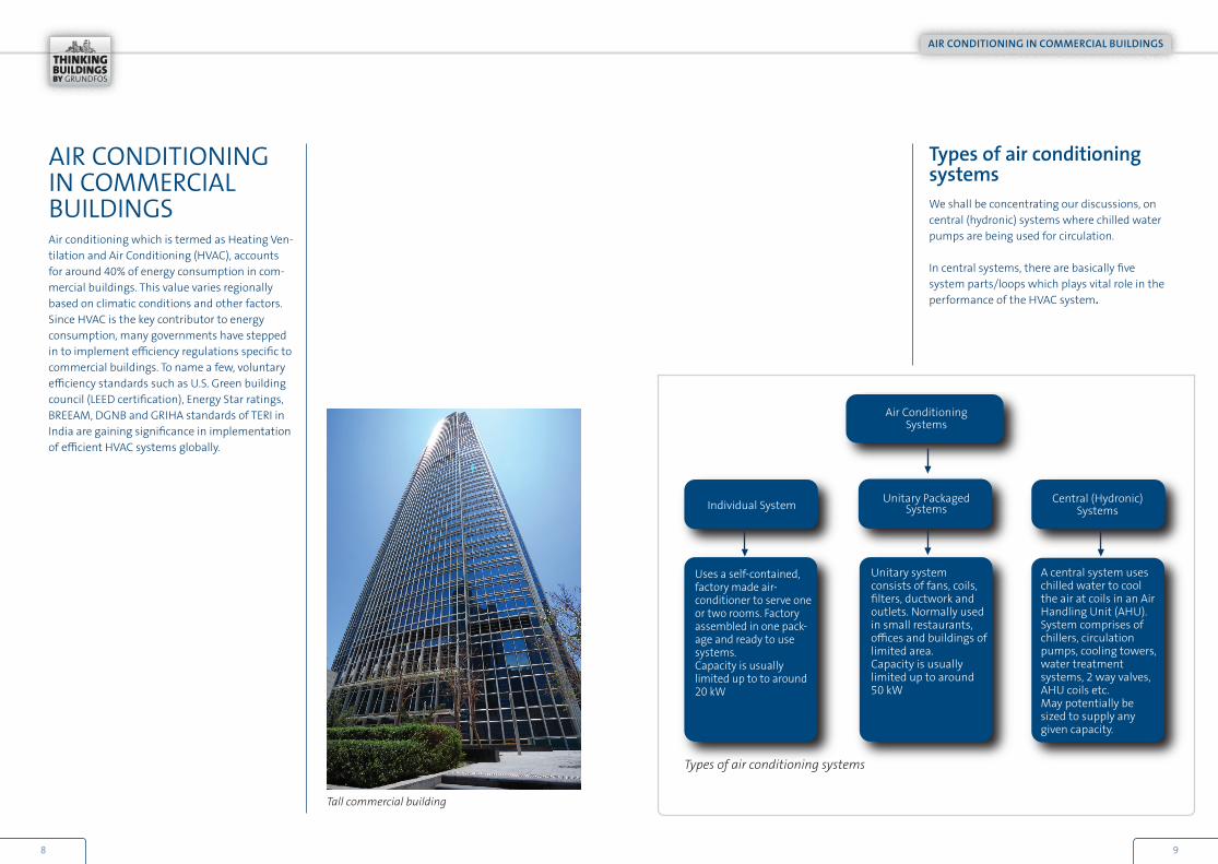
AIR CONDITIONING IN COMMERCIAL BUILDINGSAir conditioning which is termed as Heating Ven-tilation and Air Conditioning (HVAC), accounts for around 40% of energy consumption in com-mercial buildings. This value varies regionally based on climatic conditions and other factors. Since HVAC is the key contributor to energy consumption, many governments have stepped in to implement efficiency regulations specific to commercial buildings. To name a few, voluntary efficiency standards such as U.S. Green building council (LEED certification), Energy Star ratings, BREEAM, DGNB and GRIHA standards of TERI in India are gaining significance in implementation of efficient HVAC systems globally.
Types of air conditioning systemsWe shall be concentrating our discussions, on central (hydronic) systems where chilled water pumps are being used for circulation.
In central systems, there are basically five system parts/loops which plays vital role in the performance of the HVAC system.
Air Conditioning Systems
Individual System Unitary Packaged Systems
Central (Hydronic) Systems
Uses a self-contained, factory made air-conditioner to serve one or two rooms. Factory assembled in one pack-age and ready to use systems. Capacity is usually limited up to to around 20 kW
Unitary system consists of fans, coils, filters, ductwork and outlets. Normally used in small restaurants, offices and buildings of limited area.Capacity is usually limited up to around 50 kW
A central system uses chilled water to cool the air at coils in an Air Handling Unit (AHU). System comprises of chillers, circulation pumps, cooling towers, water treatment systems, 2 way valves, AHU coils etc. May potentially be sized to supply any given capacity.
Types of air conditioning systems
Tall commercial building
AIR CONDITIONING IN COMMERCIAL BUILDINGS
98

Schematic of a central air conditioning plant
A central system overall consists of the following five sub-systems, which are individual heat transferring loops of circulating water that is exchanged. The system is de-pictured below
• Refrigeration loop - Consists of chiller where in refrigerant changes its state at various stages to either absorb or reject heat from evaporator and condenser respectively
• Heat rejection loop - Consists of cooling towers, condenser water pumps and water treatment systems. This loop is to
reject the heat from the hot refrigerant into atmosphere either through radiators (in case of air cooled system) or through cooling towers wherein water carries away the heat from condenser coil and rejects the heat to the atmosphere.
• Chilled water loop - Consists of circulation pumps, which carries the cool water from the chiller to the various distribution sys-tems like Fan Coil Units (FCU) or Ceiling Suspended Units (CSU) or Air Handling Units (AHU) or Radiant Cooling Panels (RCP). Various distribution methods are employed to carry the chilled water to these distribution systems based on load demand, which shall be discussed in detail in further chapters
• Air side loop - Consists of low side (air side) distribution network like Fan Coil Units (FCU) or Ceiling Suspended Units (CSU) or Air Handling Units (AHU). Centrifugal fans are used in AHU’s which are VFD (Variable Frequency Drive) driven based temperature requirement of condi-tioned space.
• Controls loop - Which integrates the com-plete system to ensure that the design intent is ensured in the project. All the sub systems: Chillers, pumps, cooling towers, fan coil units, cooling tower fans, water treatment systems are all integrated into a single system for easy monitoring and control.
Buffertank
Scematic of a primary / secondary / tertiary chilled water system
AIR CONDITIONING IN COMMERCIAL BUILDINGS
1110
Heat recovery
Cooling surface
Cooling ceiling /floors
Fan colis
ChillerPrimary pump
Secondarypumps
Condenser pump
Tertiary pump
Tertiary pump
Tertiary pump
Pressureholding

Energy split in central air conditioned plantThe approximate distribution of energy con-sumption in a central air conditioning plant of a moderate capacity (<1800 kW) is given in below chart.
Possibilities of optimizing energy consumption of a central air conditioning plant lies mainly with chillers, fans and pumps in the order of their contribution. Modern chillers from renowned chiller manufacturers like Trane, Carrier, and York (to name a few) has evolved through these years and offer sophisticated designs delivering better energy performance over the past designs.
Variable speed chillers utilize more efficient operation by offering more adaptable chillers where compressor speed is varied vis-à-vis plant load. For example minimum full load effi-ciency (COP) for a 1800 kW centrifugal chiller was around 4.7 in the year 1998 whereas build-ing owners today are aiming towards a COP of 6.4 for the whole plant (including pumps, fans and ancillaries).
This is quite possible if we apply the concept of “integrated energy design”. Specifying high efficiency lighting, good glass and appropriate insulation materials reduces the cooling load for the building which translates into a small capacity, less expensive chiller providing good user comfort.
Energy split in a central air conditioning plant
2% Condenser
water pump2%
FCU’s4%
Misc
55% Chillers
33% Fans
3% Chilled
water pumps
1% Colling
tower fans
Characteristics of an efficient chiller plantA central system overall consists of the follow-ing five sub-systems, which are individual heat transferring loops of circulating water that is exchanged. The system is de-pictured below.
An efficient design concept - Selecting an appropriate design concept that is respon-sive to the changing operating conditions is essential in achieving efficiency. Variable flow pumping system for large campus applications, and selecting the quantity, type and configura-tion of chillers based upon the expected load profile are few of the factors influencing the efficient design
Efficient components - Chillers, pumps, fans and motors should all be selected for a stand-alone as well as systemic efficiency. Premium efficiency motors, pumps with high efficiency at the designed operating condition, chillers that are efficient at both full and partial loads are few examples
Proper installation, commissioning and opera-tion - A chiller plant that meets the first two criteria can still waste a lot of energy and provide poor comfort to building occupants, if not installed or operated properly.
AIR CONDITIONING IN COMMERCIAL BUILDINGS
1312
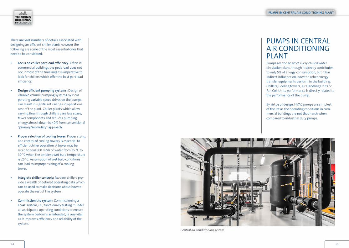
PUMPS IN CENTRAL AIR CONDITIONING PLANTPumps are the heart of every chilled water circulation plant, though it directly contributes to only 5% of energy consumption, but it has indirect influence on, how the other energy transfer equipments perform in the building. Chillers, Cooling towers, Air Handling Units or Fan Coil Units performance is directly related to the performance of the pump.
By virtue of design, HVAC pumps are simplest of the lot as the operating conditions in com-mercial buildings are not that harsh when compared to industrial duty pumps.
There are vast numbers of details associated with designing an efficient chiller plant; however the following are some of the most essential ones that need to be considered:
• Focus on chiller part load efficiency: Often in commercial buildings the peak load does not occur most of the time and it is imperative to look for chillers which offer the best part load efficiency.
• Design efficient pumping systems: Design of variable volume pumping systems by incor-porating variable speed drives on the pumps can result in significant savings in operational cost of the plant. Chiller plants which allow varying flow through chillers uses less space, fewer components and reduces pumping energy almost down to 40% from conventional “primary/secondary” approach.
• Proper selection of cooling tower: Proper sizing and control of cooling towers is essential to efficient chiller operation. A tower may be rated to cool 800 m3/h of water from 35 °C to 30 °C when the ambient wet bulb temperature is 26 °C. Assumption of wet bulb conditions can lead to improper sizing of a cooling tower.
• Integrate chiller controls: Modern chillers pro-vide a wealth of detailed operating data which can be used to make decisions about how to operate the rest of the system.
• Commission the system: Commissioning a HVAC system, i.e., functionally testing it under all anticipated operating conditions to ensure the system performs as intended, is very vital as it improves efficiency and reliability of the system.
Central air conditioning system
PUMPS IN CENTRAL AIR CONDITIONING PLANT
1514

Closed loop systemsA chilled water pumping scheme is normally a closed loop piping wherein entire pipe length is filled with water and the system is not open to atmosphere. Here, the static pressure exerted by the vertical column of pipe is equal on both the sides of pump. Circulation pumps need to only overcome the frictional losses in the piping and the associated components. It is not neces-sary for the pumps to “lift” the water from a lower level.
Here the circulation pump just needs to overcome the frictional resistance offered by the heat exchangers (chillers and cooling coils), pipes and valves. Vertical height of the pipes hardly affects the system resistance as it gets nullified by the static water column.
Care to be taken to size the pressure rating of the pump casing, pipes and associated compo-nents considering the static pressure when the system is non-operational. For normal pressure rating pump casings are selected with cast iron of PN 10 rating. For high rise buildings, ductile iron grade is preferred over cast iron for with-standing higher static pressures.For tall buildings of height more than 40 floors or like, multi stage pumping with an intermedi-ate service floor with a heat exchanger is highly recommended and practiced in HVAC industry.
By employing a heat exchanger in the service floor, the higher static pressure exerted on the plant room components such as pumps, chillers and its accessories are limited to normal PN 10 / PN 16 range. Also when pressure zones are isolated, the chilled water can be circulated in lower pressure levels, delivering operational cost savings too.
PUMPS IN CENTRAL AIR CONDITIONING PLANT
1716
Cooling coil
Circulation Pump
Circulation Pump
Circulation Pump
Expansion tank
Expansion tank
Expansion tank
Chiller Chiller
Cooling coil
Cooling coil
Cooling coil
Cooling coil
Heat Exchanger

Pump Flow calculation
Usually engineers design the cooling installation based on various design and site specific data. For example, after energy modelling of the building, designers arrive at a total of 26,000 kW of excess heat that is to be removed by 5 chillers. A chilled water supply temperature of around 7 °C and a return tem-perature of 12 °C are considered.
The heat transfer in the circulating water is calculated based on
Cooling capacity [kW] = density [kg/m3] x specific heat [kJ/kg K] x flow [m3/s] x (CHWR [K] – CHWS [K])
As a standard practice in HVAC industry, chilled water pumps are sized to feed water per chiller (i.e., one pump per chiller). Based on this, above flow can be considered as flow required per pump for circulating chilled water.
Heat load to be removed = 26,000 kW
Temperature difference (ΔT) = 12-7 °C = 5 °C
Number of working chillers = 5
Cooling capacity per chiller = 26,000 = 5,200 kW
Flow required per chiller = 5,200 kW
(1000 kg/m3 x 4.19 kJ/kg x 5 K)
Calculation: Hydraulic duty for the chilled water pumps
Pump head calculationTo arrive at the resistance offered by the system against the above calculated flow, pressure loss throughout the system has to be calculated.
In an air conditioning system, pressure loss is related to frictional resistance offered by pipes, pipe fittings, bends, valves, heat exchangers etc.,
Pipe fittings consist of elbows, tees, couplings, reducers and unions. These components may be screwed, welded or flanged to the pipes. Materials generally used here are steel. Cast iron, ductile iron, copper, brass, stainless steel or bronze.
Primary pumps in a chilled water system.
5
= 0.25 m3/s = 894 m3/h
PUMPS IN CENTRAL AIR CONDITIONING PLANT
1918

Pipe Sizing: Single line diagram of an air conditioning circulation system Calculation: Frictional losses in supply lines
1 A
B OC
D2
3E
F
G
IJ
K
L
M
H
5
6
7
Chiller
4
Consider above diagram to calculate the necessary flow in the cooling system supplying the air conditioning.
Air Handling Unit 1 = 100 kW Air Handling Unit 2 = 200 kW Air Handling Unit 3 = 150 kW Air Handling Unit 4 = 80 kWAir Handling Unit 5 = 120 kWAir Handling Unit 6 = 200 kW Air Handling Unit 7 = 150 kW Total cooling capacity (chiller) = 1,000 kW
Temperature difference (ΔT) = 5.5 °C
1,000 kW
Still considering the above diagram the fictional loss in the supply lines is taken into account.
Design velocity = 2.4 m/sPipe material = Black Steel Pipe of Schedule 40 Longest loop distance = A-B-C-D-E-F-G-6
The frictional pressure loss gradient (Pa/m) in the supply pipes may be estimated based on pressure
loss diagrams from literature, e.g. ASHRAE Handbook – Fundamentals (Figure 4, chapter 22).
Supply side
Sections Flow (m3/h)
Length (m)
Frictional loss (Pa/m)
Total Frictional loss (kPa)
Pipe dia (mm)
AB 156 21 350 7.2 154
BC 133 20 200 3.9 154
CD 117 64 410 11.0 154
DE 86 14 500 3.4 128
EF 62 11 600 1.4 128
FG 50 15 300 3.7 102
G6 31 12 900 4.7 102
Total frictional loss
35.3
(1000 kg/m3 x 4.19 kJ/kg x 5.5 K)= 0.04 m3/s = 156 m3/hFlow required for the system =
PUMPS IN CENTRAL AIR CONDITIONING PLANT
2120
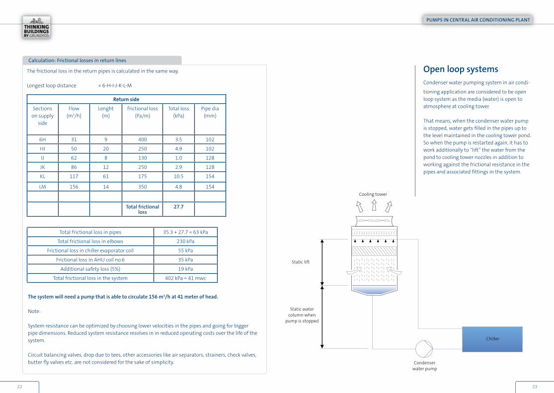
Calculation: Frictional losses in return lines
The frictional loss in the return pipes is calculated in the same way.
Longest loop distance = 6-H-I-J-K-L-M
The system will need a pump that is able to circulate 156 m3/h at 41 meter of head.
Note:
System resistance can be optimized by choosing lower velocities in the pipes and going for bigger pipe dimensions. Reduced system resistance resolves in in reduced operating costs over the life of the system.
Circuit balancing valves, drop due to tees, other accessories like air separators, strainers, check valves, butter fly valves etc. are not considered for the sake of simplicity.
Return side
Sections on supply
side
Flow (m3/h)
Lenght (m)
frictional loss (Pa/m)
Total loss(kPa)
Pipe dia (mm)
6H 31 9 400 3.5 102
HI 50 20 250 4.9 102
IJ 62 8 130 1.0 128
JK 86 12 250 2.9 128
KL 117 61 175 10.5 154
LM 156 14 350 4.8 154
Total frictional loss
27.7
Total frictional loss in pipes 35.3 + 27.7 = 63 kPa
Total frictional loss in elbows 230 kPa
Frictional loss in chiller evaporator coil 55 kPa
Frictional loss in AHU coil no.6 35 kPa
Additional safety loss (5%) 19 kPa
Total frictional loss in the system 402 kPa = 41 mwc
Open loop systemsCondenser water pumping system in air condi-
tioning application are considered to be open loop system as the media (water) is open to atmosphere at cooling tower.
That means, when the condenser water pump is stopped, water gets filled in the pipes up to the level maintained in the cooling tower pond. So when the pump is restarted again, it has to work additionally to “lift” the water from the pond to cooling tower nozzles in addition to working against the frictional resistance in the pipes and associated fittings in the system.
PUMPS IN CENTRAL AIR CONDITIONING PLANT
2322
Chiller
Cooling tower
Condenser water pump
Static lift
Static water column when
pump is stopped

NPSH considerationFor open loop systems like condenser water pumping systems, NPSH (Net Positive Suction Head) available at site has to be kept suffi-ciently more than the required for the pump duty, by designing the piping system. NPSH available is supplied from the system and it is solely a function of the system design on the suction side of the pump.
To avoid cavitation, the NPSH available from the system must be greater than the NPSH required by the pump.
NPSHa = Ha + Hs – Hvp – Hf
Where,
Ha = the head on the surface of the liquid in the tank / sump. I.e.., atmospheric pressure
Hs = the vertical distance of the free surface of the liquid above the centre line of the impeller. If the liquid is below the pump centre line, this value becomes negative.
Hvp = the vapour pressure of liquid at the pumping temperature,
Hf = the friction losses in the suction piping
Performance adjustment of centrifugal pumpsWhile selecting a pump for a given duty, it is important to choose one where the duty point is in the high efficiency area of the pump.
However, many times it is not possible to select a pump that fits the right duty point because the system requirements are dynamic with changes in the load pattern of the building. Therefore, it is necessary that the pumping system adjust its performance to meet the changes in the load pattern of the building.
The most common methods of changing pump performance are displayed on the right.
Any of the methods of pump performance adjustment is employed based on the initial investment together with the operating costs of the pump. Each of the methods has its own pros and cons which are discussed in further pages of this guide
Variable frequency drive, VFD
PUMPS IN CENTRAL AIR CONDITIONING PLANT
2524
Hs
Hf
Hs

Examples of pump throttelig valves. The valve below is provided with measuring nipples for flow verification.
Pump throttling
When a pump is sized for a system require-ment, the system head is estimated on various parameters. Sometimes, the estimated values of frictional resistance may not exist at the installation; leading to pump’s operating point shifting to right side of the curve. This leads to inefficient performance of the pump, consum-ing more power than required.
A throttle valve placed at the discharge side of the pump assists adjustment of duty point to system requirement.
The throttle valve adds resistance to the system and raises the systemcurve to a higher position. Without this addi-tional resistance the pump will run in extreme right side of the curve delivering a flow Q3.
By introducing a resistance HV from the throttle valve, resistance is added to the system which enables the pump to deliver the required flow of Q1. When such type of pump performance adjustment is done, the pump will deliver a higher head than the one required for that particular system.
PUMPS IN CENTRAL AIR CONDITIONING PLANT
2726
Q1
Pump curve
Resulting charateristic
curve System curve
Throttle curve
Q
Smaller pump curve
Q2
Hs
Hv
Q3
H
Change in pump performance when Impeller diameter is changed.
Impeller
Hn
HX DX
Dn
Q
H
Impeller trimming
Another way of adjusting the pump perfor-mance of a centrifugal pump is changing the impeller diameter – meaning reducing the impeller diameter which reduces the pump hydraulic performance.
Impeller trimming is governed by affinity laws and is given by following formulae:
• Flow, Q α Diameter of impeller, D• Head, H α Diameter of impeller, D2
• Power, P α Diameter of impeller, D3
Please note that impeller trimming will have an effect on pump efficiency too. For minor changes of the impeller diameter, pump effi-ciency is reduced only by few percentages. The degree of efficiency reduction depends on pump type and duty point (Do check specific pump curves for finer details)
Impeller diameter changes are generally limited to reducing the diameter to about 75% of maxi-mum i.e., a head reduction to about 50%. Beyond this, efficiency and NPSH are badly affected. For example, reducing speed by 50% typically results in a reduction of pump efficiency by 1 or 2 percentage points.
Qn nn Hn nn Pn nn
Qx nx Hx nx Px nx
Please note that affinity laws apply on a condi-tion that the system characteristic remains unchanged for nn and nx and form a parabola through the origin.
= = =( ( ))2 3
Qx
Hn
Hx
Qn
nn
nn
nx
nx
nnnx
Pn
Px
PIPING SCHEMES
2928
Q
Q
Q
H
H
H
Cooling load
Secondary pump
Distribution loop
De-
coul
per
Production loop
Primary pump
Chill
er
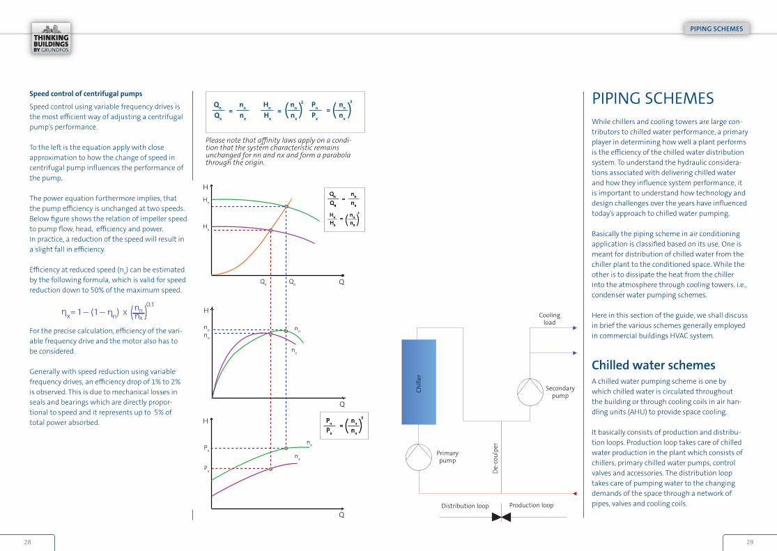
PIPING SCHEMES While chillers and cooling towers are large con-tributors to chilled water performance, a primary player in determining how well a plant performs is the efficiency of the chilled water distribution system. To understand the hydraulic considera-tions associated with delivering chilled water and how they influence system performance, it is important to understand how technology and design challenges over the years have influenced today’s approach to chilled water pumping.
Basically the piping scheme in air conditioning application is classified based on its use. One is meant for distribution of chilled water from the chiller plant to the conditioned space. While the other is to dissipate the heat from the chiller into the atmosphere through cooling towers. i.e., condenser water pumping schemes.
Here in this section of the guide, we shall discuss in brief the various schemes generally employed in commercial buildings HVAC system.
Chilled water schemesA chilled water pumping scheme is one by which chilled water is circulated throughout the building or through cooling coils in air han-dling units (AHU) to provide space cooling.
It basically consists of production and distribu-tion loops. Production loop takes care of chilled water production in the plant which consists of chillers, primary chilled water pumps, control valves and accessories. The distribution loop takes care of pumping water to the changing demands of the space through a network of pipes, valves and cooling coils.
Speed control of centrifugal pumps
Speed control using variable frequency drives is the most efficient way of adjusting a centrifugal pump’s performance.
To the left is the equation apply with close approximation to how the change of speed in centrifugal pump influences the performance of the pump.
The power equation furthermore implies, that the pump efficiency is unchanged at two speeds.Below figure shows the relation of impeller speed to pump flow, head, efficiency and power. In practice, a reduction of the speed will result in a slight fall in efficiency.
Efficiency at reduced speed (nx) can be estimated by the following formula, which is valid for speed reduction down to 50% of the maximum speed.
For the precise calculation, efficiency of the vari-able frequency drive and the motor also has to be considered.
Generally with speed reduction using variable frequency drives, an efficiency drop of 1% to 2% is observed. This is due to mechanical losses in seals and bearings which are directly propor-tional to speed and it represents up to 5% of total power absorbed.
Chilled water pumps in a secondary loop
CONSTANT VOLUME CHILLED WATER SYSTEM
3130
Primary pumping systemThe main objective of the primary pump is to circulate chilled water within the production loop. This pump is typically located anywhere (either upstream or downstream of the chiller), provided the pump satisfies the following conditions:
• Maintains the minimum dynamic pressure head (inlet pressure) at heat exchangers (evaporator coil) at chiller. If the recommended inlet pressure is not high enough at these com-ponents, proper flow will not be established through them
• Accommodates the total pressure (static plus dynamic head) on system components such as chiller’ s evaporator, valves etc.,
• Meets the minimum net positive suction head requirements. That is the system inlet pressure at the pump must be positive and high enough for the pump to operate properly
Secondary pumping systemHere the main objective to distribute the chilled water to the various cooling coils overcoming the frictional resistance offered by the pipes, valves and bends in the entire network.
The distribution system may contain other com-ponents such as expansion tanks, control valves, balancing valves, check valves, air separators etc.
Hydraulic selection of these pumps, are discussed in our chapters which can be refereed for selection of these pumps.
These pumps are usually configured in headered fashion, for system redundancy.
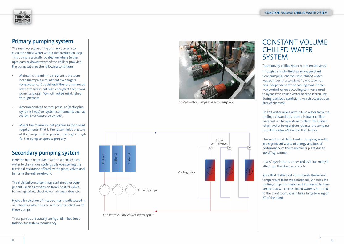
CONSTANT VOLUME CHILLED WATER SYSTEMTraditionally, chilled water has been delivered
through a simple direct-primary, constant flow pumping scheme. Here, chilled water was pumped at a constant flow rate which was independent of the cooling load. Three way control valves at cooling coils were used to bypass the chilled water back to return line, during part load conditions, which occurs op to 80% of the time.
Chilled water mixes with return water from the cooling coils and this results in lower chilled water return temperature to plant. This lower return water temperature reduces the tempera-ture differential (ΔT) across the chillers.
This method of chilled water pumping, results in a significant waste of energy and loss of performance of the main chiller plant due to low ΔT syndrome.
Low ΔT syndrome is undesired as it has many ill effects on the plant as a whole.
Note that chillers will control only the leaving temperature from evaporator coil, whereas the cooling coil performance will influence the tem-perature at which the chilled water is returned to the plant room, which has a large bearing on ΔT of the plant.
Constant volume chilled water system
Chill
er -1
Chill
er -2
Chill
er -3
Primary pumps
Cooling loads
3 waycontrol valves

Example: Impact of low delta-T (ΔT) syndrome 1
Low ΔT is a serious problem for constant flow system because it drastically reduces installed chiller capacity in the plant.
For example, if chiller is receiving return water temperature of 11 °C instead of designed 13 °C, the chiller loading will be,
CHWTR - CWSTD x 100 CWRTD – CWSTD
Where,
CHRTR = Actual chilled water return temperature
CWSTD = Design chilled water supply temperature
CWRTD = Design chilled water return temperature
Applying the values in the above equation, 11-7CHL – Chiller loading in % = x 100 = 67% 13 – 7
Because of 2 °C reduction in chilled water return temperature from design, chiller capacity gets reduced by around 30%.
Say for example the plant has a 3,500 kW capacity chiller, a 2 °C reduced return temperature lowers the actual cooling capacity to only 2,333 kW.
To overcome this capacity deficiency, plant operators start extra chillers and connected pumps to provide the needed capacity. This increases the plant usage to cool the building, thereby consum-ing extra energy to produce the same cooling effect.
CHL – Chiller loading in % =
Example: Impact of low delta-T (ΔT) syndrome 2 (Full load situation)
Chiller capacity = 3x 850 kWDesigned supply water temperature = 7 °CDesigned return water temperature = 13 °CTemperature difference (ΔT) = 6 °C
850 kW (1000 kg/m3 x 4.19 kJ/kg x 6 K)
Chill
er -1
Chill
er -2
Chill
er -3
At full load condition, the designed conditions will prevail and 3 way valves will not bypass any chilled water through the bypass line. All the chilled water will flow through the cooling coils, entering at 7 °C and leaving the load at 13 °C.
Required flow per pump = = 0.03 m3/s = 122 m3/h per pump
3332
CONSTANT VOLUME CHILLED WATER SYSTEM
Design Supply temperature 7 °C
Design Return temperature 13 °C
Required flow per pump– 122 m3/h per pump
3 waycontrol valves
Chiller capacity 2,550 kW

Designed supply water temperature = 7 °CActual return water temperature = 10 °CTemperature difference (ΔT) = 3 °C
Chiller capacity reduced to = 0.03 m3/s x 1000 kg/m3 x 4.19 kJ/kg x 3 K = 425 kW (50% reduction)
Hence, for meeting a building load of 850 kW, now 2 chillers needs to be run instead of one, resulting in extra energy spent on one extra chiller and pump. Additional chillers and pumps increase a plant’s energy usage. Added to this, chillers operating at part load are less efficient than those at full load.
With the advent of more efficient technologies in control valves and plant controls, this type of system is not used anymore. Older systems with 3 way valves are being retrofitted with 2 way valves and more efficient variable secondary chilled water systems.
Example: Impact of low delta-T (ΔT) syndrome 3 (Part load situation)
Chill
er -1
Chill
er -2
Chill
er -3
Design Supply temperature 7 °C
Design Return temperature 10 °C
Required flow per pump– 122 m3/h per pump
3 waycontrol valves
Chiller capacity – reduces to
1,275 kW(3x425kW)
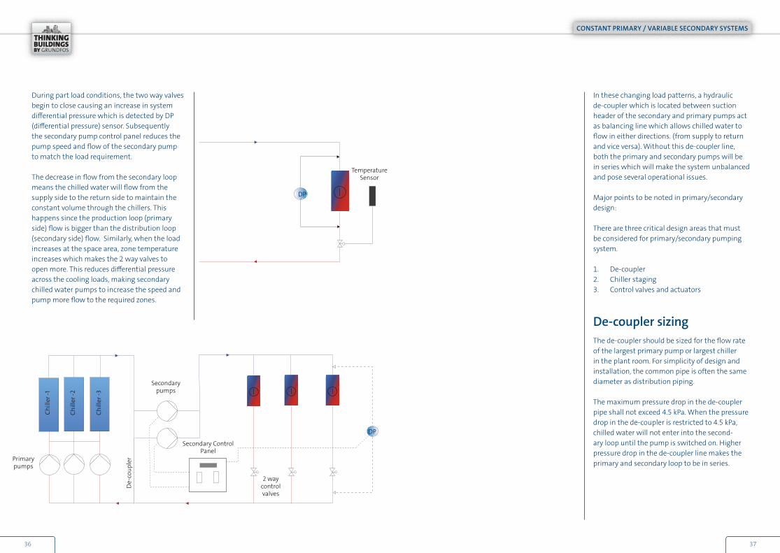
CONSTANT PRIMARY / VARIABLE SECONDARY SYSTEMSA primary-secondary pumping scheme divides the chilled water system into two distinct circuits that are hydraulically separated by a de-coupler (neutral bridge).
In primary/secondary systems, chilled water flows through the chiller primary loop at a constant flow rate, whereas in secondary loop, flow rate is varied using a control system. The hydraulic independ-ence of each loop prevents variable flow in the secondary loop from influencing the constant flow in the primary loop.
Each loop includes a set of pumps sized to deliver the same flow rate against the individual total dynamic head. Primary pumps are constant speed pumps delivering constant volume in the production loop, and the secondary pumps are of variable speed delivering variable volume match-ing the load requirement. This allows the chillers to receive a constant chilled water flow, while the distribution system flow can vary to match load.
Speed of the secondary pumps are determined by the controller measuring differential pressure (DP) across the supply and return mains of the chilled water loop or across the most critical load in the pipe network.
Primary – secondary variable flow systems are more efficient than constant flow systems, because they allow the secondary pump to use only the energy as necessary to meet the system demand. Unnecessary pumping is avoided in distribution bringing in energy efficiency in these systems.
3534
CONSTANT PRIMARY / VARIABLE SECONDARY SYSTEMS
Primary pumps
De-
coup
ler
Secondary pumps
Temperature Sensor
Secondary Control Panel
2 waycontrol valves
DP
DP
Chill
er -1
Chill
er -2
Chill
er -3
In these changing load patterns, a hydraulic de-coupler which is located between suction header of the secondary and primary pumps act as balancing line which allows chilled water to flow in either directions. (from supply to return and vice versa). Without this de-coupler line, both the primary and secondary pumps will be in series which will make the system unbalanced and pose several operational issues.
Major points to be noted in primary/secondary design:
There are three critical design areas that must be considered for primary/secondary pumping system.
1. De-coupler2. Chiller staging3. Control valves and actuators
De-coupler sizingThe de-coupler should be sized for the flow rate of the largest primary pump or largest chiller in the plant room. For simplicity of design and installation, the common pipe is often the same diameter as distribution piping.
The maximum pressure drop in the de-coupler pipe shall not exceed 4.5 kPa. When the pressure drop in the de-coupler is restricted to 4.5 kPa, chilled water will not enter into the second-ary loop until the pump is switched on. Higher pressure drop in the de-coupler line makes the primary and secondary loop to be in series.
During part load conditions, the two way valves begin to close causing an increase in system differential pressure which is detected by DP (differential pressure) sensor. Subsequently the secondary pump control panel reduces the pump speed and flow of the secondary pump to match the load requirement.
The decrease in flow from the secondary loop means the chilled water will flow from the supply side to the return side to maintain the constant volume through the chillers. This happens since the production loop (primary side) flow is bigger than the distribution loop (secondary side) flow. Similarly, when the load increases at the space area, zone temperature increases which makes the 2 way valves to open more. This reduces differential pressure across the cooling loads, making secondary chilled water pumps to increase the speed and pump more flow to the required zones.
3736
CONSTANT PRIMARY / VARIABLE SECONDARY SYSTEMS

Distance between the T- joints between secondary and primary headers where this de-coupler line is located must be at least of 3 pipe diameters. Lengthy pipes may result in excessive pressure drop greater than 4.5 kPa resulting in adverse effects as indicated above.
Length of de-coupler T-joint from the first chiller should be of minimum 10 pipe diam-eters to avoid possibility of stratification in the chilled water return line header. Since the temperature transmitters are fixed close to these, proper lengths are to be provided for proper mixing and correct temperature reading to avoid chiller cycling.
De-
coup
ler
Secondary pumps
Minimum 3D length
2 waycontrol valves
Chill
er -1
Chill
er -2
Chill
er -3
Chiller sequencingProper chiller sequencing plays an important role in the overall performance of a primary/second¬ary pumping systems. There are three conditions which are encoun-tered in day-to-day operation of these systems as given below:
1. Primary flow equals secondary flow 2. Secondary flow is greater than primary flow 3. Primary flow is greater than secondary flow
Primary flow equals secondary flow The chiller is delivering 300 m3/h (0.08 m3/s) with a supply and return temperature of 7 °C and 13 °C respec-tively to the cooling coils. The cooling capacity embed-ded in the water is:
0.08 m3/s x 1000 kg/m3 x 4.19 kJ/kg K x 6 K = 2,095 kW
When the delivered capacity equals the needed capac-ity in the cooling coils, the system becomes thermally balanced and hence there is no flow in the de-coupler line. This condition however, rarely occurs and there is always a flow in the de-coupler line in some direction or the other.
on
on
off off
offChill
er -3
Chill
er -2
Chill
er -1
offoffon
Primary/secondary system with equal flow
3938
Primary pumps
300 m3/h @ 7 °C 300 m3/h @ 7 °C
Supply side
No flow through the common pipe
300 m3/h @ 13 °C 300 m3/h @ 13 °C
CONSTANT PRIMARY / VARIABLE SECONDARY SYSTEMS

Secondary flow is greater than primary flow
Consider the below case wherein, the secondary side cooling demand increases from 2,095 kW to 2,795 kW and the two-way valves in the secondary circuit opens up in response to increase the flow rate from 300 to 400 m3/h (0.11 m3/s). With only one chiller operating at 2,095 kW, the excess 100 m3/h will pass through the de-coupler line. With this 100 m3/h flow passing through de-coupler line at 13 °C, the resultant temperature at the supply header becomes 400 m3/h at 8.5 °C after mixing with 100 m3/h at 7 °C. It is not possible to increase the cooling capacity by increasing the flow rate in the secondary circuit alone.
A higher secondary supply water temperature to coils hinders the ability to provide dehumidification that means loss of humidity control in the second¬ary zones. To reduce the supply temperature to the coils and thereby increase the cooling capacity, operators immedi-ately start next chiller resulting in primary flows greater than secondary. In general, flow in the reverse primary direction in a de-coupler line should be prevented.
on offoff
Chill
er -3
Chill
er -2
Chill
er -1
offoffon
Primary flow is greater than secondary flow
Starting another chiller to reduce the supply temperature, the total flow on the primary side becomes 600 m3/h. As a reaction to this, the two-way valves at the cooling coils are opened to let through the additional flow until the required cooling capacity of 2,795 kW has been achieved. The resultant water flow becomes 400 m3/h with a temperature difference across the cooling coils of 6 °C. However, due to the 600 m3/h primary flow, there will be an excess flow of 200 m3/h in the de-coupler. Here, 200 m3/h at 7 °C from the supply side mixes with the 400 m3/h at 13 °C from the coils, resulting in a flow of 600 m3/h at 11 °C. This is lower than the desired return water temperature of 13 °C and thus makes the plant delta T to go down from 6 to 4 °C, thereby reducing the installed chiller capacity by 33 %. Out of the 2,095 kW each of the two chillers should be delivering; they will only be producing 1,397 kW each thereby meeting the cooling need of 2,795 kW together due to the effect of low ΔT syndrome.
on offon
Mixing 200 m3/h @ 7 °C+ 400 m3/h @ 13 °C = 600 m3/h @ 11 °C
Supply side
Chill
er -3
Chill
er -2
Chill
er -1
offonon
600 m3/h @ 7 °C
200 m3/h @ 7 °C
400 m3/h @ 7 °C
600 m3/h @ 11 °C 400 m3/h @ 13 °C
4140
300 m3/h @ 7 °C 400 m3/h @ 8.5 °C
Supply side
300 m3/h @ 13 °C
100 m3/h @ 13 °C
400 m3/h @ 13 °C
CONSTANT PRIMARY / VARIABLE SECONDARY SYSTEMS

Chiller stagingOperator’s main objective is to maintain the chiller leaving temperature at design. For this the operational strategy of the chiller plant should be based on the total chiller power and its related auxiliary power.
Chiller staging strategies require comparison of chiller capacity with the building cooling load. This can be done in the following ways:
1. Chilled water leaving temperature from the evaporator is an indication of plant capacity when it remains above setpoint for a specified length of time.
2. Flow direction in the de-coupler line is an indication of plant capacity. The tempera-ture in the de-coupler line can also do the job as well.
3. Calculation of load from measurements of flow and temperature can be useful for staging the chillers.
4. Measurement of current drawn by the chiller compressor motor can also give an indication to stage the chillers
Principally, the designer has to decide which strategy to be adopted to deliver the necessary performance of the plant by accommodating suitable chiller staging strategy.
Control valves and actuatorsControl valves and actuators play a vital role in the performance of a variable secondary pumping application. The load change in the space area is measured by DP sensor, andthe control valves are required to vary the water flow through the cooling coils in rela-tion to change in building cooling demand. Characteristics of these control valves are to be clearly understood so that they are selected properly.
Control valves in a mixing loop arrangement in a chilled water system. Only the actuators are visible
4342
CONSTANT PRIMARY / VARIABLE SECONDARY SYSTEMS

Quick opening type
Linear type valve
Equal percentage valve
Influence of control valve selection on variable pumping systems
Proper sizing of control valves is critical in a vari-able volume pumping system. Oversized control valves cause the controller to “hunt”, alterna-tively opening and closing the valve resulting in flow in the system higher than the designed, thereby reducing the delta T.Valves are selected to operate against a differ-ential pressure across its inlet and outlet ports. This pressure drop across the valve varies with its opening. To size the valve correctly, it is necessary to know the pressure drop when full flow passes through the valve.
An electric actuator is connected to the valve stem and the selection of these actuators is also critical to the performance of the air condition-ing system. Close-off rating is the maximum differential pressure across the valve against which the valve and actuator can completely close. Dynamic close-off pressure rating is the maximum differential pressure for modulating applications, above this stated pressure rating, control through the entire stroke is no longer smooth and the design turn down ratio will not be achieved.
Often valves are selected only to achieve the required close off rating, but they cannot provide modulating duty under high differential pres-sures. The end result is hunting of the valves, and poor temperature control of the system.On the other hand if a secondary pump control system, for any reason operates at higher dif-ferential pressure than the designed, it may influ-ence the performance of these control valves. And in the long run, these valves may lose its controllability, if subjected to higher differential pressure from the pump control system.
Flow characteristics of a control valve
Valves control the flow of fluids, through move-ment of an actuator. A stem with a plug moves along with the actuator, this plug seats within the valve port and against the valve seat with a composition disc or metal-to-metal seating. Based on the property of the plug, valves are classified into 3 distinct types:
• Quick opening type• Linear type valve• Equal percentage valve
Quick opening typeWhen started from the closed position, a quick opening valve allows a considerable amount of flow to pass for small stem travel.Amount of stem travel and flow share a non-linear relationship in this type of valve.Used in on/off or two position applications.
Linear type valveLinear control valves deliver equal increments for each step the stem travels.Used in steam coil terminals and in the bypass port of 3 way or mixing valves.
Equal percentage valveAs the name indicates, this type of valve delivers equal percentage increase in flow for equal increments of stem travel. Used in flow control of hot and cold water supply applications.
4544
CONSTANT PRIMARY / VARIABLE SECONDARY SYSTEMS
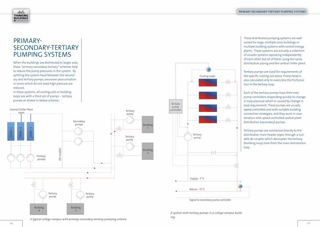
PRIMARY-SECONDARY-TERTIARY PUMPING SYSTEMSWhen the buildings are distributed to larger area, these “primary-secondary-tertiary” schemes help to reduce the pump pressures in the system. By splitting the system head between the second-ary and tertiary pumps, excessive pressurization in zones which do not need high pressure are reduced.In these systems, all cooling coils or building loops are with a third set of pumps – tertiary pumps as shown in below scheme.
A typical college campus with primary-secondary-tertiary pumping scheme
Chill
er -1
Chill
er -2
Chill
er -3
A system with tertiary pumps in a college campus build-ing.
These distributed pumping systems are well suited for large, multiple zone buildings or multiple building systems with central energy plants. These systems are actually a collection of smaller systems operating independently of each other but all of them using the same distribution piping and the central chiller plant.
Tertiary pumps are sized for requirements of the specific cooling coil alone. Pump head is also calculated only to overcome the frictional loss in the tertiary loop.
Each of the tertiary pumps have their own pump controllers responding quickly to change in loop pressure which is caused by change in load requirement. These pumps are usually speed controlled and with suitable building connection strategies, and they work in coor-dination with speed controlled central plant distribution (secondary) pumps.
Tertiary pumps are connected directly to the distribution main header pipes through a suit-able de-coupler which decouples the tertiary (building loop) zone from the main distribution loop.
4746
Secondary pumps
De-
coup
ler
Central Chiller Plant room
Tertiary pump
Tertiary pump
Tertiary pump
Tertiary pump
Building 4
Building 3
Building 2
Building 1
Primary pumps
PRIMARY-SECONDARY-TERTIARY PUMPING SYSTEMS
Tertiary pump
controller
Tertiary pump
ΔP
ΔP
Return - 13 °C
Supply - 7 °C
Cooling loads
Signal to secondary pump controller
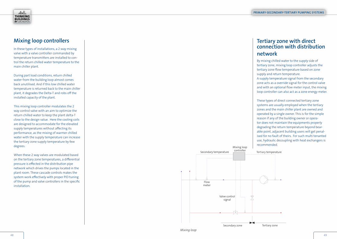
Mixing loop controllersIn these types of installations, a 2 way mixing valve with a valve controller commanded by temperature transmitters are installed to con-trol the return chilled water temperature to the main chiller plant.
During part load conditions, return chilled water from the building loop almost comes back unutilised. And if this low chilled water temperature is returned back to the main chiller plant, it degrades the Delta-T and robs off the installed capacity of the plant.
This mixing loop controller modulates the 2 way control valve with an aim to optimize the return chilled water to keep the plant delta-T close to the design value. Here the cooling coils are designed to accommodate for the elevated supply temperatures without affecting its performance, as the mixing of warmer chilled water with the supply temperature can increase the tertiary zone supply temperature by few degrees.
When these 2 way valves are modulated based on the tertiary zone temperatures, a differential pressure is effected in the distribution pipe network which drives the pumps located in the plant room. These cascade controls makes the system work effectively with proper PID tuning of the pump and valve controllers in the specific installation.
Mixing loop controllerSecondary temperature
Valve control signal
Tertiary temperature
Flowmeter
Tertiary zoneSecondary zone
Mixing loop
Tertiary zone with direct connection with distribution networkBy mixing chilled water to the supply side of tertiary zone, mixing loop controller adjusts the tertiary zone flow temperature based on zone supply and return temperature.A supply temperature signal from the secondary zone acts as a override signal for the control valve and with an optional flow meter input, the mixing loop controller can also act as a zone energy meter.
These types of direct connected tertiary zone systems are usually employed when the tertiary zones and the main chiller plant are owned and operated by a single owner. This is for the simple reason if any of the building owner or opera-tor does not maintain the equipments properly degrading the return temperature beyond bear-able point, adjacent building users will get penal-ised for no fault of theirs. For such multi tenanted use, hydraulic decoupling with heat exchangers is recommended.
4948
PRIMARY-SECONDARY-TERTIARY PUMPING SYSTEMS

Flowmeter
Mixing loop controller
Tertiary zoneSecondary zone
Secondary temperature
Valve control signal
HeatExchanger
Tertiary temperature
Tertiary zone with in-direct connection with distribution networkThe main purpose of employing a heat exchanger in between the distribution network and the tertiary zone is,
1. Static pressure requirements of each of the buildings can be addressed locally within the building
2. Water quality / Delta T degradation of indi-vidual buildings does not affect another
3. For better hydraulic decoupling
Logic of mixing loop controller remains the same for indirect connection except for the change in location of the 2 way mixing valve. An optional flow meter input, gives load data on each of these tertiary zones. All the meas-ured parameters from mixing loop controllers are relayed to central building management system.
Exchange units set-up
Mixing loop systems are specifically used for large campus systems and are beneficial during part load con-ditions wherein the return temperature is utilised in the tertiary zones without compromising user comfort.
Variable Primary Flow Systems, VPFWhy we should use Variable Primary Flow Systems?
• Low energy cost due to variable flow (Chilled water is pumped only to the requirement of the load)
• Reduced operating cost• Better ability to tolerate below design chilled water
temperature differentials• Less capital cost, since secondary pumps and its
accessories are eliminated altogether
With the advent of more sophisticated control systems and improvement in chiller technology over the past few decades, variable primary flow systems are widely used now, in the air conditioning industry. It has a first cost savings straight away, as it eliminates secondary distribution pumps, associated pipes & accessories from the circuit.
Chill
er -1
Chill
er -2
Chill
er -3
Flow meters
Minimum flowbypass valve
normally closed
2way controlvalves
Cooling loads
De-
coup
ler
Primary pumps
5150
PRIMARY-SECONDARY-TERTIARY PUMPING SYSTEMS

There are certain limitations within which VPF sys-tems has to be designed.
Design limitations of variable primary flow systems
• Chiller manufacturers recommend a safe minimum flow beyond which flow should not be reduced
• Velocity of flow through evaporator to be main-tained between 1 to 3 m/s (varies between manufacturers) to contain tube erosion
• Rate of change of flow through the chiller should be as described by the respective chiller manufacturer
• Chillers in parallel configuration are to be of equal capacity
• System should be tolerant on temperature variations
Design of VPF systemsFlow and velocity limitationsEvery chiller manufacturer recommends the mini-mum flow range which can be pumped through the evaporator coil. Turn down ratio depends on chiller type also. Normally the minimum evaporator coil flow is 40 to 60% of the design flow. Any operation of the chiller less than the safe mini-mum flow will result in ice formation in the tubes leading to tube burst potentially damaging the whole equipment itself.Low velocity limits of 1 m/s, is to prevent laminar flow and also to keep the evaporator tubes clean. High velocity limit of 3 m/s is to avoid evaporator tube erosion.
Here the primary pump is sized for circulating chilled water through the chiller evaporator coil and further to the cooling coil loads. These pumps are equipped with variable frequency drives to vary the flow within the system to meet the operating conditions.
PRIMARY-SECONDARY-TERTIARY PUMPING SYSTEMS
Rate of change of chilled water flow
Since the flow through the evaporator coils are varied, there is a limit to the rate of change of flow as any abrupt change can cause instability in chiller controls and may lead to tripping of the chiller.
Normally the rate of change of flow is suggested by chiller manufacturers to limit the change between 2% per minute to 30% per minute depending on chiller type, controls and system turn- around time. Vapour compression chillers are generally capable of accommodating larger flow variations than equivalent absorption chillers.
Significance of system turn over time in VPF systems
It is the time required to circulate one system volume at the system flow rate. It is a measure of the system water mass relative to cooling load. It indicates how temperature change will affect the system. Longer turnover times increase the stability of chiller control to variations in load.
Chillers in VPF systems
Generally, chillers are selected based on the base load and the duty profile of the building.
For the simplicity of minimum flow monitoring and control, it is suggested that equal capacity chillers is selected in VPF systems. Dissimilar chillers will give different pressure drop values to the pump controller which makes difficult for deciding level of minimum flow required in a parallel operation.
Chiller unit with plate heat evaporator and condenser.
5352

Minimum flow bypass valve
In VPF systems, the bypass valve in common line is generally closed to allow the variable speed primary pumps to cater to load requirement directly. But when the cooling load requirement falls to a level where the necessary flow is less than the safe minimum flow that needs to be pumping through the evaporator coils (as per chiller manufacturer’s recommendation), there is excess pumping involved in the chiller plant.
In such a scenario, the amount of flow that is in excess to the cooling load requirement needs to be bypassed back to the chiller plant. Only in such instances, bypass valve opens up propor-tionately to divert the volume of chilled water back to the chiller plant.
Selection of bypass valve
Selecting an appropriate valve actuator is critical to ensure the proper functioning of the bypass function. One which maintains a linear relation-ship between the valve position and flow rate will do.
Can bypass valves be avoided in VPF systems ?
Yes, if the building load does not fall to a level lower than the chiller safe minimum flow as suggested by chiller manufacturers. I.e., the base load of the building stays well above.
VARIABLE PRIMARY PUMP SELECTIONWith constant flow chillers, pumps are usually selected at the design flow of the chiller evapo-rator coils. In VPF systems, pumps are slightly oversized, that is:
• To take advantage of the chiller’ s ability to provide additional capacity when the condenser water temperature is lower than the design
• To improve loading when the return chilled water temperature is lower than the design (i.e., during low Delta-T condi-tion)
The extent of flow over pumping depends on the ratio of maximum allowable velocity divided by design velocity. If the maximum allowable velocity is 3.0 m/s and the design velocity is 2.4 m/s, then percentage of over-pumping allowed is 3.0/2.4 or 125%.
Variable primary controllers shall have the features to evoke these functionalities at these load conditions to utilize the advantages, which improves the overall efficiency of the chiller plant.
With regards to pump head, variable primary pump head is usually high as there is no sepa-rate distribution pump in this scheme. Because of the high total dynamic head produced by single set of variable primary pump, due care must be given while sizing pressure rating of hydronic pipes and valves at pump shut off condition.
VARIABLE PRIMARY PUMP SELECTION
5554

Control strategiesControl of variable primary flow systems require more attention, so that chillers are not inadvert-ently shut down during simultaneous flow and load changes.
Avoiding transient flows during chiller staging is one of the main challenges while designing control strategies in a VPF system. Care should be given when selecting control programs and field instruments to avoid these situations which will be detrimental to the plant operation, if occurs.
Instrumentation & controlInteroperability of systems in VPF schemes is the key to its success. Sub systems of the chiller plant should be able to communicate between each other and to the central building manage-ment system to effectively deliver designed plant efficiency.
Flow meters, temperature transmitters, differ-ential pressure sensors all should effectively com-municate to the pump controllers which are very critical for the system performance.
For flow measurement, there are two ways which are commonly practised.
1. Use high accuracy magnetic flow meters in line with the evaporator coils for fast and accurate measurements. But for large size pipe diameters, these flow meters become relatively expensive.
VARIABLE PRIMARY PUMP SELECTION
Flow meters
2 way controlvalves Cooling loads
Variable speed pumps
Chiller -3
Chiller -1
Chiller -2
2. Another method is to use a rather inex-pensive differential pressure transmitter across the evaporator coil to measure the differential pressure through the coil which is a function of flow through it. Then this signal is related to flow signal by comparing with the published flow-pres-sure data from the chiller manufacturer.
Feedback from the valves at chiller isolation is very much needed for the controller to interlock the various functions and to stall the functions if there is any failure in the valve operation. Slow acting valves should be used at chillers to avoid surges in the system, while valve is in operation. This time bound operation of these valves reduces transient flows in the system.
5756

Chiller sequencingWhen plant operators want to bring in a second chiller into the system, the isolation valve of the second chiller is opened by the plant control system; this reduces the evaporator coil flow of the active first chiller, putting it into a greater risk of freezing. Because of the condition that first chiller is in full refrigerant load and at 50% of evaporator coil flow, which effectively doubles the chilled water temperature difference. This can force the chiller into a protective shut down.
Solution is to effectively unload the active chiller by imposing a demand limit of 50~60% or by raising the chilled water setpoint one to three minutes before isolation valve actuates.
Centrifugal chillers with tube and shell evaporator and condensers.
VARIABLE PRIMARY PUMP SELECTION
Flowmeters
75 m3/h
50 m3/h
25 m3/hBypass valve
2way controlvalves
Cooling loads
Only one Chiller is working Minimum flow- 75 m3/h
Variable speed pumps
Chiller -3
Chiller -2
Chiller -1
off
off
off
off
on
on
Bypass valve controlWhen the cooling loads are reducing, a point comes where the active chiller reaches it safe minimum flow which is much greater than what is needed at the cooling coils.
Closing of 2 way valves at cooling coils makes the dif-ferential pressure to increase in the system, but since the pump flow is limited by chiller safe minimum flow, the increase in pressure makes the pump operat-ing point to shift to its left. If the excess flow is not diverted in the bypass line, due to drop in flow, system might trip owing to low flow condition.
For example, say if the cooling coils need only 50 m3/h whereas the minimum safe recommended evapora-tor coil flow in the active chiller itself is 75 m3/h, the excess 25 m3/h is diverted through bypass line.
5958

Application consideration of VPF systemsIt is evident that variable primary flow systems are far more efficient when compared to constant primary/variable secondary system as there is no excess pumping involved. Apart from this operational advantage, there is a clear advantage on capital investment as well.
However, a variable primary flow application is more likely to be successful and economically beneficial under the following circumstances:
• Cooling load varies and loads are con-trolled by 2-way modulating valves. A 50% reduction in system flow can reduce pumping power by 80%
• Slight variations in supply water tempera-ture are acceptable. When staging in next chiller in sequence, supply water tempera-ture to building loads are allowed to rise a bit for a stable plant operation. (This is the reason variable primary flow systems are not suitable for process cooling applica-tion)
• Low flow measurement instrumentation are maintained and calibrated periodically. Flow measurement is most critical in VPF systems and accuracy of plant controls are lost if the flow is not known properly
• Operators know the system better and are conversant with its operations to derive the benefits of variable primary flow system design
VARIABLE PRIMARY PUMP SELECTION
CHW system type Primary / secondary Variable flow, primary-only
CHW pumps Two sets of low head pumps One set of high head pumps
Services for constant flow chiller pumps
Pipe/fittings, electrical service, control wiring, and starter
NA
Variable frequency drives (VFDs) for CHW
pumps
VFDs and electrical service for distribution pumps
VFDs and electri-cal service for larger
pumps
Bypass/de-coupler line Sized for the design flow of the largest chiller
Sized for the minimum flow of the largest
chiller
Bypass control valve NA Modulating control valve
Flow measurement NA Flow meter (or ΔP sensors)
Mechanical room space Space required for two sets of low head pumps
Space required for one set of high head
pumps
Primary – secondary systems still remains “the workhorse of the air conditioning industry”, a simple system for the operators to understand and maintain. Whereas variable primary flow systems, though it gives flexibility in providing chilled water where it is needed in the most efficient manner, it is more complex to imple-ment and requires understanding of operators to maintain it in the way it is designed.
But with the advancement in the intelligent controls and smart buildings, variable primary flow will pick up momentum in the years to come.
Primary / secondary and variable flow comparison
6160

Location of differential pressure sensorLocation of differential pressure sensor is critical in the performance of variable volume pump-ing system be it primary/secondary or variable primary flow system. Only if the DP sensor is located at the most critical zones, it can sense the load changes effectively to modulate the distribution pumps.
Location of the sensor is influenced by the pres-sure gradient as shown in the below schematic.
For direct return piping scheme like the one shown below, load closest to the plant having the shortest path will experience entire pump head. Pressure drop is minimal near to the plant and it is substantial at the end of the piping. Here balancing valves are required to ensure right flow to each circuit.
Cooling loads
Variable speed pumps
ΔP
ΔPcontrol valve
ΔPSecondary
pump
VARIABLE PRIMARY PUMP SELECTION
For reverse return piping scheme, pressure drop is theoretically the same across all load points due to equal length of piping from the chiller plant to the cooling loads. Pressure drop is nearly the same from the plant to the end of the piping.
Decision to use direct return or reverse return piping is based on system operability vs first cost, and it is left to the designer and the owner to decide.
Single DP sensor or multiple sensors?Always there is a question on whether to use single sensor in the system or need to use multiple sensor to ascertain the load changes.One DP sensor is good enough for closed loop application as change in load affects complete piping system and if the DP sensor is located cor-rectly then it can sense the load changes.
When a larger number of sensors are used unnec-essarily in the smaller piping system, too many sensing points increase the scan time and at any point of time, if one or the other sensor is having a deviation from the set point, the pump controller will try to respond – making the system unstable. Key is to avoid too many sensors, have either one or maximum two in the system and locate it properly in the piping network.
Cooling loads
Variable speed pumps
Wet/wet differential pressure sensor with pres-sure nipples.
6362
ΔP

APPLICATION GUIDE
AIR CONDITIONING IN COMMERCIAL BUILDINGS
GRUNDFOS Holding A/SPoul Due Jensens Vej 7DK-8850 BjerringbroTel: +45 87 50 14 00www.grundfos.com
VISIT US ONLINE For more information on Grundfos Commercial Building Services and
our services, please visit www.thinkingbuildings.com
Here, you can read all about our products or use our online tools, including the timesaving Quick
Pump Selection tool.