air brake & train handling...100.7 charging air brake system charge the air brake system to...
TRANSCRIPT

Air Brake & Train
Handling Rules
Effective March 25, 2019
AIR BRAKE & TRAIN
HANDLING RULES
TABLE OF CONTENTS
100.0 Train Air Brake Tests and Inspections 5100.1 Compliance with FRA and Transport Canada Regulations 5100.2 Safety Inspection of Freight Cars 5100.3 Coupling and Securing Air Hoses 6100.4 Operative Brakes - US Only 6100.5 Person in Charge of Air Brake Test 7100.6 Standard Brake Pipe Pressures 7100.7 Charging Air Brake System 7100.8 Air Brake Tests Using End-of-Train Telemetry Devices (ETD) Continuity Tests 7100.8.1 Air Brake Tests Using Handheld Gauges 8100.9 Brake Pipe Leakage Test 8100.10 Initial Terminal and Road Air Brake Test (Class 1 Air Brake Test) Canadian Class 1 Brake Testand Class 1-A Brake Tests 9100.11 Transfer Train Movements Test – United States 12100.12 Transfer Movements – Canada 13100.13 Running Air Brake Test 13100.14 Air Brake Test When Cutting Off and Recoupling 14100.15 Application and Release Test (Class 3 Air Brake Test) United States and Canada 14100.16 Air Brake Test When Adding Pre-Tested Cars 14100.17 Inbound Train Inspection 14100.18 Piston Travel Limits 15100.19 Dynamic Brake Requirements 15100.20 Inoperative Dynamic Brake on Lead, Controlling Locomotive 15
101.0 Locomotive Air Brake Tests and Inspections 16101.1 General Requirements 16101.2 Locomotive Daily Inspection 16101.3 Defects Other Than Non-Complying Conditions 20101.4 Non-Complying Condition Found En Route 21101.5 Major Internal Defects Found En Route 21101.6 Locomotive Air Brake Test 22101.7 Standard Air Pressures 23101.8 Reducing Locomotive Overcharge 23101.9 Control Switches 23101.10 Locomotive Safety Devices 23101.11 Operative Speed Indicator 24101.12 Event Recorder 24101.13 Moving Locomotive 24101.14 Moving Light Locomotive Consists 26101.15 Locomotive Air Brake Equipment 26101.16 Separating Locomotives 26101.17 Locomotives Equipped for Multiple-Unit Operation 26101.18 Locomotives Not Equipped for Multiple-Unit Operation 27101.19 Changing Operating Ends 28

3
102.0 Train Operations29102.1 Securing Equipment Against Undesired Movement 29102.2 Releasing Hand Brakes 31102.3 Unattended Locomotive(s) 31102.4 Brakes Not Operating Properly 32102.5 Sticking Brakes 32102.6 Reducing Pressure in Overcharged Train Brake Systems 32102.7 Cutting Out Air Brake Equipment 32102.8 Reporting Flat Spots 33102.9 Setting Out Defective Cars 34102.10 Coupling Brake Pipe Connections 34102.11 Powered Axle Limitation 35102.12 Helpers 35102.13 End of Train Telemetry System 37102.14 Emergency Application Capability from Rear of Train 39102.15 Running Air Brake Test 41102.16 Dynamic Brake Warning Light 41102.17 Unusual Conditions 41102.18 Train Separation Report 42102.19 Locomotive Operation – Heavy Snow 42102.20 Control of Harmonic Roll on Jointed Track 42102.21 Equipment Restrictions 42102.22 Snow Plow & Spreader Restrictions 43102.23 Car Weight 43Do not move or accept in interchange cars in excess of 263,000 pounds without authorization fromthe RTC or a supervisor 43102.24 Train Make Up 43102.25 Operation into Snow/Ice Covered Tracks 44102.26 Emergency Stop or Severe Slack Action 44
103.0 Train Handling 45103.1 Train Status Information 45103.2 Dynamic Braking 45103.3 Use of Automatic Brake 46103.4 Throttle Handling 47103.5 Independent Brake (Locomotive Brake) 49103.6 Train Handling Scenarios 49103.7 Grade Operation 55103.8 Emergency Brake Applications 57103.9 Unintentional Brake Release 58103.10 Penalty Brake Application 58103.11 Switching Movements 59103.12 Temporary Speed Restrictions 59
104.0 Freight Car and Locomotive Components and Charts60
104.1 Freight Car End and Platform Identification 60104.2 Wheel and Journal Identification on Cars 60104.3 Coupler Assemblies 60104.4 Freight Car A-1 Reduction Relay Valve 60104.5 Freight Car Automatic Vent Valve 61104.6 Retaining Valves 61104.7 Locomotive Brake Equipment 61104.10 Air Flow Meter 65104.11 Charging Time Chart 66
4
104.12 Electronic Alertness Device 66104.13 Over-speed Control 66104.14 Reserved 67104.15 Defect Detectors 67
106.0 Fuel Conservation 70106.1 Regulating Horsepower 70106.2 Isolating or Shutting Down Locomotives En Route 70106.3 Shut Down Requirement for Locomotives Not Being Utilized 70106.4 Shut Down Procedures 71106.5 Locomotive Starting 71106.6 Cold Weather Protection for Locomotives Not Equipped with AESS or APUs 72106.7 Speed Reduction for Fuel Conservation 73106.8 Movement of Light Engines and Caboose Only Moves 73
Glossary 74

5
100.0 Train Air Brake Tests and Inspections
100.1 Compliance with FRA and Transport Canada RegulationsInspect and test brake equipment on locomotives and cars according to Federal RailroadAdministration (FRA) regulations contained within these rules. In Canada comply withTransport Canada regulations.
Trains destined through to the United States from Canada must have received a brake testas per US regulations.
Trains destined through to Canada from the United States must comply with additionalCanadian regulations in addition to the US requirements.
Trains operating entirely in one country will comply with that country’s requirements.
Inspections when required, must be performed on both sides at some point during aninspection and air brake test to be able to examine and observe the functioning of allmoving parts of the brake system on each car as necessary, as well as to comply with allparts of 100.2. Roll-by inspections may only be utilized to determine that all brakes havereleased and may not be used to perform all other inspection requirements for either sideof the train.
100.2 Safety Inspection of Freight CarsPerform a safety inspection on all cars at the initial terminal or that are added en route asfollows:
Either, a “Qualified Person” or a “Qualified Mechanical Inspector” may perform inspectionsand air brake tests.
- A “Qualified Person” refers to a trainman given fundamental training on freight carinspections and air brake tests.
- A “Qualified Mechanical Inspector” or “Certified Car Inspector” refers to a personsuch as carman who has been given more extensive training that provides for amore detailed inspection.
Each car placed in the train may be moved after it receives a safety inspection as follows:
Cars must be checked for:
- Leaning.
- Sagging.
- Improper position on the truck.
- Objects hanging or dragging from the car or extending from the side.
- Insecurely attached doors.
- Broken or missing safety appliances.
- Contents leaking from placarded hazardous material car.
- Insecure coupling device.
- Overheated wheel or journal.
- Broken or cracked wheel.
- Brake that fails to release.
- Staff type brake not in fully raised position.
6
- Any apparent hazard that could cause an accident.
Open top loads, including trailers and containers on flat cars, must be loaded safely.
If width or height approaches clearance restrictions, movement must be cleared with theproper authority.
- A freight car with any defect that makes movement unsafe must be corrected or setout of the train.
- A freight car with three bad order tags indicating that the car is safe to move may bemoved to the nearest car repair point. The conductor will remove one bad ordertag from the side with two tags. The conductor will use this written informationfrom the tag to inform other crew members of the restrictions.
100.3 Coupling and Securing Air HosesBefore coupling air hoses between locomotives and/or cars, employees must:
• Shake debris out of the hoses.
• Blow all condensation from the locomotive brake pipe or yard air line.
Whenever possible, secure air hoses on locomotives and cars during all movements toprevent the hoses and glad-hands from dragging and becoming damaged.
100.4 Operative Brakes - US OnlyThese requirements apply to air brake tests and inspections:
• Unless brakes fail en route, air brakes on all cars must be operative unless being movedfor repairs and properly tagged. Qualified Mechanical Inspectors will provide three tags oncars given to train crews to be moved to repair facilities. Cars with defective air brakeequipment will be tagged on each side and the third tag will be retained on locomotive. Thisinformation may also be provided in train documentation. Tags will only be required on oneside of the car and on the locomotive when no crossover platform is available to crossoverbetween cars or when adjacent tracks are involved which could present risk of injury.EXCEPTION: Scale test cars are not required to be equipped with air brakes, but ifequipped must be operable.
• Cars discovered with brakes that fail en route must be tagged on both sides of the car andnoted on space provided on train documentation and left in controlling locomotive cab formholder for relieving crew. Tags will only be required on one side of the car and traindocumentation noted when no crossover platform is available to crossover between cars orwhen adjacent tracks are involved which could present risk of injury. (Reference ABTHRules 102.7 and 102.9 on procedures for handling cars with cut out air brakes.) Tags mustinclude the following information: (the back of locomotive defect tags provided onlocomotives or in crew packs may be used if no defective air brake tags are available).
Reporting Mark and Number of the defective locomotive or car
Name of the inspecting or discovering Railroad
Name and Job Title of Inspector
Inspection Location and Date
Type of Defect
Movement Restrictions
Repair Destination
Signature

7
• Train documentation may also reflect such cars by electronic means to subsequentcrews after defective brakes are initially discovered and reported.
At least 85 percent of the cars in a train must have operative brakes under allcircumstances.
When departing terminals, engineers must allow their trains to be inspected where required.
100.4.1 Operative Brakes – Canada• At Safety Inspection Locations, where No. 1 test is performed by a Certified Car
Inspector, 95% of brakes must be operable.
• At non-Safety Inspection Locations, where No. 1, 1-a, No 2 or No 3 tests are made,85% of brakes shall be operable.
• En route, trains requiring a brake test must have no less than 85% operable brakesat any time.
100.5 Person in Charge of Air Brake TestThe person performing the air brake test is in charge of the train while the test is beingconducted. Before permission is given to apply or release the brakes, the person in chargemust determine that all employees are safely positioned.
The employee at the controls of the locomotive must not apply or release train brakeswithout permission from the person performing the air brake test.
100.6 Standard Brake Pipe PressuresRegulating valve must be set as follows:
· Yard or Freight service - 90 psi
· Trains consisting entirely of business car or passenger equipment - 105 psi.
100.7 Charging Air Brake SystemCharge the air brake system to ensure that the system functions as needed. Whencharging the system:
· Do not charge a train’s air brake system with more than one automatic brake valve cutin.
· Do not increase diesel engine RPM to maintain main reservoir pressure unless thepressure fails to stay 10 psi above the regulating valve setting.
· If engine RPM must be increased, do not exceed throttle position 4.
In yards where trains are made up, unattended locomotives may be used to charge thebrake system when ambient temperature requires additional charging time.
100.8 Air Brake Tests Using End-of-Train Telemetry Devices (ETD)Continuity TestsWhen a continuity or air brake test requires determining if brake pipe pressure is restoredor air brake system is to be charged to a specified pressure at the rear end of train, thiscan be determined by any of the following:
· An accurate gauge.
· An ETD.
When an air brake test requires an inspection to determine that the brakes apply and
8
release on the rear car of the train (integrity or continuity test), this requirement isconsidered fulfilled when an ETD attached to the rear of the train indicates the following:
· A brake pipe pressure decrease of at least 5 psi, the brakes are applied.
· A brake pipe pressure increase of at least 5 psi, the brakes are released.
100.8.1 Air Brake Tests Using Handheld GaugesHandheld gauges used for air brake test purposes must be determined to be accuratewithin the last 92 days. A method of checking accuracy of the hand held gauge is outlinedbelow:
1. Utilizing a locomotive brake pipe gauge, have engineer release automatic brakevalve and charge brake pipe to 90 psi.
2. Attach handheld gauge to brake pipe of the controlling locomotive.
3.Compare pressure indicated by the handheld gauge to locomotive brake pipegauge.
4. If pressure indicated by handheld gauge is within 3 psi of locomotive brake pipegauge reading, the handheld gauge may be used to conduct air brake tests.
5. The date of the most recent pressure comparison must be noted on a sticker appliedto the gauge or on a document in the possession of the user.
Note: Gauges that are not within 3 psi of the locomotive reading must not be used toconduct air brake tests and must be turned in to the mechanical department for repair orrecalibration.
100.9 Brake Pipe Leakage TestBrake system leakage can be tested by utilizing either the Air Flow Method (AFM) or theBrake Pipe Leakage Method. The Air Flow Method is the preferred method when requiredequipment is available.
A. Location of Test
A brake pipe leakage test is required when:
· Conducting a Rule 100.10 (Initial Terminal and Road Air Brake Test)
· Conducting a Rule 100.10.1 (Canadian No. 1 and No 1-A Brake Test )
· Conducting a Rule 100.12 (Intermediate Brake Test)
and
· Adding cars that have not been pre-tested to a train.
B. Air Flow Method (AFM)
To qualify a train’s air brake system using AFM, the train must be equipped as follows:
1. The controlling locomotive has a pressure maintaining-type automatic brake valve.
2. The train has a gauge or device at the rear of the train.
3. The locomotive has an air flow indicator with:
a. Orange or red calibration mark which identifies 60 cubic feet per minute (CFM).
or
b. A direct reading of air flow in increments no greater than 10 CFM.

9
Conduct an AFM test as follows:
1. Charge the brake system to within 15 psi of the regulating valve setting as indicated bya gauge or device at the rear of the train.
2. When air flow does not exceed 60 CFM, test is complete. If air flow exceed 60 CFM,train must be inspected for leakage.
C. Brake Pipe Leakage Method
If the train does not meet AFM test conditions conduct a brake pipe leakage test asfollows:
1. Charge the brake system to within 15 psi of the regulating valve setting as indicated bya gauge or device at the rear of the train.
2. Wait for the signal to apply the brakes.
3. When you receive the signal, reduce brake pipe pressure by 20 b psi.
4. Allow the brake pipe exhaust to stop.
5. Wait 1 minute.
6. Cut out the automatic brake valve.
7. Wait an additional 1-minute for the brake pipe pressure to equalize.
8. Time the brake pipe leakage for 1 minute. If the leakage does not exceed 5 psi the testis complete. If the leakage exceeds 5 psi train must be inspected for leakage and re-tested.
9. When you receive the signal to release the brakes, move the automatic brake valve toRELEASE position and cut the automatic brake valve in.
100.10 Initial Terminal and Road Air Brake Test (Class 1 Air BrakeTest) Canadian Class 1 Brake Test and Class 1-A Brake TestsA qualified employee must conduct an initial terminal air brake test to inspect air brake andsafety appliances and to test brake pipe integrity.
At Canadian Safety Inspection Locations the test is performed by a Certified Car Inspectorand is designated a No. 1 test (see 100.10.1)
At initial locations in Canada that are not Safety Inspection Locations the test is performedby a Qualified Person and is designated a No. 1-A test (see 100.10.1)
A. Requirement For Test – United States
Test must be conducted:
· Where the train is originally assembled (initial terminal).
· Where the train consist is changed, other than adding or removing a car or a solidblock of cars.
or
· Where the train is received in interchange and the train consist is changed.However, an inspection and test is not needed if the train consist is changed by anyone or a combination of the following:

10
a. Removing a solid block of cars from train.
b. Changing motive power.
c. Removing or changing the caboose, if used.
On a portion of the train as specified below:
• On one or more cars added that have not been pre-tested by the initialterminal air brake test.
• On that portion of train that has not been kept charged. (off air for over 4hours)
• On a solid block of cars being added to train that is comprised of cars frommore than one previous train.
• On each solid block of cars that is comprised of cars from only one previoustrain but the cars of which have not remained continuously andconsecutively coupled together with the train line remaining connected,other than for removing defective equipment, since being removed from it’sprevious train.
Note: Cars are still considered a “solid block” if from only one previous train anddivided into smaller segments to accommodate space or track constraints as longas placed back in same relative order as when removed from previous train.
B. Procedure for Initial Terminal and Road Air Brake Test and Inspection – US &Canada
Inspect before or during Air Brake Test for the following:
• Inspect the angle cocks and verify that they are properly positioned.
• Inspect the air hoses and verify that they are in condition for service andproperly coupled.
• Inspect the system for leakage.
• Make necessary repairs to reduce leakage to a minimum.
• Inspect the retaining valves and verify that they are in EXHAUST.
Conduct the test as follows:
1. Charge the air brake system to within 15 pounds of the locomotive regulatingvalve setting as indicated by a gauge or device at the rear of the train.
2. Perform a leakage test as specified in Rule 100.9 (Brake Pipe Leakage Test).
3. When proper notification is received to apply the brakes for the test, make a 20pound brake pipe reduction.
4. Inspect the entire train or cars added not pre-tested to determine that:
• Brakes are applied and remain applied until signal is given to release oneach car and piston travel meets the requirements of Rule 100.18 (PistonTravel). Make sure 100 percent of the train brakes are operative beforedeparting. Any car whose brakes release prior to signal being given torelease the brakes may be re-tested once and a determination must bemade that brakes will remain applied until a release is initiated for a periodof no less than 3 minutes. (Canadian Brake tests 1 & 1-A see Exception100.10.1 B 4)
• Brake rigging does not bind or foul.
• All parts of the brake equipment are properly secured.

11
5. When the test and inspection of the air brake application is complete and theproper notification has been received to release the brakes:
• Place the automatic brake valve handle in the RELEASE position.
• Notify the inspector that the brakes have been released.
• Inspect each brake to make sure all brakes have released. This inspection maybe made as the train departs at a speed not exceeding 5 MPH.
Note: An ETD pressure drop and rise of 5 psi during the air brake test may beused to determine application and release of cars within the train that have beenpreviously tested.
C. Engineer Notification
A qualified person or mechanical inspector/certified carman who participated in thetest and inspection or anyone who knows the test was completed must notify theengineer in writing that the initial terminal air brake test has been completedsatisfactorily including name, date, time, location and number of cars inspected.Written notification must be made on the approved form.
Engineers receiving written notification of the air brake test must:
1. Accept the notification as authority that the air brake test has been completedsatisfactorily.
2. Maintain the written record of all Class 1 inspections and brake test in the cab ofthe locomotive in the form holder provided until train reaches final destination.
Written notification of the initial terminal inspection and air brake test may beprovided the locomotive engineer on the proper form at the initial terminal.
ETD Emergency Test Record
ETD test information is required to be provided the outbound crew only if performedin the absence of all train crew members.
100.10.1 Number 1 Brake Test and Number 1-A – Canada
A Number 1 Brake Tests is performed by a certified car inspector:
- where a train is made up at a safety inspection location,
- and while en-route at any subsequent safety inspection location(s) designated forthat train.
• verifies the integrity and continuity of the brake pipe.
• verifies piston travel and the condition of brake rigging on each car in the train.
• verifies the application and release of air brakes on each car in the train.
Exception: In Canada, a No. 1 brake test is not required on trains operating overmain tracks, between yards, up to a maximum of a 30 mile radius, which areengaged exclusively in the setting off or lifting of equipment at industries and or thetransfer of equipment between yards.
If a train is made up at other than a safety inspection location, a No. 1 brake test willbe performed at the first safety inspection location designated for that train.
At locations where a No. 1 brake test has been performed, the results of this braketest may be obtained in writing, in person, or by radio from a person who hasimmediate access to the test results.

12
Canadian No 1-A Brake Test is performed by a qualified person under the followingconditions:
• Where a train is made up at other than a safety inspection location.
• When an en route train is extensively switched, except where solid blocks of 2 or morecars are remarshalled within the same train.
• At an interchange location when Train Brake Status records are not available.
• When cars which have not been previously tested are added to the train.
• on trains operating over main tracks, between yards, up to a maximum of a 30 mileradius, which are engaged exclusively in the setting off or lifting of equipment atindustries, and/or the transfer of equipment between yards.
• Verifies the integrity and continuity of the brake pipe.
• Verifies the application and release of air brakes on each car in the train.
Perform a Canadian No. 1 and No. 1-A brake test in accordance with 100.10 Bthrough and including C
Exception – 100.10.B 4 – 1st bullet point is changed to read:
4. Inspect the entire train or cars added not pre-tested to determine that:
Brakes are applied and remain applied until signal is given to release on each carand piston travel meets the requirements of Rule 100.18 (Piston Travel). Make sure95 percent of the train brakes are operative before departing locations whereCanadian Class 1 Brake tests are conducted and 85 percent of brakes where aCanadian 1-A Brake Test is conducted.
100.11 Transfer Train Movements Test – United StatesTest the air brake system on a train making a transfer train and yard movement that doesnot exceed 20 miles in one direction. Intermediate switching is permitted on Transfer Trainmovements.
Test the air brake system on a transfer train as follows:
Couple brake pipe hoses between all cars.
1. Charge the brake system to at least 60 psi as indicated by a gauge or device at therear of the train.
2. Make a 15 psi brake pipe reduction.
3. Verify that the brakes apply and remain applied on each car until release signal isgiven. Any car whose brakes release prior to signal being given to release the brakesmay be re-tested once and a determination must be made that brakes will remainapplied until a release is initiated for a period of no less than 3 minutes.
Note: Testing the air brake system as outlined above is also required before proceedingafter adding cars during a transfer train and yard movement. If cars are set out during atransfer train and yard movement, determine that brake pipe pressure at the rear car hasbeen restored before proceeding.

13
100.12 Transfer Movements – Canada100.12.1 Brake TestPrior to departure, the locomotive engineer must verify that there is sufficient braking effort tocontrol the transfer. Except where block signals provide protection, transfers must have airapplied throughout the entire equipment consist and the last three cars must be verified tohave operative brakes.Transfers carrying dangerous goods must have air applied throughout the consist.
100.12.2 Distance and Speed Restrictions
Transfer movements are restricted to a 20 mile radius over main tracks, unless otherwiseprovided.
Do not exceed:• a maximum speed of 15 MPH when the transfer movement is NOT operating with an
operative 2-way E.T.D. or a manned caboose.
100.13 Running Air Brake TestRequirements for Test
Conduct a running air brake test of all passenger trains and trains consisting entirely ofbusiness cars when:
· The train leaves the initial terminal.
· Locomotive, engine crew, train crew, or operating ends have been changed.
· Any angle cocks or cutout cocks have been closed. However, the running test is notrequired when cars are cut off from the rear end of the train only.
· A standing air brake test has been conducted.
· The train reaches points designated by the timetable or general order.
or
· The train has struck debris on the track.
Procedure for Running Air Brake Test
To conduct a running air brake test:
1. Begin the running test of the brakes as soon as train speed is high enough to preventstalling.
2. While using enough power to keep the train stretched:
a. Apply the train brakes with enough force to make sure the train brakes are operatingproperly.
b. Keep the locomotive brakes released during the test.
c. Verify that the train brakes create a noticeable retarding force.
3. If the train brakes are operating properly, release the brakes and proceed.
Brakes Not Operating Properly
If the train brakes are not operating properly, stop the train immediately and:
1. Inspect the brakes to identify and correct the problem.
2. Before proceeding, conduct an application and release test a specified in Rule 100.15(Application and Release Test).
3. Once the train is proceeding, immediately repeat the running test.
14
100.14 Air Brake Test When Cutting Off and RecouplingUnited States -When a train is uncoupled, unchanged and then recoupled in 4 hours orless, determine that brake pipe pressure is being restored as indicated by gauge or deviceat the rear end of the train before proceeding.
If the cars are recoupled in more than 4 hours, conduct a Rule 100.10 (Initial Terminal AirBrake Test) on those cars that did not remain charged.
Canada – The 4 hour limits are changed to read 24 hours and may be increased to 48hours by special instruction. A continuity test must be conducted as per 100.8.
100.15 Application and Release Test (Class 3 Air Brake Test) UnitedStates and CanadaRequirement For Test
Test must be conducted:
· When any change is made to a locomotive consist.
· When a caboose is changed.
· After picking up a block of previously tested cars.
· When helper locomotives are added anywhere in the train or removed from other thanthe rear end of the train.
or
· When one or more consecutive cars are set out of the train.
Procedure for Conducting An Application and Release Test
To conduct an application and release test:
1. Charge the brake system to within 15 psi of the regulating valve setting as indicated bya gauge or device at the rear of the train.
2. Make a 20 psi brake pipe reduction with the automatic brake valve.
3. Verify that brakes on the rear car apply and release. (See 100.8)
100.16 Air Brake Test When Adding Pre-Tested CarsWhen adding a block of cars pre-tested by Rule 100.10 (Initial Terminal Air Brake TestUnited States) or that have been off air 4 hours or less, conduct a Rule 100.15 (ApplicationAnd Release Test). Apply this rule for all pickups which occur in the United States orthat will operate in a train to the United States.
When adding a block of cars pre-tested by Rule 100.10.1 (Canadian No. 1 or 1-A Braketest) that have been off air 24 hours or less, conduct a Rule 100.15 (Application AndRelease Test). When applying this rule only allow the 24 hour off air provision topre-tested cars picked up in Canada with a final destination in Canada.
100.17 Inbound Train InspectionWhere Special Instructions dictate, prepare train for inbound inspection as follows:
1. Secure cars with sufficient hand brakes as required.
2. Place the automatic brake valve handle in the HANDLE OFF/CONT SVC position, toreduce brake pipe to near 0 psi.
3. When the brake pipe reduction is complete and the air has stopped exhausting, closethe angle cock on the locomotive or on the cars that will be detached with the locomotive.
15
4. Make sure the angle cock on the portion of the train or cars left standing is left open.
100.18 Piston Travel LimitsFollow the piston travel requirements as outlined by stenciling or badge plate. If nostenciling or badge plate is available, piston travel must be within the following guidelines:
Truck-Mounted Brake Cylinders
Piston travel must provide brake shoe clearance when brakes are released.
Piston travel must not exceed 4 inches where the piston acts directly on the brake beam.
Body-Mounted Brake Cylinders
At the initial terminal:
— The piston travel must be adjusted to between 7 and 9 inches.
At intermediate inspection points:
— The piston travel must not exceed 10 ½ inches.
100.19 Dynamic Brake RequirementsLocomotives discovered to have inoperative dynamic brakes must be individually taggedand an additional defect tag must be left on the controlling locomotive of the locomotiveconsist as information to the locomotive engineer. Inoperative dynamic brake informationmay also be provided to the locomotive engineer by electronic means on the traindocumentation under locomotive information, which will show for each locomotive whetherlocomotive dynamic brake is “operative”.
The requirement to identify inoperative dynamic brakes only includes dynamic brakes thatare defective or ineffective due to malfunction and does not include tagging dynamicbrakes that are simply cut out to comply with dynamic brake axle limitations.
Tags indicating inoperative dynamic brakes should include the following information:
1. Locomotive number.
2. Name of discovering railroad.
3. Location and date condition discovered.
4. Signature of person discovering the condition.
100.20 Inoperative Dynamic Brake on Lead, Controlling LocomotiveOn train movements requiring the use of the dynamic brake, the lead, controllinglocomotive must be equipped with:
1. An operative dynamic brake.
or
2. An operative accelerometer that displays current change in speed or predicted changein speed in miles per hour per minute.
Note: Low speed yard and transfer movements on level or near level grade are examplesof movements that would not “require” the use of dynamic braking.

16
101.0 Locomotive Air Brake Tests and Inspections
101.1 General RequirementsWhen locomotive inspection forces are not immediately available, an engineer takingcharge of a locomotive consist must know that the brakes are in operating condition.
Engineers are responsible for the following:
1. If possible, position yourself so you can conduct a roll-by inspection of an incominglocomotive consist.
2. Keep the side and end doors of the locomotive closed when the doors are not beingused.
3. Keep cab windows and doors of unoccupied, trailing locomotives closed.
4. Keep the locomotive’s high-voltage cabinets closed during operation.
5. Check for sliding wheels at frequent intervals if:
· The locomotive is dead.
· The locomotive is isolated.
or
· Any of the locomotive’s traction motors are cut out.
6. Verify that brake pipe exhaust ports are not plugged or obstructed.
7. Verify that the independent brake valve handle is not blocked in the actuate position.
8. Verify that the reverser is centered to engage the low-idle feature when the locomotiveis not moving.
9. Verify that the brake shoes are thick enough to last until the next maintenance orthrough the shift in yard service.
101.2 Locomotive Daily InspectionA. Inspection Requirements
Engineers are responsible for ensuring that each locomotive in their charge includinglocomotive(s) picked up en route is inspected each day the locomotive is in service. Inservice includes locomotives moving in through freight service that are isolated or shutdown for fuel conservation or other than non-complying defects. (Locomotives properlytagged as non-complying locomotives moving to repair facilities require no daily inspectionen route.) Determine if locomotive needs to be inspected by checking the Daily & Mid-TripInspection form (locomotive cab card) in each locomotive cab. The card will indicate thedate and time of the last inspection.
Exceptions:
· On a multiple locomotive consist engineer may assume that all trailing locomotives inthe consist were inspected on the same date as the cab card on the controllinglocomotive.
· An inspection is not required on a locomotive that is left standing (idling or shutdown)and will not be used as a working locomotive:
Inspected Previous Calendar Day
If the locomotive cab card indicates that the locomotive was inspected the previouscalendar day, complete the current daily inspection before 2359 hours.

17
To allow the locomotive to remain in service:
· If your tour of duty will go beyond 2359 hours, conduct the locomotive daily inspectionbefore 2359 hours. Contact the RTC, yardmaster, or other proper authority to determinewhere to complete the daily inspection.
or
· If you have time to reach your final terminal before 2359 hours, inspect the locomotive atthat terminal, unless informed that the Mechanical Department or the relieving engineerwill inspect the locomotive before 2359 hours.
Not Inspected Previous Calendar Day
If the locomotive cab card indicates that the locomotive was not inspected during theprevious day, or if there is no record on the locomotive, inspect the locomotive before it isplaced into service on the current day.
Locomotive Picked Up En Route
When picking up a locomotive on line, the engineer must determine which locomotives willrequire a daily inspection. No locomotive in resulting consist may have a date older thanthe lead, controlling locomotive.
Locomotive Set Out On Line
When setting out a locomotive on line that was inspected on the previous calendar day,inspect the locomotive, unless notified that the locomotive will be inspected by theMechanical Department or be picked up by another train before 2359 hours.
B. Conducting a Locomotive Daily Inspection
Not all defects are non-complying conditions. However, the following items are non-complying conditions if they do not function properly during the daily inspection.
Inspect the following three general areas of each locomotive:
I. Control Compartment/Locomotive Cab
Verify that Form F 6180-49A (blue card) is displayed under a transparent cover in thecab of each locomotive.
Operate sanders to deposit sand in front of each locomotive’s lead wheels when thereverser position determines the direction.
Ensure that:
1. Each air gauge registers correctly and is within 3 psi of the required pressure. SeeRule 101.7
2. At least one headlight bulb must be operational on each end of the locomotiveconsist.
3. Two ditch lights, if equipped, are operational in direction of travel. If not equipped,may be used as leading locomotive if 20 MPH is observed over all road crossings.
4. Horn operates
5. Bell operates
6. Gauge lights and engineer’s overhead cab light illuminate. If burned out and otheravailable lighting is sufficient to allow visibility from the crews normal position, report as adefect but not a non-complying condition.
7. Speed indicator functions accurately, if equipped. After a daily inspection, if thespeed indicator failure is identified on the lead locomotive as soon as it begins moving,the failure is a non-complying condition discovered during the daily inspection.
18
Exception: Locomotives not equipped with speed indicators are not considered tohave a non-complying defect and may be used as controlling locomotive only ifoperated at speeds not exceeding 20 MPH.
8. Locomotive cab is free of stumbling or slipping hazards.
9. Windows provide a clear view. Small cracks that do not obscure view must bereported as a defect but not a non-complying condition.
10. No traction motors have been cut out.
11. Cab seats are properly secured.
Note: Locomotives with defect items 3, 4, 5, 6, 7 and 9 above, may be used in poweras trailing units. These defects must always be reported but are considered non-complying only when positioned in locomotive consist as the lead, controllinglocomotive.
II. Walkway and Engine Compartment
Inspect both sides of each locomotive to ensure that:
1. Walkways and walk-in compartments (car body-type locomotives) are clear of debris,tools, and accumulated oil or grease that present a hazard to the crew.
2. Handrails, hand holds, steps, ladders, safety chains, and guards are secured andready for service. Inspect for broken, bent, damaged, or loose equipment. Make suresafety chains are connected high enough for safe passage.
3. All electrical and rotating equipment guards are in place.
4. The diesel engine has no apparent exhaust, oil, water, or fuel leaks.
5. The hand brake is operational.
III. Ground Level
Inspect the exposed areas for apparent defects, but do not crawl under or betweenlocomotives to make the visual inspection.
Set hand brakes, if necessary, and walk around both sides of the locomotive to ensurethat:
1. Sand is deposited on the rail in front of the lead wheels of each locomotive in consist.
2. Fuel tank is not leaking.
3. No defects such as cracks and broken or missing parts are on the:
· Locomotive trucks
· Wheels
· Gear cases
· Draft gears
4. Brake cylinder piston travel is:
· Minimum: Sufficient to provide brake shoe clearance when the brakes are released.
· Maximum: 1 1/2 inches less than the travel entered on Form F 6180-49A (blue card)in the locomotive cab.
5. Foundation brake rigging is secured and all components other than wheels and sandhoses are at least 2 1/2 inches above the top of the rail.
6. Snowplow, pilot, or endplate is properly secured and is between 3 inches and 6inches above the top of the rail.

19
7. Brake shoes are secured and approximately in line with the tread of the wheel. Makesure the shoe has no obvious lips or overhangs.
8. No part of the electrical cable is lying on the coupler.
9. Unused electrical cables are stowed, or the disconnected ends are placed into adummy receptacle or a multiple-unit cable holder.
10. Manually drain oil and water from main reservoirs that are not equipped withautomatic drains. If equipped with automatic drains, ensure the valve handles are thenturned fully clockwise to the automatic position, with the stem extending beyond thevalve handle.
C. Complete Required Daily Inspection Forms
Locomotive Inspection Report
Complete a Locomotive Inspection Report for each locomotive inspected.
Locomotive daily inspection form and Daily & Mid-Trip Inspection form (cab card) must becompleted with the following inspection information:
· Date
· Location
· Time
Indicate “Not used” if the locomotive has not been used on a particular day, and formsupplied on locomotive has calendar-type daily inspection form. The locomotive cab cardmust remain in the holder in the locomotive cab.
Note: Leave a copy of the locomotive daily inspection at location designated by otherlocal instructions.
101.2.1 Locomotive With Non-complying Condition Safe To MoveIf during the locomotive daily inspection you find one or more non-complyingconditions, determine if the locomotive is safe to move.
If the locomotive is safe to move, it may be moved only:
· As a single locomotive under power not attached to cars.
· In a locomotive consist not attached to cars.
· Isolated or shut down when attached to cars.
Exceptions:
· Controlling locomotive found with defective speed indicator during daily inspectionmay be operated under power attached to cars not exceeding 20 MPH.
· Locomotives found with the following defects during the daily inspection may beoperated under power attached to cars as a trailing locomotive:
a.Inoperative headlights
b.Defective Electronic Alertness Device
c. Inoperative horn
d. Inoperative bell
e. Defective speed indicator
f. Window cracks that obscure view

20
g. Cab seats not properly secured
h. Both ditch lights inoperative
Prior to moving a non-complying locomotive perform the following:
1. Complete a non-complying locomotive tag and attach it to the isolation switch of thenon-complying locomotive. The tag must include this information:
· “Non-complying locomotive” written on the tag.
· Locomotive initials and number.
· Name of the inspecting railroad.
· Inspection location and date.
· Nature of the defect.
· Movement restrictions, if any.
· Destination.
· Signature of the employee making the inspection.
2. Secure a copy of the non-complying tag on the control stand of the controllinglocomotive.
3. Make sure the engineer in charge of the locomotive movement receives writtennotification of the non-complying locomotive (a copy of a non-complying locomotivetag meets this requirement). The engineer must inform all other crew members of thenon-complying unit and of any restrictions.
4. Notify the RTC/Mechanical Department, yardmaster, or other proper authority.
However a locomotive may be moved without complying with Items 1, 2, and 3 aboveas a single locomotive or dead within a yard solely for repairs and at no more than 10MPH
101.2.2 Locomotive With Non-complying Condition Not Safe To MoveIf during the locomotive daily inspection you find one or more non-complyingconditions and determine the locomotive is not safe to move, do the following:
1. Notify the RTC, supervisor, or other proper authority.
2. Complete a non-complying tag and attach the tag to the isolation switch of the non-complying locomotive. The tag must include this information:
· “Non-complying locomotive” written on the tag.
· Locomotive initials and number.
· Name of the inspecting railroad.
· Inspection location and date.
· Nature of the defect.
· Signature of the employee making the inspection.
101.3 Defects Other Than Non-Complying ConditionsIf a defect or problem is found and is not a non-complying condition do the following:
1. Complete a Locomotive Daily Inspection Report for each locomotive in the consist witha defect or problem.
2. Report any locomotive not producing power to the Mechanical Department.

21
Examples of a defect or problem that is not a non-complying condition include:
· Weather stripping is defective.
· Windshield wipers are not working.
· One headlight bulb is burned out.
· Ground relay is tripped.
· Safety valve on the air compressor or main reservoir is popping off.
101.4 Non-Complying Condition Found En RouteA locomotive that develops a non-complying condition en route may continue operating ifthe engineer or other qualified employee determines the locomotive is safe to move andcompletes the Locomotive Daily Inspection Report. The locomotive may then be operatedat normal speed until the next daily inspection or until it reaches the nearest point whererepairs can be made, whichever occurs first.
The engineer must:
1. Report any non-complying conditions on the Locomotive Daily Inspection.
2. Leave the completed Locomotive Daily Inspection Report with the non-complyinglocomotive unless otherwise instructed.
3. Report non-complying conditions to the RTC/Mechanical Department as soon aspossible.
4. Notify the relieving engineer of any non-complying conditions when possible.
5. Apply a Non-Complying Tag to the isolation switch on the non-complying locomotiveand the controlling locomotive.
Examples of additional non-complying conditions found en route include:
1. While performing a speed indicator check, an employee determines that the speed isnot accurate to within:
· ±3 MPH at speeds up to 30 MPH.
or
· ±5 MPH at speeds above 30 MPH
See Rule 101.11 (Operative speed Indicator) when defective speed indicator is founden route
2. While moving and crew members detect flat spots and if inspection determines:
· One or more flat spots are 2 1/2 inches or more in length.
or
· Flat spots of 2 inches or more are adjoining.
Note: If a locomotive has flat spots as described above, set it out at the first availablepoint and limit speed to 10 MPH until the setout destination is reached.
101.5 Major Internal Defects Found En RouteIf a locomotive en route has a major internal defect do the following:
1. If possible, isolate the locomotive.
2. Shut down the diesel engine immediately if noise indicates an internal mechanicaldefect in:

22
· Diesel engine.
· Turbocharger.
or
· Components related to the above.
3. If you shut down the engine, do not restart the engine until the equipment has beeninspected and can be operated without damaging the locomotive.
4. Report condition to RTC/Mechanical Department.
5. Fill out an “Out of Service” tag and attach the tag near the engine starting control.
6. Set out a locomotive with a major defect if the defect requires that the locomotive be setout. Leave the locomotive where maintenance personnel can access it.
101.6 Locomotive Air Brake TestA. Location Of Test
Conduct a locomotive air brake test when:
· Making up a locomotive consist.
· Adding locomotive to a consist
· Other than rear locomotive(s) is removed from consist.
· Locomotive consist is rearranged
or
· Changing operating ends.
B. Procedure for Conducting Locomotive Air Brake Test
From the ground, observe that the locomotive brakes apply and release during thisprocedure:
1. With the independent and automatic brake valve handles in RELEASE, apply theindependent brake.
2. After observing that the brakes apply on each locomotive, release the independentbrakes.
3. When the brakes are released on all locomotives, apply the automatic brakes bymaking a 10-psi brake pipe reduction.
4. After the brakes apply on all locomotives, actuate and observe that the brakes release.
5. Reduce brake pipe pressure an additional 10 psi to reapply the brakes.
6. Determine that all brakes apply on all locomotives.
7. Cut out the automatic brake.
8. Observe gauges and verify that equalizing reservoir indicates no leakage and that brakepipe leakage does not exceed 5 psi per minute.
9. Move automatic brake valve handle to RELEASE position.
10. Cut in the automatic brake valve.
11. Determine that all brakes release.
Note: Upon successful completion of the test, re-apply the independent brakes.
23
101.6.2 Air Brake Test Required When Changing Controlling UnitsWithin the Same Locomotive Consist
After changing controlling locomotives on a locomotive consist, a moving test of the airbrakes as prescribed by rule 101.13 may be performed as soon as speed and conditionspermit in lieu of the standing air test as outlined in 101.6.
101.7 Standard Air PressuresEnsure that air pressures are as follows:
· Main reservoir pressure is 120 to 140 psi.
· Locomotive brake cylinder pressure is:
a. Switch locomotives with 10- or 11-inch brake cylinders-35 psi
b. Switch locomotives with 9-inch brake cylinders-45 psi
c. Locomotives with clasp type brake shoe rigging (2 shoes per wheel)-45 psi
d. Locomotives with single shoe per wheel brake rigging-72 psi
Note: Foreign line locomotives may require different main reservoir and independentbrake cylinder pressures.
· Brake pipe pressure is:
a. Yard or Freight service - 90 psi
b. Trains consisting entirely of business cars or passenger equipment-105 psi
101.8 Reducing Locomotive OverchargeTo reduce locomotive overcharge:
1. Adjust the regulating valve to the desired setting.
2. Make an automatic brake pipe reduction to at least 20 psi below the regulating valvesetting.
3. Allow pressure to equalize in the brake system.
4. Move the automatic brake to RELEASE.
5. Verify that the equalizing reservoir pressure is at the required setting.
101.9 Control SwitchesPosition electrical switches and control equipment in the cab according to instructions onthe badge plate or stenciling.
101.10 Locomotive Safety DevicesTo the extent possible, make sure these locomotive safety devices are cut in andoperating at all times:
· Overspeed.
· Alerters. - Test Electronic Alertness Devises (Alerters) when required to perform alocomotive brake test and changing operating ends.
However, safety devices do not have to be operating on non-controlling locomotives, or:
a. When a safety device becomes defective en route.

24
If a safety device becomes defective en route, inform the RTC and mechanical departmentas soon as possible.
Do not cut out, tamper with, or defeat a safety device without proper authorization. When alocomotive is en route, this authorization may come from the RTC, mechanical supervisor,or other manager.
101.11 Operative Speed IndicatorA locomotive used as a controlling unit at speeds above 20 MPH must be equipped withan operative speed indicator. Follow these speed indicator requirements:
1. Locomotive speed indicators must be accurate within:
· ±3 MPH at speeds between 10 and 30 MPH
· ±5 MPH at speeds above 30 MPH
Speed indicator that exceeds the above tolerances must be handled as a non-complying condition found en route.
2. If a speed indicator on a controlling locomotive fails en route, the locomotive maycontinue as a controlling locomotive at normal track speed only to the next facility whererepairs can be made or until the locomotive is due a daily inspection, whichever occursfirst. Movement beyond a facility where repairs can be made or location where dailyinspection was conducted must not exceed 20 MPH.
When leaving the terminal, the engineer must test the speed indicator of the controllinglocomotive as follows:
1. Test speed indicator accuracy using identified mile posts.
2. Conduct the speed check in the 10 to 30 MPH range.
3. Conduct the speed check as near maximum speed as conditions permit.
101.12 Event RecorderAccess to the event recorder is restricted. Only authorized personnel may remove theevent recorder data pack or download event recorder data.
101.13 Moving LocomotiveA. Initial Movement of a Locomotive Consist Not Coupled to Other Equipment.
1. Follow these steps prior to making the initial movement of a locomotive consist outsidedesignated mechanical department limits:
a. Verify that hand brakes are released on all locomotives.
b. Ensure air hoses are coupled between all locomotives in consist including:
· Brake Pipe
· Main Reservoir
· Actuation
· Application and Release
c. Position cutout cocks and valves for MU operation.
d. Ensure locomotive air brakes are applied on each locomotive during visual inspection.
e. Determine that sufficient main reservoir pressure is present.

25
2. Perform these steps during the initial movement of a locomotive consist or as soon asoperating conditions permit.
a. At a speed of 1 to 3 MPH, allow the locomotive to drift with the throttle in IDLE.
b. Check that brakes or other defects do not restrict the locomotive’s movement.
c. Increase speed to approximately 10 MPH, make a service brake pipe applicationsufficient to develop brake cylinder pressure.
d. When speed decreases to approximately 5 MPH, actuate to make sure the brakesrelease.
B. Initial Movement of a Locomotive Consist Coupled to Other Equipment.
When making the initial movement of a locomotive consist that is coupled to a train orother equipment, before speed exceeds 10 MPH, actuate for 5 seconds per locomotive inthe consist to determine if brakes apply on trailing locomotive(s) in consist.
If actuating results in brakes applying on trailing locomotives or a sudden change in slackis noted, stop and check MU hose connections. (Lines may be crossed between Act andApp/Rel)
If MU hoses are not properly connected, correct the problem and then perform locomotiveair brake test 101.6.
C. Hostling Locomotives Utilizing Brake Pipe Only to Control Air Brakes
Multiple locomotive consists may be moved within a terminal area with only the brake pipeconnected provided speed does not exceed 10 MPH. When handling locomotive(s) in thismanner, main reservoir charging must be maintained on locomotives with brake pipe onlyconnected with either an operative air compressor or with the “dead engine fixture” cut into provide main reservoir charging from the brake pipe.
Perform the following inspection and test before initial movement of locomotives coupledtogether and whenever locomotives are added or controlling locomotive is changed:
1. Brake pipe is connected and angle cocks are open between each locomotive.
2. Automatic brake valve must be cut out and independent brake placed in “trail” positionwith handle RELEASE position on all locomotives coupled together except thecontrolling locomotive.
3. Allow brake pipe to charge.
4. Perform a standing brake test as follows:
a) Make a 10 psi service brake application
b) Ensure brakes are applied on each locomotive with brake pipe only applied
c) Release the automatic brake application
d) Ensure brakes release on each locomotive with brake pipe only applied
5. Release all hand brakes.
D. Moving Locomotives Within Mechanical Department Limits
When moving locomotives within mechanical department limits:
1. Charge and properly position brake equipment before moving the controllinglocomotive.
2. Apply and release locomotive brakes to verify on controlling locomotive that brakecylinder pistons are operating and brake cylinder lines to trucks are not cut out.
3. Do not move on or off a turntable unless correctly lined and locked.

26
4. When hostling locomotives with inoperative brakes, a minimum of one locomotive withoperative brakes must be used per six locomotives without operative brakes.
101.14 Moving Light Locomotive ConsistsOperate a light locomotive consist from the cab nearest the direction of travel when anyone of the following conditions exists:
· Distance to be traveled exceeds 2 miles.
· A member of the same crew does not control movement using hand signals or radio.
or
· Visibility is impaired.
101.15 Locomotive Air Brake EquipmentPlace air brake valves in the proper position on freight and helper locomotives. Positionbrake valves and cutout cocks as indicated in the following tables:
26 and 30 CDW Brake Equipment PositionsLead Trail Helper
Automatic Brake Valve ReleaseHandle
Off/ContinuousService
Release
Independent Brake Valve Applied Full Release ReleaseAutomatic Brake Valve
Cutout ValveFrt/in Out Out
MU2-A Valve orDouble-Ported Cutout Cock
Lead or Dead Trail Lead or DeadIn Out In
101.16 Separating LocomotivesWhen separating locomotives do the following:
1. Apply hand brakes on locomotives to be cut away from.
2. Disconnect electric jumper cables.
3. Plug the jumper cables into a dummy receptacle.
4. Close cutout cocks.
5. Disconnect walkway safety chains.
6. Disconnect fuel tender hoses (if equipped).
7. Separate locomotives.
8. Attach air hoses to the dummy couplings or place them in the pockets.
101.17 Locomotives Equipped for Multiple-Unit OperationA. Locomotives With Alignment Control Couplers
When a locomotive equipped with alignment control couplers is being placed in a train withthe diesel engine isolated or shutdown, couple the locomotive(s) directly behind thelocomotive consist at the head end of the train. Then, do the following:
1. Set up air brake equipment as a trailing unit, couple all hoses, connect MU jumpercables and open all cut out cocks between the operating locomotive consist and theunits that will be moved.
2. Perform an air brake test as outlined in Rule 101.6.

27
Exception: SW and MP model switch engines must be placed second in the locomotiveconsist, one per train, when handling cars.
If it cannot be determined whether a locomotive is equipped with an alignment controlcoupler, locomotive must be moved as described in Part (B) below.
B. Locomotives Not Equipped with Alignment Control Couplers
Most SW1200, SW1500, MP15, GP7, GP9, SD7 and SD9 locomotives, waybilledlocomotives, some foreign line road and switch engines and some Amtrak and othercommuter locomotives are not equipped with alignment control couplers. These units maybe identified by special instructions. They are to be placed second in the locomotiveconsist, one per train when handling cars.
Mechanical inspection forces must ensure that coupler swing limiting devices are in placebefore these units move in freight trains. Coupler swing limiting devices do not make thecoupler an alignment control coupler.
101.18 Locomotives Not Equipped for Multiple-Unit OperationA. Placement in Train
Non-MU Locomotives Equipped with Alignment Control Couplers
Shut down locomotives that are not equipped for multiple-unit operation or haveinoperative multiple-unit equipment and couple them directly behind the locomotiveconsist.
Non-MU Locomotives Not Equipped with Alignment Control Couplers
Locomotives that are not equipped with alignment control couplers may be identified byspecial instructions. They must be shut down and placed not less than five cars or greaterthan ten cars from the rear of the train, with at least one car separating locomotives. Nomore than two locomotives may be placed in a train.
Mechanical inspection forces must ensure that, coupler swing limiting devices or truckbolster movement limiting devices, are in place before these units are moved in freighttrains. Distributed power consists or manned helpers must be cut in ahead of locomotivesnot equipped with alignment control couplers.
Place locomotive with bolted or temporary drawbar no more than five cars from rear oftrain.
B. Set-up Procedure for Handling Locomotives Not Equipped for Multiple-UnitOperation
Complete the following:
1. Make sure the dead-engine feature cutout cock is open or “Dead.”
2. Reduce main reservoir pressure to below 90 psi.
3. Cut out the automatic brake valve and place the handle in the HANDLEOFF/CONTINUOUS SERVICE position.
4. Cut in the independent brake valve and place the handle in the RELEASE position.
5. Close the cut out cocks in the main reservoir equalizing pipe.
6. Make sure the cut out cocks in the actuating pipe and independent application andrelease pipe are open.

28
101.19 Changing Operating EndsChange operating ends on a locomotive consist by cutting out the operating controls onthe controlling end of the locomotive consist and proceeding immediately to the oppositeend of the locomotive consist and restoring control.
A. Cut Out Operating Controls
To cut out operating controls, do the following:
1. Apply sufficient hand brakes to hold locomotive consist.
2. Place the throttle in IDLE.
3. Place the reverse lever in NEUTRAL and remove the handle.
4. Fully apply the independent brake.
5. Cut out the independent brake.
6. Place the independent brake valve handle in RELEASE.
7. Make a 20-psi brake pipe reduction.
8. Cut out the automatic brake.
9. Place the automatic brake valve handle in HANDLE OFF/CONTINUOUS SERVICE.
10. Place the generator field switch in the OFF position.
11. Disarm 2-way ETD, if equipped.
B. Restore Operating Controls
To restore operating controls, position equipment on the control stand as follows:
1. Replace the reverse lever.
2. Place the independent brake valve handle in FULL APPLICATION.
3. Cut in the independent brake.
4. Place the automatic brake valve handle in RELEASE.
5. Cut in the automatic brake.
6. Place the generator field switch in the ON position.
7. Place the engine run switch in the ON position.
8. Place the control/fuel pump switch in the ON position.
9. Conduct the test as specified in Rule 101.6 (Locomotive Air Brake Test).

29
102.0 Train Operations
102.1 Securing Equipment Against Undesired MovementCrew members are responsible for securing standing equipment with hand brakes toprevent undesired movement. The air brake system must not be depended upon toprevent an undesired movement.
Use the following steps to determine the hand brakes to be applied:
· When setting out cars on a grade with slack bunched, apply the hand brakes on the lowend of the cut of cars.
· When setting out cars on a grade with slack stretched, apply the hand brakes on thehigh end of the cut of cars.
Use the following chart to determine the number of handbrakes to apply:
To verify the hand brake(s) applied will prevent movement:
Release all air brakes and determine that brakes are released by one of the followingmethods:
• Visual observation of a crew member or qualified employee• ETD• Air Flow Meter• Waiting a sufficient amount of time with respect to number of cars, temperature and
other factors
After brakes are determined to be released, wait one minute to determine that equipment willnot move.
When conditions prohibit making the verification test, apply handbrakes as per the chart.
Minimum Required Number of Hand Brakes for SecuringUnattended Equipment
Total Tons:Average Grade is Equal To or Less Than
0.2% 0.4% 0.6% 0.8% 1.0% 1.2% 1.4% 1.6% 1.8%
0 - 2000 6 6 6 6 6 6 8 10 10
> 2000 -4000 6 6 6 6 8 12 14 16 18
> 4000 -6000 6 6 6 10 14 16 20 24 28
> 6000 -8000 6 6 8 12 18 22 26 32 36
> 8000 -10000 6 6 10 16 22 28 34 40 46
> 10000 -12000 6 8 12 20 26 34 40 48 56
> 12000 –14000 6 8 14 22 30 40 48 58 66

30
Note: All retainer valves must be in EXHAUST position
When switching in yards, a sufficient number of hand brakes must be applied and testedto hold cars. Air brakes, including emergency applications must not be relied upon tosecure equipment while switching.
When removing equipment from a track ensure that remaining equipment is properlysecured.
When applying handbrakes, make a 15 pound brake pipe reduction prior to handbrakeapplication.
102.1.1 Securing an Unattended Train or Portion of Train withLocomotive Attached
To secure a train or a portion of a train with the lead locomotive consist attached,perform the steps below:
1. Secure equipment against undesired movement as per 102.1. When securing anunattended train, in addition to hand brakes required to secure train, all locomotivehand brakes on the consist must be applied. When determining the minimum numberof hand brakes required to secure a train, the locomotive hand brakes must not becounted toward the total hand brakes required.
2. Test equipment securement as outlined in 102.1.
3. Secure the locomotives as outlined in Rule 102.3.
102.1.2 Hand Brake Push Pull TestWhen 6 or fewer cars are to be left unattended at any location and prior to detachinglocomotive(s), perform a push – pull test to ensure that equipment remains secured.
Conduct the push- pull test in the following manner:
• Apply hand brake(s)
• Release train and locomotive independent brakes
• Apply a small amount of power to ensure that the handbrakes applied are effective
102.1.3 Securing Train Before Detaching LocomotivesWhen any part of a train is left standing and train brake inspection is not required, donot depend on the air brake system to secure the cars.
When detaching locomotives or locomotives and cars:
1. Secure equipment against undesired movement.
2. Test equipment securement as outlined in 102.1
3. Make a 20-psi brake pipe reduction.
4. Close angle cock on rear locomotive or last car to be detached from portion leftstanding. Leave angle cock open on portion left standing.
5. Allow brakes on any standing portion to apply in emergency. When available, usethe end-of-train telemetry device to make sure that brake pipe pressure drops to 0psi.
6. Do not bottle air or maintain air pressure in the brake pipe when locomotives aredetached or yard air is uncoupled. However, after the brake pipe pressure hascompletely exhausted, the angle cock on the standing portion of the train may be

31
closed to allow a locomotive to switch the cars from the opposite end.
Exception: When separating a train in temperatures below 25 degrees F and thetrain is on a light grade, (see Glossary) follow the steps in Rule 100.17 (InboundTrain Inspection) to prevent vent valves from sticking open.
102.2 Releasing Hand BrakesBefore moving cars or locomotives, fully release all hand brakes to prevent wheel damage.
If a hand brake is difficult to release, charge the air brake system and make a full serviceapplication of the car or locomotive brakes before attempting to release the hand brakeagain. If hand brake is still difficult to release place the car or locomotive brake system intoemergency.
If the hand brake cannot be released using the above method do not move the car exceptto set it out. Car must be watched during entire movement to set out and limit speed to 5MPH if wheels are not turning freely. Report defect to Mechanical Department/RTC.
When releasing hand brakes, check at least three additional cars beyond the last appliedhand brake to ensure that no other hand brakes are applied.
102.3 Unattended Locomotive(s)When securing locomotives:
1. Place the throttle in IDLE unless you are protecting the engine from freezing (see Rule106.6, Cold Weather Protection for Locomotives Not Equipped with AESS or APUs).
2. Place the transition handle (if equipped) in the OFF position.
3. Place the generator field switch or the circuit breaker on the control stand (if equipped)in the OFF position.
4.Remove the reverser handle from the reverser slot on the control stand and do not leaveit on the locomotive.
EXCEPTION: Do not remove the reverser handle if you need to increase the throttleposition to prevent freezing. Notify the RTC when conditions require the reverser handleto be left on the locomotive in application of this rule.
5. Apply hand brakes on all locomotives in the consist.
6. Release the air brakes, and apply a small amount of power to determine the hand brakeswill prevent movement.
7. Make a 20-psi brake pipe reduction after allowing the brake system to charge.
8. Leave the automatic brake valve cut in.
9. Fully apply the independent brake.
10. Place engine control switch to ISOLATE on all locomotives unless conditions requirewinter protection as prescribed by Rule 106.2 and Rule 106.6.
11. Lock all locomotive cabs.
Additional guidelines for securing unattended locomotives not coupled to other equipment:
12. Must not be left unattended on a main track.
13. When left unattended on auxiliary tracks, it must be protected by derail(s) or a facingpoint switch, lined and locked to prevent movement to the main track.
14. If grade exceeds 1 percent, block the wheels securely.

32
102.4 Brakes Not Operating ProperlyIf the train brakes are not operating properly, stop the train immediately and:
1. Inspect the brakes to identify and correct the problem.
2. Before proceeding, conduct an application and release test as specified in Rule 100.15(Application and Release Test).
3. Once the train is proceeding, conduct a running test as specified in Rule 100.13(Running Air Brake Test).
102.5 Sticking BrakesSticking brakes occur when brakes on a car(s) remain applied after a train brake release.When brakes stick:
1. Stop the train as soon as possible.
2. Determine why the brakes are sticking. Some reasons for sticking brakes include:
· Overcharged air brake system.
· Hand brakes applied.
· Retaining valve not in EXHAUST.
· Leak in the air brake system.
· Releasing a brake pipe reduction with brake pipe air still exhausting.
· An insufficient brake pipe reduction to ensure proper release.
3. Correct the problem.
4. If necessary, cut out the control valve or set out the car.
102.5.1 Minimizing Sticking BrakesTo minimize the possibility of sticking brakes, observe the following:
1. Do not overcharge the train air brake system.
2. When handling cars to be placed on the rear portion of a freight train, regulating valvepressure setting must be 10 psi less than standard pressure for that train.
3. When a running release of train brakes is to be made, if operating conditions permit,increase the brake pipe reduction to at least 10 psi and allow brake pipe exhaust to stopfor at least 20 seconds before releasing.
4. When the train air brakes are used to stop a train, when operating conditions permit,increase brake pipe reduction to at least 15 psi after stopping. The brakes must not bereleased until at least 20 seconds after exhaust stops.
102.6 Reducing Pressure in Overcharged Train Brake SystemsTo reduce pressure in an overcharged train brake systems do the following:
1. Adjust the regulating valve to the desired pressure.
2. Make a full service brake pipe reduction with the automatic brake.
3. Wait at least 30 seconds after the brake pipe exhaust stops. Move the automatic brakehandle to RELEASE and charge the system to the required pressure.
102.7 Cutting Out Air Brake EquipmentCut out control valves or other air brake devices only if they are defective or if the brake

33
rigging is being serviced. If air brake devices must be cut out en route, notify the RTC andthe Mechanical Department of car number(s) and any other pertinent information.
A. Procedure to Cut Out Control Valve or Automatic Vent Valve
Cut out control valves or automatic vent valve as follows:
1. Close the branch pipe cutout cock.
2. When cutting out a control valve, drain the air reservoirs completely by operating thebrake cylinder release valve.
B. Placement of Cars with Cut-Out Air Brake Equipment
Follow these requirements when multiple air brake devices must be cut out:
1. Make sure no more than two air brake devices that have been cut out are together ina train.
2. If necessary to cut out a third consecutive air brake device, separate it from the othertwo cars with cutout brakes by at least one car with operative brakes.
3. If one air brake device/control valve is cut out on a car with multiple control valves,consider the brakes on that car to be operative.
C. Rear Car Brakes
The rear car of a train must have operative air brakes. However, the rear car brakespossibly could become inoperative en route. When this happens, follow these steps:
1. Before moving the train, test the hand brake on the disabled car.
2. If the hand brake is inoperative, do not move the car until it is repaired and can bemoved safely.
3. Chain, strap or cable the disabled rear car to the rear of the train.
4. Move the car directly to the first auxiliary track and switch it ahead of at least one carwith operative brakes, or set it out.
5. If one air brake device/control valve is cut out on a car with multiple control valves,consider the brakes on that car to be operative
Note: Even though the disabled car has inoperative brakes, the air must be cut in to thebrake pipe. If the brake pipe on disabled car is broken, car with a broken brake pipeshould be handled with brake pipe pressure in air hoses between car ahead anddisabled car. With air hoses coupled between rear car and car ahead, cut the air inbetween the rear car and the closed angle cock on the disabled car. (This is in order toensure an emergency application of the train’s air brakes should the disabled carbecome separated from the train.)
102.7.1 Bleed Off CarsBleed off cars only when:
· Repairing the brake system.
· Cutting out the brakes on a defective car.
102.8 Reporting Flat SpotsWhile inspecting car and locomotive wheels, measure and report flat wheels to the RTCand Mechanical Department so they can be repaired.
1. Determine the length of the flat area.
2. If the length of the flat area is more than 1 inch, report it.

34
3. In cases of a flat wheel(s) on a switch locomotive, inform:
• Maintenance facility
• Supervisor
102.9 Setting Out Defective CarsSet out a defective car whenever it cannot be safely moved to the next repair location.When defective car must be set out, do the following
1. Report this fact to the RTC and Mechanical Department.
2. Set out defective car where maintenance crews can access it.
3. If the journal is overheated, inspect the underside of the car immediately if themaintenance crew is not available.
4. Include location of overheated journal with marking crayon.
5. When a derailed car with roller bearings is re-railed by other than MechanicalDepartment employees, move it carefully to a setout point for inspection andmaintenance.
102.10 Coupling Brake Pipe ConnectionsMaintain brake pipe connections to enable the air brake system to function properlythroughout the train.
Angle cocks must never be left partially closed or partially open.
Before coupling air hoses to charge brake pipe:
1. Make a 20-psi brake pipe reduction. If on grade, in order to prevent an undesiredrelease of the cars being coupled to, make a 40-psi brake pipe reduction.
2. Signal that the brake valve exhaust has stopped whistle signal, or using the radio.
3. Open angle cocks slowly to prevent an emergency brake application.
When adjusting air hose height:
· Couple the air hoses.
· Verify that the brake pipe hose support is adjusted so that the glad hands are at least 4inches above the top of the rail.
Flat Spots
If a wheel on a piece of equipment has a flat spot more than 2 1/2 incheslong, or if the wheel has adjoining flat spots that are each at least 2inches long, the equipment must not be moved faster than 10 MPH. Suchequipment must be set out at the first available point.

35
102.11 Powered Axle LimitationDo not exceed 30 powered axles when pulling
Do not exceed 20 axles when in dynamic braking.
Do not move more than 18 axles dead in tow or isolated (in addition to powered axles)
Do not exceed 12 powered axles when pushing from the rear of the train.
102.11.1 Powered Axles – shoving or back-up moves
Do not exceed 16 powered axles when shoving cuts of 50 or more cars on ascendinggrades or through turnouts.
When isolating units for this restriction, isolate units beginning with the second unit in theconsist.
102.12 Helpers
102.12.1 Manned Helper Entrained or Coupled at Rear of TrainA. When a manned helper is cut-in or coupled at the rear of the train, before theangle cocks are opened the engineer on the manned helper must:
1. Make a 20 psi brake pipe reduction.
2. Cut out the automatic brake valve and place the handle in the RELEASEposition.
3. Couple the brake pipe hoses. Open the brake pipe angle cock on thelocomotive first, then slowly open the brake pipe cock on the car.
4. Place the independent brake valve handle in the RELEASE position, and leavethe independent brake valve cut in.
B. After the manned helper is cut-in the train or coupled at the rear of the train, theengineer of the leading locomotive must:
1. Increase brake pipe reduction to 20 psi. (If train brakes are already applied witha 15-psi or greater brake pipe reduction, release and recharge before makingreduction for helper air test.)
2. Observe the brakes apply on helper consist by visual inspection.
3. After obtaining the desired reduction, release the train brakes and observe thebrakes release on helper consist by visual inspection.
102.12.2 Removing a Cut-In HelperAfter a cut-in helper has been removed conduct a brake test as specified in Rule100.15 (Application and Release Test)
Note: This air brake test is not required when removing manned helpers from therear of the train.
102.12.3 Manned Helper Added to Head End of TrainWhen a manned helper is coupled on the head end of the train, transfer control of airbrakes (and throttle with MU cable) to the manned helper as follows:
1. Before opening angle cocks between the road locomotive and the manned helper,the engineer on the road locomotive will:
a. Make at least a 6 psi brake pipe reduction.

36
b. After brake pipe exhaust has ceased, cut out the automatic brake valve andplace handle in the RELEASE position.
c. Notify the engineer on the manned helper of the amount of brake pipepressure reduction made.
d. Independent brake valve must be left cut in.
2. The engineer on manned helper will:
a. Move the automatic brake valve handle into the service zone to reduce theequalizing reservoir pressure at least 2 psi below the brake pipe pressurereduction made by the engineer on the road locomotive.
b. After opening the angle cock, increase brake pipe reduction to at least 20 psiand observe at least a 5 psi reduction at the rear of the train as indicated by agauge or device.
c. Release the automatic air brakes and observe that brake pipe pressure isbeing restored at the rear of the train by observing a 5 psi increase in pressure asindicated by gauge or device.
102.12.4 Manned Helper Removed From Head End of TrainWhen a manned helper will be detached from the head end of train:
The Engineer on manned helper will do the following:
a. Make not less than a 6 psi brake pipe reduction
b. Notify the road engineer of the amount of brake pipe reduction made.
c. Detach manned helper
The Road Engineer will do the following:
a. Move the automatic brake valve into the service zone to reduce the equalizingreservoir pressure at least 2 psi below the brake pipe pressure reduction made by thehelper locomotive engineer before cutting in the automatic brake valve.
b. Increase brake pipe reduction to 20 psi and observe at least a 5 psi reduction atthe rear of the train as indicated by a gauge or device.
c. Release the automatic air brakes and observe that brake pipe pressure is beingrestored at the rear of the train by observing a 5 psi increase in pressure as indicatedby gauge or device.
Note: ETD may remain ARMED to original road locomotive during such head endhelper movements. However, road engineer must remain on original roadlocomotive and maintain radio communication with helper locomotive engineer inorder to operate ETD emergency valve, if necessary.
102.12.5 Operating Responsibilities with Manned HelperComply with the following Manned Helper operating responsibilities:
· When adding helpers to other locomotives on a train, control of all locomotivescoupled together must be transferred to the lead engineer by plugging in the MUcable, whenever practicable.
· When more than one locomotive is attached to a train, the engineer in the leadlocomotive must control the train’s air brakes.
· The engineer in the lead locomotive is in charge of train movement.
· The engineer in charge will communicate with and direct the helper locomotiveengineer as follows:

37
a. Identify speed restrictions and locations where a stop is to be made at least 2miles in advance.
b. Communicate clearly the name or aspect of signals affecting the helperlocomotive’s movement as soon as the signals become visible or audible.
· When dynamic braking is used on both lead and helper locomotives:
a. The helper engineer should maintain constant dynamic braking force at thedirection of the lead engineer.
b. The lead engineer should control variations in train speed.
· Do not cut off helper locomotive while the train is moving.
Limiting Tractive Effort When Using Manned Helpers with Trains Not inCompliance with Train Make-up Guidelines.
Trains may be helped from the rear of train with a manned helper only whenexceeding axle limitation guidelines above if train is disabled and/or otherwise not incompliance with train make up restrictions for Helper service as outlined above.
102.13 End of Train Telemetry System
102.13.1 InstallationOnly an ETD calibrated within the last 365 days and an ETD battery that has been testedwithin the last 60 days may be used. Refer to the affixed stickers prior to installation.
AirTurbine Driven ETD's
A. Activation Requirements
Some turbine ETD's models do not automatically turn on after uprighting, installing andapplying air pressure. For these ETD types, depress the START / ARM button to activatethe device before attempting to establish communications.
B. "Charge Used" on AirTurbine ETD's
The "Charge Used" (CU) displayed for air turbine-operated ETD's differ from ETD'soperated by battery only and also vary by manufacturer as follows:
Wabtec AirTurbine ETD's (identified with "ATX" on device) = The CU display is a value usedto indicate generator voltage only and normally varies between 30 and 39 with brake pipepressure at approximately 90 psi. This value corresponds to air pressure so the lower thebrake pipe pressure being provided, the lower the CU reading. If no pressure is beingprovided to the ETD, this model will indicate "0" CU, which is normal. If "0" CU is displayedwhile brake pipe pressure is being provided to the device, this is an indication the generatorhas failed. In either case, this device is now operating on it's back-up battery and as theback-up battery is then depleted, Low Battery and Dead Battery alarms will be displayed andare the only indicator available as to remaining battery life.
Quantum AirTurbine ETD's = CU displayed when using this ETD type is the voltage of thenonremovable backup battery and this reading remains at "0" when battery is fully chargedand is being maintained by an operative air turbine generator. When air pressure is removedor generator has failed on this device, the battery charge used value begins to count upfrom 0 to 99 as battery power is used in the same manner as all battery-powered ETD's.There is no immediate indication of a generator failure as with the Wabtec device above buta CU count that is ascending while brake pipe pressure is being provided to the device is anindication of a failed generator.
Note: Quantum air turbine ETD's that are installed with an uncharged backup battery mayindicate "Low Battery" for a short time period (5-15 mins) after air pressure is applied until it'sbackup battery is charged up to a higher voltage. Charged units on this model will count
38
down when the back-up battery is being charged.
102.13.2 Arming HTD/ETDTwo people are needed to arm the HTD.
To arm the HTD:
1. Press the TEST button on the ETD, which will display the ARM NOW message on themessage display window of the HTD.
2. Immediately press the COMMUNICATIONS TEST/ARM button on the HTD, which willdisplay the ARMD message on the message display window of the HTD and light theEMERG ENABLED status LED at the same time.
If NOT ARMD appears on the HTD message display, the system did not accept the armingsequence repeat steps above. Some foreign HTD/ETD systems are self-arming whentelemetry is established and may be so indicated by a “*” displayed on the HTD.
The system is now armed.
102.13.3 Testing HTD/ETDTo test the emergency application capability from the rear of the train, do the following:
1. Close the angle cock ahead of the last car
2. Initiate an ETD emergency from the lead locomotive HTD. The brake pipe pressure onthe ETD must reduce to 0 psi. A successful ETD emergency function test can bedetermined by listening for the last car's emergency application.
3. Open the angle cock between the last car and train and determine that brake pipepressure is restored, and that brakes release on the last car before proceeding.
Note: When performing ETD emergency test, allow ETD emergency valve to automaticallyclose before opening angle cock. ETD emergency valve will require a minimum of 15seconds to reset after actuated. No attempt to restore brake pipe pressure should bemade until emergency brake valve on ETD has reset.
Establishing Communications
If the End of Train Telemetry System is unable to establish communications at theinstallation point, train may be moved a maximum of one mile at restricted speed in anattempt to establish communications, arm and test an ETD.
Engineer Notification
When the test of the emergency application capability from the rear is conducted theengineer must be notified verbally or in writing that the test was successfully performed. Ifverbal notification is made, train crew must record this notification on the prescribed form.
The written notification must include the following:
· Date and Time of test
· Location of test
· Name of employee conducting test.
Written notification must be maintained in the cab of the controlling locomotive.
102.13.4 Disarming HTD/ETDDisarming the HTD disables the emergency command for all ETD ID numbers.
To disarm the HTD:
1. Set the HTD ID code to 00000 (or follow the disarm procedures on electronic

39
display.)
2. Press the COMMUNICATIONS TEST/ARM button.
3. Verify that:
a. The HTD displays DISARMD in the message display window.
b. The EMERG ENABLED status LED turns off.
c. The EMERG DISABLED LED turns on.
4. When a two-way ETD armed to a HTD are to be separated such as when reachingthe train’s final terminal or when changing either an ETD or HTD en route, the HTDmust be disarmed as outlined above.
102.13.5 Emergency Switch
Once a system is properly armed, an emergency brake application can be made atany time. To initiate an emergency brake application at the end of the train:
1. Lift the red cover of the EMERGENCY SWITCH located on the right side of theHTD.
2. Push the toggle switch up.
3. Verify that:
a. The message EMERGENCY briefly appears in the message display window.
b. The brake pipe pressure reading quickly drops to 0 psi.
c. The LOW PRES message is displayed while the last car pressure is below 45psi.
Note: Immediately following a release of a service brake application, if the two-wayend-of-train device is activated, an emergency application MAY NOT occur from thedevice. However, the brakes will apply on the rear end of the train at a service rate.If this condition occurs, it will only be during initial stages of the release(approximately 4-10 seconds). This will not affect emergency brake capabilities fromthe head end of the train.
102.14 Emergency Application Capability from Rear of TrainA. Requirements
All trains must be operated with a method of providing emergency application capability ofthe brakes from the rear of the train.
However the following trains are exempt from the requirement of this rule:
· Trains consisting entirely of passenger equipment
· Engines without cars.
· In the United States, locals, road switchers and work trains that do not operate ongrades of 1% or more but less than 2% for a distance of three miles or more.
Locals, road switchers, work trains and yard assignments (includes transfer jobs) that donot operate on a continuous grade of 1 % or more but less than 2% for a distance of threemiles or more. In the application of this rule, locals, road switchers and work trains aredefined as a train that does not exceed 4,000 trailing tons and travels over a distance whichcan normally be operated by a single crew in a single tour of duty.
In Canada, movements meeting the CROR Definition of a train must be operated with aoperable and tested HTD/ETD.

40
B. Providing Emergency Application Capability from Rear of Train
Any one of the following methods fulfills the requirement to provide emergency applicationcapability from the rear of the train:
· An operable two-way end of train telemetry system (HTD/ETD) which must be armedand tested at point of installation.
· Trains with a manned helper, caboose or passenger equipment at the rear of trainequipped with an emergency brake valve and manned with an employee equipped withtwo-way voice radio communication with the engineer at head end of train.
102.14.1 Loss of Emergency Application Capability from Rear of TrainTrains required to be equipped with rear of train emergency capability as outlined inRule 102.14 (A) are considered to have an en route failure when one of the followingconditions occur:
1. ETD/HTD indicates:
· Loss of front to rear communication. Message = FR NOCOM or EOT COMM,depending on HTD type.
· Emergency valve not enabled. Message = NOT ARMD and/or “EmergencyEnabled” indicator NOT illuminated.
or
· Emergency valve failure. Message = VALVFAIL or EOT VALVE.
2. Loss of communication exceeding 5 minutes as indicated by control console fordistributed power locomotive on lead controlling locomotive at head end of train.
3. A loss of voice radio communication between a manned helper, caboose orpassenger equipment at the rear of the train and the lead, controlling locomotive.
When an en route failure occurs, train must not exceed 25 MPH until failure iscorrected or another method of compliance is secured.
Exceptions:
· When en route failure occurs due to train being in a location of poor communication(tunnel, rock cut, overpass, etc.), train may be moved a train length in an attempt toregain communication. If communication cannot be restored after clearing the poorcommunication area, train must be stopped. The failure must be corrected oralternative method of compliance secured.
· Should a train separation and/or locomotive failure occur while on the ascendinggrades referenced in railroad special instructions which require the train to be movedin segments (doubling the hill), it is permissible to move the head portion of the trainwithout emergency capability at the rear of the head portion being moved.
· If a loss of voice radio communication occurs between a manned helper, caboose orpassenger equipment at the rear of the train and the lead, controlling locomotive,while descending grade, train may continue until clearing the grade as long as trainis being properly controlled not exceeding 5 MPH above maximum authorizedspeed.
In the event of a need to utilize the emergency feature of the ETD, the command toinitiate an emergency must be attempted even if no communications is indicated at theHTD.
41
102.15 Running Air Brake Test
Required Running Brake Test During Inclement WeatherDuring inclement weather conditions which may cause snow or ice build up to occurbetween brake shoes and wheels, periodic running air brake tests must be performed toinsure proper braking effort is being provided.
Whenever snow is up to or above the top of the rail or inclement weather where icingconditions may exist and train is approaching:
· a meeting, passing or waiting point
or
· a signal indication which will require the train to stop
The engineer must make a brake pipe reduction sufficiently in advance of that location todetermine that the brakes are working properly.
If brakes do not provide sufficient braking effort, the train must be stopped by a full servicebrake application and full dynamic braking effort. If braking effort still does not appear to besufficient, the locomotive engineer must make an emergency brake application withouthesitation. After stop is made, train must be inspected to determine if brake rigging andshoes are free of snow and ice before proceeding.
(Refer to Rule 100.13 for procedure for conducting a running air brake test.)
102.16 Dynamic Brake Warning LightIf the Dynamic Brake Warning Light comes on reduce the dynamic brake retardation untilthe light goes out. If the condition continues, cut out the dynamic brake on the affectedunit.
Note: Report all dynamic brake defects to RTC or Mechanical Department.
102.17 Unusual ConditionsRecognize the proper procedures for unusual train handling conditions.
A. Unusual Changes in Brake Pipe Pressure
The engineer must stop and secure the train if:
· An abnormal change in or loss of brake pipe pressure occurs with the train brakesreleased and a normal gradient established. Refer to Rule 103.7.3 concerning minimumbrake pipe pressure at rear of train.
or
· A brake application cannot be transmitted.
B. Increased Air Brake System Leakage En Route
For trains with air brakes tested by the Air Flow Method, stop the train and repair the brakesystem if both of the following occur:
1. Brake pipe air flow or brake pipe gradient increases.
2. The air flow pointer does not return to a reading below 60 CFM or below the calibrationmark within the appropriate time.
Note: If you cannot repair the brake system to reduce leakage within the required limits,proceed with caution. However, proceed only if the brake pipe pressure on the rear caris at least 60 psi.

42
C. Reporting Unusual Air Brake Conditions
Follow this process when reporting unusual air brake conditions:
1. The person reporting must notify the RTC or the Mechanical Department immediately ofany unusual air brake condition that affects safe train movement.
2. The RTC must then notify the appropriate supervisor.
3. Supervisor assisting will determine if the train can be moved safely or if it must be heldfor inspection.
102.18 Train Separation ReportAfter a train separation occurs, notify the RTC or supervisor by radio and complete awritten Train Separation Report.
102.19 Locomotive Operation – Heavy SnowWhen grade and operating conditions permit, do not exceed 20 minutes of coasting timein heavy snow.
If locomotives are operated through heavy snow (over the top of the rail head or whensnow is over six inches high at grade crossings) coasting or in idle for 20 minutes, applythe following procedure:
• Stop the train• Apply the automatic brake• Place the locomotive into full dynamic brake mode for 20 minutes to heat the traction
motor field coils and allow the traction motor blower to force out any snow or water thatmay have accumulated in the traction motors.
102.20 Control of Harmonic Roll on Jointed TrackUnder certain conditions, operation of trains between 13 MPH and 21 MPH can cause
derailment due to harmonic rocking of cars. The following restrictions apply when operatingon joint rail: Freight trains which cannot maintain a minimum speed of 21 MPH, must reduce
speed to 13 MPH or less until movement can again exceed 21 MPH.
102.21 Equipment RestrictionsLoaded continuous welded rail (CWR) trains must be handled separately from other trains.
Scale Tests Cars must be moved on the rear of trains, as the next to last car in the train.
Move cranes as directed by instructions and with the boom trailing.
Do not move cars with plug doors open. Only qualified employees may close doors on plugdoors.
DO NOT move loaded log cars if any of the following conditions exist:
1. Any of the logs (trees) extend more than ½ the size of the log (trees)
circumference above the bulkhead of the car.
2. Any of the product sticks beyond the side or beyond stakes.3. The car appears to be unevenly loaded (a significant portion of the load on one
end).4. It is apparent the load will shift during transit.5. In the Conductor’s judgment, the load is not safe to move for any other reason

43
Loaded NBS 4000 series log cars must have chain binders fastened securing load before
cars are moved. Empty NBS 4000 series log cars must have chain binders secured in theirholders before cars are moved.
Freight cars, gondolas, or any other open top cars with lading extending above the car end
when loaded with poles, rails, pipe, ties, or any other material which could shift in transitmust not be handled next to engines, occupied cars or hazardous material placarded cars.
Over-Dimensional Clearance Authority
Except as noted below on the Moosehead Sub, a car must not be moved without clearance
authority when:
1. Width or height of car or lading “Exceeds Plate F”.
2. Lading overhangs side(s) or ends(s) of car.
When an over-dimension car exceeds “Plate F” the clearance authority required to move thecar must be written instructions/restrictions.
Plate E and Plate F cars may be accepted in interchange without clearance authority.
Plate H “Double Stack” container cars and Plate J and K “auto-rack” car carriers maybe handled on the Moosehead Sub without clearance authority.
102.22 Snow Plow & Spreader Restrictions1. In deadhead movement, wings and flanges must be locked or secured prior to
movement.
2. If possible, when deadheading, equipment must be handled with wings trailing. If notpossible to deadhead equipment with wings trailing speed must not exceed 10 MPH for
snow plows.3. Equipment must be moved in deadhead service as the rear car or next ahead of rear
car.4. When train size permits, equipment must not be located closer than the sixth car from a
placarded hazardous material load. When train size does not permit equipment must
not be located closer than the second car from a placarded hazardous material load.5. Train handling snow plows in service must not exceed 10 MPH when meeting or passing
trains on adjacent tracks.6. When in plow service, the Conductor or qualified train crew member must ride in the
snow plow with the operator and is responsible for communicating signals, train locationand other information to the Engineer for safe movement of the plow
102.23 Car Weight
Do not move or accept in interchange cars in excess of 263,000 pounds withoutauthorization from the RTC or a supervisor
102.24 Train Make UpTrains or blocks of cars that the total weight is exceeding 4,000 ton will only be handledwhen the head five cars are loaded.
Loaded cars should be placed toward the head end of trains, with empties placed near therear.

44
102.25 Operation into Snow/Ice Covered TracksWhen switching and snow is above the head of the rail, or ice buildup is present in
crossing or shallow flangeways, take the following actions:
• Consider making the first move into the track with a locomotive to cut flangeways orplow snow.
• Alternatively, make the 1st movement with a loaded car weighing 100 tons or more.
• Do not make a shoving movement with an empty car leading unless it is known thatthe flangeway is clear and that only light show will be encountered
102.26 Emergency Stop or Severe Slack ActionWhen a train is stopped by an emergency brake application, prior to moving, a walkinginspection of the entire train must be made for derailed cars, shifted loads, or otherconditions affecting safe train movement. Promptly report results on the inspection to the
RTC or proper authority.
During the walking inspection if a bridge or other structure is encountered which preventsmaking the inspection, then the train may be pulled ahead not exceeding 5 MPH in order to
complete the inspection.
During periods of extreme weather conditions a supervisor can authorize the crew to performa roll by inspection of the train at 5 MPH. The crew must inform the supervisor if they do not
have communication with the end of train device

45
103.0 Train HandlingLocomotive engineers must exercise judgment and plan ahead to operate their train safelyand efficiently. The engineer is responsible for properly controlling the slack in the train.Good train handling requires the proper combination of throttle modulation, dynamicbraking, and air braking to:
· Protect yourself and others from injury.
· Prevent damage to the track structure and equipment.
· Protect lading.
· Use the most fuel-efficient method consistent with good train handling.
· Controlling and limiting in-train forces is essential for safe train operation. Unless anemergency or other condition requires immediate speed reduction, change throttlepositions and dynamic and air brake applications slowly to allow slack to adjustgradually. Many locomotives can produce higher tractive effort than the average train’sdraft gear and couplers can withstand.
High retarding force during dynamic braking can cause excessive buff forces. To limitthese forces, observe dynamic braking limitations.
103.1 Train Status InformationTrain crew member must discuss with the engineer, train status or other conditionsaffecting train movement. It is the engineer’s responsibility to ensure slack changes arecontrolled, through the use of the throttle, dynamic, automatic and independent air brakeswhile moving in forward or reverse direction. This would include some or all of thefollowing:
· Train makeup.
· Train length and tonnage.
· Tons per operative brake.
· Speed.
· Severity of the grade.
· Block signal spacing.
· Type and axle limitations (if any) of the dynamic brake.
· Temperature and weather conditions.
· Throttle response.
· Amount and type of slack in the train.
103.2 Dynamic BrakingDynamic Brake Ground rules
· Allow for electrical current decay and prevent a surge of dynamic braking, by pausing for10 seconds before changing from power to dynamic braking.
· Do not supplement the dynamic brake with the locomotive brakes unless in the processof starting or stopping and speed is below the effective range of the dynamic brakes inyour locomotive consist.
· The locomotive brake should never be relied on to control speed in lieu of an effectivedynamic brake.

46
· Extended range dynamic brakes must be utilized to their fullest extent.
103.2.1 Dynamic Brake LimitationsHigh buff force generated by dynamic brake retarding force may cause a derailment ordamage the track structure. Therefore, limit dynamic brake retarding force as follows:
1. Limit the total operative dynamic brake to 28 equivalent dynamic brake axles unlessfurther restricted by another rule or special instruction.
Exception: Trains with manned helper locomotive consists entrained or at therear of the train may have the maximum allowable dynamic brake axles for eachlocomotive consist placed within the train.
2. Limit the dynamic brake retarding force by cutting out the dynamic brake on thetrailing locomotive(s) using the dynamic brake cutout switch or the dynamic brakeselector switch on the control panel.
3. The preferred option is to cut out the basic dynamic brake(s) on a trailinglocomotive(s).
4. When approaching and operating through turnouts or disturbed track areas withtrain’s air brakes released, use the dynamic brake handle position to limit retardingforce to 50 percent of maximum (dynamic brake handle position number 4).Continue to limit the braking effort until at least half the train has passed therestricted area. At speeds of 10 MPH or less, this limitation applies only if 12 axlesor more of extended range dynamic brakes are being utilized.
103.3 Use of Automatic BrakeA. Applying or Reapplying Automatic Brakes
When applying or reapplying automatic brakes, make brake pipe reductions according tothese guidelines:
1. Make an initial brake pipe reduction as follows:
· For a fully charged system, reduce the brake pipe at least 6 psi.
or
· For an uncharged system, reduce the brake pipe 5 psi below the previous reduction.
2. Use split reductions for planned slowdowns and stops. Make an initial reduction of 6 to8 psi followed by additional reductions in 2 to 3 psi increments spaced 30 seconds apart.
3. For balanced braking, limit brake pipe reduction to 15 psi or less to control speed.
4. Make a final reduction when operating conditions permit as train is nearing a stop toprevent a run out of slack. A final reduction is a brake pipe reduction made in such away as to result in brake pipe pressure exhausting as the train comes to a stop.
B. Delayed Departure
Observe the following when train is stopped and movement is delayed.
1. When train is stopped and operating conditions allow do not release the train brakesuntil you are ready to depart. If required to release brakes, such as during a traininspection, brakes must be reapplied and released prior to departing.
Note: An example of an operating condition that may not allow brakes to remainapplied until ready to depart or no increase in brake pipe reduction after stoppingwould be when near a long, descending heavy or mountain grade and brake systemrequires full charge before proceeding.
2. When operating conditions allow, increase brake pipe reduction to at least 15 psi.

47
3. Closely observe equalizing reservoir pressure when brakes are applied and if leakageoccurs, report to mechanical department and make a locomotive defect report of this factat first opportunity.
4. When a train is ready to depart and grade conditions allow train brakes to be released, itmust be known that the brake pipe pressure is being restored to the rear of train afterreleasing the brakes. If end of train telemetry indicates brake pipe pressure is not beingrestored:
- Movement must not exceed 10 MPH and the train’s length unless the reason for thebrake pipe blockage indicated by telemetry is determined. (Distance may be extended ifpublic crossings or bridges not equipped with walkways are involved).
- If end of train telemetry has failed, visual observation of a set and release of brakes atthe rear car is sufficient in determining no blockage exists. RTC must be notified of afailed ETD to avoid additional stops and delays, when possible.
Exception: Locals, road switchers and work trains, working under the provisions of Rule102.14 (without a 2-way ETD) are exempt from this requirement.
5. A brake pipe pressure reduction at the end of the train with no corresponding brake pipereduction made at the head end of the train, as indicated by end of train telemetry, mayalso indicate a possible blockage in the brake pipe. Cause of blockage, if any, must bedetermined as outlined above before proceeding.
C. Releasing Brakes
To release the brakes at slow speeds, use judgment and evaluate the following conditionsbefore attempting a running release of the automatic brakes:
· Train speed
· Train makeup
· Temperature
· Physical characteristics of territory
Attempting a running release at very low speeds may damage equipment, lading, or track.
When operating conditions allow releasing the brakes:
1. Increase the brake pipe reduction to 10 psi.
2. Allow the exhaust at the automatic brake valve to stop before releasing the train brakes.
When a train brake application is in effect with pressure maintaining equipment, do notmove the automatic brake valve handle toward RELEASE unless a brake release isdesired.
103.3.1 Use of Automatic Brakes During Cold Weather ConditionsDuring extreme cold weather (below zero degrees) when operating conditions andoutstanding instructions permit, throttle manipulations and dynamic braking must beused in lieu of train air brakes whenever possible in controlling and stopping freighttrains.
103.4 Throttle HandlingTo allow the train to absorb in-train forces gradually, follow these throttle handling rules:
1. Make throttle changes one notch at a time.
2. When moving at speeds of 25 MPH or more over a railroad crossing at grade(diamond):

48
a. At least 8 seconds before the locomotive reaches the crossing, reduce the throttle toRUN 4 (or lower if the throttle is already positioned in RUN 4 or lower).
b. Wait until the entire locomotive consist passes over the crossing before advancing thethrottle.
3. Use this procedure if the wheel slip light comes on:
a. If the light is on continuously, reduce the throttle on the locomotive until the light goesout.
b. If the light does not go out, stop the locomotive immediately and make sure thewheels are rotating freely.
c. If the wheels rotate freely and the wheel slip light remains on during throttle reduction,isolate the locomotive unit affected.
d. If the wheels do not rotate freely, notify the dispatcher and set out the locomotive ifsafe to do so.
WARNING: A wheel slip light continuously illuminated for 6-8 seconds or longer atspeeds above 15 MPH may indicate a locked wheel or a slipped pinion gear. Shouldthis occur, stop and determine that all wheels rotate freely. A slipped pinion gear isindicated by traction motor rotation while locomotive is stopped and under load.
4. Do not apply power to hold a train stationary on a grade.
5. Reverser handle must not be moved to any position other than in the direction of travelwhile locomotive is moving.
6. The generator field switch must never be closed or moved to “ON” position with thethrottle open.
103.4.1 Short Time RatingsA. Short Time Rating
Short time rating limits on DC locomotives apply to high amperage levels in anythrottle position. A rating plate is located near the load meter and gives the time limitsfor operating locomotives at various amperage levels. Always stay within the timelimits indicated by the rating plate on the lead, controlling locomotive. (AC locomotivesdo not require short time rating protection, and newer DC locomotives without shorttime rating plates are protected from overheating by the computer. Computer-protected locomotives include EMD-type GP/SD60 and above and GE-type C/B40 andabove.)
B. More Than One Consecutive Short Time Rating
When operating a locomotive consist at more than one consecutive short time rate:
1. Do not operate the locomotive continuously for more than the maximum time of anyone short time rating without stopping to cool traction motors.
Example: Do not operate a locomotive at the 1/4 hour rating for 1/4 hour, then at the1/2 hour rating for 1/2 hour, then at the 1 hour rating for 1 hour, etc.
2. If the locomotive exceeds the short time rating indicated on the rating plate, stoptrain and double the train over the grade or allow traction motors time to cool beforecontinuing, unless otherwise instructed.
3. Sufficient cooling of traction motors is when allowing the locomotive a minimum of20 minutes without a short time event.
103.4.2 Minimum Continuous SpeedMinimum continuous speed is the slowest speed at which a DC locomotive can
49
operate continuously in Throttle 8. Locomotive traction motors operating under theseconditions develop the highest amperage possible before overheating. The minimumcontinuous speed varies and is indicated by the rating plate on the locomotive.
103.5 Independent Brake (Locomotive Brake)When using the independent brake, do the following:
1. The independent brake valve on the controlling unit must be cut in at all times and thehandle must not be blocked in ACTUATE position.
2. When operating a locomotive consist and it is desired to prevent the locomotive brakesfrom applying during an automatic brake application, the independent brake valvehandle must be depressed in RELEASE position (actuated) a minimum of two secondsper locomotive prior to the automatic brake application and held depressed until exhaustceases.
3. The independent brake must not be applied while power or dynamic brake is beingused, except when starting or stopping while in the dynamic brake mode and speed isbelow the effective range of the dynamic brakes being used. Light independent brakemay be used to control wheel slips at speeds below 10 MPH only.
4. When conditions require the independent brakes to be applied, brake cylinder pressuremust be controlled to prevent overheating or sliding of the locomotive wheels, excessiveslack action and high in-train forces. The independent brake must not be used when thesame results can be obtained with the dynamic brake.
5. When controlling the independent brake during an emergency brake application, placethe independent brake handle to the desired position in the APPLICATION ZONE thatwill develop sufficient pressure, without sliding the locomotive wheels, while at the sametime depressing the handle in the ACTUATE position. When emergency brake cylinderpressure is desired, release the handle from the depressed position.
6. Helper locomotive engineers must closely observe brake pipe gauge in order toappropriately react to either a service or emergency brake pipe reduction and controllocomotive brakes as necessary.
7. The maximum independent brake cylinder pressure designed for each locomotive typemust never be exceeded.
Exception: When emergency braking is necessary to protect life or property, parts 1through 7 above do not apply. Use the maximum braking effort.
103.6 Train Handling ScenariosUse the train handling methods for starting, stopping, slowing, and controlling trains aswell as unplanned stopping. These methods are guidelines. Heavy tonnage, heavy grades,or specific locations may require other combinations of throttle modulation, dynamicbraking, or air braking.
103.6.1 Starting TrainLocomotives equipped with automatic engine start/stop systems (Auxiliary Power Units)may have shut down if locomotives have been inactive for a sufficient period of time.Before attempting to start a train, ensure that all locomotives that are on line are running.Start train as follows:
· Use the lowest throttle position possible to start the train moving. It may be necessary toretard starting acceleration by use of the locomotive brake.
· Allow the locomotive load to stabilize before advancing the throttle to the next higherposition.

50
· Once the train is moving, do not increase the throttle until either the amperage or thetractive effort decreases.
· Accelerate the movement by advancing the throttle slowly, one notch at a time.
· In curved territory, use only enough power to start the train. Regulate amperage toreduce the possibility of stringlining in curves because of excessive lateral forces.
A. Starting, Level Grade
When starting the train on a level grade:
1. Release the automatic brake.
2. After the brakes have released on the entire train, move the throttle to RUN 1 andrelease the independent brake. If the locomotive moves too rapidly in RUN 1, controlsurge with the independent brake. If the train does not move, slowly advance thethrottle.
3. Use the lowest possible throttle position to minimize in-train forces.
Note: If the train does not move in RUN 4, return the throttle to IDLE, apply theindependent brake, and determine the cause.
4. After the train starts to move, check to see if the amperage or tractive effort levels aredecreasing. If these levels are decreasing, you may advance the throttle to the nexthigher position.
B. Starting, Ascending Grade
When starting the train on an ascending grade:
1. Advance the throttle to RUN 1.
2. Reduce the independent brake.
3. Release the automatic brake.
4. As the brakes release toward the rear of the train, advance the throttle to RUN 2 orhigher to start the train moving.
5. Slowly reduce the independent brake until it is fully released. If the train will not start,consider doubling or getting helpers. Applying power on a standing locomotive longerthan necessary will damage DC traction motors.
6. After the train starts to move, check to see if the amperage or tractive effort levels aredecreasing. If these levels are decreasing, you may advance the throttle to the nexthigher position.
7. Observe the load meter and limit the throttle position if necessary to avoid high draftforces.
C. Starting, Descending Grade
When starting the train on a descending grade:
1. Ensure that the independent brake is fully applied.
2. Activate the dynamic brake to full.
3. Release the automatic brake and wait for all brakes to release and slack to adjust.
4. Reduce the independent brake until the train begins to move gradually.
5. Once the entire train is moving, gradually reduce the independent brake to avoid abruptchanges in slack.
6. Slowly release the independent brake when the dynamic brake becomes effective.

51
103.6.2 Cresting a GradeA train cresting a grade:
· When speed is less than 20 MPH
and
· Using 16 or more equivalent axles of head-end power must gradually reduce throttleon lead locomotive consist as the head of train crests the grade to a position that willprevent a speed increase until at least one-half of the train has crested the grade.
Note: This reduction in throttle outlined above includes trains being operated withremote or manned helpers.
103.6.3 Slowing or Controlling SpeedWhen slowing or controlling train speed, the following methods should be utilized andare listed in preferred order when operating conditions allow and for best fuelefficiency:
1. Throttle manipulation.
2. Coast braking when conditions allow.
3. Dynamic braking.
4. Dynamic braking supplemented with train air brakes.
When using dynamic and air brakes and the desired speed has been reached,maintain enough dynamic brake to control slack until the train brakes are fullyreleased.
When using the stretch braking method and the desired speed has been reached,reduce the throttle until train brakes are fully released.
When operating in curved territory, keep the total braking effort at the lowest practicallevel.
A. Slowing/Controlling Speed, Level or Descending Grade, with DynamicBrakes, Slack Bunched
When slowing or controlling speed on level or descending grade with dynamic brakesand slack bunched do the following:
1. If in power, gradually reduce the throttle to IDLE.
2. Wait 10 seconds.
3. Activate the dynamic brake and gradually bunch the slack.
4. Increase braking to the desired level. If the dynamic brake alone will slow or controlthe speed sufficiently, do not use the train brakes.
5. At a sufficient distance from the speed restriction, make a minimum brake pipereduction and actuate.
6. Make further split reduction(s) as needed and actuate.
7. When the speed is controlled and the automatic brake is released, maintain enoughdynamic braking to keep the slack bunched until the brakes release throughout thetrain.
B. Slowing/Controlling Speed, Level or Descending Grade, without DynamicBrakes, Slack Bunched
When slowing or controlling speed on level or descending grade without dynamicbrakes with slack bunched, do the following:
52
1. If in power, gradually reduce the throttle to IDLE.
2. At a sufficient distance from the restriction, make a minimum brake pipe reductionand actuate.
3. Make further split reduction(s) as needed and actuate.
4. When the speed is controlled, release the automatic brakes.
5. As the train brakes release, keep the locomotive brakes released unless they areneeded to avoid severe slack changes.
Note: Before attempting a running release, consider the train makeup and speed.You may need to stop completely or choose an alternate braking method.
C. Slowing/Controlling, Ascending Grade, Slack Stretched, Throttle Reduction
When slowing or controlling speed on ascending grade, do the following:
1. Gradually reduce the throttle one notch at a time.
2. Maintain a slack-stretched condition.
3. Allow the ascending grade to slow the train.
D. Slowing/Controlling While Cresting Grade, Throttle Reduction Method
When slowing or controlling speed approaching a crest:
1. Reduce the throttle before the locomotive crests the grade.
2. Continue to reduce the throttle to keep the speed from increasing until at least halfthe train has crested the grade.
E. Slowing or Controlling Speed, Undulating Grade or Sag, Throttle ModulationMethod
Follow these steps when slowing or controlling speed on undulating grade or sag:
1. As you approach the sag, reduce the throttle as necessary to control train speed.
2. Reduce the throttle further as the head end of the train begins descending.
3. Just before the head end of the train reaches the ascending grade, increase thethrottle.
4. Continue to increase the throttle as the train ascends the grade.
5. Reduce the throttle as the rear of the train approaches the ascending grade.
F. Stretch Braking
Stretch braking is permitted ONLY where more fuel efficient methods will not providethe necessary control of train speed. When necessary, exceeding throttle position four(4) is prohibited. When it becomes necessary to apply the train brakes while inpower, observe the following:
1. Make the desired throttle adjustment sufficiently in advance to allow the slack toadjust.
2. After the slack has adjusted, make a minimum brake pipe reduction and actuate.
3. Reduce the throttle when amperage or tractive effort increases from the effect of thebrake pipe reduction. If a portion of the train is on a grade the drawbar force mayincrease rapidly, requiring further throttle reduction(s).
4. Make additional brake pipe reductions and actuate as necessary.

53
Note: If the entire train is on a descending grade and the train brakes must remainapplied, it is permissible to use LIMITED power to control train speed. Do notexceed throttle position four (4), reducing throttle as necessary to preventexcessive amperage or tractive effort.
103.6.4 StoppingA. Stopping, Level or Descending Grade with Dynamic Brakes Available, SlackBunched
When stopping on level or descending grade with dynamic brakes available with slackbunched:
1. Gradually reduce the throttle to IDLE.
2. Wait 10 seconds.
3. Activate the dynamic brake and gradually bunch the slack.
4. Increase braking to the desired level.
5. At a sufficient distance from the stop, make a minimum brake pipe reduction andactuate.
6. Make further split reduction(s) as needed and actuate.
7. As speed drops below dynamic brake range, supplement with the independentbrake.
8. Make a final brake pipe reduction and allow the locomotive brakes to apply.
B. Stopping, Level or Descending Grade, No Dynamic Brakes, Slack Bunched
When stopping on level or descending grade with no dynamic brakes:
1. If in power, gradually reduce the throttle to IDLE.
2. Wait for the slack to adjust.
3. At a sufficient distance from the stop, make a minimum brake pipe reduction andactuate.
4. Make further split reduction(s) as needed and actuate.
5. As the train comes to a stop, make a final brake pipe reduction and allow thelocomotive brakes to apply.
C. Stopping, Ascending Grade, Slack Stretched, Throttle Modulation Method
When stopping on an ascending grade using throttle modulation method:
1. Gradually reduce the throttle one notch at a time.
2. Maintain a slack stretched condition and allow the ascending grade to slow thetrain.
3. When the train stalls, place the independent brake in FULL APPLICATION.
4. After the independent brake is fully applied, reduce the throttle to IDLE.
5. Apply train brakes as the train stops or just before it stops if immediate movementafter stopping is not anticipated.
103.6.5 Unplanned Stop
In order to stop in the shortest possible distance without using an emergency brakeapplication, such as when encountering a sudden block signal change or when beingsignaled to stop by a flagman or other person, the following procedure must befollowed:

54
1. Make a brake pipe reduction immediately before making a throttle change.
2. After the initial brake pipe reduction and train slack has adjusted, throttle must begradually reduced to IDLE position.
3. The independent brake must not be allowed to apply while still applying power.
103.6.6 Shoving MovementsDuring shoving movements to avoid jackknifing, wheel climb, or rail turnover useextreme care when applying tractive effort. When exceeding 12 equivalent axles ofpower during shoving movements (see 102.11.1), use only the minimum amount oftractive effort necessary to begin movement.
A. Starting Reverse/Shoving, Level or Ascending Grade
When starting a reverse or shoving movement on a level or ascending grade:
1. Release the automatic brake and wait for all brakes to release and slack to adjust.
2. Reduce the independent brake and use the lowest possible throttle position to startthe movement.
3. As speed increases, continue to reduce the independent brake until it is fullyreleased.
4. If you notice a significant increase in the load meter or if train speed slows without achange in throttle position, stop immediately and determine the cause.
B. Starting Reverse/Shoving, Descending Grade, Slack Stretched
When starting a reverse or shoving movement on a descending grade with slackstretched:
1. Ensure that the independent brake is fully applied.
2. Activate the dynamic brake to full.
3. Release the automatic brake and wait for all brakes to release and slack to adjust.
4. Reduce the independent brake gradually as the train begins to move.
5. Slowly release the independent brake when the dynamic brake becomes effective.
C. Starting Reverse/Shoving, Descending Grade, Slack Bunched or Unknown
When starting a reverse or shoving movement on a descending grade with slackbunched or slack condition unknown:
1. Activate dynamic brake.
2. Reduce the independent brake by 50 percent to allow the locomotive to beginmoving as slack adjusts.
3. Release the automatic brake and wait for all brakes to release and slack to adjust.
4. Continue to reduce the independent brake gradually as the train begins to move.
5. Slowly release the independent brake when the dynamic brake becomes effective.
D. Stopping Reverse/Shoving on Ascending Grade, Slack Bunched
When stopping a reverse or shoving movement on an ascending grade with the slackbunched, do the following:
1. Use the lowest possible throttle position to maintain a slack bunched condition.
2. At a sufficient distance from the stop, make a minimum brake pipe reduction andactuate.

55
3. Make further split reduction(s) as needed and actuate.
4. Observe the load meter and reduce the throttle as necessary to avoid high buffforces.
5. As the train stops, place the independent brake in FULL APPLICATION.
6. After the independent brake is applied, reduce the throttle to IDLE.
E. Stopping Reverse/Shoving, Level or Descending Grade, Slack Stretched
When stopping a reverse or shoving movement on level or descending grade with theslack stretched, do the following:
1. If in power, gradually reduce the throttle to IDLE and allow the slack to adjust.
2. Wait 10 seconds.
3. Activate the dynamic brake. If the dynamic brake is unavailable or ineffective, usethe independent brake to maintain a slack-stretched condition.
4. Gradually increase braking to the desired level.
5. At a sufficient distance from the stop, make a minimum brake pipe reduction andactuate.
6. If needed, make further split reduction(s) and actuate.
7. As speed drops below the dynamic brake range, supplement with the independentbrake.
8. Make a final brake pipe reduction and allow the locomotive brakes to apply.
103.7 Grade Operation
103.7.1 Operating on a GradeSince train speed largely determines the amount of braking distance needed, controltrain speed in a grade operation as follows:
1. Do not exceed the speed limit.
2. When conditions warrant, use all available braking power. If you are not sure that aservice brake application will control the speed of the train, make an emergencybrake application without hesitation.
3. Early in the braking process, achieve a balance between the level of dynamic brakeand the level of air brake needed to control train speed on a descending grade.
4. At speeds below 10 MPH, use extended range dynamic brakes if available.Extended range dynamic brakes provide more retarding force than locomotivebrakes.
103.7.2 Recharging on a Grade
If the independent brakes will not hold the train on a grade, recharge the air brakesystem as follows:
1. Apply a sufficient number of hand brakes or retainers.
2. Release the automatic brake.
3. Recharge the air brake system.
4. After recharging the system, make a sufficient brake pipe reduction to hold the trainwhile releasing the hand brakes or retainers.
Note: Do not apply power to hold a train stationary on a grade.

56
103.7.3 Cresting a Mountain GradeBefore passing the summit of a mountain grade, observe the following:
1. Ensure that the rear car brake pipe pressure is within 15 pounds of the regulatingvalve setting.
2. Abnormal brake pipe pressure changes, loss of brake pipe pressure, an abnormalincrease in air flow reading, etc.
Note: If minimum brake pipe pressure or unusual conditions are noted, stop andsecure the train. Correct the problem before proceeding.
103.7.4 Balance Braking on GradeWhen a constant level of braking is required for long distances do the following:
1. Make a minimum brake pipe reduction and make further reductions of 2 psi until thetrain maintains the desired speed.
2. Limit the effective brake pipe reduction to 15 psi or less. If a greater than 15 psibrake pipe reduction is required to control train speed, stop train and inspect todetermine reason before proceeding.
103.7.5 Regulating Valve BrakingDo not use the regulating valve to brake the train.
103.7.6 Retaining ValvesUse retaining valves when required by special instructions or when requested by theengineer
Setting Retaining Valves
To set retaining valves:
1. Stop the train.
2. Set the retaining valves as specified by special instructions. If no quantity isspecified, set all retaining valves.
3. Use High Pressure Position, except use Low Pressure Position on empty cars ifequipped. Slow Direct Position must not be used.
4. Notify the engineer of the number of retainers set before proceeding.
Operating With Retainers
After the retaining valves are set, brake cylinder pressure is not retained until a brakepipe reduction and release has been made.
When retainers are set in HP (High Pressure) a 20 psi brake cylinder pressure will beretained or in LP (Low Pressure) a 10 psi brake cylinder pressure will be retained onlyafter a brake pipe reduction of at least 10 psi has been made and released. Furtherbrake pipe reductions will add to the pressure in the brake cylinder.
Do not exceed 15 MPH when operating with retaining valves set.
When retaining valves are not in use, place them in EX (Exhaust). Ensure that carspicked up en route have retaining valves in EX (Exhaust).
103.7.7 Inclement Weather Running Air Braking Test on GradeA running air brake test (Rule 100.13) is required when snow has accumulated abovethe top of the rail or when snow is blowing within 10 miles of descending mountaingrades.

57
If the ascending grade prior to crest of grade and/or train tonnage does not permitrunning air brake test, brakes must be applied as train begins to crest grade, utilizingthe stretch braking method, in order to determine the effectiveness of the brakes priorto entire train descending the heavy/mountain grade.
103.8 Emergency Brake ApplicationsWhen conditions warrant, use an emergency brake application without hesitation if anycondition occurs in which there is doubt that service applications can control train speed.Make an emergency brake application by moving the automatic brake valve handle quicklyto EMERGENCY and leave it there until the train or locomotive stops. In addition, lift thered cover of the EMERGENCY SWITCH and activate the emergency valve on the end-of-train device (ETD) utilizing the head-of-train (HTD) telemetry device, if equipped.
Use the following procedure when stopping from an emergency application:
1. Move the independent handle to a position in the application zone that will develop thedesired brake cylinder pressure without sliding wheels or developing excessive buff ordraft force, then actuate and hold the handle in the actuate position. Extra care must beused to prevent sliding wheels if in dynamic brake mode at the time of emergencyapplication.
2. Adjust brake cylinder pressure by moving the handle in the application zone whileactuating.
3. If in power, return throttle to idle.
4. When maximum locomotive brake cylinder pressure is desired, release the handle fromthe actuate position.
5. After stopping and once freight car vent valves have closed (approximately 60seconds), if operating conditions permit, place automatic brake valve in RELEASEposition to release brakes.
103.8.1 Lead Unit Not Equipped with Dynamic Brake Holding FeatureThis D.B. Holding feature may not be available on all locomotives. When operatingwithout this feature, to assure full dynamic braking effort during emergencyapplications on descending, heavy/mountain grades as described above, observe thefollowing procedures:
1. Place automatic brake valve handle in EMERGENCY position.
2. Control independent brake cylinder pressure to maximum without sliding wheels.
3. Return dynamic brake lever to OFF position. (Required on GE controllinglocomotives only)
4. After waiting approx. 30 to 50 seconds, move automatic brake valve handle toCONTINUOUS SERVICE (or HANDLE OFF) position to reset PCS.
5. Return dynamic brake lever to FULL position.
6. Dynamic braking will be restored if independent brake is actuated and locomotivebrake cylinder pressure is kept below 15 psi.
103.8.2 Emergency Brake Application by Crew MemberA crew member must initiate an emergency brake application, without hesitation,when:
· Life or property is in danger.
· The engineer cannot be informed to reduce train speed or stop the train.

58
or
· The engineer does not respond to warnings or signals to reduce train speed or stopthe train.
The trainman must know the location of the emergency air brake valves, and whenmaking the emergency brake application must:
1. Notify other employees that an emergency brake application is in effect.
2. Determine if the emergency brake application is in effect on the entire train.
103.8.3 Undesired Emergency Brake ApplicationWhen an undesired emergency (UDE) brake application occurs, move the automaticbrake valve handle to EMERGENCY and wait until the train stops. After stopping, ifoperating conditions permit, place the automatic brake valve handle in RELEASE torelease the brakes and help locate the air hose separation or other problem.
103.8.4 Emergency Brake Application—Report to RTC
When a train is stopped by an emergency brake application, whether it is induced bythe engineer or other employee controlling the move, or by an undesired emergencybrake application, a crew member will communicate the following information to theRTC.
1. The milepost location where the emergency brake application occurred.
2. Brief report of who/what caused emergency application and factors involved.
103.8.5 Emergency Brake Application 1% Grade or Greater1. Notify the RTC of the emergency brake application including MP location and
grade and request RTC to notify a supervisor of the event2. Crew must inspect train immediately3. If separation is found then the following will apply:
i. Immediately secure the detached portion of the trainii. Secure the attached portion of the train
4. Continue ground inspection of train until entire train is inspected5. When train is inspected and known to be secured reset air brakes to charge
train line and begin repairs if needed.
103.9 Unintentional Brake ReleaseIf an unintentional brake release occurs while the brakes are applied, increase the brakepipe reduction at least 5 psi below the last effective brake pipe reduction.
103.10 Penalty Brake ApplicationA penalty brake application is initiated by one of the following safety control devices:
· Alertness Device
· Overspeed
When a penalty brake application occurs, observe the following procedures:
1. Move automatic brake valve handle to SUPPRESSION position.
2. Control the amount of independent brake cylinder pressure desired, if any, by movinghandle into the application zone and actuating. (If in power, return throttle to IDLEposition.
3. Reset PCS after train stops.
4. After PCS closes, release brakes if operating conditions allow.

59
103.11 Switching MovementsWhen switching cars, follow these switching movement requirements:
1. When starting or stopping switching movements, gradually stretch or bunch slack.
2. When using multiple locomotives, limit buff and draft forces.
3. Under normal conditions, make switching movements without using the automatic airbrake system.
4. If necessary, cut in sufficient freight car air brakes to control switching movements.
5. Reverser handle must not be moved to any position other than in the direction of travelwhile locomotive is moving.
6. The generator field switch must never be closed or moved to “ON” position with thethrottle open.
103.12 Temporary Speed RestrictionsWhen moving through an area with a temporary speed restriction, do the following:
1. If possible, release train air brakes and dynamic brakes before entering the restrictedarea.
2. Use the lowest possible throttle position for running or starting.
3. Avoid or minimize changes in train speed or slack condition.
4. Limit independent brake cylinder pressure as much as possible.
5. Do not exceed the 50 percent limit for dynamic brakes as outlined in Rule 103.2.1(Dynamic Brake Limitations).

60
104.0 Freight Car and Locomotive Components andCharts
104.1 Freight Car End and Platform IdentificationIdentify car ends as follows:
· On cars with one hand brake, the “B” end of the car is the end with the hand brake. Theother end is the “A” end.
· On cars with more than one hand brake, the letters “A” and “B” are stenciled on theappropriate ends of the car.
· On cars with more than one platform, each section if stenciled. Example: A five-platformarticulated spine car is designated with an “A” platform on one end and the adjacentplatform is designated as “C” then “D”, then “E” and then “B” on the opposite end.
104.2 Wheel and Journal Identification on CarsTo determine the correct wheel numbers on cars:
1. Face the “B” end of the car.
2. From the “B” end of the car, identify the designation of wheels, journals, and axles asfollows:
· Axles are designated from the “B” end of the car with “1” for the axle closest to the “B”end.
· Wheels and journals are designated left or right as viewed from the “B” end.
· Specific wheels are identified using the axle and wheel designation.
104.3 Coupler AssembliesNorth American railroads use three types of coupler assemblies. Each coupler head andknuckle is marked with a letter indicating its type. E, F and H
104.4 Freight Car A-1 Reduction Relay ValveSome long cars have an A-1 reduction relay valve that helps transmit a service oremergency brake pipe reduction by compensating for the added brake pipe length of thecar.
The relay valve functions as follows:
· Service brake reductions are assisted through the B-1 quick service portion.
· Emergency brake pipe reductions are transmitted by the No. 8 vent valve portion.
If the No. 8 vent valve fails to reset after an emergency brake application, causing acontinuous blow at the exhaust port, plug the valve by removing the vent protector andscrewing in the threaded plug.
The following freight cars are equipped with the relay valve:
· Cars with AB or ABD control valves and more than 75 feet of brake pipe between hosecouplings.
· Cars with ABDW control valves and more than 100 feet of brake pipe between hosecouplings.
Note: Cars with ABDW control valves having between 75 and 100 feet of brake pipe

61
have a No. 8 vent valve added.
104.5 Freight Car Automatic Vent ValveSome multi-platform cars are equipped with an automatic vent valve (AVV), which issimply an emergency portion of a control valve that is used only to propagate anemergency brake application through the brake pipe. Should an AVV become defective,the cutout cock is used to cut it out.
104.6 Retaining ValvesThe retaining valve on each car controls the brake cylinder pressure exhaust. All freightcars have retaining valves located at the “B” end of the car or at the side near the controlvalve. The retaining valve can be positioned to function as follows during a brake release:
· Allow the exhaust of brake cylinder pressure to atmosphere.
· Retain brake cylinder pressure while the system is recharged.
Three-Position Retaining Valve
The three-position retaining valve includes these positions.
DIRECT EXHAUST (EX)—Exhausts all brake cylinder pressure. Handle is turned down.
HIGH PRESSURE (HP)—Exhausts brake cylinder pressure to 20 psi. Handle is 45degrees below horizontal.
SLOW DIRECT EXHAUST (SD)—Exhausts brake cylinder pressure for a blow down timeof approximately 86 seconds and continues to exhaust until all pressure is vented. Handleis 45 degrees above horizontal.
Four-Position Retaining Valve
The four-position retaining valve includes the positions listed above and one additionalposition:
LOW PRESSURE (LP)—Exhausts brake cylinder pressure to 10 psi. Handle is horizontal.
104.7 Locomotive Brake EquipmentDescription of the various automatic and independent brake valve positions and theirfunction. (Brake valve handle positions are described from left to right, or from front toback if desktop mounted.)
104.7.1 Automatic Brake ValvesH6 Automatic Brake Valve
The H6 automatic brake valve is a non-maintaining, non-self-lapping type automaticbrake valve normally found on older locomotives and some switch engines. Handlepositions include:
RELEASE—Charges the brake system and releases the brakes.
LAP—Prevents air from leaving or entering the brake pipe at the automatic brakevalve. All ports in the brake valve are closed. Brake pipe leakage will continue toreduce brake pipe pressure at the same rate as the leakage. This position is also usedfor conducting brake pipe leakage tests and recovering from a penalty application.
SERVICE—Reduces equalizing reservoir pressure and brake pipe pressure at aservice rate.
EMERGENCY—Vents brake pipe pressure directly to the atmosphere, causing brakesto apply at an emergency rate.
62
24RL-MC Automatic Brake Valve
The 24RL-MC automatic brake valve is a maintaining, non-self-lapping automaticbrake valve. This brake valve maintains in LAP. Therefore, cut out the maintainingfeature during brake pipe leakage tests. Handle positions include:
FULL RELEASE—Releases the train and locomotive brakes and charges the brakepipe through the regulating valve, preventing overcharge. When the handle is in thisposition, air is heard exhausting at the brake valve.
RELEASE—Releases the train and locomotive brakes and charges the brake pipethrough the regulating valve.
FIRST SERVICE—Reduces the equalizing reservoir 6 to 10 psi at a service rate, thencontinues to reduce brake pipe pressure at a slow rate.
LAP—Maintains brake pipe pressure at the same level as equalizing reservoirpressure.
SERVICE—Reduces equalizing reservoir and brake pipe pressures at a service rate.
EMERGENCY—Vents brake pipe pressure directly to the atmosphere, causing brakesto apply at an emergency rate.
24RL-MC1 Automatic Brake Valve
The 24RL-MC1 automatic brake valve is a maintaining, non-self-lapping automaticbrake valve. This brake valve maintains in MAINTAINING. Use LAP during brake pipeleakage tests. Handle positions include:
FULL RELEASE—Releases the train and locomotive brakes and charges the brakepipe through the regulating valve, preventing overcharge. When the handle is in thisposition, air is heard exhausting at the brake valve.
RELEASE—Releases the train and locomotive brakes and charges the brake pipethrough the regulating valve.
MAINTAINING—Maintains brake pipe pressure at the same level as equalizingreservoir pressure. After making a brake pipe reduction, maintain brake pipe pressureby returning the automatic brake handle to MAINTAINING without pausing in LAP.
Note: Pausing in LAP may allow leakage to reduce brake pipe pressure belowequalizing reservoir pressure. The brakes will release when you return the handle toMAINTAINING if equalizing reservoir pressure is above brake pipe pressure.
LAP—Prevents air from leaving or entering the brake pipe at the automatic brakevalve. All ports in the brake valve are closed. Brake pipe leakage will continue toreduce brake pipe pressure at the same rate as the leakage. This position is also usedfor conducting brake pipe leakage tests and recovering from a penalty application.
SERVICE—Reduces the equalizing reservoir and brake pipe pressures at a servicerate.
EMERGENCY—Vents brake pipe pressure directly to the atmosphere, causing brakesto apply at an emergency rate.
26C, 30CDW, Knorr CCB and WABCO EPIC Automatic Brake Valves
These maintaining, self-lapping brake valves regulate brake pipe pressure, controllingboth locomotive and train brakes.
Brake Valve Features—These automatic brake valves have these features:
• The maintaining feature maintains constant brake pipe pressure unless the cutoutvalve is in OUT.

63
• The regulating valve controls the supply of air pressure to the equalizing reservoir,which regulates brake pipe pressure.
Handle Positions—Handle positions include:
RELEASE—Charges the brake pipe to the regulating valve setting and releases thelocomotive and train brakes.
MINIMUM REDUCTION—Reduces equalizing reservoir and brake pipe pressures 6 to8 psi.
SERVICE ZONE—Gradually reduces equalizing reservoir and brake pipe pressures inincreasing amounts as the brake handle is moved to the right. Moving the brakehandle to the left with the brake valve cutout valve in PASS will increase equalizingreservoir and brake pipe pressures. Use extreme care when operating freight trainswith the automatic brake valve cutout valve in PASS.
FULL SERVICE POSITION—Reduces equalizing reservoir and brake pipe pressuresto near equalization.
SUPPRESSION—Restores control of the locomotive after a safety control (penalty)brake application. To recover control, leave the brake handle in this position for 60seconds.
HANDLE OFF/CONTINUOUS SERVICE—Reduces equalizing reservoir and brakepipe pressures at a service rate. Use this handle position for:
· Trailing locomotives
· Locomotives hauled dead-in-train
EMERGENCY—Vents brake pipe pressure directly to the atmosphere, causing brakesto apply at an emergency rate.
104.7.2 Automatic Brake Valve Cutout ValveThe automatic brake valve cutout valve determines how and when the automaticbrake controls brake pipe pressure. There are two-position and three-position cutoutvalves. Because the cutout valve handle is spring-loaded, push it in before changingpositions.
Note: EMERGENCY is always available regardless of the position of the automaticbrake valve cutout valve.
Two-position cutout valve
The two-position cutout valve has these positions:
IN—Provides control of brake pipe pressure from the automatic brake valve.Equalizing reservoir and brake pipe pressures will increase when the automatic brakevalve is in RELEASE.
OUT—Disconnects control of brake pipe pressure from the automatic brake valve.Use this position when:
· Not using the automatic brake valve to control brake pipe pressure (trailinglocomotives or locomotives hauled dead-in-tow).
· Conducting brake pipe leakage tests.
Three-position cutout valve has these positions:
FRT—Same as IN position described in two-position cutout valve above.
OUT—Same as OUT position described in two-position cutout valve above.
PASS—Provides control of brake pipe pressure from the automatic brake valve.

64
Equalizing reservoir pressure and brake pipe pressure will increase from anymovement of the brake handle toward RELEASE—Use this position when operatingpassenger or commuter trains to utilize the graduated release feature.
Note: In freight service, if the equalizing reservoir is leaking, PASS may be usedonly if it is necessary to maintain constant brake pipe pressure during an automaticbrake application. Because of the possibility of an undesired release, placing thethree-position cutout valve in PASS position must only be done with the automaticbrake valve handle in RELEASE position.
104.7.3 Independent Brake ValvesThe following describes the positions and functions of all independent brake valvesincluding:
LA6-P (Used with H6 automatic brake valves)
S40 (Used with all 24RL brake equipment)
SA26 (Used with 26C automatic brake valves)
RELEASE/ACTUATE—Normal position to release the locomotive brakes. To releasethe locomotive brakes while an automatic brake application is in effect, depress thehandle (or lift actuating ring) while it is in the RELEASE position (actuate).
APPLICATION ZONE—All handle movements between RELEASE and FULLAPPLICATION increase or decrease locomotive brake cylinder pressure as follows:
1. Increase by moving the brake handle to the right (or forward).
2. Decrease by moving the brake handle to the left (or back towards operator).
FULL APPLICATION—Position for creating maximum locomotive brake cylinderpressure from the independent brake system.
104.7.4 MU-2A/Double-Ported Cutout CockThe handle for the MU-2A cutout cock is spring-loaded; push it in before changingpositions.
The MU-2A valve has three positions:
LEAD or DEAD—Engages control of the independent brakes. Use when a locomotiveis a single unit, a controlling unit, or is being hauled dead-in-tow.
TRAIL 6 or 26—Disconnects control of the independent brakes from the independentbrake valve. Use when a locomotive is a trailing unit in a multiple-unit consist.
TRAIL 24—Disconnects control of the independent brakes from the independent brakevalve. Use when a locomotive is a trailing unit in a multiple-unit consist.
The double-ported cutout cock has two positions:
IN—Engages control of the independent brakes on a single locomotive or on thecontrolling locomotive of a multiple-unit consist.
Use IN also when a locomotive is hauled dead-in-tow.
OUT—Disconnects control of the independent brakes from the independent brakevalve.
Use OUT when a locomotive is trailing in a multiple-unit consist.

65
104.10 Air Flow MeterThe air flow meter measures the rate in cubic feet per minute (CFM) that air flows into thebrake pipe. The Air Flow Method (see Rule 100.9) uses this meter to determine brake pipeleakage.
Air Flow Meter Readings
The air flow meter provides the following brake pipe flow information:
· As the brake system begins charging, a high flow into the brake pipe is indicated by:
a. Higher numbers (more than 60 CFM).
or
b. The pointer moving to the right.
· As the brake system charges, a lesser air flow into the brake pipe is indicated by:
a. Lower numbers (less than 60 CFM).
or
b. The pointer moving to the left.
· If the air flow meter shows a reading (less than 60 CFM or left of the calibration mark)that is stabilized, the brake system is charged.
The air flow meter also provides the following information about the train’s brake system:
· After a brake application and release, the air flow meter will indicate high flow. As thebrake system recharges, the brake pipe flow rate will decrease until the air flow pointerreaches the reference value, indicating that the brake system is recharged.
· Air flow less than the reference value may indicate a closed angle cock.
· Air flow greater than the reference value may indicate increased leakage to the brakesystem.
· With a brake application in effect, a decrease in air flow may indicate that anunintentional brake release is occurring.
Engineer Responsibilities
Once the air flow meter shows a constant reading, the engineer should:
1. Note the rate of flow and use this number as a reference to determine when the brakesystem is charged.
2. If the air flow meter is equipped, adjust the reference pointer to agree with the flowpointer.
Note: This reading is a reference value to use to monitor fluctuations in air flow tothe brake pipe.
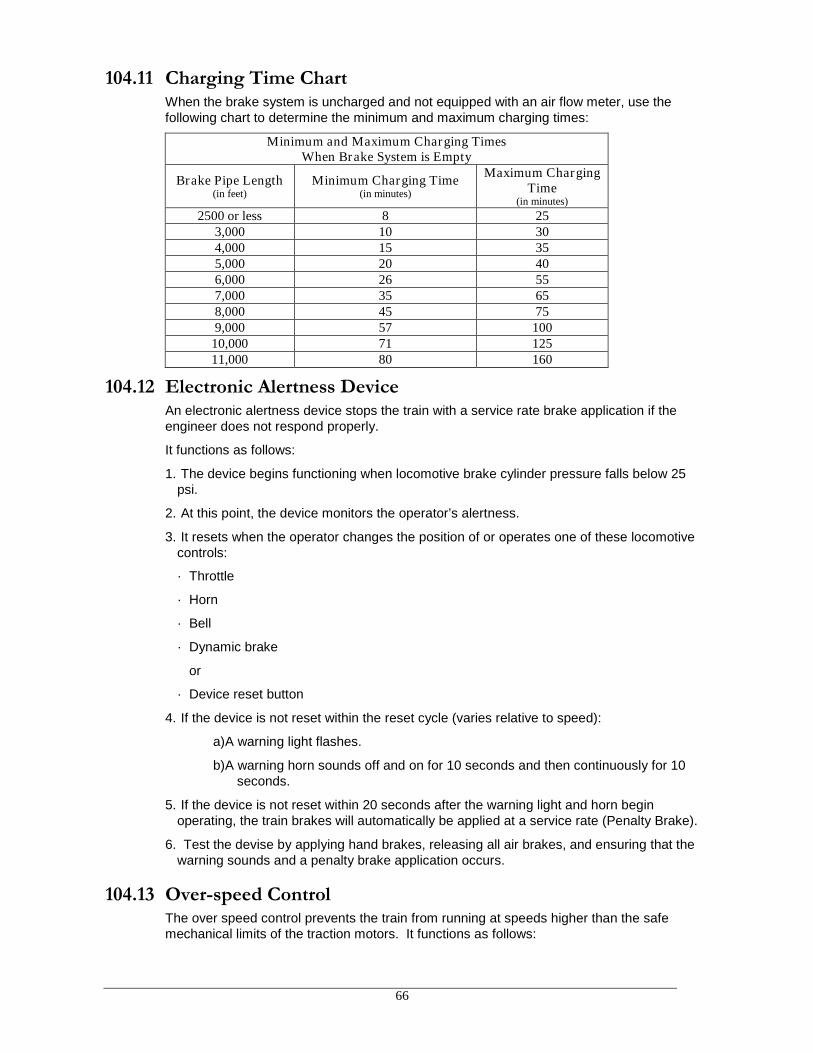
66
104.11 Charging Time ChartWhen the brake system is uncharged and not equipped with an air flow meter, use thefollowing chart to determine the minimum and maximum charging times:
Minimum and Maximum Charging TimesWhen Brake System is Empty
Brake Pipe Length(in feet)
Minimum Charging Time(in minutes)
Maximum ChargingTime
(in minutes)
2500 or less 8 253,000 10 304,000 15 355,000 20 406,000 26 557,000 35 658,000 45 759,000 57 100
10,000 71 12511,000 80 160
104.12 Electronic Alertness DeviceAn electronic alertness device stops the train with a service rate brake application if theengineer does not respond properly.
It functions as follows:
1. The device begins functioning when locomotive brake cylinder pressure falls below 25psi.
2. At this point, the device monitors the operator’s alertness.
3. It resets when the operator changes the position of or operates one of these locomotivecontrols:
· Throttle
· Horn
· Bell
· Dynamic brake
or
· Device reset button
4. If the device is not reset within the reset cycle (varies relative to speed):
a)A warning light flashes.
b)A warning horn sounds off and on for 10 seconds and then continuously for 10seconds.
5. If the device is not reset within 20 seconds after the warning light and horn beginoperating, the train brakes will automatically be applied at a service rate (Penalty Brake).
6. Test the devise by applying hand brakes, releasing all air brakes, and ensuring that thewarning sounds and a penalty brake application occurs.
104.13 Over-speed ControlThe over speed control prevents the train from running at speeds higher than the safemechanical limits of the traction motors. It functions as follows:

67
· If train speed increases to an unsafe level, the safety control device sounds a warning.
· If the train does not slow within 6 to 12 seconds of the first warning sound, the over-speed control device applies the train brakes and trips the PC switch.
Slow Train
To slow the train when the safety control device sounds a warning, comply with thefollowing:
1. On locomotives with 26L, 30CDW, and CCB brake equipment, move the automaticbrake handle to SUPPRESSION within the 6- to 12-second warning period.
2. On locomotives with other brake equipment, reduce the brake pipe pressure 6 to 8 psi,or more if necessary.
Recover
To recover when the over-speed control applies the train brakes:
1. On locomotives with 26L, brake equipment, move the automatic brake handle toSUPPRESSION.
2. On locomotives with other brake equipment, move the automatic brake handle to LAP.
3. Move the throttle to IDLE and wait 60 seconds.
4. After the train stops, move the automatic brake handle to RELEASE and note that:
· Brake pipe pressure is restored.
· PC light goes out.
· Brakes release.
Note: Some locomotive equipment has been modified to slow the train during thewarning period with the automatic brake valve in MINIMUM REDUCTION. Unless theengineer knows that the locomotive being operated includes this modification, theSUPPRESSION position should be used.
104.14 Reserved
104.15 Defect DetectorsIn Canada, trains may not be operated in excess of 60 miles, or move past 2 consecutivenon-operational hot box detectors without having been inspected on each side of the entiretrain. These inspections must be performed by:
(i) hot box detectors; or(ii) pull-by inspection by crew members of the train; or(iii) passing train inspection by:
• wayside employees, or• crew members of other trains.
Passing train inspections must be conducted by 2 employees on opposite sides ofthe train when practicable.

68
104.15.1 Defect Detector Message and Required Action
DETECTORMESSAGE
TRAIN CREW ACTIONADDITIONAL
INSTRUCTIONSNo Defects Proceed NONE
Detector malfunction, orno message is heard
Contact RTCReport detector
malfunction to the RTCA warning tone (a defect
has been detected)Reduce Speed to LESS
THAN 20 MPH.NONE
“…First Hot Box WestRail, XXX From Head of
Train.”
STOP THE TRAIN
Inspect car involved and 20axles ahead and 20 axles
behind
Notify the RTC
Detector AlarmMessage may identifymore than one defect.
Inspect train for allreported defects
Defect detector radio readouts count axles from the head end to the rear of train. Crewsmust carry a 200 degree temperature testing stick while on duty. On roller bearing cars, todetermine when the bearing is overheated and the car must be set out, be governed by thefollowing:
The temperature of suspect roller bearings must be tested using a temperature testing stickby making a mark approximately 3 inches long on the outside of the bearing (not the bearingcap). If the mark melts, the car must be set out.
When inspections are required, employees must inspect for other car defects, such assticking brakes, hot journal bearings and broken or extensively cracked wheels. If the defectis sticking brakes, be sure the hand brake is in full release and the retainer valve is in directrelease. It may be necessary to cut out air brakes on a suspected car. If the defect is acracked or broken wheel, brake rigging dragging or wheel with bad flat spots, precautionmust be taken to remove car or locomotive from train. It may be necessary to leave the caror locomotive standing until assistance can be received. The RTC must be notified of thecondition.
A train that passes 2 detectors in sequence giving malfunction messages must be stoppedand an inspection performed for possible defects.
When a car is reported twice by a defect detector, and no defect is found, the car must beset out at the first available point, not exceeding 25 MPH from the second inspection site tothe set out site.
When a train sets a car out for any reason, the car should be placed at a location that willbest allow the mechanical department access to effect repairs. The car should be tagged inthe area of the defect, and the RTC or mechanical department notified of the car number,location, and a description of the problem.
Crew members operating Key Trains are reminded to consult US Hazardous MaterialsInstructions and/or Canadian Dangerous Goods Instructions for Rail when Hot BearingAlarms are received.

69
104.15.2 Special Dangerous Commodities
Timetable Special Instructions indicate mandatory inspection points for trains carryingspecial dangerous commodities.
Defect detectors which report a normal inspection are sufficient to allow the movement toproceed.
If a train carrying SPECIAL dangerous commodities passes a defect detector identified inSpecial Instructions and any one of the following conditions is reported:
• the defect detector is withdrawn from service,• the defect detector reports a malfunction or is otherwise known to be inoperative,
• any part of the movement passes the HBD at 8 MPH or less,
• no message is received or heard
Stop the train within one mile and perform a pull by (not exceeding 5 MPH) or walkinginspection of both sides of the train up to and including 8 axles behind the last SpecialDangerous Commodity car.

70
106.0 Fuel Conservation
To accomplish maximum fuel efficiency, use the most efficient method consistent with goodtrain handling. Unless other local isolate/shut down instructions apply, locomotives of thefollowing type must be the first locomotives isolated or shut down when meeting maximumhorsepower guidelines: B-23, SD-40, GP-20.
Managers may issue instructions to shut down or isolate units based on local operatingplans. Crews will comply with the instructions regardless of current or forecastedtemperatures.
106.1 Regulating HorsepowerTrain and engine crews are required to isolate or shut down units in a consist that are inexcess of the horsepower needed to maintain track speed.
106.2 Isolating or Shutting Down Locomotives En RouteWhen isolating or shutting down a locomotive en route for fuel conservation purposes, thefollowing will apply:
1. Temperature 36 degrees F or above - locomotive must be shut down; do not drain. (Thisincludes locomotives equipped with automatic start/stop systems)
2. Temperature below 36 degrees F - locomotive must be isolated; do not shut down.
Exceptions:
· Locomotives not equipped with freeze protection equipment - must not be isolated iftemperature is below 32 degrees F.
· GP-20 locomotives are equipped with antifreeze coolant and may be shut down whentemperature is above 0 degrees F.
106.3 Shut Down Requirement for Locomotives Not Being UtilizedAt ALL points when locomotive(s) will not be utilized for fifteen minutes or more, or whenunattended, all locomotives except locomotive maintaining a train’s air brake pipesystem must be shut down when current and expected ambient temperature is 36degrees F or above. When in doubt as to the temperature or the length of timelocomotive(s) will not be used, contact the RTC or local supervisor.
Exception: Automatic Engine Start/Stop Systems - Locomotives equipped withautomatic engine start/stop systems are identified by labels and instructions affixedinside the locomotive cab and at the engine start/stop station. The AESS system, on asingle locomotive, within a locomotive consist, may be utilized to maintain a train’s airbrake system as outlined above since they are designed to automatically shut down andrestart as conditions require. These conditions include maintaining necessary mainreservoir and brake pipe pressures. All locomotives not equipped with AESS within theconsist must be shut down manually.
A green “Enabled” light is positioned on the engineers control stand on some automaticstart/stop systems referred to as “Smart Start”. Small warning horns or bells sound insidethe cab and outside the locomotive before an automatic shut down or restart occurs. Autostart/stop equipped locomotives will automatically shut down when conditions permit.

71
106.3.1 Shut Down Requirements for Locomotives Equipped withAuxiliary Power Units (APUs)
1. APUs must remain in stand by or enabled modes at all times and in all weatherconditions. APUs are enabled when the red APU emergency stop button ispulled out.
2. When a locomotive is to be shut down follow posted instructions for APUoperation. Do not use the engine stop button/emergency fuel cut-off switch.
3. Shut down APU locomotives regardless of ambient temperature.
4. Do not open the main battery switch following main engine shutdown.
5. Report defective APUs to the mechanical department.
106.4 Shut Down ProceduresShut down locomotives left standing as follows:
1. Isolate the engine.
2. Depress the engine stop button.
3. Turn off all switches and circuit breakers on the control stand and engine control panelto conserve battery life.
Exception: The following switches must be left on or closed:
a. Auto water drain on all engines equipped.
b. Auxiliary turbo lube oil pump circuit breaker on EMD turbocharged engines.
c. Computer-control circuit breaker if equipped.
d. Open battery knife switch on the following locomotives:
· All GE locomotives
· EMD-GP50, GP60, SD60, SD70, and SD75
When locomotives are shut down in consist, such as light engines and excess power in atrain, the following switches and circuits must be on or closed, in addition to those above:
1. Battery knife switch
2. Control circuit breaker
3. Local control circuit breaker
106.5 Locomotive StartingThe following are basic instructions for all locomotives:
1. Close battery knife switch.
2. Turn on Engine Run, Control and Fuel Pump Switches on control stand.
3. Turn on all necessary switches and circuit breakers on engine control panel.
Note: On EMD locomotives, all circuit breakers in black area must be on for engine tostart.
4. On locomotives that have been shut down 4 hours or more, open flash (test) cocks androtate engine at least three revolutions. If water is detected in any cylinder, contactmechanical department and do not make any further attempts to start the locomotive.
5. Close test cocks and start locomotive. If locomotive(s) fail to start, contact theMechanical Department for assistance.

72
Note: Computer-equipped GE locomotives experience a 5-10-second delay after thestart switch has been placed to start before the diesel engine begins to turn over.
6. Train and engine crews must not attempt to jump start locomotives, unless under thedirection of the Mechanical Department.
106.6 Cold Weather Protection for Locomotives Not Equipped withAESS or APUsWhen temperature is below or expected to drop below 0 degrees F, the followingprecautions must be followed to prevent locomotive freezing.
A. Locomotives Set Out for Service and/or Left Unattended
1. Secure locomotive.
2. Place engine control switch in Run 3-No Load. (Turn generator field circuit breaker offor pull generator field fuse.)
3. Notify RTC, advising location set out, fuel readings and method used to prevent freezedamage.
B. Locomotives Set Out Due to Defects
1. Secure locomotive per existing instructions.
2. Place engine control switch in Run 3-No Load, if not equipped with winter isolate. (Turngenerator field circuit breaker off or pull generator field fuse.)
3. Notify RTC, advising location set out, fuel readings and method used to prevent freezedamage.
4. If locomotive cannot be placed in Run 3-No Load or defect requires for locomotive to beshut down, drain the cooling water system.
5. In all cases, when defect occurs, contact the Mechanical Department.
Note: Do not set out locomotive(s) for defect(s) unless a safety issue exists or underdirection of the Mechanical Department.
C. Locomotives Developing En route Failures
Drain locomotive cooling system when any of the following conditions exist:
1. Locomotive has shut down and cannot be restarted.
2. Locomotive has defect(s) that prevent loading or throttle speeds from developing.
3. If locomotive cannot be placed in Wi Run 3-No Load.
Note: Care should be taken to spot the locomotive so that if the cooling water systemmust be drained it will not go into a waterway or public roadway. In addition, contactMechanical Department and advise of action taken and if the cooling water systemhas been drained or if it drained automatically, advise if a waterway was impacted.
D. Locomotive Fuel Level Reporting
During cold weather, when trains are left between terminals, crew must contact RTC,advising fuel readings of all locomotives in consist.
Note: Fuel gauges on both sides of locomotives must be compared.

73
106.7 Speed Reduction for Fuel ConservationThe RTC may issue instructions for train speed to be reduced to less than maximumauthorized timetable speed for fuel conservation. To take advantage of descending gradesituations, this restriction only applies when your train is in power (for these instructions,power is defined as throttle positions 3 through 8).
When operating at locations where power is not required, train may be operated atmaximum authorized timetable speed for that location.
106.8 Movement of Light Engines and Caboose Only MovesTo conserve fuel, isolate excess units in a consist to handle movement as follows:
1. Only one axle of power per each 120 tons of consist may be on line.
2. When operating on sustained grades exceeding 2.0 percent, only one axle of power pereach 90 tons of consist may be on line.
3. Do not isolate excess units if doing so will drop the locomotive consist below anyminimum dynamic brake requirements listed in railroad special instructions.
Note: This rule is intended to limit excess tractive effort only. Employees are encouragedto use the “Dynamic Brake Only” feature on locomotives so equipped when complying withthis rule.

74
GlossaryAccelerometerAn indicator that displays in MPH per minute the rate of increase/decrease of speed.
ActuatingUsing of feature of the independent brake valve to charge the actuating pipe from the main reservoirand prevent or release a locomotive brake application from a brake pipe reduction.
Air BrakeA system of compressed air devices, controlled manually, electronically or pneumatically, that makethe car or locomotive slow down or stop.
Air Brake EquipmentThe equipment that supplies and exhausts air to and from the brake cylinders, but does not includefoundation brake gear and hand brakes.
Air Brake HoseA reinforced tubing. On each car or engine, the tubing is attached to a nipple that screws into theangle cock at the end of the brake pipe. The other end of the hose includes a coupling (glad hand)that fits into an identical coupling on the adjoining car. The complete arrangement connects airbetween the brake pipes of the cars and the locomotives throughout the train.
Air Brake SystemAll of the devices for operating air brakes to control the speed of and stop a locomotive or train. Thesystem includes the operating devices, pipes, hoses, fittings, and foundation brake gear.
Air CompressorA locomotive device, powered by the diesel engine or an electric motor, that compresses air foroperating the air brakes and all other air-operated devices on locomotives and cars.
Air Compressor Control SwitchA device that controls the loading and unloading of the compressor at the proper main reservoirpressures.
Air Flow Indicator (AFI)An instrument that indicates the volume of the air flowing through the automatic brake valve into thebrake pipe.
Air GaugeAn instrument that indicates air pressure in pounds per square inch (psi).
Alignment Control CouplerSpecially equipped couplers, installed on most locomotives that only allow the coupler in buff tomove laterally within certain limits. This equipment minimizes rail turnover, wheel climb andjackknifing.
Ampere (Amperage, Amps)The standard unit for measuring electric current.
Angle CockA manually operated device located at each end of the brake pipe on locomotives and cars to permitor prevent air flow.
Articulated Multi-platform CarA car with multiple units (segments) that have articulated couplings and which the units share acommon truck.
Automatic Brake ValveA manually operated electronic controller or pneumatic valve on the locomotive that controls the train

75
and engine brakes.
Auxiliary ReservoirA storage volume, charged from the brake pipe, to receive and store air to apply brakes on a car orlocomotive. In freight car equipment, the auxiliary reservoir and emergency reservoir are combined inone structure.
“B” End (of car)The end where the hand brake is located unless otherwise identified.
Back-up Valve or HoseA device, either portable or permanently connected to the brake pipe, that controls brakes from thecar that it is attached to. The device can apply the brakes with a service or emergency application.
Balanced BrakingControlling train speed by making enough of a brake pipe reduction to stabilize speed on a grade,then allowing the automatic brake valve pressure maintaining feature to hold the brake applicationconstant regardless of brake pipe leakage. This ordinarily is accomplished in combination withdynamic braking.
Bleed (Bleed-off)Venting air pressure to the atmosphere, such as venting air pressure from the brake cylinder ofindividual cars, by using the release valve.
Brake ApplicationA brake pipe pressure reduction (no matter how made) that causes the control or distributing valve tomove to the service or emergency position.
Brake CylinderA metallic cylinder containing a piston. Compressed air forces the piston outward to apply thebrakes. When the air pressure is released, the piston returns to its normal position by a releasespring coiled around the piston rod inside the cylinder.
Brake PipeThe section of air brake piping of a car or locomotive that supplies the reservoirs. It also connects thepiping to allow the locomotive engineer to control the car brakes. The pipe is 1-1/4 inches in diameterand extends from one end of the car to the other. At the ends, flexible hoses connect the cars. Whena train is made up and all brake pipes on the cars are joined together, the entire pipe line is calledthe brake pipe.
Brake Pipe GradientThe difference in brake pipe pressure between the locomotive (or source of supply) and the rear carof the train. Brake pipe gradients may be:
· Normal Gradient. The gradient that exists when the system is fully charged.
or
· False Gradient. The temporary gradient that exists when the system is less than fully charged (forexample, the exaggerated difference between the head end and rear end after a release).
or
· Inverse Gradient. The temporary condition when the brake pipe pressure is higher at the rear ofthe train than at the head end of the train (for example, during a service brake application).
Brake Pipe PressureThe amount of pressure in pounds per square inch (psi) in the brake pipe (commonly expressed inpounds).
Brake Valve Cutoff ValveA device on locomotives that can cut out the charging and service functions of the automatic brake

76
valve. This valve also properly positions the brake valve for passenger or freight operation.
Branch Pipe Cutout CockA device on locomotives and cars that isolates the control valve from the brake pipe.
Control ValveA device on locomotives or cars that charges the reservoirs and applies or releases brake cylinderpressure when brake pipe pressure reduces or increases.
DC LocomotiveDC locomotives are equipped with DC traction motors and are affected by maximum continuouscurrent ratings or short time operating ratings.
Dead Engine FeatureA device near the locomotive control valve that is used when the unit is handled dead-in-train. Whenthe dead engine cutout cock is opened, the main reservoirs are charged from the brake pipe tooperate the engine brakes.
Disturbed TrackA section of passable track that has a temporary speed restriction imposed because various defectsor track maintenance has affected the integrity of the track.
Draft GearThe connection between the coupler rigging and the center sill. This connection receives andcushions the shocks associated with in-train forces or coupling.
Drawbar Forces (In-train Forces)Forces at the couplers between cars and/or locomotives that may be either draft (stretched) or buff(compressed), depending on train operation.
Dynamic BrakeAn electrical device that converts some of the energy developed by a moving locomotive into aneffective retarding force.
· Dynamic Brake Holding Feature
A feature of the lead, controlling locomotive that allows dynamic braking effort when a PCS opencondition exists.
·Dynamic Brake Interlock (DBI)
A device that will automatically keep the locomotive brakes from applying when automatic brakes areapplied during dynamic braking.
· High Capacity Dynamic Brakes – provide approximately 13,500 lbs. of effort per axle instead of10,000 lbs. per axle as other dynamic brake systems.
· Flat (Grid Control) Dynamic Brake System – a dynamic brake system that provides retardationthat is controlled solely by the position of the dynamic brake lever. Maximum retardation occurs atPosition 8.
· Taper (Speed Control) Dynamic Brakes – a dynamic brake system that provides retardationrelative to both speed and dynamic brake handle position. The higher the speed, the greater theretarding force developed for a given handle position. At higher speeds, full dynamic brake effort isreached at Position 4.
Electronic Alertness ControlA safety control system that senses the activity of the engineer. As the engineer goes about normalactivities, any such changes will reset the control and start a timing circuit. If, during the timingperiod, no additional activity is detected, an audible and/or visual alarm occurs. If activity still doesn’toccur for another period, approximately 6 seconds, a penalty brake application is initiated.

77
Emergency ApplicationA rapid reduction of brake pipe pressure that causes the control valves to move to the emergencyposition and the vent valves to open. This equalizes auxiliary reservoir, emergency reservoir, andbrake cylinder pressures.
Emergency Brake ValveA manually operated device on equipment that initiates an emergency brake application.
Emergency ReservoirA storage volume, charged from the brake pipe, to receive and store air used during emergencybrake applications and certain recharge features.
Empty Bulk Commodity Unit TrainA train made up entirely of empty cars used to transport coal, grain, ore, potash, molten sulfur, sodaash, phosphate rock, oil, taconite or other bulk commodities.
End of Train Telemetry System (Telemetry Components)End-of-train telemetry devices is a radio end-of-train telemetry system that consists of:
· End-of-train device (ETD) mounted on the trailing coupler of the last car.
· Head-of-train device (HTD) mounted in the locomotive.
An ETD that has not been armed to, provides:
· Last car brake pipe pressure monitoring.
· Last car motion status (moving or stopped).
· Marker light status (on or off).
· ETD battery status.
An ETD that has been armed to (emergency enabled), provides capability to initiate an emergencybrake application at the rear of the train. Both the HTD and ETD must be equipped for two-waycommunication and the HTD must be armed to the ETD (emergency enabled). An Emergencytoggle switch associated with the HTD cab display is used to activate the ETD emergency valve.
A system of components that determines the rear car brake pipe pressure and transmits thatinformation to the display on the controlling unit.
A 2-way ETD transmits and receives information between the head-end and rear-end units. Theadditional purpose of a 2-way ETD is to provide a way to initiate from the locomotive an emergencybrake application at the rear of the train. For this to happen, both the head-end and the rear-endunits must be equipped for two-way communication and armed (emergency enabled). An Emergencytoggle switch associated with the ETD cab display is used to activate the ETD emergency valvelocated on the rear- end unit.
Equalizing ReservoirA small reservoir connected to a piston or diaphragm chamber and used in automatic air brakeoperations. It is only cut in on the controlling unit. The reservoir’s purpose is to add a volume of air toone side of the chamber, which can be accurately controlled.
When a brake pipe reduction occurs, air is drawn from the equalizing reservoir. The reservoir thenautomatically draws the proper amount of air from the brake pipe. For this reason, the brake pipepressure and the equalizing reservoir pressure are always the same, except when they areequalizing after a brake pipe reduction or a brake pipe charging operation.
Foundation Brake GearThe levers, rods, brake beams, etc. that connect the brake cylinder piston rod to the brake shoes sothat when air pressure forces the piston out, the brake shoes are forced against the wheels.
Full Service ApplicationA brake pipe reduction made only to the point at which the auxiliary reservoir and brake cylinder

78
pressures equalize. Any further reduction in the brake pipe pressure, except an emergencyapplication, will not affect the amount of pressure in the brake cylinder. Therefore, air is being wastedfrom the brake pipe (over reduction).
The chart below shows the reduction needed for a full-service application for various initial brakepipe pressures. Also listed is the brake cylinder pressure at full service for various initial brake pipepressures:
Initial Brake Pipe Pressure Service Equalization Pressure Brake Pipe Reduction to ObtainEqualization
90 psi 64 psi 26 psi
105 psi 75 psi 30 psi
110 psi 78 psi 32 psi
Grade (of Track)Grade is other than level track and is usually expressed as a percentage. The percentage is thenumber of feet the track rises or falls in a distance of 100 feet. For example, a 1-percent ascendinggrade means that the track rises 1 foot in elevation for every 100 feet the equipment travels on thetrack. Unsecured rail equipment may roll on a grade.
Grade designations include the following:
· Light Grade: Less than 1.0 percent.
· Heavy Grade: At least 1.0 percent for a distance of 3 miles or more.
· Mountain Grade: 2.0 percent or greater for a distance of 2 miles or more.
Hand BrakeA mechanical arrangement of levers, chains, rods, gears, and fulcrum. When applied manually bywheel or lever, the hand brake forces the brake shoes against the braking surfaces (wheel tread ordisc) to control car or locomotive movement.
Head of Train Device (HTD)A radio device located in the locomotive cab that communicates with an End of Train Device (ETD).The HTD displays:
· Last car brake pipe pressure.
· Last car motion status (moving or stopped).
· Marker light status (on or off).
· ETD battery status.
· Communication Status with ETD
· 2-Way Armed Status
· Distance measurement referenced to locomotive movement.
And provides:
· Audible alarms pertaining to status changes
· Arming capability to a selected 2-way ETD.
· Interface for Manual and Automatic initiated ETD emergencies
HelperDistributed power or manned helper added to a train to assist movement.
Horsepower Per Trailing Ton (HPT)The total horsepower of all working locomotives divided by the total trailing weight of the train in tons.For example, a train powered by 15,000 horsepower and having a trailing weight of 4,285 tons has a

79
3.5 horsepower per trailing ton ratio (15,000 HP divided by 4,285 tons).
Independent Brake ValveA brake valve that controls the locomotive brakes independent of the automatic brake valve handleposition.
Independent Pressure Switch (IPS)A device on a locomotive that cancels the extended range portion of dynamic braking or all dynamicbraking when a sufficient independent brake application occurs. This switch prevents the locomotivewheels from sliding because of excessive braking.
InterchangeA location where railroads exchange rolling equipment.
Intermodal EquipmentEquipment designed to carry trailers, containers, automobiles.
Intermodal TrainsTrains made up of entirely of intermodal equipment.
Isolation SwitchA switch on diesel electric locomotives that has two or three positions. In the RUN position, the unitis “on the line,” responds to control, and develops power. In the ISOLATION (or Stop-Start) position,the unit is isolated from the consist and does not develop power or respond to control.
LinkingThe process of electronically connecting the controlling lead unit to the controlling distributed powerunit on a distributed power train.
Light LocomotiveOne or more units, with or without a caboose, not coupled to cars.
Loaded Bulk Commodity Unit TrainA train made up entirely of loads of coal, grain, ore, potash, molten sulfur, soda ash, phosphate rock,oil, taconite or other bulk commodities.
Main ReservoirAn air reservoir on the locomotive for storing and cooling compressed air.
Minimum Continuous SpeedMinimum continuous speed is the slowest speed at which a DC locomotive can operate continuouslyin Throttle 8. Locomotive traction motors operating under these conditions develop the highestamperage possible before overheating. The minimum continuous speed varies and is indicated bythe rating plate on the locomotive.
Minimum ReductionThe first position of the automatic brake valve that initiates a service application of 6 to 8 psi.
Manned HelperA helper controlled by an engineer in the controlling unit of the locomotive helper consist.
MU Cutout Cock (MU-2-A, Dual-Ported Cutout Cock)A device for cutting in or out the independent brake valve.
Non-articulated Multi-platform CarsA car with multiple units (segments) that are connected with solid drawbars. Each unit is a stand-alone unit and does not share a common truck with another unit.
Off AirNot connected to a continuous source of compressed air.

80
OverchargeBrake equipment charged to a higher pressure than the regulating valve is adjusted for or canmaintain. In such a condition, brakes on a portion of the train may not release.
Penalty Brake ApplicationAn automatic full service brake application caused by various safety devices.
Pneumatic Control Switch (PCS)An air-operated switch, activated by an emergency or penalty brake application, that drops theengine speed to idle on EMD locomotives or throttle notch 1 on GE locomotives.
Pressure Maintaining BrakingControlling train speed by making enough of a brake pipe reduction to stabilize speed on a grade,then allowing the automatic brake valve pressure maintaining feature to hold the brake applicationconstant regardless of brake pipe leakage.
Pressure Maintaining FeatureA system designed to overcome brake pipe leakage both in the RELEASE and SERVICE positionsof the automatic brake valve. This allows a constant brake application to be held as long as needed.
Reduction (of the brake pipe)A decrease in brake pipe pressure at a rate and of an amount sufficient to cause a train brakeapplication to be initiated or increased.
Reduction Relay ValveA device on long cars that helps brake pipe pressure reduce during service and emergency brakeapplications. The valve compensates for the added length of brake pipe on long cars.
Regulating ValveThe valve that reduces air pressure from the locomotive’s main reservoir to the desired pressure inthe brake pipe. The regulating valve will automatically maintain that pressure when the automaticbrake valve is in the RELEASE position.
Retaining ValveA manually operated valve used on cars to exhaust brake cylinder pressure completely or tomaintain a predetermined pressure.
Safety Inspection location - a location designated by the Company, and recorded with TransportCanada, where persons are employed for the purpose of performing safety inspections on carsand/or locomotives.
Service ApplicationWhen brake pipe pressure exhausts at a service rate to apply the train brakes.
Slack ActionMovement of part of a coupled train at a different speed than another part of the same train.
Solid Block (of cars)Two or more freight cars coupled together and added to, or removed from a train as a single unit.
Thermal Cracks (in wheels)Cracks in a railroad wheel, normally caused by heat generated on the tread and flange of the wheelfrom excessive braking.
Throttle ModulationThe action of adjusting the throttle one notch at a time between idle and position 8 to control trainspeed without the application of air brakes.
Tons per Dynamic Brake AxleThe total gross trailing tonnage of the train divided by the number of axles of locomotives, including

81
helper locomotives, operating in dynamic brake. (Refer to locomotive data tables in system specialinstructions for dynamic brake axle ratings.
When making this calculation, include in the gross trailing tonnage the weight of any locomotive,including a helper locomotive, not operating in dynamic brake or with dynamic brake cut out.
Tons per Operative BrakeThe gross trailing tonnage of the train divided by the total number of cars having operative brakes.For example, a 100-car train with all brakes operating, having a total train weight of 6,000 tons, has60 tons per operative brake (6,000 tons divided by 100 cars).
Train lists showing average tons per car or platform will equal tons per operative brake when:
· The train list is current (no additional pickups or setouts have been made).
· No brakes have been cut out.
· There is one brake per car or platform (Note: This is not the condition for some equipment, such asarticulated intermodal cars).
Transfer Train MovementA train that travels between a point of origin and a point of final destination not exceeding 20 miles.Such trains may pick up or deliver freight equipment while en route to destination.
UnattendedMeans cars and/or locomotives left standing and unmanned in such a manner that the brake systemof the cars and/or locomotives cannot be readily controlled.
Vent ValveA valve attached to the brake system of a car or locomotive. The valve responds to an emergencybrake pipe pressure rate of reduction by venting the brake pipe at each vehicle to the atmosphere.As a result, the emergency application spreads throughout the train.
Wheel SlidingWhen the wheel rotates slower than lengthwise movement dictates.
Wheel SlippingWhen the wheel rotates faster than lengthwise movement dictates.
Yard Test PlantA system of piping and fittings that supplies air at convenient locations to charge and to test carswithout a locomotive.