bus air brake system training - apta.com · •green supply and primary brake system •red...
TRANSCRIPT
APTA Standards Quarterly Webinar Series
Bus Air Brake System Training
Presented by
APTA Brake and Chassis Working Group

Deputy Chief Engineering Officer Southeastern Pennsylvania Transportation Authority (SEPTA)Philadelphia, PA
Jerry Guaracino
Moderator

Brian D. MarkeyPresidentCustom Training Aids Inc.La Verne, CA
PRESENTER

Frank FordeEquipment Maintenance InstructorLos Angeles Metropolitan Transportation Authority Los Angeles, CA
John BrundageTransit & Rail Vehicle TechnicianCH2MBoston, MA
PANELISTS

Related APTA Standards
• APTA BTS-BC-RP-005-10, Rev. 1:Troubleshooting Common Transit Bus S-cam and Air Brake Complaints
• APTA BTS-BC-RP-006-17: Transit Bus Air Disc Brake Operation and Wheels On Inspection
• APTA BTS-BC-RP-007-17: Transit Buss Air Disc Brake Wheel Off Inspection and Reline
For additional resources visit: http://www.apta.com/resources/standards/bus/Pages/default.aspx

Objective
Welcome to today’s webinar in which you will learn how the air brake system works. We will cover and
discuss the three sub-systems of the air brake system operation, inspection points, visual and functional
checks.

• The information on this webinar is to be used in conjunction with the original equipment manufacturer (OEM) and air brake parts manufacturer service manuals.
• Proper tools and safety equipment must always be used when working on brake systems.

Air Brake System Training

Air brake system is comprised of three sub-systems.
•Air Supply System
•Air Control System
•Foundation Brake System
System Layout

•Supply system provides, conditions, and stores the compressed air which is the medium of control and power of the vehicle’s braking system
Air Supply System

•Control system regulates the pressure and flow of compressed air from the supply system
Air Control System

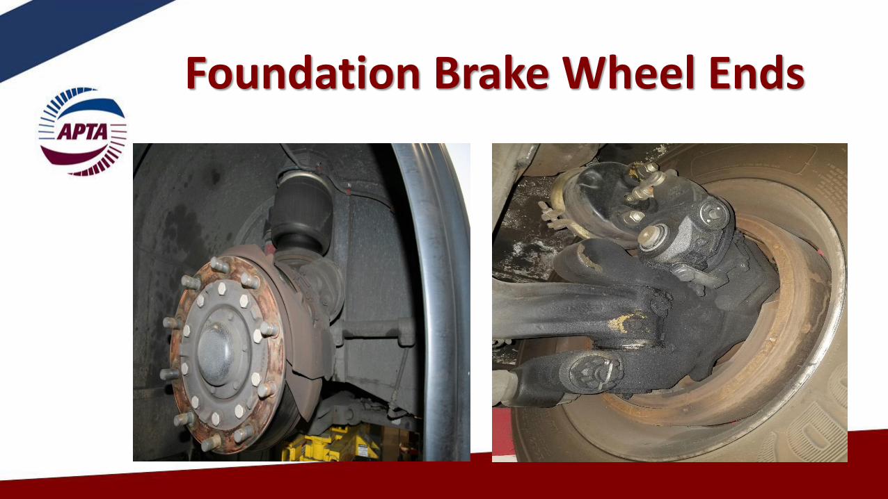
•Wheel end components make up the foundation brake. The foundation brake is the friction brake, related parts and components that convert motion to heat energy and stop the bus
•The air system controls the foundation brake
Foundation Brake

Foundation Brake Wheel Ends

•Air Leaks are the root cause for the majority of air system problems
•The condition of the supply system will indicate the health of the complete air system
•A dirty supply system will result in a problematic control and foundation system
Shop Tips

•Maximum allowable static air loss is 2 PSI in one minute•Static air loss is with service brakes released
and parking brake fully applied•Maximum allowable applied air loss is 3 PSI in
one minute•Applied air loss is with service brakes fully
applied and parking brake released
Air Loss

•Air leaks at connections and valve exhaust ports are acceptable if air loss does not exceed allowable limits•Air leaks at brake chambers are a violation of
CVSA and meet/result in Out of Service Criteria •With the service brakes fully applied, 90% of
the air pressure in the brake reservoir must be available at the brake chamber•32 oz is the maximum allowable limit for liquids
in each reservoir
System Operation
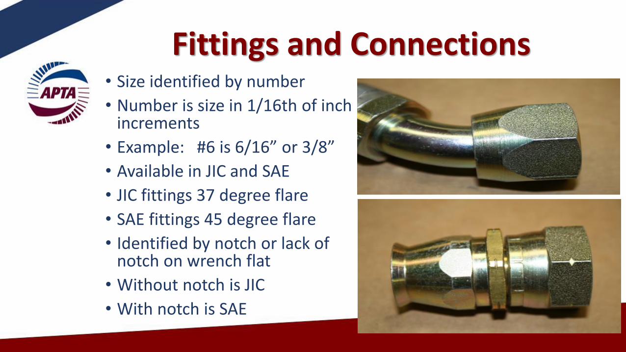
• Size identified by number
• Number is size in 1/16th of inch increments
• Example: #6 is 6/16” or 3/8”
• Available in JIC and SAE
• JIC fittings 37 degree flare
• SAE fittings 45 degree flare
• Identified by notch or lack of notch on wrench flat
• Without notch is JIC
• With notch is SAE
Fittings and Connections

COMPRESSION D.O.T FITTING BRASS PUSH-TO-CONNECT D.O.T. FITTINGS
Air Brake Fittings

COPPER TUBE COMPRESSION FITTING
COMPRESSION D.O.T FITTING
Compression Fitting Comparison

Air Brake Fitting Specifications
Air brake fitting must meet the following specifications
•All air brake fitting are required to be DOT approved / certified
•All air brake fitting designed for air brake plastic tubing will have DOT stamped or engraved on the fitting
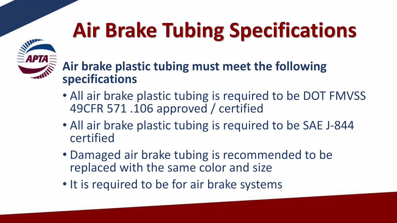
Air Brake Tubing Specifications
Air brake plastic tubing must meet the following specifications
• All air brake plastic tubing is required to be DOT FMVSS 49CFR 571 .106 approved / certified
• All air brake plastic tubing is required to be SAE J-844 certified
• Damaged air brake tubing is recommended to be replaced with the same color and size
• It is required to be for air brake systems

Air Brake Tubing SAE J-844 Type 3B 3/8 OD DOT
Air Brake Tubing SAE J-844 Type 3B 1/2 OD DOT
Air Brake Tubing Specifications

Plastic Fuel Line Tubing Air Brake Tubing SAE J-844 TYPE B 1/2 OD
DOT
Air Brake Tubing Specifications

•Green Supply and primary brake system
•Red Secondary brake system
•Brown Parking, Emergency, Spring Brakes
Governor control circuit
•Black Accessory system, suspension system
•Blue Suspension system some buses
Air Tubing and Line Colors

Typical Air System Schematic

•The air supply sub-system is basic to all vehicles
•The control system can vary from vehicle to vehicle
Supply System

Supply System Components• Air compressor• Air Governor• Air Dryer• Reservoirs• Single Check Valves• Low Pressure Warning System• Safety Valve• Drain Valve• Pressure Protection Valve• Regulator Valve

Air Brake System Training
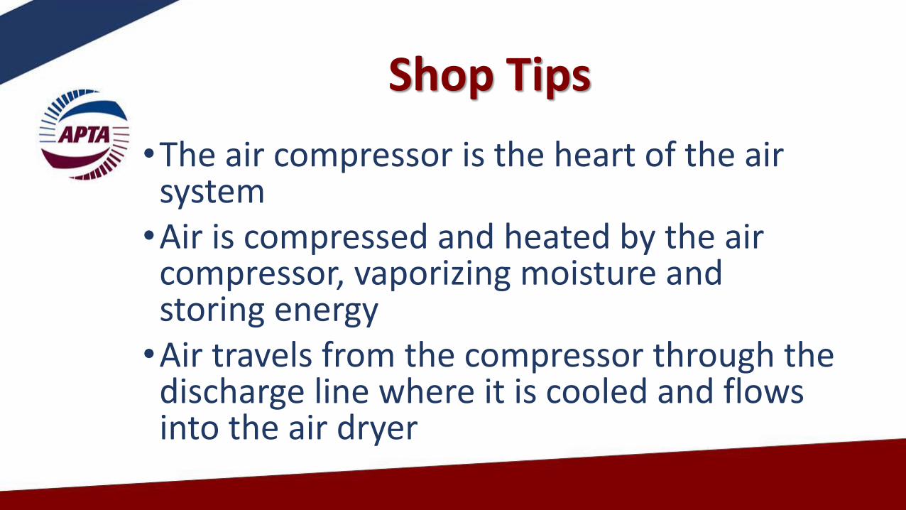
•The air compressor is the heart of the air system•Air is compressed and heated by the air compressor, vaporizing moisture and storing energy•Air travels from the compressor through the discharge line where it is cooled and flows into the air dryer
Shop Tips

•The air dryer removes contaminants such as moisture, oil, and carbon •Air then flows into the supply reservoir commonly called the wet tank•Air flows from the supply reservoir to all system reservoirs•Air governor measures supply reservoir air pressure and controls the air compressor
System Operation

•Supply reservoir pressure is protected by a safety valve
•A drain valve is required on all air reservoirs
•Air reservoirs should be drained frequently to prevent contaminants from flowing through the system
System Operation

•Air flows from the supply reservoir to the primary, secondary, and accessory reservoirs•Primary and secondary brake reservoirs are protected by a single check valve allowing air to flow only into these reservoirs and not back to the supply reservoir if the supply reservoir develops a leak
System Operation

System Operation
•Once air flows through a single check valve it is no longer supply system pressure. It becomes system supply pressure
• It can only be used to operate that system

System Operation
•Primary and secondary air system reservoir pressure is monitored by the dash air pressure gauge and low pressure warning device.•Low pressure switches are located on the reservoirs which activate both low air light and buzzer when pressure falls below 60 psi minimum

System Operation
•Low air warning light and buzzer are wired in a parallel circuit operating independent of each other•An air pressure gage is required on all air brake reservoirs. •Dash air pressure gauge usually has 2 needles showing both primary and secondary brake pressure.
System Operation
•Air reservoir fill sequence can be controlled by pressure protection valves.
•Brake interlock system pressure is controlled by regulator valves and electric flow control valves often called skinner valves.

Control System Components
•Application Valve
•Relay Valves
•Quick Release Valves
•Push Pull valves
•Double Check Valves
•Electric-Pneumatic Valves

Air Brake System Training

Control System
Air Valve Operation
Control System
•Air valves are pressure regulators
•Air valves control the flow of air used to operate system components
Control System
• Industrial Standards Organization (ISO) identification of ports and controls
•4 or more ports or controls
•Ports or controls identified by numbers or wording

• #1 Supply port. Supply air from system reservoir
• #2 Delivery port. Regulated supply pressure used to operate a component or system
• #3 Exhaust port. Delivery line air pressure exhaust
• #4 Service Port. Controlling pressure that operates the valve and regulates the delivery line pressure. Sometimes called the signal or the control
Control System

Air brake valves
R12DC Air Brake Valve R14 Air Brake Valve

R12DC Air Brake Valve Bottom View R12DC Air Brake Valve Top View
Air Brake Valves

Air Brake Valves
R14 Air Brake Valve Bottom View R14 Air Brake Valve Bottom View

All air valves operate in three modes:
•Apply
•Balance or Hold
•Release
Control System

Air Brake Control System

Air Brake Control System
•Air valves are considered normally closed
•Air valve prevents air flow until opened

Air Brake Control System
When the valve is in the released position the delivery line is open to exhaust

Air Brake Control System
Crack Pressure:
•The control line pressure required for the exhaust valve to close and the inlet valve to open and air to begin to flow from the delivery port
Air Brake Control System Air Valve Diagnostics
•Build air pressure to governor cut-out pressure
•Check to see if valve is leaking air from the exhaust port

Control System Air Valve Diagnostics
• If air is leaking from the exhaust port, remove the delivery line
• If valve stops leaking, check delivery line for air leakage.
•Remember, when the valve is in the released position, the delivery line is open to exhaust

Control System Air Valve Diagnostics
Delivery Line Removed

Control System Air Valve Diagnostics
• If valve continues to leak after delivery line is removed
•Remove control line and see if leak stops
• If leak stops, check control line for air leakage

Control System Air Valve Diagnostics
Primary Control / Signal Line Removed Secondary Control / Signal Line Removed

Control System Air Valve Diagnostics
Parking Control / Signal Line Anti- Compounding Line Removed

Control System Air Valve Diagnostics
• If valve continues to leak with delivery and control lines removed
•The problem is a bad valve
•The valve is only connected to supply line and isolated from the rest of the system
•Replace the valve

Control System Air Valve Diagnostics
•Never put a valve in a vise or clamp to install fittings
•The valve will become distorted and stick or bind.

Control System Air Valve Diagnostics
When installing fittings,
•Always count 3 threads from the end and install sealant
•This will prevent sealant from entering the valve.
Foundation Brake
•Wheel end components make up the foundation brake. The foundation brake is the friction brake and related parts and components that convert motion to heat energy and stop the bus
•The air system controls the foundation brake
Foundation Brake Wheel Ends
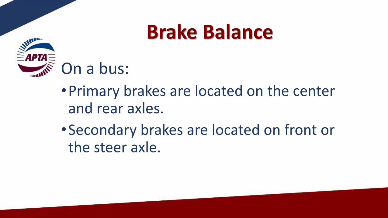
Brake Balance
On a bus:•Primary brakes are located on the center and rear axles.
•Secondary brakes are located on front or the steer axle.

Brake Balance
•Brake temperature should be 50 degrees cooler on the front than the rear
•Brake temperature for the same axle should be about the same for each side
•Normal operating temperature for the brake system should be approximately: Front 240 degrees Rear 280 degrees

Transmission Retarder
•Retarder is a third brake•Retarder creates braking force on drive axle
only•Retarder extends braking life on both primary
and secondary brakes•Retarder lowers operating temperature on both
primary and secondary brakes equally•Transmission oil level must be at full level to
operate correctly

65
Any Questions?
Please e-mail the questions to [email protected]
The APTA Brake and Chassis Work Group and the APTA Bus Standards Committee would like to thank you for joining our Webinar.
Pictures, drawings and technical information courtesy of MAN, ZF, Meritor, Knorr-Bremse, Bendix, MGM Brakes, LA Metro,
Omnitrans, MBTA, Custom Training Aids, Link Engineering, and other members of the APTA Brake and Chassis Work Group