aida design review davide braga steve thomas asic design group 9 june 2009
TRANSCRIPT

AIDA design reviewDavide Braga
Steve Thomas
ASIC Design Group
9 June 2009
9 June 2009 AIDA design review 2
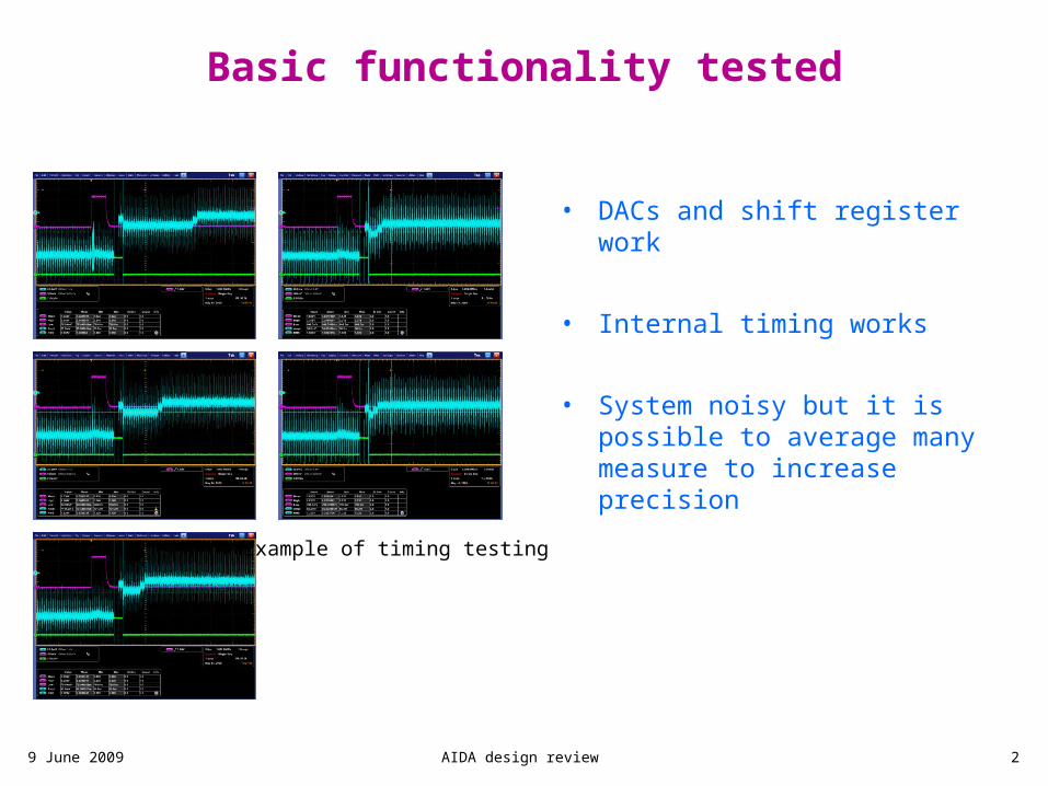
Basic functionality tested
• DACs and shift register work
• Internal timing works
• System noisy but it is possible to average many measure to increase precision
Example of timing testing
9 June 2009 AIDA design review 3
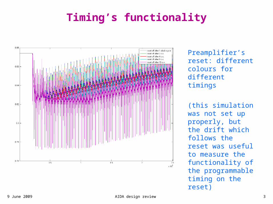
Timing’s functionality
Preamplifier’s reset: different colours for different timings
(this simulation was not set up properly, but the drift which follows the reset was useful to measure the functionality of the programmable timing on the reset)
0
12 4
816

9 June 2009 AIDA design review 4
Preamp & PeakHold linearity
Preamplifier’s and Peak Hold’s linearity <1% (possibly lower: precision of measurement limited)
0
12 4
816

9 June 2009 AIDA design review 5
Discriminator
discriminator output (blue line): fast rise time <2ns
0
12 4
816

9 June 2009 AIDA design review 6
Reset sequence (1)
0
12 4
816
input signal
analog output (preamp)
“data ready”
peak hold
Medium energy double implant (in yellow):
the reset sequence works correctly for the L/M energy channel, the data ready signal becomes active and everything is reset within microseconds

9 June 2009 AIDA design review 7
Reset sequence (2)
0
12 4
816
input signal
analog output (preamp)
“data ready”
peak hold
A full recovery can be achieved when the two signals are 10us apart.
However, this time is mainly due to the number of clock cycles it takes to run the reset sequence
9 June 2009 AIDA design review 8
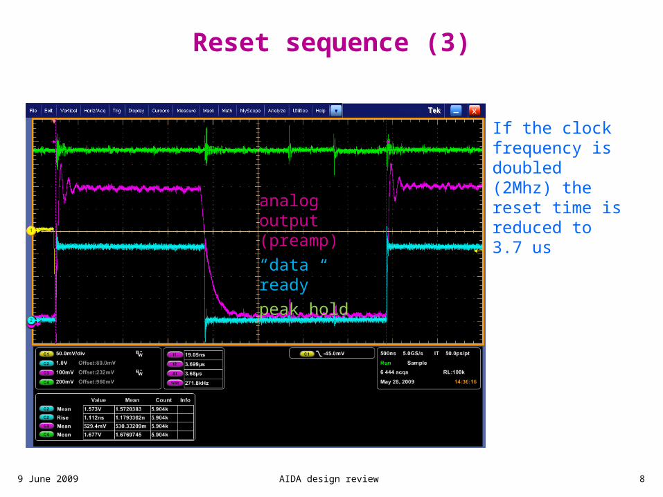
Reset sequence (3)
0
12 4
816
analog output (preamp)
“data ready”
peak hold
If the clock frequency is doubled (2Mhz) the reset time is reduced to 3.7 us
9 June 2009 AIDA design review 9
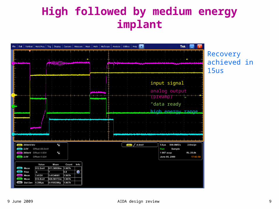
High followed by medium energy implant
0
12 4
816
input signal
analog output (preamp)
“data ready”
high energy range
Recovery achieved in 15us
9 June 2009 AIDA design review 10
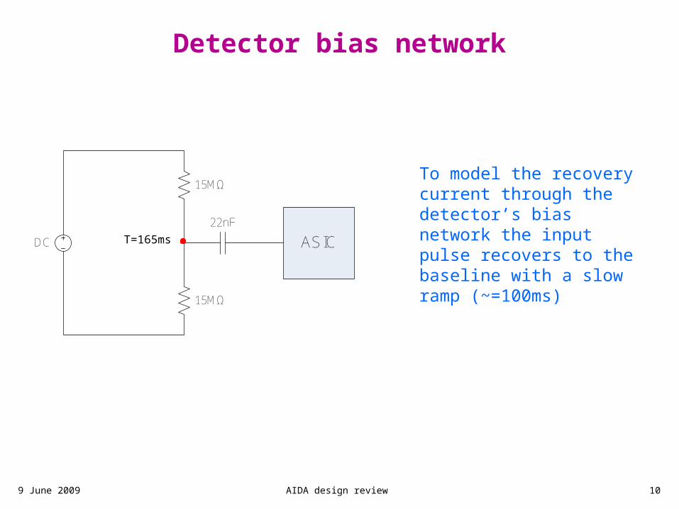
Detector bias network
0
12 4
816
To model the recovery current through the detector’s bias network the input pulse recovers to the baseline with a slow ramp (~=100ms)
22nF
15MΩ
15MΩ
DC ASICT=330msT=165ms
9 June 2009 AIDA design review 11
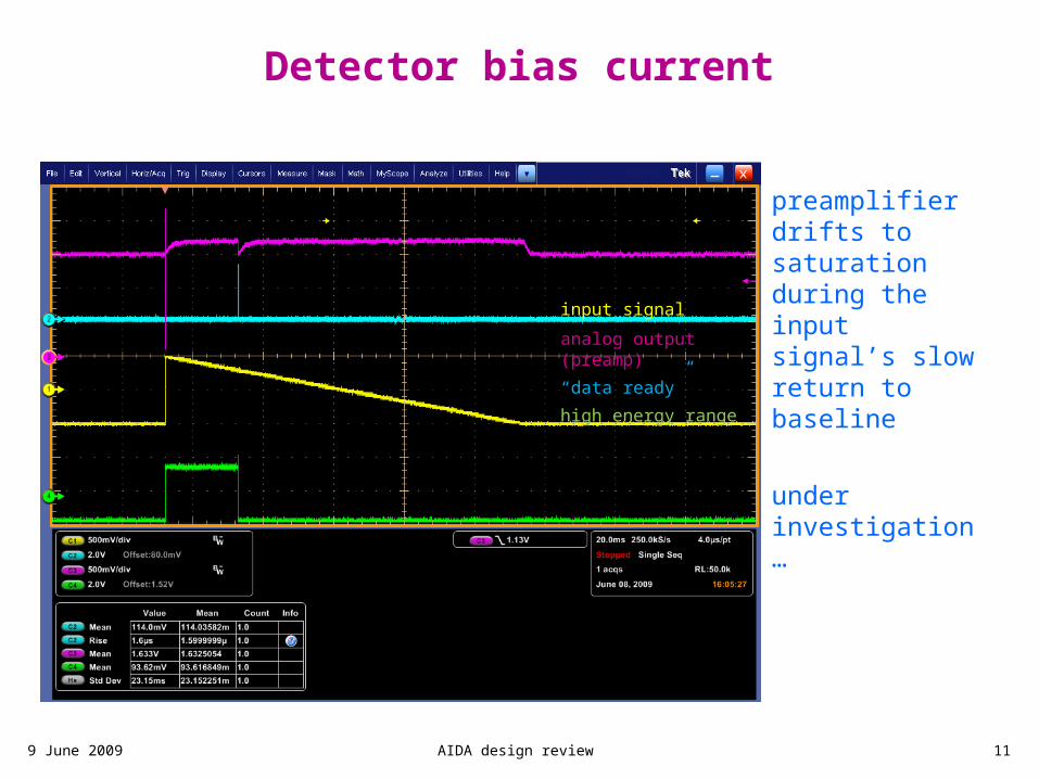
Detector bias current
0
12 4
816
input signal
analog output (preamp)
“data ready”
high energy range
preamplifier drifts to saturation during the input signal’s slow return to baseline
under investigation…
9 June 2009 AIDA design review 12
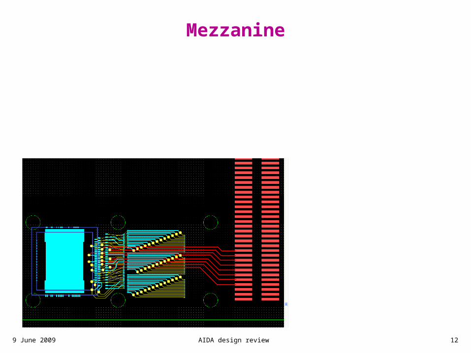
Mezzanine
0
12 4
816