agitation and mixing - … · flow pattern in agitated vessels the flow pattern in agitated vessels...
TRANSCRIPT

Agitation and Mixing
Agitation:
Agitation refers to the induced motion of a material in a specified way,
usually in a circulatory pattern inside some sort of container. Purpose is to
make homogeneous phase.
Mixing:
Mixing is the random distribution, into and through one another, of two or
more initially separate phases.
A single homogeneous material, such as tankful of cold water, can be
agitated, but it can’t be mixed until some other material (such as a quantity
of hot water or some powdered solid) is added to it.

Purposes of Agitation
Liquids are agitated for number of purposes which are given as follows
Suspending solid particles
Blending miscible liquids, e.g. Methyl alcohol and water
Dispersing a gas through the liquid in the form of small bubbles.
Dispersing a second liquid, immiscible with the first, to form an emulsion
or suspension of fine drops.
Promoting heat transfer between the liquid and a coil or jacket.

Agitated Vessel and Its Accessories


Flow Pattern in Agitated Vessels
The Flow Pattern in agitated vessels depends on the following factors;
Type of Impeller
Characteristics of the fluid
Size and proportions of the tank
Baffles
Agitator
The velocity of the fluid at any point in the tank has three components and overall flow
pattern in the tank depends on the variations in these three components.
Radial Component (It acts in a direction perpendicular to the shaft of the impeller)
Longitudinal Component (It acts in a direction parallel with the shaft)
Tangential / Rotational Component (It acts in a direction tangent to a circular path
around the shaft)

Vertically Mounted Shaft
Radial and Tangential components are in horizontal plane
Longitudinal component is in vertical plane
Radial and longitudinal are useful for mixing action
Tangential component is generally disadvantageous when shaft is vertically mounted.
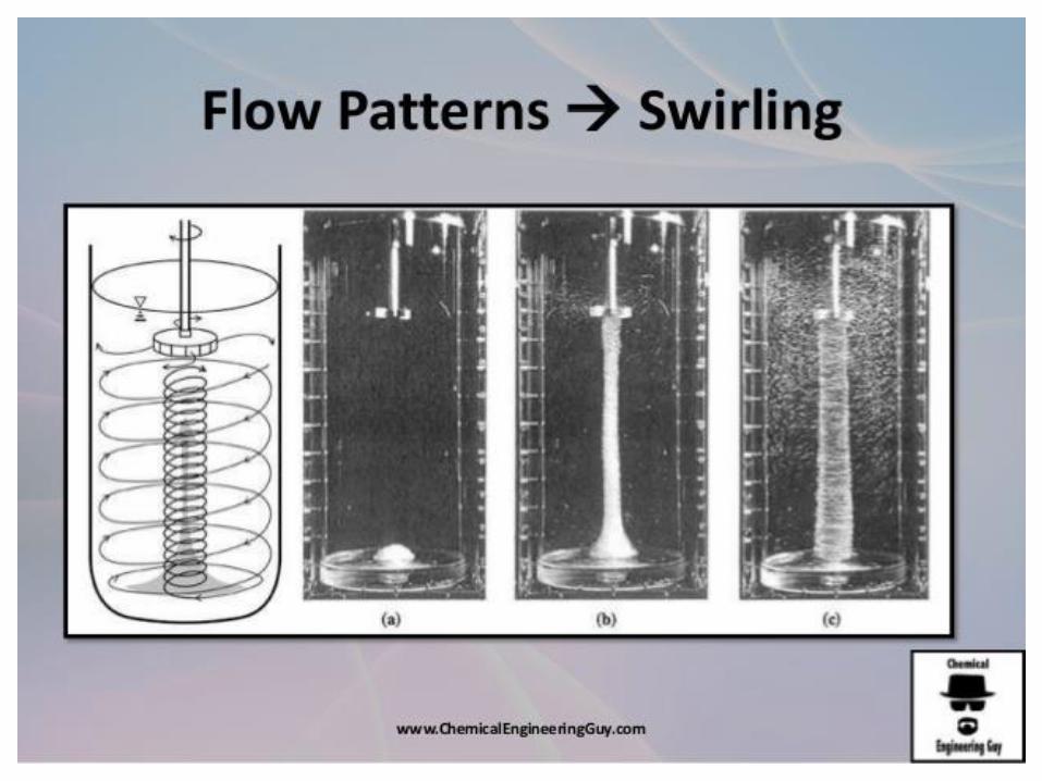
Tangential component follows a circular path around the shaft and creates a vortex in
the liquid.
If the solid particles are present in the liquid, circulatory currents tends to throw the
particles to the outside by centrifugal force and they move downward and to the
Centre of the tank at the bottom.
In an un baffled vessel circulatory flow is induced by all types of impellers i.e. axial
or radial
For strong swirling, flow pattern is same regardless of design of Impeller and at high
speed the vortex may be so deep to reach at the impeller surface.


• Prevention of swirling
Swirling or circulatory flow can be prevented by any of three ways
a. In small tanks the impeller can be mounted off center (shaft is moved away
from center then tilted in a plane perpendicular to the direction of move)
b. In Large tanks, the agitator may be mounted in the side of the tank with
shaft in horizontal plane but at an angle with radius.
c. In large tanks with vertical agitators, swirling can be prevented by
installing baffles.
Four baffles are sufficient to prevent swirling and vortex formation (Even two
have a strong effect on swirling effect).
For turbines width of baffle need be no more than one-tweflth of vessel
diameter and for propellers no more than one eighteenth of tank diameter.
No baffles are required for side entering, inclined or off center propellers


Impellers
Impellers are divided into two major classes
Axial Flow Impellers (These generates current parallel with the axis of
impeller shaft)
Radial Flow Impellers (These generate currents in tangential or radial
directions)
Following are the three main types of impellers
Propellers
Paddles
Turbines
There are also various other subtypes of impellers but the above mentioned three
types solves perhaps 95% of all liquid agitated problems


Propellers
It is an axial flow, high speed impeller for liquids of low viscosity.
Smaller propellers runs at either 1150 or 1750 rev/min and larger ones can
run at 400 to 800 rev/min.
The flow currents leaving the impeller continue through the liquid in a
given direction until deflected by floor or wall of the vessel. The propeller
blades vigorously cut or shear the liquid.
A revolving propeller traces out a Helix in the fluid.
One full revolution of propeller (provided no slip between liquid and
Propeller) would move the liquid longitudinally a fixed distance depending
on the Angle of inclination of propeller blades. The ratio of this distance to
propeller diameter is known as Pitch of blade. A Propeller blade with pitch
1 is called square Pitch.

Pitch of impeller

Propellers rarely exceed 18 in. in diameter.
Sometimes two propellers work in opposite directions or in “push-pull” to create
highly turbulent zone.
In deep tank, two or more may be mounted on the same shaft
Propellers are used when strong vertical currents are desired e.g. when heavy solid
particles are to be kept in suspension.
They are not ordinarily used when viscosity of liquid is greater than 50P.

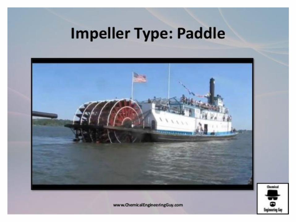
Agitator consists of flat paddle turning on vertical shaft
They pushed the liquid radially and tangentially with almost no vertical motion atimpeller unless blades are Pitched.
The currents they generates travel outward to the vessel wall and then either upward ordownward.
In deep tanks several paddles are mounted one above the other on the same shaft.
Anchors are useful for preventing deposits on a heat transfer surfaces (as in a jacketedprocesses) but hey are poor mixers.
Industrial paddle agitators turn at speeds between 20 and 150 rev/min
The total length of paddle impeller is typically 50 to 80percent of inside diameter ofvessel.
Width of blade is one-sixth to one-tenth its length.
Slow speed paddles gives mild agitation and can work in an unbaffled tanks but at higherspeeds baffles become necessary
Paddles


Turbines
They resembles multi bladed paddle agitators with short blades, turning at high speeds
on a shaft mounted centrally in the vessel.
Blades may be straight or curved, pitched or vertical.
Diameter of impeller turbine is smaller than with paddles, ranging from 30 to 50% of
vessel diameter.
The principle currents generated by turbines are radial and tangential ( the tangential
component induces vortexing and swirling which must be stopped by baffles


Draft tube
Draft tube is a cylindrical duct slightlylarger than the impeller diameter and ispositioned around the impeller
Used with axial impellers to direct thesuction and discharge flows.
The impeller draft tube system acts as alow efficiency axial flow pump
The top to bottom circulation flow is ofsignificance for flow controlled processes,suspension of solids and dispersion ofgases.
They are particularly useful for tall vesselshaving large ratio of height to diameter.

Standard Turbine Design
𝑺𝟏 =𝑫𝒂
𝑫𝒕=
𝟏
𝟑
𝑺𝟐 =𝑬
𝑫𝒕=
𝟏
𝟑
𝑺𝟑 =𝑳
𝑫𝒂=
𝟏
𝟒
𝑺𝟒 =𝑾
𝑫𝒂=
𝟏
𝟓
𝑺𝟓 =𝑱
𝑫𝒕=
𝟏
𝟏𝟐
𝑺𝟔 =𝑯
𝑫𝒕=
𝟏
𝟏

Power Consumption
The important consideration in the design of an agitated vessel is the power required to drive the
impeller.
• When flow is turbulent in the tank the flow can be obtained by “q” and “Ek” per unit volume
of fluid
“q” can be obtained from flow number
𝑁𝑄 =𝐴𝑐𝑡𝑢𝑎𝑙 𝐹𝑙𝑜𝑤 𝑓𝑟𝑜𝑚 𝑖𝑚𝑝𝑒𝑙𝑙𝑒𝑟
𝑇ℎ𝑒𝑜𝑟𝑒𝑡𝑖𝑐𝑎𝑙 𝑓𝑙𝑜𝑤 𝑓𝑟𝑜𝑚 𝑖𝑚𝑝𝑒𝑙𝑙𝑒𝑟=
𝑞
𝑛𝐷𝑎3
“Ek” per unit volume of fluid is equal to following
𝐸𝑘 =𝜌(𝑉2
′ )2
2𝑔𝑐

Where V2 is slightly smaller than the tip speed u2. ratio of 𝑉2′
𝑢2= 𝛼.And we know V2ʹ = απnDa
and the power requirement is
P = q x Ek
In Dimensionless form
The left hand side is the Power number Np.

Power Correlation
Power required to rotate a given impeller, the empirical correlations of power with other variables
of the system are needed. These can be represented in dimensionless form and are listed out as
follows;
Measurement of tank and Impeller
Distance of the impeller from the tank floor
The liquid depth
Dimensions of the baffles
Number and arrangement of the baffles
Number of blades in the impeller
The viscosity and density of the fluid
Speed of agitator
Dimensionless constant gc (because newton’s law is applicable)
Absence / Presence of swirling and vortex
Acceleration due to gravity when the liquid is lifted up (due to agitation) from certain
average height
Various linear measurements can all be converted to dimensionless ratios, called “shape
factors”, by dividing each of them by one of their number which is arbitrarily chosen as a
basis. Diameter of tank , Dt, or the diameter of impeller, Da, are the suitable choices for the
base measurement.
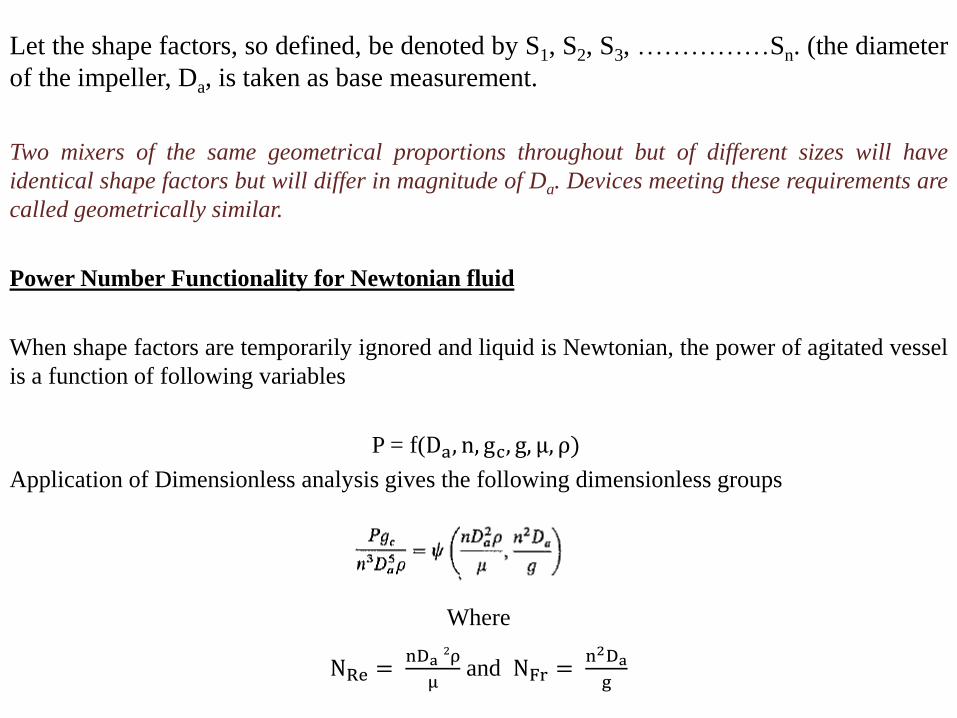
Let the shape factors, so defined, be denoted by S1, S2, S3, ……………Sn. (the diameter
of the impeller, Da, is taken as base measurement.
Two mixers of the same geometrical proportions throughout but of different sizes will have
identical shape factors but will differ in magnitude of Da. Devices meeting these requirements are
called geometrically similar.
Power Number Functionality for Newtonian fluid
When shape factors are temporarily ignored and liquid is Newtonian, the power of agitated vessel
is a function of following variables
P = f(Da, n, gc, g, μ, ρ)
Application of Dimensionless analysis gives the following dimensionless groups
Where
NRe =nDa
2ρ
μand NFr =
n2Da
g
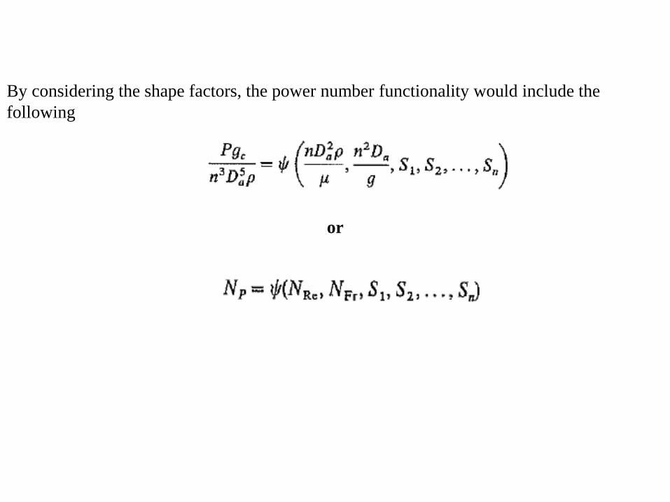
By considering the shape factors, the power number functionality would include the
following
or

Significance of Dimensionless Groups
Reynolds's number
Where u2 = Impeller tip speed = nπDa
This Reynolds's number calculated from the diameter and peripheral speed of impeller.
Power number
It’s the ratio of drag force acting on a unit area of impeller and the inertial stresses.
It is analogous to a friction factor or a drag coefficient
Froude Number
It’s the ratio of the inertial stress to the gravitational force per unit area acting on the fluid.
It appears in the fluid dynamic situations where there is significant wave motion on a liquid
surface.
it is used to study the vortex motion during scale up of mixer.
Flow number
It is used to find the pumping rate of the impeller.

Power Correlations For specific Impellers
To know the effect of geometry on the power requirement, the engineer should specify;
All shape factors
No. of baffles
No. of impeller blades
Pitch of impeller and number of blades (for propeller)

Curve A: Vertical blades with S4 = 0.2
Curve B: similar impeller with narrower blades (S4=0.125)
Curve C: For pitched blades turbine

Curve A: Three blade propeller centrally mounted in a baffle tank.
Propellers and pitched blade turbines draw considerably less power than a turbine with
vertical blades

Mathematical Procedure
for Un-baffled tanks at low Reynolds's Number• At low Reynolds number (below 300), the power curves for baffled and un-baffled tanks
are identical
• In this region the Reynolds's number, generally avoided in practice in un-baffled tanks, a
vortex forms and Froude number has an effect.
• Power number can be modified as follows:
• For given set of shape factors, the ‘m’ can be related to Reynolds's number by following
equation

Effect of System Geometry (Flat blade turbine operating at high
Reynolds's number)
Decreasing S1 (impeller diameter to tank diameter) increases Np when baffles are
few and narrow and decreases Np when baffles are many and wider.
With four baffles and S5 (baffle diameter to vessel diameter) set equal to 1/12,
changing S1 has almost no effect on the Np.
With S2 (height of impeller to diameter of tank) increases Np increases for disk
turbine and decreases considerably for pitched blades turbine.
For straight blade open turbine, the effect of changing S4 (Impeller width to
diameter of Impeller) depends on number of blades. For six blade S4 is directly
proportional to Np but for four blade turbine Np increases S41.25

With pitched blade turbine the effect of blade width on power consumption is
much smaller than with straight blade turbines.
Two straight blade turbines on the same shaft draw about 1.9times as much power
as one turbine alone, provided the spacing the two impellers is at least equal to the
impeller diameter. Two closely spaced turbines may draw as much as 2.4times as
much power as a single turbine.
The shape of the tank has little effect on the Np. The power consumed by
horizontal cylindrical vessels is same as in a vertical vessel for both baffled or un-
baffled.