agilent n2740a education training kit for 1000 series...
TRANSCRIPT

Agilent N2740A Education Training Kit for 1000 Series Oscilloscopes
Lab Manual
Notices© Agilent Technologies, Inc. 2008-2009
No part of this manual may be reproduced in any form or by any means (including electronic stor-age and retrieval or translation into a foreign language) without prior agreement and written con-sent from Agilent Technologies, Inc. as governed by United States and international copyright laws.
Manual Part NumberN2740-97001
EditionSecond edition, October 2009
Printed in U.S.A.
Agilent Technologies, Inc.1900 Garden of the Gods Rd. Colorado Springs, CO 80907 USA
WarrantyThe material contained in this document is provided “as is,” and is subject to being changed, without notice, in future editions. Further, to the maximum extent permitted by applicable law, Agi-lent disclaims all warranties, either express or implied, with regard to this manual and any information contained herein, including but not limited to the implied warranties of merchant-ability and fitness for a particular purpose. Agilent shall not be lia-ble for errors or for incidental or consequential damages in con-nection with the furnishing, use, or performance of this document or of any information contained herein. Should Agilent and the user have a separate written agreement with warranty terms covering the material in this doc-ument that conflict with these terms, the warranty terms in the separate agreement shall con-trol.
Technology Licenses The hardware and/or software described in this document are furnished under a license and may be used or copied only in accor-dance with the terms of such license.
Restricted Rights LegendIf software is for use in the perfor-mance of a U.S. Government prime contract or subcontract, Software is delivered and licensed as “Commercial computer soft-ware” as defined in DFAR 252.227-7014 (June 1995), or as a “commercial item” as defined in FAR 2.101(a) or as “Restricted computer software” as defined in FAR 52.227-19 (June 1987) or any equivalent agency regulation or contract clause. Use, duplication
or disclosure of Software is sub-ject to Agilent Technologies’ stan-dard commercial license terms, and non-DOD Departments and Agencies of the U.S. Government will receive no greater than Restricted Rights as defined in FAR 52.227-19(c)(1-2) (June 1987). U.S. Government users will receive no greater than Limited Rights as defined in FAR 52.227-14 (June 1987) or DFAR 252.227-7015 (b)(2) (November 1995), as appli-cable in any technical data.
Safety Notices
CAUTIONCAUTION
A CAUTION notice denotes a hazard. It calls attention to an operating procedure, prac-tice, or the like that, if not cor-rectly performed or adhered to, could result in damage to the product or loss of impor-tant data. Do not proceed beyond a CAUTION notice until the indicated conditions are fully understood and met.
WARNING
A WARNING notice denotes a hazard. It calls attention to an operating procedure, practice, or the like that, if not correctly performed or adhered to, could result in personal injury or death. Do not proceed beyond a WARNING notice until the indicated conditions are fully understood and met.
2

Agilent 1000 Series Oscilloscopes—Big Scope Features, Little Scope Price
The Agilent 1000 Series oscilloscopes feature:
• Up to 2 GSa/s sample rate and 20 kpts memory.
• Crisp and bright 5.7” color display with wide viewing angle and waveform viewing area—making it easy to view signals.
• Mask testing.
• Waveform recording and playback (sequence mode).
• Dedicated, color-coded vertical controls make it easy to access the most common functions.
• Built-in help, menus, front panel overlay template, and manual offered in eleven languages.
• Autoscale helps you quickly display signals, automatically setting the controls.
• Automatic measurements (23) or manual cursor measurements.
• Zoomed time base display shows big picture and zoomed in view simultaneously.
• Built-in USB ports make it easy to save your setups, data, and screen images, print to PictBridge compliant printers, and connect to your PC.
• Small, light weight portable design—easy to carry around.
• Kensington lock for added security.
Education Training Kit for 1000 Series Oscilloscopes 3

About the Training Kit Board
Training Kit Board FeaturesThe N2740A education training kit board outputs 15 different types of signals, selectable via the MODE rotary dial switch.
Caution
Components on the training kit board are susceptible to electrostatic discharge (ESD). Please be careful to avoid electrostatic discharge when handling the board.
MODE OutputOn Channel Notes
0 Sine Wave 1
1 Square Wave 1
2 Data w/Glitch 1
3 Phase Shifted Sine Waves 1, 2 Use POT to adjust phase shift.
4 Single Shot Data 1 Use SWITCH to output single shot data.
5 Burst Data 1, 2 Intermittent glitch on CH1 after burst data.
6 Noisy Sine Wave 1
7 Ringing Pulse 1
8 Triangle Wave 1
9 Ramp Wave 1
A Square Waves w/Offset 1, 2
B FSK 1 Frequency modulated signal.
C I2C 1, 2 Inter-Integrated Circuit serial bus, CH1 = clock, CH2 = data.
D CAN 1, 2 Controller Area Network serial bus, CH1 = data, CH2 = drive signal.
E RS-232 1, 2 CH1 = Rx, CH2 = Tx.
4 Education Training Kit for 1000 Series Oscilloscopes

USB Cable Connection
ProbesUse the passive probes that are included with the oscilloscope (N2862A or N2863A).
You may need to compensate the passive probes. For more information, see the 1000 Series Oscilloscopes User’s and Service Guide.
Power provided byUSB connection.
Signal ProbePoints
Rotary MODESignal SelectionSwitch
Education Training Kit for 1000 Series Oscilloscopes 5

In This Manual
If you are experiencing the 1000 Series oscilloscope for the first time, begin with Lab 1, Using the Front Panel Controls. If you have a basic knowledge of the 1000 Series oscilloscope’s front-panel controls, begin with Lab 3.
Topic PageTime Allowance
Lab 1: Using the Front Panel Controls 7 5 min.
Lab 2: Making Measurements 15 5 min.
Lab 3: Using Waveform Math Functions 20 5 min.
Lab 4: Saving and Displaying a Reference Waveform
24 5 min.
Lab 5: Setting Up Triggers 26 10 min.
Lab 6: Using Acquisition Modes 34 5 min.
Lab 7: Mask Testing and Recording Waveforms 38 10 min.
Lab 8: Saving and Printing 43 5 min.
6 Education Training Kit for 1000 Series Oscilloscopes

Agilent N2740A Education Training Kit for 1000 Series Oscilloscopes
1Using the Front Panel Controls
Capturing and Viewing a Simple Signal 10Horizontal Controls 11Run Controls 12Vertical Controls 13Trigger Controls 13
The Agilent 1000 Series oscilloscopes have knobs, keys, and softkeys for horizontal, vertical, run control, and trigger settings.
7

1 Using the Front Panel Controls
.
Softkeys forselectingmenu items
Settings and status shown on screen border.
Built-in USB ports make it easyto save your work and updateoscilloscope firmware.
8 Education Training Kit for 1000 Series Oscilloscopes

Using the Front Panel Controls 1
Run Control
Selection knob, immediate action keys and special menusPush the knob to make a selection
Trigger levelknob andcontrols
Time/div and positionhorizontal controls
Vertical color-coded controlsfor each scope channel
Access built-in helpby pressing Help andthen the key or knobin question
Education Training Kit for 1000 Series Oscilloscopes 9

1 Using the Front Panel Controls
Capturing and Viewing a Simple Signal
1 Connect the USB cable from the front panel USB host port on the oscilloscope to the USB IN connector on the training kit board.
2 Connect the channel 1 probe to the test points labeled CH1 and GND.
3 Rotate the MODE dial to position 0 (Sine wave).
4 Press the [Default Setup] key on the front panel. When the Default menu appears, press [Menu On/Off] to turn off the menu.
The oscilloscope is now set in the factory default configuration – just as it left the factory. Since the oscilloscope may have been used in a variety of applications by a variety of people, it is a good measurement procedure to put the oscilloscope in a known starting mode (Default Setup). This will make it easy to duplicate measurements as no special conditions will be set.
5 Press [AutoScale]. When the AUTO menu appears, press [Menu On/Off] to turn off the menu.
The oscilloscope analyzes all active channels, turning them on and setting the time base, V/div, and trigger conditions for an initial display.
Press
Press
10 Education Training Kit for 1000 Series Oscilloscopes

Using the Front Panel Controls 1
Horizontal Controls
1 Turn the large knob in the horizontal control section clockwise and counterclockwise to control the time/div setting of the horizontal axis. Observe the changes in the displayed signal. The current time base setting is displayed at the top of the screen in the display border.
2 Turn the small knob in the horizontal control section to move the waveform horizontally from the trigger point. Push this knob to return the trigger point to the center of the screen.
3 Set the time base 500 µs/div.
4 Press the [Menu/Zoom] key to display the Horizontal menu. Note the Zoom setting and Time Base modes of Y-T, X-Y, and Roll.
For instant HELP on any topic, press the [Help] key; then, press the key, softkey, or knob that you would like more information about.
5 Press the Zoom softkey and observe the split-screen – this mode shows the big picture on top and an expanded view on the bottom.
6 Turn the large time base knob clockwise to make the window on top smaller.
7 Press the Zoom softkey again to return to the original display.
Note: At any time, to return to the original setup, press [AutoScale].
Turn to control horizontal position
Turn to control time/div
Press
Time basesettings
Education Training Kit for 1000 Series Oscilloscopes 11

1 Using the Front Panel Controls
Run Controls
When the oscilloscope is turned on, or if [AutoScale] is pressed, the acquisition will be set to [Run]. At any time you may [Stop] the acquisition process to examine a signal in detail or to save it.
1 Press [AutoScale] to return to simple setup.
2 Set time base to 2 ms/div.
3 Press the [Single] key to make a single acquisition and stop the acquisition process.
4 Use the large Horizontal knob to zoom in on the waveform.
Acquisition record lengths are the same with “single” or “running” acquisitions.
Press tostop
acquisition
Capture the bigpicture thenzoom in fordetailed analysis.
12 Education Training Kit for 1000 Series Oscilloscopes

Using the Front Panel Controls 1
Vertical Controls
1 Press [AutoScale] to return to simple setup.
2 Turn the large yellow knob in the Vertical section to control the V/div setting. The V/div setting is displayed in the lower left hand corner of the screen in the display border. Knobs are color coded to match the waveform color.
3 Press the [1] key to display the channel 1 menu. Press again to turn the channel off and then on.
4 Turn the small yellow knob to control the vertical offset position of the waveform, moving it up or down.
Trigger Controls
1 Press [AutoScale] to return to a simple setup.
2 Rotate the trigger level knob up and down. The trigger level is displayed as it is adjusted.
If the trigger level is above or below the signal, the oscilloscope will force a trigger and display a waveform when in Auto mode. Auto is a useful trigger mode to use when unsure of the exact waveform, as activity will be displayed making it easy to better configure the oscilloscope’s settings and trigger level.
3 Press the [Menu] key in the trigger section.
4 Press the [Help] key; then press the Sweep softkey to read more about the Auto and Normal trigger sweep.
5 Set the trigger sweep to Normal. Move the trigger level up and down.
Observe that the oscilloscope only triggers when a valid trigger condition exists – this is the trigger mode to use when you want to set a specific trigger condition and capture waveforms only when those conditions are met.
Press
Movetriggerlevel upand downon signal
Education Training Kit for 1000 Series Oscilloscopes 13

1 Using the Front Panel Controls
Auto sweep forces triggersif the trigger condition is notmet and shows untriggeredwaveform activity.
Normal sweep waits for awaveform that meets thetrigger conditions beforedisplaying any activity.
14 Education Training Kit for 1000 Series Oscilloscopes

Agilent N2740A Education Training Kit for 1000 Series Oscilloscopes
2Making Measurements
Automatic Voltage and Time Measurements 15Hardware Frequency Counter 17Manual Cursor Measurements 18Phase Measurements and the X-Y Time Base 19
With the 1000 Series oscilloscopes, you can make 23 different automatic voltage and time measurements. You can also display the hardware frequency counter. And, you can use cursors to make manual measurements.
Automatic Voltage and Time Measurements
1 Connect the channel 1 probe to the test points labeled CH1 and GND.
2 Rotate the MODE dial to position 7 (Ringing Pulse).
3 Press [Default Setup].
4 Press [AutoScale].
5 Press the [Measure] key.
6 In the Measure menu, press Voltage; then, turn the selection knob to choose Vpp, and push the selection knob.
The peak-to-peak voltage measurement appears at the bottom of the display where up to three of the most recent measurements are shown. (The Clear softkey removes measurements from the display.)
Note that the [Measure] key is lit when measurements are displayed.
Press
15

2 Making Measurements
7 Press the [Cursors] key.
8 In the Cursors menu, press Mode; then, turn the selection knob to choose Auto and push the selection knob.
Now, cursors for the latest automatic voltage or time measurement are displayed (and the [Cursors] key is lit).
9 Press the [Measure] key.
10 In the Measure menu, press Time; then, turn the selection knob to choose Freq, and push the selection knob.
Now, two measurements are displayed, and cursors are shown for the frequency measurement.
Press
16 Education Training Kit for 1000 Series Oscilloscopes

Making Measurements 2
11 In the Measure menu, press 1/2 to go to the next page of menu items; then, press Display All.
Now, all the single-waveform measurements are displayed at once.
Hardware Frequency Counter
12 In the Measure menu, press Counter to turn on the hardware frequency counter.
The 6-digit hardware frequency counter value appears at the top of the display.
The counter operates on the currently selected trigger source. It uses the trigger comparator to count the number of cycles within a period of time (known as the gate time), so the trigger level must be set correctly.
13 Press the Display All and Counter softkeys again to turn these measurements off and remove them from the display.
Education Training Kit for 1000 Series Oscilloscopes 17
2 Making Measurements
Manual Cursor Measurements
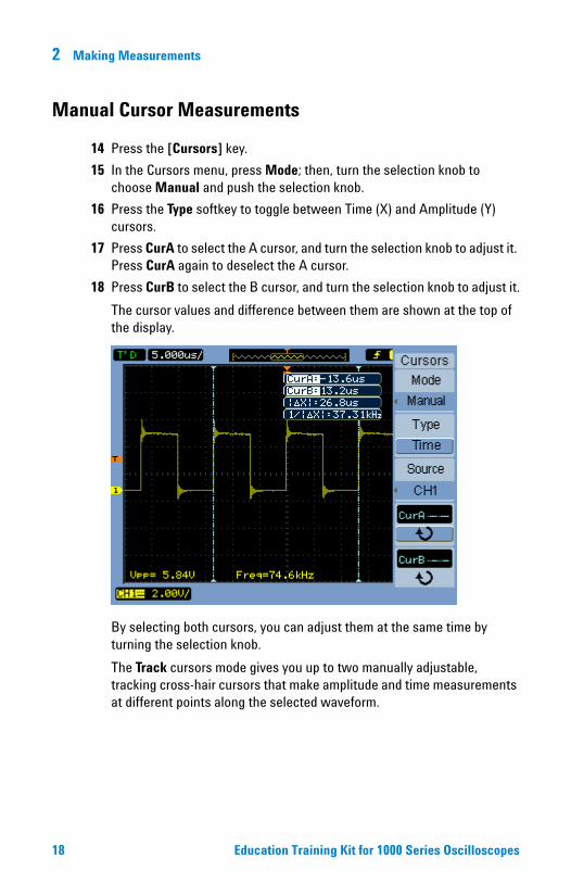
14 Press the [Cursors] key.
15 In the Cursors menu, press Mode; then, turn the selection knob to choose Manual and push the selection knob.
16 Press the Type softkey to toggle between Time (X) and Amplitude (Y) cursors.
17 Press CurA to select the A cursor, and turn the selection knob to adjust it. Press CurA again to deselect the A cursor.
18 Press CurB to select the B cursor, and turn the selection knob to adjust it.
The cursor values and difference between them are shown at the top of the display.
By selecting both cursors, you can adjust them at the same time by turning the selection knob.
The Track cursors mode gives you up to two manually adjustable, tracking cross-hair cursors that make amplitude and time measurements at different points along the selected waveform.
18 Education Training Kit for 1000 Series Oscilloscopes
Making Measurements 2
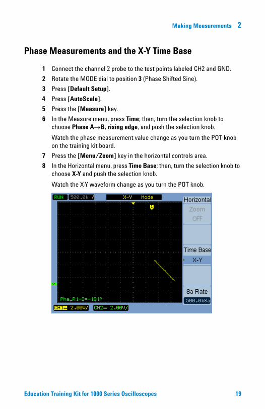
Phase Measurements and the X-Y Time Base
1 Connect the channel 2 probe to the test points labeled CH2 and GND.
2 Rotate the MODE dial to position 3 (Phase Shifted Sine).
3 Press [Default Setup].
4 Press [AutoScale].
5 Press the [Measure] key.
6 In the Measure menu, press Time; then, turn the selection knob to choose Phase AB, rising edge, and push the selection knob.
Watch the phase measurement value change as you turn the POT knob on the training kit board.
7 Press the [Menu/Zoom] key in the horizontal controls area.
8 In the Horizontal menu, press Time Base; then, turn the selection knob to choose X-Y and push the selection knob.
Watch the X-Y waveform change as you turn the POT knob.
Education Training Kit for 1000 Series Oscilloscopes 19

Agilent N2740A Education Training Kit for 1000 Series Oscilloscopes
3Using Waveform Math Functions
Addition/Subtraction/Multiplication Math Functions 20FFT Math Function 22
The 1000 Series oscilloscopes let you display the addition, subtraction, and multiplication of two input channel waveforms. You can also view a waveform’s FFT to see its frequency components. These are known as waveform math functions.
Addition/Subtraction/Multiplication Math Functions
1 Connect the channel 1 probe to the test points labeled CH1 and GND.
2 Connect the channel 2 probe to the test points labeled CH2 and GND.
3 Rotate the MODE dial to position 3 (Phase Shifted Sine).
4 Press [Default Setup].
5 Press [AutoScale].
6 Press the [Math] key.
7 In the Math menu, press Operate; then, turn the selection knob to choose A - B, and push the selection knob.
Press
20

Using Waveform Math Functions 3
Watch the subtraction waveform change as you turn the POT knob on the training kit board.
The Math menu also lets you:
• Select any two input channels for the A and B waveform sources.
• Invert the voltage values of the math waveform.
• Vertically position the math waveform using the selection knob.
• Vertically scale the math waveform using the selection knob.
Education Training Kit for 1000 Series Oscilloscopes 21

3 Using Waveform Math Functions
FFT Math Function
1 Rotate the MODE dial to position 1 (Square wave, 75 kHz).
2 Press [Default Setup].
3 Press [AutoScale].
4 Adjust the horizontal scale to 50.0 s/div.
5 Press the [Math] key.
6 In the Math menu, press Operate; then, turn the selection knob to choose FFT, and push the selection knob.
7 Turn the horizontal scale knob to adjust the horizontal scale to 125 kHz/div.
8 Press 1/2 to go to the next page of menu items; press the softkey, and turn the selection knob to adjust the FFT waveform’s vertical scale to 200 mV/div.
You can see the square wave’s frequency components are at the fundamental frequency and the odd harmonics.
In FFT mode, the Math menu also lets you:
• Select the input source channel.
• Choose the FFT window type from: Rectangle, Hanning, Hamming, and Blackman.
• Switch between a split-screen display and a full-screen display.
22 Education Training Kit for 1000 Series Oscilloscopes
Using Waveform Math Functions 3
• Vertically position the FFT waveform using the selection knob.
• Vertically scale the FFT waveform using the selection knob.
• Switch between Vrms and dBVrms scale.
You can also use the FFT waveform math function on the training kit board’s FSK signal (MODE dial position B) to see the frequencies in the frequency modulated waveform.
Education Training Kit for 1000 Series Oscilloscopes 23

Agilent N2740A Education Training Kit for 1000 Series Oscilloscopes
4Saving and Displaying a Reference Waveform
The 1000 Series oscilloscopes let you save and display a reference waveform in order to compare it with other captured waveforms.
1 Connect the channel 1 probe to the test points labeled CH1 and GND.
2 Rotate the MODE dial to position 1 (Square wave, 75 kHz).
3 Press [Default Setup].
4 Press [AutoScale].
5 Press the [REF] key.
6 In the REF menu, press Save.
The reference waveform is displayed.
7 Press 1/2 to go to the next page of menu
items; press the softkey, and turn the selection knob to adjust the reference waveform’s vertical position.
The horizontal scale and position knobs operate on the reference waveform when it is displayed.
8 Rotate the MODE dial to position 7 (Ringing Pulse).
Now, you can compare the square waveform and the ringing pulse waveform.
Press
24

Saving and Displaying a Reference Waveform 4
The REF menu also lets you:
• Select the source when saving a reference waveform.
• Select an internal or external (USB drive) location when saving a reference waveform.
• Import or export reference waveforms to an external USB drive location.
• Vertically position the reference waveform using the selection knob.
• Vertically scale the reference waveform using the selection knob.
• Reset the reference waveform to its scale and position when originally saved.
Education Training Kit for 1000 Series Oscilloscopes 25

Agilent N2740A Education Training Kit for 1000 Series Oscilloscopes
5Setting Up Triggers
Triggering on Both Edges, Displaying Infinite Persistence 26Triggering on Single Shot Pulses 27Adjusting Trigger Sensitivity 28Finding Glitches with a Pulse Trigger, Displaying Zoomed Time
Base 30Triggering on a Pattern 31Triggering on Non-Synchronized Signals in Alternate Mode 32
The 1000 Series oscilloscopes provide many triggering options for capturing waveforms. You can specify trigger sweep, coupling, sensitivity, and holdoff, and you can use these triggering modes:
• Edge — occurs when the input passes through a specified voltage level with the specified slope.
• Pulse — used to find pulses with certain widths.
• Video — used to trigger on fields or lines for standard video waveforms.
• Pattern — used to trigger on patterns from all input channels.
• Alternate — used to trigger on non-synchronized signals.
Triggering on Both Edges, Displaying Infinite Persistence
1 Connect the channel 1 probe to the test points labeled CH1 and GND.
2 Rotate the MODE dial to position 7 (Ringing Pulse).
3 Press [Default Setup].
4 Press [AutoScale].
5 Adjust the horizontal scale to 2 s/div.
6 Press the [Menu] key.
7 In the Trigger menu, press Slope three times to select both edges.
8 Press the [Display] key.
9 In the Display menu, press Persist to turn on “Infinite” persistence.
Movetriggerlevel upand downon signal
26

Setting Up Triggers 5
Being able to trigger on both edges of a waveform and use infinite persistence gives you a display similar to an eye diagram.
Triggering on Single Shot Pulses
1 Connect the channel 1 probe to the test points labeled CH1 and GND.
2 Rotate the MODE dial to position 4 (Single Shot Data).
In the single shot mode, the training kit board outputs single shot data when its SWITCH button is pressed.
3 Press [Default Setup].
4 Press [AutoScale].
5 Adjust the trigger level to 2.0 V.
6 Adjust the channel 1 vertical position to -2.0 V.
7 Adjust the horizontal scale to 2.0 s/div.
8 Press the [Single] key.
Notice that “WAIT” appears in the upper left corner of the display because the oscilloscope is waiting to find the trigger condition.
9 Press the training kit board’s SWITCH button.
The desired single shot data is now captured.
Education Training Kit for 1000 Series Oscilloscopes 27

5 Setting Up Triggers
Note that “STOP” appears in the upper left corner of the display after the single acquisition has completed.
Adjusting Trigger Sensitivity
1 Connect the channel 1 probe to the test points labeled CH1 and GND.
2 Rotate the MODE dial to position 6 (Noisy Sine).
3 Press [Default Setup].
4 Press [AutoScale].
5 Adjust the channel 1 vertical scale to 500 mV/div.
6 Adjust the channel 1 vertical position to -2.0 V.
7 Adjust the horizontal scale to 200 s/div.
8 Press the [Menu] key.
9 In the Trigger menu, press Set Up.
In the Set Up menu, press Sensitivity; then, turn the selection knob to enter 0.1 div.
Notice the oscilloscope appears to be triggering on both edges of the waveform when it should be triggering on the rising edge only. Actually, the noise in the waveform has a rising edge that is also triggering the oscilloscope.
28 Education Training Kit for 1000 Series Oscilloscopes

Setting Up Triggers 5
10 Turn the selection knob to enter a trigger sensitivity of 0.7 div.
Now, it takes more of a change in the waveform to trigger the oscilloscope, and only the rising edge of the sine wave (not the noise) triggers the oscilloscope.
With the training kit board’s noisy sine waveform, you can also turn on HF Reject to attenuate frequencies above 100 kHz. With the higher frequencies attenuated, the oscilloscope will trigger on the rising edge of the sine wave at the default sensitivity of 0.3 div.
Education Training Kit for 1000 Series Oscilloscopes 29
5 Setting Up Triggers
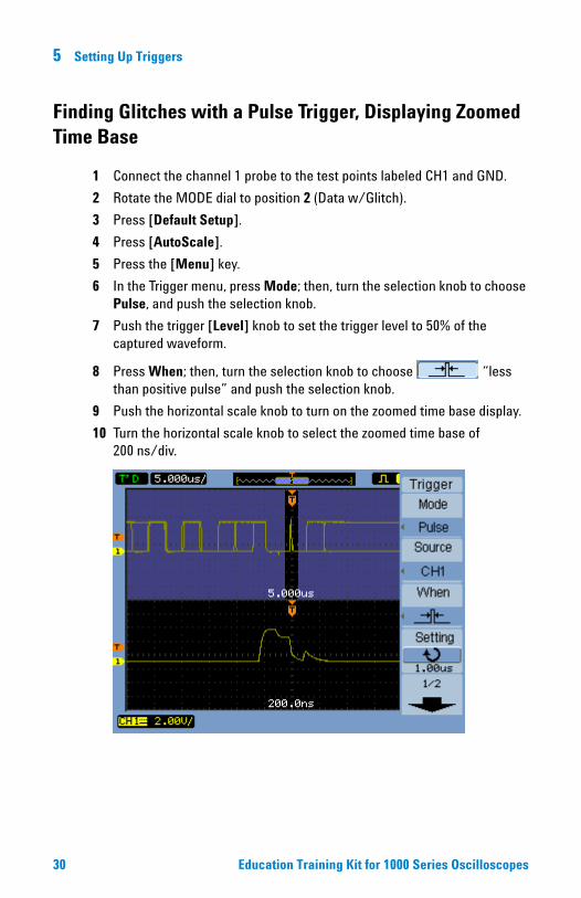
Finding Glitches with a Pulse Trigger, Displaying Zoomed Time Base
1 Connect the channel 1 probe to the test points labeled CH1 and GND.
2 Rotate the MODE dial to position 2 (Data w/Glitch).
3 Press [Default Setup].
4 Press [AutoScale].
5 Press the [Menu] key.
6 In the Trigger menu, press Mode; then, turn the selection knob to choose Pulse, and push the selection knob.
7 Push the trigger [Level] knob to set the trigger level to 50% of the captured waveform.
8 Press When; then, turn the selection knob to choose “less than positive pulse” and push the selection knob.
9 Push the horizontal scale knob to turn on the zoomed time base display.
10 Turn the horizontal scale knob to select the zoomed time base of 200 ns/div.
30 Education Training Kit for 1000 Series Oscilloscopes

Setting Up Triggers 5
Triggering on a Pattern
1 Connect the channel 1 probe to the test points labeled CH1 and GND.
2 Connect the channel 2 probe to the test points labeled CH2 and GND.
3 Rotate the MODE dial to position C (I2C, Inter-Integrated Circuit).
4 Press [Default Setup].
5 Press [AutoScale].
6 Adjust the vertical scale on both channels to 2 V/div.
7 Adjust the horizontal scale to 5.0 s/div.
8 Press the [Menu] key.
9 In the Trigger menu, press Mode; then, turn the selection knob to choose Pattern, and push the selection knob.
10 Set up the channel 1 trigger value:
a Press Channel; then, turn the selection knob to choose CH1, and push the selection knob.
b Press Code; then, turn the selection knob to choose L, and push the selection knob.
c Adjust the trigger level to 2 V.
11 Set up the channel 2 trigger value:
a Press Channel; then, turn the selection knob to choose CH2, and push the selection knob.
b Press Code; then, turn the selection knob to choose H, and push the selection knob.
c Adjust the trigger level to 2 V.
12 Leave all the remaining channel trigger values as don’t cares (X).
13 Press Sweep to select “Normal”.
Education Training Kit for 1000 Series Oscilloscopes 31

5 Setting Up Triggers
Triggering on Non-Synchronized Signals in Alternate Mode
1 Connect the channel 1 probe to the test points labeled CH1 and GND.
2 Connect the channel 2 probe to the test points labeled CH2 and GND.
3 Rotate the MODE dial to position C (I2C, Inter-Integrated Circuit).
4 Press [Default Setup].
5 Press [AutoScale].
6 Adjust the vertical scale on both channels to 2 V/div.
7 Press the [Menu] key.
8 In the Trigger menu, press Mode; then, turn the selection knob to choose Alternate, and push the selection knob.
9 Set up the channel 1 trigger and horizontal scale:
a Press Select to select CH1.
b Press Type; then, turn the selection knob to choose Edge, and push the selection knob.
c Press 1/2 to go to the next page of menu items.
d Press Slope to choose “falling edge”.
e Adjust the trigger level to 2 V.
32 Education Training Kit for 1000 Series Oscilloscopes

Setting Up Triggers 5
f Adjust the horizontal scale to 20 s/div.
10 Set up the channel 2 trigger and horizontal scale:
a Press 2/2 to go to the previous page of menu items.
a Press Select to select CH2.
b Press Type; then, turn the selection knob to choose Pulse, and push the selection knob.
c Press 1/2 to go to the next page of menu items.
d Press When; then, turn the selection knob to choose “negative pulse greater than”, and push the selection knob.
e Press Setting; then, turn the selection knob to enter 100 s.
f Adjust the trigger level to 2 V.
g Adjust the horizontal scale to 100 s/div.
The channel 1 and channel 2 signals are captured using different triggers and displayed in different horizontal scales.
Education Training Kit for 1000 Series Oscilloscopes 33

Agilent N2740A Education Training Kit for 1000 Series Oscilloscopes
6Using Acquisition Modes
Averaging to Reduce Noise on Repetitive Waveforms 34Peak Detect to Capture Narrow Excursions 36
The previous exercises in this manual use the “Normal” acquisition mode, where acquisitions are made and displayed one after the other. The 1000 Series oscilloscopes also have these acquisition modes:
• Average — acquisitions are made, and the running average over the specified number of acquisitions is displayed. This lets you remove random noise from the waveform and improve measurement accuracy.
In Normal or Average acquisition modes, at longer horizontal time/div settings, the oscilloscope’s analog-to-digital converter samples at a rate that yields more samples than can be stored in a limited amount of oscilloscope memory. Consequently, samples are thrown away (decimated), and you can miss narrow excursions on a signal.
• Peak Detect — acquisitions are made at the fastest sample rate, and the minimum and maximum values for the period associated with the memory and time/div setting are stored. This way, you can capture narrow excursions on a signal at longer horizontal time/div settings.
Averaging to Reduce Noise on Repetitive Waveforms
1 Connect the channel 1 probe to the test points labeled CH1 and GND.
2 Rotate the MODE dial to position F (Unused).
3 Press [Default Setup].
4 Press [AutoScale].
5 Adjust the vertical scale to 50 mV/div.
You can see random noise on the input.
34

Using Acquisition Modes 6
6 Press [Acquire].
7 In the Acquire menu, press Acquisition; then, turn the selection knob to choose Average, and push the selection knob.
8 Press Averages; then, turn the selection knob to choose 32.
You can see how the random noise is removed from the input.
Education Training Kit for 1000 Series Oscilloscopes 35

6 Using Acquisition Modes
Peak Detect to Capture Narrow Excursions
1 Connect the channel 1 probe to the test points labeled CH1 and GND.
2 Rotate the MODE dial to position 5 (Burst Data).
3 Press [Default Setup].
4 Press [AutoScale].
5 Adjust the trigger level to 2.0 V.
6 Adjust the channel 1 vertical position to -1.5 V.
7 Adjust the horizontal scale to 200 ms/div.
Because the burst data is relatively narrow compared to the time/div setting (and effective sample rate), few of the bursts are displayed.
8 Press [Acquire].
9 In the Acquire menu, press Acquisition; then, turn the selection knob to choose Peak Detect, and push the selection knob.
Now, the bursts and other narrow excursions are displayed.
36 Education Training Kit for 1000 Series Oscilloscopes

Using Acquisition Modes 6
Education Training Kit for 1000 Series Oscilloscopes 37

Agilent N2740A Education Training Kit for 1000 Series Oscilloscopes
7Mask Testing and Recording Waveforms
Creating Masks 38Running the Mask Test 39Recording Waveforms 40Playing-Back Waveforms 41
The 1000 Series oscilloscope features include mask testing and recording waveforms. You can combine these features to record only waveforms that fail a mask test.
Creating Masks
1 Connect the channel 1 probe to the test points labeled CH1 and GND.
2 Rotate the MODE dial to position 5 (Burst Data).
3 Press [Default Setup].
4 Press [AutoScale].
5 Adjust the trigger level to 2.0 V.
6 Adjust the channel 1 vertical position to -1.5 V.
7 Adjust the horizontal scale to 2.0 s/div.
8 Adjust the horizontal position to 6.0 s.
9 Press [Utility].
10 In the Utilities menu, press 1/2 to go to the next page of menu items.
11 Press Mask Test.
12 In the Mask Test menu, press Enable Test to turn on the mask test feature.
13 Press 1/2 to go to the next page of menu items.
14 Press Mask Setting.
15 In the Mask menu, press Create Mask to create the mask.
38

Mask Testing and Recording Waveforms 7
Running the Mask Test16 Press 1/2 to go to the next page of menu items.
17 Press the return softkey at the bottom of the menu to return to the Mask Test menu.
18 Press StopOnOutput to turn off stopping on a mask failure.
Note that the output condition is set to Fail. In addition to stopping on the output condition, you can use the output condition when recording waveforms (using Sequence in the Acquire menu). This lets you record over an extended period only waveforms matching the output condition.
19 Press 2/2 to go to the previous page of menu items.
20 Press Msg Display to turn on the display of failing, passing, and total waveforms.
21 Press Operate to begin the mask test.
Education Training Kit for 1000 Series Oscilloscopes 39

7 Mask Testing and Recording Waveforms
Recording Waveforms
22 Press [Acquire].
23 In the Acquire menu, press Sequence.
24 In the Sequence menu, press Mode; then, turn the selection knob to choose Record, and push the selection knob.
25 Press Source; then, turn the selection knob to choose P/F-OUT, and push the selection knob.
This selects the mask test’s output condition as the source for waveform recording.
26 Press End Frame; then, turn the selection knob to choose 50.
27 Press Operate to begin recording waveforms.
40 Education Training Kit for 1000 Series Oscilloscopes
Mask Testing and Recording Waveforms 7
28 Press Operate again to stop recording waveforms.
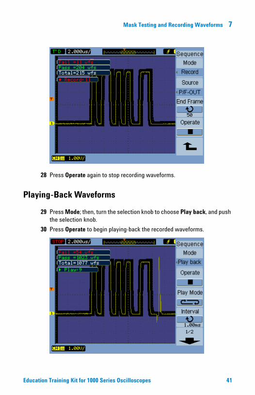
Playing-Back Waveforms
29 Press Mode; then, turn the selection knob to choose Play back, and push the selection knob.
30 Press Operate to begin playing-back the recorded waveforms.
Education Training Kit for 1000 Series Oscilloscopes 41

7 Mask Testing and Recording Waveforms
31 Press Operate again to stop the play-back.
Note that you can:
• Play-back in continuous and one-time modes.
• Change the interval between waveforms as they are played-back.
• Look at recorded waveforms individually using the Current Frame menu item (after pressing 1/2 to go to the next page of menu items).
• Save and recall recorded waveforms using the Storage mode.
42 Education Training Kit for 1000 Series Oscilloscopes

Agilent InfiniiVision 7000 Series Oscilloscopes Evaluation Kit Guide
8Saving and Printing
Saving and Recalling Waveforms and Setups 44Saving Screen Images and CSV Format Data 44Printing Screen Images 45
With the 1000 Series oscilloscopes, you can:
• Save/recall oscilloscope waveforms and setups to/from internal storage locations or external USB drive locations.
• Save screen images and CSV format (comma-separated value) waveform data to external USB drive locations.
• Print screen images to PictBridge compatible printers.
Pressto
Pressto
save andrecall
43Agilent Technologies

8 Saving and Printing
Saving and Recalling Waveforms and Setups
1 Press [Save/Recall].
2 In the Save/Recall menu, press Storage; then, turn the selection knob to choose Waveform or Setups and push the selection knob.
3 Press Internal to save to (or load from) one of the 10 internal storage locations, or press External to save to (or load from) a location on a USB drive.
Saving Screen Images and CSV Format Data
1 Press [Save/Recall].
2 In the Save/Recall menu, press Storage; then, turn the selection knob to choose 8-Bitmap, 24-Bitmap, PNG, or CSV and push the selection knob.
3 Press External to save to a location on a USB drive.
Note that:
• You can turn on Para Save to oscilloscope parameters in an accompanying ASCII test file.
• With CSV (comma-separated value) format, you can choose “Displayed” or “Maximum” Data Depth.
44 Agilent InfiniiVision 7000 Series Oscilloscope Evaluation Kit Guide

Saving and Printing 8
Printing Screen Images
PictBridge compliant printers are connected to the square USB device port on the back panel.
1 Press [Print].
2 In the Print menu, select the printing options.
3 Press Print to start the print.
Agilent InfiniiVision 7000 Series Oscilloscope Evaluation Kit Guide 45

8 Saving and Printing
46 Agilent InfiniiVision 7000 Series Oscilloscope Evaluation Kit Guide

Recommended Probes and Accessories
Optional accessories:
• N2738A – Soft carrying case for 1000 Series.• N2739A – Rackmount kit for 1000 Series.• N2740A – Education training kit for 1000 Series.• U3000A – Electronic instrument training kit.
Recommended probes:
• N2862A – 150 MHz 10:1 passive probe (standard with 60 MHz/100 MHz models).
• N2863A – 300 MHz 10:1 passive probe (standard with 200 MHz models).
• 10070C – 20 MHz 1:1 passive probe.• 10076A – 250 MHz, 100:1, 4 kV passive probe.• N2771A – 50 MHz, 1000:1, 30 kV passive probe.• N2772A – 20 MHz, 1.2 kV differential probe (requires 9V
battery or N2773A power adapter).• 1146A – 100 kHz, 100A AC/DC current probe (requires
9V battery).
Software and drivers:
• IntuiLink toolbar connectivity – downloadable free from: www.agilent.com/find/intuilink
• National Instruments LabView Plug & Play driver downloadable free from the National Instruments web site.
For more information about the Agilent 1000 Series oscilloscopes, check out: www.agilent.com/find/DSO1000

Agilent Technologies, Inc. 2008-2009
Printed in U.S.A. 10/09Second edition, October 2009
*N2740-97001*N2740-97001
www.agilent.com
Agilent 1000 Series Oscilloscopes
Model Channels BandwidthMax. sample rate Memory
Other standard features
DSO1002A 2 60 MHz
2 GSa/s half channel*, 1 GSa/s each channel
20 kpts half channel*, 10 kpts each channel
• Dedicated controls for each channel.
• AutoScale.• Automatic and
cursor measurements.
• Front and back panel USB ports.
• Built-in help.
DSO1004A 4 60 MHz
DSO1012A 2 100 MHz
DSO1014A 4 100 MHz
DSO1022A 2 200 MHz
DSO1024A 4 200 MHz
* Half channel is when only one channel of channel pair 1-2 is turned on, or one channel of channel pair 3-4 is turned on.