agilent 6820 gas chromatograph - united states home | agilent
TRANSCRIPT
沪沪00000201号
Agilent 6820 Gas Chromatograph
Operation
Agilent Technologies
Notices© Agilent Technologies, Inc. 2003, 2004, 2005
No part of this manual may be reproduced in any form or by any means (including elec-tronic storage and retrieval or translation into a foreign language) without prior agree-ment and written consent from Agilent Technologies, Inc. as governed by United States and international copyright laws.
Manual Part NumberG1176-97014 (Chinese)G1176-90014 (English)
EditionSecond edition, April 2005 First edition, February 2004Replaces part number G1176-90004
Printed in China
Agilent Technologies, Inc.412 Ying Lun RoadWaigaoqiao Free Trade Zone Shanghai 200131 P. R. China
WarrantyThe material contained in this docu-ment is provided “as is,” and is sub-ject to being changed, without notice, in future editions. Further, to the max-imum extent permitted by applicable law, Agilent disclaims all warranties, either express or implied, with regard to this manual and any information contained herein, including but not limited to the implied warranties of merchantability and fitness for a par-ticular purpose. Agilent shall not be liable for errors or for incidental or consequential damages in connec-tion with the furnishing, use, or per-formance of this document or of any information contained herein. Should Agilent and the user have a separate written agreement with warranty terms covering the material in this document that conflict with these terms, the warranty terms in the sep-arate agreement shall control.
Safety Notices
CAUTION
A CAUTION notice denotes a haz-ard. It calls attention to an operat-ing procedure, practice, or the like that, if not correctly performed or adhered to, could result in damage to the product or loss of important data. Do not proceed beyond a CAUTION notice until the indicated conditions are fully understood and met.
WARNING
A WARNING notice denotes a hazard. It calls attention to an operating procedure, practice, or the like that, if not correctly per-formed or adhered to, could result in personal injury or death. Do not proceed beyond a WARNING notice until the indicated condi-tions are fully understood and met.
AcknowledgementsMicrosoft®, Windows®, andWindows XP® are registered trademarks of the Microsoft Corporation.
2 6820 Operation
Your 6820 User Information Products
Available Learning Products
6820 Operation
The learning products for the Agilent Technologies 6820 Gas Chromatograph (GC) consist of four manuals and a poster. Use the poster as a guide during installation of your new instrument. The four manuals are provided in a printable format on the CD-ROM (part number G1176-90005) included with the GC.
The easiest way to access the manuals on the CD is to insert it into a computer CD drive, browse to the CD, and run the file setup.exe. This installation program will put shortcuts in your computer’s Start menu that will link to the manuals (either copied to your computer’s hard drive or on the CD-ROM). In Microsoft® Windows® 2000 and XP®, these shortcuts will be installed in the following path (by default):
Start/All Programs/Agilent/6820 (XP)Start/Programs/Agilent/6820 (2000)
Alternately, you can browse the CD-ROM, and open the files directly.
Site Preparation andInstallation
The documents listed below are designed to quickly and easily guide you through the process of installing and verifying the performance of the 6820 GC.
Installation Poster
Start here. This poster provides an overview of the installation process and summarizes important safety information about the instrument. For each installation step, find detailed instructions in the Getting Started manual.
Getting Started
Read this during installation and setup. This guide provides detailed site preparation information and the step-by-step instructions you will need to:
1 Prepare your working space
2 Provide the appropriate GC supplies
3 Install the GC hardware
3
4
4 Install the GC software (if using Cerity Chemical)
5 Configure the GC for use
6 Verify that the GC is working properly
By following these steps you will also learn some simple but important operating tasks that you will perform frequently.
Daily Use and Operation
Operation (this manual)This guide provides all supplemental information and procedures needed for everyday GC operation. Read the Operation manual to learn:
• Important GC features
• How to use the controls to run samples
• How the GC provides feedback to you about its performance
• How to program analysis settings
• How to program the 6820 to automate tasks
• Where the GC controls are located, and what they do
• How the GC components (inlet, detector, column oven, etc.) can impact your analysis
• How to configure the GC when changing or modifying hardware
• How to safely shut down the GC when not in use
• How to work safely when using the electron capture detector by using highly recommended safety precautions
When You Need MoreInformation
When you are ready to learn more about your instrument or if the instrument is in need of maintenance, refer to the following manual as needed. The information is arranged so that you can learn at your own pace, reading only the information you need.
Maintenance and Troubleshooting
This manual provides troubleshooting information and procedures, and also step-by-step maintenance procedures. It describes:
• What error messages mean and what to do about them
• Chromatographic troubleshooting techniques
6820 Operation
6820 Operation
• How to replace consumable items, such as inlet liners and septa
• How to perform simple performance enhancement procedures, such as detector thermal cleaning
• How to diagnose and resolve certain hardware-related performance and operating problems
5
In This Guide…
6
This guide assumes that you have already installed your Agilent Technologies 6820 Gas Chromatograph and verified it is working properly. If not, please refer to your Agilent 6820 Getting Started manual.
1
IntroductionThis section provides an overview of some of the 6820 GC’s main features, defines a few of the key terms used throughout the manual, and lists critical safety precautions.
2
Strategy for Using the 6820This section describes a helpful approach to using the 6820 if you are not using an Agilent data system. It also explains some of the fundamental concepts you will apply when using the GC.
3
Controls and ComponentsThis section describes the instrument keyboard and display. If you are not familiar with this instrument, read this section to learn how each key functions. It also explains how to make settings and interpret the information presented on the display.
4
Setting the Operating ParametersThis section completely describes how to use the 6820 keyboard to make settings for all of the hardware you have installed. It begins with the steps you need to take to set up (configure) your instrument for use, and then describes how to use the inlets, detectors, the column oven, and typical valves. It also provides the procedures needed to set signal outputs.
5
Setting FlowsThis section describes how and where to set the gas flows used in the 6820. It also describes how to measure flows using a typical bubble flow meter and the instrument’s internal stopwatch.
6820 Operation
6
6820 Operation
Running Samples
This section provides guidance on how to use the 6820 to process samples and get data. The general procedures provided help you determine when to perform the various tasks and functions described throughout the manual. Along with the steps presented here are numerous references to the sections in the manual that will help you find any details you might need.
7
Scheduling Clock Time EventsThis section describes the use of clock time events. Clock time events can be used to program certain setpoint changes to occur during a day based on the 24-hour clock.
8
Developing MethodsThis section describes advanced topics you need to develop your analytical method. Read this section if you will be determining or redefining the analysis settings for your samples. This section discusses what the method is, a typical way in which to create new methods, and how to program events to occur automatically during a run (run time programming).
9
Shutting DownThis section describes how to safely shut down the GC when not in use.
10
Additional Information for Method DevelopersThis section describes how to program the instrument to perform certain tasks daily. It also provides the background information that the method developer might need when creating or modifying the analytical technique for a sample. It discusses requirements for GC gases, the operation of the inlets, important detector operational and usage details, how signals are processed, oven capabilities, and how valves work.
7

8
6820 Operation
Contents
1 Introduction
6820 Operation
Welcome 18
Where Do I Fit In? 19
Important Safety Warnings 22
Many internal parts of the GC carry dangerous voltages 22Electrostatic discharge is a threat to GC electronics 22Many parts are dangerously hot 23Hydrogen 24Electron Capture Detector (ECD) 24
Safety and Regulatory Certifications 29
Information 29Symbols 30Electromagnetic compatibility 31Sound Emission Certification for Federal Republic of
Germany 31
Cleaning 32
Recycling the Product 32
2 Strategy for Using the 6820
Overview 34
Storable experiment settings 34Nonstorable experiment settings 35
Stored configuration settings 35What is the difference between a 6820 method and a Cerity
Chemical method for the 6820? 35
Operating Strategy 36
9
3 Controls and Components
10
GC Control and Component Locations 38
Keyboard and Display 40
The Display 41
Showing all lines of information 41Symbols used in the display 41Sounds used with the display 43Messages 44
Status Indicators 46
The Keyboard 47
Instant action keys [Start], [Stop], and [Prep Run] 48Function keys 48Short-cut keys: [Temp] and [Ramp#] 49Information keys 51Miscellaneous keys 54Modifier keys 61Storage 63
How to Make a Setting 68
Entering setpoints 68To turn a device On/Off 70
4 Setting the Operating Parameters
Configure the Instrument 72
Set the time and date 72Configure the oven 72Configure the radix type 73Configure the inlets 73Configure the Aux thermal zones 74Configure the valves 74Configure the setpoint status list 75Configure your RS-232 communications settings 76
6820 Operation
6820 Operation
Configure your LAN communications 77Configure auto prep run 78
Setting the Column Oven Setpoints 79
Oven setpoints 79Setting up an isothermal run 80Setting up a single-ramp program 80Setting up a multiple-ramp program 81Total run time 81
Setting the Inlet Parameters 82
Setting the Detector Parameters 84
Electron Capture Detector (ECD) 84Flame Ionization Detector (FID) 85Thermal Conductivity Detector (TCD) 86Nitrogen Phosphorus Detector (NPD) 88
Controlling the Valves 90
Controlling valves from the keyboard 90Controlling valves from the run time tables 90Valve control examples 91Gas sampling valve 92
Setting Auxiliary Heated Zones 94
General comments 94
Selecting Signal Output 95
Setting signals 95Creating a column compensation profile 96Making a run using column compensation 98Plotting a stored column compensation profile 98
11
5 Setting Flows
12
About 6820 Flow Control 100
Tips 100Maximum operating pressure 100
Where to Measure Flows 101
Detector and column flows 101Inlet vent and septum purge flows 103
6820 Flow Controls 104
Flow and pressure controls 104Single detector configurations 107Two-detector configurations 110
To Set the GC Flows 116
To Set the Split/Splitless Inlet Column and Split Vent Flows 117
To set the column flow when using a valved injection 120
To Set the Purged Packed Inlet Column Flow 121
To Set FID Hydrogen, Air, and Aux Gas Flows 123
To Set the TCD Reference and Aux Gas Flows 125
To Set the ECD Aux and Anode Purge Gas Flows 127
To Set NPD Hydrogen, Air, and Aux Gas Flows 128
Adapters for Measuring Flow Rates 130
ECD, TCD, and NPD 130FID 130
How to Measure Flow Rates Using a Bubble Meter 131
Measuring gas flows with a bubble meter 131
6820 Operation
6 Running Samples
6820 Operation
Overview 134
Prepare the GC to Run Samples 135
Run a Sample Using Manual Injection 136
Run a Sample Using a Sampling Valve 138
Ignite the FID flame 140
7 Scheduling Clock Time Events
Overview 142
Clock table events and sample runs 142Types of clock table events 142
Programming the Clock Table 144
To program clock time events 144To add an event to the clock table 145To edit a clock time event 145To delete a clock time event 146To delete the entire clock table 146
8 Developing Methods
What is a Method? 148
Types of methods 148How the GC uses the active method 148
What Can You Do With It? 149
Creating Methods 150
Method creation tips 152Initial flow rates 152
Run Time Programming: Using Run Time Events 153
To program run time events 155To add events to the run table 156
13
14
To edit events in the run table 156To delete run time events 157
Default Method Parameters 158
To load the default parameters 158
Method Mismatch 159
User-entered configuration changes 159Hardware configuration changes 160
9 Shutting Down
Shutting Down the GC 162
Create Cerity Chemical shutdown methods 162For less than 1 week 163For more than 1 week 164
10 Additional Information for Method Developers
Inlets 166
Septum purge and inlet vent flow rates 166Split/Splitless inlet 167Purged packed inlet 168
Detectors 170
Operating parameters 171Flame Ionization Detector 172Thermal Conductivity Detector 177Electron Capture Detector 182Nitrogen Phosphorus Detector 184
Valves 190
Types of valves 190
The valve box 190Valve control 192
6820 Operation
6820 Operation
The Column Oven 194
Capabilities 194Safety 195Making a temperature-programmed run 196Oven ramp rates 197
Signal Handling 198
Signal type 198Value 199Digital data rates 200Column compensation 202Analog output settings—zero and range 203Test plot 204Digital signal handling of baseline level shifts 205
Instrument Supplies 207
Gases 207Traps 207More about consumables and replacement parts 208
15

16
6820 Operation
Agilent 6820 Gas ChromatographOperation
1Introduction
Welcome 18
Where Do I Fit In? 19
Important Safety Warnings 22
Many internal parts of the GC carry dangerous voltages 22
Electrostatic discharge is a threat to GC electronics 22
Many parts are dangerously hot 23
Hydrogen 24
Electron Capture Detector (ECD) 24
Safety and Regulatory Certifications 29
Symbols 30
Electromagnetic compatibility 31
Sound Emission Certification for Federal Republic of Germany 31
Cleaning 32
Recycling the Product 32
This section introduces several important terms discussed throughout this manual. Also included in this section are ”Important Safety Warnings” which list critical safety precautions for all users.
17Agilent Technologies
Introduction
Welcome
18
The Agilent Technologies 6820 Gas Chromatograph (GC) has many features designed to provide repeatable, reliable operation. These include:
• Automatic electronic control of operating temperatures
• Control of analytical gas flows
• Configurable signal output
• Programmable oven temperature profile
• Control of gas sampling, switching, and other valves
• Configurable communications settings
The 6820 automates most of these features, so that once you determine the appropriate settings for an analysis, you can recall those settings for use whenever needed.
In later sections, this booklet will describe how to use these features to run samples for analysis. First, however, we will define some common terms:
method A method on the 6820 is composed of all storable instrument settings. After programming the GC to perform an analysis, you can store those settings as a method and recall them when you need to use them.
data system A data system, as used in this manual, refers to a computer program (and any hardware the program needs, such as cabling) that can make GC settings, collect the GC’s signal output, and then analyze the output and provide a report on the results.
run The run is your experiment. Using the 6820 to separate the sample compounds and generate a detector signal is called “making a run.”
6820 Operation
Introduction
Where Do I Fit In?
6820 Operation
As the operator, you will use the 6820 to collect data for analysis. However, the GC is only one part of the system needed to analyze a sample. The other parts can include sample processing and preparation equipment, specialized equipment that collects the samples for analysis, and either a computer running an Agilent data system (such as Agilent’s Cerity Networked Data System for Chemical QA/QC) or an integrator.
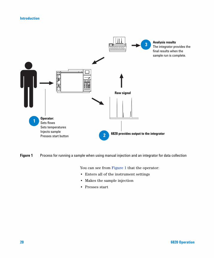
If you are using an integrator, the process for running a sample is similar to the process shown in Figure 1.
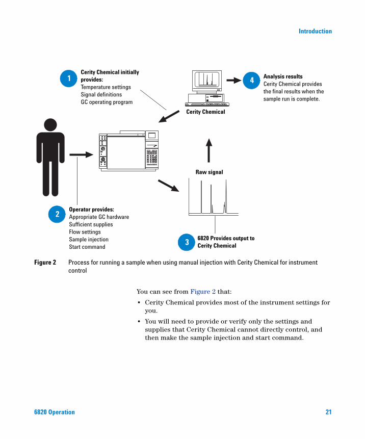
If you are using Cerity Chemical, the process for running a sample is similar to the process shown in Figure 2.
19
Introduction
Figure 1 Process for running a sample when using manual injection and an integrator for data collection
Analysis resultsThe integrator provides the final results when the sample run is complete.
Raw signal
6820 provides output to the integrator
Operator:Sets flowsSets temperaturesInjects samplePresses start button
3
2
1
20
You can see from Figure 1 that the operator:
• Enters all of the instrument settings
• Makes the sample injection
• Presses start
6820 Operation
Introduction
Figure 2 Process for running a sample when using manual injection with Cerity Chemical for instrumentcontrol
Analysis resultsCerity Chemical provides the final results when the sample run is complete.
Cerity Chemical
Raw signal
Cerity Chemical initially provides: Temperature settings Signal definitions GC operating program
6820 Provides output to Cerity Chemical
Operator provides:Appropriate GC hardwareSufficient suppliesFlow settingsSample injectionStart command
4
2
3
1
6820 Operation
You can see from Figure 2 that:
• Cerity Chemical provides most of the instrument settings for you.
• You will need to provide or verify only the settings and supplies that Cerity Chemical cannot directly control, and then make the sample injection and start command.
21
Introduction
Important Safety Warnings
22
Before moving on, there are several important safety notices that you should always keep in mind when using the 6820 GC.
Many internal parts of the GC carry dangerous voltages
If the GC is connected to a power source, even if the power switch is off, potentially dangerous voltages exist on:
• The wiring between the GC power cord and the AC power supply, the AC power supply itself, and the wiring from the AC power supply to the power switch.
With the power switch on, potentially dangerous voltages also exist on:
• All electronics boards in the instrument.
• The internal wires and cables connected to these boards.
• The wires for any heater (oven, detector, inlet, or valve box).
All these parts are shielded by covers. With the covers in place, it
WARNINGshould be difficult to accidentally make contact with dangerous voltages. Unless specifically instructed to, never remove a cover unless the detector, inlet, or oven are turned off.If the power cord insulation is frayed or worn, the cord must be
Electrostatic discharge is a threat to GC electronics
WARNINGreplaced. Contact your Agilent service representative.
The printed circuit (PC) boards in the GC can be damaged by electrostatic discharge. Do not touch any of the boards unless it is absolutely necessary. If you must handle them, wear a grounded wrist strap and take other antistatic precautions. Wear a grounded wrist strap any time you must remove the GC right side cover.
6820 Operation
Introduction
Many parts are dangerously hot
6820 Operation
Many parts of the GC operate at temperatures high enough to cause serious burns. These parts include but are not limited to:
• The inlets
• The oven and its contents
• The detectors
• The column nuts attaching the column to an inlet or detector
• The valve box
You should always cool these areas of the GC to room temperature before working on them. They will cool faster if you first set the temperature of the heated zone to room temperature. Turn the zone off after it has reached the setpoint. If you must perform maintenance on hot parts, use a wrench and wear gloves. Whenever possible, cool the part of the instrument that you will be maintaining before you begin working on it.
Be careful when working behind the instrument. During cool-down
WARNINGcycles, the GC emits hot exhaust which can cause burns.WARNING The insulation around the inlets, detectors, valve box, and the insulation cups is made of refractory ceramic fibers. To avoid inhaling fiber particles, we recommend the following safety procedures: ventilate your work area; wear long sleeves, gloves, safety glasses, and a disposable dust/mist respirator; dispose of insulation in a sealed plastic bag; wash your hands with mild soap and cold water after handling the insulation.
23
Introduction
Hydrogen
24
Hydrogen gas may be used as carrier gas, and/or as fuel for the FID. When mixed with air, hydrogen can form explosive mixtures.
WARNING When using hydrogen (H2) as the carrier gas or fuel gas, be aware that hydrogen gas can flow into the oven and create an explosion hazard. Therefore, be sure that the supply is off until all connections are made, and ensure that the inlet and detector column fittings are either connected to a column or capped at all times when hydrogen gas is supplied to the instrument.
Hydrogen is flammable. Leaks, when confined in an enclosed space, may create a fire or explosion hazard. In any application using hydrogen, leak test all connections, lines, and valves before operating the instrument. Always turn off the hydrogen supply at its source before working on the instrument.
The GC cannot detect leaks in inlet and/or detector gas streams. For
WARNINGthis reason, it is vital that column fittings should always be either connected to a column, or have a cap or plug installed.When using hydrogen gas,check the system for leaks to prevent possible fire and explosion hazards based on local Environmental Health and Safety (EHS) requirements. Always check for leaks after changing a tank or servicing the gas lines. Always make sure the vent line is vented into a fume hood.
Electron Capture Detector (ECD)
This section describes the licensing information, handling precautions and safety requirements concerning the Electron Capture Detector (ECD).
6820 Operation
Introduction
6820 Operation
The ECD contains a cell plated with 63Ni, a radioactive isotope. 63Ni releases β particles which collide with carrier gas molecules to produce low-energy electrons — each β particle produces approximately 100 electrons. The free electrons produce a small current — called the reference or standing current — which is collected and measured.
The 63Ni isotope
The radioactive isotope used in the cell is 63Ni. It is plated onto the inner surface of the cell body and is solid at temperatures used in chromatography. Some other properties are listed in Table 1.
ECD licenses
Customers in China can purchase an ECD under either a General License or a Specific License. Customers outside China should contact their local Agilent sales office for information.
The license details below reflect China’s regulations.
Specific license Specific license ECDs require you to obtain a Materials License from the Health Bureau or local state agency, permitting you to possess the amount and kind of radioisotope used in the detector. You can typically ship, sell, or transfer the ECD to other Specific Licensees. If the license permits, you may also open the ECD for cleaning.
Table 1 Properties of 63Ni
Half-life: 101.1 years
Emission: 65.87 keV max., beta radiation
Melting point: 1453 °C
Dimensions of the active partof the ECD:
Inside diameter: 6 mmHeight: 4.2 mm
Total activity (ECD cell): 555 MBq (15 millicuries) maximum
25
26
Introduction
General license General license ECDs do not require a materials license. You become a General Licensee automatically when you purchase a ECD directly from Agilent Technologies. Some states may require that you register the ECD with a state agency.
Certain restrictions apply to General Licenses:
• Owners may not open the ECD cell.
• Owners shall not modify the cell in any manner.
• Owners shall not use any solvent, including water, to internally clean the cell.
• Owners shall not interfere with or attempt to defeat the overheat circuitry that may be supplied with the ECD.
• Owners shall not transfer the ECD to another person or another location except as described in the applicable Regulations.
• Owners must perform a radioactive leak test at least every 6 months or as required by your local Agency.
• Owners must maintain records as required by your local Agency (the Health Bureau or, in certain states, a state agency).
• Owners must notify the Agency in case of incidents or failures that might lead to a hazardous condition.
Additional information is available in the publication “Information for General Licensees,” part no. 5961-5664.
ECD warnings
Although beta particles at this energy level have little penetrating power — the surface layer of the skin or a few sheets of paper will stop most of them — they may be hazardous if the isotope is ingested or inhaled. For this reason the cell must be handled with care: radioactive leak tests must be performed at the required intervals, the inlet and outlet fittings must be capped when the detector is not in use, corrosive chemicals must not be introduced into the detector, and the effluent from the detector must be vented outside the laboratory environment.
6820 Operation
Introduction
6820 Operation
Materials that may react with the 63Ni source, either to form volatile
WARNINGproducts or to cause physical degradation of the plated film, must be avoided. These materials include oxidizing compounds, acids, wet halogens, wet nitric acid, ammonium hydroxide, hydrogen sulfide, PCBs, and carbon monoxide. This list is not exhaustive but indicates the kinds of compounds that may cause damage to 63Ni detectors.In the extremely unlikely event that both the oven and the detector heated zone should go into thermal runaway (maximum, uncontrolled heating in excess of 400 °C) at the same time, and that the detector remains exposed to this condition for more than 12 hours, take the following steps:
1 After turning off the main power and allowing the instrument to cool, cap the detector inlet and exhaust vent openings. Wear disposable plastic gloves and observe normal laboratory safety precautions.
2 Return the cell for exchange. Contact your local Agilent sales office for details. Include a letter stating the condition of abuse.
It is unlikely, even in this very unusual situation, that radioactive material will escape the cell. However, permanent damage to the 63Ni plating within the cell is possible, and therefore, the cell must be returned for exchange.
Do not use solvents to clean the ECD.
WARNINGYou may not open the ECD cell unless authorized to do so by your local nuclear regulatory agency. Do not disturb the four socket-head bolts. These hold the cell halves together. Removing or disturbing them is a violation of the terms of the General License and could create a safety hazard.27
28
Introduction
Safety precautions when handling ECDs
Always observe the following precautions:
• Never eat, drink, or smoke when handling ECDs.
• Always wear safety glasses when working with or near open ECDs.
• Wear protective clothing such as laboratory jackets, safety glasses, and gloves, and follow good laboratory practices. Wash hands thoroughly with a mild non-abrasive cleaner after handling ECDs.
• Cap the inlet and outlet fittings when the ECD is not in use.
• Connect the ECD exhaust vent to a fume hood or vent it to the outside.
Agilent Technologies recommends a vent line inside diameter of 6 mm (1/4-inch) or greater. With a line of this diameter, the length is not critical.
6820 Operation
Introduction
Safety and Regulatory Certifications
6820 Operation
The 6820 GC conforms to the following safety standards:
• Canadian Standards Association (CSA): C22.2 No. 1010.1
• CSA/Nationally Recognized Test Laboratory (NRTL): UL 61010A–1
• International Electrotechnical Commission (IEC): 61010–1
• EuroNorm (EN): 61010–1
The 6820 GC conforms to the following regulations on Electromagnetic Compatibility (EMC) and Radio Frequency Interference (RFI):
• CISPR 11/EN 55011: Group 1, Class A
• IEC/EN 61326
• AUS/NZ
This ISM device complies with Canadian ICES-001. Cet appareil ISM est conforme a la norme NMB—001 du Canada.
The 6820 GC is designed and manufactured under a quality system registered to ISO 9001.
Information
The Agilent Technologies 6820 Gas Chromatograph meets the following IEC (International Electro-technical Commission) classifications: Safety Class I, Transient Overvoltage Category II, Pollution Degree 2.
This unit has been designed and tested in accordance with recognized safety standards and is designed for use indoors. If the instrument is used in a manner not specified by the manufacturer, the protection provided by the instrument may be impaired. Whenever the safety protection of the 6820 Gas Chromatograph has been compromised, disconnect the unit from all power sources and secure the unit against unintended operation.
29
30
Introduction
Refer servicing to qualified service personnel. Substituting parts or performing any unauthorized modification to the instrument may result in a safety hazard.
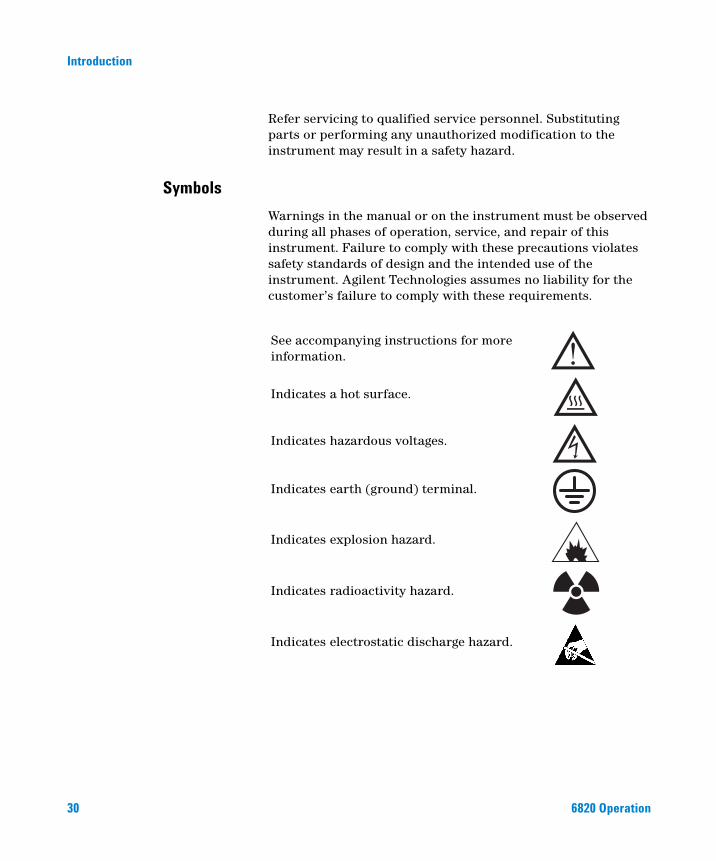
Symbols
Warnings in the manual or on the instrument must be observed during all phases of operation, service, and repair of this instrument. Failure to comply with these precautions violates safety standards of design and the intended use of the instrument. Agilent Technologies assumes no liability for the customer’s failure to comply with these requirements.
See accompanying instructions for more information.
Indicates a hot surface.
Indicates hazardous voltages.
Indicates earth (ground) terminal.
Indicates explosion hazard.
Indicates radioactivity hazard.
Indicates electrostatic discharge hazard.
6820 Operation
Introduction
Electromagnetic compatibility
6820 Operation
This device complies with the requirements of CISPR 11. Operation is subject to the following two conditions:
• This device may not cause harmful interference.
• This device must accept any interference received, including interference that may cause undesired operation.
If this equipment does cause harmful interference to radio or television reception, which can be determined by turning the equipment off and on, the user is encouraged to try one or more of the following measures:
1 Relocate the radio or antenna.
2 Move the device away from the radio or television.
3 Plug the device into a different electrical outlet, so that the device and the radio or television are on separate electrical circuits.
4 Make sure that all peripheral devices are also certified.
5 Make sure that appropriate cables are used to connect the device to peripheral equipment.
6 Consult your equipment dealer, Agilent Technologies, or an experienced technician for assistance.
7 Changes or modifications not expressly approved by Agilent Technologies could void the user’s authority to operate the equipment.
Sound Emission Certification for Federal Republic of Germany
Sound pressure
Sound pressure Lp < 65 dB(A) according to DIN-EN 27779.
Schalldruckpegel
Schalldruckpegel LP < 65 dB(A) nach DIN-EN 27779.
31
Introduction
Cleaning
32
To clean the unit, disconnect the power and wipe down with a damp, lint-free cloth.
Recycling the Product
For recycling, contact your local Agilent sales office.
6820 Operation
Agilent 6820 Gas ChromatographOperation
2Strategy for Using the 6820
Overview 34
Storable experiment settings 34
Nonstorable experiment settings 35
Stored configuration settings 35
What is the difference between a 6820 method and a Cerity Chemical method for the 6820? 35
Operating Strategy 36
Related Topics
Chapter 6, “Running Samples”Chapter 8, “Developing Methods”
This section describes a helpful strategy for using the 6820 as a standalone instrument that outputs signal data to some device, such as an Agilent 3396C integrator. It also describes the types of settings the instrument stores and recalls.
33Agilent Technologies
Strategy for Using the 6820
Overview
34
This overview explains how some of the features of the 6820 interact during use, and provides simplified procedures that can be adapted for your application.
Storable experiment settings
The 6820 uses electronic control to automate many of the instrument control functions. These settings can be entered using the keypad and display before each run, or they can be stored and recalled for use when needed. Storing the settings is the easiest way to consistently prepare the GC for a run. This collection of settings is called a “method.” The 6820 can store nine methods, each consisting of the following:
• Oven run-time temperature profile (including temperature ramps)
• Front/Back inlet temperature settings
• Front/Back detector temperature settings
• Signal settings
• Heated valve box (and similar device) control settings and temperature profile
• Valve run-time settings and configuration data (type, sample loop size, etc.)
• Run-time events
All of these settings are explained in detail in later sections of this manual.
NOTE The operating procedures presented here assume the use of stored methods when preparing for a sample run.
6820 Operation
Strategy for Using the 6820
Nonstorable experiment settings
6820 Operation
The following settings are not storable in methods:
• Flow/Pressure settings. Gas flows are manually controlled.
• Clock table events. The clock table is not storable. For information on the clock table, “Programming the Clock Table” on page 144.
Stored configuration settings
In addition to the information stored in the method, the GC also stores its current hardware configuration outside of any method. Examples of this type of information are:
• Time and date
• RS-232 communications settings
• IP address
• Hardware configuration settings, such as: auxiliary heated zone types, valve types, gas sampling valve loop sizes, inlet types, detector types, etc.
• Oven equilibration and maximum temperature
For information on how to set these parameters, see “Configure the Instrument” on page 72.
What is the difference between a 6820 method and a Cerity Chemical method for the 6820?
Agilent data systems, such as Agilent Cerity Networked Data System for Chemical QA/QC, also store methods. A Cerity Chemical method contains every setting that a 6820 method does, but it can also include complete information for data analysis and reporting (for example, integration events and parameters, calibration data, signal output options, and reporting options). While both types of method control the instrument and produce signal output, only the Cerity Chemical method analyzes the data to integrate, identify, and report the peaks discovered.
35
Strategy for Using the 6820
Operating Strategy
36
Use the following strategy for successful operation. Usually, step 1 is performed by the chemist who develops the analysis technique. Steps 2 through 4 are performed by whoever runs the sample.
“Creating Methods” on page 150 gives an overview of the method creation process.
Chapter 6, “Running Samples,” lists the basic procedures for operating the GC.
For more information about method creation and related topics, see Chapter 8, “Developing Methods.”
Operating strategy
Step Notes
1 Create the 6820 analytical method. See “Creating Methods” on page 150.
2 Prepare the GC to run samples. See “Prepare the GC to Run Samples” on page 135.
3 Set the GC operating conditions, including flow rates for carrier and detector gases and temperatures.
Typically, this is done by:a Loading a stored collection of
settings and instructions called a “method,” then
b Manually setting gas flows
Alternately, enter settings and instructions manually before each run.
See “Run a Sample Using Manual Injection” on page 136 and “Run a Sample Using Manual Injection” on page 136.
4 Perform the injection.
5 Collect the data. Performed by the integrator or data system.
6820 Operation

Agilent 6820 Gas ChromatographOperation
3Controls and Components
GC Control and Component Locations 38
Keyboard and Display 40
The Display 41
Status Indicators 46
The Keyboard 47
Instant action keys [Start], [Stop], and [Prep Run] 48
Function keys 48
Short-cut keys: [Temp] and [Ramp#] 49
Information keys 51
Miscellaneous keys 54
Modifier keys 61
Storage 63
How to Make a Setting 68
This section shows you where the controls are located on the 6820, and then describes how to use the electronic controls to perform a few common tasks. Chapter 5, “Setting Flows”, describes how to set gas flow rates.
37Agilent Technologies
Controls and Components
GC Control and Component Locations
38
There are two types of controls on the 6820: electronic controls and flow controls. The electronic controls are used for tasks such as turning the instrument on, making program settings, and starting or stopping a run. The flow controls set the gas flows.
Figure 3 shows the locations of the general GC components, controls, and switches. It also points out the location of other GC parts that you will use frequently.
Figure 3 Location of 6820 controls and components
Display
Keyboard
On/Off switch
Detector cover
Flow controls
Column oven door
Run status display
Oven door latch
Front inlet
Back inlet
Front detector
Back detector
Top view, detector cover removed
Front view
6820 Operation
Controls and Components
6820 Operation
• To open the detector cover, lift it. It tilts up.
• To open the oven, lift the oven door latch at the bottom right of the oven door.
39
Controls and Components
Keyboard and Display
40
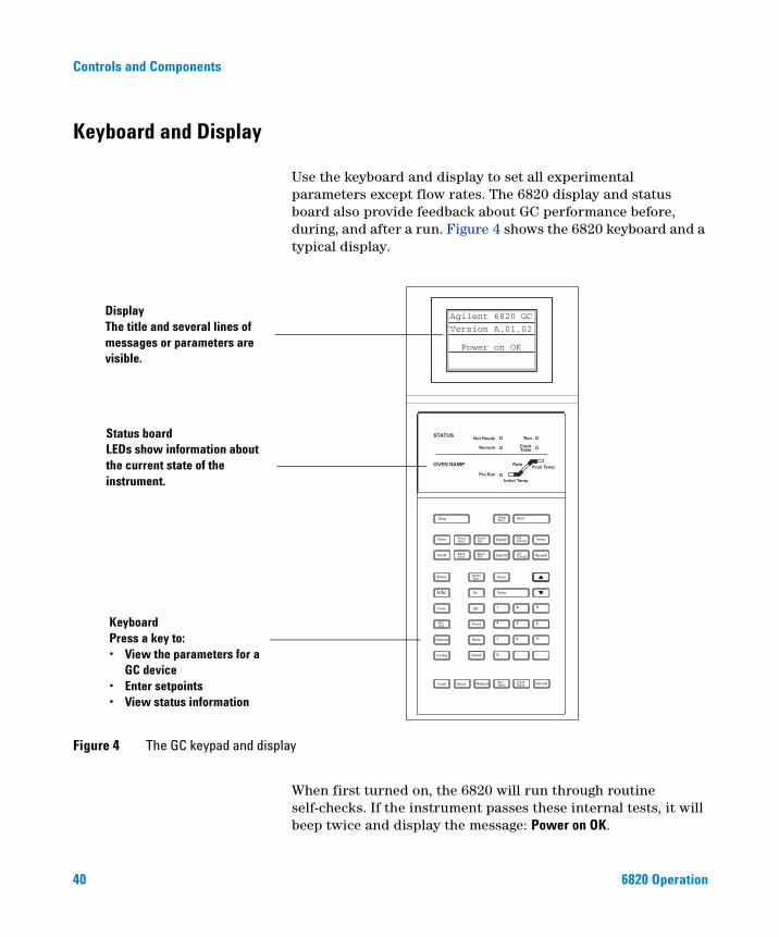
Use the keyboard and display to set all experimental parameters except flow rates. The 6820 display and status board also provide feedback about GC performance before, during, and after a run. Figure 4 shows the 6820 keyboard and a typical display.
Figure 4 The GC keypad and display
Agilent 6820 GC
Version A.01.02
Power on OK
DisplayThe title and several lines of messages or parameters are visible.
Status boardLEDs show information about the current state of the instrument.
KeyboardPress a key to:• View the parameters for a
GC device• Enter setpoints• View status information
When first turned on, the 6820 will run through routine self-checks. If the instrument passes these internal tests, it will beep twice and display the message: Power on OK.
6820 Operation
Controls and Components
The Display
6820 Operation
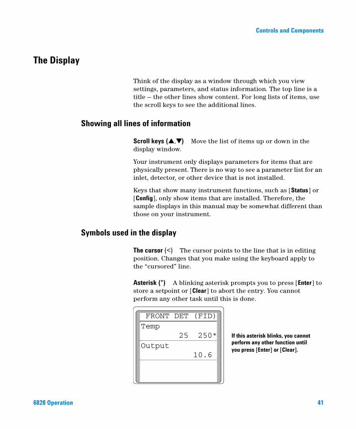
Think of the display as a window through which you view settings, parameters, and status information. The top line is a title — the other lines show content. For long lists of items, use the scroll keys to see the additional lines.
Showing all lines of information
Scroll keys (▲,▼) Move the list of items up or down in the display window.
Your instrument only displays parameters for items that are physically present. There is no way to see a parameter list for an inlet, detector, or other device that is not installed.
Keys that show many instrument functions, such as [Status] or [Config], only show items that are installed. Therefore, the sample displays in this manual may be somewhat different than those on your instrument.
Symbols used in the display
The cursor (<) The cursor points to the line that is in editing position. Changes that you make using the keyboard apply to the “cursored” line.
Asterisk (*) A blinking asterisk prompts you to press [Enter] to store a setpoint or [Clear] to abort the entry. You cannot perform any other task until this is done.
If this asterisk blinks, you cannot perform any other function untilyou press [Enter] or [Clear].
FRONT DET (FID)Temp 25 250*Output 10.6
41
42
Controls and Components
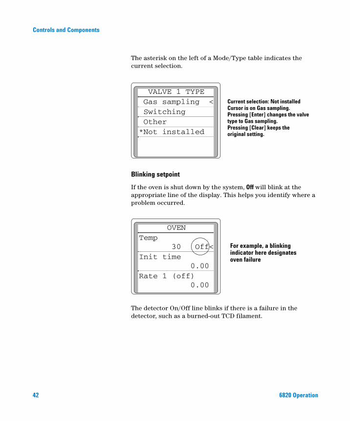
The asterisk on the left of a Mode/Type table indicates the current selection.
Blinking setpoint
If the oven is shut down by the system, Off will blink at the appropriate line of the display. This helps you identify where a problem occurred.
The detector On/Off line blinks if there is a failure in the detector, such as a burned-out TCD filament.
Current selection: Not installedCursor is on Gas sampling.Pressing [Enter] changes the valvetype to Gas sampling. Pressing [Clear] keeps the original setting.
VALVE 1 TYPE Gas sampling < Switching Other*Not installed
OVEN Temp
30 Off<Init time
0.00 Rate 1 (off)
0.00
For example, a blinking indicator here designatesoven failure
6820 Operation

Controls and Components
6820 Operation
Actual and setpoint values
When there are two values in one line of the display, the left value is always actual and the right value is always a setpoint. When there is only one value, it is either an actual or setpoint, depending on the parameter.
Actual valueSetpoint value
Actual value
FRONT DET (FID)Temp 25 250*Output 10.6
Sounds used with the display
Beeping instrument Any type of fault, warning, or shutdown is accompanied by one beep.
43
Controls and Components
Messages
44
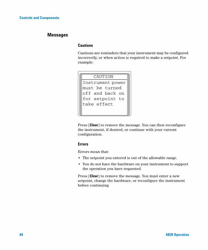
Cautions
Cautions are reminders that your instrument may be configured incorrectly, or when action is required to make a setpoint. For example:
Press [Clear] to remove the message. You can then reconfigure the instrument, if desired, or continue with your current configuration.
Errors
Errors mean that:
• The setpoint you entered is out of the allowable range.
• You do not have the hardware on your instrument to support the operation you have requested.
Press [Clear] to remove the message. You must enter a new setpoint, change the hardware, or reconfigure the instrument before continuing.
CAUTION Instrument power must be turned off and back on for setpoint to take effect
6820 Operation
Controls and Components
6820 Operation
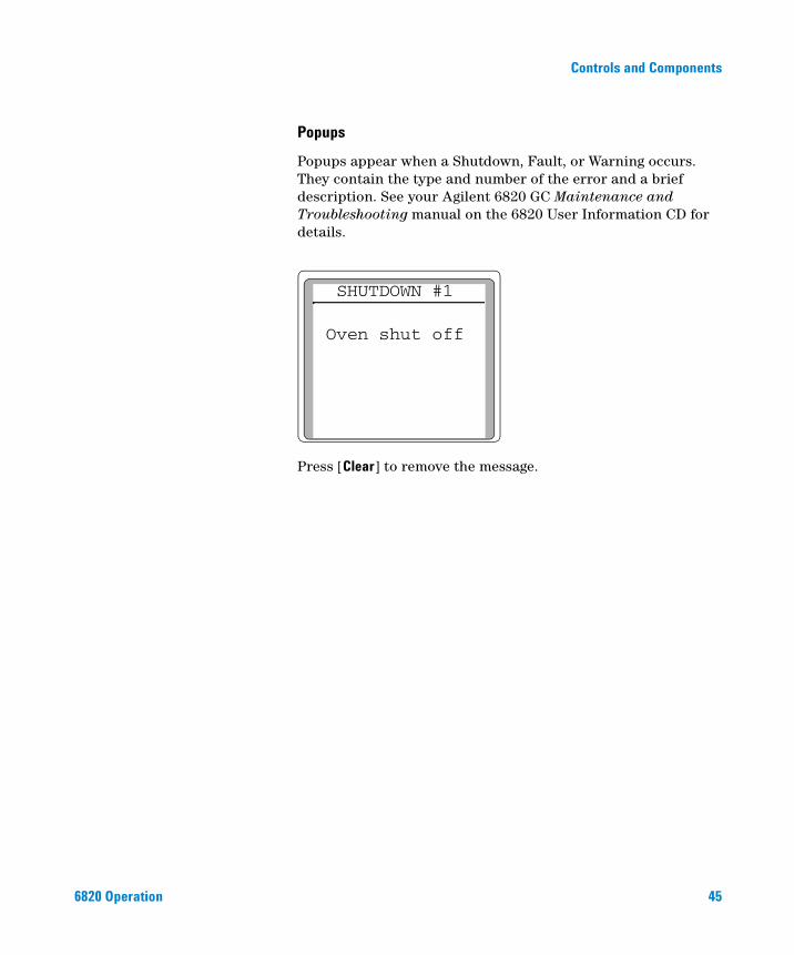
Popups
Popups appear when a Shutdown, Fault, or Warning occurs. They contain the type and number of the error and a brief description. See your Agilent 6820 GC Maintenance and Troubleshooting manual on the 6820 User Information CD for details.
Press [Clear] to remove the message.
SHUTDOWN #1
Oven shut off
45
Controls and Components
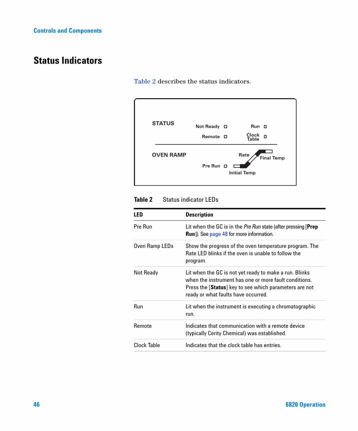
Status Indicators
46
Table 2 describes the status indicators.
Table 2 Status indicator LEDs
LED Description
Pre Run Lit when the GC is in the Pre Run state (after pressing [Prep Run]). See page 48 for more information.
Oven Ramp LEDs Show the progress of the oven temperature program. The Rate LED blinks if the oven is unable to follow the program.
Not Ready Lit when the GC is not yet ready to make a run. Blinks when the instrument has one or more fault conditions. Press the [Status] key to see which parameters are not ready or what faults have occurred.
Run Lit when the instrument is executing a chromatographic run.
Remote Indicates that communication with a remote device (typically Cerity Chemical) was established.
Clock Table Indicates that the clock table has entries.
6820 Operation
Controls and Components
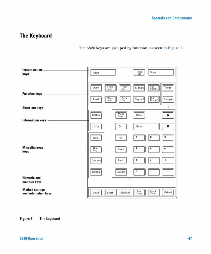
The Keyboard
6820 Operation
The 6820 keys are grouped by function, as seen in Figure 5.
Figure 5 The keyboard
Instant action
Function keys
Short-cut keys
Information keys
Numeric andmodifier keys
Miscellaneous
Method storageand automation keys
keys
keys
47
Controls and Components
Instant action keys [Start], [Stop], and [Prep Run]
48
These keys trigger the instrument to do something immediately.
[Start] and [Stop]
Start and stop any type of run. [Stop] also cancels a Prep Run or power fail recovery.
[Prep Run]
Prepares the GC for a run when using splitless injection. If you are using splitless injection, press [Prep Run] to close the purge valve before injecting the sample.
Pressing [Prep Run] turns on the Pre Run LED. This LED blinks while the instrument prepares for a run and is waiting to reach instrument setpoints (other than the ones associated with Pre Run). Once these setpoints are ready, the LED remains on and the purge valve switches to the inject position. After a short (6-second) equilibration time, the instrument becomes ready for a run and the Not Ready light goes out.
If you press [Prep Run] while the Pre Run LED is blinking, the purge valve immediately switches to the inject position before all the other setpoints are ready. The Pre Run LED remains on.
Function keys
Summary Table 3 lists the function keys, a brief description of their use, and where to find detailed information.
6820 Operation
Controls and Components
6820 Operation
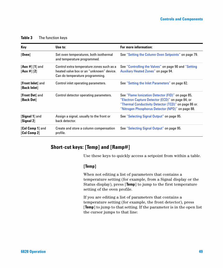
Short-cut keys: [Temp] and [Ramp#]
Table 3 The function keys
Key Use to: For more information:
[Oven] Set oven temperatures, both isothermal and temperature programmed.
See “Setting the Column Oven Setpoints” on page 79.
[Aux #] [1] and [Aux #] [2]
Control extra temperature zones such as a heated valve box or an “unknown” device. Can do temperature programming.
See “Controlling the Valves” on page 90 and “Setting Auxiliary Heated Zones” on page 94.
[Front Inlet] and [Back Inlet]
Control inlet operating parameters. See “Setting the Inlet Parameters” on page 82.
[Front Det] and [Back Det]
Control detector operating parameters. See “Flame Ionization Detector (FID)” on page 85, “Electron Capture Detector (ECD)” on page 84, or “Thermal Conductivity Detector (TCD)” on page 86 or.“Nitrogen Phosphorus Detector (NPD)” on page 88.
[Signal 1] and [Signal 2]
Assign a signal, usually to the front or back detector.
See “Selecting Signal Output” on page 95.
[Col Comp 1] and [Col Comp 2]
Create and store a column compensation profile.
See “Selecting Signal Output” on page 95.
Use these keys to quickly access a setpoint from within a table.
[Temp]
When not editing a list of parameters that contains a temperature setting (for example, from a Signal display or the Status display), press [Temp] to jump to the first temperature setting of the oven profile.
If you are editing a list of parameters that contains a temperature setting (for example, the front detector), press [Temp] to jump to that setting. If the parameter is in the open list the cursor jumps to that line:
49
50
Controls and Components
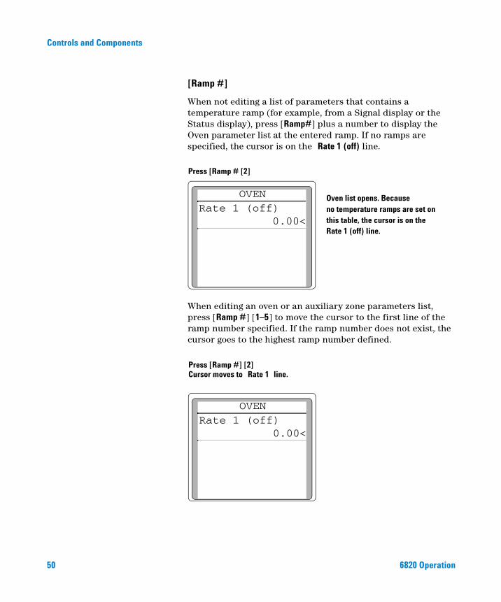
[Ramp #]
When not editing a list of parameters that contains a temperature ramp (for example, from a Signal display or the Status display), press [Ramp#] plus a number to display the Oven parameter list at the entered ramp. If no ramps are specified, the cursor is on the Rate 1 (off) line.
When editing an oven or an auxiliary zone parameters list, press [Ramp #] [1–5] to move the cursor to the first line of the ramp number specified. If the ramp number does not exist, the cursor goes to the highest ramp number defined.
Press [Ramp # [2]
Oven list opens. Becauseno temperature ramps are set on this table, the cursor is on the
OVEN Rate 1 (off) 0.00<
Rate 1 (off) line.
Press [Ramp #] [2]Cursor moves to Rate 1 line.
OVEN Rate 1 (off) 0.00<
6820 Operation
Controls and Components
Information keys
6820 Operation
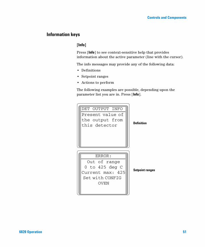
[Info]
Press [Info] to see context-sensitive help that provides information about the active parameter (line with the cursor).
The info messages may provide any of the following data:
• Definitions
• Setpoint ranges
• Actions to perform
The following examples are possible, depending upon the parameter list you are in. Press [Info].
Definition
Setpoint ranges
DET OUTPUT INFOPresent value of the output from this detector
ERROR: Out of range 0 to 425 deg CCurrent max: 425 Set with CONFIG
OVEN
51
52
Controls and Components
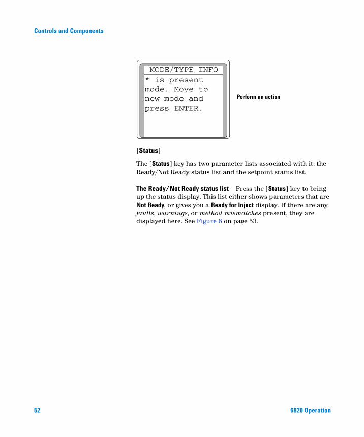
[Status]
The [Status] key has two parameter lists associated with it: the Ready/Not Ready status list and the setpoint status list.
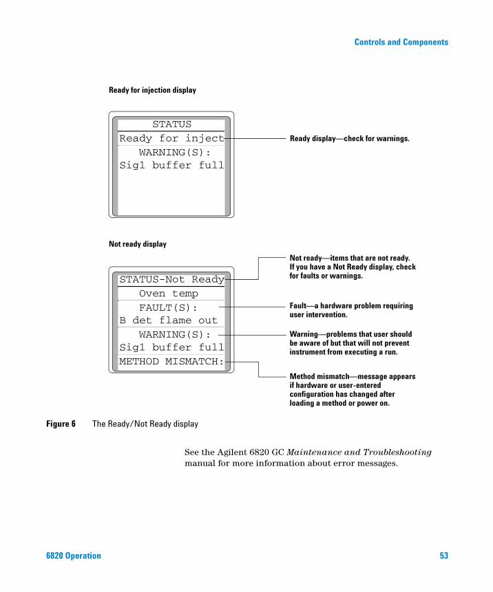
The Ready/Not Ready status list Press the [Status] key to bring up the status display. This list either shows parameters that are Not Ready, or gives you a Ready for Inject display. If there are any faults, warnings, or method mismatches present, they are displayed here. See Figure 6 on page 53.
Perform an action
MODE/TYPE INFO* is present mode. Move to new mode and press ENTER.
6820 Operation
Controls and Components
6820 Operation
Figure 6 The Ready/Not Ready display
Ready for injection display
Not ready display
Ready display—check for warnings.
Not ready—items that are not ready.If you have a Not Ready display, check for faults or warnings.
Fault—a hardware problem requiring user intervention.
Warning—problems that user shouldbe aware of but that will not preventinstrument from executing a run.
Method mismatch—message appears
configuration has changed after loading a method or power on.
if hardware or user-entered
STATUS-Not Ready Oven temp FAULT(S):B det flame out WARNING(S):Sig1 buffer fullMETHOD MISMATCH:
STATUSReady for inject WARNING(S):Sig1 buffer full
See the Agilent 6820 GC Maintenance and Troubleshooting manual for more information about error messages.
53
54
Controls and Components
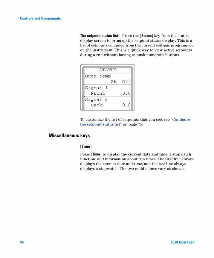
The setpoint status list Press the [Status] key from the status display screen to bring up the setpoint status display. This is a list of setpoints compiled from the current settings programmed on the instrument. This is a quick way to view active setpoints during a run without having to push numerous buttons.
To customize the list of setpoints that you see, see “Configure the setpoint status list” on page 75.
STATUSOven temp 26 OffSignal 1 Front 0.0Signal 2 Back 0.0
Miscellaneous keys
[Time]
Press [Time] to display the current date and time, a stopwatch function, and information about run times. The first line always displays the current date and time, and the last line always displays a stopwatch. The two middle lines vary as shown.
6820 Operation
Controls and Components
6820 Operation
Time display between runs
Time display during a run
Actual time and date
Static display of last and
Stopwatch
Counts time elapsed during run
Counts down time remaining in run
next runtime in minutes
9:30 10 Jun 03Last runtime 18.05<Next runtime 80.00 time = 0:00.0 1/t = 0.00
9:31 10 Jun 03Elapsed time 18.05 Time left 71.95
55
56
Controls and Components
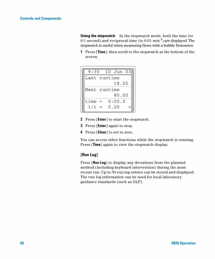
Using the stopwatch In the stopwatch mode, both the time (to 0.1 second) and reciprocal time (to 0.01 min-1) are displayed. The stopwatch is useful when measuring flows with a bubble flowmeter.
1 Press [Time], then scroll to the stopwatch at the bottom of the screen.
2 Press [Enter] to start the stopwatch.
3 Press [Enter] again to stop.
4 Press [Clear] to set to zero.
You can access other functions while the stopwatch is running. Press [Time] again to view the stopwatch display.
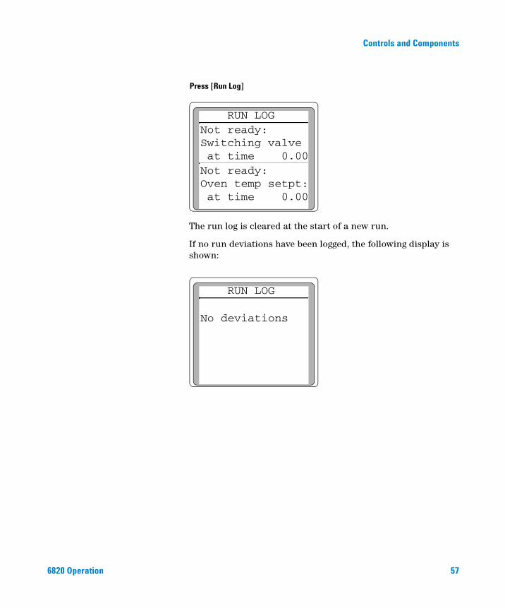
[Run Log]
Press [Run Log] to display any deviations from the planned method (including keyboard intervention) during the most recent run. Up to 50 run log entries can be stored and displayed. The run log information can be used for local laboratory guidance standards (such as GLP).
9:30 10 Jun 03Last runtime 18.05 Next runtime 80.00 time = 0:00.0 1/t = 0.00 <
6820 Operation
Controls and Components
6820 Operation
The run log is cleared at the start of a new run.
If no run deviations have been logged, the following display is shown:
Press [Run Log]
RUN LOGNot ready:Switching valve at time 0.00Not ready:Oven temp setpt: at time 0.00
RUN LOG
No deviations
57
58
Controls and Components
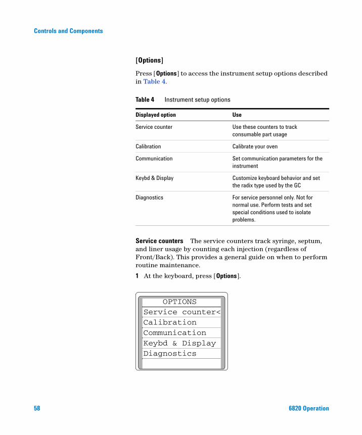
[Options]
Press [Options] to access the instrument setup options described in Table 4.
Service counters The service counters track syringe, septum, and liner usage by counting each injection (regardless of Front/Back). This provides a general guide on when to perform routine maintenance.
1 At the keyboard, press [Options].
Table 4 Instrument setup options
Displayed option Use
Service counter Use these counters to track consumable part usage
Calibration Calibrate your oven
Communication Set communication parameters for the instrument
Keybd & Display Customize keyboard behavior and set the radix type used by the GC
Diagnostics For service personnel only. Not for normal use. Perform tests and set special conditions used to isolate problems.
OPTIONSService counter<CalibrationCommunicationKeybd & DisplayDiagnostics
6820 Operation
Controls and Components
6820 Operation
2 Scroll to Service counter. Press [Enter].
3 Scroll to the desired counter and press [Clear].
4 Press [Enter] to set the counter to 0 or [Clear] to cancel.
Calibration Lists the parameters that can be calibrated. The calibration displays are discussed in the Agilent 6820 Service manual on the 6820 User Information CD.
Communication Allows access to the communications setpoint parameters. The communication displays are discussed in “Configure your RS-232 communications settings” on page 76 and in “Configure your LAN communications” on page 77.
Diagnostics The diagnostic parameters are for use by your Service Representative. Diagnostics are discussed in the Agilent 6820 Service manual on the 6820 User Information CD.
Keybd & Display Use these options to set the keyboard’s behavior.
• Keyboard lock—disables keyboard setpoint changes. The keyboard will still function but no setpoints can be altered while keyboard lock is enabled. The [Start], [Stop], [Prep Run], [Load], and [Method] keys will all function normally when keyboard lock is activated.
• Key click—click sound when keys are pressed, can be turned on or off.
• Warning beep—allows you to hear warning beeps.
• Method mod beep—turn ON for high pitched beep when method setpoint is modified.
• Radix type—allows you to choose between a period (.) or comma (,).
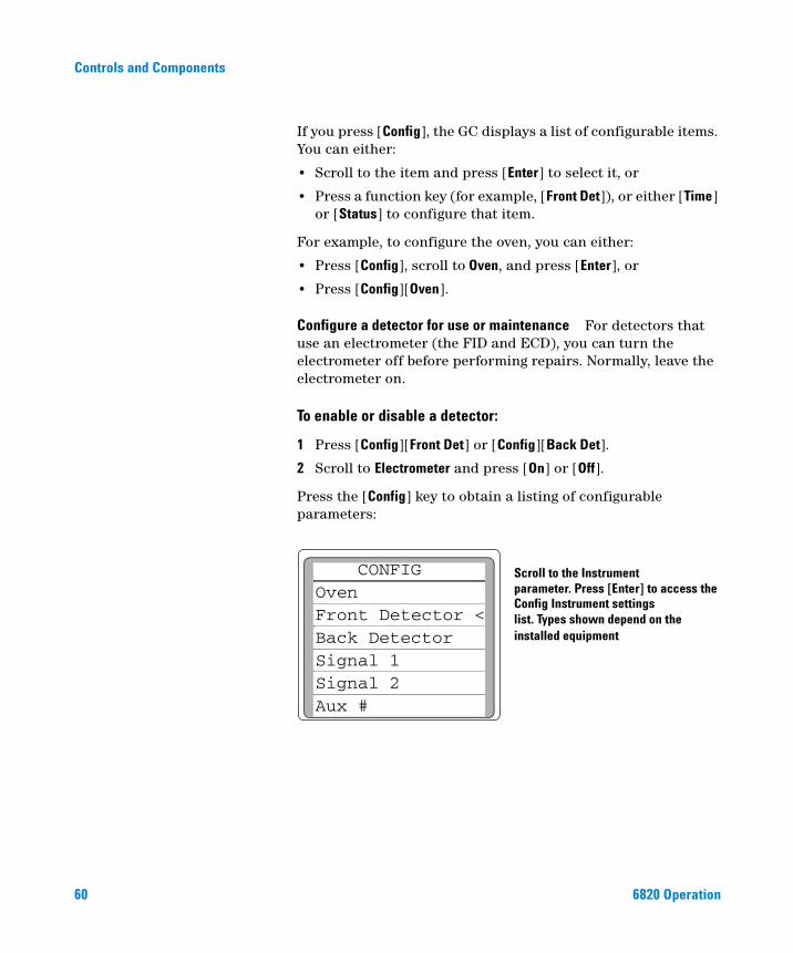
[Config]
Press [Config] to set up configurations for instrument control. Most configuration settings either do not change frequently or apply to every run. Some examples are: date and time, maximum oven temperature, inlet type, and gas sampling valve loop size.
59
60
Controls and Components
If you press [Config], the GC displays a list of configurable items. You can either:
• Scroll to the item and press [Enter] to select it, or
• Press a function key (for example, [Front Det]), or either [Time] or [Status] to configure that item.
For example, to configure the oven, you can either:
• Press [Config], scroll to Oven, and press [Enter], or
• Press [Config][Oven].
Configure a detector for use or maintenance For detectors that use an electrometer (the FID and ECD), you can turn the electrometer off before performing repairs. Normally, leave the electrometer on.
To enable or disable a detector:
1 Press [Config][Front Det] or [Config][Back Det].
2 Scroll to Electrometer and press [On] or [Off].
Press the [Config] key to obtain a listing of configurable parameters:
Scroll to the Instrumentparameter. Press [Enter] to access theConfig Instrument settingslist. Types shown depend on theinstalled equipment
CONFIGOven Front Detector <Back DetectorSignal 1Signal 2Aux #
6820 Operation
Controls and Components
Modifier keys
6820 Operation
Modifier keys extend the functions of some setpoint control keys.
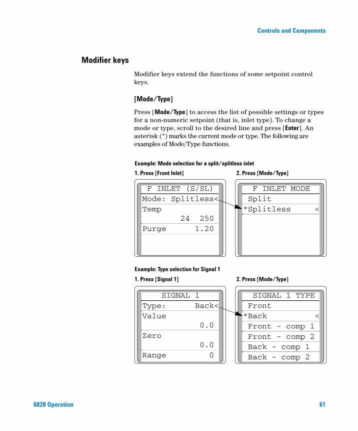
[Mode/Type]
Press [Mode/Type] to access the list of possible settings or types for a non-numeric setpoint (that is, inlet type). To change a mode or type, scroll to the desired line and press [Enter]. An asterisk (*) marks the current mode or type. The following are examples of Mode/Type functions.
2. Press [Mode/Type]
2. Press [Mode/Type]
F INLET (S/SL)Mode: Splitless<Temp 24 250 Purge 1.20
F INLET MODE Split*Splitless <
SIGNAL 1Type: Back<Value 0.0 Zero 0.0 Range 0
SIGNAL 1 TYPE Front*Back < Front - comp 1 Front - comp 2 Back - comp 1 Back - comp 2
1. Press [Front Inlet]
1. Press [Signal 1]
Example: Type selection for Signal 1
Example: Mode selection for a split/splitless inlet
61
62
Controls and Components
[Clear]
Press [Clear] to:
• Clear mis-entered setpoints (only available before pressing [Enter], while the * is still flashing).
• Back out of the Mode/Type selection list before pressing [Enter].
• Return to an upper level in nested parameter lists (such as Config or Option lists).
• Clear the stopwatch to zero.
• Clear an Info message and return to the previous display.
• Clear error messages (popup messages, errors on setpoint entries, etc.).
• Cancel a function during a method, clock table, or run table and loading or storing methods.
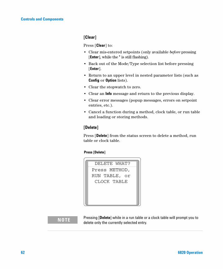
[Delete]
Press [Delete] from the status screen to delete a method, run table or clock table.
Press [Delete]
DELETE WHAT? Press METHOD, RUN TABLE, or CLOCK TABLE
Pressing [Delete] while in a run table or a clock table will prompt you to
NOTEdelete only the currently selected entry.6820 Operation
Controls and Components
6820 Operation
[.]
The radix is a decimal place holder. This parameter can be changed from the decimal point to the comma (see “Configure the radix type” on page 73).
[–]
The dash key is used to denote ranges of numbers (inclusive). For example, to denote 1 through 3, press [1] [–] [3].
This key is also used as a minus sign for negative values. For example, to enter –5, press [–] [5].
Storage
Table 5 lists the storage keys, a brief description of their use, and a place to find detailed information.
Table 5 Method storage keys
Key Use to: For more information:
[Load] Load a stored method page 65
[Store] Store up to nine methods. Stored methods are labeled and dated.
page 64
[Method] Review a list of stored methods. You can load, store, delete, or set default method.
page 64
[Run Table] View a table of events and the run time at which they occur.
page 153
[Clock Table] Display the clock time table of events in the order that they occur based on a 24-hour clock.
page 144
[Valve#] Turn valves 1 to 4 on or off. For gas sampling valves, this also starts the run.
page 90
63
64
Controls and Components
The method keys: [Load], [Store], and [Method]
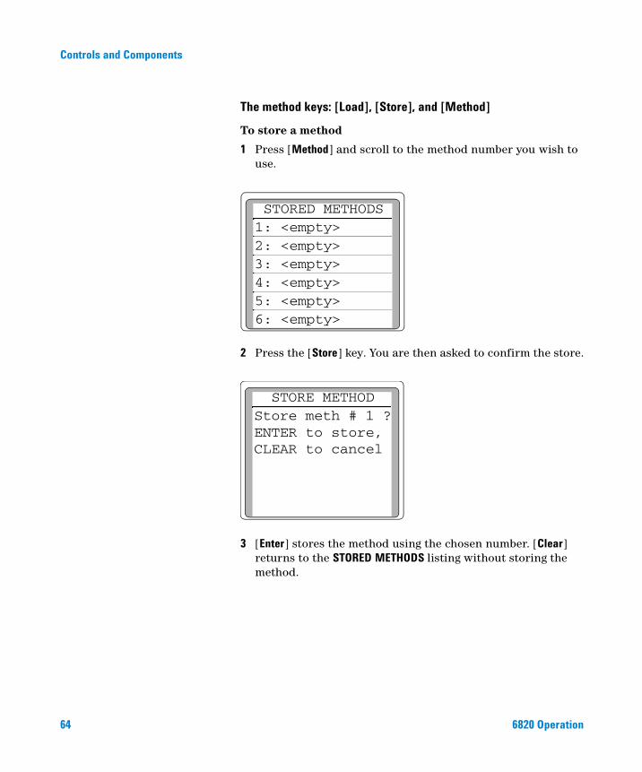
To store a method
1 Press [Method] and scroll to the method number you wish to use.
2 Press the [Store] key. You are then asked to confirm the store.
3 [Enter] stores the method using the chosen number. [Clear] returns to the STORED METHODS listing without storing the method.
STORED METHODS1: <empty>2: <empty>3: <empty>4: <empty>5: <empty>6: <empty>
STORE METHODStore meth # 1 ?ENTER to store, CLEAR to cancel
6820 Operation
Controls and Components
6820 Operation
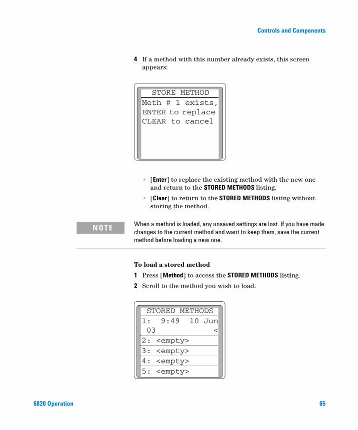
4 If a method with this number already exists, this screen appears:
• [Enter] to replace the existing method with the new one and return to the STORED METHODS listing.
• [Clear] to return to the STORED METHODS listing without storing the method.
STORE METHODMeth # 1 exists,ENTER to replace CLEAR to cancel
When a method is loaded, any unsaved settings are lost. If you have made
NOTEchanges to the current method and want to keep them, save the current method before loading a new one.To load a stored method
1 Press [Method] to access the STORED METHODS listing.
2 Scroll to the method you wish to load.
STORED METHODS1: 9:49 10 Jun 03 <2: <empty>3: <empty>4: <empty>5: <empty>
65
66
Controls and Components
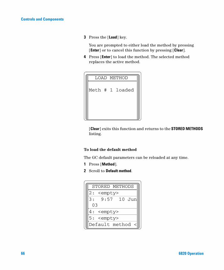
3 Press the [Load] key.
You are prompted to either load the method by pressing [Enter] or to cancel this function by pressing [Clear].
4 Press [Enter] to load the method. The selected method replaces the active method.
[Clear] exits this function and returns to the STORED METHODS listing.
To load the default method
The GC default parameters can be reloaded at any time.
1 Press [Method].
2 Scroll to Default method.
LOAD METHOD
Meth # 1 loaded
STORED METHODS2: <empty>3: 9:57 10 Jun 03 4: <empty>5: <empty>Default method <
6820 Operation
Controls and Components
6820 Operation
3 Press [Enter].
4 Press [Enter] when prompted to load the default method.
To modify a previously stored method
When a method is loaded it replaces the active method. You can modify a previously stored method by:
1 Loading the desired method
2 Making the appropriate changes
3 Storing this method under the same method number (overwrite the original method) or store as a different method number
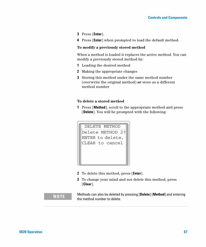
To delete a stored method
1 Press [Method], scroll to the appropriate method and press [Delete]. You will be prompted with the following:
2 To delete this method, press [Enter].
3 To change your mind and not delete this method, press [Clear].
DELETE METHODDelete METHOD 2?ENTER to delete, CLEAR to cancel
Methods can also be deleted by pressing [Delete] [Method] and entering
NOTEthe method number to delete.67
Controls and Components
How to Make a Setting
Entering setpoints
68
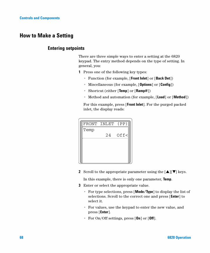
There are three simple ways to enter a setting at the 6820 keypad. The entry method depends on the type of setting. In general, you:
1 Press one of the following key types:
• Function (for example, [Front Inlet] or [Back Det])
• Miscellaneous (for example, [Options] or [Config])
• Shortcut (either [Temp] or [Ramp#])
• Method and automation (for example, [Load] or [Method])
For this example, press [Front Inlet]. For the purged packed inlet, the display reads:
2 Scroll to the appropriate parameter using the [▲][▼] keys.
In this example, there is only one parameter, Temp.
3 Enter or select the appropriate value.
• For type selections, press [Mode/Type] to display the list of selections. Scroll to the correct one and press [Enter] to select it.
• For values, use the keypad to enter the new value, and press [Enter].
• For On/Off settings, press [On] or [Off].
FRONT INLET (PP)Temp 24 Off<
6820 Operation
Controls and Components
6820 Operation
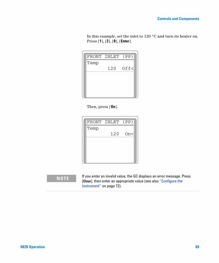
In this example, set the inlet to 120 °C and turn its heater on. Press [1], [2], [0], [Enter].
Then, press [On].
FRONT INLET (PP)Temp 120 Off<
FRONT INLET (PP)Temp 120 On<
If you enter an invalid value, the GC displays an error message. Press
NOTE[Clear], then enter an appropriate value (see also “Configure the Instrument” on page 72).69
Controls and Components
To turn a device On/Off
70
You can easily turn the heater on or off for inlets, detectors, the oven, and valves without changing its setpoint. Press the function key for the device, scroll to the temperature setting, and press [On] or [Off].
Some examples:
[Front Inlet], [Off] Turns the front inlet heater off[Aux#], [1], [Off] Turns auxiliary heated zone 1 off[Oven] [Off] Turns off the oven heater
6820 Operation
Agilent 6820 Gas ChromatographOperation
4Setting the Operating Parameters
Configure the Instrument 72
Configure the oven 72
Configure the inlets 73
Configure the valves 74
Configure your RS-232 communications settings 76
Setting the Column Oven Setpoints 79
Setting up an isothermal run 80
Setting up a single-ramp program 80
Setting up a multiple-ramp program 81
Setting the Inlet Parameters 82
Setting the Detector Parameters 84
Electron Capture Detector (ECD) 84
Flame Ionization Detector (FID) 85
Thermal Conductivity Detector (TCD) 86
Nitrogen Phosphorus Detector (NPD) 88
Controlling the Valves 90
Setting Auxiliary Heated Zones 94
Selecting Signal Output 95
This section completely describes how to use the 6820 keyboard to make settings for all of the hardware you have installed. It begins with the steps you need to take to set up (configure) your instrument for use, and then describes how to use the inlets, detectors, the column oven, and typical valves. It also provides the procedures needed to set signal outputs.
71Agilent Technologies
Setting the Operating Parameters
Configure the Instrument
72
The instrument will need to be configured before the first use and whenever changing or adding new hardware. Configuring the instrument sets global parameters, such as date and time, and also tells the instrument about the devices installed in it so that the GC can control them properly. Typically, configure the GC during installation and only modify the configuration as hardware changes.
Note that configuration settings directly affect your method. Unconfigured devices may be unavailable on the display, or may have no settable values. Also, these settings control the execution of certain tasks, for example, charging the sample loop of a gas sampling valve.
Set the time and date
The GC has an internal clock, and uses time and date for tasks such as logging methods and errors. To set the time and date:
1 Press [Config].
2 Scroll to the Time parameter, then press [Enter].
3 Scroll to the time and date lines, and use the keypad to enter the current values.
Configure the oven
Oven configuration sets the maximum temperature and equilibration time.
To configure the oven, press [Config], then select Oven and press [Enter]. Scroll to and enter:
• Maximum temp
• Equib time
Maximum temp Maximum allowable oven temperature setpoint. Columns and some accessories, such as the valves and the valve box have specific temperature limits. When configuring Maximum temp, consider these limits so that the
6820 Operation
Setting the Operating Parameters
6820 Operation
column and accessories are not damaged. Oven setpoints are verified as they are entered; a message is displayed when an entered setpoint is inconsistent with a previously defined maximum. The Maximum temp setpoint can be: 70 to 425 °C.
Equib time The time required for the oven temperature to equilibrate at a new temperature setting. Equilibration time begins when the actual oven temperature comes within 1 °C of the oven temperature setting. The Equib time setpoint can be 0 to 999.99 minutes. The default time is 3.00 minutes.
Configure the radix type
The 6820 GC is configurable for use with one of two radixes (decimal separators): the full stop (.) and the comma (,). Set the radix appropriate for your country.
1 Press [Options], scroll to Keybd & Display, and press [Enter]. The current radix setting is displayed.
2 To change the radix type, scroll to Radix Type, press [Mode/Type], scroll to the correct type, and press [Enter].
Configure the inlets
The GC knows whether or not an inlet is installed because it monitors the heater/sensor connections. However, it does not know what kind or type of inlet is present. Supply this information as follows:
1 Press the [Config] key.
2 Scroll to the Instrument parameter and press [Enter].
3 Scroll to the F inl type parameter.
4 If the inlet type listed is either Unknown or is incorrect for the front inlet, press [Mode/Type] to select the correct type.
5 Scroll to the correct inlet type, then press [Enter].
6 Press [Clear].
7 If a back inlet is installed, scroll to B inl type and repeat steps 4 through 6.
73
Setting the Operating Parameters
Configure the Aux thermal zones
74
The Aux (auxiliary) thermal zones control the heaters for devices such as a valve box or nickel catalyst. To configure a thermal Aux zone (1 or 2):
1 Press [Config], then [Aux #].
2 Press [Mode/Type], then select the type of device to be controlled by the zone and press [Enter].
If no Aux thermal zones are present, Not Installed appears in the display.
Configure the valves
If one or more valves are installed, configure them as follows:
1 Press [Config].
2 Scroll to Valve #, then press [Enter].
3 When prompted, input the number of the valve to configure. For example, to configure valve #1, press [1]. The GC displays valve #1’s type.
4 If the valve type is incorrect, press [Mode/Type], scroll to the correct valve type, and press [Enter].
Once the type is correct, the rest of the valve’s configuration parameters appear. Scroll to each parameter and input the correct information. Refer to Table 6 below.
Table 6 Valve configuration settings
Parameter Notes or value to enter
Valve types
Not installed No valve installed.
Gas sampling The valve is plumbed as a gas or liquid sampling valve.You may have two sampling valves installed.
6820 Operation
Setting the Operating Parameters
6820 Operation
Switching The valve is plumbed as a two-position a switching valve, for example, to redirect flow from one column to another.
Other Custom plumbing.
Additional gas sampling valve parameters
Loop volume Enter the sampling loop volume, in mL
Load time Enter the minimum time required to load the valve sample loop, in minutes.
Inject time Enter the time required to flush the sample onto the column.
Inlet Use the [Mode/Type] key to select the inlet (Front, Back, or None) that the valve injects into.
Table 6 Valve configuration settings (continued)
Parameter Notes or value to enter
Configure the setpoint status list
You can change the order of the setpoints shown in the setpoint status list. For example, you might want the three most important setpoints to appear first in the display when you press [Status].
1 Press [Config][Status] or press [Config], scroll down to Status then press [Enter].
2 Scroll to the setpoint that should appear first and press [Enter]. This setpoint will now appear at the top of the list.
3 Scroll to the setpoint that should appear second and press [Enter]. This setpoint will now be the second item on the list.
75
76
Setting the Operating Parameters
4 Continue editing until the list is in the order you wish.
Configure your RS-232 communications settings
Press [Config][Status]
a. Scroll to Signal 1 and press [Enter]. b. Signal 1 is now the first item on the list.
CONFIGURE STATUSOven tempTime leftFr inlet tempBk inlet tempSignal 1 <Signal 2
CONFIGURE STATUSSignal 1 <Oven tempTime leftFr inlet tempBk inlet tempSignal 2
Normally, the 6820 will be configured for proper RS-232 communications at the factory. However, if you need to check or alter the communications settings, do so as follows:
1 Press [Options], scroll to Communication, and press [Enter].
2 Scroll to each RS-232 setting, press [Mode/Type], and select the new value as needed. Table 7 lists the recommended settings.
Table 7 RS-232 communications parameters and default values
Parameter Default value for use with Cerity Chemical
Baud rate 19200
Handshake UART
Parity None
Data bits 8
Stop bits 1
End of command LF
6820 Operation
Setting the Operating Parameters
Configure your LAN communications
6820 Operation
The 6820 GC with LAN communications can set its IP address using the keyboard, or receive an IP address from a DHCP server.
To enter the IP address using the keyboard:
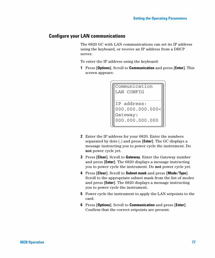
1 Press [Options]. Scroll to Communication and press [Enter]. This screen appears:
2 Enter the IP address for your 6820. Enter the numbers separated by dots (.) and press [Enter]. The GC displays a message instructing you to power cycle the instrument. Do not power cycle yet.
3 Press [Clear]. Scroll to Gateway. Enter the Gateway number and press [Enter]. The 6820 displays a message instructing you to power cycle the instrument. Do not power cycle yet.
4 Press [Clear]. Scroll to Subnet mask and press [Mode/Type]. Scroll to the appropriate subnet mask from the list of modes and press [Enter]. The 6820 displays a message instructing you to power cycle the instrument.
5 Power cycle the instrument to apply the LAN setpoints to the card.
6 Press [Options]. Scroll to Communication and press [Enter]. Confirm that the correct setpoints are present.
CommunicationLAN CONFIG
IP address:000.000.000.000<Gateway:000.000.000.000
77
78
Setting the Operating Parameters
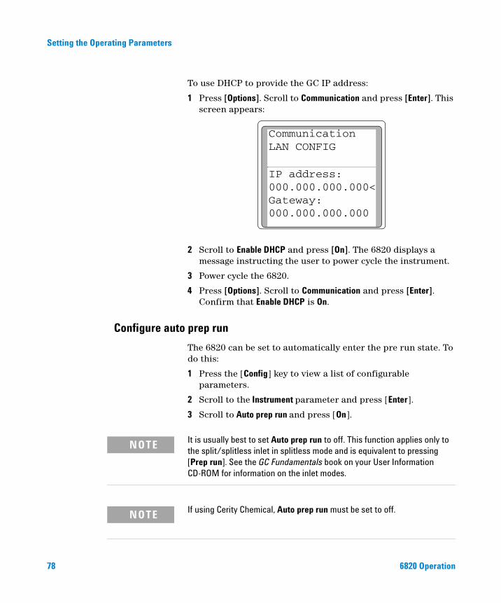
To use DHCP to provide the GC IP address:
1 Press [Options]. Scroll to Communication and press [Enter]. This screen appears:
2 Scroll to Enable DHCP and press [On]. The 6820 displays a message instructing the user to power cycle the instrument.
3 Power cycle the 6820.
4 Press [Options]. Scroll to Communication and press [Enter]. Confirm that Enable DHCP is On.
CommunicationLAN CONFIG
IP address:000.000.000.000<Gateway:000.000.000.000
Configure auto prep run
The 6820 can be set to automatically enter the pre run state. To do this:
1 Press the [Config] key to view a list of configurable parameters.
2 Scroll to the Instrument parameter and press [Enter].
3 Scroll to Auto prep run and press [On].
It is usually best to set Auto prep run to off. This function applies only to
NOTEthe split/splitless inlet in splitless mode and is equivalent to pressing [Prep run]. See the GC Fundamentals book on your User Information CD-ROM for information on the inlet modes.If using Cerity Chemical, Auto prep run must be set to off.
NOTE6820 Operation
Setting the Operating Parameters
Setting the Column Oven Setpoints
6820 Operation
Press [Oven] and press [On] or [Off] to turn the oven on or off, and to set the oven temperature profile. You can also press [Oven] to see the current oven temperature and the current setpoint value.
Oven setpoints
Table 8 describes the oven’s programmable setpoints.
Table 8 Oven programming setpoints
Setpoint During the run
Temp The current temperature setpoint for the oven.• While programming the oven temperature, Temp is the
starting temperature setpoint.• Once the run begins, the value of Temp changes with
the oven program. • Changing Temp during a run causes an immediate
change, but the value is not saved to the next run.
Init temp Displayed only during a run, Init Temp is set equal to Temp at the start of the run. When the run ends, the oven temperature is reset to the Init Temp value. Therefore, changing Init temp changes the starting temperature for the next run.
Init time Time in minutes that the oven will stay at the starting temperature after a programmed run has begun.
Rate The rate in °C/min at which the oven will be heated or cooled.
Final temp Temperature of the oven at the end of a heating or cooling rate.
Final time Time in minutes that the oven will be held at the final temperature of a temperature-programmed rate.
79
Setting the Operating Parameters
Setting up an isothermal run
80
An isothermal run is one in which the oven is maintained at a constant temperature. To create an isothermal run, set Rate 1 to zero.
1 Press [Oven] to access the oven parameter list.
2 Enter the oven temperature for the isothermal run.
3 Enter the number of minutes (Init time) that you want the oven to stay at this temperature. This time is the duration of the run.
4 If Rate 1 is not 0, enter zero for an isothermal run.
In addition to the isothermal run, you can also program up to five oven ramps. See “Setting up a single-ramp program” on page 80 and “Setting up a multiple-ramp program” on page 81.
OVEN Temp
30 30<Init time
0.00 Rate 1 (off)
0.00
Setting up a single-ramp program
To set up a single-ramp program:
1 Press [Oven] to access the oven parameter list.
2 Enter a starting temperature (Temp).
3 Enter the time (Init time) that you want the oven to stay at Temp.
4 Enter the rate (Rate 1) at which the oven temperature is to increase.
6820 Operation
Setting the Operating Parameters
6820 Operation
5 Enter the final temperature (Final temp 1).
6 Enter the time (Final time 1) the oven is to hold Final temp 1.
7 To end the oven ramp program after Ramp 1, set Rate 2 to zero.
Setting up a multiple-ramp program
Set up the first oven ramp as described on the preceding page.
In a multiple-ramp temperature program, the Final time for one ramp is also the Init time for the next ramp. Thus, there is only one Init time (before Ramp 1).
1 Enter the rate (Rate 2) at which you want the oven temperature to increase for the second oven ramp.
2 Enter the final temperature (Final temp 2).
3 Enter the number of minutes (Final time 2) that you want the oven to hold the final temperature.
4 To end the temperature program after Ramp 2, set Rate 3 to zero.
To add additional oven ramps, repeat the steps described above.
Total run time
Total length of a run is determined by the oven temperature program. If some other temperature program (for example, a nickel catalyst temperature program) is still running when the oven program ends, the run terminates anyway.
The maximum allowable time for a run is 999.99 minutes.
81
Setting the Operating Parameters
Setting the Inlet Parameters
82
The 6820 controls inlet temperature and mode (split/splitless inlet only) through the keypad. The inlet flow controls are located on the left side of the GC.
Before using your inlet for the first time, make sure it is properly configured. See “Configure the inlets” on page 73.
To use your inlets
Step Notes
1 Install the correct hardware, as needed:Split/Splitless inlet:• Liner• Column adapter• Septum• Gold seal (if needed)Purged packed inlet• Liner• Column adapter• Septum• Insert
See the Agilent 6820 GC Maintenance and Troubleshooting manual for the replacement or installation procedures.
2 Install the column and check for leaks. See the Agilent 6820 GC Maintenance and Troubleshooting manual.
3 Set the inlet operating temperature and turn it on.
a Press [Front Inlet] or [Back Inlet].
b Input the temperature setpoint and press [Enter].
6820 Operation
Setting the Operating Parameters
6820 Operation
4 After the inlet, oven, and detector reach temperature, set the inlet flow(s).
See “To Set the Split/Splitless Inlet Column and Split Vent Flows” on page 117 or “To Set the Purged Packed Inlet Column Flow” on page 121.
5 If using a split/splitless inlet, set the inlet mode.
See “Configure the inlets” on page 73See “Split/Splitless inlet” on page 167 for more information about the inlet mode.
To use your inlets (continued)
Step Notes
83
Setting the Operating Parameters
Setting the Detector Parameters
84
Press [Front Det] and [Back Det] to set run time parameters for the detectors or to view the detector’s raw output. The parameters for each detector type are described below.
Electron Capture Detector (ECD)
Electrometer
The Configure Detector parameter list contains an On/Off setting for the Electrometer. Normally, leave the electrometer on. You do not need to turn it on and off when operating your ECD. The only time you need to turn off the electrometer is when cleaning the detector.
Do not turn off the electrometer during a run. It will cancel detector
CAUTIONOutput.Using the ECD
Verify that your detector gases are connected, a column is properly installed, and the system is free of leaks. Set the oven temperature and the inlet temperature and flow.
To use the ECD
Step Notes
1 Install the correct column adapter. See the Agilent 6820 GC Maintenance and Troubleshooting manual.
2 Install the column and check for leaks. See the Agilent 6820 GC Maintenance and Troubleshooting manual.
3 Set the detector operating temperature and turn it on.
See “How to Make a Setting” on page 68.
6820 Operation
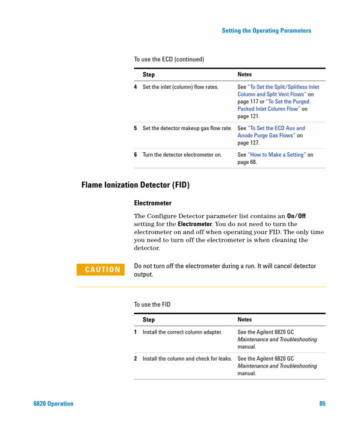
Setting the Operating Parameters
6820 Operation
4 Set the inlet (column) flow rates. See “To Set the Split/Splitless Inlet Column and Split Vent Flows” on page 117 or “To Set the Purged Packed Inlet Column Flow” on page 121.
5 Set the detector makeup gas flow rate. See “To Set the ECD Aux and Anode Purge Gas Flows” on page 127.
6 Turn the detector electrometer on. See “How to Make a Setting” on page 68.
To use the ECD (continued)
Step Notes
Flame Ionization Detector (FID)
Electrometer
The Configure Detector parameter list contains an On/Off setting for the Electrometer. You do not need to turn the electrometer on and off when operating your FID. The only time you need to turn off the electrometer is when cleaning the detector.
Do not turn off the electrometer during a run. It will cancel detector
CAUTIONoutput.To use the FID
Step Notes
1 Install the correct column adapter. See the Agilent 6820 GC Maintenance and Troubleshooting manual.
2 Install the column and check for leaks. See the Agilent 6820 GC Maintenance and Troubleshooting manual.
85
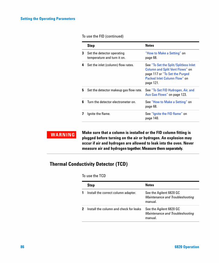
86
Setting the Operating Parameters
3 Set the detector operating temperature and turn it on.
“How to Make a Setting” on page 68.
4 Set the inlet (column) flow rates. See “To Set the Split/Splitless Inlet Column and Split Vent Flows” on page 117 or “To Set the Purged Packed Inlet Column Flow” on page 121.
5 Set the detector makeup gas flow rate. See “To Set FID Hydrogen, Air, and Aux Gas Flows” on page 123.
6 Turn the detector electrometer on. See “How to Make a Setting” on page 68.
7 Ignite the flame. See “Ignite the FID flame” on page 140.
To use the FID (continued)
Step Notes
Make sure that a column is installed or the FID column fitting is
Thermal Conductivity Detector (TCD)
WARNINGplugged before turning on the air or hydrogen. An explosion may occur if air and hydrogen are allowed to leak into the oven. Never measure air and hydrogen together. Measure them separately.
To use the TCD
Step Notes
1 Install the correct column adapter. See the Agilent 6820 GC Maintenance and Troubleshooting manual.
2 Install the column and check for leaks See the Agilent 6820 GC Maintenance and Troubleshooting manual.
6820 Operation
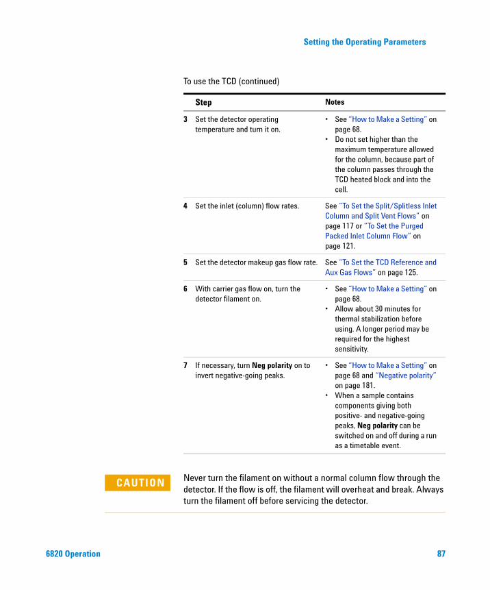
Setting the Operating Parameters
6820 Operation
3 Set the detector operating temperature and turn it on.
• See “How to Make a Setting” on page 68.
• Do not set higher than the maximum temperature allowed for the column, because part of the column passes through the TCD heated block and into the cell.
4 Set the inlet (column) flow rates. See “To Set the Split/Splitless Inlet Column and Split Vent Flows” on page 117 or “To Set the Purged Packed Inlet Column Flow” on page 121.
5 Set the detector makeup gas flow rate. See “To Set the TCD Reference and Aux Gas Flows” on page 125.
6 With carrier gas flow on, turn the detector filament on.
• See “How to Make a Setting” on page 68.
• Allow about 30 minutes for thermal stabilization before using. A longer period may be required for the highest sensitivity.
7 If necessary, turn Neg polarity on to invert negative-going peaks.
• See “How to Make a Setting” on page 68 and “Negative polarity” on page 181.
• When a sample contains components giving both positive- and negative-going peaks, Neg polarity can be switched on and off during a run as a timetable event.
To use the TCD (continued)
Step Notes
Never turn the filament on without a normal column flow through the
CAUTIONdetector. If the flow is off, the filament will overheat and break. Always turn the filament off before servicing the detector.87
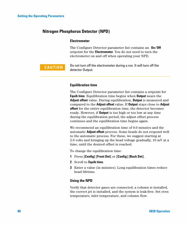
Setting the Operating Parameters
Nitrogen Phosphorus Detector (NPD)
88
Electrometer
The Configure Detector parameter list contains an On/Off setpoint for the Electrometer. You do not need to turn the electrometer on and off when operating your NPD.
Do not turn off the electrometer during a run. It will turn off the
CAUTIONdetector Output.Equilibration time
The Configure Detector parameter list contains a setpoint for Equib time. Equilibration time begins when Output nears the Adjust offset value. During equilibration, Output is measured and compared to the Adjust offset value. If Output stays close to Adjust offset for the entire equilibration time, the detector becomes ready. However, if Output is too high or too low at any time during the equilibration period, the adjust offset process continues and the equilibration time begins again.
We recommend an equilibration time of 0.0 minutes and the automatic Adjust offset process. Some beads do not respond well to the automatic process. For these, we suggest starting at 2.0 volts and bringing up the bead voltage gradually, 10 mV at a time, until the desired offset is reached.
To change the equilibration time:
1 Press [Config] [Front Det] or [Config] [Back Det].
2 Scroll to Equib time.
3 Enter a value (in minutes). Long equilibration times reduce bead lifetime.
Using the NPD
Verify that detector gases are connected, a column is installed, the correct jet is installed, and the system is leak-free. Set oven temperature, inlet temperature, and column flow.
6820 Operation
Setting the Operating Parameters
6820 Operation
To use the NPD
Step Notes
1 Install the correct column adapter. See the Agilent 6820 GC Maintenance and Troubleshooting manual.
2 Install the column and check for leaks. See the Agilent 6820 GC Maintenance and Troubleshooting manual.
3 Set the detector operating temperature and turn it on.
“How to Make a Setting” on page 68.
4 Set the inlet (column) flow rates. See “To Set the Split/Splitless Inlet Column and Split Vent Flows” on page 117 or “To Set the Purged Packed Inlet Column Flow” on page 121.
5 Set the detector makeup gas flow rate. See “To Set NPD Hydrogen, Air, and Aux Gas Flows” on page 128.
6 Enter Adjust offset number, or press [On] to begin the adjustment process.
You may manually adjust bead voltage to let the output reach the expected value.
See “How to Make a Setting” on page 68 and “Equilibration time” on page 88.
89
Setting the Operating Parameters
Controlling the Valves
90
Make valve temperature settings using the appropriate [Aux#] heated zone. Control its use during the run as described below.
To use a valve
Step Notes
1 Configure the valve. See “Configure the valves” on page 74.
2 If desired, set up a Run Table to control the valve.
See “Run Time Programming: Using Run Time Events” on page 153.
3 Set the valve box temperature, if needed.
See “Setting Auxiliary Heated Zones” on page 94.
4 If not using Run Table control, press [Valve#] when ready to start the run.
Controlling valves from the keyboard
The 6820 valves have two positions controlled by the [On] and [Off] keys. The keyboard commands for two-position valves are:
[Valve#] <valve number> [On] (rotates valve to one stop)
and
[Valve#] <valve number> [Off] (rotates valve to the other stop)
Controlling valves from the run time tables
The Valve On and Valve Off commands can be run time programmed. See “Run Time Programming: Using Run Time Events” on page 153 and “Programming the Clock Table” on page 144.
If a valve is rotated by a run time program, it is not automatically returned to its initial position at the end of the run. You must program this reset operation yourself.
6820 Operation
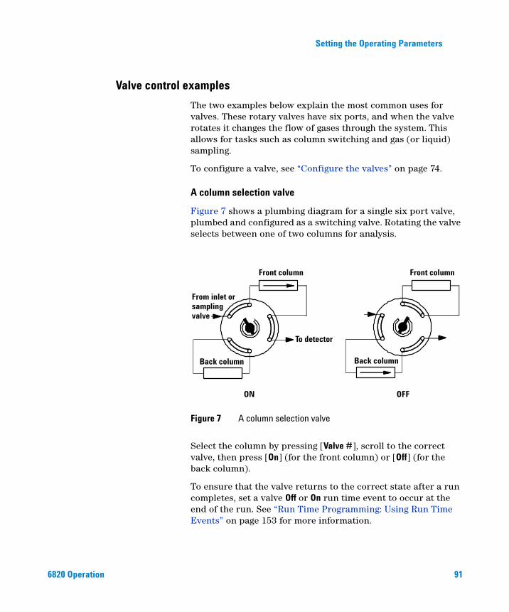
Setting the Operating Parameters
Valve control examples
6820 Operation
The two examples below explain the most common uses for valves. These rotary valves have six ports, and when the valve rotates it changes the flow of gases through the system. This allows for tasks such as column switching and gas (or liquid) sampling.
To configure a valve, see “Configure the valves” on page 74.
A column selection valve
Figure 7 shows a plumbing diagram for a single six port valve, plumbed and configured as a switching valve. Rotating the valve selects between one of two columns for analysis.
Select the column by pressing [Valve #], scroll to the correct valve, then press [On] (for the front column) or [Off] (for the back column).
To ensure that the valve returns to the correct state after a run completes, set a valve Off or On run time event to occur at the end of the run. See “Run Time Programming: Using Run Time Events” on page 153 for more information.
Figure 7 A column selection valve
Front column Front column
To detector
Back column Back column
ON OFF
From inlet orsamplingvalve
91
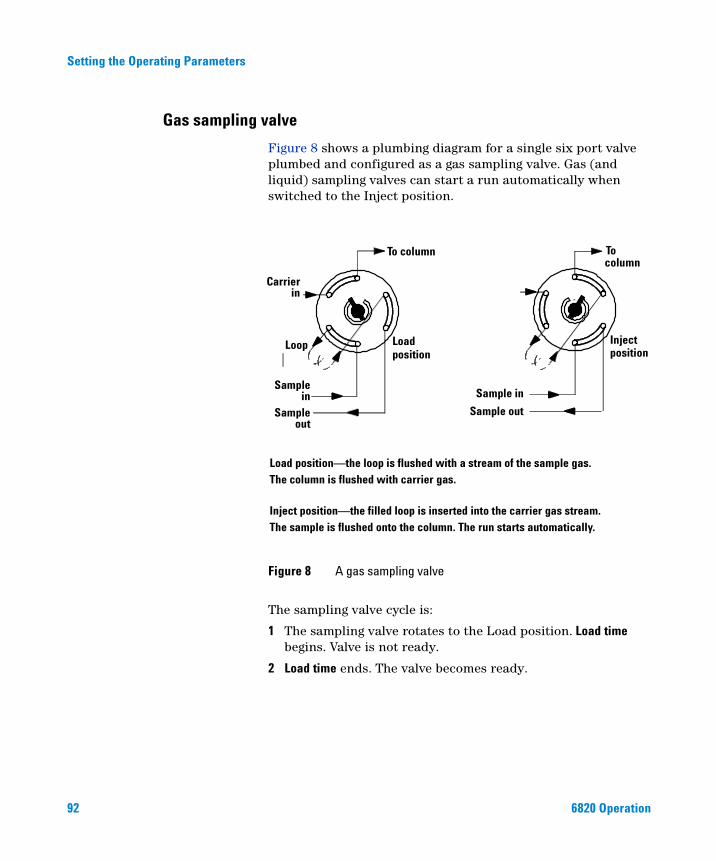
Setting the Operating Parameters
Gas sampling valve
92
Figure 8 shows a plumbing diagram for a single six port valve plumbed and configured as a gas sampling valve. Gas (and liquid) sampling valves can start a run automatically when switched to the Inject position.
The sampling valve cycle is:
1 The sampling valve rotates to the Load position. Load time begins. Valve is not ready.
2 Load time ends. The valve becomes ready.
Figure 8 A gas sampling valve
To column To
Injectposition
Sample in
Sample out
Sample
Sample
Carrier
Load position
Loop
Load position—the loop is flushed with a stream of the sample gas.The column is flushed with carrier gas.
Inject position—the filled loop is inserted into the carrier gas stream.The sample is flushed onto the column. The run starts automatically.
out
in
in
column
6820 Operation
Setting the Operating Parameters
6820 Operation
3 If everything else is ready, the GC becomes ready.If everything else is not ready:
• If you are using Clock Table, the GC waits until everything is ready, then executes the valve inject command.
• If you are not using Clock Table, the valve injection can be made at any time from the keyboard.
4 The sampling valve rotates (keyboard command) to the Inject position. Inject time begins. The run begins.
5 Inject time ends. Return to step 1.
See also “Run a Sample Using a Sampling Valve” on page 138.
93
Setting the Operating Parameters
Setting Auxiliary Heated Zones
General comments
94
If available, use the auxiliary heated zone to control the temperature of an installed accessory. The most common device is a valve box.
To set the temperature of the heated zone:
1 Press [Aux#], and input the number of the zone (1 or 2).
2 Input the temperature and press [Enter].
6820 Operation
Setting the Operating Parameters
Selecting Signal Output
6820 Operation
Use the [Signal 1] and [Signal 2] keys to set up and assign the output from the GC. The setup can include the signal type, analog data rate (if using an analog device), and column compensation profile(s). Note that if you are using only a digital data system such as Cerity Chemical, you do not need to set the analog data rate.
Setting signals
Type
To set up a signal, first select the type of data to be sent to the data collection device:
1 Press [Signal 1] or [Signal 2].
2 Scroll to Type and press [Mode/Type]. In the list presented, scroll to the appropriate signal output and press [Enter] to select it.
NOTE In general, set Signal 1 to use the output from the front detector (and front inlet and column1). Set Signal 2 to use the output from the back detector.
3 If using analog output, scroll to Zero and either enter the offset value (from –500000 to +500000), or press [On] to set Zero at the current signal value (displayed).
4 If using analog output, scroll to Range and enter a value from 0 to 13.
For more information about signal types and settings, see “Signal Handling” on page 198.
Analog data rate
If using analog output to an integrator, you may also need to configure the signal output data rate. Analog output for the detectors can be presented at either of two speeds. The faster speed allows minimum peak widths of 0.004 minutes (8 Hz
95
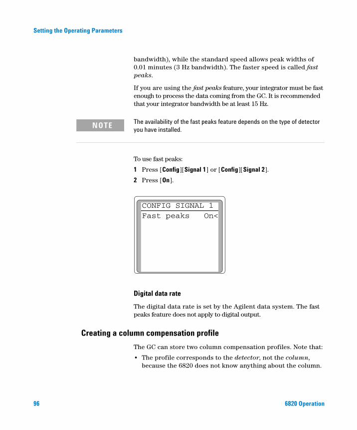
96
Setting the Operating Parameters
bandwidth), while the standard speed allows peak widths of 0.01 minutes (3 Hz bandwidth). The faster speed is called fast peaks.
If you are using the fast peaks feature, your integrator must be fast enough to process the data coming from the GC. It is recommended that your integrator bandwidth be at least 15 Hz.
The availability of the fast peaks feature depends on the type of detector
NOTEyou have installed.To use fast peaks:
1 Press [Config][Signal 1] or [Config][Signal 2].
2 Press [On].
Digital data rate
The digital data rate is set by the Agilent data system. The fast peaks feature does not apply to digital output.
CONFIG SIGNAL 1Fast peaks On<
Creating a column compensation profile
The GC can store two column compensation profiles. Note that:
• The profile corresponds to the detector, not the column, because the 6820 does not know anything about the column.
6820 Operation
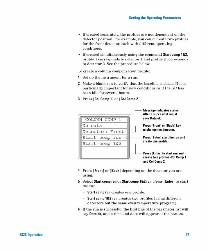
Setting the Operating Parameters
6820 Operation
• If created separately, the profiles are not dependent on the detector position. For example, you could create two profiles for the front detector, each with different operating conditions.
• If created simultaneously using the command Start comp 1&2, profile 1 corresponds to detector 1 and profile 2 corresponds to detector 2. See the procedure below.
To create a column compensation profile:
1 Set up the instrument for a run.
2 Make a blank run to verify that the baseline is clean. This is particularly important for new conditions or if the GC has been idle for several hours.
3 Press [Col Comp 1] or [Col Comp 2].
4 Press [Front] or [Back] depending on the detector you are using.
5 Select Start comp run or Start comp 1&2 run. Press [Enter] to start the run.
• Start comp run creates one profile.
• Start comp 1&2 run creates two profiles (using different detectors but the same oven temperature program).
6 If the run is successful, the first line of the parameter list will say Data ok, and a time and date will appear at the bottom.
Message indicates status.After a successful run, itsays Data ok.
Press [Front] or [Back] keyto change the detector.
Press [Enter] start the run and
Press [Enter] to start run andcreate two profiles-Col Comp 1and Col Comp 2.
COLUMN COMP 1No dataDetector: FrontStart comp run <Start comp 1&2 create one profile.
97
Setting the Operating Parameters
Making a run using column compensation
98
After creating a column compensation profile, use it as follows:
1 Set the up chromatographic conditions. They must be identical to those in the stored column compensation run except that Final time in the last ramp of the oven program can be longer or shorter.
2 Press [Signal 1] or [Signal 2] as applicable.
3 Scroll to Type: and press [Mode/Type].
4 Choose Front - col comp 1 or one of the other three column compensation options on the list. For a description of the choices, see Table 35 on page 198.
5 Enter setpoints for Zero and Range if applicable. See “Analog data rate” on page 95 for more information.
6 Start your run.
Plotting a stored column compensation profile
To look at a stored column compensation profile, output it to your data system as follows:
1 Press [Signal 1] or [Signal 2] as applicable.
2 Scroll to Type: and press [Mode/Type].
3 Choose Col comp 1 or Col comp 2.
4 Press [Start].
Once the profile is output, print it using your integrator or data system.
6820 Operation
Agilent 6820 Gas ChromatographOperation
5Setting Flows
About 6820 Flow Control 100
Tips 100
Maximum operating pressure 100
Where to Measure Flows 101
Detector and column flows 101
Inlet vent and septum purge flows 103
6820 Flow Controls 104
Single detector configurations 107
Two-detector configurations 110
To Set the GC Flows 116
To Set the Split/Splitless Inlet Column and Split Vent Flows 117
To Set the Purged Packed Inlet Column Flow 121
To Set FID Hydrogen, Air, and Aux Gas Flows 123
To Set the TCD Reference and Aux Gas Flows 125
To Set the ECD Aux and Anode Purge Gas Flows 127
To Set NPD Hydrogen, Air, and Aux Gas Flows 128
Adapters for Measuring Flow Rates 130
How to Measure Flow Rates Using a Bubble Meter 131
Measuring gas flows with a bubble meter 131
This section describes how to set the gas flows used in the 6820. It also describes how to measure flows using a typical bubble flow meter and the instrument’s internal stopwatch.
99Agilent Technologies
Setting Flows
About 6820 Flow Control
100
This section describes how to set the various flow rates in your instrument.
Tips
When setting flow rates, please keep the following tips in mind:
• The instructions recommend starting pressures and flows. Adjust the source pressures, as needed, for your analysis.
• You can set the flow rates with all GC components (inlet, column oven, detector) at either ambient temperature or at an appropriate operating temperature. To achieve the most repeatable results, always use the same technique.
• If setting flows at an elevated temperature, be sure to keep carrier gas flowing through the column at all times.
• To set flows at an elevated temperature, first download the appropriate Cerity Chemical method to the GC.
• Set the inlet carrier gas flow before setting detector flows.
• If you cannot obtain the inlet flow you need, you may need to change the flow restrictor(s) in the flow module.
WARNING If setting flows at operating temperature, the detector and exhaust gases may be hot enough to cause burns. Wear heat-resistant gloves when attaching and using the flow meter and adapters.
If the carrier gas source runs out of gas or is turned off, the column
Maximum operating pressure
CAUTIONmay be damaged if heated without carrier gas flow.
The 6820 inlets and detectors are rated for carrier gas supply pressures up to 0.7 MPa (100 psi). Operating the GC with higher pressures can cause leaks.
6820 Operation
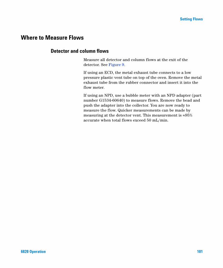
Setting Flows
Where to Measure Flows
Detector and column flows
6820 Operation
Measure all detector and column flows at the exit of the detector. See Figure 9.
If using an ECD, the metal exhaust tube connects to a low pressure plastic vent tube on top of the oven. Remove the metal exhaust tube from the rubber connector and insert it into the flow meter.
If using an NPD, use a bubble meter with an NPD adapter (part number G1534-60640) to measure flows. Remove the bead and push the adapter into the collector. You are now ready to measure the flow. Quicker measurements can be made by measuring at the detector vent. This measurement is ≈95% accurate when total flows exceed 50 mL/min.
101
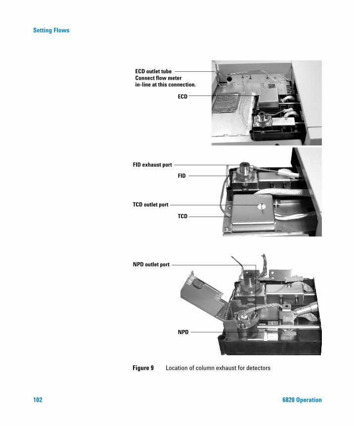
102
Setting Flows
Figure 9 Location of column exhaust for detectors
ECD outlet tube
FID exhaust port
TCD outlet port
ECD
FID
TCD
Connect flow meterin-line at this connection.
NPD
NPD outlet port
6820 Operation
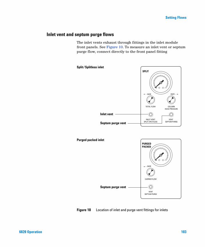
Setting Flows
Inlet vent and septum purge flows
6820 Operation
The inlet vents exhaust through fittings in the inlet module front panels. See Figure 10. To measure an inlet vent or septum purge flow, connect directly to the front panel fitting
Figure 10 Location of inlet and purge vent fittings for inlets
Septum purge vent
Inlet vent
Septum purge vent
Split/Splitless inlet
Purged packed inletPURGED
CARRIER FLOW
SEPTUM PURGEVENT
PACKED
SPLIT
TOTAL FLOW COLUMNHEAD PRESSURE
INLET VENTSPLIT/SPLITLESS
VENTSEPTUM PURGE
INCR INCR
INCR
103
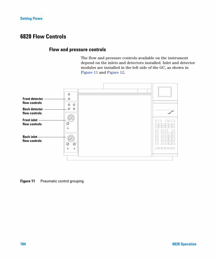
Setting Flows
6820 Flow Controls
Flow and pressure controls
104
The flow and pressure controls available on the instrument depend on the inlets and detectors installed. Inlet and detector modules are installed in the left side of the GC, as shown in Figure 11 and Figure 12.
Figure 11 Pneumatic control grouping
Front detector
Back detector
Front inlet
Back inlet
flow controls
flow controls
flow controls
flow controls
6820 Operation
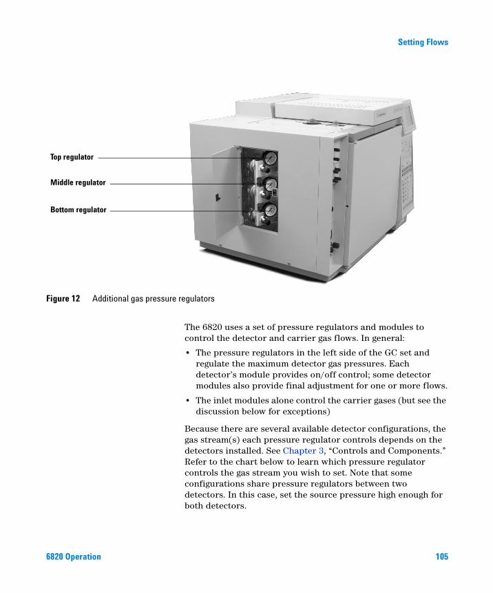
Setting Flows
Figure 12 Additional gas pressure regulators
Top regulator
Middle regulator
Bottom regulator
6820 Operation
The 6820 uses a set of pressure regulators and modules to control the detector and carrier gas flows. In general:
• The pressure regulators in the left side of the GC set and regulate the maximum detector gas pressures. Each detector’s module provides on/off control; some detector modules also provide final adjustment for one or more flows.
• The inlet modules alone control the carrier gases (but see the discussion below for exceptions)
Because there are several available detector configurations, the gas stream(s) each pressure regulator controls depends on the detectors installed. See Chapter 3, “Controls and Components.” Refer to the chart below to learn which pressure regulator controls the gas stream you wish to set. Note that some configurations share pressure regulators between two detectors. In this case, set the source pressure high enough for both detectors.
105
106
Setting Flows
The regulator configurations provide sufficient range of control for most operating conditions.
Detector(s) installed Refer to this table
FID Table 9 on page 107
TCD Table 9 on page 107
ECD Table 9 on page 107
NPD Table 9 on page 107
FID + FID Table 10 on page 110
ECD + FID Table 11 on page 110
NPD + FID Table 12 on page 111
TCD + TCD Table 13 on page 111
NPD + NPD Table 14 on page 112
TCD + FID Table 15 on page 112
TCD + ECD Table 16 on page 113
TCD + NPD Table 17 on page 113
ECD + ECD Table 18 on page 114
ECD + NPD Table 19 on page 114
6820 Operation
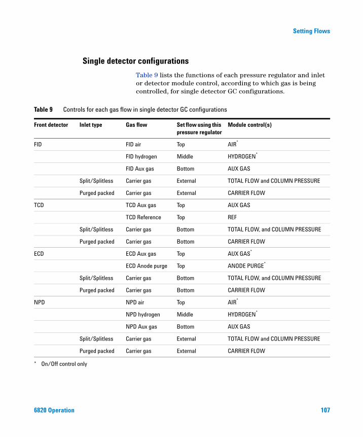
Setting Flows
Single detector configurations
6820 Operation
Table 9 lists the functions of each pressure regulator and inlet or detector module control, according to which gas is being controlled, for single detector GC configurations.
in single detector GC configurations
Table 9 Controls for each gas flowFront detector Inlet type Gas flow Set flow using this pressure regulator
Module control(s)
FID FID air Top AIR*
FID hydrogen Middle HYDROGEN*
FID Aux gas Bottom AUX GAS
Split/Splitless Carrier gas External TOTAL FLOW and COLUMN PRESSURE
Purged packed Carrier gas External CARRIER FLOW
TCD TCD Aux gas Top AUX GAS
TCD Reference Top REF
Split/Splitless Carrier gas Bottom TOTAL FLOW, and COLUMN PRESSURE
Purged packed Carrier gas Bottom CARRIER FLOW
ECD ECD Aux gas Top AUX GAS*
ECD Anode purge Top ANODE PURGE*
Split/Splitless Carrier gas Bottom TOTAL FLOW, and COLUMN PRESSURE
Purged packed Carrier gas Bottom CARRIER FLOW
NPD NPD air Top AIR*
NPD hydrogen Middle HYDROGEN*
NPD Aux gas Bottom AUX GAS
Split/Splitless Carrier gas External TOTAL FLOW and COLUMN PRESSURE
Purged packed Carrier gas External CARRIER FLOW
* On/Off control only
107
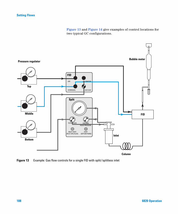
108
Setting Flows
Figure 13 and Figure 14 give examples of control locations for two typical GC configurations.
Figure 13 Example: Gas flow controls for a single FID with split/splitless inlet
Pressure regulator
Top
Middle
Bottom
Split
FID
AUX GAS
FID IGNITORAIR
HYDROGEN
Column
Inlet
FID
Bubble meter
TOTAL FLOW COLUMNHEAD PRESSURE
INLET VENTSPLIT/SPLITLESS
VENTSEPTUM PURGE
6820 Operation
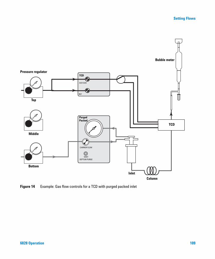
Setting Flows
Figure 14 Example: Gas flow controls for a TCD with purged packed inlet
Pressure regulator
Top
Middle
Bottom
Purged
TCD
AUX GAS
REF
CARRIER FLOW
SEPTUM PURGE
Column
Inlet
TCD
Bubble meter
VENT
Packed
6820 Operation 109
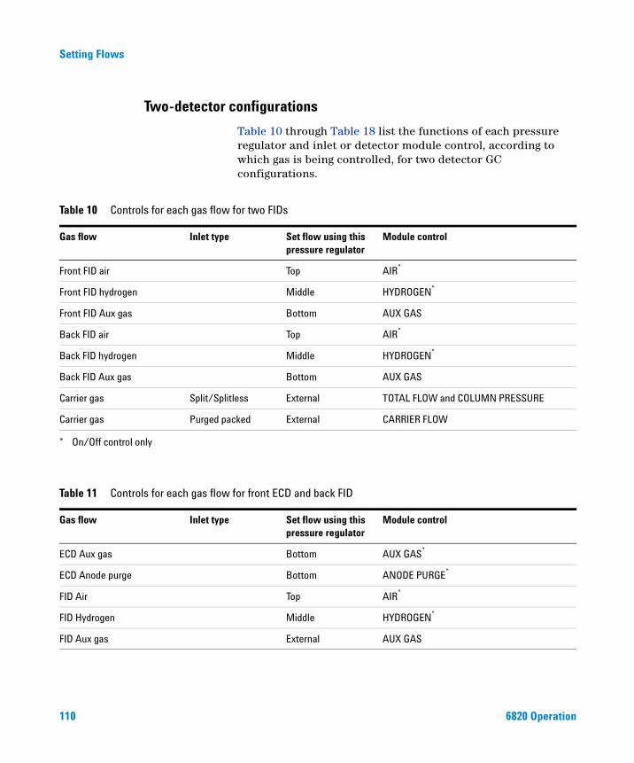
Setting Flows
Two-detector configurations
110
Table 10 through Table 18 list the functions of each pressure regulator and inlet or detector module control, according to which gas is being controlled, for two detector GC configurations.
Table 10 Controls for each gas flow for two FIDs
Gas flow Inlet type Set flow using this pressure regulator
Module control
Front FID air Top AIR*
Front FID hydrogen Middle HYDROGEN*
Front FID Aux gas Bottom AUX GAS
Back FID air Top AIR*
Back FID hydrogen Middle HYDROGEN*
Back FID Aux gas Bottom AUX GAS
Carrier gas Split/Splitless External TOTAL FLOW and COLUMN PRESSURE
Carrier gas Purged packed External CARRIER FLOW
* On/Off control only
for front ECD and back FID
Table 11 Controls for each gas flowGas flow Inlet type Set flow using this pressure regulator
Module control
ECD Aux gas Bottom AUX GAS*
ECD Anode purge Bottom ANODE PURGE*
FID Air Top AIR*
FID Hydrogen Middle HYDROGEN*
FID Aux gas External AUX GAS
6820 Operation
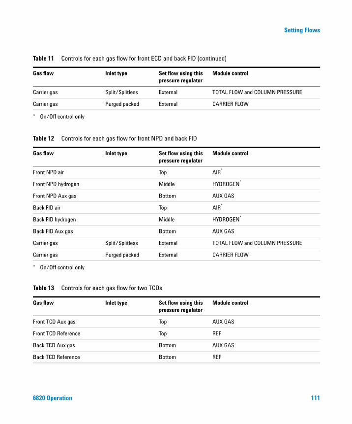
Setting Flows
Carrier gas Split/Splitless External TOTAL FLOW and COLUMN PRESSURE
Carrier gas Purged packed External CARRIER FLOW
* On/Off control only
Table 12 Controls for each gas flow for front NPD and back FID
Gas flow Inlet type Set flow using this pressure regulator
Module control
Front NPD air Top AIR*
* On/Off control only
Front NPD hydrogen Middle HYDROGEN*
Front NPD Aux gas Bottom AUX GAS
Back FID air Top AIR*
Back FID hydrogen Middle HYDROGEN*
Back FID Aux gas Bottom AUX GAS
Carrier gas Split/Splitless External TOTAL FLOW and COLUMN PRESSURE
Carrier gas Purged packed External CARRIER FLOW
Table 13 Controls for each gas flow for two TCDs
Gas flow Inlet type Set flow using this pressure regulator
Module control
Front TCD Aux gas Top AUX GAS
Front TCD Reference Top REF
Back TCD Aux gas Bottom AUX GAS
Back TCD Reference Bottom REF
Table 11 Controls for each gas flow for front ECD and back FID (continued)
Gas flow Inlet type Set flow using this pressure regulator
Module control
6820 Operation 111
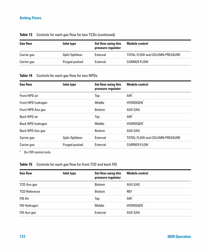
Setting Flows
Carrier gas Split/Splitless External TOTAL FLOW and COLUMN PRESSURE
Carrier gas Purged packed External CARRIER FLOW
Table 14 Controls for each gas flow for two NPDs
Gas flow Inlet type Set flow using this pressure regulator
Module control
Front NPD air Top AIR*
* On/Off control only
Front NPD hydrogen Middle HYDROGEN*
Front NPD Aux gas Bottom AUX GAS
Back NPD air Top AIR*
Back NPD hydrogen Middle HYDROGEN*
Back NPD Aux gas Bottom AUX GAS
Carrier gas Split/Splitless External TOTAL FLOW and COLUMN PRESSURE
Carrier gas Purged packed External CARRIER FLOW
Table 15 Controls for each gas flow for front TCD and back FID
Gas flow Inlet type Set flow using this pressure regulator
Module control
TCD Aux gas Bottom AUX GAS
TCD Reference Bottom REF
FID Air Top AIR*
FID Hydrogen Middle HYDROGEN*
FID Aux gas External AUX GAS
Table 13 Controls for each gas flow for two TCDs (continued)
Gas flow Inlet type Set flow using this pressure regulator
Module control
112 6820 Operation
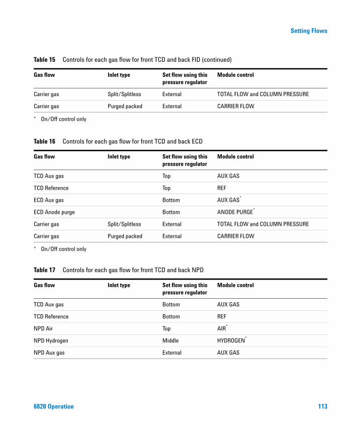
Setting Flows
Carrier gas Split/Splitless External TOTAL FLOW and COLUMN PRESSURE
Carrier gas Purged packed External CARRIER FLOW
* On/Off control only
Table 16 Controls for each gas flow for front TCD and back ECD
Gas flow Inlet type Set flow using this pressure regulator
Module control
TCD Aux gas Top AUX GAS
TCD Reference Top REF
ECD Aux gas Bottom AUX GAS*
* On/Off control only
ECD Anode purge Bottom ANODE PURGE*
Carrier gas Split/Splitless External TOTAL FLOW and COLUMN PRESSURE
Carrier gas Purged packed External CARRIER FLOW
Table 17 Controls for each gas flow for front TCD and back NPD
Gas flow Inlet type Set flow using this pressure regulator
Module control
TCD Aux gas Bottom AUX GAS
TCD Reference Bottom REF
NPD Air Top AIR*
NPD Hydrogen Middle HYDROGEN*
NPD Aux gas External AUX GAS
Table 15 Controls for each gas flow for front TCD and back FID (continued)
Gas flow Inlet type Set flow using this pressure regulator
Module control
6820 Operation 113
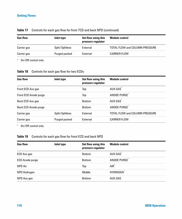
Setting Flows
Carrier gas Split/Splitless External TOTAL FLOW and COLUMN PRESSURE
Carrier gas Purged packed External CARRIER FLOW
* On/Off control only
Table 18 Controls for each gas flow for two ECDs
Gas flow Inlet type Set flow using this pressure regulator
Module control
Front ECD Aux gas Top AUX GAS*
* On/Off control only
Front ECD Anode purge Top ANODE PURGE*
Back ECD Aux gas Bottom AUX GAS*
Back ECD Anode purge Bottom ANODE PURGE*
Carrier gas Split/Splitless External TOTAL FLOW and COLUMN PRESSURE
Carrier gas Purged packed External CARRIER FLOW
Table 19 Controls for each gas flow for front ECD and back NPD
Gas flow Inlet type Set flow using this pressure regulator
Module control
ECD Aux gas Bottom AUX GAS*
ECD Anode purge Bottom ANODE PURGE*
NPD Air Top AIR*
NPD Hydrogen Middle HYDROGEN*
NPD Aux gas Bottom AUX GAS
Table 17 Controls for each gas flow for front TCD and back NPD (continued)
Gas flow Inlet type Set flow using this pressure regulator
Module control
114 6820 Operation
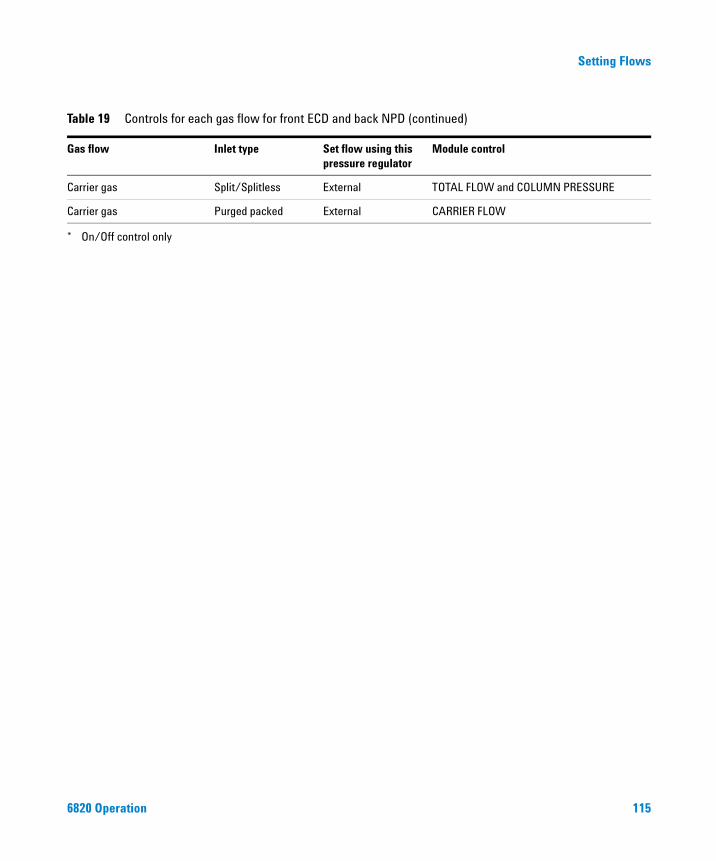
Setting Flows
Carrier gas Split/Splitless External TOTAL FLOW and COLUMN PRESSURE
Carrier gas Purged packed External CARRIER FLOW
* On/Off control only
Table 19 Controls for each gas flow for front ECD and back NPD (continued)
Gas flow Inlet type Set flow using this pressure regulator
Module control
6820 Operation 115
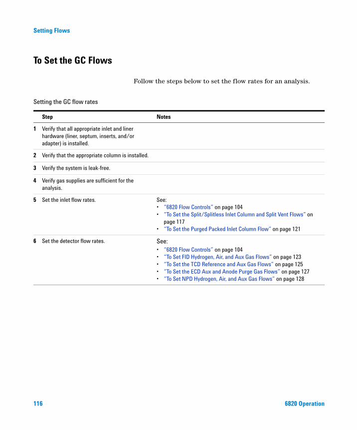
Setting Flows
To Set the GC Flows
116
Follow the steps below to set the flow rates for an analysis.
Setting the GC flow rates
Step Notes
1 Verify that all appropriate inlet and liner hardware (liner, septum, inserts, and/or adapter) is installed.
2 Verify that the appropriate column is installed.
3 Verify the system is leak-free.
4 Verify gas supplies are sufficient for the analysis.
5 Set the inlet flow rates. See: • “6820 Flow Controls” on page 104• “To Set the Split/Splitless Inlet Column and Split Vent Flows” on
page 117• “To Set the Purged Packed Inlet Column Flow” on page 121
6 Set the detector flow rates. See:• “6820 Flow Controls” on page 104• “To Set FID Hydrogen, Air, and Aux Gas Flows” on page 123• “To Set the TCD Reference and Aux Gas Flows” on page 125• “To Set the ECD Aux and Anode Purge Gas Flows” on page 127• “To Set NPD Hydrogen, Air, and Aux Gas Flows” on page 128
6820 Operation
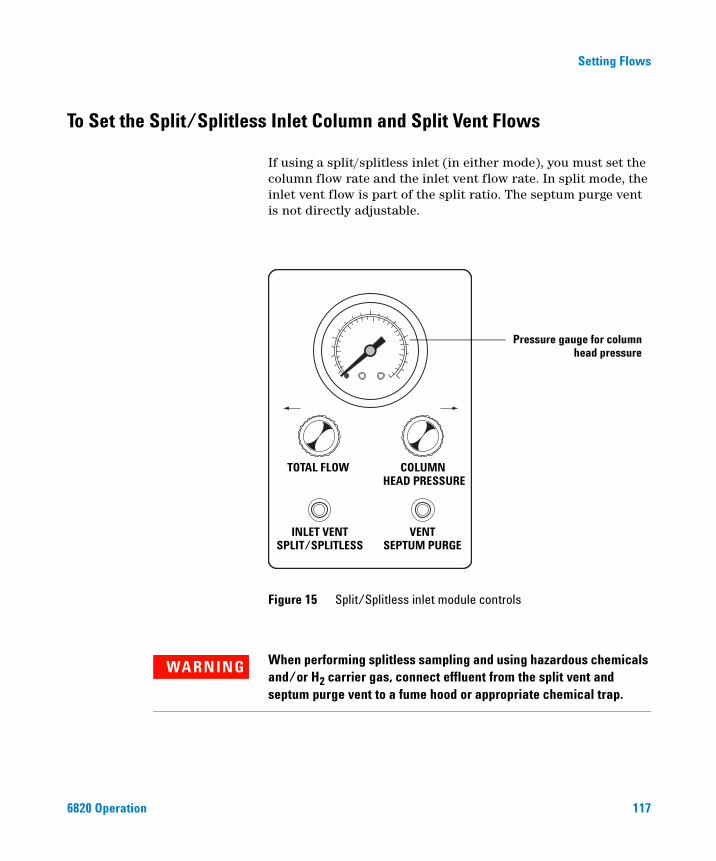
Setting Flows
To Set the Split/Splitless Inlet Column and Split Vent Flows
6820 Operation
If using a split/splitless inlet (in either mode), you must set the column flow rate and the inlet vent flow rate. In split mode, the inlet vent flow is part of the split ratio. The septum purge vent is not directly adjustable.
Figure 15 Split/Splitless inlet module controls
TOTAL FLOW COLUMN HEAD PRESSURE
INLET VENTSPLIT/SPLITLESS
VENTSEPTUM PURGE
Pressure gauge for columnhead pressure
WARNING When performing splitless sampling and using hazardous chemicals and/or H2 carrier gas, connect effluent from the split vent and septum purge vent to a fume hood or appropriate chemical trap.
117
118
Setting Flows
To ensure proper operation, make sure the carrier source pressure is at least 0.1 MPa (15 psi) greater than the selected column head pressure.
CAUTION If your instrument contains a TCD, turn off the TCD filament before setting the flow rates. Operating the TCD filament without carrier gas flow can damage the filament.
1 If using a TCD, turn off the detector filament. Press [Front Det] or [Back Det], scroll to Filament, then press [Off].
2 Locate the knob labeled TOTAL FLOW. Turn it clockwise as far as it will go. Do not force the knob; when it closes, it comes to a slightly “soft” stop.
3 Set the external source pressure regulator 0.07 to 0.14 MPa (10 to 20 psi) higher than the pressure required on the GC internal regulator. For example:
See “6820 Flow Controls” on page 104 for details on regulator usage.
4 If used, set the internal 6820 carrier gas regulator pressure. A typical starting value is 0.41 MPa (60 psi).
Carrier source pressure must be at least 0.1 MPa (15 psi) greater than the maximum column head pressure.
5 Set the oven temperature to the specified initial value. Wait for the temperature to stabilize.
Does inlet use an internal regulator?
Pressure Yes No
External regulator pressure
0.55 MPa (80 psi) 0.41 MPa (60 psi)
Internal regulator pressure
0.41 MPa (60 psi) —
Maximum desired column pressure
0.28 MPa (40 psi) 0.28 MPa (40 psi)
6820 Operation
Setting Flows
6820 Operation
6 Attach a flow meter to the detector outlet. See “Where to Measure Flows” on page 101. There should be no flow at this time. If there is, turn the detector gas flows off.
7 Turn the TOTAL FLOW knob in the ← INCR direction to turn the carrier gas flow on.
8 Turn the COLUMN HEAD PRESSURE knob in the INCR→ direction. The pressure will slowly rise. Adjust and measure to achieve the desired column flow. If you cannot, increase TOTAL FLOW until you can. Use TOTAL FLOW for coarse and COLUMN HEAD PRESSURE for fine adjustment.
9 Move the flow meter to the SPLIT/SPLITLESS INLET VENT. Measure and adjust TOTAL FLOW to achieve the desired inlet vent flow. (Note that the head pressure reading will not change as you adjust the total flow rate.) If necessary, increase the source pressure.
For split mode, calculate the split ratio as:Inlet vent flow / column flow
10 Repeat steps 8 and 9 until the flows are correct.
Excess carrier gas is vented through the SEPTUM PURGE VENT. Although the septum purge vent is not adjustable, check the flow to make sure it is working properly. Do not cap off the flow from the purge vent.
119

Setting Flows
To set the column flow when using a valved injection
120
The gas or liquid sampling valve is connected either:
• Directly onto the column
• Into a split/splitless inlet
For valves connected directly to the column, set the column flow using the regulator that supplies carrier gas to the valve.
For valves connected into a split/splitless inlet, set the inlet’s column flow as shown in “To Set the Split/Splitless Inlet Column and Split Vent Flows” on page 117.
6820 Operation
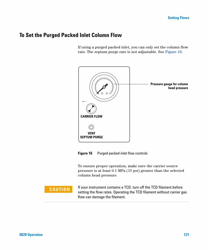
Setting Flows
To Set the Purged Packed Inlet Column Flow
6820 Operation
If using a purged packed inlet, you can only set the column flow rate. The septum purge rate is not adjustable. See Figure 16.
To ensure proper operation, make sure the carrier source pressure is at least 0.1 MPa (15 psi) greater than the selected column head pressure.
Figure 16 Purged packed inlet flow controls
VENTSEPTUM PURGE
CARRIER FLOW
Pressure gauge for columnhead pressure
If your instrument contains a TCD, turn off the TCD filament before
CAUTIONsetting the flow rates. Operating the TCD filament without carrier gas flow can damage the filament.121
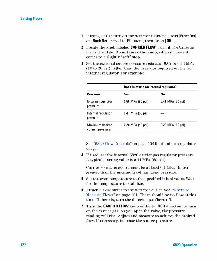
122
Setting Flows
1 If using a TCD, turn off the detector filament. Press [Front Det] or [Back Det], scroll to Filament, then press [Off].
2 Locate the knob labeled CARRIER FLOW. Turn it clockwise as far as it will go. Do not force the knob; when it closes it comes to a slightly “soft” stop.
3 Set the external source pressure regulator 0.07 to 0.14 MPa (10 to 20 psi) higher than the pressure required on the GC internal regulator. For example:
See “6820 Flow Controls” on page 104 for details on regulator usage.
4 If used, set the internal 6820 carrier gas regulator pressure. A typical starting value is 0.41 MPa (60 psi).
Carrier source pressure must be at least 0.1 MPa (15 psi) greater than the maximum column head pressure.
5 Set the oven temperature to the specified initial value. Wait for the temperature to stabilize.
6 Attach a flow meter to the detector outlet. See “Where to Measure Flows” on page 101. There should be no flow at this time. If there is, turn the detector gas flows off.
7 Turn the CARRIER FLOW knob in the ← INCR direction to turn on the carrier gas. As you open the valve, the pressure reading will rise. Adjust and measure to achieve the desired flow. If necessary, increase the source pressure.
Does inlet use an internal regulator?
Pressure Yes No
External regulator pressure
0.55 MPa (80 psi) 0.41 MPa (60 psi)
Internal regulator pressure
0.41 MPa (60 psi) —
Maximum desired column pressure
0.28 MPa (40 psi) 0.28 MPa (40 psi)
6820 Operation
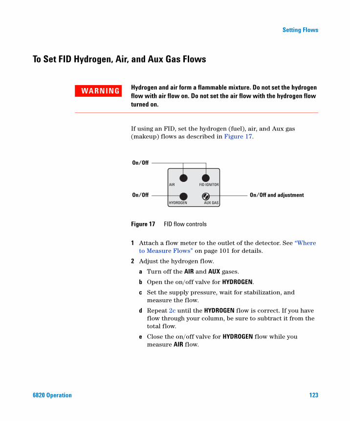
Setting Flows
To Set FID Hydrogen, Air, and Aux Gas Flows
6820 Operation
WARNING Hydrogen and air form a flammable mixture. Do not set the hydrogen flow with air flow on. Do not set the air flow with the hydrogen flow turned on.
If using an FID, set the hydrogen (fuel), air, and Aux gas (makeup) flows as described in Figure 17.
1 Attach a flow meter to the outlet of the detector. See “Where to Measure Flows” on page 101 for details.
2 Adjust the hydrogen flow.
a Turn off the AIR and AUX gases.
b Open the on/off valve for HYDROGEN.
c Set the supply pressure, wait for stabilization, and measure the flow.
d Repeat 2c until the HYDROGEN flow is correct. If you have flow through your column, be sure to subtract it from the total flow.
e Close the on/off valve for HYDROGEN flow while you measure AIR flow.
Figure 17 FID flow controls
AIR
HYDROGEN AUX GAS
FID IGNITOR
On/Off
On/Off and adjustmentOn/Off
123
124
Setting Flows
3 Adjust the AIR flow.
a Make sure the HYDROGEN and AUX GAS flows are turned off.
b Open the on/off valve for AIR.
c Set the supply pressure, wait for stabilization, and measure flow.
d Repeat step 3c until the AIR flow is correct. If you have flow through your column, subtract it from the total flow.
e Close the on/off valve for AIR.
4 If you are using packed columns, turn the AUX GAS off.
5 If you are using capillary columns, set the AUX GAS flow.
a Make sure the AIR and HYDROGEN flows are turned off.
b Open the on/off valve for the AUX GAS (makeup).
c Set the supply pressure for the AUX GAS to about 0.28 MPa (40 psi).
d Use a small screwdriver to turn the variable restrictor at the center of the FID AUX GAS knob as necessary to obtain the correct total flow (column + makeup).
If you cannot achieve the desired flow using the variable restrictor, re-adjust the supply pressure.
6820 Operation
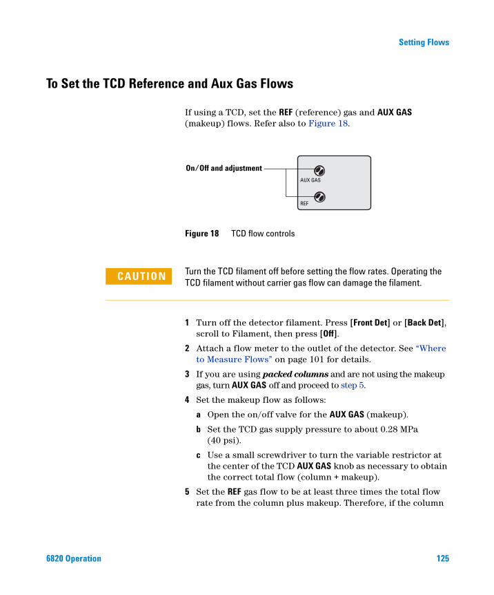
Setting Flows
To Set the TCD Reference and Aux Gas Flows
6820 Operation
If using a TCD, set the REF (reference) gas and AUX GAS (makeup) flows. Refer also to Figure 18.
Figure 18 TCD flow controls
REF
AUX GAS
On/Off and adjustment
CAUTION Turn the TCD filament off before setting the flow rates. Operating the TCD filament without carrier gas flow can damage the filament.
1 Turn off the detector filament. Press [Front Det] or [Back Det], scroll to Filament, then press [Off].
2 Attach a flow meter to the outlet of the detector. See “Where to Measure Flows” on page 101 for details.
3 If you are using packed columns and are not using the makeup gas, turn AUX GAS off and proceed to step 5.
4 Set the makeup flow as follows:
a Open the on/off valve for the AUX GAS (makeup).
b Set the TCD gas supply pressure to about 0.28 MPa (40 psi).
c Use a small screwdriver to turn the variable restrictor at the center of the TCD AUX GAS knob as necessary to obtain the correct total flow (column + makeup).
5 Set the REF gas flow to be at least three times the total flow rate from the column plus makeup. Therefore, if the column
125
126
Setting Flows
plus the makeup flow is 5 mL/min, the REF flow should equal 15 mL/min.
a Open the on/off valve for the REF gas.
b Use a small screwdriver to turn the variable restrictor at the center of the reference gas on/off valve as necessary to obtain the correct flow.
If you cannot achieve the desired flow using the variable restrictor, re-adjust the supply pressure.
6820 Operation
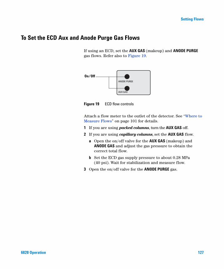
Setting Flows
To Set the ECD Aux and Anode Purge Gas Flows
6820 Operation
If using an ECD, set the AUX GAS (makeup) and ANODE PURGE gas flows. Refer also to Figure 19.
Attach a flow meter to the outlet of the detector. See “Where to Measure Flows” on page 101 for details.
1 If you are using packed columns, turn the AUX GAS off.
2 If you are using capillary columns, set the AUX GAS flow.
a Open the on/off valve for the AUX GAS (makeup) and ANODE GAS and adjust the gas pressure to obtain the correct total flow.
b Set the ECD gas supply pressure to about 0.28 MPa (40 psi). Wait for stabilization and measure flow.
3 Open the on/off valve for the ANODE PURGE gas.
Figure 19 ECD flow controls
AUX GAS
ANODE PURGE
On/Off
127
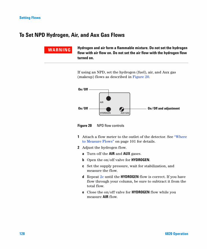
Setting Flows
To Set NPD Hydrogen, Air, and Aux Gas Flows
128
Hydrogen and air form a flammable mixture. Do not set the hydrogen
WARNINGflow with air flow on. Do not set the air flow with the hydrogen flow turned on.If using an NPD, set the hydrogen (fuel), air, and Aux gas (makeup) flows as described in Figure 20.
1 Attach a flow meter to the outlet of the detector. See “Where to Measure Flows” on page 101 for details.
2 Adjust the hydrogen flow.
a Turn off the AIR and AUX gases.
b Open the on/off valve for HYDROGEN.
c Set the supply pressure, wait for stabilization, and measure the flow.
d Repeat 2c until the HYDROGEN flow is correct. If you have flow through your column, be sure to subtract it from the total flow.
e Close the on/off valve for HYDROGEN flow while you measure AIR flow.
Figure 20 NPD flow controls
AIR
HYDROGEN AUX GAS
On/Off
On/Off and adjustmentOn/Off
6820 Operation
Setting Flows
6820 Operation
3 Adjust the AIR flow.
a Make sure the HYDROGEN and AUX GAS flows are turned off.
b Open the on/off valve for AIR.
c Set the supply pressure, wait for stabilization, and measure flow.
d Repeat step 3c until the AIR flow is correct. If you have flow through your column, subtract it from the total flow.
e Close the on/off valve for AIR.
4 If you are using packed columns, turn the AUX GAS off.
5 If you are using capillary columns, set the AUX GAS flow.
a Make sure the AIR and HYDROGEN flows are turned off.
b Open the on/off valve for the AUX GAS (makeup).
c Set the supply pressure for the AUX GAS to about 0.28 MPa (40 psi).
d Use a small screwdriver to turn the variable restrictor at the center of the AUX GAS knob as necessary to obtain the correct total flow (column + makeup).
If you cannot achieve the desired flow using the variable restrictor, re-adjust the supply pressure.
129
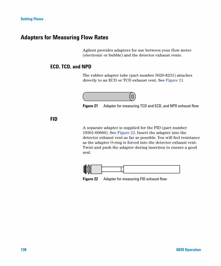
Setting Flows
Adapters for Measuring Flow Rates
130
Agilent provides adapters for use between your flow meter (electronic or bubble) and the detector exhaust vents.
ECD, TCD, and NPD
The rubber adapter tube (part number 5020-8231) attaches directly to an ECD or TCD exhaust vent. See Figure 21.
Figure 21 Adapter for measuring TCD and ECD, and NPD exhaust flow
FID
A separate adapter is supplied for the FID (part number 19301-60660). See Figure 22. Insert the adapter into the detector exhaust vent as far as possible. You will feel resistance as the adapter O-ring is forced into the detector exhaust vent. Twist and push the adapter during insertion to ensure a good seal.
Figure 22 Adapter for measuring FID exhaust flow
6820 Operation
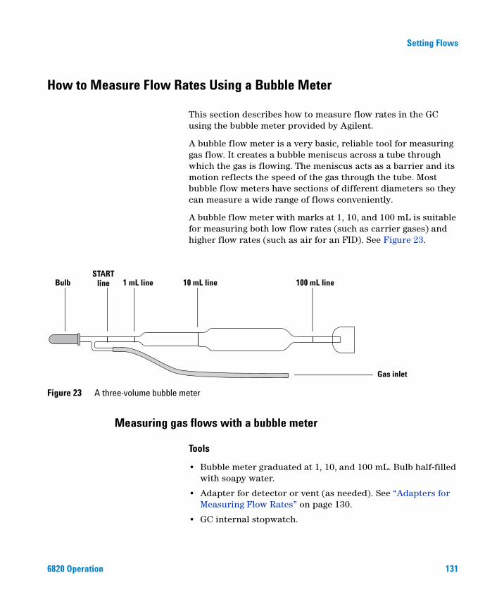
Setting Flows
How to Measure Flow Rates Using a Bubble Meter
6820 Operation
This section describes how to measure flow rates in the GC using the bubble meter provided by Agilent.
A bubble flow meter is a very basic, reliable tool for measuring gas flow. It creates a bubble meniscus across a tube through which the gas is flowing. The meniscus acts as a barrier and its motion reflects the speed of the gas through the tube. Most bubble flow meters have sections of different diameters so they can measure a wide range of flows conveniently.
A bubble flow meter with marks at 1, 10, and 100 mL is suitable for measuring both low flow rates (such as carrier gases) and higher flow rates (such as air for an FID). See Figure 23.
Measuring gas flows with a bubble meter
Figure 23 A three-volume bubble meter
Bulb 100 mL line
Gas inlet
10 mL line1 mL lineSTART
line
Tools
• Bubble meter graduated at 1, 10, and 100 mL. Bulb half-filled with soapy water.
• Adapter for detector or vent (as needed). See “Adapters for Measuring Flow Rates” on page 130.
• GC internal stopwatch.
131
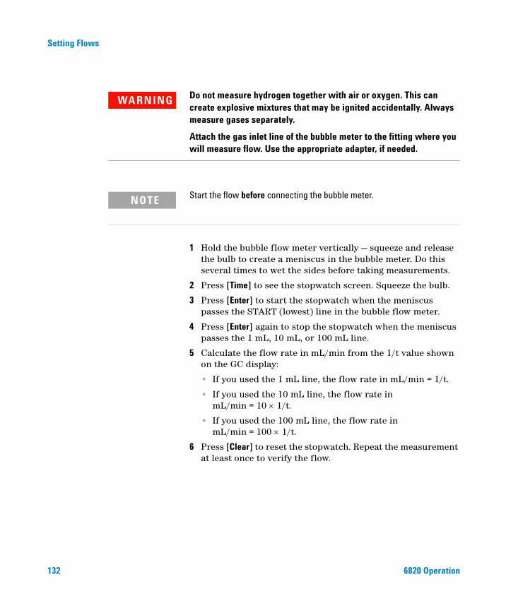
132
Setting Flows
WARNING Do not measure hydrogen together with air or oxygen. This can create explosive mixtures that may be ignited accidentally. Always measure gases separately.
Attach the gas inlet line of the bubble meter to the fitting where you will measure flow. Use the appropriate adapter, if needed.
Start the flow before connecting the bubble meter.
NOTE1 Hold the bubble flow meter vertically — squeeze and release the bulb to create a meniscus in the bubble meter. Do this several times to wet the sides before taking measurements.
2 Press [Time] to see the stopwatch screen. Squeeze the bulb.
3 Press [Enter] to start the stopwatch when the meniscus passes the START (lowest) line in the bubble flow meter.
4 Press [Enter] again to stop the stopwatch when the meniscus passes the 1 mL, 10 mL, or 100 mL line.
5 Calculate the flow rate in mL/min from the 1/t value shown on the GC display:
• If you used the 1 mL line, the flow rate in mL/min = 1/t.
• If you used the 10 mL line, the flow rate in mL/min = 10 × 1/t.
• If you used the 100 mL line, the flow rate in mL/min = 100 × 1/t.
6 Press [Clear] to reset the stopwatch. Repeat the measurement at least once to verify the flow.
6820 Operation
Agilent 6820 Gas ChromatographOperation
6Running Samples
Overview 134
Prepare the GC to Run Samples 135
Run a Sample Using Manual Injection 136
Run a Sample Using a Sampling Valve 138
Ignite the FID flame 140
Related Topics
Developing MethodsAdditional Information for Method Developers
This section outlines the basic steps for using the 6820 Gas Chromatograph (GC) to acquire experimental data when you are not using Cerity Chemical or other Agilent data system. It describes how to use some of the 6820’s features to best advantage, and provides an operating framework that can be adapted to each user’s needs.
133Agilent Technologies
Running Samples
Overview
134
There are three basic operating procedures for the 6820 when used in standalone mode:
• ”Prepare the GC to Run Samples” on page 135
• ”Run a Sample Using Manual Injection” on page 136
• ”Run a Sample Using a Sampling Valve” on page 138
If your GC uses an injection technique other than either manual syringe injection or sampling valve injection, refer to the operating information that came with your hardware for information about how the above procedures should be adapted.
6820 Operation
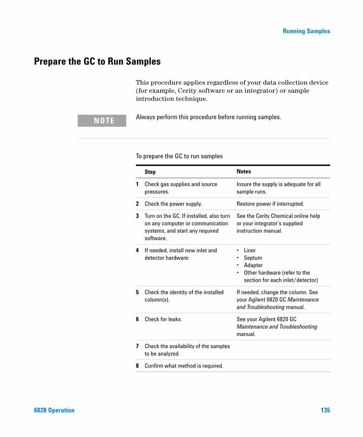
Running Samples
Prepare the GC to Run Samples
6820 Operation
This procedure applies regardless of your data collection device (for example, Cerity software or an integrator) or sample introduction technique.
Always perform this procedure before running samples.
NOTETo prepare the GC to run samples
Step Notes
1 Check gas supplies and source pressures.
Insure the supply is adequate for all sample runs.
2 Check the power supply. Restore power if interrupted.
3 Turn on the GC. If installed, also turn on any computer or communication systems, and start any required software.
See the Cerity Chemical online help or your integrator’s supplied instruction manual.
4 If needed, install new inlet and detector hardware:
• Liner• Septum• Adapter• Other hardware (refer to the
section for each inlet/detector)
5 Check the identity of the installed column(s).
If needed, change the column. See your Agilent 6820 GC Maintenance and Troubleshooting manual.
6 Check for leaks. See your Agilent 6820 GC Maintenance and Troubleshooting manual.
7 Check the availability of the samples to be analyzed.
8 Confirm what method is required.
135
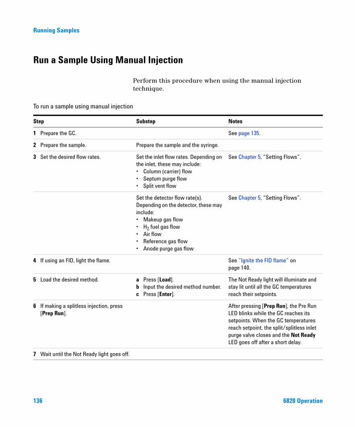
Running Samples
Run a Sample Using Manual Injection
136
Perform this procedure when using the manual injection technique.
n
To run a sample using manual injectioStep Substep Notes
1 Prepare the GC. See page 135.
2 Prepare the sample. Prepare the sample and the syringe.
3 Set the desired flow rates. Set the inlet flow rates. Depending on the inlet, these may include:• Column (carrier) flow• Septum purge flow• Split vent flow
See Chapter 5, “Setting Flows”.
Set the detector flow rate(s). Depending on the detector, these may include:• Makeup gas flow• H2 fuel gas flow• Air flow• Reference gas flow• Anode purge gas flow
See Chapter 5, “Setting Flows”.
4 If using an FID, light the flame. See ”Ignite the FID flame” on page 140.
5 Load the desired method. a Press [Load]. b Input the desired method number.c Press [Enter].
The Not Ready light will illuminate and stay lit until all the GC temperatures reach their setpoints.
6 If making a splitless injection, press [Prep Run].
After pressing [Prep Run], the Pre Run LED blinks while the GC reaches its setpoints. When the GC temperatures reach setpoint, the split/splitless inlet purge valve closes and the Not Ready LED goes off after a short delay.
7 Wait until the Not Ready light goes off.
6820 Operation
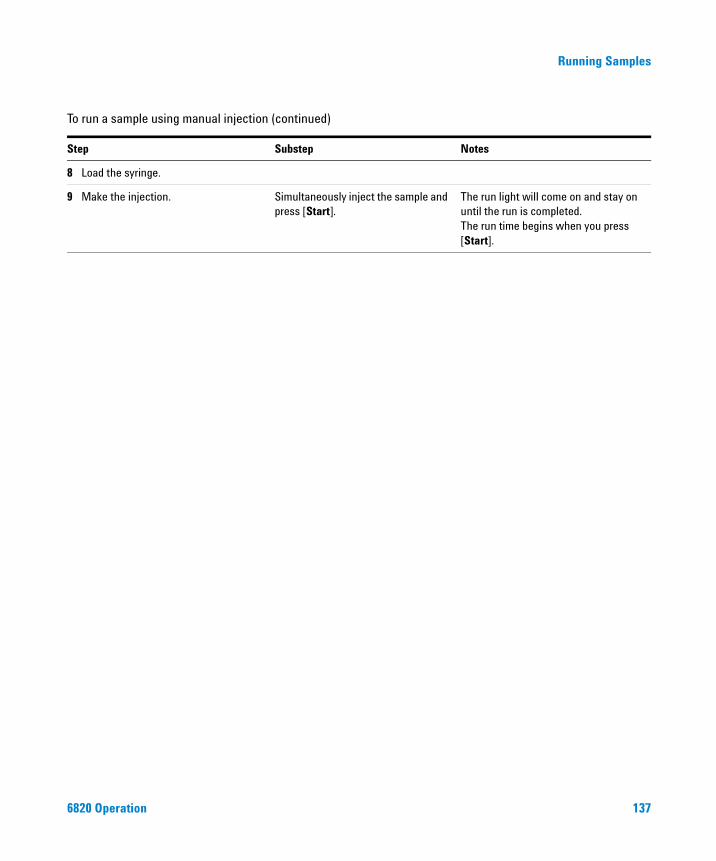
Running Samples
8 Load the syringe.
9 Make the injection. Simultaneously inject the sample and press [Start].
The run light will come on and stay on until the run is completed.The run time begins when you press [Start].
To run a sample using manual injection (continued)
Step Substep Notes
6820 Operation 137
Running Samples
Run a Sample Using a Sampling Valve
138
Perform this procedure when using a gas or liquid sampling valve as the injection source.
e
To run a sample using a sampling valvStep Substep Notes
1 Prepare the GC. See page 135.
2 Prepare the sample. Insure that the sample flow to the valve is on.
3 Set the desired flow rates. Set the inlet flow rates. Depending on the inlet, these may include:• Column (carrier) flow• Septum purge flow• Split vent flow
See Chapter 5, “Setting Flows”.
Set the detector flow rate(s). Depending on the detector, these may include:• Column (carrier) flow• Makeup gas flow• H2 fuel gas flow• Air flow• Reference gas flow• Anode purge gas flow
See Chapter 5, “Setting Flows”.
4 If using an FID, light the flame. See ”Ignite the FID flame” on page 140.
5 Load the desired method. a Press [Load]. b Input the desired method number.c Press [Enter].
The Not Ready light will illuminate and stay lit until all the GC temperatures reach their setpoints.
6820 Operation
Running Samples
6 Wait until the Not Ready light goes off.
7 Make the injection. If using GC control, and the method does NOT include Run Table events for valve control:a Press [Valve#].b Select the correct sampling valve, then
press [On].
If using GC control, and the method INCLUDES Run Table events for valve control:Press [Start].
For more information see:• ”Run Time Programming: Using
Run Time Events” on page 153• ”Controlling the Valves” on page 90• ”Valves” on page 190
To run a sample using a sampling valve (continued)
Step Substep Notes
6820 Operation 139

Running Samples
Ignite the FID flame
140
To light the FID flame:
1 Set the hydrogen and air flows. See ”To Set FID Hydrogen, Air, and Aux Gas Flows” on page 123.
2 Turn the HYDROGEN and AIR flows on.
3 Press [Front Det] or [Back Det] to see the detector output.
4 Press FID IGNITOR on the FID module.
The signal typically increases to 5 to 20 pA after ignition.
Verify that the flame is lit by holding a cold, shiny surface, such as a mirror or chrome-plated wrench, over the collector exit. Steady condensation indicates that the flame is lit.
If the flame does not light after several tries, see your Agilent 6820 GC Maintenance and Troubleshooting manual on the 6820 User Information CD.
6820 Operation
Agilent 6820 Gas ChromatographOperation
7Scheduling Clock Time Events
Overview 142
Types of clock table events 142
To program clock time events 144
To add an event to the clock table 145
To edit a clock time event 145
To delete a clock time event 146
To delete the entire clock table 146
Clock time events can be used to program certain setting changes to occur during a day based on the 24-hour clock. You can program up to 25 clock time events. This collection of events is called a clock table, and the GC executes it every day. The 6820 has only one clock table.
141Agilent Technologies
Scheduling Clock Time Events
Overview
142
The clock table is useful for valve control, loading methods, and initiating blank runs. Some examples of clock table use are:
• Load a method before you get to work in the morning, so the GC is ready for use when you arrive
• Load and run a method at the end of the work day, after you go home, to clean the column
• Load a method to reduce column temperature after the work day ends, then load the operating method in the morning before you arrive at work
• Perform a column compensation run
Program clock time events using a 24-hour clock. Thus, an event programmed to occur at 14:35 hours will occur at 2:35 in the afternoon.
Clock table events and sample runs
A running analysis has precedence over any scheduled clock table events. Clock table events that conflict with an ongoing sample run are skipped for that day.
Types of clock table events
Table 20 lists all possible clock time events. The list available for your instrument will depend on the hardware installed.
Table 20 Available clock time events
Event Notes
Valve Sets valve parameters
Load method Loads the appropriate method
Blank run Starts a blank run
Prep run Same as pressing prep run key at time event fires
6820 Operation
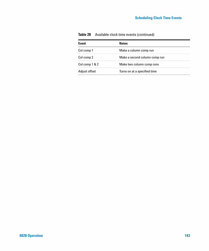
Scheduling Clock Time Events
6820 Operation
Col comp 1 Make a column comp run
Col comp 2 Make a second column comp run
Col comp 1 & 2 Make two column comp runs
Adjust offset Turns on at a specified time
Table 20 Available clock time events (continued)
Event Notes
143
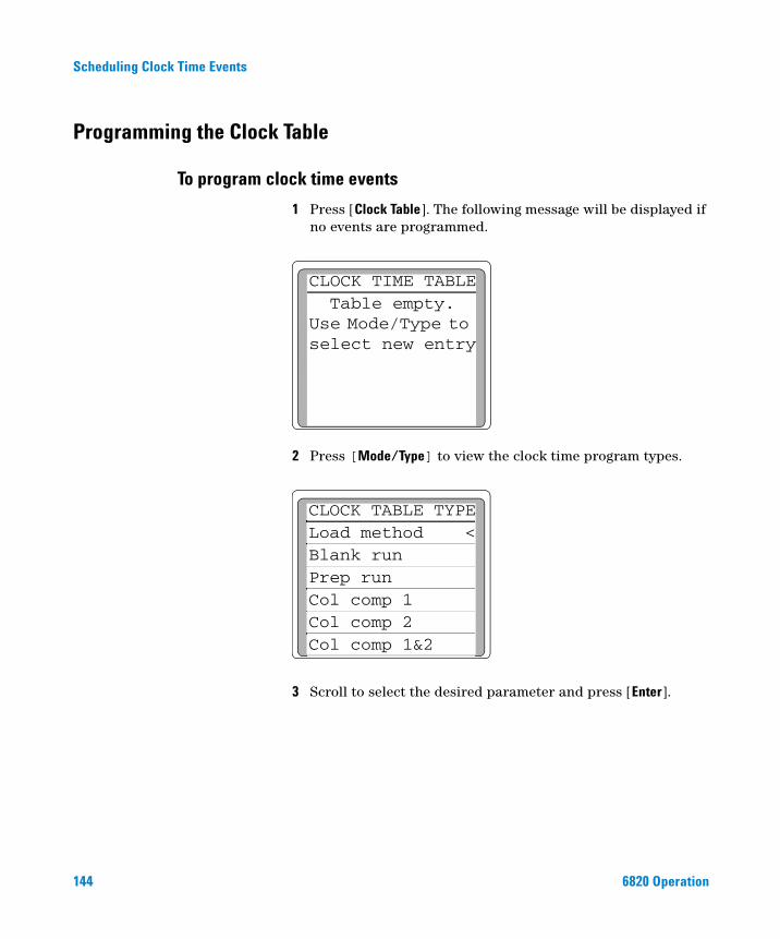
Scheduling Clock Time Events
Programming the Clock Table
To program clock time events
144
1 Press [Clock Table]. The following message will be displayed if no events are programmed.
2 Press [Mode/Type] to view the clock time program types.
3 Scroll to select the desired parameter and press [Enter].
CLOCK TIME TABLETable empty.
Use Mode/Type to select new entry
CLOCK TABLE TYPELoad method <Blank runPrep runCol comp 1Col comp 2Col comp 1&2
6820 Operation
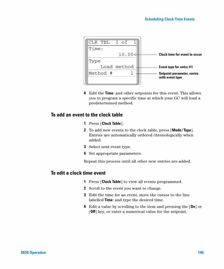
Scheduling Clock Time Events
6820 Operation
4 Edit the Time: and other setpoints for this event. This allows you to program a specific time at which your GC will load a predetermined method.
CLK TBL 1 of 1Time:
10.00<Type
Load method Method # 1
Clock time for event to occur
Event type for entry #1
Setpoint parameter, varies with event type
To add an event to the clock table
1 Press [Clock Table].
2 To add new events to the clock table, press [Mode/Type]. Entries are automatically ordered chronologically when added.
3 Select next event type.
4 Set appropriate parameters.
Repeat this process until all other new entries are added.
To edit a clock time event
1 Press [Clock Table] to view all events programmed.
2 Scroll to the event you want to change.
3 Edit the time for an event, move the cursor to the line labelled Time: and type the desired time.
4 Edit a value by scrolling to the item and pressing the [On] or [Off] key, or enter a numerical value for the setpoint.
145
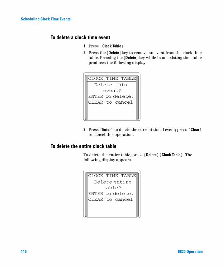
Scheduling Clock Time Events
To delete a clock time event
146
1 Press [Clock Table].
2 Press the [Delete] key to remove an event from the clock time table. Pressing the [Delete] key while in an existing time table produces the following display:
3 Press [Enter] to delete the current timed event; press [Clear] to cancel this operation.
CLOCK TIME TABLEDelete this
event?ENTER to delete, CLEAR to cancel
To delete the entire clock table
To delete the entire table, press [Delete][Clock Table]. The following display appears.
CLOCK TIME TABLEDelete entire
table?ENTER to delete, CLEAR to cancel
6820 Operation
Agilent 6820 Gas ChromatographOperation
8Developing Methods
What is a Method? 148
Types of methods 148
How the GC uses the active method 148
What Can You Do With It? 149
Creating Methods 150
Method creation tips 152
Initial flow rates 152
Run Time Programming: Using Run Time Events 153
To program run time events 155
To add events to the run table 156
To edit events in the run table 156
To delete run time events 157
Default Method Parameters 158
To load the default parameters 158
Method Mismatch 159
User-entered configuration changes 159
Hardware configuration changes 160
Related topics
Chapter 2, “Strategy for Using the 6820”This section describes what a 6820 method is, how methods are used by the 6820, and how to create them. It then describes the advanced method features associated with the Run Table, how to load default parameters for a method, and how to interpret method mismatch errors.
147Agilent Technologies
Developing Methods
What is a Method?
148
A method is a collection of parameters required to run a single sample on the 6820 GC. Methods make it possible to restore the instrument to a desired setup without reentering all the parameters.
Types of methods
There are three kinds of methods:
• The active method: the settings that you are presently using.
• Stored method: one of the nine methods that can be stored in the GC.
• The default method: a set of default parameters for the GC. It can be reloaded at any time. The GC maintains the default method separately from the stored method.
How the GC uses the active method
The GC keeps the active method separate from the stored methods. This allows you to change, test, or use method settings without losing stored information.
When you turn the instrument off, the GC saves the active method and reloads it automatically when you turn the instrument back on. However, if the hardware is changed while the instrument is turned off, it may not be possible to restore all parameters in the method, resulting in an error condition.
When you load a stored method, that stored method becomes the active method. It replaces whatever settings had been in use.
6820 Operation
Developing Methods
What Can You Do With It?
6820 Operation
Methods can be created, loaded, stored, modified, and deleted. The GC can store up to nine (9) user-defined methods.
• To load, store, or delete a method, see “The method keys: [Load], [Store], and [Method]” on page 64.
• To create a method, modify the active method with the new parameters, then store the method as one of the nine stored methods. See “Creating Methods” on page 150.
• To modify a method:
1 Load it.
2 Make the desired changes to the settings.
3 Store it to the same method number.
In addition to basic instrument control of temperatures and run times, the method can also perform run time events. Run time events are functions or settings programmed to occur at a specified time during the run. They may include:
• Modifying the signal sent to the data collection device or computer
• Determining or changing the signal type
• Switching (rotating) valves during the run
• Setting the signal level
First, we will discuss how to create a method. Next we will discuss how to use run time events and how to revert to the default method. Then we will describe what happens when a loaded method does not match current GC configuration.
149
Developing Methods
Creating Methods
150
To create a storable 6820 method, first, determine what settings you will need to enter and also what hardware (inlet type, liner type, column, carrier gas, etc.) will be required to analyze the sample. Once you know these, you can create a 6820 method to store these conditions and configuration so they can be recalled and used whenever needed.
The procedure below lists all possible settings you may need to consider when creating a method. The list of parameters for your instrument depends on the hardware installed in it. For more information on what values to use, see Chapter 10, “Additional Information for Method Developers”.
In most cases, you can perform steps 2 through 9 in any order. Always configure your instrument first so that the settings you need will be available.
Overview of creating a method
Step Action Notes
1 Check instrument configuration. a Install hardware if needed.b Configure the instrument if needed.
Verify correct hardware components are installed. See the Agilent 6820 GC Maintenance and Troubleshooting manual and “Configure the Instrument” on page 72.
2 If using a valve, configure it. a Press [Config], select Valve #, and input the valve number to configure.
b Configure the valve parameters.
Sampling valves include a minimum sampling time and the dwell time for injection.Switching valves include an on/off setting.See “Configure the valves” on page 74 and “Valves” on page 190.
3 If desired, load a similar method. a Press [Load].b Enter the method number, then press
[Enter].
If another method contains similar settings, you can load it if desired.
6820 Operation

Developing Methods
4 Set oven parameters. Press [Oven] and enter values as needed. Set the temperature and run time. If needed, also program oven temperature ramps. See “Configure the oven” on page 72.”
5 If using an inlet, set inlet parameters.
Press [Front Inlet] or [Back Inlet] and enter values as needed.
This can include temperature as well as other parameters, such as inlet mode. Choices depend on the analysis and the inlet type. See “Setting the Inlet Parameters” on page 82.
6 Set detector parameters. Press [Front Det] or [Back Det] and enter values as needed.
• Set the temperature• Enable the detector (turn
electrometer or filament on)• Set the detector data rate (if
available)• When using FID, you must light the
flame at run time.See “Setting the Detector Parameters” on page 84.
7 Set auxiliary zone temperatures, if needed.
a Press [Aux#], and input the number of the zone (1 or 2).
b Input the temperature and press [Enter].
For example, set the heated valve box temperature. See “Configure the Aux thermal zones” on page 74.
8 Set signal parameters as needed. a Press [Signal 1] or [Signal 2]. b Scroll to Type and press [Mode/Type].c Scroll to the appropriate signal output
and press [Enter] to select it.
Signal parameters can include scaling factors and signal type. See “Signal Handling” on page 198.
9 Set run table events, if needed. a Press [Run Table], [Mode/Type].b Scroll to the event type to be
programmed and press [Enter].c Choose the appropriate signal when
prompted.d Enter values for the Time and Setpoint
parameters.
If using a sampling or switching valve, you can use the run table to control it. “Run Time Programming: Using Run Time Events” on page 153 for details about Run Table events.
10 Store these parameters as a method.
Press [Store] and input a method number.
Overview of creating a method (continued)
Step Action Notes
6820 Operation 151
Developing Methods
Method creation tips
152
When creating or modifying a method, keep the following hints in mind:
• The available settings depend on what equipment is present. While the GC can sense many of its components, some information (such as what type of inlet is installed) must be entered by the user. Always configure (define) instrument elements before trying to use them.
• Use the [Config] key routinely to verify that the configuration is what you believe it to be.
• Use the [Info] key for help with setpoint ranges, next action to perform, and other advice.
• Many settings require that you select from a list of choices. The [Mode/Type] key opens these lists. If a setting seems to call for an entry other than a number or [On] or [Off], try [Mode/Type] to see if there is an underlying menu.
Initial flow rates
Refer to the Agilent Fundamentals of GC document (part number G1176-90000 in English, G1176-97000 in Chinese) for information about starting column flow rates.
For information about initial flow rates for detectors, see:
“Selecting FID flow rates and temperature” on page 174
“Selecting TCD flow rates and temperature” on page 179
“Selecting ECD flow rates and temperatures” on page 183
“Selecting NPD flow rates and temperature” on page 188
6820 Operation
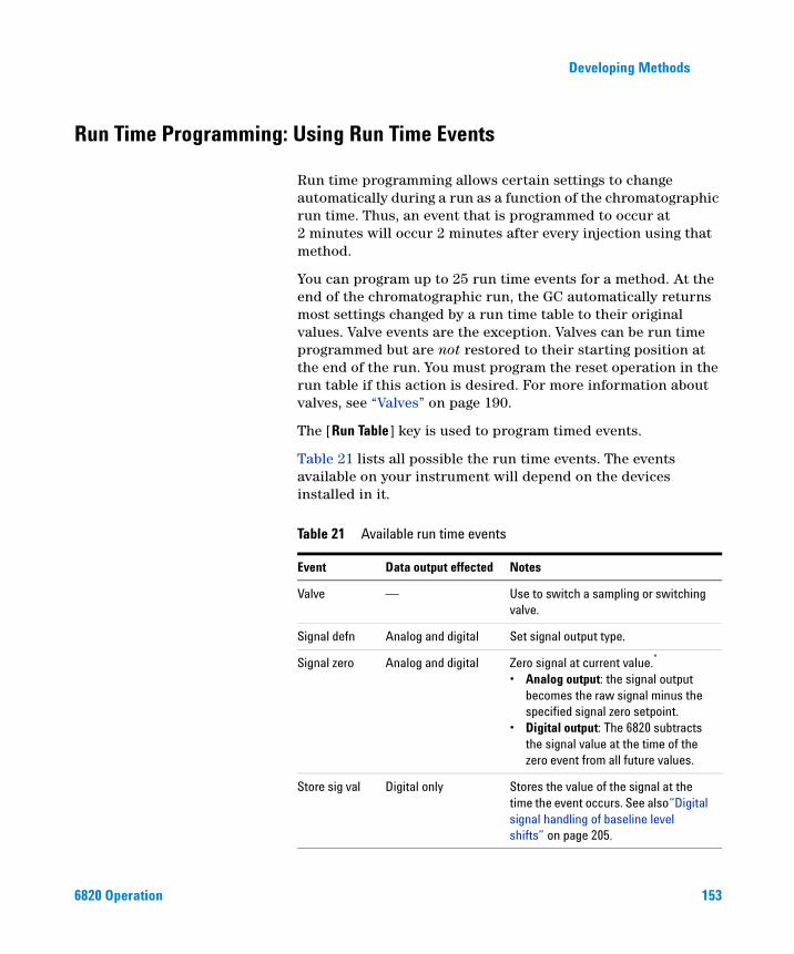
Developing Methods
Run Time Programming: Using Run Time Events
6820 Operation
Run time programming allows certain settings to change automatically during a run as a function of the chromatographic run time. Thus, an event that is programmed to occur at 2 minutes will occur 2 minutes after every injection using that method.
You can program up to 25 run time events for a method. At the end of the chromatographic run, the GC automatically returns most settings changed by a run time table to their original values. Valve events are the exception. Valves can be run time programmed but are not restored to their starting position at the end of the run. You must program the reset operation in the run table if this action is desired. For more information about valves, see “Valves” on page 190.
The [Run Table] key is used to program timed events.
Table 21 lists all possible the run time events. The events available on your instrument will depend on the devices installed in it.
Table 21 Available run time events
Event Data output effected Notes
Valve — Use to switch a sampling or switching valve.
Signal defn Analog and digital Set signal output type.
Signal zero Analog and digital Zero signal at current value.*
• Analog output: the signal output becomes the raw signal minus the specified signal zero setpoint.
• Digital output: The 6820 subtracts the signal value at the time of the zero event from all future values.
Store sig val Digital only Stores the value of the signal at the time the event occurs. See also“Digital signal handling of baseline level shifts” on page 205.
153
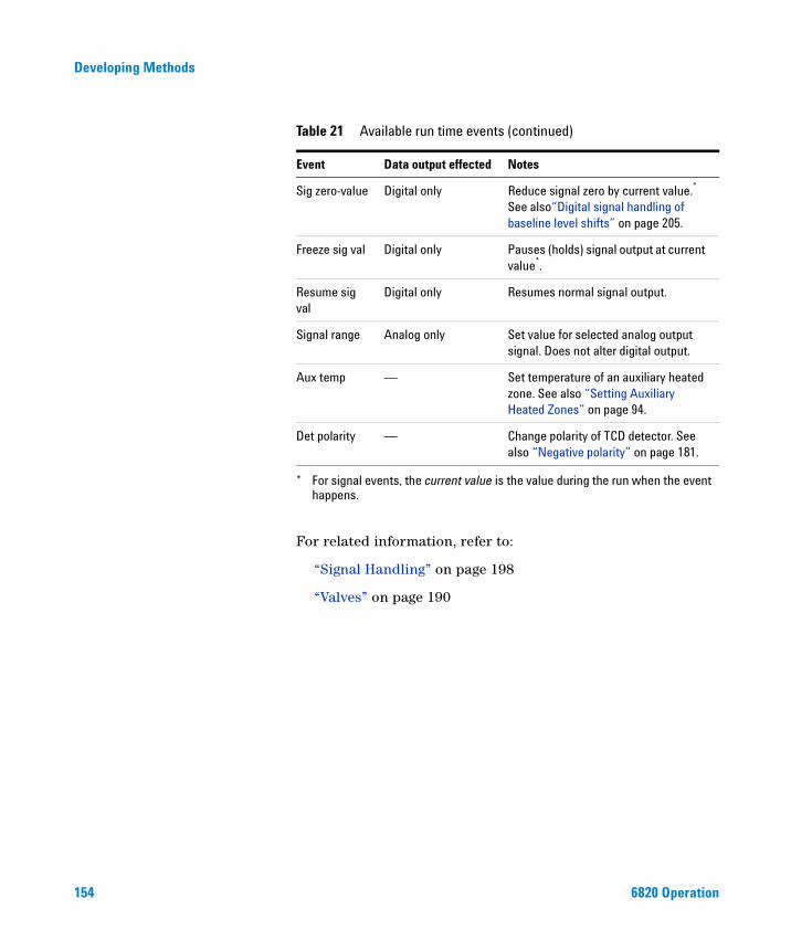
154
Developing Methods
For related information, refer to:
“Signal Handling” on page 198
“Valves” on page 190
Sig zero-value Digital only Reduce signal zero by current value.* See also“Digital signal handling of baseline level shifts” on page 205.
Freeze sig val Digital only Pauses (holds) signal output at current value*.
Resume sig val
Digital only Resumes normal signal output.
Signal range Analog only Set value for selected analog output signal. Does not alter digital output.
Aux temp — Set temperature of an auxiliary heated zone. See also “Setting Auxiliary Heated Zones” on page 94.
Det polarity — Change polarity of TCD detector. See also “Negative polarity” on page 181.
* For signal events, the current value is the value during the run when the event happens.
Table 21 Available run time events (continued)
Event Data output effected Notes
6820 Operation
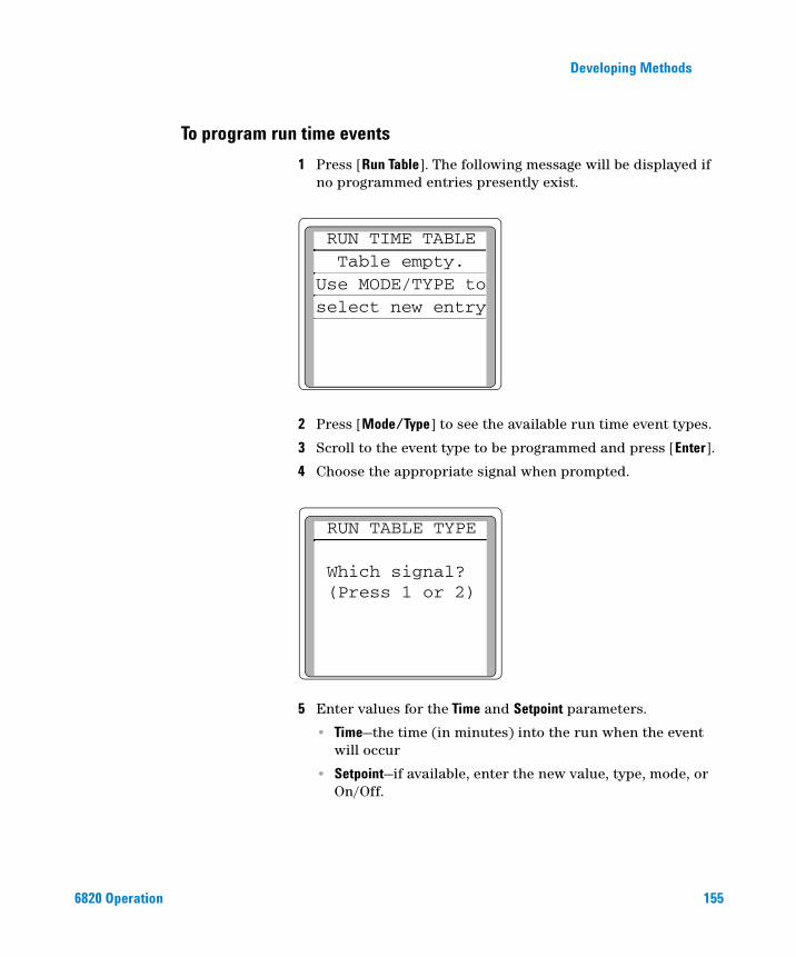
Developing Methods
To program run time events
6820 Operation
1 Press [Run Table]. The following message will be displayed if no programmed entries presently exist.
2 Press [Mode/Type] to see the available run time event types.
3 Scroll to the event type to be programmed and press [Enter].
4 Choose the appropriate signal when prompted.
5 Enter values for the Time and Setpoint parameters.
• Time—the time (in minutes) into the run when the event will occur
• Setpoint—if available, enter the new value, type, mode, or On/Off.
RUN TIME TABLETable empty.
Use MODE/TYPE toselect new entry
RUN TABLE TYPE
Which signal?(Press 1 or 2)
155
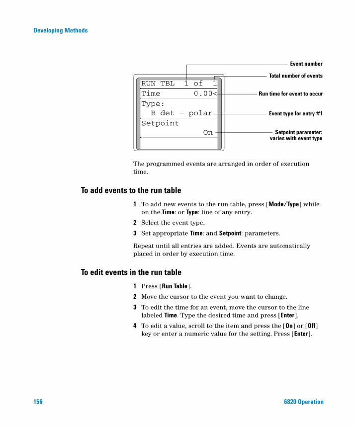
156
Developing Methods
The programmed events are arranged in order of execution time.
Run time for event to occur
Event type for entry #1
varies with event typeSetpoint parameter:
RUN TBL 1 of 1Time 0.00<Type:B det - polar
SetpointOn
Total number of events
Event number
To add events to the run table
1 To add new events to the run table, press [Mode/Type] while on the Time: or Type: line of any entry.
2 Select the event type.
3 Set appropriate Time: and Setpoint: parameters.
Repeat until all entries are added. Events are automatically placed in order by execution time.
To edit events in the run table
1 Press [Run Table].
2 Move the cursor to the event you want to change.
3 To edit the time for an event, move the cursor to the line labeled Time. Type the desired time and press [Enter].
4 To edit a value, scroll to the item and press the [On] or [Off] key or enter a numeric value for the setting. Press [Enter].
6820 Operation
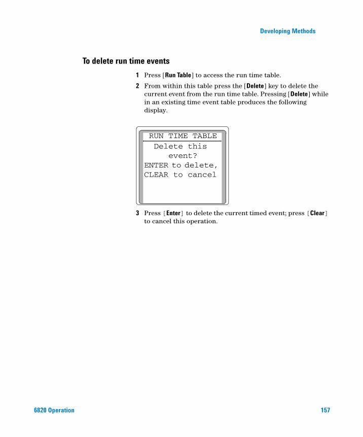
Developing Methods
To delete run time events
6820 Operation
1 Press [Run Table] to access the run time table.
2 From within this table press the [Delete] key to delete the current event from the run time table. Pressing [Delete] while in an existing time event table produces the following display.
3 Press [Enter] to delete the current timed event; press [Clear] to cancel this operation.
RUN TIME TABLEDelete this
event?ENTER to delete, CLEAR to cancel
157
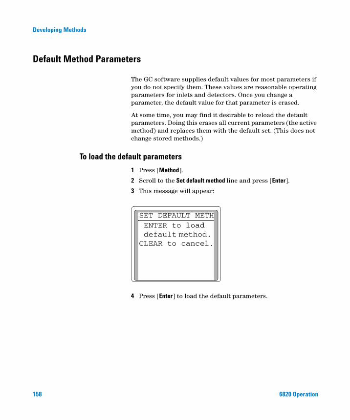
Developing Methods
Default Method Parameters
158
The GC software supplies default values for most parameters if you do not specify them. These values are reasonable operating parameters for inlets and detectors. Once you change a parameter, the default value for that parameter is erased.
At some time, you may find it desirable to reload the default parameters. Doing this erases all current parameters (the active method) and replaces them with the default set. (This does not change stored methods.)
To load the default parameters
1 Press [Method].
2 Scroll to the Set default method line and press [Enter].
3 This message will appear:
4 Press [Enter] to load the default parameters.
SET DEFAULT METHENTER to load default method. CLEAR to cancel.
6820 Operation
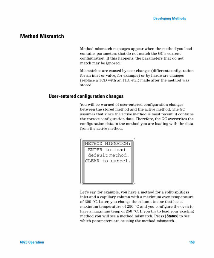
Developing Methods
Method Mismatch
6820 Operation
Method mismatch messages appear when the method you load contains parameters that do not match the GC’s current configuration. If this happens, the parameters that do not match may be ignored.
Mismatches are caused by user changes (different configuration for an inlet or valve, for example) or by hardware changes (replace a TCD with an FID, etc.) made after the method was stored.
User-entered configuration changes
You will be warned of user-entered configuration changes between the stored method and the active method. The GC assumes that since the active method is most recent, it contains the correct configuration data. Therefore, the GC overwrites the configuration data in the method you are loading with the data from the active method.
Let’s say, for example, you have a method for a split/splitless inlet and a capillary column with a maximum oven temperature of 300 °C. Later, you change the column to one that has a maximum temperature of 250 °C and you configure the oven to have a maximum temp of 250 °C. If you try to load your existing method you will see a method mismatch. Press [Status] to see which parameters are causing the method mismatch.
METHOD MISMATCH:ENTER to load default method. CLEAR to cancel.
159
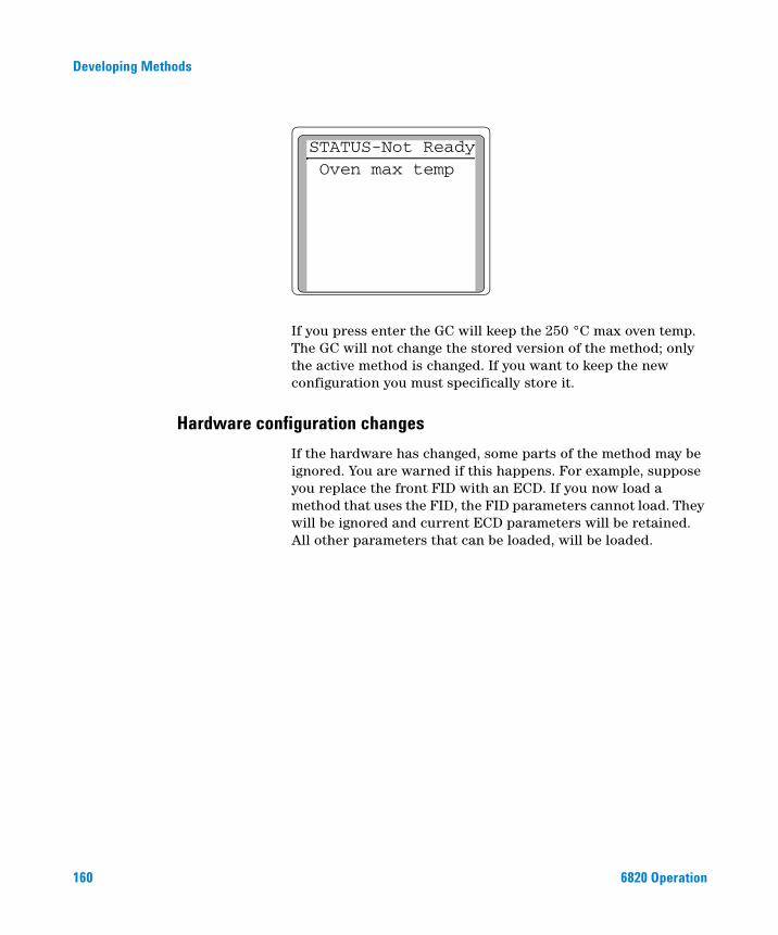
160
Developing Methods
If you press enter the GC will keep the 250 °C max oven temp. The GC will not change the stored version of the method; only the active method is changed. If you want to keep the new configuration you must specifically store it.
STATUS-Not ReadyOven max temp
Hardware configuration changes
If the hardware has changed, some parts of the method may be ignored. You are warned if this happens. For example, suppose you replace the front FID with an ECD. If you now load a method that uses the FID, the FID parameters cannot load. They will be ignored and current ECD parameters will be retained. All other parameters that can be loaded, will be loaded.
6820 Operation
Agilent 6820 Gas ChromatographOperation
9Shutting Down
Create Cerity Chemical shutdown methods 162
For less than 1 week 163
For more than 1 week 164
This section describes how to safely shut down the GC when not in use.
161Agilent Technologies
Shutting Down
Shutting Down the GC
162
In general, leave the GC power on when not in use. This is a good idea because:
• Above-ambient temperature plus carrier gas flow keep the column clean.
• Certain detectors may take some time to stabilize after they are turned off.
Leave the GC on between runs and overnight.
If you are using hydrogen gas, you should turn off the hydrogen flow to avoid the possibility of an unmonitored leak when the GC is not in use for long periods.
To avoid damage to the column, cool the oven before shutting off the
CAUTIONcarrier gas.If using a TCD, consider turning the filament off. If the gas supply runs out while the GC is unattended, the TCD filament can be damaged or destroyed.
Create Cerity Chemical shutdown methods
Using Cerity Chemical, create methods to facilitate GC shutdowns. Create one method for preparing the GC for complete shutdown (for example, for service or storage), and another method for conserving energy and supplies.
A conservation method should:
• Reduce detector, inlet, and oven temperatures to 150–200 °C to save energy and preserve the column. If using hydrogen carrier gas, turn off the oven.
• Turn off the TCD filament.
6820 Operation
Shutting Down
6820 Operation
A shutdown method should:
• Cool detector, inlet, and oven temperatures to ambient (25°C) to save energy and preserve the column. If using hydrogen carrier gas, turn off the oven.
• Turn off the TCD filament.
CAUTION If the gas flow is set too low, or if the carrier gas supply runs out while the GC is unattended, the TCD filament can be damaged or destroyed. Turn the filament Off when the TCD will not be used for extended periods.
For less than 1 week
CAUTION Failure to turn off the TCD filament before turning gas flows off can damage or destroy it. Turn the filament Off before shutting down the GC gas flows.
If you will not use the GC for up to approximately 1 week, conserve gases and energy as follows:
1 Reduce detector, inlet, and oven temperatures to 150–200 °C to save energy and preserve the column.
2 If using hydrogen carrier gas, cool then shut off the oven before shutting off the hydrogen gas supply.
3 Turn off corrosive or potentially hazardous gas flows, such as oxygen and hydrogen.
4 Reduce flows of carrier and makeup gases.
5 Turn the TCD filament off. Press [Front Det] or [Back Det], scroll to Filament, then press [Off].
Never leave flammable gas flows on if the GC will be unmonitored
WARNINGfor long periods of time. If a leak develops, the gas could create a fire or explosion hazard.163
164
Shutting Down
If the gas flow is set too low, or if the carrier gas supply runs out while
For more than 1 week
CAUTIONthe GC is unattended, the TCD filament can be damaged or destroyed. Turn the filament off when the TCD will not be used for extended periods.
Failure to turn off the TCD filament before turning gas flows off can
CAUTIONdamage or destroy it. Turn the filament off before shutting down the GC gas flows.1 If installed, turn off the TCD filament. Press [Front Det] or [Back Det], scroll to Filament, then press [Off].
2 Set all heated zones to ambient temperature and turn off the detector support gas flows. Leave the carrier gas flow on.
3 When the GC is cool, turn it off.
4 Turn off all gas and coolant supplies at their sources.
5 Remove the column and cap its ends to prevent contamination. Store the column in a cool, dry place.
6 To prevent contamination, cap the inlet and detector column fittings.
7 If gas connections are removed from the GC, cap the intake fittings on the back panel of the GC.
If desired, this is a good time to replace any traps. See the Maintenance and Troubleshooting manual on the 6820 User Information CD.
6820 Operation
Agilent 6820 Gas ChromatographOperation
10Additional Information for Method Developers
Inlets 166
Split/Splitless inlet 167
Purged packed inlet 168
Detectors 170
Flame Ionization Detector 172
Thermal Conductivity Detector 177
Electron Capture Detector 182
Nitrogen Phosphorus Detector 184
Valves 190
The Column Oven 194
Signal Handling 198
Instrument Supplies 207
This section provides important information about the devices available for use, as well as how to use them to best advantage. This information is intended as reference material for persons who are creating methods for the 6820.
165Agilent Technologies
Additional Information for Method Developers
Inlets
166
The GC Fundamentals manual included on the 6820 GC User Information
NOTECD-ROM contains details about how the inlets work and suggests starting values for your methods.The 6820 GC has two types of inlets available: the split/splitless (capillary) inlet and the purged packed inlet. Table 22 briefly describes the features of each type of inlet.
Septum purge and inlet vent flow rates
Table 22 An overview of inlets
Inlet Column Mode Sample concentration
Comments Sample to column
Split/Splitless Capillary Split
Splitless
High
Low
Very little
All
Purged packed PackedLarge capillary
n/an/a
AnyAny OK, if resolution
not critical
AllAll
Septum purge The septum purge line is near the septum where the sample is injected. A small amount of carrier gas exits through this line to sweep out any bleed. Each inlet has a different septum purge flow. The purge flow varies based on the carrier gas pressure, but is not adjustable.
Inlet vent The split/splitless inlet has an additional vent used for split flow. The flow from the inlet vent is not adjustable and varies depending on the column head pressure.
6820 Operation
Additional Information for Method Developers
Split/Splitless inlet
6820 Operation
Operating modes
The split/splitless inlet has two operating modes, split and splitless.
Split The sample is divided between the column and a vent flow. The split mode is generally used for major component analyses, and for high concentration samples when you can afford to lose most of the sample out the inlet vent. It is also used for samples that cannot be diluted.
Splitless The sample is not divided during the initial part of the injection. Most of it enters the column. A small amount is purged from the inlet to avoid excessive peak broadening and solvent tailing. At a specified time (determined by the purge time parameter in the method), the inlet's purge valve opens and excess (mostly solvent) vapors are swept out the inlet vent, while carrier gas maintains flow through the column. The splitless mode is generally used for trace analyses.
When developing a splitless injection method, adjust the purge time parameter to maximize sample response while eliminating as much of the solvent peak as possible.
Liners
Choose liners according to the type of injection you are doing—split or splitless. To choose the proper liner for a specific application, consider:
• Liner volume
• Liner treatments or deactivation to reduce sample degradation
• Any liner design features that might affect carrier gas flow through the inlet or sample vaporization
For more information on liners, see Maintenance and Troubleshooting on the User Information CD-ROM.
167
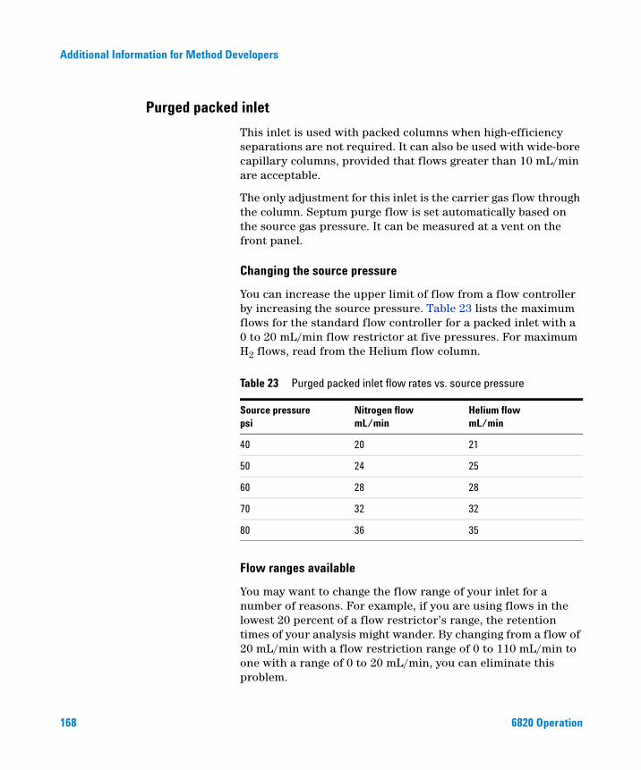
Additional Information for Method Developers
Purged packed inlet
168
This inlet is used with packed columns when high-efficiency separations are not required. It can also be used with wide-bore capillary columns, provided that flows greater than 10 mL/min are acceptable.
The only adjustment for this inlet is the carrier gas flow through the column. Septum purge flow is set automatically based on the source gas pressure. It can be measured at a vent on the front panel.
Changing the source pressure
You can increase the upper limit of flow from a flow controller by increasing the source pressure. Table 23 lists the maximum flows for the standard flow controller for a packed inlet with a 0 to 20 mL/min flow restrictor at five pressures. For maximum H2 flows, read from the Helium flow column.
Flow ranges available
You may want to change the flow range of your inlet for a number of reasons. For example, if you are using flows in the lowest 20 percent of a flow restrictor’s range, the retention times of your analysis might wander. By changing from a flow of 20 mL/min with a flow restriction range of 0 to 110 mL/min to one with a range of 0 to 20 mL/min, you can eliminate this problem.
Table 23 Purged packed inlet flow rates vs. source pressure
Source pressurepsi
Nitrogen flowmL/min
Helium flowmL/min
40 20 21
50 24 25
60 28 28
70 32 32
80 36 35
6820 Operation
Additional Information for Method Developers
6820 Operation
You can change the flow ranges in packed inlets by either:
• Changing the source pressure, or
• Changing the flow restrictor in the flow controller.
Changing the flow restrictor
For available restrictors and the replacement procedure, refer to the Agilent 6820 GC Service manual.
169
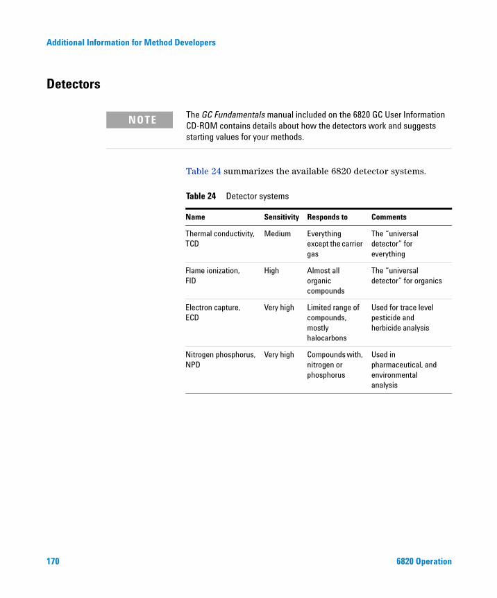
Additional Information for Method Developers
Detectors
170
The GC Fundamentals manual included on the 6820 GC User Information
NOTECD-ROM contains details about how the detectors work and suggests starting values for your methods.Table 24 summarizes the available 6820 detector systems.
Table 24 Detector systems
Name Sensitivity Responds to Comments
Thermal conductivity,TCD
Medium Everything except the carrier gas
The “universal detector” for everything
Flame ionization,FID
High Almost all organic compounds
The “universal detector” for organics
Electron capture,ECD
Very high Limited range of compounds, mostly halocarbons
Used for trace level pesticide and herbicide analysis
Nitrogen phosphorus,NPD
Very high Compounds with, nitrogen or phosphorus
Used in pharmaceutical, and environmental analysis
6820 Operation
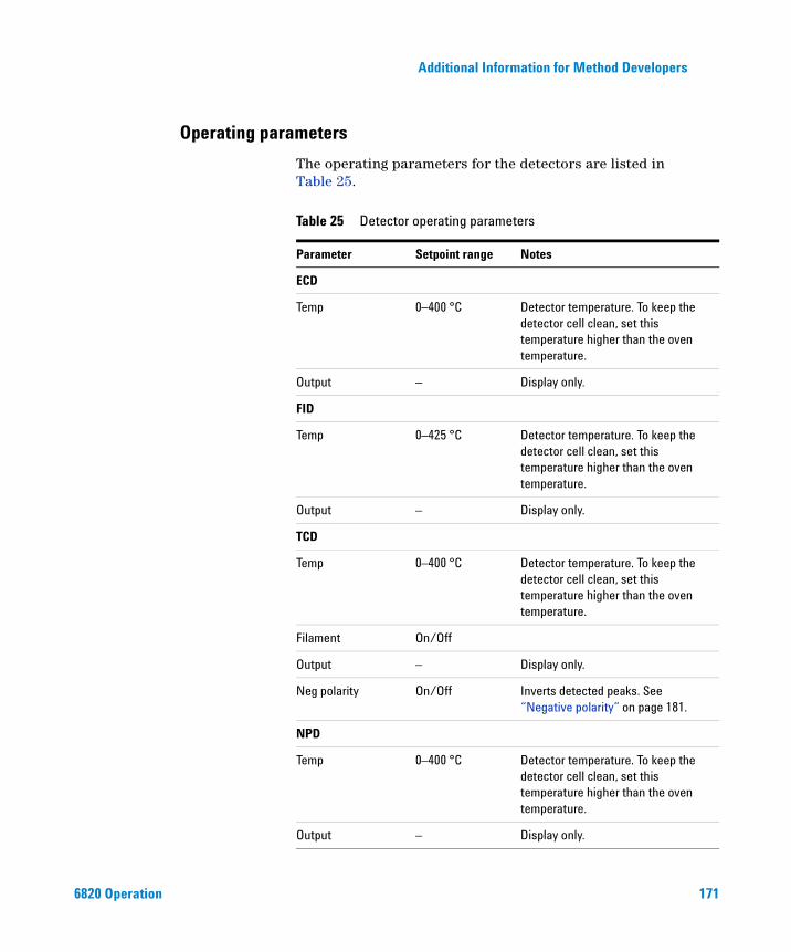
Additional Information for Method Developers
Operating parameters
6820 Operation
The operating parameters for the detectors are listed in Table 25.
Table 25 Detector operating parameters
Parameter Setpoint range Notes
ECD
Temp 0–400 °C Detector temperature. To keep the detector cell clean, set this temperature higher than the oven temperature.
Output – Display only.
FID
Temp 0–425 °C Detector temperature. To keep the detector cell clean, set this temperature higher than the oven temperature.
Output – Display only.
TCD
Temp 0–400 °C Detector temperature. To keep the detector cell clean, set this temperature higher than the oven temperature.
Filament On/Off
Output – Display only.
Neg polarity On/Off Inverts detected peaks. See “Negative polarity” on page 181.
NPD
Temp 0–400 °C Detector temperature. To keep the detector cell clean, set this temperature higher than the oven temperature.
Output – Display only.
171
172
Additional Information for Method Developers
Makeup gas flow
Makeup gas enters the detector close to the end of the column. Its purpose is to speed the peaks through the detector — especially with capillary columns — so that the peak separation achieved by the column is not lost through remixing in the detector.
Adjust offset 10–99 pA Suggested operating range is 30 to 40 pA
Equib time 0–999.9 minutes Recommended is 0.0 minutes;Default is 0.0 minutes
Bead voltage 0–4.095 V
Table 25 Detector operating parameters (continued)
Parameter Setpoint range Notes
Flame Ionization Detector
The Flame Ionization Detector passes sample and carrier gas from the column through a hydrogen-air flame. The hydrogen-air flame alone creates few ions, but when an organic compound is burned there is an increase in ions produced. A polarizing voltage attracts these ions to a collector located near the flame. The current produced is proportional to the amount of sample being burned. This current is sensed by an electrometer, converted to digital form, and sent to an output device.
Conditions for igniting the flame
Before igniting the flame, or if experiencing problems in lighting the flame, check the following:
• Make sure the hydrogen and air gases are turned on and that the flow rates are high enough for the flame to ignite. See Table 26 on page 174.
6820 Operation
Additional Information for Method Developers
6820 Operation
• Check that the right type of jet is installed for the column you are using. Jet types are listed in the Agilent 6820 GC Maintenance and Troubleshooting manual on the 6820 User Information CD-ROM.
• Check for leaks. Use an electronic leak detector to search for and correct leaks around the detector column fitting.
If the flame goes out, also check the following:
• Injecting large volumes of aromatic solvent can cause the flame to go out. Switch to a nonaromatic solvent.
• Check the column flow rate. It may be too high. Decrease the flow rate or pressure. Switch to a more restrictive column (longer or with a smaller id). If you must use a large id column, turn off the carrier flow long enough to allow the FID to light. Check for partially or completely plugged jet.
Flame ionization detectors use hydrogen gas as fuel. If hydrogen
WARNINGflow is on and no column is connected to the detector inlet fitting, hydrogen gas can flow into the oven and create an explosion hazard. Detector fittings must have either a column or a cap connected at all times.173
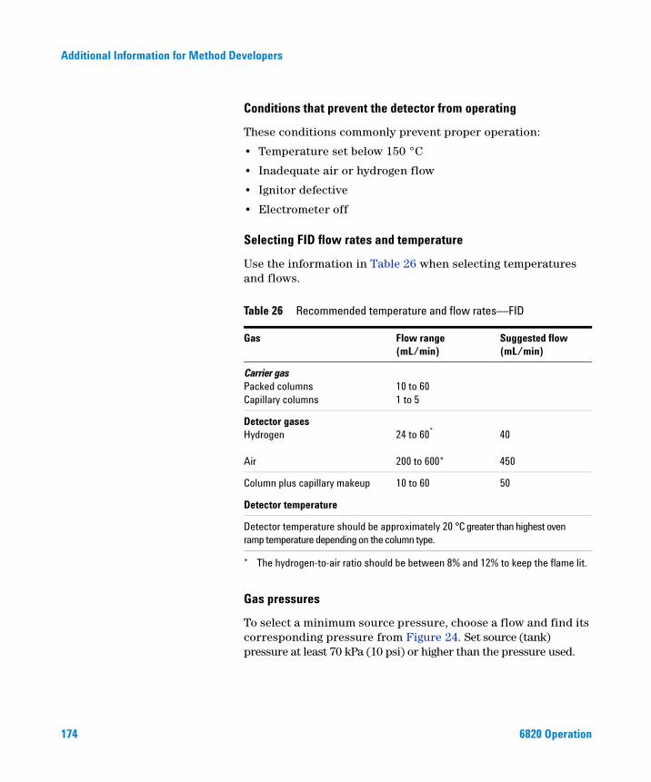
174
Additional Information for Method Developers
Conditions that prevent the detector from operating
These conditions commonly prevent proper operation:
• Temperature set below 150 °C
• Inadequate air or hydrogen flow
• Ignitor defective
• Electrometer off
Selecting FID flow rates and temperature
Use the information in Table 26 when selecting temperatures and flows.
Gas pressures
To select a minimum source pressure, choose a flow and find its corresponding pressure from Figure 24. Set source (tank) pressure at least 70 kPa (10 psi) or higher than the pressure used.
Table 26 Recommended temperature and flow rates—FID
Gas Flow range(mL/min)
Suggested flow(mL/min)
Carrier gasPacked columnsCapillary columns
10 to 601 to 5
Detector gasesHydrogen
Air
24 to 60*
200 to 600*
* The hydrogen-to-air ratio should be between 8% and 12% to keep the flame lit.
40 450
Column plus capillary makeup 10 to 60 50
Detector temperature
Detector temperature should be approximately 20 °C greater than highest oven ramp temperature depending on the column type.
6820 Operation
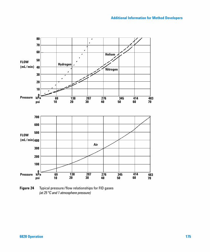
Additional Information for Method Developers
Figure 24 Typical pressure/flow relationships for FID gases(at 25 °C and 1 atmosphere pressure)
69 138 207 276 345 414 4830
10
20
30
40
50
60
70
80
kPapsi
Pressure 10 20 30 40 50 60 70
FLOW(mL/min)
FLOW(mL/min)
69 138 207 276 345 414 483kPapsi
Pressure 10 20 30 40 50 60 70
100
200
300
400
500
600
700
0
Hydrogen
Helium
Nitrogen
Air
6820 Operation 175
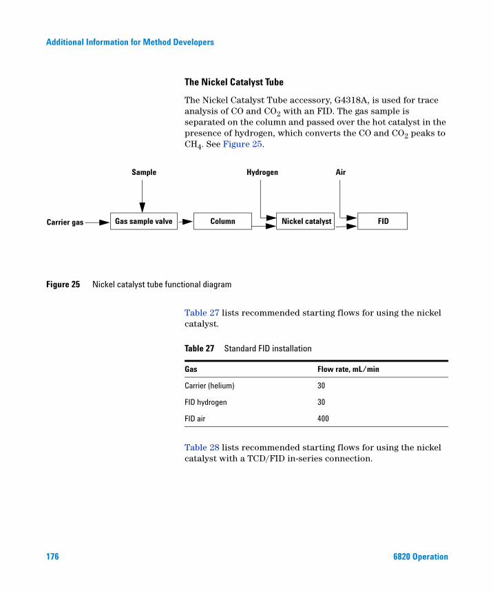
176
Additional Information for Method Developers
The Nickel Catalyst Tube
The Nickel Catalyst Tube accessory, G4318A, is used for trace analysis of CO and CO2 with an FID. The gas sample is separated on the column and passed over the hot catalyst in the presence of hydrogen, which converts the CO and CO2 peaks to CH4. See Figure 25.
Figure 25 Nickel catalyst tube functional diagram
Gas sample valve Column Nickel catalyst FIDCarrier gas
Hydrogen AirSample
Table 27 lists recommended starting flows for using the nickel catalyst.
Table 28 lists recommended starting flows for using the nickel catalyst with a TCD/FID in-series connection.
Table 27 Standard FID installation
Gas Flow rate, mL/min
Carrier (helium) 30
FID hydrogen 30
FID air 400
6820 Operation
Additional Information for Method Developers
6820 Operation
Table 28 TCD/FID in-series installation
Gas Flow rate, mL/min
Carrier (helium) 30
TCD switching flow 25
FID hydrogen 45
FID air 500
The nickel catalyst tube can be damaged by exposure to air.
CAUTIONTemperature The nickel catalyst tube is usually mounted in the back inlet position and controlled by the back inlet temperature setpoint. For most analyses, set these temperatures:
• Nickel catalyst tube 375 °C
• FID 400 °C
Thermal Conductivity Detector
Because the TCD does not destroy the sample during the detection process, this detector can be hooked up in series to a flame ionization detector or electron capture detector.
Conditions that prevent the detector from operating
Three common conditions can prevent proper operation:
• Detector temperature set below 150 °C
• Broken or shorted filament
• Reference gas flow is zero or Off
Filament passivation
The tungsten-rhenium TCD filament has been chemically passivated to protect against oxygen damage. However, chemically active compounds such as acids and halogenated
177
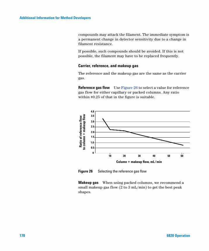
178
Additional Information for Method Developers
compounds may attack the filament. The immediate symptom is a permanent change in detector sensitivity due to a change in filament resistance.
If possible, such compounds should be avoided. If this is not possible, the filament may have to be replaced frequently.
Carrier, reference, and makeup gas
The reference and the makeup gas are the same as the carrier gas.
Reference gas flow Use Figure 26 to select a value for reference gas flow for either capillary or packed columns. Any ratio within ±0.25 of that in the figure is suitable.
Makeup gas When using packed columns, we recommend a small makeup gas flow (2 to 3 mL/min) to get the best peak shapes.
Figure 26 Selecting the reference gas flow
4.0
3.5
3.0
2.5
2.0
1.5
1.0
0.5
010 20 30 40 50 60
Rat
io o
f ref
eren
ce fl
owto
col
umn
+ m
akeu
p flo
w
Column + makeup flow, mL/min
6820 Operation
Additional Information for Method Developers
6820 Operation
Selecting TCD flow rates and temperature
Use the information in Table 29 when selecting temperatures and flows for the TCD.
Gas pressures Use Figure 27 to locate minimum source pressures. Set source (tank) pressure at least 70 kPa (10 psi) or higher than the pressure used.
Table 29 Recommended flow rates and temperatures
Gas type Flow range
Carrier gas(hydrogen, helium, nitrogen)
Packed, 10 to 60 mL/minCapillary, 1 to 5 mL/min
Reference (same gas type as carrier)
15 to 60 mL/min See Figure 27 to select a value.
Capillary makeup (same gas type as carrier)
5 to 15 mL/min—capillary columns2 to 3 mL/min—packed columns
Detector temperature
<150 °C, cannot turn on filamentDetector temperature should be 30°C to 50°C greater than highest oven ramp temperature.
179
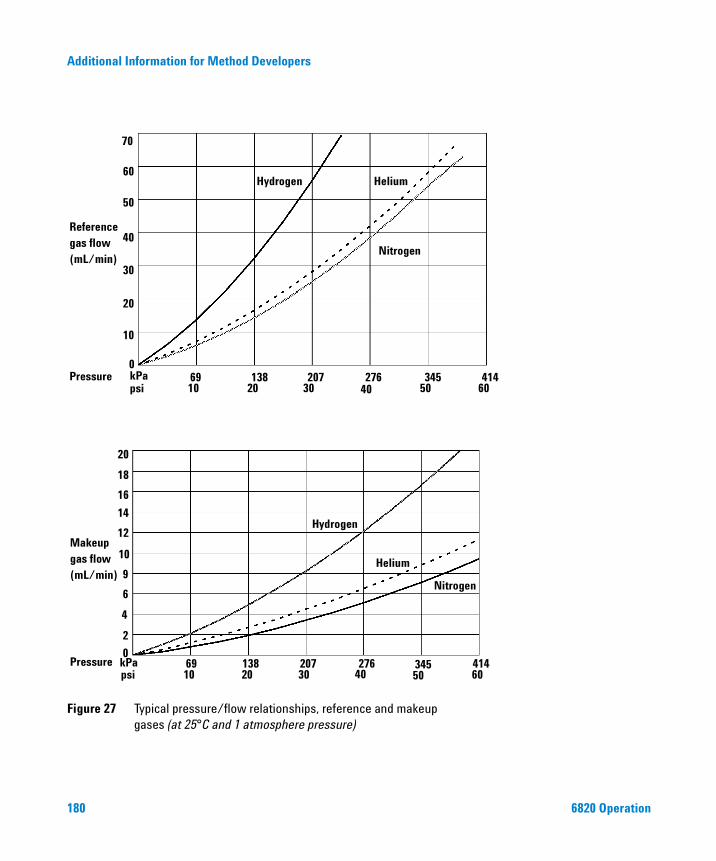
Additional Information for Method Developers
Figure 27 Typical pressure/flow relationships, reference and makeupgases (at 25°C and 1 atmosphere pressure)
69 138 207 276 345 414
10
20
30
40
50
60
70
0
Hydrogen Helium
Nitrogen
10 20 30 50 60Pressure
psi
Referencegas flow(mL/min)
40kPa
1069 138
20207
30 40276 345
50414
60
Nitrogen
Helium
Hydrogen
Makeupgas flow(mL/min)
kPaPressurepsi
20
18
16
14
12
10
9
6
4
2
0
180 6820 Operation
Additional Information for Method Developers
6820 Operation
Negative polarity
Sample components with higher thermal conductivities than the carrier gas produce negative peaks. For example, helium or hydrogen form a negative peak with nitrogen or argon-methane as the carrier gas.
Neg polarity ON inverts the peak so the integrator or Agilent data system (Cerity Chemical) can measure it. You can set Neg polarity as a run time event. See “Run Time Programming: Using Run Time Events” on page 153.
Analyzing for hydrogen
Hydrogen is the only element with thermal conductivity greater than helium, and mixtures of small amounts of hydrogen (<20%) in helium at moderate temperatures exhibit thermal conductivities less than either component alone. If you are analyzing for hydrogen with helium carrier gas, a hydrogen peak may appear as positive, negative, or as a split peak.
There are two solutions to this problem:
• Use nitrogen or argon-methane as carrier gas. This eliminates problems inherent with using helium as carrier, but causes reduced sensitivity to components other than hydrogen.
• Operate the detector at higher temperatures — from 200 °C to 300 °C.
You can find the correct detector operating temperature by analyzing a known range of hydrogen concentrations, increasing the operating temperature until the hydrogen peak exhibits normal shape and is always in the same direction (negative relative to normal response to air or propane) regardless of concentration. This temperature also ensures high sensitivity and linear dynamic range.
See also “Negative polarity” on page 181.
181
Additional Information for Method Developers
Electron Capture Detector
182
Safety precautions when handling ECDs
Always observe the following precautions:
• Never eat, drink, or smoke when handling ECDs.
• Always wear safety glasses when working with or near open ECDs.
• Wear protective clothing such as laboratory jackets, safety glasses, and gloves, and follow good laboratory practices. Wash hands thoroughly with a mild non-abrasive cleaner after handling ECDs.
• Cap the inlet and outlet fittings when the ECD is not in use.
• Connect the ECD exhaust vent to a fume hood or vent it to the outside. In the United States, see the latest revision of Title 10, Code of Federal Regulations, part 20, (including appendix B) or the applicable State regulation. For other countries, consult with the appropriate agency for equivalent requirements.
Agilent Technologies recommends a vent line inside diameter of 6 mm (1/4-inch) or greater. With a line of this diameter, the length is not critical.
Linearity
The ECD response factor versus concentration curve is linear for four orders of magnitude or more (linear dynamic range = 104 or higher) for a broad range of compounds. You should still run a calibration curve on your samples to find the limits of the linear range for your materials.
Detector gas
The ECD operates with either nitrogen or argon/methane as the makeup and anode purge gas.
Because of the high detector sensitivity, carrier and makeup gas must be dry and oxygen-free. Moisture, chemical, and oxygen traps in good condition should be installed in carrier and makeup gas supply lines.
6820 Operation

Additional Information for Method Developers
6820 Operation
Selecting ECD flow rates and temperatures
To prevent peak tailing and to keep the cell clean, the detector temperature should be set higher than the highest oven temperature used — the setpoint should be based on the elution temperature of the last compound. If you operate at excessively high temperatures, your results will not necessarily improve and you may increase sample and column decomposition.
Use the information in Table 30 when selecting temperatures and flows. Maximum source pressure must not exceed 100 psi. Use the maximum source pressure to achieve maximum makeup flow rate.
Table 30 Operating parameters
Gas Recommended flow range
Carrier gas Packed columns (nitrogen or argon-methane)Capillary columns(hydrogen, nitrogen,or argon-methane)
30 to 60 mL/min
0.1 to 20 mL/min,depending on diameter
Capillary makeup(nitrogen or argon-methane)
10 to 150 mL/min(30 to 60 mL/min typical)
Temperature 250 °C to 400 °CDetector temperature is typically set 25 °C greater than the highest oven ramp temperature
• Normally, the carrier gas is the same as the makeup gas. If the GC uses a
NOTE custom configuration and the carrier gas type is different from the makeup gastype, the makeup gas flow rate must be at least three times the carrier gas flow rate.
• ECD sensitivity can be increased by reducing the makeup gas flow rate.• ECD chromatographic speed (for fast peaks) can be increased by increasing the
makeup gas flow rate.
183
184
Additional Information for Method Developers
ECD output
If you intend to use the analog output from the ECD, you must set the output Range to 10. See “Setting signals” on page 95.
Nitrogen Phosphorus Detector
The NPD passes sample and carrier through a hydrogen/air plasma. A heated ceramic source, called the bead, is just above the jet. The low hydrogen/air ratio cannot sustain a flame, minimizing hydrocarbon ionization, while the alkali ions on the bead surface facilitate ionization of nitrogen- or phosphorous-organic compounds. The output current is proportional to the number of ions collected. It is sensed by an electrometer, converted to digital form, and sent to an output device.
Conditions that prevent the NPD from operating
• If the detector temperature is below 150°C or the oven is off, the Adjust offset process will not start.
Gas purity
Because of its high sensitivity, the NPD requires very pure gases. We strongly recommend that moisture and organics traps be used on the carrier gas and all detector gases, including the detector hydrogen, air, and makeup gases.
The bead
There are three setpoints associated with the bead—Adjust offset, Bead voltage, and Equib time.
Adjust offset
When you enter a value here, or press [On] to use the stored value, the bead heats, and the bead voltage adjusts until Output is stable and equal to the entered value. There are five stages of Adjust offset:
1.
Detector off When the detector is off, Adjust offset and Bead voltage are Off and initial Output is displayed. Press [Config] [Front Det] or [Config] [Back Det].6820 Operation
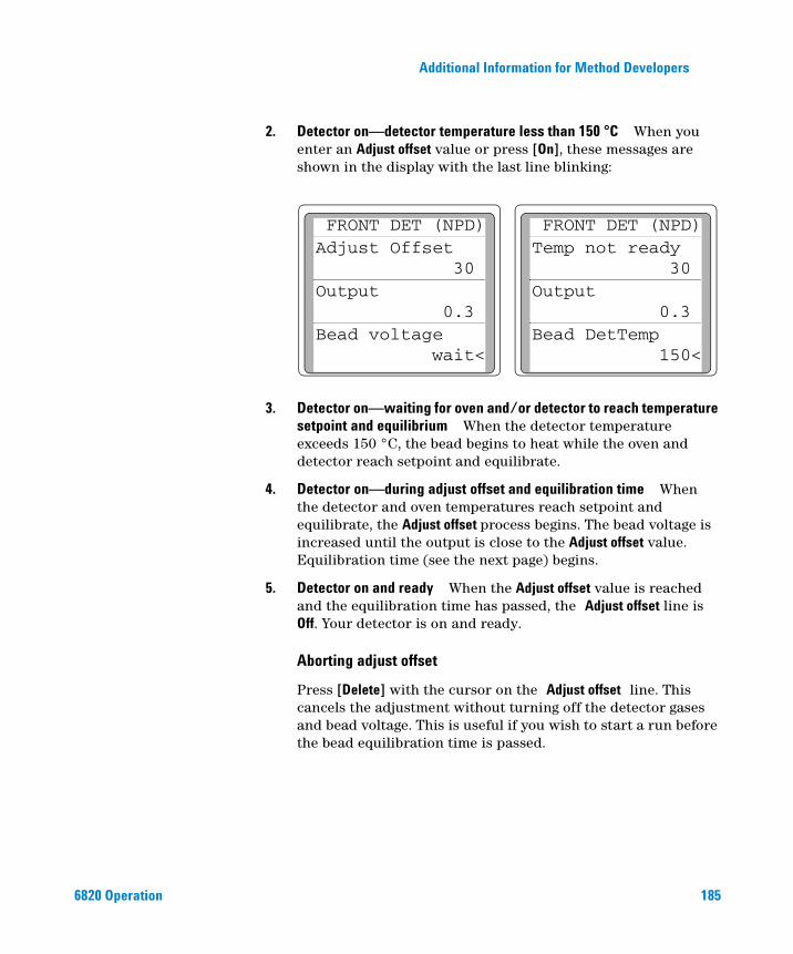
Additional Information for Method Developers
2.
6820 Operation
Detector on—detector temperature less than 150 °C When you enter an Adjust offset value or press [On], these messages are shown in the display with the last line blinking:
FRONT DET (NPD)Adjust Offset
30Output
0.3Bead voltage
wait<
FRONT DET (NPD)Temp not ready
30Output
0.3Bead DetTemp
150<
3.
Detector on—waiting for oven and/or detector to reach temperature setpoint and equilibrium When the detector temperature exceeds 150 °C, the bead begins to heat while the oven and detector reach setpoint and equilibrate.4.
Detector on—during adjust offset and equilibration time When the detector and oven temperatures reach setpoint and equilibrate, the Adjust offset process begins. The bead voltage is increased until the output is close to the Adjust offset value. Equilibration time (see the next page) begins.5.
Detector on and ready When the Adjust offset value is reached and the equilibration time has passed, the Adjust offset line is Off. Your detector is on and ready.Aborting adjust offset
Press [Delete] with the cursor on the Adjust offset line. This cancels the adjustment without turning off the detector gases and bead voltage. This is useful if you wish to start a run before the bead equilibration time is passed.
185
186
Additional Information for Method Developers
Turning off the detector
If you turn Adjust offset [Off] at any time, the bead voltage turns off.
CAUTIONSetting adjust offset on the clock table
You can use the Clock table feature to turn the Adjust offset on at a specified time.
It is not recommended that you Adjust offset between runs. Before the
CAUTIONoven reaches its initial setpoint and the system is thermally stable, column bleed and residual peak tailing can mask an otherwise stable baseline. This can waste time between runs.Turning hydrogen off during a solvent peak
When using the NPD, the baseline shifts after a solvent peak and can take some time to stabilize, especially with chlorinated solvents. To minimize this effect, turn off the hydrogen flow during the solvent peak and turn it back on after the solvent elutes. With this technique, the baseline recovers to its original value in less than 30 seconds. This also extends the life of the bead.
Turning hydrogen off between runs
To extend bead life, turn off the hydrogen flow between runs. Leave all other flows and the detector temperature on. Turn on the hydrogen flow for the next run; the bead will ignite almost immediately.
6820 Operation
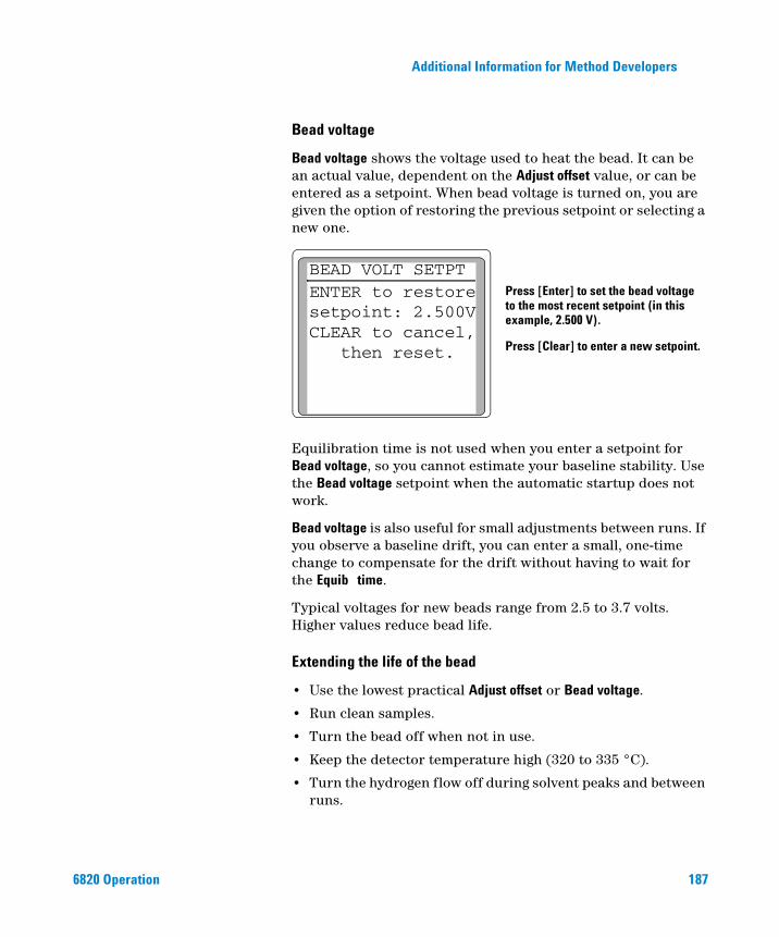
Additional Information for Method Developers
6820 Operation
Bead voltage
Bead voltage shows the voltage used to heat the bead. It can be an actual value, dependent on the Adjust offset value, or can be entered as a setpoint. When bead voltage is turned on, you are given the option of restoring the previous setpoint or selecting a new one.
Equilibration time is not used when you enter a setpoint for Bead voltage, so you cannot estimate your baseline stability. Use the Bead voltage setpoint when the automatic startup does not work.
Bead voltage is also useful for small adjustments between runs. If you observe a baseline drift, you can enter a small, one-time change to compensate for the drift without having to wait for the Equib time.
Typical voltages for new beads range from 2.5 to 3.7 volts. Higher values reduce bead life.
Extending the life of the bead
• Use the lowest practical Adjust offset or Bead voltage.
• Run clean samples.
• Turn the bead off when not in use.
• Keep the detector temperature high (320 to 335 °C).
• Turn the hydrogen flow off during solvent peaks and between runs.
BEAD VOLT SETPTENTER to restoresetpoint: 2.500VCLEAR to cancel,
then reset.
Press [Enter] to set the bead voltageto the most recent setpoint (in thisexample, 2.500 V).
Press [Clear] to enter a new setpoint.
187
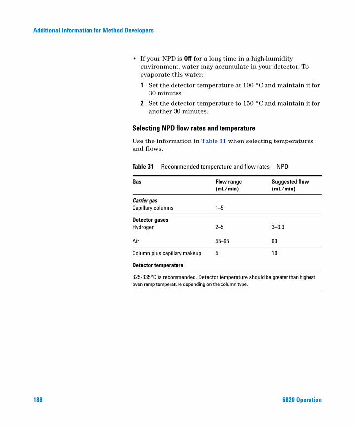
188
Additional Information for Method Developers
• If your NPD is Off for a long time in a high-humidity environment, water may accumulate in your detector. To evaporate this water:
1 Set the detector temperature at 100 °C and maintain it for 30 minutes.
2 Set the detector temperature to 150 °C and maintain it for another 30 minutes.
Selecting NPD flow rates and temperature
Use the information in Table 31 when selecting temperatures and flows.
Table 31 Recommended temperature and flow rates—NPD
Gas Flow range(mL/min)
Suggested flow(mL/min)
Carrier gasCapillary columns 1–5
Detector gasesHydrogen
Air
2–5
55–65
3–3.3 60
Column plus capillary makeup 5 10
Detector temperature
325-335°C is recommended. Detector temperature should be greater than highest oven ramp temperature depending on the column type.
6820 Operation
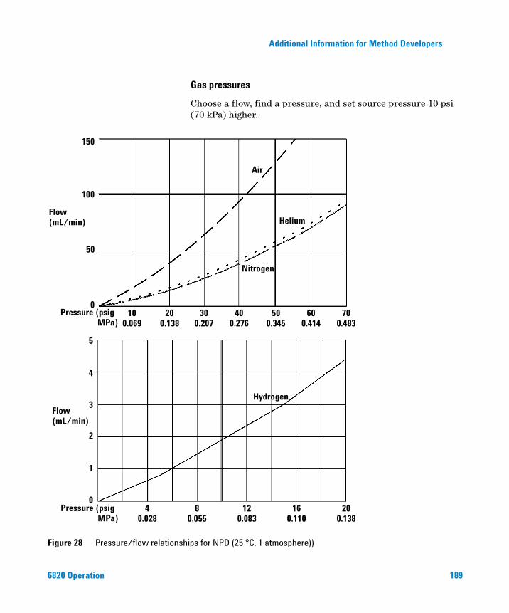
Additional Information for Method Developers
6820 Operation
Gas pressures
Choose a flow, find a pressure, and set source pressure 10 psi (70 kPa) higher..
Figure 28 Pressure/flow relationships for NPD (25 °C, 1 atmosphere))
Flow(mL/min)
Flow(mL/min)
Pressure (psigMPa)
Pressure (psigMPa)
150
100
50
0
5
4
3
2
1
0
Air
Helium
Nitrogen
Hydrogen
100.069
200.138
300.207
400.276
500.345
600.414
700.483
40.028
80.055
120.083
160.110
200.138
189
Additional Information for Method Developers
Valves
190
The GC Fundamentals manual included on the 6820 GC User Information
NOTECD-ROM contains details about how valves work.The 6820 GC holds up to four valves in a heated valve box on top of the oven. When installing valves, using the Agilent valve box is preferred because it provides a stable temperature zone, isolated from the column oven.
Types of valves
The 6820 supports two types of valves: sampling and switching. Of the four valves you can control, only two can be configured as sampling valves (gas or liquid). If desired, all valves can be configured as switching.
The main differences between sampling and switching valves are:
• The plumbing connections
• How the valve interacts with the run
The GC incorporates the sampling valve more directly into the run process: valve actuation corresponds with the start of data collection. On the other hand, a switching valve can be activated at any time during the run, and does not correspond to a “start” command.
For more information on the capabilities of valves and a full listing of typical valve applications available on the 6820, contact your local Agilent sales office.
The valve box
Figure 29 shows a top-down view of the 6820. The valve box is located on the top of the oven, between the inlets and detectors. Open the detector cover to access it.
6820 Operation
Additional Information for Method Developers
Figure 29 The valve box
DetectorsInlets
Top view of 6820, with detector cover up
Valve box
Heated zone 1 Heated zone 2
Valve
Back of GC
6820 Operation
Heating the valves
The valve box can contain up to two heated blocks (the shaded areas in Figure 29), each with two valve mounting locations. The middle hole on each block is used to pass tubing into the column oven.
If using one or two valves, mount them on the same block. This allows them to be heated using only one control channel (Aux 1 or Aux 2, depending on how the heaters are wired).
If using more than two valves, both Aux 1 and Aux 2 must be used for heating them. Set them at the same temperature.
For configuration information, see “Configure the Aux thermal zones” on page 74. Agilent recommends configuring the Aux zones for valves as shown in Figure 29.
191
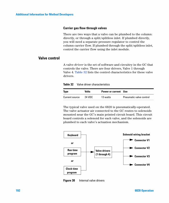
192
Additional Information for Method Developers
Carrier gas flow through valves
There are two ways that a valve can be plumbed to the column: directly, or through a split/splitless inlet. If plumbed directly, you will need a separate pressure regulator to control the column carrier flow. If plumbed through the split/splitless inlet, control the carrier flow using the inlet module.
Valve control
A valve driver is the set of software and circuitry in the GC that controls the valve. There are four drivers, Valve 1 through Valve 4. Table 32 lists the control characteristics for these valve drivers.
The typical valve used on the 6820 is pneumatically-operated. The valve actuator air connected to the GC routes to solenoids mounted near the GC’s main printed circuit board. This circuit board controls a solenoid for each valve, and the solenoids are plumbed to each valve’s actuation mechanism.
Table 32 Valve driver characteristics
Type Volts Power or current Use
Current source 24 VDC 13 watts Pneumatic valve control
Figure 30 Internal valve drivers
Keyboard
or
Run time program
or
Clock timeprogram
Connector V1
Solenoid wiring bracket
Connector V2
Connector V3
Connector V4
Valve drivers (1 through 4)
6820 Operation
Additional Information for Method Developers
6820 Operation
There is no direct relationship between the location of a valve in the valve box and the driver that controls it. This depends on how the solenoids are wired and the actuators are plumbed.
193
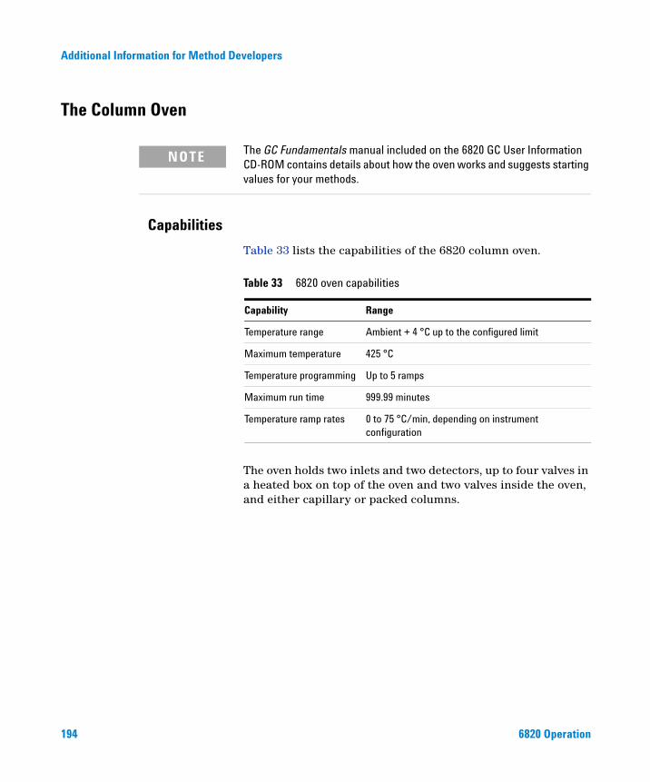
Additional Information for Method Developers
The Column Oven
194
The GC Fundamentals manual included on the 6820 GC User Information
Capabilities
NOTECD-ROM contains details about how the oven works and suggests starting values for your methods.
Table 33 lists the capabilities of the 6820 column oven.
The oven holds two inlets and two detectors, up to four valves in a heated box on top of the oven and two valves inside the oven, and either capillary or packed columns.
Table 33 6820 oven capabilities
Capability Range
Temperature range Ambient + 4 °C up to the configured limit
Maximum temperature 425 °C
Temperature programming Up to 5 ramps
Maximum run time 999.99 minutes
Temperature ramp rates 0 to 75 °C/min, depending on instrument configuration
6820 Operation
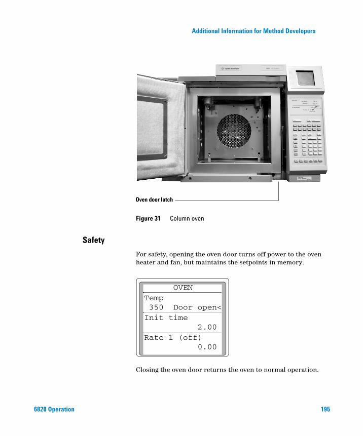
Additional Information for Method Developers
6820 Operation
Figure 31 Column oven
Oven door latch
Safety
For safety, opening the oven door turns off power to the oven heater and fan, but maintains the setpoints in memory.
Closing the oven door returns the oven to normal operation.
OVEN Temp350 Door open<Init time
2.00Rate 1 (off)
0.00
195
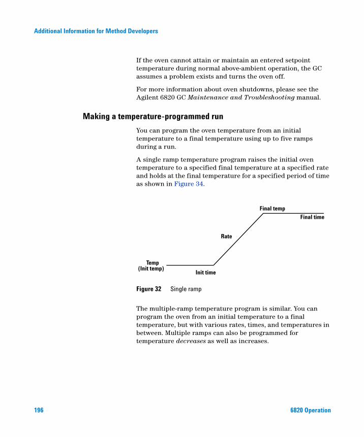
196
Additional Information for Method Developers
If the oven cannot attain or maintain an entered setpoint temperature during normal above-ambient operation, the GC assumes a problem exists and turns the oven off.
For more information about oven shutdowns, please see the Agilent 6820 GC Maintenance and Troubleshooting manual.
Making a temperature-programmed run
You can program the oven temperature from an initial temperature to a final temperature using up to five ramps during a run.
A single ramp temperature program raises the initial oven temperature to a specified final temperature at a specified rate and holds at the final temperature for a specified period of time as shown in Figure 34.
The multiple-ramp temperature program is similar. You can program the oven from an initial temperature to a final temperature, but with various rates, times, and temperatures in between. Multiple ramps can also be programmed for temperature decreases as well as increases.
Figure 32 Single ramp
Temp(Init temp)
Init time
Rate
Final time
Final temp
6820 Operation
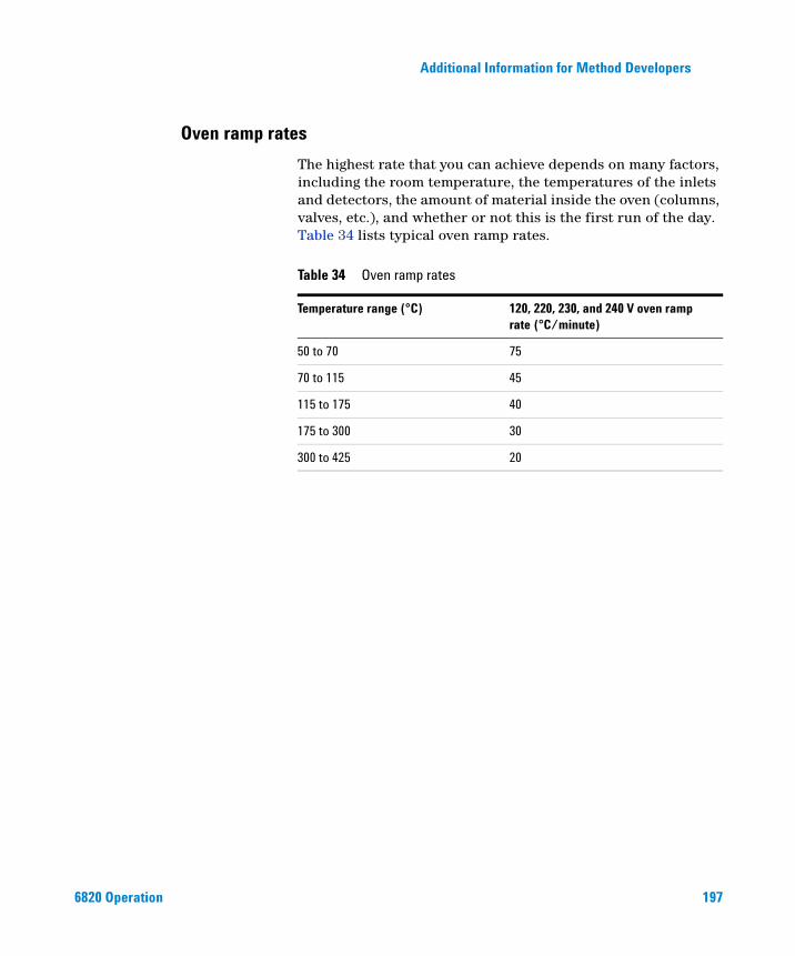
Additional Information for Method Developers
Oven ramp rates
6820 Operation
The highest rate that you can achieve depends on many factors, including the room temperature, the temperatures of the inlets and detectors, the amount of material inside the oven (columns, valves, etc.), and whether or not this is the first run of the day. Table 34 lists typical oven ramp rates.
Table 34 Oven ramp rates
Temperature range (°C) 120, 220, 230, and 240 V oven ramp rate (°C/minute)
50 to 70 75
70 to 115 45
115 to 175 40
175 to 300 30
300 to 425 20
197
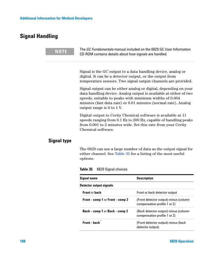
Additional Information for Method Developers
Signal Handling
198
The GC Fundamentals manual included on the 6820 GC User Information
NOTECD-ROM contains details about how signals are handled.Signal is the GC output to a data handling device, analog or digital. It can be a detector output, or the output from temperature sensors. Two signal output channels are provided.
Signal output can be either analog or digital, depending on your data handling device. Analog output is available at either of two speeds, suitable to peaks with minimum widths of 0.004 minutes (fast data rate) or 0.01 minutes (normal rate). Analog output range is 0 to 1 V.
Digital output to Cerity Chemical software is available at 11 speeds ranging from 0.1 Hz to 200 Hz, capable of handling peaks from 0.001 to 2 minutes wide. Set this rate from your Cerity Chemical software.
Signal type
The 6820 can use a large number of data as the output signal for either channel. See Table 35 for a listing of the most useful options.
Table 35 6820 Signal choices
Signal name Description
Detector output signals
Front or back Front or back detector output
Front - comp 1 or Front - comp 2 (Front detector output) minus (column compensation profile 1 or 2)
Back - comp 1 or Back - comp 2 (Back detector output) minus (column compensation profile 1 or 2)
Front - back* (Front detector output) minus (back detector output)
6820 Operation
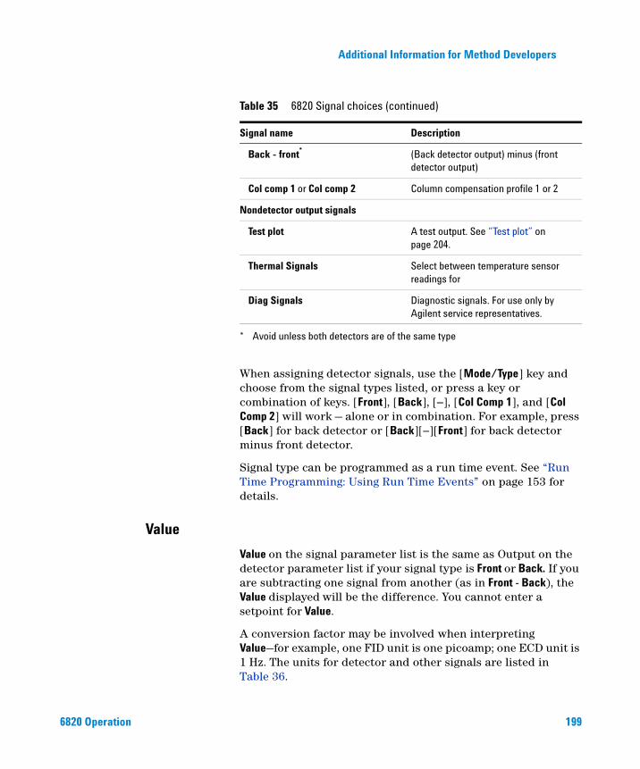
Additional Information for Method Developers
6820 Operation
When assigning detector signals, use the [Mode/Type] key and choose from the signal types listed, or press a key or combination of keys. [Front], [Back], [–], [Col Comp 1], and [Col Comp 2] will work — alone or in combination. For example, press [Back] for back detector or [Back][–][Front] for back detector minus front detector.
Signal type can be programmed as a run time event. See “Run Time Programming: Using Run Time Events” on page 153 for details.
Back - front* (Back detector output) minus (front detector output)
Col comp 1 or Col comp 2 Column compensation profile 1 or 2
Nondetector output signals
Test plot A test output. See “Test plot” on page 204.
Thermal Signals Select between temperature sensor readings for
Diag Signals Diagnostic signals. For use only by Agilent service representatives.
* Avoid unless both detectors are of the same type
Table 35 6820 Signal choices (continued)
Signal name Description
Value
Value on the signal parameter list is the same as Output on the detector parameter list if your signal type is Front or Back. If you are subtracting one signal from another (as in Front - Back), the Value displayed will be the difference. You cannot enter a setpoint for Value.
A conversion factor may be involved when interpreting Value—for example, one FID unit is one picoamp; one ECD unit is 1 Hz. The units for detector and other signals are listed in Table 36.
199
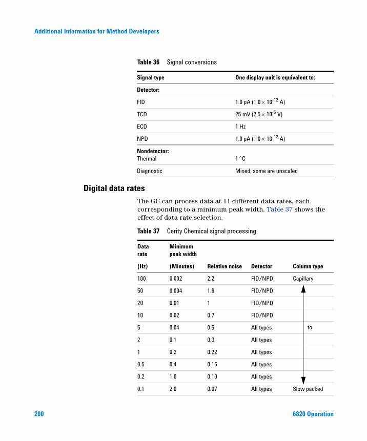
200
Additional Information for Method Developers
Table 36 Signal conversions
Signal type One display unit is equivalent to:
Detector:
FID 1.0 pA (1.0 × 10⁻¹² A)
TCD 25 mV (2.5 × 10⁻⁵ V)
ECD 1 Hz
NPD 1.0 pA (1.0 × 10⁻¹² A)
Nondetector:Thermal 1 °C
Diagnostic Mixed; some are unscaled
Digital data rates
The GC can process data at 11 different data rates, each corresponding to a minimum peak width. Table 37 shows the effect of data rate selection.Table 37 Cerity Chemical signal processing
Datarate
Minimum peak width
(Hz) (Minutes) Relative noise Detector Column type
100 0.002 2.2 FID/NPD Capillary
50 0.004 1.6 FID/NPD
20 0.01 1 FID/NPD
10 0.02 0.7 FID/NPD
5 0.04 0.5 All types
2 0.1 0.3 All types
1 0.2 0.22 All types
0.5 0.4 0.16 All types
0.2 1.0 0.10 All types
0.1 2.0 0.07 All types Slow packed
to
6820 Operation
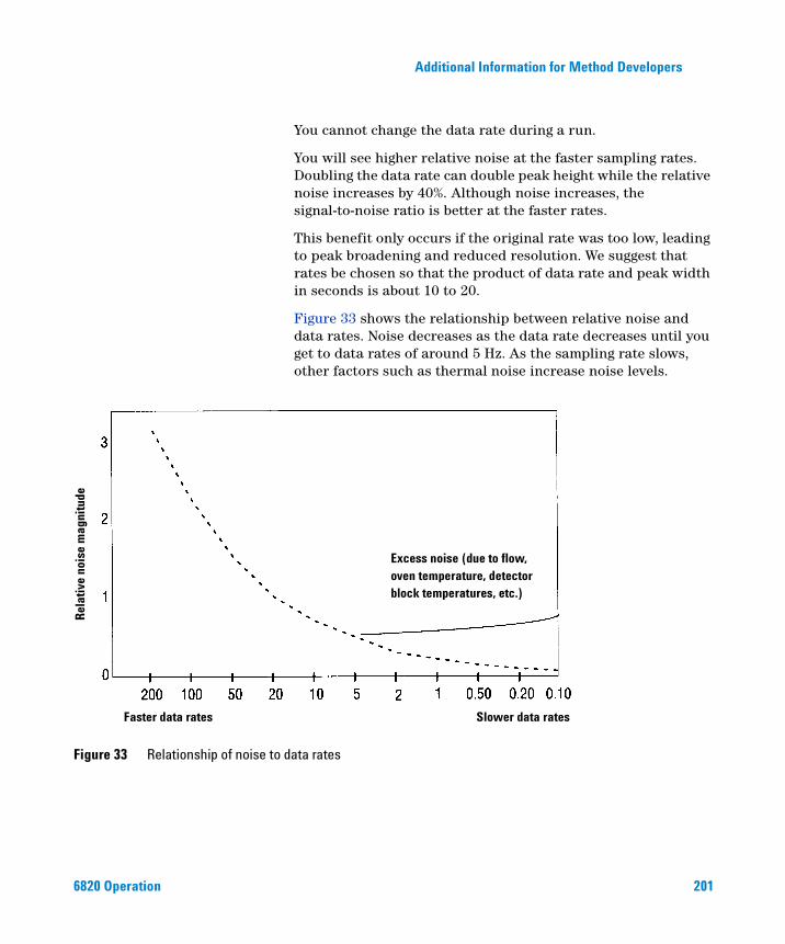
Additional Information for Method Developers
6820 Operation
You cannot change the data rate during a run.
You will see higher relative noise at the faster sampling rates. Doubling the data rate can double peak height while the relative noise increases by 40%. Although noise increases, the signal-to-noise ratio is better at the faster rates.
This benefit only occurs if the original rate was too low, leading to peak broadening and reduced resolution. We suggest that rates be chosen so that the product of data rate and peak width in seconds is about 10 to 20.
Figure 33 shows the relationship between relative noise and data rates. Noise decreases as the data rate decreases until you get to data rates of around 5 Hz. As the sampling rate slows, other factors such as thermal noise increase noise levels.
Figure 33 Relationship of noise to data rates
Excess noise (due to flow,oven temperature, detectorblock temperatures, etc.)
Slower data ratesFaster data rates
Rel
ativ
e no
ise
mag
nitu
de
201
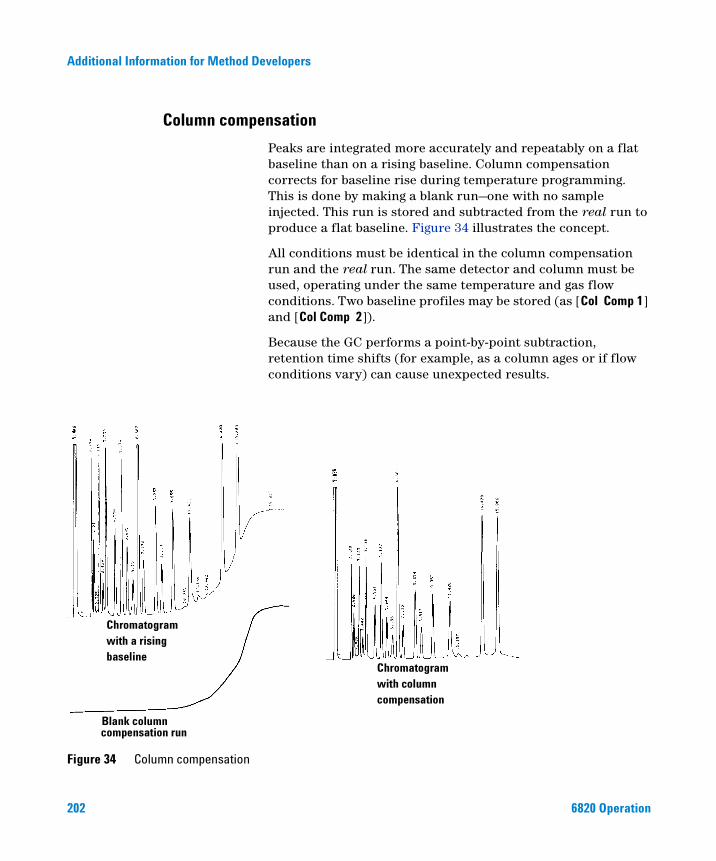
Additional Information for Method Developers
Column compensation
202
Peaks are integrated more accurately and repeatably on a flat baseline than on a rising baseline. Column compensation corrects for baseline rise during temperature programming. This is done by making a blank run—one with no sample injected. This run is stored and subtracted from the real run to produce a flat baseline. Figure 34 illustrates the concept.
All conditions must be identical in the column compensation run and the real run. The same detector and column must be used, operating under the same temperature and gas flow conditions. Two baseline profiles may be stored (as [Col Comp 1] and [Col Comp 2]).
Because the GC performs a point-by-point subtraction, retention time shifts (for example, as a column ages or if flow conditions vary) can cause unexpected results.
Figure 34 Column compensation
Chromatogramwith a risingbaseline
compensation runBlank column
Chromatogramwith columncompensation
6820 Operation
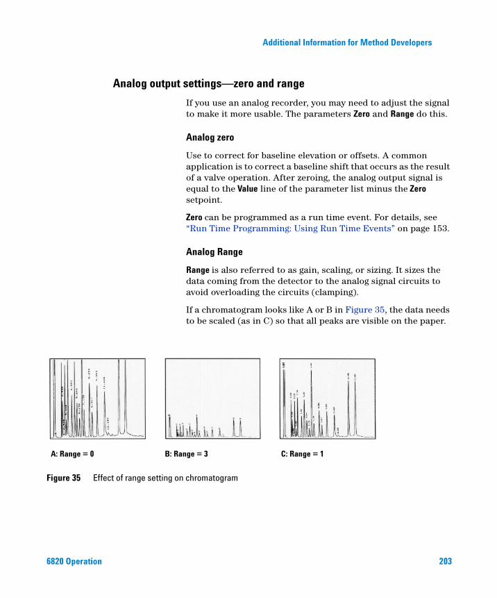
Additional Information for Method Developers
Analog output settings—zero and range
6820 Operation
If you use an analog recorder, you may need to adjust the signal to make it more usable. The parameters Zero and Range do this.
Analog zero
Use to correct for baseline elevation or offsets. A common application is to correct a baseline shift that occurs as the result of a valve operation. After zeroing, the analog output signal is equal to the Value line of the parameter list minus the Zero setpoint.
Zero can be programmed as a run time event. For details, see “Run Time Programming: Using Run Time Events” on page 153.
Analog Range
Range is also referred to as gain, scaling, or sizing. It sizes the data coming from the detector to the analog signal circuits to avoid overloading the circuits (clamping).
If a chromatogram looks like A or B in Figure 35, the data needs to be scaled (as in C) so that all peaks are visible on the paper.
Figure 35 Effect of range setting on chromatogram
A: Range = 0 B: Range = 3 C: Range = 1
203
204
Additional Information for Method Developers
Valid setpoints are from 0 to 13 and represent 20 (1) to 213 (8192). Changing a setpoint by 1 changes the width of the chromatogram by a factor of 2. The chromatograms in Figure 35 illustrate this. Use the smallest possible value to minimize integration error.
For analog output of 0 to 1 mV:
There are limits to usable range settings for some detectors. Table 38 lists the valid range setpoints by detector.
Range may be run time programmed. See “Run Time Programming: Using Run Time Events” on page 153 for details.
Table 38 Valid range settings per detector
Detector Usable range settings (2x)
FID 0 to 13
TCD 0 to 6
ECD 0 to 6
NPD 0 to 13
One display unit 1 mV
2Range
2Attn×
-------------------------------------------=
Test plot
The test plot (shown in Figure 36) is an internally generated “chromatogram” that can be assigned to a signal output channel. It consists of three baseline-resolved, repeating peaks. The area of the largest is approximately 1 Volt-s, the middle one is 0.1 times the largest, and the smallest is 0.01 times the largest.
6820 Operation
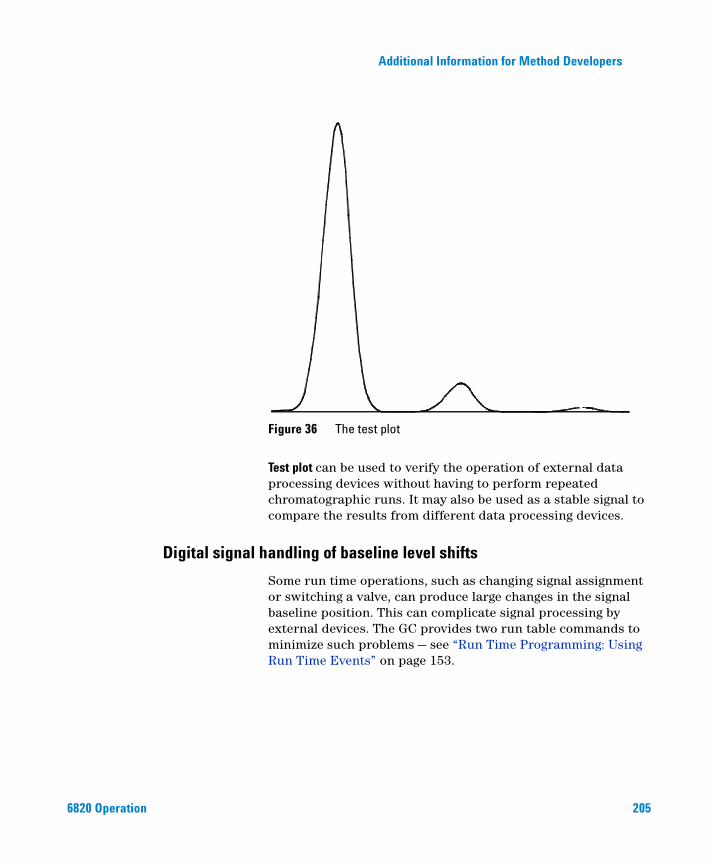
Additional Information for Method Developers
6820 Operation
Test plot can be used to verify the operation of external data processing devices without having to perform repeated chromatographic runs. It may also be used as a stable signal to compare the results from different data processing devices.
Figure 36 The test plot
Digital signal handling of baseline level shifts
Some run time operations, such as changing signal assignment or switching a valve, can produce large changes in the signal baseline position. This can complicate signal processing by external devices. The GC provides two run table commands to minimize such problems — see “Run Time Programming: Using Run Time Events” on page 153.
205

206
Additional Information for Method Developers
Use these commands to surround a baseline-shifting event and bring the new baseline to the previous level, as shown in Figure 37. The Store sig val event must occur before the event that shifts the baseline, and the Sig zero - value event must occur after the baseline has stabilized at the shifted level.
Store sig val Saves the value of the signal at the time of the command.
Sig zero - value Creates a new zero by subtracting the stored value from the current value of the signal and applies this zero to all future values.
Figure 37 Correcting baseline level shifts in digital signals
Baseline level change
Baseline-shifting event occurs
No correctionSignal
Signal
Run time correction3. Sig zero – val event occurs
Time
2. Baseline-shifting event occurs1. Store sig val event occurs
Time
6820 Operation
Additional Information for Method Developers
Instrument Supplies
6820 Operation
The Maintenance and Troubleshooting and Service manuals included on
NOTEthe 6820 GC User Information CD-ROM provide more information instrument supplies.One simple way to help ensure good performance is to use high quality supplies for the instrument gases and chemical traps.
Gases
Always use chromatographic grade carrier gas (99.9995% pure). See Table 39. Dirty input gases are one of the most common causes of contamination.
Table 39 Gas purity recommendations
Carrier gases and capillary makeup gases
Helium 99.9995%
Nitrogen 99.9995%
Hydrogen 99.9995%
Argon/Methane 99.9995%
Detector support gases
Hydrogen 99.9995%
Air (dry) Zero-grade or better
Traps
Use traps to remove residual impurities from your source gases. Table 40 lists some common Agilent traps.
207
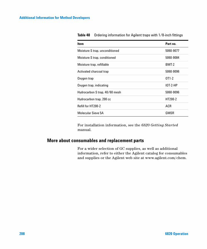
208
Additional Information for Method Developers
For installation information, see the 6820 Getting Started manual.
Table 40 Ordering information for Agilent traps with 1/8-inch fittings
Item Part no.
Moisture S trap, unconditioned 5060-9077
Moisture S trap, conditioned 5060-9084
Moisture trap, refillable BMT-2
Activated charcoal trap 5060-9096
Oxygen trap OT1-2
Oxygen trap, indicating IOT-2-HP
Hydrocarbon S trap, 40/60 mesh 5060-9096
Hydrocarbon trap, 200 cc HT200-2
Refill for HT200-2 ACR
Molecular Sieve 5A GMSR
More about consumables and replacement parts
For a wider selection of GC supplies, as well as additional information, refer to either the Agilent catalog for consumables and supplies or the Agilent web site at www.agilent.com/chem.
6820 Operation
Index
Aactual value, 43adapters, for measuring flows, 130AIR, FID, 124, 129analog output range, 203analog zero, 203ANODE PURGE gas, ECD, 127asterisk, in GC display, 41Aux # keys, 49AUX GAS, ECD, 127AUX GAS, FID, 124, 129AUX GAS, TCD, 125
BBack Det key, 49Back Inlet key, 49Bead
NPD, 184voltage, 187
beep, 43, 59bubble flow meter, 131
Ccalibration option, 59caution message, 44Cerity Chemical
methods, conservation, 162methods, shutdown, 162
Clear key, 62click, key, 59Clock Table
key, 63LED, 46
clock timeadding events, 145deleting events, 146editing events, 145programming, 144, 145
Col Comp n keys, 49
6820 Operation
columncompensation, 202compensation profile, 96compensation, making a run, 98
command, start, 21communications, option, 59compensation
column, 202creating a profile, 96plotting a profile, 98
Config key, 59configuration
instrument, 59oven, 72setpoint status table, 75
cursor, 41
Ddata rate, fast peaks, 95data system, definition, 18default method, 66default parameters, 158Delete key, 62deleting a method, 67detector overview, 170detectors, setting parameters, 84DHCP, for IP addressing, 78diagnostics, option, 59display, 41
blinking, 42LED, 46
EECD, See electron capture detectorediting a method, 67Electrometer
NPD, 88electrometer
ECD, 84FID, 85
electron capture detectorANODE PURGE gas, 127AUX GAS, 127gases, 182linearity, 182safety, 28, 182setting flows, 127
Equilibration timeNPD, 88
equilibration time, oven, 73errors, 44
Ffast peaks, 96FID, See flame ionization detectorfinal temp
LED, 46oven, 79
final time, oven, 79flame ionization detector, 172
AIR flow, 124, 129AUX GAS, 124, 129data rates, 95electrometer, 84, 85fast peaks, 96HYDROGEN gas, 123, 128pressure and flow, 175setting flows, 123, 128
Flow key, 49flow rates, adapters for, 130flow, measuring meter, 131flows, setting, 116
ECD, 127FID, 123purged packed inlet, 121split/splitless inlet, 117TCD, 125
Front Det key, 49Front Inlet key, 49
209

Index
Ggas purity, and ECD performance, 182gas sampling valve, 92gas, hydrogen, safety, 162gas, makeup, definition, 172
HHydrogen
NPD, turning off during solvent peak, 186
hydrogenanalysis for, 181flow (FID), 123, 128
IInfo key, 51Init Temp, oven, 79Initial Temp LED, 46inlet, purged packed
flow ranges, 168setting flows, 121source pressures, 168
inlet, split/splitlessliner selection, 167modes, 167setting flows, 117
inlets, overview, 166IP address, 77isothermal oven, 80
Kkey click, 59keyboard, 47
lock, 59
LLAN communications, 77linearity, ECD, 182liners, split/splitless inlet, choosing, 167Load key, 63loading
default method, 66default parameters, 158
lock, keyboard, 59
Mmakeup gas, definition, 172messages, 44meter, flow measuring, 131method
definition, 148deleting, 67editing, 67loading default, 66mismatch, 159storing, 64
Method key, 63method, definition, 18methods, Cerity Chemical
conservation, 162shutdown, 162
Mode/Type key, 61
NNitrogen-phosphorus detector
adjust offset, 184aborting, 185
bead, 184voltage, 187
electrometer, 88equilibration time, 88hydrogen off, 186solvent peak
turning hydrogen off, 186turning off, 186
Not Ready LED, 46
OOptions key, 58output
analog, 203definition, 198digital rates available, 200signal type, 198
ovenconfiguration, 72equilibration time, 73fast rates, 197isothermal, 80maximum temperature, 73safety, 195specifications, 194temperatures. setting, 79
Oven key, 49
Pparameters
default, 158inlet, 167
polarity, TCD, 181Pre Run LED, 46Prep Run, key, 48procedure
adding eventsclock table, 145run table, 156
auto prep run, 78configuring
setpoint status table, 75valves, 74
controlling valves from the keyboard, 90
creating a column compensation profile, 96
deletingclock table events, 146run table events, 157stored method, 67
editingclock table events, 145run table events, 156stored method, 67
loadingdefault method, 66default parameters, 158
plotting a column compensation profile, 98
210
6820 Operation
Index
programmingclock table events, 144isothermal oven, 80multiple-ramp oven temperature, 81run table events, 155single-ramp oven temperature, 80
storing a method, 64using
column compensation, 98stopwatch, 56
programmingclock table events, 145clock time, 144, 145oven temperature, 196run time, 153, 155
purged packed inletflow ranges, 168flows, setting, 121parameters, 82source pressure, 168
RRamp # key, 50ramp, multiple, oven, 81ramp, single, oven, 80range, analog output, 203Rate LED, 46rate, oven ramp, 197REF gas, TCD, 125reference gas, TCD flow, 178Remote LED, 46RS-232 communications, 76Run LED, 46Run Log key, 56Run Table key, 63run time
adding events, 156deleting events, 157editing events, 156maximum, 81programming, 155total, 81
run, definition, 18
Ssafety, ECD, 28, 182scrolling, 41setpoint
auxiliary heated zone, 94detector, 84inlet, 82oven, 79status table, 54
setpoint value, 43setpoints
provided by Cerity Chemical, 21setting flows
ECD, 127FID, 123purged packed inlet, 121split/splitless inlet, 117TCD, 125
signalanalog, 203fast peaks, 96selecting output, 95store digital, 206type, 198value, 199
Signal n keys, 49single column compensation, 202Solvent peak
NPD, turning hydrogen off, 186split/splitless inlet, 167
flows, setting, 117liners, 167parameters, 82
start command, 21Status key, 52status table, 52Stop key, 48stopwatch, 56Store key, 63storing a method, 64
TTCD, See thermal conductivity detectorTemp key, 49temperature
auxiliary heated zone setpoint, 94ECD setpoint, 84FID setpoint, 86, 89inlet setpoint, 82isothermal, 80oven maximum, 73programmed, 196TCD setpoint, 87
temperature, oven setpoint, 79test plot, 204thermal conductivity detector
AUX GAS, 125carrier gas, 178flow and pressure, 180hydrogen analysis, 181makeup gas, 178negative polarity, 181REF gas flow rates, 178REF gas, setting, 125setting flows, 125
Time key, 54
Vvalue
actual, 43setpoint, 43
valvebox, 190column selection, 91controlling, 90gas sampling, parameters, 92heating configuration, 191
Valve # key, 63
Zzero, analog, 203
6820 Operation
211
Index
212
6820 Operation
Agilent Technologies
© Agilent Technologies, Inc.
Printed in China, April 2005
G1176-90014