agilent 33500 series waveform generatormathys/ecen1400/pdf/references/agilent... ·...
TRANSCRIPT

Agilent 33500 Series Waveform Generator
Operating and Service Guide

Agilent 33500 Series Waveform GeneratorOperating and Service Guide
This document includes user, service, and programming information for the Agilent 33500 Series waveform gen-erators. You can download the latest version of this document from www.agilent.com/find/33500help. The latest ver-sion is also available for mobile devices at www.agilent.com/find/33500mobile.
Agilent welcomes your comments and suggestions to improve our documentation. You can give feedback on this doc-ument at www.agilent.com/find/33500docfeedback.
Operating Information
Safety and Regulatory Information
Models and Options
Introduction to Instrument
Quick Start
Front-Panel Menu Operation
Features and Functions
Waveform Generation Tutorial
SCPI Programming Reference
Introduction to SCPI Language
Alphabetical List of SCPI Commands andQueries
Programming Examples
CommandQuick Reference
Factory Reset State
SCPI Error Messages
Service and Repair Information
Service and Repair Introduction
Calibration and Adjustment

Block Diagram
Power Supplies
Troubleshooting
Self-Test Procedures
Replaceable Parts
Disassembly
IO Libraries and Instrument Drivers
The Agilent IO Libraries Suite software, including installation instructions, is on the Agilent Automation Ready CD-ROM providedwith your instrument.
For information about connecting and configuring USB, LAN, and GPIB interfaces, refer to the Agilent USB/LAN/GPIBInterfaces Connectivity Guide on the Agilent Automation Ready CD-ROM, and at www.agilent.com/find/connectivity.
Web Interface
The instrument includes a built-in Web Interface. You can use this interface over LAN for remote instrument accessand control via a Java™-enabledWeb browser, such as Microsoft® Internet Explorer.
To use the Web Interface:
1. Establish a LAN connection from your PC to the instrument.
2. Open your PC's Web browser.
3. Launch the instrument's Web Interface by entering the instrument's IP address or fully-qualified hostname in thebrowser address field.
4. Follow the instructions in the Web Interface's on-line help.
Example Programs
There are several example programs on the product page Web site (www.agilent.com/find/33500). These are appli-cation-focused programs that demonstrate different programming environments. This document also includes pro-gramming examples to help get you started.
2 Agilent 33500 Series Operating and Service Guide

Contacting Agilent Technologies
You can contact Agilent Technologies for warranty, service, or technical support.
In the United States: (800) 829-4444
In Europe: 31 20 547 2111
In Japan: 0120-421-345
Use www.agilent.com/find/assist for information on contacting Agilent worldwide, or contact your Agilent Technologiesrepresentative.
Trademarks
Microsoft is a trademark or registered trademark of Microsoft Corporation in the United States and/or other countries.Windows,Windows NT, MSWindows, andWindows Vista are trademarks or registered trademarks of Microsoft Cor-poration in the United States and/or other countries.
© Agilent Technologies, Inc. 2012
Revised August, 2012
Agilent 33500 Series Operating and Service Guide 3

Safety and Regulatory Information
Safety and Regulatory Information
Notices
©Agilent Technologies, Inc. 2012
No part of this manual may be reproduced in any form or by any means (including electronic storage and retrieval ortranslation into a foreign language) without prior agreement andwritten consent from Agilent Technologies, Inc. asgoverned by United States and international copyright laws.
Manual Information
33500-90901
First Edition, May 2012Second Edition, August 2012
Agilent Technologies, Inc.900 S. Taft Ave.Loveland, CO 80537 USA
Trademark Acknowledgments
Microsoft is a trademark or registered trademark of Microsoft Corporation in the United States and/or other countries.Windows,Windows NT, MSWindows, andWindows Vista are trademarks or registered trademarks of Microsoft Cor-poration in the United States and/or other countries.
Software and Documentation Updates and Licenses
Agilent releases software updates to fix defects and incorporate product enhancements. For the latest software and doc-umentation, see www.agilent.com/find/33500help. The latest version is also available for mobile devices at www.ag-ilent.com/find/33500mobile.
A portion of the software in this product is licensed under terms of the General Public License Version 2 ("GPLv2"). Thetext of the license and source code can be found at www.agilent.com/find/GPLV2.
This product uses Microsoft Windows CE. Agilent highly recommends that all Windows-based computers connected toWindows CE instruments use current anti-virus software. For more information, see www.agilent.com/find/33500.
Warranty
The material contained in this document is provided "as is," and is subject to being changed, without notice, in futureeditions. Further, to the maximum extent permitted by applicable law, Agilent disclaims all warranties, either expressor implied, with regard to this manual and any information contained herein, including but not limited to the impliedwarranties of merchantability and fitness for a particular purpose. Agilent shall not be liable for errors or for incidental orconsequential damages in connection with the furnishing, use, or performance of this document or of any informationcontained herein. Should Agilent and the user have a separate written agreement with warranty terms covering thematerial in this document that conflict with these terms, the warranty terms in the separate agreement shall control.
4 Agilent 33500 Series Operating and Service Guide

Safety and Regulatory Information
Technology Licenses
The hardware and/or software described in this document are furnished under a license andmay be used or copied onlyin accordance with the terms of such license.
Restricted Rights Legend
If software is for use in the performance of a U.S. Government prime contract or subcontract, Software is delivered andlicensed as "Commercial computer software" as defined in DFAR 252.227-7014 (June 1995), or as a "commercialitem" as defined in FAR 2.101(a) or as "Restricted computer software" as defined in FAR 52.227-19 (June 1987) or anyequivalent agency regulation or contract clause. Use, duplication or disclosure of Software is subject to Agilent Tech-nologies’ standard commercial license terms, and non-DOD Departments and Agencies of the U.S. Government willreceive no greater than Restricted Rights as defined in FAR 52.227-19(c)(1-2) (June 1987). U.S. Government userswill receive no greater than Limited Rights as defined in FAR 52.227-14 (June 1987) or DFAR 252.227-7015 (b)(2)(November 1995), as applicable in any technical data.
Safety Notices
A CAUTION notice denotes a hazard. It calls attention to an operating procedure, practice, or the like that, if not cor-rectly performed or adhered to, could result in damage to the product or loss of important data. Do not proceed beyonda CAUTION notice until the indicated conditions are fully understood andmet.
A WARNING notice denotes a hazard. It calls attention to an operating procedure, practice, or the like that, if not cor-rectly performed or adhered to, could result in personal injury or death. Do not proceed beyond aWARNING notice untilthe indicated conditions are fully understood andmet.
Safety Symbols
Alternating current
Frame or chassis terminal
Standby supply. Unit is not completely disconnected from ACmains when switch isoff.
Risk of electric shock
Refer to accompanying documents
Agilent 33500 Series Operating and Service Guide 5

Safety and Regulatory Information
Earth ground terminal
The CE mark is a registered trademark of the European Community.
The ETL mark is a registered trademark of Intertek.
The C-tick mark is a registered trademark of the Spectrum Management Agency ofAustralia. This signifies compliance with the Australian EMC Framework regulationsunder the terms of the Radio Communications Act of 1992.
Contains one or more of the 6 hazardous substances above the maximum con-centration value (MCV), 40 Year EPUP.
1SM1-A This text indicates that the instrument is an Industrial Scientific andMedical Group 1Class A product (CISPER 11, Clause 4).
ICES/NMB-001
This text indicates product compliance with the Canadian Interference- CausingEquipment Standard (ICES-001).
Additional Safety Notices
The following general safety precautions must be observed during all phases of operation of this instrument. Failure tocomply with these precautions or with specific warnings or instructions elsewhere in this manual violates safety stand-ards of design, manufacture, and intended use of the instrument. Agilent Technologies assumes no liability of the cus-tomer’s failure to comply with the requirements.
General
Do not use this product in any manner not specified by the manufacturer. The protective features of this product maybe impaired if it is used in a manner not specified in the operation instructions.
Before Applying Power
Verify that all safety precautions are taken. Make all connections to the unit before applying power.
Ground the Instrument
This product is providedwith protective earth terminals. Tominimize shock hazard, the instrument must be connectedto the AC power mains through a grounded power cable, with the groundwire firmly connected to an electrical ground(safety ground) at the power outlet. Any interruption of the protective (grounding) conductor or disconnection of theprotective earth terminal will cause a potential shock hazard that could result in personal injury.
l Do not operate in an explosive atmosphere.
l Do not operate the instrument in the presence of flammable gases or fumes.
6 Agilent 33500 Series Operating and Service Guide

Safety and Regulatory Information
l Only qualified, service-trained personnel who are aware of the hazards involved should remove instrument covers.Always disconnect the power cable and any external circuits before removing the instrument cover.
Do Not Modify the Instrument
Do not install substitute parts or perform any unauthorizedmodification to the product. Return the product to an Agi-lent Sales and Service Office for service and repair to ensure that safety features are maintained.
In Case of Damage
Instruments that appear damaged or defective should be made inoperative and secured against unintended operationuntil they can be repaired by qualified service personnel.
Unless otherwise noted in the specifications, this instrument or system is intended for indoor use in an installation cat-egory II, pollution degree 2 environment per IEC 61010-1 and 664 respectively. It is designed to operate at a max-imum relative humidity of 20% to 80% at 40 °C or less (non-condensing). This instrument or system is designed tooperate at altitudes up to 2000 meters, and at temperatures between 0 and 55 °C.
Technical Support
If you have questions about your shipment, or if you need information about warranty, service, or technical support,contact Agilent Technologies.
Agilent 33500 Series Operating and Service Guide 7

Models and Options
Models and OptionsThis section describes the models and options in the 33500 Series of instruments. For information on loading licensesfor options via the front panel, see License Installation. For information on loading licenses via SCPI, see the SYS-Tem:LICense commands.
Instrument Models
Model Description Options
33521A 30 MHzOne channelArbitrary waveformsNISPOM Security1 MSa Memory per channel
002 - 16MSa ArbMemory004 - GPIB InterfaceOCXO - High-stability OCXO Timebase
33522A 30 MHzTwo channelsArbitrary waveformsNISPOM Security1 MSamemory per channel
002 - 16MSa ArbMemory004 - GPIB InterfaceOCXO - High-stability OCXO Timebase
33509B 20 MHzOne channelNo arbitrary waveforms
OCX - Add High-stability OCXO TimebaseSEC - Enable NISPOM & File Security
33510B 20 MHzTwo channelsNo arbitrary waveforms
OCX - Add High-stability OCXO TimebaseSEC - Enable NISPOM & File Security
33511B 20 MHzOne channelArbitrary waveforms
MEM - 16MSa MemoryOCX - Add High-stability OCXO TimebaseSEC - Enable NISPOM & File Security
33512B 20 MHzTwo channelsArbitrary waveforms
MEM - 16MSa MemoryOCX - Add High-stability OCXO TimebaseSEC - Enable NISPOM & File SecurityIQP - Add IQ Baseband signal player
33519B 30 MHzOne channelNo arbitrary waveforms
OCX - Add High-stability OCXO TimebaseSEC - Enable NISPOM & File Security
33520B 30 MHzTwo channelsNo arbitrary waveforms
OCX - Add High-stability OCXO TimebaseSEC - Enable NISPOM & File Security
33521B 30 MHzOne channelArbitrary waveforms
MEM - 16MSa MemoryOCX - Add High-stability OCXO TimebaseSEC - Enable NISPOM & File Security
8 Agilent 33500 Series Operating and Service Guide

Models and Options
Model Description Options
33522B 30 MHzTwo channelsArbitrary waveforms
MEM - 16MSa MemoryOCX - Add High-stability OCXO TimebaseSEC - Enable NISPOM & File SecurityIQP - Add IQ Baseband signal player
One- and two-channel upgrades
Model Description
335BW1U Increase bandwidth to 30 MHz for one-channel models
335BW2U Increase bandwidth to 30 MHz for two-channel models
335ARB1U Add arbitrary waveforms to one-channel models
335ARB2U Add arbitrary waveforms to two-channel models
335MEM1U 16 MSamemory for one-channel models
335MEM2U 16 MSamemory for two-channel models
33500U-OCX Add high-stability OCXO timebase
335SECU Add NISPOM and File security
335IQPU Add IQ Baseband signal player
33522B-DST Enable all software options for demonstration
Agilent 33500 Series Operating and Service Guide 9

Contacting Agilent Technologies
Contacting Agilent Technologies
You can contact Agilent Technologies for warranty, service, or technical support.
In the United States: (800) 829-4444
In Europe: 31 20 547 2111
In Japan: 0120-421-345
Use www.agilent.com/find/assist for information on contacting Agilent worldwide, or contact your Agilent Technologiesrepresentative.
10 Agilent 33500 Series Operating and Service Guide

Operating Information
Operating InformationIntroduction to Instrument
Quick Start
Front-Panel Menu Reference
Features and Functions
Waveform Generation Tutorial
Agilent 33500 Series Operating and Service Guide 11

Introduction to Instrument
Introduction to InstrumentThe Agilent Technologies 33500 Series is a series of synthesized waveform generators with built-in arbitrary waveformand pulse capabilities.
Instrument at a Glance
Front Panel at a Glance
Front-Panel Display at a Glance
Front-Panel Number Entry
Rear Panel at a Glance
Contacting Agilent
Instrument at a Glance
The instrument's combination of bench-top and system features makes it a versatile solution now and in the future.
Convenient bench-top features
l 16 standard waveforms
l Built-in 16-bit arbitrary waveform capability
l Precise pulse waveform capabilities with adjustable edge time
l LCD display with numeric and graphical views
l Easy-to-use knob and numeric keypad
l Instrument state storage with user-defined names
l Portable, ruggedized case with non-skid feet
Flexible system features
l Downloadable 1M-point or optional 16M-point arbitrary waveform memory.
l USB, GPIB, and LAN remote interfaces (GPIB optional on models 33521A and 33522A)
l LXI Class C Compliant
l SCPI (Standard Commands for Programmable Instruments) compatibility
12 Agilent 33500 Series Operating and Service Guide

Introduction to Instrument
Front Panel at a Glance
Item Description
1 USB Port
2 On/Off Switch
3 Display
4 Menu Softkeys
5 Fixed Function Buttons(column of seven keys)
6 Manual Trigger Button
7 Sync Connector
8 Numeric Keypad
9 Channel 1 and Channel 2(depending on model)
10 Knob and cursor arrows
Press and hold any front-panel key or softkey to get context-sensitive help.
Agilent 33500 Series Operating and Service Guide 13

Introduction to Instrument
Front-Panel Display at a Glance
Item Description
1 Channel 1 information
2 Channel 2 information (depends on model)
3 Waveform parameters
4 Waveform display
5 Sweep or burst parameters
6 Softkey labels
Front-Panel Number Entry
You can enter numbers from the front panel in two ways:
l Use the knob and cursor keys to modify the number. Rotate the knob to change a digit (clockwise increases). Thearrows below the knobmove the cursor.
14 Agilent 33500 Series Operating and Service Guide

Introduction to Instrument
l Use the keypad to enter numbers and the softkeys to select units. The+/- key changes the number's sign.
Rear Panel at a Glance
Item Description
1 External 10 MHz Reference Input
2 Internal 10 MHz Reference Output
3 GPIB Connector
4 Chassis Ground
5 Instrument Cable Lock
6 AC Power
7 External Modulation Input
8 Input: External Trig/Gate/FSK/Burst
9 USB Interface Connector
10 Local Area Network (LAN) Connector
For protection from electrical shock, the power cord groundmust not be defeated. If only a two-con-tact electrical outlet is available, connect the instrument’s chassis ground screw (see above) to agood earth ground.
Agilent 33500 Series Operating and Service Guide 15

Quick Start
Quick StartThis section describes basic procedures to help you get started quickly with the instrument.
l Prepare Instrument for Use
l Adjust the Carrying Handle
l Set Output Frequency
l Set Output Amplitude
l Set DC Offset Voltage
l Set High-Level and Low-Level Values
l Output a DC Voltage
l Set Duty Cycle of a Square Wave
l Configure a Pulse Waveform
l Select a Stored Arbitrary Waveform
l Use Built-in Help System
l Rack Mount the Instrument
Prepare Instrument for Use1. Verify that you received the following items. If anything is missing, please contact your nearest Agilent sales office or
Agilent authorized reseller.
l Power cord (for country of destination)l Certificate of Calibrationl Agilent 33500 Series Product Reference CD (product software, programming examples, andmanuals)l Agilent Automation-Ready CD (Agilent IO Libraries Suite)l USB 2.0 cable
Note: All product documentation is on the Agilent 33500 Series Product Reference CD. The doc-umentation is also available at www.agilent.com/find/33500help. The latest version is also available formobile devices at www.agilent.com/find/33500mobile.
2. Connect the power cord and LAN, GPIB, or USB cable as desired. Turn the instrument on by pressing the power switchin the lower left corner of front panel. The instrument runs a power-on self test and then displays a message about howto obtain help, alongwith the current IP address. It also displays the GPIB address if the GPIB option is installed and ena-bled.
The instrument's default function is a 1 kHz, 100 mVpp sine wave (into a 50 Ω termination). At power-on, the channeloutput connectors are disabled. To enable output on a channel connector, press the key above the channel connectorand then press theOutput Off / On softkey.
If the instrument does not turn on, verify that the power cord is firmly connected (power-line voltage is automaticallysensed at power-on). Also make sure that the instrument is connected to an energized power source. If the LED belowthe power switch is off, there is no AC power connected. If the LED is amber, the instrument is in standby mode withAC power connected, and if it is green, the instrument is on.Power Switch:
16 Agilent 33500 Series Operating and Service Guide

Quick Start
If the power-on self test fails, the display shows ERR in the upper right corner. It also prominently displays "Check forerror messages in the error queue."
See SCPI Error Messages for information on error codes. See Service and Repair - Introduction for instructions onreturning the instrument for service.
To turn off the instrument, hold the power switch down for about 500 ms. This prevents you from turning the instru-ment off by accidentally brushing the power switch.
Adjust the Carrying Handle
Grasp the sides of the handle, pull outward, and rotate the handle.
Set Output Frequency
The default frequency is 1 kHz. You can change the frequency, and you can specify frequency in units of period insteadof Hz.
To change frequency with the knob:
Agilent 33500 Series Operating and Service Guide 17

Quick Start
To change frequency with the numeric keypad:
Finish by selecting frequency units:
To change the units to period instead of frequency:
Set Output Amplitude
The instrument's default function is a 1 kHz, 100 mVpp sine wave (into a 50 Ω termination).
The following steps change the amplitude to 50 mVpp.
1. Press [Units] > Amp/Offs orHigh/Low to make sure that you are in Amp/Offs.
The displayed amplitude is either the power-on value or the amplitude previously selected. When you change func-tions, the same amplitude is used if the present value is valid for the new function. To choose whether you want tospecify voltage as amplitude and offset or high and low values, press [Units] and then the second softkey. In thiscase, we will highlight Amp/Offs.
18 Agilent 33500 Series Operating and Service Guide

Quick Start
2. Enter the magnitude of the desired amplitude.Press [Parameters] > Amplitude. Using the numeric keypad, enter the number 50.
3. Select the desired units.
Press the softkey that corresponds to the desired units. When you select the units, the instrument outputs thewaveform with the displayed amplitude (if the output is enabled). For this example, pressmVpp.
You can also enter the desired value using the knob and arrows. If you do so, you do not need to use a units soft-key. You can easily convert the displayed amplitude from one unit to another. Simply press [Units] > Ampl Asand select the desired units.
Set DC Offset Voltage
At power-on, the DC offset is 0 V. The following steps change the offset to –1.5 VDC.
1. Press [Parameters] > Offset.
The displayed offset voltage is either the power-on value or the offset previously selected. When you change func-tions, the same offset is used if the present value is valid for the new function.
2. Enter the desired offset.In this, case we will use the numeric keypad to enter –1.5.
Agilent 33500 Series Operating and Service Guide 19
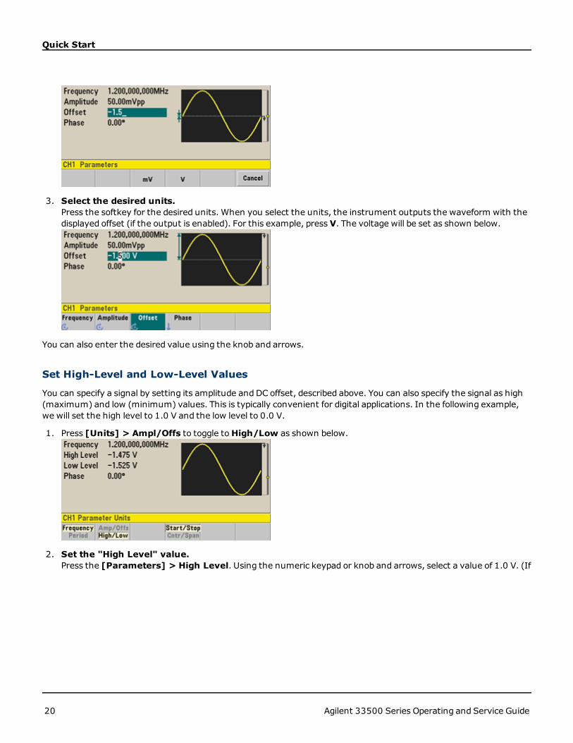
Quick Start
3. Select the desired units.Press the softkey for the desired units. When you select the units, the instrument outputs the waveform with thedisplayed offset (if the output is enabled). For this example, press V. The voltage will be set as shown below.
You can also enter the desired value using the knob and arrows.
Set High-Level and Low-Level Values
You can specify a signal by setting its amplitude and DC offset, described above. You can also specify the signal as high(maximum) and low (minimum) values. This is typically convenient for digital applications. In the following example,we will set the high level to 1.0 V and the low level to 0.0 V.
1. Press [Units] > Ampl/Offs to toggle toHigh/Low as shown below.
2. Set the "High Level" value.Press the [Parameters] > High Level. Using the numeric keypad or knob and arrows, select a value of 1.0 V. (If
20 Agilent 33500 Series Operating and Service Guide

Quick Start
you are using the keypad, you will need to select the V unit softkey to enter the value.)
3. Press the Low Level softkey and set the value.Again, use the numeric keypad or the knob to enter a value of 0.0 V.
These settings (high-level = 1.0 V and low-level = 0.0 V) are equivalent to setting an amplitude of 1.0 Vpp and an off-set of 500 mV.
Output a DC Voltage
You can output a constant DC voltage, from -5 V to +5 V into 50 Ω, or -10 V to +10 V into a high impedance load.
1. Press [Waveforms] > More > DC.TheOffset value becomes selected.
Agilent 33500 Series Operating and Service Guide 21

Quick Start
2. Enter the desired voltage offset.Enter 1.0 with the numeric keypad or knob, and press the V softkey if you used the keypad.
Set Duty Cycle of a Square Wave
The power-on default for square wave duty cycle is 50%. The duty cycle is limited by the minimum pulse width spec-ification of 16 ns. The following procedure changes the duty cycle to 75%.
1. Select the square wave function.Press [Waveforms] > Square.
2. Press theDuty Cycle softkey.The displayed duty cycle is either the power-on value or the percentage previously selected. The duty cycle rep-resents the amount of time per cycle that the square wave is at a high level.
3. Enter the desired duty cycle.Using the numeric keypad or the knob and arrows, select a duty cycle value of 75. If you are using the numeric key-pad, press Percent to finish the entry. The instrument adjusts the duty cycle immediately and outputs a squarewave with the specified value (if the output is enabled).
Configure a Pulse Waveform
You can configure the instrument to output a pulse waveform with variable pulse width and edge time. The followingsteps configure a 500 ms periodic pulse waveform with a pulse width of 10 ms and edge times of 50 ns.
22 Agilent 33500 Series Operating and Service Guide

Quick Start
1. Select the pulse function.Press [Waveforms] > Pulse to select the pulse function.
2. Set the pulse period.Press the [Units] key and then press Frequency/Period to choose Period. Then press [Parameters] >Period. Set the period to 500 ms.
3. Set the pulse width.Press [Parameters] > Pulse Width. Then set the pulse width to 10 ms. The pulse width represents the timefrom the 50% threshold of the rising edge to the 50% threshold of the next falling edge.
4. Set the edge time for both edges.Press the Edge Time softkey and then set the edge time for both the leading and trailing edges to 50 ns. The edgetime represents the time from the 10% threshold to the 90% threshold of each edge.
Select a Stored Arbitrary Waveform
There are nine built-in arbitrary waveforms stored in non-volatile memory. They are Cardiac, D-Lorentz, ExponentialFall, Exponential Rise, Gaussian, Haversine, Lorentz, Negative Ramp, and Sinc.
This procedure selects the built-in "exponential fall" waveform from the front panel. For information on creating a cus-tom arbitrary waveform, refer to Set Up Arbitrary Waveform.
Agilent 33500 Series Operating and Service Guide 23
Quick Start
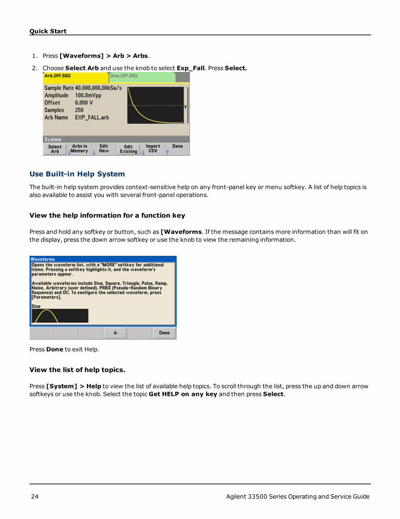
1. Press [Waveforms] > Arb > Arbs.
2. Choose Select Arb and use the knob to select Exp_Fall. Press Select.
Use Built-in Help System
The built-in help system provides context-sensitive help on any front-panel key or menu softkey. A list of help topics isalso available to assist you with several front-panel operations.
View the help information for a function key
Press and hold any softkey or button, such as [Waveforms. If the message contains more information than will fit onthe display, press the down arrow softkey or use the knob to view the remaining information.
PressDone to exit Help.
View the list of help topics.
Press [System] > Help to view the list of available help topics. To scroll through the list, press the up and down arrowsoftkeys or use the knob. Select the topicGet HELP on any key and then press Select.
24 Agilent 33500 Series Operating and Service Guide

Quick Start
PressDone to exit Help.
View the help information for displayed messages.
Whenever a limit is exceeded or any other invalid configuration is found, the instrument displays a message. The built-in help system provides additional information on the most recent message. Press [System] > Help. Then select thetopic View the last message displayed, and press Select.
PressDone to exit Help.
Local Language Help
All messages, context-sensitive help, and help topics are available in English, Chinese, French, Ger-man, Japanese, Korean, and Russian. The menu softkey labels and status line messages are nottranslated. To select the local language, press [System] > System Setup > User Settings> Help Lang. Then select the desired language.
Rack Mount the Instrument
You can mount the instrument in a standard 19-inch rack cabinet using one of two optional kits, each of which includesinstructions andmounting hardware. Any Agilent System II instrument of the same size can be rack-mounted besidethe instrument.
Remove the carrying handle, and the front and rear rubber bumpers, before rack-mounting theinstrument.
To remove the handle, rotate it to vertical and pull the ends outward.
Agilent 33500 Series Operating and Service Guide 25
Quick Start
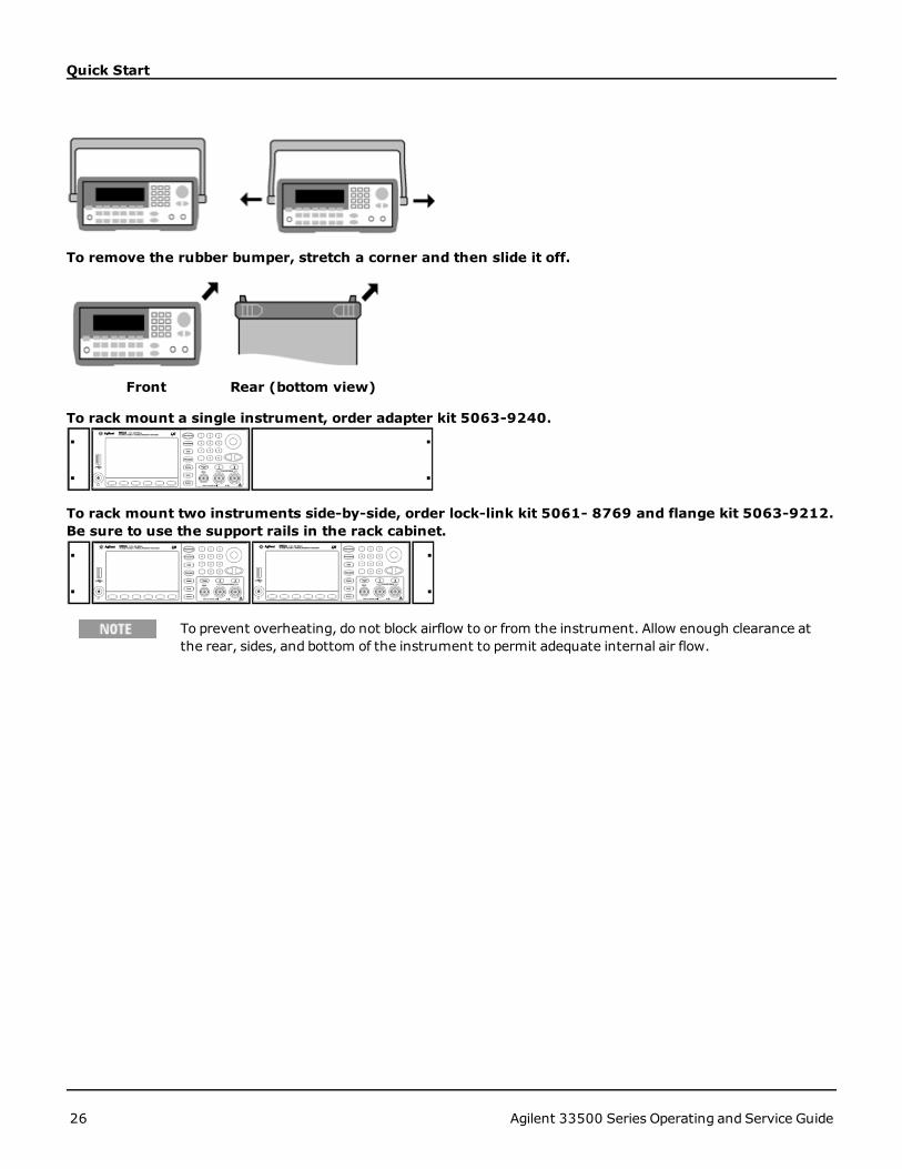
To remove the rubber bumper, stretch a corner and then slide it off.
Front Rear (bottom view)
To rack mount a single instrument, order adapter kit 5063-9240.
To rack mount two instruments side-by-side, order lock-link kit 5061- 8769 and flange kit 5063-9212.Be sure to use the support rails in the rack cabinet.
To prevent overheating, do not block airflow to or from the instrument. Allow enough clearance atthe rear, sides, and bottom of the instrument to permit adequate internal air flow.
26 Agilent 33500 Series Operating and Service Guide

Front-Panel Menu Operation Introduction
Front-Panel Menu Operation IntroductionThis section introduces front-panel keys andmenus. See Features and Functions for additional information.
l Front-Panel Menu Reference
l Select Output Termination
l Reset Instrument
l Output a ModulatedWaveform
l Output FSKWaveform
l Output PWMWaveform
l Output Frequency Sweep
l Output Burst Waveform
l Trigger Sweep or Burst
l Store Instrument State
l LAN Configuration Procedure
l Set Up Arbitrary Waveform
Select Output Termination
The instrument has a fixed series output impedance of 50 Ω to the front-panel channel connectors. If the actual loadimpedance differs from the value specified, the displayed amplitude and offset levels will be incorrect. The load imped-ance setting is simply a convenience to ensure that the displayed voltage matches the expected load.
1. Press a channel output key to open the channel configuration screen. Note that the current output terminationvalues (both 50 Ω in this case) appear on the tabs at the top of the screen.
2. Specify the output termination.
3. PressOutput Load.
4. Select the desired output termination.
5. Use the knob or numeric keypad to select the desired load impedance or press Set to 50 Ω or Set to High Z.
Reset Instrument
To reset the instrument to its factory default state, press [System] > Store/Recall > Set to Defaults.
Agilent 33500 Series Operating and Service Guide 27

Front-Panel Menu Operation Introduction
Output a Modulated Waveform
Amodulated waveform consists of a carrier waveform and amodulating waveform. In AM (amplitude modulation), thecarrier amplitude is varied by the modulating waveform. For this example, you will output an AM waveform with 80%modulation depth. The carrier will be a 5 kHz sine wave and the modulating waveform will be a 200 Hz sine wave.
1. Select the function, frequency, and carrier amplitude.
Press the [Waveforms] > Sine. Press the Frequency,Amplitude, andOffset softkeys to configure the carrierwaveform. For this example, select a 5 kHz sine wave with an amplitude of 5 Vpp, with 0 V offset.
Note that you may specify amplitude in Vpp, Vrms or dBm.
2. Select AM.PressModulate and then select "AM" using the Type softkey. Then pressModulate to turn modulation on.Notice that theModulate button is illuminated, and the status message "AM Modulated by Sine" appears at thetop left of the display.
3. Set the modulation depth.Press the AM Depth softkey and then set the value to 80% using the numeric keypad or the knob and arrows.
4. Select the modulating waveform shape.Press Shape to select the modulating waveform's shape. For this example, select a sine wave.
5. PressMore > AM Freq. Set the value to 200 Hz using the numeric keypad or the knob and arrows. PressHz to fin-ish entering the number if you are using the numeric keypad.
Output an FSK Waveform
You can configure the instrument to "shift" its output frequency between two preset values using FSKmodulation. Therate at which the output shifts between the two frequencies (called the "carrier frequency" and the "hop frequency") isdetermined by the internal rate generator or the signal level on the rear-panel Ext Trig connector. For this example,you will set the "carrier" frequency to 3 kHz and the "hop" frequency to 500 Hz, with an FSK rate of 100 Hz.
28 Agilent 33500 Series Operating and Service Guide

Front-Panel Menu Operation Introduction
1. Select the function, frequency, and carrier amplitude.
Press the [Waveforms] > Sine. Press the Frequency,Amplitude, andOffset softkeys to configure the carrierwaveform. For this example, select a 5 kHz sine wave with an amplitude of 5 Vpp, with 0 V offset.
2. Select FSK.PressModulate and then select FSK using the Type softkey. Then pressModulate to turn modulation on. Noticethe status message "FSK Modulated" at the top left of the display.
3. Set the "hop" frequency.Press theHop Freq softkey and then set the value to 500 Hz using the numeric keypad or the knob and arrows. Ifyou use the numeric keypad, be sure to finish the entry by pressingHz.
4. Set the FSK "shift" rate.Press the FSK Rate softkey and then set the value to 100 Hz using the numeric keypad or the knob and arrows.
At this point, the instrument outputs an FSK waveform.
Output PWM Waveform
You can configure the instrument to output a pulse width modulated (PWM)waveform. PWM is only available for thePulse waveform, and the pulse width varies according to the modulating signal. The amount by which the pulse widthvaries is called the width deviation, and it can be specified as a percentage of the waveform period (that is, duty cycle)or in units of time. For example, if you specify a pulse with 20% duty cycle and then enable PWMwith a 5% deviation,the duty cycle varies from 15% to 25% under control of the modulating signal.
To change from pulse width to pulse duty cycle, press [Units].
For this example, you will specify a pulse width and pulse width deviation for a 1 kHz pulse waveform with a 5Hz sinewave modulating waveform.
Agilent 33500 Series Operating and Service Guide 29

Front-Panel Menu Operation Introduction
1. Select the carrier waveform parameters.Press [Waveforms] > Pulse. Use the Frequency,Amplitude,Offset, Pulse Width and Edge Times soft-keys to configure the carrier waveform. For this example, select a 1 kHz pulse waveform with an amplitude of 1Vpp, zero offset, a pulse width of 100 µs, and an edge time of 50 ns (both leading and trailing).
2. Select PWM.PressModulate > Type > PWM. Then press the first softkey (Modulate) to turn modulation on. Notice thestatus message "PWMModulated by Sine" in the upper-left corner of the display.
3. Set the width deviation.Press theWidth Dev softkey and set the value to 20 µs using the numeric keypad or the knob and arrows.
4. Set the modulating frequency.Press the PWM Freq softkey and then set the value to 5 Hz using the numeric keypad or the knob and arrows.
5. Select the modulating waveform shape.Press Shape to select the modulating waveform's shape. For this example, select a sine wave.
To view the actual PWMwaveform, you would need to output it to an oscilloscope. If you do this, you will see how thepulse width varies, in this case, from 80 to 120 µs. At a modulation frequency of 5 Hz, the deviation is quite visible.
30 Agilent 33500 Series Operating and Service Guide

Front-Panel Menu Operation Introduction
Output Frequency Sweep
In the frequency sweepmode, the instrument moves from the start frequency to the stop frequency at a sweep rate,which you specify. You can sweep up or down in frequency, andwith either linear or logarithmic spacing, or using a listof frequencies. For this example, you will output a swept sine wave from 50 Hz to 5 kHz.
1. Select the function and amplitude for the sweep.For sweeps, you can select sine, square, ramp, pulse, triangle, or PRBS waveforms (arbitrary waveforms, noise,and DC are not allowed). For this example, select a sine wave with an amplitude of 5 Vpp.
2. Select the sweep mode.Press [Sweep] and verify that the linear sweepmode is currently selected on the second softkey. Press theSweep softkey to turn sweep on. Notice the Linear Sweep status message at the top of the tab for the currentchannel. The button is also illuminated.
3. Set the start frequency.Press Start Freq and then set the value to 50 Hz using the numeric keypad or the knob and arrows.
Agilent 33500 Series Operating and Service Guide 31

Front-Panel Menu Operation Introduction
4. Set the stop frequency.Press Stop Freq and set the value to 5 kHz using the numeric keypad or the knob and arrows.
At this point, the instrument outputs a continuous sweep from 50 Hz to 5 kHz if output is enabled.
You can also set the sweep frequency boundaries of the sweep using a center frequency and frequency span. Theseparameters are similar to the start frequency and stop frequency (above) and they provide added flexibility. To achievethe same results, set the center frequency to 2.525 kHz and the frequency span to 4.950 kHz.
To generate a frequency sweep, press [Trigger] twice. The first press puts the trigger in manual mode, and the secondone sends a trigger. For more information, see Trigger Sweep or Burst.
Output Burst Waveform
You can configure the instrument to output a waveform with for a specified number of cycles, called a burst. You cancontrol the amount of time that elapses between bursts with the internal timer or the signal level on the rear-panel ExtTrig connector. For this example, you will output a three-cycle sine wave with a 20 ms burst period.
1. Select the function and amplitude for the burst.For burst waveforms, you can select sine, square, ramp, pulse, arbitrary waveforms, triangle, or PRBS. Noise isallowed only in the "gated" burst mode and DC is not allowed. For this example, select a sine wave with an ampli-tude of 5 Vpp.
32 Agilent 33500 Series Operating and Service Guide

Front-Panel Menu Operation Introduction
2. Select the burst mode.Press [Burst] > Burst Off/On. Notice that a status messageN Cycle Burst, Trig Imm is shown in the tab ofthe current channel.
3. Set the burst count.Press# of Cycles and set the count to "3" using the numeric keypad or knob. Press Enter to finish data entry ifyou are using the numeric keypad.
4. Set the burst period.Press Burst Period and set the period to 20 ms using the numeric keypad or the knob and arrows. The burstperiod sets the time from the start of one burst to the start of the next burst. At this point, the instrument outputsa continuous three-cycle burst at 20 ms intervals.
You can generate a single burst (with the specified count) by pressing the [Trigger] key. For more information, seeTrigger Sweep or Burst.
You can also use the external gate signal to create gated bursts, where a burst is producedwhile a gate signal is presenton the input.
Trigger Sweep or Burst
You can issue four different types of triggers from the front panel for sweeps and bursts:
Agilent 33500 Series Operating and Service Guide 33

Front-Panel Menu Operation Introduction
l Immediate or "automatic" (default): instrument outputs continuously when sweep or burst mode is selected.
l External: triggering controlled by rear panel Ext Trig connector.
l Manual: initiates one sweep or burst each time you press [Trigger]. Continue pressing [Trigger] to re-triggerinstrument.
l Timer: issues one or more triggers a fixed time amount apart.
If sweep or burst is on, pressing [Trigger] displays the trigger menu. An illuminated [Trigger] key (solid or blinking)indicates that one or both channels are in awaiting a manual trigger. Solid illumination occurs when trigger menu isselected, and flashing illumination occurs when trigger menu is not selected. The [Trigger] key is disabled when instru-ment is in remote.
Pressing [Trigger] when it is solidly illuminated causes a manual trigger. Pressing [Trigger] when it is flashing selectsthe trigger menu; a second press causes a manual trigger.
Store Instrument State
You can store instrument states in any number of state files, (extension .sta). You can do this for backup purposes, oryou can save your state to a USB drive and load it on another instrument to have instruments with matching con-figurations. A stored state contains the selected function, frequency, amplitude, DC offset, duty cycle, symmetry, andany modulation parameters in use. The instrument does not store volatile arbitrary waveforms.
1. Select the desired storage location.
2. Specify the name for the selected location.
To add characters, press the right-cursor key until the cursor is to the right of the existing name and then turn theknob. To delete a character, rotate the knob until you get to the blank character before the capital A. To delete allcharacters from the cursor position to the end of the line, press [+/-]. You can enter numbers directly from thenumeric keypad.
3. Store the instrument state.
34 Agilent 33500 Series Operating and Service Guide

Front-Panel Menu Operation Introduction
To restore (retrieve) a stored state:
Agilent 33500 Series Operating and Service Guide 35

Front-Panel Menu Reference
Front-Panel Menu ReferenceOverview of the front-panel menus. The remainder of this chapter contains examples of using the front-panel menus.
Selects waveform
l Sine
l Square
l Ramp
l Pulse
l Arbitrary
l Triangle
l Noise
l PRBS
l DC
Configures waveform-specific parameters
l Period/Frequency
l Amplitude or High and Low Voltage
l Offset
l Phase
l Duty Cycle
l Symmetry
l Pulse Width
l Edge Time
l Arbitrary Waveform
l Bandwidth
36 Agilent 33500 Series Operating and Service Guide

Front-Panel Menu Reference
l PRBS Data
l Bit Rate
Specifies unit and parameter preferences
l Frequency or Period
l Voltage as Amplitude/Offset or High/Low
l Voltage units
l Pulse Width or Duty Cycle
l Frequency sweep as Center/Span or Start/Stop
Configures modulation parameters
l Modulation on or off
l Modulation type: AM, FM, PM, PWM, BPSK, FSK, or Sum
l Modulation source
l Modulation parameters
Configures frequency sweep parameters
l Sweep on or off
l Linear, logarithmic or frequency list
l Sweep time
Agilent 33500 Series Operating and Service Guide 37

Front-Panel Menu Reference
l Start/stop frequencies or center/span frequencies
l Dwell, hold, and return times
Configures burst parameters
l Burst on or off
l Burst mode: triggered (N Cycle) or externally-gated
l Cycles per burst (1 to 100,000,000 or infinite)
l Starting phase angle of burst (-360° to +360°)
l Burst period
Stores and recalls instrument states
l Store instrument states in non-volatile memory.
l Assign custom names to storage locations.
l Recall stored instrument states.
l Delete stored instrument states.
l Restore all instrument settings to their factory default values.
l Select the instrument’s power-on configuration (last power-down or factory default).
38 Agilent 33500 Series Operating and Service Guide

Front-Panel Menu Reference
Configures instrument I/O interfaces
l Turn LAN on and off
l Configure LAN (IP address and network configuration)
l Reset the LAN.
l Specify USB settings
l Select GPIB address
Configures instrument parameters
l Calibrate instrument
l Perform self-test
l Configure reference oscillator
l Clear instrument memory (NISPOM secure)
Configures system-related parameters
l Set screen layout
l Select local language for front-panel messages and help text
l Select how periods and commas are used in numbers on display
l Turn display on and off
l Enable or disable error beeper
l Enable or disable screen saver
l Adjust display brightness
l Install licensed features
Agilent 33500 Series Operating and Service Guide 39

Front-Panel Menu Reference
l Set date and time
l Manage files and folders (copy, rename, delete, and so on)
l Capture screen shots.
Shows list of Help topics
l View last message displayed.
l View remote command error queue.
l Get help on any key.
l Learn how to obtain technical support.
l View "about" data - serial number, IP address, firmware version, and so on.
Enables and configures channels
l Turn channel on and off.
l Specify which channel is the focus of the menus.
l Select output termination (1 Ω to 10 kΩ, or Infinite).
l Enable / disable amplitude autoranging.
l Select waveform polarity (normal or inverted).
l Specify voltage limits.
l Specify whether output is normal or gated.
l Configure dual channel operation.
40 Agilent 33500 Series Operating and Service Guide

Front-Panel Menu Reference
Configures trigger settings
l Perform amanual trigger, when illuminated.
l Specify the trigger source for sweep, burst or arbitrary waveform advance.
l Specify the trigger count and delay.
l Specify the slope (rising or falling edge) for an external trigger source.
l Specify the slope (rising or falling edge) of the trigger output signal.
l Enable / disable the signal output from the "Sync" connector.
Agilent 33500 Series Operating and Service Guide 41
LAN Configuration Procedure
LAN Configuration ProcedureThere are several parameters that you might need to set to establish network communication using the LAN interface.Primarily, you will need to establish an IP address. You might need to contact your network administrator for help inestablishing communication with the LAN interface.
1. Select the "I/O" menu.Press [System] > I/O Config.
2. Select the LAN Settings menu.Press the LAN Settings softkey.
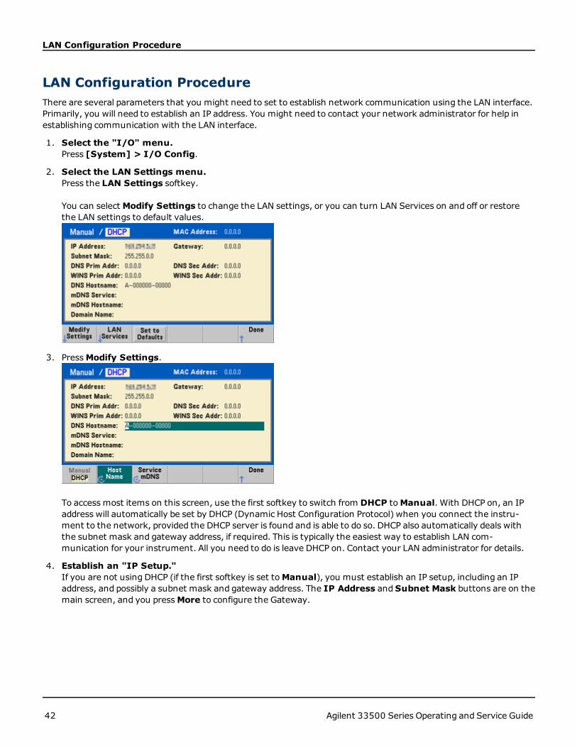
You can selectModify Settings to change the LAN settings, or you can turn LAN Services on and off or restorethe LAN settings to default values.
3. PressModify Settings.
To access most items on this screen, use the first softkey to switch from DHCP toManual. With DHCP on, an IPaddress will automatically be set by DHCP (Dynamic Host Configuration Protocol) when you connect the instru-ment to the network, provided the DHCP server is found and is able to do so. DHCP also automatically deals withthe subnet mask and gateway address, if required. This is typically the easiest way to establish LAN com-munication for your instrument. All you need to do is leave DHCP on. Contact your LAN administrator for details.
4. Establish an "IP Setup."If you are not using DHCP (if the first softkey is set toManual), you must establish an IP setup, including an IPaddress, and possibly a subnet mask and gateway address. The IP Address andSubnet Mask buttons are on themain screen, and you pressMore to configure the Gateway.
42 Agilent 33500 Series Operating and Service Guide

LAN Configuration Procedure
Contact your network administrator for the IP address, subnet mask, and gateway to use. All IP addresses take thedot-notation form "nnn.nnn.nnn.nnn" where "nnn" in each case is a byte value in the range 0 through 255. Youcan enter a new IP address using the numeric keypad (not the knob). Just type in the numbers and the perioddelimiters using the keypad. Use the left cursor key as a backspace key. Do not enter leading zeros.
5. Configure the "DNS Setup" (optional)DNS (Domain Name Service) is an Internet service that translates domain names into IP addresses. Ask your net-work administrator whether DNS is in use, and if it is, for the host name, domain name, and DNS server address touse.
a. Set the "hostname." PressHost Name and enter the hostname. A hostname is the host portion of thedomain name, which is translated into an IP address. The hostname is entered as a string using the knob andcursor keys to select and change characters. The hostnamemay include letters, numbers, and dashes ("-").You can use the keypad for the numeric characters only.
b. Set the "DNS Server" addresses. From the LAN configuration screen, pressMore to go to the second of threesets of softkeys.
Enter the Primary DNS and Second DNS. See your network administrator for details.
More about IP Addresses and Dot Notation
Dot-notation addresses ("nnn.nnn.nnn.nnn" where "nnn" is a byte value from 0 to 255)must be expressedwith care,as most PC web software interprets byte values with leading zeros as octal (base 8) numbers. For example,"192.168.020.011" is actually equivalent to decimal "192.168.16.9" because ".020" is interpreted as "16" expressedin octal, and ".011" as "9". To avoid confusion, use only decimal values from 0 to 255, with no leading zeros.
Agilent 33500 Series Operating and Service Guide 43

Set Up Arbitrary Waveform
Set Up Arbitrary WaveformThe instrument includes an embeddedwaveform editor that allows you to create and edit arbitrary waveforms. You cancreate these waveforms by editing voltage values directly or by using an combination of up to 12 different kinds ofstandard waveforms.
The following tutorial creates and edits a basic waveform.
Insert Built-in Waveforms
1. Start the embeddedwaveform editor by pressing [Waveforms] > Arb > Arbs. Press Edit New, accept thedefault file name, and then Start Editor. You now have a 0 VDCwaveform of exactly 8 points.
2. Press Insert Built-in > Choose Wave. Use the knob or the arrows below the knob to select D-Lorentz andpressOK. Use the keypad and the V softkey that appears when you start typing on the keypad to set the Ampli-tude to 2 V, and then pressOK. The waveform now has 108 points, as the D-Lorentz waveform of 100 points wasinserted in front of the initial 8 points.
3. Suppose that you want to undo the change that you just made. Press [System] > Undo. You are now back tothe original 8 point, 0 V waveform.
44 Agilent 33500 Series Operating and Service Guide

Set Up Arbitrary Waveform
4. To put the D-Lorentz waveform back, pressRedo. Then pressDone to exit.
5. Now we will insert a sine wave. Begin by pressingChoose Wave. Make sure Sine (the default) is highlighted, andpressOK. For help in understanding the various parameters on the screen, press Parameter Help. Then pressDone to exit the help screen.
6. Using the numeric keypad and the up and down arrow softkeys, set the Amplitude to 3.5 V, the Cycles to 4, andthe Points to 200. Leave all other settings at their default values and pressOK.
Agilent 33500 Series Operating and Service Guide 45

Set Up Arbitrary Waveform
7. Notice that the first softkey, Select Point # is highlighted. Put the marker on the 270th waveform point by usingthe numeric keypad to enter the number 270 and pressing Enter.
8. Press Choose Wave, select Square, and then pressOK. Set the Amplitude to 3 V, the Offset to -2 V, the Cyclesto 8, and the Points to 100. PressOK. Notice that the 8 square wave cycles have been inserted, beginning at themarker. PressDone.
Edit Waveform Characteristics
1. Press Edit Params and then set the Sampling Rate to 100 Sa/s. Press Cycle Period and notice that it has beenset to 4.08 seconds. This is because you have 408 sample points in the waveform, and the sample rate is 100Sa/s.
46 Agilent 33500 Series Operating and Service Guide
Set Up Arbitrary Waveform
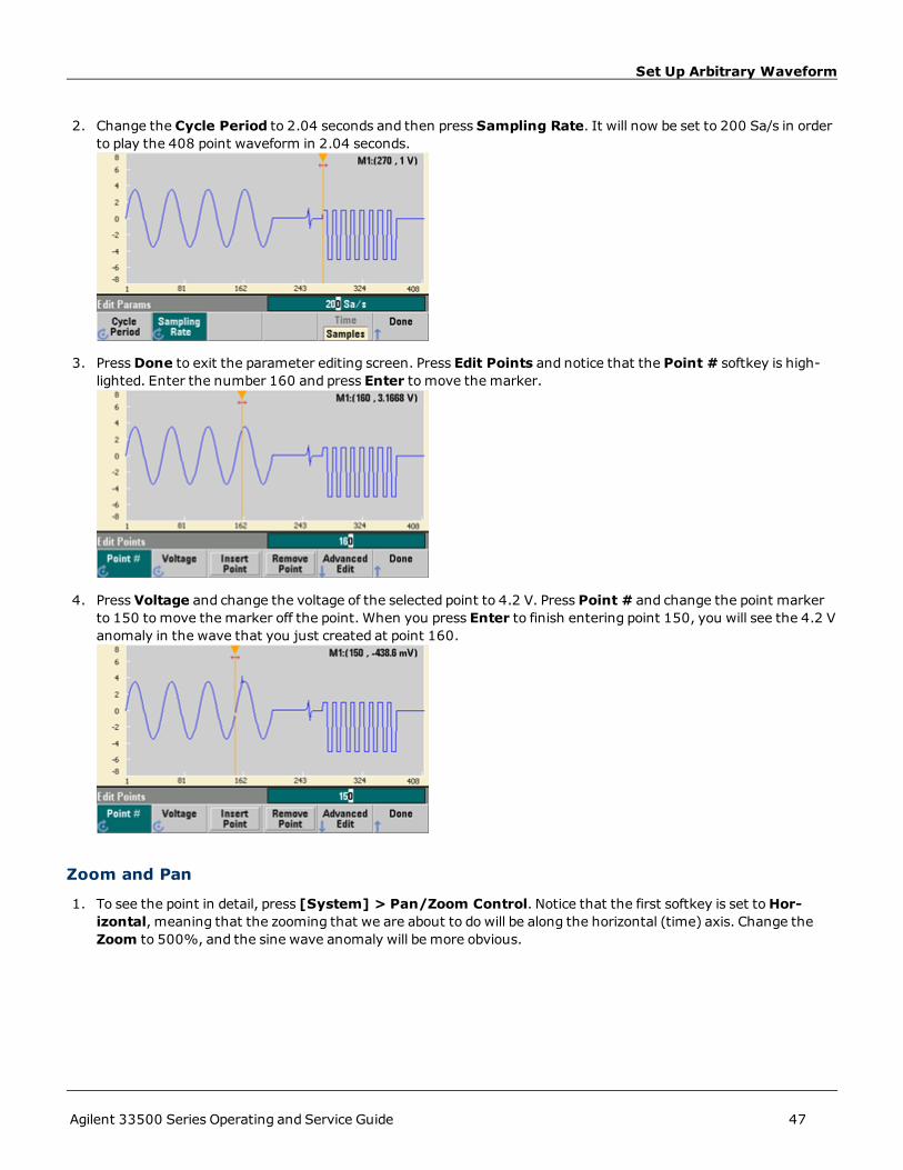
2. Change the Cycle Period to 2.04 seconds and then press Sampling Rate. It will now be set to 200 Sa/s in orderto play the 408 point waveform in 2.04 seconds.
3. PressDone to exit the parameter editing screen. Press Edit Points and notice that the Point # softkey is high-lighted. Enter the number 160 and press Enter to move the marker.
4. Press Voltage and change the voltage of the selected point to 4.2 V. Press Point # and change the point markerto 150 tomove the marker off the point. When you press Enter to finish entering point 150, you will see the 4.2 Vanomaly in the wave that you just created at point 160.
Zoom and Pan
1. To see the point in detail, press [System] > Pan/Zoom Control. Notice that the first softkey is set toHor-izontal, meaning that the zooming that we are about to do will be along the horizontal (time) axis. Change theZoom to 500%, and the sine wave anomaly will be more obvious.
Agilent 33500 Series Operating and Service Guide 47

Set Up Arbitrary Waveform
2. Now set the first softkey toVertical to zoom vertically. Set the Zoom to 500%. Notice that we have zoomed in onthe voltage axis, but we are too low to see the 4.2 V anomaly in the sine wave.
3. Press Pan and set the Pan to 3 V in order to move higher on the waveform. The 4.2 V point is now clearly visible.
4. To see the entire waveform again, press Show All. Then pressDone andDone again to return to the EditPoints screen.
48 Agilent 33500 Series Operating and Service Guide

Set Up Arbitrary Waveform
Insert, Remove, Copy and Paste Points
1. Press Insert Point 15 times andwatch the display carefully. You will see 15 new waveform points at the samevoltage level.
2. Change the Point # to 220 and pressRemove Point 20 times, watching the display carefully as you do so inorder to see the points being removed from the waveform.
3. You can also edit points by using a table of voltages. PressAdvanced Edit > Edit Via Table. Set Point # to 200,and then set the Voltage for point 200 to 3 V. Use the knob tomove between rows and set the Voltage for points205 and 210 to 3 V. PressDone.
Agilent 33500 Series Operating and Service Guide 49

Set Up Arbitrary Waveform
4. Notice the three 3 V spikes that you just made in the waveform at points 200, 205, and 210.
5. Press Cut/Copy Paste, and setMarker 1 to 150. Then press the first softkey and change theMarker toMarker2. SetMarker 2 to 300. The range defined by the markers is now highlighted in black.
6. Press Copy, then Paste, and then At Start. Notice that section you copied is now duplicated at the beginning ofthe waveform.
7. Now press Paste > At End. The same section of the waveform now also appears at the very end.
50 Agilent 33500 Series Operating and Service Guide

Set Up Arbitrary Waveform
8. Now press Paste and change the Point # to 500. Then pressOK, and the same portion of the waveform will bepasted in at point 500. PressDone to leave the Cut/Copy Pastemenu.
Perform Math
The embeddedwaveform editor allows you to perform mathematical operations on the waveform. First you setmarkers to define the range of the waveform that you want to modify. You can then add, subtract or multiply that por-tion of the waveform by another waveform, or you can transform the waveform in ways that do not involve other wave-forms.
1. Press Perform Math. SetMarker 1 to 400 andMarker 2 to 500.
2. PressAdd, then select Haversine andOK. Set the Amplitude to 3 V, the Offset to 0 V, and pressOK. Notice thatthe highlighted section now rises in the middle as a result of theHaversine addition.
Agilent 33500 Series Operating and Service Guide 51

Set Up Arbitrary Waveform
3. Now pressMultiply and select the Sine wave (pressOK). Set the Cycles to 2 and pressOK.
4. Now setMarker 1 to 200 andMarker 2 to 600.
5. PressAdvanced Math > Mirror > OK.
6. Continue learning about the interface by trying other Advanced Math features, such as Invert,Absolute, Scale,and so on. PressOperation Help for more information.
52 Agilent 33500 Series Operating and Service Guide

Features and Functions
Features and FunctionsThis section contains details on instrument features, including front panel and remote interface operation. You maywant to read Front-Panel Menu Reference first. See SCPI Programming Reference for details on SCPI commands andqueries. This section covers:
Output Configuration
Pulse Waveforms
Amplitude Modulation (AM) and Frequency Modulation (FM)
Phase Modulation (PM)
Frequency-Shift Keying (FSK) Modulation
Pulse Width Modulation (PWM)
Sum Modulation
Frequency Sweep
Burst Mode
Triggering
Dual Channel Operations
System-Related Operations
Remote Interface Configuration
External Timebase Reference
EmbeddedWaveform Editor
Throughout this document, "default" states and values are identified. These are the power-on default states providedyou have not enabled the power-down recall mode (see Instrument State Storage).
Agilent 33500 Series Operating and Service Guide 53

Output Configuration
Output ConfigurationThis section describes output channel configuration. Many commands associated with output configuration start withSOURce1: or SOURce2: to indicate a certain channel. If omitted, the default is channel 1. For example, VOLT 2.5 setsthe output on channel 1 to 2.5 V, and SOUR2:VOLT 2.5 does the same for channel 2.
The instrument's display includes a "tab" for each channel that summarizes various aspects of each channel's outputconfiguration:
On a two-channel instrument, the tab for channel 1 will be yellow, and the tab for channel 2 will be green.
Output Function
The instrument includes eight standard waveforms: sine, square, ramp, pulse, triangle, noise, PRBS (pseudo-randombinary sequence), and DC. There are also nine built-in arbitrary waveforms, and you can create custom waveformswith the embeddedwaveform editor.
The table below shows which functions are allowed (•) with modulation, sweep, and burst. Selecting a function that isnot allowedwith a modulation or mode disables the modulation or mode.
Carrier AM FM PM FSK BPSK PWM Sum Burst Sweep
Sine and Square • • • • • • • •
Pulse • • • • • • • • •
Triangle and Ramp • • • • • • • •
Gaussian Noise • • •a
PRBS • • • • •
Arbitrary Waveform • • •b •b • • •
Sequence • •
(a) Gated burst only
(b) Applies to sample clock, not whole waveform
l Frequency Limitations: Changing functions may change the frequency tomeet the new function's frequency lim-its.
l Amplitude Limitations:When the output units are Vrms or dBm, changing functions may lower the amplitude tothe maximum for the new function due to variation in waveform shapes. For example, a 5 Vrms square wave (into50 Ω) changed to a sine will decrease to 3.536 Vrms (sine’s upper limit).
l Amplitude and offset cannot combine to exceed the instrument’s capability. The one you set last may be changedto stay within limits.
l You may protect a device under test (DUT) by specifying upper and lower output voltage limits.
l Front Panel:
54 Agilent 33500 Series Operating and Service Guide
Output Configuration
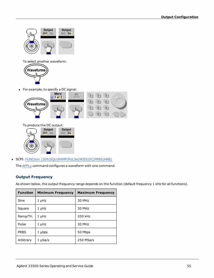
To select another waveform:
l For example, to specify a DC signal:
To produce the DC output:
l SCPI: FUNCtion {SIN|SQU|RAMP|PULSe|NOIS|DC|PRBS|ARB}
The APPLy command configures a waveform with one command.
Output Frequency
As shown below, the output frequency range depends on the function (default frequency 1 kHz for all functions).
Function Minimum Frequency Maximum Frequency
Sine 1 µHz 30 MHz
Square 1 µHz 30 MHz
Ramp/Tri. 1 µHz 200 kHz
Pulse 1 µHz 30 MHz
PRBS 1 µbps 50 Mbps
Arbitrary 1 µSa/s 250 MSa/s
Agilent 33500 Series Operating and Service Guide 55

Output Configuration
l Frequency Limitations: Changing functions may change the frequency tomeet the new function's frequency lim-its.
l Burst Limitation: For internally-triggered bursts, the minimum frequency is 126 µHz.
l Duty Cycle Limitations: For Square and Pulse, Duty Cycle is limited by the 16-ns minimum pulse width spec-ification. For example, at 1 kHz, Duty Cycle may be set as low as 0.01%, because that would result in a pulse widthof 100 ns. At 1 MHz, the minimum Duty Cycle is 1.6%, and at 10 MHz it is 16%. Changing to a frequency that can-not produce the current duty cycle will adjust the duty cycle to meet the minimum pulse width specification.
l Front Panel:
l You can also toggle to the setting to Period.
l SCPI: [SOURce[1|2]:]FREQuency {<frequency>|MIN|MAX}
The APPLy command configures a waveform with one command.
Output Amplitude
The default amplitude is 100 mVpp (into 50 Ω) for all functions.
l Offset Voltage Limitations: The relationship between amplitude and offset is shown below. Vmax is ±5 V for a 50 Ωload or ±10 V for a high-impedance load).
Vpp< 2(Vmax – |Voffset|)
l Limits Due to Output Termination: If the amplitude is 10 Vpp and you change the output termination setting from50 Ω to "high impedance" (OUTPut[1|2]:LOAD INF), the displayed amplitude doubles to 20 Vpp. Changing from"high impedance" to 50 Ω halves the displayed amplitude. The output termination setting does not affect theactual output voltage; it only changes the values displayed and queried from the remote interface. Actual outputvoltage depends on the connected load.
l Limits Due to Units Selection:Amplitude limits are sometimes determined by the output units selected. This mayoccur when the units are Vrms or dBm due to the differences in various functions' crest factors. For example, ifyou change a 5 Vrms square wave (into 50 Ω) to a sine wave, the instrument will adjust the amplitude to 3.536Vrms (the upper limit for sine in Vrms). The remote interface will also generate a "Settings conflict" error.
l You can set the output amplitude in Vpp, Vrms, or dBm. You cannot specify output amplitude in dBm if output ter-mination is set to high impedance. See Output Units for details.
l Arbitrary Waveform Limitations: For arbitrary waveforms, amplitude is limited if the waveform data points do notspan the full range of the output DAC (Digital-to-Analog Converter). For example, the built-in "Sinc" waveformdoes not use the full range of values, so its maximum amplitude is limited to 6.087 Vpp (into 50 Ω).
l Changing amplitude may briefly disrupt output at certain voltages due to output attenuator switching. The ampli-tude is controlled, however, so the output voltage will never exceed the current setting while switching ranges. Toprevent this disruption, disable voltage autoranging using VOLTage:RANGe:AUTOOFF. The APPLy command auto-matically enables autoranging.
56 Agilent 33500 Series Operating and Service Guide

Output Configuration
l Setting the high and low levels also sets the waveform amplitude and offset. For example, if you set the high levelto +2 V and the low level to -3 V, the resulting amplitude is 5 Vpp, with a -500 mV offset.
l A DC signal's output level is controlled by the offset voltage (DC Offset Voltage). The DC level may be between ±5 Vinto a 50 Ω load or ±10 V with a high-impedance load.
l Front Panel:
To use a high level and low level instead:
l SCPI:VOLTage {<amplitude>|MINimum|MAXimum}
VOLTage:HIGH {<voltage>|MINimum|MAXimum}
VOLTage:LOW {<voltage>|MINimum|MAXimum}
The APPLy command configures a waveform with one command.
DC Offset Voltage
The default offset is 0 V for all functions.
l Limits Due to Amplitude: The relationship between offset voltage and output amplitude is shown below. The peakoutput voltage (DC plus AC) cannot exceed the instrument output rating (±5 V into 50 Ω load, or ±10 V into anopen circuit).
l The relationship between offset voltage and output amplitude is shown below. Vmax is the maximum peak voltagefor the selected output termination (5 V for a 50 Ω load or 10 V for a high-impedance load).
|Voffset| < Vmax - Vpp/2
If the specified offset voltage is not valid, the instrument will adjust it to the maximum DC voltage allowedwith thespecified amplitude. From the remote interface, a "Data out of range" error will also be generated.
l Limits Due to Output Termination: The offset range depends on the output termination setting. For example, ifyou set offset to 100 mVDC and then change output termination from 50 Ω to "high impedance," the offset volt-age displayed on the front panel doubles to 200 mVDC (no error is generated). If you change from "high imped-ance" to 50 Ω, the displayed offset voltage will be halved. See OUTPut[1|2]:LOAD for details. Changing the outputtermination setting does not change the voltage present at the output terminals of the instrument. This onlychanges the displayed values on the front panel and the values queried from the remote interface. The voltage
Agilent 33500 Series Operating and Service Guide 57

Output Configuration
present at the instrument's output depends on the load connected to the instrument. See OUTPut[1|2]:LOAD fordetails.
l Arbitrary Waveform Limitations: For arbitrary waveforms, amplitude is limited if the waveform data points do notspan the full range of the output DAC (Digital-to-Analog Converter). For example, the built-in "Sinc" waveformdoes not use the full range of values, so its maximum amplitude is limited to 6.087 Vpp (into 50 Ω).
l Setting the high and low levels also sets the waveform amplitude and offset. For example, if you set the high levelto +2 V and the low level to -3 V, the resulting amplitude is 5 Vpp, with a -500 mV offset.
l To output a DC voltage level, select the DC voltage function (FUNCtion DC) and then set the offset voltage (VOLT-age:OFFSet). Valid values are between ±5 VDC into 50 Ω or ±10 VDC into an open circuit. While the instrument isin DCmode, setting amplitude has no effect.
l Front Panel:
l SCPI:[SOURce[1|2]:]VOLTage:OFFSet {<offset>|MIN|MAX}
[SOURce[1|2]:]VOLTage:HIGH {<voltage>|MIN|MAX}
[SOURce[1|2]:]VOLTage:LOW {<voltage>|MIN|MAX}
The APPLy command configures a waveform with one command.
Output Units
Applies to output amplitude only.
l Output units: Vpp (default), Vrms, or dBm.
l Setting is volatile.
l Units selection applies to front panel and remote interface operations. For example, if you select "VRMS" remotely,the units are displayed as "VRMS" on front panel.
l Amplitude units cannot be dBm if output termination set to high impedance. Calculating dBm requires finite loadimpedance. In this case, units are converted to Vpp.
l You can convert between units. For example, to convert 2 Vpp to Vrms equivalent:
The converted value is 707.1 mVrms for a sine wave.
58 Agilent 33500 Series Operating and Service Guide

Output Configuration
l Front Panel:
l SCPI: VOLTage:UNIT {VPP|VRMS|DBM}
Output Termination
The instrument has a fixed series output impedance of 50 Ω to the front-panel channel connectors. If the actual loadimpedance differs from the value specified, the displayed amplitude and offset levels will be incorrect. The load imped-ance setting is simply a convenience to ensure that the displayed voltage matches the expected load.
l Output termination: 1 Ω to 10 kΩ, or infinite. The default is 50 Ω. The tab at the top of each channel indicates thevalue of this setting.
l If you specify a 50 Ω termination but actually terminate into an open circuit, the output will be twice the valuespecified. For example, if you set the DC offset to 100 mVDC (and specify a 50 Ω load) but terminate into an opencircuit, the actual offset will be 200 mVDC.
l Changing output termination setting, adjusts displayed output amplitude and offset (no error is generated). If theamplitude is 10 Vpp and you change the output termination setting from 50 Ω to "high impedance" (OUTPut[1|2]:LOAD INF), the displayed amplitude doubles to 20 Vpp. Changing from "high impedance" to 50 Ω halves thedisplayed amplitude. The output termination setting does not affect the actual output voltage; it only changes thevalues displayed and queried from the remote interface. Actual output voltage depends on the connected load.
l Units are converted to Vpp if output termination is high impedance.
l You cannot change output termination with voltage limits enabled, because instrument cannot know which ter-mination setting the limits apply to. Instead, disable voltage limits, set the new termination value, adjust voltagelimits, and re-enable voltage limits.
l Front Panel:
l SCPI: OUTPut[1|2]:LOAD {<ohms>|INFinity|MIN|MAX}
Duty Cycle (Square Waves)
A square wave’s duty cycle is the fraction of time per cycle that the waveform is at a high level (assuming the waveformis not inverted). (See Pulse Waveforms for pulse duty cycle details.)
Agilent 33500 Series Operating and Service Guide 59
Output Configuration
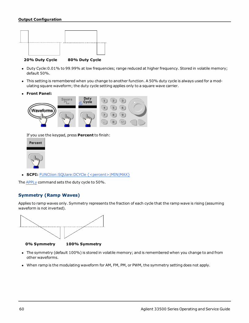
20% Duty Cycle 80% Duty Cycle
l Duty Cycle:0.01% to 99.99% at low frequencies; range reduced at higher frequency. Stored in volatile memory;default 50%.
l This setting is rememberedwhen you change to another function. A 50% duty cycle is always used for a mod-ulating square waveform; the duty cycle setting applies only to a square wave carrier.
l Front Panel:
If you use the keypad, press Percent to finish:
l SCPI: FUNCtion:SQUare:DCYCle {<percent>|MIN|MAX}
The APPLy command sets the duty cycle to 50%.
Symmetry (Ramp Waves)
Applies to rampwaves only. Symmetry represents the fraction of each cycle that the rampwave is rising (assumingwaveform is not inverted).
0% Symmetry 100% Symmetry
l The symmetry (default 100%) is stored in volatile memory; and is rememberedwhen you change to and fromother waveforms.
l When ramp is the modulating waveform for AM, FM, PM, or PWM, the symmetry setting does not apply.
60 Agilent 33500 Series Operating and Service Guide

Output Configuration
l Front Panel:
Then choose one of the following options. The Symmetry option allows you to use the knob or keypad to specify avalue.
If you use the keypad, press Percent to finish:
l SCPI: FUNCtion:RAMP:SYMMetry {<percent>|MIN|MAX}
The APPLy command sets the symmetry to 100%.
Voltage Autoranging
Autoranging is enabled by default and the instrument selects optimal attenuator settings. With autoranging disabled,the instrument uses the current attenuator settings and does not switch attenuator relays.
l You can disable autoranging to eliminate momentary disruptions caused by attenuator switching while changingamplitude. However:
l The amplitude and offset accuracy and resolution (andwaveform fidelity)may be adversely affected when reduc-ing the amplitude below a range change that would occur with autoranging on.
l You may not achieve minimum amplitude with autoranging on.
l Some instrument specifications do not apply with autoranging off.
l Front Panel:
Agilent 33500 Series Operating and Service Guide 61

Output Configuration
or
l SCPI: VOLTage:RANGe:AUTO {OFF|ON|ONCE}
The APPLy command always enables autoranging.
Output Control
By default, channel output is disabled at power on to protect other equipment. To enable a channel's output, see below.When channel output is enabled, the corresponding channel button is lit.
l If an external circuit applies excessive voltage to a channel output connector, the instrument generates an errormessage and disables the output. To re-enable output, remove the overload and turn the channel on again.
l Front Panel:
l SCPI: OUTPut[1|2] {OFF|ON}
The APPLy command always enables the channel output connector.
Waveform Polarity
In normal mode (default), the waveform goes positive at the beginning of the cycle. Invertedmode does the opposite.
l As shown below, the waveform is inverted relative to the offset voltage. The offset voltage remains unchangedwhen the waveform is inverted.
No Offset Voltage With Offset Voltage
l The Sync signal associated with an inverted waveform is not inverted.
62 Agilent 33500 Series Operating and Service Guide

Output Configuration
l Front Panel:
or
l SCPI: OUTPut[1|2]:POLarity {NORMal|INVerted}
Sync Output Signal
A sync output is provided on the front-panel Sync connector. All of the standard output functions (except DC andnoise) have an associatedSync signal. For applications where you may not want to output the Sync signal, you candisable the Sync connector. The Sync signal may be derived from either output channel in a two-channel instrument.
General Behavior
l By default, the Sync signal is derived from channel 1 and is routed to the Sync connector (enabled).
l When the Sync signal is disabled, the output level on the Sync connector is at a logic "low."
l The polarity of the Sync signal is specified by OUTPut:SYNC:POLarity {INVerted|NORMal}.
l Inverting a waveform (see Waveform Polarity), does not invert the associatedSync signal .
l For sine, pulse, ramp, square, and triangle waves, the Sync signal is a square wave that is "high" in the first half ofthe cycle and "low" in the last half. The Sync signal’s voltages are TTL-compatible when its load impedanceexceeds 1 kΩ.
l For arbitrary waveforms, the Sync signal rises at the beginning of the waveform and falls at the middle of the arbi-trary waveform. You can override this default behavior by usingMARKer:POINt to specify the point within the arbi-trary waveform at which the Sync signal transitions to "low."
Modulation
l For internally-modulated AM, FM, PM, and PWM, the Sync signal is normally referenced to the modulating wave-form (not the carrier) and is a square waveform with a 50% duty cycle. The Sync signal is a TTL "high" during thefirst half of the modulating waveform. You can set up the Sync signal to follow the carrier waveform by using thecommandOUTPut:SYNC:MODE {CARRier|NORMal|MARKer} when modulating with internal modulation.
l For externally-modulated AM, FM, PM, and PWM, the Sync signal is referenced to the carrier waveform (not themodulating waveform) and is a square waveform with a 50% duty cycle.
l You can override normal sync behavior to force Sync to always follow the carrier waveform (OUTPut[1|2]:SYNC:MODE CARRier).
Agilent 33500 Series Operating and Service Guide 63

Output Configuration
l For FSK, the Sync signal is referenced to the "hop" frequency. The Sync signal is a TTL "high" on the transition tothe "hop" frequency.
Sweep
l The setting of the marker usedwith the sweepmode overrides the Sync signal setting. Therefore, when themarker and sweepmode are both enabled, the Sync signal setting is ignored.
l For frequency sweeps with Marker Off, the Sync signal is always a square waveform with a 50% duty cycle. (miss-ing or bad snippet) The Sync signal is synchronized with the sweep, but is not equal to the sweep time because itstiming includes the re-arm time.
l For frequency sweeps with Marker On, the Sync signal is a TTL "high" at the beginning of the sweep and a "low" atthe marker frequency. You can change this with OUTPut[1|2]:SYNC:MODE MARKER.
Burst
l For a triggered burst, the Sync signal is a TTL "high" when the burst begins. The Sync signal is a TTL "low" at theend of the specified number of cycles (may not be the zero-crossing point if the waveform has an associated startphase). For an infinite count burst, the Sync signal is the same as for a continuous waveform.
l For an externally-gated burst, the Sync signal follows the external gate signal. However, the signal will not go"low" until the end of the last cycle (may not be a zero-crossing if the waveform has an associated start phase).
Configuring Sync Output
l Front Panel:To toggle Sync off and on:
To configure Sync:
l SCPI:OUTPut:SYNC {OFF|ON}
OUTPUT[1|2]:SYNC:MODE {CARRier|NORMal|MARKer}
OUTPUT[1|2]:SYNC:POLARITY {NORMAL|INVerted}
OUTPUT:SYNC:SOURCE {CH1|CH2}
64 Agilent 33500 Series Operating and Service Guide

Pulse Waveforms
Pulse WaveformsAs shown below, a pulse or square wave consists of a period, a pulse width, a rising edge, and a falling edge.
Period
l Period: reciprocal of maximum frequency to 1,000,000 s. The default is 1 ms.
l The instrument adjusts the pulse width and edge time as needed to accommodate the specified period.
l Front Panel:
Select Pulse waveform:
Select period instead of frequency:
Set the period:
l SCPI: [SOURce[1|2]:]FUNC:PULS:PER {<seconds>|MIN|MAX}
Agilent 33500 Series Operating and Service Guide 65
Pulse Waveforms
Pulse Width
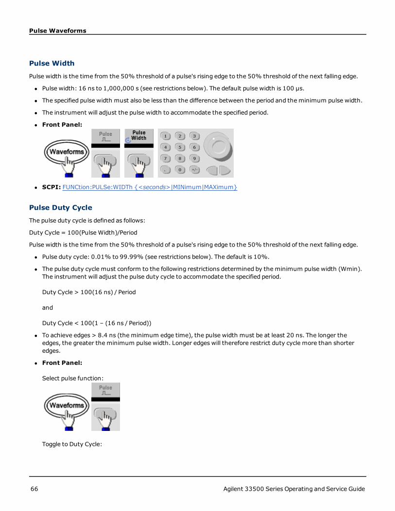
Pulse width is the time from the 50% threshold of a pulse's rising edge to the 50% threshold of the next falling edge.
l Pulse width: 16 ns to 1,000,000 s (see restrictions below). The default pulse width is 100 μs.
l The specified pulse width must also be less than the difference between the period and the minimum pulse width.
l The instrument will adjust the pulse width to accommodate the specified period.
l Front Panel:
l SCPI: FUNCtion:PULSe:WIDTh {<seconds>|MINimum|MAXimum}
Pulse Duty Cycle
The pulse duty cycle is defined as follows:
Duty Cycle = 100(Pulse Width)/Period
Pulse width is the time from the 50% threshold of a pulse's rising edge to the 50% threshold of the next falling edge.
l Pulse duty cycle: 0.01% to 99.99% (see restrictions below). The default is 10%.
l The pulse duty cycle must conform to the following restrictions determined by the minimum pulse width (Wmin).The instrument will adjust the pulse duty cycle to accommodate the specified period.
Duty Cycle > 100(16 ns) / Period
and
Duty Cycle < 100(1 – (16 ns / Period))
l To achieve edges > 8.4 ns (the minimum edge time), the pulse width must be at least 20 ns. The longer theedges, the greater the minimum pulse width. Longer edges will therefore restrict duty cycle more than shorteredges.
l Front Panel:
Select pulse function:
Toggle to Duty Cycle:
66 Agilent 33500 Series Operating and Service Guide

Pulse Waveforms
Enter the Duty Cycle:
l SCPI: FUNCtion:PULSe:DCYCle {<percent>|MIN|MAX}
Edge Times
The edge times set the transition times for the leading and trailing edges of the pulse, either independently or together.The edge time represents the time between the 10% and 90% thresholds.
l Edge time: 8.4 ns to 1 μs (default 10 ns).
l The specified edge timemust fit within the specified pulse width as shown above. The instrument will adjust theedge time to accommodate the specified pulse width.
l Front Panel:
l SCPI:FUNC:PULS:TRAN:LEAD {<seconds>|MIN|MAX}
FUNC:PULS:TRAN:TRA {<seconds>|MIN|MAX}
FUNC:PULS:TRAN[:BOTH] {<seconds>|MIN|MAX}
Agilent 33500 Series Operating and Service Guide 67
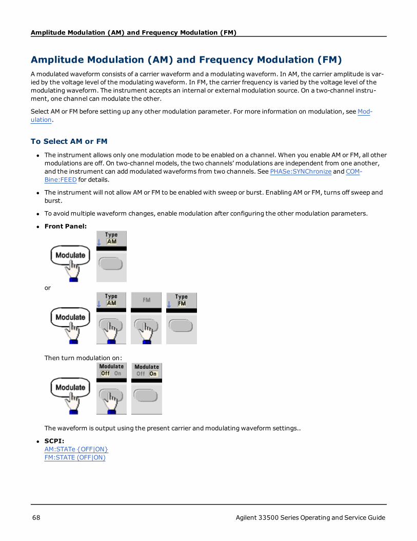
Amplitude Modulation (AM) and Frequency Modulation (FM)
Amplitude Modulation (AM) and Frequency Modulation (FM)Amodulated waveform consists of a carrier waveform and amodulating waveform. In AM, the carrier amplitude is var-ied by the voltage level of the modulating waveform. In FM, the carrier frequency is varied by the voltage level of themodulating waveform. The instrument accepts an internal or external modulation source. On a two-channel instru-ment, one channel can modulate the other.
Select AM or FM before setting up any other modulation parameter. For more information on modulation, see Mod-ulation.
To Select AM or FM
l The instrument allows only one modulation mode to be enabled on a channel. When you enable AM or FM, all othermodulations are off. On two-channel models, the two channels’ modulations are independent from one another,and the instrument can addmodulated waveforms from two channels. See PHASe:SYNChronize and COM-Bine:FEED for details.
l The instrument will not allow AM or FM to be enabled with sweep or burst. Enabling AM or FM, turns off sweep andburst.
l To avoidmultiple waveform changes, enable modulation after configuring the other modulation parameters.
l Front Panel:
or
Then turn modulation on:
The waveform is output using the present carrier andmodulating waveform settings..
l SCPI:AM:STATe {OFF|ON}FM:STATE (OFF|ON)
68 Agilent 33500 Series Operating and Service Guide

Amplitude Modulation (AM) and Frequency Modulation (FM)
Carrier Waveform Shape
l AM or FM carrier shape: Sine (default), Square, Ramp, Pulse, Triangle, Noise, PRBS, or Arbitrary waveform. You can-not use DC as the carrier waveform.
l For FM, the carrier frequency must always be greater than or equal to the frequency deviation. Attempting to set adeviation greater than the carrier frequency will cause the instrument to set the deviation equal to the carrierfrequency.
l The carrier frequency plus the deviation cannot exceed the selected function's maximum frequency plus 100 kHz.If you attempt to set the deviation to an invalid value, the instrument adjusts it to the maximum value allowedwith the present carrier frequency. The remote interface also generates a "Data out of range" error.
l Front Panel:
Then select a waveform shape.
l SCPI:FUNCtion {SINusoid|SQU|PULS|RAMP|TRI|ARB|NOISe|PRBS}
The APPLy command configures a waveform with one command.
Carrier Frequency
The maximum carrier frequency varies by function, as shown below. The default is 1 kHz for all functions. Arbitrarywaveform "frequency" is also set using the FUNCtion:ARBitrary:SRATe command.
Function Minimum Frequency Maximum Frequency
Sine 1 µHz 30 MHz
Square 1 µHz 30 MHz
Ramp 1 µHz 200 kHz
Pulse 1 µHz 30 MHz
PRBS 1 mBPS 50 mPBS
Noise BW 1 mHz 30 MHz
Arbitrary 1 µSa/s 250 MSa/s
l Front Panel:
Agilent 33500 Series Operating and Service Guide 69

Amplitude Modulation (AM) and Frequency Modulation (FM)
l SCPI: [SOURce[1|2]:]FREQuency {<frequency>|MIN|MAX}
The APPLy command configures a waveform with one command.
Modulating Waveform Shape
The instrument accepts an internal or external AM or FMmodulation source. On a two-channel instrument you canmodulate one channel with the other.
You cannot modulate noise with noise, PRBS with PRBS, or an arbitrary waveform with an arbitrarywaveform.
l The modulating waveform shape (internal source)may be:
l Sine wave
l Square with 50% duty cycle
l UpRampwith 100% symmetry
l Triangle with 50% symmetry
l DnRampwith 0% symmetry
l Noise - white gaussian noise
l PRBS - Pseudo Random Bit Sequence (polynomial PN7)
l Arb - Arbitrary waveform
l Front Panel:
or
Then choose the modulating shape:
l SCPI:AM:INTernal:FUNCtion{SIN|SQU|RAMP|NRAM|TRI|NOIS|PRBS|ARB}
70 Agilent 33500 Series Operating and Service Guide

Amplitude Modulation (AM) and Frequency Modulation (FM)
FM:INTernal:FUNCtion {SIN|SQU|RAMP|NRAM|TRI|NOIS|PRBS|ARB}
Modulating Waveform Frequency
The instrument accepts an internal or external modulation source.
l Modulating frequency (internal source): varies by signal type, from 1 µHz to 30 MHz.
l Modulating frequency (external source): 0 to 100 kHz
l Front Panel:
or
Then enter the AM or FM frequency with the knob and keypad:
l SCPI:[SOURce[1|2]:]AM:INTernal:FREQ {<freq>|MIN|MAX}
[SOURce[1|2]:]FM:INTernal:FREQ {<freq>|MIN|MAX}
Modulation Depth (AM)
The modulation depth is a percentage that represents the amplitude variation. At 0% depth, the amplitude is one-halfof the carrier’s amplitude setting. At 100% depth, the amplitude varies according to the modulating waveform, from0% to 100% of the carrier’s amplitude.
l Modulation depth: 0% to 120%. The default is 100%.
l Even at greater than 100% depth, the instrument will not exceed±5 V peak on the output (into a 50 Ω load). Toachieve modulation depth greater than 100%, output carrier amplitude may be reduced.
Agilent 33500 Series Operating and Service Guide 71

Amplitude Modulation (AM) and Frequency Modulation (FM)
l Front Panel:
l SCPI: AM:DEPTh {<depth_in_percent>|MIN|MAX}
Double Sideband Suppressed Carrier AM
The instrument supports two forms of amplitude modulation, "Normal" and Double Sideband Suppressed Carrier(DSSC). In DSSC, the carrier is not present unless the modulating signal has an amplitude greater than zero.
l Front Panel:
l SCPI: [SOURce[1|2]]:AM:DSSC {ON|OFF}.
Frequency Deviation (FM)
The frequency deviation setting represents the peak variation in frequency of the modulated waveform from the carrierfrequency.
When the carrier is PRBS, frequency deviation causes a change in the bit rate equal to one-half of the set frequency.For example, a 10 kHz deviation is equivalent to a 5 KBPS change in bit rate.
l Frequency deviation: 1 µHz to (carrier frequency)/2, default 100 Hz.
l For FM, the carrier frequency must always be greater than or equal to the frequency deviation. Attempting to set adeviation greater than the carrier frequency will cause the instrument to set the deviation equal to the carrierfrequency.
l The carrier frequency plus the deviation cannot exceed the selected function's maximum frequency plus 100 kHz.If you attempt to set the deviation to an invalid value, the instrument adjusts it to the maximum value allowedwith the present carrier frequency. The remote interface also generates a "Data out of range" error.
l Front-Panel
l SCPI: FM:DEViation {<peak_deviation_in_Hz>|MIN|MAX}
72 Agilent 33500 Series Operating and Service Guide
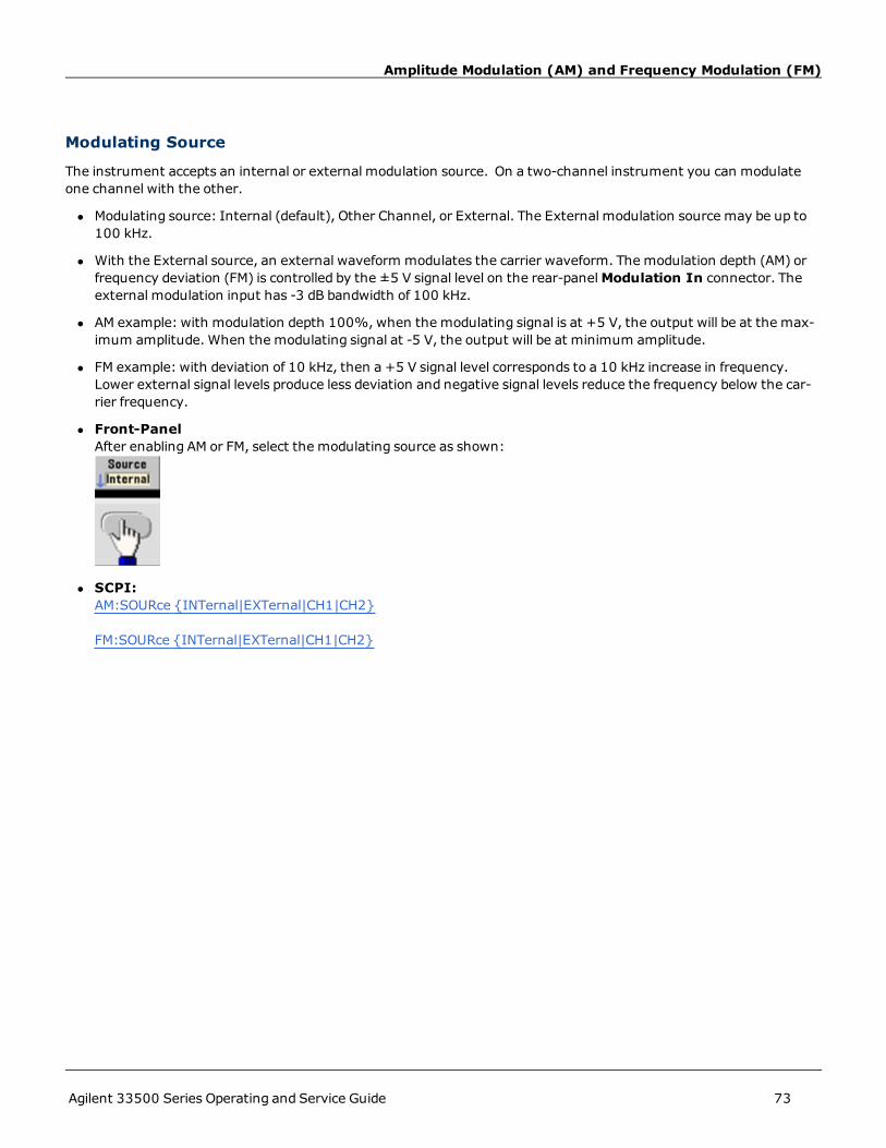
Amplitude Modulation (AM) and Frequency Modulation (FM)
Modulating Source
The instrument accepts an internal or external modulation source. On a two-channel instrument you can modulateone channel with the other.
l Modulating source: Internal (default), Other Channel, or External. The External modulation source may be up to100 kHz.
l With the External source, an external waveform modulates the carrier waveform. The modulation depth (AM) orfrequency deviation (FM) is controlled by the ±5 V signal level on the rear-panelModulation In connector. Theexternal modulation input has -3 dB bandwidth of 100 kHz.
l AM example: with modulation depth 100%, when the modulating signal is at +5 V, the output will be at the max-imum amplitude. When the modulating signal at -5 V, the output will be at minimum amplitude.
l FM example: with deviation of 10 kHz, then a +5 V signal level corresponds to a 10 kHz increase in frequency.Lower external signal levels produce less deviation and negative signal levels reduce the frequency below the car-rier frequency.
l Front-PanelAfter enabling AM or FM, select the modulating source as shown:
l SCPI:AM:SOURce {INTernal|EXTernal|CH1|CH2}
FM:SOURce {INTernal|EXTernal|CH1|CH2}
Agilent 33500 Series Operating and Service Guide 73

Phase Modulation (PM)
Phase Modulation (PM)Amodulated waveform consists of a carrier waveform and amodulating waveform. PM is very similar to FM, but in PMthe phase of the modulated waveform is varied by the instantaneous voltage of the modulating waveform.
For more information on the fundamentals of Phase Modulation, see Tutorial - Modulation.
To Select Phase Modulation
l Only one modulation modemay be enabled at a time. Enabling PM disables the previous modulation mode.
l Enabling PM turns off sweep and burst.
l Front Panel:
The waveform is output using the present carrier andmodulating waveform settings.
l To avoidmultiple waveform changes, enable modulation after configuring the other modulation parameters.
l SCPI:PM:STATe {OFF|ON}
Carrier Waveform Shape
l PM carrier shape: Sine (default), Square, Ramp, Triangle, Pulse, PRBS, or Arbitrary. You cannot use Noise or DC asthe carrier waveform.
l Front Panel:
Then select any waveform except Noise or DC.
l SCPI: FUNCtion {SIN|SQUare|TRIangle|RAMP|PULSe|PRBS|ARB}
l The APPLy command configures a waveform with one command.
l When the carrier is an arbitrary waveform,modulation affects the sample "clock" instead of the full cycle definedby the arbitrary waveform sample set. Because of this, applying pulse modulation to arbitrary waveforms is lim-ited.
Carrier Frequency
The maximum carrier frequency varies by function, as shown below. The default is 1 kHz for all functions. Carrierfrequency must be greater than 20 times the peak modulation frequency.
74 Agilent 33500 Series Operating and Service Guide

Phase Modulation (PM)
Function Minimum Frequency Maximum Frequency
Sine 1 µHz 30 MHz
Square 1 µHz 30 MHz
Ramp/Tri. 1 µHz 200 kHz
Pulse 1 µHz 30 MHz
PRBS 1 mBPS 50 mPBS
Arbitrary 1 µSa/s 250 MSa/s
l Front Panel:
or or any other Frequency key.
After selecting the Frequency key:
l SCPI: [SOURce[1|2]:]FREQuency {<frequency>|MIN|MAX}
l The APPLy command configures a waveform with one command.
Modulating Waveform Shape
The instrument accepts an internal or external modulation source.
l The modulating waveform shape (internal source)may be:
l Sine wave
l Square with 50% duty cycle
l UpRampwith 100% symmetry
l Triangle with 50% symmetry
l DnRampwith 0% symmetry
l Noise - white gaussian noise
l PRBS - Pseudo Random Bit Sequence (polynomial PN7)
l Arbitrary waveform
Agilent 33500 Series Operating and Service Guide 75

Phase Modulation (PM)
l You can use noise as the modulating waveshape, but you cannot use noise or DC as the carrier waveform.
l Front-Panel:
l SCPI: PM:INTernal:FUNCtion {SIN|SQU|RAMP|NRAMp| TRI|NOIS|PRBS|ARB}
Modulating Waveform Frequency
The instrument accepts an internal or external modulation source. The external modulation input has a -3dB band-width of 100 kHz.
l Modulating frequency (internal): 1 µHz to 30 MHz, default 10 Hz.
l Front Panel:
Then set the modulating waveform frequency:
l SCPI: [SOURce[1|2]:]PM:INT:FREQ {<freq>|MIN|MAX}
Phase Deviation
The phase deviation setting represents the peak variation in phase of the modulated waveform from the carrier wave-form. The phase deviation can be set from 0 to 360 degrees (default 180).
l Front Panel:
Then set the phase deviation:
76 Agilent 33500 Series Operating and Service Guide

Phase Modulation (PM)
l SCPI: PM:DEViation {<deviation_in_degrees>|MIN|MAX}
When the carrier is an arbitrary waveform, the deviation applies to the sample clock. Therefore, the effect on the fullarbitrary waveform is much less than that seen with standard waveforms. The extent of the reduction depends on thenumber of points in the arbitrary waveform.
Modulating Source
The instrument accepts an internal or external modulation source.
l Modulating source: Internal (default), Other Channel, or External. The External modulation source may be up to100 kHz.
l With the External source, the carrier waveform is modulated with an external waveform. The ±5 V signal levelpresent on the rear-panelModulation In connector controls the phase deviation. For example, if the deviation isset to 180 degrees, a +5 V signal corresponds to a 180 degree phase shift. Lower levels produce less deviation.
l Front Panel:
l SCPI:PM:SOURce {INTernal|EXTernal}
Agilent 33500 Series Operating and Service Guide 77

Frequency-Shift Keying (FSK) Modulation
Frequency-Shift Keying (FSK) ModulationYou can configure the instrument to "shift" its output frequency between two preset values using FSKmodulation. Therate at which the output shifts between the two frequencies (called the "carrier frequency" and the "hop frequency") isdetermined by the internal rate generator or the signal level on the rear-panel Ext Trig connector.
See Front Panel Menu Operation - Output an FSKWaveform for details on FSK using the front panel.
To Select FSK Modulation
FSKey:STATe {OFF|ON}
l Only one modulation modemay be enabled at a time. Enabling FSK turns off the previous modulation mode.
l You cannot enable FSK when sweep or burst is enabled. Enabling FSK turns off sweep and burst.
l To avoidmultiple waveform changes, enable modulation after configuring the other modulation parameters.
FSK Carrier Frequency
[SOURce[1|2]:]FREQuency {<frequency>|MIN|MAX}
The maximum carrier frequency varies by function, as shown below. The default is 1 kHz for all functions.
Function Minimum Carrier Frequency Maximum Carrier Frequency
Sine 1 µHz 30 MHz
Square 1 µHz 30 MHz
Ramp/Tri. 1 µHz 200 kHz
Pulse 1 µHz 30 MHz
l When the External source is selected, the output frequency is determined by the signal level on the rear-panel ExtTrig connector. When a logic low is present, the carrier frequency is output. With a logic high, the hop frequency isoutput.
FSK "Hop" Frequency
[SOURce[1|2]:]FSKey:FREQuency {<freq>|MIN|MAX}
The maximum alternate ("hop") frequency depends on the function. The default is 100 Hz for all functions. The inter-nal modulating waveform is a 50% duty cycle square wave.
Function Minimum Hop Frequency Maximum Hop Frequency
Sine 1 µHz 30 MHz
Square 1 µHz 30 MHz
Ramp/Tri. 1 µHz 200 kHz
Pulse 1 µHz 30 MHz
78 Agilent 33500 Series Operating and Service Guide

Frequency-Shift Keying (FSK) Modulation
l When the External source is selected, the output frequency is determined by the signal level on the rear-panel ExtTrig connector. When a logic low is present, the carrier frequency is output. With a logic high, the hop frequency isoutput.
FSK Rate
FSKey:INTernal:RATE {<rate_in_Hz>|MIN|MAX}
The FSK rate is the rate at which the output frequency "shifts" between the carrier frequency and the hop frequencyusing the internal FSK source.
l FSK rate (internal source): 125 µHz to 1 MHz, default 10 Hz.
l The FSK rate is ignoredwhen the external FSK source is selected.
FSK Source
FSKey:SOURce {INTernal|EXTernal}
May be Internal (default) or External.
l When the Internal source is selected, the rate at which the output frequency "shifts" between the carrierfrequency and hop frequency is determined by the FSK rate.
l When the External source is selected, the output frequency is determined by the signal level on the rear-panel ExtTrig connector. When a logic low is present, the carrier frequency is output. With a logic high, the hop frequency isoutput.
l The connector used for externally-controlled FSK waveforms (Ext Trig) is not the same connector that is used forexternally-modulated AM, FM, PM, and PWMwaveforms (Modulation In). When used for FSK, the Ext Trig con-nector does not have adjustable edge polarity.
Agilent 33500 Series Operating and Service Guide 79

Pulse Width Modulation (PWM)
Pulse Width Modulation (PWM)This section discusses PWM, which stands for pulse-width modulation. PWM is only available for the Pulse waveform,and the pulse width varies according to the modulating signal. The amount by which the pulse width varies is called thewidth deviation, and it can be specified as a percentage of the waveform period (that is, duty cycle) or in units of time.For example, if you specify a pulse with 20% duty cycle and then enable PWMwith a 5% deviation, the duty cyclevaries from 15% to 25% under control of the modulating signal.
The instrument accepts an internal or external modulation source.
To Select PWM
l You cannot enable PWMwhen sweep or burst is enabled.
l To avoidmultiple waveform changes, enable modulation after configuring the other modulation parameters.
l Front Panel:
The waveform is output using the present carrier andmodulating waveform settings.
l SCPI: PWM:STATe {OFF|ON}
Modulating Waveform Shape
The instrument accepts an internal or external modulation source.
l The modulating waveform shape (internal source)may be:
l Sine wave
l Square with 50% duty cycle
l UpRampwith 100% symmetry
80 Agilent 33500 Series Operating and Service Guide

Pulse Width Modulation (PWM)
l Triangle with 50% symmetry
l DnRampwith 0% symmetry
l Noise - white gaussian noise
l PRBS - Pseudo Random Bit Sequence (polynomial PN7)
l Arbitrary waveform
l You can use noise as the modulating waveshape, but you cannot use noise, arbitrary waveforms, or DC as the car-rier.
l Front-Panel:
l SCPI: PWM:INTernal:FUNCtion {SIN|SQUare|RAMP|NRAMp| TRIangle|NOISe|PRBS|ARB}
Modulating Waveform Frequency
The instrument accepts an internal or external modulation source. The external modulation input has a -3dB band-width of 100 kHz.
l Modulating frequency (internal source): 1 µHz to 30 MHz. The default is 10 Hz.
l Front Panel:
l SCPI:[SOURce[1|2]:]PWM:INT:FREQ {<freq>|MIN|MAX}
Agilent 33500 Series Operating and Service Guide 81

Pulse Width Modulation (PWM)
Width or Duty Cycle Deviation
The PWM deviation setting is the peak variation in width of the modulated pulse waveform. You can set it in units oftime or duty cycle.
l Front-Panel:
To set deviation in terms of duty cycle:
l SCPI: PWM:DEViation {<width or duty_cycle>|MIN|MAX}
l The sum of the pulse width and deviation must satisfy the formula:
Pulse Width + Deviation < Period – 16 ns
l If necessary, the instrument will adjust the deviation to accommodate the specified period.
Modulating Source
The instrument accepts an internal or external modulation source.
l Modulating source: Internal (default), Other Channel, or External. The External modulation source may be up to100 kHz.
l If you select the Externalmodulating source, the deviation is controlled by the ±5 V signal level on the rear-panelModulation In connector. For example, if you have set the deviation to 1 µs, then a +5 V signal corresponds to a1 µs increase in width. Lower signal levels produce less deviation.
82 Agilent 33500 Series Operating and Service Guide

Pulse Width Modulation (PWM)
l Front Panel:
l SCPI: PWM:SOURce {INTernal|EXTernal}
Pulse Waveform
l Pulse is the only waveform shape supported for PWM.
l Front Panel:
l SCPI: FUNCtion PULSe
The APPLy command configures a waveform with one command.
Pulse Period
The range for the pulse period is from the reciprocal of the instrument's maximum frequency up to 1,000,000 s(default 100 µs).
l Front-Panel:
l SCPI: FUNCtion:PULSe:PERiod {<seconds>|MIN|MAX}
Note that the waveform period limits the maximum deviation.
Agilent 33500 Series Operating and Service Guide 83

Sum Modulation
Sum ModulationSum modulation adds a modulating signal to any carrier waveform; it is typically used to add gaussian noise to a carrier.The modulating signal is added to the carrier as a percentage of carrier waveform amplitude.
Enable Sum
l To avoidmultiple waveform changes, enable Sum after configuring other modulation parameters.
l Front Panel:
l SCPI: SUM:STATe {OFF|ON}
Modulating Waveform Shape
The instrument accepts an internal or external modulation source. On a two-channel instrument you can modulateone channel with the other.
l The modulating waveform shape (internal source)may be:
l Sine wave
l Square with 50% duty cycle
l UpRampwith 100% symmetry
l Triangle with 50% symmetry
l DnRampwith 0% symmetry
l Noise
l PRBS with PN7 sequence
l Arbitrary waveform
84 Agilent 33500 Series Operating and Service Guide

Sum Modulation
l Front Panel:
l SCPI: SUM:INTernal:FUNCtion {SIN|SQU|RAMP|NRAM|TRI|NOIS|PRBS|ARB)
Modulating Waveform Frequency
The instrument accepts an internal or external modulation source. On a two-channel instrument you can modulateone channel with the other.
l Modulating frequency (internal source): 1 µHz to 30 MHz, default 100 Hz.
l Front Panel:
l SCPI: [SOURce[1|2]:]SUM:INTernal:FREQuency {<frequency>|MIN|MAX}
Sum Amplitude
The Sum Amplitude represents the amplitude of the signal added to the carrier (in percent of carrier amplitude).
l Amplitude setting: 0 to 100% of carrier amplitude, 0.01% resolution.
l Sum Amplitude remains a constant fraction of carrier amplitude and tracks carrier amplitude changes.
l Front Panel:
l SCPI: SUM:AMPLitude {<amplitude>|MIN|MAX}
Agilent 33500 Series Operating and Service Guide 85

Sum Modulation
Modulating Source
The instrument accepts an internal or external modulation source. On a two-channel instrument you can modulateone channel with the other.
l Modulating source: Internal (default), Other Channel, or External. The External modulation source may be up to100 kHz.
l With the external source, the carrier waveform is summed by the ±5 V signal level on the rear-panelModulationIn connector. For example, if you have set the sum amplitude to 10%, then when the modulating signal is at +5V, the output will be at the maximum amplitude (110% of carrier amplitude). When the modulating signal is at -5V, the output will be at the minimum amplitude (90% of carrier amplitude).
l Front Panel:
l SCPI: SUM:SOURce {INTernal|EXTernal|CH1|CH2}
86 Agilent 33500 Series Operating and Service Guide

Frequency Sweep
Frequency SweepIn frequency sweepmode, the instrument moves from the start frequency to the stop frequency at a specified sweeprate. You can sweep up or down in frequency, with either linear or logarithmic spacing. You can also configure theinstrument to output one sweep from start frequency to stop frequency by applying an external or manual trigger. Theinstrument can sweep sine, square, pulse, ramp, triangle, or arbitrary waveforms (PRBS, noise and DC are notallowed).
You can specify a hold time, during which the sweep remains at the stop frequency, and a return time, during whichthe frequency changes linearly from the stop frequency to the start frequency.
For more information, see Frequency Sweep.
To Select Sweep
The instrument will not allow sweep or list mode to be enabled at the same time that burst or any modulation mode isenabled. When you enable sweep, the burst or modulation mode is turned off.
l To avoidmultiple waveform changes, enable the sweepmode after configuring the other parameters.
l Front Panel:
Output a sweep using the present amplitude, offset, and frequency:
l SCPI:FREQuency:MODE SWEEP
SWEep:STATe {OFF|ON}
Start Frequency and Stop Frequency
The start frequency and stop frequency set the sweep’s upper and lower frequency bounds. The sweep begins at thestart frequency, sweeps to the stop frequency, and then resets back to the start frequency.
l Start and Stop frequencies: 1 µHz to 30 MHz (limited to 200 kHz for ramps). The sweep is phase continuous overthe full frequency range. The default start frequency is 100 Hz. The default stop frequency is 1 kHz.
l To sweep up in frequency, set the start frequency less than the stop frequency. To sweep down in frequency, setthe opposite relationship.
l Sync setting Normal:Sync pulse is high throughout the sweep.
l Sync setting Carrier:Sync pulse has a 50% duty cycle for every waveform cycle.
l Sync setting Marker:Sync pulse goes high at the beginning and goes low at the marker frequency.
Agilent 33500 Series Operating and Service Guide 87

Frequency Sweep
l Front Panel:
l SCPI:[SOURce[1|2]:]FREQuency:STARt {<freq>|MIN|MAX}
[SOURce[1|2]:]FREQuency:STOP {<freq>|MIN|MAX}
Center Frequency and Frequency Span
You can also set the sweep frequency boundaries of the sweep using a center frequency and frequency span. Theseparameters are similar to the start frequency and stop frequency (above) and they provide added flexibility.
l Center frequency: 1 µHz to 30 MHz (limited to 200 kHz for ramps). The default is 550 Hz.
l Frequency span: -30 µHz to 30 MHz (limited to 200 kHz for ramps). The default is 900 Hz.
l To sweep up in frequency, set a positive frequency span; to sweep down, set a negative frequency span.
l For sweeps with Marker Off, the Sync signal is a square waveform with a 50% duty cycle. (missing or bad snippet)The frequency of the Syncwaveform is equal to the specified sweep time. The signal is output from the front-panel Sync connector.
l For frequency sweeps with Marker On, the Sync signal is a TTL "high" at the beginning of the sweep and a "low" atthe marker frequency. You can change this with OUTPut[1|2]:SYNC:MODE MARKER.
l Front Panel:
88 Agilent 33500 Series Operating and Service Guide

Frequency Sweep
l SCPI:[SOURce[1|2]:]FREQuency:CENTer {<freq>|MIN|MAX}
[SOURce[1|2]:]FREQuency:SPAN {<freq>|MIN|MAX}
Sweep Mode
You can sweepwith linear or logarithmic spacing, or with a list of sweep frequencies. For a linear sweep, the instrumentvaries the output frequency linearly during the sweep. A logarithmic sweep, varies the output frequency log-arithmically.
The selectedmode does not affect the sweep return (from stop to start, if one is set). The sweep return is always linear.
l Front-Panel:
l SCPI: [SOURce[1|2]:]SWEep:SPACing {LINear|LOGarithmic}
Sweep Time
Sweep time specifies the number of seconds required to sweep from the start frequency to the stop frequency. Theinstrument calculates the number of points in the sweep based on the sweep time.
l Sweep time: 1 ms to 250,000 seconds, default 1 s. For a linear sweep in immediate trigger mode, the maximumtotal sweep time (including hold time and return time) is 8,000 s. The maximum total sweep time for linearsweeps using other trigger modes is 250,000 s, and the maximum total sweep time for logarithmic sweeps is 500s.
Agilent 33500 Series Operating and Service Guide 89

Frequency Sweep
l Front-Panel:
l SCPI: [SOURce[1|2]:]SWEep:TIME {<seconds>|MIN|MAX}
Hold Time
Hold time specifies time (in seconds) to remain at the stop frequency, and return time specifies the number of secondsto return from the stop frequency to the start frequency.
l Hold time and return time: 0 to 3600 seconds (default 0).
l Front-Panel:
l SCPI:SWEep:HTIMe {<seconds>|MINimum|MAXimum}
SWEep:RTIMe {<seconds>|MINimum|MAXimum}
90 Agilent 33500 Series Operating and Service Guide

Frequency Sweep
Marker Frequency
If desired, you can set the frequency at which the signal on the front-panel Sync connector goes to a logic low duringthe sweep. The Sync signal always goes from low to high at the beginning of the sweep.
l Marker frequency: 1 µHz to 30 MHz (limited to 200 kHz for ramp). The default is 500 Hz.
l When the sweepmode is enabled, the marker frequency must be between the specified start frequency and stopfrequency. If you attempt to set the marker frequency to a frequency not in this range, the instrument will set themarker frequency equal to the start frequency or stop frequency (whichever is closer).
l The Sync enable setting is overridden by enabling the marker usedwith the sweepmode. Therefore, when themarker is enabled (with sweepmode also enabled), the Sync setting is ignored.
l You cannot configure the marker frequency with the front panel menus unless the Sync source is the sweepingchannel.
l Front Panel:
l SCPI: [SOURce[1|2]:]MARKer:FREQuency {<freq>|MIN|MAX}
Sweep Trigger Source
In sweepmode, the instrument outputs a single sweepwhen a trigger signal is received. After one sweep from thestart frequency to the stop frequency, the instrument waits for the next trigger while outputting the start frequency.
l Sweep trigger source: Internal (default), External, Time, or Manual.
l With the Internal (immediate) source, the instrument outputs a continuous sweep at a rate determined by thetotal of the hold time, sweep time and return time. The sweep time for this source is limited to 8000 seconds.
l With the External source, the instrument accepts a hardware trigger on the rear-panel Ext Trig connector and ini-tiates one sweep each time Ext Trig receives a TTL pulse with the specified polarity.
l The trigger periodmust be greater than or equal to the specified sweep time.
l With the Manual source, the instrument outputs one sweep each time the front-panel [Trigger] key is pressed.
Agilent 33500 Series Operating and Service Guide 91

Frequency Sweep
l Front-Panel:
l To specify the slope of the trigger signal edge:
l SCPI:TRIGger[1|2]:SOURce {IMM|EXT|TIMer|BUS}
TRIGger[1|2]:SLOPe {POSitive|NEGative}
See Triggering for more information.
Trigger Out Signal
A "trigger out" signal is provided on the rear-panel Ext Trig connector (usedwith burst and sweep only). When ena-bled, a TTL-compatible pulse with either a rising edge (default) or falling edge is output from this connector at the begin-ning of the sweep or burst.
l When the Internal (immediate) trigger source is selected, the instrument outputs a square waveform with a 50%duty cycle from the Ext Trig connector at the beginning of the sweep or burst. The frequency of the waveform cor-responds to the specified burst period or total sweep time.
l When the External trigger source is selected, the instrument disables the "trigger out" signal. The Ext Trig con-nector cannot be used for sweep or burst and trigger out at the same time (an externally-triggeredwaveform usesthe same connector to trigger the sweep or burst).
l When Manual trigger source is selected, the instrument outputs a pulse (>1 μs pulse width) from the Ext Trig con-nector at the beginning of each sweep or burst.
l To specify whether the instrument triggers on the rising or falling edge of the Ext Trig connector, press [Trigger]> Trig Out Setup. Then select the desired edge by pressing Trig Out.
l SCPI:OUTPut:TRIGger:SLOPe {POSitive|NEGative}
OUTPut:TRIGger {OFF|ON}
Frequency List
In frequency list mode, the instrument "steps" through a list of frequencies, dwelling on each frequency for a specifiedperiod. You may also control progress through the list with triggering.
92 Agilent 33500 Series Operating and Service Guide

Frequency Sweep
l The instrument will not allow sweep or list mode to be enabled at the same time that burst or any modulationmode is enabled. When you enable sweep, the burst or modulation mode is turned off.
l To avoidmultiple waveform changes, enable list mode after configuring its parameters.
l Front Panel: Enable list before setting any other list parameter. Press [Sweep] > Type > List.
l SCPI:FREQuency:MODE LIST
LIST:FREQuency <number>, <number>, …
Progress through list is controlled by the trigger system. If trigger source is internal or immediate, the dwell time set-ting (LIST:DWELl) determines time spent at each frequency. For any other trigger source, dwell time is determined bytrigger event spacing.
Agilent 33500 Series Operating and Service Guide 93

Burst Mode
Burst ModeThe instrument can output a waveform for a specified number of cycles, called a burst. Burst is allowedwith sine,square, triangle, ramp, pulse, PRBS, or arbitrary waveforms (noise allowed only in gated burst mode; DC is notallowed).
For details, see Tutorial - Burst.
To Select Burst
Burst cannot be enabled when sweep or modulation is enabled. Enabling burst turns off sweep andmodulation.
l To avoidmultiple waveform changes, enable burst mode after configuring other parameters.
l Front-Panel:
l SCPI: [SOURce[1|2]:]BURSt:STATe {OFF|ON}
Burst Mode
Burst has twomodes, described below. Selectedmode controls allowable trigger source, andwhich other burst param-eters apply.
l Triggered Burst Mode (default): The instrument outputs a waveform for specified number of cycles (burstcount) each time trigger is received. After outputting specified number of cycles, instrument stops andwaits fornext trigger. The instrument can use an internal trigger to initiate burst, or you can provide external trigger bypressing the front-panel [Trigger] key, applying trigger signal to rear-panel Ext Trig connector, or sending soft-ware trigger command from remote interface.
l External Gated Burst Mode: Output waveform is on or off, based on level of external signal applied to rear-panelExt Trig connector. When the gate signal is true, the instrument outputs a continuous waveform.When the gatesignal goes false, the current waveform cycle is completed and the instrument stops while remaining at the volt-age level corresponding to the starting burst phase of the selected waveform. The noise waveform output stopsimmediately when the gate signal goes false.
Parameter Burst Mode(BURS:MODE)
Burst Count(BURS:NCYC)
Burst Period(BURS:INT:PER)
Burst Phase(BURS:PHAS)
TriggerSource
(TRIG:SOUR)
Triggered BurstMode:
Internal Trigger
TRIGgered Available Available Available IMMediate
Triggered BurstMode:
External Trigger
TRIGgered Available Not Used Available EXTernal, BUS
94 Agilent 33500 Series Operating and Service Guide

Burst Mode
Parameter Burst Mode(BURS:MODE)
Burst Count(BURS:NCYC)
Burst Period(BURS:INT:PER)
Burst Phase(BURS:PHAS)
TriggerSource
(TRIG:SOUR)
Gated Burst Mode:
External Trigger
GATed Not Used Not Used Available Not Used
Timer Burst Mode:
Internal Trigger
TRIGgered Available Not Used Available TIMer
.
l In gatedmode, burst count, burst period, and trigger source are ignored (used for triggered burst only). Manualtriggers ignored; no error generated.
l In gatedmode, you can specify polarity of signal on rear-panel Ext Trig connector ([SOURce[1|2]:]BURSt:GATE:-POLarity {NORMal|INVerted}). Default is NORMal (true-high).
l Front Panel:
l SCPI: [SOURce[1|2]:]BURSt:MODE {TRIGgered|GATed}
Waveform Frequency
You can specify the signal frequency during the burst in triggered and external gatedmodes. In the triggeredmode, thenumber of cycles specified by the burst count is output at the waveform frequency. In the external gatedmode, thewaveform frequency is output when the external gate signal is true.
This differs from the "burst period," which specifies interval between bursts (triggeredmode only).
l Waveform frequency: 1 µHz to 30 MHz (limited to 200 kHz for ramps). The default value is 1 kHz. (For an inter-nally triggered burst waveform, the minimum frequency is 126 µHz.)
l Front Panel:
l SCPI: [SOURce[1|2]:]FREQuency {<frequency>|MIN|MAX}
The APPLy command configures a waveform with one command.
Agilent 33500 Series Operating and Service Guide 95

Burst Mode
Burst Count
Number of cycles (1 to 100,000,000 or infinite) to be output per burst. Used in the triggered burst mode only (internalor external source).
l With Internal trigger source, specified number of cycles are output continuously at a rate determined by burstperiod. The burst period is the time between the starts of consecutive bursts. Also, the burst count must be lessthan the product of burst period andwaveform frequency:
Burst Period > (Burst Count)/(Waveform Frequency) + 1µsec
l The instrument will increase burst period to its maximum value to accommodate specified burst count (but wave-form frequency will not be changed).
l In gated burst mode, burst count is ignored. However, if you change the burst count from the remote interfacewhile in the gatedmode, the instrument remembers the new count andwill use it when the triggeredmode isselected.
l Front Panel:
or
l SCPI: [SOURce[1|2]:]BURS:NCYC {<#_cycles>|INF|MIN|MAX}
Burst Period
Burst period is the time from the start of one burst to the start of next burst (1 µs to 8000 s, default 10 ms). Used ininternal triggered burst mode only. Burst period differs from "waveform frequency," which specifies the frequency ofthe bursted signal.
l Burst period is used only when Immediate triggering is enabled. The burst period is ignoredwhen manual or exter-nal triggering is enabled (or when the gated burst mode is selected).
l You cannot specify a burst period that is too short for the instrument to output with the specified burst count andfrequency. If the burst period is too short, the instrument will increase it as needed to continuously re-trigger theburst.
96 Agilent 33500 Series Operating and Service Guide

Burst Mode
l Front Panel:
l SCPI: [SOUR[1|2]:]BURS:INT:PERiod {<seconds>|MIN|MAX}
Start Phase
Start phase of the burst, from -360 to +360 degrees (default 0).
l Specify the start phase units with UNIT:ANGLe.
l Always displayed in degrees on front panel (never radians). If set in radians from remote interface, instrument con-verts value to degrees on front panel.
l For sine, square, and ramp, 0 degrees is the point at which the waveform crosses 0 V (or DC offset) in a positive-going direction. For arbitrary waveforms, 0 degrees is the first waveform point. Start phase has no effect on noise.
l Start phase also used in gated burst mode.When the gate signal goes false, the current waveform cycle finishes,and output remains at the voltage level of the starting burst phase.
l Front Panel:
l SCPI: [SOURce[1|2]:]BURSt:PHASe {<angle>|MIN|MAX}
Burst Trigger Source
In triggered burst mode:
l The instrument outputs a waveform of the specified number of cycles (burst count) when a trigger received. Afterthe specified number of cycles have been output, the instrument stops andwaits for next trigger.
l IMMediate (internal): the instrument outputs continuously when burst mode is enabled. The rate at which theburst is generated is determined by BURSt:INTernal:PERiod.
l EXTernal: the instrument accepts a hardware trigger at the rear-panel Ext Trig connector. The instrument out-puts one burst of the specified number of cycles each time Ext Trig receives a TTL pulse with the proper polarity(TRIGger[1|2]:SLOPe). External trigger signals during a burst are ignored.
l BUS (software): the instrument initiates one burst each time a bus trigger (*TRG) is received. The front-panel[Trigger] key is illuminated when the instrument is waiting for a bus trigger.
l EXTernal or BUS: burst count and burst phase remain in effect, but burst period is ignored.
l TIMer: trigger events are spaced by a timer, with the first trigger as soon as INIT occurs.
Agilent 33500 Series Operating and Service Guide 97

Burst Mode
l Front Panel:
l
l To specify whether the instrument triggers on a rising or falling edge of the signal at the Ext Trig connector, selectthe external trigger source before choosing Trigger Setup.
l SCPI:TRIGger[1|2]:SOURce {IMM|EXT|TIMer|BUS}
TRIGger[1|2]:SLOPe {POSitive|NEGative}
See Triggering for more information.
Trigger Out Signal
A "trigger out" signal is provided on the rear-panel Ext Trig connector (usedwith burst and sweep only). When ena-bled, a TTL-compatible pulse with either a rising edge (default) or falling edge is output from this connector at the begin-ning of the sweep or burst.
l When the Internal (immediate) trigger source is selected, the instrument outputs a square waveform with a 50%duty cycle from the Ext Trig connector at the beginning of the sweep or burst. The frequency of the waveform cor-responds to the specified burst period or total sweep time.
l When the External trigger source is selected, the instrument disables the "trigger out" signal. The Ext Trig con-nector cannot be used for sweep or burst and trigger out at the same time (an externally-triggeredwaveform usesthe same connector to trigger the sweep or burst).
l When Manual trigger source is selected, the instrument outputs a pulse (>1 μs pulse width) from the Ext Trig con-nector at the beginning of each sweep or burst.
l Front-Panel
alt="Burst Off softkey"
98 Agilent 33500 Series Operating and Service Guide
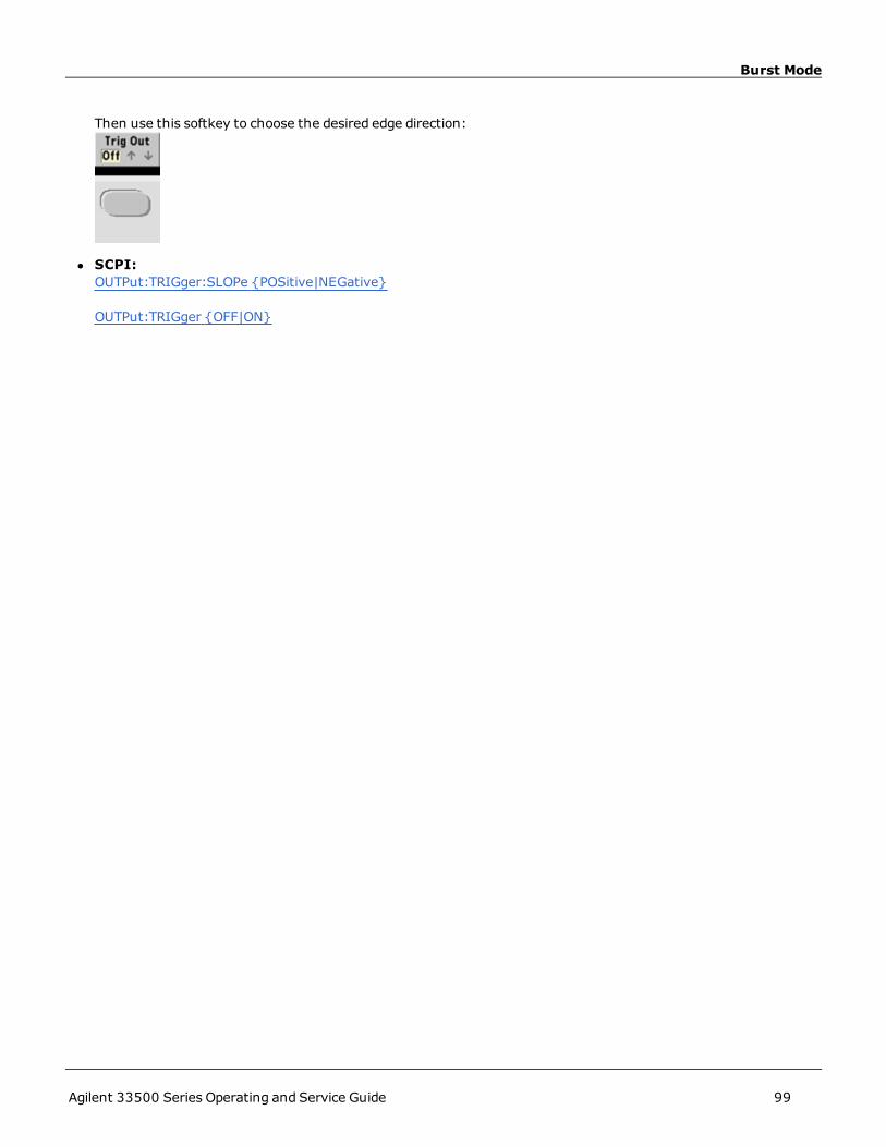
Burst Mode
Then use this softkey to choose the desired edge direction:
l SCPI:OUTPut:TRIGger:SLOPe {POSitive|NEGative}
OUTPut:TRIGger {OFF|ON}
Agilent 33500 Series Operating and Service Guide 99

Triggering
TriggeringThis section describes the instrument's triggering system.
Trigger Overview
This triggering information applies to sweep and burst only. You can issue triggers for sweeps or bursts using internaltriggering, external triggering, timer triggering, or manual triggering.
l Internal or "automatic" (default): instrument outputs continuously when sweep or burst mode is selected.
l External: uses rear-panel Ext Trig connector to control sweep or burst. The instrument initiates one sweep or out-puts one burst each time Ext Trig receives a TTL pulse. You can select whether instrument triggers on rising or fall-ing edge.
l Manual: triggering initiates one sweep or outputs one burst each time you press [Trigger] on the front panel.
l When you sweep a list, trigger moves the waveform to the next frequency in the list.
l The [Trigger] key is disabled when in remote andwhen a function other than burst or sweep is currentlyselected.
Trigger Sources
This triggering information applies to sweep and burst only. You must specify the source from which the instrumentaccepts a trigger.
l Sweep and Burst trigger source: Immediate (default), External, Manual or Timer.
l The instrument will accept a manual trigger, a hardware trigger from the rear-panel Ext Trig connector, or con-tinuously output sweeps or bursts using an internal trigger. You can also trigger bursts based on a timer. At power-on, immediate trigger is selected.
l Trigger source setting is volatile; set to internal trigger (front panel) or immediate (remote interface) by powercycle or *RST.
l Front Panel:Enable sweep or burst. Then:
l SCPI: TRIG[1|2]:SOUR {IMMediate|EXTernal|TIMer|BUS}
The APPLy command automatically sets the source to Immediate.
Immediate Triggering
Internal trigger mode (default): instrument continuously outputs sweep or burst (as specified by sweep time or burstperiod).
100 Agilent 33500 Series Operating and Service Guide

Triggering
Front-Panel:
SCPI: TRIGger:SOURce IMMediate
Manual Triggering
Manual trigger mode (front panel only): you manually trigger the instrument by pressing [Trigger]. The instrumentinitiates one sweep or burst for each time you press [Trigger]. The button is lit when you are in the trigger menu andthe instrument is waiting for a manual trigger. The button blinks when the instrument is waiting for a manual trigger,but you are not in the trigger menu. The key is disabled when the instrument is in remote.
External Triggering
In external trigger mode, the instrument accepts a hardware trigger at the rear-panel Ext Trig connector. The instru-ment initiates one sweep or burst each time Ext Trig receives a TTL pulse with the specified edge. The external triggermode is like the manual trigger mode except that you apply the trigger to the Ext Trig connector.
See Trigger Input Signal, below.
Front-Panel:
To specify whether the instrument triggers on a rising or falling edge, press Trigger Setup and select the edge direc-tion by pressingSlope.
SCPI:TRIGger:SOURce EXTernal
TRIGger:SLOPe {POSitive|NEGative}
Software (Bus) Triggering
Available only from remote interface, this is similar to manual trigger mode from the front panel, but you trigger theinstrument with a bus trigger command. The instrument initiates one sweep or outputs one burst each time a bustrigger command is received. The key blinks when a bus trigger command is received.
To select the bus trigger source, send TRIGger:SOURce BUS.
To trigger instrument from remote interface (GPIB, USB, or LAN) when Bus source is selected, send TRIG or *TRG(trigger). The front-panel [Trigger] key is illuminated when the instrument is waiting for a bus trigger.
Timer Triggering
The timer trigger mode issues triggers a fixed period apart. To select the bus trigger source, send TRIGger:SOURce TIM.
Agilent 33500 Series Operating and Service Guide 101

Triggering
Trigger Input Signal
This rear-panel connector is used in the followingmodes:
l Triggered SweepMode: Press Trigger Setup > Source Ext, or execute TRIG:SOUR EXT (sweepmust be ena-bled). When TTL edge of correct polarity is received on the Ext Trig connector, instrument outputs a single sweep.
l Externally-Modulated FSKMode: Press Source or execute FSK:SOUR EXT (FSKmust be enabled). When a logiclow level is present, carrier frequency is output. When a logic high level is present, hop frequency is output. Max-imum external FSK rate is 100 kHz.
l Triggered Burst Mode: Press Trigger Setup > Source Ext, or execute TRIG:SOUR EXT (burst must be enabled).The instrument outputs a waveform with specified number of cycles (burst count) each time a trigger is receivedfrom the specified trigger source.
l External Gated Burst Mode: PressGated softkey or execute BURS:MODE GATwith burst enabled. When externalgate signal is true, instrument outputs a continuous waveform.When external gate signal goes false, the currentwaveform cycle completes and then instrument stops while remaining at voltage level corresponding to startingburst phase. For noise, output stops as soon as the gate signal goes false.
Trigger Output Signal
l A "trigger out" signal is provided on the rear-panel Ext Trig connector (usedwith burst and sweep only). Whenenabled, a TTL-compatible pulse with either a rising edge (default) or falling edge is output from this connector atthe beginning of the sweep or burst.
l
l Internal (immediate) or Timer trigger source: instrument outputs a square wave with a 50% duty cycle from theExt Trig connector at the beginning of the sweep or burst. Waveform period equals specified sweep time or burstperiod.
l External trigger source: instrument disables "trigger out" signal. The rear-panel Ext Trig connector cannot beused for both operations simultaneously (an externally-triggeredwaveform uses the same connector to triggersweep or burst).
l Bus (software) or manual trigger source: instrument outputs a pulse (>1 μs pulse width) from Ext Trig connectorat beginning of each sweep or burst.
l Front Panel: Enable sweep or burst. Then:
102 Agilent 33500 Series Operating and Service Guide
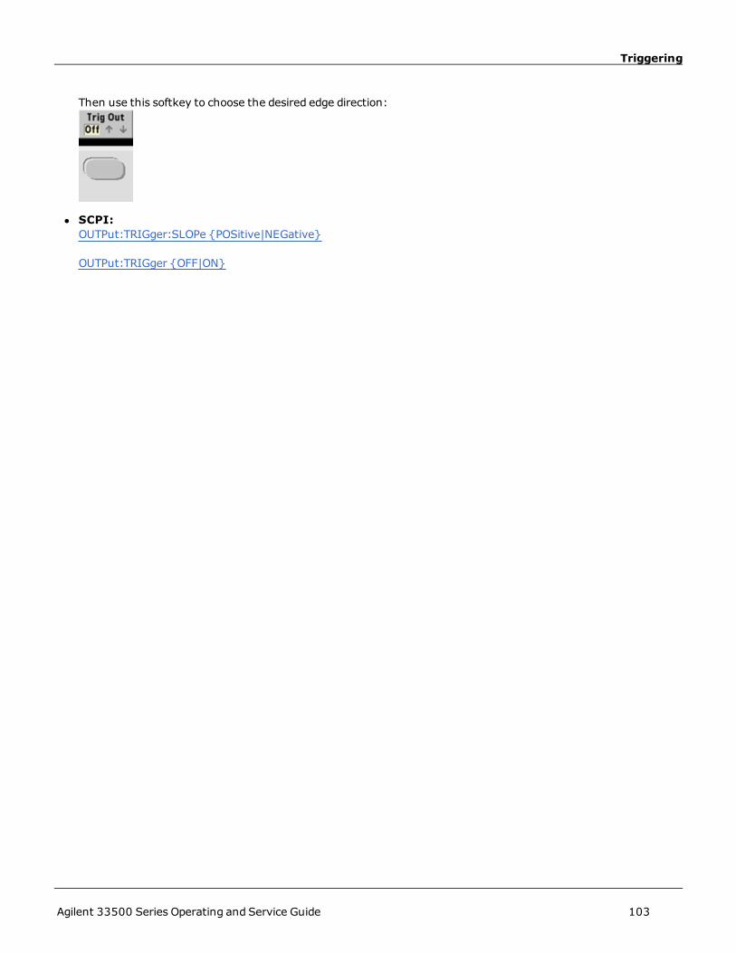
Triggering
Then use this softkey to choose the desired edge direction:
l SCPI:OUTPut:TRIGger:SLOPe {POSitive|NEGative}
OUTPut:TRIGger {OFF|ON}
Agilent 33500 Series Operating and Service Guide 103

Dual Channel Operations
Dual Channel OperationsThis section covers most topics related to dual channel operation. It does not cover the optional IQ Player.
Entering Dual Channel Operation
You enter dual channel configuration by pressing a channel output button, then More, then Dual Channel.
Frequency Coupling
Frequency coupling allows you to couple frequencies or sample rates between channels, either by a constant ratio or off-set between them. Press Freq Cpl to turn frequency coupling on or off, and press Freq Cpl Settings to configurefrequency coupling.
The Freq Cpl Settings softkey opens the menu shown below. The first softkey allows you to specify whether youwant to couple the frequencies with a ratio or an offset, and the second softkey allows you to specify the ratio or offset.
Amplitude Coupling
Amplitude coupling, enabled by the Ampl Cpl softkey, couples the amplitude and offset voltage between the channelsso that changing the amplitude or offset on one channel affects both channels.
Tracking
Tracking, configured by the Tracking softkey, has three modes:Off,On and Invert. When tracking is off, the twochannels operate independently. When tracking is on, they behave as one channel. The thirdmode, Invert, makesthe channels’ outputs inverses of each other, resulting in a differential channel using both outputs.
104 Agilent 33500 Series Operating and Service Guide

Dual Channel Operations
Combine
The Combine feature combines two outputs into one connector. If you choose CH2 from the Channel 1menu, theyare combined on channel 1; choosingCH1 from the Channel 2menu combines them on channel 2.
In the image below, the top waveform is a 100 mVpp, 1 kHz sine wave on channel 1, and the bottom waveform is a100 mVpp, 5 kHz sine wave on channel 2.
The image below shows the two outputs combined on channel 1. Note that the X-axis has been compressed (zoomedout) to show more cycles.
Agilent 33500 Series Operating and Service Guide 105

Dual Channel Operations
The signals being combined do not have to be of the same type; for example, this image shows the same 5 kHz channelon channel 2 combinedwith a 100 mVpp square wave on channel 1.
When signals are combined, the DCOffset values are not added together. Only the DCOffset from the receiving chan-nel is used in the combined output. The figure below shows 50 amV DCOffset added to Channel 1. The 50 mV offsetadded to Channel 2 is ignored.
You may also use Combine with bursts. For example, consider the image below, which includes a 1 kHz sine wave onchannel 1 and three-cycle bursts of a 5 kHz sine wave on channel 2.
When these signals are combined on channel 1, the result is a simple amplitude addition of the two signals, as shownbelow.
106 Agilent 33500 Series Operating and Service Guide

Dual Channel Operations
You also can combine the signals on channel 2, as shown below.
Agilent 33500 Series Operating and Service Guide 107

IQ Player (Optional)
IQ Player (Optional)The optional IQ Player is used to play dual arbitrary waveforms, such as IQ baseband signals.
A dual arbitrary waveform is analogous to a stereomusic file. It has two channels of information that contain the samenumber of samples, always start and end together, and always play at the same sample rate.
File Formats
The instrument's native .ARB and .BARB files can contain either one or two channels of data. These files are typicallycreated in Agilent BenchLink Waveform Builder software, and you can directly play them on the instrument.
You can also directly play files ending in .DAT, .ASC, .I, and .Q. These file formats contain one or two columns of ASCIInumbers ranging between -1.0 and 1.0, in either scientific or decimal notation. The data represents the relative“shape” of the waveform at the current amplitude range.
Finally, you can import one- or two-column data files in .CSV or .TXT format. To import a file, press [Waveforms] >Arb > Arbs > Import Data. This opens a menu interface that quickly guides you through the process of importing afile.
Front Panel
Once you have a dual arbitrary waveform as the active waveform, the tab changes to a purple color, as shown below.
The waveform image is a constellation diagram, but you can change it to a time domain diagram. To do this, press [Sys-tem] > System Setup > Screen Layout. This takes you to the followingmenu:
Pressing the Time softkey changes the graphic to a time domain image:
108 Agilent 33500 Series Operating and Service Guide

IQ Player (Optional)
Balance Adjust
If you pressMore from the [Parameters]menu, you will go to page 2 of the [Parameters]menu:
From this menu, you can press Balance Adjust to open amenu that will allow you specify the balance amplitude gainand channel offsets:
IQ Arb Skew
To compensate for minor channel-channel time skew, begin by pressing either of the channel output buttons and thenpressingMore to go to page 2 of the menu:
On this menu, press IQ Arb Skew to open the followingmenu, which allows you to compensate for up to 4 ns ofskew:
SCPI Commands
There are eight SCPI commands associated with the IQ Player:
Loading Dual Arbitrary Waveforms
DATA:ARB2
DATA:ARB2:DAC
DATA:ARB2:FORMat
Agilent 33500 Series Operating and Service Guide 109

IQ Player (Optional)
Adjusting Playback of Dual Arbitrary Waveforms
FUNCtion:ARB:SKEW[:STATe]
FUNCtion:ARB:SKEW
FUNCtion:ARB:BALance[:STATe]
FUNCtion:ARB:BALance:GAIN
FUNCtion:ARB:BALance:OFFSet
110 Agilent 33500 Series Operating and Service Guide

System-Related Operations
System-Related OperationsThis section covers instrument state storage, power-down recall, error conditions, self test, and display control. Thoughunrelated to waveform generation but is important for instrument operation.
Instrument State Storage
l There are two ways to store and retrieve instrument states:
l Named state files, using front panel or MMEMory:STORe:STATe andMMEMory:LOAD:STATe
l Memory locations 1 through 4, using *SAV and *RCL
l You can also use special storage location 0 with *SAV and *RCL, but location 0 is overwritten by the current instru-ment state on power down.
l Both state storage methods remember the selected function (including arbitrary waveforms), frequency, ampli-tude, DC offset, duty cycle, symmetry, andmodulation parameters.
l If you delete an arbitrary waveform from non-volatile memory after storing the instrument state, the waveformdata is lost and the instrument uses "exponential rise" in its place.
l Stored states are not affected by *RST; a stored state remains until overwritten or specifically deleted.
l Front Panel:
To save a state:
The state file will be created with .sta extension, using the name you specified with the knob and arrows.
To recall a state:
Use the right arrow to expand a folder. To select a file, press Select.
To delete a state:
Agilent 33500 Series Operating and Service Guide 111

System-Related Operations
Use the knob and arrows to select .sta file, and then press Select.
l You can configure instrument to power-down state from location 0 on power up. The factory default is to recall fac-tory default state at power-on.
l Front Panel:
l SCPI: MEMory:STATe:RECall:AUTO
Error Conditions
Up to 20 command syntax or hardware errors can be stored in the instrument's interface-specific error queues. SeeSCPI Error Messages for more information.
l Front Panel:
l SCPI: SYSTem:ERRor?
Beeper Control
The instrument normally beeps when an error is generated from the front-panel or remote interface. You may disablethe beeper, but not the click generated by pressing a front-panel key or turning the knob.
l This setting is non-volatile; it will not be changed by power cycling or *RST.
l Front Panel
l SCPI:SYSTem:BEEPer:STATe {OFF|ON}
112 Agilent 33500 Series Operating and Service Guide

System-Related Operations
SYSTem:BEEPer
Display Screen Saver
The display's backlight normally turns off and blanks the screen after 8 hours of inactivity. You may disable this screensaver from the front panel only.
l This setting is non-volatile; it will not be changed by power cycling or *RST.
l Front Panel:
Display Brightness
You can adjust display brightness (10% to 100%) from the front panel only.
l This setting is non-volatile; it will not be changed by power cycling or *RST.
l Front Panel:
Date and Time
You can set the instrument's date and time clock.
l Front Panel:
l SCPISYSTem:DATE <yyyy>, <mm>, <dd>
SYSTem:TIME <hh>, <mm>, <ss>
Manage Files
You can perform file management tasks, including copying, renaming, deleting, and creating new folders.
Agilent 33500 Series Operating and Service Guide 113

System-Related Operations
l Front-Panel
l You can copy, rename, or delete files or folders. Deleting a folder removes all of the files within the folder, so besure that you want to delete all of the files within the folder.
l The most important softkey isAction, which allows you to specify the operation to perform. Once you havechosen the action to perform, press Browse to select the file to manage. Once you are completely prepared toexecute the task, press Perform.
l SCPI: (see MEMory andMMEMory subsystems).
Self-Test
l A limited power-on self-test occurs when you turn on the instrument to assure you that the instrument is oper-ational. You can also run amore complete self-test. For details, see Self-Test Procedures.
Display Control
For security reasons, or to speed up the rate at which the instrument executes remote interface commands, you maywant to turn off the display. You can also remotely display a message or clear a message on the display.
l The display is enabled when power is cycled, after an instrument reset (*RST), or when you return to local (frontpanel) operation. Press the [Local] key or execute the IEEE-488 GTL (Go To Local) command from the remoteinterface to return to the local state.
l The display state is savedwhen you store the instrument state with *SAV recalled by *RCL.
l Front Panel:
l SCPI:DISPlay
114 Agilent 33500 Series Operating and Service Guide

System-Related Operations
DISPlay:TEXT
DISPlay:TEXT:CLEar
Number Format
The instrument can display numbers on the front panel with periods or commas for the decimal point and digits sep-arator. The default is a period decimal point with commas for digit separation (1.000,000,00 kHz).
l This setting is non-volatile; it will not be changed by power cycling or *RST.
l Front Panel:
l SCPI: (No equivalent command)
Firmware Revision Query
Send *IDN? to determine which revision of firmware is currently installed. The query returns a string of the form:
Agilent Technologies,[Model Number],[10-char Serial Number],A.aa-B.bb-C.cc-DD-EE
l Front Panel:
l SCPI: *IDN?
SCPI Language Version Query
The instrument complies with the rules and conventions of the present version of SCPI (Standard Commands for Pro-grammable Instruments). Use SYSTem:VERSion? to determine the SCPI version with which the instrument complies.The query returns a string in the form "YYYY.V", representing the year and version number for that year (for example,1999.0).
License Installation
The 33500 Series has several optional features that require licenses for installation. To install a license:
1. Install the license file onto a USB drive and insert the USB drive into the instrument’s front panel.
2. Press [System] > System Setup > Install License.
3. Use the knob and arrows to select the file under External, then press Enter.
There are also several SCPI commands associated with license installation.
Agilent 33500 Series Operating and Service Guide 115

Remote Interface Configuration
Remote Interface ConfigurationThe instrument supports remote interface communication over three interfaces: GPIB (optional), USB, and LAN. Allthree are "live" at power up.
l GPIB Interface: Set the instrument's GPIB address connect to your PC using a GPIB cable.
l USB Interface: No configuration; simply connect instrument to PC with a USB cable.
l LAN Interface: By default, DHCP is on, which may enable communication over LAN. The acronym DHCP standsfor Dynamic Host Configuration Protocol, a protocol for assigning dynamic IP addresses to networked devices. Withdynamic addressing, a device can have a different IP address every time it connects to the network.
Connectivity Software and Product CDs
The instrument ships with two CDs:
l Agilent Automation-Ready CD: Contains Agilent IO Libraries Suite software, which must be installed to enableremote-interface operations. The CD auto-starts and provides information on installing the software. Also includesAgilent Technologies USB/LAN/GPIB Connectivity Guide, which contains additional information.
l Agilent 33500 Series Product-Reference CD:Contains instrument drivers, product documentation, and pro-gramming examples. Auto-starts and provides instructions.
GPIB Configuration
Each device on the GPIB (IEEE-488) interface must have a unique whole number address between 0 and 30. Theinstrument ships with a default address of 10, and the GPIB address is displayed at power-on.
l This setting is non-volatile; it will not be changed by power cycling or *RST.
l Your computer’s GPIB interface card address must not conflict with any instrument on the interface bus.
l Front-Panel Operation: Press [System] > I/O Config > GPIB Settings. From this menu, you can set theGPIB address and turn GPIB on or off.
l SCPI:SYSTem:COMMunicate:GPIB:ADDRess <address>
SYSTem:COMMunicate:GPIB:ADDRess?
SYSTem:COMMunicate:ENABle <state>,GPIB
SYSTem:COMMunicate:ENABle? GPIB
LAN Configuration
The following sections describe the primary front-panel LAN configuration functions, including SCPI commands whereapplicable. Some LAN configuration functions that can be performed only via SCPI. See LAN Configuration Introductionfor all LAN configuration commands, and see LAN Configuration Procedure for a procedure to configure the LAN via thefront panel.
Some LAN settings require you to cycle power on the instrument in order for them to be activated.The instrument briefly displays a message when this is the case, so be sure to watch the screenclosely as you change LAN settings.
116 Agilent 33500 Series Operating and Service Guide

Remote Interface Configuration
Resetting the LAN
You can clear the Web Interface password, turn DHCP on, and restart the LAN at any time:
l Front panel:
The message "Performing LAN Reset" is displayedwhile the LAN is reset.
l SCPI: (No equivalent command)
DHCP On/Off
DHCP (Dynamic Host Configuration Protocol) can automatically assign a dynamic IP address to a LAN device. Typicallyeasiest way to configure instrument for LAN.
l This setting is non-volatile; it will not be changed by power cycling or *RST.
l Front Panel:
Finally, toggle the first softkey to DHCP to use DHCP to automatically assign an IP address.
l SCPI: SYSTem:COMMunicate:LAN:DHCP <state>
Tomanually set an IP address, Subnet Mask, or Default Gateway, turn DHCP off, then change IP setup as describedbelow.
IP Address
You can enter a static IP address for the instrument as a four-byte integer expressed in dot notation. Each byte is a dec-imal value, with no leading zeros (for example, 169.254.2.20).
l If DHCP is on, it attempts to assign an IP address to the instrument. If it fails, AutoIP attempts to assign an IPaddress to the instrument.
l Contact your LAN administrator to obtain an IP address.
l This setting is non-volatile; it will not be changed by power cycling or *RST.
Agilent 33500 Series Operating and Service Guide 117

Remote Interface Configuration
l Front Panel:
l Finally, toggle the first softkey toManual and press IP Address to enter a new IP address. Enter the desiredaddress.
l SCPI: SYSTem:COMMunicate:LAN:IPADdress <address>
Subnet Mask
Subnetting allows the LAN administrator to subdivide a network to simplify administration andminimize network traf-fic. The subnet mask indicates the portion of the host address used to indicate the subnet.
l Contact your LAN administrator for details.
l This setting is non-volatile; it will not be changed by power cycling or *RST.
l Front Panel:
l Finally, toggle the first softkey toManual and press Subnet Mask to enter a new subnet mask with the numerickeypad or knob (for example: 255.255.0.0).
l SCPI: SYSTem:COMMunicate:LAN:SMASk "<mask>"
Default Gateway
A gateway is a network device that connects networks. The default gateway setting is the IP address of such a device.
l You need not set a gateway address if using DHCP or AutoIP.
l Contact your LAN administrator for gateway details.
l This setting is non-volatile; it will not be changed by power cycling or *RST.
l Front Panel:
118 Agilent 33500 Series Operating and Service Guide

Remote Interface Configuration
Finally, toggle the first softkey toManual and pressMore andGateway. Then set the appropriate gatewayaddress using the numeric keypad or knob.
l SCPI: SYSTem:COMMunicate:LAN:GATeway "<address>"
Hostname
A hostname is the host portion of the domain name, which is translated into an IP address.
l The instrument receives a unique hostname at the factory, but you may change it. The hostnamemust be uniqueon the LAN.
l The namemust start with letter; other characters can be an upper or lower case letters, numeric digits, or dashes("-").
l This setting is non-volatile; it will not be changed by power cycling or *RST.
l Front Panel:
Finally, pressHost Name and enter the hostname with the knob and arrows. The knob changes the character;cursor arrowsmove between characters.
l SCPI: SYSTem:COMMunicate:LAN:HOSTname "<name>"
Domain Name
A domain name is a registered Internet name that gets translated into an IP address. You cannot set it from the frontpanel or SCPI.
DNS Server
DNS (Domain Name Service) is an Internet service that translates domain names into IP addresses. The DNS serveraddress is the IP address of a server that performs this service.
l Normally, DHCP discovers DNS address information; you only need to change this if DHCP is unused or not func-tional. Contact your LAN administrator for DNS server details.
l This setting is non-volatile; it will not be changed by power cycling or *RST.
l Front Panel:
Agilent 33500 Series Operating and Service Guide 119

Remote Interface Configuration
Finally, toggle the first softkey toManual and pressMore andPrimary DNS or Second DNS to enter a DNSaddress using the numeric keypad or knob.
l SCPI: SYSTem:COMMunicate:LAN:DNS[1|2] "<address>"
Current Configuration (LAN)
l Select the Currently Active Settings display to view the MAC address and current LAN configuration.
l Front Panel:
l SCPI: (No equivalent command)
Display reflects only currently active settings when first displayed; does not update with changes occurring after infor-mation displayed. For example, if DHCP assigns IP address with display open, new IP address will not appear.
If the instrument goes into remote, all LAN changes will be canceled, and the display will go to a different screen. Re-selecting the LAN Settings page will display the new settings if a LAN restart took place.
See SYSTem Subsystem Introduction for additional LAN configuration commands.
Web Interface
The instrument includes a built-in Web Interface. You can use this interface over LAN for remote instrument accessand control via a Java™-enabledWeb browser, such as Microsoft® Internet Explorer.
To use the Web Interface:
1. Establish a LAN connection from your PC to the instrument.
2. Open your PC's Web browser.
3. Launch the instrument's Web Interface by entering the instrument's IP address or fully-qualified hostname in thebrowser address field.
4. Follow the instructions in the Web Interface's on-line help.
120 Agilent 33500 Series Operating and Service Guide

Remote Interface Configuration
USB Configuration
There are no configurable USB parameters. You can retrieve the USB ID string (set by the manufacturer) by using theShow USB Id feature:
l Front Panel:
The USB string appears on the screen. The longest string of digits within the USB ID is the instrument’s serialnumber.
l SCPI: (No equivalent command)
Agilent 33500 Series Operating and Service Guide 121

External Timebase Reference
External Timebase ReferenceThe external timebase reference provides rear panel connectors (10 MHz In and10 MHz Out) and circuitry to allowsynchronization between multiple instruments or to an external 10 MHz clock signal. You can also set the phase offsetof the output waveform from the front panel or over the remote interface.
To align the phase of two instruments, use a dual-channel oscilloscope to compare the output signals:
1. Connect the two instruments, with 10 MHz Out connected to 10 MHz In. Use the instrument with the more pre-cise timebase as the 10 MHz reference output source.
2. Connect instrument outputs to scope channel inputs:
3. Set the same frequency on both instruments. The scope should show the signals to be in sync with regardfrequency, but not phase. (A square wave works well to show the phase difference.)
4. For two-channel instruments, phase sync the two channels to each other. This also synchronizes each channel’smodulating waveforms to the carrier.
Front panel:
SCPI: [SOURce[1|2]:]PHASe:SYNChronize
5. Leaving the phase setting at its default (zero) on the first instrument, use Adjust Phase to adjust the phase ofthe second instrument to align the output signals:
122 Agilent 33500 Series Operating and Service Guide

External Timebase Reference
Out of Phase Aligned
You can use Set 0 Phase to set a new zero-phase reference point with the two instruments now aligned.
l Front-Panel:
Then set the phase angle using the keypad or knob. Once they are aligned, press Set 0 Phase.
l SCPI:[SOURce[1|2]:]PHASe {<angle>|MINimum|MAXimum}
[SOURce[1|2]:]PHASe:REFerence
Agilent 33500 Series Operating and Service Guide 123

Embedded Waveform Editor
Embedded Waveform EditorThe instrument includes an embeddedwaveform editor for creating and editing single-channel arbitrary waveforms inASCII arbitrary waveforms (.ARB suffix). You can enter and edit voltage values directly or by combining up to 12 dif-ferent kinds of standard waveforms, as described in the following sections:
StandardWaveforms
Basic Waveform Editing
Advanced Edit
AdvancedMath
Utility Menu
Standard Waveforms
The embeddedwaveform editor includes the following 12 waveforms:
Sine y = sin(x)
Square A square wave that switches between two voltage levels
Ramp A waveform with linearly rising or falling voltage
Line Line segment
DC A DC voltage
Noise Random noise
Gaussian A gaussian bell curve
Sinc y = sin(x)/x
D-Lorentz The derivative of the Lorentz function. The Lorentz function is y = 1/(x²+1), so theThe D-Lorentz function is y = -2x/(x²+1)².
124 Agilent 33500 Series Operating and Service Guide

Embedded Waveform Editor
Expo Fall Exponential decay: y = e-kx
Expo Rise Exponential rise: y = 1 – e-kx
Haversine y = [1 – cos(x)]/2
When you select a waveform, the instrument displays a screen that allows you to specify the waveform’s parameters,listed below.
Amplitude The peak height above 0 V when the waveform has 0 offset, from 10 μV to 10 V(default 1).
Offset The distance the waveform is shifted up or down relative to 0 V, from -10 to 10 V(default 0).
The Amplitude plus the Offset must be between -10 V and 10 V.
Phase The number of degrees that the waveform is advanced (positive value) or retarded(negative value) from 0 degrees, from -360 to 360 (default 0).
Cycles The number of complete output cycles (a positive integer) that the waveformincludes. Each cycle must have at least 8 points.
Points The number of points the waveform includes, from 8 to 1,000,000 (default 100).You may also extend the memory up to 16,000,000 points.
Because a cycle must have at least 8 points, the number of points divided by the number of cycles must be at least8.
Half Width(D-Lorentz only)
A value that controls the waveform width; larger values make wider curves. Aninteger from 1 to the total number of points in one cycle (default 10).
Fall Factor(Expo Fall only)
A decimal number from -99 to 99 that controls how fast the waveform falls or rises(default -5).
Rise Factor(Expo Rise only)
Full Width(Gaussian only)
The width of the bell curve between the points on the curve that are one-half thecurve's height, from 1 to the number of points in one cycle (default 10).
Symmetry(Ramp only)
The percentage of time (per cycle period) that the ramp rises, a decimal from 0 to100 (default 100).
Zero Crossing
(Sinc only)
The number of times the waveform crosses the horizontal axis on one side of thewaveform, from 0 to 100 (default 10).
Agilent 33500 Series Operating and Service Guide 125

Embedded Waveform Editor
Duty Cycle
(Square only)
The percentage of the time (per cycle period) that the waveform voltage is high,from 0 to 100 (default 50).
Start Level
(Line only)
The voltage at the beginning or end of the line segment.
End Level
(Line only)
Basic Waveform Editing
When you start the embeddedwaveform editor (press [Waveforms] andArb, then Arbs, Edit New, andStartEditor), the opening screen appears. (Note that the samemenu that contains the Edit New softkey also contains anImport CSV softkey. You can use this to import ASCII files from oscilloscopes and other common instruments.)
Edit Points allows you to edit the voltage values of individual points in the waveform. You can also insert and removepoints in the waveform, and you can access the Advanced Edit features, described below. The current screen imageshows the default new arbitrary waveform of 8 points at 0 VDC.
Edit Params allows you to set the waveform’s sample rate, which is the rate (in points per second) in which the wave-form is played. You can specify this value as a rate or as a period. If you change one, the other will recalculate based onthe number of points in the waveform. This feature also allows you to specify whether the waveform is labeled withunits of time or points along the horizontal axis.
126 Agilent 33500 Series Operating and Service Guide

Embedded Waveform Editor
Insert Built-In allows you to insert one of 12 pre-definedwaveforms into the current waveform.
Select Point # allows you to specify where the waveform is to be inserted, and the Choose Wave softkey allows youto specify which one of the 12 waveform types is to be inserted.
Once you have used the arrow keys to select the waveform to insert and pressedOK, the instrument displays theparameters for the waveform to be inserted. Note the up and down arrow softkeys, which you use to select a param-eter for editing. Specify the parameters and pressOK.
Agilent 33500 Series Operating and Service Guide 127

Embedded Waveform Editor
Save allows you to save the current waveform at its current location in the instrument’s internal memory.
Exit Editor closes the waveform editor and resumes normal operation.
If you have unsaved changes, a message gives you the option of staying in the embeddedwaveform editor. After youexit the editor, you will have the option to play the waveform on the waveform generator.
Advanced Edit
As described above, the Edit Pointsmenu includes an Advanced Edit softkey. This softkey allows you to cut, copyand paste portions of the waveform, edit waveform points in a table, and perform mathematical operations on thewaveform.
Cut/Copy/Paste allows you to define a range of the waveform between twomarkers and then cut or copy the wave-form points defined by the markers. Once you have cut or copied the range, you can paste it as many times as desiredby using the Paste softkey.
128 Agilent 33500 Series Operating and Service Guide

Embedded Waveform Editor
Paste Location allows you to paste a range at the start of the waveform, the end of the waveform, or any point withinthe waveform.
Edit Via Table allows you to edit the voltage values of individual points in a table. You can use the knob to scrollthrough the table, or you can use the Point # softkey to directly select any particular point. You can also insert orremove waveform points.
Perform Math allows you to use markers to specify a range of the waveform. You can then add, subtract, or multiplythe voltage values in that range by the voltage values in another waveform.
Agilent 33500 Series Operating and Service Guide 129

Embedded Waveform Editor
Once you have pressedAdd, Subtract, orMultiply, the instrument displays a list of waveforms. Pick the waveformand pressOK.
When you pressOK, the instrument displays a list of parameters that you can use to specify the waveform. In thiscase, the screen below shows that you pickedD-Lorentz. You can also use the From Point and To Point parametersto specify the range of points on which to perform the mathematical operation.
Advanced Math
Advanced Math allows you to perform several different types of operations on the waveform. To open AdvancedMath from the embeddedwaveform editor, press Edit Points > Advanced Edit > Perform Math > AdvancedMath.
The Advanced Mathmenu opens with the following screen. Each of the operations shown below will be describedbelow, using images taken before and after each operation to demonstrate the operations’ effects.
130 Agilent 33500 Series Operating and Service Guide

Embedded Waveform Editor
Invert reflects the waveform across the horizontal axis.
Image Before Invert
Image After Invert
Absolutemultiplies all negative waveform values by -1.
Agilent 33500 Series Operating and Service Guide 131

Embedded Waveform Editor
Image Before Absolute
/>
Image After Absolute
Mirror reverses order of the points in the range.
Image Before Mirror
/>
Image After Mirror
132 Agilent 33500 Series Operating and Service Guide

Embedded Waveform Editor
Scale allows you to scale the waveform’s amplitude and offset. Here, the amplitude scale was set to 180% and the off-set scale was set to 1 V.
Image Before Scale
/>
Image After Scale
Clip allows you to change voltage values outside upper and lower limits to be equal to the limits. In this example, thewaveform was clipped to stay within the -400 mV lower limit and the 700 mV upper limit.
Image Before Clip
/>
Image After Clip
Agilent 33500 Series Operating and Service Guide 133

Embedded Waveform Editor
Trim allows you to use markers to "crop" the waveform so that only the points defined by the marker range remain inthe waveform.
Image Before Trim
/>
Image After Trim
Utility Menu
You can access several utility features by pressing the [System] key from within the embeddedwaveform editor.
134 Agilent 33500 Series Operating and Service Guide

Embedded Waveform Editor
Undo allows you to undo recent operations, subject to the amount of available memory and the size of the undo oper-ation.Redo allows you to redo "undone" tasks, subject to the same limitations.
Pan/Zoom Control allows you to pan or zoom horizontally or vertically. You zoom using a percentage zoom factor,and you pan by specifying a point, and or voltage.
Show All resets the scaling to display the entire waveform.
Agilent 33500 Series Operating and Service Guide 135

Waveform Generation Tutorial
Waveform Generation TutorialThis section describes theory of operation information for several waveform types and instrument operatingmodes.The last two topics include information that may help you improve signal quality.
l Arbitrary Waveforms
l Quasi-Gaussian Noise
l PRBS
l Modulation
l Burst
l Frequency Sweep
l Attributes of AC Signals
l Signal Imperfections
l Ground Loops
Arbitrary Waveforms
Arbitrary waveforms can meet needs not met by the instrument’s standard waveforms. For example, you might need aunique stimulus, or you might want to simulate signal imperfections such as overshoot, ringing, glitching, or noise. Arbi-trary waveforms can be very complex, making them suitable for simulating signals in modern communications sys-tems.
You can create arbitrary waveforms from aminimum of 8 points up to 1,000,000 points. You may also extend thememory up to 16,000,000 points. The instrument stores these numeric data points, known as "samples," in memoryand then converts them into voltages as the waveform is generated. The frequency at which points are read is the"sample rate," and the waveform frequency equals the sample rate divided by the number of points in the waveform.For example, suppose a waveform has 40 points and the sample rate is 10 MHz. The frequency would be (10 MHz)/40= 250 kHz and its period would be 4 µs.
Dual Arbitrary Waveforms
Arbitrary waveformsmay be single-channel waveforms, or (with option IQP), they may be dual-channel arbitrary wave-forms, such as IQ baseband signals. A dual arbitrary waveform is analogous to a stereomusic file. It has two channelsof information that contain the same number of samples, always start and end together, and always play at the samesample rate.
You can control the skew and balance between channels on dual arbitrary waveforms either via commands in the SCPIFUNCtion subsystem or via the front panel.
Waveform Filters
The instrument includes two filters to smooth transitions between points as arbitrary waveforms are generated.
l Normal filter: a wide, flat frequency response, but its step response exhibits overshoot and ringing
l Step filter: a nearly ideal step response, but with more roll-off in its frequency response than the Normal filter
l Off: output changes abruptly between points, with a transition time of approximately 10 ns.
136 Agilent 33500 Series Operating and Service Guide

Waveform Generation Tutorial
Each filter’s cutoff frequency is a fixed fraction of the waveform’s sample rate. The Normal filter’s response is -3 dB at27% of the sample rate and the Step filter’s response is -3 dB at 13% of the sample rate. For example, for an arbitrarywaveform at 100 MSa/s, the Normal filter’s -3 dB frequency bandwidth is 27 MHz.
Waveform Sequencing
The instrument can assemble long, complex sequences of arbitrary waveforms (segments). Switching between seg-ments occurs seamlessly in real time. As an analogy, think of segments as songs in a music player and sequences asplay lists.
Each sequence step specifies a segment and how many times it is played. It also specifies whether the sequence waitsfor a trigger before the next step and how the Sync signal is generated on a step-by-step basis.
For each segment, you can either:
l play the segment from 1 to 1,000,000 times and then advance to the next step
l play the segment once and then stop andwait for a trigger before advancing
l repeat the segment until a trigger occurs and then advance
l repeat the segment until explicitly stopped
Options for Sync signal generation include:
l assert Sync at the beginning of the segment
l negate Sync at the beginning of the segment
l maintain the current Sync state throughout the segment
l assert Sync at the beginning of the segment and negate it at a defined point within the segment
Quasi-Gaussian Noise
The Noise waveform is optimized for both quantitative and qualitative statistical properties. It does not repeat for morethan 50 years of continuous operation. Unlike a true gaussian distribution, there is zero probability of getting a voltagebeyond the instrument’s Vpp setting. The crest factor (peak voltage divided by RMS voltage) is approximately 4.6.
You can vary the Noise bandwidth from 1 mHz to the instrument's maximum bandwidth. The energy in the noise sig-nal is concentrated in a band from DC to the selected bandwidth, so the signal has greater spectral density in the bandof interest when the bandwidth setting is lower. In audio work, for example, you might set the bandwidth to 30 kHz, tomake the audio band signal strength 30 dB higher than if the bandwidth were set to 30 MHz.
PRBS
A Pseudo-Random Bit Sequence (PRBS) has two levels (high and low), and it switches between them in amanner thatis difficult to predict without knowing the sequence generation algorithm. A PRBS is generated by a linear-feedbackshift register (LFSR), shown below.
Agilent 33500 Series Operating and Service Guide 137

Waveform Generation Tutorial
An LFSR is specified by the number of stages it contains andwhich stages ("taps") feed the exclusive-or (XOR) gates inits feedback network. The PRBS output is taken from the last stage. With properly chosen taps, an L-stage LFSRproduces a repetitive PRBS of length 2L-1. The clocking frequency of the LFSR determines the "bit rate" of the PRBS.
The instrument allows you to set L to 7, 9, 11, 15, 20, or 23, resulting in sequences from 127 to 8,388,607 bits inlength.
Modulation
Amplitude Modulation (AM)
The instrument implements two forms of AM
l Double-sideband full-carrier (DSB-FC). DSB-FC has an ITU designation of A3E and is the type used in AM broad-casting.
The equation for DSB-FC is
y(t)= [(1/2)+(1/2)•d•m(t)]•Ac•sin(ω
ct)
where
m(t) is the modulating signal A
cis the carrier amplitude
ωcis the carrier frequency of the carrier
d is the "modulation depth," or fraction of the amplitude range is used by the modulation
For example, a depth setting of 80% varies the amplitude from 10% to 90% of the amplitude setting (90% - 10%= 80%)with either an internal or a full-scale (±5 V) external modulating signal. You may set depth as high as120%, as long as you do not exceed the instrument’s maximum output voltage of (±5 V into 50 Ω, ±10 V intohigh impedance).
In the image below, the top trace represents the modulating signal, and the bottom trace represents the mod-ulated carrier.
138 Agilent 33500 Series Operating and Service Guide

Waveform Generation Tutorial
l Double-sideband suppressed-carrier (DSSC). Many modern communications systems employ DSSC on each of twocarriers that have the same frequency but a 90-degree phase difference. This is called quadrature amplitude mod-ulation (QAM).
The equation for DSSC is y(t)=d•m(t)•sin(ωct)
In DSB-SC, the carrier signal is inverted whenever m(t) < 0. For QAM, the second carrier signal would be cos(ωct),
making it 90 degrees out of phase from the first carrier.
Frequency Modulation (FM)
Frequency modulation varies a carrier signal’s frequency according to the modulating signal:
y(t)=Ac•sin[(ω
c+d•m(t) )•t]
where m(t) is the modulating signal and d is the frequency deviation. FM is called narrowband if the deviation is lessthan 1% of the modulating signal’s bandwidth, andwideband otherwise. You can approximate the modulated signal’sbandwidth with the following equations.
BW ≈ 2•(Modulating Signal Bandwidth) for narrowband FM
BW ≈ 2•(Deviation+Modulating Signal Bandwidth) for wideband FM
In the image below, the top trace represents the modulating signal, and the bottom trace represents the modulatedcarrier.
Agilent 33500 Series Operating and Service Guide 139

Waveform Generation Tutorial
Phase Modulation (PM) PM is similar to FM, but the phase of the carrier waveform is varied, rather than the frequency:
y(t)=sin[ωct+d•m(t) ]
where m(t) is the modulating signal and d is the phase deviation.
Frequency-Shift Keying (FSK)
FSK is similar to FM, except the carrier frequency alternates between two preset values, the carrier frequency and thehop frequency. Sometimes the hop and carrier frequencies are called "Mark" and "Space," respectively. The rate atwhich the switching between these values occurs is determined by an internal timer or the signal on the rear-panel ExtTrig connector. Frequency changes are instantaneous and phase-continuous.
The internal modulating signal is a square wave with 50% duty cycle.
In the image below, the top trace represents the modulating signal, and the bottom trace represents the modulatedcarrier.
Binary Phase Shift Keying (BPSK)
BPSK is similar to FSK, except it is the carrier’s phase, rather than its frequency, that switches between two values. Therate at which the switching between these values occurs is determined by an internal timer or the signal on the rear-panel Ext Trig connector. Phase changes are instantaneous.
140 Agilent 33500 Series Operating and Service Guide

Waveform Generation Tutorial
The internal modulating signal is a square wave with 50% duty cycle.
Pulse Width Modulation (PWM)
PWM is only available for the Pulse waveform, and the pulse width varies according to the modulating signal. Theamount by which the pulse width varies is called the width deviation, and it can be specified as a percentage of thewaveform period (that is, duty cycle) or in units of time. For example, if you specify a pulse with 20% duty cycle andthen enable PWMwith a 5% deviation, the duty cycle varies from 15% to 25% under control of the modulating signal.
Additive Modulation (Sum)
The "Sum" feature adds the modulating signal to the carrier. For example, you can add controlled amounts of variable-bandwidth noise to a signal or create two-tone signals. The instrument's internal modulation generator can producethe same continuous waveform as the main generator, so the Sum function lets you to create many signals that wouldhave required two instruments before.
The Sum feature increases the amplitude of the output signal by the amplitude of the modulating signal. This mightcause the instrument to switch to a higher output-voltage range, resulting in a momentary signal loss. If this is a prob-lem in your application, turn on the Range Hold function. If the voltage increase could damage your device under test,apply Voltage Limits.
Burst
You can configure the instrument to output a waveform with for a specified number of cycles, called a burst. You canuse burst in one of twomodes: N-Cycle Burst (also called "triggered burst") or Gated Burst.
An N-Cycle burst consists of a specific number of waveform cycles (1 to 1,000,000) and is always initiated by a triggerevent. You can also set the burst count to "Infinite" which results in a continuous waveform once the instrument is trig-gered.
In the image below, the top trace is the sync output, and the bottom one is the main output.
Three-Cycle Burst Waveform
For bursts, the trigger source can be an external signal, an internal timer, the key, or a command from the remoteinterface. The input for external trigger signals is the rear-panel Ext Trig connector. This connector accepts TTL-com-patible levels and is referenced to chassis ground (not floating ground). When not used as an input, the Ext Trig
Agilent 33500 Series Operating and Service Guide 141

Waveform Generation Tutorial
connector can be configured as an output to enable the instrument to trigger other instruments at the same time thatits internal trigger occurs.
An N-Cycle burst always begins and ends at the same point in the waveform, called the start phase.
In GATed burst mode, the output waveform is on or off, based on the signal at the rear-panel Ext Trig connector.Select this signal's polarity using BURSt:GATE:POLarity. When the gate signal is true, the instrument outputs a con-tinuous waveform.When the gate signal goes false, the current waveform cycle is completed and the instrument stopsand remains at the voltage level corresponding to the waveform's starting burst phase. For a noise waveform, the out-put stops immediately when the gate signal goes false.
Frequency Sweep
Frequency sweeping is similar to FM, but nomodulating waveform is used. Instead, the instrument sets the outputfrequency based on either a linear or logarithmic function, or a list of up to 128 user-specified frequencies. A linearsweep changes the output frequency by a constant number of Hz per second, and a logarithmic sweep changes thefrequency by a constant number of decades per second. Logarithmic sweeps let you cover wide frequency rangeswhere resolution at low frequencies could be lost with a linear sweep.
Frequency sweeps are characterized by a sweep time (during which the frequency changes smoothly from the startfrequency to the stop frequency), a hold time (during which the frequency stays at the stop frequency), and a returntime (during which the frequency returns smoothly and linearly to the start frequency). Trigger settings determinewhen the next sweep begins.
Attributes of AC Signals
The most common AC signal is a sine wave. In fact, any periodic signal can be represented as the sum of different sinewaves. The magnitude of a sine wave is usually specified by its peak, peak-to-peak, or root-mean- square (RMS) value.All of these measures assume that the waveform has zero offset voltage.
142 Agilent 33500 Series Operating and Service Guide

Waveform Generation Tutorial
A waveform's peak voltage is the maximum absolute value of all of its points. The peak-to-peak voltage is the differencebetween the maximum andminimum. The RMS voltage equals the standard deviation of all waveform points; it alsorepresents the one-cycle average power in the signal, minus the power in any DC component of the signal. Crest factoris the ratio of a signal’s peak value to its RMS value and varies according to waveshape. The table below shows severalcommon waveforms with their respective crest factors and RMS values.
If an average-reading voltmeter is used tomeasure the "DC voltage" of a waveform, the readingmay not agree withthe DCOffset setting. This is because the waveform may have a non-zero average value that would be added to the DCOffset.
You may occasionally see AC levels specified in "decibels relative to 1 milliwatt" (dBm). Since dBm represents a powerlevel, you need to know the signal’s RMS voltage and the load resistance in order to make the calculation.
dBm = 10 x log10(P / 0.001) where P = VRMS2 / RL
For a sine wave into a 50 Ω load, the following table relates dBm to voltage.
dBm RMS Voltage Peak-to-Peak Voltage
+23.98 dBm 3.54 Vrms 10.00 Vpp
+13.01 dBm 1.00 Vrms 2.828 Vpp
+10.00 dBm 707 mVrms 2.000 Vpp
Agilent 33500 Series Operating and Service Guide 143

Waveform Generation Tutorial
dBm RMS Voltage Peak-to-Peak Voltage
+6.99 dBm 500 mVrms 1.414 Vpp
3.98 dBm 354 mVrms 1.000 Vpp
0.00 dBm 224 mVrms 632 mVpp
-6.99 dBm 100 mVrms 283 mVpp
-10.00 dBm 70.7 mVrms 200 mVpp
-16.02 dBm 35.4 mVrms 100 mVpp
-30.00 dBm 7.07 mVrms 20.0 mVpp
-36.02 dBm 3.54 mVrms 10.0 mVpp
-50.00 dBm 0.707 mVrms 2.00 mVpp
-56.02 dBm 0.354 mVrms 1.00 mVpp
For 75 Ω or 600 Ω loads, use the following conversions.
dBm (75 Ω) = dBm (50 Ω) – 1.76 dBm (600 Ω) = dBm (50 Ω) – 10.79
Signal Imperfections
For sine waves, common signal imperfections are easiest to describe and observe in the frequency domain, using a spec-trum analyzer. Any output signal component with a frequency different from the fundamental (or "carrier") is con-sidered to be distortion. Those imperfections can be categorized as harmonic distortion, non-harmonic spurious, orphase noise, and they are specified in decibels relative to the carrier level, or "dBc."
Harmonic Distortion
Harmonic components occur at integer multiples of the fundamental frequency and are usually created by non-linearcomponents in the signal path. At low signal amplitudes, another possible source of harmonic distortion is the Sync sig-nal, which is a square wave with many strong harmonic components that can couple into the main signal. AlthoughSync is highly isolated from the instrument's main signal outputs, coupling can occur in external cabling. For bestresults, use high-quality coaxial cables with double or triple shields. If Sync is not required, leave it unconnected or off.
Non-Harmonic Spurious
One source of non-harmonic spurious components (called "spurs") is the digital-to-analog converter (DAC) that con-verts the digital waveform values into voltage. Non-linearity in this DAC gives rise to harmonics that can be higher thanthe Nyquist frequency andwill therefore be aliased to a lower frequency. For example, the fifth harmonic of 30 MHz(150 MHz) could create a spur at 100 MHz.
Another source of non-harmonic spurs is the coupling of unrelated signal sources (such as the embedded controller’sclocks) into the output signal. These spurs usually have constant amplitude and are most troublesome at signal ampli-tudes below 100 mVpp. For optimal signal purity at low amplitudes, keep the instrument’s output level relatively highand use an external attenuator.
144 Agilent 33500 Series Operating and Service Guide

Waveform Generation Tutorial
Phase Noise
Phase noise results from small, instantaneous changes in the output frequency ("jitter"). On a spectrum analyzer, itappears as a rise in the apparent noise floor near the frequency of the output signal. The phase noise specification rep-resents the amplitudes of the noise in 1 Hz bands located 1 kHz, 10 kHz, and 100 kHz away from a 30-MHz sine wave.Be aware that spectrum analyzers also have phase noise, so the levels you readmay include analyzer phase noise.
Quantization Noise
Finite resolution in the waveform DAC causes voltage quantization errors. Assuming the errors are uniformly dis-tributed over a range of ±0.5 least-significant bit, the equivalent noise level for standard waveforms is approximately -95 dBc. At this level, other sources of noise in the instrument dominate. Quantization noise can be of concern, though,in arbitrary waveforms that do not use the whole range of DAC codes (-32767 to +32767). Scale arbitrary waveformsto use the entire range, if possible.
Ground Loops
The signal-generation portion of the instrument is isolated from chassis (earth) ground. This helps eliminate groundloops in your system and also allows you to reference the output signal to voltages other than ground. The illustrationbelow shows the instrument connected to a load through a coaxial cable. Any difference in ground potentials (V
GND)
will tend to drive current IGND through the shield of the cable, thus causing a voltage drop due to the shield’s imped-ance (Z
SHIELD). This voltage (I
GNDx Z
SHIELD) appears as an error in the load voltage. However, since the instrument is
isolated, there is a high series impedance (typically >1 MΩ) in parallel with 50 nF) to oppose the flow of IGND
andthereby minimize this effect.
At frequencies above a few kHz, a coaxial cable’s shield becomes inductive, rather than resistive, and the cable beginsto act like a transformer. When this happens, voltage drops in the shield due to I
GNDtend to be offset by equal voltages
Agilent 33500 Series Operating and Service Guide 145

Waveform Generation Tutorial
in the center conductor, thereby reducing the effects of ground loops at higher frequencies. Coaxial cables with two orthree braided shields are much better than those with single- braided or foil shields because they have lower resistanceand therefore become transformers at lower frequencies.
To reduce errors due to ground loops, connect the instrument to the load using a high-quality coaxial cable and groundit at the load through the cable’s shield. If possible, make sure the instrument and the load are connected to the sameelectrical outlet to minimize further differences in ground potential.
Be aware that the outer shells of the Sync andModulation In connectors are connected to those of the main outputconnector(s). Cables attached to Sync and/orModulation In are therefore potential sources of ground loops. Also beaware that attempting to drive those connector shells to different voltages can cause high current to flow through theinstrument, possibly causing damage.
146 Agilent 33500 Series Operating and Service Guide

SCPI Programming Reference
SCPI Programming ReferenceThis section describes the SCPI programming language for the instrument.
Introduction to SCPI Language
Alphabetical List of SCPI Commands andQueries
Programming Examples
CommandQuick Reference
Factory Reset State
SCPI Error Messages
Agilent 33500 Series Operating and Service Guide 147

Introduction to the SCPI Language
Introduction to the SCPI LanguageSCPI (Standard Commands for Programmable Instruments) is an ASCII-based instrument command languagedesigned for test andmeasurement instruments. SCPI commands are based on a hierarchical structure, also known asa tree system. In this system, associated commands are grouped together under a common node or root, thus formingsubsystems. A portion of the OUTPut subsystem is shown below to illustrate the tree system.
OUTPut: SYNC {OFF|0|ON|1}
SYNC:MODE {NORMal|CARRier} POLarity {NORMal|INVerted}
OUTPut is the root keyword, SYNC is a second-level keyword, andMODE andPOLarity are third-level keywords. Acolon ( : ) separates a command keyword from a lower-level keyword.
Syntax Conventions
The format used to show commands is illustrated below:
[SOURce[1|2]:]VOLTage:UNIT {VPP|VRMS|DBM}
[SOURce[1|2]:]FREQuency:CENTer {<frequency>|MINimum|MAXimum}
The command syntax showsmost commands (and some parameters) as a mixture of upper- and lower-case letters.The upper-case letters indicate the abbreviated spelling for the command. For shorter program lines, you can send theabbreviated form. For better program readability, you can send the long form.
For example, in the above syntax statement, VOLT and VOLTAGE are both acceptable forms. You can use upper- orlower-case letters. Therefore, VOLTAGE, volt, and Volt are all acceptable. Other forms, such as VOL and VOLTAG, arenot valid andwill generate an error.
l Braces ( { } ) enclose the parameter choices for a given command string. The braces are not sent with the com-mand string.
l A vertical bar ( | ) separates multiple parameter choices for a given command string. For example,{VPP|VRMS|DBM} in the above command indicates that you can specify "VPP", "VRMS", or "DBM". The bar is notsent with the command string.
l Triangle brackets in the second example ( < > ) indicate that you must specify a value for the enclosed parameter.For example, the above syntax statement shows the <frequency> parameter enclosed in triangle brackets. Thebrackets are not sent with the command string. You must specify a value for the parameter (for example"FREQ:CENT 1000") unless you select another option shown in the syntax (for example "FREQ:CENTMIN").
l Some syntax elements (for example nodes and parameters) are enclosed in square brackets ( [ ]). This indicatesthat the element is optional and can be omitted. The brackets are not sent with the command string. If you do notspecify a value for an optional parameter, the instrument chooses a default value. In the examples above the"SOURce[1|2]" indicates that you may refer to source channel 1 either by "SOURce", or by "SOURce1", or by"SOUR1" or by "SOUR". In addition, since the whole SOURce node is optional (in brackets) you also may refer tochannel 1 by entirely leaving out the SOURce node. This is because Channel 1 is the default channel for theSOURce language node. On the other hand, to refer to Channel 2, you must use either "SOURce2" or "SOUR2" inyour program lines.
148 Agilent 33500 Series Operating and Service Guide

Introduction to the SCPI Language
Command Separators
A colon ( : ) is used to separate a command keyword from a lower-level keyword. You must insert a blank space to sep-arate a parameter from a command keyword. If a command requires more than one parameter, you must separateadjacent parameters using a comma as shown below:
APPL:SIN 455E3,1.15,0.0
In this example, the APPLy command is specifying a Sine wave at a frequency of 455 KHz, with an amplitude of 1.15volts, and a DC offset of 0.0 volts.
A semicolon ( ; ) is used to separate commands within the same subsystem, and can also minimize typing. For exam-ple, sending the following command string:
TRIG:SOUR EXT; COUNT 10
is the same as sending the following two commands:
TRIG:SOUR EXT
TRIG:COUNT 10
Using the MIN, MAX, and DEF Parameters
For many commands, you can substitute "MIN" or "MAX" in place of a parameter. In some cases you may also sub-stitute "DEF". For example, consider the following command:
[SOURce[1|2]:]APPLy:DC [{<frequency>|DEF} [,{<amplitude>|DEF} [,{<offset>|MIN|MAX|DEF}]]]
Instead of selecting a specific value for the <offset> parameter, you can substitute MIN to set the offset to its mini-mum value, MAX to set the offset to its maximum value. You can also specify DEF to set the default value for eachparameter: <frequency>, <amplitude>, and<offset>.
Querying Parameter Settings
You can query the current value of most parameters by adding a question mark ( ? ) to the command. For example, thefollowing command sets the trigger count to 10 readings:
TRIG:COUN 10
You can then query the count value by sending:
TRIG:COUN?
You can also query the minimum or maximum count allowed as follows:
TRIG:COUN? MIN
TRIG:COUN? MAX
Agilent 33500 Series Operating and Service Guide 149

Introduction to the SCPI Language
SCPI Command Terminators
A command string sent to the instrument must terminate with a <new line> (<NL>) character. The IEEE-488 EOI(End-Or-Identify)message is interpreted as a <NL> character and can be used to terminate a command string in placeof a <NL> character. A <carriage return> followed by a <NL> is also accepted. Command string termination willalways reset the current SCPI command path to the root level.
For every SCPI message that includes a query and is sent to the instrument, the instrument ter-minates the returned response with a <NL> or line-feed character (EOI). For example, if"DISP:TEXT?" is sent, the response is terminated with a <NL> after the string of data that isreturned. If a SCPI message includes multiple queries separated by semicolons (for example"DISP?;DISP:TEXT?"), the returned response is again terminated by a <NL> after the response tothe last query. In either case, the program must read this <NL> in the response before anothercommand is sent to the instrument, or an error will occur.
IEEE-488.2 Common Commands
The IEEE-488.2 standard defines a set of common commands that perform functions such as reset, self-test, andstatus operations. Common commands always begin with an asterisk ( * ), are three characters in length, andmayinclude one or more parameters. The command keyword is separated from the first parameter by a blank space. Use asemicolon ( ; ) to separate multiple commands as shown below:
*RST; *CLS; *ESE 32; *OPC?
SCPI Parameter Types
The SCPI language defines several data formats to be used in program messages and response messages.
Numeric Parameters
Commands that require numeric parameters will accept all commonly used decimal representations of numbers includ-ing optional signs, decimal points, and scientific notation. Special values for numeric parameters such as MIN, MAX, andDEF are also accepted. You can also send engineering unit suffixes with numeric parameters (e.g., M, k, m, or u). If acommand accepts only certain specific values, the instrument will automatically round the input numeric parametersto the accepted values. The following command requires a numeric parameter for the frequency value:
[SOURce[1|2]:]FREQuency:CENTer {<frequency>|MINimum|MAXimum}
Because the SCPI parser is case-insensitive, there is some confusion over the letter "M" (or "m").For your convenience, the instrument interprets "mV" (or "MV") as millivolts, but "MHZ" (or"mhz") as megahertz. Likewise "MΩ" (or "mΩ") is interpreted as megohms. You can use the prefix"MA" for mega. For example, "MAV" is interpreted as megavolts.
Discrete Parameters
Discrete parameters are used to program settings that have a limited number of values (like IMMediate, EXTernal, orBUS). They may have a short form and a long form just like command keywords. You can mix upper- and lower-case
150 Agilent 33500 Series Operating and Service Guide

Introduction to the SCPI Language
letters. Query responses will always return the short form in all upper-case letters. The following command requires adiscrete parameter for the voltage units:
[SOURce[1|2]:]VOLTage:UNIT {VPP|VRMS|DBM}
Boolean Parameters
Boolean parameters represent a single binary condition that is either true or false. For a false condition, the instrumentwill accept "OFF" or "0". For a true condition, the instrument will accept "ON" or "1". When you query a boolean set-ting, the instrument will always return "0" or "1". The following command requires a boolean parameter:
DISPlay {OFF|0|ON|1}
ASCII String Parameters
String parameters can contain virtually any set of ASCII characters. A stringmust begin and endwith matchingquotes; either with a single quote or a double quote. You can include the quote delimiter as part of the string by typingit twice without any characters in between. The following command uses a string parameter:
DISPlay:TEXT <quoted string>
For example, the following command displays the message "WAITING..." on the instrument's front panel (the quotesare not displayed).
DISP:TEXT "WAITING..."
You can also display the samemessage using single quotes.
DISP:TEXT 'WAITING...'
Using Device Clear
Device Clear is an IEEE-488 low-level bus message that you can use to return the instrument to a responsive state. Dif-ferent programming languages and IEEE-488 interface cards provide access to this capability through their own uniquecommands. The status registers, the error queue, and all configuration states are left unchangedwhen a Device Clearmessage is received.
Device Clear performs the following actions:
l If a measurement is in progress, it is aborted.l The instrument returns to the trigger "idle" state.l The instrument's input and output buffers are cleared.l The instrument is prepared to accept a new command string.
The ABORt command is the recommendedmethod to terminate an instrument operation.
Agilent 33500 Series Operating and Service Guide 151

Alphabetical List of SCPI Commands and Queries
Alphabetical List of SCPI Commands and QueriesAM Subsystem
APPLy Subsystem
BPSK Subsystem
BURSt Subsystem
CALibration Subsystem
DATA Subsystem
DISPlay Subsystem
FM Subsystem
FREQuency Subsystem
FSKey Subsystem
FUNCtion Subsystem
HCOPy Subsystem
IEEE-488.2 Common Commands
INITiate Subsystem
LIST Subsystem
LXI Subsystem
MARKer Subsystem
MEMory Subsystem
MMEMory Subsystem
OUTPut Subsystem
PHASe Subsystem
PM Subsystem
PWM Subsystem
RATE Subsystem
ROSC Subsystem
SOURce Subsystem
STATus Subsystem
SUM Subsystem
SWEep Subsystem
SYSTem Subsystem
TRIGger Subsystem
VOLTage Subsystem
Other Commands
ABORt
COMBine:FEED
FORMat:BORDer
TRACk
UNIT:ANGLe
152 Agilent 33500 Series Operating and Service Guide

Internal Function Waveforms
Internal Function WaveformsThe following are the internal function waveforms.
l SINusoid: a sine wave, no phase shift.
l SQUare: a square wave, 50% duty cycle.
l RAMP: ramp, 100% symmetry.
l NRAMp: negative ramp, 0% symmetry.
Agilent 33500 Series Operating and Service Guide 153

Internal Function Waveforms
l TRIangle: ramp, 50% symmetry.
l NOISe: gaussian noise; if NOISe is the internal function, it cannot also be the carrier.
l PRBS: pseudo-random binary sequence modulation; if PRBS is the internal function, it cannot also be the carrier.
l ARBitrary: arbitrary waveform; default is exponential rise; if ARB is the internal function, it cannot also be the car-rier.
See Also
AM Subsystem
FM Subsystem
PM Subsystem
PWM Subsystem
SUM Subsystem
154 Agilent 33500 Series Operating and Service Guide

ABORt
ABORtHalts a sequence, list, sweep, or burst, even an infinite burst. Also causes trigger subsystem to return to idle state. IfINITiate:CONTinuous is ON, instrument immediately proceeds to wait-for-trigger state.
Parameter Typical Return
(none) (none)
Halt the items listed above:ABOR
l Halts any triggered action (triggered list, triggered sweep, triggered burst, triggered arbitrary waveform playback).
l ABORt has no effect when instrument is in normal or modulatedmodes, except for sequenced arbitrary wave-forms, lists, bursts, and sweeps. If instrument is running a sequence, list, burst, or sweep, ABORt restarts thestopped item with the current INIT and trigger conditions.
l When ABORt occurs in list mode, the frequency goes back to the "normal" mode frequency until the first triggeroccurs. After the first trigger, the first frequency in the list will be used.
l If ABORt executed during sweep, sweep returns to starting sweep frequency.
l ABORt always applies to both channels in a two-channel instrument.
Agilent 33500 Series Operating and Service Guide 155

AM Subsystem
AM SubsystemThe AM subsystem allows you to add amplitude modulation (AM) to a carrier waveform.
Example
To generate an amplitude modulation (AM) waveform:
1. Configure carrier waveform: Use FUNCtion, FREQuency, VOLTage, and VOLTage:OFFSet to specify the carrierwaveform's function, frequency, amplitude, and offset.
2. Select mode of Amplitude Modulation: AM:DSSC
3. Select modulation source (internal, external, CH1, or CH2): AM:SOURce. For an external source, you canskip steps 4 and 5 below.
4. Select modulating waveform: AM:INTernal:FUNCtion
5. Set modulating frequency: AM:INTernal:FREQuency
6. Set modulation depth: AM[:DEPTh]
7. Enable AM:AM:STATe:ON
The following code produces the oscilloscope image shown below.
FUNCtion SQU
FREQuency +1.0E+04
VOLTage +1
VOLTage:OFFset 0.0
AM:SOURce INT
AM:DSSC 0
AM:DEPTh +120
AM:INTernal:FUNCtion TRI
AM:INTernal:FREQ 5E+02
AM:STATe 1
OUTPut1 1
156 Agilent 33500 Series Operating and Service Guide
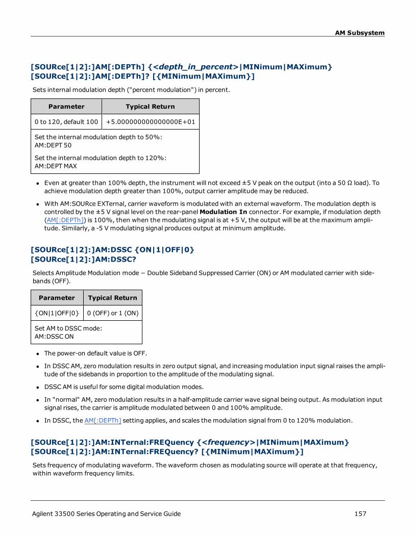
AM Subsystem
[SOURce[1|2]:]AM[:DEPTh] {<depth_in_percent>|MINimum|MAXimum}[SOURce[1|2]:]AM[:DEPTh]? [{MINimum|MAXimum}]
Sets internal modulation depth ("percent modulation") in percent.
Parameter Typical Return
0 to 120, default 100 +5.000000000000000E+01
Set the internal modulation depth to 50%:AM:DEPT 50
Set the internal modulation depth to 120%:AM:DEPTMAX
l Even at greater than 100% depth, the instrument will not exceed±5 V peak on the output (into a 50 Ω load). Toachieve modulation depth greater than 100%, output carrier amplitude may be reduced.
l With AM:SOURce EXTernal, carrier waveform is modulated with an external waveform. The modulation depth iscontrolled by the ±5 V signal level on the rear-panelModulation In connector. For example, if modulation depth(AM[:DEPTh]) is 100%, then when the modulating signal is at +5 V, the output will be at the maximum ampli-tude. Similarly, a -5 Vmodulating signal produces output at minimum amplitude.
[SOURce[1|2]:]AM:DSSC {ON|1|OFF|0}[SOURce[1|2]:]AM:DSSC?
Selects Amplitude Modulation mode − Double Sideband Suppressed Carrier (ON) or AMmodulated carrier with side-bands (OFF).
Parameter Typical Return
{ON|1|OFF|0} 0 (OFF) or 1 (ON)
Set AM to DSSCmode:AM:DSSCON
l The power-on default value is OFF.
l In DSSC AM, zeromodulation results in zero output signal, and increasingmodulation input signal raises the ampli-tude of the sidebands in proportion to the amplitude of the modulating signal.
l DSSC AM is useful for some digital modulation modes.
l In "normal" AM, zeromodulation results in a half-amplitude carrier wave signal being output. As modulation inputsignal rises, the carrier is amplitude modulated between 0 and 100% amplitude.
l In DSSC, the AM[:DEPTh] setting applies, and scales the modulation signal from 0 to 120%modulation.
[SOURce[1|2]:]AM:INTernal:FREQuency {<frequency>|MINimum|MAXimum}[SOURce[1|2]:]AM:INTernal:FREQuency? [{MINimum|MAXimum}]
Sets frequency of modulating waveform. The waveform chosen asmodulating source will operate at that frequency,within waveform frequency limits.
Agilent 33500 Series Operating and Service Guide 157

AM Subsystem
Parameter Typical Return
1 μHz to the maximum allowed for the internal function. Default 100 Hz +1.000000000000000E+04
Set the modulating frequency to 10 kHz:AM:INT:FUNC 10000
l When you select an arbitrary waveform as the modulating source, the frequency changes to the frequency of thearbitrary waveform, which is based on the sample rate and the number of points in the arbitrary waveform.
l When using an arbitrary waveform for the modulating source, changing this parameter also changes the cachedmetadata representing the aribtrary waveform's sample rate. You can also change the modulating frequency of anarbitrary waveform with FUNCtion:ARBitrary:FREQuency, FUNCtion:ARBitrary:PERiod, and FUNC-tion:ARBitrary:SRATe. These commands and the modulation frequency command are directly coupled in order tokeep the arbitrary waveform behaving exactly as it was last played. If you later turn modulation off and select thatsame arbitrary waveform as the current function, its sample rate (and corresponding frequency based upon thenumber of points) will be the same as it was when played as the modulation source.
l If the internal function is TRIangle, UpRamp, or DnRamp, the maximum frequency limited to 200 kHz. If the inter-nal function is PRBS, the frequency refers to bit rate and is limited to 50 Mbps.
l This command should be used only with the internal modulation source (AM:SOURce INTernal).
[SOURce[1|2]:]AM:INTernal:FUNCtion <function>[SOURce[1|2]:]AM:INTernal:FUNCtion?
Selects shape of modulating waveform.
Parameter Typical Return
{SINusoid|SQUare|RAMP|NRAMp|TRIangle|NOISe|PRBS|ARB}, defaultSINusoid, default SINusoid.View internal function waveforms.
SIN, SQU, RAMP, NRAM, TRI, NOIS,PRBS, or ARB
Select a sine wave as the modulating waveform.AM:INT:FUNC SIN
l This command should be used only with the internal modulation source (AM:SOURce INTernal).
l Pulse and DC cannot be carrier waveform for AM.
158 Agilent 33500 Series Operating and Service Guide

[SOURce[1|2]:]AM:SOURce {INTernal|EXTernal|CH1|CH2}[SOURce[1|2]:]AM:SOURce?[SOURce
[SOURce[1|2]:]AM:SOURce {INTernal|EXTernal|CH1|CH2}[SOURce[1|2]:]AM:SOURce?
[SOURce[1|2]:]BPSK:SOURce {INTernal|EXTernal}[SOURce[1|2]:]BPSK:SOURce
[SOURce[1|2]:]FM:SOURce {INTernal|EXTernal|CH1|CH2}[SOURce[1|2]:]FM:SOURce
[SOURce[1|2]:]FSKey:SOURce {INTernal|EXTernal}[SOURce[1|2]:]FSKey:SOURce
[SOURce[1|2]:]PM:SOURce {INTernal|EXTernal|CH1|CH2}[SOURce[1|2]:]PM:SOURce
[SOURce[1|2]:]PWM:SOURce {INTernal|EXTernal|CH1|CH2}[SOURce[1|2]:]PWM:SOURce?Select the source of the modulating signal.
Parameter Typical Return
{INTernal|EXTernal|CH1|CH2}, default INTernal. BPSK and FSKey can-not accept CH1 or CH2
INT, EXT, CH1, or CH2
Select external modulation source:AM:SOUR EXT (could also substitute FM, BPSK, FSK, PM, or PWM for AM)
Remarks
l If you select EXTernal, the carrier waveform is modulated with an external waveform. Specifically:
l AM:The modulation depth is controlled by the ±5 V signal level on the rear-panelModulation In connector.For example, if modulation depth (AM[:DEPTh]) is 100%, then when the modulating signal is at +5 V, the out-put will be at the maximum amplitude. Similarly, a -5 Vmodulating signal produces output at minimum ampli-tude.
l FM:If you select the Externalmodulating source, the deviation is controlled by the ±5 V signal level on therear-panelModulation In connector.For example, if the frequency deviation is 100 kHz, then a +5 V signallevel corresponds to a 100 kHz increase in frequency.Lower external signal levels produce less deviation andnegative signal levels reduce the frequency below the carrier frequency.
l PM:With the External modulating source, deviation is controlled by the ±5 V signal level on the rear-panelModulation In connector. For example, if you have set the frequency deviation to 180 degrees, then a +5 Vsignal level corresponds to a +180 degree phase deviation. Lower external signal levels produce less deviation,and negative signal levels produce negative deviation.
Agilent 33500 Series Operating and Service Guide 159

[SOURce[1|2]:]AM:SOURce {INTernal|EXTernal|CH1|CH2}[SOURce[1|2]:]AM:SOURce?[SOURce
l Pulse as Selected Function: The pulse width or pulse duty cycle deviation is controlled by the ±5 V signallevel present on the rear-panelModulation In connector. For example, if you have set the pulse width devi-ation to 50 μs using the PWM:DEViation command, then a +5 V signal level corresponds to a 50 μs widthincrease. Lower external signal levels produce less deviation.
l With EXTernal source, the output phase (BPSK) or frequency (FSK) is determined by the signal level on the rear-panel Ext Trig connector. When a logic low is present, the carrier phase or carrier frequency is output. When alogic high is present, the phase shifted phase or hop frequency is output.
l The maximum external BPSK rate is 1 MHz, and the maximum FSK rate is 1 MHz.
l Note: the connector used for externally-controlled BPSK or FSK waveforms (Trig In) is not the same connectorthat is used for externally-modulated AM, FM, PM, and PWMwaveforms (Modulation In). When used for BPSK orFSK, the Trig In connector does not have adjustable edge polarity and is not affected by the TRIGger[1|2]:SLOPecommand.
l With INTernal source, the rate at which output phase (BPSK) or frequency (FSKey) "shifts" between the carrierphase or frequency and the alternate phase or frequency is determined by the BPSK rate (BPSK:INTernal:RATE) orFSK rate (FSKey:INTernal:RATE).
l A channel may not be its own modulation source.
See Also
AM Subsystem
BPSK Subsystem
FM Subsystem
FSKey Subsystem
PM Subsystem
PWM Subsystem
160 Agilent 33500 Series Operating and Service Guide

[SOURce[1|2]:]AM:STATe {ON|1|OFF|0}[SOURce[1|2]:]AM:STATe?[SOURce[1|2]:]BPSK:STATe
[SOURce[1|2]:]AM:STATe {ON|1|OFF|0}[SOURce[1|2]:]AM:STATe?
[SOURce[1|2]:]BPSK:STATe {ON|1|OFF|0}[SOURce[1|2]:]BPSK:STATe
[SOURce[1|2]:]FM:STATe {ON|1|OFF|0}[SOURce[1|2]:]FM:STATe
[SOURce[1|2]:]FSKey:STATe {ON|1|OFF|0}[SOURce[1|2]:]FSKey:STATe
[SOURce[1|2]:]PM:STATe {ON|1|OFF|0}[SOURce[1|2]:]PM:STATe
[SOURce[1|2]:]PWM:STATe {ON|1|OFF|0}[SOURce[1|2]:]PWM:STATe?Enables or disables modulation.
Parameter Typical Return
{ON|1|OFF|0}, default OFF 0 (OFF) or 1 (ON)
Enable AM (could also substitute FM, BPSK, FSK, PM, or PWM):AM:STAT ON
l To avoidmultiple waveform changes, enable modulation after configuring the other modulation parameters.
l Only one modulation modemay be enabled at a time.
l The instrument will not enable modulation with sweep or burst enabled. When you enable modulation, the sweepor burst mode is turned off.
l PWM is allowed only when pulse is the selected function.
See Also
AM Subsystem
BPSK Subsystem
FM Subsystem
FSKey Subsystem
PM Subsystem
PWM Subsystem
Agilent 33500 Series Operating and Service Guide 161

APPLy Subsystem
APPLy SubsystemThe APPLy subsystem allows you to configure entire waveforms with one command. The general form of an APPLy com-mand is shown below:
[SOURce[1|2]:]APPLy:<function> [<frequency> [,<amplitude> [,<offset>]]]
For example,
APPLy:SIN 1e4,1,0.1
replaces the following commands:
FUNCtion SINFREQ 1e4VOLT 1VOLT:OFF 0.1OUTP ON
Not only is APPLy shorter, it avoids settings conflicts that occur when sending commands individually. In addition,APPLy performs the following operations:
l Sets trigger source to IMMediate (equivalent to TRIGger[1|2]:SOURce IMMediate).
l Turns off any modulation, sweep, or burst mode currently enabled and places the instrument in continuous wave-form mode.
l Turns on the channel output (OUTPut ON) without changing output termination setting (OUTPut[1|2]:LOAD).
l Overrides the voltage autorange setting and enables autoranging (VOLTage:RANGe:AUTO).
The instrument can generate eight types of waveforms: DC voltage, gaussian noise, PRBS, pulse, ramp/triangle wave,sine wave, square wave and arbitrary (user) waveform.Waveform-specific settings exist in the FUNCtion subsystem.
You can also query current output configuration (APPLy?).
General Remarks
Amplitude
l Changing amplitude may briefly disrupt output at certain voltages due to output attenuator switching. The ampli-tude is controlled, however, so the output voltage will never exceed the current setting while switching ranges. Toprevent this disruption, disable voltage autoranging using VOLTage:RANGe:AUTOOFF. The APPLy command auto-matically enables autoranging.
l Limits Due to Output Termination: The offset range depends on the output termination setting. For example, ifyou set offset to 100 mVDC and then change output termination from 50 Ω to "high impedance," the offset volt-age displayed on the front panel doubles to 200 mVDC (no error is generated). If you change from "high imped-ance" to 50 Ω, the displayed offset voltage will be halved. See OUTPut[1|2]:LOAD for details.
l Limits Due to Unit Selection: The amplitude limits are determined by the output units selected.
l You cannot specify output amplitude in dBm if output termination is set to high impedance.The units are auto-matically converted to Vpp.
162 Agilent 33500 Series Operating and Service Guide

APPLy Subsystem
Commands and Queries
APPLy?
APPLy:ARBitrary
APPLy:DC
APPLy:NOISe
APPLy:PRBS
APPLy:PULSe
APPLy:RAMP
APPLy:SINusoid
APPLy:SQUare
APPLy:TRIangle
[SOURce[1|2]:]APPLy?
Queries the output configuration.
Parameter Typical Return
(none) "SIN +5.000000000000000E+03,+3.0000000000000E+00,-2.5000000000000E+00"
Return the configuration for a 5 kHz, 3 V sine wave with a -2.5 VDC offset.APPLY?
l The function, frequency, amplitude, and offset are returned as shown above. The amplitude, but not the offset, isreturned as specified by VOLTage:UNIT.
[SOURce[1|2]:]APPLy:ARBitrary [{<sample_rate>|MIN|MAX|DEF} [,{<amplitude>|MIN|MAX|DEF} [,{<offset>|MIN|MAX|DEF}]]]
Outputs arbitrary waveform selected by FUNCtion: ARBitrary, using the specified sample rate, amplitude, and offset.
Parameter Typical Return
<sample_rate> from 1 µSa/s to 250 MSa/s, default 40 kSa/s (none)
<amplitude> from 1 mVpp to 10 Vpp into 50 Ω, 2 mVpp to 20 Vpp into an open circuit,default 100 mVpp into 50 Ω
<offset> is the DC offset voltage (default 0), from ±5 VDC into 50 Ω, or from ±10 VDCinto an open circuit.
Output the arbitrary waveform selected using FUNCtion:ARBitrary:APPLy:ARBitrary 1 KHZ, 5.0, -2.5 V
Agilent 33500 Series Operating and Service Guide 163

APPLy Subsystem
General
l Setting a sample rate when not in the ARBmode will not change the frequency. For example, if the current func-tion is sine, setting sample rate has no effect until the function changes to ARB.
Options
l See FUNCtion: ARBitrary for available arbitrary waveform options. With FUNCtion:ARBitrary, you may select abuilt-in arbitrary waveform or the waveform currently downloaded to volatile memory usingMMEMory commands.
Offset Voltage
l The relationship between offset voltage and output amplitude is shown below. Vmax is the maximum peak voltagefor the selected output termination (5 V for a 50 Ω load or 10 V for a high-impedance load).
|Voffset| < Vmax - Vpp/2
If the specified offset voltage is not valid, the instrument will adjust it to the maximum DC voltage allowedwith thespecified amplitude. From the remote interface, a "Data out of range" error will also be generated.
l Limits Due to Output Termination: The offset range depends on the output termination setting. For example, ifyou set offset to 100 mVDC and then change output termination from 50 Ω to "high impedance," the offset volt-age displayed on the front panel doubles to 200 mVDC (no error is generated). If you change from "high imped-ance" to 50 Ω, the displayed offset voltage will be halved. See OUTPut[1|2]:LOAD for details.
[SOURce[1|2]:]APPLy:DC [{<frequency>|DEF} [,{<amplitude>|DEF} [,{<offset>|MIN|MAX|DEF}]]]
Outputs a DC voltage.
Parameter TypicalReturn
<frequency> not applicable to DC function. Must be specified as a placeholder; the value is remem-beredwhen you change to a different function.
(none)
<amplitude> not applicable to DC function. Must be specified as a placeholder; the value is remem-beredwhen you change to a different function.
<offset> is the DC offset voltage (default 0), from ±5 VDC into 50 Ω, or from ±10 VDC into an open cir-cuit.
Output a DC voltage of -2.5 V:APPLy:DC DEF, DEF, -2.5 V
l Limits Due to Output Termination: The offset range depends on the output termination setting. For example, ifyou set offset to 100 mVDC and then change output termination from 50 Ω to "high impedance," the offset volt-age displayed on the front panel doubles to 200 mVDC (no error is generated). If you change from "high imped-ance" to 50 Ω, the displayed offset voltage will be halved. See OUTPut[1|2]:LOAD for details.Changing the outputtermination setting does not change the voltage present at the output terminals of the instrument. This onlychanges the displayed values on the front panel and the values queried from the remote interface. The voltagepresent at the instrument's output depends on the load connected to the instrument. See OUTPut[1|2]:LOAD fordetails.
164 Agilent 33500 Series Operating and Service Guide

APPLy Subsystem
[SOURce[1|2]:]APPLy:NOISe [{<frequency>|DEF} [,{<amplitude>|MIN|MAX|DEF}[,{<offset>|MIN|MAX|DEF}]]]
Outputs gaussian noise with the specified amplitude and DC offset.
Parameter Typical Return
<frequency> not applicable to noise function. Must be specified as a placeholder; the value isrememberedwhen you change to a different function.
(none)
<amplitude> Desired output amplitude in Vpp, Vrms or dBm, as specified by VOLTage:UNIT.1mVpp to 10 Vpp into 50 Ω, or twice that into an open circuit.
If specified in Vpp, the peak to peak output will actually be output very rarely, due to gaussiannature of noise.
<offset> is the DC offset voltage (default 0), from ±5 VDC into 50 Ω, or from ±10 VDC into anopen circuit.
Output gaussian noise bounded by 3 Vpp, with -2.5 V offset:APPL:NOIS 5 KHZ, 3.0 V, -2.5 V
Frequency
l If you specify a frequency, it has no effect on the noise output, but the value is rememberedwhen you change to adifferent function.
l For information on changing noise bandwidth, see FUNCtion:NOISe:BANDwidth.
Offset Voltage
l The relationship between offset voltage and output amplitude is shown below. Vmax is the maximum peak voltagefor the selected output termination (5 V for a 50 Ω load or 10 V for a high-impedance load).
|Voffset| < Vmax - Vpp/2
If the specified offset voltage is not valid, the instrument will adjust it to the maximum DC voltage allowedwith thespecified amplitude.
From the remote interface, a "Data out of range" error will also be generated.
l Limits Due to Output Termination: The offset range depends on the output termination setting. For example, if youset offset to 100 mVDC and then change output termination from 50 Ω to "high impedance," the offset voltage dis-played on the front panel doubles to 200 mVDC (no error is generated). If you change from "high impedance" to 50Ω, the displayed offset voltage will be halved. See OUTPut[1|2]:LOAD for details.
[SOURce[1|2]:]APPLy:PRBS [{<frequency>|DEF} [,{<amplitude>|MIN|MAX|DEF} [,{<offset>|MIN|MAX|DEF}]]]
Outputs a pseudo-random binary sequence with the specified bit rate, amplitude and DC offset.
The default waveform is a PN7 Maximum Length Shift Register generator.
Agilent 33500 Series Operating and Service Guide 165

APPLy Subsystem
Parameter Typical Return
<frequency> in bits/s, default 1000 (none)
<amplitude> Desired output amplitude in Vpp, Vrms or dBm, as specified by VOLTage:UNIT.1mVpp to 10 Vpp into 50 Ω, or twice that into an open circuit.Default 100 mVpp into 50 Ω
<offset> is the DC offset voltage (default 0), from ±5 VDC into 50 Ω, or from ±10 VDC into anopen circuit.
Output pseudo-random bit sequence bounded by 3 Vpp, with -2.5 V offset:APPL:PRBS 5 KHZ, 3.0 V, -2.5 V
Frequency
l PRBS is generated by a Maximum Length Sequence (MLS) generator (Linear Feedback Shift Register) which maybe configured to several standard configurations. Default is PN7 at 1000 bits/second.
l A PRBS waveform using polynomial PNx is generated by a shift register of x bits, and the output waveform beginswith x sample periods of high output. Sample period is the reciprocal of the sample rate (FUNCtion:PRBS:BRATe),and the channel's Sync pulse indicates the waveform's start. For example, if the PRBS uses PN23 with samplerate 500 Hz, the output begins with 46 ms of high output (23 x 2 ms).
l Unlike the APPLy:NOISe function, the APPLy:PRBS function operates with the Sync output enabled. The Syncfunction indicates the beginning of the Pseudo-random function sequence.
Offset Voltage
l The relationship between offset voltage and output amplitude is shown below. Vmax is the maximum peak voltagefor the selected output termination (5 V for a 50 Ω load or 10 V for a high-impedance load).
|Voffset| < Vmax - Vpp/2
If the specified offset voltage is not valid, the instrument will adjust it to the maximum DC voltage allowedwith thespecified amplitude. From the remote interface, a "Data out of range" error will also be generated.
l Limits Due to Output Termination: The offset range depends on the output termination setting. For example, ifyou set offset to 100 mVDC and then change output termination from 50 Ω to "high impedance," the offset volt-age displayed on the front panel doubles to 200 mVDC (no error is generated). If you change from "high imped-ance" to 50 Ω, the displayed offset voltage will be halved. See OUTPut[1|2]:LOAD for details.
[SOURce[1|2]:]APPLy:PULSe [{<frequency>|MIN|MAX|DEF} [,{<amplitude>|MIN|MAX|DEF} [,{<offset>|MIN|MAX|DEF}]]]
Outputs a pulse wave with the specified frequency, amplitude, and DC offset. In addition, APPLy performs the followingoperations:
l Preserves either the current pulse width setting (FUNCtion:PULSe:WIDTh) or the current pulse duty cycle setting(FUNCtion:PULSe:DCYCle).
l Preserves the current transition time setting (FUNCtion:PULSe:TRANsition[:BOTH]).
l May cause instrument to override the pulse width or edge time setting to comply with the specified frequency orperiod (FUNCtion:PULSe:PERiod).
166 Agilent 33500 Series Operating and Service Guide

APPLy Subsystem
Parameter Typical Return
<frequency> in Hz, default 1 kHz (none)
<amplitude> Desired output amplitude in Vpp, Vrms or dBm, as specified byVOLTage:UNIT.
1 mVpp to 10 Vpp into 50 Ω, or twice that into an open circuit. Default 100 mVpp into 50 Ω
<offset> is the DC offset voltage (default 0), from ±5 VDC into 50 Ω, or from ±10 VDC intoan open circuit.
Output a 5 Vpp pulse wave at 1 kHz with a -2.5 V offset:APPL:PULS 1 KHZ, 5.0 V, -2.5 V
Frequency
l The APPLy commandmust be appropriate for the function. For example, APPL:PULS 300 MHz results in a "Dataout of range" error. In that case, the frequency would be set to the instrument's maximum frequency for a pulse.
Offset Voltage
l The relationship between offset voltage and output amplitude is shown below. Vmax is the maximum peak voltagefor the selected output termination (5 V for a 50 Ω load or 10 V for a high-impedance load).
|Voffset| < Vmax - Vpp/2
If the specified offset voltage is not valid, the instrument will adjust it to the maximum DC voltage allowedwith thespecified amplitude. From the remote interface, a "Data out of range" error will also be generated.
l Limits Due to Output Termination: The offset range depends on the output termination setting. For example, ifyou set offset to 100 mVDC and then change output termination from 50 Ω to "high impedance," the offset volt-age displayed on the front panel doubles to 200 mVDC (no error is generated). If you change from "high imped-ance" to 50 Ω, the displayed offset voltage will be halved. See OUTPut[1|2]:LOAD for details.
[SOURce[1|2]:]APPLy:RAMP [{<frequency>|MIN|MAX|DEF} [,{<amplitude>|MIN|MAX|DEF} [,{<offset>|MIN|MAX|DEF}]]]
[SOURce[1|2]:]APPLy:TRIangle [{<frequency>|MIN|MAX|DEF} [,{<amplitude>|MIN|MAX|DEF} [,{<offset>|MIN|MAX|DEF}]]]
Outputs a rampwave or triangle wave with the specified frequency, amplitude, and DC offset. In addition, APPLy per-forms the following operations:
l APPLy:RAMP overrides the current symmetry setting (FUNCtion:RAMP:SYMMetry), and sets 100% symmetry forthe rampwaveform.
l APPLy:TRIangle is simply a special case of APPLy:RAMP. It is equivalent to a rampwaveform with 50% symmetry.
Agilent 33500 Series Operating and Service Guide 167

APPLy Subsystem
Parameter Typical Return
<frequency> in Hz, default 1 kHz (none)
<amplitude> Desired output amplitude in Vpp, Vrms or dBm, as specified by VOLTage:UNIT.
1 mVpp to 10 Vpp into 50 Ω, or twice that into an open circuit. Default 100 mVpp into 50 Ω
<offset> is the DC offset voltage (default 0), from ±5 VDC into 50 Ω, or from ±10 VDC intoan open circuit.
Configure a 5 V rampwave at 3 kHz with 0 V offset:APPL:RAMP 3 KHZ, 5.0 V, 0
Frequency
l The APPLy commandmust be appropriate for the function. For example, the command APPL:RAMP 5 MHz resultsin a "Data out of range" error. In that case, the frequency would be set to 200 kHz, which is the maximum for aramp.
Offset Voltage
l The relationship between offset voltage and output amplitude is shown below. Vmax is the maximum peak voltagefor the selected output termination (5 V for a 50 Ω load or 10 V for a high-impedance load).
|Voffset| < Vmax - Vpp/2
If the specified offset voltage is not valid, the instrument will adjust it to the maximum DC voltage allowedwith thespecified amplitude. From the remote interface, a "Data out of range" error will also be generated.
l Limits Due to Output Termination: The offset range depends on the output termination setting. For example, ifyou set offset to 100 mVDC and then change output termination from 50 Ω to "high impedance," the offset volt-age displayed on the front panel doubles to 200 mVDC (no error is generated). If you change from "high imped-ance" to 50 Ω, the displayed offset voltage will be halved. See OUTPut[1|2]:LOAD for details.
[SOURce[1|2]:]APPLy:SINusoid [{<frequency>|MIN|MAX|DEF} [,{<amplitude>|MIN|MAX|DEF} [,{<offset>|MIN|MAX|DEF}]]]
Outputs a sine wave with the specified frequency, amplitude, and DC offset.
Parameter Typical Return
<frequency>
from 1 μHz to instrument's maximum frequency.
Default 1 kHz
(none)
<amplitude> Desired output amplitude in Vpp, Vrms or dBm, as specified by VOLTage:UNIT.
1 mVpp to 10 Vpp into 50 Ω, or twice that into an open circuit. Default 100 mVpp into 50 Ω.
<offset> is the DC offset voltage (default 0), from ±5 VDC into 50 Ω, or from ±10 VDC intoan open circuit.
168 Agilent 33500 Series Operating and Service Guide

APPLy Subsystem
Parameter Typical Return
Output 3 Vpp sine wave at 5 kHz with -2.5 V offset.APPL:SIN 5 KHZ, 3.0 VPP, -2.5 V
Offset Voltage
l The relationship between offset voltage and output amplitude is shown below. Vmax is the maximum peak voltagefor the selected output termination (5 V for a 50 Ω load or 10 V for a high-impedance load).
|Voffset| < Vmax - Vpp/2
If the specified offset voltage is not valid, the instrument will adjust it to the maximum DC voltage allowedwith thespecified amplitude. From the remote interface, a "Data out of range" error will also be generated.
l Limits Due to Output Termination: The offset range depends on the output termination setting. For example, ifyou set offset to 100 mVDC and then change output termination from 50 Ω to "high impedance," the offset volt-age displayed on the front panel doubles to 200 mVDC (no error is generated). If you change from "high imped-ance" to 50 Ω, the displayed offset voltage will be halved. See OUTPut[1|2]:LOAD for details.
[SOURce[1|2]:]APPLy:SQUare [{<frequency>|MIN|MAX|DEF} [,{<amplitude>|MIN|MAX|DEF} [,{<offset>|MIN|MAX|DEF}]]]
Outputs a square wave with the specified frequency, amplitude, and DC offset. In addition, APPLy performs the fol-lowing operations:
l Overrides the current duty cycle setting (FUNCtion:SQUare:DCYCle), and sets a 50% duty cycle for the squarewave.
Parameter Typical Return
<frequency>
from 1 μHz to instrument's maximum frequency.
Default 1 kHz.
(none)
<amplitude> Desired output amplitude in Vpp, Vrms or dBm, as specified by VOLTage:UNIT.
1 mVpp to 10 Vpp into 50 Ω, or twice that into an open circuit. Default 100 mVpp (into 50 Ω)
<offset> is the DC offset voltage (default 0), from ±5 VDC into 50 Ω, or from ±10 VDC intoan open circuit.
Output 3 V square wave at 5 kHz with -2.5 V offset:APPL:SQU 5 KHZ, 3.0 V, -2.5 V
Frequency
l The APPLy commandmust be appropriate for the function. For example, APPL:SQU 40 MHz results in a "Data outof range" error and the instrument sets the frequency to its maximum frequency for a square wave.
Offset Voltage
Agilent 33500 Series Operating and Service Guide 169

APPLy Subsystem
l The relationship between offset voltage and output amplitude is shown below. Vmax is the maximum peak voltagefor the selected output termination (5 V for a 50 Ω load or 10 V for a high-impedance load).
|Voffset| < Vmax - Vpp/2
If the specified offset voltage is not valid, the instrument will adjust it to the maximum DC voltage allowedwith thespecified amplitude. From the remote interface, a "Data out of range" error will also be generated.
l Limits Due to Output Termination: The offset range depends on the output termination setting. For example, ifyou set offset to 100 mVDC and then change output termination from 50 Ω to "high impedance," the offset volt-age displayed on the front panel doubles to 200 mVDC (no error is generated). If you change from "high imped-ance" to 50 Ω, the displayed offset voltage will be halved. See OUTPut[1|2]:LOAD for details.
170 Agilent 33500 Series Operating and Service Guide

BPSK Subsystem
BPSK SubsystemThe BPSK subsystem allows you tomodulate a wave form with Binary Phase Shift Keying (BPSK), a digital modulationformat. In BPSK, the carrier waveform is phase shifted between two phase settings using an on/off keying. The sourcemay be internal, using a square wave at a specified frequency, or external, using the external trigger input.
Example
To generate a BPSK waveform:
1. Configure carrier waveform: Use FUNCtion, FREQuency, VOLTage, and VOLTage:OFFSet to specify the carrierwaveform's function, frequency, amplitude, and offset.
2. Select modulation source (internal, external, CH1, or CH2): BPSK:SOURce. For an external source, skipsteps 3 and 4 below.
3. Select BPSK phase:BPSK[:PHASe]
4. Set BPSK rate:BPSK:INTernal:RATE
5. Enable BPSK Modulation:BPSK:STATe ON
The following code produces the oscilloscope image shown below.
FUNCtion SQU
FREQuency +1.0E+04
VOLTage +1.0
VOLTage:OFFset 0.0
BPSK:SOURce INT
BPSK:INTernal:RATE +3000
BPSK:PHASe +90
BPSK:STATe 1
OUTPut1 1
[SOURce[1|2]:]BPSK:INTernal:RATE {<modulating_frequency>|MI-Nimum|MAXimum}[SOURce[1|2]:]BPSK:INTernal:RATE? [{MINimum|MAXimum}]
Sets the rate at which the output phase "shifts" between the carrier and offset phase.
Agilent 33500 Series Operating and Service Guide 171
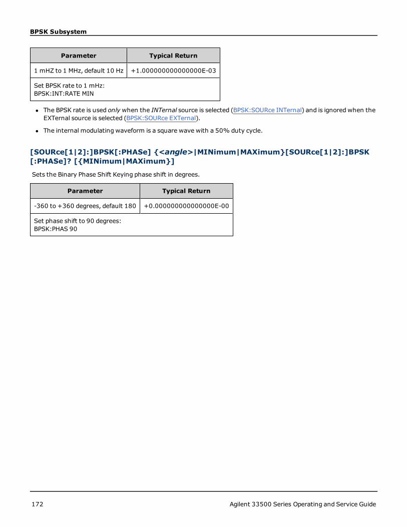
BPSK Subsystem
Parameter Typical Return
1 mHZ to 1 MHz, default 10 Hz +1.000000000000000E-03
Set BPSK rate to 1 mHz:BPSK:INT:RATE MIN
l The BPSK rate is used onlywhen the INTernal source is selected (BPSK:SOURce INTernal) and is ignoredwhen theEXTernal source is selected (BPSK:SOURce EXTernal).
l The internal modulating waveform is a square wave with a 50% duty cycle.
[SOURce[1|2]:]BPSK[:PHASe] {<angle>|MINimum|MAXimum}[SOURce[1|2]:]BPSK[:PHASe]? [{MINimum|MAXimum}]
Sets the Binary Phase Shift Keying phase shift in degrees.
Parameter Typical Return
-360 to +360 degrees, default 180 +0.000000000000000E-00
Set phase shift to 90 degrees:BPSK:PHAS 90
172 Agilent 33500 Series Operating and Service Guide

[SOURce[1|2]:]AM:SOURce {INTernal|EXTernal|CH1|CH2}[SOURce[1|2]:]AM:SOURce?[SOURce
[SOURce[1|2]:]AM:SOURce {INTernal|EXTernal|CH1|CH2}[SOURce[1|2]:]AM:SOURce?
[SOURce[1|2]:]BPSK:SOURce {INTernal|EXTernal}[SOURce[1|2]:]BPSK:SOURce
[SOURce[1|2]:]FM:SOURce {INTernal|EXTernal|CH1|CH2}[SOURce[1|2]:]FM:SOURce
[SOURce[1|2]:]FSKey:SOURce {INTernal|EXTernal}[SOURce[1|2]:]FSKey:SOURce
[SOURce[1|2]:]PM:SOURce {INTernal|EXTernal|CH1|CH2}[SOURce[1|2]:]PM:SOURce
[SOURce[1|2]:]PWM:SOURce {INTernal|EXTernal|CH1|CH2}[SOURce[1|2]:]PWM:SOURce?Select the source of the modulating signal.
Parameter Typical Return
{INTernal|EXTernal|CH1|CH2}, default INTernal. BPSK and FSKey can-not accept CH1 or CH2
INT, EXT, CH1, or CH2
Select external modulation source:AM:SOUR EXT (could also substitute FM, BPSK, FSK, PM, or PWM for AM)
Remarks
l If you select EXTernal, the carrier waveform is modulated with an external waveform. Specifically:
l AM:The modulation depth is controlled by the ±5 V signal level on the rear-panelModulation In connector.For example, if modulation depth (AM[:DEPTh]) is 100%, then when the modulating signal is at +5 V, the out-put will be at the maximum amplitude. Similarly, a -5 Vmodulating signal produces output at minimum ampli-tude.
l FM:If you select the Externalmodulating source, the deviation is controlled by the ±5 V signal level on therear-panelModulation In connector.For example, if the frequency deviation is 100 kHz, then a +5 V signallevel corresponds to a 100 kHz increase in frequency.Lower external signal levels produce less deviation andnegative signal levels reduce the frequency below the carrier frequency.
l PM:With the External modulating source, deviation is controlled by the ±5 V signal level on the rear-panelModulation In connector. For example, if you have set the frequency deviation to 180 degrees, then a +5 Vsignal level corresponds to a +180 degree phase deviation. Lower external signal levels produce less deviation,and negative signal levels produce negative deviation.
Agilent 33500 Series Operating and Service Guide 173

[SOURce[1|2]:]AM:SOURce {INTernal|EXTernal|CH1|CH2}[SOURce[1|2]:]AM:SOURce?[SOURce
l Pulse as Selected Function: The pulse width or pulse duty cycle deviation is controlled by the ±5 V signallevel present on the rear-panelModulation In connector. For example, if you have set the pulse width devi-ation to 50 μs using the PWM:DEViation command, then a +5 V signal level corresponds to a 50 μs widthincrease. Lower external signal levels produce less deviation.
l With EXTernal source, the output phase (BPSK) or frequency (FSK) is determined by the signal level on the rear-panel Ext Trig connector. When a logic low is present, the carrier phase or carrier frequency is output. When alogic high is present, the phase shifted phase or hop frequency is output.
l The maximum external BPSK rate is 1 MHz, and the maximum FSK rate is 1 MHz.
l Note: the connector used for externally-controlled BPSK or FSK waveforms (Trig In) is not the same connectorthat is used for externally-modulated AM, FM, PM, and PWMwaveforms (Modulation In). When used for BPSK orFSK, the Trig In connector does not have adjustable edge polarity and is not affected by the TRIGger[1|2]:SLOPecommand.
l With INTernal source, the rate at which output phase (BPSK) or frequency (FSKey) "shifts" between the carrierphase or frequency and the alternate phase or frequency is determined by the BPSK rate (BPSK:INTernal:RATE) orFSK rate (FSKey:INTernal:RATE).
l A channel may not be its own modulation source.
See Also
AM Subsystem
BPSK Subsystem
FM Subsystem
FSKey Subsystem
PM Subsystem
PWM Subsystem
174 Agilent 33500 Series Operating and Service Guide

[SOURce[1|2]:]AM:STATe {ON|1|OFF|0}[SOURce[1|2]:]AM:STATe?[SOURce[1|2]:]BPSK:STATe
[SOURce[1|2]:]AM:STATe {ON|1|OFF|0}[SOURce[1|2]:]AM:STATe?
[SOURce[1|2]:]BPSK:STATe {ON|1|OFF|0}[SOURce[1|2]:]BPSK:STATe
[SOURce[1|2]:]FM:STATe {ON|1|OFF|0}[SOURce[1|2]:]FM:STATe
[SOURce[1|2]:]FSKey:STATe {ON|1|OFF|0}[SOURce[1|2]:]FSKey:STATe
[SOURce[1|2]:]PM:STATe {ON|1|OFF|0}[SOURce[1|2]:]PM:STATe
[SOURce[1|2]:]PWM:STATe {ON|1|OFF|0}[SOURce[1|2]:]PWM:STATe?Enables or disables modulation.
Parameter Typical Return
{ON|1|OFF|0}, default OFF 0 (OFF) or 1 (ON)
Enable AM (could also substitute FM, BPSK, FSK, PM, or PWM):AM:STAT ON
l To avoidmultiple waveform changes, enable modulation after configuring the other modulation parameters.
l Only one modulation modemay be enabled at a time.
l The instrument will not enable modulation with sweep or burst enabled. When you enable modulation, the sweepor burst mode is turned off.
l PWM is allowed only when pulse is the selected function.
See Also
AM Subsystem
BPSK Subsystem
FM Subsystem
FSKey Subsystem
PM Subsystem
PWM Subsystem
Agilent 33500 Series Operating and Service Guide 175

BURSt Subsystem
BURSt SubsystemThis section describes the BURSt subsystem.
Example
This summarizes the steps required to generate a burst.
1. Configure the burst waveform: Use APPLy or the equivalent FUNCtion, FREQuency, VOLTage, and VOLT-age:OFFSet commands to select the waveform's function, frequency, amplitude, and offset. You can select a sine,square, triangle, ramp, pulse, PRBS, or arbitrary waveform (noise is allowed only in the gated burst mode and DC isnot allowed). For internally-triggered bursts, the minimum frequency is 2.001 mHz. For sine and square wave-forms, frequencies above 6 MHz are allowed only with an "infinite" burst count.
2. Select the "triggered" or "gated" burst mode: Select the triggered burst mode (called "N Cycle" on the frontpanel) or external gated burst mode using BURSt:MODE. If you are using gatedmode, specify true-high or true-low logic with BURSt:GATE:POLarity.
3. Set the burst count: Set the burst count (number of cycles per burst) to any value between 1 and 100,000,000cycles (or infinite) using the BURSt:NCYCles command. Used in the triggered burst mode only. In PRBS,BURSt:NCYCles sets the number of bits of PRBS. Each burst starts at the sequence start.
4. Set the burst period: Set the burst period (the interval at which internally-triggered bursts are generated) toany value from 1 μs to 8000 seconds using BURSt:INTernal:PERiod. Used only in the triggered burst mode with aninternal trigger source.
5. Set the burst starting phase: Set the starting phase of the burst from -360 to +360 degrees usingBURSt:PHASe.
6. Select the trigger source: Select the trigger source using the TRIGger[1|2]:SOURce command. Used in the trig-gered burst mode only.
7. Enable the burst mode: After configuring the other burst parameters, enable the burst mode (BURSt:STATeON).
The following code produces the oscilloscope image shown below.
APPLy:SIN 1e5,3 VPP,0
BURS:MODE TRIG
BURS:NCYC 3
BURS:INT:PER 4.4e-5
BURS:PHAS 0
TRIG:SOUR IMM
BURS:STAT ON
OUTP 1
176 Agilent 33500 Series Operating and Service Guide

BURSt Subsystem
Burst Modes
There are two burst modes, described below. The instrument enables one burst mode at a time.
l Triggered Burst Mode (default): The instrument outputs a waveform for a number of cycles (burst count)each time a trigger is received. After outputting the specified number of cycles, the instrument stops andwaits forthe next trigger. You can configure the instrument to use an internal trigger to initiate the burst or you can pro-vide an external trigger by pressing the front-panel [Trigger] key, by applying a trigger signal to the rear-panelExt Trig connector, or by sending a software trigger command from the remote interface.
l External Gated Burst Mode: The instrument output is either "on" or "off" based on the level of the external sig-nal applied to the rear-panel Ext Trig connector. When this signal is true, the instrument outputs a continuouswaveform.When this signal goes false, the current waveform cycle is completed and then the instrument stopswhile remaining at the voltage corresponding to the starting burst phase of the waveform.
The following table shows which modes are associated with which burst features.
Burst ModeBURSt:MODE
Burst CountBURSt:NCYCles
Burst PeriodBURSt:INTernal:PERiod
Burst PhaseBURSt:PHASe
Trigger SourceTRIGger[1|2]:SOURce
Triggered BurstMode:Internal Trigger
TRIGgered Available Available Available IMMediate
Triggered BurstMode:External Trigger
TRIGgered Available Not Used Available EXTernal, BUS
Gated BurstMode:External Trigger
GATed Not Used Not Used Available Not Used
The difference between gated burst and gated output is that gated burst synchronously starts and stops using full wave-form cycles, where gated output asynchronously turns instrument output on or off with an external trigger, inde-pendent of the waveform phase.
Agilent 33500 Series Operating and Service Guide 177

BURSt Subsystem
[SOURce[1|2]:]BURSt:GATE:POLarity {NORMal|INVerted}[SOURce[1|2]:]BURSt:GATE:POLarity?
Selects true-high (NORMal) or true-low (INVerted) logic levels on the rear-panel Trig In connector for an externallygated burst.
Parameter Typical Return
{NORMal|INVerted}, default NORMal NORM or INV
Select true-low logic for an externally gated burst:BURS:GATE:POL INV
[SOURce[1|2]:]BURSt:INTernal:PERiod {<seconds>|MINimum|MAXimum}[SOURce[1|2]:]BURSt:INTernal:PERiod? [{MINimum|MAXimum}]
Sets the burst period for internally-triggered bursts.
Parameter Typical Return
1 µs to 8000 s, default 10 ms +1.200000000000000E+01
Sets the burst period to 12 seconds:BURS:INT:PER 12
l The burst period is the time between the starts of consecutive bursts.
l This is used only when IMMediate triggering is enabled (TRIGger[1|2]:SOURce IMMediate). It is ignoredwhen man-ual or external triggering is enabled (or with gated burst mode).
l Burst periodmust satisfy the formula below. If the burst period is too short, the instrument will increase it asneeded to continuously re-trigger the burst.From the remote interface, a "Settings conflict" error will also be gen-erated.
Burst Period > (Burst Count /Waveform Frequency) + 200 ns
[SOURce[1|2]:]BURSt:MODE {TRIGgered|GATed}[SOURce[1|2]:]BURSt:MODE?
Selects the burst mode.
Parameter Typical Return
{TRIGgered|GATed}, default TRIGgered TRIG or GAT
Set gated burst modeBURS:MODE GATED
l TRIGgered: the instrument outputs a waveform for a number of cycles (burst count) each time a trigger isreceived from the trigger source (TRIGger[1|2]:SOURce).
178 Agilent 33500 Series Operating and Service Guide

BURSt Subsystem
l In GATed burst mode, the output waveform is on or off, based on the signal at the rear-panel Ext Trig connector.Select this signal's polarity using BURSt:GATE:POLarity. When the gate signal is true, the instrument outputs acontinuous waveform.When the gate signal goes false, the current waveform cycle is completed and the instru-ment stops and remains at the voltage level corresponding to the waveform's starting burst phase. For a noisewaveform, the output stops immediately when the gate signal goes false.
l GATed: burst count, burst period, and trigger source are ignored (these are used for the triggered burst modeonly). If a manual trigger is received (TRIGger[1|2] ), it is ignored and no error will be generated.
[SOURce[1|2]:]BURSt:NCYCles {<num_cycles>|INFinity|MINimum|MAXimum}[SOURce[1|2]:]BURSt:NCYCles? [{MINimum|MAXimum}]
Sets the number of cycles to be output per burst (triggered burst mode only).
Parameter Typical Return
Whole number from 1 (default) to 100,000,000, limited as described below +5.000000000000000E+01
Return number of cycles per burst:BURS:NCYC 50
l With TRIGger[1|2]:SOURce IMMediate, burst count must be less than the product of the maximum burst period(8000 s) and the waveform frequency, as shown below.
Burst Count < (Maximum Burst Period)(Waveform Frequency)
l The increase the burst period up to its maximum value to accommodate the burst count (but the waveformfrequency will not be changed). From the remote interface, a "Settings conflict" error will also be generated.
l When gated burst mode is selected, the burst count is ignored. However, if you change the burst count while inthe gatedmode, the instrument remembers the new count and used it when the triggeredmode is selected.
[SOURce[1|2]:]BURSt:PHASe {<angle>|MINimum|MAXimum}[SOURce[1|2]:]BURSt:PHASe? [{MINimum|MAXimum}]
Sets the starting phase angle for the burst.
Parameter Typical Return
-360 to +360 degrees, or -2π to +2π radians, as specified by UNIT:ANGLe. Default 0. +6.0000000000000E+01
Set starting burst phase to 60 degrees:UNIT:ANGLE DEGBURS:PHAS 60
l Note that BURSt:PHASe is used instead of output phase, andwhen burst is enabled, the output phase is set to 0.
l For sine, square, and ramp, 0 degrees is the point at which the waveform crosses 0 V (or DC offset) in a positive-going direction. For arbitrary waveforms, 0 degrees is the first waveform point. Start phase has no effect on noise.
l For arbitrary waveforms, BURSt:PHASe is only available if the waveform is 1,000,000 points or less.
l Start phase also used in gated burst mode.When the gate signal goes false, the current waveform cycle finishes,and output remains at the voltage level of the starting burst phase.
Agilent 33500 Series Operating and Service Guide 179

BURSt Subsystem
[SOURce[1|2]:]BURSt:STATe {ON|1|OFF|0}[SOURce[1|2]:]BURSt:STATe?
Enables or disables burst mode.
Parameter Typical Return
{ON|1|OFF|0}, default OFF 0 (OFF) or 1 (ON)
Enable burst mode:BURS:STAT ON
l Output phase is set to 0 when burst is enabled.
l To avoidmultiple waveform changes, enable the burst mode after configuring the other burst parameters.
l The instrument will not allow the burst mode to be enabled at the same time that sweep or any modulation modeis enabled. When you enable burst, the sweep or modulation mode is turned off.
180 Agilent 33500 Series Operating and Service Guide

CALibration Subsystem
CALibration SubsystemThe CALibration subsystem is used to calibrate the instrument.
Commands and Queries
CALibration[:ALL]?
CALibration:COUNt?
CALibration:SECure:CODE <new_code>
CALibration:SECure:STATe {OFF | ON} [,<code>]
CALibration:SECure:STATe?
CALibration:SETup<step>
CALibration:SETup?
CALibration:STORe
CALibration:STRing "<string>"
CALibration:STRing?
CALibration:VALue
CALibration:VALue?
CALibration[:ALL]?
Performs a calibration using the calibration value (CALibration:VALue). The instrument must be unlocked (CAL-ibration_SECure_STATe OFF,<code>) to calibrate.
Parameter Typical Return
(none) +0 (pass) or +1 (fail)
Calibrate using the current value:CAL?
l CALibration:SETup should always precede the CALibration? query.
l Increments the instrument’s calibration count (CALibration:COUNt?).
l Modifies the volatile version of the calibration constants. Use CALibration:STORe to save these constants in non-volatile memory at end of calibration.
CALibration:COUNt?
Returns the number of calibrations performed. Read and record the initial count when you receive your instrumentfrom the factory.
Parameter Typical Return
(none) +117
Agilent 33500 Series Operating and Service Guide 181

CALibration Subsystem
Parameter Typical Return
Return the calibration count:CAL:COUN?
l Because the value increments for each calibration point (each CALibration:ALL?), a complete calibration addsmany counts.
l Can display count regardless of whether instrument is secured.
l This setting is non-volatile; it will not be changed by power cycling or *RST.
CALibration:SECure:CODE <new_code>
Sets the security code to prevent unauthorized calibrations.
Parameter Typical Return
Unquoted string up to 12 charactersMust start with letter (A-Z)May contain letters, numbers (0-9) and underscores
(none)
Set new security code:CAL:SEC:CODE MY_CODE_272
l When shipped from the factory, the instrument is secured, with the security code set toAT33520A for the33521A and 33522A, or AT33500 for other 33500 Series instruments.
l To change code: unsecure calibration memory with old code, then set new code.
l If you forget the security code, see Unsecure Instrument Without Security Code.
l This setting is non-volatile; it will not be changed by power cycling or *RST.
CALibration:SECure:STATe {ON|1|OFF|0} [,<code>]CALibration:SECure:STATe?
Unsecures or secures the instrument for calibration. To calibrate, you must unsecure the instrument with the code(CALibration:SECure:CODE).
Parameter Typical Return
{ON|1|OFF|0}, default ON<code> is unquoted string up to 12 characters
0 (OFF) or 1 (ON)
Unsecure calibration:CAL:SEC:STAT OFF,MY_CODE_272Secure calibration:CAL:SEC:STAT ON
l The <code> is optional to secure the instrument, but must be correct if provided.
l Front panel and remote interface calibration use same code. If you secure the instrument from one interface, use
182 Agilent 33500 Series Operating and Service Guide

CALibration Subsystem
the same code to unsecure it from the other interface.
l This setting is non-volatile; it will not be changed by power cycling or *RST.
CALibration:SETup <step>CALibration:SETup?
Configures the calibration step (default 1) to be performed. The instrument must be unlocked (CALibration_SECure_STATe OFF,<code>) to calibrate. See Calibration Security for details.
Parameter Typical Return
Whole number, default 1 +16
Prepare for calibration step 5:CAL:SET 5
l This setting is non-volatile; it will not be changed by power cycling or *RST.
CALibration:STORe
Takes calibration constants in volatile memory (CALibration:ALL?), and places them in nonvolatile memory, wherethey will not be changed by power cycle or *RST. Do this at the end of calibration, to avoid losing changes.
Parameter Typical Return
(none) (none)
Store calibration constants into non-volatile memory:CAL:STOR
CALibration:STRing "<string>"CALibration:STRing?
Stores a message of up to 40 characters in calibration memory. Common messages include last calibration date, cal-ibration due date, or contact information for calibration department. The instrument must be unlocked (CALibration_SECure_STATe OFF,<code>) to store this string.
Parameter Typical Return
Quoted string up to 40 charactersMay contain letters, numbers, spaces, and other common char-acters.
"LAST CAL OCT 31 2011, DUE OCT 312012"(If no string stored, returns "")
CAL:STR "FOR CAL HELP, CALL JOE AT EXT 1234"
l May be stored only from remote interface, with instrument unsecured (CALibration:SECure:STATe OFF).
l You can read the message from the front-panel or remote interface, regardless of whether the instrument issecured.
l Storing a calibration message overwrites the previous message.
l This setting is non-volatile; it will not be changed by power cycling or *RST.
Agilent 33500 Series Operating and Service Guide 183

CALibration Subsystem
CALibration:VALue <value>CALibration:VALue?
Specifies the value of the known calibration signal.
Parameter Typical Return
Numeric, default 0.0 +1.72300000E+001
Specify calibration value 0.0237:CAL:VAL 2.37E-2
l This setting is non-volatile; it will not be changed by power cycling or *RST.
184 Agilent 33500 Series Operating and Service Guide

[SOURce[1|2]:]COMBine:FEED {CH1|CH2|NONE}[SOURce[1|2]:]COMBine:FEED?
[SOURce[1|2]:]COMBine:FEED {CH1|CH2|NONE}[SOURce[1|2]:]COMBine:FEED?Enables or disables the combining of both channels' outputs on a two-channel instrument into a single channel con-nector. The "SOURce" keyword (default, SOURce1) specifies the base channel, and<source> specifies the channel tobe combinedwith the base channel.
Parameter Typical Return
{CH1|CH2|NONE}, default NONE CH1, CH2, or NONE
Set the COMBine:FEED source for base Channel 1 to be Channel 2:COMB:FEED CH2
l COMBine:FEED allows digital data from both channels to be added together to create the output signal on the out-put DAC for the base channel.
l Only one channel may operate in COMBine:FEEDmode at a time
l Unlike the Modulation and SUM commands, COMBine:FEED can add twomodulated signals.
l COMBine:FEED can generate quadrature modulated signals from the two channels to be added together into a sin-gle connector.
l To use COMBine:FEED, first configure all parameters on the individual channels.
l The signals to be combinedmay have a fixed phase offset between the channels.
l You can use COMBine:FEED to add noise from a second channel to a modulated signal on the base channel.
l If COMBine:FEED would cause the combined output to exceed either the instrument's output rating or the pro-grammed limits, the instrument will set COMBine:FEED to NONE and report a settings conflict error.
l Signals are combined in digital form.When two signals of significantly different amplitudes are combined, the loweramplitude signal may have reduced resolution proportional to the ratio of the two amplitudes.
l Changing the function amplitude or sum amplitude of the master or combined channel will not change the ampli-tude or offset of any other function or channel. If changing the function amplitude or sum amplitude of the masteror combined channel would result in exceeding either the output rating or the programmed limits, the amplitudevalue will be clipped and a settings conflict error will be reported.
l Changing the channel offset of the master or combined channel will not change the amplitude or offset of anyother function or channel. If changing channel offset of the master or combined channel would result in exceedingeither the output rating or the programmed limits, the amplitude value will be clipped and the instrument willreport a settings conflict error.
l If turning limits on or adjusting programmed limits would result in a limit being lower than a signal maximum orhigher than a signal minimum, the limits will not be turned on or adjusted, and the instrument will report a set-tings conflict error.
Agilent 33500 Series Operating and Service Guide 185

DATA Subsystem
DATA SubsystemThe DATA subsystem manages user-defined arbitrary waveforms:
l DATA:ARBitrary2:FORMat - specifies the order for bytes in a dual arbitrary waveform file (requires optional IQplayer).
l DATA:ARBitrary[1|2] - downloads arbitrary waveform normalized values to waveform memory
l DATA:ARBitrary[1|2]:DAC - downloads arbitrary waveform DAC codes to waveform memory
l DATA:ATTRibute:AVERage? - returns arithmetic average of all data points for an arbitrary waveform or sequence
l DATA:ATTRibute:CFACtor? - returns crest factor of all data points in an arbitrary waveform or sequence
l DATA:ATTRibute:POINts? - returns number of data points for arbitrary waveform or sequence
l DATA:ATTRibute:PTPeak? - returns peak-to-peak value of all data points in an arbitrary waveform or sequence
l DATA:SEQuence - combines previously loaded arbitrary waveforms into a sequence
l DATA:VOLatile:CATalog - returns the contents of volatile waveform memory, including arbitrary waveforms andsequences
l DATA:VOLatile:CLEar - clears volatile waveform memory
l DATA:VOLatile:FREE? - returns number of points available (free) in volatile memory
Examples
The following example uses DATA commands to set up an arbitrary waveform sequence. Note that the longDATA:SEQuence command splits across lines for readability purposes.
Names of the form a## and ar##, such as a09 and ar27, refer to arbitrary waveforms.
# Build a Sequence from internal memory waveforms with binblock
DATA:SEQuence #42734"mybigSeq1",
a01,0,once,highAtStartGoLow,4,ar01,0,once,highAtStartGoLow,20,
a02,0,once,highAtStartGoLow,5,ar02,0,once,highAtStartGoLow,25,
a03,0,once,highAtStartGoLow,6,ar03,0,once,highAtStartGoLow,30,
a04,0,once,highAtStartGoLow,4,ar04,0,once,highAtStartGoLow,35,
a05,0,once,highAtStartGoLow,5,ar05,0,once,highAtStartGoLow,40,
a06,0,once,highAtStartGoLow,6,ar06,0,once,highAtStartGoLow,45,
a07,0,once,highAtStartGoLow,4,ar07,0,once,highAtStartGoLow,50,
a08,0,once,highAtStartGoLow,5,ar08,0,once,highAtStartGoLow,55,
a09,0,once,highAtStartGoLow,6,ar09,0,once,highAtStartGoLow,60,
a10,0,once,highAtStartGoLow,4,ar10,0,once,highAtStartGoLow,65,
a11,0,once,highAtStartGoLow,5,ar11,0,once,highAtStartGoLow,70,
a12,0,once,highAtStartGoLow,6,ar12,0,once,highAtStartGoLow,75,
a13,0,once,highAtStartGoLow,4,ar13,0,once,highAtStartGoLow,80,
a14,0,once,highAtStartGoLow,5,ar14,0,once,highAtStartGoLow,85,
a15,0,once,highAtStartGoLow,6,ar15,0,once,highAtStartGoLow,90,
a16,0,once,highAtStartGoLow,4,ar16,0,once,highAtStartGoLow,95,
a17,0,once,highAtStartGoLow,5,ar17,0,once,highAtStartGoLow,100,
a18,0,once,highAtStartGoLow,6,ar18,0,once,highAtStartGoLow,105,
186 Agilent 33500 Series Operating and Service Guide

DATA Subsystem
a19,0,once,highAtStartGoLow,4,ar19,0,once,highAtStartGoLow,110,
a20,0,once,highAtStartGoLow,5,ar20,0,once,highAtStartGoLow,115,
a21,0,once,highAtStartGoLow,6,ar21,0,once,highAtStartGoLow,120,
a22,0,once,highAtStartGoLow,4,ar22,0,once,highAtStartGoLow,125,
a23,0,once,highAtStartGoLow,5,ar23,0,once,highAtStartGoLow,130,
a24,0,once,highAtStartGoLow,6,ar24,0,once,highAtStartGoLow,135,
a25,0,once,highAtStartGoLow,4,ar25,0,once,highAtStartGoLow,140,
a26,0,once,highAtStartGoLow,5,ar26,0,once,highAtStartGoLow,145,
a27,0,once,highAtStartGoLow,6,ar27,0,once,highAtStartGoLow,150,
a28,0,once,highAtStartGoLow,4,ar28,0,once,highAtStartGoLow,155,
a29,0,once,highAtStartGoLow,5,ar29,0,once,highAtStartGoLow,160,
a30,0,once,highAtStartGoLow,6,ar30,0,once,highAtStartGoLow,165,
a31,0,once,highAtStartGoLow,4,ar31,0,once,highAtStartGoLow,170,
a32,0,once,highAtStartGoLow,5,ar32,0,once,highAtStartGoLow,175,
a33,0,once,highAtStartGoLow,6,ar33,0,once,highAtStartGoLow,180,
a34,0,once,highAtStartGoLow,4,ar34,0,once,highAtStartGoLow,185,
a35,0,once,highAtStartGoLow,5,ar35,0,once,highAtStartGoLow,190,
a36,0,once,highAtStartGoLow,6,ar36,0,once,highAtStartGoLow,195,
a37,0,once,highAtStartGoLow,4,ar37,0,once,highAtStartGoLow,200,
a38,0,once,highAtStartGoLow,5,ar38,0,once,highAtStartGoLow,205,
a39,0,once,highAtStartGoLow,6,ar39,0,once,highAtStartGoLow,210,
a40,0,once,highAtStartGoLow,4,ar40,0,once,highAtStartGoLow,215,
a41,0,once,highAtStartGoLow,5,ar41,0,once,highAtStartGoLow,220,
a42,0,once,highAtStartGoLow,6,ar42,0,once,highAtStartGoLow,225,
a43,0,once,highAtStartGoLow,4,ar43,0,once,highAtStartGoLow,230,
a01,0,once,highAtStartGoLow,4
FUNCtion:ARB mybigSeq1
MMEMory:STOR:DATA1 "INT:\mybigseq1.seq"
MMEMory:STOR:DATA1 "USB:\mybigseq1.seq"
DATA:VOL:CLEar
MMEMory:LOAD:DATA1 "INT:\mybigseq1.seq"
FUNCtion:ARB "INT:\mybigseq1.seq"
DATA:VOL:CAT?
The code shown below creates the followingwaveform.
FUNC:ARB:SRATE 10E3
FUNC:ARB:FILTER OFF
FUNC:ARB:PTPEAK 10 <--- set the volts peak to peak range
for any downloaded arbitrary waveform or sequence
DATA:ARB dc_ramp, 0.1, 0.1, 0.1, 0.1, 0.1, 0.2, 0.4, 0.6, 0.8, 1.0
DATA:ARB dc5v, 1.0, 1.0, 1.0, 1.0, 1.0, 1.0, 1.0, 1.0, 1.0, 1.0
DATA:ARB dc2_5v, 0.5, 0.5, 0.5, 0.5, 0.5, 0.5, 0.5, 0.5, 0.5, 0.5
DATA:ARB dc0v, 0.0, 0.0, 0.0, 0.0, 0.0, 0.0, 0.0, 0.0, 0.0, 0.0
DATA:SEQuence #3128"seqExample","dc_ramp",0,once,highAtStart,5,"dc5v",
2,repeat,maintain,5,"dc2_v",2,repeat,lowAtStart,5,"dc0v",
Agilent 33500 Series Operating and Service Guide 187

DATA Subsystem
2,repeat,maintain,5
FUNC ARB
FUNC:ARB seqExample
DATA:ATTR:POINTS? <--- result is 40, the sum of four 10-point arbs
DATA:ATTR:PTPEAK? <--- result is 0.5, only using half of 10 Vpp range
OUTPUT ON
Format for <arb_name>
Many DATA commands use the name of an arbitrary waveform. The following rules apply:
l <arb_name>must match:
l A waveform already loaded into waveform memory.
l A waveform existing in INTERNAL or USBmassmemory.
l See MMEMory:LOAD:DATA[1|2], DATA:ARBitrary, or DATA:ARBitrary:DAC for valid formats for <arb_name>.
[SOURce[1|2]:]DATA:ARBitrary2:FORMat {ABAB|AABB}
(Applies only to instruments with the optional IQ player capability.)
Specifies whether the format for data points in DATA:ARB2 and DATA:ARB2:DAC commands is interleaved (ABAB) orall of channel 1 followed by all of channel 2 (AABB).
You may spell out the keyword ARBitrary2, but you must abbreviate it as ARB2. You can-not abbreviate it as ARB.
Parameter Typical Return
{AABB|ABAB} AABB or ABAB
Specify an interleaved data format for dual arbitrary waveform data:
DATA:ARB2:FORM ABAB
188 Agilent 33500 Series Operating and Service Guide

DATA Subsystem
l The SOURce keyword is ignored for this command.
l If you wish to have a 3 DAC count signal on channel 1 and a 4 DAC count signal on channel 2, the AABB formatwould dictate that the data must be sent as 3, 3, 3, 3, 3, 3, 3, 3, 4, 4, 4, 4, 4, 4, 4, 4. The ABAB format would dic-tate the order 3, 4, 3, 4, 3, 4, 3, 4, 3, 4, 3, 4, 3, 4, 3, 4.
[SOURce[1|2]:]DATA:ARBitrary[1|2] <arb_name>, {<binary_block> | <value>,<value>, . . .}
[SOURce[1|2]:]DATA:ARBitrary[1|2]:DAC <arb_name>, {<binary_block> | <value>,<value>, . . .}
Downloads integer values representing DAC codes (DATA:ARBitrary[1|2]:DAC) or floating point values (DATA:ARBitrary[1|2]) into waveform volatile memory as either a list of comma separated values or binary block of data.
The optional [1|2] after the ARBitrary keyword indicates whether the data to be down-loaded contains one (default) or two channels of data.
To use dual arbitrary waveform files (single files containing two channels of arbitrarywaveform data), you must have the optional IQ Player.)
Parameter Typical Return
<arb_name> An unquoted string of up to 12 characters. (none)
<binary_block> integer values from -32767 to +32767 or floatingpoint values from -1.0 to +1.0 in Definite Length Arbitrary Block for-mat (details below). From 8 to 1M or 16M samples per waveform,depending on the model and options.
Definite-length block data allows any type of device-dependent datato be transmitted as a series of 8-bit binary data bytes. This is par-ticularly useful for transferring large quantities of data or 8-bitextended ASCII codes.
<value> comma separated list of integer values from -32,767 to+32,767 or floating point values from -1.0 to +1.0. From 8 to 65,536 points.
Agilent 33500 Series Operating and Service Guide 189

DATA Subsystem
Parameter Typical Return
Download a comma separated list of nine waveform points into waveform memory:DATA:ARB:DACmyArb, 32767, 24576, 16384, 8192, 0, -8192, -16384, -24576, - 32767
Download nine waveform points into waveform memory as a binary block. The <PMT> specifies what terminates thebinary data. It can be a Line Feed character, or the last byte of your_binary_data can assert the End or Identify.DATA:ARBmyArb, #236<36 bytes of your_binary_data><PMT>
Download a comma separated list of nine waveform points into waveform memory:DATA:ARBmyArb, 1, .75, .50, .25, 0, -.25, -.50, -.75, -1
Download eight waveform points of a dual arbitrary waveform into waveform memory as a comma separated list ofDAC codes. There are 16 values in all, eight for each of two channels. Note that the data is interleaved (ABAB), so thepositive values are all on channel 1, and the negative values are all on channel 2:DATA:ARB2:FORM ABABDATA:ARB2:DACmyArb, 30000, -10000, 29000, -9000, 27000, -7000, 24000, -4000, 27000, -7000, 29000, -9000, 30000, -10000, 29000, -9000
Download the same examples as above, but in AABB format:DATA:ARB2:FORM AABBDATA:ARB2:DACmyArb, 30000, 29000, 27000, 24000, 27000, 29000, 30000, 29000, -10000, -9000, -7000,-4000, -7000, -9000, -10000, -9000
l Each data point is either a 16-bit integer from -32,767 and+32,767 or a 32-bit floating point value from -1.0 to+1.0. Therefore, the total number of bytes is always two times or four times the number of data points in thewaveform. For example, 16,000 bytes are required to download a waveform with 8,000 points as integers, but 32,000 bytes are required to download the same waveform as floating point values.
l The values -32767 and+32767 or -1.0 to +1.0 correspond to the peak values of the waveform (if the offset is 0V). For example, if you set the output amplitude to 10 Vpp, +32767 corresponds to +5 V and -32767 correspondsto -5 V.
l Use FORMat:BORDer to select the byte order for block mode binary transfers.
l Use DATA:ARB2:FORMat to specify whether dual arbitrary waveforms are interleaved or sequential (channel 1 fol-lowed by channel 2).
l Specifying a waveform that is already loaded generates a "Specified arb waveform already exists" error. Deletingan existing waveform requires clearing all of the waveform memory with DATA:VOLatile:CLEar.
l Either 1 MSa or 16 MSa (depending on model and options) is the total available sample size for all waveformsloaded per channel. A new waveform may be limited by waveforms already loaded.
[SOURce[1|2]:]DATA:ATTRibute:AVERage? [<arb_name>]
Returns the arithmetic mean of all data points for the specified arbitrary waveform INTERNAL or USB memory, orloaded into waveform memory.
Parameter Typical Return
<arb_name> is any valid file name. If omitted, the default <arb_name> is the arbitrary wave-form currently active (selected with FUNCtion:ARBitrary).
+2.45036000E-002
Return the mean of all points stored in "SINC".DATA:ATTR:AVER?" INT:\BuiltIn\SINC.arb"
190 Agilent 33500 Series Operating and Service Guide

DATA Subsystem
l Querying a waveform that does not exist generates a "Specified arb waveform does not exist" error.
l <arb_name> can be a file name (put in memory by MMEMory:LOAD:DATA[1|2]) or a name generated fromDATA:ARBitrary or DATA:ARBitrary:DAC.
[SOURce[1|2]:]DATA:ATTRibute:CFACtor? [<arb_name>]
Returns the crest factor of all data points for the specified arbitrary waveform segment in INTERNAL or USB memory,or loaded into waveform memory.
Parameter Typical Return
<arb_name> is any valid file name. If omitted, the default <arb_name> is the arbitrarywaveform currently active (selected with FUNCtion:ARBitrary).
+1.73205100E+000
Return crest factor of all data points stored in "NEG_RAMP".DATA:ATTR:CFAC? "INT:\BuiltIn\NEG_RAMP.arb"
l Crest factor is the ratio of the peak value to the RMS value of the waveform.
l Querying a waveform that does not exist generates a "Specified arb waveform does not exist" error.
l <arb_name> can be a file name (put in memory by MMEMory:LOAD:DATA[1|2]) or a name generated fromDATA:ARBitrary or DATA:ARBitrary:DAC.
[SOURce[1|2]:]DATA:ATTRibute:POINts? [<arb_name>]
Returns the number of points in the specified arbitrary waveform segment in INTERNAL or USB memory, or loadedinto waveform memory.
Parameter TypicalReturn
<arb_name> is any valid file name. If omitted, the default <arb_name> is the arbitrary waveformcurrently active (selected with FUNCtion:ARBitrary).
+40
Returns the number of data points in "EXP_RISE":DATA:ATTR:POIN? "INT:\BuiltIn\EXP_RISE.arb"
l <arb_name> can be a file name (put in memory by MMEMory:LOAD:DATA[1|2]) or a name generated fromDATA:ARBitrary or DATA:ARBitrary:DAC.
[SOURce[1|2]:]DATA:ATTRibute:PTPeak? [<arb_name>]
This query calculates the peak-to-peak value of all data points for the specified arbitrary waveform segment in INTER-NAL or USB memory, or loaded into waveform memory.
Parameter Typical Return
Any valid file name. If omitted, the default <arb_name> is the arbitrary waveform currentlyactive (selected with FUNCtion:ARBitrary).
+1.00000000E+00
Return the peak-to-peak value for "EXP_FALL":DATA:ATTR:PTP? "INT:\BuiltIn\EXP_FALL.arb"
Agilent 33500 Series Operating and Service Guide 191

DATA Subsystem
l <arb_name>must match:
l A waveform already loaded into waveform memory.
l A waveform existing in INTERNAL or USBmassmemory.
l See MMEMory:LOAD:DATA[1|2], DATA:ARBitrary, or DATA:ARBitrary:DAC for valid formats for <arb_name>.
l Arbitrary Waveform Limitations: For arbitrary waveforms, amplitude is limited if the waveform data points do notspan the full range of the output DAC (Digital-to-Analog Converter). For example, the built-in "Sinc" waveformdoes not use the full range of values, so its maximum amplitude is limited to 6.087 Vpp (into 50 Ω).
l <arb_name> can be a file name (put in memory by MMEMory:LOAD:DATA[1|2]) or a name generated fromDATA:ARBitrary or DATA:ARBitrary:DAC.
[SOURce[1|2]:]DATA:SEQuence <block_descriptor>
Defines a sequence of waveforms already loaded into waveform memory via MMEMory:LOAD:DATA[1|2] or DATA:A-RBitrary. The MMEMory:LOAD:DATA[1|2] command can also load a sequence file that automatically loads the asso-ciated arbitrary waveforms and includes the amplitude, offset, sample rate, and filter setup.
Parameter Typical Return
IEEE Definite Length Arbitrary Block, described below. (none)
(see example)
l Even arbitrary waveforms with millions of points may be insufficient for applications requiring special sequencingor the repetition of waveforms dependent upon time or external events. Sequencing arbitrary waveforms allowsyou to arrange and conditionally repeat waveforms. This allows you to use less memory and to achieve greaterapplication flexibility.
Definite-length block data allows any type of device-dependent data to be transmitted as a series of 8-bit binary databytes. This is particularly useful for transferring large quantities of data or 8-bit extended ASCII codes.
l <block_descriptor> is of the format #<n><n digits><sequence name>,<arb name1>,<repeat count1>,<playcontrol1>,<marker mode1>, <marker point1>, <arb name2>,<repeat count2>,<play control2>,<markermode2>, <marker point2>, and so on, where:
l <n>specifies the number of digits used to indicate the size of the block.
l <n digits> is one or more digits hat specifies the number of data bytes to come.
l <sequence name> an unquoted ASCII string which specifies the name of sequence that contains the arbitrarywaveforms specified in the following parameters.
l <arb name> a quoted string that specifies the name of the arbitrary waveform that was loadedwith theMMEM:LOAD:DATA[1|2] or DATA:ARBitrary commands.
l <repeat count> specifies the number of times to repeat the waveform. This value can range from 1 to 1E6 orinfinite. This will only be recognized in the hardware if Play Control is set to "repeat"
l <play control> is a quoted string which specifies how the arbitrary waveform is to be played in the sequence.Valid choices are:
l "once"- play once
192 Agilent 33500 Series Operating and Service Guide

DATA Subsystem
l "onceWaitTrig"- play once and then wait for trigger. Triggers will not be accepted until the play of thespecified segment has completed.
l "repeat"- repeat number of times specified by repeat count
l "repeatInf"- repeat until stopped (infinite)
l "repeatTilTrig" - repeat until triggered then advance
l <marker mode> a quoted string which specifies how the marker behaves in the arbitrary waveform. Validchoices are:
l "maintain"-maintain current marker state at start of segment
l "lowAtStart"- force marker low at start of segment
l "highAtStart"- force marker high at start of segment
l "highAtStartGoLow"- force marker high at start of segment and then low at marker position
l <marker point> a number specifying the marker location in the arbitrary waveform. This value must bebetween 4 and the number of points in the arbitrary waveform minus 3.
l If you specify an arbitrary waveform that has not been loaded, a "Specified arb waveform does not exist" error isgenerated.
Example of DATA:SEQuence command
The following command constructs a sequence (namedmySequence) of three segments (A.arb, B.arb, and C.arb) thatwere previously loaded from the USB drive usingMMEMory:LOAD:DATA[1|2]. The sequence plays A once, and B fivetimes. It then plays C repeatedly while waiting for a trigger to advance, and finally ends with A. Each segment has the<marker point> set to 10.
The command is shown on multiple lines for readability purposes only.
DATA:SEQ #3158"mySequence","USB:\A.arb",0,once,lowAtStart,10,"USB:\B.arb",5,repeat,highAtStart,
10,
"USB:\C.arb",0,repeatTilTrig,maintain,10,"USB:\A.arb",0,once,lowAtStart,10
Many text editors let you count the number of bytes in the block simply by highlighting the characters from the "m" inmySequence to the "0" at the end of the line. In this example, the size is 143, which requires 3 digits to represent –hence the #3143 header.
Using this approach requires you to pre-load all of the arbitrary waveforms and set the amplitude and offset (or highand low levels), sample rate, and filter. See MMEM:LOAD:DATA to combine all that information into a single file ratherthan creating a block transfer with multiple SCPI commands.
[SOURce[1|2]:]DATA:VOLatile:CATalog?
Returns the contents of volatile waveform memory, including arbitrary waveforms and sequences.
Parameter Typical Return
(none) "INT:\BUILTIN\EXP_RISE.ARB","USB:\XYZ\A.ARB","USB:\XYZ\B.ARB","USB:\xyz\xyz.seq"
Agilent 33500 Series Operating and Service Guide 193
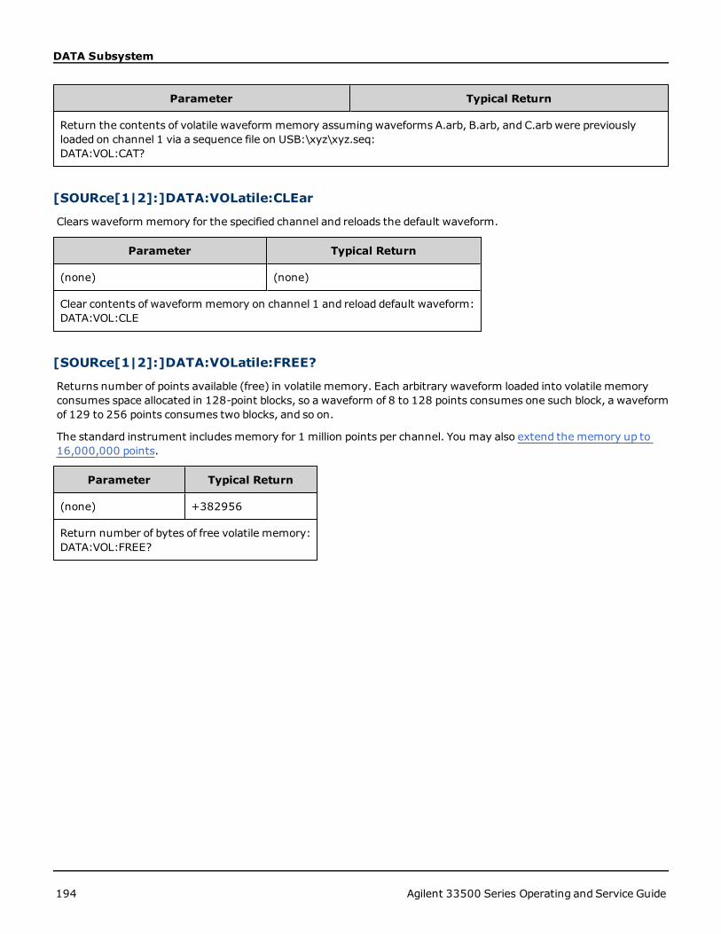
DATA Subsystem
Parameter Typical Return
Return the contents of volatile waveform memory assumingwaveforms A.arb, B.arb, and C.arb were previouslyloaded on channel 1 via a sequence file on USB:\xyz\xyz.seq:DATA:VOL:CAT?
[SOURce[1|2]:]DATA:VOLatile:CLEar
Clears waveform memory for the specified channel and reloads the default waveform.
Parameter Typical Return
(none) (none)
Clear contents of waveform memory on channel 1 and reload default waveform:DATA:VOL:CLE
[SOURce[1|2]:]DATA:VOLatile:FREE?
Returns number of points available (free) in volatile memory. Each arbitrary waveform loaded into volatile memoryconsumes space allocated in 128-point blocks, so a waveform of 8 to 128 points consumes one such block, a waveformof 129 to 256 points consumes two blocks, and so on.
The standard instrument includes memory for 1 million points per channel. You may also extend the memory up to16,000,000 points.
Parameter Typical Return
(none) +382956
Return number of bytes of free volatile memory:DATA:VOL:FREE?
194 Agilent 33500 Series Operating and Service Guide
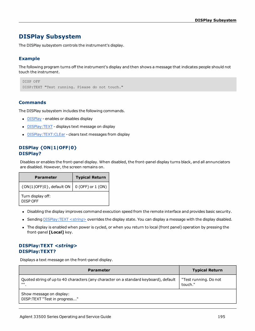
DISPlay Subsystem
DISPlay SubsystemThe DISPlay subsystem controls the instrument's display.
Example
The following program turns off the instrument's display and then shows amessage that indicates people should nottouch the instrument.
DISP OFF
DISP:TEXT "Test running. Please do not touch."
Commands
The DISPlay subsystem includes the following commands.
l DISPlay - enables or disables display
l DISPlay:TEXT - displays text message on display
l DISPlay:TEXT:CLEar - clears text messages from display
DISPlay {ON|1|OFF|0}DISPlay?
Disables or enables the front-panel display. When disabled, the front-panel display turns black, and all annunciatorsare disabled. However, the screen remains on.
Parameter Typical Return
{ON|1|OFF|0}, default ON 0 (OFF) or 1 (ON)
Turn display off:DISP OFF
l Disabling the display improves command execution speed from the remote interface and provides basic security.
l Sending DISPlay:TEXT <string> overrides the display state. You can display a message with the display disabled.
l The display is enabled when power is cycled, or when you return to local (front panel) operation by pressing thefront-panel [Local] key.
DISPlay:TEXT <string>DISPlay:TEXT?
Displays a text message on the front-panel display.
Parameter Typical Return
Quoted string of up to 40 characters (any character on a standard keyboard), default"".
"Test running. Do nottouch."
Show message on display:DISP:TEXT "Test in progress..."
Agilent 33500 Series Operating and Service Guide 195

DISPlay Subsystem
l Sending DISPlay:TEXT <string> overrides the display state. You can display a message with the display disabled.
l While a message is displayed, information relating to the current instrument operation is not sent to the front-panel display.
l The display text is unaffected by *RST. It is cleared at power-on.
DISPlay:TEXT:CLEar
Clears the text message from the front-panel display.
Parameter Typical Return
(none) (none)
Clear message on display:DISP:TEXT:CLE
l With DISPlay ON, DISP:TEXT:CLEar returns the display to its normal mode.
l With DISPlay OFF, DISP:TEXT:CLEar clears the message and the display remains disabled. To enable the display,send DISPplay ON or press the front-panel [Local] key.
l The display text is unaffected by *RST. It is cleared at power-on.
196 Agilent 33500 Series Operating and Service Guide

FM Subsystem
FM SubsystemThis summarizes the steps required to generate a frequency modulation (FM) waveform.
1. Configure carrier waveform: Use FUNCtion, FREQuency, VOLTage, and VOLTage:OFFSet to specify the carrierwaveform's function, frequency, amplitude, and offset.
2. Select modulation source (internal, external, CH1, or CH2):FM:SOURce. For an external modulationsource, skip steps 3 and 4.
3. Select modulating waveform: FM:INTernal:FUNCtion
4. Set modulating frequency: FM:INTernal:FREQuency
5. Set peak frequency deviation: FM:DEViation
6. Enable FM:FM:STATe:ON
The following code produces the oscilloscope image shown below.
FUNCtion SQU
FREQuency +4.0E+05
VOLTage +1.0
VOLTage:OFFset 0.0
FM:SOURce INT
FM:DEViation +3.5e5
FM:INTernal:FREQuency +5e4
FM:INTernal:FUNCtion RAMP
FM:STATe 1
OUTP 1
[SOURce[1|2]:]FM[:DEViation] {<peak_deviation_in_Hz>|MINimum|MAXimum}[SOURce[1|2]:]FM[:DEViation]? [{MINimum|MAXimum}]
Sets the peak frequency deviation in Hz. This value represents the peak variation in frequency of themodulatedwave-form from the carrier frequency.
Agilent 33500 Series Operating and Service Guide 197

FM Subsystem
Parameter Typical Return
1 μHz to 15.05 (limited to 150 kHz for RAMP); default 100 Hz +1.000000000000000E+03
Set peak frequency deviation to 1 kHz:FM:DEV 1000
Set peak frequency deviation to 1 μHz:FM:DEV MIN
l The deviation cannot exceed the carrier frequency. If you attempt to set a deviation that exceeds the carrierfrequency (with FM enabled), the instrument will adjust the deviation to the maximum value allowed for that car-rier frequency. From the remote interface, a "Settings conflict" error will also be generated.
l The carrier frequency plus the deviation cannot exceed the selected function's maximum frequency plus 100 kHz.If you attempt to set the deviation to an invalid value, the instrument adjusts it to the maximum value allowedwith the present carrier frequency. The remote interface also generates a "Data out of range" error.
l If the deviation causes the carrier waveform to exceed a frequency boundary for the current duty cycle (squarewaveform only), the instrument will adjust the duty cycle to the maximum value allowedwith the present carrierfrequency. From the remote interface, a "Settings conflict" error will also be generated.
l If you select the Externalmodulating source, the deviation is controlled by the ±5 V signal level on the rear-panelModulation In connector.For example, if the frequency deviation is 100 kHz, then a +5 V signal level cor-responds to a 100 kHz increase in frequency.Lower external signal levels produce less deviation and negative sig-nal levels reduce the frequency below the carrier frequency.
[SOURce[1|2]:]FM:INTernal:FREQuency {<frequency>|MINimum|MAXimum}[SOURce[1|2]:]FM:INTernal:FREQuency? [{MINimum|MAXimum}]
Sets the frequency of the modulating waveform. The modulating source waveform operates at that frequency, withinthe frequency limits of that waveform.
Parameter Typical Return
1 μHz to the maximum allowed for the internal function. Default 10 Hz +1.000000000000000E+04
Set the modulating frequency to 10 kHz:FM:INT:FREQ 10000
l When you select an arbitrary waveform as the modulating source, the frequency changes to the frequency of thearbitrary waveform, which is based on the sample rate and the number of points in the arbitrary waveform.
l When using an arbitrary waveform for the modulating source, changing this parameter also changes the cachedmetadata representing the aribtrary waveform's sample rate. You can also change the modulating frequency of anarbitrary waveform with FUNCtion:ARBitrary:FREQuency, FUNCtion:ARBitrary:PERiod, and FUNC-tion:ARBitrary:SRATe. These commands and the modulation frequency command are directly coupled in order tokeep the arbitrary waveform behaving exactly as it was last played. If you later turn modulation off and select thatsame arbitrary waveform as the current function, its sample rate (and corresponding frequency based upon thenumber of points) will be the same as it was when played as the modulation source.
l If the internal function is TRIangle, UpRamp, or DnRamp, the maximum frequency limited to 200 kHz. If the inter-nal function is PRBS, the frequency refers to bit rate and is limited to 50 Mbps.
l This command should be used only with the internal modulation source (FM:SOURce INTernal).
198 Agilent 33500 Series Operating and Service Guide

FM Subsystem
[SOURce[1|2]:]FM:INTernal:FUNCtion <function>[SOURce[1|2]:]FM:INTernal:FUNCtion?
This command selects the shape of the modulating waveform.
Parameter Typical Return
{SINusoid|SQUare|RAMP|NRAMp|TRIangle|NOISe|PRBS|ARB},default SINusoidView internal function waveforms.
SIN, SQU, RAMP, NRAM, TRI, NOIS, PRBS,or ARB
Select a sine wave as the modulating waveform.FM:INT:FUNC SIN
l This command should be used only with the internal modulation source (FM:SOURce INTernal).
l Some combinations of carrier and internal function are not allowed: PRBS carrier and PRBS internal function, ARBcarrier and ARB internal function.
l You can use noise as the modulating waveform, but you cannot use noise, pulse, or DC as the carrier.
Agilent 33500 Series Operating and Service Guide 199

[SOURce[1|2]:]AM:SOURce {INTernal|EXTernal|CH1|CH2}[SOURce[1|2]:]AM:SOURce?[SOURce
[SOURce[1|2]:]AM:SOURce {INTernal|EXTernal|CH1|CH2}[SOURce[1|2]:]AM:SOURce?
[SOURce[1|2]:]BPSK:SOURce {INTernal|EXTernal}[SOURce[1|2]:]BPSK:SOURce
[SOURce[1|2]:]FM:SOURce {INTernal|EXTernal|CH1|CH2}[SOURce[1|2]:]FM:SOURce
[SOURce[1|2]:]FSKey:SOURce {INTernal|EXTernal}[SOURce[1|2]:]FSKey:SOURce
[SOURce[1|2]:]PM:SOURce {INTernal|EXTernal|CH1|CH2}[SOURce[1|2]:]PM:SOURce
[SOURce[1|2]:]PWM:SOURce {INTernal|EXTernal|CH1|CH2}[SOURce[1|2]:]PWM:SOURce?Select the source of the modulating signal.
Parameter Typical Return
{INTernal|EXTernal|CH1|CH2}, default INTernal. BPSK and FSKey can-not accept CH1 or CH2
INT, EXT, CH1, or CH2
Select external modulation source:AM:SOUR EXT (could also substitute FM, BPSK, FSK, PM, or PWM for AM)
Remarks
l If you select EXTernal, the carrier waveform is modulated with an external waveform. Specifically:
l AM:The modulation depth is controlled by the ±5 V signal level on the rear-panelModulation In connector.For example, if modulation depth (AM[:DEPTh]) is 100%, then when the modulating signal is at +5 V, the out-put will be at the maximum amplitude. Similarly, a -5 Vmodulating signal produces output at minimum ampli-tude.
l FM:If you select the Externalmodulating source, the deviation is controlled by the ±5 V signal level on therear-panelModulation In connector.For example, if the frequency deviation is 100 kHz, then a +5 V signallevel corresponds to a 100 kHz increase in frequency.Lower external signal levels produce less deviation andnegative signal levels reduce the frequency below the carrier frequency.
l PM:With the External modulating source, deviation is controlled by the ±5 V signal level on the rear-panelModulation In connector. For example, if you have set the frequency deviation to 180 degrees, then a +5 Vsignal level corresponds to a +180 degree phase deviation. Lower external signal levels produce less deviation,and negative signal levels produce negative deviation.
200 Agilent 33500 Series Operating and Service Guide

[SOURce[1|2]:]AM:SOURce {INTernal|EXTernal|CH1|CH2}[SOURce[1|2]:]AM:SOURce?[SOURce
l Pulse as Selected Function: The pulse width or pulse duty cycle deviation is controlled by the ±5 V signallevel present on the rear-panelModulation In connector. For example, if you have set the pulse width devi-ation to 50 μs using the PWM:DEViation command, then a +5 V signal level corresponds to a 50 μs widthincrease. Lower external signal levels produce less deviation.
l With EXTernal source, the output phase (BPSK) or frequency (FSK) is determined by the signal level on the rear-panel Ext Trig connector. When a logic low is present, the carrier phase or carrier frequency is output. When alogic high is present, the phase shifted phase or hop frequency is output.
l The maximum external BPSK rate is 1 MHz, and the maximum FSK rate is 1 MHz.
l Note: the connector used for externally-controlled BPSK or FSK waveforms (Trig In) is not the same connectorthat is used for externally-modulated AM, FM, PM, and PWMwaveforms (Modulation In). When used for BPSK orFSK, the Trig In connector does not have adjustable edge polarity and is not affected by the TRIGger[1|2]:SLOPecommand.
l With INTernal source, the rate at which output phase (BPSK) or frequency (FSKey) "shifts" between the carrierphase or frequency and the alternate phase or frequency is determined by the BPSK rate (BPSK:INTernal:RATE) orFSK rate (FSKey:INTernal:RATE).
l A channel may not be its own modulation source.
See Also
AM Subsystem
BPSK Subsystem
FM Subsystem
FSKey Subsystem
PM Subsystem
PWM Subsystem
Agilent 33500 Series Operating and Service Guide 201

[SOURce[1|2]:]AM:STATe {ON|1|OFF|0}[SOURce[1|2]:]AM:STATe?[SOURce[1|2]:]BPSK:STATe
[SOURce[1|2]:]AM:STATe {ON|1|OFF|0}[SOURce[1|2]:]AM:STATe?
[SOURce[1|2]:]BPSK:STATe {ON|1|OFF|0}[SOURce[1|2]:]BPSK:STATe
[SOURce[1|2]:]FM:STATe {ON|1|OFF|0}[SOURce[1|2]:]FM:STATe
[SOURce[1|2]:]FSKey:STATe {ON|1|OFF|0}[SOURce[1|2]:]FSKey:STATe
[SOURce[1|2]:]PM:STATe {ON|1|OFF|0}[SOURce[1|2]:]PM:STATe
[SOURce[1|2]:]PWM:STATe {ON|1|OFF|0}[SOURce[1|2]:]PWM:STATe?Enables or disables modulation.
Parameter Typical Return
{ON|1|OFF|0}, default OFF 0 (OFF) or 1 (ON)
Enable AM (could also substitute FM, BPSK, FSK, PM, or PWM):AM:STAT ON
l To avoidmultiple waveform changes, enable modulation after configuring the other modulation parameters.
l Only one modulation modemay be enabled at a time.
l The instrument will not enable modulation with sweep or burst enabled. When you enable modulation, the sweepor burst mode is turned off.
l PWM is allowed only when pulse is the selected function.
See Also
AM Subsystem
BPSK Subsystem
FM Subsystem
FSKey Subsystem
PM Subsystem
PWM Subsystem
202 Agilent 33500 Series Operating and Service Guide

FORMat:BORDer {NORMal|SWAPped}FORMat:BORDer?
FORMat:BORDer {NORMal|SWAPped}FORMat:BORDer?Sets the byte order used in binary data point transfers in the block mode.
Parameter Typical Return
{NORMal|SWAPped}, default NORMal NORM or SWAP
Set SWAPped order:FORM:BORD SWAP
l NORMal:most-significant byte (MSB) of each data point is first.
l SWAPped: least-significant byte (LSB) of each data point is first. Most computers use this.
Agilent 33500 Series Operating and Service Guide 203

204 Agilent 33500 Series Operating and Service Guide

FREQuency Subsystem
FREQuency SubsystemThe FREQuency subsystem sets the instrument's output frequency. In two-channel instruments, the channels'frequencies may be coupled in various ways.
FREQuency:COUPle[:STATe] {ON|OFF|ONCE} enables or disables coupling, or using the ONCE, one channel's iscopied to the other, but not coupled to it.
FREQuency:COUPle:MODE {OFFSet|RATio} specifies the frequency couplingmode.
FREQuency:MODE allows you to specify a frequency mode to use, including a sweep, frequency list, or fixedfrequency.
Example
The remaining FREQuency commands are used to generate a sweep, as summarized below:
1. Select the waveform shape, amplitude and offset: Use APPLy or the equivalent FUNCtion, FREQuency,VOLTage, and VOLTage:OFFSet commands to select the function, frequency, amplitude, and offset. You can selectany non-arbitrary waveform.
2. Set frequency boundaries of the sweep:FREQuency:STARt and FREQuency:STOP, or FREQuency:CENTerand FREQuency:SPAN.
3. Select sweep mode (linear or logarithmic): SWEep:SPACing
4. Set sweep time in seconds: SWEep:TIME
5. Select sweep trigger source: TRIGger[1|2]:SOURce
6. Set frequency at which signal on front-panel Sync connector goes low during sweep(optional):MARKer:FREQuency
[SOURce[1|2]:]FREQuency {<frequency>|MINimum|MAXimum}[SOURce[1|2]:]FREQuency? [{MINimum|MAXimum}]
Sets the output frequency. This command is paired with FUNCtion:PULSe:PERiod; whichever one is executed last over-rides the other.
Parameter Typical Return
1 μHz tomaximum instrument frequency, except for triangle and ramp, which arelimited to 200 kHz. Default 1 kHz
+1.000000000000000E+03
Set output frequency to 60 Hz:FREQ 60
l Function Limitations: The frequency limits are function dependent, as shown in the above table. If you send a com-mand specifying a frequency that is not in the appropriate range for the current function, an error will occur. Forexample, if the current function is "ramp" and you send the command FREQ 20 MHZ, a "Data out of range" error isgenerated and the frequency is set to 200 kHz, which is the maximum for a rampwaveform.
[SOURce[1|2]:]FREQuency:CENTer {<frequency>|MINimum|MAXimum}[SOURce[1|2]:]FREQuency:CENTer? [{MINimum|MAXimum}]
Sets the center frequency. Usedwith frequency span for a frequency sweep.
Agilent 33500 Series Operating and Service Guide 205

FREQuency Subsystem
Parameter Typical Return
1 μHz tomaximum instrument frequency, except for triangle and ramp, which arelimited to 200 kHz. Default default 550 Hz
+1.000000000000000E+03
Set sweep center frequency to 1 kHz:FREQ:CENT 1000
l The following equation shows how center frequency is limited by span frequency.
Center Frequency (max) = Max. Frequency for waveform - (Span/2)
l The following equation shows how center frequency relates to start and stop frequencies.
Center Frequency = |(Stop Frequency - Start Frequency)|/2
[SOURce[1|2]:]FREQuency:COUPle[:STATe] {ON|1|OFF|0}[SOURce[1|2]:]FREQuency:COUPle[:STATe]?
Enables/disables frequency coupling between channels in a two-channel instrument.
Parameter Typical Return
{ON|1|OFF|0}, default OFF 0 (OFF) or 1 (ON)
Turn on the frequency couple state:FREQ:COUP ON
l Specifying ON starts frequency coupling as specified by FREQuency:COUPle:MODE.
l If the current offset or ratio, combinedwith the current frequency settings, would cause either frequency toexceed instrument specifications, the instrument will generate an error and the exceeded frequency will clip at itsmaximum or minimum value.
l If settingmode to RATIO and setting RATIO to 1.0 still exceeds the specifications of either channel (for example,channel 1 is a 3 MHz sine and channel 2 is a ramp, which cannot go that high), an error message will be generatedand FREQuency:COUPle will be turned OFF.
[SOURce[1|2]:]FREQuency:COUPle:MODE {OFFSet|RATio}[SOURce[1|2]:]FREQuency:COUPle:MODE?
Sets the type of frequency coupling between frequency coupled channels; OFFSet specifies a constant frequency offsetbetween channels; RATio specifies a constant ratio between the channels' frequencies.
Parameter Typical Return
{OFFSet|RATio}, default RATio with ratio 1.0 OFFS or RAT
Set frequency couplingmode to OFFSet:FREQ:COUP:MODE OFFS
l Power-on default for frequency coupling is OFF.
l Specifying SOURce1 or SOURce2 is irrelevant; either syntax sets the same couplingmode for both channels.
206 Agilent 33500 Series Operating and Service Guide

FREQuency Subsystem
[SOURce[1|2]:]FREQuency:COUPle:OFFSet <frequency>[SOURce[1|2]:]FREQuency:COUPle:OFFSet?
Sets the offset frequency when an instrument is in frequency coupledmode OFFSet.
Parameter Typical Return
A number between plus andminus the instrument's maximum frequency (limitedto ± 200 kHz for ramps and triangles); default 0.
+7.650000000000000E+05
Set frequency of channel 2 to 10.245 MHz above frequency of channel 1:FREQ:COUP:OFFS 10.245 MHZ
Set frequency of channel 1 to 350 kHz above frequency of channel 2:SOUR2:FREQ:COUP:OFFS 350 KHZ
Set frequency of channel 1 to 455 kHz below frequency of channel 2:SOUR2:FREQ:COUP:OFFS -455 KHZ
l The SOURce channel (SOURce1 or SOURce2) is used as the reference channel and the OFFSet is applied to the otherchannel. For example, suppose the instrument is in FREQ:COUPLE:STATE ON and in FREQ:COUPLE:MODE OFFSET(frequency offset mode active), and channel 1 is currently operating at 1.0 MHz. The command SOURce1:FREQu-ency:COUPle:OFFSet 500 will cause channel 1 to remain at 1.0 MHz, and channel 2 to be set to 1.5 MHz. As thefrequency of either channel is changed, the frequency of the other channel will change tomaintain the 500 kHz offset.
l If the frequency coupling would cause either channel to exceed instrument frequency specifications for thepresent functions, the commandwill result in an error, and the frequency will be set to its maximum or minimumlimit for that channel.
l Frequency coupling is not valid with arbitrary waveforms, but you can couple the sample rate of arbitrary wave-forms.
[SOURce[1|2]:]FREQuency:COUPle:RATio <ratio>[SOURce[1|2]:]FREQuency:COUPle:RATio?
Sets offset ratio between channel frequencies in frequency coupledmode RATio.
Parameter Typical Return
0.001 to 1000, default 1 +7.500000000000000E-01
Set frequency of channel 2 to twice the frequency of channel 1:FREQ:COUP:RAT 2.0
Set frequency of channel 1 to 3.14 times the frequency of channel 2:SOUR2:FREQ:COUP:RAT 3.14
l The SOURce channel (SOURce1 or SOURce2) is used as the reference channel and the RATIO is applied to theother channel. For example, suppose the instrument is in FREQuency:COUPle ON and FREQuency:COUPle:MODERATio. Furthermore, suppose channel 1 is currently operating at 2 kHz, and channel 2 is at 10 kHz. The commandSOURce1:FREQuency:COUPle:RATio 2.5 will cause channel 1 to remain at 2 kHz, and Channel 2 to be set to 5 kHz.As the frequency of either channel is changed, the frequency of the other channel will change tomaintain the 2.5ratio.
Agilent 33500 Series Operating and Service Guide 207

FREQuency Subsystem
l If the frequency coupling would cause either channel to exceed instrument frequency specifications for thepresent functions, the commandwill result in an error, and the frequency will be set to its maximum or minimumlimit for that channel.
l Frequency coupling is not valid with arbitrary waveforms, but you can couple the sample rate of arbitrary wave-forms.
[SOURce[1|2]:]FREQuency:MODE {CW|LIST|SWEep|FIXed}[SOURce[1|2]:]FREQuency:MODE?
Sets the type of frequency mode as a continuous wave at a fixed frequency (CW or FIXed), a frequency sweep(SWEep), or a frequency list (LIST).
Parameter Typical Return
{CW|LIST|SWEep|FIXed}, default CW CW, LIST, SWE, or FIX
Set frequency mode to LIST:FREQ:MODE LIST
l If the mode is set to list, use LIST:FREQuency to specify the frequency list.
[SOURce[1|2]:]FREQuency:SPAN {<frequency>|MINimum|MAXimum}[SOURce[1|2]:]FREQuency:SPAN? [{MINimum|MAXimum}]
Sets frequency span (used in conjunction with the center frequency) for a frequency sweep.
Parameter Typical Return
± instrument's maximum frequency (± 200 kHz for ramps and triangles), default900 Hz
+1.000000000000000E+02
Set sweep frequency span to 100 kHz:FREQ:SPAN 100 KHZ
l The following equation shows the limitation for the maximum frequency span:
Frequency Span (max) = (Max. Frequency for the chosen waveform - Center Frequency) X 2
l The following equation shows the relationship between the span and the start/stop frequencies.
Frequency Span = Stop Frequency - Start Frequency
l To sweep up in frequency, set a positive frequency span; to sweep down, set a negative frequency span.
[SOURce[1|2]:]FREQuency:STARt {<frequency>|MINimum|MAXimum}[SOURce[1|2]:]FREQuency:STARt? [{MINimum|MAXimum}]
[SOURce[1|2]:]FREQuency:STOP {<frequency>|MINimum|MAXimum}[SOURce[1|2]:]FREQuency:STOP? [{MINimum|MAXimum}]
Sets the start and stop frequencies for a frequency sweep.
208 Agilent 33500 Series Operating and Service Guide

FREQuency Subsystem
Parameter Typical Return
± instrument's maximum frequency (± 200 kHz for ramps and triangles), default100 Hz
+1.000000000000000E+02
Set sweep start and stop frequency to 100 Hz and 1 kHz, respectively:FREQ:STAR 100FREQ:STOP 1000
Agilent 33500 Series Operating and Service Guide 209

FSKey Subsystem
FSKey SubsystemThe FSKey subsystem configures a frequency-shift keying (FSK) waveform.
Example
This summarizes the steps required to generate an FSK waveform.
1. Use FUNCtion, FREQuency, VOLTage, and VOLTage:OFFSet commands to select the function, frequency, ampli-tude, and offset of the carrier waveform.
2. Select modulation source (internal, external, CH1, or CH2):FSK:SOURce. For an external modulationsource, skip steps 3 and 4.
3. Select alternate ("hop") frequency: FSK:FREQuency
4. Set FSK rate: FSK:INTernal:RATE
5. Enable FSK Modulation: FSK:STATe ON
The following code produces the oscilloscope image shown below.
FUNCtion SQU
FREQuency +1e6
VOLTage +1.0
VOLTage:OFFset 0.0
FSKey:SOURce INT
FSKey:FREQuency +5e5
FSKey:INTernal:RATE +8e4
FSKey:STATe 1
OUTPut1 1
[SOURce[1|2]:]FSKey:FREQuency {<frequency>|MINimum|MAXimum}[SOURce[1|2]:]FSKey:FREQuency? [{MINimum|MAXimum}]
Sets the FSK alternate (or "hop") frequency.
210 Agilent 33500 Series Operating and Service Guide

FSKey Subsystem
Parameter Typical Return
1 μHz tomaximum instrument frequency (200 kHz limit for ramps), default 100 Hz +1.000000000000000E-06
Set hop frequency to 10 kHz:FSK:FREQ 10000
Set hop frequency to 1 μHz:FSK:FREQMIN
[SOURce[1|2]:]FSKey:INTernal:RATE {<rate_in_Hz>|MINimum|MAXimum}[SOURce[1|2]:]FSKey:INTernal:RATE? [{MINimum|MAXimum}]
Sets the rate at which output frequency "shifts" between the carrier and hop frequency.
Parameter Typical Return
1 mHz to 1 MHz, default 100 Hz +1.000000000000000E-03
Set FSK rate to 10 kHz:FSK:INT:RATE 10000
Set FSK rate to 1 mHz:FSK:INT:RATE MIN
l The FSK rate is used only with the internal source (FSK:SOURce INTernal).
l The modulating waveform is a square wave with a 50% duty cycle.
Agilent 33500 Series Operating and Service Guide 211

[SOURce[1|2]:]AM:SOURce {INTernal|EXTernal|CH1|CH2}[SOURce[1|2]:]AM:SOURce?[SOURce
[SOURce[1|2]:]AM:SOURce {INTernal|EXTernal|CH1|CH2}[SOURce[1|2]:]AM:SOURce?
[SOURce[1|2]:]BPSK:SOURce {INTernal|EXTernal}[SOURce[1|2]:]BPSK:SOURce
[SOURce[1|2]:]FM:SOURce {INTernal|EXTernal|CH1|CH2}[SOURce[1|2]:]FM:SOURce
[SOURce[1|2]:]FSKey:SOURce {INTernal|EXTernal}[SOURce[1|2]:]FSKey:SOURce
[SOURce[1|2]:]PM:SOURce {INTernal|EXTernal|CH1|CH2}[SOURce[1|2]:]PM:SOURce
[SOURce[1|2]:]PWM:SOURce {INTernal|EXTernal|CH1|CH2}[SOURce[1|2]:]PWM:SOURce?Select the source of the modulating signal.
Parameter Typical Return
{INTernal|EXTernal|CH1|CH2}, default INTernal. BPSK and FSKey can-not accept CH1 or CH2
INT, EXT, CH1, or CH2
Select external modulation source:AM:SOUR EXT (could also substitute FM, BPSK, FSK, PM, or PWM for AM)
Remarks
l If you select EXTernal, the carrier waveform is modulated with an external waveform. Specifically:
l AM:The modulation depth is controlled by the ±5 V signal level on the rear-panelModulation In connector.For example, if modulation depth (AM[:DEPTh]) is 100%, then when the modulating signal is at +5 V, the out-put will be at the maximum amplitude. Similarly, a -5 Vmodulating signal produces output at minimum ampli-tude.
l FM:If you select the Externalmodulating source, the deviation is controlled by the ±5 V signal level on therear-panelModulation In connector.For example, if the frequency deviation is 100 kHz, then a +5 V signallevel corresponds to a 100 kHz increase in frequency.Lower external signal levels produce less deviation andnegative signal levels reduce the frequency below the carrier frequency.
l PM:With the External modulating source, deviation is controlled by the ±5 V signal level on the rear-panelModulation In connector. For example, if you have set the frequency deviation to 180 degrees, then a +5 Vsignal level corresponds to a +180 degree phase deviation. Lower external signal levels produce less deviation,and negative signal levels produce negative deviation.
212 Agilent 33500 Series Operating and Service Guide

[SOURce[1|2]:]AM:SOURce {INTernal|EXTernal|CH1|CH2}[SOURce[1|2]:]AM:SOURce?[SOURce
l Pulse as Selected Function: The pulse width or pulse duty cycle deviation is controlled by the ±5 V signallevel present on the rear-panelModulation In connector. For example, if you have set the pulse width devi-ation to 50 μs using the PWM:DEViation command, then a +5 V signal level corresponds to a 50 μs widthincrease. Lower external signal levels produce less deviation.
l With EXTernal source, the output phase (BPSK) or frequency (FSK) is determined by the signal level on the rear-panel Ext Trig connector. When a logic low is present, the carrier phase or carrier frequency is output. When alogic high is present, the phase shifted phase or hop frequency is output.
l The maximum external BPSK rate is 1 MHz, and the maximum FSK rate is 1 MHz.
l Note: the connector used for externally-controlled BPSK or FSK waveforms (Trig In) is not the same connectorthat is used for externally-modulated AM, FM, PM, and PWMwaveforms (Modulation In). When used for BPSK orFSK, the Trig In connector does not have adjustable edge polarity and is not affected by the TRIGger[1|2]:SLOPecommand.
l With INTernal source, the rate at which output phase (BPSK) or frequency (FSKey) "shifts" between the carrierphase or frequency and the alternate phase or frequency is determined by the BPSK rate (BPSK:INTernal:RATE) orFSK rate (FSKey:INTernal:RATE).
l A channel may not be its own modulation source.
See Also
AM Subsystem
BPSK Subsystem
FM Subsystem
FSKey Subsystem
PM Subsystem
PWM Subsystem
Agilent 33500 Series Operating and Service Guide 213

[SOURce[1|2]:]AM:STATe {ON|1|OFF|0}[SOURce[1|2]:]AM:STATe?[SOURce[1|2]:]BPSK:STATe
[SOURce[1|2]:]AM:STATe {ON|1|OFF|0}[SOURce[1|2]:]AM:STATe?
[SOURce[1|2]:]BPSK:STATe {ON|1|OFF|0}[SOURce[1|2]:]BPSK:STATe
[SOURce[1|2]:]FM:STATe {ON|1|OFF|0}[SOURce[1|2]:]FM:STATe
[SOURce[1|2]:]FSKey:STATe {ON|1|OFF|0}[SOURce[1|2]:]FSKey:STATe
[SOURce[1|2]:]PM:STATe {ON|1|OFF|0}[SOURce[1|2]:]PM:STATe
[SOURce[1|2]:]PWM:STATe {ON|1|OFF|0}[SOURce[1|2]:]PWM:STATe?Enables or disables modulation.
Parameter Typical Return
{ON|1|OFF|0}, default OFF 0 (OFF) or 1 (ON)
Enable AM (could also substitute FM, BPSK, FSK, PM, or PWM):AM:STAT ON
l To avoidmultiple waveform changes, enable modulation after configuring the other modulation parameters.
l Only one modulation modemay be enabled at a time.
l The instrument will not enable modulation with sweep or burst enabled. When you enable modulation, the sweepor burst mode is turned off.
l PWM is allowed only when pulse is the selected function.
See Also
AM Subsystem
BPSK Subsystem
FM Subsystem
FSKey Subsystem
PM Subsystem
PWM Subsystem
214 Agilent 33500 Series Operating and Service Guide

FUNCtion Subsystem
FUNCtion SubsystemThe FUNCtion subsystem configures the instrument's output function:
l FUNCtion - output waveform
l FUNCtion:ARBitrary - arbitrary waveform (.arb/barb) or sequence (.seq) that has previously been loaded into vol-atile memory with MMEMory:LOAD:DATA[1|2].
l FUNCtion:ARBitrary:ADVance -method for advancing to next arbitrary waveform data point.
l FUNCtion:ARBitrary:BALance - (IQ Player option only) state (on/off) for dual arbitrary waveform channel bal-ancing
l FUNCtion:ARBitrary:BALance:GAIN - (IQ Player option only) gain balance ratio for dual arbitrary waveforms
l FUNCtion:ARBitrary:BALance:OFFSet[1|2] - (IQ Player option only) offset for individual channels of dual arbi-trary waveforms
l FUNCtion:ARBitrary:FILTer - filter for arbitrary waveform
l FUNCtion:ARBitrary:FREQuency - frequency of arbitrary waveformFUNCtion:ARBitrary:PERiod - period of arbitrary waveform
l FUNCtion:ARBitrary:POINts - number of points (samples) in the current arbitrary waveform
l FUNCtion:ARBitrary:PTPeak - peak-to-peak voltage for an arbitrary waveform
l FUNCtion:ARBitrary:SKEW - (IQ Player option only) state (on/off) for dual arbitrary waveform skew
l FUNCtion:ARBitrary:SKEW:TIME - (IQ Player option only) skew time in seconds
l FUNCtion:ARBitrary:SRATe - sample rate for arbitrary waveform
l FUNCtion:ARBitrary:SYNCh - restarts arbitrary waveforms at first sample simultaneously on both waveforms
l FUNCtion:NOISe:BANDwidth - bandwidth for NOISe waveform
l FUNCtion:PRBS:BRATe - bit rate for pseudo-random binary sequence (PRBS)
l FUNCtion:PRBS:DATA - sequence type for PRBS
l FUNCtion:PRBS:TRANsition[:BOTH] - edge transition time for both edges of PRBS
l FUNCtion:PULSe:DCYCle - pulse duty cycle for pulse
l FUNCtion:PULSe:HOLD - whether pulse width or duty cycle is held constant as other parameters vary
l FUNCtion:PULSe:PERiod - period for a pulse
l FUNCtion:PULSe:TRANsition:LEADingFUNCtion:PULSe:TRANsition:TRAilingFUNCtion:PULSe:TRANsition[:BOTH]) - edge time for pulse
l FUNCtion:PULSe:WIDTh - pulse width
l FUNCtion:RAMP:SYMMetry - symmetry percentage for ramp
l FUNCtion:SQUare:DCYCle - duty cycle percentage for square
l FUNCtion:SQUare:PERiod - period for square
Agilent 33500 Series Operating and Service Guide 215

FUNCtion Subsystem
[SOURce[1|2]:]FUNCtion <function>[SOURce[1|2]:]FUNCtion?
Selects output function.
Parameter Typical Return
{SINusoid | SQUare | TRIangle | RAMP | PULSe | PRBS | NOISe | ARB |DC}, default SINusoid
SIN, SQU, TRI, RAMP, PULS, PRBS, NOIS,ARB, or DC
Set output on channel 2 to sine:SOUR2:FUNC SIN
l The selected waveform (other than an arbitrary waveform) is output using the previously selected frequency,amplitude, and offset voltage settings. Arbitrary waveforms are played according to the settings specified in thearbitrary waveform file. Brand new arbitrary waveforms inherit the current arbitrary waveform settings.
l NOISe generates white gaussian noise with adjustable bandwidth and crest factor about 3.5.
l PRBS generates pseudo-random noise using Linear Feedback Shift Register (LFSR) user selectable methods.
l ARB generates the arbitrary waveform currently selected by FUNCtion:ARBitrary.
l Function Limitations: If you change to a function whose maximum frequency is less than that of the current func-tion, the frequency is adjusted to the maximum for the new function. For example, if you change a high frequencysine wave to the ramp function, the instrument will adjust the output frequency to 200 kHz (the upper limit forramps)From the remote interface, a "Settings conflict" error will also be generated.d.
l Amplitude Limitations: If you change to a function whose maximum amplitude is less than that of the currentfunction, the amplitude is adjusted to the maximum for the new function. This may occur when the output unitsare Vrms or dBm due to the differences in crest factor for the various output functions For example, if you changea 5 Vrms square wave (into 50 Ω) to a sine wave, the instrument will adjust the amplitude to 3.536 Vrms (theupper limit for sine in Vrms). The remote interface will also generate a "Settings conflict" error.
[SOURce[1|2]:]FUNCtion:ARBitrary {<filename>}[SOURce[1|2]:]FUNCtion:ARBitrary?
Selects an arbitrary waveform (.arb/.barb) or sequence (.seq) that has previously been loaded into volatile memory forthe channel specified with MMEMory:LOAD:DATA[1|2] or DATA:ARBitrary. Several waveforms can be in volatile mem-ory simultaneously.
Parameter Typical Return
See MMEMory:LOAD:DATA[1|2], for valid <filename> for-mats.
"INT:\MyArb103.arb"
Select an arbitrary waveform in memory on channel 2:FUNC:ARB "INT:\MyArb103.arb"
Load an arbitrary waveform from the internal drive into volatile memory. Then select and play the waveform:MMEM:LOAD:DATA "INT:\BUILTIN\Sinc.arb"FUNCtion:ARBitrary "INT:\BUILTIN\Sinc.arb"FUNCtion ARB
216 Agilent 33500 Series Operating and Service Guide

FUNCtion Subsystem
l The <filename> shouldmatch the filename used to load the arbitrary waveform or sequence into volatile memorywith MMEMory:LOAD:DATA[1|2], DATA:ARBitrary, DATA:ARBitrary:DAC, or DATA:SEQuence.
l When you store an arbitrary waveform segment or sequence (MMEMory:STORe:DATA[1|2]), the instrument's cur-rent settings (voltage values, sample rate, filter type, and so on) are stored in the segment or sequence file. Whenyou play the file for the first time with FUNCtion:ARBitrary, these settings are loaded and override the instru-ment's current settings. If you have manually edited a segment or sequence file such that the instrument settingshave been removed, the instrument settings will not be changedwhen you execute FUNCtion:ARBitrary.
l When you store an arbitrary waveform segment or sequence (MMEMory:STORe:DATA[1|2]), the instrument's cur-rent settings (voltage values, sample rate, filter type, and so on) are stored in the segment or sequence file. Whenyou play the file for the first time with FUNCtion:ARBitrary, these settings are loaded and override the instru-ment's current settings. If you have manually edited a segment or sequence file such that the instrument settingshave been removed, the instrument settings will not be changedwhen you execute FUNCtion:ARBitrary.
[SOURce[1|2]:]FUNCtion:ARBitrary:ADVance {TRIGger|SRATe}[SOURce[1|2]:]FUNCtion:ARBitrary:ADVance?
Specifies the method for advancing to the next arbitrary waveform data point for the specified channel.
Parameter Typical Return
{TRIGger|SRATe}, default TRIG TRIG or SRAT
Set advance methord to trigger:FUNC:ARB:ADV TRIG
l TRIGger causes instrument to advance to next data point with each trigger received and forces TRIGger[1|2]:SOURce to EXTernal.
l SRATe causes instrument to advance to next data point at the sample rate set by FUNCtion:ARBitrary:SRATe.
[SOURce[1|2]:]FUNCtion:ARBitrary:FILTer {NORMal|STEP|OFF}[SOURce[1|2]:]FUNCtion:ARBitrary:FILTer?
Specifies the filter setting for an arbitrary waveform.
Parameter Typical Return
{NORMal|STEP|OFF}, default STEP NORMal, STEP, or OFF
Set filter to NORMal:FUNCtion:ARBitrary:FILTer NORM
l NORMal filters the data points with the filter that provides the flattest frequency response. This effectivelysmoothes the signal, but sharp transitions will have pre-shoot and overshoot.
l STEP filters the data points in a way that effectively smoothes the signal while minimizing the pre-shoot and over-shoot. However, this setting has a narrower bandwidth than the NORMal setting.
l OFF steps from point to point at the sample rate. Moves between data points are accomplished as quickly as pos-sible with no smoothing. If the <mode> is set to OFF, the instrument uses a filter whose bandwidth limit restrictsthe maximum sample rate for the arbitrary waveform to 62.5 MSa/s.
Agilent 33500 Series Operating and Service Guide 217

FUNCtion Subsystem
[SOURce[1|2]:]FUNCtion:ARBitrary:FREQuency {<frequency>|MINimum|MAXimum}[SOURce[1|2]:]FUNCtion:ARBitrary:FREQuency? {MINimum|MAXimum}
[SOURce[1|2]:]FUNCtion:ARBitrary:PERiod {<period>|MINimum|MAXimum}[SOURce[1|2]:]FUNCtion:ARBitrary:PERiod? {MINimum|MAXimum}
Sets the frequency or period for the arbitrary waveform.
Parameter Typical Return
<frequency> (Hz): Limited by the number of waveform points; default based on 40kSa/s sample rate.
+1.000000000000000E+03
<period> (seconds): Limited by the number of waveform points; default based on40 kSa/s sample rate.
+1.000000000000000E-03
Set arbitrary waveform frequency to 1000 Hz.FUNC:ARB:FREQ 1000
l With FUNCtion:ARBitrary:FILTer OFF, the arbitrary waveform sample rate is limited to 1/4 of the maximum sam-ple rate.
l The <frequency> ranges from 1 µHz to (Max Sample Rate(250 MSa/s) / ( 8 points), or 31.25 MHz. Frequency isalso limited by the Filter setting. With FUNCtion:ARBitrary:FILTer OFF, the arbitrary waveform sample rate is lim-ited to 62.5 MSa/s, or 1/4 of the 250 MSa/s rate. Therefore, frequency is also reduced to 7.8125 MHz for an eightpoint waveform.
l The arbitrary waveform sample rate and frequency are not coupled to SOUR:FREQ, which applies to only non-arbi-trary waveforms.
l The arbitrary waveform plays at a speed specified by the sample rate. When setting the frequency or period of anarbitrary waveform, the instrument changes the sample rate based on the number of points in the waveform andthe new frequency or period setting. The new frequency or periodmay be altered slightly to meet the restrictionsof Sample Rate resolution and the number of points. In other words, frequency will be recalculated from the newsample rate and number of points to ensure compatibility between the coupled parameters. This is due tomath res-olution of 15 digits in combination with a sample rate that can also be 15 digits.
l Changing the number of points in the waveform, or changing the sample rate with FUNCtion:ARBitrary:SRATe,changes the frequency and period settings.
[SOURce[1|2]:]FUNCtion:ARBitrary:POINts?
Returns the number of points in the currently selected arbitrary waveform.
Parameter Typical Return
(none) +100000
Return the number of points in the current arbitrary waveform on channel 1:FUNC:ARB:POIN?
l The maximum number of points depends on the instrument's memory, which is based on the model and options.
218 Agilent 33500 Series Operating and Service Guide

FUNCtion Subsystem
[SOURce[1|2]:]FUNCtion:ARBitrary:PTPeak {<voltage>|MINimum|MAXimum}[SOURce[1|2]:]FUNCtion:ARBitrary:PTPeak? [{MINimum|MAXimum}]
Sets peak to peak voltage.
Parameter Typical Return
10 VDC into 50 Ω, 20 VDC into an open circuit; default 100 mV +4.000000000000000E+00
Set peak to peak voltage to 4 V:FUNC:ARBitrary:PTPeak 4
l Limits Due to Amplitude: You can set the voltage levels to a positive or negative value with the restrictions shownbelow. Vpp is the maximum peak-to-peak amplitude for the selected output termination (10 Vpp into 50 Ω or 20Vpp into an open circuit).
Vhigh
– Vlow
≤ Vpp (max) and Vhigh
, Vlow
≤ Vpp (max)/2
l Differences between remote and front panel operation:
l Remote Interface: Setting the high or low level from the remote interface can change the high level or lowlevel to achieve the desired setting. In this case either a "Data out of range" or "Settings conflict" error willoccur. If the high level is set below the low level, the instrument will set the low level 1 mV less than the highlevel. If the high level is set below the LOW limit or the instrument output specifications, the low level will beset to the LOW limit or instrument output specification and the high level will be set 1 mV above the low level.A similar set of rules applies if the low level is set incorrectly.
l Similarly, the low level can be set above the high level from the remote interface. In this case the instrumentwill set the high level 1 mV larger than the low level. If the low level is set higher than the HIGH limit or theinstrument output specifications, the high level will be set to the HIGH limit or instrument output specificationand the low level will be set 1 mV below the high level.
l Front Panel: Setting the high or low level from the front panel may clip that level setting in order to achievethe desired level setting, and a "Data out of range" error will be generated. The high level cannot be set belowthe low level from the front panel.
l Note that when you set the high and low levels, you are also setting the amplitude and offset of the waveform. Forexample, if you set the high level to +2 V and the low level to -3 V, the resulting amplitude is 5 Vpp, with a -500mV offset.
l Limits Due to Output Termination: If you change the output termination setting, the displayed voltage levels willbe adjusted (and no error will be generated). For example, if you set the high level to +100 mVDC and thenchange the output termination from 50 Ω to "high impedance", the amplitude displayed on the front panel will dou-ble to +200 mVDC. If you change from "high impedance" to 50 Ω, the displayed amplitude will be halved. Chang-ing the output termination setting does not change the voltage present at the output terminals of the instrument.This only changes the displayed values on the front panel and the values queried from the remote interface. Thevoltage present at the instrument's output depends on the load connected to the instrument. See OUTPut[1|2]:LOAD for details.
l Limits due to VOLTage:LIMit:STATe command: If the voltage limits are enabled, the level settings are checkedagainst the specified limits (VOLTage:LIMit:HIGH, VOLTage:LIMit:LOW) before a change in level is executed. If achange in output level would exceed a LIMIT setting, the level is clipped to the maximum (or minimum) valueallowed that will not exceed the LIMit setting and a "Settings conflict" error will be generated.
Agilent 33500 Series Operating and Service Guide 219
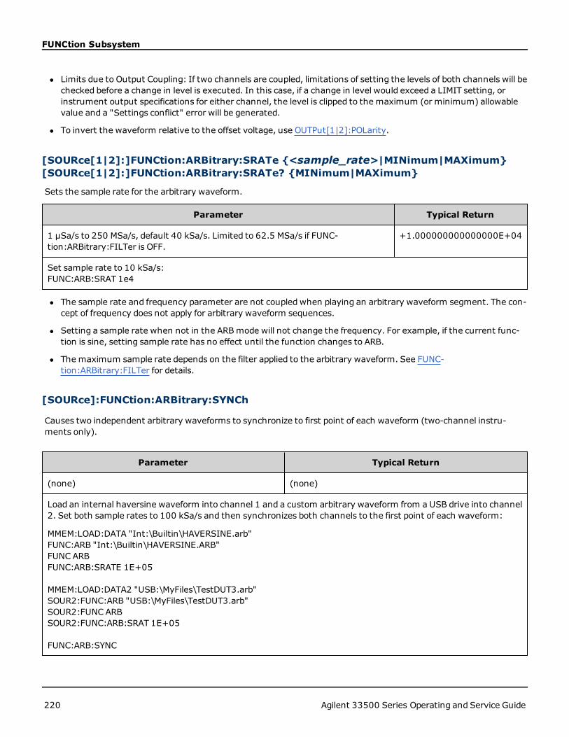
FUNCtion Subsystem
l Limits due to Output Coupling: If two channels are coupled, limitations of setting the levels of both channels will bechecked before a change in level is executed. In this case, if a change in level would exceed a LIMIT setting, orinstrument output specifications for either channel, the level is clipped to the maximum (or minimum) allowablevalue and a "Settings conflict" error will be generated.
l To invert the waveform relative to the offset voltage, use OUTPut[1|2]:POLarity.
[SOURce[1|2]:]FUNCtion:ARBitrary:SRATe {<sample_rate>|MINimum|MAXimum}[SOURce[1|2]:]FUNCtion:ARBitrary:SRATe? {MINimum|MAXimum}
Sets the sample rate for the arbitrary waveform.
Parameter Typical Return
1 µSa/s to 250 MSa/s, default 40 kSa/s. Limited to 62.5 MSa/s if FUNC-tion:ARBitrary:FILTer is OFF.
+1.000000000000000E+04
Set sample rate to 10 kSa/s:FUNC:ARB:SRAT 1e4
l The sample rate and frequency parameter are not coupled when playing an arbitrary waveform segment. The con-cept of frequency does not apply for arbitrary waveform sequences.
l Setting a sample rate when not in the ARBmode will not change the frequency. For example, if the current func-tion is sine, setting sample rate has no effect until the function changes to ARB.
l The maximum sample rate depends on the filter applied to the arbitrary waveform. See FUNC-tion:ARBitrary:FILTer for details.
[SOURce]:FUNCtion:ARBitrary:SYNCh
Causes two independent arbitrary waveforms to synchronize to first point of each waveform (two-channel instru-ments only).
Parameter Typical Return
(none) (none)
Load an internal haversine waveform into channel 1 and a custom arbitrary waveform from a USB drive into channel2. Set both sample rates to 100 kSa/s and then synchronizes both channels to the first point of each waveform:
MMEM:LOAD:DATA "Int:\Builtin\HAVERSINE.arb"FUNC:ARB "Int:\Builtin\HAVERSINE.ARB"FUNC ARBFUNC:ARB:SRATE 1E+05
MMEM:LOAD:DATA2 "USB:\MyFiles\TestDUT3.arb"SOUR2:FUNC:ARB "USB:\MyFiles\TestDUT3.arb"SOUR2:FUNC ARBSOUR2:FUNC:ARB:SRAT 1E+05
FUNC:ARB:SYNC
220 Agilent 33500 Series Operating and Service Guide

FUNCtion Subsystem
l This command stops and restarts the arbitrary waveforms on both channels at whatever sample rates they happento be set.
l If the two arbitrary waveforms have the same number of points, they will remain synchronized over multiple repe-titions; otherwise, they will only be synchronized at the beginning and after numbers of repetitions that happen tobe multiples of the number of points in both waveforms. For example, if you synchronize an 8-point waveform and a10-point waveform, they will re-synchronize after 40, 80, and 120 repetitions.
l This functionality is similar to using burst mode, but it operates in continuous wave mode.
l This command also works with burst, sweep, andmodulation, when trying to synchronize two arbitrary waveforms.
[SOURce[1|2]:]FUNCtion:NOISe:BANDwidth {<bandwidth>| MINimum | MAXimum}[SOURce[1|2]:]FUNCtion:NOISe:BANDwidth? [{MINimum | MAXimum}]
Sets bandwidth of noise function.
Parameter Typical Return
1 mHz to instrument's maximum frequency, default 100 kHz +6.000000000000000E+03
Set bandwidth to 20 kHZ:FUNC:NOISe:BWIDth 20000
The Noise function produces white gaussian noise with a Crest Factor of 4.6.
The noise bandwidth is continuously adjustable to place more noise energy in the frequency range from 0 Hz to thespecified noise bandwidth frequency.
[SOURce[1|2]:]FUNCtion:PRBS:BRATe {<bit_rate> | MINimum | MAXimum}[SOURce[1|2]:]FUNCtion:PRBS:BRATe? {<bit_rate>| MINimum | MAXimum}
Sets the pseudo-random binary sequence (PRBS) bit rate.
Parameter Typical Return
1 mbit/s to 50 Mbits/s, default 1000 bit/s +1.920000000000000E+04
Set bit rate to 19,200 bits per secondFUNC:PRBS:BRATe 19200
l A PRBS waveform using polynomial PNx is generated by a shift register of x bits, and the output waveform beginswith x sample periods of high output. Sample period is the reciprocal of the sample rate (FUNCtion:PRBS:BRATe),and the channel's Sync pulse indicates the waveform's start. For example, if the PRBS uses PN23 with samplerate 500 Hz, the output begins with 46 ms of high output (23 x 2 ms).
l The bit rate is independent of the data sequence length.
Agilent 33500 Series Operating and Service Guide 221

FUNCtion Subsystem
[SOURce[1|2]:]FUNCtion:PRBS:DATA <sequence_type>[SOURce[1|2]:]FUNCtion:PRBS:DATA?
Sets the pseudo-random binary sequence (PRBS) type. Setting the sequence type sets the length and feedback valuesas shown below.
Parameter Typical Return
{PN7|PN9|PN11|PN15|PN20|PN23}Value after PN corresponds tomaximum shift register length in bits.Default is PN7.
PN7, PN9, PN11, PN15, PN20, or PN23
Set data format to PN23:FUNC:PRBS:DATA PN23
l SYNCOutput may be active during a PRBS function, unlike the NOISe function.
l A PRBS waveform using polynomial PNx is generated by a shift register of x bits, and the output waveform beginswith x sample periods of high output. Sample period is the reciprocal of the sample rate (FUNCtion:PRBS:BRATe),and the channel's Sync pulse indicates the waveform's start. For example, if the PRBS uses PN23 with samplerate 500 Hz, the output begins with 46 ms of high output (23 x 2 ms). The polynomials are shown below.
Sequence Type Polynomial Feedback Length
PN7 x7+ x6+ 1 0x02000000 7
PN9 x9+ x5+ 1 0x04000000 9
PN11 x11+ x9+ 1 0x00400000 11
PN15 x15+ x14+ 1 0x00020000 15
PN20 x20+ x17+ 1 0x00004000 20
PN23 x23+ x18+ 1 0x00002000 23
[SOURce[1|2]:]FUNCtion:PRBS:TRANsition[:BOTH] {<seconds>|MI-Nimum|MAXimum}[SOURce[1|2]:]FUNCtion:PRBS:TRANsition[:BOTH]? [{MINimum|MAXimum}]
Sets PRBS transition edge time on both edges of a PRBS transition.
Parameter Typical Return
8.4 ns (default) to 1 μsec, limited as described below +1.000000000000000E-08
Set edge time to 10 ns for the leading and trailing edges (twomethods):FUNC:PRBS:TRAN 10 nsFUNC:PRBS:TRAN .000000010
222 Agilent 33500 Series Operating and Service Guide

FUNCtion Subsystem
l The default "BOTH" keyword is optional and allows simultaneous control of the leading and trailing edges of thePRBS waveform.
l The edge time applies to both the rising and falling edges, and represents the time between the 10% and 90%thresholds of each edge.
l The specified edge timemust fit within the specified period. The instrument will limit the edge time as needed toaccommodate the specified bit rate. From the remote interface, a "Settings conflict" error will also be generated.
[SOURce[1|2]:]FUNCtion:PULSe:DCYCle {<percent>|MINimum|MAXimum}[SOURce[1|2]:]FUNCtion:PULSe:DCYCle? [{MINimum|MAXimum}]
Sets pulse duty cycle.
Parameter Typical Return
0 to 100, limited as described below; default 10 +5.000000000000000E+01
Set duty cycle to 50%:FUNC:PULS:DCYC 50
l The FUNCtion:PULSe:DCYCle and FUNCtion:PULSe:WIDTh commands affect the same parameter. In some appli-cations, it is natural to adjust pulse width directly (in seconds); in others, adjusting duty cycle seemsmore natural.When frequency is adjusted, if pulse width wasmost recently adjusted as duty cycle on the front panel, then dutycycle will be kept constant as frequency or period changes. However, if pulse width was the last setting, then pulsewidth will be kept constant as frequency or period changes. See FUNCtion:PULSe:HOLD.
l The pulse duty cycle is defined as:
Duty Cycle = 100 x Pulse Width ÷ Period
Pulse width is the time from the 50% threshold of a pulse's rising edge to the 50% threshold of the next fallingedge.
l The pulse duty cycle range is 0 percent to 100 percent. However, the pulse duty cycle is limited byminimum pulsewidth and edge time restrictions, which prevent you from setting exactly 0 percent or 100 percent. For example,for a 1 kHz pulse waveform, you are typically restricted to pulse duty cycles in the range 0.002 percent to 99.998percent, limited by the minimum pulse width of 16 ns.
l Restrictions Based on Pulse Width: The specified pulse duty cycle must conform to the following restrictions deter-mined by theminimum pulse width (Wmin). The instrument will adjust pulse duty cycle as needed to accom-modate the specified period. From the remote interface, a "Settings conflict" error will also be generated.
Duty Cycle ≥ (Wmin / Period) X 100
and
Duty Cycle ≤ (1 – Wmin / Period) X 100
where Wmin = 20 ns
l Restrictions Based On and Affecting Edge Time: The specified pulse duty cycle may affect the edge time. The edgetime is adjusted first, and then the duty cycle is adjusted to accommodate the specified period, conforming to thefollowing restriction. From the remote interface, a "Settings conflict" error will also be generated.
Agilent 33500 Series Operating and Service Guide 223

FUNCtion Subsystem
Duty Cycle ≥ [(0.8 x Leading Edge Time) + (0.8 x Trailing Edge Time) ]/ Period x 100
and
Duty Cycle ≤ [1 – [(0.8 x Leading Edge Time) + (0.8 x Trailing Edge Time) ]/ Period] x 100
[SOURce[1|2]:]FUNCtion:PULSe:HOLD {WIDTh|DCYCle}[SOURce[1|2]:]FUNCtion:PULSe:HOLD?
Sets the pulse waveform parameter (either pulse width or duty cycle) to be held constant as other parameters are var-ied.
Parameter Typical Return
{WIDTh|DCYCle}, default WIDTh WIDT or DCYC
Set the instrument to hold duty cycle for pulse waveforms:FUNC:PULS:HOLD DCYC
l WIDTh: the instrument holds the pulse width setting (in seconds) constant as the period is varied. If a commandto set a duty cycle value is received, the duty cycle is converted to the equivalent pulse width. If pulse width mod-ulation (PWM) is turned on, the pulse width andwidth deviation are held as the period is varied. Duty cycle devi-ation commands are converted to width deviations.
Minimum width and edge time restrictions still apply. May cause a change in the selected edge times, pulse width,or both.
l DCYCle: the instrument holds the pulse duty cycle setting (in percent) constant as the period is varied. If a com-mand to set a pulse width value is received, the width is converted to the equivalent duty cycle. If pulse width mod-ulation (PWM) is turned on, the pulse duty cycle and the duty cycle deviation are held as the period is varied. Widthdeviation commands are converted to duty cycle deviation values.
Minimum width and edge time restrictions still apply. May cause a change in the selected edge times, duty cycle, orboth.
The FUNCtion:PULSe:HOLD command does not limit period settings. The pulse width or duty cyclemay be adjusted if necessary to accommodate a new period setting.
[SOURce[1|2]:]FUNCtion:PULSe:PERiod {<seconds>|MINimum|MAXimum}[SOURce[1|2]:]FUNCtion:PULSe:PERiod? [{MINimum|MAXimum}]
Sets the period for pulse waveforms. This command is paired with the FREQuency command; the one executed lastoverrides the other, as frequency and period specify the same parameter.
Parameter Typical Return
From reciprocal of instrument's maximum frequency up to 1,000,000 s. Default 1ms
+2.000000000000000E-07
Set the period to 500 ms:FUNC:PULS:PER .5orFUNC:PULS:PER 500 ms
224 Agilent 33500 Series Operating and Service Guide

FUNCtion Subsystem
l The specified periodmust be greater than the sum of the pulse width and the edge time. The instrument willadjust edge time and pulse width as needed to accommodate the specified period. From the remote interface, a"Settings conflict" error will also be generated. The edge time is minimized first, and then the width (or duty cycle)is adjusted as shown below.
Period ≥ [Pulse Width + ((Lead Edge Time + Trail Edge Time) * 0.625)]
l This command affects the period (and frequency) for all waveform functions (not just pulse). For example, if youselect a period using FUNCtion:PULSe:PERiod and then change the output function to sine wave, the specifiedperiod will be used for the new function.
l Function Limitations: If you change to a function whose minimum period exceeds the value set by this command,the period is adjusted to the new function's minimum pulse. For example, if you set a period of 2 µs and thenchange to the ramp function, the instrument adjusts the period to 5 µs (the minimum for ramps). From theremote interface, a "Settings conflict" error will also be generated.
[SOURce[1|2]:]FUNCtion:PULSe:TRANsition[:BOTH] {<seconds>|MI-Nimum|MAXimum}
[SOURce[1|2]:]FUNCtion:PULSe:TRANsition:LEADing {<seconds>|MI-Nimum|MAXimum}[SOURce[1|2]:]FUNCtion:PULSe:TRANsition:LEADing? [{MINimum|MAXimum}]
[SOURce[1|2]:]FUNCtion:PULSe:TRANsition:TRAiling {<seconds>|MI-Nimum|MAXimum}[SOURce[1|2]:]FUNCtion:PULSe:TRANsition:TRAiling? [{MINimum|MAXimum}]
Sets the pulse edge time on the leading, trailing, or both edges of a pulse.
Parameter Typical Return
8.4 ns to 1 µs, limited as described below; default 10 ns +1.000000000000000E-08
Set leading edge time to 10 ns (twomethods):FUNC:PULS:TRAN:LEADing 10 nsFUNC:PULS:TRAN:LEADing .000000010
l The leading edge time applies to rising edge, and represents the time from the 10% threshold to the 90% thresh-old of the edge; the trailing edge represents the time from the 90% threshold to the 10% threshold.
l The specified edge timemust fit within the specified pulse width and period. The instrument will limit the edge timeto accommodate the specified pulse width or duty cycle. From the remote interface, a "Settings conflict" error willalso be generated.
[SOURce[1|2]:]FUNCtion:PULSe:WIDTh {<seconds>|MINimum|MAXimum}[SOURce[1|2]:]FUNCtion:PULSe:WIDTh? [{MINimum|MAXimum}]
Sets pulse width.
Agilent 33500 Series Operating and Service Guide 225

FUNCtion Subsystem
Parameter Typical Return
16 ns to approximately 1,000,000 s, limited as described below; default 100 µs +5.000000000000000E-03
Set pulse width to 5 ms (twomethods):FUNC:PULS:WIDT 5 msFUNC:PULS:WIDT .005
l The FUNCtion:PULSe:DCYCle and FUNCtion:PULSe:WIDTh commands affect the same parameter. In some appli-cations, it is natural to adjust pulse width directly (in seconds); in others, adjusting duty cycle seemsmore natural.When frequency is adjusted, if pulse width wasmost recently adjusted as duty cycle on the front panel, then dutycycle will be kept constant as frequency or period changes. However, if pulse width was the last setting, then pulsewidth will be kept constant as frequency or period changes. See FUNCtion:PULSe:HOLD.
l Pulse width is the time from the 50% threshold of a pulse's rising edge to the 50% threshold of the next fallingedge.
l The specified pulse width must be less than the difference between the period and theminimum pulse width asshown below. The instrument will adjust pulse edge time first and then limit pulse width as needed to accom-modate the period.From the remote interface, a "Settings conflict" error will also be generated.
Pulse Width ≤ Period – Wmin
l The specified pulse width must also be less than the difference between the period and the edge time as shownbelow. The instrument will adjust pulse edge time first and then limit pulse width as needed to accommodate theperiod.From the remote interface, a "Settings conflict" error will also be generated.
Pulse Width ≤ [Period - ((Leading Edge Time + Trailing Edge Time) * 0.625)]
l The pulse width must also be greater than the total time of one edge as shown below.
Pulse Width ≥ [(Leading Edge Time + Trailing Edge Time) * 0.625]
[SOURce[1|2]:]FUNCtion:RAMP:SYMMetry {<percent>|MINimum|MAXimum}[SOURce[1|2]:]FUNCtion:RAMP:SYMMetry? [{MINimum|MAXimum}]
Sets the symmetry percentage for rampwaves.
Parameter Typical Return
0 to 100, default 100 +5.000000000000000E+01
Set symmetry to 50%:FUNC:RAMP:SYMM 50
l Symmetry represents the amount of time per cycle that the rampwave is rising (assuming that the waveformpolarity is not inverted).
Symmetry 0% Symmetry 100%
226 Agilent 33500 Series Operating and Service Guide

FUNCtion Subsystem
l For rampwaveforms, the APPLy:RAMP command overrides the current symmetry setting and selects 100%. Toset a symmetry other than 100%, select the rampwaveform output with the FUNCtion RAMP command, thenuse FUNCtion:RAMP:SYMMetry to set the symmetry.
l The symmetry setting is rememberedwhen you change from rampwave to another function. When you return tothe rampwave function, the previous symmetry is used.
l When ramp is the modulating waveform for AM, FM, PM, or PWM, the symmetry setting does not apply. The instru-ment always uses a rampwaveform with 100% symmetry.
[SOURce[1|2]:]FUNCtion:SQUare:DCYCle {<percent>|MINimum|MAXimum}[SOURce[1|2]:]FUNCtion:SQUare:DCYCle? [{MINimum|MAXimum}]
Sets duty cycle percentage for square wave.
Parameter Typical Return
0.01 to 99.99, subject to limitation of 16 nsminimum pulse width; default 50 +5.000000000000000E+01
Set duty cycle to 30%:FUNC:SQU:DCYC 30
Sets the duty cycle to 8%, if output frequency is 5 MHz:FUNC:SQU:DCYCMIN
l Duty cycle represents the amount of time per cycle that the square wave is at a high level (assuming normal polar-ity).
l For square waveforms, APPLy:SQUare replaces the current duty cycle setting with 50%. To set a duty cycle otherthan 50%, select the square wave with FUNCtion SQUare, then use FUNCtion:SQUare:DCYCle.
l The duty cycle setting is rememberedwhen you change from square wave to another function. When you returnto square wave, the previous duty cycle is used.
l Limits Due to Frequency: As frequency is increased, minimum andmaximum duty cycle limits are adjusted tomaintain a minimum pulse width of 16 ns. For example, at 1 MHz the minimum duty cycle is 1.60% andmax-imum duty cycle is 98.40%. At 10 MHz, the minimum duty cycle is 16.00% and the maximum duty cycle is84.00%.
l If you select a square waveform as the modulating waveform for AM, FM, PM, or PWM, the instrument always usesa square wave with 50% duty cycle.
[SOURce[1|2]:]FUNCtion:SQUare:PERiod {<seconds>|MINimum|MAXimum}[SOURce[1|2]:]FUNCtion:SQUare:PERiod? [{MINimum|MAXimum}]
Sets period for square wave.
Parameter Typical Return
33.3 ns to 1,000,000 s, default 1 ms +5.000000000000000E-01
Set period to 500 ms (twomethods):FUNC:SQUare:PER .5FUNC:SQUare:PER 500 ms
Agilent 33500 Series Operating and Service Guide 227

FUNCtion Subsystem
l Function Limitations: If you change to a function whose minimum period exceeds the value set by this command,the period is adjusted to the new function's minimum pulse. For example, if you set a period of 2 µs and thenchange to the ramp function, the instrument adjusts the period to 5 µs (the minimum for ramps). From theremote interface, a "Settings conflict" error will also be generated.From the remote interface, a "Settings conflict"error will also be generated.
The commands shown below all require the IQ player option.
FUNCtion:ARBitrary:BALance[:STATe] <state>FUNCtion:ARBitrary:BALance:[:STATe]?This command requires the IQ Player option.
Enables or disables channel balancing for dual arbitrary waveforms (FUNCtion:ARBitrary:BALance:GAIN and FUNC-tion:ARBitrary:BALance:OFFSet).
Parameter Typical Return
{ON|1|OFF|0}, default OFF 0 (OFF) or 1 (ON)
Load an arbitrary waveform from the USB drive and set up the balance gain (channel 2 down by 1.02%) and balanceoffsets (120 mV for channel 1 and -38 mV for channel 2):
FUNC:ARB "USB:\qam32.barb"FUNC:ARB:BAL:GAIN 1.02FUNC:ARB:BAL:OFFS1 0.12FUNC:ARB:BAL:OFFS2 -0.038FUNC:ARB:BAL ON
l This feature can be used to compensate for minor variations in the load impedances on the two channels, or forminor differences between the two channels of information in the original dual arbitrary waveform file.
l When the <state> is on, both channels must stay on the same amplifier range.
l This setting is stored as part of the instrument state, and it is affected by *RST.
FUNCtion:ARBitrary:BALance:GAIN {<percent>|MAXimum|MINimum}FUNCtion:ARBitrary:BALance:GAIN? {MAXimum|MINimum}This command requires the IQ Player option.
Sets the gain balance ratio for dual arbitrary waveforms.
Parameter Typical Return
-30 to +30 +1.02000000E+000
228 Agilent 33500 Series Operating and Service Guide

FUNCtion Subsystem
Parameter Typical Return
Load an arbitrary waveform from the USB drive and set up the balance gain (channel 2 down by 1.02%) and balanceoffsets (120 mV for channel 1 and -38 mV for channel 2):
FUNC:ARB "USB:\qam32.barb"FUNC:ARB:BAL:GAIN 1.02FUNC:ARB:BAL:OFFS1 0.12FUNC:ARB:BAL:OFFS2 -0.038FUNC:ARB:BAL ON
l Both channels must stay on the same amplifier range.
l A value of 0 means that both channels use their current amplitude. A positive value means that the amplitude ofchannel 2 is pushed down, while the amplitude of channel 1 remains constant, a negative value pushes channel 1down while holding channel 2 constant. See the following table for examples.
l
<percent> Channel 1Amplitude %
Channel 2Amplitude %
-20 80 100
-10 90 100
0 100 100
10 100 90
20 100 80
l This command is enabled by FUNCtion:ARBitrary:BALance ON.
l This setting is stored as part of the instrument state, and it is affected by *RST.
FUNCtion:ARBitrary:BALance:OFFSet[1|2] {<volts>|MAXimum|MINimum}FUNCtion:ARBitrary:BALance:OFFSet[1|2]? {MAXimum|MINimum}This command requires the IQ Player option.
Specifies the offset (in volts) added to the dual arbitrary waveform offset for the specified channel.
Parameter Typical Return
A floating point value, limited by the dual arbitrary wave-form amplitude.
+1.00000000E+000
Load an arbitrary waveform from the USB drive and set up the balance gain (channel 2 down by 1.02%) and balanceoffsets (120 mV for channel 1 and -38 mV for channel 2):
FUNC:ARB "USB:\qam32.barb"FUNC:ARB:BAL:GAIN 1.02FUNC:ARB:BAL:OFFS1 0.12FUNC:ARB:BAL:OFFS2 -0.038FUNC:ARB:BAL ON
Agilent 33500 Series Operating and Service Guide 229

FUNCtion Subsystem
l Both channels must stay on the same amplifier range.
l This command is enabled by FUNCtion:ARBitrary:BALance ON.
l This setting is stored as part of the instrument state, and it is affected by *RST.
FUNCtion:ARBitrary:SKEW[:STATe] <state>FUNCtion:ARBitrary:SKEW[:STATe]?This command requires the IQ Player option.
Enables or disables skew time compensation (FUNCtion:ARBitrary:SKEW:TIME). This is always OFF for modulated sig-nals, sweeps, lists, and bursts.
Parameter Typical Return
{ON|1|OFF|0}, default OFF 0 (OFF) or 1 (ON)
Set the skew time to compensate for channel 1 being behind channel 2 by 140 picoseconds:FUNCtion:ARBitrary:SKEW:TIME 1.4e-10FUNCtion:ARBitrary:SKEW ON
l Skew compensation is typically determined empirically, using an oscilloscope and then set one time. That one-timesetupwill then be valid until the DUT or test equipment configuration changes.
l The value specified by this command is not stored in the instrument state. It is stored in non-volatile memory and isnot affected by *RST.
FUNCtion:ARBitrary:SKEW:TIME [{<time>|MINimum|MAXimum}]FUNCtion:ARBitrary:SKEW:TIME? [{MINimum|MAXimum}]This command requires the IQ Player option.
Sets a small time difference between the channels to compensate for minor variations in timing at the connector out-put plane or at the device under test (DUT). Note than FUNC:ARB:SKEW[:STATe] OFF for modulated signals, sweeps,lists, and bursts.
Parameter Typical Return
A floating point value in the range of ±4 ns. Default 0. +1.40000000E-010
Set the skew time to compensate for channel 1 being behind channel 2 by 140 picoseconds:FUNCtion:ARBitrary:SKEW:TIME 1.4e-10FUNCtion:ARBitrary:SKEW ON
l Channels may exhibit slight timing variations at the output connector plane due to variations in internal circuitrybetween the two channels. They may exhibit slight timing variations at the device under test (DUT) due to var-iations in signal paths, including such things as switches and cable lengths.
230 Agilent 33500 Series Operating and Service Guide

FUNCtion Subsystem
l A positive value delays channel 2, and a negative value delays channel 1.
l The value specified by this command is not stored in the instrument state. It is stored in non-volatile memory and isnot affected by *RST.
Agilent 33500 Series Operating and Service Guide 231
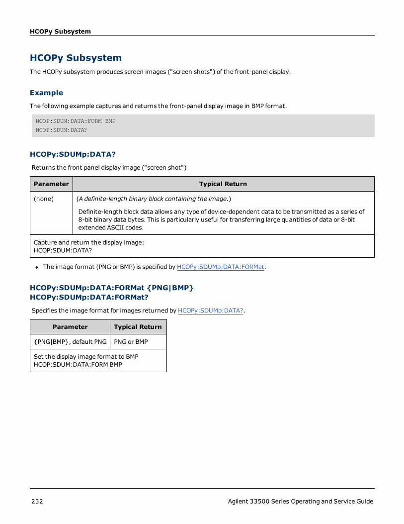
HCOPy Subsystem
HCOPy SubsystemThe HCOPy subsystem produces screen images ("screen shots") of the front-panel display.
Example
The following example captures and returns the front-panel display image in BMP format.
HCOP:SDUM:DATA:FORM BMP
HCOP:SDUM:DATA?
HCOPy:SDUMp:DATA?
Returns the front panel display image ("screen shot")
Parameter Typical Return
(none) (A definite-length binary block containing the image.)
Definite-length block data allows any type of device-dependent data to be transmitted as a series of8-bit binary data bytes. This is particularly useful for transferring large quantities of data or 8-bitextended ASCII codes.
Capture and return the display image:HCOP:SDUM:DATA?
l The image format (PNG or BMP) is specified by HCOPy:SDUMp:DATA:FORMat.
HCOPy:SDUMp:DATA:FORMat {PNG|BMP}HCOPy:SDUMp:DATA:FORMat?
Specifies the image format for images returned by HCOPy:SDUMp:DATA?.
Parameter Typical Return
{PNG|BMP}, default PNG PNG or BMP
Set the display image format to BMPHCOP:SDUM:DATA:FORM BMP
232 Agilent 33500 Series Operating and Service Guide
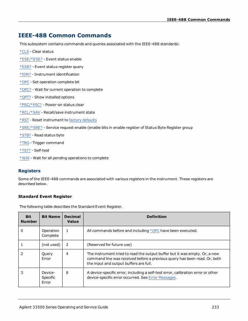
IEEE-488 Common Commands
IEEE-488 Common CommandsThis subsystem contains commands and queries associated with the IEEE-488 standards:
*CLS - Clear status
*ESE/*ESE? - Event status enable
*ESR? - Event status register query
*IDN? - Instrument identification
*OPC - Set operation complete bit
*OPC? -Wait for current operation to complete
*OPT? - Show installed options
*PSC/*PSC? - Power-on status clear
*RCL/*SAV - Recall/save instrument state
*RST - Reset instrument to factory defaults
*SRE/*SRE? - Service request enable (enable bits in enable register of Status Byte Register group
*STB? - Read status byte
*TRG - Trigger command
*TST? - Self-test
*WAI -Wait for all pending operations to complete
Registers
Some of the IEEE-488 commands are associated with various registers in the instrument. These registers aredescribed below.
Standard Event Register
The following table describes the Standard Event Register.
BitNumber
Bit Name DecimalValue
Definition
0 OperationComplete
1 All commands before and including *OPC have been executed.
1 (not used) 2 (Reserved for future use)
2 QueryError
4 The instrument tried to read the output buffer but it was empty. Or, a newcommand line was received before a previous query has been read. Or, boththe input and output buffers are full.
3 Device-SpecificError
8 A device-specific error, including a self-test error, calibration error or otherdevice-specific error occurred. See Error Messages.
Agilent 33500 Series Operating and Service Guide 233

IEEE-488 Common Commands
BitNumber
Bit Name DecimalValue
Definition
4 ExecutionError
16 An execution error occurred. Error Messages
5 Command 32 A command syntax error occurred. Error Messages
6 (not used) 64 (Reserved for future use)
7 Power On 128 Power has been cycled since the last time the event register was read orcleared.
Status Byte Register
The following table describes the Status Byte Register.
BitNumber
Bit Name DecimalValue
Definition
0 (not used) 1 (Reserved for future use)
1 (not used) 2 (Reserved for future use)
2 Error Queue 4 One or more errors in the Error Queue. Use SYSTem:ERRor? to read anddelete errors.
3 QuestionableData Summary
8 One or more bits are set in the Questionable Data Register (bits must beenabled, see STATus:QUEStionable:ENABle ).
4 Message Avail-able
16 Data is available in the instrument's output buffer.
5 StandardEvent Sum-mary
32 One or more bits are set in the Standard Event Register (bits must be ena-bled, see *ESE).
6 Master Sum-mary
64 One or more bits are set in the Status Byte Register andmay generate aRequest for Service (RQS). Bits must be enabled using *SRE.
7 Operation Reg-ister
128 One or more bits are set in the Operation Status Register. Bits are ena-bled using STATus:OPERation:ENABle.
*CLS
Clear Status Command. Clears the event registers in all register groups. Also clears the error queue.
Parameter Typical Return
(none) (none)
Clear event register bits and error queue:*CLS
234 Agilent 33500 Series Operating and Service Guide

IEEE-488 Common Commands
*ESE <enable_value>*ESE?
Event Status Enable Command andQuery. Enables bits in the enable register for the Standard Event Register group.The selected bits are then reported to bit 5 of the Status Byte Register.
Parameter TypicalReturn
Decimal sum of the bits in the register (table below), default 0. For example, to enable bit 2 (value4), bit 3 (value 8), and bit 7 (value 128), the decimal sum would be 140 (4 + 8 + 128). Default 0.
+48
Enable bit 4 (value 16) and bit 5 (value 32) in the enable register:*ESE 48
l Use *PSC to control whether the Standard Event enable register is cleared at power on. For example, *PSC 0 pre-serves the enable register contents through power cycles.
l *CLS does not clear enable register, does clear event register.
*ESR?
Standard Event Status Register Query. Queries the event register for the Standard Event Register group. Register isread-only; bits not cleared when read.
Parameter Typical Return
(none) +24
Read the event register (bits 3 and 4 are set).*ESR
l Any or all conditions can be reported to the Standard Event summary bit through the enable register. To set theenable register mask, write a decimal value to the register using *ESE.
l Once a bit is set, it remains set until cleared by this query or *CLS.
*IDN?
Identification Query. Returns instrument’s identification string.
Parameter Typical Return
(none) Agilent Technologies,33522B,XXXXXXXXXX,0.179-1.19-8.88-52-00
Return the instrument's identification string:*IDN?
l Identification string contains four comma separated fields:
l Manufacturer name
l Model number
Agilent 33500 Series Operating and Service Guide 235
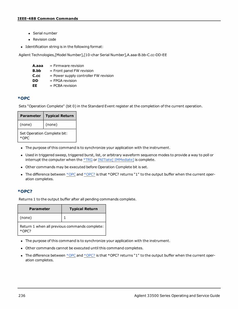
IEEE-488 Common Commands
l Serial number
l Revision code
l Identification string is in the following format:
Agilent Technologies,[Model Number],[10-char Serial Number],A.aaa-B.bb-C.cc-DD-EE
A.aaa = Firmware revisionB.bb = Front panel FW revisionC.cc = Power supply controller FW revisionDD = FPGA revisionEE = PCBA revision
*OPC
Sets "Operation Complete" (bit 0) in the Standard Event register at the completion of the current operation.
Parameter Typical Return
(none) (none)
Set Operation Complete bit:*OPC
l The purpose of this command is to synchronize your application with the instrument.
l Used in triggered sweep, triggered burst, list, or arbitrary waveform sequence modes to provide a way to poll orinterrupt the computer when the *TRG or INITiate[:IMMediate] is complete.
l Other commandsmay be executed before Operation Complete bit is set.
l The difference between *OPC and *OPC? is that *OPC? returns "1" to the output buffer when the current oper-ation completes.
*OPC?
Returns 1 to the output buffer after all pending commands complete.
Parameter Typical Return
(none) 1
Return 1 when all previous commands complete:*OPC?
l The purpose of this command is to synchronize your application with the instrument.
l Other commands cannot be executed until this command completes.
l The difference between *OPC and *OPC? is that *OPC? returns "1" to the output buffer when the current oper-ation completes.
236 Agilent 33500 Series Operating and Service Guide

IEEE-488 Common Commands
*OPT?
Returns a quoted string identifying any installed options.
Parameter Typical Return
(none) "0,MEM,SEC,IQP"
Returns installed options (example: standard timebase, extendedmemory, security, IQ player)*OPT?
*PSC {0|1}*PSC?
Power-On Status Clear. Enables (1) or disables (0) clearing of two specific registers at power on:
l Standard Event enable register (*ESE).
l Status Byte condition register (*SRE).
l Questionable Data Register
l Standard Operation Register
Parameter Typical Return
{0|1}, default 1 0 or 1
Disables power-on clearing of affected registers:*PSC 0
*RCL {0|1|2|3|4}*SAV {0|1|2|3|4}
Recalls (*RCL) or saves (*SAV) instrument state in specified non-volatile location. Previously stored state in location isoverwritten (no error is generated).
Parameter Typical Return
{0|1|2|3|4} (none)
Recall state from location 1:*RCL 1
l The instrument has five non-volatile storage locations to store instrument states. Location 0 holds the instrumentpower down state. Use locations 1, 2, 3, and 4 to store other states. You can configure the instrument to recall thepower-down state when power is restored (MEM:STAT:REC:AUTO).
l State storage "remembers" the selected function (including arbitrary waveforms), frequency, amplitude, DC off-set, duty cycle, symmetry, as well as any modulation parameters in use. Also remembers front-panel display state(DISP).
l When shipped from the factory, locations 1 through 4 are empty, and location 0 has power-on state.
Agilent 33500 Series Operating and Service Guide 237

IEEE-488 Common Commands
l From the remote interface only, you can use location 0 to store a fifth instrument state (you cannot store to thislocation from the front panel). However, location 0 is overwritten when power is cycled.
l You can assign a user-defined name to each of locations 0 through 4.
l States stored in memory are not affected by *RST.
l If you delete an arbitrary waveform from non-volatile memory after storing the instrument state, the waveformdata is lost and the instrument will not output the waveform when the state is recalled; it will output the built-in"exponential rise" instead.
l The front panel uses MMEMory subsystem for state storage.
*RST
Resets instrument to factory default state, independent of MEMory:STATe:RECall:AUTO setting.
Parameter Typical Return
(none) (none)
Reset the instrument:*RST
l Does not affect stored instrument states, stored arbitrary waveforms, or I/O settings; these are stored in non-vol-atile memory.
l Aborts a sweep or burst in progress.
*SRE <enable_value>*SRE?
Service Request Enable. This command enables bits in the enable register for the Status Byte Register group.
Parameter TypicalReturn
Decimal sum of the bits in the register (table below), default 0. For example, to enable bit 2 (value 4), bit3 (value 8), and bit 7 (value 128), the decimal sum would be 140 (4 + 8 + 128). Default 0.
+24
Enable bits 3 and 4 in the enable register:*SRE 24
l To enable specific bits, specify the decimal value corresponding to the binary-weighted sum of the bits in the reg-ister. The selected bits are summarized in the "Master Summary" bit (bit 6) of the Status Byte Register. If any ofthe selected bits change from 0 to 1, the instrument generates a Service Request signal.
l *CLS clears the event register, but not the enable register.
l *PSC (power-on status clear) determines whether Status Byte enable register is cleared at power on. For example,*PSC 0 preserves the contents of the enable register through power cycles.
l Status Byte enable register is not cleared by *RST.
238 Agilent 33500 Series Operating and Service Guide

IEEE-488 Common Commands
*STB?
Read Status Byte Query. This command queries the condition register for the Status Byte Register group.
Parameter Typical Return
(none) +40
Read condition register (with bits 3 and 5 set):*STB?
l Similar to a Serial Poll, but processed like any other instrument command. Register is read-only; bits not clearedwhen read.
l Returns same result as a Serial Poll, but "Master Summary" bit (bit 6) is not cleared by *STB?.
l Power cycle or *RST clears all bits in condition register.
l Returns a decimal value that corresponds to the binary-weighted sum of all bits set in the register. For example,with bit 3 ( value 8) and bit 5 (value 32) set (and corresponding bits enabled), the query returns +40.
*TRG
Trigger Command. Triggers a sweep, burst, arbitrary waveform advance, or LIST advance from the remote interface ifthe bus (software) trigger source is currently selected (TRIGger[1|2]:SOURce BUS).
Parameter Typical Return
(none) (none)
Send immediate trigger to initiate a burst:BURS:STAT ONBURS:MODE TRIGTRIG:SOUR BUS*TRG
*TST?
Self-Test Query. Performs a complete instrument self-test. If test fails, one or more error messages will provide addi-tional information. Use SYSTem:ERRor? to read error queue.
Parameter Typical Return
(none) +0 (pass) or +1 (one or more tests failed)
Perform self-test:*TST?
l A power-on self-test occurs when you turn on the instrument. This limited test assures you that the instrument isoperational.
Agilent 33500 Series Operating and Service Guide 239

IEEE-488 Common Commands
l A complete self-test (*TST?) takes approximately 15 seconds. If all tests pass, you have high confidence that theinstrument is fully operational.
l Passing *TST displays "Self-Test Passed" on the front panel. Otherwise, it displays "Self-Test Failed" and an errornumber. See Service and Repair - Introduction for instructions on contacting support or returning the instrumentfor service.
*WAI
Configures the instrument to wait for all pending operations to complete before executing any additional commandsover the interface.
Parameter Typical Return
(none) (none)
Wait until all pending operations complete.*WAI
240 Agilent 33500 Series Operating and Service Guide

Registers
RegistersThe instrument uses three different type of registers to enable, flag and track instrument features.
l An enable register defines which bits in the event register will be reported to the Status Byte register group. You canwrite to or read from an enable register.
l A condition register continuously monitors the state of the instrument. The bits in the condition register areupdated in real time and the bits are not latched or buffered.
l An event register latches the various events from the condition register. There is no buffering in this register; whilean event bit is set, subsequent events corresponding to that bit are ignored. This is a read-only register.
Agilent 33500 Series Operating and Service Guide 241

INITiate Subsystem
INITiate SubsystemThe INITiate subsystem controls how the instrument moves from the "idle" state to the "wait for trigger" state. Youmay do this one channel at a time, or for both channels with the "ALL" keyword.
Example
This program uses INITiate[1|2][:IMMediate] with TRIGger[1|2]:SOURce and TRIGger[1|2]:COUNt. The TRIG:SOUREXT command configures the channel for external triggering, and TRIG:COUNT sets the trigger count to 10. The INI-Tiate command places the instrument in the "wait-for-trigger" state. The trigger will occur when the rear-panel ExtTrig line is pulsed (high by default). The channel will return to idle after the trigger count of 10 has been satisfied.Another INIT commandwould then be necessary to restart the acceptance of triggers from the external trigger inputline.
INIT:CONT OFF
TRIG:SOUR EXT
TRIG:COUNT 10
INIT
INITiate[1|2]:CONTinuous {ON|1|OFF|0}INITiate[1|2]:CONTinuous?
INITiate:CONTinuous:ALL {ON|1|OFF|0}
Specifies whether the trigger system for one or both channels (ALL) always returns to the "wait-for-trigger" state (ON)or remains in the "idle" state (OFF), ignoring triggers until INITiate:IMMediate is issued.
Parameter Typical Return
{ON|1|OFF|0}, default ON 0 (OFF) or 1 (ON)
Configure both channels for continuous trigger:INIT:CONT:ALL ON
l Once the channel is triggered, it leaves the wait-for-trigger state and enters the "action-in-progress" state (forexample, burst-in-progress or sweep-in-progress). The action-in-progress state can be lengthy, and during thisstate triggers are ignored (will not count against number of triggers specified by TRIGger[1|2]:COUNt).
INITiate[1|2][:IMMediate]
INITiate[:IMMediate]:ALL
Change state of triggering system for both channels (ALL) from "idle" to "wait-for-trigger" for the number of triggersspecified by TRIGger[1|2]:COUNt.
l Once the channel is triggered, it leaves the wait-for-trigger state and enters the "action-in-progress" state (forexample, burst-in-progress or sweep-in-progress). The action-in-progress state can be lengthy, and during thisstate triggers are ignored (will not count against number of triggers specified by TRIGger[1|2]:COUNt).
242 Agilent 33500 Series Operating and Service Guide

INITiate Subsystem
Parameter Typical Return
(none) (none)
Change both channels to the wait-for-trigger state:INIT:IMM:ALL
l The trigger system is armed by INITiate[:IMMediate]. Once the trigger count is satisfied, the trigger systemreturns to idle state and ignores further triggers. The triggered function will be left in whatever state is achievedwith the count of triggers. Rearming the trigger system with another INITiate[:IMMediate] allows further triggersto apply.
l Use ABORt to return instrument to idle.
l If the specified channel has INIT:CONT set ON, INITiate[1|2]:IMMediate and INIT[:IMMediate]:ALL have no effecton the trigger system and error -213 will be generated.
Agilent 33500 Series Operating and Service Guide 243

LIST Subsystem
LIST SubsystemConfigures list of frequencies to be output by instrument. This permits faster frequency change to a predetermined listof frequencies. You may advance frequencies by either an external trigger, an internal trigger, or a BUS trigger. List isinitiated by FREQuency:MODE LIST.
LIST:DWELl - sets amount of time each frequency in list is generated.
LIST:FREQuency - Specify up to 128 frequencies as a list (frequencies may also be read from or saved to a file usingMMEMory:LOAD:LIST[1|2] andMMEMory:STORe:LIST.
LIST:FREQuency:POINts? - Returns number of points in a frequency list.
For LIST programming example, see Create a List of Frequencies.
[SOURce[1|2]:]LIST:DWELl {<seconds>|MINimum|MAXimum}[SOURce[1|2]:]LIST:DWELl? [{MINimum|MAXimum}]
Sets dwell time, the amount of time each frequency in a frequency list is generated.
Parameter Typical Return
1 µs to 1000 s, default 1 s +1.200000000000000E+01
Set dwell time for channel 1 to 12 s:LIST:DWEL 12
l The instrument generates each frequency in a frequency list for the specified dwell time, when TRIGger[1|2]:SOURce is IMMediate.
[SOURce[1|2]:]LIST:FREQuency <freq1>[, <freq2>, etc.][SOURce[1|2]:]LIST:FREQuency?
Specifies frequency values in a frequency list.
Parameter Typical Return
List of 1 to 128 frequencies, each 1 μHz tomaximum instrumentfrequency (up to 200 kHz for triangle and ramp). Default list: 100 Hz,1000 Hz, and 550 Hz.
2.17800000E+006,3.14000000E+003,6.28318000E+006
Set channel 1 frequency list to three frequency values:LIST:FREQ 2.718E6, 3.14E3, 6.28318E6
l Command overwrites previous list with new list.
[SOURce[1|2]:]LIST:FREQuency:POINts? [{MINimum|MAXimum}]
Returns number of frequencies in current frequency list.
244 Agilent 33500 Series Operating and Service Guide

LIST Subsystem
Parameter Typical Return
{MINimum|MAXimum} +17
Return number of entries in the channel 1 frequency list:LIST:FREQ:POIN?
l Default is list of three frequencies: 100 Hz, 1000 Hz, and 550 Hz.
l MINimum is 1, MAXimum is 128.
Agilent 33500 Series Operating and Service Guide 245

LXI Subsystem
LXI SubsystemThe LXI subsystem supports LAN eXtensions for Instrumentation (LXI) functionality.
LXI:IDENtify[:STATE] {ON|1|OFF|0}LXI:IDENtify[:STATE]?
Turns the LXI Identify Indicator on the display on or off.
Parameter Typical Return
{ON|1|OFF|0} 0 (OFF) or 1 (ON)
Turn on the LXI Identify Indicator:LXI:IDEN ON
l The LXI Identify indicator helps you identify the device associated with the LAN address.
l A *RST turns LXI Identify Indicator off.
l Pressing the LOCAL key turns off the LXI Identify Indicator.
LXI:MDNS:ENABle {ON|1|OFF|0}LXI:MDNS:ENABle?
Disables or enables the Multicast Domain Name System (mDNS).
Parameter Typical Return
{ON|1|OFF|0}, default ON 0 (OFF) or 1 (ON)
Turn mDNS ON:LXI:MDSN:ENAB ON
l Setting is enabled after SYSTem:SECurity:IMMediate, *RST, power-on, or LAN reset.
LXI:MDNS:HNAMe[:RESolved]?
Returns the resolved (unique)mDNS hostname in the form <mDNS Hostname>-N. The N is an integer appended ifnecessary to make the name unique. The desired namemay be truncated, if necessary, to make room for theappended integer.
Parameter Typical Return
(none) "A-335xxx-00107", where xxx is the last three characters of the model number, and 00107 is thelast five digits of the serial number.
Return the resolvedmDNS hostname:LXI:MDNS:HNAMe:RESolved?
246 Agilent 33500 Series Operating and Service Guide

LXI Subsystem
LXI:MDNS:SNAMe:DESired <name>LXI:MDNS:SNAMe:DESired?
Sets the desiredmDNS service name.
Parameter Typical Return
Quoted string of up to 63 characters, default isAgilent <Model_Name> Arbitrary WaveformGenerator - <Serial_Number>".
"Agilent 335xxx Arbitrary Waveform Generator - 99999", wherexxx is the last three characters of the model number, and 99999is the last five digits of the serial number.
Set the mDNS service name to "Waveform Generator":LXI:MDNS:SNAM:DES "Waveform Generator"
l This setting is non-volatile; it will not be changed by power cycling or *RST.
l Setting is set to default value after SYSTem:SECurity:IMMediate.
LXI:MDNS:SNAMe[:RESolved]?
Returns the resolved (unique)mDNS service name in the form <DesiredmDNS Service Name>(N). The N is aninteger appended if necessary to make the name unique. The desired namemay be truncated, if necessary, to makeroom for the appended integer.
Parameter Typical Return
(none) "Agilent 335xxx Arbitrary Waveform Generator - 00309", where xxx is the last three characters ofthe model number, and 00309 is the last five digits of the serial number.
Return resolvedmDNS service name:LXI:MDNS:SNAMe:RESolved?
l The resolvedmDNS service name will be the desired service name (LXI:MDNS:SNAMe:DESired), possibly with "(N)" appended, where N is an integer, only if if is necessary to make the name unique.
LXI:RESet
Resets LAN settings to a known operating state, beginning with DHCP. If DHCP fails, it uses AutoIP. It also clears theWebUI password, if set.
Parameter Typical Return
(none) (none)
Reset the LAN settings:LXI:RES
l Depending on your network, the LAN interface may take several seconds to restart after this command is sent.
l If the LAN interface or specific LAN services (VXI-11, sockets, and so on) have been disabled by SYS-Tem:COMMunicate:ENABle, you must separately re-enable the interface or services and cycle power on the instru-ment for the LAN to be operational.
Agilent 33500 Series Operating and Service Guide 247

LXI Subsystem
LXI:RESTart
Restarts the LAN with the current settings as specified by the SYSTem:COMM:LAN commands.
Parameter Typical Return
(none) (none)
Restart the LAN interface:LXI:REST
l Depending on your network, the LAN interface may take several seconds to restart after this command is sent.
l If the LAN interface or specific LAN services (VXI-11, sockets, and so on) have been disabled by SYS-Tem:COMMunicate:ENABle, you must separately re-enable the interface or services and cycle power on the instru-ment for the LAN to be operational.
248 Agilent 33500 Series Operating and Service Guide
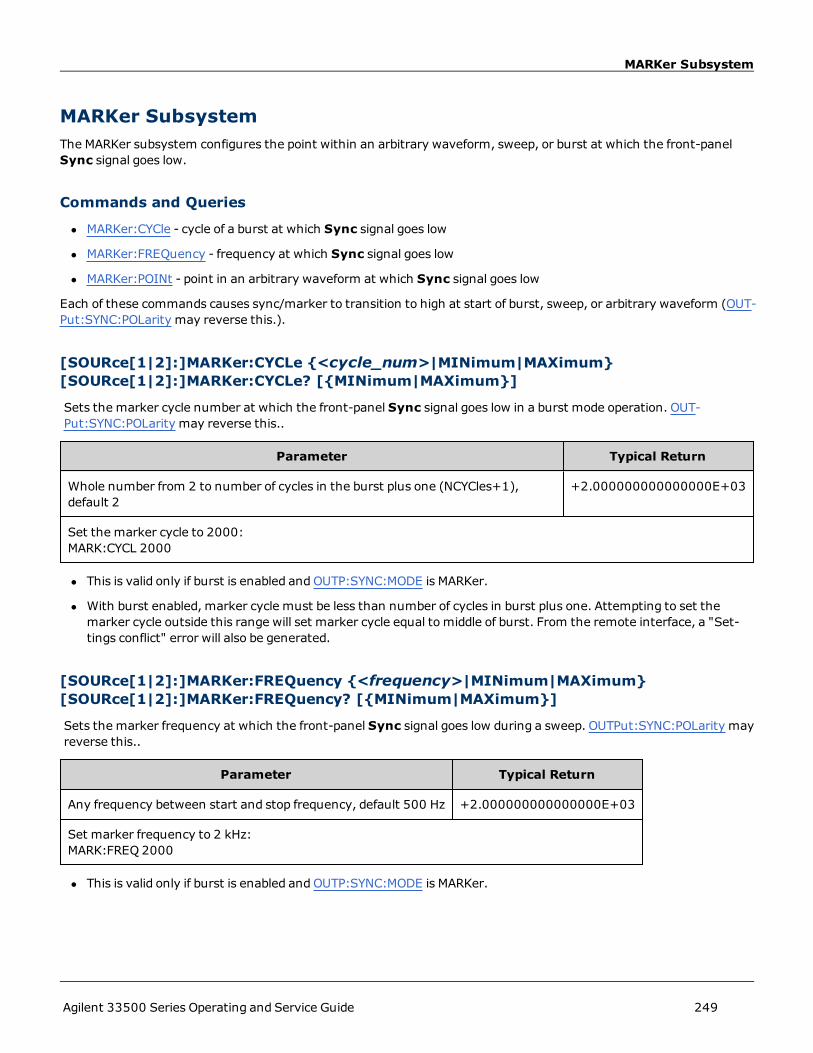
MARKer Subsystem
MARKer SubsystemThe MARKer subsystem configures the point within an arbitrary waveform, sweep, or burst at which the front-panelSync signal goes low.
Commands and Queries
l MARKer:CYCle - cycle of a burst at which Sync signal goes low
l MARKer:FREQuency - frequency at which Sync signal goes low
l MARKer:POINt - point in an arbitrary waveform at which Sync signal goes low
Each of these commands causes sync/marker to transition to high at start of burst, sweep, or arbitrary waveform (OUT-Put:SYNC:POLarity may reverse this.).
[SOURce[1|2]:]MARKer:CYCLe {<cycle_num>|MINimum|MAXimum}[SOURce[1|2]:]MARKer:CYCLe? [{MINimum|MAXimum}]
Sets the marker cycle number at which the front-panel Sync signal goes low in a burst mode operation. OUT-Put:SYNC:POLarity may reverse this..
Parameter Typical Return
Whole number from 2 to number of cycles in the burst plus one (NCYCles+1),default 2
+2.000000000000000E+03
Set the marker cycle to 2000:MARK:CYCL 2000
l This is valid only if burst is enabled andOUTP:SYNC:MODE is MARKer.
l With burst enabled, marker cycle must be less than number of cycles in burst plus one. Attempting to set themarker cycle outside this range will set marker cycle equal to middle of burst. From the remote interface, a "Set-tings conflict" error will also be generated.
[SOURce[1|2]:]MARKer:FREQuency {<frequency>|MINimum|MAXimum}[SOURce[1|2]:]MARKer:FREQuency? [{MINimum|MAXimum}]
Sets the marker frequency at which the front-panel Sync signal goes low during a sweep. OUTPut:SYNC:POLarity mayreverse this..
Parameter Typical Return
Any frequency between start and stop frequency, default 500 Hz +2.000000000000000E+03
Set marker frequency to 2 kHz:MARK:FREQ 2000
l This is valid only if burst is enabled andOUTP:SYNC:MODE is MARKer.
Agilent 33500 Series Operating and Service Guide 249

MARKer Subsystem
l When sweep is enabled, marker frequency must be between start frequency and stop frequency. Attempting toset the marker cycle outside this range will set marker frequency to start frequency or frequency (whichever iscloser). From the remote interface, a "Settings conflict" error will also be generated.
[SOURce[1|2]:]MARKer:POINt {<sample_number>|MINimum|MAXimum}[SOURce[1|2]:]MARKer:POINt? [{MINimum|MAXimum}]
Sets the sample number at which the front-panel Sync signal goes low within the active arbitrary waveform. OUT-Put:SYNC:POLarity may reverse this..
Parameter Typical Return
Whole number from 4 to number of samples in waveform,minus 3; default is mid-point of arbitrary waveform
+1.000000000000000E+01
Set marker point to 10th sample in waveform:MARK:POIN 10
l Command only sets marker point in currently active arbitrary waveform (FUNCtion:ARBitrary), not in a sequence.
l Command is valid only under these conditions:
l OUTPut:SYNC:MODE set to MARK, FUNC set to ARB, FREQuency:MODE set to CW
l OUTPut:SYNC:MODE set to CARR, FUNC set to ARB, BURSt ON.
l OUTPut:SYNC:MODE set to CARR, FUNC set to ARB, FREQuency:MODE set to SWEEP
l OUTPut:SYNC:MODE set to MARK, internal modulation active, and either FUNCtion set to ARB or a modulatingwaveform's internal function is set to ARB
l OUTPut:SYNC:MODE set to MARK, external modulation active, and FUNCtion set to ARB
250 Agilent 33500 Series Operating and Service Guide

MEMory Subsystem
MEMory SubsystemThe MEMory subsystem saves (*SAV) and recalls (*RCL) instrument states in non-volatile storage locations numbered0 through 4.
Example
MEM:STAT:DEL 3
*SAV 3
MEM:STAT:VAL? 3
MEM:STAT:NAME 3,PATS_STATE
MEM:STAT:CAT?
Commands and Queries
l MEMory:NSTates? - return total number of state storage memory locations
l MEMory:STATe:CATalog? - list the names associated with all five state storage locations
l MEMory:STATe:DELete - delete the contents of a state storage location
l MEMory:STATe:NAME - assign a custom name to a state storage locations
l MEMory:STATe:RECall:AUTO - specify whether the power-down state is recalled from location 0 on power-on
l MEMory:STATe:VALid? - determine whether a storage location contains a valid state
MEMory:NSTates?
Returns the total number of memory locations available for state storage (always +5, includingmemory location 0).
Parameter Typical Return
(none) +5
Return number of state storage locations:MEM:NST?
MEMory:STATe:CATalog?
Returns the names assigned to locations 0 through 4.
Parameter Typical Return
(none) "AUTO_RECALL","STATE_1","STATE_2","STATE_3","STATE_4"
Return location names:MEM:STAT:CAT?
Agilent 33500 Series Operating and Service Guide 251

MEMory Subsystem
l Default names are "AUTO_RECALL", "STATE_1", "STATE_2", "STATE_3", and "STATE_4".
l You can name location 0, but the name is overwritten when power is cycled and a new power-down state is storedthere.
MEMory:STATe:DELete {0|1|2|3|4|}
Deletes a state storage location.
Parameter Typical Return
{0|1|2|3|4|} (none)
Delete the contents of storage location 1:MEM:STAT:DEL 1
l Default names are "AUTO_RECALL", "STATE_1", "STATE_2", "STATE_3", and "STATE_4".
l Although you may delete the state in location 0, it will be restored to its factory default state, and state name("AUTO_RECALL") at the next power up.
l Attempting to recall a state from an empty location generates an error.
MEMory:STATe:NAME {0|1|2|3|4} [,<name>]MEMory:STATe:NAME? {0|1|2|3|4}
Names a storage location.
Parameter Typical Return
An unquoted string of up to 12 characters.The first character must be a letter (A-Z).Others can be letters, numbers (0-9), or underscores ("_").If name omitted, factory default name is used.
TEST_RACK_1
Rename location 1:MEM:STAT:NAME 1,TEST_RACK_1
l Default names are "AUTO_RECALL", "STATE_1", "STATE_2", "STATE_3", and "STATE_4".
l You can name location 0, but the name is overwritten when power is cycled and a new power-down state is storedthere.
l May assign same name to different locations.
l Deleting a storage location's contents (MEMory:STATe:DELete) resets associated name to factory default ("AUTO_RECALL", "STATE_1", "STATE_2", "STATE_3", or "STATE_4").
l State names are unaffected by *RST.
MEMory:STATe:RECall:AUTO {ON|1|OFF|0}MEMory:STATe:RECall:AUTO?
Disables or enables automatic recall of instrument state in storage location "0" at power on.
252 Agilent 33500 Series Operating and Service Guide

MEMory Subsystem
Parameter Typical Return
{ON|1|OFF|0}, default ON 0 (OFF) or 1 (ON)
Disable automatic recall of power-down state:MEM:STAT:REC:AUTOOFF
l OFF is equivalent to Factory Reset (*RST) on power-up.
MEMory:STATe:VALid? {0|1|2|3|4}
Indicates whether a valid state is currently stored in a storage location.
Parameter Typical Return
{0|1|2|3|4} 0 (no valid state stored) or 1 (valid state stored)
Return state of memory location 3:MEM:STAT:VAL 3?
l Use this before sending *SAV to avoid accidentally overwriting a state.
Agilent 33500 Series Operating and Service Guide 253

MMEMory Subsystem
MMEMory SubsystemThe MMEMory subsystem manages the file system in the instrument or on an external USB file system. The file systemcan store and load several file formats.
The "INT:\" flash memory file system inside the instrument is always present. If a USB file storage device (sometimescalled a flash drive, thumb drive, or jump drive) is plugged into the front-panel USB port, it appears as "USB:\" to theinstrument.
Example
The following code produces the sequence shown below.
FUNC:ARB:SRATE 10E3
FUNC:ARB:FILTER OFF
FUNC:ARB:PTPEAK 10
DATA:ARB dc_ramp, 0.1, 0.1, 0.1, 0.1, 0.1, 0.2, 0.4, 0.6, 0.8, 1.0
DATA:ARB dc5v, 1.0, 1.0, 1.0, 1.0, 1.0, 1.0, 1.0, 1.0, 1.0, 1.0
DATA:ARB dc2_5v, 0.5, 0.5, 0.5, 0.5, 0.5, 0.5, 0.5, 0.5, 0.5, 0.5
DATA:ARB dc0v, 0.0, 0.0, 0.0, 0.0, 0.0, 0.0, 0.0, 0.0, 0.0, 0.0
DATA:SEQuence #3128"seqExample","dc_ramp",0,once,highAtStart,5,"dc5v",2,repeat,maintain,5,
"dc2_v",2,repeat,lowAtStart,5,"dc0v",2,repeat,maintain,5
FUNC:ARB dc_ramp
MMEM:STORE:DATA "INT:\dc_ramp.arb"
FUNC:ARB dc5v
MMEM:STORE:DATA "INT:\dc5v.arb"
FUNC:ARB dc2_5v
MMEM:STORE:DATA "INT:\dc2_5.arb"
FUNC:ARB dc0v
MMEM:STORE:DATA "INT:\dc0v.arb"
FUNC:ARB seqExample
MMEM:STORE:DATA "INT:\seqExample.seq"
DATA:VOL:CLEAR <--- erase all waveforms to show LOAD will restore all waveforms
MMEM:LOAD:DATA "INT:\seqExample.seq"
FUNC ARB
FUNC:ARB "INT:\seqExample.seq"
OUTPUT ON
The seqExample.seq file is as shown below:
File Format:1.10
Sample Rate:10000.000000
High Level:5.000000
Low Level:0.000000
Filter:"off"
Header:Arb Name, Repeat Count, Play Control,Marker Mode, Marker Point
dc_ramp.arb,1,"once","highAtStart",5
dc5v.arb,2,"repeat","maintain",5
254 Agilent 33500 Series Operating and Service Guide

MMEMory Subsystem
dc2_5v.arb,2,"repeat","lowAtStart",5
dc0v.arb,2,"repeat","maintain",5
Commands and Queries
The MMEMory subsystem includes the following commands and queries.
MMEMory:CATalog:ALL? - lists available and used space and files on Mass Memory device
MMEMory:CATalog:DATA:ARBitrary? - lists arbitrary waveforms and sequences on Mass Memory device
MMEMory:CATalog:STATe? - lists available and used space and state (*.sta) files present on Mass Memory device
MMEMory:CDIRectory - changes to a directory
MMEMory:COPY - copies a file on Mass Memory device
MMEMory:COPY:SEQuence - copies a sequence and its associated arbitrary waveforms on Mass Memory device
MMEMory:DELete - removes files from Mass Memory device
MMEMory:DOWNload:DATA - downloads data from the host computer to instrument's Mass Memory
MMEMory:DOWNload:FNAMe - specifies file name for downloading data from the computer to instrument's Mass Mem-ory
MMEMory:LOAD:ALL - loads instrument state file
MMEMory:LOAD:DATA[1|2] - loads arbitrary waveform from file
MMEMory:LOAD:LIST[1|2] - loads frequency list from file
MMEMory:LOAD:STATe - loads saved instrument state from file
MMEMory:MDIRectory -makes a new directory (folder)
MMEMory:MOVE -moves a file on Mass Memory device
MMEMory:RDIRectory - removes a directory
MMEMory:STORe:ALL - saves instrument state file
MMEMory:STORe:DATA[1|2] - saves arbitrary waveform to file
MMEMory:STORe:LIST - saves active frequency list to file
MMEMory:STORe:STATe - stores instrument state to file
Agilent 33500 Series Operating and Service Guide 255

MMEMory Subsystem
MMEMory:UPLoad - uploads contents of a file from instrument to host computer
Folder and file formats
Many MMEMory commands refer to folders and files. These have specific structures, described below.
Format for a <folder>
l The format for <folder> is "<drive>:<path>", where <drive> can be INTernal or USB, and<path> is an absolutefolder path.
l INTernal specifies the internal flash file system.USB specifies a front panel USB storage device.
l Absolute paths begin with "\" or "/" and start at the root folder of <drive>.
l The folder name specified in <path> cannot exceed 240 characters.
l The specified folder must exist and cannot be marked hidden or system.
l If <drive>:<path> is omitted, the folder specified by MMEMory:CDIRectory is used.
l If <drive> is omitted:
l The path is treated as a relative path and appended to the folder specified by MMEMory:CDIRectory.
l Absolute paths are NOT allowed.
Format for a <file>
l The format for <file1> and<file2> is "[<drive>:<path>]<file_name>", where <drive> can be INTernal or USB,and<path>must be an absolute folder path.
l INTernal specifies the internal flash file system.USB specifies a front panel USB storage device.
l If <drive>:<path> is omitted, the folder specified by MMEMory:CDIRectory is used.
l Absolute paths begin with "\" or "/" and start at the root folder of <drive>.
l Folder and file names cannot contain the following characters: \ / : * ? " < > |
l The combination of folder and file name cannot exceed 240 characters.
l The source file and folder and the destination folder must exist and cannot be marked hidden or system.
l If the destination file exists, it is overwritten, unless marked as hidden or system.
l If <drive> is omitted:
l The path is treated as a relative path and appended to the folder specified by MMEMory:CDIRectory.
l Absolute paths are NOT allowed.
Mass Memory (MMEMory) and State Storage
The front panel uses the MMEM subsystem, not the MEM subsystem, to save states. If you save a state with the frontpanel, you can still access it with SCPI. However, a state saved into the MEM subsystem via SCPI using *SAV cannot beretrieved from the front panel.
256 Agilent 33500 Series Operating and Service Guide

MMEMory Subsystem
For example, configure the instrument as desired and insert a USB drive into the front panel. Then enter the followingcommands. If you do not have a USB drive change "USB:\" to "INT:\" to use the instrument's internal flash driveinstead.
MMEMory:CDIRectory "USB:\"
MMEMory:MDIRerctory "States"
MMEMory:STORe:STATE "USB:\States\State1"
To return to this state at any time:
MMEMory:LOAD:STATE "USB:\States\State1"
You can also recall a state file from the front panel by pressing [System] and then Store/Recall.
MMEMory:CATalog[:ALL]? [<folder>]
Returns a list of all files in the current mass storage directory, including internal storage and the USB drive.
Parameter Typical Return
Any valid folder name; defaults to folder selected by MMEMory:CDIRectory +1000000000,+327168572,"command.exe,,375808","MySetup.sta,STAT,8192","MyWave.csv,ASC,11265"
List all files in the folder MyData on the front panel USB storage device:MMEM:CAT? "USB:\MyData"
l The catalog takes the following form:
<mem_used>,<mem_free>{,"<file listing>"}
The instrument returns two numeric values and a string for each file in the folder. The first numeric value indicatesthe number of bytes of storage used on the drive. The second indicates the number of bytes of storage available.Each <file listing> is in the format "<file_name>,<file_type>,<file_size>" (the quotation marks are alsoreturned), where <file_name> is the name of the file including file extension, if any; <file_type> is either STAT forSTATe (.sta) files, ASC for DATA (.csv) files, FOLD for folders, or null for all other file extensions; <file_size> is thesize of the file in bytes.
l If no files exist, only <mem_used>,<mem_free> is returned.
l Because the instrument uses a small amount of space in the flash file system for internal use, the <mem_used>value will not be zero even if no user files exist on the drive.
MMEMory:CATalog:DATA:ARBitrary? [<folder>]
Returns a list of all the arbitrary sequence (.seq) files and folders, as well as arbitrary waveform (.arb/.barb) files in afolder.
Agilent 33500 Series Operating and Service Guide 257

MMEMory Subsystem
Parameter Typical Return
Any valid folder name; defaults to folder selected by MME-Mory:CDIRectory
(see below)
The following query lists all arbitrary waveform and sequence files at the root level in internal memory.
MMEM:CAT:DATA:ARBitrary? "INT:\"
Typical Response:+1000000000,+327168572,"TestSequence1.seq,NA,223","TestSequence1.seq,Segment1.arb,1469"","TestSequence1.seq,Segment2.arb,2356"","TestSequence1.seq,Segment3.arb,4399"","NA,Example.arb,2215"
l The instrument returns two numeric values and a string for each .seq and .arb/.barb file in the selected folder. Thefirst numeric value indicates the number of bytes of storage used on the drive. The second indicates the number ofbytes of storage available. Each <file listing> is in the format "<filename>,<file_type>,<file_size>" (the quo-tation marks are also returned), where <filename> is the name of the file including file extension, if any; <file_type> is FOLD for folders, ARB for arb segments, or SEQUENCE for arb sequence files; <file_size> is the size of thefile in bytes.
l If no .seq, .arb, or .barb files exist, only <mem_used>,<mem_free> is returned.
l Because the instrument uses a small amount of space in the flash file system for internal use, the <mem_used>value will not be zero even if no user files exist on the drive.
MMEMory:CATalog:STATe? [<folder>]
Lists all state files (.sta file extension) in a folder.
Parameter Typical Return
Any valid folder name; defaults to folder selected by MME-Mory:CDIRectory
+1000000000,+327168572,"MySetup.sta,STAT,8192"
List all state files in MyData folder on front panel USB drive.MMEM:CAT:STAT? "USB:\MyData"
Format for returned catalog:
<mem_used>,<mem_free>{,"<file listing>"}
The instrument returns two numeric values and a string for each state file in the selected folder. The first numericvalue indicates the number of bytes of storage used on the drive. The second indicates the number of bytes of storageavailable. Each <file listing> is in the format "<file_name>,<file_type>,<file_size>" (the quotes are also returned),where <file_name> is the name of the file including file extension, if any; <file_type> is STAT for STATe (.sta) files;<file_size> is the size of the file in bytes.
If no state files exist, only <mem_used>,<mem_free> is returned.
Because the instrument uses a small amount of space in the flash file system for internal use, the <mem_used>value will not be zero even if no user files exist on the drive.
258 Agilent 33500 Series Operating and Service Guide

MMEMory Subsystem
MMEMory:CDIRectory <folder>MMEMory:MDIRectory <folder>MMEMory:RDIRectory <folder>
MMEMory:CDIRectory selects the default folder for the MMEMory subsystem commands. This folder must exist and isusedwhen folder or file names do not include a drive and folder name.
MMEMory:MDIRectory makes a new directory (folder) on the mass storage medium.
MMEMory:RDIRectory removes a directory (folder) on the mass storage medium.
Parameter Typical Return
Any directory name, including the mass storage unit specifier, defaultINT:\
"INT:\"
Make and remove a new directory named "test" on the internal mass memory system:MMEM:MDIR "test"MMEM:RDIR "test"
Return the default folder for MMEMory subsystem commands:MMEM:CDIR?
l The instrument resets the default folder to the internal flash file system root directory ("INT:\") after *RST.
l You can only remove an empty folder (no files). Otherwise, the instrument generates a "Directory not empty"error.
MMEMory:COPY <file1>,<file2>
Copies <file1> to <file2>. The file namesmust include any file extension..
Parameter Typical Return
Both files can be any valid file name (none)
Copy the state file MyFreqMeas.sta from the root directory to the folder "Backup" on the internal flash file system.MMEM:COPY "INT:\MySetup.sta","INT:\Backup"
l To copy a file to a file of the same name in a different folder, you can specify just the <drive> and/or <path> for<destination>.
MMEMory:COPY:SEQuence <source>,<destination>
Copies a sequence from <source> to <destination>. The file namesmust include any file extension. Use the exten-sion .seq for text format.
Parameter Typical Return
<source> and<destination>may be any validsequence file name.
(none)
Agilent 33500 Series Operating and Service Guide 259

MMEMory Subsystem
Parameter Typical Return
Copy the sequence file MySequence.seq and all associated segment files specified in the sequence file from internaldrive to the folder "Backup" on internal storage.MMEM:COPY:SEQ "INT:\MySequence.seq","INT:\Backup"
l The format for <source> and<destination> is "[[<drive>:]<path>]<file_name>", where <drive> can be INTer-nal or USB, and<path> is a file path.
l INTernal specifies the internal flash file system.USB specifies a front panel USB storage device.e.
l If <drive> is specified, <path> is interpreted as an absolute path. Absolute paths begin with "\" or "/" andstart at the root folder of <drive>.
l If <drive> is omitted, <path> is relative to the folder specified by MMEMory:CDIRectory. Relative paths mustnot begin with "\" or "/".
l Folder and file names cannot contain the following characters: \ / : * ? " < > |
l The combination of folder and file name cannot exceed 240 characters.
l The source file and folder and the destination folder must exist and cannot be marked hidden or system.
l If the destination file exists, it is overwritten, unless marked as hidden or system.
l To copy a sequence file to a sequence file of the same name in a different folder, you can specify just the<drive> and/or <path> for <destination>.
MMEMory:DELete <file>
Deletes a file. To delete a folder, use MMEMory:RDIRectory.
Parameter Typical Return
Any valid file name, including file extension. (none)
Delete the indicated file from the root directory of the internal flash file system:MMEM:DEL "INT:\MySetup.sta"
MMEMory:DOWNload:DATA <binary_block>
Downloads data from the host computer to a file in the instrument. The filenamemust have been previously specifiedby MMEMory:DOWNload:FNAMe.
The data in <binary_block> is written to the select file, and any data previously stored in the file is lost.
Parameter Typical Return
Any IEEE-488 definite or indefinite block (none)
Writes the word "Hello" to the file "\Myfile" on internal storage.MMEM:DOWN:FNAM "INT:\Myfile"MMEM:DOWN:DATA #15Hello
260 Agilent 33500 Series Operating and Service Guide

MMEMory Subsystem
MMEMory:DOWNload:FNAMe <filename>
Creates or opens the specified filename prior to writing data to that file with MMEMory:DOWNload:DATA.
Parameter Typical Return
Any valid file name (none)
Write the word "Hello" to the file "\Myfile" on the internal flash file system:MMEM:DOWN:FNAM "INT:\Myfile"MMEM:DOWN:DATA #15Hello
MMEMory:LOAD:ALL <filename>
MMEMory:STORe:ALL <filename>
Loads or saves a complete instrument setup, using a named file on the mass storage.
Parameter Typical Return
Any valid file name on current mass storage directory (none)
Store instrument setup to file named "completeSetup.all" on internal storage:MMEM:STOR:ALL "INT:\completeSetup.all"
Load a complete instrument setup from the file in internal mass memory.MMEM:LOAD:ALL "INT:\completeSetup.all"
l These commands allow you to duplicate instrument conditions from some previous time.
l This command loads the current instrument setup (such as is used by *SAV and *RCL).
l Instrument setup files used by these commands contain much more than the state files used by *SAV and *RCL.They also contain stored states and arbitrary waveforms, GPIB and LAN parameters, number format, beep on/off,display options, and help language.
l If the destination file exists, it is overwritten, unless marked as hidden or system.
MMEMory:LOAD:DATA[1|2] <filename>
Loads the specified arb segment(.arb/.barb) or arb sequence (.seq) file in INTERNAL or USBmemory into volatile mem-ory for the specified channel.
Parameter Typical Return
Any valid file name, as described below. (none)
Load an arbitrary waveform segment from the internal drive into volatile memory for channel 1 and selects it foruse.MMEM:LOAD:DATA "Int:\Builtin\HAVERSINE.arb"FUNC:ARB "Int:\Builtin\HAVERSINE.ARB"
Agilent 33500 Series Operating and Service Guide 261

MMEMory Subsystem
l If a sequence file (.seq) is specified, all the arbitrary waveforms defined in the file are loaded.
l If the waveform referenced by <filename> has already been loaded, the instrument will generate error number+786, "Specified arb waveform already exists". Deleting an existing waveform requires clearing the waveformnon-volatile memory with DATA:VOLatile:CLEar.
MMEMory:LOAD:LIST[1|2] <filename>
MMEMory:STORe:LIST[1|2] <filename>
Loads or stores a frequency list file (.lst).
Parameter Typical Return
Any valid file name on the massmemory device (none)
Store the current frequency list to a LIST file on internal storage:MMEM:STOR:LIST "INT:\FreqList.lst"
Load a LIST file on the internal storage massmemory system (file named FreqList.lst).MMEM:LOAD:LIST "INT:\FreqList.lst"
l A frequency list controls frequency in FREQ:MODE LIST, rapidly changing to the next frequency in the list when atrigger event is received.
l A frequency list file contains a comma-separated sequence of ASCII numbers, with the first number representingthe number of frequencies in the list:
3, 100.000000, 1000.000000, 550.000000
l If the destination file exists, it is overwritten, unless marked as hidden or system.
MMEMory:LOAD:STATe <filename>
MMEMory:STORe:STATe <filename>
Stores the current instrument state to a state file. The file name optionally includes the folder name and the .sta fileextension.
Parameter Typical Return
Any valid file name on the current directory (none)
Store the current instrument state to the state file MyFreqMeas.sta in the root directory of the internal flash file sys-tem.MMEM:STOR:STAT "INT:\MySetup"
Load the instrument state from MySetup.sta in the root directory of the internal storage.MMEM:LOAD:STAT "INT:\MySetup.sta"
MMEMory:MOVE <file1>,<file2>
Moves and/or renames <file1> to <file2>. The file namesmust include the file extension.
262 Agilent 33500 Series Operating and Service Guide

MMEMory Subsystem
Parameter Typical Return
Both files may be any valid file name (none)
Move the state file MySetup.sta from the currently selected default directory to the folder "Backup" on the internalflash file system;MMEM:MOVE "MySetup.sta","INT:\Backup"
Rename the arbitrary waveform arbMonday on the USB drive to the name arbTuesday.MMEM:MOVE "USB:\arbMonday", "USB:\arbTuesday"
l To simply rename a file, specify the same folder for <file1> and<file2>.
l Tomove a file to a file of the same name in a different folder, you can specify just the <drive>:<path> for <file2>.
MMEMory:STORe:DATA[1|2] <filename>
Stores the specified arb segment(.arb/.barb) or arb sequence (.seq) data in the channel specified volatile memory(default, channel 1) in INTERNAL or USBmemory.
Parameter Typical Return
Any valid file name (none)
Store an arbitrary sequence loaded in volatile memory on channel 1 to the internal drive. MMEM:STOR:DATA"INT:\Sequence1.seq"
l When you store an arbitrary waveform segment or sequence (MMEMory:STORe:DATA[1|2]), the instrument's cur-rent settings (voltage values, sample rate, filter type, and so on) are stored in the segment or sequence file. Whenyou play the file for the first time with FUNCtion:ARBitrary, these settings are loaded and override the instru-ment's current settings. If you have manually edited a segment or sequence file such that the instrument settingshave been removed, the instrument settings will not be changedwhen you execute FUNCtion:ARBitrary.
l If the destination file exists, it is overwritten, unless marked as hidden or system.
l If an arbitrary waveform sequence file (.seq) is specified, all the arbitrary waveform segment file names associatedwith the sequence are stored in the file.
l Commandwill error if the specified arbitrary waveform segment or arbitrary waveform sequence is not found in vol-atile memory.
MMEMory:UPLoad? <filename>
Uploads the contents of a file from the instrument to the host computer.
Parameter Typical Return
Any valid file name IEEE 488.2 definite-length block
The following command uploads the contents of the state file "Myfile.sta" in the root directory of the internal flashfile system to the host computer:MMEM:UPL? "INT:\Myfile.sta"
Agilent 33500 Series Operating and Service Guide 263

OUTPut Subsystem
OUTPut SubsystemThe OUTPut subsystem controls the front-panel channel output andSync connectors and the rear-panel Ext Trig con-nector:
l OUTPut[1|2] - front-panel channel output connector state
l OUTPut[1|2]:LOAD - output termination impedance
l OUTPut[1|2]:MODE - channel output mode
l OUTPut[1|2]:POLarity - output waveform polarity
l OUTPut:SYNC - front-panel Sync connector state
l OUTPut[1|2]:SYNC:MODE - sync signal mode
l OUTPut[1|2]:SYNC:POLarity - sync waveform polarity
l OUTPut:SYNC:SOURce - channel used to drive sync signal
l OUTPut:TRIGger - rear-panel Ext Trig connector state
l OUTPut:TRIGger:SLOPe - "trigger out" polarity
l OUTPut:TRIGger:SOURce - channel for driving output trigger
OUTPut[1|2] {ON|1|OFF|0}OUTPut[1|2]?
Enables or disables the front-panel output connector.
Parameter Typical Return
{ON|1|OFF|0}, default OFF 0 (OFF) or 1 (ON)
Enable output connector for channel 1:OUTP ON
l When output is enabled, the front-panel channel output key is illuminated.
l The APPLy commands override current OUTPut setting and enable the channel output connector.
l If excessive external voltage is applied to the front-panel channel output connector, an error message appears andoutput is disabled. To re-enable output, remove overload from the output connector and send OUTPut ON.
l OUTPut changes the state of the channel output connector by switching the output relay, without zeroing outputvoltage. Therefore, output may glitch for about a millisecond until signal stabilizes. Minimize glitching by first mini-mizing amplitude (VOLTage MIN) and setting offset to 0 (VOLTage:OFFSet 0) before changing output state.
OUTPut[1|2]:LOAD {<ohms>|INFinity|MINimum|MAXimum}OUTPut[1|2]:LOAD? [{MINimum|MAXimum}]
Sets expected output termination. Should equal the load impedance attached to the output.
264 Agilent 33500 Series Operating and Service Guide

OUTPut Subsystem
Parameter Typical Return
1 Ω to 10 kΩ, default 50 Ω +5.000000000000000E+02
Set output impedance to 300 Ω:OUTP:LOAD 300
Set output impedance to "high impedance":OUTP:LOAD INF
l The specified value is used for amplitude, offset, and high/low level settings.
l The instrument has a fixed series output impedance of 50 Ω to the front-panel channel connectors. If the actualload impedance differs from the value specified, the displayed amplitude and offset levels will be incorrect. The loadimpedance setting is simply a convenience to ensure that the displayed voltage matches the expected load.
l If you change the output termination setting, the displayed output amplitude, offset, and high/low levels areadjusted (with no error generated). If the amplitude is 10 Vpp and you change the output termination settingfrom 50 Ω to "high impedance" (OUTPut[1|2]:LOAD INF), the displayed amplitude doubles to 20 Vpp. Changingfrom "high impedance" to 50 Ω halves the displayed amplitude. The output termination setting does not affect theactual output voltage; it only changes the values displayed and queried from the remote interface. Actual outputvoltage depends on the connected load.
l You cannot specify output amplitude in dBm if output termination is set to high impedance.The units are auto-matically converted to Vpp. See VOLT:UNIT for details.
l You cannot change the output termination setting with voltage limits enabled; the instrument cannot know whichoutput termination settings the voltage limits apply to. To change the output termination setting, disable voltagelimits, set the new termination value, adjust voltage limits, and re-enable voltage limits.
l If INF (high impedance) is selected, the query returns 9.9E+37.
OUTPut[1|2]:MODE {NORMal|GATed}OUTPut[1|2]:MODE?
Enables (GATed) or disables (NORMal) gating of the output waveform signal on and off using the trigger input.
Parameter Typical Return
{NORMal|GATed}, default NORMal GAT or NORM
Enable gated output:OUTP:MODE GAT
l The effect of gating is independent of waveform phase or timing of any sort. When trigger input is asserted, the out-put signal is generated. When trigger is not asserted, the waveform continues to be generated internally, but it isnot routed to channel output connector.
l Gating does not change channel output termination (does not operate output on/off relay).
OUTPut[1|2]:POLarity {NORMal|INVerted}OUTPut[1|2]:POLarity?
Inverts waveform relative to the offset voltage.
Agilent 33500 Series Operating and Service Guide 265

OUTPut Subsystem
Parameter Typical Return
{NORMal|INVerted}, default NORMal NORM or INV
Set output polarity to INVerted:OUTP:POL INV
l NORMal: waveform goes in one direction at the beginning of the cycle; INVerted: waveform goes in other.
l As shown below, the waveform is inverted relative to the offset voltage. The offset voltage remains unchangedwhen the waveform is inverted.
l The Sync signal associated with an inverted waveform is not inverted.
OUTPut:SYNC {ON|1|OFF|0}OUTPut:SYNC?
Disables or enables the front-panel Sync connector.
Parameter Typical Return
{ON|1|OFF|0}, default ON 0 (OFF) or 1 (ON)
Disable front panel Sync connector:OUTP:SYNCOFF
l Disabling the Sync signal reduces output distortion at lower amplitudes.
l For more details on the Sync signal for each waveform function, see Sync Output Signal.
l When Sync is disabled, the output level on the Sync connector is a logic "low."
l Inverting a waveform (OUTPut[1|2]:POLarity INV) does not invert the Sync signal.
OUTPut[1|2]:SYNC:MODE {NORMal|CARRier|MARKer}OUTPut[1|2]:SYNC:MODE?
Specifies normal Sync behavior (NORMal), forces Sync to follow the carrier waveform (CARRier), or indicates markerposition (MARKer).
Parameter Typical Return
{NORMal|CARRier|MARKer}, default NORMal NORM, CARR, or MARK
266 Agilent 33500 Series Operating and Service Guide

OUTPut Subsystem
Parameter Typical Return
Set output sync mode to CARRier:OUTPut:SYNC:MODE CARR
l The following table details the command's behavior:
<mode> Sync Behavior Conditions
NORMal Sync follows envelope of burst sig-nal.
When BURSt is on.
Sync follows envelope of sweep sig-nal.
When SWEep is on.
Sync followsmodulating signal. When modulating andmodulation source is internal.
Sync follows FUNC signal. All other conditions
CARRier Sync follows currentSOURce:MARKer:POINt setting.
When BURSt or SWEep is on and FUNC is ARB.
Sync follows FUNC signal while burstis on.
When BURSt is on and FUNC is not ARB.
Sync follows FUNC signal. All other conditions
MARKer Sync follows currentSOURce:MARKer:POINt setting.
When in CWmode and FUNC is ARB.
When modulating, modulation source is internal, and FUNC isARB or <modulation>:INT:FUNC is ARB.
When modulating, modulation source is external, and FUNC isARB.
Sync follows currentSOURce:MARKer:CYCLe setting.
When BURST is on.
Sync follows currentSOURce:MARKer:FREQuency set-ting.
When SWEEP is on.
Sync followsmodulating signal. When modulating, modulation source is external, FUNC is notARB, and INT:FUNC is not ARB.
Sync follows FUNC signal. All other conditions
OUTPut[1|2]:SYNC:POLarity {NORMal|INVerted}OUTPut[1|2]:SYNC:POLarity?
Sets the desired output polarity of the Sync output to trigger external equipment that may require falling or risingedge triggers.
Agilent 33500 Series Operating and Service Guide 267

OUTPut Subsystem
Parameter Typical Return
{NORMal|INVerted}, default NORMal NORM or INV
Set the instrument's output sync connector to normal behavior:OUTP:SYNC:POL NORM
l NORMal: voltage on Sync output connector is near zero, and rises when a Sync event occurs. Voltage stays high(approximately 3.3 V into high impedance connection) until Sync signal is de-asserted, when it falls back to nearzero.
l INVerted: opposite of NORMal.
l The Sync signal may be derived from either channel in a two-channel instrument (OUTPut:SYNC:SOURce), andfrom several operatingmodes of the Sync signal (OUTPut:SYNC:MODE).
OUTPut:SYNC:SOURce {CH1|CH2}OUTPut:SYNC:SOURce?
Sets the source for the Sync output connector.
Parameter Typical Return
{CH1|CH2}, default CH1 CH1 or CH2
Set sync source to channel 2:OUTP :SYNC:SOUR CH2
OUTPut:TRIGger {ON|1|OFF|0}OUTPut:TRIGger?
Disables or enables the "trigger out" signal for sweep and burst modes.
Parameter Typical Return
{ON|1|OFF|0}, default OFF 0 (OFF) or 1 (ON)
Enable trigger out signal:OUTP:TRIG ON
l When enabled, a TTL-compatible square wave with the specified edge direction (OUTPut:TRIGger:SLOPe) is outputfrom the rear-panel Ext Trig connector at the beginning of the burst or sweep.
l In triggered burst mode:
l With TRIGger[1|2]:SOURce IMMediate, instrument outputs square wave with 50% duty cycle from the ExtTrig connector. The waveform period equals the burst period (BURSt:INTernal:PERiod).
l With TRIGger[1|2]:SOURce EXTernal or BURSt:MODE GAT, the instrument disables "trigger out." The rear-panel Ext Trig connector cannot be used for both operations simultaneously (an externally-triggeredwave-form uses the same connector to trigger sweep or burst).
l With TRIGger[1|2]:SOURce BUS, the instrument outputs a pulse (>1 µs pulse width) from the Ext Trig con-nector at the beginning of each sweep or burst.
268 Agilent 33500 Series Operating and Service Guide

OUTPut Subsystem
l In frequency sweepmode:
l With TRIGger[1|2]:SOURce IMMediate, the instrument outputs a square wave with a 50% duty cycle (the ris-ing edge is the sweep trigger) from the Ext Trig connector. Waveform period equals to the sweep time(SWEep:TIME).
l With TRIGger[1|2]:SOURce EXTernal, instrument disables the "trigger out" signal. The rear-panel Ext Trigconnector cannot be used for both operations simultaneously (an externally-triggered sweep uses the sameconnector to trigger the sweep).
l With TRIGger[1|2]:SOURce BUS, the instrument outputs a pulse (>1 µs pulse width) from the Ext Trig con-nector at the beginning of each sweep or burst.
OUTPut:TRIGger:SLOPe {POSitive|NEGative}OUTPut:TRIGger:SLOPe?
Selects whether the instrument uses the rising edge or falling edge for the "trigger out" signal.
Parameter Typical Return
{POSitive|NEGative}, default POSitive POS or NEG
Set trigger slope to NEGative (falling edge):OUTP:TRIG:SLOP NEG
l POSitive outputs a rising edge pulse; NEGative outputs a falling edge pulse.
l When enabled using OUTPut:TRIGger, a TTL-compatible square wave with the specified edge direction is outputfrom the rear-panel Trig Out connector at the beginning of a sweep or burst.
OUTPut:TRIGger:SOURce {CH1|CH2}OUTPut:TRIGger:SOURce?
Selects the source channel used by trigger output on a two-channel instrument. The source channel determines whatoutput signal to generate on the trigger out connector.
Parameter Typical Return
{CH1|CH2}, default CH1 CH1 or CH2
Set output trigger source to CH2:OUTP:TRIG:SOUR CH2
l In a two-channel instrument, either channel may be source channel for the trigger output, but channel 2 is notvalid for dual arbitrary (IQ) waveforms.
Agilent 33500 Series Operating and Service Guide 269

PHASe Subsystem
PHASe SubsystemThe PHASe subsystem allows you to adjust the waveform phase; this is useful in channel-to-channel and channel-to-Sync applications. This subsystem also allows you to use the 10 MHz Out and10 MHz In rear-panel connectors tosynchronize multiple instruments.
l PHASe - sets phase offset of output waveform (not available for arbitrary waveforms or noise)
l PHASe:SYNChronize - synchronizes phase of both internal channels on a two-channel instrument.
l PHASe:REFerence - sets new zero-phase reference point without changing instrument output
l PHASe:UNLock:ERRor:STATe - specifies whether instrument generates an error upon losing phase-lock
[SOURce[1|2]:]PHASe {<angle>|MINimum|MAXimum}[SOURce[1|2]:]PHASe? [{MINimum|MAXimum}]
Sets waveform's phase offset angle.
Parameter Typical Return
-360 to +360 degrees, or -2π to +2π radians, as specified by UNIT:ANGLe. Default 0. +1.5000000000000E+01
Set channel 1 phase offset to 15 degrees:UNIT:ANGL DEGPHAS 15
l Phase offset is independent of burst phase (BURSt:PHASe).
l This command does not modify channel's primary phase generator; it simply adds phase offset.
l This command also useful for modifying phase relationship between channels in a two-channel instrument andbetween the channel and its sync signal.
l In a two-channel instrument, use PHASe:SYNChronize to synchronize the phases of the two internal channels.Each channel will retain its current phase offset, but the two channels will have a common reference point so thechannel-to-channel phase difference will be known.
l When synchronizing the phase of multiple instruments (ROSC commands), the phase command allows adjust-ment of the phase relationship between the instruments.
[SOURce[1|2]:]PHASe:REFerence
Simultaneously removes the offset set by PHASe and adjusts the primary phase generator by an amount equivalent tothe PHASe setting. This retains the phase relationship set with another instrument while realigning the sync signalwith the output.
Parameter Typical Return
(none) (none)
Reset the zero-phase reference point for channel 1:PHAS:REF
270 Agilent 33500 Series Operating and Service Guide

PHASe Subsystem
l The primary purpose of this command is to establish a zero-point between two connected instruments. For chan-nel-to-channel operation on a two-channel instrument, use PHASe:SYNChronize.
l Setting a new zero-phase reference point means that the value subsequently returned by a PHASe? query com-mand is reset to "0", but the output waveform itself does not change.
[SOURce[1|2]:]PHASe:SYNChronize
Simultaneously resets all phase generators in the instrument, including the modulation phase generators, to establisha common, internal phase zero reference point. This command does not affect PHASe setting of either channel; itsimply establishes phase difference between channels as the sum of SOUR1:PHAS and SOUR2:PHAS instead of an arbi-trary amount.
Parameter Typical Return
(none) (none)
Reset all phase generators:PHAS:SYNC
l SOURce1 and SOURce2 mean nothing for this command.
l This command breaks the phase relation with another instrument, because it resets the phase generators.
l In single channel instruments, this synchronizes the main channel with the internal modulation generator.
l You can synchronize the phase between the primary signal and the SUM signal by sending SOURce[1|2]:PHA-Se:SYNChronize after setting the functions for the primary signal and the SUM signal. Otherwise, the phasebetween the two signals is arbitrary.
[SOURce[1|2]:]PHASe:UNLock:ERRor:STATe {ON|1|OFF|0}[SOURce[1|2]:]PHASe:UNLock:ERRor:STATe?
Enables or disables the generation of an error if the phase-lock is ever lost by the instrument timebase. The instru-ment uses one timebase for both channels.
Parameter Typical Return
{ON|1|OFF|0}, default OFF 0 (OFF) or 1 (ON)
Enable the generation of phase-lock errors:PHASe:UNLock:ERRor:STATe ON
l SOURce1 and SOURce2 mean nothing for this command.
l If the phase-lock is lost and the error is enabled, a "Reference phase-locked loop is unlocked" error is generated.
l Volatile setting, lost on power cycle.
l A faulty reference signal applied to the 10 MHz In connector may generate many error messages.
Agilent 33500 Series Operating and Service Guide 271

PM Subsystem
PM SubsystemThe PM subsystem allows you to phase modulate a waveform.
This summarizes the steps required to generate a phase modulated waveform.
1. Configure carrier waveform: Use FUNCtion, FREQuency, VOLTage, and VOLTage:OFFSet to specify the carrierwaveform's function, frequency, amplitude, and offset.
2. Select modulation source (internal, external, CH1 or CH2): PM:SOURce. For an external modulationsource, skip steps 3 and 4.
3. Set modulating waveform: PM:INTernal:FUNCtion
4. Set modulating frequency: PM:INTernal:FREQuency
5. Set phase deviation: PM:DEViation
6. Enable PM: PM:STATe:ON
The following code produces the oscilloscope image shown below.
FUNCtion SQU
FREQuency +1.0E+04
VOLTage +1.0
VOLTage:OFFset 0.0
PM:SOURce INT
PM:DEViation +90
PM:INTernal:FREQuency +2500
PM:INTernal:FUNCtion RAMP
PM:STATe 1
OUTPut1 1
[SOURce[1|2]:]PM:DEViation {<deviation in degrees>|MINimum|MAXimum}[SOURce[1|2]:]PM:DEViation? [{MINimum|MAXimum}]
Sets the phase deviation in degrees. This value represents the peak variation in phase of the modulated waveformfrom the carrier waveform.
272 Agilent 33500 Series Operating and Service Guide

PM Subsystem
Parameter Typical Return
0 to 360, default 180 +9.000000000000000E+01
Set phase deviation to ± 90 degreesPM:DEV 90
l With the External modulating source, deviation is controlled by the ±5 V signal level on the rear-panelMod-ulation In connector. For example, if you have set the frequency deviation to 180 degrees, then a +5 V signallevel corresponds to a +180 degree phase deviation. Lower external signal levels produce less deviation, and neg-ative signal levels produce negative deviation.
[SOURce[1|2]:]PM:INTernal:FREQuency {<frequency>|MINimum|MAXimum}[SOURce[1|2]:]PM:INTernal:FREQuency? [{MINimum|MAXimum}]
Sets the frequency of the modulating waveform. The waveform chosen as the modulating source will operate at thatfrequency, within the frequency limits of that waveform.
Parameter Typical Return
1 μHz to the maximum allowed for the internal function. Default 10 Hz. +1.000000000000000E-06
Set modulating frequency to 10 kHz:PM:INT:FREQ 10000
Set modulating frequency to 1 μHz:PM:INT:FREQMIN
l When you select an arbitrary waveform as the modulating source, the frequency changes to the frequency of thearbitrary waveform, which is based on the sample rate and the number of points in the arbitrary waveform.
l When using an arbitrary waveform for the modulating source, changing this parameter also changes the cachedmetadata representing the aribtrary waveform's sample rate. You can also change the modulating frequency of anarbitrary waveform with FUNCtion:ARBitrary:FREQuency, FUNCtion:ARBitrary:PERiod, and FUNC-tion:ARBitrary:SRATe. These commands and the modulation frequency command are directly coupled in order tokeep the arbitrary waveform behaving exactly as it was last played. If you later turn modulation off and select thatsame arbitrary waveform as the current function, its sample rate (and corresponding frequency based upon thenumber of points) will be the same as it was when played as the modulation source.
l If the internal function is TRIangle, UpRamp, or DnRamp, the maximum frequency limited to 200 kHz. If the inter-nal function is PRBS, the frequency refers to bit rate and is limited to 50 Mbps.
l This command should be used only with the internal modulation source (PM:SOURce INTernal).
[SOURce[1|2]:]PM:INTernal:FUNCtion <function>[SOURce[1|2]:]PM:INTernal:FUNCtion?
Selects shape of modulating waveform.
Agilent 33500 Series Operating and Service Guide 273
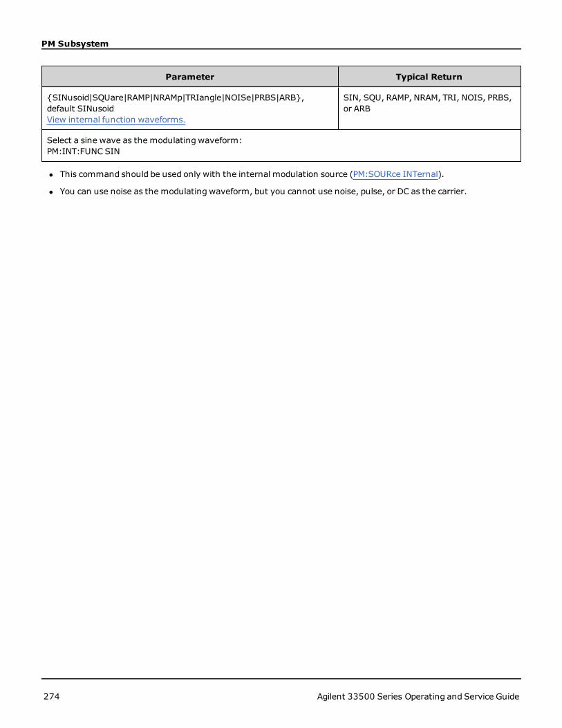
PM Subsystem
Parameter Typical Return
{SINusoid|SQUare|RAMP|NRAMp|TRIangle|NOISe|PRBS|ARB},default SINusoidView internal function waveforms.
SIN, SQU, RAMP, NRAM, TRI, NOIS, PRBS,or ARB
Select a sine wave as the modulating waveform:PM:INT:FUNC SIN
l This command should be used only with the internal modulation source (PM:SOURce INTernal).
l You can use noise as the modulating waveform, but you cannot use noise, pulse, or DC as the carrier.
274 Agilent 33500 Series Operating and Service Guide

[SOURce[1|2]:]AM:SOURce {INTernal|EXTernal|CH1|CH2}[SOURce[1|2]:]AM:SOURce?[SOURce
[SOURce[1|2]:]AM:SOURce {INTernal|EXTernal|CH1|CH2}[SOURce[1|2]:]AM:SOURce?
[SOURce[1|2]:]BPSK:SOURce {INTernal|EXTernal}[SOURce[1|2]:]BPSK:SOURce
[SOURce[1|2]:]FM:SOURce {INTernal|EXTernal|CH1|CH2}[SOURce[1|2]:]FM:SOURce
[SOURce[1|2]:]FSKey:SOURce {INTernal|EXTernal}[SOURce[1|2]:]FSKey:SOURce
[SOURce[1|2]:]PM:SOURce {INTernal|EXTernal|CH1|CH2}[SOURce[1|2]:]PM:SOURce
[SOURce[1|2]:]PWM:SOURce {INTernal|EXTernal|CH1|CH2}[SOURce[1|2]:]PWM:SOURce?Select the source of the modulating signal.
Parameter Typical Return
{INTernal|EXTernal|CH1|CH2}, default INTernal. BPSK and FSKey can-not accept CH1 or CH2
INT, EXT, CH1, or CH2
Select external modulation source:AM:SOUR EXT (could also substitute FM, BPSK, FSK, PM, or PWM for AM)
Remarks
l If you select EXTernal, the carrier waveform is modulated with an external waveform. Specifically:
l AM:The modulation depth is controlled by the ±5 V signal level on the rear-panelModulation In connector.For example, if modulation depth (AM[:DEPTh]) is 100%, then when the modulating signal is at +5 V, the out-put will be at the maximum amplitude. Similarly, a -5 Vmodulating signal produces output at minimum ampli-tude.
l FM:If you select the Externalmodulating source, the deviation is controlled by the ±5 V signal level on therear-panelModulation In connector.For example, if the frequency deviation is 100 kHz, then a +5 V signallevel corresponds to a 100 kHz increase in frequency.Lower external signal levels produce less deviation andnegative signal levels reduce the frequency below the carrier frequency.
l PM:With the External modulating source, deviation is controlled by the ±5 V signal level on the rear-panelModulation In connector. For example, if you have set the frequency deviation to 180 degrees, then a +5 Vsignal level corresponds to a +180 degree phase deviation. Lower external signal levels produce less deviation,and negative signal levels produce negative deviation.
Agilent 33500 Series Operating and Service Guide 275

[SOURce[1|2]:]AM:SOURce {INTernal|EXTernal|CH1|CH2}[SOURce[1|2]:]AM:SOURce?[SOURce
l Pulse as Selected Function: The pulse width or pulse duty cycle deviation is controlled by the ±5 V signallevel present on the rear-panelModulation In connector. For example, if you have set the pulse width devi-ation to 50 μs using the PWM:DEViation command, then a +5 V signal level corresponds to a 50 μs widthincrease. Lower external signal levels produce less deviation.
l With EXTernal source, the output phase (BPSK) or frequency (FSK) is determined by the signal level on the rear-panel Ext Trig connector. When a logic low is present, the carrier phase or carrier frequency is output. When alogic high is present, the phase shifted phase or hop frequency is output.
l The maximum external BPSK rate is 1 MHz, and the maximum FSK rate is 1 MHz.
l Note: the connector used for externally-controlled BPSK or FSK waveforms (Trig In) is not the same connectorthat is used for externally-modulated AM, FM, PM, and PWMwaveforms (Modulation In). When used for BPSK orFSK, the Trig In connector does not have adjustable edge polarity and is not affected by the TRIGger[1|2]:SLOPecommand.
l With INTernal source, the rate at which output phase (BPSK) or frequency (FSKey) "shifts" between the carrierphase or frequency and the alternate phase or frequency is determined by the BPSK rate (BPSK:INTernal:RATE) orFSK rate (FSKey:INTernal:RATE).
l A channel may not be its own modulation source.
See Also
AM Subsystem
BPSK Subsystem
FM Subsystem
FSKey Subsystem
PM Subsystem
PWM Subsystem
276 Agilent 33500 Series Operating and Service Guide

[SOURce[1|2]:]AM:STATe {ON|1|OFF|0}[SOURce[1|2]:]AM:STATe?[SOURce[1|2]:]BPSK:STATe
[SOURce[1|2]:]AM:STATe {ON|1|OFF|0}[SOURce[1|2]:]AM:STATe?
[SOURce[1|2]:]BPSK:STATe {ON|1|OFF|0}[SOURce[1|2]:]BPSK:STATe
[SOURce[1|2]:]FM:STATe {ON|1|OFF|0}[SOURce[1|2]:]FM:STATe
[SOURce[1|2]:]FSKey:STATe {ON|1|OFF|0}[SOURce[1|2]:]FSKey:STATe
[SOURce[1|2]:]PM:STATe {ON|1|OFF|0}[SOURce[1|2]:]PM:STATe
[SOURce[1|2]:]PWM:STATe {ON|1|OFF|0}[SOURce[1|2]:]PWM:STATe?Enables or disables modulation.
Parameter Typical Return
{ON|1|OFF|0}, default OFF 0 (OFF) or 1 (ON)
Enable AM (could also substitute FM, BPSK, FSK, PM, or PWM):AM:STAT ON
l To avoidmultiple waveform changes, enable modulation after configuring the other modulation parameters.
l Only one modulation modemay be enabled at a time.
l The instrument will not enable modulation with sweep or burst enabled. When you enable modulation, the sweepor burst mode is turned off.
l PWM is allowed only when pulse is the selected function.
See Also
AM Subsystem
BPSK Subsystem
FM Subsystem
FSKey Subsystem
PM Subsystem
PWM Subsystem
Agilent 33500 Series Operating and Service Guide 277

PWM Subsystem
PWM SubsystemThe PWM subsystem allows you to perform pulse width modulation (PWM) on a pulse waveform.
Example
This summarizes the steps required to generate a PWMwaveform.
1. Configure carrier waveform: Use FUNCtion, FREQuency, VOLTage, and VOLTage:OFFSet to specify the carrierwaveform's function, frequency, amplitude, and offset.
2. Select modulation source (internal, external, CH1, or CH2): PWM:SOURce. For an external modulationsource, skip steps 3 and 4.
3. Select modulating waveform: PWM:INTernal:FUNCtion
4. Set modulating frequency: PWM:INTernal:FREQuency
5. Set pulse width or duty cycle deviation:PWM:DEViation or PWM:DEViation:DCYCle
6. Enable PWM: PWM:STATe:ON
The following code produces the oscilloscope image shown below.
FUNCtion PULS
FREQuency +5000.0
VOLTage +1.0
VOLTage:OFFS +0.0
PWM:DEViation +5.0E-05
PWM:DEViation:DCYCle +25.0
PWM:INTernal:FREQuency +1000.0
PWM:INTernal:FUNCtion RAMP
PWM:STATe 1
OUTPut1 1
[SOURce[1|2]:]PWM:DEViation {<deviation>|MINimum|MAXimum}[SOURce[1|2]:]PWM:DEViation? [{MINimum|MAXimum}]
Sets pulse width deviation; the ± variation in width (in seconds) from the pulse width of the carrier pulse waveform.
278 Agilent 33500 Series Operating and Service Guide

PWM Subsystem
Parameter Typical Return
0 to 1000 (seconds); default 10 μs +1.000000000000000E+00
Set pulse width deviation to 1 s:PWM:DEV 1
Set pulse width deviation to 0 s:PWM:DEV MIN
l The deviation is a ± deviation, so if the pulse width is 10 ms and the deviation is 4 ms, the width can vary from 6 to14 ms.
l The pulse width deviation cannot exceed the current pulse width, and is also limited by the minimum pulse width(Wmin):
Width Deviation < Pulse Width – Wmin
and
Width Deviation < Period – Pulse Width – Wmin
l The pulse width deviation is limited by the current edge time setting.
Width Deviation < Pulse Width – (0.8 x Leading Edge Time) – (0.8 x Trailing Edge Time)
and
Width Deviation < Period – Pulse Width – (0.8 x Leading Edge Time) – (0.8 x Trailing Edge Time)
l If you select the External modulating source (PWM:SOURce EXTernal), the deviation is controlled by the ±5 V sig-nal level present on the rear-panelModulation In connector. For example, if you have set the width deviation to10 μs, then a +5 V signal level corresponds to a 10 μs deviation. Lower external signal levels produce less devi-ation. Negative signal levels produce negative deviation.
[SOURce[1|2]:]PWM:DEViation:DCYCle {<deviation_in_pct>|MINimum|MAXimum}[SOURce[1|2]:]PWM:DEViation:DCYCle? [{MINimum|MAXimum}]
Sets duty cycle deviation in percent of period. This is the peak variation in duty cycle from the underlying pulse wave-form. For example, if duty cycle is 10% and duty cycle deviation is 5%, the duty cycle of the modulated waveform willvary from 5% to 15%.
Parameter Typical Return
Duty cycle in percent of period, from 0 to 99.9; default approximately 1 percent +5.000000000000000E+00
Set pulse width deviation to 5%:PWM:DEV:DCYC 5
l Duty cycle deviation cannot exceed pulse duty cycle.
l Duty cycle deviation also limited by minimum pulse width (Wmin):
Duty Cycle Deviation < Duty Cycle – 100 x Wmin ÷ Period
and
Duty Cycle Deviation < 100 – Duty Cycle – 100 x Wmin ÷ Period
where Wmin = 16 ns.
l Duty cycle deviation limited by edge time.
Agilent 33500 Series Operating and Service Guide 279

PWM Subsystem
Duty Cycle Dev < Duty Cycle – (80 x Leading Edge Time) ÷ Period – (80 x Trailing Edge Time) ÷ Period
and
Duty Cycle Dev < 100 – Duty Cycle – (80 x Leading Edge Time) ÷ Period – (80 x Trailing Edge Time) ÷Period
l With PWM:SOURce EXTernal, deviation is controlled by the ±5 V signal level on rear-panelModulation In con-nector. For example, with duty cycle deviation of 5 percent, a +5 V signal level corresponds to 5% deviation, anadditional 5% of period added to the pulse duty cycle. Lower external signal levels produce less deviation, and neg-ative signal levels reduce the duty cycle.
[SOURce[1|2]:]PWM:INTernal:FREQuency {<frequency>|MAXimum|MINimum}[SOURce[1|2]:]PWM:INTernal:FREQuency? [{MAXimum|MINimum}]
Selects frequency at which output pulse width shifts through its pulse width deviation. The waveform used as the mod-ulating source will operate at that frequency, within frequency limits of that waveform.
Parameter Typical Return
1 μHz to the maximum allowed for the internal function. Default 10 Hz +1.000000000000000E+02
Set internal PWM frequency to 100 Hz:PWM:INT:FREQ 100
l When you select an arbitrary waveform as the modulating source, the frequency changes to the frequency of thearbitrary waveform, which is based on the sample rate and the number of points in the arbitrary waveform.
l When using an arbitrary waveform for the modulating source, changing this parameter also changes the cachedmetadata representing the aribtrary waveform's sample rate. You can also change the modulating frequency of anarbitrary waveform with FUNCtion:ARBitrary:FREQuency, FUNCtion:ARBitrary:PERiod, and FUNC-tion:ARBitrary:SRATe. These commands and the modulation frequency command are directly coupled in order tokeep the arbitrary waveform behaving exactly as it was last played. If you later turn modulation off and select thatsame arbitrary waveform as the current function, its sample rate (and corresponding frequency based upon thenumber of points) will be the same as it was when played as the modulation source.
l If the internal function is TRIangle, UpRamp, or DnRamp, the maximum frequency limited to 200 kHz. If the inter-nal function is PRBS, the frequency refers to bit rate and is limited to 50 Mbps.
l This command should be used only with the internal modulation source (PWM:SOURce INTernal).
[SOURce[1|2]:]PWM:INTernal:FUNCtion <function>[SOURce[1|2]:]PWM:INTernal:FUNCtion?
Selects shape of the internal modulating waveform.
Parameter Typical Return
{SINusoid|SQUare|RAMP|NRAMp|TRIangle|NOISe|PRBS|ARB},default SINusoidView internal function waveforms.
SIN, SQU, RAMP, NRAM, TRI, NOIS, PRBS,or ARB
Select a sine wave as the modulating waveform shape:PWM:INT:FUNC SIN
l This command should be used only with the internal modulation source (PWM:SOURce INTernal).
280 Agilent 33500 Series Operating and Service Guide

[SOURce[1|2]:]AM:SOURce {INTernal|EXTernal|CH1|CH2}[SOURce[1|2]:]AM:SOURce?[SOURce
[SOURce[1|2]:]AM:SOURce {INTernal|EXTernal|CH1|CH2}[SOURce[1|2]:]AM:SOURce?
[SOURce[1|2]:]BPSK:SOURce {INTernal|EXTernal}[SOURce[1|2]:]BPSK:SOURce
[SOURce[1|2]:]FM:SOURce {INTernal|EXTernal|CH1|CH2}[SOURce[1|2]:]FM:SOURce
[SOURce[1|2]:]FSKey:SOURce {INTernal|EXTernal}[SOURce[1|2]:]FSKey:SOURce
[SOURce[1|2]:]PM:SOURce {INTernal|EXTernal|CH1|CH2}[SOURce[1|2]:]PM:SOURce
[SOURce[1|2]:]PWM:SOURce {INTernal|EXTernal|CH1|CH2}[SOURce[1|2]:]PWM:SOURce?Select the source of the modulating signal.
Parameter Typical Return
{INTernal|EXTernal|CH1|CH2}, default INTernal. BPSK and FSKey can-not accept CH1 or CH2
INT, EXT, CH1, or CH2
Select external modulation source:AM:SOUR EXT (could also substitute FM, BPSK, FSK, PM, or PWM for AM)
Remarks
l If you select EXTernal, the carrier waveform is modulated with an external waveform. Specifically:
l AM:The modulation depth is controlled by the ±5 V signal level on the rear-panelModulation In connector.For example, if modulation depth (AM[:DEPTh]) is 100%, then when the modulating signal is at +5 V, the out-put will be at the maximum amplitude. Similarly, a -5 Vmodulating signal produces output at minimum ampli-tude.
l FM:If you select the Externalmodulating source, the deviation is controlled by the ±5 V signal level on therear-panelModulation In connector.For example, if the frequency deviation is 100 kHz, then a +5 V signallevel corresponds to a 100 kHz increase in frequency.Lower external signal levels produce less deviation andnegative signal levels reduce the frequency below the carrier frequency.
l PM:With the External modulating source, deviation is controlled by the ±5 V signal level on the rear-panelModulation In connector. For example, if you have set the frequency deviation to 180 degrees, then a +5 Vsignal level corresponds to a +180 degree phase deviation. Lower external signal levels produce less deviation,and negative signal levels produce negative deviation.
Agilent 33500 Series Operating and Service Guide 281

[SOURce[1|2]:]AM:SOURce {INTernal|EXTernal|CH1|CH2}[SOURce[1|2]:]AM:SOURce?[SOURce
l Pulse as Selected Function: The pulse width or pulse duty cycle deviation is controlled by the ±5 V signallevel present on the rear-panelModulation In connector. For example, if you have set the pulse width devi-ation to 50 μs using the PWM:DEViation command, then a +5 V signal level corresponds to a 50 μs widthincrease. Lower external signal levels produce less deviation.
l With EXTernal source, the output phase (BPSK) or frequency (FSK) is determined by the signal level on the rear-panel Ext Trig connector. When a logic low is present, the carrier phase or carrier frequency is output. When alogic high is present, the phase shifted phase or hop frequency is output.
l The maximum external BPSK rate is 1 MHz, and the maximum FSK rate is 1 MHz.
l Note: the connector used for externally-controlled BPSK or FSK waveforms (Trig In) is not the same connectorthat is used for externally-modulated AM, FM, PM, and PWMwaveforms (Modulation In). When used for BPSK orFSK, the Trig In connector does not have adjustable edge polarity and is not affected by the TRIGger[1|2]:SLOPecommand.
l With INTernal source, the rate at which output phase (BPSK) or frequency (FSKey) "shifts" between the carrierphase or frequency and the alternate phase or frequency is determined by the BPSK rate (BPSK:INTernal:RATE) orFSK rate (FSKey:INTernal:RATE).
l A channel may not be its own modulation source.
See Also
AM Subsystem
BPSK Subsystem
FM Subsystem
FSKey Subsystem
PM Subsystem
PWM Subsystem
282 Agilent 33500 Series Operating and Service Guide

[SOURce[1|2]:]AM:STATe {ON|1|OFF|0}[SOURce[1|2]:]AM:STATe?[SOURce[1|2]:]BPSK:STATe
[SOURce[1|2]:]AM:STATe {ON|1|OFF|0}[SOURce[1|2]:]AM:STATe?
[SOURce[1|2]:]BPSK:STATe {ON|1|OFF|0}[SOURce[1|2]:]BPSK:STATe
[SOURce[1|2]:]FM:STATe {ON|1|OFF|0}[SOURce[1|2]:]FM:STATe
[SOURce[1|2]:]FSKey:STATe {ON|1|OFF|0}[SOURce[1|2]:]FSKey:STATe
[SOURce[1|2]:]PM:STATe {ON|1|OFF|0}[SOURce[1|2]:]PM:STATe
[SOURce[1|2]:]PWM:STATe {ON|1|OFF|0}[SOURce[1|2]:]PWM:STATe?Enables or disables modulation.
Parameter Typical Return
{ON|1|OFF|0}, default OFF 0 (OFF) or 1 (ON)
Enable AM (could also substitute FM, BPSK, FSK, PM, or PWM):AM:STAT ON
l To avoidmultiple waveform changes, enable modulation after configuring the other modulation parameters.
l Only one modulation modemay be enabled at a time.
l The instrument will not enable modulation with sweep or burst enabled. When you enable modulation, the sweepor burst mode is turned off.
l PWM is allowed only when pulse is the selected function.
See Also
AM Subsystem
BPSK Subsystem
FM Subsystem
FSKey Subsystem
PM Subsystem
PWM Subsystem
Agilent 33500 Series Operating and Service Guide 283

RATE Subsystem
RATE SubsystemThe RATE subsystem allows you to couple the outputs' sample rates on a two-channel instrument by specifying the fol-lowing items:
l RATE:COUPle[:STATe] - whether coupling is used
l RATE:COUPle:MODE - whether coupling is done as a ratio or an offset
l RATE:COUPle:OFFSet - offset usedwhen the coupling is done as an offset
l RATE:COUPle:RATio - ratio usedwhen the coupling is done as a ratio
[SOURce[1|2]:]RATE:COUPle[:STATe] {ON|1|OFF|0}[SOURce[1|2]:]RATE:COUPle[:STATe]?
Enables or disables sample rate coupling between channels, or allows one-time copying of one channel's sample rateinto the other channel.
Parameter Typical Return
{ON|1|OFF|0}, default OFF 0 (OFF) or 1 (ON)
Turn on sample rate coupled state:RATE:COUP ON
l The ON value starts sample rate coupling in the mode specified by RATE:COUPle:MODE.
l If the current offset or ratio, combinedwith the current sample rate settings, would cause either sample rate toexceed instrument specifications, the instrument will generate an error and the exceeded sample rate will clip atits maximum or minimum value.
l If settingmode to RATIO and setting RATIO to 1.0 still exceeds the specifications of either channel, an error mes-sage will be generated and the RATE:COUPle[:STATe] will not be turned ON.
l Both channels must be configured for FUNCtion ARB in order to enable sample rate coupling.
[SOURce[1|2]:]RATE:COUPle:MODE {OFFSet|RATio}[SOURce[1|2]:]RATE:COUPle:MODE?
Sets type of sample rate coupling to either a constant sample rate offset (OFFSet) or a constant ratio (RATio) betweenthe channels' sample rates.
Parameter Typical Return
{OFFSet|RATio}, default RATio OFFS or RAT
Set the sample rate couplingmode to OFFSet.RATE:COUP:MODE OFFSet
l The default RATio is 1.
l The default sample rate coupling is OFF.
l The SOURce[1|2] keyword is ignored; the setting applies to both channels.
284 Agilent 33500 Series Operating and Service Guide

RATE Subsystem
[SOURce[1|2]:]RATE:COUPle:OFFSet <sample_rate>[SOURce[1|2]:]RATE:COUPle:OFFSet?
Sets sample rate offset when a two-channel instrument is in sample rate coupledmode OFFSet.
Parameter Typical Return
Valid values depend on FUNCtion:ARBitrary:FILTer setting. For NORMal and STEP,the range is between ± 250 MSa/s . For OFF, the range is between ±62.5 MSa/s. Ineither case, default is 0.
+8.000000000000000E+02
Set sample rate offset of channel 2 to 10.3 kSa/s higher than sample rate of channel 1.RATE:COUPle:OFFSet 10300
Sets the sample rate offset of channel 1 to 45 kSa/s below the sample rate of channel 2.SOUR2:RATE:COUP:OFFS -45000
l When specifying OFFSet or RATio, the SOURce channel specified in the command (SOURce1 or SOURce2) is usedas the reference channel and the offset or ratio is applied to the other channel. For example, suppose the functiongenerator is in RATE:COUPle[:STATe] ON and RATE:COUPle:MODE is set to OFFSet. Furthermore, suppose channel1 is currently operating at 2 kSa/s, and channel 2 is at 10 kSa/s. The commandSOURce1:RATE:-COUPle:OFFSet 2.5 causes Channel 1 to remain at 2 Sa/s, and Channel 2 to be set to 4.5 Sa/s. As the samplerate of either channel changes, the other channel's sample rate changes to maintain the specified coupling.
l If the sample rate coupling would cause either channel to exceed instrument sample rate specifications for thepresent functions, the commandwill result in an error, and the sample rate will be set to its maximum or mini-mum limit for the particular channel.
[SOURce[1|2]:]RATe:COUPle:RATio <ratio>[SOURce[1|2]:]RATe:COUPle:RATio?
Sets offset ratio between channel sample rates when a two-channel instrument is in sample rate coupledmode RATio.
Parameter Typical Return
0.001 to 1000, default 1 +7.500000000000000E-1
Set channel 2's sample rate to twice that of channel 1.SOUR1:RATE:COUP:RATio 2
Set channel 1's sample rate to 3.14 times that of channel 2.SOUR2:RATE:COUPle:RAT 3.14
l When specifying OFFSet or RATio, the SOURce channel specified in the command (SOURce1 or SOURce2) is usedas the reference channel and the offset or ratio is applied to the other channel. For example, suppose the functiongenerator is coupled in RATio mode. Furthermore, suppose channel 1 is currently operating at 2 kSa/s, and chan-nel 2 is at 10 kSa/s.
The commandSOURce1:RATe:COUPle:RATio 2.5 causes Channel 1 to remain at 2 kSa/s, and Channel 2 to beset to 5 kSa/s. As the sample rate of either channel changes, the other channel's sample rate changes to maintainthe specified coupling.
Agilent 33500 Series Operating and Service Guide 285

RATE Subsystem
l If the sample rate coupling would cause either channel to exceed instrument sample rate specifications for thepresent functions, the commandwill result in an error, and the sample rate will be set to its maximum or mini-mum limit for the particular channel.
286 Agilent 33500 Series Operating and Service Guide

ROSCillator Subsystem
ROSCillator SubsystemThe ROSCillator subsystem controls use of the 10 MHz reference oscillator and external reference oscillator input. Thereference oscillator is the primary clock for all waveform synthesis. All waveforms are phase-locked to the referenceoscillator, which therefore controls output signal frequency and phase.
l ROSCillator:SOURce - selects internal or external reference oscillator source
l ROSCillator:SOURce:AUTO - disables or enables automatic selection of reference oscillator signal source
l ROSCillator:SOURce:CURRent? - returns INT or EXT to indicate current reference oscillator source
ROSC:SOURce sets ROSCillator:SOURce:AUTO to OFF, and ROSCillator:SOURce:AUTOON overrides ROSC:SOURce. Themore recent command (of these two) takes priority.
ROSCillator:SOURce:AUTOON uses the instrument's internal oscillator as the reference oscillator. This may be eitherstandard Temperature Compensated Crystal Oscillator (TCXO) or the optional Ovenized Crystal Oscillator (OCXO).
See *OPT? for details on determining whether OCXO is installed. If an external 10 MHz reference signal is on the rear-panel 10 MHz In connector, the instrument uses the external signal. An icon also appears at the top right corner ofthe display to indicate the reference source change.
ROSCillator:SOURce {INTernal|EXTernal}ROSCillator:SOURce?
Selects the source for the reference oscillator used as the frequency/phase reference for signals generated by theinstrument.
Parameter Typical Return
{INTernal|EXTernal}, default INT INT or EXT
Use the external reference oscillator source:ROSC:SOUR EXT
l EXTernal:instrument uses signal on the rear-panel 10 MHz In connector as reference, and generates an error ifthis signal is absent or the instrument cannot lock to it. In such error cases, instrument output continues, but thefrequency will be unstable.
l INTernal: instrument uses the internal reference oscillator and ignores the signal at the 10 MHz In connector.
ROSCillator:SOURce:AUTO {ON|OFF}ROSCillator:SOURce:AUTO?
Disables or enables automatic selection of the reference oscillator.
Parameter Typical Return
{ON|OFF}, default ON ON or OFF
Select reference source automatically:ROSC:SOUR:AUTOON
Agilent 33500 Series Operating and Service Guide 287

ROSCillator Subsystem
l ON: the instrument preferentially selects a 10 MHz signal from the rear-panel 10 MHz In connector.
l OFF: the instrument selects the reference oscillator based on the ROSC:SOURce setting.
ROSCillator:SOURce:CURRent?
Indicates which reference oscillator signal is currently in use when ROSC:SOURce:AUTO is ON.
Parameter Typical Return
(none) INT (internal) or EXT (10 MHz connector on rear panel)
Determine reference signal source:ROSC:SOUR:CURR?
l INT refers to the basic internal TCXO or the optional ovenized OCXO oscillator, whichever is installed.
288 Agilent 33500 Series Operating and Service Guide

SOURce Subsystem
SOURce SubsystemThe SOURce keyword is optional in many commands that set parameters for a source or output channel.
Example
The SOURce keyword and the channel number are optional in the [SOURce[1|2]:]AM[:DEPTh]? query, and if it isomitted, the source defaults to channel 1. The following table shows how various forms of the query are interpreted.
Parameter Typical Return
AM:DEPTh? returns the modulation depth of channel 1
SOUR1:AM:DEPTh? returns the modulation depth of channel 1
SOUR2:AM:DEPTh? returns the modulation depth of channel 2 (two-channel instruments only)
Subsystems Using the Optional SOURce Keyword
Because SOURce subsystem commands are often usedwithout the SOURce keyword, these commands are listed bytheir individual subsystems, below:
AM
APPLy
BPSK
BURSt
DATA
FM
FREQuency
FSKey
FUNCtion
LIST
MARKer
PHASe
PM
PWM
ROSCillator
SUM
SWEep
VOLTage
Agilent 33500 Series Operating and Service Guide 289

SOURce Subsystem
Commands Using the Optional SOURce Keyword
The following commands, which are not part of any subsystem, also have the optional SOURce keyword:
COMBine:FEED
TRACk
290 Agilent 33500 Series Operating and Service Guide

STATus Subsystem Introduction
STATus Subsystem IntroductionThe instrument's SCPI status system records various instrument conditions and states in several register groups.
In this subsystem, an event is something that occurred, even though it may not still be occurring. A condition is some-thing that is currently present. A condition will appear in the event register, but the event register is read destructive; itis cleared (set to 0) when read.
The STATus commandsmanipulate bits in two of the enable registers. You can:
l Enable bits in theQuestionable Data enable register (STATus:QUEStionable:ENABle).
l Enable bits in theOperation enable register (STATus:OPERation:ENABle). Query: STATus:OPERation:ENABle?
l Clear all bits in theQuestionable Data enable register and the Standard Operation enable register (STAT-us:PRESet).
The STATus queries accesses information about the status bits in theQuestionable Data registers, including:
l The binary-weighted sum of all bits enabled in the Questionable Data condition register ( STAT-us:QUEStionable:CONDition?)
l The binary-weighted sum of all bits enabled in the Questionable Data event register (STATus:QUEStionable[:EVENt]?)
l The binary-weighted sum of all bits enabled in the Questionable Data enable register (STAT-us:QUEStionable:ENABle?).
The STATus queries also allow you to access information about the status bits in theOperation registers, including:
l The binary-weighted sum of all bits enabled in the Operation condition register (STATus:OPERation:CONDition?).
l The binary-weighted sum of all bits enabled in the Operation event register (STATus:OPERation:EVENt?).
Standard Operation Register Group
The following table describes the Standard Operation Register group.
Bit Bit Name DecimalValue
Definition
0 Calibrating 1 The instrument is performing a calibration.
1 Self-test 2 A self-test is running.
2 (Reserved) 4 (Reserved for future use)
3 Channel 1 Initiated 8 Channel is initiated and outputting the desired wave-form. In INIT[1|2]:CONTOFF, this bit is set after receiv-ing an INIT and not cleared until channel goes to IDLE( trigger count satisfied and not busy.) This bit is 0 if thechannel is in INIT[1|2]:CONTONmode.
4 Channel 2 Initiated 16
Agilent 33500 Series Operating and Service Guide 291

STATus Subsystem Introduction
5 Waiting for Trigger,Channel 1
32 Instrument is waiting for a trigger. In INIT[1|2]:CONTOFF, this bit is set after receiving an INIT andwhile wait-ing for a trigger. It is cleared after receiving the trigger.This bit is 0 if the channel is in INIT[1|2]:CONTONmode.
6 Waiting for Trigger,Channel 2
64
7 (Reserved) 128 (Reserved for future use)
8 ConfigurationChanged Event
256 This bit is always 0 in the condition register, as itreflects an event, not a condition.
9 (Reserved) 512 (Reserved for future use)
10 Instrument Locked 1024 If a remote interface (USB or LAN) has a lock (SYS-Tem:LOCK:REQuest?), this bit will be set. When aremote interface releases the lock (SYS-Tem:LOCK:RELease), this bit will be cleared.
11 (Reserved) 2048 (Reserved for future use)
12 (Reserved) 4096 (Reserved for future use)
13 Global Error 8192 This is set if any remote interface has an error in itserror queue, and cleared otherwise.
14-15
(Reserved) 16,384 -32,768
(Reserved for future use)
Questionable Data Register Group
The following table describes the Questionable Data Register group.
Bit Bit Name DecimalValue
Definition
0 Channel 1 Volt-age Overload
1 Voltage overload on channel 1 output connector. The out-put has been disabled.
1 Channel 2 Volt-age Overload
2 Voltage overload on channel 2 output connector. The out-put has been disabled.
2 (Reserved) 4 (Reserved for future use)
3 (Reserved) 8 (Reserved for future use)
4 (Reserved) 16 (Reserved for future use)
5 Loop Unlocked 32 Function generator has lost phase lock. Frequency accuracywill be affected.
6 (Reserved) 64 (Reserved for future use)
292 Agilent 33500 Series Operating and Service Guide

STATus Subsystem Introduction
7 (Reserved) 128 (Reserved for future use)
8 Calibration Error 256 Error occurred during calibration, calibration is unsecured,or calibration memory has been lost
9 External Ref-erence
512 External timebase has been detected.
10-15 (Reserved) 1024 -32,768
(Reserved for future use)
STATus:OPERation:CONDition?
Queries the condition register for the Standard Operation Register group. Register is read-only; bits not cleared whenread.
Parameter Typical Return
(none) +32
Agilent 33500 Series Operating and Service Guide 293
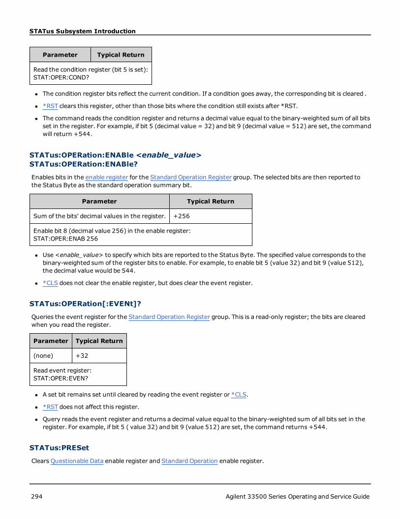
STATus Subsystem Introduction
Parameter Typical Return
Read the condition register (bit 5 is set):STAT:OPER:COND?
l The condition register bits reflect the current condition. If a condition goes away, the corresponding bit is cleared .
l *RST clears this register, other than those bits where the condition still exists after *RST.
l The command reads the condition register and returns a decimal value equal to the binary-weighted sum of all bitsset in the register. For example, if bit 5 (decimal value = 32) and bit 9 (decimal value = 512) are set, the commandwill return +544.
STATus:OPERation:ENABle <enable_value>STATus:OPERation:ENABle?
Enables bits in the enable register for the Standard Operation Register group. The selected bits are then reported tothe Status Byte as the standard operation summary bit.
Parameter Typical Return
Sum of the bits' decimal values in the register. +256
Enable bit 8 (decimal value 256) in the enable register:STAT:OPER:ENAB 256
l Use <enable_value> to specify which bits are reported to the Status Byte. The specified value corresponds to thebinary-weighted sum of the register bits to enable. For example, to enable bit 5 (value 32) and bit 9 (value 512),the decimal value would be 544.
l *CLS does not clear the enable register, but does clear the event register.
STATus:OPERation[:EVENt]?
Queries the event register for the Standard Operation Register group. This is a read-only register; the bits are clearedwhen you read the register.
Parameter Typical Return
(none) +32
Read event register:STAT:OPER:EVEN?
l A set bit remains set until cleared by reading the event register or *CLS.
l *RST does not affect this register.
l Query reads the event register and returns a decimal value equal to the binary-weighted sum of all bits set in theregister. For example, if bit 5 ( value 32) and bit 9 (value 512) are set, the command returns +544.
STATus:PRESet
Clears Questionable Data enable register and Standard Operation enable register.
294 Agilent 33500 Series Operating and Service Guide

STATus Subsystem Introduction
Parameter Typical Return
(none) (none)
Clear enable register bits:STAT:PRES
STATus:QUEStionable:CONDition?
Queries the condition register for the Questionable Data Register group.
Parameter Typical Return
(none) +512
Read the condition register (bit 9 is set):STAT:QUES:COND?
l The Questionable Data register group provides information about the instrument's quality or integrity.
l Any or all conditions can be reported to the Questionable Data summary bit through the enable register.
l Register is read-only; bits not cleared when read.
l The condition register bits reflect the current condition. If a condition goes away, the corresponding bit is cleared.
l *RST clears the condition register.
l The query reads the condition register and returns a decimal value equal to the binary-weighted sum of all bits setin the register. For example, if bit 12 (decimal value = 4096) is set, the query returns "+4096".
STATus:QUEStionable:ENABle <enable_value>STATus:QUEStionable:ENABle?
Enables bits in the enable register for the Questionable Data Register group. The selected bits are then reported to theStatus Byte.
Parameter Typical Return
Decimal value equal to the sum of the bit decimal values in the register. +512
Enable bit 9 (value 512) in the enable register:STAT:QUES:ENAB 512
l Use <enable_value> to specify which bits are reported to the Status Byte. The specified value corresponds to thebinary-weighted sum of the register bits to enable. For example, to enable bit 5 (value 32) and bit 9 (value 512),the decimal value would be 544.
l Enable register cleared by:
l STATus:Questionable:ENABle 0
l STATus:PRESet
l Power cycle
l *CLS does not clear enable register but it does clear event register.
Agilent 33500 Series Operating and Service Guide 295

STATus Subsystem Introduction
l *RST does not affect this register.
l The Query reads the enable register and returns a decimal value equal to the binary-weighted sum of all bits set inthe register.ter. For example, if bit 0 (value 1) and bit 1 ( value 2) are enabled, the query returns +3.
STATus:QUEStionable[:EVENt]?
Queries the event register for the Questionable Data Register group. This is a read-only register; the bits are clearedwhen you read the register.
Parameter Typical Return
(none) +512
Read the event register (bit 9 set):STAT:QUES?
l Once a bit is set, it remains set until cleared by this query or *CLS.
l *RST, STATus:PRESet, and *PSC have no effect on this register.
l Query reads the event register and returns a decimal value equal to the binary-weighted sum of all bits set in theregister. For example, if bit 1 (value 2) and bit 9 ( value 512) are set, the query returns "+514".
296 Agilent 33500 Series Operating and Service Guide

SUM Subsystem Introduction
SUM Subsystem IntroductionThe SUM subsystem adds amodulation source signal to a channel's primary signal. This allows you to generate a two-tone signal on one channel, or to add noise to a primary signal. The SUM function uses the same secondary sources asused by the modulation subsystems.
Only one modulation or SUM function may be active on a channel at a time, so you cannot add noise to an FM signalusing only one channel. For this operation, use COMBine:FEED, which combines both channels of a two-channel instru-ment into one channel output connector.
When signals are SUMmed:
l Their peak amplitude may not exceed the instrument's output rating.
l No other internal or external modulation is possible on that channel.
You can synchronize the phase between the primary signal and the SUM signal by sending SOURce[1|2]:PHA-Se:SYNChronize after setting the functions for the primary signal and the SUM signal. Otherwise, the phase betweenthe two signals is arbitrary.
Example
To create a SUM waveform:
1. Configure carrier waveform: Use FUNCtion, FREQuency, VOLTage, and VOLTage:OFFSet to specify the carrierwaveform's function, frequency, amplitude, and offset.
2. Select the summing source: The instrument accepts an internal or external modulation source (EXT, Channel1, or Channel 2). Select the modulation source with SUM:SOURce. For an external modulation source, skip steps 3and 4.
3. Configure the summing waveform: Use FUNCtion, FREQuency, VOLTage, and VOLTage:OFFSet commands toconfigure the summingwaveform.
4. Set the amplitude percentage to sum:SUM:AMPLitude.
5. Enable SUM Modulation: SUM:STATe:ON.
6. If using the other channel of a two-channel instrument, synchronize the channels: PHASe:SY-NChronize.
The following code produces the oscilloscope image shown below.
SOURce1:FUNCtion RAMP
SOURce1:FREQuency +2000.0
SOURce1:VOLTage +1.0
SOURce1:VOLTage:OFFS +0.0
SOURce1:FUNCtion:RAMP:SYMMetry +50.0
SOURce2:FUNCtion SQU
SOURce2:FREQuency +4000.0
SOURce2:VOLTage +1.0
SOURce2:VOLTage:OFFS +0.0
SOURce1:SUM:AMPLitude +50.0
SOURce1:SUM:SOURce CH2
SOURce1:SUM:STATe 1
SOURce1:PHASe:SYNC
Agilent 33500 Series Operating and Service Guide 297

SUM Subsystem Introduction
OUTPut1 1
OUTPut2 1
[SOURce[1|2]:]SUM:AMPLitude <amplitude>[SOURce[1|2]:]SUM:AMPLitude? [{MINimum|MAXimum}]
Sets internal modulation depth (or "percent modulation") in percent.
Parameter Typical Return
Desired SUM signal amplitude in percent of carrier amplitude, from 0 to 100;default 0.1
+3.200000000000000E+00
Set the internal SUM signal amplitude to 1.0% of the signal amplitude:SUM:AMPL 1.0PHAS:SYNC
Set the internal sum signal amplitude on channel 2 to 0.15% of the signal amplitude:SOUR2:SUM:AMPL 0.15
l You can synchronize the phase between the primary signal and the SUM signal by sending SOURce[1|2]:PHA-Se:SYNChronize after setting the functions for the primary signal and the SUM signal. Otherwise, the phasebetween the two signals is arbitrary.
l Summed output cannot exceed±5 V peak output (into a 50 Ω load).
l If you select the External SUM source (SUM:SOURce EXTernal), the carrier waveform is added to the externalwaveform. The summing signal is the ±5 V signal level on the rear-panelModulation In connector. For example,if you have the carrier amplitude of a sine wave set to 4 Vpp and set the Sum Amplitude to 20% (resulting in amaximum sum contribution of 800 mVpp) using SUM:AMPLitude, then when the EXT signal is at +5 V, the addi-tive signal output will be at the maximum amplitude of 4.8 Vpp.When the modulating signal is at -5 V, the additivesignal will be at the minimum amplitude of -4.8 Vpp. Amodulation input of 0 V would result in a signal equal to thecarrier amplitude.
298 Agilent 33500 Series Operating and Service Guide

SUM Subsystem Introduction
[SOURce[1|2]:]SUM:INTernal:FREQuency {<frequency>|MINimum|MAXimum}[SOURce[1|2]:]SUM:INTernal:FREQuency? [{MINimum|MAXimum}]
Sets the frequency of the summingwaveform when internal sum source is selected (SUM:SOURce:INTernal). Themodulating source waveform operates at that frequency, within the frequency limits of that waveform.
Parameter Typical Return
1 μHz to the maximum allowed for the internal function. Default100 Hz
+1.000000000000000E-06
The following command sets the summing frequency to 10 kHz on Channel 2:SOUR2:SUM:INT:FREQ 10000
SOUR2:PHAS:SYNC The following command sets the summing frequency to 1 μHz on Channel 1:SUM:INT:FREQMINPHAS:SYNC
l You can synchronize the phase between the primary signal and the SUM signal by sending SOURce[1|2]:PHA-Se:SYNChronize after setting the functions for the primary signal and the SUM signal. Otherwise, the phasebetween the two signals is arbitrary.
l When you select an arbitrary waveform as the modulating source, the frequency changes to the frequency of thearbitrary waveform, which is based on the sample rate and the number of points in the arbitrary waveform.
l When using an arbitrary waveform for the modulating source, changing this parameter also changes the cachedmetadata representing the aribtrary waveform's sample rate. You can also change the modulating frequency of anarbitrary waveform with FUNCtion:ARBitrary:FREQuency, FUNCtion:ARBitrary:PERiod, and FUNC-tion:ARBitrary:SRATe. These commands and the modulation frequency command are directly coupled in order tokeep the arbitrary waveform behaving exactly as it was last played. If you later turn modulation off and select thatsame arbitrary waveform as the current function, its sample rate (and corresponding frequency based upon thenumber of points) will be the same as it was when played as the modulation source.
l If the internal function is TRIangle, UpRamp, or DnRamp, the maximum frequency limited to 200 kHz. If the inter-nal function is PRBS, the frequency refers to bit rate and is limited to 50 Mbps.
[SOURce[1|2]:]SUM:INTernal:FUNCtion <function>[SOURce[1|2]:]SUM:INTernal:FUNCtion?
Selects the summingwaveform (the waveform added to the primary waveform).
Parameter Typical Return
{SINusoid|SQUare|RAMP|NRAMp|TRIangle|NOISe|PRBS|ARB},default SINusoid
SIN, SQU, RAMP, NRAM, TRI, NOIS, PRBS,or ARB
Select a sine wave as the summingwaveform shape for channel 2:SOUR2:SUM:INT:FUNC SIN
l You can synchronize the phase between the primary signal and the SUM signal by sending SOURce[1|2]:PHA-Se:SYNChronize after setting the functions for the primary signal and the SUM signal. Otherwise, the phasebetween the two signals is arbitrary.
Agilent 33500 Series Operating and Service Guide 299

SUM Subsystem Introduction
l This command is applicable only with internal sum source (SUM:SOURce INTernal).
l You cannot use SUM when DC is the carrier.
l An arbitrary waveform may not simultaneously be a carrier and a sum waveform.
The following table shows which carriers can be associated with which internal functions.
Modulating Signal
Carrier Sine Square Tri / Ramp Noise PRBS Arb External
Sine • • • • • • •
Square/Pulse • • • • • • •
Triangle/Ramp • • • • • • •
Gaussian Noise • • • • • •
PRBS • • • • • •
Arbitrary • • • • • •
Sequenced Arbitrary • • • • • •
[SOURce[1|2]:]SUM:SOURce {INTernal|EXTernal}[SOURce[1|2]:]SUM:SOURce?
Selects source of summing signal.
Parameter Typical Return
{INTernal|EXTernal}, default INTernal INT or EXT
Set the sum source to EXTernal:SUM:SOUR EXT
l You can synchronize the phase between the primary signal and the SUM signal by sending SOURce[1|2]:PHA-Se:SYNChronize after setting the functions for the primary signal and the SUM signal. Otherwise, the phasebetween the two signals is arbitrary.
l SUM:SOURce EXTernal: carrier waveform is summedwith external waveform. The amplitude and polarity ofthe sum signal is determined by the ±5 V signal level on rear-panelModulation In connector. For example, if youhave set the SUM Amplitude to 2.0 Vpp using SUM:AMPLitude, then when EXT signal is at +5 V, the sum signal willbe at 2 Vpp.When the modulating signal is at -5 V, the sum signal will be at full amplitude and opposite polarity.
[SOURce[1|2]:]SUM:STATe {ON|1|OFF|0}[SOURce[1|2]:]SUM:STATe?
Disables or enables SUM function.
300 Agilent 33500 Series Operating and Service Guide
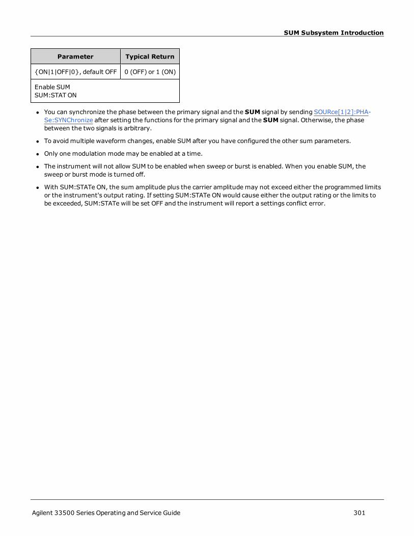
SUM Subsystem Introduction
Parameter Typical Return
{ON|1|OFF|0}, default OFF 0 (OFF) or 1 (ON)
Enable SUMSUM:STAT ON
l You can synchronize the phase between the primary signal and the SUM signal by sending SOURce[1|2]:PHA-Se:SYNChronize after setting the functions for the primary signal and the SUM signal. Otherwise, the phasebetween the two signals is arbitrary.
l To avoidmultiple waveform changes, enable SUM after you have configured the other sum parameters.
l Only one modulation modemay be enabled at a time.
l The instrument will not allow SUM to be enabled when sweep or burst is enabled. When you enable SUM, thesweep or burst mode is turned off.
l With SUM:STATe ON, the sum amplitude plus the carrier amplitude may not exceed either the programmed limitsor the instrument's output rating. If setting SUM:STATe ON would cause either the output rating or the limits tobe exceeded, SUM:STATe will be set OFF and the instrument will report a settings conflict error.
Agilent 33500 Series Operating and Service Guide 301

SWEep Subsystem Introduction
SWEep Subsystem IntroductionTo generate a frequency sweep:
1. Select the waveform shape, amplitude and offset: Use APPLy or the equivalent FUNCtion, FREQuency,VOLTage, and VOLTage:OFFSet commands to select the function, frequency, amplitude, and offset. You can selecta sine, square, ramp, pulse, or arbitrary waveform (noise, PRBS, and DC are not allowed).
2. Select sweep's frequency boundaries: FREQuency:STARt and FREQuency:STOP , or FREQuency:CENTer andFREQuency:SPAN
3. Select linear or logarithmic sweep mode: SWEep:SPACing
4. Set sweep time: SWEep:TIME
5. Set sweep hold and return times: SWEep:HTIMe and SWEep:RTIMe
6. Select sweep trigger source: TRIGger[1|2]:SOURce
7. Set the marker frequency (optional):MARKer:FREQuency
8. Enable sweep: SWEep:STATe ON
The following code produces the waveform shown below.
SOURce1:FUNCtion SINE
SOURce1:FREQuency +2.0E+03
SOURce1:FREQuency:STARt +2.0E+03
SOURce1:FREQuency:STOP +6.0E+03
SOURce1:VOLTage +1.0
SOURce1:VOLTage:OFFS +0.0
SOURce1:SWEep:TIME +5.0E-03
TRIGger1:SOURce IMM
SOURce1:FREQuency:MODE SWE
OUTPut1 1
302 Agilent 33500 Series Operating and Service Guide

SWEep Subsystem Introduction
[SOURce[1|2]:]SWEep:HTIMe {<hold_time> | MINimum | MAXimum}[SOURce[1|2]:]SWEep:HTIMe? [{MINimum|MAXimum}]
Sets number of seconds the sweep holds (pauses) at the stop frequency before returning to the start frequency.
Parameter Typical Return
0 to 3600, default 0 +3.400000000000000E+00
Set sweep hold time to 3.4 seconds:SWE:HTIM 3.4
[SOURce[1|2]:]SWEep:RTIMe {<return_time> | MINimum | MAXimum}[SOURce[1|2]:]SWEep:RTIMe? [ MINimum | MAXimum ]
Sets number of seconds the sweep takes to return from stop frequency to start frequency.
Parameter Typical Return
0 to 3600, default 0 +5.600000000000000E+00
Set sweep return time to 5.6 s:SWE:RTIM 5.6
l The return sweep is always a linear sweep, regardless of the setting of SWEep:SPACing.
[SOURce[1|2]:]SWEep:SPACing {LINear|LOGarithmic}[SOURce[1|2]:]SWEep:SPACing?
Selects linear or logarithmic spacing for sweep.
Parameter Typical Return
{LINear|LOGarithmic}, default LIN LIN or LOG
Set logarithmic sweep spacing:SWE:SPAC LIN
l LINear: output frequency varies linearly (from start frequency to stop frequency) during sweep.
l LOGarithmic: output frequency varies logarithmically (from start frequency to stop frequency) during sweep.
[SOURce[1|2]:]SWEep:STATe {ON|1|OFF|0}[SOURce[1|2]:]SWEep:STATe?
Enables or disables the sweep.
Parameter Typical Return
{ON|1|OFF|0}, default OFF 0 (OFF) or 1 (ON)
Agilent 33500 Series Operating and Service Guide 303

SWEep Subsystem Introduction
Parameter Typical Return
Enable sweep:SWE:STAT ON
[SOURce[1|2]:]SWEep:TIME {<seconds>|MINimum|MAXimum}[SOURce[1|2]:]SWEep:TIME? [{MINimum|MAXimum}]
Sets time (seconds) to sweep from start frequency to stop frequency.
Parameter Typical Return
1 ms to 250,000 s for linear sweep, up to 500 s for logarithmic sweep;default 1 s
+2.500000000000000E+01
Set sweep time to 25 s:SWE:TIME 25
l The number of discrete frequency points in the sweep is calculated based on the sweep time.
304 Agilent 33500 Series Operating and Service Guide

SYSTem Subsystem
SYSTem SubsystemThe SYSTem subsystem manages instrument state storage, power-down recall, error conditions, self test, front-paneldisplay control and remote interface configuration.
The instrument uses LAN port 5024 for SCPI Telnet sessions, and port 5025 for SCPISocket sessions.
l SYSTem:BEEPer[:IMMediate] - issues a single beep
l SYSTem:BEEPer:STATe - disables or enables beeper
l SYSTem:COMMunicate:ENABle - disables or enables GPIB, USB, LAN interface, and remote services
l SYSTem:COMMunicate:GPIB:ADDRess - assigns instrument's GPIB (IEEE-488) address
l SYSTem:DATE - sets system clock date
l SYSTem:ERRor? - reads and clears one error from error queue
l SYSTem:LICense:CATalog? - lists installed, licensed options
l SYSTem:LICense:DELete - deletes a license
l SYSTem:LICense:DELete:ALL - deletes all licenses
l SYSTem:LICense:DESCription? - returns description of a licensed option
l SYSTem:LICense:ERRor? - lists errors generated during license installation
l SYSTem:LICense:ERRor:COUNt? - returns number of errors generated during license installation
l SYSTem:LICense:INSTall - installs licenses from a file or folder
l SYSTem:LOCK:NAME? - returns current I/O interface
l SYSTem:LOCK:OWNer? - returns interface that has the lock
l SYSTem:LOCK:RELease - releases lock and decrements lock count by 1
l SYSTem:LOCK:REQuest? - requests lock of current interface
l SYSTem:SECurity:IMMediate - sanitizes user-accessible instrument memory
l SYSTem:TIME - sets system clock time
l SYSTem:VERSion? - returns version of SCPI used by instrument
SYSTem:BEEPer[:IMMediate]
Issues a single beep.
Parameter Typical Return
(none) (none)
Issue a single beep:SYST:BEEP
Agilent 33500 Series Operating and Service Guide 305

SYSTem Subsystem
l Sending a programmed beepmay be useful for program development and troubleshooting.
l This command overrides the current beeper state (the SYSTem:BEEPer:STATe ). This means that you can issue asingle beep even if the beeper is turned off.
SYSTem:BEEPer:STATe {ON|1|OFF|0}SYSTem:BEEPer:STATe?
Disables or enables the beeper tone heard when an error is generated from the front panel or remote interface.
Parameter Typical Return
{ON|1|OFF|0}, default ON 0 (OFF) or 1 (ON)
Disable beeper state:SYST:BEEP:STAT OFF
l Turning off the beeper does not disable the front-panel key click.
l A beep is always emitted (even with beep state OFF) when SYSTem:BEEPer is sent.
l This setting is non-volatile; it will not be changed by power cycling or *RST.
SYSTem:COMMunicate:ENABle {ON|1|OFF|0}, <interface>SYSTem:COMMunicate:ENABle? <interface>
Disables or enables the GPIB, USB, or LAN remote interface. Also disables or enables available remote services such asSockets, Telnet, VXI11, and the built-in Web Interface.
Parameter Typical Return
{ON|1|OFF|0}, default ON for all interfaces 0 (OFF) or 1 (ON)
{GPIB|USB|LAN|SOCKets|TELNet|VXI11|WEB}
Disable the USB interface:SYST:COMM:ENAB OFF,USB
Returns the state of the USB interface:SYST:COMM:ENAB? USB
When you disable or re-enable any interface or LAN service, you must cycle power to activate thenew setting.
l If you disable the LAN interface, all associated LAN services will not be started when you power on the instrument.
l This setting is non-volatile; it will not be changed by power cycling or *RST.
l SYSTem:SECurity:IMMediate enables all interfaces.
306 Agilent 33500 Series Operating and Service Guide
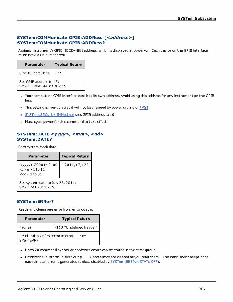
SYSTem Subsystem
SYSTem:COMMunicate:GPIB:ADDRess {<address>}SYSTem:COMMunicate:GPIB:ADDRess?
Assigns instrument's GPIB (IEEE-488) address, which is displayed at power-on. Each device on the GPIB interfacemust have a unique address.
Parameter Typical Return
0 to 30, default 10 +15
Set GPIB address to 15:SYST:COMM:GPIB:ADDR 15
l Your computer's GPIB interface card has its own address. Avoid using this address for any instrument on the GPIBbus.
l This setting is non-volatile; it will not be changed by power cycling or *RST.
l SYSTem:SECurity:IMMediate sets GPIB address to 10.
l Must cycle power for this command to take effect.
SYSTem:DATE <yyyy>, <mm>, <dd>SYSTem:DATE?
Sets system clock date.
Parameter Typical Return
<yyyy> 2000 to 2100<mm> 1 to 12<dd> 1 to 31
+2011,+7,+26
Set system date to July 26, 2011:SYST:DAT 2011,7,26
SYSTem:ERRor?
Reads and clears one error from error queue.
Parameter Typical Return
(none) -113,"Undefined header"
Read and clear first error in error queue:SYST:ERR?
l Up to 20 command syntax or hardware errors can be stored in the error queue.
l Error retrieval is first-in-first-out (FIFO), and errors are cleared as you read them. The instrument beeps onceeach time an error is generated (unless disabled by SYSTem:BEEPer:STATe OFF).
Agilent 33500 Series Operating and Service Guide 307
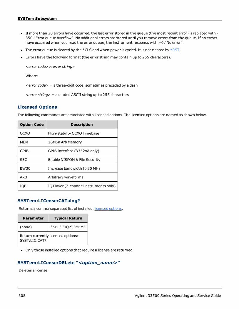
SYSTem Subsystem
l If more than 20 errors have occurred, the last error stored in the queue (the most recent error) is replacedwith -350,"Error queue overflow". No additional errors are stored until you remove errors from the queue. If no errorshave occurred when you read the error queue, the instrument responds with +0,"No error".
l The error queue is cleared by the *CLS andwhen power is cycled. It is not cleared by *RST.
l Errors have the following format (the error stringmay contain up to 255 characters).
<error code>,<error string>
Where:
<error code> = a three-digit code, sometimes preceded by a dash
<error string> = a quoted ASCII string up to 255 characters
Licensed Options
The following commands are associated with licensed options. The licensed options are named as shown below.
Option Code Description
OCXO High-stability OCXO Timebase
MEM 16MSa ArbMemory
GPIB GPIB Interface (3352xA only)
SEC Enable NISPOM & File Security
BW30 Increase bandwidth to 30 MHz
ARB Arbitrary waveforms
IQP IQ Player (2-channel instruments only)
SYSTem:LICense:CATalog?
Returns a comma separated list of installed, licensed options.
Parameter Typical Return
(none) "SEC","IQP","MEM"
Return currently licensed options:SYST:LIC:CAT?
l Only those installed options that require a license are returned.
SYSTem:LICense:DELete "<option_name>"
Deletes a license.
308 Agilent 33500 Series Operating and Service Guide

SYSTem Subsystem
Parameter Typical Return
{SEC|IQP|MEM|BW30} (none)
Delete license for IQ Player:SYST:LIC:DEL "IQP"
l Valid option names are double quoted strings representing the installed licensed options. They can be easily iden-tified using SYSTem:LICense:CATalog?.
SYSTem:LICense:DELete:ALL
Deletes all licenses.
Parameter Typical Return
(none) (none)
Delete all licenses:SYST:LIC:DEL:ALL
SYSTem:LICense:DESCription? "<option_name>"
Returns a description of specified option, regardless of whether it is currently licensed.
Parameter Typical Return
See list of licensed options "ExtendedMemory Option: 16 MSa/channel waveform memory"
Return description for option 002:SYST:LIC:DESC? "MEM"
l Option names are quoted strings representing options that may be licensed. Installed licensed items can be iden-tified with SYSTem:LICense:CATalog?.
SYSTem:LICense:ERRor?
Returns a string of all the errors produced by SYSTem:LICense:INSTall.
Parameter Typical Return
(none) #279File: MyFile.lic<CR><LF>[Ignored - The license file is not formatted cor-rectly.]<CR><LF>
Return the license installation error string:SYST:LIC:ERR?
l String can be up to 2096 characters.
l Returns a definite-length block containingmulti-line ASCII text, including carriage returns and line feeds.
Agilent 33500 Series Operating and Service Guide 309

SYSTem Subsystem
SYSTem:LICense:ERRor:COUNt?
Returns the number of license errors generated by SYSTem:LICense:INSTall.
Parameter Typical Return
(none) +0
Return number of license errors:SYST:LIC:ERR:COUN?
SYSTem:LICense:INSTall [{<folder> | <file>}]SYSTem:LICense:INSTall? <option>
This command installs all licenses from a specified file or from all license files in the specified folder. They query returns0 or 1 to indicate whether the specified license is installed.
Parameter Typical Return
<folder>may be anyvalid folder name. Defaultis root directory of a frontpanel USB storage device.
<file>may be any validlicense file name
<option is one of thelicensed options
0 (license not installed) or 1 (license installed)
Install licenses from a file:SYST:LIC:INSTALL "USB:\33522B_LICENSE071.lic"
l License files must have a ".lic" file extension.
l The format for <file> is "[<drive>:<path>]<file_name>", where <drive> can be INTernal or USB, and<path>must be an absolute folder path.
l INTernal specifies the internal flash file system.USB specifies a front panel USB storage device.e.
l If <drive>:<path> is omitted, the folder specified by the MMEMory:CDIRectory command is used.
l Absolute paths begin with "\" or "/" and start at the root folder of <drive>.
l Folder and file names cannot contain the following characters: \ / : * ? " < > |
l The combination of folder and file name cannot exceed 240 characters.
l The specified folder must exist and cannot be marked hidden or system.
SYSTem:LOCK:NAME?
Returns the current I/O interface (the I/O interface in use by the querying computer).
310 Agilent 33500 Series Operating and Service Guide

SYSTem Subsystem
Parameter Typical Return
(none) "LAN169.254.149.35"
See Interface Locking Examples
l After using this command to determine the name of the interface that you are using, use SYSTem:LOCK:OWNer?to determine which interface, if any, has the lock.
l Returns "USB", "VXI11", "GPIB", or "LAN <IP Address>" indicating the I/O interface being used by the queryingcomputer.
SYSTem:LOCK:OWNer?
Returns the I/O interface that currently has a lock.
Parameter Typical Return
(none) "LAN169.254.149.35"
See Interface Locking Examples
l When a lock is active, Bit 10 in the Standard Operation Register will be set (STATus:OPERation:CONDition?). Whenthe lock is released on all I/O interfaces, this bit will be cleared.
l Returns "USB", "VXI11", "GPIB", or "LAN <IP Address>" indicating the I/O interface that currently has a lock. Ifno interfaces have a lock, "NONE" is returned.
SYSTem:LOCK:RELease
Decrements the lock count by 1 andmay release the I/O interface from which the command is executed.
Parameter Typical Return
(none) (none)
See Interface Locking Examples
l When a lock is active, Bit 10 in the Standard Operation Register will be set (STATus:OPERation:CONDition?). Whenthe lock is released on all I/O interfaces, this bit will be cleared.
SYSTem:LOCK:REQuest?
Requests a lock of the current I/O interface. This allows you to lock the instrument's configuration or cooperativelyshare the instrument with other computers.
Parameter Typical Return
(none) 0 (denied) or 1 (granted)
See Interface Locking Examples
Agilent 33500 Series Operating and Service Guide 311

SYSTem Subsystem
l Lock requests can be nested; each request increases lock count by 1. For every request, you will need a release ( SYSTem:LOCK:RELease) from the same I/O interface.
l Locks are handled at the I/O interface level (USB, LAN, etc.) and you are responsible for all coordination betweenthreads and/or programs on that interface.
l When a request is granted, only I/O sessions from the present interface will be allowed to change the state of theinstrument. You can only query the instrument state from other I/O interfaces.
l LAN sessions locks are automatically releasedwhen a LAN disconnect is detected.
l Granting a lock sets Bit 10 in the Standard Operation Register (STATus:OPERation:CONDition?).
SYSTem:SECurity:IMMediate
Sanitizes all user-accessible instrument memory. This command complies with requirements in chapter 8 of theNational Instrument Security Program OperatingManual (NISPOM).
Parameter Typical Return
(none) (none)
Sanitize all user-accessible instrument memory:SYST:SEC:IMM
This command is recommended for customers, such as military contractors, whomustcomply with NISPOM. Excessive use of this commandmay cause premature failure ofthe flash memory.
This command destroys all user-defined state information, user-defined arbitrary wave-forms, and user-defined I/O settings such as the IP address.
l Typically used before removing an instrument from a secure area.
l Initializes all instrument settings to their Factory Reset (*RST) values.
SYSTem:TIME <hh>, <mm>, <ss>SYSTem:TIME?
Sets system clock time.
Parameter Typical Return
<hh> 0 to 23<mm> 0 to 59<ss> 0 to 60
20,15,30.000
Set system Time to 20:15:30 (8:15:30 PM)SYST:TIM 20,15,30
l This time is used for file timestamps in the Mass Memory (MMEMory) system.
312 Agilent 33500 Series Operating and Service Guide

SYSTem Subsystem
SYSTem:VERSion?
Returns version of the SCPI (Standard Commands for Programmable Instruments) that the instrument complies with.Cannot be determined from front panel.
Parameter Typical Return
(none) 1994.0
Return the SCPI version:SYST:VERS?
Interface Locking Examples
The following series of commands illustrates usage.
Initial State = unlocked, Count = 0
<FROM USB> SYST:LOCK:REQ? returns 1 (request successful)
State = locked, Count = 1
<FROM LAN> SYST:LOCK:REQ? returns 0 because USB has lock
State = locked, Count = 1
<FROM USB> SYST:LOCK:REQ? returns 1 (request successful)
State = locked, Count = 2
<FROM USB> SYST:LOCK:REL
State = locked, Count = 1
<FROM USB> SYST:LOCK:REL
State = unlocked, Count = 0
Note that for each successful lock request, a lock release is required. Two requests require two releases.
Agilent 33500 Series Operating and Service Guide 313

LAN Configuration
LAN ConfigurationConfigures instrument for remote operation via the local area network (LAN).
The instrument uses LAN port 5024 for SCPI Telnet sessions, and port 5025 for SCPISocket sessions.
Dot Notation Details
Dot-notation addresses ("nnn.nnn.nnn.nnn" where "nnn" is a byte value from 0 to 255)must be expressedwith care,as most PC web software interprets byte values with leading zeros as octal (base 8) numbers. For example,"192.168.020.011" is actually equivalent to decimal "192.168.16.9" because ".020" is interpreted as "16" expressedin octal, and ".011" as "9". To avoid confusion, use only decimal values from 0 to 255, with no leading zeros.
SYSTem:COMMunicate:LAN:CONTrol?
Reads the initial Control connection port number for Sockets communications. This connection is used to send andreceive commands and queries.
Parameter Typical Return
(none) 5000 (0 if the interface does not support sockets)
Return the Control connection port number:SYST:COMM:LAN:CONT?
l Use the Control socket connection to send a Device Clear to the instrument or to detect pending Service Request(SRQ) events. The Device Clear command is "DCL".
SYSTem:COMMunicate:LAN:DHCP {ON|1|OFF|0}SYSTem:COMMunicate:LAN:DHCP?
Disables or enables instrument's use of DHCP. The acronym DHCP stands for Dynamic Host Configuration Protocol, aprotocol for assigning dynamic IP addresses to networked devices. With dynamic addressing, a device can have a dif-ferent IP address every time it connects to the network.
ON: instrument tries to obtain an IP address from a DHCP server. If a DHCP server is found, it assigns a dynamic IPaddress, Subnet Mask, and Default Gateway to the instrument.
OFF or DHCP unavailable: instrument uses the static IP address, Subnet Mask, and Default Gateway during power-on.
If you change this setting, you must send SYSTem:COMMunicate:LAN:UPDate to activate the newsetting.
Parameter Typical Return
{ON|1|OFF|0}, default ON 0 (OFF) or 1 (ON)
Disable DHCP:SYST:COMM:LAN:DHCP OFFSYST:COMM:LAN:UPDate
314 Agilent 33500 Series Operating and Service Guide

LAN Configuration
l Most corporate LANs have a DHCP server.
l If DHCP LAN address not assigned by DHCP server, static IP is assumed after approximately twominutes.
l This setting is non-volatile; it will not be changed by power cycling or *RST.
l Enabled when the instrument is shipped from the factory or after SYSTem:SECurity:IMMediate.
SYSTem:COMMunicate:LAN:DNS[1|2] "<address>"SYSTem:COMMunicate:LAN:DNS[1|2]? [{CURRent|STATic}]
Assigns static IP addresses of Domain Name System (DNS) servers. A primary and a secondary server address may beassigned. Contact your LAN administrator for details. If DHCP is available and enabled, DHCP will auto-assign the DNSserver addresses. These auto-assigned DNS server addresses take precedence over the static DNS addresses assignedwith this command.
If you change this setting, you must send SYSTem:COMMunicate:LAN:UPDate to acti-vate the new setting.
Parameter Typical Return
Command: "nnn.nnn.nnn.nnn", default "0.0.0.0"
Query: {CURRent|STATic}, default CURRent
"198.105.232.4"
Set a static primary DNS address:SYST:COMM:LAN:DNS "198.105.232.4"SYST:COMM:LAN:UPD
l CURRent: read address currently being used by the instrument.
l STATic: read static address from non-volatile memory. This address is used if DHCP is disabled or unavailable.
l This setting is non-volatile; it will not be changed by power cycling or *RST.
l Set to "0.0.0.0" by SYSTem:SECurity:IMMediate.
SYSTem:COMMunicate:LAN:DOMain?
Returns the domain name of the LAN to which the instrument is connected.
Parameter Typical Return
(none) "example.com"
Return domain name being used by instrument:SYST:COMM:LAN:DOM?
l If Dynamic domain name System (DNS) is available on your network and your instrument uses DHCP, the domainname is registered with the Dynamic DNS service at power-on.
l A null string ("") indicates that no domain name is assigned.
Agilent 33500 Series Operating and Service Guide 315

LAN Configuration
SYSTem:COMMunicate:LAN:GATeway "<address>"SYSTem:COMMunicate:LAN:GATeway? [{CURRent|STATic}]
Assigns a default gateway for the instrument. The specified IP Address sets the default gateway which allows theinstrument to communicate with systems that are not on the local subnet. Thus, this is the default gateway wherepackets are sent which are destined for a device not on the local subnet, as determined by the Subnet Mask setting. IfDHCP is enabled (SYSTem:COMMunicate:LAN:DHCP ), the specified default gateway is not used. However, if the DHCPserver fails to assign a valid IP address, the currently configured default gateway will be used. Contact your LAN admin-istrator for details.
If you change this setting, you must send SYSTem:COMMunicate:LAN:UPDate to activate the newsetting.
Parameter Typical Return
Command: "nnn.nnn.nnn.nnn", default "0.0.0.0"
Query: {CURRent|STATic}, default CURRent
"198.105.232.1"
Set default gateway address:SYST:COMM:LAN:GATEWAY "198.105.232.1"SYST:COMM:LAN:UPD
l CURRent: read address currently being used by the instrument.
l STATic: read static address from non-volatile memory. This address is used if DHCP is disabled or unavailable.
l Set to "0.0.0.0" when instrument is shipped from factory or after SYSTem:SECurity:IMMediate.
SYSTem:COMMunicate:LAN:HOSTname "<name>"SYSTem:COMMunicate:LAN:HOSTname? [{CURRent | STATic}]
Assigns a hostname to the instrument. A hostname is the host portion of the domain name, which is translated intoan IP address. If Dynamic Domain Name System (DNS) is available on your network and your instrument uses DHCP,the hostname is registered with the Dynamic DNS service at power-on. If DHCP is enabled (SYS-Tem:COMMunicate:LAN:DHCP ), the DHCP server can change the specified hostname.
If you change this setting, you must send SYSTem:COMMunicate:LAN:UPDate toactivate the new setting.
Parameter Typical Return
String of up to 15 characters.Must start with letter (A-Z)May contain letters, numbers (0-9), or dashes ("-")
"LAB1-33522A"
Define a hostname:SYST:COMM:LAN:HOST "LAB1"SYST:COMM:LAN:UPD
316 Agilent 33500 Series Operating and Service Guide

LAN Configuration
l Set to "A-33521A-nnnnn" or "A-33522A-nnnnn", where nnnnn is the last five digits of the instrument's serialnumber, when the instrument is shipped from the factory or after SYSTem:SECurity:IMMediate.
l If no hostname exists, a null string ( "" ) is returned.
SYSTem:COMMunicate:LAN:IPADdress "<address>"SYSTem:COMMunicate:LAN:IPADdress? [{CURRent|STATic}]
Assigns a static Internet Protocol (IP) address for the instrument. If DHCP is enabled (SYS-Tem:COMMunicate:LAN:DHCP), the specified static IP address is not used. Contact your LAN administrator for details.
If you change this setting, you must send SYSTem:COMMunicate:LAN:UPDate toactivate the new setting.
Parameter Typical Return
Command: "nnn.nnn.nnn.nnn", default "0.0.0.0"
Query: {CURRent|STATic}, default CURRent
"169.254.149.35"
Set a static IP address:SYST:COMM:LAN:IPAD "169.254.149.35"SYST:COMM:LAN:UPD
l CURRent: read address currently being used by the instrument.
l STATic: read static address from non-volatile memory. This address is used if DHCP is disabled or unavailable.
l This setting is non-volatile; it will not be changed by power cycling or *RST.
l Set to "169.254.5.21" when the instrument is shipped from the factory or after SYSTem:SECurity:IMMediate.
SYSTem:COMMunicate:LAN:MAC?
Reads the instrument's Media Access Control (MAC) address.
Your LAN administrator may need the MAC address to assign a static IP address for this device.
Parameter Typical Return
(none) "0030D3001041"
Return the MAC address:SYST:COMM:LAN:MAC?
l The MAC address is also known as the link-layer address, the Ethernet (station) address, LANIC ID, or HardwareAddress. This is an unchangeable 48-bit address assigned by the manufacturer to each unique Internet device.
l The instrument's MAC address is set at the factory and cannot be changed.
l This setting is non-volatile; it will not be changed by power cycling or *RST.
Agilent 33500 Series Operating and Service Guide 317

LAN Configuration
SYSTem:COMMunicate:LAN:SMASk "<mask>"SYSTem:COMMunicate:LAN:SMASk? [{CURRent | STATic}]
Assigns a subnet mask for the instrument. The instrument uses the subnet mask to determine whether a client IPaddress is on the same local subnet. When a client IP address is on a different subnet, all packets must be sent to theDefault Gateway. Contact your LAN administrator for details.
If you change this setting, you must send SYSTem:COMMunicate:LAN:UPDate to activate the newsetting.
Parameter Typical Return
Command: "nnn.nnn.nnn.nnn", default "0.0.0.0"
Query: {CURRent|STATic}, default CURRent
"255.255.0.0"
Set the subnet mask:SYST:COMM:LAN:SMAS "255.255.255.0"SYST:COMM:LAN:UPD
l If DHCP is enabled (SYSTem:COMMunicate:LAN:DHCP ), the specified subnet mask is not used. However, if theDHCP server fails to assign a valid IP address, the instrument uses the AutoIP subnet mask.
l A value of "0.0.0.0" or "255.255.255.255" indicates that subnetting is not being used.
l This setting is non-volatile; it will not be changed by power cycling or *RST.
l The subnet mask is set to "255.255.0.0" when the instrument is shipped from the factory or after a SYS-Tem:SECurity:IMMediate command.
l CURRent: read address currently being used by the instrument.
l STATic: read static address from non-volatile memory. This address is used if DHCP is disabled or unavailable.
SYSTem:COMMunicate:LAN:TELNet:PROMpt "<string>"SYSTem:COMMunicate:LAN:TELNet:PROMpt?
Sets the command prompt seen when communicating with the instrument via Telnet.
Parameter Typical Return
String of up to 15 characters "Command>"
Set the command prompt:SYST:COMM:LAN:TELN:PROM "Command>"
l A Telnet session is typically started from a host computer shell:
telnet <IP_address> <port>
For example: telnet 169.254.4.10 5024
To exit a Telnet session, press <Ctrl-D>.
318 Agilent 33500 Series Operating and Service Guide

LAN Configuration
l This setting is non-volatile; it will not be changed by power cycling or *RST.
l This is set to "33521A> " (Agilent 33521A), "33522A> " (Agilent 33522A), or "33500> " (other 33500 Seriesinstruments) when the instrument is shipped from the factory or after SYSTem:SECurity:IMMediate.
SYSTem:COMMunicate:LAN:TELNet:WMESsage "<string>"SYSTem:COMMunicate:LAN:TELNet:WMESsage?
Sets welcomemessage seen when communicating with instrument via Telnet.
Parameter Typical Return
String of up to 63 characters "Welcome to the Telnet Session"
Define a welcomemessage:SYST:COMM:LAN:TELN:WMES "Welcome to the Telnet Session"
l This setting is non-volatile; it will not be changed by power cycling or *RST.
l This is set to "Welcome to Agilent's 33521AWaveform Generator" (Agilent 33521A), "Welcome to Agilent's33522AWaveform Generator" (Agilent 33522A), or "Welcome to Agilent's 33500-Series Waveform Generator"(other 33500 Series instruments) when the instrument is shipped from the factory or after SYS-Tem:SECurity:IMMediate.
SYSTem:COMMunicate:LAN:UPDate
Stores any changesmade to the LAN settings into non-volatile memory and restarts the LAN driver with the updatedsettings.
Parameter Typical Return
(none) (none)
(see below)
l This commandmust be sent after changing the settings for DHCP, DNS, gateway, hostname, IP address, subnetmask, WINS.
l Make all changes to the LAN settings before sending this command.
Example
The following example configures the instrument to use statically assigned LAN settings.
SYST:COMM:LAN:DHCP OFF
SYST:COMM:LAN:DNS "198.105.232.4"
SYST:COMM:LAN:DNS2 "198.105.232.5"
SYST:COMM:LAN:GATEWAY "198.105.232.1"
SYST:COMM:LAN:HOST "LAB1-33522A"
SYST:COMM:LAN:IPAD "198.105.232.101"
SYST:COMM:LAN:SMAS "255.255.255.0"
SYST:COMM:LAN:WINS "198.105.232.4"
Agilent 33500 Series Operating and Service Guide 319

LAN Configuration
SYST:COMM:LAN:WINS "198.105.232.5"
SYST:COMM:LAN:UPD
The following example configures the instrument back to use DHCP.
SYST:COMM:LAN:DHCP ON
SYST:COMM:LAN:UPD
SYSTem:COMMunicate:LAN:WINS[1|2] "<address>"SYSTem:COMMunicate:LAN:WINS[1|2]? [{CURRent | STATic}]
Assigns the static IP addresses of the Windows Internet Name System (WINS) servers. A primary and a secondaryserver address may be assigneContact your LAN administrator for details.tails. If DHCP is available and enabled, DHCPwill auto-assign the WINS server addresses. These auto-assignedWINS server addresses take precedence over thestatic WINS addresses assignedwith this command.
If you change this setting, you must send SYSTem:COMMunicate:LAN:UPDate to acti-vate the new setting.
Parameter Typical Return
Command: "nnn.nnn.nnn.nnn", default "0.0.0.0"
Query: {CURRent|STATic}, default CURRent
"198.105.232.4"
Set a static primary WINS address:SYST:COMM:LAN:WINS "198.105.232.4"SYST:COMM:LAN:UPD
l The assignedWINS addresses are used if DHCP is disabled or unavailable. Otherwise, the WINS server addressesare auto-assigned by DHCP.
l This setting is non-volatile; it will not be changed by power cycling or *RST.
l Set to "0.0.0.0" (no servers) after SYSTem:SECurity:IMMediate.
l CURRent: read address currently being used by the instrument.
l STATic: read static address from non-volatile memory. This address is used if DHCP is disabled or unavailable.
320 Agilent 33500 Series Operating and Service Guide

[SOURce[1|2]:]TRACk {ON|OFF|INVerted}
[SOURce[1|2]:]TRACk {ON|OFF|INVerted}Causes channels 1 and 2 of a two-channel instrument to output the same signal, or an inverted polarity signal.
Parameter Typical Return
{ON|OFF|INVerted} ON, OFF, or INV
Set channel 2 to output a signal identical to that of channel 1:TRACk ON
l Causes all settings of the named channel to be copied to the other channel with exceptions noted below. This doesinclude frequency list settings and any arbitrary waveforms loaded in memory.
l With the INVerted option, the tracking channel's amplitude will be inverted, forming a signal similar to a dif-ferential output between Channel 1 and Channel 2. DC Offset is not inverted.
l When TRACk is ON, voltage limits on both channels apply. If voltage limits on either channel would prevent theother channel's setup from being applied, the instrument will generate a settings conflict error and channel track-ing will remain OFF.
l When TRACk is ON, changes to either channel are reflected in both channels. When TRACk is changed from ON orINV to OFF, the channels will remain in their present setup (frequency, amplitude, and so on), but you may nowchange one channel without affecting the other channel.
l Voltage limits may be adjusted in trackingmode, but cannot be set in violation of the current signal.
l Turning tracking ON sets COMBine:FEED to NONE, turns off FREQuency:COUPle, VOLTage:COUPle, and RATE:CO-UPle.
l TRACK is not allowed if the internal modulation source for the channel being tracked is the other channel.
l The OUTPut:SYNC:SOURce is set to the channel being tracked.
Agilent 33500 Series Operating and Service Guide 321

TRIGger Subsystem Introduction
TRIGger Subsystem IntroductionConfigures triggering for sequence, list, burst, and sweep:
TRIGger[1|2] - immediate trigger
TRIGger[1|2]:COUNt - trigger count
TRIGger[1|2]:DELay - trigger delay
TRIGger[1|2]:SLOPe - slope of trigger signal at the rear-panel Ext Trig connector
TRIGger[1|2]:SOURce - source (internal, external, timer, or bus) from which instrument accepts trigger
TRIGger[1|2]:TIMer? - timer usedwhen TRIGger[1|2]:SOURce is TIMer.
TRIGger[1|2]
Forces immediate trigger to initiate sequence, sweep, list, or burst.
Parameter Typical Return
(none) (none)
Send an immediate trigger on channel 2:TRIG
l Can be usedwith IMMediate, EXTernal, or BUS trigger source (TRIGger[1|2]:SOURce). For example, you can useTRIGger to issue an immediate trigger while waiting for an external trigger.
l Intended as an override. For general, software controlled triggering, use *TRG.
TRIGger[1|2]:COUNt <number>TRIGger[1|2]:COUNt?
Sets trigger count.
Parameter Typical Return
1 to 1,000,000; default, 1 10000
Set channel 2 trigger count to 10000:TRIG2:COUN 10000
l Can be usedwith IMMediate, EXTernal, or BUS trigger source (TRIGger[1|2]:SOURce).
l Applies only when INITiate[1|2]:CONTinuous is OFF.
TRIGger[1|2]:DELay <seconds|MINimum|MAXimum>TRIGger[1|2]:DELay?
Sets trigger delay, (time from assertion of trigger to occurrence of triggered event).
322 Agilent 33500 Series Operating and Service Guide

TRIGger Subsystem Introduction
Parameter Typical Return
0 to 1000 s, in resolution of 4 ns; default 0 +1.050000000000000E-01
Set channel 1 trigger delay to 105 ms:TRIG:DEL 105e-3
l Can be usedwith IMMediate, EXTernal, or BUS trigger source (TRIGger[1|2]:SOURce).
TRIGger[1|2]:SLOPe {POSitive|NEGative}TRIGger[1|2]:SLOPe?
Specifies polarity of trigger signal on rear-panel Trig In connector for any externally-triggeredmode.
Parameter Typical Return
{POSitive|NEGative}, default POS (rising edge) POS or NEG
Set trigger slope to falling edge:TRIG:SLOP NEG
TRIGger[1|2]:SOURce {IMMediate|EXTernal|TIMer|BUS}TRIGger[1|2]:SOURce?
Selects the trigger source for sequence, list, burst or sweep. The instrument accepts an immediate or timed internaltrigger, an external hardware trigger from the rear-panel Ext Trig connector, or a software (bus) trigger.
Parameter Typical Return
{IMMediate|EXTernal|TIMer|BUS}, default IMMediate IMM, EXT, TIM, BUS
Select external trigger source (trigger each time a low-true TTL pulse is received on the rear-panel trigger input):TRIG:SOUR EXT
In triggered burst mode:
l The instrument outputs a waveform of the specified number of cycles (burst count) when a trigger received. Afterthe specified number of cycles have been output, the instrument stops andwaits for next trigger.
l IMMediate (internal): the instrument outputs continuously when burst mode is enabled. The rate at which theburst is generated is determined by BURSt:INTernal:PERiod.
l EXTernal: the instrument accepts a hardware trigger at the rear-panel Ext Trig connector. The instrument out-puts one burst of the specified number of cycles each time Ext Trig receives a TTL pulse with the proper polarity(TRIGger[1|2]:SLOPe). External trigger signals during a burst are ignored.
l BUS (software): the instrument initiates one burst each time a bus trigger (*TRG) is received. The front-panel[Trigger] key is illuminated when the instrument is waiting for a bus trigger.
l EXTernal or BUS: burst count and burst phase remain in effect, but burst period is ignored.
l TIMer: trigger events are spaced by a timer, with the first trigger as soon as INIT occurs.
In frequency sweepmode:
Agilent 33500 Series Operating and Service Guide 323

TRIGger Subsystem Introduction
l IMMediate (internal): the instrument outputs continuously when the sweep is enabled. The period at whichthe sweep is generated is the sweep time (SWEep:TIME) plus 1 ms.
l EXTERNAL: the instrument accepts a hardware trigger at the rear-panel Ext Trig connector. The instrument ini-tiates one sweep each time Trig In receives a TTL pulse of proper edge polarity (TRIGger[1|2]:SLOPe). The triggerperiodmust be at least sweep time (SWEep:TIME) plus 1 ms.
l BUS (software): the instrument initiates one sweep each time a bus trigger (*TRG) is received. The front-panel[Trigger] key is illuminated when the instrument is waiting for a bus trigger.
l APPLy sets trigger source to IMMediate.
l To ensure synchronization with BUS source, send *WAI (wait) so the instrument waits for all pending operationsto complete before executing any additional commands. For example, the following command string guaranteesthat the first trigger is accepted and the operation is executed before second trigger is recognized.
TRIG:SOUR BUS;*TRG;*WAI;*TRG;*WAI
l Use *OPC? or *OPC to determine when the sweep or burst is complete. The *OPC? query returns 1 to the outputbuffer when the sweep or burst is complete. The *OPC command sets the Operation Complete bit (bit 0) in theStandard Event register when the sweep or burst is complete.
TRIGger[1|2]:TIMer {<seconds>|MINimum|MAXimum} TRIGger[1|2]:TIMer? {MINi-mum|MAXimum}
Sets timer usedwhen TRIGger[1|2]:SOURce is TIMer.
Parameter Typical Return
1 µs to 8,000 s +3.000000000000000E-01
Set trigger timer to 300 ms on channel 2:TRIG2:TIM 0.3
l In triggered burst mode (BURSt:MODE TRIG), this command supersedes BURSt:INTernal:PERiod.
324 Agilent 33500 Series Operating and Service Guide

UNIT:ANGLe {DEGree|RADian|DEFault}UNIT:ANGLe?
UNIT:ANGLe {DEGree|RADian|DEFault}UNIT:ANGLe?Selects degrees or radians as the angle units. The selected units are used for setting the starting phase for a burst(BURSt:PHASe), or for setting the phase offset (PHASe). The associated queries are also affected.
Parameter Typical Return
{DEGree|RADian|DEFault}, default DEGree DEG or RAD
Set angle units to radians:UNIT:ANGL RAD
l Settingmay be overridden by adding units to numeric parameter in command. For example, PHASE 90 DEG spec-ifies 90 degrees, regardless of this setting.
l Front panel display always shows degrees, regardless of UNIT:ANGLe setting.
Agilent 33500 Series Operating and Service Guide 325

VOLTage Subsystem Introduction
VOLTage Subsystem IntroductionThe VOLTage subsystem sets parameters related to output voltage.
Example
The following is a typical procedure using the VOLTage subsystem.
1. Select the waveform shape, amplitude and offset: Use APPLy or the equivalent FUNCtion, FREQuency,VOLTage, and VOLTage:OFFSet commands to select the function, frequency, amplitude, and offset.
2. Set units for output amplitude:VOLTage:UNIT
3. Set output amplitude:VOLTage
4. Set DC offset voltage:VOLTage:OFFSet
5. Set high and low voltage level:VOLTage:HIGH and VOLTage:LOW
6. Select output voltage limits to protect device under test (DUT):VOLTage:LIMit:HIGH, VOLT-age:LIMit:LOW, and VOLTage:LIMit:STATe
7. Select status of auto-ranging for all output functions:VOLTage:RANGe:AUTO
8. Set voltage coupling to lock amplitude and offset of the channels together (2-channel instrumentsonly):VOLTageLCOUPle[:STATe]
This example demonstrates the procedure outlined above:
SOURce1:FUNCtion SQU
SOURce1:FREQuency +1.0E+06
SOURce1:VOLTage +0.5
SOURce1:VOLTage:OFFSet +0.5
SOURce1:FUNCtion:SQUare:PERiod +1.0E-06
SOURce1:FUNCtion:PULSe:PERiod +1.0E-06
SOURce1:VOLTage:LIMit:LOW +0.0
SOURce1:VOLTage:LIMit:HIGH +1.0
SOURce1:VOLTage:LIMit:STATe 1
OUTP1 ON
SOURce2:FUNCtion SIN
SOURce2:FREQuency +1.0E+06
SOURce2:VOLTage +2.0
SOURce2:VOLTage:OFFSet +0.0
SOURce2:VOLTage:LIMit:LOW -1.0
SOURce2:VOLTage:LIMit:HIGH +1.0
SOURce2:VOLTage:LIMit:STATe 1
OUTP2 ON
[SOURce[1|2]:]VOLTage {<amplitude>|MINimum|MAXimum}[SOURce[1|2]:]VOLTage? [{MINimum|MAXimum}]
Sets output amplitude.
326 Agilent 33500 Series Operating and Service Guide

VOLTage Subsystem Introduction
Parameter Typical Return
1 mVpp to 10 Vpp into 50 Ω, default 100 mVpp +5.0000000000000E+00
Set output amplitude to 5 Vpp:VOLT 5 Vpp
l The relationship between offset voltage and output amplitude is shown below. Vmax is the maximum peak voltagefor the selected output termination (5 V for a 50 Ω load or 10 V for a high-impedance load).
|Voffset| < Vmax - Vpp/2
If the specified offset voltage is not valid, the instrument will adjust it to the maximum DC voltage allowedwith thespecified amplitude. From the remote interface, a "Data out of range" error will also be generated.
l Differences between remote and front panel operation:
l Remote Interface: Setting amplitude from the remote interface can change the offset in order to achieve thedesired amplitude. The instrument will generate either a "Data out of range" or "Settings conflict" error. If thespecified offset voltage is not valid, the instrument adjusts it to the maximum allowedwith the specified ampli-tude.
l Front Panel: Setting amplitude from the front panel will not change the offset setting. If the specified ampli-tude is not valid, the instrument clips it to the maximum amplitude allowedwith the current offset and gen-erates a "Data out of range" error.
l Limits Due to Output Termination: If the amplitude is 10 Vpp and you change the output termination setting from50 Ω to "high impedance" (OUTPut[1|2]:LOAD INF), the displayed amplitude doubles to 20 Vpp. Changing from"high impedance" to 50 Ω halves the displayed amplitude. The output termination setting does not affect theactual output voltage; it only changes the values displayed and queried from the remote interface. Actual outputvoltage depends on the connected load.
l Limits due to Output Coupling:
l Differences between remote and front panel operation: If two channels are coupled, both channels' amplitudelimitations will be checked before a change in amplitude is executed. If a change in output amplitude wouldexceed a LIMIT for either channel, or exceed the instrument's output specifications for either channel:
l Remote interface: The instrument will first adjust the offset, then if necessary, the amplitude of thatchannel to comply with the voltage limits or specification. The instrument will generate either a "Data outof range" or "Settings conflict" error.
l Front panel: The instrument will clip the amplitude value to the maximum value with the current offsetsetting. A "Data out of range" error will be generated.
l Specifying Voltage Units: You can set the output amplitude in Vpp, Vrms, or dBm by specifying the units as part ofthe VOLTage command VOLT 3.0 VRMS.
Use VOLTage:UNIT to specify output units for all subsequent commands.
You cannot specify output amplitude in dBm if output termination is set to high impedance.The units are auto-matically converted to Vpp.
l Limits Due to Units Selection:Amplitude limits are sometimes determined by the output units selected. This mayoccur when the units are Vrms or dBm due to the differences in various functions' crest factors. For example, if youchange a 5 Vrms square wave (into 50 Ω) to a sine wave, the instrument will adjust the amplitude to 3.536 Vrms(the upper limit for sine in Vrms). The remote interface will also generate a "Settings conflict" error.
Agilent 33500 Series Operating and Service Guide 327

VOLTage Subsystem Introduction
l Arbitrary Waveform Limitations: For arbitrary waveforms, amplitude is limited if the waveform data points do notspan the full range of the output DAC (Digital-to-Analog Converter). For example, the built-in "Sinc" waveformdoes not use the full range of values, so its maximum amplitude is limited to 6.087 Vpp (into 50 Ω).
l Changing amplitude may briefly disrupt output at certain voltages due to output attenuator switching. The ampli-tude is controlled, however, so the output voltage will never exceed the current setting while switching ranges. Toprevent this disruption, disable voltage autoranging using VOLTage:RANGe:AUTOOFF. The APPLy command auto-matically enables autoranging.
l You can also set the amplitude (with an associated offset voltage) by specifying a high level (VOLTage:HIGH) andlow level (VOLTage:LOW). For example, if you set the high level to +2 V and the low level to -3 V, the resultingamplitude is 5 Vpp, with a -500 mV offset.
l To output a DC voltage level, select the DC voltage function (FUNCtion DC) and then set the offset voltage (VOLT-age:OFFSet). Valid values are between ±5 VDC into 50 Ω or ±10 VDC into an open circuit. While the instrument isin DCmode, setting amplitude has no effect.
[SOURce[1|2]:]VOLTage:COUPle[:STATe] {ON|1|OFF|0}[SOURce[1|2]:]VOLTage:COUPle[:STATe]?
Enables or disables the maintaining of the same amplitude, offset, range, load, and units on both channels of a two-channel instrument. The command applies to both channels; the SOURce keyword is ignored.
Parameter Typical Return
{ON|1|OFF|0}, default OFF 0 (OFF) or 1 (ON)
Enable voltage coupling:VOLT:COUP ON
[SOURce[1|2]:]VOLTage:HIGH {<voltage>|MINimum|MAXimum}[SOURce[1|2]:]VOLTage:HIGH? [{MINimum|MAXimum}]
[SOURce[1|2]:]VOLTage:LOW {<voltage>|MINimum|MAXimum}[SOURce[1|2]:]VOLTage:LOW? [{MINimum|MAXimum}]
Set the waveform's high and low voltage levels.
Parameter Typical Return
±5 VDC into 50 Ω, as long as HIGH is at least 1 mV greater than LOW. Defaults:HIGH +50 mV, LOW -50 mV.
+4.000000000000000E+00
Set high voltage level to 4 V:VOLT:HIGH 4
l Limits Due to Amplitude: You can set the voltage levels to a positive or negative value with the restrictions shownbelow. Vpp is the maximum peak-to-peak amplitude for the selected output termination (10 Vpp into 50 Ω or 20Vpp into an open circuit).
Vhigh
– Vlow
≤ Vpp (max) and Vhigh
, Vlow
≤ Vpp (max)/2
328 Agilent 33500 Series Operating and Service Guide

VOLTage Subsystem Introduction
l Differences between remote and front panel operation:
l Remote Interface: Setting the high or low level from the remote interface can change the high level or lowlevel to achieve the desired setting. In this case either a "Data out of range" or "Settings conflict" error willoccur. If the high level is set below the low level, the instrument will set the low level 1 mV less than the highlevel. If the high level is set below the LOW limit or the instrument output specifications, the low level will beset to the LOW limit or instrument output specification and the high level will be set 1 mV above the low level.A similar set of rules applies if the low level is set incorrectly.
l Front Panel: Setting the high or low level from the front panel may clip that level setting in order to achievethe desired level setting, and a "Data out of range" error will be generated. The high level cannot be set belowthe low level from the front panel.
l Setting the high and low levels also sets the waveform amplitude and offset. For example, if you set the high levelto +2 V and the low level to -3 V, the resulting amplitude is 5 Vpp, with a -500 mV offset.
l Limits Due to Output Termination:If the amplitude is 10 Vpp and you change the output termination setting from50 Ω to "high impedance" (OUTPut[1|2]:LOAD INF), the displayed amplitude doubles to 20 Vpp. Changing from"high impedance" to 50 Ω halves the displayed amplitude. The output termination setting does not affect theactual output voltage; it only changes the values displayed and queried from the remote interface. Actual outputvoltage depends on the connected load.
l Limits due to VOLTage:LIMit:STATe: If voltage limits are enabled, the level settings are checked against the spec-ified limits (VOLTage:LIMit:HIGH, VOLTage:LIMit:LOW) before a level change is executed. If an output levelchange would exceed a LIMIT setting, the level is clipped to the maximum (or minimum) value allowed that willnot exceed the LIMit setting and a "Settings conflict" error will be generated.
l Limits due to Output Coupling: If two channels are coupled, limitations are checked on both channels before achange in level is executed. If a change in level would exceed a LIMIT setting or exceed the instrument's outputspecifications for either channel, the level is clipped to the maximum (or minimum) value allowed that will notexceed the LIMit setting and a "Settings conflict" error will be generated.
l To invert the waveform relative to the offset voltage, use OUTPut[1|2]:POLarity.
[SOURce[1|2]:]VOLTage:LIMit:HIGH {<voltage>| MAXimum|MINimum}[SOURce[1|2]:]VOLTage:LIMit:HIGH? {MAXimum|MINimum}
[SOURce[1|2]:]VOLTage:LIMit:LOW {<voltage>|MAXimum|MINimum}[SOURce[1|2]:]VOLTage:LIMit:LOW? {MAXimum|MINimum}?
Sets the high and low limits for output voltage.
Parameter Typical Return
±5 VDC into 50 Ω, as long as HIGH is at least 1 mV greater than LOW. Defaults:HIGH +50 mV, LOW -50 mV.
+5.0000000000000E+00
Set channel 1 output high limit to 5 V:VOLT:LIMIT:HIGH 5.0VOLT:LIMIT:STATE ON
l For voltage limits to be in effect, VOLTage:LIMit:STATe must be ON. If this is the case, and the high limit is setbelow the high value of the signal or the low limit is set above the low value of the signal, the relevant limit will beclipped to the high or low value of the signal. The instrument will generate either a "Data out of range" or "Settings
Agilent 33500 Series Operating and Service Guide 329

VOLTage Subsystem Introduction
conflict" error.
l The high limit sets the highest output voltage allowed to be set, including DCOffset and peak amplitude. It is set inreference to the current OUTPUT[1|2]:LOAD setting. If the specified LOAD impedance is not present at the instru-ment's output, then the output limit may not represent the actual voltages at the output connector. For example,if the output impedance is set to 50 Ω, but the actual load is high impedance, then the actual output peak voltagemay be up to twice the specified limit voltage.
l Specifying Voltage Units: You can set the output limit voltage only in volts.
l When VOLTage:COUPle[:STATe] is ON, and VOLTage:LIMit:STATe is ON, voltage limit settings on both channelsaffect maximum amplitude and offset voltage settings on both channels. The most restrictive combination of highand low limits from either channel is used.
[SOURce[1|2]:]VOLTage:LIMit:STATe {ON|1|OFF|0}[SOURce[1|2]:]VOLTage:LIMit:STATe?
Enables or disables output amplitude voltage limits.
Parameter Typical Return
{ON|1|OFF|0}, default OFF 0 (OFF) or 1 (ON)
Set and enable ±2.5 V output limits on channel 1:VOLT:LIM:HIGH 2.5VOLT:LIM:LOW -2.5VOLT:LIM:STAT ON
l When this is turned ON, if the present settings of amplitude and offset exceed the limits, then the limits will be dis-abled. The instrument will generate either a "Settings conflict" error.
l When VOLTage:COUPle[:STATe] is ON, and VOLTage:LIMit:STATe is ON, voltage limit settings on both channelsaffect maximum amplitude and offset voltage settings on both channels. The most restrictive combination of highand low limits from either channel is used.
l Limits are set in reference to the current setting of OUTPut[1|2]:LOAD. If the specified LOAD impedance is notpresent at the instrument's output, then the output limit may not represent the actual voltages at the output con-nector. For example, if the output impedance is set to 50 Ω, but the actual load is high impedance, then the actualoutput peak voltage may be up to twice the specified limit voltage.
[SOURce[1|2]:]VOLTage:OFFSet {<offset>|MINimum|MAXimum}[SOURce[1|2]:]VOLTage:OFFSet? [{MINimum|MAXimum}]
Sets DC offset voltage.
Parameter Typical Return
± 5 VDC into 50 Ω, default 0 +1.0000000000000E-01
Set offset voltage to 100 mV:VOLT:OFFS 100 mV
l The relationship between offset voltage and output amplitude is shown below.
330 Agilent 33500 Series Operating and Service Guide

VOLTage Subsystem Introduction
|Voffset| < Vmax - Vpp/2
l Differences between remote and front panel operation:
l Remote Interface: Setting the offset from the remote interface can change the amplitude in order toachieve the desired offset setting. The instrument will generate either a "Data out of range" or "Settings con-flict" error.
l Front Panel: Setting the offset from the front panel will not change the amplitude in order to achieve thedesired offset setting. If the specified offset is not valid, the instrument will clip it to the maximum offsetallowedwith the current amplitude and generate a "Data out of range" error.
l Limits Due to Output Termination: The offset range depends on the output termination setting. For example, ifyou set offset to 100 mVDC and then change output termination from 50 Ω to "high impedance," the offset volt-age displayed on the front panel doubles to 200 mVDC (no error is generated). If you change from "high imped-ance" to 50 Ω, the displayed offset voltage will be halved. See OUTPut[1|2]:LOAD for details. Changing the outputtermination setting does not change the voltage present at the output terminals of the instrument. This onlychanges the displayed values on the front panel and the values queried from the remote interface. The voltagepresent at the instrument's output depends on the load connected to the instrument. See OUTPut[1|2]:LOAD fordetails.
l Limits due to Output Coupling: If two channels are coupled, limitations of setting offset will be checked on bothchannels before a change in offset is executed. If a change in offset would exceed a LIMIT setting, or exceed theinstrument's output specifications for either channel:
l Remote Interface: First the amplitude and then if necessary, the offset of that channel will be adjusted tocomply with the voltage limits or specification. The instrument will generate either a "Data out of range" or"Settings conflict" error.
l Front panel: The offset value is clipped to the maximum value allowed that will not exceed the LIMit setting,and a "Data out of range" error will be generated.
l Arbitrary Waveform Limitations: For arbitrary waveforms, amplitude is limited if the waveform data points do notspan the full range of the output DAC (Digital-to-Analog Converter). For example, the built-in "Sinc" waveformdoes not use the full range of values, so its maximum amplitude is limited to 6.087 Vpp (into 50 Ω).
l Changing amplitude may briefly disrupt output at certain voltages due to output attenuator switching. The ampli-tude is controlled, however, so the output voltage will never exceed the current setting while switching ranges. Toprevent this disruption, disable voltage autoranging using VOLTage:RANGe:AUTOOFF. The APPLy command auto-matically enables autoranging.
l Setting the high and low levels also sets the waveform amplitude and offset. For example, if you set the high levelto +2 V and the low level to -3 V, the resulting amplitude is 5 Vpp, with a -500 mV offset.
l To output a DC voltage level, select the DC voltage function (FUNCtion DC) and then set the offset voltage (VOLT-age:OFFSet). Valid values are between ±5 VDC into 50 Ω or ±10 VDC into an open circuit. While the instrument isin DCmode, setting amplitude has no effect.
[SOURce[1|2]:]VOLTage:RANGe:AUTO {OFF|0|ON|1|ONCE}[SOURce[1|2]:]VOLTage:RANGe:AUTO?
Disables or enables voltage autoranging for all functions. Selecting ONCE performs an immediate autorange and thenturns autoranging OFF
Agilent 33500 Series Operating and Service Guide 331

VOLTage Subsystem Introduction
Parameter Typical Return
{OFF|0|ON|1|ONCE}, default ON 0 (OFF) or 1 (ON)
Turn voltage autoranging OFF:VOLT:RANG:AUTO 0
l In the default mode, autoranging is enabled and the instrument automatically selects the optimal settings for theoutput waveform generator and attenuator.
l With autoranging disabled (OFF), the instrument uses the instrument's current gain and attenuator settings.
l The APPLy command overrides the voltage autorange setting and automatically enables autoranging (ON).
l Disabling autoranging eliminates momentary disruptions caused by attenuator switching while changing ampli-tude. However, the amplitude and offset accuracy and resolution (andwaveform fidelity)may be adverselyaffected when reducing the amplitude below the expected range change.
l If a VOLTage:COUPle[:STATe] is ON, changing this setting on either channel changes it on both.
[SOURce[1|2]:]VOLTage:UNIT {VPP|VRMS|DBM}[SOURce[1|2]:]VOLTage:UNIT?
Selects the units for output amplitude.
Parameter Typical Return
{VPP|VRMS|DBM}, default VPP VPP, VRMS, or DBM
Set output amplitude units to Vrms:VOLT:UNIT VRMS
l Does not affect offset voltage (VOLTage:OFFSet), high level (VOLTage:HIGH) or low level (VOLTage:LOW). They alluse units of volts.
l The instrument uses the current units selection for both front panel and remote interface operations. For exam-ple, if you select "VRMS" from the remote interface (VOLTage:UNIT VRMS), the units are displayed as "VRMS" onthe front panel.
l Command applies to VOLTage? query results.
l Output units for amplitude cannot be set to dBm if the output termination is set to "high impedance." The unitsare automatically converted to Vpp.
l Arbitrary waveform sequences do not accept units of Vrms or dBm.
l Unless you specify the units as part of either the VOLTage command or one of the APPLy commands, the VOLT-age:UNIT command takes precedence. For example, if you select VOLTage:UNIT VRMS and do not include unitswith an APPLy command, the <amplitude> in the APPLy commandwill be in "Vrms".
332 Agilent 33500 Series Operating and Service Guide

Programming Examples
Programming ExamplesThese programming examples help you get started with common tasks.
Configure a Sine Wave
Configure a Square Wave
Configure a RampWave
Configure a Pulse Wave
Create a List of Frequencies
Configure an Arbitrary Waveform
Agilent 33500 Series Operating and Service Guide 333

Configure a Sine Wave
Configure a Sine WaveThis section describes the configuration of a sine wave function.
Description
A sine wave has amplitude, offset, and phase relative to sync pulse. Its amplitude and offset can also be set using highand low voltage values.
Example
The followingwaveform can be set upwith the series of SCPI commands, where high and low can be used in place ofSOUR:VOLT and SOUR:VOLT:OFFS.
The following commands produce the sine wave shown above.
FUNCtion SIN
FREQuency +1.0E+05
VOLTage:HIGH +2.0
VOLTage:LOW +0.0
OUTPut ON
PHASe +90.0
Remarks
l Although period can be adjusted from the front panel, there is no SOUR:FUNC:SIN:PER or SOUR:PER commandthat can be used in addition to SOUR:FREQ.
334 Agilent 33500 Series Operating and Service Guide

Configure a Square Wave
Configure a Square Wave
Description
A square wave has amplitude, offset, and phase relative to sync pulse. It also has duty cycle and period. Its amplitudeand offset can also be set using high and low voltage values.
Example
The followingwaveform can be set upwith the series of SCPI commands, where high and low can be used in place ofSOUR:VOLT and SOUR:VOLT:OFFS.
The following commands produce the square wave shown above.
FUNC SQU
FUNC:SQU:DCYC +20.0
FREQ +1.0E+04
VOLT:HIGH +4.0
VOLT:LOW +0.0
OUTP 1
Remarks
l For Square Wave, if you change SOUR:FREQ, the SOUR:FUNC:SQU:PER will change. For example, SOUR:FREQ+2.0E+03 is equivalent to SOUR:FUNC:SQU:PER +5.0E-04.
Agilent 33500 Series Operating and Service Guide 335
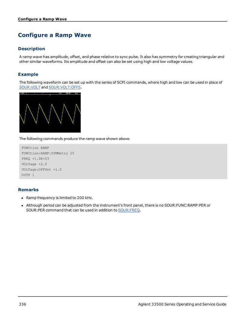
Configure a Ramp Wave
Configure a Ramp Wave
Description
A rampwave has amplitude, offset, and phase relative to sync pulse. It also has symmetry for creating triangular andother similar waveforms. Its amplitude and offset can also be set using high and low voltage values.
Example
The followingwaveform can be set upwith the series of SCPI commands, where high and low can be used in place ofSOUR:VOLT and SOUR:VOLT:OFFS.
The following commands produce the rampwave shown above.
FUNCtion RAMP
FUNCtion:RAMP:SYMMetry 25
FREQ +1.0E+03
VOLTage +2.0
VOLTage:OFFSet +1.0
OUTP 1
Remarks
l Ramp frequency is limited to 200 kHz.
l Although period can be adjusted from the instrument's front panel, there is no SOUR:FUNC:RAMP:PER orSOUR:PER command that can be used in addition to SOUR:FREQ.
336 Agilent 33500 Series Operating and Service Guide

Configure a Pulse Wave
Configure a Pulse Wave
Description
A pulse wave has amplitude, offset, and phase relative to sync pulse. It also adds edge slope, period, and duty cycle (orpulse width, depending on the FUNC:PULSe:HOLD configuration). Its amplitude and offset can also be set using highand low voltage values.
Example
The followingwaveform can be set upwith the series of SCPI commands, where high and low can be used in place ofSOUR:VOLT and SOUR:VOLT:OFFS.
The following commands produce the pulse wave shown above.
FUNC PULS
FUNC:PULS:TRAN:LEAD 4E-8
FUNC:PULS:TRAN:TRA 1E-6
FUNC:PULS:WIDT 3E-6
FREQ 2E5
VOLT 3
OUTP ON
Remarks
l You can use FUNC:PULS:PER instead of FREQ. These commands are paired; changing one changes the other.
l Pulse can be specified by width or duty cycle, which are also coupled. Use FUNCtion:PULSe:HOLD DCYC to specifythat duty cycle is held constant value as frequency or period changes. Use FUNCtion:PULSe:HOLDWIDTh to spec-ify that pulse width is held constant as frequency or period changes.
Agilent 33500 Series Operating and Service Guide 337

Create a List of Frequencies
Create a List of Frequencies
Description
The LIST commands set the instruments's output frequency according to entries in a frequency list, which allows fastchanging to frequencies in a list of up to 128 frequencies. The frequencies to be used are entered using theLIST:FREQuency command, or they may be read from a file usingMMEMory:LOAD:LIST[1|2].
Examples
The following code demonstrates the LIST:FREQuency method.
FUNCtion SQU
FREQuency:MODE LIST
LIST:DWELl +5.0E-03
LIST:FREQuency +1.0E+03,+3.0E+03,+7.0E+03
VOLTage +1.0
OUTPut 1
The results of this code are shown below.
338 Agilent 33500 Series Operating and Service Guide

Configure an arbitrary waveform
Configure an arbitrary waveformThis section describes the configuration of an arbitrary waveform.
Description
A user-created arbitrary waveform has amplitude, offset, sample rate, and filter type. These can be set when the arbi-trary waveform file (.arb or .barb extension) is loaded into waveform memory. The beginning of a typical arbitrarywaveform is shown below; note that amplitude and offset are represented by high and low voltage values:
File Format:1.10
Checksum:0
Channel Count:1
Sample Rate:20000.000000
High Level:2.000000
Low Level:0.000000
Marker Point:50
Data Type:"short"
Filter:"off"
Data Points:100
Data:
23259
23114
The 23259 and23114 lines after theData: line are ASCII DAC codes representing the first two waveform datavalues. If the waveform's DAC codes do not range from -32767 to + 32767, the output amplitude is asymmetric.
In firmware revisions 1.12 and before, the instrument did not update waveform metadata (sample rate, voltagerange, and filter setting) when switching from one arbitrary waveform to another. The new arbitrary waveformadopted the metadata of the waveform already in memory. Therefore, an arbitrary waveform designed to play at onevoltage range, sample rate, and filter setting (as specified in the waveform’s metadata) was changed to another set ofmetadata. After firmware revision 1.12, arbitrary waveforms load any metadata present in the arbitrary waveform file,so that they play the way they previously played.
Built-in waveformsmake few or no changes when loaded into waveform memory. They play according to the instru-ment’s current configuration. For example, see the beginning of Haversine.arb, shown below.
Copyright: Agilent Technologies, 2010
File Format:1.0
Channel Count:1
Data Points:40
Data:
0
202
802
Because of the missingmetadata, the current settings for voltage range, sample rate, and filter setup are used.
Example
The following code loads andmodifies a built-in arbitrary waveform.
Agilent 33500 Series Operating and Service Guide 339
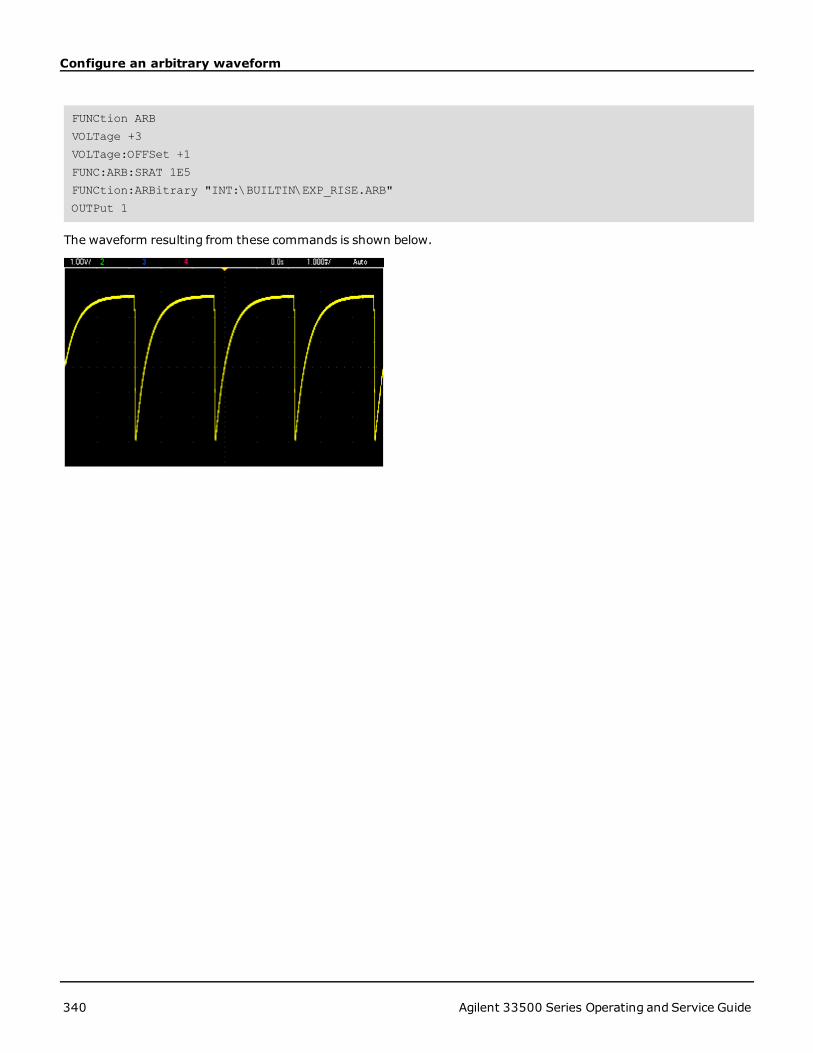
Configure an arbitrary waveform
FUNCtion ARB
VOLTage +3
VOLTage:OFFSet +1
FUNC:ARB:SRAT 1E5
FUNCtion:ARBitrary "INT:\BUILTIN\EXP_RISE.ARB"
OUTPut 1
The waveform resulting from these commands is shown below.
340 Agilent 33500 Series Operating and Service Guide

Agilent 33500 Series Command Quick Reference
Agilent 33500 Series Command Quick ReferenceSee the Syntax Conventions for SCPI.
APPLy Commands
[SOURce[1|2]:]APPLy?
[SOURce[1|2]:]APPLy: ARBitrary [{<sample_rate>|MIN|MAX|DEF} [,{<amplitude>|MIN|MAX|DEF} [,{<offset>|MIN|MAX|DEF}]]]
[SOURce[1|2]:]APPLy:DC [{<frequency>|DEF} [,{<amplitude>|DEF} [,{<offset>|MIN|MAX|DEF}]]]
[SOURce[1|2]:]APPLy:NOISe [{<frequency>|DEF} [,{<amplitude>|MIN|MAX|DEF} [,{<offset>|MIN|MAX|DEF}]]]
[SOURce[1|2]:]APPLy:PRBS [{<frequency>|DEF} [,{<amplitude>|MIN|MAX|DEF} [,{<offset>|MIN|MAX|DEF}]]]
[SOURce[1|2]:]APPLy:PULSe [{<frequency>|MIN|MAX|DEF} [,{<amplitude>|MIN|MAX|DEF} [,{<offset>|MIN|MAX|DEF}]]]
[SOURce[1|2]:]APPLy:RAMP [{<frequency>|MIN|MAX|DEF} [,{<amplitude>|MIN|MAX|DEF} [,{<offset>|MIN|MAX|DEF}]]]
[SOURce[1|2]:]APPLy:SINusoid [{<frequency>|MIN|MAX|DEF} [,{<amplitude>|MIN|MAX|DEF} [,{<offset>|MIN|MAX|DEF}]]]
[SOURce[1|2]:]APPLy:SQUare [{<frequency>|MIN|MAX|DEF} [,{<amplitude>|MIN|MAX|DEF} [,{<offset>|MIN|MAX|DEF}]]]
DATA Commands
DATA:ARB2:FORMat {AABB|ABAB}
[SOURce[1|2]:]DATA:ARBitrary[1|2] {<arb_name>}, {<binary_block> | <value>, <value>, . . .}
[SOURce[1|2]:]DATA:ARBitrary[1|2]:DAC {<arb_name>}, {<binary_block> | <value>, <value>, . . .}
[SOURce[1|2]:]DATA:ATTRibute:AVERage? [<arb_name>]
[SOURce[1|2]:]DATA:ATTRibute:CFACtor? [<arb_name>]
[SOURce[1|2]:]DATA:ATTRibute:POINts? [<arb_name>]
[SOURce[1|2]:]DATA:ATTRibute:PTPeak? [<arb_name>]
[SOURce[1|2]:]DATA:SEQuence <block_descriptor>
[SOURce[1|2]:]DATA:VOLatile:CATalog?
[SOURce[1|2]:]DATA:VOLatile:CLEar
[SOURce[1|2]:]DATA:VOLatile:FREE?
Output Configuration Commands
[SOURce[1|2]:]FUNCtion <function>
[SOURce[1|2]:]FUNCtion?
Agilent 33500 Series Operating and Service Guide 341

Agilent 33500 Series Command Quick Reference
FREQUENCY CONTROL
[SOURce[1|2]:]FREQuency {<frequency>|MINimum|MAXimum}
[SOURce[1|2]:]FREQuency? [{MINimum|MAXimum}]
[SOURce[1|2]:]FREQuency:CENTer {<frequency>|MINimum|MAXimum}
[SOURce[1|2]:]FREQuency:CENTer? [{MINimum|MAXimum}]
[SOURce[1|2]:]FREQuency:COUPle:MODE <mode>
[SOURce[1|2]:]FREQuency:COUPle:MODE?
[SOURce[1|2]:]FREQuency:COUPle:OFFSet <frequency>
[SOURce[1|2]:]FREQuency:COUPle:OFFSet?
[SOURce[1|2]:]FREQuency:COUPle:RATio <ratio>
[SOURce[1|2]:]FREQuency:COUPle:RATio?
[SOURce[1|2]:]FREQuency:COUPle[:STATe] <state>
[SOURce[1|2]:]FREQuency:COUPle[:STATe]?
[SOURce[1|2]:]FREQuency:MODE <mode>
[SOURce[1|2]:]FREQuency:MODE?
[SOURce[1|2]:]FREQuency:SPAN {<frequency>|MINimum|MAXimum}
[SOURce[1|2]:]FREQuency:SPAN? [{MINimum|MAXimum}]
[SOURce[1|2]:]FREQuency:STARt {<frequency>|MINimum|MAXimum}
[SOURce[1|2]:]FREQuency:STARt? [{MINimum|MAXimum}]
[SOURce[1|2]:]FREQuency:STOP {<frequency>|MINimum|MAXimum}
[SOURce[1|2]:]FREQuency:STOP? [{MINimum|MAXimum}]
FREQUENCY LIST MODE
[SOURce[1|2]:]LIST:DWELl {<seconds>|MINimum|MAXimum}
[SOURce[1|2]:]LIST:DWELl? [{MINimum|MAXimum}]
[SOURce[1|2]:]LIST:FREQuency <freq1>[,<freq2>, etc.]
[SOURce[1|2]:]LIST:FREQuency?
[SOURce[1|2]:]LIST:FREQuency:POINts? [{MINimum|MAXimum}]
MMEMory:LOAD:LIST[1|2] <filename>
MMEMory:STORe:LIST <filename>
VOLTAGE
[SOURce[1|2]:]VOLTage {<amplitude>|MINimum|MAXimum}
[SOURce[1|2]:]VOLTage? [{MINimum|MAXimum}]
[SOURce[1|2]:]VOLTage:COUPle[:STATe] <state>
342 Agilent 33500 Series Operating and Service Guide
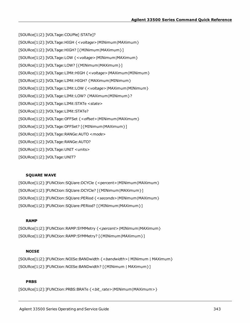
Agilent 33500 Series Command Quick Reference
[SOURce[1|2]:]VOLTage:COUPle[:STATe]?
[SOURce[1|2]:]VOLTage:HIGH {<voltage>|MINimum|MAXimum}
[SOURce[1|2]:]VOLTage:HIGH? [{MINimum|MAXimum}]
[SOURce[1|2]:]VOLTage:LOW {<voltage>|MINimum|MAXimum}
[SOURce[1|2]:]VOLTage:LOW? [{MINimum|MAXimum}]
[SOURce[1|2]:]VOLTage:LIMit:HIGH {<voltage>|MAXimum|MINimum}
[SOURce[1|2]:]VOLTage:LIMit:HIGH? {MAXimum|MINimum}
[SOURce[1|2]:]VOLTage:LIMit:LOW {<voltage>|MAXimum|MINimum}
[SOURce[1|2]:]VOLTage:LIMit:LOW? {MAXimum|MINimum}?
[SOURce[1|2]:]VOLTage:LIMit:STATe <state>
[SOURce[1|2]:]VOLTage:LIMit:STATe?
[SOURce[1|2]:]VOLTage:OFFSet {<offset>|MINimum|MAXimum}
[SOURce[1|2]:]VOLTage:OFFSet? [{MINimum|MAXimum}]
[SOURce[1|2]:]VOLTage:RANGe:AUTO<mode>
[SOURce[1|2]:]VOLTage:RANGe:AUTO?
[SOURce[1|2]:]VOLTage:UNIT <units>
[SOURce[1|2]:]VOLTage:UNIT?
SQUARE WAVE
[SOURce[1|2]:]FUNCtion:SQUare:DCYCle {<percent>|MINimum|MAXimum}
[SOURce[1|2]:]FUNCtion:SQUare:DCYCle? [{MINimum|MAXimum}]
[SOURce[1|2]:]FUNCtion:SQUare:PERiod {<seconds>|MINimum|MAXimum}
[SOURce[1|2]:]FUNCtion:SQUare:PERiod? [{MINimum|MAXimum}]
RAMP
[SOURce[1|2]:]FUNCtion:RAMP:SYMMetry {<percent>|MINimum|MAXimum}
[SOURce[1|2]:]FUNCtion:RAMP:SYMMetry? [{MINimum|MAXimum}]
NOISE
[SOURce[1|2]:]FUNCtion:NOISe:BANDwidth {<bandwidth>|MINimum |MAXimum}
[SOURce[1|2]:]FUNCtion:NOISe:BANDwidth? [{MINimum |MAXimum}]
PRBS
[SOURce[1|2]:]FUNCtion:PRBS:BRATe {<bit_rate>|MINimum|MAXimum>}
Agilent 33500 Series Operating and Service Guide 343

Agilent 33500 Series Command Quick Reference
[SOURce[1|2]:]FUNCtion:PRBS:BRATe? {<bit_rate>|MINimum|MAXimum}
[SOURce[1|2]:]FUNCtion:PRBS:DATA <sequence_type>
[SOURce[1|2]:]FUNCtion:PRBS:DATA?
[SOURce[1|2]:]FUNCtion:PRBS:TRANsition[:BOTH] {<seconds>|MINimum|MAXimum}
[SOURce[1|2]:]FUNCtion:PRBS:TRANsition[:BOTH]? [{MINimum|MAXimum}]
ARBITRARY WAVEFORM
[SOURce[1|2]:]FUNCtion:ARBitrary {<filename>}
[SOURce[1|2]:]FUNCtion:ARBitrary?
[SOURce[1|2]:]FUNCtion:ARBitrary:ADVance <mode>
[SOURce[1|2]:]FUNCtion:ARBitrary:ADVance?
[SOURce[1|2]:]FUNCtion:ARBitrary:FILTer <mode>
[SOURce[1|2]:]FUNCtion:ARBitrary:FILTer?
[SOURce[1|2]:]FUNCtion:ARBitrary:FREQuency {<frequency>|MINimum|MAXimum}
[SOURce[1|2]:]FUNCtion:ARBitrary:FREQuency? {MINimum|MAXimum}
[SOURce[1|2]:]FUNCtion:ARBitrary:PERiod {<period>|MINimum|MAXimum}
[SOURce[1|2]:]FUNCtion:ARBitrary:PERiod? {MINimum|MAXimum}
[SOURce[1|2]:]FUNCtion:ARBitrary:POINts?
[SOURce[1|2]:]FUNCtion:ARBitrary:SRATe {<sample_rate>|MINimum|MAXimum}
[SOURce[1|2]:]FUNCtion:ARBitrary:SRATe? {MINimum|MAXimum}
FUNCtion:ARBitrary:BALance[:STATe] <state> (IQ Player option only)
FUNCtion:ARBitrary:BALance[:STATe]? (IQ Player option only)
FUNCtion:ARBitrary:BALance:GAIN {<percent>|MINimum|MAXimum} (IQ Player option only)
FUNCtion:ARBitrary:BALance:GAIN? [MINimum|MAXimum} (IQ Player option only)
FUNCtion:ARBitrary:BALance:OFFSet[1|2]?{volts|MINimum|MAXimum} (IQ Player option only)
FUNCtion:ARBitrary:BALance:OFFSet[1|2]? [MINimum|MAXimum] (IQ Player option only)
FUNCtion:ARBitrary:SKEW[:STATe] <state> (IQ Player option only)
FUNCtion:ARBitrary:SKEW[:STATe]? (IQ Player option only)
FUNCtion:ARBitrary:SKEW:TIME <seconds> (IQ Player option only)
FUNCtion:ARBitrary:SKEW:TIME? (IQ Player option only)
[SOURce[1|2]:]RATE:COUPle:MODE <mode>
[SOURce[1|2]:]RATE:COUPle:MODE?
[SOURce[1|2]:]RATE:COUPle:OFFSet <sample_rate>
[SOURce[1|2]:]RATE:COUPle:OFFSet?
344 Agilent 33500 Series Operating and Service Guide

Agilent 33500 Series Command Quick Reference
[SOURce[1|2]:]RATe:COUPle:RATio <ratio>
[SOURce[1|2]:]RATe:COUPle:RATio?
[SOURce[1|2]:]RATE:COUPle[:STATe] <state>
[SOURce[1|2]:]RATE:COUPle[:STATe]?
OUTPUT
OUTPut[1|2] <state>
OUTPut[1|2]?
OUTPut[1|2]:LOAD {<ohms>|INFinity|MINimum|MAXimum}
OUTPut[1|2]:LOAD? [{MINimum|MAXimum}]
OUTPut[1|2]:MODE <mode>
OUTPut[1|2]:MODE?
OUTPut[1|2]:POLarity <polarity>
OUTPut[1|2]:POLarity?
OUTPut:SYNC<state>
OUTPut:SYNC?
OUTPut[1|2]:SYNC:MODE <mode>
OUTPut[1|2]:SYNC:MODE?
OUTPut[1|2]:SYNC:POLarity <polarity>
OUTPut[1|2]:SYNC:POLarity?
OUTPut:SYNC:SOURce <channel>
OUTPut:SYNC:SOURce?
OUTPut:TRIGger <state>
OUTPut:TRIGger?
OUTPut:TRIGger:SLOPe <slope>
OUTPut:TRIGger:SLOPe?
OUTPut:TRIGger:SOURce <channel>
OUTPut:TRIGger:SOURce?
Pulse Configuration Commands
[SOURce[1|2]:]FUNCtion:PULSe:DCYCle {<percent>|MINimum|MAXimum}
[SOURce[1|2]:]FUNCtion:PULSe:DCYCle? [{MINimum|MAXimum}]
[SOURce[1|2]:]FUNCtion:PULSe:HOLD <parameter>
[SOURce[1|2]:]FUNCtion:PULSe:HOLD?
Agilent 33500 Series Operating and Service Guide 345

Agilent 33500 Series Command Quick Reference
[SOURce[1|2]:]FUNCtion:PULSe:PERiod {<seconds>|MINimum|MAXimum}
[SOURce[1|2]:]FUNCtion:PULSe:PERiod? [{MINimum|MAXimum}]
[SOURce[1|2]:]FUNCtion:PULSe:TRANsition[:BOTH] {<seconds>|MINimum|MAXimum}
[SOURce[1|2]:]FUNCtion:PULSe:TRANsition:LEADing {<seconds>|MINimum|MAXimum}
[SOURce[1|2]:]FUNCtion:PULSe:TRANsition:LEADing? [{MINimum|MAXimum}]
[SOURce[1|2]:]FUNCtion:PULSe:TRANsition:TRAiling {<seconds>|MINimum|MAXimum}
[SOURce[1|2]:]FUNCtion:PULSe:TRANsition:TRAiling? [{MINimum|MAXimum}]
[SOURce[1|2]:]FUNCtion:PULSe:WIDTh {<seconds>|MINimum|MAXimum}
[SOURce[1|2]:]FUNCtion:PULSe:WIDTh? [{MINimum|MAXimum}]
Modulation Commands
AM
[SOURce[1|2]:]AM[:DEPTh] {<depth_in_percent>|MINimum|MAXimum}
[SOURce[1|2]:]AM[:DEPTh]? [{MINimum|MAXimum}]
[SOURce[1|2]:]AM:DSSC<mode>
[SOURce[1|2]:]AM:DSSC?
[SOURce[1|2]:]AM:INTernal:FREQuency {<frequency>|MINimum|MAXimum}
[SOURce[1|2]:]AM:INTernal:FREQuency? [{MINimum|MAXimum}]
[SOURce[1|2]:]AM:INTernal:FUNCtion <function>
[SOURce[1|2]:]AM:INTernal:FUNCtion?
[SOURce[1|2]:]AM:SOURce <source>
[SOURce[1|2]:]AM:SOURce?
[SOURce[1|2]:]AM:STATe <state>
[SOURce[1|2]:]AM:STATe?
FM
[SOURce[1|2]:]FM[:DEViation] {<peak_deviation_in_Hz>|MINimum|MAXimum}
[SOURce[1|2]:]FM[:DEViation]? [{MINimum|MAXimum}]
[SOURce[1|2]:]FM:INTernal:FREQuency {<frequency>|MINimum|MAXimum}
[SOURce[1|2]:]FM:INTernal:FREQuency? [{MINimum|MAXimum}]
[SOURce[1|2]:]FM:INTernal:FUNCtion <function>
[SOURce[1|2]:]FM:INTernal:FUNCtion?
[SOURce[1|2]:]FM:SOURce <source>
[SOURce[1|2]:]FM:SOURce?
346 Agilent 33500 Series Operating and Service Guide

Agilent 33500 Series Command Quick Reference
[SOURce[1|2]:]FM:STATe <state>
[SOURce[1|2]:]FM:STATe?
BPSK Commands
[SOURce[1|2]:]BPSK:SOURce <source>
[SOURce[1|2]:]BPSK:SOURce?
[SOURce[1|2]:]BPSK:STATe <state>
[SOURce[1|2]:]BPSK:STATe?
[SOURce[1|2]:]BPSK:INTernal:RATE {<modulating_frequency>|MINimum|MAXimum}
[SOURce[1|2]:]BPSK:INTernal:RATE? [{MINimum|MAXimum}]
[SOURce[1|2]:]BPSK[:PHASe] {<angle>|MINimum|MAXimum}
[SOURce[1|2]:]BPSK[:PHASe]? [{MINimum|MAXimum}]
PM
[SOURce[1|2]:]PM:SOURce <source>
[SOURce[1|2]:]PM:SOURce?
[SOURce[1|2]:]PM:STATe <state>
[SOURce[1|2]:]PM:STATe?
[SOURce[1|2]:]PM:DEViation {<deviation in degrees>|MINimum|MAXimum}
[SOURce[1|2]:]PM:DEViation? [{MINimum|MAXimum}]
[SOURce[1|2]:]PM:INTernal:FREQuency {<frequency>|MINimum|MAXimum}
[SOURce[1|2]:]PM:INTernal:FREQuency? [{MINimum|MAXimum}]
FSK
[SOURce[1|2]:]FSKey:FREQuency {<frequency>|MINimum|MAXimum}
[SOURce[1|2]:]FSKey:FREQuency? [{MINimum|MAXimum}]
[SOURce[1|2]:]FSKey:INTernal:RATE {<rate_in_Hz>|MINimum|MAXimum}
[SOURce[1|2]:]FSKey:INTernal:RATE? [{MINimum|MAXimum}]
[SOURce[1|2]:]FSKey:SOURce <source>
[SOURce[1|2]:]FSKey:SOURce?
[SOURce[1|2]:]FSKey:STATe <state>
[SOURce[1|2]:]FSKey:STATe?
PWM
Agilent 33500 Series Operating and Service Guide 347
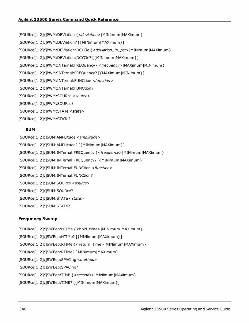
Agilent 33500 Series Command Quick Reference
[SOURce[1|2]:]PWM:DEViation {<deviation>|MINimum|MAXimum}
[SOURce[1|2]:]PWM:DEViation? [{MINimum|MAXimum}]
[SOURce[1|2]:]PWM:DEViation:DCYCle {<deviation_in_pct>|MINimum|MAXimum}
[SOURce[1|2]:]PWM:DEViation:DCYCle? [{MINimum|MAXimum}]
[SOURce[1|2]:]PWM:INTernal:FREQuency {<frequency>|MAXimum|MINimum}
[SOURce[1|2]:]PWM:INTernal:FREQuency? [{MAXimum|MINimum}]
[SOURce[1|2]:]PWM:INTernal:FUNCtion <function>
[SOURce[1|2]:]PWM:INTernal:FUNCtion?
[SOURce[1|2]:]PWM:SOURce <source>
[SOURce[1|2]:]PWM:SOURce?
[SOURce[1|2]:]PWM:STATe <state>
[SOURce[1|2]:]PWM:STATe?
SUM
[SOURce[1|2]:]SUM:AMPLitude <amplitude>
[SOURce[1|2]:]SUM:AMPLitude? [{MINimum|MAXimum}]
[SOURce[1|2]:]SUM:INTernal:FREQuency {<frequency>|MINimum|MAXimum}
[SOURce[1|2]:]SUM:INTernal:FREQuency? [{MINimum|MAXimum}]
[SOURce[1|2]:]SUM:INTernal:FUNCtion <function>
[SOURce[1|2]:]SUM:INTernal:FUNCtion?
[SOURce[1|2]:]SUM:SOURce <source>
[SOURce[1|2]:]SUM:SOURce?
[SOURce[1|2]:]SUM:STATe <state>
[SOURce[1|2]:]SUM:STATe?
Frequency Sweep
[SOURce[1|2]:]SWEep:HTIMe {<hold_time>|MINimum|MAXimum}
[SOURce[1|2]:]SWEep:HTIMe? [{MINimum|MAXimum}]
[SOURce[1|2]:]SWEep:RTIMe {<return_time>|MINimum|MAXimum}
[SOURce[1|2]:]SWEep:RTIMe? [ MINimum|MAXimum]
[SOURce[1|2]:]SWEep:SPACing<method>
[SOURce[1|2]:]SWEep:SPACing?
[SOURce[1|2]:]SWEep:TIME {<seconds>|MINimum|MAXimum}
[SOURce[1|2]:]SWEep:TIME? [{MINimum|MAXimum}]
348 Agilent 33500 Series Operating and Service Guide

Agilent 33500 Series Command Quick Reference
Burst Mode
[SOURce[1|2]:]BURSt:GATE:POLarity <polarity>
[SOURce[1|2]:]BURSt:GATE:POLarity?
[SOURce[1|2]:]BURSt:INTernal:PERiod {<seconds>|MINimum|MAXimum}
[SOURce[1|2]:]BURSt:INTernal:PERiod? [{MINimum|MAXimum}]
[SOURce[1|2]:]BURSt:MODE <method>
[SOURce[1|2]:]BURSt:MODE?
[SOURce[1|2]:]BURSt:NCYCles {<num_cycles>|INFinity|MINimum|MAXimum}
[SOURce[1|2]:]BURSt:NCYCles? [{MINimum|MAXimum}]
[SOURce[1|2]:]BURSt:PHASe {<angle>|MINimum|MAXimum}
[SOURce[1|2]:]BURSt:PHASe? [{MINimum|MAXimum}]
[SOURce[1|2]:]BURSt:STATe <state>
[SOURce[1|2]:]BURSt:STATe?
Trigger Setup
TRIGger[1|2]
TRIGger[1|2]:COUNt <number>
TRIGger[1|2]:COUNt?
TRIGger[1|2]:DELay {<seconds>|MINimum|MAXimum}
TRIGger[1|2]:DELay?
TRIGger[1|2]:SLOPe <slope>
TRIGger[1|2]:SLOPe?
TRIGger[1|2]:SOURce <source>
TRIGger[1|2]:SOURce?
TRIGger[1|2]:TIMer {<seconds>|MINimum|MAXimum}
TRIGger[1|2]:TIMer? {MINimum|MAXimum}
State Storage
MEMory:NSTates?
MEMory:STATe:CATalog?
MEMory:STATe:DELete <location>
MEMory:STATe:NAME {0|1|2|3|4} [,<name>]
Agilent 33500 Series Operating and Service Guide 349

Agilent 33500 Series Command Quick Reference
MEMory:STATe:NAME? {0|1|2|3|4}
MEMory:STATe:RECall:AUTO<mode>
MEMory:STATe:RECall:AUTO?
MEMory:STATe:VALid? <location>
Mass Memory
MMEMory:CATalog[:ALL]? [<folder>]
MMEMory:CATalog:DATA:ARBitrary? [<folder>]
MMEMory:CATalog:STATe? [<folder>]
MMEMory:CDIRectory <folder>
MMEMory:MDIRectory <folder>
MMEMory:RDIRectory <folder>
MMEMory:COPY <file1>,<file2>
MMEMory:COPY:SEQuence <source>,<destination>
MMEMory:DELete <file>
MMEMory:DOWNload:DATA <binary_block>
MMEMory:DOWNload:FNAMe <filename>
MMEMory:LOAD:ALL <filename>
MMEMory:LOAD:DATA[1|2] <filename>
MMEMory:LOAD:LIST[1|2] <filename>
MMEMory:LOAD:STATe <filename>
MMEMory:MOVE <file1>,<file2>
MMEMory:STORe:ALL <filename>
MMEMory:STORe:DATA[1|2] <filename>
MMEMory:STORe:LIST <filename>
MMEMory:STORe:STATe <filename>
MMEMory:UPLoad? <filename>
System
DISPlay <mode>
DISPlay?
DISPlay:TEXT <string>
DISPlay:TEXT?
350 Agilent 33500 Series Operating and Service Guide

Agilent 33500 Series Command Quick Reference
DISPlay:TEXT:CLEar
HCOPy:SDUMp:DATA?
HCOPy:SDUMp:DATA:FORMat <graphics_format>
HCOPy:SDUMp:DATA:FORMat?
LXI
LXI:IDENtify[:STATE] <state>
LXI:IDENtify[:STATE]?
LXI:MDNS:ENABle <state>
LXI:MDNS:ENABle?
LXI:MDNS:HNAMe:RESolved?
LXI:MDNS:SNAMe:DESired <name>
LXI:MDNS:SNAMe:DESired?
LXI:MDNS:SNAMe:RESolved?
LXI:RESet
LXI:RESTart
Remote Interface Configuration
SYSTem:BEEPer[:IMMediate]
SYSTem:BEEPer:STATe <mode>
SYSTem:BEEPer:STATe?
SYSTem:COMMunicate:ENABle <state>, <interface>
SYSTem:COMMunicate:ENABle? <interface>
SYSTem:COMMunicate:GPIB:ADDRess {<address>}
SYSTem:COMMunicate:GPIB:ADDRess?
SYSTem:COMMunicate:LAN:CONTrol?
SYSTem:COMMunicate:LAN:DHCP <state>
SYSTem:COMMunicate:LAN:DHCP?
SYSTem:COMMunicate:LAN:DNS[1|2] "<address>"
SYSTem:COMMunicate:LAN:DNS[1|2]? [{CURRent | STATic}]
SYSTem:COMMunicate:LAN:DOMain?
SYSTem:COMMunicate:LAN:GATeway "<address>"
SYSTem:COMMunicate:LAN:GATeway? [{CURRent | STATic}]
Agilent 33500 Series Operating and Service Guide 351

Agilent 33500 Series Command Quick Reference
SYSTem:COMMunicate:LAN:HOSTname "<name>"
SYSTem:COMMunicate:LAN:HOSTname? [{CURRent | STATic}]
SYSTem:COMMunicate:LAN:IPADdress "<address>"
SYSTem:COMMunicate:LAN:IPADdress? [{CURRent | STATic}]
SYSTem:COMMunicate:LAN:MAC?
SYSTem:COMMunicate:LAN:SMASk "<mask>"
SYSTem:COMMunicate:LAN:SMASk? [{CURRent | STATic}]
SYSTem:COMMunicate:LAN:TELNet:PROMpt "<string>"
SYSTem:COMMunicate:LAN:TELNet:PROMpt?
SYSTem:COMMunicate:LAN:TELNet:WMESsage "<string>"
SYSTem:COMMunicate:LAN:TELNet:WMESsage?
SYSTem:COMMunicate:LAN:UPDate
SYSTem:COMMunicate:LAN:WINS[1|2] "<address>"
SYSTem:COMMunicate:LAN:WINS[1|2]? [{CURRent | STATic}]
SYSTem:DATE <yyyy>, <mm>, <dd>
SYSTem:DATE?
SYSTem:ERRor?
SYSTem:LICense:CATalog?
SYSTem:LICense:DELete <option_name>
SYSTem:LICense:DELete:ALL
SYSTem:LICense:DESCription? "<option_name>"
SYSTem:LICense:ERRor?
SYSTem:LICense:ERRor:COUNt?
SYSTem:LICense:INSTall [{<folder> |<file>}]
SYSTem:LICense:INSTall? <option>
SYSTem:LOCK:NAME?
SYSTem:LOCK:OWNer?
SYSTem:LOCK:RELease
SYSTem:LOCK:REQuest?
SYSTem:SECurity:IMMediate
SYSTem:TIME <hh>, <mm>, <ss>
SYSTem:TIME?
SYSTem:VERSion?
352 Agilent 33500 Series Operating and Service Guide

Agilent 33500 Series Command Quick Reference
Phase-Lock
[SOURce[1|2]:]PHASe {<angle>|MINimum|MAXimum}
[SOURce[1|2]:]PHASe? [{MINimum|MAXimum}]
[SOURce[1|2]:]PHASe:REFerence
[SOURce[1|2]:]PHASe:SYNChronize
[SOURce[1|2]:]PHASe:UNLock:ERRor:STATe <mode>
[SOURce[1|2]:]PHASe:UNLock:ERRor:STATe?
ROSCillator:SOURce <source>
ROSCillator:SOURce?
ROSCillator:SOURce:AUTO<state>
ROSCillator:SOURce:AUTO?
ROSCillator:SOURce:CURRent?
Calibration
CALibration?
CALibration:COUNt?
CALibration:SECure:CODE <new_code>
CALibration:SECure:STATe <mode>, <code>
CALibration:SECure:STATe?
CALibration:SETup<step_number>
CALibration:SETup?
CALibration:STRing "<quoted_string>"
CALibration:STRing?
CALibration:VALue <measurement>
CALibration:VALue?
IEEE-488
*CLS
*ESR?
*IDN?
*OPC
*OPC?
Agilent 33500 Series Operating and Service Guide 353

Agilent 33500 Series Command Quick Reference
*OPT?
*PSC<mode>
*PSC?
*RCL <state_storage_location>
*RST
*SAV <state_storage_location>
*SRE <enable_value>
*SRE?
*STB?
*TRG
*TST?
Status
STATus:OPERation:CONDition?
STATus:OPERation:ENABle <enable_value>
STATus:OPERation:ENABle?
STATus:OPERation[:EVENt]?
STATus:QUEStionable:CONDition?
STATus:QUEStionable:ENABle <enable_value>
STATus:QUEStionable:ENABle?
Miscellaneous
ABORt
[SOURce[1|2]:]COMBine:FEED <source>
[SOURce[1|2]:]COMBine:FEED?
FORMat:BORDer <byte_order>
FORMat:BORDer?
INITiate[1|2]:CONTinuous <state>
INITiate[1|2]:CONTinuous?
INITiate:CONTinuous:ALL <state>
INITiate[1|2][:IMMediate]
INITiate:IMMediate:ALL
[SOURce[1|2]:]MARKer:CYCLe {<cycle_num>|MINimum|MAXimum}
354 Agilent 33500 Series Operating and Service Guide

Agilent 33500 Series Command Quick Reference
[SOURce[1|2]:]MARKer:CYCLe? [{MINimum|MAXimum}]
[SOURce[1|2]:]MARKer:FREQuency {<frequency>|MINimum|MAXimum}
[SOURce[1|2]:]MARKer:FREQuency? [{MINimum|MAXimum}]
[SOURce[1|2]:]MARKer:POINt {<sample_number>|MINimum|MAXimum}
[SOURce[1|2]:]MARKer:POINt? [{MINimum|MAXimum}]
[SOURce[1|2]:]TRACk <track_mode>
UNIT:ANGLe <units> UNIT:ANGLe?
Agilent 33500 Series Operating and Service Guide 355

Factory Reset State
Factory Reset StateThe following tables show factory default settings. Parameters markedwith a bullet (•) are non-volatile, and are notaffected by power cycling or *RST. Other parameters are volatile and reset to the indicated values at power-on or after*RST.
The power-on/reset state may differ from that shown below if you have enabled power-on staterecall mode from the [System]menu. See Instrument State Storage.
Output Channel Configuration
Function Sine Wave
Tracking Off
Frequency 1 kHz
Frequency Mode CW
Frequency CoupleState
OFF
Frequency CoupleMode
Ratio
Frequency CoupleRatio
1
Frequency Couple Off-set
0
Amplitude 100 mVpp
Offset 0 VDC
Voltage Couple State OFF
Voltage Limit State OFF
Voltage Limit High 5 V
Voltage Limit Low -5 V
Voltage Unit VPP
Voltage Range AUTO
State OFF
Load 50 Ω
Polarity Normal
356 Agilent 33500 Series Operating and Service Guide

Factory Reset State
Mode (Normal vs.Gated)
Normal
Sync Polarity Normal
Sync Mode Normal
Output Channel Configuration
Sync State ON
Sync Source CH1
Trigger Source CH1
Trigger Slope Positive
Trigger State OFF
Noise
Bandwidth 100 kHz
PRBS
Data PN7
Bit Rate 1 kbps
Transition 8.4E-09
Pulse
Duty Cycle 10%
Period 1 ms
Leading/Trailing Edge 10 ns
Width 0.1 ms
Ramp
Symmetry 100
Square
Duty Cycle 50%
Period 1 ms
Arbitrary Waveforms
Arb Exponential Rise
Agilent 33500 Series Operating and Service Guide 357

Factory Reset State
Filter STEP
Sample Rate 40 kSa/sec
Advance SRATE
Marker Point Mid point of arb
Amplitude Modulation
State OFF
Modulation Source Internal
Internal Function Sine Wave
Internal Frequency 100 Hz
Depth 100%
DSSC OFF
Frequency Modulation
State OFF
Modulation Source Internal
Internal Function Sine Wave
Internal Frequency 10 Hz
Deviation 100 Hz
FSK Modulation
State OFF
Modulation Source Internal
Internal Rate 10 Hz
Frequency 100 Hz
Phase Modulation
State OFF
Modulation Source Internal
Function Sine Wave
Frequency 10 Hz
358 Agilent 33500 Series Operating and Service Guide
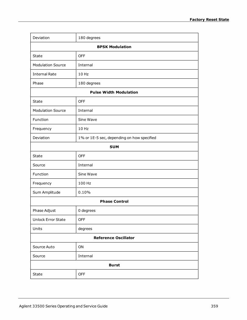
Factory Reset State
Deviation 180 degrees
BPSK Modulation
State OFF
Modulation Source Internal
Internal Rate 10 Hz
Phase 180 degrees
Pulse Width Modulation
State OFF
Modulation Source Internal
Function Sine Wave
Frequency 10 Hz
Deviation 1% or 1E-5 sec, depending on how specified
SUM
State OFF
Source Internal
Function Sine Wave
Frequency 100 Hz
Sum Amplitude 0.10%
Phase Control
Phase Adjust 0 degrees
Unlock Error State OFF
Units degrees
Reference Oscillator
Source Auto ON
Source Internal
Burst
State OFF
Agilent 33500 Series Operating and Service Guide 359

Factory Reset State
Gate Polarity Normal
Mode Triggered
Cycles 1
Period 10 ms
Phase 0 degrees
Marker Cycle 2
Sweep
State OFF
Spacing Linear
Start Freq 100 Hz
Stop Freq 1 kHz
Center Freq 550 Hz
Span 900 Hz
Marker Freq 500 Hz
Sweep Time 1 sec
Hold Time 0 sec
Return Time 0 sec
List
Frequency 100, 1000, 550 Hz
Points 3
Dwell 1 sec
Trigger
Delay 0 sec
Slope Positive
Source Immediate
Timer 1 sec
Init Continuous ON
360 Agilent 33500 Series Operating and Service Guide

Factory Reset State
Count 1
Channel Independent Trigger Configuration
Init Continuous All ON
Miscellaneous
Format Byte Order Normal
Combine Feed NONE
The following items do not relate to channel configuration.
Display
State ON
Text ""
Hcopy Format PNG
Remote Interface Communication
GPIB Address • 10
DHCP • Enabled
IP Address static • 169.254.5.21
Subnet Mask static • 255.255.0.0
Gateway static • 0.0.0.0
DNS primary server • 0.0.0.0
DNS secondary server•
0.0.0.0
Hostname static • "A-335xxx-nnnnn" or "A-335xxx-nnnnn", where xxx is the lastthree digits of the model number, and nnnnn is the last 5 digits ofthe instrument's serial number
Telnet Prompt • 335xxx>, where xxx is the last three digits of the model number.
Telent Welcome Mes-sage •
Welcome to Agilent's 335xxx Waveform Generator, where xxx isthe last three digits of the model number.
WINS primary server • 0.0.0.0
Agilent 33500 Series Operating and Service Guide 361

Factory Reset State
WINS secondaryserver •
0.0.0.0
System
Beep State ON
Power Down Recall • OFF
LXI
Identify OFF
Calibration
Calibration State Secured
The instrument uses LAN port 5024 for SCPI Telnet sessions, and port5025 for SCPI Socket sessions.
362 Agilent 33500 Series Operating and Service Guide

SCPI Error Messages
SCPI Error MessagesThe instrument returns error messages in accord with the SCPI standard.
l Up to 20 errors can be stored in each interface-specific error queue (one each for GPIB, USB, VXI-11, and Tel-net/Sockets.) Errors appear in the error queue of the I/O session that caused the error.
l The instrument beeps once each time a command syntax or hardware error is generated. The front-panel ERRORannunciator turns on when one or more errors are in the error queue.
l A special global error queue holds all power-on and hardware-related errors (for example, over-temperature).
l Error retrieval is first-in-first-out (FIFO), and errors are cleared as you read them. Once you have read all interface-specific errors, the errors in the global error queue are retrieved. When you have read all errors from the globalerror queue, the ERROR annunciator turns off.
l If more than 20 errors have occurred, the last error stored in the queue (the most recent error) is replacedwith -350,"Error queue overflow". No additional errors are stored until you remove errors from the queue. If no errorshave occurred when you read the error queue, the instrument responds with +0,"No error".
l The front panel reports errors from all I/O sessions and the global error queue. To read the error queue from thefront panel, press the [System] button, then theHelp softkey. Then select "View remote command error queue"in the Helpmenu.
l Error conditions are also summarized in the Status Byte Register. See Status Subsystem Introduction for details
l The interface-specific error queues are cleared by power cycles and *CLS. The error queue is not cleared by *RST.
l SCPI:
SYSTem:ERRor? Read and clear one error from the queue
Errors have the following format (the error stringmay contain up to 255 characters):
-113,"Undefined header"
-315 Configuration memory lost; due to firmware revision change
-315 Configuration memory lost;memory corruption detected
-314 Save/recall memory lost; due to firmware revision change
-314 Save/recall memory lost;memory corruption detected
-313 Calibration memory lost
-313 Calibration memory lost; due to firmware revision change
-313 Cannot read file; due to corrupt data
-313 Cannot read file; due to file revision change
-313 Invalid number of channels for operation
-310 System error; internal software error
-310 System error; out of memory
-310 System error; software initialization failed
-292 Referenced name does not exist
-257 File name error;
Agilent 33500 Series Operating and Service Guide 363

SCPI Error Messages
access denied
drive namemissing or not recognized
file or folder already exists
file too large
folder is default folder
folder not empty
invalid character in name
not a folder name
path is a folder name
path namemissing
path too long
relative path not allowed
unknown file extension
-256 File or folder name not found
-254 Media full
-252 Missingmedia
-250 Mass storage error: file read/write error
-241 Hardware missing
-241 Hardware missing; Command not valid in one channel instrument.
-240 Hardware error; GPIB interface failed
-230 Data corrupt or stale
-222 Data out of range;
AM depth
amplitude
arb frequency
arb period
burst count
burst count limited by length of burst
burst period
burst period limited by length of burst
cannot combine channel with itself. Combine disabled
duty cycle
duty cycle limited by frequency
364 Agilent 33500 Series Operating and Service Guide

SCPI Error Messages
FM deviation
FM deviation limited by maximum frequency
FM deviation limited by minimum frequency
frequency
frequency in burst mode
high level limited by high soft limit
high level limited by low level
high level limited by low soft limit
high limit value limited by high signal level
large period limits minimum pulse width
low level limited by high level
low level limited by high soft limit
low level limited by low soft limit
low limit value limited by low signal level
marker confined to burst cycles
marker confined to sweep span
offset
period
PRBS edge time
PRBS edge time limited by bit rate
pulse duty cycle limited by period
pulse edge at maximum
pulse edge at minimum
pulse edge time
pulse edge time limited by duty cycle
pulse edge time limited by period
pulse edge time limited by width
pulse frequency
pulse period
pulse width
pulse width limited by period
PWM deviation
PWM deviation limited by pulse parameters
ramp frequency
Agilent 33500 Series Operating and Service Guide 365

SCPI Error Messages
ramp Symmetry
Sample rate
sample rate clipped to lower limit
sample rate clipped to upper limit
quare edge time
square edge time limited by duty cycle
square edge time limited by period
square edge time limited by width
square period
square width
sum amplitude limited by channel or combine amplitudes
sum amplitude value clipped to lower limit
sweep time
Track exceeds limits on channel 1. Tracking disabled
Track exceeds limits on channel 2. Tracking disabled
trigger count clipped to lower limit
trigger count clipped to upper limit
trigger delay
trigger delay clipped to lower limit
trigger delay clipped to upper limit
trigger delay limited by length of burst
trigger timer clipped to lower limit
trigger timer clipped to upper limit
trigger timer limited by length of burst
user frequency
USER setting only valid for channel 1
value clipped to dwell time's lower limit
value clipped to dwell time's upper limit
value clipped to lower limit
value clipped to sweep time's lower limit
value clipped to upper limit
value limited due to coupling
-222 List Data out of range; pulse frequency : Mode is changed to continuous wave
-222 List Data out of range; ramp frequency : Mode is changed to continuous wave
366 Agilent 33500 Series Operating and Service Guide

SCPI Error Messages
-222 List Data out of range; Sine frequency : Mode is changed to continuous wave
-222 List Data out of range; Square frequency : Mode is changed to continuous wave
-222 List Data out of range; user frequency : Mode is changed to continuous wave
-221 Setting the advance mode to trigger forced the trigger source to external.
-221 Setting the Arb Filter OFF changed the maximum sample rate value to 6.25e7.
-221 Setting the trigger source changed the arb advance mode.
-221 Settings conflict;
50V input range not compatible with 50 ohm input impedance; impedance set to 1 Mohm
AM depth forced amplitude change
AM turned off by selection of other mode or modulation
amplitude changed due to function
amplitude changed due to offset
amplitude units changed to Vpp due to high-Z load
amplitude units changed to Vpp, dBm and Vrms not applicable to arb sequences
amplitude units unchanged, dBm and Vrms not applicable to arb sequences
arb advance changed to SRATE due tomode
arb voltage reduced due to output load or limits
both edge times decreased due to period
both edge times decreased due to pulse duty cycle
both edge times decreased due to pulse width
BPSK turned off by selection of other mode or modulation
burst count reduced to fit entire burst
Burst mode has caused output phase to be set to zero degrees
burst period increased to fit entire burst
burst phase inapplicable for arbs larger than 1M. burst phase set to 0
burst turned off by selection of other mode or modulation
cannot delete state selected and enabled for automatic power-on recall
Cannot modulate ARB carrier with ARB asmodulation function. Modulation turned off.
Cannot modulate ARB carrier with ARBmodulation function. Function unchanged.
Cannot modulate ARB carrier with USER asmodulation function. Modulation turned off.
Cannot modulate ARB carrier with USERmodulation function. Function unchanged.
Cannot modulate Noise carrier with Noise as modulation function. Modulation turned off.
Cannot modulate Noise carrier with Noise modulation function. Function unchanged.
Cannot modulate PRBS carrier with PRBS asmodulation function. Modulation turned off.
Agilent 33500 Series Operating and Service Guide 367

SCPI Error Messages
Cannot modulate PRBS carrier with PRBSmodulation function. Function unchanged.
Cannot modulate USER carrier with ARB asmodulation function. Modulation turned off.
Cannot modulate USER carrier with ARBmodulation function. Function unchanged.
Cannot modulate USER carrier with USER asmodulation function. Modulation turned off.
Cannot modulate USER carrier with USERmodulation function. Function unchanged.
combine amplitude exceeds limit. Combine disabled
coupling cannot be ON with this function, coupling turned off
coupling violates settings, coupling turned off
edge time decreased due to bit rate
external gating not compatible with gate output; gate output disabled
FM deviation cannot exceed carrier
FM deviation exceedsmaximum frequency
FM turned off by selection of other mode or modulation
frequency changed for pulse function
frequency forced duty cycle change
frequency made compatible with burst mode
frequency reduced for ramp function
frequency reduced for user function
FSK turned off by selection of other mode or modulation
Function or modulation source cannot be USER. Tracking disabled
Function selection limited the FSK frequency.
Gated output not available for gated burst. Output mode changed to normal.
high level changed due to low level
high limit less than low limit. Limits disabled
infinite burst changed trigger source to BUS
input threshold voltage > input range; threshold clipped to range
leading edge time decreased due to period
leading edge time decreased due to pulse width
leading edge times decreased due to pulse duty cycle
limited frequency to 1MHz when syncmode carrier, burst ON, and function sine
list turned off by selection of other mode or modulation
low level changed due to high level
low reference >= high reference
marker forced into sweep span
368 Agilent 33500 Series Operating and Service Guide

SCPI Error Messages
marker off forced sync to normal mode
marker on forced sync to marker mode
marker point changed to fit arb length
modulation frequency made compatible with modulation shape
must stop operation to update trigger count
must stop operation to update trigger delay
not able to adjust phase in this function
not able to adjust phase in this mode
not able to burst DC, burst turned off
not able to burst this function
not able to change output loadwith limits enabled
not able to list arb, list turned off
not able to list DC, list turned off
not able to list noise, list turned off
not able to list PRBS, list turned off
not able to list this function
not able to modulate arb, modulation turned off
not able to modulate DC,modulation turned off
not able to modulate noise, modulation turned off
not able to modulate PRBS,modulation turned off
not able to modulate this function
not able to sweep arb, sweep turned off
not able to sweep DC, sweep turned off
not able to sweep noise, sweep turned off
not able to sweep PRBS, sweep turned off
not able to sweep this function
offset changed due to amplitude
offset changed on exit from DC function
PM turned off by selection of other mode or modulation
pulse duty cycle decreased due to period
pulse duty cycle increased due to period
pulse width decreased due to period
pulse width increased due to large period
PWM deviation decreased due to pulse parameters
Agilent 33500 Series Operating and Service Guide 369

SCPI Error Messages
PWM only available in pulse function
PWM turned off by selection of other mode or modulation
selected arb is missing, changing selection to default
selecting a sequence turned off modulation
sequences not supported, changing selection to default
signal exceeds high limit. Limits disabled
signal exceeds low limit. Limits disabled
sum amplitude exceeds limit or range. Sum disabled
SUM turned off by selection of other mode or modulation
Sweep+ Hold + Return time larger than trigger TIMER. Trig timer increased.
Sweep+ Hold + Return timemax (8000s) limited time setting.
Sweep+ Hold + Return time too large for IMM or TIMER trigger. Sweep turned off.
Sweep+ Hold + Return time too large for IMM or TIMER trigger. Trig source unchanged.
Sweep time reduced due to log sweep setting.
sweep turned off by selection of other mode or modulation
Tracking turned off by selection of USER function or modulation source
trailing edge decreased due to leading edge
trailing edge time decreased due to period
trailing edge time decreased due to pulse width
trailing edge times decreased due to pulse duty cycle
trigger delay reduced to fit entire burst
trigger output connector used by BPSK
trigger output connector used by burst gate
trigger output connector used by FSK
trigger output connector used by trigger external
trigger output disabled
trigger output disabled by trigger external
Trigger source limited the sweep time; value clipped to upper limit
triggered burst not available for noise
turned off infinite burst to allow immediate trigger source
Use FUNC:ARB to select an ARB before selecting ARB asmodulation function. Function unchanged.
Use FUNC:ARB to select an ARB before selecting ARB asmodulation function. Modulation disabled.
Use FUNC:USER to select a user arb before selecting USER asmodulation function. Function unchanged.
Use FUNC:USER to select a user arb before selecting USER asmodulation function. Modulation disabled.
370 Agilent 33500 Series Operating and Service Guide

SCPI Error Messages
-213 INIT ignored
-115 Invalid parameter; Parameter not supported on one channel instrument
-114 Header suffix out of range
100 Network Error
110 LXI mDNS Error
201 Memory lost: stored state
202 Memory lost: power-on state
203 Memory lost: storedmeasurements
263 Not able to execute while instrument is measuring
291 Not able to recall state: it is empty
292 State file size error
293 State file corrupt
301 Cannot reset input protection; high voltage present
305 Not able to perform requested operation
514 Not allowed
514 Not allowed; Instrument locked by another I/O session
521 Communications: input buffer overflow
522 Communications: output buffer overflow
532 Not able to achieve requested resolution
540 Cannot use overload as math reference
550 Not able to execute command in local mode
560 No valid external timebase
561 High voltage present on input channel
570 DDS Processor is not responding
580 Reference phase-locked loop is unlocked
600 Internal licensing error
601 License file corrupt or empty
601 Self-test failed
602 No valid licenses found for this instrument
602 Self-test failed
603 Self-test failed
603 Some licenses could not be installed
604 License not found
604 Self-test failed
Agilent 33500 Series Operating and Service Guide 371

SCPI Error Messages
605 Self-test failed
606 Self-test failed
607 Self-test failed
608 Self-test failed
609 Self-test failed
610 Self-test failed
611 Self-test failed
612 Self-test failed
613 Self-test failed
615 Self-test failed
616 Self-test failed
620 Self-test failed
621 Self-test failed
625 Self-test failed
630 Self-test failed
631 Self-test failed
635 Self-test failed
640 Self-test failed
650 Self-test failed
655 Self-test failed
660 Self-test failed
701 Calibration error; security defeated by hardware jumper
702 Calibration error; calibration memory is secured
703 Calibration error; secure code providedwas invalid
704 Calibration error: secure code too long
705 Calibration error; calibration aborted
706 Calibration error; provided value is out of range
707 Calibration error: computed correction factor out of range
707 Calibration error; signal input is out of range
708 Calibration error: signal measurement out of range
709 Calibration error: no calibration for this function
710 Calibration error: full scale correction out of range
710 Self-calibration failed
711 Calibration error: calibration string too long
372 Agilent 33500 Series Operating and Service Guide

SCPI Error Messages
711 Self-calibration failed
712 Calibration failed
712 Self-calibration failed
715 Self-calibration failed
720 Self-calibration failed
740 Calibration data lost: secure state
741 Calibration data lost: string data
742 Calibration data lost: corrections
748 Calibration memory write failure
770 Nonvolatile arb waveform memory corruption detected
781 Not enough memory to store new arb waveform; bad sectors
781 Not enough memory to store new arb waveform; use DATA:DELETE
782 Cannot overwrite a built-in arb waveform
784 Name of source arb waveform for copy must be VOLATILE
785 Specified arb waveform does not exist
786 Not able to delete a built-in arb waveform
786 Specified arb waveform already exists
787 Not able to delete the currently selected active arb waveform
787 Specified arb not loaded in waveform memory
788 Could not load specified arb; Loaded Built-in default arb
791 Firmware update error; unable to begin download
792 Firmware update error; programming operation failed
793 Firmware update error; data record invalid character
794 Firmware update error; data record length mismatch
795 Firmware update error; data record checksum mismatch
796 Firmware update error; bad checksum for download start
797 Firmware update error; bad checksum for download complete
798 Firmware update error; download in progress
799 Firmware update error; unable to complete download
800 Firmware update error; invalid programming address
810 State has not been stored
811 Method not implemented, YET!
850 Calibration error; set up is invalid
851 Calibration error; set up is out of order
Agilent 33500 Series Operating and Service Guide 373
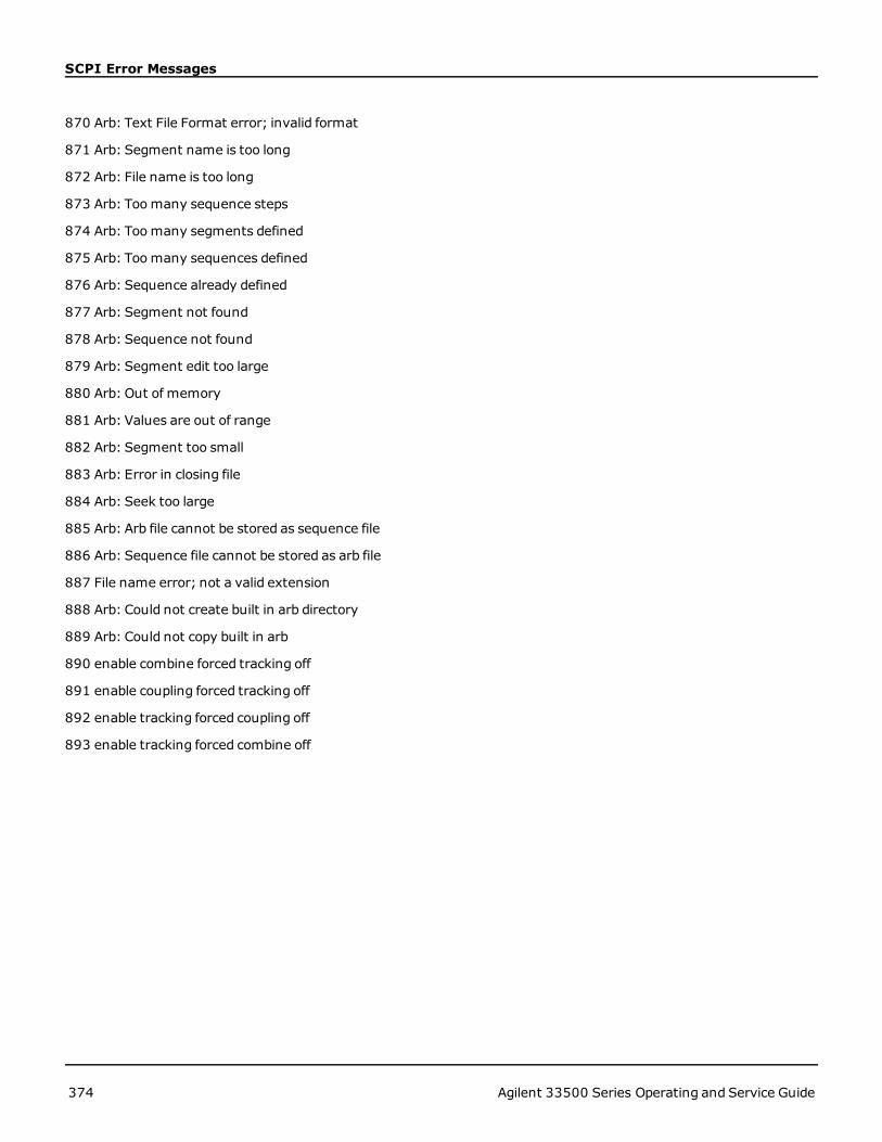
SCPI Error Messages
870 Arb: Text File Format error; invalid format
871 Arb: Segment name is too long
872 Arb: File name is too long
873 Arb: Toomany sequence steps
874 Arb: Toomany segments defined
875 Arb: Toomany sequences defined
876 Arb: Sequence already defined
877 Arb: Segment not found
878 Arb: Sequence not found
879 Arb: Segment edit too large
880 Arb: Out of memory
881 Arb: Values are out of range
882 Arb: Segment too small
883 Arb: Error in closing file
884 Arb: Seek too large
885 Arb: Arb file cannot be stored as sequence file
886 Arb: Sequence file cannot be stored as arb file
887 File name error; not a valid extension
888 Arb: Could not create built in arb directory
889 Arb: Could not copy built in arb
890 enable combine forced tracking off
891 enable coupling forced tracking off
892 enable tracking forced coupling off
893 enable tracking forced combine off
374 Agilent 33500 Series Operating and Service Guide

Service and Repair - Introduction
Service and Repair - IntroductionThis section contains basic service information for your instrument.
Types of Service Available
Cleaning
Electrostatic Discharge (ESD) Precautions
Surface Mount Repair
Additional service information is found here:
Block Diagram
Power Supplies
Troubleshooting
Self-Test Procedures
Replaceable Parts
Disassembly
Types of Service Available
If your instrument fails during the warranty period, Agilent Technologies will repair or replace it under the terms of yourwarranty. After your warranty expires, Agilent offers repair services at competitive prices.
Extended Service Contracts
Many Agilent products have optional service contracts that extend coverage after the standard warranty expires.
Obtaining Repair Service (Worldwide)
To obtain service for your instrument, contact your nearest Agilent Technologies Service Center. They will arrange tohave your unit repaired or replaced, and can provide warranty or repair–cost information where applicable. Ask the Agi-lent Technologies Service Center for shipping instructions, including what components to ship. Agilent recommendsthat you retain the original shipping carton for return shipments.
Repackaging for Shipment
To ship the unit to Agilent for service or repair:
l Attach a tag to the unit identifying the owner and indicating the required service or repair. Include the modelnumber and full serial number.
l Place the unit in its original container with appropriate packagingmaterial.
l Secure the container with strong tape or metal bands.
l If the original shipping container is unavailable, use a container that will ensure at least 10 cm (4 in.) of com-pressible packagingmaterial around the entire instrument. Use static-free packagingmaterials.
Agilent suggests that you always insure shipments.
Agilent 33500 Series Operating and Service Guide 375
Service and Repair - Introduction
Cleaning
Clean the outside of the instrument with a soft, lint-free, slightly damp cloth. Do not use detergent. Disassembly is notrequired or recommended for cleaning.
Electrostatic Discharge (ESD) Precautions
Almost all electrical components can be damaged by electrostatic discharge (ESD) during handling. Component damagecan occur at electrostatic discharge voltages as low as 50 V.
The following guidelines will help prevent ESD damage during service operations:
l Disassemble instruments only in a static-free work area.
l Use a conductive work area to reduce static charges.
l Use a conductive wrist strap to reduce static charge accumulation.
l Minimize handling.
l Keep replacement parts in original static-free packaging.
l Remove all plastic, foam, vinyl, paper, and other static-generatingmaterials from the immediate work area.
l Use only anti-static solder suckers.
Surface Mount Repair
Surface mount components should only be removed using equipment designed for surface mount components. Usingconventional soldering equipment will almost always damage to the printed circuit board andwill void your warranty.
376 Agilent 33500 Series Operating and Service Guide

Introduction to Calibration
Introduction to CalibrationThis chapter contains procedures for verifying the instrument's performance and adjustment (calibration).
The instrument uses closed-case electronic calibration; no internal mechanical adjustments are required. The instru-ment calculates correction factors based on input reference values that you set and stores correction factors in non-vol-atile memory until the next calibration adjustment is performed. This data is not changed by cycling power or *RST.
Agilent Technologies Calibration Services
Your local Agilent Technologies Service Center offers low-cost recalibration. The service center uses automated cal-ibration systems that allow Agilent to provide calibration at competitive prices.
Calibration Table of Contents
The section includes the following sections:
Calibration Overview
l Calibration Interval
l Adjustment is Recommended
l Time Required for Calibration
l Automating Calibration Procedures
l Recommended Test Equipment
l Test Considerations
l Calibration Count
l Calibration Message
Calibration Security
Performance Verification Tests
l Self-Test
l Quick Performance Check
l Performance Verification Tests
l Amplitude and Flatness Verification Procedures
Internal Timebase Verification
AC Amplitude (high-impedance) Verification
DCOffset Voltage Verification
-8 dB Range Flatness Verification
-24 dB Range Flatness Verification
General Calibration/Adjustment Procedure
Aborting a Calibration in Progress
Sequence of Adjustments
Self-Test
Agilent 33500 Series Operating and Service Guide 377

Introduction to Calibration
Frequency (Internal Timebase) Adjustment
Internal ADC Adjustment
Self Calibration Adjustment
Output Impedance Adjustment
AC Amplitude (high-impedance) Adjustment
-24 dB Range Flatness Adjustment
-8 dB Range Flatness Adjustment
Adjust Channel 2 (if necessary)
l Self Calibration Adjustment (Channel 2)
l Output Impedance Adjustment (Channel 2)
l AC Amplitude (high-impedance) Adjustment (Channel 2)
l -24 dB Range Flatness Adjustment (Channel 2)
l -8 dB Range Flatness Adjustment (Channel 2)
Calibration Errors
Next Calibration Topic
378 Agilent 33500 Series Operating and Service Guide
Calibration Overview
Calibration OverviewThis section introduces the instrument's calibration features. For more detailed calibration information, see Calibration.
Calibration Interval
The instrument should be calibrated on a regular interval determined by the accuracy requirements of your application.A 1-year interval is adequate for most applications. Accuracy specifications are warranted only if adjustment is made atregular calibration intervals. Accuracy specifications are not warranted beyond the 1-year calibration interval. AgilentTechnologies does not recommend calibration intervals beyond 2 years for any application.
Adjustment is Recommended
Whatever calibration interval you select, Agilent Technologies recommends that complete re-adjustment shouldalways be performed at the calibration interval. This ensures that the instrument will remain within specifications forthe next calibration interval and provides the best long-term stability. Performance data measured using this methodcan be used to extend future calibration intervals. Use the Calibration Count to verify that all adjustments have beenperformed.
Time Required for Calibration
For incoming instrument verification, do performance verification tests first. Then perform adjustments and re-run theperformance verification tests. Each of these steps, if done manually, takes approximately 30 minutes per channel toperform.
The instrument can also be automatically calibrated under computer control. With computer control you can performthe complete calibration procedure and performance verification tests in approximately 30 minutes (one channel) or60 minutes (two channels) once the instrument is warmed-up (see Test Considerations).
Automating Calibration Procedures
You can use programmable test equipment to automate the complete verification and adjustment procedures. You canprogram each test's instrument configuration over the remote interface. Then enter read-back verification data into atest program and compare the results to the appropriate test limit.
You can also adjust the instrument from the remote interface, which is similar to the front-panel procedure. Use a com-puter to perform the adjustment by first selecting the required function and range on the measurement equipment.Send the calibration value to the instrument and then initiate calibration over the remote interface.
You must unsecure the instrument before calibration.
A typical programming sequence for a single calibration setup is as follows:
1. CAL:SETup 2 (configures instrument for calibration step 2)
2. Measure the output frequency with the external frequency counter
3. CAL:VALue 9.99994321E6 (send the measured value to the instrument)
4. CAL? (initiates the calibration adjustment for setup 2)
5. Read CAL? query value to determine the failure (+1) or success (+0) of adjustment
6. CAL:SETup 3 (configures instrument for calibration step 3)
For further information on instrument programming, see Introduction to SCPI Language.
Agilent 33500 Series Operating and Service Guide 379

Calibration Overview
Recommended Test Equipment
The test equipment recommended for the performance verification and adjustment procedures is listed below. If theexact instrument is not available, substitute calibration standards of equivalent accuracy.
Instrument Requirements Recommended Model Use*
Digital Mul-timeter (DMM)
ACV, true rms, AC coupled accuracy: ±0.02% to 1 MHzDCV accuracy: 50 ppm resolution: 100 µV Resistance Offset-compensated accuracy: ±0.1 Ω
Agilent 3458A Q,P, T
Precision ACVoltmeter
1000 Hz to 30 MHz 0.1 Vrms to 2 Vrms (–7 dBm to +20 dBm)accuracy: 0.02 dB resolution: 0.01 dB
Fluke 5790A Q,P, T
FrequencyMeter
accuracy: 0.1 ppm Agilent 53132A Opt 012(high stability)
Q,P, T
Oscilloscope 1 GHz 4 Gs/second 50 Ω input termination Agilent MSO6104A T
Adapter BNC (m) to dual-banana (f) Agilent 11001-60001 Q,P, T
Adapter N type (m) to BNC (m) Agilent E9623A Q,P, T
Cable (2required)
Dual banana (m) to dual banana (m) Agilent 11000-60000 Q,P, T
Cable RG58, BNC (m) to dual banana Agilent 11001-60001 Q,P, T
Cable RG58, BNC (m) to BNC (m) Agilent 11170C Q,P, T
* Q= Quick Verification P = Performance Verification T = Troubleshooting
Test Considerations
For optimal performance, all procedures should comply with the following recommendations:
l Calibration ambient temperature is stable, between 18 and 28 °C. Ideally, it should be 23 ±1 °C.
l Ambient relative humidity is less than 80%.
l One-hour warm-up period before verification or adjustment.
l Measurement cables as short as possible, consistent with the impedance requirements.
l RG-58 or equivalent 50 Ω cable.
380 Agilent 33500 Series Operating and Service Guide

Calibration Overview
Calibration Count
You can query the instrument to determine how many calibrations have been performed. The instrument was cal-ibrated at the factory. When you receive your instrument, be sure to read the count to determine its initial value.
l This setting is non-volatile; it will not be changed by power cycling or *RST.
l Because the value increments for each calibration point that stores a value, a complete calibration increases thevalue by many counts.
l Front-Panel:
l SCPI: CAL:COUNt?
Calibration Message
You can store one message of up to 40 characters in calibration memory. For example, you can store the date whenthe last calibration was performed, the date when the next calibration is due, the instrument's serial number, or con-tact information for your calibration experts.
Unsecure the instrument to record a calibration message. You can read the message from either the front-panel orover the remote interface, regardless of whether the instrument is secured.
l Storing a calibration message overwrites any message previously stored.
l This setting is non-volatile; it will not be changed by power cycling or *RST.
l Front-Panel:
l SCPI: CAL:STR "Cal Due: 01 August 2012"
Previous Calibration Topic Next Calibration Topic
Agilent 33500 Series Operating and Service Guide 381

Calibration Security
Calibration SecurityThis section describes the instrument's calibration security system.
Security Overview
A security code prevents accidental or unauthorized instrument adjustments.
l For models 33521A and 33522A, the security code is set toAT33520Awhen instrument ships from factory. Forall other models, the security code is set toAT33500.
l Once you enter a security code, that code must be used for both front-panel and remote operation. If you securethe instrument from the front panel, you must use that same code to unsecure it from the remote interface.
l This setting is non-volatile; it will not be changed by power cycling or *RST.
l Security code rules: Unquoted string up to 12 characters Must start with letter (A-Z) May contain letters, numbers (0-9) and underscores
l Front Panel:
l SCPI: CALibration_SECurity:STATe
Unsecure Instrument Without Security Code
See Electrostatic Discharge (ESD) Precautions before beginning this procedure.
1. Disconnect power cord and all input connections.
2. Disassemble the instrument (see Disassembly).
382 Agilent 33500 Series Operating and Service Guide

Calibration Security
3. Apply a temporary short between pin 1 and pin 6 of the header on the main board, shown below.
4. Attach power and turn on instrument.
Be careful not to touch the power line connections or high voltages on the power supply module.Power is present even if the instrument is turned off.
5. The error queue will show the message "Calibration security has been disabled."
Calibration security is unlocked, with password reset to its factory default value. Calibration count is incrementedbecause jumper was connected during power-up, and error message+701,"Calibration error; securitydefeated by hardware jumper" is issued. Nonvolatile calibration storage is updated to reflect these operations.
6. Turn off the instrument, remove temporary short, and remove power cord.
7. Reassemble instrument.
8. Enter a new security code as described above, and record the security code in a safe location.
Previous Calibration Topic Next Calibration Topic
Agilent 33500 Series Operating and Service Guide 383

Verification
VerificationThe following topics describe the verification portion of the calibration procedure:
l Performance Verification Tests
l Internal Timebase Verification
l AC Amplitude (high-impedance) Verification
l DCOffset Voltage Verification
l -8 dB Range Flatness Verification
l -24 dB Range Flatness Verification
Previous Calibration Topic Next Calibration Topic
384 Agilent 33500 Series Operating and Service Guide
Performance Verification Tests
Performance Verification TestsUse the Performance Verification Tests to verify the measurement performance of the instrument. The performanceverification tests use the instrument’s specifications listed on the product datasheet.
You can perform three levels of performance verification tests:
l Self-Test A series of internal verification tests that give high confidence that the instrument is operational.
l Quick Verification A combination of the internal self-tests and selected verification tests.
l Performance Verification Tests An extensive set of tests that are recommended as an acceptance test whenyou first receive the instrument or after performing adjustments.
Self-Test
A brief power-on self-test occurs automatically whenever you turn on the instrument. This limited test assures thatthe instrument is operational. For details, see Self-Test Procedures.
Quick Performance Check
The quick performance check is a combination of internal self-test and an abbreviated performance test (specified bythe letter Q in the performance verification tests). This test provides a simple method to achieve high confidence in theinstrument's ability to functionally operate andmeet specifications. These tests represent the absolute minimum set ofperformance checks recommended following any service activity. Auditing the instrument’s performance for the quickcheck points (designated by a Q) verifies performance for normal accuracy drift mechanisms. This test does not checkfor abnormal component failures.
To perform the quick performance check, do the following:
1. Perform a complete self-test.
2. Perform only the performance verification tests indicated with the letter Q.
3. If the instrument fails the quick performance check, adjustment or repair is required.
Performance Verification Tests
The performance verification tests are recommended as acceptance tests when you first receive the instrument. Theacceptance test results should be compared against the specifications on the product datasheet. After acceptance, youshould repeat the performance verification tests at every calibration interval.
If the instrument fails performance verification, adjustment or repair is required.
Adjustment is recommended at every calibration interval. If adjustment is not made, you must guard band, using nomore than 80% of the specifications listed in the datasheet, as the verification limits.
Amplitude and Flatness Verification Procedures
The flatness verification procedures use a precision AC voltmeter. You may substitute Thermal Voltage Converters(TVCs) to make measurements using appropriate operating procedures and test equipment.
Flatness measurements for the -24 dB and -8 dB attenuator ranges are measured during the verification procedure.Other attenuator ranges are verified as a part of -24 dB and -8 dB attenuation range verification procedures. No sep-arate verification procedure is given for these ranges.
Previous Calibration Topic Next Calibration Topic
Agilent 33500 Series Operating and Service Guide 385

Internal Timebase Verification
Internal Timebase VerificationVerifies output frequency accuracy. All output frequencies are derived from a single generated frequency.
1. Connect a frequency counter to the channel 1 output as shown below (the frequency counter input should be ter-minated at 50 Ω).
2. Set the instrument to the output described in the table below andmeasure the output frequency. Be sure theinstrument output is enabled.
Use Waveform Generator Measurement
Function Amplitude Frequency Nominal Error*
Q Sine Wave 1.00 Vpp 10.000,000,0 MHz 10.000 Mhz ± 10 Hz
* With the optional high-stability OCXO timebase, the measurement error is ±1 Hz
3. Compare the measured value to the test limits shown in the table.
Previous Calibration Topic Next Calibration Topic
386 Agilent 33500 Series Operating and Service Guide

AC Amplitude (high-impedance) Verification
AC Amplitude (high-impedance) VerificationChecks AC amplitude output accuracy at 1 kHz frequency using each attenuator.
1. Set the DMM tomeasure Vrms. Connect the DMM to the channel output as shown below.
2. Set the instrument to each output in the table below andmeasure the output voltage with the DMM. Be sure theoutput impedance is set to High–Z and the output is enabled.
Use Waveform Generator Measurement
Output Setup Function Frequency Amplitude Nominal Error*
Q High Z** Sine 1.000 kHz 400.0 mVrms 0.400 Vrms ±0.004707 Vrms
Q High Z Sine 1.000 kHz 400.0 mVrms 0.400 Vrms ±0.004707 Vrms
Q High Z Sine 1.000 kHz 1.00 Vrms 1.00 Vrms ±0.010707 Vrms
Q High Z Sine 1.000 kHz 2.500 Vrms 2.5 Vrms ±0.025707 Vrms
Q High Z Sine 1.000 kHz 7.000 Vrms 7.0000 Vrms ±0.070707 Vrms
* Based upon 1% of setting ±1 mVpp (50 Ω); converted to Vrms for High–Z.
** Use the following sequence to set this output:
a. Set amplitude to 400.0 mVrms
b. Set DC Offset to 1.0 VDC
c. Set Auto-Range to OFF
d. Set DC Offset Voltage to 0.0 VDC
e. After the measurement, set Auto-Range ON for remainingmeasurements.
3. Compare the measured value to the test limits shown in the table.
4. Two-channel instruments only: connect DMM to channel 2 output and repeat steps 2 and 3.
Previous Calibration Topic Next Calibration Topic
Agilent 33500 Series Operating and Service Guide 387

DC Offset Voltage Verification
DC Offset Voltage VerificationChecks the DCOffset Voltage on two attenuator ranges:
1. Set the DMM tomeasure DCV. Connect the DMM to the channel output as shown below.
2. Set the instrument to each output in the table below andmeasure the output voltage with the DMM.
Use Waveform Generator Measurement
Output Setup Function Voltage Nominal Error*
Q High Z DC 0.0 V 0.0 VDC ±0.002 VDC
Q High Z DC 500 mV 0.500 VDC ±0.007 VDC
Q High Z DC 10.0 V 10.0 VDC ±0.102 VDC
* Based upon 1% of setting ±2 mVDC for High-Z.
3. Compare the measured value to the test limits shown in the table.
4. Two-channel instruments only: connect DMM to channel 2 output and repeat steps 2 and 3.
Previous Calibration Topic Next Calibration Topic
388 Agilent 33500 Series Operating and Service Guide

-8 dB Range Flatness Verification
-8 dB Range Flatness VerificationChecks high frequency AC amplitude flatness on the -8 dB attenuator range. Also checks flatness for all other rangesexcluding the -24 dB and 0 dB attenuator ranges.
1. Connect a precision AC voltmeter to measure the output amplitude as shown below. Connect the BNC cable tothe Wide Band input of the Fluke 5790A.If you are using substitute test equipment, verify that the input imped-ance is 50 Ω, because load accuracy directly affects measurement quality.
2. Set the precision AC Voltmeter to "Medium, Medium" Digital Filter and Filter Restart.
3. Set the instrument to each output described in the table below andmeasure the output amplitude with the ACvoltmeter. This will become the reference measurement. Set the output impedance to 50 Ω. Be sure the output isenabled.
Use Waveform Generator Measurement
Output Load Function Amplitude Frequency Nominal Error
Q 50 Ω Sine 1.200 Vrms 1.000 kHz 1.2 Vrms ±0.0127 Vrms
4. Set the measured value in Step 3 to be the reference value on the AC voltmeter.
5. Set the instrument to each output described in the table below andmeasure the output amplitude relative to thesource as a percent with the AC voltmeter. Note that the table also lists the output in dB if you are using a powermeter to perform this test.
Use Waveform Generator Measurement
OutputLoad
Function Amplitude Frequency Nominal Error Nominal Error
50 Ω Sine 1.200Vrms
100.000 kHz 100% ±1.15%
0 dB ± 0.10dB
50 Ω Sine 1.200Vrms
500.000 kHz 100% ±1.74%
0 dB ± 0.15dB
50 Ω Sine 1.200Vrms
1.000 MHz 100% ±1.74%
0 dB ± 0.15dB
Agilent 33500 Series Operating and Service Guide 389

-8 dB Range Flatness Verification
Use Waveform Generator Measurement
Q 50 Ω Sine 1.200Vrms
2.000 MHz 100% ±1.74%
0 dB ± 0.15dB
50 Ω Sine 1.200Vrms
5.000 MHz 100% ±1.74%
0 dB ± 0.15dB
50 Ω Sine 1.200Vrms
10.00 MHz 100% ±3.51%
0 dB ± 0.30dB
50 Ω Sine 1.200Vrms
15.00 MHz 100% ±3.51%
0 dB ± 0.30dB
50 Ω Sine 1.200Vrms
20.00 MHz 100% ±3.51%
0 dB ± 0.30dB
50 Ω Sine 1.200Vrms
22.00 MHz(unnecessary for 20 MHzinstruments)
100% ±4.71%
0 dB ± 0.40dB
50 Ω Sine 1.200Vrms
27.00 MHz(unnecessary for 20 MHzinstruments)
100% ±4.71%
0 dB ± 0.40dB
50 Ω Sine 1.200Vrms
30.00 MHz(unnecessary for 20 MHzinstruments)
100% ±4.71%
0 dB ± 0.40dB
6. Compare the measured value to the test limits shown in the table.
7. Two-channel instruments only: Connect the AC voltmeter to channel 2 and repeat steps 2 through 6.
Previous Calibration Topic Next Calibration Topic
390 Agilent 33500 Series Operating and Service Guide

-24 dB Range Flatness Verification
-24 dB Range Flatness VerificationChecks high frequency AC amplitude flatness on the - 24 dB attenuator range. Also checks flatness for the 0 dB atten-uator range.
1. Connect a precision AC voltmeter to measure the output amplitude as shown below. Connect the BNC cable to theWide Band input of the Fluke 5790A.If you are using substitute test equipment, verify that the input impedance is50 Ω, because load accuracy directly affects measurement quality.
2. Set the precision AC Voltmeter to "Medium, Medium" Digital Filter and Filter Restart.
3. Set the instrument to each output described in the table below andmeasure the output amplitude with the ACvoltmeter. This will become the reference measurement. Set the output impedance to 50 Ω. Be sure the output isenabled.
Use Waveform Generator Measurement
Output Load Function Amplitude Frequency Nominal Error
Q 50 Ω Sine 0.190 Vrms 1.000 kHz 0.19 0Vrms ±0.0026 Vrms
4. Set the measured value in Step 3 to be the reference value on the AC voltmeter.
5. Set the instrument to each output described in the table below andmeasure the output amplitude relative to thesource as a percent with the AC voltmeter. Note that the table also lists the output in dB if you are using a powermeter to perform this test.
Use Waveform Generator Measurement
OutputLoad
Function Amplitude Frequency Nominal Error Nominal Error
50 Ω Sine 0.190Vrms
100.000 kHz 100% ±1.15%
0 dB ± 0.10dB
50 Ω Sine 0.190Vrms
500.000 kHz 100% ±1.74%
0 dB ± 0.15dB
50 Ω Sine 0.190Vrms
1.000 MHz 100% ±1.74%
0 dB ± 0.15dB
Agilent 33500 Series Operating and Service Guide 391

-24 dB Range Flatness Verification
Use Waveform Generator Measurement
Q 50 Ω Sine 0.190Vrms
2.000 MHz 100% ±1.74%
0 dB ± 0.15dB
50 Ω Sine 0.190Vrms
5.000 MHz 100% ±1.74%
0 dB ± 0.15dB
50 Ω Sine 0.190Vrms
10.00 MHz 100% ±3.51%
0 dB ± 0.30dB
50 Ω Sine 0.190Vrms
15.00 MHz 100% ±3.51%
0 dB ± 0.30dB
50 Ω Sine 0.190Vrms
20.00 MHz 100% ±3.51%
0 dB ± 0.30dB
50 Ω Sine 0.190Vrms
22.00 MHz(unnecessary for 20 MHzinstruments)
100% ±4.71%
0 dB ± 0.40dB
50 Ω Sine 0.190Vrms
27.00 MHz(unnecessary for 20 MHzinstruments)
100% ±4.71%
0 dB ± 0.40dB
50 Ω Sine 0.190Vrms
30.00 MHz(unnecessary for 20 MHzinstruments)
100% ±4.71%
0 dB ± 0.40dB
6. Compare the measured value to the test limits shown in the table.
7. Two-channel instruments only: Connect the AC voltmeter to channel 2 and repeat steps 2 through 6.
Previous Calibration Topic Next Calibration Topic
392 Agilent 33500 Series Operating and Service Guide

General Calibration/Adjustment Procedure
General Calibration/Adjustment ProcedureRecommendedmethod for a complete instrument calibration:
1. Read Test Considerations.
2. Perform the verification tests to characterize the instrument (incoming data).
3. Press [System > Instr Setup > Calibrate. If the instrument is secured from calibration, unsecure it.
4. Enter the Setup Number for the procedure being performed. The default setup number is "1" and, from the frontpanel, the number will increment as the procedures are performed.
5. Select BEGIN.
6. For setups that require an input, adjust the value shown in the display to the measured value and select ENTERVALUE.
7. The setup automatically advances to the next required value.
To cancel the adjustment procedure, select CANCEL STEP. The display will return to the setup number entry.
8. When finished, select END CAL.
9. (Optional) Set a new calibration message using the remote interface. The message (up to 40 characters) is storedwith the calibration coefficients.
10. Secure the instrument against calibration.
11. Note the new security code and calibration count in the instrument’s maintenance records.
Previous Calibration Topic Next Calibration Topic
Agilent 33500 Series Operating and Service Guide 393

Aborting a Calibration in Progress
Aborting a Calibration in ProgressSometimes it may be necessary to abort a calibration in progress. You can abort a calibration at any time by turning offthe power or by issuing a remote interface device clear message followed by *RST.
The instrument stores calibration constants at the end of each adjustment procedure. If you lose power, or otherwiseabort an adjustment in progress, you will only need to perform the interrupted adjustment procedure again.
If power is lost when the instrument is attempting to write new calibration constants to mem-ory, you may lose all calibration constants for the function. Typically, upon re-applying power,the instrument will report error "-313, Calibration Memory Lost".
Previous Calibration Topic Next Calibration Topic
394 Agilent 33500 Series Operating and Service Guide

Sequence of Adjustments
Sequence of AdjustmentsThe adjustment sequence in the numbered steps minimizes the number of test equipment setups and connectionchanges.
You may perform individual adjustments as necessary, but setups 1 through 7 must be performed in order, before anyother setup procedure.
Previous Calibration Topic Next Calibration Topic
Agilent 33500 Series Operating and Service Guide 395

Self-Test
Self-TestRun self-test to ensure that the instrument is in working order before beginning any additional adjustments.
Be sure to unlock the instrument and follow the requirements listed in Test Considerations before beginning any adjust-ments.
1. Press [System > Instr Setup > Calibrate. Enter setup number 1 and select BEGIN.
Setup
1 Performs the self-test. The Main Output is disabled during test.
2. If the instrument fails any self-test, you must repair the instrument before continuing the adjustment pro-cedures.
A complete self-test (*TST?) takes approximately 15 seconds.
Previous Calibration Topic Next Calibration Topic
396 Agilent 33500 Series Operating and Service Guide

Frequency (Internal Timebase) Adjustment
Frequency (Internal Timebase) AdjustmentThe instrument stores a calibration constant that sets the crystal oscillator to put out exactly 10 MHz. The instrumentshould have been running continuously for 30 minutes prior to this calibration adjustment to ensure timebase sta-bility.
1. Set the frequency counter resolution to better than 0.01 ppm and the input termination to 50 Ω (if yourfrequency counter does not have a 50 Ω input termination, you must provide an external termination). Make theconnections shown below.
2. Use the frequency counter to measure the output frequency for each setup in the following table.
Nominal Signal
Setup Frequency Amplitude
2 <10 MHz ~1 Vpp Output frequency is slightly less than 10 MHz
3 >10 MHz ~1 Vpp Output frequency is slightly more than 10 MHz
4 ~10 MHz ~1 Vpp Output frequency is should be near 10 MHz
5* 10 MHz ~1 Vpp Output frequency should be 10 MHz ± 1 ppm
* Constants are stored after completing this setup.
3. Using the numerical keypad or knob, adjust the displayed frequency at each setup tomatch the measuredfrequency. Select ENTER VALUE.
4. After performing setup 5:
a. If your calibration procedures require you to verify the adjustment just made, exit the calibration menu andperform Internal Timebase Verification.
b. If you are making all of the adjustments and then verifying the instrument’s performance, continue with thenext procedure in this section.
Previous Calibration Topic Next Calibration Topic
Agilent 33500 Series Operating and Service Guide 397

Internal ADC Adjustment
Internal ADC AdjustmentThe instrument stores calibration constants related to the gain and offset of the internal ADC. Setup 6 must always beperformed before any other amplitude adjustments are attempted. The internal ADC is then used as a source for thecalibration constants generated in self calibration (setup 7).
1. Connect the channel 1 output to the instrument's rear panel Modulation Input and DMM as shown below.
2. Set the DMM to display 5 1/2 digits and function to DCV.
3. Enter the following setup.
Nominal Signal
Setup DC level
6* ~1.0 VDC±10% Calibrates the internal ADC.
* Constants are stored after completing this setup.
4. Use the numeric keypad or knob to enter the value measured on the DMM.
This setup requires approximately 15 seconds to complete.
5. Disconnect all cables from the instrument.
Previous Calibration Topic Next Calibration Topic
398 Agilent 33500 Series Operating and Service Guide

Self Calibration Adjustment
Self Calibration Adjustment1. Enter and begin the following setup.
Setup
7* Self-calibration. The output is disabled.
* Constants are stored after completing this setup.
2. After performing setup 6 and 7:
a. If your calibration procedures require you to verify the adjustment just made, exit the calibration menu andperform DCOffset Voltage Verification.
b. If you are making all of the adjustments and then verifying the instrument’s performance, continue with thenext procedure in this section.
This setup requires approximately 15 seconds to complete.
Previous Calibration Topic Next Calibration Topic
Agilent 33500 Series Operating and Service Guide 399
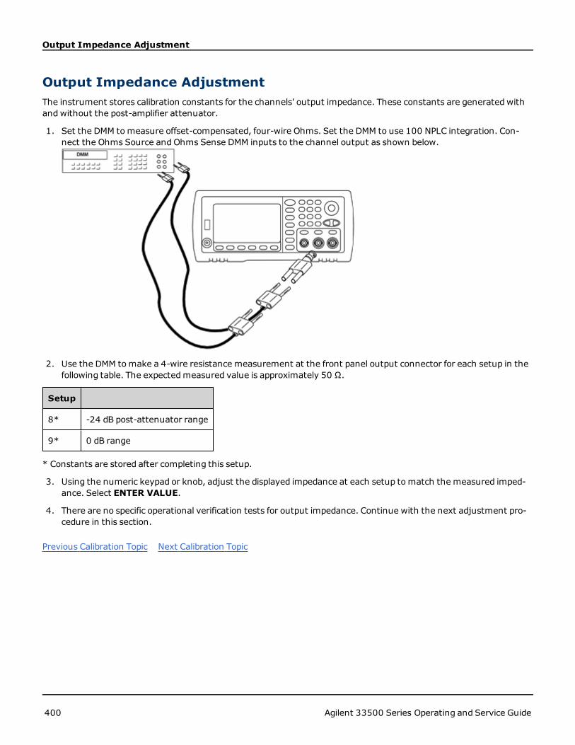
Output Impedance Adjustment
Output Impedance AdjustmentThe instrument stores calibration constants for the channels' output impedance. These constants are generated withandwithout the post-amplifier attenuator.
1. Set the DMM tomeasure offset-compensated, four-wire Ohms. Set the DMM to use 100 NPLC integration. Con-nect the Ohms Source and Ohms Sense DMM inputs to the channel output as shown below.
2. Use the DMM tomake a 4-wire resistance measurement at the front panel output connector for each setup in thefollowing table. The expectedmeasured value is approximately 50 Ω.
Setup
8* -24 dB post-attenuator range
9* 0 dB range
* Constants are stored after completing this setup.
3. Using the numeric keypad or knob, adjust the displayed impedance at each setup tomatch the measured imped-ance. Select ENTER VALUE.
4. There are no specific operational verification tests for output impedance. Continue with the next adjustment pro-cedure in this section.
Previous Calibration Topic Next Calibration Topic
400 Agilent 33500 Series Operating and Service Guide

AC Amplitude (high-impedance) Adjustment
AC Amplitude (high-impedance) AdjustmentThe instrument stores a calibration constant for each high-impedance attenuator path. Each path's gain coefficient iscalculated using twomeasurements: one with the waveform DAC at + output and one with waveform DAC at – out-put. The setups, therefore, must be performed in pairs.
1. Connect the DMM to the channel output as shown below.
2. Use the DMM tomeasure the DC voltage at the front-panel connector for each setup in the following table.
Setup Nominal Signal
DC Level
10 +0.0028 V Output of -72 dB range
11* - 0.0028 V Output of -72 dB range
12 +0.007 V Output of -64 dB range
13* -0.007 V Output of -64 dB range
14 +0.017 V Output of -56 dB range
15* -0.017 V Output of -56 dB range
16 +0.044 V Output of -48 dB range
17* -0.044 V Output of -48 dB range
18 +0.11 V Output of -40 dB range
19* -0.11 V Output of -40 dB range
20 +0.28 V Output of -32 dB range
21* -0.28 V Output of -32 dB range
22 +0.68 V Output of -24 dB range
23* -0.68 V Output of -24 dB range
24 +1.7 V Output of -16 dB range
Agilent 33500 Series Operating and Service Guide 401

AC Amplitude (high-impedance) Adjustment
Setup Nominal Signal
DC Level
25* -1.7 V Output of -16 dB range
26 +4.3 V Output of -8 dB range
27* -4.3 V Output of -8 dB range
28 +10.8 V Output of 0 dB range
29* -10.8 V Output of 0 dB range
30 +0.044V Output of -48 dB High DC range
31* -0.044V Output of -48 dB High DC range
32 +0.11 V Output of -40 dB High DC range
33* -0.11 V Output of -40 dB High DC range
34 +0.28 V Output of -32 dB High DC range
35* -0.28 V Output of -32 dB High DC range
36 +0.68 V Output of -24 dB High DC range
37* -0.68 V Output of -24 dB High DC range
* Constants are stored after completing this setup.
3. Using the numeric keypad or knob, adjust the displayed voltage at each setup tomatch the measured voltage.Select ENTER VALUE.
4. After performing setup 37:
a. If your calibration procedures require you to verify this adjustment, exit the calibration menu and perform ACAmplitude (high-impedance) Verification.
b. If you are making all of the adjustments and then verifying the instrument’s performance, continue with thenext procedure in this section.
Previous Calibration Topic Next Calibration Topic
402 Agilent 33500 Series Operating and Service Guide

-24 dB Range Flatness Adjustment
-24 dB Range Flatness Adjustment1. Connect a precision AC voltmeter to measure the output amplitude as shown below. Connect the BNC cable to the
Wide Band input of the Fluke 5790A.
2. Use the precision AC voltmeter to measure the output amplitude for each setup in the table below.
Setup Nominal Signal
Frequency Amplitude
38* 1 kHz 0.192 Vrms Flatness for -24 dB range
39* 100 kHz 0.192 Vrms Flatness for -24 dB range
40* 1 MHz 0.192 Vrms Flatness for -24 dB range
41* 5 MHz 0.192 Vrms Flatness for -24 dB range
42* 10 MHz 0.192 Vrms Flatness for -24 dB range
43* 20 MHz 0.192 Vrms Flatness for -24 dB range
44* 25 MHz 0.192 Vrms Flatness for -24 dB range
45* 30 MHz 0.192 Vrms Flatness for -24 dB range
* Constants are stored after completing this setup.
3. Using the numeric keypad or knob, adjust the displayed voltage at each setup tomatch the measured voltage.Select ENTER VALUE.
4. After performing setup 45:
a. If your calibration procedures require you to verify the adjustment just made, exit the calibration menu andperform -24 dB Range Flatness Verification.
b. If you are making all of the adjustments and then verifying the instrument’s performance, continue with thenext procedure in this section.
Previous Calibration Topic Next Calibration Topic
Agilent 33500 Series Operating and Service Guide 403

-8 dB Range Flatness Adjustment
-8 dB Range Flatness Adjustment1. Connect a precision AC voltmeter to measure the output amplitude as shown below. Connect the BNC cable to the
Wide Band input of the Fluke 5790A.
2. Use the precision AC voltmeter to measure the output amplitude for each setup in the table below.
Setup Nominal Signal
Frequency Amplitude
46* 1 kHz 1.22 Vrms Flatness for -8 dB range
47* 100 kHz 1.22 Vrms Flatness for -8 dB range
48* 1 MHz 1.22 Vrms Flatness for -8 dB range
49* 5 MHz 1.22 Vrms Flatness for -8 dB range
50* 10 MHz 1.22 Vrms Flatness for -8 dB range
51* 20 MHz 1.22 Vrms Flatness for -8 dB range
52* 25 MHz 1.22 Vrms Flatness for -8 dB range
53* 30 MHz 1.22 Vrms Flatness for -8 dB range
* Constants are stored after completing this setup.
3. Using the numeric keypad or knob, adjust the displayed voltage at each setup tomatch the measured voltage.Select ENTER VALUE.
4. After performing setup 53:
a. If your calibration procedures require you to verify the adjustment just made, exit the calibration menu andperform -8 dB Range Flatness Verification.
b. If you are making all the adjustments and then verifying the instrument’s performance, verify the output spec-ifications of the instrument with the Performance Verification Tests.
This completes the adjustment procedures for the one-channel instrument. Verification of the output specifications isrecommended.
404 Agilent 33500 Series Operating and Service Guide

-8 dB Range Flatness Adjustment
If you are making adjustments to a two-channel instrument, continue with the next procedure in this section.
Previous Calibration Topic Next Calibration Topic
Agilent 33500 Series Operating and Service Guide 405

Channel 2 Adjustments
Channel 2 AdjustmentsThe following topics describe calibration adjustments on channel 2.
l Self Calibration Adjustment (Channel 2)
l Output Impedance Adjustment (Channel 2)
l AC Amplitude (high-impedance) Adjustment (Channel 2)
l -24 dB Range Flatness Adjustment (Channel 2)
l -8 dB Range Flatness Adjustment (Channel 2)
Previous Calibration Topic Next Calibration Topic
406 Agilent 33500 Series Operating and Service Guide

Self Calibration Adjustment (Channel 2)
Self Calibration Adjustment (Channel 2)1. Enter and begin the following setup.
Setup
54* Self-calibration. The output is disabled.
* Constants are stored after completing this setup.
2. After performing setup 54:
a. If your calibration procedures require you to verify the adjustment just made, exit the calibration menu andperform DCOffset Voltage Verification. Be sure to do this for channel 2.
b. If you are making all of the adjustments and then verifying the instrument’s performance, continue with thenext procedure in this section.
This setup requires approximately 15 seconds to complete.
Previous Calibration Topic Next Calibration Topic
Agilent 33500 Series Operating and Service Guide 407

Output Impedance Adjustment (Channel 2)
Output Impedance Adjustment (Channel 2)The instrument stores calibration constants for the channels' output impedance. These constants are generated withandwithout the post-amplifier attenuator.
1. Set the DMM tomeasure offset-compensated, four-wire Ohms. Set the DMM to use 100 NPLC integration. Con-nect the Ohms Source and Ohms Sense DMM inputs to the channel output as shown below.
2. Use the DMM tomake a 4-wire resistance measurement at the front panel output connector for each setup in thefollowing table. The expectedmeasured value is approximately 50 Ω.
Setup
55* -24 dB post-attenuator range
56* 0 dB range
* Constants are stored after completing this setup.
3. Using the numeric keypad or knob, adjust the displayed impedance at each setup tomatch the measured imped-ance. Select ENTER VALUE.
4. There are no specific operational verification tests for output impedance. Continue with the next adjustment pro-cedure in this section.
Previous Calibration Topic Next Calibration Topic
408 Agilent 33500 Series Operating and Service Guide

AC Amplitude (high-impedance) Adjustment (Channel 2)
AC Amplitude (high-impedance) Adjustment (Channel 2)The instrument stores a calibration constant for each high-impedance attenuator path. Each path's gain coefficient iscalculated using twomeasurements: one with the waveform DAC at + output and one with waveform DAC at – out-put. The setups, therefore, must be performed in pairs.
1. Connect the DMM to the channel output as shown below.
2. Use the DMM tomeasure the DC voltage at the front-panel connector for each setup in the following table.
Nominal Signal
Setup DC Level
57 +0.0028 V Output of -72 dB range
58* - 0.0028 V Output of -72 dB range
59 +0.007 V Output of -64 dB range
60* -0.007 V Output of -64 dB range
61 +0.017 V Output of -56 dB range
62* -0.017 V Output of -56 dB range
63 +0.044 V Output of -48 dB range
64* -0.044 V Output of -48 dB range
65 +0.11 V Output of -40 dB range
66* -0.11 V Output of -40 dB range
67 +0.28 V Output of -32 dB range
68* -0.28 V Output of -32 dB range
69 +0.68 V Output of -24 dB range
Agilent 33500 Series Operating and Service Guide 409

AC Amplitude (high-impedance) Adjustment (Channel 2)
Nominal Signal
Setup DC Level
70* -0.68 V Output of -24 dB range
71 +1.7 V Output of -16 dB range
72* -1.7 V Output of -16 dB range
73 +4.3 V Output of -8 dB range
74* -4.3 V Output of -8 dB range
75 +10.8 V Output of 0 dB range
76* -10.8 V Output of 0 dB range
77 +0.044V Output of -48 dB High DC range
78* -0.044V Output of -48 dB High DC range
79 +0.11 V Output of -40 dB High DC range
80* -0.11 V Output of -40 dB High DC range
81 +0.28 V Output of -32 dB High DC range
82* -0.28 V Output of -32 dB High DC range
83 +0.68 V Output of -24 dB High DC range
84* -0.68 V Output of -24 dB High DC range
* Constants are stored after completing this setup.
3. Using the numeric keypad or knob, adjust the displayed voltage at each setup tomatch the measured voltage.Select ENTER VALUE.
4. After performing setup 84:
a. If your calibration procedures require you to verify this adjustment, exit the calibration menu and perform ACAmplitude (high-impedance) Verification.
b. If you are making all of the adjustments and then verifying the instrument’s performance, continue with thenext procedure in this section.
Previous Calibration Topic Next Calibration Topic
410 Agilent 33500 Series Operating and Service Guide

-24 dB Range Flatness Adjustment (Channel 2)
-24 dB Range Flatness Adjustment (Channel 2)1. Connect a precision AC voltmeter to measure the output amplitude as shown below. Connect the BNC cable to the
Wide Band input of the Fluke 5790A.
2. Use the precision AC voltmeter to measure the output amplitude for each setup in the table below.
Setup Nominal Signal
Frequency Amplitude
85* 1 kHz 0.192 Vrms Flatness for -24 dB range
86* 100 kHz 0.192 Vrms Flatness for -24 dB range
87* 1 MHz 0.192 Vrms Flatness for -24 dB range
88* 5 MHz 0.192 Vrms Flatness for -24 dB range
89* 10 MHz 0.192 Vrms Flatness for -24 dB range
90* 20 MHz 0.192 Vrms Flatness for -24 dB range
91* 25 MHz 0.192 Vrms Flatness for -24 dB range
92* 30 MHz 0.192 Vrms Flatness for -24 dB range
* Constants are stored after completing this setup.
3. Using the numeric keypad or knob, adjust the displayed voltage at each setup tomatch the measured voltage.Select ENTER VALUE.
4. After performing setup 92:
a. If your calibration procedures require you to verify the adjustment just made, exit the calibration menu andperform -24 dB Range Flatness Verification. Be sure that you do this for Channel 2.
b. If you are making all of the adjustments and then verifying the instrument’s performance, continue with thenext procedure in this section.
Previous Calibration Topic Next Calibration Topic
Agilent 33500 Series Operating and Service Guide 411

-8 dB Range Flatness Adjustment (Channel 2)
-8 dB Range Flatness Adjustment (Channel 2)This section applies to channel 2. It checks high frequency AC amplitude flatness on the -8 dB attenuator range. It alsochecks flatness for all other ranges excluding the -24 dB and 0 dB attenuator ranges.
1. Connect a precision AC voltmeter to measure the output amplitude as shown below. Connect the BNC cable to theWide Band input of the Fluke 5790A.
2. Use the precision AC voltmeter to measure the output amplitude for each setup in the table below.
Nominal Signal
Setup Frequency Amplitude
93* 1 kHz 1.22 Vrms Flatness for -8 dB range
94* 100 kHz 1.22 Vrms Flatness for -8 dB range
95* 1 MHz 1.22 Vrms Flatness for -8 dB range
96* 5 MHz 1.22 Vrms Flatness for -8 dB range
97* 10 MHz 1.22 Vrms Flatness for -8 dB range
98* 20 MHz 1.22 Vrms Flatness for -8 dB range
99* 25 MHz 1.22 Vrms Flatness for -8 dB range
100* 30 MHz 1.22 Vrms Flatness for -8 dB range
* Constants are stored after completing this setup.
3. Using the numeric keypad or knob, adjust the displayed voltage at each setup tomatch the measured voltage.Select ENTER VALUE.
4. After performing setup 100, you have now completed the recommended adjustment procedures. Verification ofthe output specifications is recommended.
a. If your calibration procedures require you to verify the adjustment just made, exit the calibration menu andperform -8 dB Range Flatness Verification.
Previous Calibration Topic Next Calibration Topic
412 Agilent 33500 Series Operating and Service Guide

Calibration Errors
Calibration ErrorsThe following errors may occur during calibration. There are also system errors and self-test errors. Some error mes-sages include a failing channel number (1 or 2), shown as n in the messages below.
701 Calibration error; security defeated by hardware jumper
If you short the calibration secure jumper (CAL ENABLE) while turning the instrument on, this error indicates the secu-rity password has been overwritten. See Calibration Security for details.
702 Calibration error; calibration memory is secured
To perform calibration, unsecure the instrument. See Secure and Unsecure Instrument for Calibration for details.
703 Calibration error; secure code provided was invalid
Specified security code was invalid.
706 Calibration error; value out of range
Value entered was outside valid range.
707 Calibration error; signal input is out of range
Occurs during the ADC Adjustment, setup 6, if the 1 V input voltage is too high. May also occur during self-calibration(setup 7). Run self-test to diagnose problem.
710 Self-calibration failed; Chan n, null DAC cal, invalid self calSelf-calibration failed; Chan n, offset DAC cal with attenuator, invalid self calSelf-calibration failed; Chan n, offset DAC cal no attenuator, invalid self cal
Error occurred while performing internal calibration of specified DAC. Self-calibration exited without changing self-cal-ibration constants. Run self-test to diagnose problem.
711 Self-calibration failed; Chan n, null DAC cal gain too low (too high), <meas_value>Self-calibration failed; Chan n, offset DAC cal with attenuator gain too low (too high), <meas_value>Self-calibration failed; Chan n, offset DAC cal no attenuator gain too low (too high), <meas_value>
Computed gain calibration factor for specified DACwas out of limits. Self-calibration exited without changing self-cal-ibration constants. Run self-test to diagnose problem.
Agilent 33500 Series Operating and Service Guide 413

Calibration Errors
712 Self-calibration failed; Chan n, null DAC cal zero too low (too high), <meas_value>Self-calibration failed; Chan n, offset DAC cal with attenuator zero too low (too high), <meas_value>Self-calibration failed; Chan n, offset DAC cal no attenuator zero too low (too high), <meas_value>Self-calibration failed; Chan n, GND measurement out of limits, <meas_value>
Computed zero calibration factor for specified DACwas out of limits. Self-calibration exited without changing self-cal-ibration constants. Run self-test to diagnose problem.
715 Self-calibration failed; Chan n, null DAC cal, convergence error sub attenuator value dB
Internal null DAC calibration failed to converge during internal calibration. Self-calibration exited without changing self-calibration constants. Run self-test to diagnose problem.
720 Self-calibration failed; Chan n, offset DAC cal with attenuator, convergence errorSelf-calibration failed; Chan n, offset DAC cal no attenuator, convergence error
Internal offset DAC calibration failed to converge internal calibration. Self-calibration exited without changing self-cal-ibration constants. Run self-test to diagnose problem.
850 Calibration error; set up is invalid
Invalid calibration setup number selected.
850 Calibration error; set up is out of order
Certain calibration steps require a specific beginning and ending. Do not enter into middle of a calibration sequence.
Previous Calibration Topic
414 Agilent 33500 Series Operating and Service Guide

Block Diagram
Block DiagramThe instrument has four main assemblies:
l Processor
l Main board
l Front panel
l Main power supply
A simplified block diagram appears at the bottom of this section.
The processor is a single board computer that contains the CPU, RAM, ROM, and circuits used to drive the GPIB, LAN,and USB ports. The built in web interface is contained in the ROM. The processor circuitry is earth referenced.
When the power switch is pressed, the processor communicates with and loads the FPGA. This communication usesthree asynchronous serial data lines and one serial clock line. These four lines are isolated.
The FPGA stores all waveforms except arbitrary waveforms. Arbitrary waveforms are loaded into SDRAM on the mainboard. All control of waveforms, triggers, sync signals, output path, attenuation, and offset is provided by the FPGA.
The main waveform for each channel (only one channel is shown in the block diagram) is loaded into the waveformDAC and clocked by the timebase. The DAC output passes through an elliptical filter before the main attenuators. Thereare three attenuators available in the path, -7.96 dB, -15.91 dB, and -23.87 dB.
The signal is applied to the output amplifier. The DC offset is summed at the output amplifier. A post amplifier -23.87 dBattenuator is available for low level signals. The table below show the attenuators that create the output signal ampli-tude.
Output RangeDC Offset < 320 mV
-7.96 dB -15.91 dB -23.87 dB -23.87 dB(post)
10 Vpp - 3.6 Vpp Out Out Out Out
4 Vpp - 1.44 Vpp In Out Out Out
1.6 Vpp - 576 mVpp Out In Out Out
640 mVpp - 230 mVpp Out Out Out In
256 mVpp - 92 mVpp In Out Out In
102.4 mVpp - 36.86 mVpp Out In Out In
40.96 mVpp - 14.75 mVpp Out Out In In
16.38 mVpp - 5.90 mVpp In Out In In
6.55 mVpp - 2.36 mVpp Out In In In
2.62 mVpp - 1.00 mVpp In In In In
Output RangeDCOffset ≥ 320 mV
-7.96 dB -15.91 dB -23.87 dB -23.87 dB(post)
9.36 Vpp - 3.6 Vpp Out Out Out Out
Agilent 33500 Series Operating and Service Guide 415

Block Diagram
Output RangeDC Offset < 320 mV
-7.96 dB -15.91 dB -23.87 dB -23.87 dB(post)
4 Vpp - 1.44 Vpp In Out Out Out
1.6 Vpp - 576 mVpp Out In Out Out
640 mVpp - 230 mVpp Out Out In Out
256 mVpp - 92 mVpp In Out In Out
102.4 mVpp - 36.86 mVpp Out In In Out
40.96 mVpp - 1.00 mVpp In In In Out
The output relay when enabled provides the waveform to the front panel BNC connector. Additionally, this relay, whendisabled, routes the signal to the Modulation ADC for internal self-test and calibration routines.
The output relay is controlled by the FPGA. Two circuits provide overvoltage and over current protection, primarily froman external circuit. The instrument can source very low output impedances.
The Sync output signal is generated as a waveform from the FPGA to the Sync DAC.
External trigger in and out is chassis referenced at the BNC connector but is isolated before the FPGA.
Modulation in is an isolated input to the A/D converter. The FPGA applies the modulation signal to the output wave-form.
The instrument's clock generator employs a 10-MHz crystal oscillator and a phase-locked loop to generate the 250-MHzclocks used by the FPGA andWaveform DACs.When an external 10-MHz frequency reference is used, a digital phase-locked loop in the FPGA keeps the crystal oscillator in sync.
416 Agilent 33500 Series Operating and Service Guide

Block Diagram
Block Diagram
Agilent 33500 Series Operating and Service Guide 417
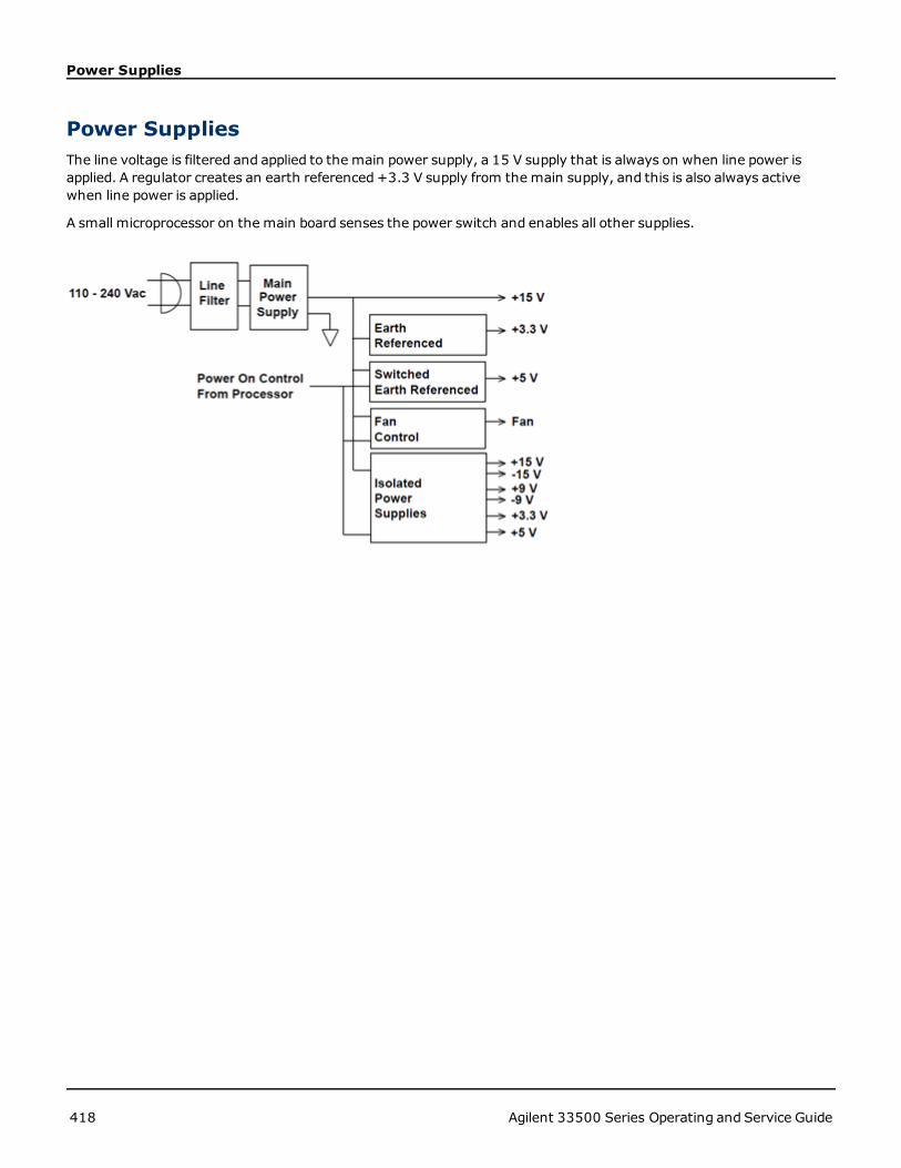
Power Supplies
Power SuppliesThe line voltage is filtered and applied to the main power supply, a 15 V supply that is always on when line power isapplied. A regulator creates an earth referenced+3.3 V supply from the main supply, and this is also always activewhen line power is applied.
A small microprocessor on the main board senses the power switch and enables all other supplies.
418 Agilent 33500 Series Operating and Service Guide

Troubleshooting
TroubleshootingA brief list of common failures appears below. Before troubleshooting or repairing the instrument, make sure the failureis in the instrument rather than any external connections. Also make sure that the instrument was accurately cal-ibrated within the last year (see Calibration Interval). The instrument’s circuits allow troubleshooting and repair withbasic test equipment.
Unit is Inoperative
Verify that:
l the AC power cord is securely connected to the instrument and plugged into a live outlet
l the front-panel Power On/Standby switch has been pushed
Unit Fails Self-Test
Ensure that all connections (front and rear) are removedwhen self-test is performed. During self-test, errors may beinduced by signals present on external wiring, such as long test leads that can act as antennas.
DONOT swap the motherboard, the processor board, or the front panel board from one instru-ment to another. These boards contain model number and serial number information thatuniquely identifies a specific unit, and boards that are mismatched to the instrument may resultin problems with its performance, licensing, serviceability, importability/exportability or war-ranty.
Power Supplies
Verify the main power supply.
Shock Hazard. To check the power supplies, remove the instrument cover as described in Dis-assembly.
The main power supply provides a +15 VDC (±0.3 VDC) supply to the main circuit board. All other supplies are derivedfrom this supply. This supply is energized at all times while the line power cord is connected.
Test the supply at the connector to the main board. Note that the supply is not referenced to the chassis when dis-connected from the main board.
l Circuit failure can cause heavy supply loads which may pull down the supply output voltage. Disconnect the mainsupply from the main board to test.
l Always check the supply is free of oscillations using an oscilloscope.
l The main power supply contains a fuse. Replacing this fuse is not recommended. Replace the entire main powersupply assembly. Note that power supply failures are often caused by other instrument failures.
The heat sinks on the main board are at different potentials. Damagemay occur if any of theheat sinks are shorted together. Use care when probing the main board.
Verify the power supplies listed in the table below and shown in the figure on page 146. Earth referenced supplies maybe tested using the chassis as ground. Isolated suppliedmay be tested by using one of the heat sinks shown in the fig-ure.
Agilent 33500 Series Operating and Service Guide 419

Troubleshooting
Supply
+3.3 V ER*
+5 ER
+15 V Isolated
-15 V Isolated
+9 V Isolated
-9 V Isolated
+3.3 V Isolated
+5 V Isolated
* This supply is active whenever AC power is applied to the instrument.
Self-Test Errors 605 - 609
Self-test errors 605-609 indicate that the processor board is unable to correctly program or communicate with thewaveform FPGA (U1005) on the main board. In this case, further troubleshooting is required. The problem could be dueto out of date firmware, or a failing or unseated processor board or main board. Before troubleshooting these errors,ensure that the instrument firmware is up to date. If the errors are still being reported, continue with the following pro-cedure.
420 Agilent 33500 Series Operating and Service Guide

Troubleshooting
Reseat the Boards
Power off the unit, remove the cover. Reseat the processor board and the main board. Power up the unit and see if theerrors 605-609 are still reported at power-on.
Check Power Supplies
Probe the system power supplies and verify they are operating within limits. If any of the power supplies are out oflimit, diagnose the power supply. Otherwise, continue on to check SPI communications.
Check SPI Communications
If you still see errors after reseating the boards, the next step is to probe the SPI communications lines between theprocessor board and the main board. First, locate LED DS1001 on the main board as shown below. Cycle power on theunit, wait until it fully boots, and see whether the main board LED illuminates. The main board LED indicates whetherthe FPGA was successfully programmed. The following sections indicate which signal lines to probe on the main boardconnector (J201).
Main Board LED Lights up after Boot
This indicates that the FPGA is programmed and running. Most likely there is a communications failure from the mainboard to the processor board. Probe the J201, pin 27 line with an oscilloscope, and cycle power on the unit (wait for fullboot) to see if there is activity on the line. Activity should be +3.3 V pulses (isolated). Note that activity ceases once theinstrument is booted.
Agilent 33500 Series Operating and Service Guide 421

Troubleshooting
l If there is no activity on the line even after the LED lights up, then most likely the main board is the cause of thefailure.
l If there is activity on the line, then the processor board is the most likely cause of the failure.
Main Board LED Does not Light up after Boot
This indicates that the processor was unable to program the FPGA. Most likely there is a communications failure fromthe processor board to the main board. Probe the following serial data lines at power upwith an oscilloscope:
l J201, pin 23
l J201, pin 24
l J201, pin 26
l J201, pin 32
If all of the above SPI lines show activity during FPGA programming, then the main board is the most likely cause of thefailure. Otherwise, the processor board is the most likely cause.
10 MHz Out
If the power supplies are functional and self-test passes, check the 10 MHz output at the rear panel. This output ispresent whenever the instrument has powered on and the processor andmain board are operational. If the 10 MHz ispresent, but the display is not working, suspect the front panel board or display assembly.
422 Agilent 33500 Series Operating and Service Guide

Self-Test Procedures
Self-Test Procedures
Power-On Self-Test
Each time the instrument is powered on, a subset of self-tests are performed. These tests check that the minimum setof logic and subsystems are functioning properly.
Full Self-Test
Passing self-test provides a high degree of confidence that instrument is operating normally. Self-test procedure sys-tematically exercises internal oscillator, digital infrastructure, waveform memory, and analog attenuator paths. Itattempts to isolate failures to a particular assembly to facilitate service. During the test, instrument main output(s) aredisconnected internally from the BNC connectors and are connected to the internal ADC, which checks for expected sig-nal levels throughout the instrument.
A complete self-test (*TST?) takes approximately 15 seconds. You may hear relays switching during the procedure.When self-test completes, either "Self-test Passed" or "Self-test Failed" appears on front panel. Self-test error mes-sages are described in detail below.
Execute self-test before any verifications or adjustments.
To Run Self-Test
Remove all input connections to instrument before self-test. Cycle power to run power-on self-test.
Remote I/O Execution
1. Connect to instrument using remote interface (LAN Configuration Procedure).
2. Send *TST? and read the result: Pass (+0) or fail (+1). Use SYSTem:ERRor? to view errors.
Front Panel Execution
1. Press [System] > Instr Setup > Self Test.
2. A progress bar will appear as self-test executes. After completion, view any failures by pressing [System] > Helpand then choosing the topic View remote command error queue.
Self-Test Error Numbers and Messages
A failure can generate multiple error messages; the first one should be considered the primary cause of failure. Someerror messages include a failing channel number (1 or 2), shown as n in the messages below.
Agilent 33500 Series Operating and Service Guide 423
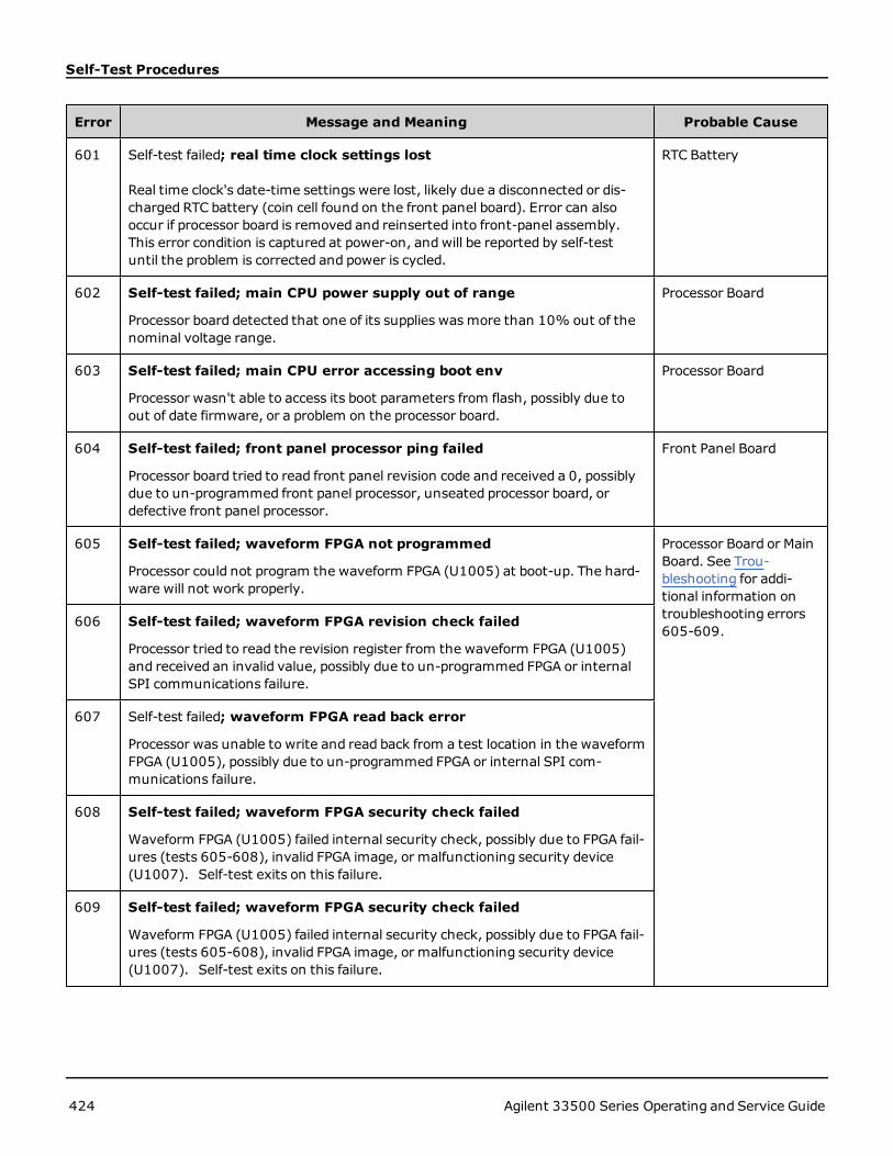
Self-Test Procedures
Error Message and Meaning Probable Cause
601 Self-test failed; real time clock settings lost
Real time clock's date-time settings were lost, likely due a disconnected or dis-charged RTC battery (coin cell found on the front panel board). Error can alsooccur if processor board is removed and reinserted into front-panel assembly.This error condition is captured at power-on, andwill be reported by self-testuntil the problem is corrected and power is cycled.
RTC Battery
602 Self-test failed; main CPU power supply out of range
Processor board detected that one of its supplies wasmore than 10% out of thenominal voltage range.
Processor Board
603 Self-test failed; main CPU error accessing boot env
Processor wasn't able to access its boot parameters from flash, possibly due toout of date firmware, or a problem on the processor board.
Processor Board
604 Self-test failed; front panel processor ping failed
Processor board tried to read front panel revision code and received a 0, possiblydue to un-programmed front panel processor, unseated processor board, ordefective front panel processor.
Front Panel Board
605 Self-test failed; waveform FPGA not programmed
Processor could not program the waveform FPGA (U1005) at boot-up. The hard-ware will not work properly.
Processor Board or MainBoard. See Trou-bleshooting for addi-tional information ontroubleshooting errors605-609.
606 Self-test failed; waveform FPGA revision check failed
Processor tried to read the revision register from the waveform FPGA (U1005)and received an invalid value, possibly due to un-programmed FPGA or internalSPI communications failure.
607 Self-test failed; waveform FPGA read back error
Processor was unable to write and read back from a test location in the waveformFPGA (U1005), possibly due to un-programmed FPGA or internal SPI com-munications failure.
608 Self-test failed; waveform FPGA security check failed
Waveform FPGA (U1005) failed internal security check, possibly due to FPGA fail-ures (tests 605-608), invalid FPGA image, or malfunctioning security device(U1007). Self-test exits on this failure.
609 Self-test failed; waveform FPGA security check failed
Waveform FPGA (U1005) failed internal security check, possibly due to FPGA fail-ures (tests 605-608), invalid FPGA image, or malfunctioning security device(U1007). Self-test exits on this failure.
424 Agilent 33500 Series Operating and Service Guide

Self-Test Procedures
Error Message and Meaning Probable Cause
610 Self-test failed; main PLL not locked
Waveform FPGA (U1005) unable to lock to internal 10MHz oscillator (U903 orU905).
Main Board
611 Self-test failed; FPGA PLL not locked
Waveform FPGA (U1005) unable to lock to internal sample clock generator IC(U906).
Main Board
612 Self-test failed; Chan n, waveform memory PLL not locked
Waveform RAM for indicated channel (U1101 or U1102) was unable to lock to itsclock.
Main Board
613 Self-test failed; Chan n, waveform memory not initialized
Waveform RAM for indicated channel (U1101 or U1102) failed to initialize.
Main Board
615 Self-test failed; modulation ADC offset too low (too high)
Internal ADC's measurement of ACOM out of limits.
Main Board
616 Self-test failed; modulation ADC reference too low (too high)
Internal ADC's measurement of its voltage reference (VRef) was out of limits.
Main Board
620 Self-test failed; Chan n, waveform memory test failed on idle
Waveform memory test not started properly, probably due to error in waveformFPGA (U1005)
Main Board
621 Self-test failed; Chan n, waveform memory test failed
Waveform RAMmemory test for the indicated channel (U1101 or U1102) failed;test consists of writing and reading back the entire waveform RAM with a prede-termined pattern.
Main Board
625 Self-test failed; Chan n, waveform DAC gain[idx] too low (too high)
Waveform DAC (U1801 or U1501) not providing correct output. Gain [idx] of 1references POS voltage test; gain [idx] of 2 references NEG voltage test.
Main Board
630 Self-test failed; Chan n, sub attenuator failure 0dB
Trim DAC inside waveform DAC (U1801 or U1501) not providing correct outputat 0 dB. If this fails, test 631 will not be executed.
Main Board
631 Self-test failed; Chan n, sub attenuator <-7.00 to 0.00>dB too low(too high)
Trim DAC inside waveform DAC (U1801 or U1501) producing output outsideexpected range.
Main Board
Agilent 33500 Series Operating and Service Guide 425

Self-Test Procedures
Error Message and Meaning Probable Cause
635 Self-test failed; Chan n, null DAC gain[idx] too low (too high)
Aux DAC output of waveform DAC (U1801 or U1501) or its associated analog cir-cuitry producing output outside expected range. Gain [idx] of 1 references POSvoltage test; gain [idx] of 2 references NEG voltage test.
Main Board
640 Self-test failed; Chan n, offset DAC gain[idx] too low (too high)
Offset DAC (U1702 or U2002) or its associated circuitry producing output out-side expected range. For offset DAC, [idx] polarities are inverted: gain [idx] of 1references NEG voltage test; gain [idx] of 2 references POS voltage test.
Main Board
650 Self-test failed; Chan n, 0dB path failure expected 0dB, measured valuedB
Straight-through path (no attenuator) from waveform DAC to ADC input pro-ducing output outside expected range. If this fails, extended attenuator test 655is not executed.
Main Board
655 Self-test failed; Chan n, -8 dB pre attenuator path too low (too high)Self-test failed; Chan n, -16 dB pre attenuator path too low (too high)Self-test failed; Chan n, -24 dB pre attenuator path too low (too high)Self-test failed; Chan n, -24 dB post attenuator path too low (too high)
Specified attenuator relay malfunctioning, or associated circuitry not providingexpected attenuation.
Main Board
426 Agilent 33500 Series Operating and Service Guide

Replaceable Parts
Replaceable PartsAlways use anti-static techniques when assemblies are handled or serviced.
The following table lists the replacement assemblies for the instrument:
Part Number Description
34401-86020 Bumper Kit
34401-45021 Handle
33220-84101 Cover
1990-3263 Encoder
35220-87401 Knob
33521-80001 Keypad for one-channel models
33522-80001 Keypad for two-channel models
2090-0977 Display
1250-3569 Front Panel BNCs
33521-80002 Front Panel for 33521A
33522-80002 Front Panel for 33522A
33520-80001 Front Panel for 335xxB one-channel models
33520-80002 Front Panel for 335xxB two-channel models
33522-66502 Front Panel Board
1252-8483 USB Connector
1253-4669 LAN Connector
53200-61608 Line Filter
33250-68501 Fan
1420-0356 Battery (in Front Panel) CR2032
53200-80002 Power Supply and Cover*
* The power supply contains a 15 A, 250 V radial lead fuse. Fuse replacement is not recommended.
Agilent 33500 Series Operating and Service Guide 427

Disassembly
DisassemblyThis section describes the procedure for disassembling the instrument.
Tools Required
The following tools are required for instrument disassembly.
l T15 Torx driver (most disassembly)
l T8 Torx driver (front panel disassembly)
l Posidriv and flat bladed screw drivers
l 14 mm nut driver, hollow shaft (rear-panel BNC connectors)
l 7 mm nut driver (rear-panel GPIB connector)
Only qualified, service-trained personnel who are aware of the hazards involved should removeinstrument covers. Always disconnect the power cable and any external circuits before removingthe instrument cover. Some circuits are active and have power applied even when the power switchis turned off.
General Disassembly Procedure
1. Turn off the power. Remove all cables from the instrument.
2. Rotate the handle upright and pull off.
3. Pull off the instrument bumpers.
428 Agilent 33500 Series Operating and Service Guide

Disassembly
4. Loosen the two captive screws (circled in red, below) in the rear bezel and remove the rear bezel.
5. Slide off the instrument cover.
Many of the service procedures can now be performedwithout further disassembly. Troubleshooting and service pro-cedures that require power be applied can be performedwith the instrument in this state of disassembly.
SHOCK HAZARD. Only service-trained personnel who are aware of the hazards involved shouldremove the instrument covers. Dangerous voltages may be encountered with the instrument cov-ers removed.
Main Component Disassembly
1. Remove processor board. Turn instrument over. Remove the T-8 screw securing the processor board. Press thetabs on the processor board connector and slide processor board toward the back of instrument to disengage theconnector. Lift processor board out.
Agilent 33500 Series Operating and Service Guide 429

Disassembly
2. Remove front panel assembly. Remove T15 screw holding the main board. Press latch on left side of front paneland latch in power supply cover on right side of front panel. Push sides of metal chassis toward center to disengagestuds on sides of front panel assembly. Gently pull front panel assembly straight off chassis. Note that front panelassembly has an electrical connector to the main board. Be careful not to damaged connector.
3. Remove Main Board. Disconnect power supply connector from main board. Disconnect GPIB andOscillator In rib-bon cables. Disconnect fan power cable from main board. Loosen and remove nuts securingModulation In andExt Trig BNC connector to rear panel. Remove screw below GPIB board securingmain board to chassis. Slide main
430 Agilent 33500 Series Operating and Service Guide
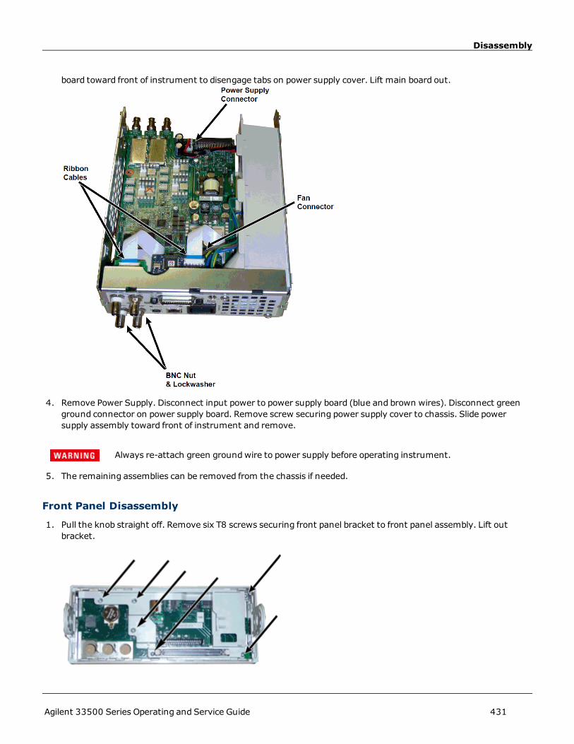
Disassembly
board toward front of instrument to disengage tabs on power supply cover. Lift main board out.
4. Remove Power Supply. Disconnect input power to power supply board (blue and brown wires). Disconnect greenground connector on power supply board. Remove screw securing power supply cover to chassis. Slide powersupply assembly toward front of instrument and remove.
Always re-attach green groundwire to power supply before operating instrument.
5. The remaining assemblies can be removed from the chassis if needed.
Front Panel Disassembly
1. Pull the knob straight off. Remove six T8 screws securing front panel bracket to front panel assembly. Lift outbracket.
Agilent 33500 Series Operating and Service Guide 431

Disassembly
2. Disconnect display ribbon cable from front panel board. Remove T8 screws securing front panel board to front panelassembly. Lift out printed circuit board.
3. All additional front panel assemblies can now be lifted out of front panel housing.
432 Agilent 33500 Series Operating and Service Guide