agilent 1260 infinity analytical sfc system installation instructions ... · analytical sfc system...
TRANSCRIPT

Agilent 1260 Infinity Analytical SFC System
Installation Instructions: Checkout Procedure
This technical note describes the checkout procedures for the Agilent 1260 Infinity Analytical SFC System.
Contents
Overview of the Checkout Procedure 2
SFC, SFC/MS Checklist 3
Open Lab CDS Configuration 5
Initial Setup – Solvents 5
Create SFC_CHECKOUT.M (from DEF_LC.M) 6
Monitoring of Pressure and Noise with Isocratic Flow 7
Sample Based Checkout - A Single Run 9
Reproducibility - Five Run Sequence 9
Mass Spectrometer Interface Checkout 11
Mass Spec Checkout Signal Settings 11APCI Sources– Spray Chamber Settings 12ESI Sources – Spray Chamber Settings 12Direct/Splitless Full Flow into Mass Spectrometer 13Split Flow into Mass Spectrometer 14
Hybrid Systems – UHPLC Checkout 15
Create UHPLC_Checkout.M 15Perform a Single Run 16Hybrid SFC/UHPLC MS 17
Agilent Technologies
Overview of the Checkout Procedure
Overview of the Checkout Procedure
2
While different configurations of the Agilent 1260 Infinity SFC systems are possible such as the SFC/UHPLC hybrid, instruments connected to mass spectrometers, or SFC systems which include additional detectors such as ELSD, and method development systems, all of the systems fundamentally contain the SFC control module (G4301A), SFC binary pump (G4302A) , standard autosampler (G4303A or modified G1329B), thermostatted column compartment (G1316C) and UV- detector (G1315C/D or G1365C/D). This fundamental core system (G4309A) will be specifically tested by the checkout and sample described below. Once this defined core system has been demonstrated to be operationally correct, other components can be added into the system or monitored for function. Again, we will start with the basics of a simple UV system (G4309A setup) and expand demonstrating the other complexities.
Requirements:
• Carbon dioxide
• Methanol 1 L (HPLC grade) modifier solvent, and injection wash solvent
• Water 1 L (deionized, HPLC grade) for hybrid SFC/HPLC systems
• Checkout column ( Zorbax Rx- Sil, 5 µm, 4.6 mm x 150 mm (883975- 901))
• SFC Checkout Sample (5190- 0584) transferred to a 2 mL HPLC vial
The checkout sample ( SFC Checkout Sample (5190- 0584)) contains four compounds dissolved in methanol. These compounds easily separate on the checkout column with methanol. Additionally, the sample separates on the same column in HPLC mode in a Hybrid system when used in conjunction with HPLC solvents (water/methanol). The checkout sample should be diluted 10:1, to demonstrate Agilent MS operation. If used undiluted, the sample may overload the MS source and may cause poorly shaped MS peaks.
Table 1 SFC Checkout Sample
Compound Nominal concentration
Expected masses
APCI + APCI - ESI - ESI +
Theophylline 250 µg/mL 181.1 179.1 179.1 181.1
Caffeine 250 µg/mL 195.1 -- -- 195.1
Thymine 250 µg/mL 127.1 125.1 125.1 127.1
Theobromine 250 µg/mL 181.1 -- -- 181.1
The checkout procedures described in this document represent a fundamental check of system operation and are not a substitute for IQ/OQ/PV. These operational checks quickly demonstrate the functioning of the various modules and devices that make up the system. However, rigorous performance monitoring and characterization is neither performed nor guaranteed by this checkout.
SFC, SFC/MS Checklist
SFC, SFC/MS Checklist
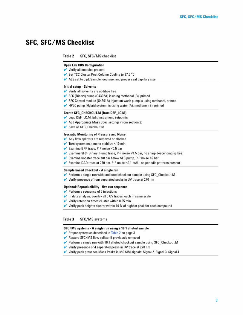
Table 2 SFC, SFC/MS checklist
Open Lab CDS Configuration✔ Verify all modules present✔ Set TCC Cluster Post Column Cooling to 37.5 °C✔ ALS set to 5 µL Sample loop size, and proper seat capillary size
Initial setup - Solvents✔ Verify all solvents are additive free✔ SFC (Binary) pump (G4302A) is using methanol (B), primed✔ SFC Control module (G4301A) Injection wash pump is using methanol, primed✔ HPLC pump (Hybrid system) is using water (A), methanol (B), primed
Create SFC_CHECKOUT.M (from DEF_LC.M)✔ Load DEF_LC.M, Edit Instrument Setpoints✔ Add Appropriate Mass Spec settings (from section 2)✔ Save as SFC_Checkout.M
Isocratic Monitoring of Pressure and Noise✔ Any flow splitters are removed or blocked✔ Turn system on, time to stabilize <10 min✔ Examine BPR trace, P-P noise <0.5 bar✔ Examine SFC (Binary) Pump trace, P-P noise <1.5 bar, no sharp descending spikes✔ Examine booster trace, ≈8 bar below SFC pump, P-P noise <2 bar✔ Examine DAD trace at 270 nm, P-P noise <0.1 mAU, no periodic patterns present
Sample based Checkout - A single run✔ Perform a single run with undiluted checkout sample using SFC_Checkout.M✔ Verify presence of four separated peaks in UV trace at 270 nm
Optional: Reproducibility - five run sequence✔ Perform a sequence of 5 injections✔ In data analysis, overlay all 5 UV traces, each in same scale✔ Verify retention times cluster within 0.05 min✔ Verify peak heights cluster within 10 % of highest peak for each compound
Table 3 SFC/MS systems
SFC/MS systems - A single run using a 10:1 diluted sample✔ Prepar system as described in Table 2 on page 3✔ Restore SFC/MS flow splitter if previously removed✔ Perform a single run with 10:1 diluted checkout sample using SFC_Checkout.M✔ Verify presence of 4 separated peaks in UV trace at 270 nm✔ Verify peak presence Mass Peaks in MS SIM signals: Signal 2, Signal 3, Signal 4
3

4
SFC, SFC/MS Checklist
Table 4 SFC/UHPLC Hybrid, Hybrid-MS systems - Additional Checklist Items
Create HPLC_Checkout.M✔ Prepare system as described in Table 2 on page 3✔ Load SFC_Checkout.M, Edit Instrument Settings✔ Add Appropriate Mass Spec settings (from section 2)✔ Save As UHPLC_Checkout.M
Perform a single run✔ Verify presence of 4 peaks in UV trace at 270 nm✔ For MS systems, verify peak presence in SIM signals: Signal 2, Signal 3, Signal 4
Open Lab CDS Configuration
Open Lab CDS Configuration
Before running the system, ensure that the system is properly configured and all modules are present and not in an error condition.
In complex or hybrid systems with multiple pumps, valves, or detectors, please see that each device has a descriptive ‘Device Name’ associated with each module. This can be performed with the Instrument menu’s Instrument Configuration selection. Labeling the SFC pump, HPLC pump, and Makeup pump by their respective functions will make understanding the method and system easier than Pump 1, Pump 2, or Pump 3.
In systems with a TCC Cluster and column switching, the left heat exchanger of the TCC containing the column outlet valve should be configured for Post Column Cooling. This temperature can only be set in Instrument Configuration. Please set the temperature of this Post Column Cooling zone to 37.5 °C. It should be noted that 37.5 °C is an initial recommendation for thermal matching to the UV detector. This value can be optimized for reduction in UV noise. This optimization is not part of this checkout procedure.
The SFC checkout method is based on a fixed loop autosampler (G4303A) with a 5 µL sample loop installed across the injection valve. Verify that the sampler contains a 5 µL loop and this and the appropriate seat capillary size are properly specified in the autosampler’s configuration. The green, 0.17 mm, seat capillary has a 2.3 µL volume.
Initial Setup – Solvents
The use of buffers or additives is not required for any of the solvents used in this checkout procedure and is specifically not recommended. Improper selection of additives may alter chromatography from the expected results or cause poor signals in a mass spectrometer or other detectors.
If using Solvent Selection with the SFC pump, set up methanol is its ‘B’ solvent. The SFC Control Module’s injection wash pump should utilize methanol as its wash solvent. In Hybrid configurations, the HPLC pump should be using water as solvent ‘A’ and methanol as solvent ‘B’.
Makeup pumps, if installed, are not required by this checkout. The addition of methanol as a makeup should not cause problems. However, the addition of buffers or additives should not be used. Demonstration of makeup pump operation should be performed after following the normal G4309 checkout.
5

Create SFC_CHECKOUT.M (from DEF_LC.M)
Create SFC_CHECKOUT.M (from DEF_LC.M)
6
• Load DEF_LC.M
• Modify the instrument settings, see Table 5 on page 6
• Save as SFC_CHECKOUT.M
Table 5 Instrument settings
SFC Pump (G4302A)
Advanced/Compressibility: Use Solvent Types checked
Flow Rate 2.500 mL/min
Composition 14 % B
Solvent types: A: CO2 (pre-compressed)B: MeOH (methanol)
SFC Control Module (G4301A)
SFC Mode checked
BPR Pressure 140.00 bar
BPR Temperature 60.00 °C
All other pumps [makeup, HPLC] should have a flow rate of 0.0 mL/min
Sampler (G4303A) configured for 5uL sample loop
Full Loop with overfill factor 3.0 (15 µL required sample volume)
Advanced/Draw Speed 75 µL/min
Advanced/Eject Speed 75 µL/min
Stop time 4 min
TCC / TCC Cluster
Post Column Cooling (Cluster), or Left Heat exchanger (TCC)
37.5 °C
Column position (if configured) Agilent Zorbax Rx-Sil checkout column
Column Temperature 40 °C
Diode Array (G1315C)
Use Signal A 270 nm, BW 4 , use Reference 360 nm, BW 100
Peakwidth > 0.025 min (0.5 s response time) (10 Hz)
Slit 8 nm
Valving (hybrid configurations)
Valving should be set to SFC operation (pumping and post BPR detection)
Mass Spectrometer (Agilent 6100 Series Single Quad with either APCI or Electrospray sources) - if present
Spray Chamber and signal parameters may be set up according to section 2.

Monitoring of Pressure and Noise with Isocratic Flow
Monitoring of Pressure and Noise with Isocratic Flow
It is recommended that any flow splitters be removed (or blocked) before beginning this test. The presence of a flow splitter in the system may obscure other characteristics and behaviors. Turn the system ON, allowing the system to come up and equilibrate. Ensure that the DAD has its front cover in place as this significantly affects noise.
The first operational check of a system is to setup a simple isocratic method and monitor pressure fluctuations and baseline noise. While an isocratic stream is flowing through the system, the operation of the pumping system, detector, and back pressure regulator can verified. This will be done by comparing peak- peak noise on the various pressure signals with expected values.
Set up the online signal plot adding the DAD1A, SFC pump pressure, Booster Pressure, and BPR Pressure signals. After the system becomes ready, the traces should appear as near flat lines. This may take up to 10 min after initially turning the system on. Some drift in the UV signal can be expected.
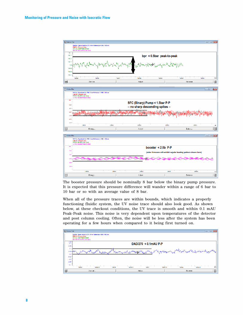
In the Online Plot window, select the appropriate signal and zoom in on a two minute window. Measure or estimate the peak- to- peak range of the pressure within these two minutes. Compare to the expected results below. The limits presented are general guidelines for a nominal system and not pass/fail criteria. The presence of flat traces without great wander, deviations, and spikes is the best indication of a properly functioning system.
7
8
Monitoring of Pressure and Noise with Isocratic Flow
The booster pressure should be nominally 8 bar below the binary pump pressure. It is expected that this pressure difference will wander within a range of 6 bar to 10 bar or so with an average value of 8 bar.
When all of the pressure traces are within bounds, which indicates a properly functioning fluidic system, the UV noise trace should also look good. As shown below, at these checkout conditions, the UV trace is smooth and within 0.1 mAU Peak- Peak noise. This noise is very dependent upon temperatures of the detector and post column cooling. Often, the noise will be less after the system has been operating for a few hours when compared to it being first turned on.
Sample Based Checkout - A Single Run
Most significantly, large, regular patterns should not appear in the UV trace. If very repeatable, periodic patterns do show up in the UV trace, an effort should be made to correlate the frequency of these patterns to one of the three pumps (Binary A (CO2), Binary B (methanol), booster pump), or the back pressure regulator. Periodic UV noise is generally derived from compositional errors in the SFC binary pump (check valves, seals, leaks, improper compressibility correction) or noise generated pressure perturbations caused by the BPR.
Random UV noise may be caused by improper setting or improper operation of post column heating/cooling.
Sample Based Checkout - A Single Run
As mentioned earlier, the SFC checkout sample contains four compounds that easily separate and elute on the Zorbax Rx- Sil checkout column. These peaks will all elute within 4 min. Injecting this sample and obtaining peaks gives a quick operational test of the injection system. Absence of the peaks is generally indicative of difficulties somewhere in the complete injection system.At this point, we are focusing on the UV signal only. While we may be collecting signals from the mass spec or other detectors, we are only looking for the presence of peaks in the UV. Without UV peaks, there is no need to look into other signals. If the UV peaks are present, we can reasonably believe the mass or other peaks should be present.
Place a vial containing the checkout sample (undiluted) in the autosampler. Perform a single run using the checkout method conditions specified above.
The result will be four baseline separated peaks (Theophylline, Caffeine, Thymine, and lastly Theobromine). The Theophylline and Caffeine peaks will just baseline separate at the 14 % conditions specified; with the Thymine peak just following.
Reproducibility - Five Run Sequence
Having verified the basic operation of the system with a single injection, we now perform a series of injections comparing peak shape and retention. Proper operation demands overlay of repeated injections with reasonable precision. To perform this phase of the checkout, simply create and run a sequence of five injections using the checkout method (SFC_Checkout.M) and the checkout sample.Again, we are focusing on the reproducibility of the UV signal. Mass spec and other signals may be collected, but they are not addressed at this point. Reproducibility in UV traces is the fundamental measure of operation we are looking for.
The expected and correct result is an overlay of the sequence runs (all in the same scale) which demonstrates similar results. We expect peak heights to be within 10 % and retention times to be within 0.05 min for a single peak.
9

10
Reproducibility - Five Run Sequence
Minor differences (drift) in retention times can be expected on systems that have not had time to thermally equilibrate for an extended time. This is caused by temperature effects on column selectivity and is shown below.
Significant differences in retention are indicative of pumping system problems (either composition, flow rate, or both).
Differences in peak heights (and areas) are indicative of difficulties in the injector, needle/seat, valve/rotor, metering device, or SFC control module injection wash pump.

Mass Spectrometer Interface CheckoutMass Spec Checkout Signal Settings
Mass Spectrometer Interface Checkout
The SFC Checkout sample contains compounds that will produce signals in either ESI or APCI mode sources. Additionally, different compounds will selectively ionize and generate peaks with either positive or negative ionization modes.The mass spectrometer checkout is based upon the qualitative presence of peaks in the mass spec signal. It is mandatory to use only supported interfaces to the MS for this checkout procedure. We will confirm the presence of representative peaks only.
If the system includes the Selerity Caloratherm heater to condition the fluid entering the source, it should be set to 60 °C.
Regardless of the source being used, or the plumbing interconnection to the MS, we will monitor the mass spec signals for a positive ion SIM traces for each expected compound.
Mass Spec Checkout Signal Settings
• Set up Signal 1 as a SCAN from mass 100 to 500 in positive mode.• Setup Signal 2 as a SIM for mass 127 (positive)
• Setup Signal 3 as a SIM for mass 181 (positive)
• Setup Signal 4 as a SIM for mass 195 (positive)
Signals 3 and 4 are not shown above; they are setup similarly to signal 2 above.
11
Mass Spectrometer Interface Checkout APCI Sources– Spray Chamber Settings
APCI Sources– Spray Chamber Settings
12
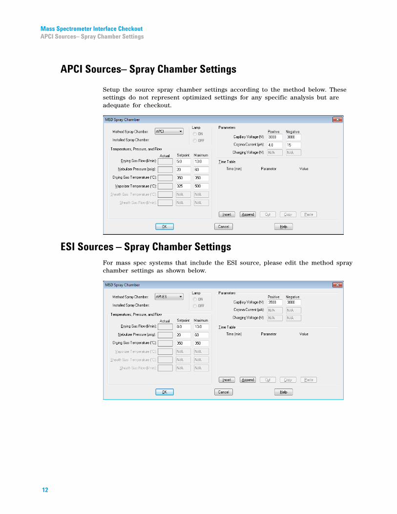
Setup the source spray chamber settings according to the method below. These settings do not represent optimized settings for any specific analysis but are adequate for checkout.
ESI Sources – Spray Chamber Settings
For mass spec systems that include the ESI source, please edit the method spray chamber settings as shown below.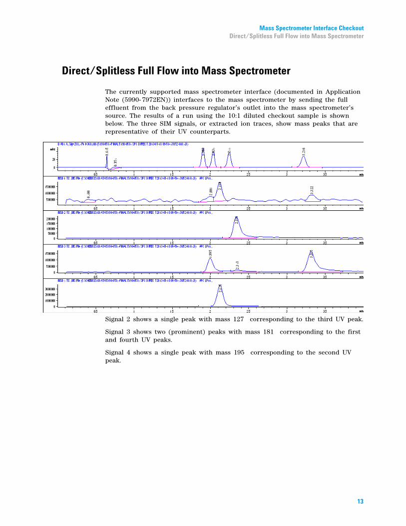
Mass Spectrometer Interface CheckoutDirect/Splitless Full Flow into Mass Spectrometer
Direct/Splitless Full Flow into Mass Spectrometer
The currently supported mass spectrometer interface (documented in Application Note (5990- 7972EN)) interfaces to the mass spectrometer by sending the full effluent from the back pressure regulator’s outlet into the mass spectrometer’s source. The results of a run using the 10:1 diluted checkout sample is shown below. The three SIM signals, or extracted ion traces, show mass peaks that are representative of their UV counterparts.
Signal 2 shows a single peak with mass 127 corresponding to the third UV peak.
Signal 3 shows two (prominent) peaks with mass 181 corresponding to the first and fourth UV peaks.
Signal 4 shows a single peak with mass 195 corresponding to the second UV peak.
13

Mass Spectrometer Interface Checkout Split Flow into Mass Spectrometer
Split Flow into Mass Spectrometer
14
An alternate means of interfacing to a mass spectrometer is using a high pressure split immediately after the diode array detector and before the inlet to the back pressure regulator. The advantage of a split approach is that peak shape is maintained since peak broadening through the BPR is avoided. It is critical that only the recommended splitter is used for this setup.
Below is a run using identical method conditions as used above with the same 10:1 diluted checkout sample. This run demonstrates similar characteristics with the direct/splitless approach. As with the direct approach, our checkout criteria is limited to the presence of a single peak in signal 2 with mass 127 , a pair of (prominent) peaks in signal 3 with a mass of 181 , and a single peak in signal 4 with a mass of 195 .
When the above method is run with a 10:1 dilution of the checkout sample, the four compounds are easily identified in the SIM traces. The presence of one single peak in Signal 2, two (prominent) peaks in Signal 3, and one single peak in Signal 4 is sufficient to demonstrate the operation of the SFC interface.

Hybrid Systems – UHPLC CheckoutCreate UHPLC_Checkout.M
Hybrid Systems – UHPLC Checkout
The checkout for Hybrid SFC/UHPLC and Hybrid SFC/UHPLC MS systems are nearly identical to the standard SFC systems as mentioned previously with only the addition of verifying the UHPLC mode separately. Instrument checkout of the UHPLC side of a hybrid system will utilize the same solvents, sample, and type column as the SFC side. The UHPLC checkout uses a very non- traditional mobile phase of water/methanol on a Zorbax Rx- Sil column. This method is sufficient to demonstrate the operation of the system, without requiring solvents and columns not used by SFC. However, the chromatographic separation could be improved using other traditional UHPLC mobile phase components and columns.
Create UHPLC_Checkout.M
The method SFC_Checkout.M can be loaded and edited as follows:Table 6 Method settings for SFC_Checkout.M
SFC Control Module (G4301)
SFC Method UNCHECKED
SFC Pump (G4302A)
Flow Rate 0.0 mL/min
UHPLC Pump (Quat, G1311B)
Flow Rate 1.0 mL/min
Solvent A ON, 90 % water
Solvent B ON, 10 % methanol
TCC Cluster/ TCC (G1316C)
Column Rx-Sil 4.6 mm x 150 mm, 5 µm*
Valving Set as required for UHPLC mode
Save this method as UHPLC_Checkout.M Loading this method will place the SFC Control Module in Standby.
* See note below
NOTE It is highly recommended that the same column is not used for both UHPLC and SFC modes in normal use.
When switching between UHPLC to SFC, the presence of water in the column combined with the de- compressive cooling of CO2 can lead to the formation of water ice and cause blockages. In the event that the same column must be used, it is recommended to flush the column with pure methanol for at least 5 column volumes in UHPLC mode before switching to SFC mode. Once the valving is switched to SFC mode, the flow rate should be kept low (1 mL/min, 30 % methanol) for a few column volumes to prevent over pressures. After a few
15
16
Hybrid Systems – UHPLC Checkout Perform a Single Run
column volumes are pumped, and the excess methanol is flushed from the column, the column head pressure will significantly decrease. Once the column head pressure is reduced and stable, the switching procedure is complete. This flushing with methanol should remove sufficient water to minimize the formation of water ice. A ‘mode switch’ method can be created using the method options of the valve screens to automate this behavior.
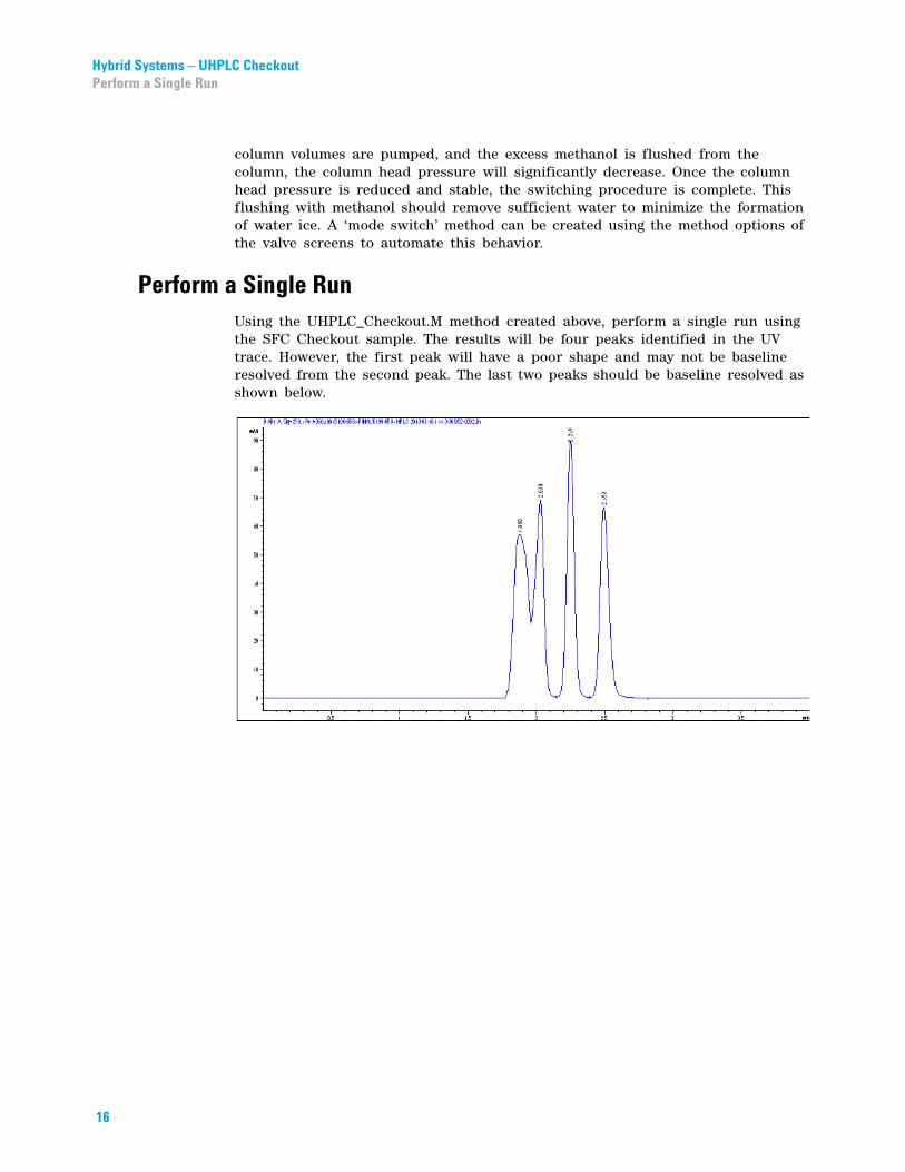
Perform a Single Run
Using the UHPLC_Checkout.M method created above, perform a single run using the SFC Checkout sample. The results will be four peaks identified in the UV trace. However, the first peak will have a poor shape and may not be baseline resolved from the second peak. The last two peaks should be baseline resolved as shown below.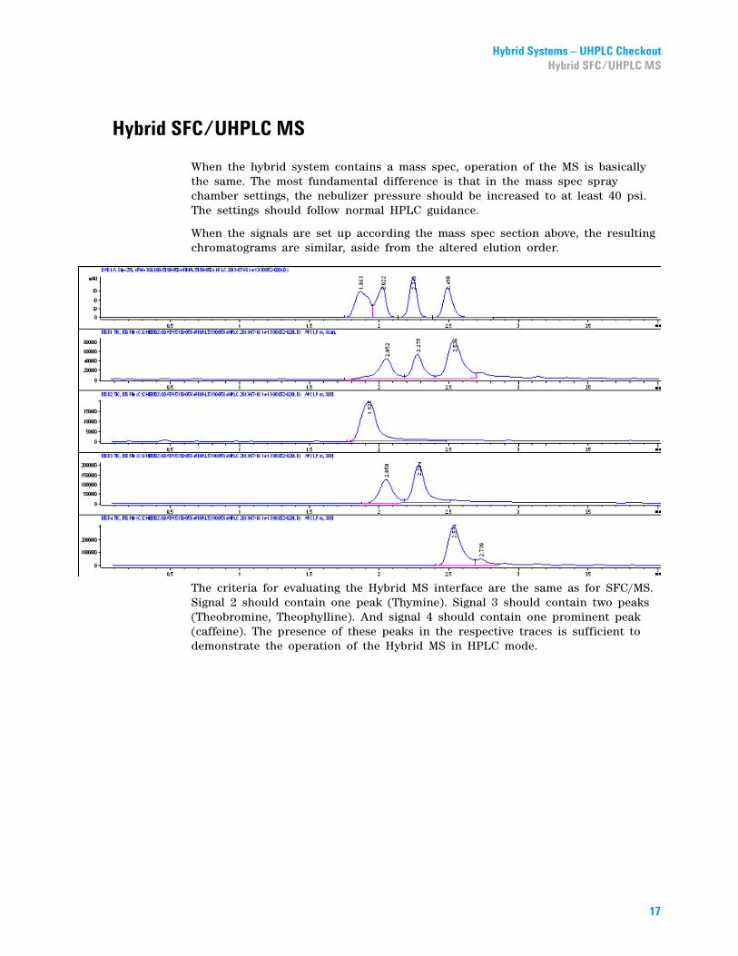
Hybrid Systems – UHPLC CheckoutHybrid SFC/UHPLC MS
Hybrid SFC/UHPLC MS
When the hybrid system contains a mass spec, operation of the MS is basically the same. The most fundamental difference is that in the mass spec spray chamber settings, the nebulizer pressure should be increased to at least 40 psi. The settings should follow normal HPLC guidance.
When the signals are set up according the mass spec section above, the resulting chromatograms are similar, aside from the altered elution order.
The criteria for evaluating the Hybrid MS interface are the same as for SFC/MS. Signal 2 should contain one peak (Thymine). Signal 3 should contain two peaks (Theobromine, Theophylline). And signal 4 should contain one prominent peak (caffeine). The presence of these peaks in the respective traces is sufficient to demonstrate the operation of the Hybrid MS in HPLC mode.
17

18
Hybrid Systems – UHPLC Checkout Hybrid SFC/UHPLC MS

Hybrid Systems – UHPLC CheckoutHybrid SFC/UHPLC MS
19

Hybrid Systems – UHPLC Checkout Hybrid SFC/UHPLC MS
*G4309-90*G4309-90G4309-90110
110*110*
Part Number: G4309- 90110
Edition: 10/2013Printed in Germany
© Agilent Technologies, Inc 2013
Agilent Technologies, IncHewlett-Packard-Strasse 8
76337 WaldbronnGermany