agenda: day one 4-1 - pudn.comread.pudn.com/downloads157/sourcecode/embed/701548/primetime_… ·...
TRANSCRIPT

Unit 4: Constraining Internal Reg-Reg Paths4-1PrimeTime: Introduction to Static Timing Analysis
4-1
Constraining Internal Reg-Reg PathsPrimeTime: Introduction to Static Timing AnalysisSynopsys 34000-000-S16
Agenda: Day One
DAY1111 Register to Register Paths LabUnit
Reading Data3
Constraining Internal Reg-Reg Paths4
Writing Basic Tcl Constructs in PT 2
Introduction to Static Timing Analysis1
Welcome0i

Unit 4: Constraining Internal Reg-Reg Paths4-2PrimeTime: Introduction to Static Timing Analysis
4-2
Constraining Internal Reg-Reg PathsPrimeTime: Introduction to Static Timing AnalysisSynopsys 34000-000-S16
Unit Objectives
After completing this unit, you should be able to:
� Create a TCL script which fully constrains internal register-to-register paths for timing and environment
� Correlate the applied constraints from timing reports
� Model Pre layout non ideal clocks
� Constrain multiple synchronous clocks

Unit 4: Constraining Internal Reg-Reg Paths4-3PrimeTime: Introduction to Static Timing Analysis
4-3
Constraining Internal Reg-Reg PathsPrimeTime: Introduction to Static Timing AnalysisSynopsys 34000-000-S16
The Inputs and Outputs of PrimeTime
Reports
PrimeTime
Technology Libraries
SDFTiming
Models in .db format
Gate-LevelNetlist Constraints Exceptions
SetupFile
Log,Script Files
Our Focus

Unit 4: Constraining Internal Reg-Reg Paths4-4PrimeTime: Introduction to Static Timing Analysis
4-4
Constraining Internal Reg-Reg PathsPrimeTime: Introduction to Static Timing AnalysisSynopsys 34000-000-S16
Five Step Static Timing Analysis Flow
READREAD
CONSTRAINCONSTRAIN
EXCEPTIONSEXCEPTIONS
CHECKCHECK
ANALYZEANALYZE
Our Focus

Unit 4: Constraining Internal Reg-Reg Paths4-5PrimeTime: Introduction to Static Timing Analysis
4-5
Constraining Internal Reg-Reg PathsPrimeTime: Introduction to Static Timing AnalysisSynopsys 34000-000-S16
� Synchronous Designs:� Data arrives from a clocked device� Data goes to a clocked device
� Objective:� Define the timing constraints for all paths within a design:
� All input paths� The internal (register to register) paths� All output paths
Timing Goals: Synchronous Designs
y
Clock source
D Q D Q
Clk
Current_Design
FF1 FF2N S
u1u2 u3
u4
a
Network latencySource latency
Clock source
In this unit you will focus on the register-to-register paths (reg-to-reg). The discussion will cover input logic paths and output paths in the following unit.
Unit 4: Constraining Internal Reg-Reg Paths4-6PrimeTime: Introduction to Static Timing Analysis
4-6
Constraining Internal Reg-Reg PathsPrimeTime: Introduction to Static Timing AnalysisSynopsys 34000-000-S16
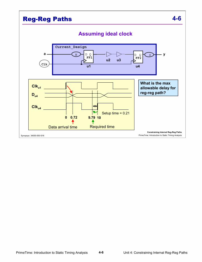
Reg-Reg Paths
Assuming ideal clock
D Q D Q
Clk
Current_Design
FF1 FF2N S
u1u2 u3
u4
a y
What is the max allowable delay for reg-reg path?
Setup time = 0.21
Clku1
Clku4
Du4
0 0.72 9.79 10
Required timeData arrival time

Unit 4: Constraining Internal Reg-Reg Paths4-7PrimeTime: Introduction to Static Timing Analysis
4-7
Constraining Internal Reg-Reg PathsPrimeTime: Introduction to Static Timing AnalysisSynopsys 34000-000-S16
Report: Reg-Reg Paths w/ Ideal Clock
Point Incr Path---------------------------------------------------------------clock Clk (rise edge) 0.00 0.00clock network delay (ideal) 0.00 0.00u1/CLK (fdef1a15) 0.00 0.00 ru1/Q (fdef1a15) 0.50 0.50 ru2/Y (buf1a27) 0.11 0.61 ru3/Y (buf1a27) 0.11 0.72 ru4/D (fdef1a15) 0.00 0.72 rdata arrival time 0.72
clock Clk (rise edge) 10.00 10.00clock network delay (ideal) 0.00 10.00u4/CLK (fdef1a15) 10.00 rlibrary setup time -0.21 9.79data required time 9.79---------------------------------------------------------------data required time 9.79data arrival time -0.72---------------------------------------------------------------slack (MET) 9.07
Period = 10
create_clock -period 10 [get_ports CLK]
Data Required Time
Data arrival time
Data Launch
Tclk = clock periodTu = clock uncertaintyTsl = source latencyTnl = network latentyTsu = flip-flop setup timeΣ Tcn = sum of all cell and net delay in the path
Data arrival time = Σ Tcn Data required time = Tclk - (Tsu)Data arrival time <= Data required time

Unit 4: Constraining Internal Reg-Reg Paths4-8PrimeTime: Introduction to Static Timing Analysis
4-8
Constraining Internal Reg-Reg PathsPrimeTime: Introduction to Static Timing AnalysisSynopsys 34000-000-S16
Specifying Constraint: Reg-Reg Paths
1 Clock Cycle
0 5 10Default 50% duty cycle
D Q D Q
Clk
Current_Design
FF1 FF2N S
u1u2 u3
u4
a y
Optional :-name clk_A (to assign clock name)-waveform {0, 6} (to define duty cycle and or offset/skew)
MUST Define: period and clock source (port/pin)
pt_shell> report_clock
pt_shell> create_clock -period 10 [get_ports Clk]
Creating a clock constrains all internal register to register timing paths.By default, duty cycle is assumed to be 50%. Therefore, if your duty cycle is other than 50% you would specify it using the “-waveform” option to the “create_clock” command. For example, to specify 40% duty cycle:create_clock -period 10 -waveform {0 4} [get_ports Clk]Use report_clock to see defined clocks and their attributes.When the create clock command is used as shown above, the port that is specified in the get_ports command (Clk in this example) will be designated as a clock object. If however, the –name switch is used, the clock object will be whatever name was specified in the –name switch.Example 1: create_clock -period 10 –name Mary [get_ports Clk]
clock object is named Mary.Example 2: create_clock -period 10 [get_ports Clk]
clock object is named Clk.This is important because there are some commands which require the clock object be specified (set_input_delay, set_output_delay) to be discussed in a subsequent unit.

Unit 4: Constraining Internal Reg-Reg Paths4-9PrimeTime: Introduction to Static Timing Analysis
4-9
Constraining Internal Reg-Reg PathsPrimeTime: Introduction to Static Timing AnalysisSynopsys 34000-000-S16
9.59.29 10
FF2 setup = 0.21 ns
Clku4
Clku1
0
Skew = 0.5 ns
Du4
0.72
PrimeTime applies skew/uncertainty to the capture edge.
Reg-Reg Paths w/ Clock Skew
Anticipate skew between launch and capture after layout
D Q
D Q
Clk
Current_Design
FF1
FF2
N
S
u1u2 u3
u4
a
yLonger delay
After layout
PT always applies clock uncertainty to the capture clock edge.setup check = (clock_edge - uncertainty - lib_setup)

Unit 4: Constraining Internal Reg-Reg Paths4-10PrimeTime: Introduction to Static Timing Analysis
4-10
Constraining Internal Reg-Reg PathsPrimeTime: Introduction to Static Timing AnalysisSynopsys 34000-000-S16
Report: Reg-Reg Paths With Clock Skew
Point Incr Path---------------------------------------------------------------clock Clk (rise edge) 0.00 0.00clock network delay (ideal) 0.00 0.00u1/CLK (fdef1a15) 0.00 0.00 ru1/Q (fdef1a15) 0.50 0.50 ru2/Y (buf1a27) 0.11 0.61 ru3/Y (buf1a27) 0.11 0.72 ru4/D (fdef1a15) 0.00 0.72 rdata arrival time 0.72
clock Clk (rise edge) 10.00 10.00clock network delay (ideal) 0.00 10.00clock uncertainty -0.50 9.50u4/CLK (fdef1a15) 9.50 rlibrary setup time -0.21 9.29data required time 9.29---------------------------------------------------------------data required time 9.29data arrival time -0.72---------------------------------------------------------------slack (MET) 8.57
Skew = 0.5
create_clock -period 10 [get_ports CLK]
set_clock_uncertainty 0.5 [get_clocks CLK]
Assume launch flop and capture flop are on opposite diagonals of the block.Assume launch flop clock path has largest possible delay with respect to capture flop clock path.Difference is called the setup uncertainty.Obtain uncertainty value (Tu) from vendor or layout person.PT always applies uncertainty to the capture flop.
Tclk = clock periodTu = clock uncertaintyTsl = source latencyTnl = network latentyTsu = flip-flop setup timeΣ Tcn = sum of all cell and net delay in the path
Data arrival time = Σ Tcn Data required time = Tclk - Tu - TsuData arrival time <= Data required time
Notice that PrimeTime always applies uncertainty to the capture edge.

Unit 4: Constraining Internal Reg-Reg Paths4-11PrimeTime: Introduction to Static Timing Analysis
4-11
Constraining Internal Reg-Reg PathsPrimeTime: Introduction to Static Timing AnalysisSynopsys 34000-000-S16
Reg-Reg Paths w/ Latency
Taking into account the delay due to clock tree insertion
D Q D Q
Clk
Current_Design
FF1 FF2N S
u1u2 u3
u4
a y
Network latency
Clku4
Clku1
Skew= 0.5
Clk
Network latency = 11 1110.29
Setup = 0.21
Du4
1.72
Unit 4: Constraining Internal Reg-Reg Paths4-12PrimeTime: Introduction to Static Timing Analysis
4-12
Constraining Internal Reg-Reg PathsPrimeTime: Introduction to Static Timing AnalysisSynopsys 34000-000-S16
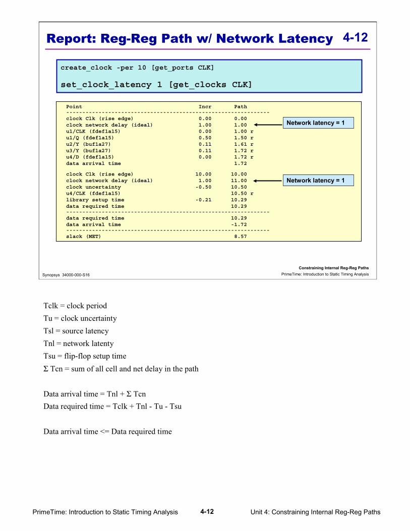
Report: Reg-Reg Path w/ Network Latency
Point Incr Path---------------------------------------------------------------clock Clk (rise edge) 0.00 0.00clock network delay (ideal) 1.00 1.00u1/CLK (fdef1a15) 0.00 1.00 ru1/Q (fdef1a15) 0.50 1.50 ru2/Y (buf1a27) 0.11 1.61 ru3/Y (buf1a27) 0.11 1.72 ru4/D (fdef1a15) 0.00 1.72 rdata arrival time 1.72
clock Clk (rise edge) 10.00 10.00clock network delay (ideal) 1.00 11.00clock uncertainty -0.50 10.50u4/CLK (fdef1a15) 10.50 rlibrary setup time -0.21 10.29data required time 10.29---------------------------------------------------------------data required time 10.29data arrival time -1.72---------------------------------------------------------------slack (MET) 8.57
Network latency = 1
Network latency = 1
create_clock -per 10 [get_ports CLK]
set_clock_latency 1 [get_clocks CLK]
Tclk = clock periodTu = clock uncertaintyTsl = source latencyTnl = network latentyTsu = flip-flop setup timeΣ Tcn = sum of all cell and net delay in the path
Data arrival time = Tnl + Σ Tcn Data required time = Tclk + Tnl - Tu - Tsu
Data arrival time <= Data required time

Unit 4: Constraining Internal Reg-Reg Paths4-13PrimeTime: Introduction to Static Timing Analysis
4-13
Constraining Internal Reg-Reg PathsPrimeTime: Introduction to Static Timing AnalysisSynopsys 34000-000-S16
Reg-Reg Path with Source Latency
Taking into account clock source latency
y
Clock source
D Q D Q
Clk
Current_Design
FF1 FF2N S
u1u2 u3
u4
a
Network latencySource latency
Clock source
Skew = 0.5
Clku4
Clku1
4
Clk
Network latency = 1
Clock source
Source latency = 3 14Setup = 0.21
13.29
Du4
4.72

Unit 4: Constraining Internal Reg-Reg Paths4-14PrimeTime: Introduction to Static Timing Analysis
4-14
Constraining Internal Reg-Reg PathsPrimeTime: Introduction to Static Timing AnalysisSynopsys 34000-000-S16
Report: Reg-Reg Path w/ Source Latency
Point Incr Path---------------------------------------------------------------clock Clk (rise edge) 0.00 0.00clock network delay (ideal) 4.00 4.00u1/CLK (fdef1a15) 0.00 4.00 ru1/Q (fdef1a15) 0.50 4.50 ru2/Y (buf1a27) 0.11 4.61 ru3/Y (buf1a27) 0.11 4.72 ru4/D (fdef1a15) 0.00 4.72 rdata arrival time 4.72
clock Clk (rise edge) 10.00 10.00clock network delay (ideal) 4.00 14.00clock uncertainty -0.50 13.50u4/CLK (fdef1a15) 13.50 rlibrary setup time -0.21 13.29data required time 13.29---------------------------------------------------------------data required time 13.29data arrival time -4.72---------------------------------------------------------------slack (MET) 8.57
Network latency = 1 source latency = 3
Network latency = 1 source latency = 3
create_clock -per 10 [get_ports CLK]
set_clock_latency 1 [get_clocks CLK]
set_clock_latency -source 3 [get_clocks CLK]
Tclk = clock periodTu = clock uncertaintyTsl = source latencyTnl = network latentyTsu = flip-flop setup timeΣ Tcn = sum of all cell and net delay in the path
Data arrival time = Tsl + Tnl + Σ Tcn Data required time = Tclk + Tsl + Tnl - Tu - Tsu
Data arrival time <= Data required time

Unit 4: Constraining Internal Reg-Reg Paths4-15PrimeTime: Introduction to Static Timing Analysis
4-15
Constraining Internal Reg-Reg PathsPrimeTime: Introduction to Static Timing AnalysisSynopsys 34000-000-S16
Reg-Reg Paths w/ Jitter
Taking into account clock jitter
early latency = 2.5 late latency = 3.5
y
Clock source
D Q D Q
Clk
Current_Design
FF1 FF2N S
u1
u2 u3
u4
a
Network latencySource latency
Clock source
Jitter = +/- 0.5 ns
Clk
Clklate
Clkearly
Clock source
early
late
2.53.0
3.50
J = jitterJitter is the variation of clock period from edge to edge. The period of the clock can vary by +/- j.

Unit 4: Constraining Internal Reg-Reg Paths4-16PrimeTime: Introduction to Static Timing Analysis
4-16
Constraining Internal Reg-Reg PathsPrimeTime: Introduction to Static Timing AnalysisSynopsys 34000-000-S16
Specifying Jitter
create_clock -period 10 [get_ports CLK]
set_clock_latency 2.5 -source -early [get_clocks CLK]
set_clock_latency 3.5 -source -late [get_clocks CLK]
CLK Ideal
0 5 10
CLK withsource latencyand jitter
2.5 3.5 12.5 13.5
Under worst caseconditions the jitter shortens theeffective clock period as shown.
Late Latency Late Latency Early Latency Early Latency
How do you specify jitter using set_clock_latency -source -early/-late?For late latency, the value is 3.5 - 0 = 3.5 (see the above timing diagram).For early latency, the value is 12.5 - 10 = 2.5 (see the above timing diagram).
It is possible to get a negative values for early and late latency. For example: if the source latency + the network latency is less than the jitter value, you can get a negative early latency.

Unit 4: Constraining Internal Reg-Reg Paths4-17PrimeTime: Introduction to Static Timing Analysis
4-17
Constraining Internal Reg-Reg PathsPrimeTime: Introduction to Static Timing AnalysisSynopsys 34000-000-S16
Report: Reg-Reg Paths w/ Clock Jitter
Point Incr Path---------------------------------------------------------------clock Clk (rise edge) 0.00 0.00clock network delay (ideal) 4.50 4.50u1/CLK (fdef1a15) 0.00 4.50 ru1/Q (fdef1a15) 0.50 5.00 ru2/Y (buf1a27) 0.11 5.11 ru3/Y (buf1a27) 0.11 5.22 ru4/D (fdef1a15) 0.00 5.22 rdata arrival time 5.22
clock Clk (rise edge) 10.00 10.00clock network delay (ideal) 3.50 13.50clock uncertainty -0.50 13.00u4/CLK (fdef1a15) 13.00 rlibrary setup time -0.21 12.79data required time 12.79---------------------------------------------------------------data required time 12.79data arrival time -5.22---------------------------------------------------------------slack (MET) 7.57
Network latency = 1 late source latency = 3.5
Network latency = 1 early source latency = 2.5
create_clock -period 10 [get_ports CLK]
set_clock_latency 1 [get_clocks CLK]
set_clock_uncertainty –setup 0.5 [get_clocks CLK]
set_clock_latency 2.5 -source -early [get_clocks CLK]
set_clock_latency 3.5 -source -late [get_clocks CLK]
Tclk = clock periodTu = clock uncertaintyTsl = source latencyTnl = network latentyTsu = flip-flop setup timeΣ Tcn = sum of all cell and net delay in the path
Data arrival time = Tsl(late) + Tnl + Σ Tcn Data required time = Tclk + Tsl(early) + Tnl - Tu - TsuData arrival time <= Data required time
Unit 4: Constraining Internal Reg-Reg Paths4-18PrimeTime: Introduction to Static Timing Analysis
4-18
Constraining Internal Reg-Reg PathsPrimeTime: Introduction to Static Timing AnalysisSynopsys 34000-000-S16
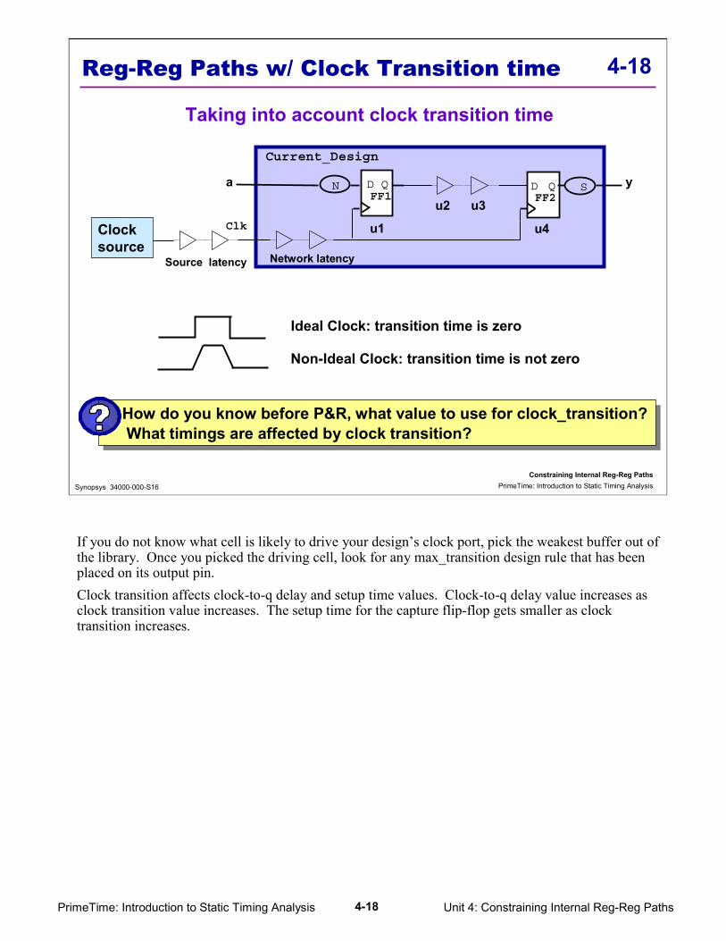
Reg-Reg Paths w/ Clock Transition time
Taking into account clock transition time
y
Clock source
D Q D Q
Clk
Current_Design
FF1 FF2N S
u1
u2 u3
u4
a
Network latencySource latency
Clock source
Ideal Clock: transition time is zero
Non-Ideal Clock: transition time is not zero
How do you know before P&R, what value to use for clock_transition?What timings are affected by clock transition?
How do you know before P&R, what value to use for clock_transition?What timings are affected by clock transition?
If you do not know what cell is likely to drive your design’s clock port, pick the weakest buffer out of the library. Once you picked the driving cell, look for any max_transition design rule that has been placed on its output pin.Clock transition affects clock-to-q delay and setup time values. Clock-to-q delay value increases as clock transition value increases. The setup time for the capture flip-flop gets smaller as clock transition increases.
Unit 4: Constraining Internal Reg-Reg Paths4-19PrimeTime: Introduction to Static Timing Analysis
4-19
Constraining Internal Reg-Reg PathsPrimeTime: Introduction to Static Timing AnalysisSynopsys 34000-000-S16
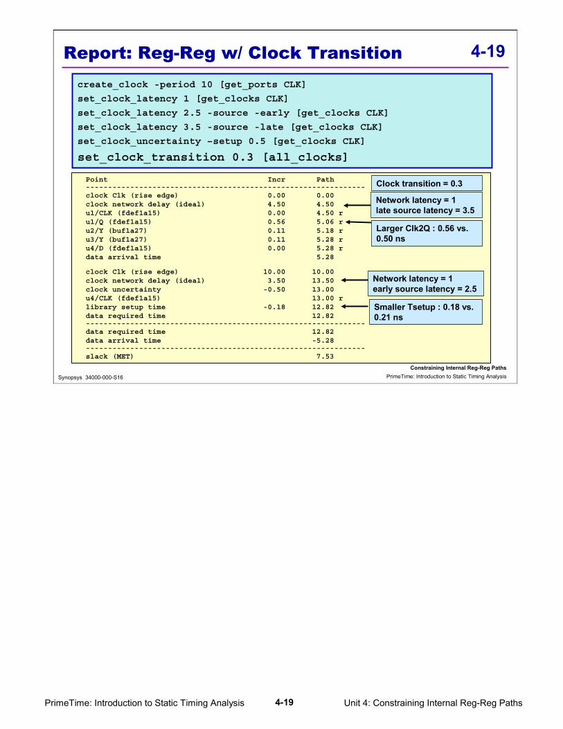
Report: Reg-Reg w/ Clock Transitioncreate_clock -period 10 [get_ports CLK]
set_clock_latency 1 [get_clocks CLK]
set_clock_latency 2.5 -source -early [get_clocks CLK]
set_clock_latency 3.5 -source -late [get_clocks CLK]
set_clock_uncertainty –setup 0.5 [get_clocks CLK]
set_clock_transition 0.3 [all_clocks]
Point Incr Path---------------------------------------------------------------clock Clk (rise edge) 0.00 0.00clock network delay (ideal) 4.50 4.50u1/CLK (fdef1a15) 0.00 4.50 ru1/Q (fdef1a15) 0.56 5.06 ru2/Y (buf1a27) 0.11 5.18 ru3/Y (buf1a27) 0.11 5.28 ru4/D (fdef1a15) 0.00 5.28 rdata arrival time 5.28
clock Clk (rise edge) 10.00 10.00clock network delay (ideal) 3.50 13.50clock uncertainty -0.50 13.00u4/CLK (fdef1a15) 13.00 rlibrary setup time -0.18 12.82data required time 12.82---------------------------------------------------------------data required time 12.82data arrival time -5.28---------------------------------------------------------------slack (MET) 7.53
Network latency = 1 late source latency = 3.5
Network latency = 1 early source latency = 2.5
Clock transition = 0.3
Larger Clk2Q : 0.56 vs. 0.50 ns
Smaller Tsetup : 0.18 vs. 0.21 ns

Unit 4: Constraining Internal Reg-Reg Paths4-20PrimeTime: Introduction to Static Timing Analysis
4-20
Constraining Internal Reg-Reg PathsPrimeTime: Introduction to Static Timing AnalysisSynopsys 34000-000-S16
Rise Fall Hold SetupObject Delay Delay Uncertainty Uncertainty--------------------------------------------------------------------------------Clk 1.00 1.00 0.50 0.50
Source LatencyObject Early Rise Early Fall Late Rise Late fall--------------------------------------------------------------------------------Clk 2.50 2.50 3.50 3.50
Rise FallObject Transition Transition--------------------------------------------------------------------------------Clk 0.30 0.30
Clock Period Waveform Attrs Sources-------------------------------------------------------------------------------Clk 10.00 {0 5} {Clk}
Reporting Clock Information
Latency = 1.00 ns
Uncertainty = 0.50 ns
Source early latency = 2.5 ns
Source late latency = 3.5 ns
Clock Transition = 0.30 ns
Clock Period = 10 ns
Duty Cycle = 50%
report_clock –skew -attribute

Unit 4: Constraining Internal Reg-Reg Paths4-21PrimeTime: Introduction to Static Timing Analysis
4-21
Constraining Internal Reg-Reg PathsPrimeTime: Introduction to Static Timing AnalysisSynopsys 34000-000-S16
Test For Understanding
� Which of the following is (are) normally used to add pessimism (or margin)?
a) Network latencyb) Source latency with –early and –late (jitter)c) Setup uncertaintyd) Clock transitione) All of the above
� Using what report can you find the clock transition amount specified?__________________________
� What is the effect of clock transition: (Circle all that apply)a) Increases (or decreases) the network latency (insertion delay)b) Increases (or decreases) the source latencyc) Increases (or decreases) the register propagation delay and setup timed) All of the above

Unit 4: Constraining Internal Reg-Reg Paths4-22PrimeTime: Introduction to Static Timing Analysis
4-22
Constraining Internal Reg-Reg PathsPrimeTime: Introduction to Static Timing AnalysisSynopsys 34000-000-S16
Multiple Synchronous Clocks
D Q D Q
Current_Design
FF1 FF2N S
u1 u2 u3u4
a y
÷6
300 MHzClk2
Clk1÷9
10 20 30 40 50 600
Clk1
Clk2
10 ns
30 40
Clk1
Clk2
39.79
Setup = 0.21
30.72
Du4
The common base for Clk1 and Clk2 is 60ns.There are two possible scenarios:
1) Clk1 launches at 0ns, Clk2 captures at 20ns.2) Clk1 launches at 30ns, Clk2 captures at 40ns.
Scenario 2 is the tightest time wise. PrimeTime uses scenario 2 to check setup violation.

Unit 4: Constraining Internal Reg-Reg Paths4-23PrimeTime: Introduction to Static Timing Analysis
4-23
Constraining Internal Reg-Reg PathsPrimeTime: Introduction to Static Timing AnalysisSynopsys 34000-000-S16
Report: Multiple Synchronous Clocks
Point Incr Path---------------------------------------------------------------clock Clk1 (rise edge) 30.00 30.00clock network delay (ideal) 0.00 30.00u1/CLK (fdef1a15) 0.00 30.00 ru1/Q (fdef1a15) 0.50 30.50 ru2/Y (buf1a27) 0.11 30.61 ru3/Y (buf1a27) 0.11 30.72 ru4/D (fdef1a15) 0.00 30.72 rdata arrival time 30.72
clock Clk2 (rise edge) 40.00 40.00clock network delay (ideal) 0.00 40.00u4/CLK (fdef1a15) 40.00 rlibrary setup time -0.21 39.79data required time 39.79---------------------------------------------------------------data required time 39.79data arrival time -30.72---------------------------------------------------------------slack (MET) 9.07
create_clock -period 30 [get_ports Clk1]
create_clock -period 20 [get_ports Clk2]
Capture Edge = 40 ns
Launch Edge = 30 ns Launch Edge = 30 ns
Launch Edge = 30 ns Setup Time = 0.21 ns

Unit 4: Constraining Internal Reg-Reg Paths4-24PrimeTime: Introduction to Static Timing Analysis
4-24
Constraining Internal Reg-Reg PathsPrimeTime: Introduction to Static Timing AnalysisSynopsys 34000-000-S16
Uncertainties with Multiple Clocks
D Q D Q
Current_Design
FF1 FF2N S
u1 u2 u3u4
a y
÷6
300 MHzClk2
Clk1÷9
Clk1 uncertainty = 0.15 ns
Clk2 uncertainty = 0.20 ns
What uncertainty does PT use for the path between registers?
6010 20 30 40 500
Clk1
Clk2
10 ns
30 40
Clk1
Clk2
39.59
Setup = 0.21
30.72
Du4
skew = 0.20skew = 0.15 (?)

Unit 4: Constraining Internal Reg-Reg Paths4-25PrimeTime: Introduction to Static Timing Analysis
4-25
Constraining Internal Reg-Reg PathsPrimeTime: Introduction to Static Timing AnalysisSynopsys 34000-000-S16
Report: Multi-synch. Clocks w/ Uncertaintycreate_clock -p 30 [get_ports Clk1]
create_clock -p 20 [get_ports Clk2]
set_clock_uncertainty –setup 0.15 [get_clocks Clk1]
set_clock_uncertainty –setup 0.20 [get_clocks Clk2]
Point Incr Path---------------------------------------------------------------clock Clk1 (rise edge) 30.00 30.00clock network delay (ideal) 0.00 30.00u1/CLK (fdef1a15) 0.00 30.00 ru1/Q (fdef1a15) 0.50 30.50 ru2/Y (buf1a27) 0.11 30.61 ru3/Y (buf1a27) 0.11 30.72 ru4/D (fdef1a15) 0.00 30.72 rdata arrival time 30.72
clock Clk2 (rise edge) 40.00 40.00clock network delay (ideal) 0.00 40.00clock uncertainty -0.20 39.80u4/CLK (fdef1a15) 39.80 rlibrary setup time -0.21 39.59data required time 39.59---------------------------------------------------------------data required time 39.59data arrival time -30.72---------------------------------------------------------------slack (MET) 8.87
Clock uncertainty = 0.20
Launch Edge = 30 ns Launch Edge = 30 ns
No uncertainty at launch
Launch Edge = 30 ns Capture Edge = 40 ns
Launch Edge = 30 ns Setup Time = 0.21 ns

Unit 4: Constraining Internal Reg-Reg Paths4-26PrimeTime: Introduction to Static Timing Analysis
4-26
Constraining Internal Reg-Reg PathsPrimeTime: Introduction to Static Timing AnalysisSynopsys 34000-000-S16
Uncertainties Between Sync. Clockscreate_clock -p 30 [get_ports Clk1]
create_clock -p 20 [get_ports Clk2]
set_clock_uncertainty 0.35 -setup \
-from [get_clocks Clk1] -to [get_clocks Clk2]
Point Incr Path---------------------------------------------------------------clock Clk1 (rise edge) 30.00 30.00clock network delay (ideal) 0.00 30.00u1/CLK (fdef1a15) 0.00 30.00 ru1/Q (fdef1a15) 0.50 30.50 ru2/Y (buf1a27) 0.11 30.61 ru3/Y (buf1a27) 0.11 30.72 ru4/D (fdef1a15) 0.00 30.72 rdata arrival time 30.72
clock Clk2 (rise edge) 40.00 40.00clock network delay (ideal) 0.00 40.00clock uncertainty -0.35 39.65u4/CLK (fdef1a15) 39.65 rlibrary setup time -0.21 39.44data required time 39.44---------------------------------------------------------------data required time 39.44data arrival time -30.72---------------------------------------------------------------slack (MET) 8.72
Clock uncertainty = 0.35
Launch Edge = 30 ns Launch Edge = 30 ns
No uncertainty at launch
Launch Edge = 30 ns Capture Edge = 40 ns
Launch Edge = 30 ns Setup Time = 0.21 ns

Unit 4: Constraining Internal Reg-Reg Paths4-27PrimeTime: Introduction to Static Timing Analysis
4-27
Constraining Internal Reg-Reg PathsPrimeTime: Introduction to Static Timing AnalysisSynopsys 34000-000-S16
Summary of Modeling Non-ideal Clocks
� set_clock_latency
� Models network delay (insertion delay) encountered within current_design
� set_clock_latency -source
� Models delay before reaching clock port of current_design
� set_clock_latency –source –early -late
� Models delay including external jitter before reaching clock port of current_design
� set_clock_uncertainty
� Models uncertainty (skew) between clock tree branches
� set_clock_transition
� Models clock transition time (slew)
Where to get numbers for the above spec?- Ask for recommendations from the Clock Tree Synthesis Vendor/Tool for information on network delay and the maximum guaranteed skew between clock branches.- Ask your System Engineer about Source Latency. How far is the clock source (crystal/PLL) going to placed on the chip from your design’s Clock port. Is Top Level Floor plan available?- Ask the Layout Engineer if he/she expects any Timing margin so that you can include it as part of the skew specification in order to be more pessimistic

Unit 4: Constraining Internal Reg-Reg Paths4-28PrimeTime: Introduction to Static Timing Analysis
4-28
Constraining Internal Reg-Reg PathsPrimeTime: Introduction to Static Timing AnalysisSynopsys 34000-000-S16
Environmental Attributes?
Under what process,voltage, and temperature
conditions will PTcalculate the path
delays?
D Q D Q D QD Q
Clk The_Current_Design
FF1 FF2 FF3 FF4M N X S T
Which wire load modelwill PT use to estimate
the pre-layout net parasitic data?

Unit 4: Constraining Internal Reg-Reg Paths4-29PrimeTime: Introduction to Static Timing Analysis
4-29
Constraining Internal Reg-Reg PathsPrimeTime: Introduction to Static Timing AnalysisSynopsys 34000-000-S16
Specifying Wire Load Model
SUBDES_B
SUBDES_A
U1MY_DES
U33
� To specify a single WLM for all the nets in the design:
� To specify a “larger” WLM for the boundary nets:
50KGATES
set_wire_load_model -name 40KGATES [current_design]
set_wire_load_model -name 80KGATES [get_ports *]
Recall from Unit-1 that a wire load model is a table for estimating the capacitance, resistance and area of a net. It is based on a statistical correlation between net fanout and net parasitics.
Use report_lib libname to list the vendor-supplied wire load models.
R1
C1R2 C2

Unit 4: Constraining Internal Reg-Reg Paths4-30PrimeTime: Introduction to Static Timing Analysis
4-30
Constraining Internal Reg-Reg PathsPrimeTime: Introduction to Static Timing AnalysisSynopsys 34000-000-S16
Automatic Selection of Wire Load Model
Turn off automatic wire load model selection with:
pt_shell> printvar *wire*
pt_shell> set auto_wire_load_selection false
pt_shell> report_lib ssc_core_slow
Name----------------------------------5KGATES10KGATES20KGATES40KGATES80KGATES
….AreaBasedWireLoadSelection
By default the variable auto_wire_load_selection is true.

Unit 4: Constraining Internal Reg-Reg Paths4-31PrimeTime: Introduction to Static Timing Analysis
4-31
Constraining Internal Reg-Reg PathsPrimeTime: Introduction to Static Timing AnalysisSynopsys 34000-000-S16
Specifying Wire Load Mode
SUBDES_B
SUBDES_A
U1MY_DES
U33
40KGATES
20KGATES
� With the mode enclosed, the wire load model which fully encloses each net is used
� With the mode top used on the top level design, all nets in the design use the Top level WLM
20KGATES
set_wire_load_model -name 40KGATES [current_design]
set_wire_load_model -name 20KGATES [get_cell U1]
set_wire_load_model -name 20KGATES [get_cell U33]
set_wire_load_mode enclosed
The default WLM mode is “top”If the library has a default wire load mode, then the default mode is used if user does not specifyone.

Unit 4: Constraining Internal Reg-Reg Paths4-32PrimeTime: Introduction to Static Timing Analysis
4-32
Constraining Internal Reg-Reg PathsPrimeTime: Introduction to Static Timing AnalysisSynopsys 34000-000-S16
Operating Condition Models
Library cells are usually characterized using “nominal” voltage and temperature.
What if the circuit is to operate at a voltage and/or temperature OTHER than nominal?
How is the delay through the net or cell affected?
bestnominal
worst
Process
Delay
Temperature
worstnominal
bestDelay Delay
Voltage
worstnominal
best

Unit 4: Constraining Internal Reg-Reg Paths4-33PrimeTime: Introduction to Static Timing Analysis
4-33
Constraining Internal Reg-Reg PathsPrimeTime: Introduction to Static Timing AnalysisSynopsys 34000-000-S16
Specifying Operating Conditions
� Operating Conditions specify:� A scaling (K) factor for the nominal cell, net delays and � A Tree Type representing the RC distribution or Interconnect
model of the nets, used in the net delay calculation
pt_shell> set_operating_conditions -max slow_125_1.62
pt_shell> report_lib ssc_core_slow
Operating Conditions:
Name Process Temp Voltage Tree Type---------------------------------------------------------------------slow_125_1.62 1.00 125.00 1.62 balanced_caseslow_125_1.62_WCT 1.00 125.00 1.62 worst_case
K = f (Process, Voltage, Temp)
If the library has a default operating conditions and user does not specify one, the default in the library will be used.

Unit 4: Constraining Internal Reg-Reg Paths4-34PrimeTime: Introduction to Static Timing Analysis
4-34
Constraining Internal Reg-Reg PathsPrimeTime: Introduction to Static Timing AnalysisSynopsys 34000-000-S16
Design Attribute Value---------------------------------------------------------------------------Operating Conditions:analysis_type singleoperating_condition_max_name slow_125_1.62process_max 1temperature_max 125voltage_max 1.62tree_type_max balanced_case
Wire Load: (use report_wire_load for more information)wire_load_mode topwire_load_model_max 40KGATESwire_load_model_library_max ssc_core_slowwire_load_selection_type_max user-specifiedwire_load_selection_group_max AreaBasedWireLoadSelectionwire_load_min_block_size 0
Reporting Environmental Information
report_design
WLM Mode = top
WLM = 40KGATES
Launch Edge = 30 ns Tree Type = balanced_case
Operating Condition name = slow_125_1.62

Unit 4: Constraining Internal Reg-Reg Paths4-35PrimeTime: Introduction to Static Timing Analysis
4-35
Constraining Internal Reg-Reg PathsPrimeTime: Introduction to Static Timing AnalysisSynopsys 34000-000-S16
Summary of Reg-Reg Path Constraints
create_clock -period 4.0 [get_ports Clk]
set_clock_latency 0.3 [get_clocks Clk]
set_clock_uncertainty 0.25 [get_clocks Clk]
set_clock_latency -source 0.5 [get_clocks Clk]
set_clock_transition 0.4 [get_clocks Clk]
set_wire_load_model -name 5KGATES
set_wire_load_mode TOP
set_operating_conditions -max slow_125_1.62
redirect reg2reg.rpt {report_clock -skew -attr}
redirect -append reg2reg.rpt {report_design}

Unit 4: Constraining Internal Reg-Reg Paths4-36PrimeTime: Introduction to Static Timing Analysis
4-36
Constraining Internal Reg-Reg PathsPrimeTime: Introduction to Static Timing AnalysisSynopsys 34000-000-S16
Lab Overview
� Given a specification (clock definitions, latencies, uncertainties), write a script file that constrains all the register to register paths in a design
� Generate several pre STA reports (such as the library report, clock report, design report) to ensure you’ve specified the constraints
� Discover the incompleteness of constraints (using check_timing) and generate timing report for the longest register to register path
� Experiment the effect of clock transition on the register propagation delay (Clk2Q), setup time and the amount of slack
LAB
45 min

Unit 4: Constraining Internal Reg-Reg Paths4-37PrimeTime: Introduction to Static Timing Analysis
4-37
Constraining Internal Reg-Reg PathsPrimeTime: Introduction to Static Timing AnalysisSynopsys 34000-000-S16
1. Between what clock edges you expect the setup time to be checkedbetween synchronous Clk1 (launch) and Clk2(capture) given the following specifications (Draw the waveform and answer this question).
� Between what clock edges you expect the setup time to be checkedbetween synchronous Clk1 (launch) and Clk2(capture) given the following specifications (Draw the waveform and answer this question).
3. With what command can you check the name of the library operating conditions set on your current_design? Use Quick Reference and your notes. (Circle all that apply).
a. report_libb. report_designc. report_operating_conditionsd. report_clock
Review
create_clock –period 10.0 [get_ports Clk1]
create_clock –period 15.0 –waveform {1 9} [get_ports Clk2]
create_clock –period 10.0 [get_ports Clk1]
create_clock –period 15.0 [get_ports Clk2]
set_clock_latency –rise 1.0 –fall 1.5 [get_clocks Clk2]

Unit 4: Constraining Internal Reg-Reg Paths4-38PrimeTime: Introduction to Static Timing Analysis
4-38
Constraining Internal Reg-Reg PathsPrimeTime: Introduction to Static Timing AnalysisSynopsys 34000-000-S16
Appendix
Reporting Hold Time violations
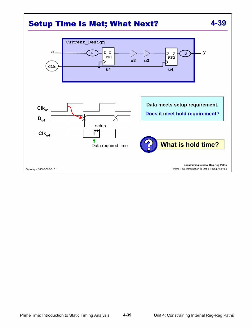
Unit 4: Constraining Internal Reg-Reg Paths4-39PrimeTime: Introduction to Static Timing Analysis
4-39
Constraining Internal Reg-Reg PathsPrimeTime: Introduction to Static Timing AnalysisSynopsys 34000-000-S16
Setup Time Is Met; What Next?
Data meets setup requirement.
Does it meet hold requirement?
What is hold time?
D Q D Q
Clk
Current_Design
FF1 FF2N S
u1
u2 u3
u4
a y
Clku1
Clku4
Du4
Data required time
setup

Unit 4: Constraining Internal Reg-Reg Paths4-40PrimeTime: Introduction to Static Timing Analysis
4-40
Constraining Internal Reg-Reg PathsPrimeTime: Introduction to Static Timing AnalysisSynopsys 34000-000-S16
Reg-Reg Path Hold Requirement
Assume FF2 hold time requirement is 0.23 ns.
What is the minimum delay requirement from FF1 to FF2?
D Q D Q
Clk
Current_Design
FF1 FF2N S
u1u2 u3
u4
a y
Hold time is an amount of time from the capture edge within which data has to remain stable.
Assuming ideal clock
Clku1
Clku4
Du4Hold = 0.23
0.750
Minimum delay from FF1 to FF2 must be equal to the hold time.

Unit 4: Constraining Internal Reg-Reg Paths4-41PrimeTime: Introduction to Static Timing Analysis
4-41
Constraining Internal Reg-Reg PathsPrimeTime: Introduction to Static Timing AnalysisSynopsys 34000-000-S16
Report: Reg-Reg Path Hold Requirement
create_clock -period 10 [get_ports CLK]
Point Incr Path---------------------------------------------------------------clock Clk (rise edge) 0.00 0.00clock network delay (ideal) 0.00 0.00u1/CLK (fdef1a15) 0.00 0.00 ru1/Q (fdef1a15) 0.48 0.48 fu2/Y (buf1a27) 0.14 0.62 fu3/Y (buf1a27) 0.14 0.75 fu4/D (fdef1a15) 0.00 0.75 fdata arrival time 0.75
clock Clk (rise edge) 0.00 0.00clock network delay (ideal) 0.00 0.00u4/CLK (fdef1a15) 0.00 rlibrary hold time 0.23 0.23data required time 0.23---------------------------------------------------------------data required time 0.23data arrival time -0.75---------------------------------------------------------------slack (MET) 0.53
Hold requirement = 0.23
ΣΣΣΣ Tcell = 0.75
Tclk = clock periodTu = clock uncertaintyTsl = source latencyTnl = network latentyTsu = flip-flop setup timeTh = flip-flop hold timeΣ Tcn = sum of all cell and net delay in the path
For hold:Data arrival time (Σ Tcn ) => Th

Unit 4: Constraining Internal Reg-Reg Paths4-42PrimeTime: Introduction to Static Timing Analysis
4-42
Constraining Internal Reg-Reg PathsPrimeTime: Introduction to Static Timing AnalysisSynopsys 34000-000-S16
Why Check Hold Before Layout?
� Usually hold is checked after layout under the best case conditions
� Prior to layout, hold may be checked under the worst case conditions to catch any large hold time violations
� Hold time requirements are affected by: � Skew on the clock tree network� Operating Conditions (discussed later in this unit) � FF Hold Time

Unit 4: Constraining Internal Reg-Reg Paths4-43PrimeTime: Introduction to Static Timing Analysis
4-43
Constraining Internal Reg-Reg PathsPrimeTime: Introduction to Static Timing AnalysisSynopsys 34000-000-S16
Hold Requirement w/ Latencies
Non-ideal clock w/ source and network latencies
y
Clock source
D Q D Q
Clk
Current_Design
FF1 FF2N S
u1u2 u3
u4
a
Network latency
Source latency
Clock source
skew = 0.5ns
Hold = 0.29
Clku1
Clku4
Du4
5.293.5 4.5
5.04.31
Network latency = 1 early latency = 2.5 late latency = 3.5 skew = +/- 0.5
Does this design meet the hold time requirement?
If not, how big is the violation?
PT always applies clock uncertainty to the capture clock edge.

Unit 4: Constraining Internal Reg-Reg Paths4-44PrimeTime: Introduction to Static Timing Analysis
4-44
Constraining Internal Reg-Reg PathsPrimeTime: Introduction to Static Timing AnalysisSynopsys 34000-000-S16
Report: Reg-to-Reg Hold w/ Latencies
Point Incr Path---------------------------------------------------------------clock Clk (rise edge) 0.00 0.00clock network delay (ideal) 3.50 3.50u1/CLK (fdef1a15) 0.00 3.50 ru1/Q (fdef1a15) 0.54 4.04 fu2/Y (buf1a27) 0.14 4.18 fu3/Y (buf1a27) 0.14 4.31 fu4/D (fdef1a15) 0.00 4.31 fdata arrival time 4.31
clock Clk (rise edge) 0.00 0.00clock network delay (ideal) 4.50 4.50clock uncertainty 0.50 5.00u4/CLK (fdef1a15) 5.00 rlibrary hold time 0.29 5.29data required time 5.29---------------------------------------------------------------data required time 5.29data arrival time -4.31---------------------------------------------------------------slack (VIOLATED) -0.97
early source latency = 2.5
Network latency = 1
late source latency = 3.5
Network latency = 1
create_clock -period 10 [get_ports CLK]
set_clock_latency 1 [get_clocks CLK]
set_clock_latency 2.5 -source -early [get_clocks CLK]
set_clock_latency 3.5 -source -late [get_clocks CLK]
When performing timing report for hold time in a single clock domain environment with jitter, you will get a pessimism equal to the jitter. In this example, you get a pessimism of 1 ns, so you have a positive slack of 0.03ns. In general, jitter is a very small percentage of clock period, therefore the pessimism can be ignored for most designs.In very high speed designs, the jitter may be a significant portion of the clock period.Under single clock environment and under best case condition, if early and late source latency are used to model jitter for register-to-register path timing analysis, you will get extra pessimism.