advances in ultrafast optics and imaging...
TRANSCRIPT
Advances in Ultrafast Optics and Imaging Applications
Guy Satata, Barmak Heshmata, Nikhil Naika, Albert Redo-Sancheza, and Ramesh Raskara
aMedia Lab, Massachusetts Institute of Technology, Cambridge MA, USA
ABSTRACT
Ultrafast imaging has been a key enabler to many novel imaging modalities, including looking behind cornersand imaging behind scattering layers. With picosecond time resolution and unconventional sensing geometries,ultrafast imaging can fundamentally impact sensing capabilities in industrial and biomedical applications. Thispaper reviews the fundamentals, recent advances, and the future prospects of ultrafast imaging-based modalities.
Keywords: Ultrafast Imaging, Computational Imaging
1. INTRODUCTION
The use of ultrafast imaging has been a fundamental piece to many advances in various imaging applications,including looking behind corners,1 imaging behind scattering layers2–4 and pose estimation.5 Critical compo-nents to these advances are emerging image sensors with picosecond (ps) time resolution, which enable accuratetemporal information acquisition without the need for conventional interferometric geometries.6 Typical com-putational imaging techniques in traditional scene analysis exploit sensor parameters such as spatial resolution,7
angular sensitivity,8 wavelength, and polarization.9 However, these parameters alone are limited in their abilityto capture the complex dynamics of light propagation. Ultrafast time-resolved sensors overcome this limitationand enable complicated analysis of light-in-flight in various imaging geometries.
One of the most notable applications of ultrafast optics is imaging beyond the conventional field of view ofthe camera. The sensor measures the time of flight (ToF) of indirect reflections from the hidden object, anda reconstruction algorithm is used to invert the measurements to recover the object. Based on the Plenopticfunction,10 light transport theory11 and the rendering equation,12 it has been shown that time-resolved imagingis especially suited for these applications.13
To use ultrafast measurements for sensing beyond line-of-sight or conventional field of view, we usually needto solve a complex inverse problem. A key insight in solving the inverse problem is to treat light propagationbetween the scene and sensors in a five dimensional space14 comprising of space (2D), angle (2D), and time(1D). Thus, by combining forward models of light propagation and advanced signal processing and optimizationtechniques, we are able to invert the measurement and recover the hidden scene.
In this paper we demonstrate how ultrafast imaging has enabled simultaneous localization and identificationof objects with temporal signatures hidden behind scattering layers. The paper is structured as follows: Section2 serves as an introduction to ultrafast optical measurement techniques. Section 3 discusses non-line of sightimaging in cases of discrete scattering events. Section 4 discusses non-line of sight imaging in cases where thetime dependency is a continuous function. Section 5 extends the discussion to the THz regime. Section 6discusses novel imaging architectures, and section 7 provides an insight to future ultrafast sensors and theirimaging applications.
2. IMAGING WITH ULTRAFAST OPTICS
A key component to ultrafast imaging is the ultrafast sensor. There is a broad range of sensors and sensor arraysthat can be used for time-resolved imaging with temporal resolution as low as the ultrafast pulse cycle itself.15–17
Despite the large diversity of sensors for this application, electronically-triggered sensors, such as streak cameraand single photon avalanche diode arrays (SPADs), are more common due to convenience in alignment and
Corresponding author email: [email protected]

Figure 1. Measurement and result of ultrafast imaging. (a) Streak image, y-axis represents time, x-axis represents spatialcoordinates. The target is a patch behind a thin di↵user. Each row represent a time window of 2ps. (b) Four frames froman ultrafast measurement. The target is a pulse of light propagating through a bottle. Measurements were taken using astreak camera and mechanical moving mirrors (scanning through the spatial y-axis).
Figure 2. Acquisition geometries for non-line of sight imaging using ultrafast optics. ‘T’ represents the target. ‘C’represents the camera (sensor), and ‘L’ represents the pulsed laser source. (a) Looking behind corner setup. Black linesare opaque di↵usive walls. (b) Imaging through di↵user, reflection mode. Gray line is a thin di↵usive sheet. (c) Imagingthrough di↵user, transmission mode. Yellow box is a volumetric di↵user.
acquisition. The use of electronic triggering through photodiode signal eliminates the need for precise opticaldelay lines and interferometric geometries.
Streak cameras are photocathode tubes that map the time axis onto the y-axis of a sensor (with 2ps timeresolution). This is achieved by deflecting photoexcited electrons inside the photocathode tube. The streakimage is thus an x � t image (Fig. 1a). In order to acquire the full x � y � t data cube, vertical scanning ofthe scene is needed. This can be done in a single shot by optical multiplexing18,19 or it can be done in periodicmode through mechanical scanning means. An example of an ultrafast scene captured with a streak cameraand mechanical scanning of the y-axis is shown in Fig. 1b.20 Full x � y � t scanning is not always necessary.Depending on the application, illumination scanning may replace the vertical scanning. This is known as dualphotography21 and will be demonstrated in multiple applications below.
Streak camera is especially proper for non-line of sight acquisition geometries as it provides nanosecond (ns)time window along with ps time resolution and ⇠ 1K pixels for spatial resolution. This is not the case for someother electronically triggered ultrafast sensors such as ICCDs22–24 and SPADs. Another aspect to consider isspectral sensitivity. The majority of the above sensors is broadband; however, since they are mostly based ondirect band gap photoexcitation in semiconductors, they lose their sensitivity in far IR and THz.25 For thesefrequencies, nonlinear optoelectronic approaches are paving the way for ultrafast imaging.26,27
Fig. 2 reviews three main geometries that use ultrafast measurement for non-line of sight imaging. Asexplained in the following sections, each geometry is better suited for imaging through a certain type of scattering

barriers. For example, reflective geometries allow imaging through discrete scattering barriers (Fig. 2a,b).Transmission geometries (Fig. 2c) are desired in case of volumetric scattering for improved signal-to-noise ratio(SNR).
3. IMAGING AFTER DISCRETE SCATTERING EVENTS
3.1 Looking Around Corners
Figure 3. Recovered geometry of hidden object. a) A photograph of a hidden mannequin. b) The recovered geometryusing ultrafast time-resolved measurement.
Consider an optical geometry of looking around a corner (Fig. 2a). Using ultrafast time-resolved measurementallows us to recover a mannequin (Fig. 3) hidden behind the corner.1,28 This is achieved by illuminating thefirst surface in front of the camera (a door) by a short laser pulse (⇠ 50fs). The pulse bounces o↵ the door andscatters in all directions. A small fraction of the light will travel into the room, scatter from the hidden objectthere and travel back, first to the door, and then to the camera. To increase the measurement diversity, it isrepeated 60 times, each measurement taken with a di↵erent illumination position on the door (using the conceptof dual photography21).
To reconstruct the hidden object using the ultrafast measurements, we first develop a mathematical modelwhich describes the image formation. Consider a hidden patch in position x
0, and illumination point on the wallx
l
. The captured time-resolved measurement at sensor position x and time t will be:
I
l
(x, t) = I0
Zg(x
l
, x, x
0)R(x0) ⇤t
�
�t� c
�1(rl
(x0) + r
c
(x0))�dx
0 (1)
where, I0 is the source intensity, and g(xl
, x, x
0) is a geometric factor which accounts for scene geometry. R(x0)is the reflectance of the patch. The �(·) function enforces the information cone defined by the speed of light c.Finally, r
l
and r
c
are the distances from the source to the patch and patch to camera, respectively. The goal isto recover the reflectance distribution R(x0) from the set of ultrafast measurements {I
l
(x, t)}l=1..60.
Using this forward model allows to scan through the target volume (x0) and compare the expected mea-surement to the actual measurement. The amount of overlap provides a confidence measure to the existence ofobject in that location. Repeating this process on the target volume and for all illumination points results inthe reconstruction in Fig. 3b.
3.2 Recovering Material Reflectances Behind Scattering Layer
Measuring the reflectance properties of materials—in the form of simple albedo or di↵use reflectivity (as discussedearlier), or complex Bidirectional Reflectance Distribution Functions—is useful for a variety of applications inOptics, Medical Imaging, and Computer Graphics. To demonstrate accurate recovery of these material propertiesbehind scattering layer,2,29,30 we employ the reflection optical geometry (Fig. 2b).

Figure 4. Recovering albedo behind di↵user. (a) Di↵user and hidden scene composed of multiple patches with di↵erentalbedos. (b) Ground truth albedos. (c) Recovered albedos. (d) Quantitative comparison of recovery to ground truth.
Figure 5. Acquiring parametric BRDFs. (a) Multiple material samples. (b) Indirect-imaging setup. (c) The recoveredBRDFs match well with the data acquired with traditional methods.
Similarly to the “looking around corners” case, we acquire time-space streak images by focusing on a singleline on the di↵user and illuminating it with pulsed laser on several locations. Using Eq. 1 we render syntheticstreak images based on the scene geometry, where the only unknown is the albedo of scene points (R(x0)). Wesolve a nonlinear optimization problem for scene point albedos, that minimizes the error norm between the realstreak images and the rendered streak images. We are able to accurately measure the albedo of several scenepoints in complex scenes (Fig. 4).
The Bidirectional Reflectance Distribution Function (BRDF) is a four-dimensional function that characterizesthe relationship between the reflected and incident radiance for opaque surfaces. BRDFs are primarily used inthe field of computer graphics for photorealistic rendering, image relighting, and material editing, as well asfor matching and material identification. Traditional techniques in graphics directly illuminate and image asmall sample of the material from various angles, to acquire material BRDFs (see31 for a survey on acquisitiontechniques). Traditional BRDF acquisition methods are time consuming, need complex equipment encirclingsmall material samples, and typically image only a single material at a time.
Ultrafast measurements enable us to tackle these challenges.30 Unlike traditional techniques which rely ondirect measurement of reflected light o↵ the material surface, ToF measures all the bounces of light arrivingat the di↵use surface, after interacting with material samples (Fig. 5). We acquire multiple streak images ofindirect reflections from samples. The measurements and scene geometry are used in a linear system to solvefor a low-dimensional parametric BRDF. We solve the linear system using unconstrained linear optimization, torecover BRDFs, which match well with BRDFs obtained with traditional methods, both in simulations and realexperiments.
4. IMAGING AFTER CONTINUOUS SCATTERING
This section extends the previous imaging applications to cases in which there is significant time blur (due tofluorescence or volumetric scattering). Thus, the time dependency is not parameterized by a discrete function.
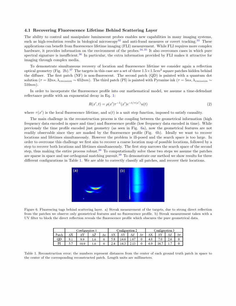
4.1 Recovering Fluorescence Lifetime Behind Scattering Layer
The ability to control and manipulate luminescent probes enables new capabilities in many imaging systems,such as high-resolution results in biological microscopy32 and anti-fraud measures or covert tracking.33 Theseapplications can benefit from fluorescence lifetime imaging (FLI) measurement. While FLI requires more complexhardware, it provides information on the environment of the probes.34,35 It also overcomes cases in which purespectral signature is insu�cient.36 In particular, the extra information provided by FLI makes it attractive forimaging through complex media.
To demonstrate simultaneous recovery of location and fluorescence lifetime we consider again a reflectionoptical geometry (Fig. 2b).37 The targets in this case are a set of three 1.5⇥1.5cm2 square patches hidden behindthe di↵user. The first patch (NF) is non-fluorescent. The second patch (QD) is painted with a quantum dotsolution (⌧ = 32ns,�
emission
⇠ 652nm). The third patch (PI) is painted with Pyranine ink (⌧ = 5ns,�emission
⇠510nm).
In order to incorporate the fluorescence profile into our mathematical model, we assume a time-defendantreflectance profile with an exponential decay in Eq. 1:
R(x0, t) = ⇢(x0)⌧�1(x0)e�t/⌧(x0)
u(t) (2)
where ⌧(x0) is the local fluorescence lifetime, and u(t) is a unit step function, imposed to satisfy causality.
The main challenge in the reconstruction process is the coupling between the geometrical information (highfrequency data encoded in space and time) and fluorescence profile (low frequency data encoded in time). Whilepreviously the time profile encoded just geometry (as seen in Fig. 6a), now the geometrical features are notreadily observable since they are masked by the fluorescence profile (Fig. 6b). Ideally we want to recoverlocations and lifetimes simultaneously. However the problem is ill-posed and the search space is too large. Inorder to overcome this challenge we first aim to recover a coarse location map of possible locations, followed by astep to recover both locations and lifetimes simultaneously. The first step narrows the search space of the secondstep, thus making the entire process robust.38 To computationally solve these two steps we assume the patchesare sparse in space and use orthogonal matching pursuit.39 To demonstrate our method we show results for threedi↵erent configurations in Table 1. We are able to correctly classify all patches, and recover their locations.
Figure 6. Fluorescing tags behind scattering layer. a) Streak measurement of the targets, due to strong direct reflectionfrom the patches we observe only geometrical features and no fluorescence profile. b) Streak measurement taken with aUV filter to block the direct reflection reveals the fluorescence profile which obscures the pure geometrical data.
Table 1. Reconstruction error; the numbers represent distances from the center of each ground truth patch in space tothe center of the corresponding reconstructed patch. Length units are millimeters.

4.2 Imaging Through Volumetric Scattering
Another case of ultrafast imaging with significant blurring in time occurs when the signal goes through volumetricscattering. While previous examples looked into cases of discrete scattering events (in the fluorescence case it isa discrete event overlaid by a continuous function), here we consider a case of continuous scattering that occurswhen light propagates through thick biological tissue. Ultrafast measurement allows to overcome these challengesby measuring the imaging system’s point spread function (PSF) in space as well as in time.4
Here, the optical setup is transmission mode (Fig. 2c), where we use the rotating mirrors to capture acomplete measurement of the x � y � t space. The first step in the reconstruction process is to measure thesystem’s PSF. This is achieved by placing a pin hole mask behind the thick di↵user. The following forwardmodel is empirically fit to the measurement:
PSF (x, y, t) =1
t
exp
� (ln t� µ)2
2�2
!exp
✓� x
2 + y
2
4 (D0 +D1t)
◆(3)
where µ,�, D0, D1 are the model parameters. Fig. 7. shows the measured PSF and the fitted model.
Figure 7. PSF estimation (a) Streak measurement of the PSF (showing a cross section for y = 0). (b) The correspondingcross section of our empirical PSF.
This forward model allows to cast the general problem of scene recovery as an optimization problem. The goalis to find a target which minimizes the di↵erence between the x�y� t measurement to a predicted measurement.We demonstrate our method and compare it to other techniques in Fig. 8.
Figure 8. Imaging through volumetric scattering. (a) The mask hidden behind the di↵user (white scale bar: 4mm).(b) Result of imaging without using time-domain information. (c) Reconstruction using our algorithm. (d) Applying athreshold to generate a binary image from the reconstruction in panel (c).

Figure 9. Results of inspecting Goya’s “Sacrifice to Vesta” with Terahertz. (a) Painting in the optical range. (b) X-rayimage of the same painting. (c) Terahertz amplitude image of a deep layer. (d) Zoom in area with a feature that resemblesthe signature of the artist. (e) Registered signature of the artist.
5. IMAGING LAYERED STRUCTURES WITH PULSED TERAHERTZ WAVES
All imaging methods described in the paper thus far make use of visible and near IR wavelengths. We now describethe use of Terahertz (THz) range of the electromagnetic spectrum, which spans the frequencies from 0.1 THzto 10 THz.40,41 THz waves o↵er some unique features, such as the ability to penetrate dielectric materials andwavelengths short enough to resolve sub-mm spatial features (i.e., 1 THz is 300 um). THz time-domain comprisesthe methods and techniques to generate and detect sub-picosecond pulses in time. The frequency componentsof such picosecond pulses extend into the THz range and, therefore, they are also referred to as THz pulses orTHz waves. THz time-domain technology is attractive for non-destructive testing (NDT) applications,42,43 forexample detecting structural defects in foam, wooden objects,44 plastic components45 and cultural artifacts.46–48
One particular field that benefits from the properties of time-domain THz is cultural heritage. For example,paintings comprise of di↵erent layers made of di↵erent materials, which may have di↵erent content. Currentmethods (visible, infrared, ultraviolet, and X-ray) are not able to retrieve the content of deep layers; under-paints or other features remain blocked by the top layers. THz waves are more sensitive to chemical compositionand o↵er sub-millimeter resolution to resolve these small details. THz ToF data of the entire depth section of thepainting makes them suitable to analyze the di↵erent layers of a painting. However, many challenges arise dueto the thickness of layers and gaps which are comparable to the wavelength of the THz pulse. For example, theSNR degrades very quickly as the number of layers increases, the contrast of the content in each layer is low andcomparable to the contrast from inter-reflection noise, and, content from one layer occludes and causes shadowinge↵ects in the signals coming from deeper layers. We tackle these challenges with computational approaches. Theresult allow us to retrieve the content of each di↵erent layer in the sample.
Fig. 9 shows the results of using THz to unravel the signature of master Goya in his early painting “Sacrificeto Vesta”, 1771 (Fig. 9a). The signature is not visible in the optical nor in the infrared or ultraviolet domain,since is it blocked by a thick layer of lacquer that becomes dark over time. X-ray image (Fig. 9b) shows areaswith a high content of lead-based paint, and the nails and frame, but fails to catch subtle features. The THzimage (Fig. 9c) is able to capture texture of brush strokes and other structural features that indicate stress inthe canvas. However, the most interesting feature is captured in the lower right part of the painting. This feature(Fig. 9d) resembles the signature of the painter (Fig. 9e) and, thus, provides evidence of the authenticity of thepiece.49

6. NOVEL IMAGING ARCHITECTURES
While ultrafast imaging has been widely used to image through scattering barriers, new studies suggest that itcan be used to change the imaging interface itself. Currently most of imaging systems are lens-based systems thatare suitable for imaging through air or other transparent media. However, when imaging and sensing throughcomplex harsh environments (e.g. porous media, di↵usive liquids, high temperature and pressure, etc.) andcomplex geometries (geometries proper for endoscopy), fiber-based imaging can be a better imaging interface.Conventionally fiber-based image guides such as coherent fiber bundles have been used for such conditions. Inlonger length, however, (more than 20cm) coherent fiber bundles are rather rigid and fragile and they cannotprovide wide field of view. We use ToF to enable imaging through randomly distributed and permuted sets offibers.50 This imaging interface (named optical brush) provides a brush-like flexible form factor.
Figure 10. Setup for an optical brush enabled with ultrafast imaging. (a) Setup consists of a streak camera triggered byTi-Sapphire pulses and an ordinary camera placed on the closed end of the optical brush. The other end is fed with asynthetic scene via a projector. BS stands for beam splitter and DF stands for di↵user. (b) Front view of the open-endof the optical brush with image of the heart projected on to the fibers. The infrared pulses are propagating in o↵-axis(perpendicular) with the plane that the fibers are distributed in. (c) Shu✏ed output of the brush seen by an ordinarycamera. (d) Streak camera output. Each x-t slice is a streak image.
The optical brush uses a pulsed ToF technique for non-coaxial calibration of randomly distributed fibers toreconstruct the image of a scene for a secondary camera. Fig. 10a shows the setup for an optical brush: thefibers bristles are scanned with pulsed planar wavefronts. A projector is used to make a synthetic 2D scene forthe brush (Fig. 10b). Since the fibers are randomly distributed in the 2D scene plane, the camera sees a lossypermuted or “shu✏ed” image of the scene as in Fig. 10c.
The streak measurements allow us to map between input and output positions of the fibers to reconstructthe target. This map is based on the time in which the pulse is received in the streak image for each fiber. Thistime correlates directly to the position of that fiber at the open-end. For instance, since all the fibers are equalin length, a fiber that outputs the pulsed signal later in time by the sweeping X-scan pulse (propagating fromright to left) should be also positioned further away to the left.
Fig. 11a show an example of an input scene that is fed into the optical brush. As seen in Fig. 11b, the inputis completely shu✏ed and some of the pixels are lost. Fig. 11c shows the deshu✏ed result by ToF technique.Fig. 11d shows ToF results superimposed on top of a lower resolution reference obtained by raster scanning
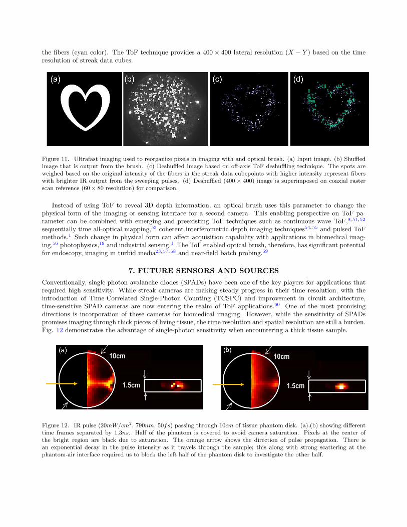
the fibers (cyan color). The ToF technique provides a 400 ⇥ 400 lateral resolution (X � Y ) based on the timeresolution of streak data cubes.
Figure 11. Ultrafast imaging used to reorganize pixels in imaging with and optical brush. (a) Input image. (b) Shu✏edimage that is output from the brush. (c) Deshu✏ed image based on o↵-axis ToF deshu✏ing technique. The spots areweighed based on the original intensity of the fibers in the streak data cubepoints with higher intensity represent fiberswith brighter IR output from the sweeping pulses. (d) Deshu✏ed (400 ⇥ 400) image is superimposed on coaxial rasterscan reference (60⇥ 80 resolution) for comparison.
Instead of using ToF to reveal 3D depth information, an optical brush uses this parameter to change thephysical form of the imaging or sensing interface for a second camera. This enabling perspective on ToF pa-rameter can be combined with emerging and preexisting ToF techniques such as continuous wave ToF,9,51,52
sequentially time all-optical mapping,53 coherent interferometric depth imaging techniques54,55 and pulsed ToFmethods.1 Such change in physical form can a↵ect acquisition capability with applications in biomedical imag-ing,56 photophysics,19 and industrial sensing.1 The ToF enabled optical brush, therefore, has significant potentialfor endoscopy, imaging in turbid media23,57,58 and near-field batch probing.59
7. FUTURE SENSORS AND SOURCES
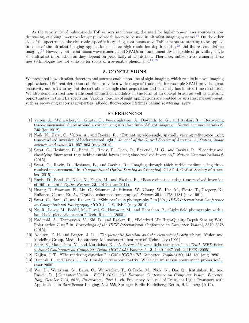
Conventionally, single-photon avalanche diodes (SPADs) have been one of the key players for applications thatrequired high sensitivity. While streak cameras are making steady progress in their time resolution, with theintroduction of Time-Correlated Single-Photon Counting (TCSPC) and improvement in circuit architecture,time-sensitive SPAD cameras are now entering the realm of ToF applications.60 One of the most promisingdirections is incorporation of these cameras for biomedical imaging. However, while the sensitivity of SPADspromises imaging through thick pieces of living tissue, the time resolution and spatial resolution are still a burden.Fig. 12 demonstrates the advantage of single-photon sensitivity when encountering a thick tissue sample.
Figure 12. IR pulse (20mW/cm2, 790nm, 50fs) passing through 10cm of tissue phantom disk. (a),(b) showing di↵erenttime frames separated by 1.3ns. Half of the phantom is covered to avoid camera saturation. Pixels at the center ofthe bright region are black due to saturation. The orange arrow shows the direction of pulse propagation. There isan exponential decay in the pulse intensity as it travels through the sample; this along with strong scattering at thephantom-air interface required us to block the left half of the phantom disk to investigate the other half.
As the sensitivity of pulsed-mode ToF sensors is increasing, the need for higher power laser sources is nowdecreasing, enabling lower cost longer pulse width lasers to be used in ultrafast imaging systems.61 On the otherside of the spectrum as the electronics speed is increasing, continuous wave ToF cameras are starting to be appliedin some of the ultrafast imaging applications such as high resolution depth sensing62 and fluorescent lifetimeimaging.51 However, both continuous wave cameras and SPADs are fundamentally incapable of providing singleshot ultrafast information as they depend on periodicity of acquisition. Therefore, unlike streak cameras thesenew technologies are not suitable for study of irreversible phenomena.18,19
8. CONCLUSIONS
We presented how ultrafast detectors and sources enable non-line of sight imaging, which results in novel imagingapplications. Di↵erent detection solutions provide a wide range of trade-o↵s, for example SPAD provides greatsensitivity and a 2D array but doesn’t allow a single shot acquisition and currently has limited time resolution.We also demonstrated non-traditional acquisition modality in the form of an optical brush as well as emergingopportunities in the THz spectrum. Various non-line of sight applications are enabled by ultrafast measurement,such as recovering material properties (albedo, fluorescence lifetime) behind scattering layers.
REFERENCES
[1] Velten, A., Willwacher, T., Gupta, O., Veeraraghavan, A., Bawendi, M. G., and Raskar, R., “Recoveringthree-dimensional shape around a corner using ultrafast time-of-flight imaging,” Nature communications 3,745 (jan 2012).
[2] Naik, N., Barsi, C., Velten, A., and Raskar, R., “Estimating wide-angle, spatially varying reflectance usingtime-resolved inversion of backscattered light,” Journal of the Optical Society of America. A, Optics, imagescience, and vision 31, 957–963 (may 2014).
[3] Satat, G., Heshmat, B., Barsi, C., Raviv, D., Chen, O., Bawendi, M. G., and Raskar, R., “Locating andclassifying fluorescent tags behind turbid layers using time-resolved inversion,” Nature Communications 6(2015).
[4] Satat, G., Raviv, D., Heshmat, B., and Raskar, R., “Imaging through thick turbid medium using time-resolved measurement,” in [Computational Optical Sensing and Imaging ], CT3F–4, Optical Society of Amer-ica (2015).
[5] Raviv, D., Barsi, C., Naik, N., Feigin, M., and Raskar, R., “Pose estimation using time-resolved inversionof di↵use light,” Optics Express 22, 20164 (aug 2014).
[6] Huang, D., Swanson, E., Lin, C., Schuman, J., Stinson, W., Chang, W., Hee, M., Flotte, T., Gregory, K.,Puliafito, C., and Et, A., “Optical coherence tomography,” Science 254, 1178–1181 (nov 1991).
[7] Satat, G., Barsi, C., and Raskar, R., “Skin perfusion photography,” in [2014 IEEE International Conferenceon Computational Photography (ICCP) ], 1–8, IEEE (may 2014).
[8] Ng, R., Levoy, M., Bredif, M., Duval, G., Horowitz, M., and Hanrahan, P., “Light field photography with ahand-held plenoptic camera,” Tech. Rep. 11 (2005).
[9] Kadambi, A., Taamazyan, V., Shi, B., and Raskar, R., “Polarized 3D: High-Quality Depth Sensing WithPolarization Cues,” in [Proceedings of the IEEE International Conference on Computer Vision ], 3370–3378(2015).
[10] Adelson, E. H. and Bergen, J. R., [The plenoptic function and the elements of early vision ], Vision andModeling Group, Media Laboratory, Massachusetts Institute of Technology (1991).
[11] Seitz, S., Matsushita, Y., and Kutulakos, K., “A theory of inverse light transport,” in [Tenth IEEE Inter-national Conference on Computer Vision (ICCV’05) Volume 1 ], 2, 1440–1447 Vol. 2, IEEE (2005).
[12] Kajiya, J. T., “The rendering equation,” ACM SIGGRAPH Computer Graphics 20, 143–150 (aug 1986).[13] Ramesh, R. and Davis, J., “5d time-light transport matrix: What can we reason about scene properties?,”
(mar 2008).[14] Wu, D., Wetzstein, G., Barsi, C., Willwacher, T., O’Toole, M., Naik, N., Dai, Q., Kutulakos, K., and
Raskar, R., [Computer Vision – ECCV 2012: 12th European Conference on Computer Vision, Florence,Italy, October 7-13, 2012, Proceedings, Part I ], ch. Frequency Analysis of Transient Light Transport withApplications in Bare Sensor Imaging, 542–555, Springer Berlin Heidelberg, Berlin, Heidelberg (2012).

[15] Ranka, J. K., Gaeta, A. L., Baltuska, A., Pshenichnikov, M. S., and Wiersma, D. A., “Autocorrelationmeasurement of 6-fs pulses based on the two-photon-induced photocurrent in a GaAsP photodiode,” OpticsLetters 22, 1344 (sep 1997).
[16] Heshmat, B., Pahlevaninezhad, H., and Darcie, T., “E�cient low-power autocorrelation measurement withcarbon nanotube photoconductors,” in [Conference on Lasers and Electro-Optics 2012 ], JW2A.3, OSA,Washington, D.C. (may 2012).
[17] Nabekawa, Y., Shimizu, T., Okino, T., Furusawa, K., Hasegawa, H., Yamanouchi, K., and Midorikawa, K.,“Interferometric autocorrelation of an attosecond pulse train in the single-cycle regime.,” Physical reviewletters 97, 153904 (oct 2006).
[18] Heshmat, B., Satat, G., Barsi, C., and Raskar, R., “Single-shot ultrafast imaging using parallax-free align-ment with a tilted lenslet array,” Cleo: 2014 1(1), STu3E.7 (2014).
[19] Gao, L., Liang, J., Li, C., and Wang, L. V., “Single-shot compressed ultrafast photography at one hundredbillion frames per second,” Nature 516, 74–77 (dec 2014).
[20] Velten, A., Raskar, R., Wu, D., Jarabo, A., Masia, B., Barsi, C., Joshi, C., Lawson, E., Bawendi, M., andGutierrez, D., “Femto-photography,” ACM Transactions on Graphics 32, 1 (jul 2013).
[21] Sen, P., Chen, B., Garg, G., Marschner, S. R., Horowitz, M., Levoy, M., and Lensch, H. P. A., “Dualphotography,” ACM Transactions on Graphics 24, 745–755 (jul 2005).
[22] Ariese, F., Meuzelaar, H., Kerssens, M. M., Buijs, J. B., and Gooijer, C., “Picosecond Raman spectroscopywith a fast intensified CCD camera for depth analysis of di↵usely scattering media.,” The Analyst 134,1192–7 (jun 2009).
[23] Wu, J., Wang, Y., Perelman, L., Itzkan, I., Dasari, R. R., and Feld, M. S., “Three-dimensional imaging ofobjects embedded in turbid media with fluorescence and Raman spectroscopy.,” Applied optics 34, 3425–30(jun 1995).
[24] Takahashi, E., Kato, S., Furutani, H., Sasaki, A., Kishimoto, Y., Takada, K., Matsumura, S., and Sasaki,H., “Single-shot observation of growing streamers using an ultrafast camera,” Journal of Physics D: AppliedPhysics 44, 302001 (aug 2011).
[25] Heshmat, B., Pahlevaninezhad, H., and Darcie, T. E., “Carbon Nanotube-Based Photoconductive Switchesfor THz Detection: An Assessment of Capabilities and Limitations,” IEEE Photonics Journal 4, 970–985(jun 2012).
[26] Ibrahim, A., Ferachou, D., Sharma, G., Singh, K., Kirouac-Turmel, M., and Ozaki, T., “Ultra-high dynamicrange electro-optic sampling for detecting millimeter and sub-millimeter radiation,” Scientific Reports 6,23107 (mar 2016).
[27] Heshmat, B., Masnadi-Shirazi, M., Lewis, R. B., Zhang, J., Tiedje, T., Gordon, R., and Darcie, T. E.,“Enhanced Terahertz Bandwidth and Power from GaAsBi-based Sources,” Advanced Optical Materials 1,714–719 (oct 2013).
[28] Gupta, O., Willwacher, T., Velten, A., Veeraraghavan, A., and Raskar, R., “Reconstruction of hidden 3Dshapes using di↵use reflections.,” Optics express 20, 19096–108 (aug 2012).
[29] Naik, N., Multibounce light transport analysis using ultrafast imaging for material acquisition, PhD thesis,Massachusetts Institute of Technology (2012).
[30] Naik, N., Zhao, S., Velten, A., Raskar, R., and Bala, K., “Single view reflectance capture using multiplexedscattering and time-of-flight imaging,” in [ACM Transactions on Graphics (TOG) ], 30(6), 171, ACM (2011).
[31] Weyrich, T., Lawrence, J., Lensch, H., Rusinkiewicz, S., and Zickler, T., “Principles of appearance ac-quisition and representation,” Foundations and Trends R� in Computer Graphics and Vision 4(2), 75–191(2009).
[32] Lichtman, J. W. and Conchello, J.-A., “Fluorescence microscopy,” Nature methods 2, 910–919 (dec 2005).[33] Williams, Jr., G. M., Allen, T., Dupuy, C., Novet, T., and Schut, D., “Optically coded nanocrystal taggants
and optical frequency IDs,” in [SPIE Defense, Security, and Sensing ], 76730M, International Society forOptics and Photonics (apr 2010).
[34] Lackowicz, J. R., [Principles of Fluorescence Spectroscopy ], Springer (2006).[35] Redford, G. I., Majumdar, Z. K., Sutin, J. D. B., and Clegg, R. M., “Properties of microfluidic turbulent
mixing revealed by fluorescence lifetime imaging,” The Journal of chemical physics 123, 224504 (dec 2005).

[36] Koenig, K., Wollina, U., Riemann, I., Peukert, C., Halbhuber, K.-J., Konrad, H., Fischer, P., Fuenfstueck,V., Fischer, T. W., and Elsner, P., “Optical tomography of human skin with subcellular spatial and picosec-ond time resolution using intense near infrared femtosecond laser pulses,” in [International Symposium onBiomedical Optics ], 191–201, International Society for Optics and Photonics (jun 2002).
[37] Satat, G., Barsi, C., Heshmat, B., Raviv, D., and Raskar, R., “Locating fluorescence lifetimes behindturbid layers non-invasively using sparse, time-resolved inversion,” in [CLEO: QELS Fundamental Science ],JTh2A–43, Optical Society of America (2014).
[38] Satat, G., Imaging through scattering, PhD thesis, Massachusetts Institute of Technology (2015).[39] Pati, Y., Rezaiifar, R., and Krishnaprasad, P., “Orthogonal matching pursuit: recursive function approxima-
tion with applications to wavelet decomposition,” in [Proceedings of 27th Asilomar Conference on Signals,Systems and Computers ], 40–44, IEEE Comput. Soc. Press (1993).
[40] Tonouchi, M., “Cutting-edge terahertz technology,” Nat. Photonics. 1(2), 97–105 (2007).[41] Siegel, P. H., “Terahertz technology,” IEEE Trans. Microw. Theory Techn. 50, 910–928 (Mar. 2002).[42] Jansen, C., Wietzke, S., Peters, O., Scheller, M., Vieweg, N., Salih, M., Krumbholz, N., Joerdens, C.,
Hochrein, T., and Koch, M., “Terahertz imaging: applications and perspectives,” Appl. Opt. 49(19), E48–E57 (2010).
[43] Horiuchi, N., “Terahertz technology: Endless applications,” Nat. Photonics. 4, 140–140 (Mar. 2010).[44] Jordens, C., Wietzke, S., Scheller, M., and Koch, M., “Investigation of the water absorption in polyamide
and wood plastic composite by terahertz time-domain spectroscopy,” Polym. Test. 29, 209–215 (Apr. 2010).[45] Wietzke, S., Jordens, C., Krumbholz, N., Baudrit, B., Bastian, M., and Koch, M., “Terahertz imaging: a
new non-destructive technique for the quality control of plastic weld joints,” J. Eur. Opt. Soc. Rapid 2 (Apr.2007).
[46] Jackson, B., Bowen, J. W., and Walker, G. C., “A survey of terahertz applications in cultural heritageconservation science,” IEEE Trans. THz Sci. Technol. 1, 220–231 (Sept. 2011).
[47] Fukunaga, K. and Hosako, I., “Innovative non-invasive analysis techniques for cultural heritage using tera-hertz technology,” C. R. Phys. 11, 519–526 (Aug. 2010).
[48] Manceau, J.-M., Nevin, A., Fotakis, C., and Tzortzakis, S., “Terahertz time domain spectroscopy for theanalysis of cultural heritage related materials,” Appl. Phys. B 90, 365–368 (Mar. 2008).
[49] Seco-Martorell, C., Lopez-Domınguez, V., Arauz-Garofalo, G., Redo-Sanchez, A., and Tejada, J., “Goya’sartwork imaging with Terahertz waves,” Opt. Express 21, 17800–17805 (July 2013).
[50] Heshmat, B., Lee, I. H., and Raskar, R., “Optical brush: Imaging through permuted probes,” ScientificReports 6, 20217 (feb 2016).
[51] Bhandari, A., Barsi, C., and Raskar, R., “Blind and reference-free fluorescence lifetime estimation viaconsumer time-of-flight sensors,” Optica 2, 965 (nov 2015).
[52] Naik, N., Kadambi, A., Rhemann, C., Izadi, S., Raskar, R., and Bing Kang, S., “A light transport modelfor mitigating multipath interference in time-of-flight sensors,” 73–81 (2015).
[53] Nakagawa, K., Iwasaki, A., Oishi, Y., Horisaki, R., Tsukamoto, A., Nakamura, A., Hirosawa, K., Liao, H.,Ushida, T., Goda, K., Kannari, F., and Sakuma, I., “Sequentially timed all-optical mapping photography(STAMP),” Nature Photonics 8, 695–700 (aug 2014).
[54] Cizmar, T. and Dholakia, K., “Exploiting multimode waveguides for pure fibre-based imaging.,” Naturecommunications 3, 1027 (jan 2012).
[55] Adler, D. C., Chen, Y., Huber, R., Schmitt, J., Connolly, J., and Fujimoto, J. G., “Three-dimensionalendomicroscopy using optical coherence tomography,” Nature Photonics 1, 709–716 (nov 2007).
[56] Goda, K., Tsia, K. K., and Jalali, B., “Serial time-encoded amplified imaging for real-time observation offast dynamic phenomena.,” Nature 458, 1145–9 (apr 2009).
[57] Patwardhan, S. V. and Culver, J. P., “Quantitative di↵use optical tomography for small animals using anultrafast gated image intensifier,” Journal of biomedical optics 13(1), 011009–011009 (2008).
[58] Flusberg, B. A., Cocker, E. D., Piyawattanametha, W., Jung, J. C., Cheung, E. L. M., and Schnitzer, M. J.,“Fiber-optic fluorescence imaging.,” Nature methods 2, 941–950 (2005).
[59] Chibani, H., Dukenbayev, K., Mensi, M., Sekatskii, S. K., and Dietler, G., “Near-field scanning opticalmicroscopy using polymethylmethacrylate optical fiber probes.,” Ultramicroscopy 110, 211–5 (feb 2010).

[60] Gariepy, G., Krstajic, N., Henderson, R., Li, C., Thomson, R. R., Buller, G. S., Heshmat, B., Raskar, R.,Leach, J., and Faccio, D., “Single-photon sensitive light-in-fight imaging.,” Nature communications 6, 6021(jan 2015).
[61] Squier, J. and Muller, M., “High resolution nonlinear microscopy: A review of sources and methods forachieving optimal imaging,” Review of Scientific Instruments 72, 2855 (jul 2001).
[62] Kadambi, A., Whyte, R., Bhandari, A., Streeter, L., Barsi, C., Dorrington, A., and Raskar, R., “Codedtime of flight cameras,” ACM Transactions on Graphics 32, 1–10 (nov 2013).
View publication statsView publication stats