advances in the analysis of dioxin and environmental toxicants
TRANSCRIPT

Advances in the Analysis of Dioxin and Environmental Toxicants

2 2
Co-Authors
Eric Reiner, Terry Kolic, Karen MacPherson, Sheng Yang, Alina Muscalu, Adrienne Boden,
Karl Jobst, Patrick Crozier, Vin Khurana, Teresa Gobran, Liad Haimovici, , Li Shen
Christy Hartley, Rob Brunato, Vince Taguchi, Jeff Scott, Paul Helm, Tony Chen,
Vadrana Pantelic, Gerry Ladwig
Frank Dorman, Jack Cochran,
Peter Gorst-AllmanJoe Binkley, David E Alonso
Ian Brindle, Chris Marvin

3 3
What is Dioxin?
Polychlorinated dibenzo-p-dioxins (PCDD) and polychlorinated furans (PCDFs) • A group of 210 compounds with chlorines 0 to 8 chlorines
2,3,7,8-tetrachlorodibenzo-p-dioxin 2,3,7,8-tetrachlorodibenzofuran

44
What is Dioxin?
• Most toxic group of chemicals with LD50 as low as 1 ug/kg body weight
• Persistent, bioacummulative and toxic
• Health effects include: immune impairment, reproductive disorders, weight loss, development impairment, cancer
• Toxicity through the AhR binding
LD50: Lethal dose (50% test population)

5

6 6
NOEL = 3g/kg LD50 = 1ug/kg
TCDD: 2,3,7,8-tetrachlorodibenzo-p-dioxin NOEL: No-observable effect-level LD50: Lethal dose (50% test population)
Dioxin Toxicity

7
8
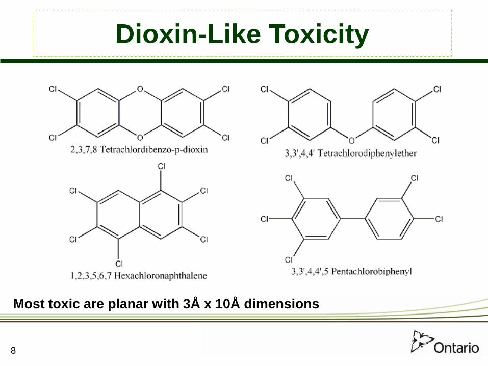
Most toxic are planar with 3Å x 10Å dimensions
Dioxin-Like Toxicity

9

Toxic Equivalent Quantity (TEQ)
• Results reported in TEQ normalized to 2,3,7,8-TCDD
• TEQ = Σ[PCDDi×TEFi] + Σ[PCDFj×TEFj] + Σ[PCBk×TEFk] + Σ[DLCl×TEFl]
Where: i = 1−7, j = 1−10, k = 1−12, l = 1−?
10

Dioxin/PCB TEFs Eadon Ontario Germany California USEPA Nordic NATO-I WHO WHO WHO 1982 1984 1985 1986 1987 1988 1989 1994 1998 2005
PCDDs 2,3,7,8-TCDD 1 1 1 1 1 1 1 1 1 1,2,3,7,8-PeCDD 1 0.1 0.1 1 0.5 0.5 0.5 1 1 1,2,3,4,7,8-HxCDD 0.03 0.1 0.1 0.03 0.04 0.1 0.1 0.1 0.1 1,2,3,6,7,8-HxCDD 0.03 0.1 0.1 0.03 0.04 0.1 0.1 0.1 0.1 1,2,3,7,8,9-HxCDD 0.03 0.1 0.1 0.03 0.04 0.1 0.1 0.1 0.1 1,2,3,4,6,7,8-HpCDD 0 0.01 0.01 0.03 0.001 0.01 0.01 0.01 0.01
1,2,3,4,6,7,8,9-OCDD 0 0.0001 0.001 0 0 0.001 0.001 0.0001 0.0003
PCDFs 2,3,7,8-TCDF 0.33 0.5 0.1 1 0.1 0.1 0.1 0.1 0.1 1,2,3,7,8-PeCDF 0.33 0.5 0.1 1 0.1 0.01 0.05 0.05 0.03 2,3,4,7,8-PeCDF 0.33 0.5 0.1 1 0.1 0.5 0.5 0.5 0.3 1,2,3,4,7,8-HxCDF 0.01 0.1 0.01 0.03 0.01 0.1 0.1 0.1 0.1 1,2,3,6,7,8-HxCDF 0.01 0.1 0.01 0.03 0.01 0.1 0.1 0.1 0.1 1,2,3,7,8,9-HxCDF 0.01 0.1 0.01 0.03 0.01 0.1 0.1 0.1 0.1 2,3,4,6,7,8-HxCDF 0.01 0.1 0.01 0.03 0.01 0.1 0.1 0.1 0.1 1,2,3,4,6,7,8-HpCDF 0 0.01 0.01 0.03 0.001 0.01 0.01 0.01 0.01 1,2,3,4,7,8,9-HpCDF 0 0.01 0.01 0.03 0.001 0.01 0.01 0.01 0.01 1,2,3,4,6,7,8,9-OCDF 0 0.0001 0 0 0 0.001 0.001 0.0001 0.0003
dl-PCBs PCB-077 (3,3',4,4'-TCB) 0.0005 0.0001 0.0001
PCB-081 (3,4,4',5-TCB) 0 0.0001 0.0003
PCB-105 (2,3,3',4,4'-PeCB) 0.0001 0.0001 0.00003
PCB-114 (2,3,4,4',5-PeCB) 0.0005 0.0005 0.00003
PCB-118 (2,3',4,4',5-PeCB) 0.0001 0.0001 0.00003
PCB-123 (2',3,4,4',5-PeCB) 0.0001 0.0001 0.00003
PCB-126 (3,3',4,4',5-PeCB) 0.1 0.1 0.1
PCB-156 (2,3,3',4,4',5-HxCB) 0.0005 0.0005 0.00003
PCB-157 (2,3,3',4,4',5'-HxCB) 0.0005 0.0005 0.00003
PCB-167 (2,3',4,4',5,5'-HxCB) 0.00001 0.00001 0.00003
PCB-169 (3,3',4,4',5,5'-HxCB) 0.01 0.01 0.03
PCB-189 (2,3,3',4,4',5,5'-HpCB) 0.0001 0.0001 0.00003
11

Agent Orange
3× > miscarriagesin sprayed areas
12

Seveso, Italy – 1976
Chlorophenol plant explosion
•Normal sex ratio 106 males to 100 females• Seveso parents produced only 26 boys to 48 girls
Mocarelli et al, Lancet, 1996
13

Yuschenko Poisoning – 2002
14

Yuschenko Poisoning – 2009
15

16 16
Dioxin Sources
• Open burning/wood burning• Medical and waste incineration • Chemical fires• Auto exhaust• Chemical production• Tanneries• Metal reclamation• Industrial emissions

Pulp and paper plant lagoon 17

Open Barrel Burning
18

Hagarsville Tire Fire – 1990
19

Hagarsville Tire Fire – 1990
20

212121
Plastimet Recycling Plant Fire – 1997
21

22 22
POPs Food Contamination
• BB-153 FeedMaster/FireMaster• Belgian dairy – Dioxin/PCBs1999• Irish Chicken – Dioxin 2006• German chicken – Dioxin 2009
BB = Brominated Biphenyl
23 23
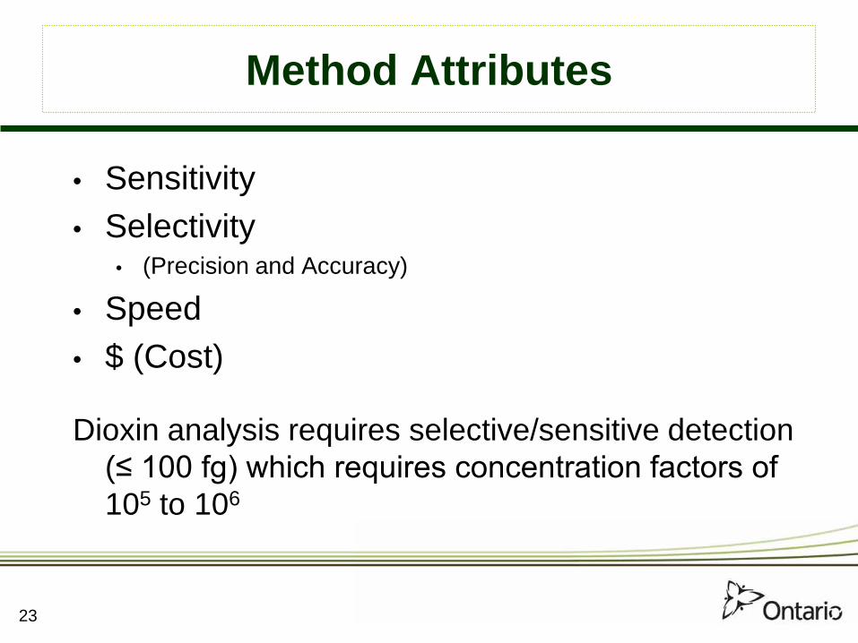
Method Attributes
• Sensitivity • Selectivity
• (Precision and Accuracy)
• Speed • $ (Cost)
Dioxin analysis requires selective/sensitive detection (≤ 100 fg) which requires concentration factors of 105 to 106
24 24
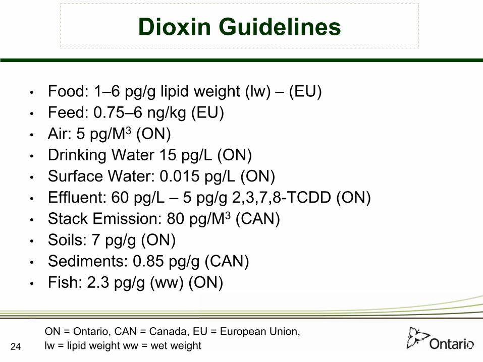
Dioxin Guidelines
• Food: 1–6 pg/g lipid weight (lw) – (EU)• Feed: 0.75–6 ng/kg (EU)• Air: 5 pg/M3 (ON)• Drinking Water 15 pg/L (ON)• Surface Water: 0.015 pg/L (ON)• Effluent: 60 pg/L – 5 pg/g 2,3,7,8-TCDD (ON)• Stack Emission: 80 pg/M3 (CAN)• Soils: 7 pg/g (ON)• Sediments: 0.85 pg/g (CAN)• Fish: 2.3 pg/g (ww) (ON)
ON = Ontario, CAN = Canada, EU = European Union, lw = lipid weight ww = wet weight

25 25
Dioxin Daily Intake Guidelines
• Average Daily intake: 1 to 3 pg/kg/day
Guidelines:U.S. EPA: 0.7 pg/kg/dayEU: 1–4 pg/kg/dayCanada: 10 pg/kg/day
26 26
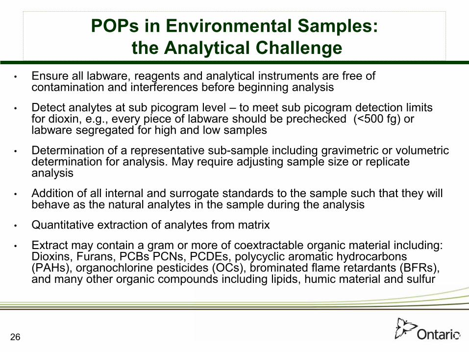
POPs in Environmental Samples:the Analytical Challenge
• Ensure all labware, reagents and analytical instruments are free of contamination and interferences before beginning analysis
• Detect analytes at sub picogram level – to meet sub picogram detection limits for dioxin, e.g., every piece of labware should be prechecked (<500 fg) or labware segregated for high and low samples
• Determination of a representative sub-sample including gravimetric or volumetric determination for analysis. May require adjusting sample size or replicate analysis
• Addition of all internal and surrogate standards to the sample such that they will behave as the natural analytes in the sample during the analysis
• Quantitative extraction of analytes from matrix
• Extract may contain a gram or more of coextractable organic material including: Dioxins, Furans, PCBs PCNs, PCDEs, polycyclic aromatic hydrocarbons (PAHs), organochlorine pesticides (OCs), brominated flame retardants (BFRs), and many other organic compounds including lipids, humic material and sulfur
27 27
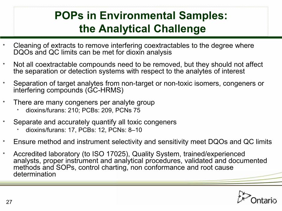
POPs in Environmental Samples:the Analytical Challenge
* Cleaning of extracts to remove interfering coextractables to the degree where DQOs and QC limits can be met for dioxin analysis
* Not all coextractable compounds need to be removed, but they should not affect the separation or detection systems with respect to the analytes of interest
* Separation of target analytes from non-target or non-toxic isomers, congeners or interfering compounds (GC-HRMS)
* There are many congeners per analyte group* dioxins/furans: 210; PCBs: 209, PCNs 75
* Separate and accurately quantify all toxic congeners* dioxins/furans: 17, PCBs: 12, PCNs: 8–10
* Ensure method and instrument selectivity and sensitivity meet DQOs and QC limits
* Accredited laboratory (to ISO 17025), Quality System, trained/experienced analysts, proper instrument and analytical procedures, validated and documented methods and SOPs, control charting, non conformance and root cause determination

28 28
POPs in Environmental Samples:the Analytical Challenge
* Ensure quantitative accuracy* Calibration, blanks, spiked samples, CRMs, ILS, Performance Evaluation, surrogates and
internal standards, standard validation.
* Other Considerations:* Toxicity of compounds can range up to 6 orders of magnitude* T4CDD toxicity can range from: NOEL = 3 g/kg to LD50 = 1 ug/kg – must identify correct isomers
using proper GC columns and conditions.* Range of concentrations – fg/g (10-15 g/g ) to % levels – potential lab contamination and
instrument issues from carryover.* Range of sample types and complexities – biota, air, water, soil, hazardous waste which have
different matrix dependent and method requirement issues. Use method fit for purpose that has been validated for specific matrix being analyzed.
* Are the patterns of congeners representative of samples being analyzed, e.g., does an ash sample have a combustion source pattern or does a biota sample have only the toxic congeners present?

Analytical Approach
• Selection of appropriate method • Fit for Purpose
• Quantitative extraction of analytes from matrix • Cleanup of sample extract to remove
interfering matrix and coextractable compounds
• Chromatographic separation – selective detection
29
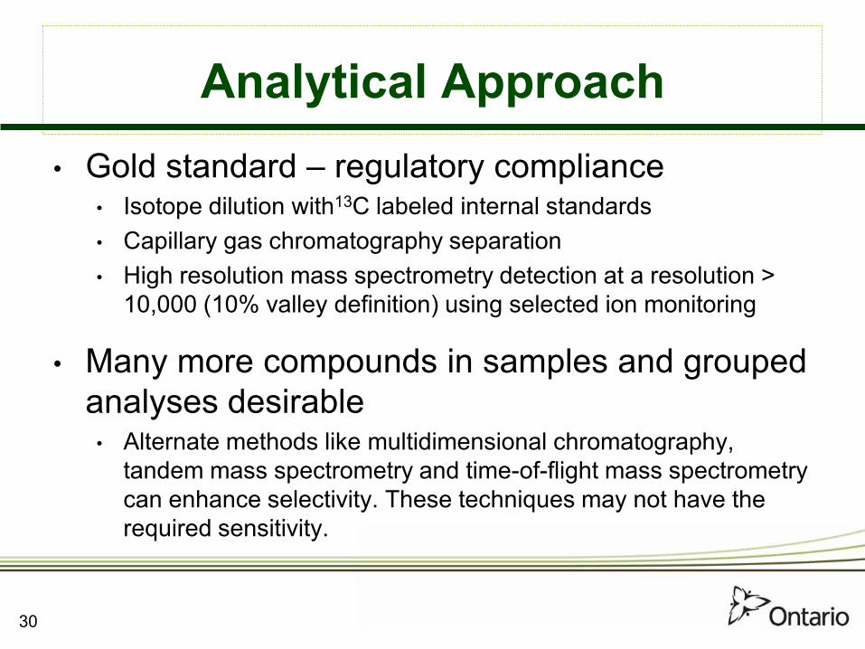
Analytical Approach• Gold standard – regulatory compliance
• Isotope dilution with13C labeled internal standards• Capillary gas chromatography separation• High resolution mass spectrometry detection at a resolution >
10,000 (10% valley definition) using selected ion monitoring
• Many more compounds in samples and grouped analyses desirable• Alternate methods like multidimensional chromatography,
tandem mass spectrometry and time-of-flight mass spectrometry can enhance selectivity. These techniques may not have the required sensitivity.
30

Horwitz Uncertainty Curve
from Eppe, Chemosphere 71 379, (2008) 31

32 32 32
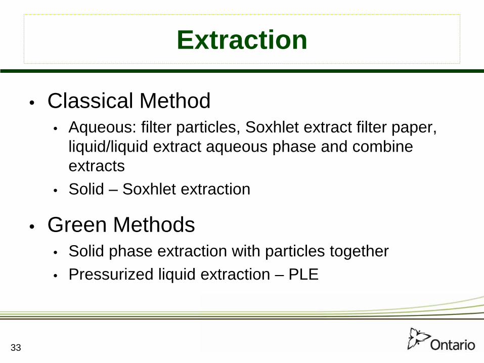
Extraction
• Classical Method • Aqueous: filter particles, Soxhlet extract filter paper,
liquid/liquid extract aqueous phase and combine extracts
• Solid – Soxhlet extraction
• Green Methods • Solid phase extraction with particles together • Pressurized liquid extraction – PLE
33

Solid Phase Extraction
34

Solid Phase Extraction
35

d Phase Extraction

Solid Phase Extraction
37

Pressurized Liquid Extraction – PLE
38
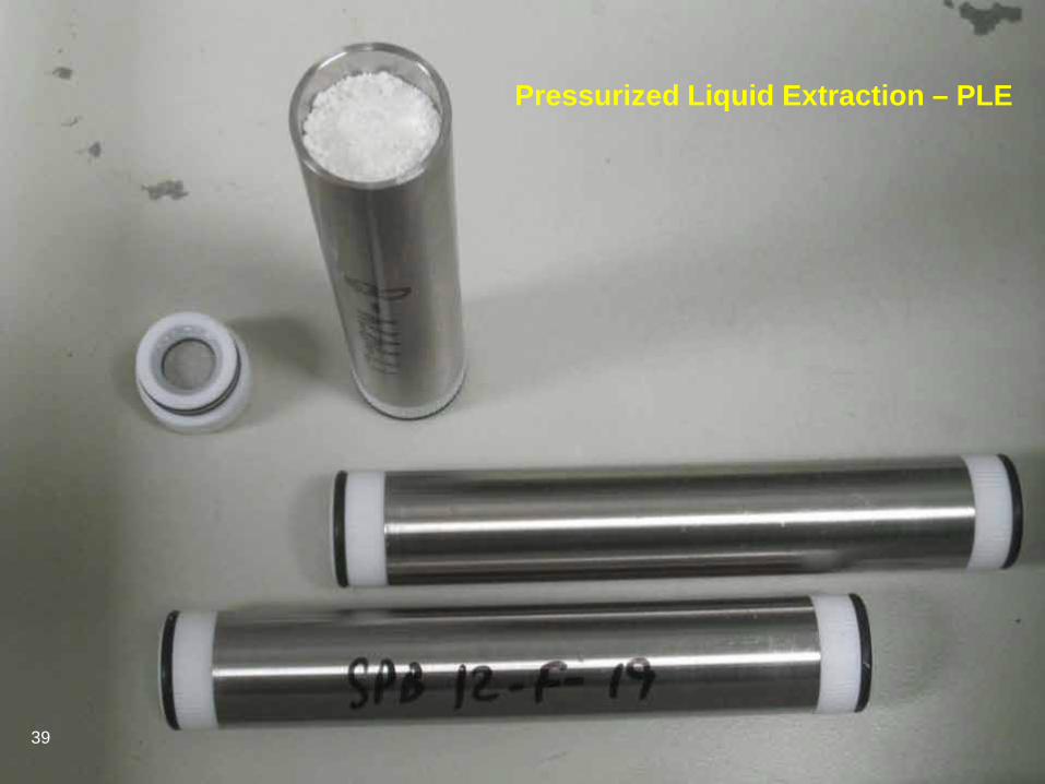
Pressurized Liquid Extraction – PLE
39
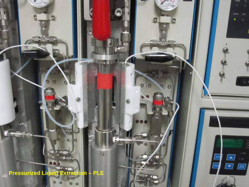
Pressurized Liquid Extraction – PLE 40
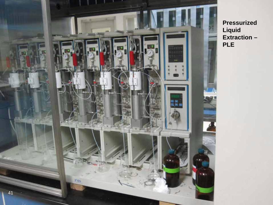
Pressurized Liquid Extraction – PLE
41
42 4242
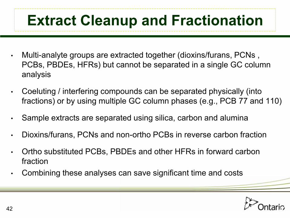
Extract Cleanup and Fractionation
• Multi-analyte groups are extracted together (dioxins/furans, PCNs , PCBs, PBDEs, HFRs) but cannot be separated in a single GC column analysis
• Coeluting / interfering compounds can be separated physically (into fractions) or by using multiple GC column phases (e.g., PCB 77 and 110)
• Sample extracts are separated using silica, carbon and alumina
• Dioxins/furans, PCNs and non-ortho PCBs in reverse carbon fraction
• Ortho substituted PCBs, PBDEs and other HFRs in forward carbon fraction
• Combining these analyses can save significant time and costs

Classical Open Column Sample Preparation
43

Classical Open Column Sample Preparation
44

FMS PowerPrep
45 FMS = fluid management systems
45

FMS PowerPrep
46

FMS – WMF-01 – 10 replicates
0
20
40
60
80
100
120
140
13C-23
78-T
CDF
13C-12
378-P
eCDF
13C-23
478-P
eCDF
13C-12
3478
-HxC
DF
13C-12
3678
-HxC
DF
13C-23
4678
-HxC
DF
13C-12
3789
-HxC
DF
13C-12
3467
8-HpC
DF
13C-12
3478
9-HpC
DF
13C-23
78-T
CDD
13C-12
378-P
eCDD
13C-12
3478
-HxC
DD
13C-12
3678
-HxC
DD
13C-12
3467
8-HpC
DD
13C-O
CDD
0
20
40
60
80
100
120
140
13C-23
78-T
CDF
13C-12
378-P
eCDF
13C-23
478-P
eCDF
13C-12
3478
-HxC
DF
13C-12
3678
-HxC
DF
13C-23
4678
-HxC
DF
13C-12
3789
-HxC
DF
13C-12
3467
8-HpC
DF
13C-12
3478
9-HpC
DF
13C-23
78-T
CDD
13C-12
378-P
eCDD
13C-12
3478
-HxC
DD
13C-12
3678
-HxC
DD
13C-12
3467
8-HpC
DD
13C-O
CDD0
20
40
60
80
100
120
140
13C-23
'4'5-te
tra pc
b (70
)
13C-34
4'5-te
tra PCB (8
1)
13C-33
'44'te
tra PCB (7
7)
13C-2'
344'5
-penta
PCB (123
)
13C-23
'44'5-
penta
PCB (118
)
13C-23
44'5-
penta
PCB (1
14)
13C-23
3'44'-
penta
PCB (105
)
13C-33
'44'5-
penta
PCB (126
)
13C-23
'44'55
'-hex
a PCB (1
67)
13C-23
3'44'5
hexa
PCB (1
56)
13C-23
3'44'5
'-hex
a PCB (1
57)
13C-33
'44'55
'-hex
a PCB (1
69)
13C-23
3'44'5
5'-he
pta P
CB (189
)
0
20
40
60
80
100
120
140
13C-23
'4'5-te
tra pc
b (70
)
13C-34
4'5-te
tra PCB (8
1)
13C-33
'44'te
tra PCB (7
7)
13C-2'
344'5
-penta
PCB (123
)
13C-23
'44'5-
penta
PCB (118
)
13C-23
44'5-
penta
PCB (1
14)
13C-23
3'44'-
penta
PCB (105
)
13C-33
'44'5-
penta
PCB (126
)
13C-23
'44'55
'-hex
a PCB (1
67)
13C-23
3'44'5
hexa
PCB (1
56)
13C-23
3'44'5
'-hex
a PCB (1
57)
13C-33
'44'55
'-hex
a PCB (1
69)
13C-23
3'44'5
5'-he
pta P
CB (189
)
020406080
100120140
13C-24
4'-tri
BDE 28
13C-22
'44'-te
tra B
DE 47
13C-22
'44'5-
penta
BDE 99
13C-22
'44'56
'-hex
a BDE 15
4
13C-22
'44'55
'-hex
a BDE 15
3
13C-22
'344'5
'6-he
pta B
DE 183
13C-de
ca BDE 20
9 0
20406080
100120140
13C-24
4'-tri
BDE 28
13C-22
'44'-te
tra B
DE 47
13C-22
'44'5-
penta
BDE 99
13C-22
'44'56
'-hex
a BDE 15
4
13C-22
'44'55
'-hex
a BDE 15
3
13C-22
'344'5
'6-he
pta B
DE 183
13C-de
ca BDE 20
9 0
20
40
60
80
100
120
140
13C-1,
3,5,7C
N-PCN(42
)
13C-1,
2,3,4C
N-PCN(27
)
13C-1,
2,3,5,
7CN-P
CN(52)
13C-1,
2,3,4,
5,7CN-P
CN(64)
13C-oc
taCN-P
CN(75)
0
20
40
60
80
100
120
140
13C-1,
3,5,7C
N-PCN(42
)
13C-1,
2,3,4C
N-PCN(27
)
13C-1,
2,3,5,
7CN-P
CN(52)
13C-1,
2,3,4,
5,7CN-P
CN(64)
13C-oc
taCN-P
CN(75)
PCDD/F DLPCB
BDEs PCNs
47 CRM = certified reference material 47
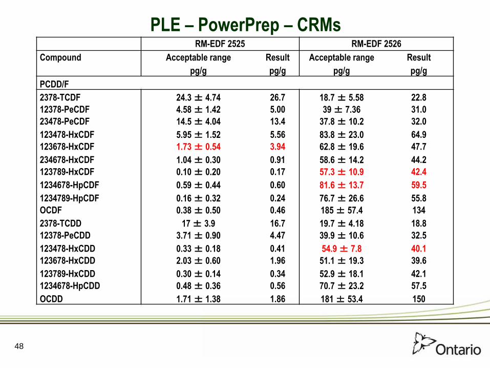
RM-EDF 2525 RM-EDF 2526 Compound Acceptable range Result Acceptable range Result pg/g pg/g pg/g pg/g PCDD/F 2378-TCDF 24.3 ± 4.74 26.7 18.7 ± 5.58 22.8 12378-PeCDF 4.58 ± 1.42 5.00 39 ± 7.36 31.0 23478-PeCDF 14.5 ± 4.04 13.4 37.8 ± 10.2 32.0 123478-HxCDF 5.95 ± 1.52 5.56 83.8 ± 23.0 64.9 123678-HxCDF 1.73 ± 0.54 3.94 62.8 ± 19.6 47.7 234678-HxCDF 1.04 ± 0.30 0.91 58.6 ± 14.2 44.2 123789-HxCDF 0.10 ± 0.20 0.17 57.3 ± 10.9 42.4 1234678-HpCDF 0.59 ± 0.44 0.60 81.6 ± 13.7 59.5 1234789-HpCDF 0.16 ± 0.32 0.24 76.7 ± 26.6 55.8 OCDF 0.38 ± 0.50 0.46 185 ± 57.4 134 2378-TCDD 17 ± 3.9 16.7 19.7 ± 4.18 18.8 12378-PeCDD 3.71 ± 0.90 4.47 39.9 ± 10.6 32.5 123478-HxCDD 0.33 ± 0.18 0.41 54.9 ± 7.8 40.1 123678-HxCDD 2.03 ± 0.60 1.96 51.1 ± 19.3 39.6 123789-HxCDD 0.30 ± 0.14 0.34 52.9 ± 18.1 42.1 1234678-HpCDD 0.48 ± 0.36 0.56 70.7 ± 23.2 57.5 OCDD 1.71 ± 1.38 1.86 181 ± 53.4 150
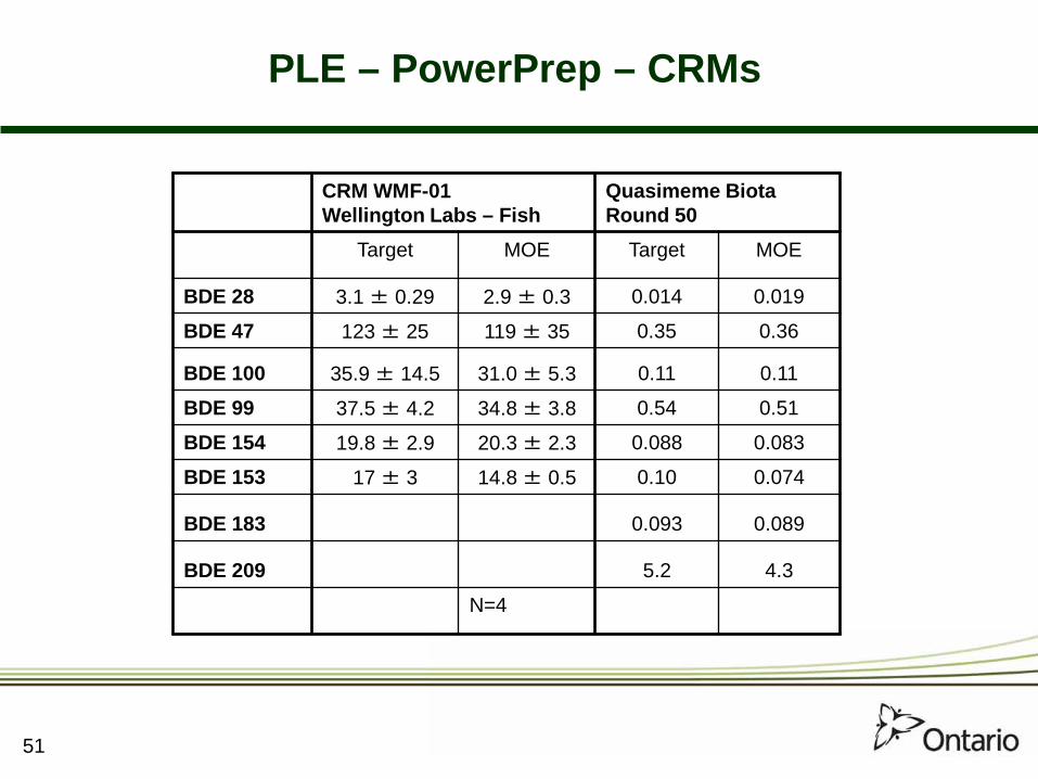
PLE – PowerPrep – CRMs
48

RM-EDF 2525 RM-EDF 2526 Compound Acceptable range Result Acceptable range Result pg/g pg/g pg/g pg/g DLPCBs 344'5-tetra PCB (81) 161 ± 74.0 199 3.0 ± 5.60 2.5 33'44'-tetra PCB (77) 1850 ± 834 2040 451 ± 179 546 2'344'5-penta PCB (123) 3280 ± 2020 6670 7.38 ± 9.58 25.6 23'44'5-penta PCB (118) 122000 ± 38000 122000 348 ± 392 468 2344'5-penta PCB (114) 3410 ± 1550 3890 7.73 ± 4.36 13.7 233'44'-penta PCB (105) 50100 ± 15700 5600 108 ± 73 178 33'44'5-penta PCB (126) 628 ± 242 654 431 ± 17.9 522 23'44'55'-hexa PCB (167) 7060 ± 3020 8070 12 ± 9.54 21.4 233'44'5-hexa PCB (156) 13100 ± 2620 14000 23.3 ± 23.8 34.2 233'44'5'-hexa PCB (157) 3380 ± 1010 3670 9.3 ± 9.16 12.1 33'44'55'-hexa PCB (169) 52.1 ± 14.0 53.8 512 ± 160 592 233'44'55'-hepta PCB (189) 1440 ± 498 1586 3.51 ± 2.76 5.1
PLE – PowerPrep – CRMs
49

RM-EDF 2525
Compound Acceptable range Result pg/g pg/g
BDEs 244'-tri BDE 28 312 ± 202 330 22'45'-tetra BDE 49 524 ± 274 550 22'44'-tetra BDE 47 9080 ± 2620 9610 23'44'-tetra BDE 66 262 ± 81.0 336 22'44'6-penta BDE 100 1720 ± 566 1540 22'44'5-penta BDE 99 2280 ± 472 2490 22'44'56'-hexa BDE 154 2550 ± 1000 2930 22'44'55'-hexa BDE 153 2030 ± 506 2040 22'344'5'6-hepta BDE 183 137± 47.8 133 Deca BDE 209 545 ± 1999 2440
PLE – PowerPrep – CRMs
50
51
CRM WMF-01 Wellington Labs – Fish
Quasimeme Biota Round 50
Target MOE Target MOE
BDE 28 3.1 ± 0.29 2.9 ± 0.3 0.014 0.019
BDE 47 123 ± 25 119 ± 35 0.35 0.36
BDE 100 35.9 ± 14.5 31.0 ± 5.3 0.11 0.11
BDE 99 37.5 ± 4.2 34.8 ± 3.8 0.54 0.51
BDE 154 19.8 ± 2.9 20.3 ± 2.3 0.088 0.083
BDE 153 17 ± 3 14.8 ± 0.5 0.10 0.074
BDE 183 0.093 0.089
BDE 209 5.2 4.3
N=4
PLE – PowerPrep – CRMs

Method
Solvent Usage (mL)
Time (days)*
Wages
Cost ($CDN)
Solvent
Column Packing
Total
Extraction Acid digestion 3620 2 40.00 18.40 10.77 29.17
ASE 960 1 20.00 4.04 3.83 7.87
Sample Cleanup Column Chromatography 7788 3 60 48.53 7.61 56.14
FMS 8176 2 40 38.30 68.85 107.15
Combined Extraction and Cleanup Acid digestion + Column Chromatography
11408
5
100
66.93
18.38
185.31
ASE + FMS 9136 3 60 42.34 72.68 175.02
Cost Comparison
52
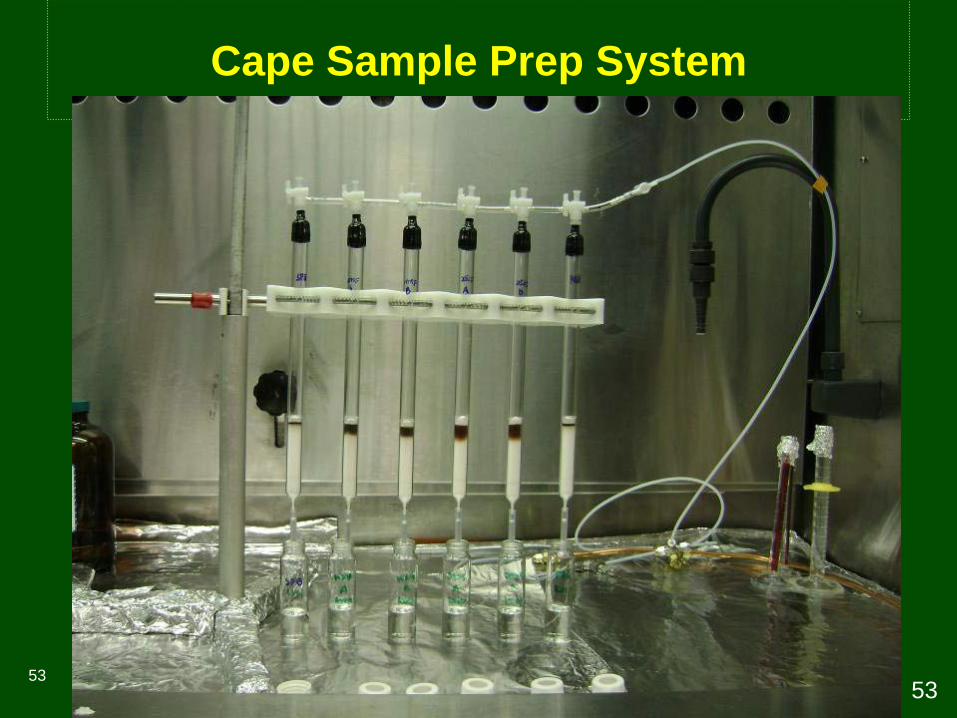
Cape Sample Prep System
53 53

Cape Technologies – Spiked Surrogates n=10
54

WMF-01-A
WMF-01-B Certified Range EDF
2525 - A EDF
2525 - B Certified Range
Dioxins 2378-TCDF 11 11 13.1 ± 4.9 25 25 24.3 ± 4.74 12378-PeCDF 1.2 <1.0 1.53 ± 1.4 4.3 4.2 4.58 ± 1.42 23478-PeCDF 4.8 5.3 7.15 ± 2.2 14 13 14.5 ± 4.04 123478-HxCDF 1.8 2.1 0.86 ± 1.0 6.0 6.7 5.95 ± 1.52 123678-HxCDF 1.4 <0.34 0.51 ± 0.7 1.2 2.0 1.73 ± 0.54 234678-HxCDF <0.75 0.67 0.68 ± 1.2 0.79 <0.69 1.04 ± 0.30 123789-HxCDF <0.59 <0.55 0.25 ± 0.4 <0.41 <0.33 0.10 ± 0.20 1234678-HpCDF <0.50 <0.30 1.01 ± 1.9 <0.37 <0.28 0.59 ± 0.44 1234789-HpCDF <0.54 <0.61 0.30 ± 0.5 <0.34 <0.29 0.16 ± 0.32 OCDF <0.43 <0.56 1.38 ± 2.1 <0.39 <0.27 0.38 ± 0.50 2378-TCDD 11 11 13.1 ± 4.4 18 18 17.0 ± 3.90 12378-PeCDD 2.0 2.2 2.72 ± 1.3 3.9 3.4 3.71 ± 0.90 123478-HxCDD <0.35 <0.40 0.22 ± 0.3 <0.35 <0.28 0.33 ± 0.18 123678-HxCDD <0.59 0.6 0.88 ± 0.4 1.8 1.6 2.03 ± 0.60 123789-HxCDD <0.46 <0.55 0.27 ± 0.4 <0.48 <0.38 0.30 ± 0.14 1234678-HpCDD <0.51 <0.73 0.59 ± 0.7 <0.37 <0.39 0.48 ± 0.36 OCDD <0.81 <0.59 3.91 ± 6.2 <1.4 <1.1 1.71 ± 1.38
Dioxin Data Comparison
55

WMF-01-A
WMF-01-B Certified Range EDF
2525 - A EDF
2525 - B Certified Range
dlPCBs
344'5-tetra PCB (81) 122 127 201 ± 58 142 131 161 ± 74.0
33'44'-tetra PCB (77) 1716 1723 2233 ± 720 1678 1888 1850 ±834
2'344'5-penta PCB (123) 3258 3459 4233 ± 2620 4193 4086 3280 ± 2020
23'44'5-penta PCB (118) 107266 107901 130100 ± 32500 103411 91634 122000 ± 38000
2344'5-penta PCB (114) 3027 3049 3523 ± 1670 3698 3517 3410 ± 1550
233'44'-penta PCB (105) 47817 46705 49050 ± 14200 56116 54329 50100 ± 15700
33'44'5-penta PCB (126) 615 618 739 ± 260 638 608 628 ± 242
23'44'55'-hexa PCB (167) 9244 9027 9750 ± 3090 7773 7479 7060 ± 3020
233'44'5-hexa PCB (156) 13906 13504 14890 ± 5020 13727 13083 13100 ± 2620
233'44'5'-hexa PCB (157) 3405 3329 3488 ± 870 3688 3534 3380 ± 1010
33'44'55'-hexa PCB (169) 68 65 76 ± 30 52 50 52.1 ± 14.0
233'44'55'-hepta PCB (189) 1932 1911 2016 ± 611 1505 1483 1440 ± 498
dlPCB Data Comparison
56

The automated extraction/cleanup method: • Is simple, non-labour intensive, time- and cost-saving • Decreases the possibility of human health hazards from solvent
exposure as well as solvent usage • Minimizes background contamination • Combines four analyte groups (PCDDs/PCDFs, DLPCBs, PCNs
and BDEs) in a single extraction using only 2 or 3 columns for clean-up and fractionation
• Reduces the time of sample preparation from 15 to 3 working days and increases productivity
• Is robust, repeatable, accurate, has lower method detection limits and greater analytical precision than the separate classical methods
Automated Sample Prep Summary
57

58
Analyte Potential Coeluting Compounds on 5% phenyl
2,3,7,8-T4CDF 1,2,4,9- T4CDF, 1,2,7,9- T4CDF, 2,3,4,6- T4CDF, 2,3,4,7- T4CDF, 2,3,4,8- T4CDF 1,2,3,7,8-P5CDF 1,2,3,4,8- P5CDF 2,3,4,7,8- P5CDF 1,2,4,8,9- P5CDF, 1,2,3,6,9- P5CDF, 1,2,6,7,9- P5CDF 1,2,3,4,7,8-H6CDF 1,2,3,4,6,7- H6CDF 2,3,7,8-T4CDD 1,2,3,7- T4CDD*, 1,2,3,8- T4CDD*, 1,2,3,9- T4CDD* (*nearest neighbors) 1,2,3,7,8- P5CDD PCB-169 (fragment ion) 1,2,3,7,8,9- H6CDD 1,2,3,4,6,7- H6CDD PCB-77 PCB-110 PCB-81 PCB-87 PCB-123 PCB-149 PCB-126 PCB-178, PCB-129 PCB-156 PCB-171 PCB-157 PCB-201
Gas Chromatographic Separation
Gold standard for dioxins: • 60 m, 0.25 mm id, 0.25 um ft, 5% phenyl-methyl column for
analysis • 30 m, 0.25 mm id, 0.25 um ft, 50% cyanopropyl,
50% phenylmethyl polysiloxane column for confirmation of coeluting congeners
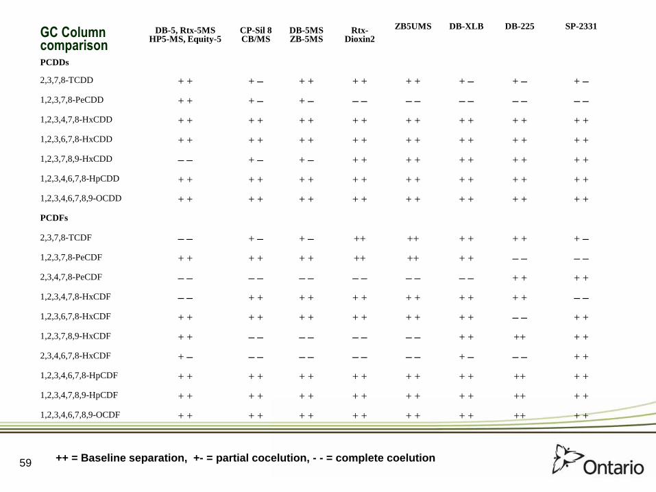
GC Column comparison
DB-5, Rtx-5MS HP5-MS, Equity-5
CP-Sil 8 CB/MS
DB-5MS ZB-5MS
Rtx- Dioxin2
ZB5UMS DB-XLB DB-225 SP-2331
PCDDs
2,3,7,8-TCDD + + + – + + + + + + + – + – + – 1,2,3,7,8-PeCDD + + + – + – – – – – – – – – – – 1,2,3,4,7,8-HxCDD + + + + + + + + + + + + + + + + 1,2,3,6,7,8-HxCDD + + + + + + + + + + + + + + + + 1,2,3,7,8,9-HxCDD – – + – + – + + + + + + + + + + 1,2,3,4,6,7,8-HpCDD + + + + + + + + + + + + + + + + 1,2,3,4,6,7,8,9-OCDD + + + + + + + + + + + + + + + + PCDFs 2,3,7,8-TCDF – – + – + – ++ ++ + + + + + – 1,2,3,7,8-PeCDF + + + + + + ++ ++ + + – – – – 2,3,4,7,8-PeCDF – – – – – – – – – – – – + + + + 1,2,3,4,7,8-HxCDF – – + + + + + + + + + + + + – – 1,2,3,6,7,8-HxCDF + + + + + + + + + + + + – – + + 1,2,3,7,8,9-HxCDF + + – – – – – – – – + + ++ + + 2,3,4,6,7,8-HxCDF + – – – – – – – – – + – – – + + 1,2,3,4,6,7,8-HpCDF + + + + + + + + + + + + ++ + + 1,2,3,4,7,8,9-HpCDF + + + + + + + + + + + + ++ + + 1,2,3,4,6,7,8,9-OCDF + + + + + + + + + + + + ++ + +
++ = Baseline separation, +- = partial cocelution, - - = complete coelution 59

from Tondeur, Biomed. Environ. Mass Spectrom. 14 449 (1987)
Potential interferences in TCDD analysis
60

Compound Ion Resolution Interferent Needed
Nonachlorobiphenyl 321.8491 7,236 No Pentachlorobiphenylene 321.8677 12,432 Yes Heptachlorobiphenyl 321.8678 12,480 Yes Hydroxytetrachlorodibenzofuran 321.8936 Infinity Yes – removed in cleanup DDE 321.9292 9,044 No Polychloroxanthenes 321.9114 18,089 Yes Tetrachloromethoxybiphenyl 321.9299 8,870 No
61
Potentially interfering compounds to consider

62
Column Performance
win/res mix-f dlp-cs4 back
15.50 16.00 16.50 17.00 17.50 18.00 18.50 19.00 19.50Time0
100
%
jan10_02std3 2: Voltage SIR 25 Channels EI+ 321.8936
1.89e7
1289-tcdd
\1237/1238-tcdd
2378-tcdd
1234-tcdd
5% phenyl-methyl column

63
TCDF Ion Channel for Flyash Extract c101863-0004
21.00 21.50 22.00 22.50 23.00 23.50 24.00 24.50Time0
100
%
0
100
%
may12_res15 2: Voltage SIR 20 Channels EI+ 303.9016
5.90e523.60
22.52
21.67
20.8821.08
21.53
21.76
21.9022.20
22.03
22.40
23.3323.14
22.69 22.84
23.01
23.67
23.8724.57
may12_res15 2: Voltage SIR 20 Channels EI+ 317.9389
9.97e623.49
13C12-2,3,7,8-tcdf
Flyash Extract

64 64
Comparison of GC Columns Column Length (m) 20 60 40
Inner diameter (mm) 0.1 0.25 0.18
Film thickness (µm) 0.1 0.25 0.18
Theoretical plates/m 8,600 3,300 5,300
Total plates (for column) 172,000 198,000 212,000
Calculated no. plates (T4CDD) 176,000 230,000 285,000
Relative Efficiency 0.93 1 1.03
Relative Anal. Time 0.33 1 0.55
Need 175,000 plates to separate critical pair – 1,2,3,7/1,2,3,8 and 2,3,7,8 TCDD

65
Changes in parameters • shorter & narrower columns • thinner stationary phase films • faster oven temperature programming rates • higher pressures, faster carrier gas flow rates
Faster analyses ⇒ increased sample throughput Narrower peak widths place new demands on detection systems
Fast GC – Method Attributes

66
What is Fast GC ?
GC ramp rates >50ºC/min. GC column diameters <0.18 mm Stationary phase <0.18 µm GC column head pressures >60 psi Phase ratio: β = r / df r = column diameter df = film thickness

67
Handbook of GC/MS – H.J. Huebschmann
Comparison of Different Column Dimensions
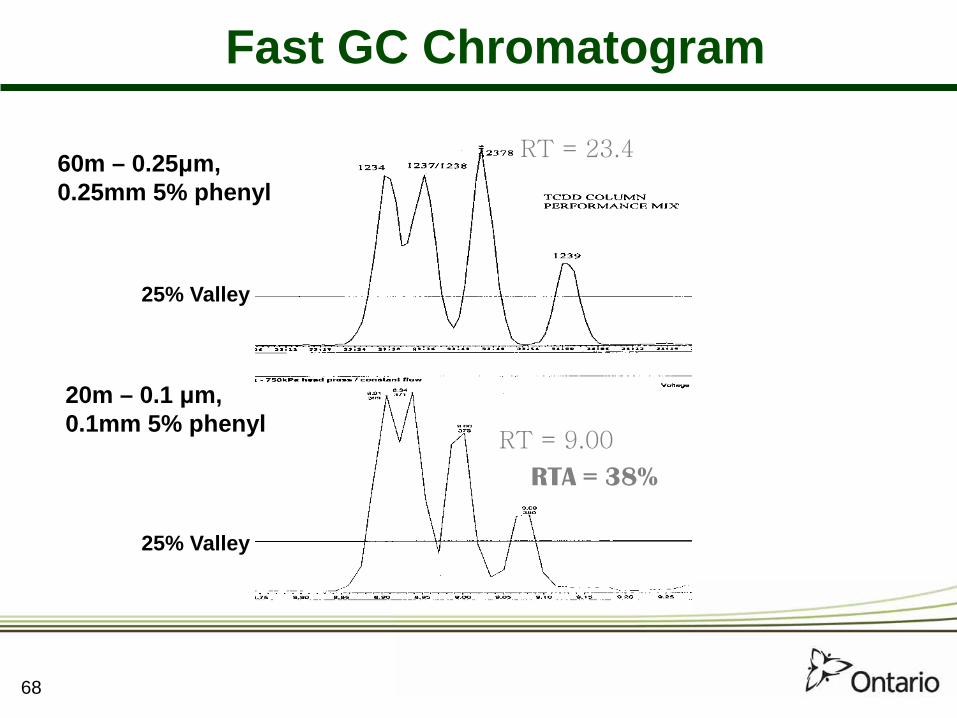
68
25% Valley
25% Valley
60m – 0.25μm, 0.25mm 5% phenyl
20m – 0.1 μm, 0.1mm 5% phenyl
RTA = 38%
RT = 23.4
RT = 9.00
Fast GC Chromatogram

How many data points are necessary to correctly characterize a chromatographic peak?
69

Seven to ten points per
peak is optimum
70

71
Reduction in Analysis Time Using Microbore Columns
60 m (.25/.25)
40 m (.18/.18)
30 m (.25/.25)
20 m (.10/.10)
10 m (.10/.10)
Dioxins [50] 28 (44%) 14 (72%)
PCB Congeners [90] 18 (80%)
PAH [40] 22 (55%) 14 (65%)
OC Pesticides [55] 12* (78%)

72 72
Parallel Columns
• Most compound classes cannot be uniquely separated on a single chromatographic phase – e.g., PCBs, dioxins, PAHs
• Extracts must be separated or analyzed on 2 phases• Parallel columns can be used to analyze multiple
fractions simultaneously• e.g., dioxins/furans/coplanar PCBs and ortho PCBs
• Extracts can also be analyzed separately• Analysis and confirmation in the same run • Both columns must be temperature compatible

73 73
Parallel Column Advantages
Mono-ortho PCBs elute from 20m column well before PCDD/Fs elute from 40 m column
DPEs, and interfering PCBs in mono-ortho DLPCB sample fraction
Avoid potential interferences: 1) Furan formation in ion source 2) Reduces coelution of higher chlorinated PCBs with
coplanars (i.e., PCB 110 with PCB 77)

74 74
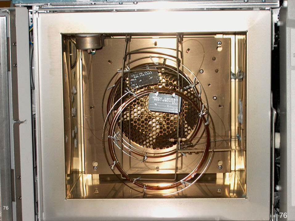
GC Configuration
HP6890 + model GC • 2 injection ports and 2 autosamplers
2 GC Columns • Dioxin/furan & coplanar PCBs injected on
40 m Rtx5, 0.18 mm x 0.20 µm
• Mono-ortho PCBs – 20 m Rtx5, 0.1 mm x 0.1 µm

75 75
The Gas Chromatograph
76 76 76 76

77 77
123 \
118/ 114
/
105/
167156 \
157/
81 \
77/
126 169
2378-TCDD
12378-PCDD 123478-HxCDD \
123678-HxCDD /123789-HxCDD
/ 123478-HpCDD/
OCDD
Fraction 1: 20 mMono Ortho PCBs
Fraction 2: 40 mCoplanar PCBs
Fraction 2: 40 mTetra – Octa PCDDs
189/
78 78
7.50 10.00 12.50 15.00 17.50 20.00 22.50 25.00 27.50 30.00 32.50 35.00 37.50 40.00Time0
100
%
0
100
%
0
100
%
7.50 10.00 12.50 15.00 17.50 20.00 22.50 25.00 27.50 30.00 32.50 35.00 37.50 40.00Time0
100
%
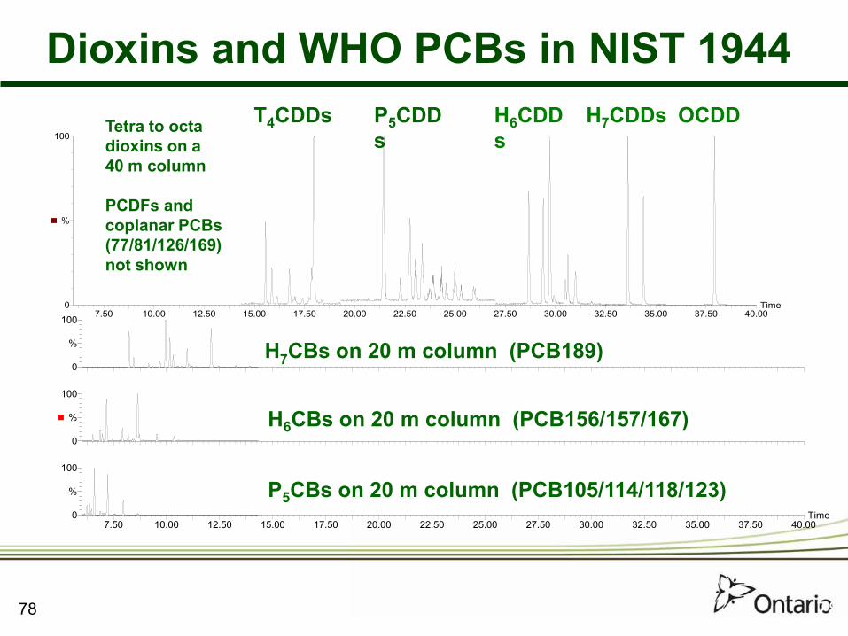
P5CBs on 20 m column (PCB105/114/118/123)
H6CBs on 20 m column (PCB156/157/167)
H7CBs on 20 m column (PCB189)
Tetra to octa dioxins on a 40 m column
PCDFs and coplanar PCBs (77/81/126/169) not shown
T4CDDs P5CDDs
H6CDDs
H7CDDs OCDD
Dioxins and WHO PCBs in NIST 1944

79
Dioxin/Furan Results Comparison
NIST 1944
MARINE SED.
Single
(pg/g)
Dual
(pg/g)
Ref. Value
(pg/g) 2378-TCDD 136 128 133 ± 9
12378-PCDD 19 22 19 ± 2
123478-HxCDD 29 27 26 ± 3
23478-PCDF 48 45 45 ± 4
OCDF 1300 1200 1100 ± 100
79
80
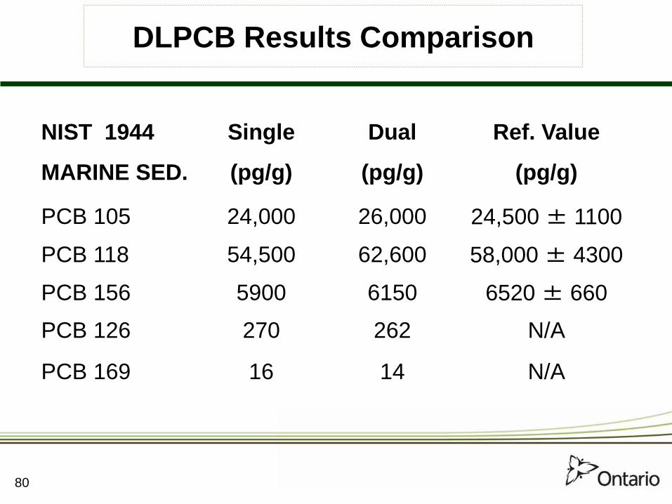
DLPCB Results Comparison
NIST 1944
MARINE SED.
Single
(pg/g)
Dual
(pg/g)
Ref. Value
(pg/g)
PCB 105 24,000 26,000 24,500 ± 1100
PCB 118 54,500 62,600 58,000 ± 4300
PCB 156 5900 6150 6520 ± 660
PCB 126 270 262 N/A
PCB 169 16 14 N/A
81 81
Two-Dimensional GC (GC×GC)
• Produces higher peak capacity (more chromatographic peaks per space). Increases peak capacity to 50 × 20 = 1000 compounds
• Eliminates the need for second column confirmation. Can do multiple analyte groups in same run and may eliminate need for extract fractionation
• Fast analysis – requires fast detector – e.g., time-of-flight mass spectrometer (TOFMS), ECD
• Provides structured chromatograms for excellent selectivity
• Provides much more information
• Results in increased sensitivity

82 82
Injector
1D 2DModulator
TOFMS
1tR
PM
Y
X
2tRY2tRX
X+Y
InjectorInjector
1D 2DModulator
TOFMSTOFMS
1tR
PM
Y
X
2tRY2tRX
X+Y
PM = modulation time D = dimension
GC×GC Schematic Diagram
Retention Time (tR)
Modulator
82
83 83
1tR
2tR
Signal
YX
XY1tRX
1tRY
2tRY2tRX
1tR
2tR
Signal
YX
XY1tRX
1tRY
2tRY2tRX
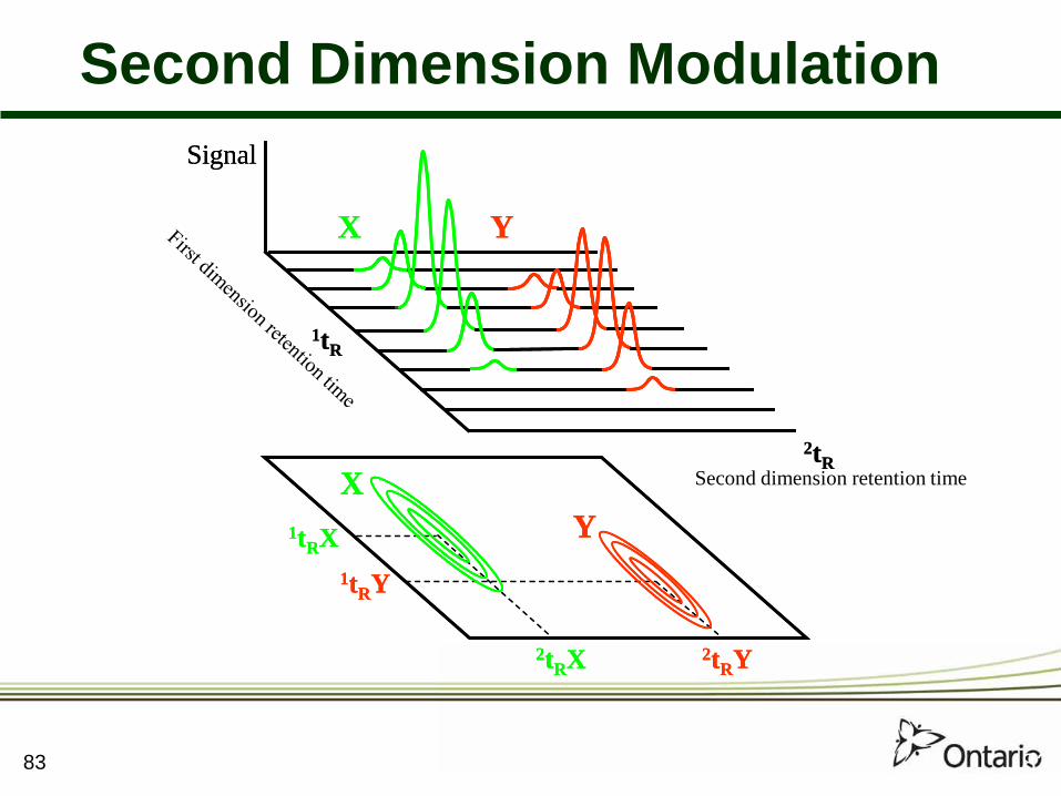
Second Dimension Modulation
Second dimension retention time
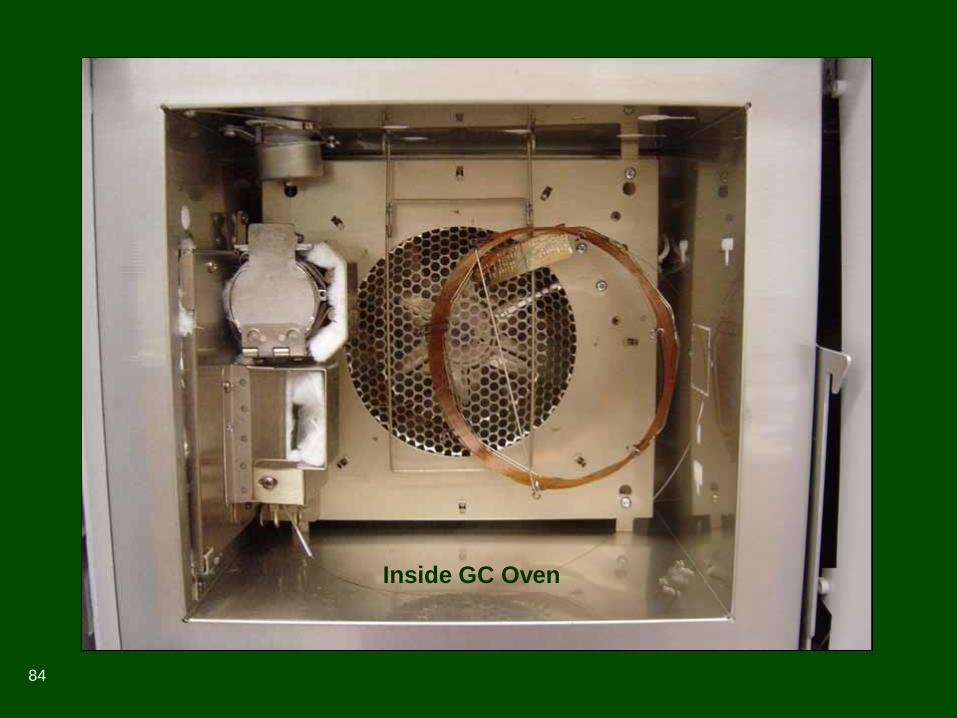
Inside GC Oven
84
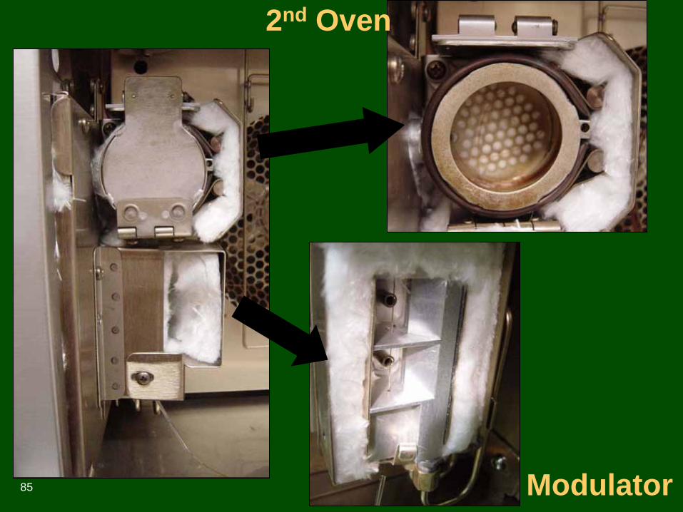
2nd Oven
Modulator 85
86 86
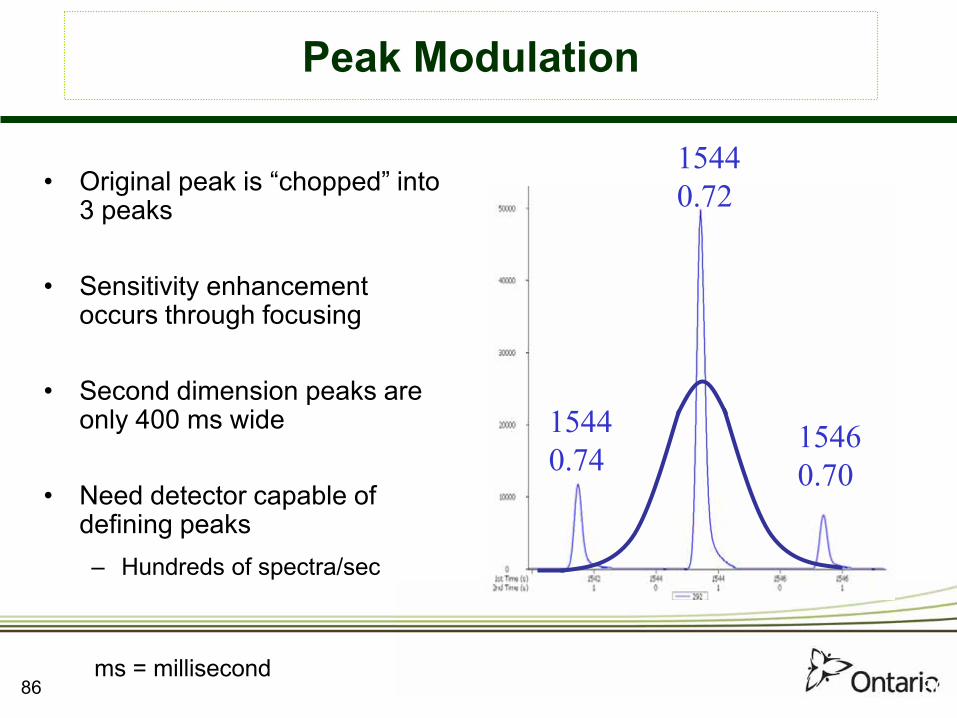
Peak Modulation
15440.74
15440.72
15460.70
• Original peak is “chopped” into 3 peaks
• Sensitivity enhancement occurs through focusing
• Second dimension peaks are only 400 ms wide
• Need detector capable of defining peaks– Hundreds of spectra/sec
ms = millisecond

87 87
Comprehensive GC×GC
Form of 2DGC: Orthogonal Column Setup
1st Dimension (Column) Standard (10–60 m, 0.25 mm, 0.25 um) Non-polar (DB-1, Rtx-5)
2nd Dimension (Column)
Very short (1–2 m) Narrow bore, thin film (0.10–0.18 mm, 0.10–0.18 um) Polar or shape selective (DB-1701, Rtx-PCB)

88 88
PCBs Challenging Separations DB5-10M/0.18/0.18_DB17-2M/0.1/0.1

89 89
PCB Standard by GC×GC-ECD Orthogonal Elution
206*209
194205*
208*199*
189
169
157156170
126
183*
128167
177171
202
191*
201
180
187178*
158138
149
188*
123
153168*
8177
114
118
105
95
155*
10199
119
87 110*
151*49
104*
44
3774 70
18*
15
54*
33
28
22
52
819
PCB STD (BP-MS)
*to be confirmed by GCxGC/TOF-MS
Deca-
Nona-Octa-
Hepta-
Hexa-
Penta-
Tetra-
Tri-
Di-

90 90
Dioxin-Like PCBs vs. Other PCBs
81
m/z 292 326 360 394
Rtx-1 >
Rtx
-PC
B >
123118
114
189169
157156
167
126
10577

91
Sediments by GC×GC-ECD
676
1
2176 1676 1176
2
3
0
2nd D
imen
sion
(s)
1st Dimension (s)
Unknown compounds
PCBs/OCs
CBz PCNs, PCDEs
Dioxins/Furans
PCA bands

GCxGC-TOFMS of sediment sample C for chlorinated dioxins and furans
40m x 0.18mm x 0.18µm Rtx-Dioxin2
1m x
0.1
5mm
x 0
.15µ
m R
xi-1
7Sil
MS

GCxGC-TOFMS of sediment sample C for chlorinated dioxins and furans
40m x 0.18mm x 0.18µm Rtx-Dioxin2
1m x
0.1
5mm
x 0
.15µ
m R
xi-1
7Sil
MS
m/z ions plotted: 306 322 340 356 374 390 408 424 444 460
Dioxin/furan elution area…

GCxGC-TOFMS of sediment sample C for chlorinated dioxins and furans, zoom
1m x
0.1
5mm
x 0
.15µ
m R
xi-1
7Sil
MS
40m x 0.18mm x 0.18µm Rtx-Dioxin2
2378 TCDD
Only m/z 322 is plotted. Note isobaric interferences eluting below 2378 TCDD that would interfere in 1D GC.

GCxGC-TOFMS of sediment sample B for chlorinated dioxins and furans, zoom
1m x
0.1
5mm
x 0
.15µ
m R
xi-1
7Sil
MS
40m x 0.18mm x 0.18µm Rtx-Dioxin2
While looking for Cl6 PCBs (m/z 360), we see some interesting later-eluting peaks… Cl6
PCBs

GCxGC-TOFMS of sediment sample B for chlorinated dioxins and furans, zoom
1m x
0.1
5mm
x 0
.15µ
m R
xi-1
7Sil
MS
40m x 0.18mm x 0.18µm Rtx-Dioxin2
Dibromopyrenes!

97 97
Background
Muir & Howard, ES&T, 2006, 40, 7157-7166US TSCA – United States Toxic Substances Control Act

98
Stockholm Agreement Compounds
Original 12 Added 2009 Under Discussion aldrin, chlordane, dieldrin, DDT, endrin, heptachlor, hexachlorobenzene (HCB), mirex, toxaphene, polychlorinated biphenyls (PCBs), polychlorinated dibenzodioxins (PCDD) and dibenzofurans (PCDF)
chlordecone, α-hexachlorocyclohexane, β-hexachlorocyclohexane, hexabromobiphenyl, tetra- to hepta-bromodiphenylether, lindane, (δ-hexachlorocyclohexane), pentachlorobenzene, perfluoroctanesulfonic acid (PFOS), its salts and perfluoroctanesulfonyl fluoride
short chain chlorinated paraffins (SCCPs), endosulfan, hexabromocyclododecane (HBCD)

99
Sediment CRM – Lake Ontario
Analysis Time: 7.3 minutes
CRM = certified reference material

100 100
Sediment CRM – Target Compounds
2 1. Phenanthrene 2. Anthracene 3. Fluoranthene 4. Pyrene 5. Benzofluoranthenes 6. Benzo[e]pyrene 7. Benzo[a]pyrene 8. Perylene
1 3 5
4 6
7 8
101 101
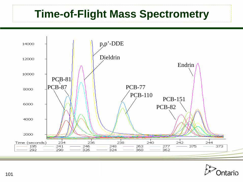
Time-of-Flight Mass Spectrometry
PCB-87 PCB-81
p,p’-DDE
PCB-77 PCB-110
PCB-82 PCB-151
Endrin Dieldrin

102
PAHs, PCBs & Organochlorine Pesticides by GC-TOF
g-Chlordane
Pyrene
PCB-101
PCB-99
Endosulphan-1
a-Chlordane
PCB-119
103
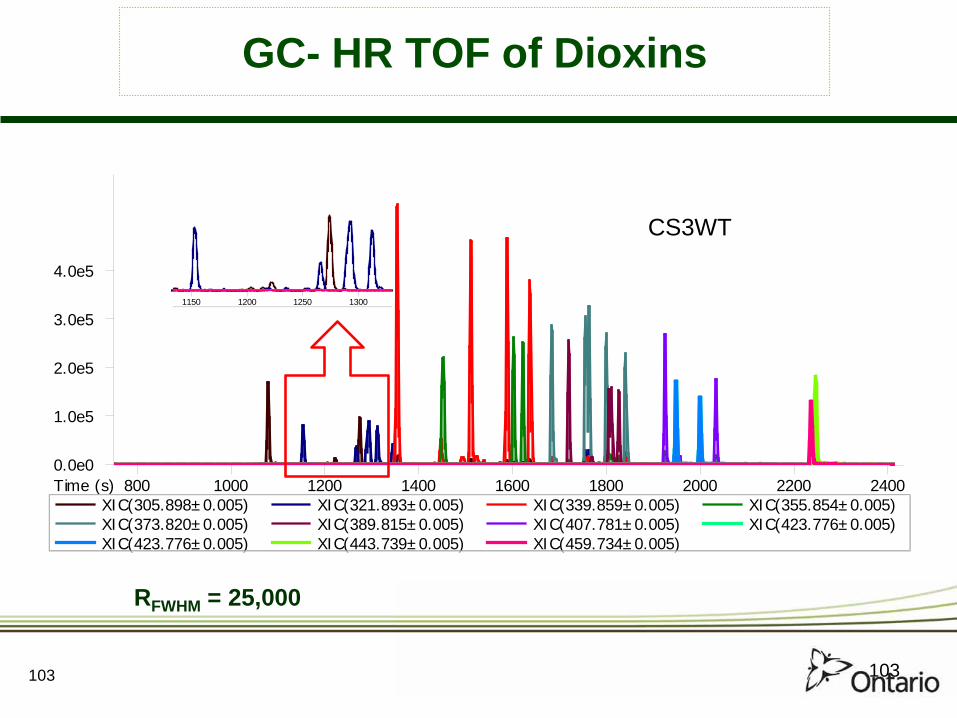
GC- HR TOF of Dioxins
800 1000 1200 1400 1600 1800 2000 2200 24000.0e0
1.0e5
2.0e5
3.0e5
4.0e5
Time (s)XIC(305.898±0.005) XIC(321.893±0.005) XIC(339.859±0.005) XIC(355.854±0.005)XIC(373.820±0.005) XIC(389.815±0.005) XIC(407.781±0.005) XIC(423.776±0.005)XIC(423.776±0.005) XIC(443.739±0.005) XIC(459.734±0.005)
1150 1200 1250 1300
CS3WT
RFWHM = 25,000
103
104
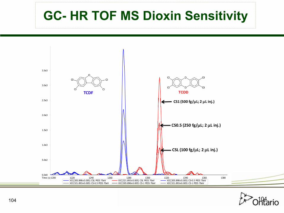
GC- HR TOF MS Dioxin Sensitivity
1200 1220 1240 1260 1280 1300 1320 1340 1360 13800.0e0
5.0e2
1.0e3
1.5e3
2.0e3
2.5e3
3.0e3
3.5e3
Time (s)XIC(305.898±0.005) CSL PEIS 70eV XIC(321.893±0.005) CSL PEIS 70eV XIC(305.898±0.005) CS-0.5 PEIS 70eVXIC(321.893±0.005) CS-0.5 PEIS 70eV XIC(305.898±0.005) CS-1 PEIS 70eV XIC(321.893±0.005) CS-1 PEIS 70eV
TCDF TCDF
CS1 (500 fg/µL; 2 µL inj.)
CS0.5 (250 fg/µL; 2 µL inj.)
CSL (100 fg/µL; 2 µL inj.)
TCDD
104

105
HR TOF MS Full Scan Data
OCDF
OCDD
105

106
GC- HRTOF MS – Additional Compounds
700 800 900 1000 1100 1200 1300 14000.0e0
2.0e4
4.0e4
6.0e4
8.0e4
1.0e5
Time (s)
Name Similarity Formula Mass Accuracy (ppm)1-Chloropyrene 913 C16H9Cl -0.21
4-Phenyldibenzofuran 879 C18H12O 0.35Benzo[2,1-b:3,4-b']bisbenzofuran 891 C18H10O2 0.22
Pyreno[4,5-b]furan (CAS) 918 C18H10O 0.211,3-Dichlorobenzo[c]phenanthrene 821 C18H10Cl2 0.13
106

107
12 14 16 18 200.0e0
3.0e5
6.0e5
9.0e5
1.2e6
1.5e6
1.8e6
2.1e6
2.4e6
2.7e6
Time (minutes)
Name Formula RDBE Mass Accuracy (ppm)Benzo[ghi]fluoranthene C18H10 14 -1.14Triphenylene C18H12 13 -0.89Benz[a]anthracene, 7-methyl- C19H14 13 -1.21Benzo[k]fluoranthene C20H12 15 -0.42
GC- HR TOF MS – Additional Compounds
107

Plastimet Fire – 1997
108

109
110,000 FWHM
2048K data points
29,000 FWHM
512K data points
7,000 FWHM
128K data points
1,500 FWHM
32K data points
Fourier Transform Mass Spectrometry
Ultrahigh resolution (The above mass range is 0.3 Da)
ROMS (Regular old mass spectrometer)
R=100,000
109

110

111
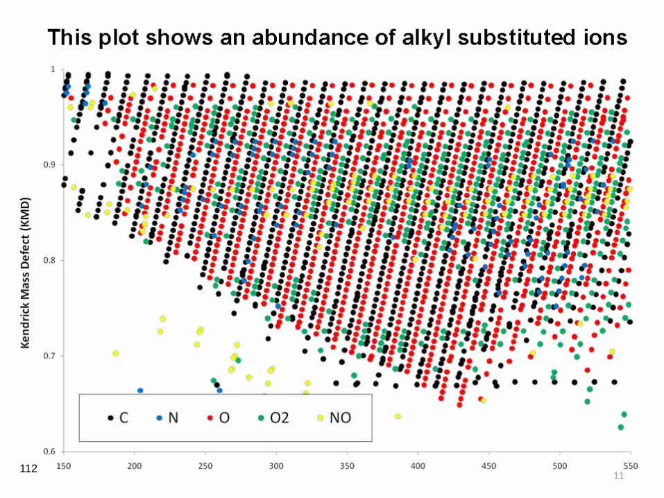
112

113

0
0.1
0.2
0.3
0.4
0.5
0.6
0.7
0.8
0.9
1
150 200 250 300 350 400 450 500 550
Ken
dric
k M
ass
Def
ect
Nominal Kendrick Mass
Kendrick plot - vegetation exposed to fallout from the 1997 Plastimet fire
unassignedCHCHClCHClOCHO
Kendrick Plot
Kendrick mass = mass x (35 / 34.9689)
114

115

116

117

118
Summary of Method Enhancements
• The analysis of dioxin and related compounds requires the most sensitive and selective instrumentation
• Most POPs sample preparation procedures can be automated or semi-automated and many can be combined to save money and time
• Fast GC, Parallel GC and GC×GC can significantly reduce sample analysis times and costs while increasing analytical capacity.
• Kendrick Plots can be used to identify unknown compounds.
• GC×GC can increase selectivity and sensitivity and can also be used for analytical triage. Extract fractionation may not be required.
• These enhancements can save time, costs and reduce the use of solvents and reagents.

4th Annual Multidimensional Chromatography Workshop
Toronto, Canada – January 8 & 9, 2013
Confirmed Speakers:
Daniela Cavgnino – Dani Jack Cochran – Restek John Dimandja – Collage Frank Dorman – Penn State Taduesz Gorecki – Waterloo Teruyo Ieda – Gerstel Philip Marriott – Monash University Brian McCarry – McMaster Jef Focant – U Liege John Seeley – Oakland University Heather Bean – Vermont Catherine Rawlinson – Murdoch U No Registration Fee
Contact Eric Reiner at : [email protected]
119
Thank You ! [email protected]
References:
E.J. Reiner, R.E. Clement, A.B. Okey, C.H. Marvin, “Advances in the Analysis of Polychlorinated Dibenzo-p-dioxins, Dibenzofurans and Dioxin-like Polychlorinated Biphenyls in Environmental Samples” Analytical and Bioanalytical Chemistry, 386, 791 (2006).
E.J. Reiner, A.R. Boden, T. Chen, K.A. MacPherson, A.M. Muscalu, Advances in the analysis of persistent halogenated organic compounds, LC GC Europe, February, 23(2), 60 (2010) E.J. Reiner, “Analysis of Dioxin and Related Compounds” Mass Spectrometry Reviews, 29(4), 526 (2010).
V.Y Taguchi, RJ Nieckarz, RE Clement. S Krolik, R Williams, Dioxin Analysis by Gas Chromatography-Fourier Transform Ion Cyclotron Resonance Mass Spectrometry (GC-FTICRMS), J Am Soc Mass Spectrom 21, 1918 (2010)
120