advances in series-compensated line protection
TRANSCRIPT

Advances in Series-Compensated Line Protection
Héctor J. Altuve, Joseph B. Mooney, and George E. Alexander Schweitzer Engineering Laboratories, Inc.
Presented at the 63rd Annual Georgia Tech Protective Relaying Conference
Atlanta, Georgia April 22–24, 2009
Previously presented at the 62nd Annual Conference for Protective Relay Engineers, March 2009
Previous revised edition released October 2008
Originally presented at the 35th Annual Western Protective Relay Conference, October 2008

1
Advances in Series-Compensated Line Protection
Héctor J. Altuve, Joseph B. Mooney, and George E. Alexander, Schweitzer Engineering Laboratories, Inc.
Abstract—In this paper, after an overview of transmission line series compensation, we review series-compensated line protection challenges, that include voltage inversion, current inversion, and distance estimation errors. We then present modern solutions to improve directional, distance, and differential element operation on series-compensated lines. Later we provide relay setting guidelines. Finally, we present and discuss several cases of protection scheme operation for actual faults.
I. INTRODUCTION Transmission line series compensation increases power
transfer capability and improves power system stability. However, series compensation increases the fault current level and may also cause generator subsynchronous resonance. The capacitive reactance XC is typically from 25 percent to 75 percent of the line inductive reactance XL. The authors have also seen lines compensated to 100 percent.
Series capacitors may be installed at one or both line ends. Line ends are typical capacitor locations, because it is generally possible to use space available in the substation. In turn, this reduces installation cost. Another possibility is to install the series capacitors at some central location on the line. Series capacitors located at the line ends create more complex protection problems than those installed at the center of the line.
Series capacitors require spark gaps or metal oxide varistors (MOVs) to reduce or eliminate overvoltages across the capacitors. Spark gaps (see Fig. 1) flash over to remove the capacitor when the voltage exceeds a given value, but they may not fire for low-current faults. Thus, the line protection scheme must also perform properly with the series capacitor still in operation.
SparkGap
BypassSwitch
DischargeReactor
SeriesCapacitor
Fig. 1 Spark gaps flash over to fully remove the capacitor when voltage exceeds a given value
MOVs clamp the voltage and change the series capacitor impedance in a nonlinear fashion (see Fig. 2). MOV operation
does not fully remove the series capacitor. Some schemes include MOV energy monitoring. The MOV bypasses the series capacitor when the MOV energy level exceeds a threshold.
BypassSwitch
DischargeReactor
SeriesCapacitor
MOV
Triggered Air Gap
Fig. 2 MOVs clamp the voltage and change the impedance without fully removing the capacitor
Series-compensated lines present unique challenges for directional, distance, and differential elements because the transient response of the series capacitor is not readily predictable. Conduct transient studies and tests to ensure secure and dependable operation of relays in series-compensated line applications.
This paper reviews series-compensated line protection challenges and presents modern solutions to improve directional, distance, and differential element operation on series-compensated lines. The paper also provides relay setting recommendations and presents several cases of protection scheme operation for actual faults.
II. SERIES-COMPENSATED LINE PROTECTION CHALLENGES The line reactance change and the subharmonic-frequency
oscillations caused by the series capacitors may affect line protective relays. Series capacitors can also generate high-frequency transients. The analog and digital filters in microprocessor-based relays attenuate all high-frequency components [1]. Therefore, high-frequency transients have very little effect on most modern relays.
A. Voltage Inversion Affects Directional Discrimination A voltage inversion is a change of 180 degrees in the
voltage phase angle. For elements responding to phase quantities, voltage inversion can occur for a fault near a series capacitor if the impedance from the relay to the fault is
2
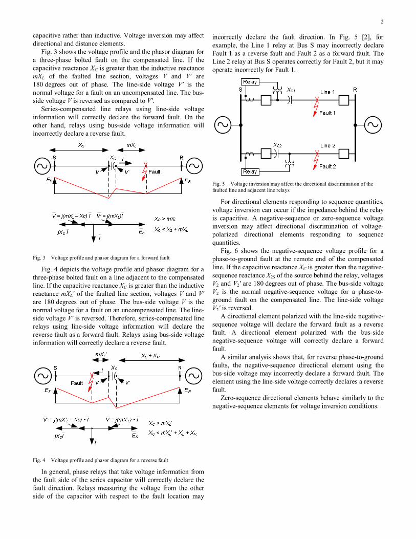
capacitive rather than inductive. Voltage inversion may affect directional and distance elements.
Fig. 3 shows the voltage profile and the phasor diagram for a three-phase bolted fault on the compensated line. If the capacitive reactance XC is greater than the inductive reactance mXL of the faulted line section, voltages V and V' are 180 degrees out of phase. The line-side voltage V' is the normal voltage for a fault on an uncompensated line. The bus-side voltage V is reversed as compared to V'.
Series-compensated line relays using line-side voltage information will correctly declare the forward fault. On the other hand, relays using bus-side voltage information will incorrectly declare a reverse fault.
Fig. 3 Voltage profile and phasor diagram for a forward fault
Fig. 4 depicts the voltage profile and phasor diagram for a three-phase bolted fault on a line adjacent to the compensated line. If the capacitive reactance XC is greater than the inductive reactance mXL' of the faulted line section, voltages V and V' are 180 degrees out of phase. The bus-side voltage V is the normal voltage for a fault on an uncompensated line. The line-side voltage V' is reversed. Therefore, series-compensated line relays using line-side voltage information will declare the reverse fault as a forward fault. Relays using bus-side voltage information will correctly declare a reverse fault.
Fig. 4 Voltage profile and phasor diagram for a reverse fault
In general, phase relays that take voltage information from the fault side of the series capacitor will correctly declare the fault direction. Relays measuring the voltage from the other side of the capacitor with respect to the fault location may
incorrectly declare the fault direction. In Fig. 5 [2], for example, the Line 1 relay at Bus S may incorrectly declare Fault 1 as a reverse fault and Fault 2 as a forward fault. The Line 2 relay at Bus S operates correctly for Fault 2, but it may operate incorrectly for Fault 1.
Fig. 5 Voltage inversion may affect the directional discrimination of the faulted line and adjacent line relays
For directional elements responding to sequence quantities, voltage inversion can occur if the impedance behind the relay is capacitive. A negative-sequence or zero-sequence voltage inversion may affect directional discrimination of voltage-polarized directional elements responding to sequence quantities.
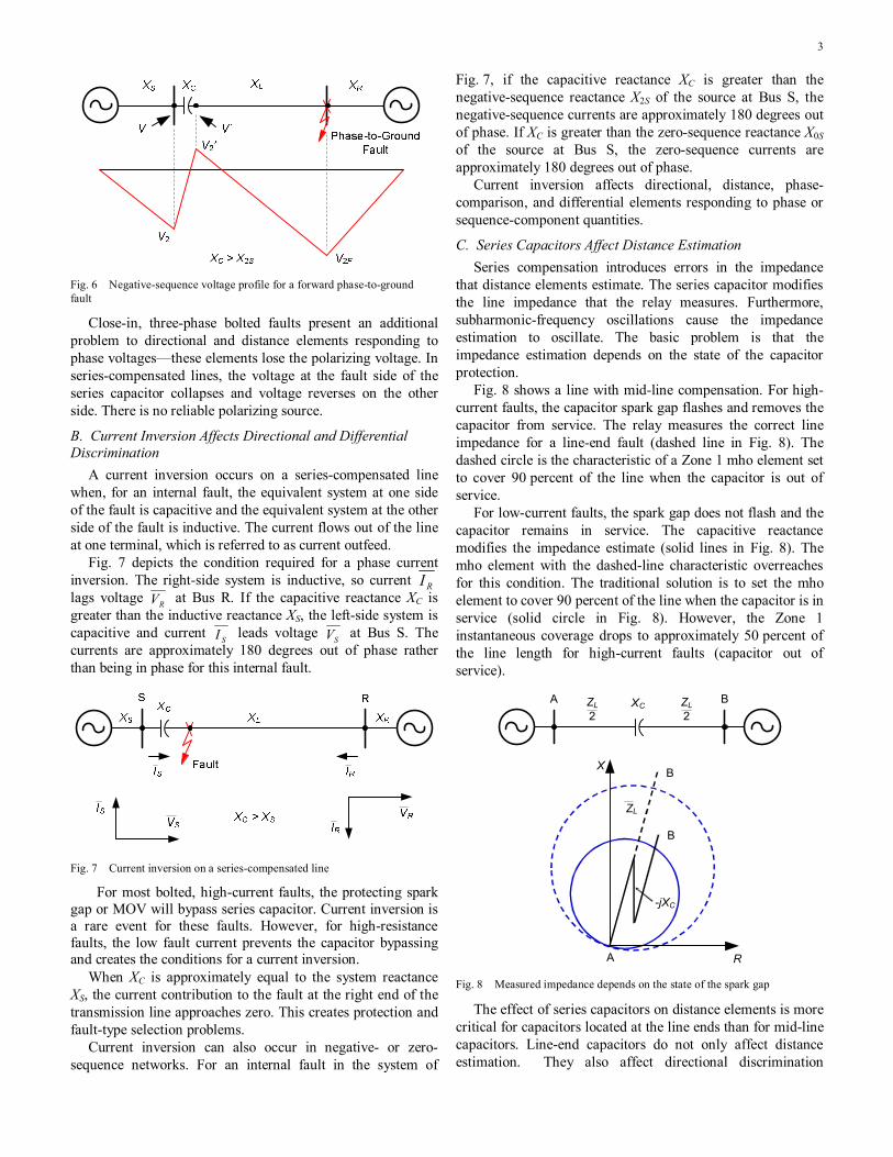
Fig. 6 shows the negative-sequence voltage profile for a phase-to-ground fault at the remote end of the compensated line. If the capacitive reactance XC is greater than the negative-sequence reactance X2S of the source behind the relay, voltages V2 and V2' are 180 degrees out of phase. The bus-side voltage V2 is the normal negative-sequence voltage for a phase-to-ground fault on the compensated line. The line-side voltage V2' is reversed.
A directional element polarized with the line-side negative-sequence voltage will declare the forward fault as a reverse fault. A directional element polarized with the bus-side negative-sequence voltage will correctly declare a forward fault.
A similar analysis shows that, for reverse phase-to-ground faults, the negative-sequence directional element using the bus-side voltage may incorrectly declare a forward fault. The element using the line-side voltage correctly declares a reverse fault.
Zero-sequence directional elements behave similarly to the negative-sequence elements for voltage inversion conditions.
3
Fig. 6 Negative-sequence voltage profile for a forward phase-to-ground fault
Close-in, three-phase bolted faults present an additional problem to directional and distance elements responding to phase voltages—these elements lose the polarizing voltage. In series-compensated lines, the voltage at the fault side of the series capacitor collapses and voltage reverses on the other side. There is no reliable polarizing source.
B. Current Inversion Affects Directional and Differential Discrimination
A current inversion occurs on a series-compensated line when, for an internal fault, the equivalent system at one side of the fault is capacitive and the equivalent system at the other side of the fault is inductive. The current flows out of the line at one terminal, which is referred to as current outfeed.
Fig. 7 depicts the condition required for a phase current inversion. The right-side system is inductive, so current RI lags voltage RV at Bus R. If the capacitive reactance XC is greater than the inductive reactance XS, the left-side system is capacitive and current SI leads voltage SV at Bus S. The currents are approximately 180 degrees out of phase rather than being in phase for this internal fault.
Fig. 7 Current inversion on a series-compensated line
For most bolted, high-current faults, the protecting spark gap or MOV will bypass series capacitor. Current inversion is a rare event for these faults. However, for high-resistance faults, the low fault current prevents the capacitor bypassing and creates the conditions for a current inversion.
When XC is approximately equal to the system reactance XS, the current contribution to the fault at the right end of the transmission line approaches zero. This creates protection and fault-type selection problems.
Current inversion can also occur in negative- or zero-sequence networks. For an internal fault in the system of
Fig. 7, if the capacitive reactance XC is greater than the negative-sequence reactance X2S of the source at Bus S, the negative-sequence currents are approximately 180 degrees out of phase. If XC is greater than the zero-sequence reactance X0S of the source at Bus S, the zero-sequence currents are approximately 180 degrees out of phase.
Current inversion affects directional, distance, phase-comparison, and differential elements responding to phase or sequence-component quantities.
C. Series Capacitors Affect Distance Estimation Series compensation introduces errors in the impedance
that distance elements estimate. The series capacitor modifies the line impedance that the relay measures. Furthermore, subharmonic-frequency oscillations cause the impedance estimation to oscillate. The basic problem is that the impedance estimation depends on the state of the capacitor protection.
Fig. 8 shows a line with mid-line compensation. For high-current faults, the capacitor spark gap flashes and removes the capacitor from service. The relay measures the correct line impedance for a line-end fault (dashed line in Fig. 8). The dashed circle is the characteristic of a Zone 1 mho element set to cover 90 percent of the line when the capacitor is out of service.
For low-current faults, the spark gap does not flash and the capacitor remains in service. The capacitive reactance modifies the impedance estimate (solid lines in Fig. 8). The mho element with the dashed-line characteristic overreaches for this condition. The traditional solution is to set the mho element to cover 90 percent of the line when the capacitor is in service (solid circle in Fig. 8). However, the Zone 1 instantaneous coverage drops to approximately 50 percent of the line length for high-current faults (capacitor out of service).
B
X
RA
B
ZL
-jXC
BA XCZL2
ZL2
Fig. 8 Measured impedance depends on the state of the spark gap
The effect of series capacitors on distance elements is more critical for capacitors located at the line ends than for mid-line capacitors. Line-end capacitors do not only affect distance estimation. They also affect directional discrimination

4
because of voltage inversion. Mid-line capacitors do not affect directional discrimination unless the level of series compensation is very high.
Fig. 9 depicts a line with the capacitor located at one line end. The figure also shows the characteristic of the Zone 1 element protecting the compensated line (solid circle) and the characteristic of the Zone 1 element (dashed circle) protecting an adjacent line (not shown in the figure). In this example, both mho elements receive voltage signals from voltage transformers (VTs) connected to Bus A.
For high-current faults on Line AB, the spark gap takes the capacitor out of service. Both mho elements perform correctly for this condition. For low-current faults, the capacitor remains in service. If the fault is located close to the capacitor, the measured impedance is out of the compensated-line relay characteristic. The relay sees this fault as a reverse fault and restrains. On the other hand, the measured impedance lies within the characteristic of the adjacent-line relay and causes this relay to operate incorrectly.
B
X
RA
B
A’
ZL
-jXC
A’
XC
ZLBA
Fig. 9 Line-end capacitors are more critical for distance elements than mid-line capacitors
Fig. 10 is the result of a computer simulation showing the spiraling impedance resulting from the subharmonic-frequency transient [2]. The series capacitor is located at the remote line end. The circle represents the steady-state characteristic of a Zone 1 mho element set with a 2.5-ohm reach. This setting represents a best guess to prevent Zone 1 overreach for a remote bus fault based on the steady-state impedance. Immediately after fault inception, the impedance trajectory passes through the mho-element characteristic. As the transient decays, the impedance spiral decreases until it reaches a steady-state value after approximately five cycles. Fig. 10 shows that, to prevent Zone 1 operation during the subharmonic-frequency transient, you must further reduce the mho element reach setting.
0 2
X (O
hms)
1-1-2
4
3
2
1
0
R (Ohms)
Fig. 10 In series-compensated lines, distance elements can overreach because of the impedance oscillation caused by the subharmonic-frequency transient
III. SERIES-COMPENSATED LINE PROTECTION SOLUTIONS
A. Memory Polarization for Mho and Directional Elements Responding to Phase Quantities
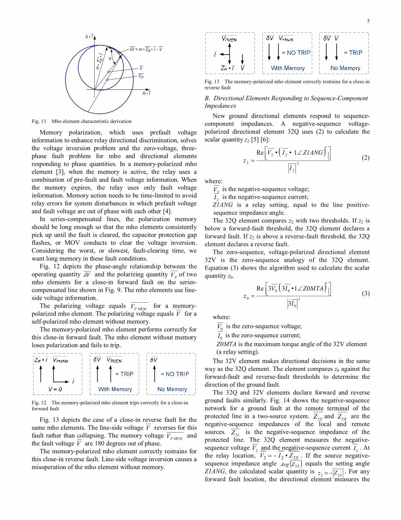
A mho element tests the angle θ between a line-drop-compensated voltage Vδ , given by (1), and a polarizing or reference voltage PV .
VIZmV R −= ••δ (1)
where: m is the pu reach in terms of the replica impedance;
RZ is the replica line impedance (a relay setting); I is the measured current; V is the measured voltage. When θ = 90 degrees, the relationship between Vδ and PV
is any point on the mho circle, as shown in Fig. 11. A self-polarized mho element uses the measured voltage
V as the polarizing voltage ( VVP = ). The mho circle crosses by the origin of coordinates. However, V is very small for close-in faults and the relay may fail to operate.
The fault should not affect the polarizing quantity PV . Typical polarizing quantities for mho elements are positive-sequence voltages or unfaulted phase voltages. These polarizing quantities shift the circle to the third quadrant for forward faults (as shown in Fig. 11) and to the first quadrant for reverse faults. These polarizing quantities are reliable for close-in unbalanced faults, but these quantities may fail for voltage inversion conditions and close-in three-phase faults. Reference [3] describes the mho element polarizing choices available.
5
X • I
R • I
VP
m •
Z R • I θ
V
δV = m • ZR • I – V
Fig. 11 Mho element characteristic derivation
Memory polarization, which uses prefault voltage information to enhance relay directional discrimination, solves the voltage inversion problem and the zero-voltage, three-phase fault problem for mho and directional elements responding to phase quantities. In a memory-polarized mho element [3], when the memory is active, the relay uses a combination of pre-fault and fault voltage information. When the memory expires, the relay uses only fault voltage information. Memory action needs to be time-limited to avoid relay errors for system disturbances in which prefault voltage and fault voltage are out of phase with each other [4].
In series-compensated lines, the polarization memory should be long enough so that the mho elements consistently pick up until the fault is cleared, the capacitor protection gap flashes, or MOV conducts to clear the voltage inversion. Considering the worst, or slowest, fault-clearing time, we want long memory in these fault conditions.
Fig. 12 depicts the phase-angle relationship between the operating quantity Vδ and the polarizing quantity PV of two mho elements for a close-in forward fault on the series-compensated line shown in Fig. 9. The mho elements use line-side voltage information.
The polarizing voltage equals MEMPV for a memory-polarized mho element. The polarizing voltage equals V for a self-polarized mho element without memory.
The memory-polarized mho element performs correctly for this close-in forward fault. The mho element without memory loses polarization and fails to trip.
Fig. 12 The memory-polarized mho element trips correctly for a close-in forward fault
Fig. 13 depicts the case of a close-in reverse fault for the same mho elements. The line-side voltage V reverses for this fault rather than collapsing. The memory voltage MEMPV and the fault voltage V are 180 degrees out of phase.
The memory-polarized mho element correctly restrains for this close-in reverse fault. Line-side voltage inversion causes a misoperation of the mho element without memory.
Fig. 13 The memory-polarized mho element correctly restrains for a close-in reverse fault
B. Directional Elements Responding to Sequence-Component Impedances
New ground directional elements respond to sequence-component impedances. A negative-sequence voltage-polarized directional element 32Q uses (2) to calculate the scalar quantity z2 [5] [6]:
( )
2
2
22
2
1Re
I
Z1ANG I Vz
⎥⎦⎤
⎢⎣⎡ ∠
=
∗
•• (2)
where: 2V is the negative-sequence voltage; 2I is the negative-sequence current;
Z1ANG is a relay setting, equal to the line positive-sequence impedance angle. The 32Q element compares z2 with two thresholds. If z2 is
below a forward-fault threshold, the 32Q element declares a forward fault. If z2 is above a reverse-fault threshold, the 32Q element declares a reverse fault.
The zero-sequence, voltage-polarized directional element 32V is the zero-sequence analogy of the 32Q element. Equation (3) shows the algorithm used to calculate the scalar quantity z0.
( )
2
0
00
03
133Re
I
Z0MTA I V z ⎥⎦
⎤⎢⎣⎡ ∠
=
∗
• (3)
where:
0V is the zero-sequence voltage;
0I is the zero-sequence current; Z0MTA is the maximum torque angle of the 32V element (a relay setting).
The 32V element makes directional decisions in the same way as the 32Q element. The element compares z0 against the forward-fault and reverse-fault thresholds to determine the direction of the ground fault.
The 32Q and 32V elements declare forward and reverse ground faults similarly. Fig. 14 shows the negative-sequence network for a ground fault at the remote terminal of the protected line in a two-source system. SZ2 and RZ2 are the negative-sequence impedances of the local and remote sources. LZ2 is the negative-sequence impedance of the protected line. The 32Q element measures the negative-sequence voltage 2V and the negative-sequence current 2I . At the relay location, SZ•I V 222 −= . If the source negative-sequence impedance angle ( )SZ Arg 2 equals the setting angle Z1ANG, the calculated scalar quantity is
SZz 22 −= . For any forward fault location, the directional element measures the

6
negative-sequence impedance of the equivalent system behind the relay. A similar analysis shows that, for all reverse ground faults, the scalar quantity is
RL ZZz 222 += , corresponding to the negative-sequence impedance of the equivalent system in front of the relay.
Fig. 14 Negative-sequence network for a ground fault at the end of the protected line on a two-source system
Fig. 15 shows the operating characteristic of the 32Q (Fig. 15(a)) and 32V (Fig. 15(b)) elements and the calculated z2 and z0 values for forward and reverse faults. For simplicity, we consider the power system to be purely inductive and assume the maximum torque angle (Z1ANG and Z0MTA, respectively) set to 90 degrees. For the 32Q element, we use
L1Z instead of LZ2 in Fig. 15(a). Recall that LL1 ZZ 2= for lines.
Fig. 15 Operating characteristics of the 32Q and 32V directional elements Because the z2 (or z0) values for forward and reverse faults
are of opposite signs, there is a good margin for setting the forward-fault and reverse-fault thresholds. The smallest separation between these values occurs when the sources at both line ends are infinite (Z2S = Z2R = 0 or Z0S = Z0R = 0). For forward faults z2 = 0 (or z0 = 0) and for reverse faults
LZz 22 = (or
LZz 00 = ). Set the forward-fault (Z2F, Z0F) and reverse-fault (Z2R, Z0R) thresholds at approximately one-half of the corresponding sequence line impedance. Separate these thresholds to create a security band between them.
Proper settings provide correct operation during voltage inversion of directional elements measuring sequence-component impedance (see section IV). References [2] and [7] provide guidelines for setting negative-sequence directional elements on series-compensated lines. Perform digital simulation studies to validate the proposed setting of the protection scheme.
C. Preventing Distance Element Overreach Reference [8] describes a relay logic that detects when a
fault occurs beyond a series capacitor. The relay blocks the
Zone 1 element until the series-compensation logic determines that the fault is between the relay and the series capacitor.
Fig. 16 shows a series-compensated line to illustrate the logic. The relay calculates a voltage CALCV , assuming that the fault is beyond the series capacitor. Then the relay determines the ratio of the measured voltage magnitude VMEAS to the calculated voltage magnitude VCALC and compares this ratio with a threshold value.
Fig. 16 The series-compensation relay logic blocks the Zone 1 element when the fault is beyond the series capacitor
For example, for an A-phase-to-ground fault, the A-phase element calculates the voltage: ( ) ( ) ACrALCALC IjXIkIZV •• −+⋅+= 01 (4)
where:
AI is the A-phase current at the relay location;
rI is the residual current at the relay location; k0 is the zero-sequence compensation factor;
1LZ is the positive-sequence line impedance; XC is the series capacitor reactance.
Fig. 17 is a plot of the measured voltage, the calculated voltage, and the ratio of measured to calculated voltage for faults along the compensated line. Ignoring fault resistance and mutual coupling, the calculated voltage equals the measured voltage for a fault at Bus R. The ratio of the measured to calculated voltage equals one.
When the fault moves to the line side of the series capacitor, the fault current decreases, the measured voltage increases, and the calculated voltage decreases. The measured voltage increases because the series capacitor is no longer between the relay and the fault and the measured line impedance increases. The calculated voltage decreases because it always includes the series capacitor. The ratio of the measured to calculated voltage is greater than one for a fault at this location.
As the fault nears the relay, the measured voltage decreases, the calculated voltage increases, and their ratio decreases.

7
VMEASThreshold
VCALC
S R
Relay
Z1LXC
Ratio
1
Fig. 17 The measured voltage, the calculated voltage, and their ratio vary as the fault location moves along the series-compensated line
The series-compensation logic compares the ratio of measured voltage to calculated voltage with a predefined threshold. When the ratio is less than the threshold, the Zone 1 distance element can operate. Otherwise, the logic blocks the Zone 1 element.
With the series-compensation logic, you can set the Zone 1 reach based on the uncompensated line impedance. The only additional information that the relay needs to calculate this ratio is the amount of capacitive reactance XC to be measured by the relay. The value of this XC setting depends on the position of the series capacitor relative to the relay voltage transformers.
D. Directional Comparison Scheme Security Much of the existing series-compensated line protection
literature focuses on the problems associated with distance and directional functions. While directional integrity and overreach are important issues, the viability of the directional comparison scheme logic is equally important. For instance, additional transient blocking logic may be necessary to provide adequate security against undesired operations where directional integrity cannot be maintained for slow clearing faults.
Relays using memory polarization, especially those using positive-sequence memory polarization, are very secure and do not require special logic. However, relays that do not have adequate memory polarization may require additional logic to ensure secure operation for slow clearing external faults.
E. Alpha Plane Differential Elements Traditional line differential schemes have percentage
differential elements, which compare operating signal IOP with restraining signal IRT. The element operates when IOP is greater than a percentage of IRT and also greater than a minimum pickup current. The element operating characteristic is typically a plot of IOP as a function of IRT.
The best way to analyze differential element operation is on the current-ratio complex plane, or Alpha Plane. You can superimpose the relay characteristic on the Alpha Plane and the current-ratio trajectory resulting from the fault or abnormal condition on the power system. For a transmission line, the
Alpha Plane complex variable is the ratio of the remote current RI to the local current LI .
Fig. 18 depicts the Alpha Plane representation of power system load and fault conditions [9]. For ideal through-current conditions (load flow or external faults), the magnitudes of LI and RI are equal and their phases are 180 degrees apart. Therefore, °∠= 1801LR I/I . Therefore, through-load and external fault conditions plot at point 1∠180° on the Alpha Plane.
Im
Load and External Fault Conditions
Internal Faults With Outfeed at L
Internal Faults
ReIRIL
( (
IRIL
( (Internal Faults With Outfeed at R
1∠180°
Fig. 18 Alpha Plane representation of power system load and fault conditions, including the effect of channel-delay compensation errors
For internal faults, currents LI and RI are in phase under ideal conditions. These faults plot on the positive real axis of the Alpha Plane. In general, the angles of LI and RI for internal faults depend on the source voltage angles (prefault load flow condition) and the angles of the system impedances at both sides of the fault point. Fig. 18 shows the internal fault region on the Alpha Plane as an angular sector that accommodates source voltage and impedance angle differences.
For some internal faults, the current flows out of the line at one terminal [9]. In series-compensated lines, outfeed occurs when the reactance from one of the sources to the fault point is capacitive (see Section II.B). High-resistance internal faults with fault current less than load current also cause outfeed conditions. A three-terminal line with a strong external parallel tie between two terminals can experience outfeed at one terminal for some internal faults.
For internal faults with outfeed at one line terminal, the angle between LI and RI is close to 180 degrees. The magnitudes for such angles are not equal. These faults plot close to the negative real axis of the Alpha Plane, but they do not coincide with the 1∠180° point, as Fig. 18 shows.
Channel-delay compensation errors cause the current ratio to rotate around the origin on the Alpha Plane. The ratio magnitude is unchanged. The rotation angle equals the angle error caused by channel asymmetry. Fig. 18 shows how the channel asymmetry expands the fault and load regions.
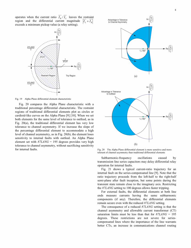
Fig. 19 shows the Alpha Plane line differential element characteristic [9]. The restraint region includes the 1∠180 degrees point and perfectly fits the shape of the through-load and external fault region Fig. 18 depicts. Setting 87LANG determines the angular extent of the restraint region. Setting 87LR determines the restraint region outer radius. The inner radius is the reciprocal of 87LR. The differential element
8
operates when the current ratio LR I/I leaves the restraint region and the differential current magnitude RL II + exceeds a minimum pickup value (a relay setting).
Trip RegionRestraint Region
Re
Im
87LANG2
87LANG2
187LR
1∠180°
87LR
IRIL
( (
IRIL
( (
Fig. 19 Alpha Plane differential element characteristic
Fig. 20 compares the Alpha Plane characteristic with a traditional percentage differential characteristic. The restraint regions of traditional differential elements plot as circles or cardioid-like curves on the Alpha Plane [9] [10]. When we set both elements for the same level of tolerance to outfeed, as in Fig. 20(a), the traditional differential element has very low tolerance to channel asymmetry. If we increase the slope of the percentage differential element to accommodate a high level of channel asymmetry, as in Fig. 20(b), the element loses sensitivity to internal faults with outfeed. An Alpha Plane element set with 87LANG = 195 degrees provides very high tolerance to channel asymmetry, without sacrificing sensitivity for internal faults.
Advantage in Tolerance to Channel Asymmetry
(a)
Advantage in Tolerance to Outfeed
(b)
IRIL
( (
ImIRIL
( (
ReIRIL
( (
ImIRIL
( (
1∠180°
1∠180°Re
Fig. 20 The Alpha Plane differential element is more sensitive and more tolerant of channel asymmetry than traditional differential elements
Subharmonic-frequency oscillations caused by transmission line series capacitors may delay differential relay operation for internal faults.
Fig. 21 shows a typical current-ratio trajectory for an internal fault on the series-compensated line [9]. Note that the ratio trajectory proceeds from the left-half to the right-half semi-plane after fault inception, but some points during the transient state remain close to the imaginary axis. Restricting the 87LANG setting to 100 degrees allows faster tripping.
For external faults, the differential elements at both line ends measure currents having the same subharmonic components (if any). Therefore, the differential elements remain secure even with the reduced 87LANG setting.
The consequence of a reduced 87LANG setting is that the channel asymmetry and allowable current transformer (CT) saturation limits must be less than that for 87LANG = 195 degrees. These restrictions are not severe for series-compensated lines where the importance of the line warrants better CTs, an increase in communications channel routing

9
attention, and operating instructions to the communications company.
Fig. 21 Subharmonic-frequency oscillations on series-compensated lines may delay differential element operation
IV. RELAY SETTING RECOMMENDATIONS
A. Underreaching Distance Elements (Zone 1) When a Zone 1 distance element is applied on a series-
compensated system, it is critical to the overall security of the protection that the Zone 1 distance element does not operate for any faults outside the protected line. As we noted previously, the subharmonic-frequency transients that can occur on series-compensated systems cause overreach of Zone 1 elements.
Zone 1 distance element settings depend on the following factors:
• Series capacitor location • Capacitor and line impedances • Type of capacitor protection • Protective level of the capacitor protection
Setting a Zone 1 element in a series-compensated line application can be difficult because of subharmonic-frequency transients and the relay filter response. General setting guidelines provide a starting point for setting the Zone 1 element. However, proper distance relay settings in actual series-compensated line applications must be verified by using transient testing with data obtained from an Electromagnetic Transients Program (EMTP/ATP) or by testing in a Real-Time Digital Simulator (RTDS) environment.
In applications using spark gap protection on the series capacitor where the spark gap fires for external faults, set the Zone 1 element to 80 percent of the compensated line impedance ( CL jXZ −1 ). For applications where the spark gap does not fire for external faults or MOVs are used for capacitor bank protection, set the Zone 1 reach to 50 percent of the compensated line impedance.
In this case, XC is the total capacitive reactance the Zone 1 distance element measures and could include internal as well
as external series capacitors [7]. For example, in the system of Fig. 22, the protected line does not include series capacitors. However, there is a series capacitor on an adjacent line. The Zone 1 element at Bus S must be set to accommodate the external series capacitor.
Fig. 22 External series capacitor
If the infeed at Bus S is sufficient to ensure that the external series capacitor is bypassed for any close-in faults, then the Zone 1 distance elements at Bus S may be set as if there is no external series capacitor. If there is no bypass of the capacitor for external faults, the Zone 1 distance elements at Bus S must be set considering the external series capacitor. In addition, the infeed must also be considered, as it will increase the apparent capacitive reactance the relay at Bus S measures.
Section III.C and reference [8] describe a relay supervisory logic to detect when a fault occurs beyond a series capacitor. Because the supervisory logic determines when the Zone 1 element operates, set the reach of the Zone 1 element based on the uncompensated line impedance. Set the capacitive reactance value equal to the total capacitive reactance the relay measures, both internal and external. Be sure to account for infeed as we described previously.
B. Overreaching Distance Elements for Pilot Schemes In general, the series capacitors have little effect on the
settings of overreaching pilot distance elements. In some cases, the subharmonic-frequency transients the series capacitors introduced can cause the overreaching elements to momentarily drop out. This could delay tripping, but it will not result in a failure to trip. If the series capacitor has MOV protection, conduction of the MOVs can cause the fault to appear more resistive than if the capacitor has spark gap protection. For these reasons, the reach of the pilot zone distance elements should be set beyond the value uncompensated systems normally use. We recommend a minimum reach of 150 percent of the line impedance.
C. Negative-Sequence Directional Elements References [5], [11], and [12] discuss negative-sequence
directional element setting on uncompensated systems. In this paper, we will focus on setting directional elements in series-compensated systems. We must also maintain proper time coordination between the forward and reverse directional overcurrent elements.
1) Mid-Line Series Compensation Fig. 23 shows a line with the series capacitor installed in
the middle of the line. If we assume the sources to be infinite, a negative-sequence directional element measures z2 = 0 for forward faults and CL jXZz −= 22 for reverse faults (see

10
Section III.B). If we assume LL ZZ 21 = and considering the line to be purely inductive, z2 = Z1L – XC for reverse faults.
Fig. 23 Mid-line series capacitor
Equations (5) and (6) provide the suggested impedance settings for the system of Fig. 23.
2
1 CL XZ Z2F −= (5)
0.1 Z2F Z2R += (6) where:
Z1L is the magnitude of the line positive-sequence impedance. XC is the capacitive reactance of the series capacitor.
The negative-sequence directional elements at Buses S and R will have the same Z2F and Z2R impedance settings. The impedance settings will be the same whether the line or bus side of the circuit breaker supplies the relay potential.
2) Compensation at One Line End Fig. 24 shows a line with a series capacitor located at one
end of the line and with the bus side of the series capacitor supplying the relay potentials. The relay potential can be supplied from VTs on the bus or from VTs located between the circuit breaker and the series capacitor. The relay settings are the same for this case as for the case of Fig. 23 (Equations (5) and (6)).
Fig. 24 Series capacitor at one end, bus-side potential
Fig. 25 shows a line with the series capacitor located at one end of the line and with the line side of the series capacitor supplying the relay potentials.
Fig. 25 Series capacitor at one end, line-side potential
Because the line side of the series capacitor supplies the potential for the relay at Bus S, the capacitive reactance is part of the source impedance behind the relay at Bus S. If XC is greater than the magnitude of the positive-sequence source impedance behind the relay, a voltage inversion could occur for faults in the forward direction. This could cause the relay
to select the improper direction for the fault. In order to prevent this, the Z2F setting at Bus S must be greater than XC.
Equations (6) and (7) provide the suggested impedance settings for the relay at Bus S in the system of Fig. 25.
C
CL XXZ Z2F +−=2
1 (7)
Equations (5) and (6) provide the suggested impedance settings for the relay at Bus R in the system of Fig. 25.
The negative-sequence directional elements at Buses S and R will have different Z2F and Z2R impedance settings.
3) Compensation at Both Line Ends Fig. 26 shows a line with series capacitors located at both
ends of the line and with the bus side of the series capacitors supplying the relay potentials. Either the VTs on the bus or from those between the circuit breaker and the series capacitor can supply the relay potential. The reactances of the two capacitors may be different.
Fig. 26 Series capacitors at both line ends, bus-side potential
Equations (6) and (8) provide the suggested impedance settings for the system of Fig. 26.
( )2
1 CRCSL XXZ Z2F +−= (8)
The negative-sequence directional elements at Buses S and R will have the same impedance settings.
Fig. 27 shows a line with series capacitors located at both line ends and with the line side of the series capacitors supplying the relay potentials.
Fig. 27 Series capacitors at both line ends, line-side potential
Equations (6) and (9) provide the suggested impedance settings for the relay at Bus S in the system of Fig. 27.
( )CS
CSCRL XXXZ Z2F ++−=2
1 (9)
Equations (6) and (10) provide the suggested impedance settings for the relay at Bus R in the system of Fig. 27.
( )CR
CSCRL XXXZ Z2F ++−=2
1 (10)
The negative-sequence directional elements at Buses S and R may have different impedance settings if the capacitor reactances are not the same.
11
D. Line Differential Elements Line differential protection is an excellent choice for series-
compensated lines. Line differential elements are immune to voltage inversion. The Alpha Plane differential elements described in Section III.E [9] are very tolerant to current inversion and subharmonic-frequency transients.
The line differential element should be set to maximize dependability, as it is unlikely that CT saturation would occur for an out-of-section fault. Channel asymmetry and load flow should still be considered when setting the differential characteristic.
Current inversion can result in a failure to trip when you use line differential elements. This is because the current appears to be through-fault current but of differing magnitudes. You can set the Alpha Plane differential element characteristic to accommodate current inversion, if you know the magnitude of the outfeed current and the contribution from the remote terminal. Calculate the ratio of the outfeed current to the remote current. If this value is less than eight, then you can set the element to operate reliably for current inversion.
Subharmonic-frequency transients can result in slow operation of the differential element. As CT saturation is not a concern, the angular thresholds of the Alpha Plane characteristic can be reduced. As Section III.E mentioned, you can set 87LANG to less than 195 degrees to increase operating speed for internal faults. Conduct transient studies and tests to select the 87LANG value.
E. Transient Testing Transient testing is critical to series-compensated line
applications to ensure secure and dependable operation of the protection scheme. The frequency of the subharmonic oscillations can change with source impedance changes, such as when a line or transformer is taken out of service. Thorough model power system testing allows verification of various system conditions and identifies problem areas before they can occur in the actual application. In addition, transient testing helps familiarize the protection engineer with the strengths and weaknesses of the protection system. This familiarity will aid in troubleshooting or identifying problems in the future.
V. ANALYSIS OF FIELD CASES This section analyzes actual faults on series-compensated
systems. Events that result in the conditions this paper describes are difficult to come by, as the fault must occur in particular locations on the line. However, these events can demonstrate that the relay is operating securely and dependably.
The first example is from a fault on a 500 kV series-compensated system. There are parallel 500 kV lines, both compensated at 70 percent with capacitors located at both line ends. As all of the lines are compensated at the line ends on these systems, protecting the lines can be quite challenging.
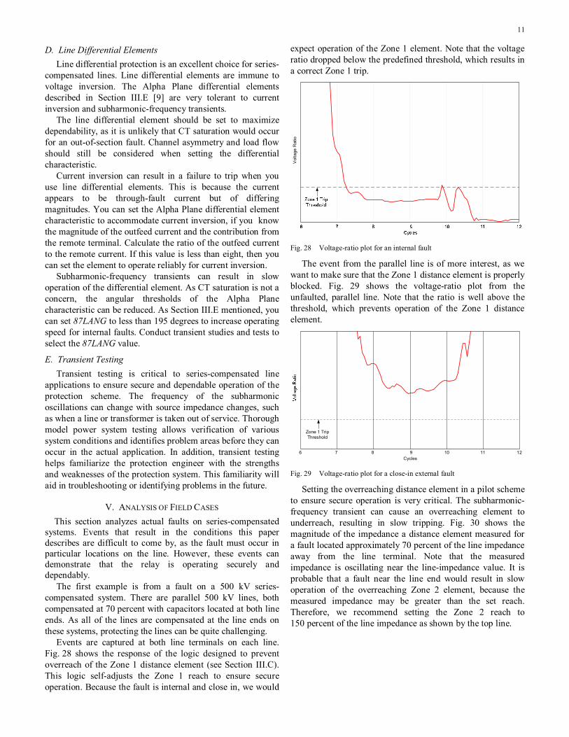
Events are captured at both line terminals on each line. Fig. 28 shows the response of the logic designed to prevent overreach of the Zone 1 distance element (see Section III.C). This logic self-adjusts the Zone 1 reach to ensure secure operation. Because the fault is internal and close in, we would
expect operation of the Zone 1 element. Note that the voltage ratio dropped below the predefined threshold, which results in a correct Zone 1 trip.
Vol
tage
Rat
io
Fig. 28 Voltage-ratio plot for an internal fault
The event from the parallel line is of more interest, as we want to make sure that the Zone 1 distance element is properly blocked. Fig. 29 shows the voltage-ratio plot from the unfaulted, parallel line. Note that the ratio is well above the threshold, which prevents operation of the Zone 1 distance element.
Cycles6 1110987 12
Zone 1 Trip Threshold
Fig. 29 Voltage-ratio plot for a close-in external fault
Setting the overreaching distance element in a pilot scheme to ensure secure operation is very critical. The subharmonic-frequency transient can cause an overreaching element to underreach, resulting in slow tripping. Fig. 30 shows the magnitude of the impedance a distance element measured for a fault located approximately 70 percent of the line impedance away from the line terminal. Note that the measured impedance is oscillating near the line-impedance value. It is probable that a fault near the line end would result in slow operation of the overreaching Zone 2 element, because the measured impedance may be greater than the set reach. Therefore, we recommend setting the Zone 2 reach to 150 percent of the line impedance as shown by the top line.

12
Line Impedance
Present Zone 2 Setting
Recommended Zone 2 Setting
Measured Impedance
Cycles7 9 11 13 15
Fig. 30 Measured impedance for an internal Zone 2 fault
The third event shows a phase-to-phase internal fault on an end-of-line compensated 345 kV line. The relay potentials are measured on the bus side of the series capacitor. Therefore, the capacitor is between the relay potentials and the fault location. The fault current is not high enough to bypass the capacitor, which results in a voltage inversion.
Fig. 31 shows the angular difference between the measured prefault and faulted phase voltages. We can see that the faulted phase voltage is phase shifted by more than 90 degrees during the fault. The maximum phase shift before the fault clears is nearly 150 degrees.
Fig. 31 Angular difference between the measured prefault and faulted phase voltages
The voltage inversion for this phase-to-phase fault has less impact on the positive-sequence voltage. Fig. 32 shows the angular difference between the prefault and faulted positive-sequence voltages. We can see that the phase shift is much less than that of the phase voltage because of the contribution of the unfaulted phase voltage in the positive-sequence calculation. The maximum phase shift on the positive-
sequence voltage is 50 degrees. Adding polarizing memory further improves the positive-sequence-voltage polarized distance element.
This event shows the advantage of using a positive-sequence memory-polarized distance element in series-compensated line applications. A positive-sequence memory-polarized distance element is a very robust solution for series-compensated systems.
Ang
le in
Deg
rees
Fig. 32 Angular difference between the prefault and faulted positive-sequence voltages
VI. CONCLUSIONS
1) Voltage inversion can cause directional and distance elements to operate incorrectly. In particular, external faults may appear to be internal, and internal faults may appear to be external. Memory polarization and directional element offsets can make these elements secure for voltage inversions.
2) Current inversions are unlikely, but inversions may occur under certain conditions. Line current differential elements are more tolerant to current inversions than are directional or distance elements.
3) Zone 1 elements can overreach because of subharmonic-frequency oscillations. New logic available today prevents Zone 1 overreach and ensures secure operation of the Zone 1 element.
4) Overreaching distance elements in pilot schemes should be set to a larger value to accommodate the subharmonic-frequency oscillations. A greater reach ensures high-speed tripping.
5) Transient simulation and testing are recommended in series-compensated line protection applications to ensure dependable and secure scheme and relay settings.
VII. ACKNOWLEDGMENT The authors would like to thank Ed Taylor and Davis
Erwin of Pacific Gas and Electric, Tom Roseburg of Bonneville Power Administration, and Dave Angell and Cliff Harris of Idaho Power Company for their contribution of the line fault events.

13
VIII. REFERENCES
[1] E. O. Schweitzer, III and D. Hou, “Filtering for Protective Relays,” in 19th Annual Western Protective Relay Conference.
[2] G. E. Alexander, J. Mooney, and W.Z. Tyska, “Advanced Application Guidelines for Ground Fault Protection,” in 28th Annual Western Protective Relay Conference.
[3] E. O. Schweitzer, III and J. B. Roberts, “Distance Relay Element Design,” in 19th Annual Western Protective Relay Conference.
[4] D. Hou, A. Guzmán, and J. B. Roberts, “Innovative Solutions Improve Transmission Line Protection,” in 24th Western Protective Relay Conference.
[5] J. B. Roberts and A. Guzmán, “Directional Element Design and Evaluation,” in 21st Annual Western Protective Relay Conference.
[6] A. Guzmán, J. B. Roberts, and D. Hou, “New Ground Directional Elements Operate Reliably for Changing System Conditions,” in 23rd Annual Western Protective Relay Conference.
[7] J. B. Mooney and G. B. Alexander, Applying the SEL-321 Relay on Series-Compensated Systems, SEL Application Guide AG2000-11.
[8] A. Guzman, J. Mooney, G. Benmouyal, and N. Fischer, “Transmission Line Protection for Increasing Power System Requirements,” in 55th Annual Conference for Protective Relay Engineers, Texas A&M University.
[9] J. B. Roberts, D. A. Tziouvaras, G. Benmouyal, and H. J. Altuve, “The Effect of Multiprinciple Line Protection on Dependability and Security,” in 55th Annual Protective Relaying Conference at the Georgia Institute of Technology.
[10] G. Benmouyal and T. Lee, “Securing Sequence-current Differential Elements,” in 31st Annual Western Protective Relay Conference.
[11] Joe Mooney, Daqing Hou, Charlie Henville, and Frank Plumtre, “Computer-Based Relay Models Simplify Relay-Application Studies,” 20th Annual Western Protective Relay Conference.
[12] Joe Mooney and Jackie Peer, “Application Guidelines for Ground Fault Protection,” 24th Annual Western Protective Relay Conference.
IX. BIOGRAPHIES
Héctor J. Altuve received his B.S.E.E. in 1969 from the Central University of Las Villas, Santa Clara, Cuba, and his Ph.D. in 1981 from Kiev Polytechnic Institute, Kiev, Ukraine. From 1969 until 1993, Dr. Altuve served on the faculty of the Electrical Engineering School at the Central University of Las Villas. He served as professor of the Graduate Doctoral Program in the Mechanical and Electrical Engineering School at the Autonomous University of Nuevo León, Monterrey, Mexico, from 1993 to 2000. In 1999 and 2000, he was the Schweitzer visiting professor at Washington State University’s Department of Electrical Engineering. In January 2001, Dr. Altuve joined Schweitzer Engineering Laboratories, Inc., where he is currently a Distinguished Engineer and Director of Technology for Latin America. He has authored and coauthored more than 100 technical papers and holds three patents. His main research interests are in power system protection, control, and monitoring. Dr. Altuve is an IEEE Senior Member and a PES Distinguished Lecturer.
Joseph B. Mooney, P.E., received his B.S.E.E. from Washington State University in 1985. He joined Pacific Gas and Electric Company upon graduation as a System Protection Engineer. In 1989, he left Pacific Gas and Electric and was employed by Bonneville Power Administration as a System Protection Maintenance District Supervisor. In 1991, he left Bonneville Power Administration and joined Schweitzer Engineering Laboratories, Inc. as an Application Engineer. Shortly after starting with SEL, he was promoted to Application Engineering Manager. In 1999, he became Manager of the Power Engineering Group of the Research and Development department at SEL. He is a registered Professional Engineer in the states of California and Washington.
George E. Alexander holds a B.S.E.E. degree from Villanova University and an M.S.E.E. degree from Drexel University. He is a registered professional engineer in the state of Pennsylvania. He has over 30 years experience in the design and application of transmission line relaying, and holds several U.S. patents in this area. Mr. Alexander has been involved in the development and Model Power System testing of solid state, hybrid analog/digital and fully digital protective relaying systems. He joined Schweitzer Engineering Laboratories, Inc. in 1999, and is currently a senior field application engineer.
Previously presented at the 2009 Texas A&M Conference for Protective Relay Engineers.© 2009 IEEE – All rights reserved.
20081022 • TP6340-01