advanced transmission schemes for the 4 generation of mobile
TRANSCRIPT

Advanced Transmission Schemes
for the 4th Generation of Mobile
Communication Systems
Von der Fakultät Informatik, Elektrotechnik undInformationstechnik der Universität Stuttgart zur Erlangung der
Würde eines Doktor-Ingenieurs (Dr.-Ing.) genehmigteAbhandlung
Vorgelegt von
Philipp Frank
aus Nürtingen
Hauptberichter: Prof. Dr.-Ing. J. SpeidelMitberichter: Prof. Dr.-Ing. R. KaysTag der mündlichen Prüfung: 18. Juli 2011
Institut für Nachrichtenübertragung der Universität Stuttgart
2011


The dissertation at hand evolved from my research activities at the Deutsche TelekomLaboratories in Berlin and the Institute of Telecommunications at the University ofStuttgart.
Special thanks go to my professor, Dr.-Ing. Joachim Speidel, for giving me the op-portunity to work under his supervision. Numerous fruitful discussions and helpfulsuggestions have contributed to the success of this work.
Also, I cordially thank Prof. Rüdiger Kays for taking over the assessment of this thesis.
I express my sincere gratitude to Dr.-Ing. Gerhard Kadel, Heinz Droste and ManfredRosenberger of the Deutsche Telekom Laboratories Intelligent Wireless Technologies& Networks department for their considerate support and for providing me a produc-tive research environment. They were always open for questions and encouraged myresearch work. Moreover, I would like to thank all my colleagues at the DeutscheTelekom Laboratories for their constant assistance and the valuable discussions.
In particular, I would like to thank Dr.-Ing. Andreas Müller for his invaluable advicesand suggestions during our close collaboration for the last three years. I cannot overem-phasize the importance of his support. Without his commitment this work would nothave been possible.
Special thanks also go to my family and friends who contributed with manifold supportand who had always the right words of encouragement in di�cult moments.


Contents
Contents
Acronyms and Abbreviations ix
Notation and Frequently Used Symbols xi
Nomenclature xv
Abstract xvii
Kurzfassung xvii
1. Introduction 1
2. Cellular System Modeling 5
2.1. MIMO wireless channel . . . . . . . . . . . . . . . . . . . . . . . . . . . 72.1.1. The 3GPP spatial channel model . . . . . . . . . . . . . . . . . 82.1.2. Pathloss model . . . . . . . . . . . . . . . . . . . . . . . . . . . 112.1.3. Shadow fading model . . . . . . . . . . . . . . . . . . . . . . . . 12
2.2. Physical layer . . . . . . . . . . . . . . . . . . . . . . . . . . . . . . . . 142.2.1. Orthogonal frequency division multiple access . . . . . . . . . . 152.2.2. Single-carrier frequency division multiple access . . . . . . . . . 182.2.3. Transmission frame structure . . . . . . . . . . . . . . . . . . . 192.2.4. Reference and control signaling . . . . . . . . . . . . . . . . . . 20
2.2.4.1. Reference signals . . . . . . . . . . . . . . . . . . . . . 202.2.4.2. Control channel . . . . . . . . . . . . . . . . . . . . . . 23
2.2.5. Detection techniques . . . . . . . . . . . . . . . . . . . . . . . . 242.2.5.1. Zero-forcing detection . . . . . . . . . . . . . . . . . . 242.2.5.2. Linear minimum mean squared error detection . . . . . 252.2.5.3. Successive interference cancellation . . . . . . . . . . . 25
2.3. Medium access control layer . . . . . . . . . . . . . . . . . . . . . . . . 262.3.1. Radio resource scheduling . . . . . . . . . . . . . . . . . . . . . 262.3.2. Link adaptation . . . . . . . . . . . . . . . . . . . . . . . . . . . 272.3.3. HARQ protocol . . . . . . . . . . . . . . . . . . . . . . . . . . . 28
2.4. Link-to-system level interface . . . . . . . . . . . . . . . . . . . . . . . 30
3. Advances in Scheduling and Feedback Methods 33
3.1. Round-robin scheduling . . . . . . . . . . . . . . . . . . . . . . . . . . . 333.2. Proportional-fair scheduling . . . . . . . . . . . . . . . . . . . . . . . . 35
v

Advanced Transmission Schemes for the 4th Generation of Mobile Communication Systems
3.3. Feedback concepts . . . . . . . . . . . . . . . . . . . . . . . . . . . . . 363.3.1. CQI feedback . . . . . . . . . . . . . . . . . . . . . . . . . . . . 383.3.2. CSI feedback . . . . . . . . . . . . . . . . . . . . . . . . . . . . 40
3.3.2.1. CSI quantization . . . . . . . . . . . . . . . . . . . . . 413.3.2.2. Codebook design . . . . . . . . . . . . . . . . . . . . . 433.3.2.3. CSI-based SU-MIMO precoding . . . . . . . . . . . . . 463.3.2.4. CSI-based transmission scheme selection . . . . . . . . 46
3.4. Baseline system performance . . . . . . . . . . . . . . . . . . . . . . . . 473.4.1. Downlink results . . . . . . . . . . . . . . . . . . . . . . . . . . 483.4.2. Uplink results . . . . . . . . . . . . . . . . . . . . . . . . . . . . 52
4. Advanced Transmission Techniques for the Downlink 57
4.1. Enhanced MU-MIMO with CQI feedback . . . . . . . . . . . . . . . . . 584.1.1. Identi�cation of feasible user combinations . . . . . . . . . . . . 584.1.2. MU-MIMO rate estimation . . . . . . . . . . . . . . . . . . . . . 594.1.3. LMMSE detection for MU-MIMO transmission . . . . . . . . . 60
4.2. Enhanced MU-MIMO with CSI feedback . . . . . . . . . . . . . . . . . 614.2.1. Block diagonalization precoding . . . . . . . . . . . . . . . . . . 624.2.2. Regularized block diagonalization precoding . . . . . . . . . . . 634.2.3. Precoding based on multi-user eigenmode transmission . . . . . 64
4.3. MU-MIMO proportional fair scheduling . . . . . . . . . . . . . . . . . . 654.4. MU-MIMO system performance . . . . . . . . . . . . . . . . . . . . . . 68
5. Advanced Transmission Techniques for the Uplink 75
5.1. Inter-cell interference coordination . . . . . . . . . . . . . . . . . . . . . 765.1.1. Dynamic interference coordination . . . . . . . . . . . . . . . . 77
5.1.1.1. Scheduling procedure based on HII signaling . . . . . . 785.1.1.2. System performance of dynamic interference coordination 79
5.1.2. Cooperative interference-aware joint scheduling . . . . . . . . . 825.1.2.1. Joint scheduling procedure . . . . . . . . . . . . . . . . 825.1.2.2. Practical considerations . . . . . . . . . . . . . . . . . 865.1.2.3. System performance of joint scheduling . . . . . . . . . 87
5.2. Cooperative interference prediction . . . . . . . . . . . . . . . . . . . . 905.2.1. Enhanced link adaptation . . . . . . . . . . . . . . . . . . . . . 905.2.2. Practical considerations . . . . . . . . . . . . . . . . . . . . . . 925.2.3. System performance of interference prediction . . . . . . . . . . 93
5.3. Cooperative signal detection . . . . . . . . . . . . . . . . . . . . . . . . 965.3.1. Joint detection . . . . . . . . . . . . . . . . . . . . . . . . . . . 98
5.3.1.1. Backhaul load reduction techniques . . . . . . . . . . . 1005.3.1.2. Practical considerations . . . . . . . . . . . . . . . . . 1025.3.1.3. System performance . . . . . . . . . . . . . . . . . . . 102
5.3.2. Distributed successive interference cancellation . . . . . . . . . . 1055.3.2.1. System performance . . . . . . . . . . . . . . . . . . . 107
vi

Contents
6. Conclusion 111
A. Simulation Methodology 115
B. LTE Release 8 Precoder Codebooks 119
vii


Acronyms and Abbreviations
Acronyms and Abbreviations
1G �rst generation2G second generation3G third generation3GPP third generation partnership project4G fourth generationADSL Asymmetric Digital Subscriber LineAMPS Advanced Mobile Phone SystemARQ automatic repeat requestAWGN additive white Gaussian noiseBD block diagonalizationBLER block error rateBS base stationCDI channel direction informationCMI channel magnitude informationCoMP coordinated multipointCP cyclic pre�xCQI channel quality informationCSI channel state informationDFT discrete Fourier transformDPC dirty paper codingDVB Digital Video BroadcastingEDGE Enhanced Data Rates for GSM EvolutionFDD frequency division duplexingGPRS General Packet Radio ServiceGSM Global System for Mobile CommunicationsHARQ hybrid automatic repeat requestHII high interference indicatorICI inter-carrier interferenceIDFT inverse discrete Fourier transformIMT-A International Mobile Telecommunications � AdvancedIoT interference over thermalIS interim standardISI inter-symbol interferenceITU International Telecommunication UnionLBG Linde-Buzo-Gray
ix

Advanced Transmission Schemes for the 4th Generation of Mobile Communication Systems
LMMSE linear minimum mean squared errorLTE Long Term EvolutionLTE-A Long Term Evolution � AdvancedMAC medium access controlMCS modulation and coding schemeMET multi-user eigenmode transmissionMIESM mutual information e�ective SINR mappingMIMO multiple-input multiple-outputMU multi-userNGMN next generation mobile networksNMT Nordic Mobile TelephoneNTT Nippon Telephone and TelegraphOFDM orthogonal frequency division multiplexOFDMA orthogonal frequency division multiple accessPAPR peak-to-average power ratioPDC Personal Digital CellularPDF probability density functionPMI precoding matrix indicatorPRB physical resource blockRBD regularized block diagonalizationRI rank indicatorRSRP reference signal received powerSC-FDMA single-carrier frequency division multiplex accessSCM spatial channel modelSCME spatial channel model � extensionSIC successive interference cancelationSINR signal-to-interference-plus-noise ratioSISO single-input single-outputSU single-userTDD time division duplexingTDMA time-division multiple accessTTI transmission time intervalUE user equipmentUMTS Universal Mobile Telecommunications SystemWiMAX Worldwide Interoperability for Microwave AccessWLAN Wireless Local Area NetworkZF zero-forcing
x

Notation and Frequently Used Symbols
Notation and Frequently Used
Symbols
∗ convolution operator|a| absolute value of scalar a‖a‖ Euclidean norm of vector abac largest integer not greater than a‖A‖F Frobenius norm of matrix A|A|C cardinal number of set A[A]µ,ν element of matrix A in row µ and column νdiag (A) sets all elements of matrix A to zero,
except for its main diagonalvec (A) stacked column vectors of matrix AA−1 inverse of matrix AAp pseudo-inverse of matrix AAT transpose of matrix AAH hermitian (conjugate transpose) of matrix Adc (a,b) chordal distance between vector a and bE [·] expected valueIN identity matrix of the dimension N ×Nlogn (·) logarithm to base nδ (·) discrete time Dirac impulse
A (θ) angle-dependent attenuationAfb antenna front-to-back power ratioBCDI number of feedback bits for CDIBCMI number of feedback bits for CMIBE number of feedback bits for exponent informationBM number of feedback bits for mantissa informationC codebook setdcorr correlation distanceF precoding matrixf precoding vectorfc carrier frequencyGbs (θ) BS antenna gain
xi

Advanced Transmission Schemes for the 4th Generation of Mobile Communication Systems
Gue (θ) UE antenna gainG (t) scheduling priority for TII tH MIMO channel matrixh channel vectorhbs BS antenna heighthue UE antenna heightIbk non-linear mutual information functionj imaginary uniti inter-cell interference vectorKblock number of subcarriers per transport blockKbs number of BS sites located in the deployment areaKl number of estimated channels for subband lKpath number of propagation pathsKPRB number of PRBs per total bandwidthKsectors number of sectors/cells per BS siteKsub number of subcarriers per PRBKsubpath number of propagation subpathsKue number of simultaneously served UEsKbs set cooperating BSsKB set of transmit beamforming precodersKS set of spatial multiplexing precodersKs set of symbolsKue set of UEsLsub number of subbandsMbs number of BS transmit antenna elementsMPRB number of PRBs assigned to a certain UEMue number of UE transmit antenna elementsNbs number of BS receive antenna elementsNue number of UE receive antenna elementsn thermal noise vectorP transmitting powerP0 reference power levelPmax maximum transmitting powerPpl path-lossPsf shadowing lossPue,bs long-term attenuation of the channel between a UE and
its serving BS (including path-loss and shadowing)R (t) instantaneous supportable rate for TTI tRii interference covariance matrixRss symbol covariance matrixRzz interference plus noise covariance matrixr number of transmitted data streams
xii

Notation and Frequently Used Symbols
s transmitted symbol vectort time variableT training setTsymbol symbol periodT (t) long-term average throughput for TTI tv UE velocity vectorW equalization matrixw equalization vectorWLMMSE LMMSE equalization matrixWZF ZF equalization matrixy received signal vectorαPF fairness factorαPL constant path-loss compensation factorβMIESM MIESM tuning parameterβ I long-term interference forgetting factorβJS joint scheduling forgetting factorβPF forgetting factor of proportional fair schedulingγk SINR of the k-th subcarrierδup, δdown outer loop link adaptation step sizes∆o�set UE-speci�c outer loop link adaptation SINR o�setζsf zero mean Gaussian random variableη beam beam correlation thresholdη coop cooperation thresholdηCQ channel quality thresholdηHII interference coordination thresholdη SINR SINR thresholdη thr, CQI threshold for comparing CQI SU-MIMO ratesη thr, CSI threshold for comparing CSI SU-MIMO ratesθ angle relative to the boresight of the antenna arrayθ3dB half-power beamwidthθAoA angle of arrivalθAoD angle of departureθv angle of the UE velocity vectorλ carrier wave lengthρsite correlation coe�cientσ2sf variance of the shadowing processτ time delayτDS channel delay spreadφ phase of a propagation path
xiii


Nomenclature
Nomenclature
• In this thesis we generally assume that a base station (BS) site consists of threesectors which are equivalent to cells. This nomenclature is also depicted in Fig. 5.6on page 84. Please note that the terms sector and cell are synonymously usedthroughout this thesis.
• If not stated otherwise, the term total or whole bandwidth is synonymously usedfor the total number of available subcarriers.
• For e�ciently signaling feedback reports from a certain user equipment (UE) toits serving BS, we generally assume that the total number of available subcar-riers is subdivided into so-called subbands. In this thesis the term subband isequivalent to an integer multiple of physical resource blocks (PRBs), as outlinedin Section 3.3.1.
• Throughout this thesis the term cell-edge throughput is synonymously used forthe 5th percentile point of the cumulative distribution function of the UE through-put.
xv


Abstract
Abstract
Current studies predict that data tra�c in mobile communication systems will expo-nentially increase in the next years. Consequently, mobile operators are confrontedwith enormous challenges, since the data capacity of future systems has to increaseat a concurrent reduction of the costs per transported bit. It is clear that by extend-ing the frequency spectrum alone the demand for higher data rates cannot be met,since the frequency spectrum is scarce as well as expensive. Therefore, a considerableincrease in spectral e�ciency will be indispensable for future mobile communicationsystems. In this thesis we develop advanced transmission schemes for the fourth gener-ation of mobile networks and assess their achievable performance based on system levelsimulations, considering all relevant aspects of real systems. More precisely, we studyenhanced multi-user (MU) multiple input multiple output (MIMO) schemes based onnovel feedback methods for the downlink, as well as various base station (BS) coop-eration techniques for the uplink. In particular, we present a dynamic interferencecoordination scheme in order to control and account for the inter-cell interference orig-inating from cooperating cells. This concept is further improved by a more generalizedapproach, where the resource allocation in di�erent cells is performed jointly. Moreover,we introduce a novel method for cooperation-based interference prediction, aiming atenhancing the link adaptation. Finally, we study di�erent cooperative signal detec-tion techniques with reduced backhaul load requirements. We demonstrate that withthe proposed transmission schemes gains up to 60% in terms of average spectral e�-ciency may be achieved compared to state-of-the art systems, such as the Long TermEvolution (LTE).
Kurzfassung
Derzeitige Studien sagen voraus, dass der Datenverkehr in Mobilfunksystemen in denkommenden Jahren exponentiell ansteigen wird. Infolgedessen stehen Mobilfunkanbie-ter vor enormen Herausforderungen, da die Datenkapazität zukünftiger Systeme, beigleichzeitiger Reduzierung der Kosten pro übertragenem Bit, gesteigert werden muss.Es ist klar, dass allein durch das Erweitern des Frequenzspektrums der Bedarf nach hö-heren Datenraten nicht gedeckt werden kann, da das Frequenzspektrum sowohl knappals auch teuer ist. Demzufolge ist eine deutliche Steigerung der spektralen E�zienzzukünftiger Mobilfunksysteme unumgänglich. In der vorliegenden Dissertation werdenzukunftsweisende Übertragungsverfahren für Mobilfunksysteme der vierten Generationentwickelt und deren erreichbare Leistungsfähigkeit anhand von Systemsimulationenunter Berücksichtigung aller maÿgeblichen Gesichtspunkte realer Systeme bestimmt.Genauer gesagt werden verbesserte MU-MIMO Verfahren basierend auf neuartigenRückkopplungsmethoden für die Abwärtsstrecke als auch zahlreiche Basisstationsko-operationsverfahren für die Aufwärtsstrecke untersucht. Insbesondere wird ein Interfe-renzkoordinationsverfahren vorgestellt, um die von kooperierenden Zellen kommende
xvii
Advanced Transmission Schemes for the 4th Generation of Mobile Communication Systems
Interferenz zu steuern. Dieses Konzept wird weiter verbessert durch einen allgemeine-ren Ansatz, bei dem die Ressourcenzuweisung in unterschiedlichen Zellen gemeinsamdurchgeführt wird. Darüber hinaus wird eine neuartige Methode zur kooperationsba-sierten Interferenzvorhersage eingeführt, mit dem Ziel die Verbindungsanpassung zuverbessern. Schlieÿlich werden unterschiedliche kooperative Signaldetektionsverfahrenmit verringerten Anforderungen an die Last des Zugangsnetzwerks untersucht. Es wirdgezeigt, dass mit den vorgestellten Übertragungsverfahren Gewinne bis zu 60% hin-sichtlich der durchschnittlichen spektralen E�zienz im Vergleich zu hochmoderenenSystemen wie LTE erreicht werden können.
xviii

Chapter 1. Introduction
1. Introduction
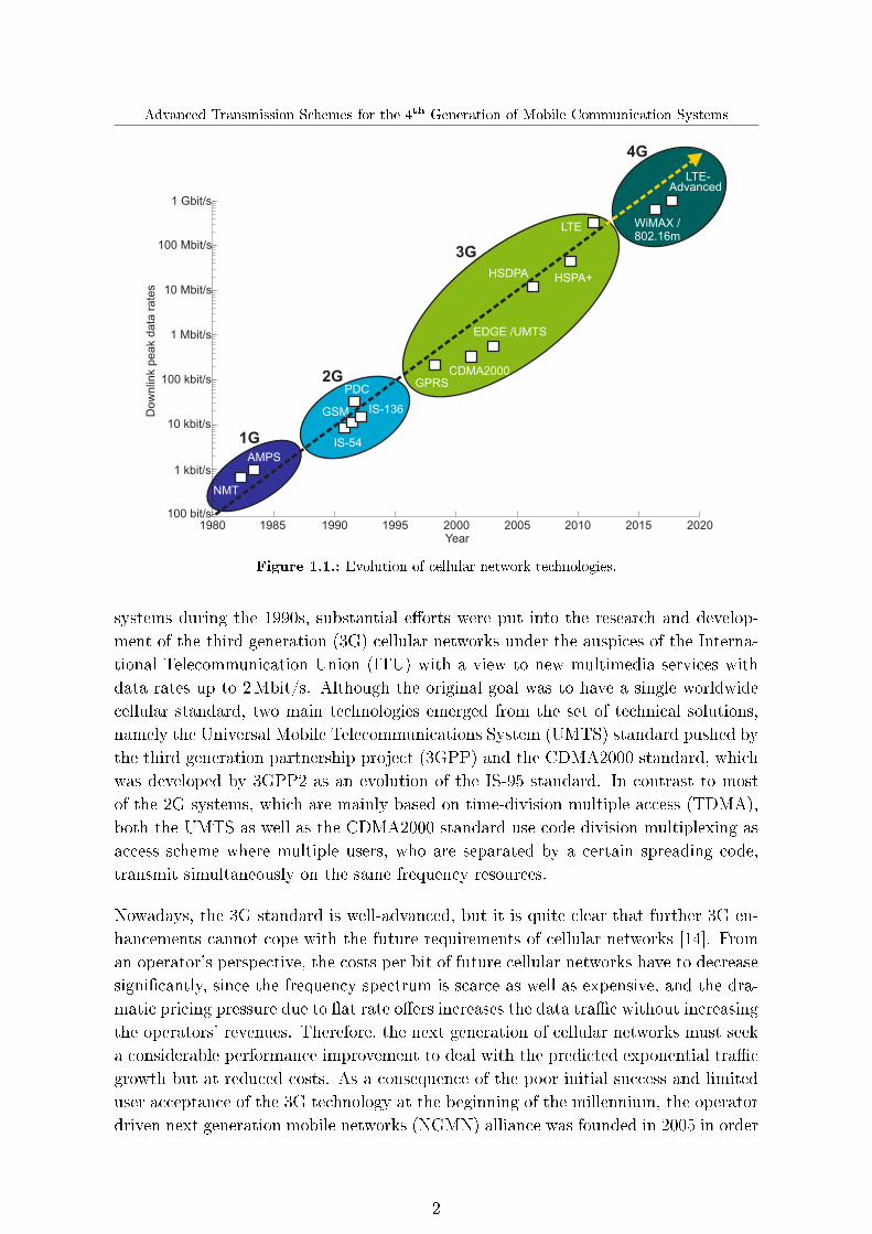
In 1895, wireless communications, one of today's fastest growing segments of the com-munications industry in the �eld of mobile broadband services, took its origin whenMarconi demonstrated the �rst wireless transmission of telegraph messages. Since then,wireless technologies have been constantly evolving, in particular wireless cellular net-works as shown in Fig. 1.1 [83]. The concept of cellular systems was developed byresearchers at the AT&T Bell Laboratories in order to solve the capacity problems ofthe early mobile communication systems [70]. In contrast to the �rst mobile commu-nication systems, where only one central base station (BS) covered the entire coveragearea, cellular systems divide the coverage area into non-overlapping cells each operatingwith its own BS. By exploiting the fact that the power of a transmitted signal falls o�with distance, the same frequencies can be reused in di�erent cells without introducingsevere inter-cell interference. As a consequence, the capacity substantially increasesdue to the e�cient utilization of the frequency spectrum.
The �rst cellular network was established in Japan by Nippon Telephone and Tele-graph (NTT) in 1979 [77]. Shortly after the commercial launch of the cellular networkin Japan, various cellular networks came into being worldwide such as the AdvancedMobile Phone System (AMPS) in the USA, the C-450 in Germany or the Nordic MobileTelephone (NMT) in the Scandinavian countries [83]. While all these independentlydeveloped systems�also known as the �rst generation (1G) of cellular networks�werebased on analog radio technology, the second generation (2G) represented a majorparadigm shift, since the analog technology was replaced by the digital one. Thisdigital revolution in mobile communications improved not only the capacity of cellu-lar networks, but also reduced the hardware costs and led to an exponential marketgrowth of mobile phones and to an increasing demand for mobile access to all typesof communication services, exceeding even the most optimistic expectations. However,the initial 2G cellular systems�such as the Global System for Mobile Communica-tions (GSM) in Europe, the interim standard (IS)-54, IS-95 and IS-136 in the USA andthe Personal Digital Cellular (PDC) in Japan�were only able to provide su�cient bitrates for voice services and rudimentary data services such as text messaging. There-fore, the 2G standards had been constantly improved since their launch in the early1990s. As an example, with the extensions General Packet Radio Service (GPRS) andEnhanced Data Rates for GSM Evolution (EDGE), the downlink peak data rate of theGSM standard was boosted from 9.6 kbit/s up to 384 kbit/s.
In parallel with the widespread deployment and evolution of 2G mobile communication
1
Advanced Transmission Schemes for the 4th Generation of Mobile Communication Systems
NMT
GSM
IS-54
PDC
IS-136
GPRS
EDGE /UMTS
HSDPA HSPA+
LTE
CDMA2000
4G
3G
2G
1G
100 bit/s
1 kbit/s
10 kbit/s
100 kbit/s
1 Mbit/s
10 Mbit/s
100 Mbit/s
1 Gbit/s
Dow
nlin
k p
eak d
ata
rate
s
LTE-
WiMAX /802.16m
AMPS
1980 1985 1990 1995 2000Year
2005 2010 2015 2020
Advanced
Figure 1.1.: Evolution of cellular network technologies.
systems during the 1990s, substantial e�orts were put into the research and develop-ment of the third generation (3G) cellular networks under the auspices of the Interna-tional Telecommunication Union (ITU) with a view to new multimedia services withdata rates up to 2Mbit/s. Although the original goal was to have a single worldwidecellular standard, two main technologies emerged from the set of technical solutions,namely the Universal Mobile Telecommunications System (UMTS) standard pushed bythe third generation partnership project (3GPP) and the CDMA2000 standard, whichwas developed by 3GPP2 as an evolution of the IS-95 standard. In contrast to mostof the 2G systems, which are mainly based on time-division multiple access (TDMA),both the UMTS as well as the CDMA2000 standard use code-division multiplexing asaccess scheme where multiple users, who are separated by a certain spreading code,transmit simultaneously on the same frequency resources.
Nowadays, the 3G standard is well-advanced, but it is quite clear that further 3G en-hancements cannot cope with the future requirements of cellular networks [14]. Froman operator's perspective, the costs per bit of future cellular networks have to decreasesigni�cantly, since the frequency spectrum is scarce as well as expensive, and the dra-matic pricing pressure due to �at rate o�ers increases the data tra�c without increasingthe operators' revenues. Therefore, the next generation of cellular networks must seeka considerable performance improvement to deal with the predicted exponential tra�cgrowth but at reduced costs. As a consequence of the poor initial success and limiteduser acceptance of the 3G technology at the beginning of the millennium, the operatordriven next generation mobile networks (NGMN) alliance was founded in 2005 in order
2

Chapter 1. Introduction
to specify the requirements of future cellular networks. A step forward to NGMN isthe Long Term Evolution (LTE) of UMTS, which was already initiated in 2004 andselected as �rst NGMN technology in 2008. LTE can be seen as a fully packet-switchedmulti-service air interface, which substantially improves the spectral e�ciency and theend-user throughput, thus is leading to a new user experience while reducing latencyand costs compared to previous cellular systems [3, 11, 49]. The LTE key technolo-gies for providing peak data rates exceeding 300Mbit/s in the downlink and 75Mbit/sin the uplink include orthogonal frequency division multiple access (OFDMA) in thedownlink and single-carrier frequency division multiplex access (SC-FDMA) in the up-link, various open and closed loop multiple-input multiple-output (MIMO) transmissionschemes, frequency-selective scheduling, adaptive modulation and coding based on avery short transmission time interval (TTI) of only 1ms, as well as scalable systembandwidths allowing �exible frequency spectrum allocations.
Recently, the ITU de�ned the International Mobile Telecommunications � Advanced(IMT-A) requirements for the fourth generation (4G) of cellular networks, and twoproposals currently being evaluated are based on the 802.16m standard�also knownas Worldwide Interoperability for Microwave Access (WiMAX)�as well as on the LongTerm Evolution � Advanced (LTE-A) standard. LTE-A represents the smooth evolu-tion of the LTE standard, aiming at peak data rates up to 1Gbit/s in the downlink and500Mbit/s in the uplink at an expanded bandwidth of 100MHz [78, 96]. In order toful�ll these ambitious targets, more sophisticated algorithms and innovative conceptsare essential, such as wider bandwidths through carrier aggregation, advanced multi-user (MU)-MIMO schemes, or various coordinated multipoint (CoMP) techniques [91].
In this thesis we analyze new promising concepts and schemes for the 4G of cellularnetworks. While the analysis of the theoretical limits of some of these concepts ingeneral and the performance of certain schemes applied to rather simpli�ed multi-cellsystems in particular have attracted a lot of research attention during the past fewyears (see for example [53, 55, 68, 94, 103]), a realistic and comprehensive evaluation ofthe gains that may be achieved with such schemes in real-world cellular systems, stillrepresents a largely untouched yet essential research area. As an important step in thisdirection, the analysis of the proposed transmission schemes in this thesis is based on acellular network model, which considers all relevant aspects of a real system to allow arealistic assessment of the achievable performance. Although we focus on a LTE-basedsystem in this thesis, the schemes thus introduced may be also adapted to other 4Gsystems.
The remainder of this thesis is organized as follows: In Chapter 2 the consideredLTE-based cellular system model is de�ned, which comprises not only the physicallayer but also important features of the medium access control (MAC) layer such asthe hybrid automatic repeat request (HARQ) protocol, resource scheduling as well asadaptive transmission, including link adaptation and transmission scheme selection.Furthermore, the frequency-selective and time-variant MIMO channel model based on
3

Advanced Transmission Schemes for the 4th Generation of Mobile Communication Systems
the 3GPP spatial channel model (SCM) is brie�y outlined together with the appliedpath-loss and shadowing model. Finally, this chapter also introduces the link-to-systeminterface, which provides a channel coding model to estimate the link level performanceat simulation run time, i.e. block error probabilities are generated that indicate whethera transmitted transport block is decoded erroneously or not.
Fundamental improvements in scheduling and feedback methods are introduced inChapter 3. Apart from di�erent resource scheduling schemes, two novel low-rate feed-back methods based on channel quality information (CQI) as well as on channel stateinformation (CSI) are evaluated. While the CQI feedback method is in line with theLTE Release 8 standard, the proposed CSI method represents a major shift in the feed-back paradigm compared to LTE Release 8. However, such sophisticated CSI feedbackmethods are currently being discussed for future mobile communication systems, suchas LTE-A, since such methods will be indispensable for realizing enhanced MU-MIMOand CoMP schemes in practice. Moreover, the impact of di�erent receiver types, HARQretransmissions, as well as uplink power control on the system performance is studiedfor the considered LTE-based system, which will be used as a reference for the proposedadvanced transmission schemes in Chapter 4 and Chapter 5.
In Chapter 4, enhanced MU-MIMO schemes with CQI as well as CSI feedback areproposed for the downlink, where multiple UEs might be served simultaneously on thesame frequency resources by means of proper precoding techniques, thus allowing fora more e�cient usage of the available frequency spectrum. In order to facilitate afair performance comparison between both schemes, approximately the same numberof feedback bits are used for both feedback methods, and an evaluation is made todemonstrate which method performs better in the considered scenario for various cases.This chapter also shows that signi�cant performance gains may be realized with bothproposed schemes compared to conventional LTE Release 8 networks without MU-MIMO support.
Various novel CoMP techniques for the uplink are studied in Chapter 5, where adjacentBSs cooperate with each other in order to mitigate the e�ects of inter-cell interference.In particular, di�erent interference coordination schemes are proposed, where di�erentBSs cooperate with each other in order to control and account for the inter-cell in-terference up to the case, where the resource allocation in di�erent cells is performedjointly by a central scheduling unit. Furthermore, we present a novel approach forcooperation-based interference prediction through which the link adaptation can besigni�cantly improved, as well as various cooperative detection methods where the sig-nals received by multiple cooperating BSs are taken into account. We demonstrate thatthe proposed CoMP methods yield a great potential for realizing a considerable increasein spectral e�ciency at reasonable complexity and backhaul load: hence, represent veryattractive options for future mobile communication systems, such as LTE-A.
A summary of the major achievements of this thesis as well as an outlook on futurework are given in Chapter 6.
4

Chapter 2. Cellular System Modeling
2. Cellular System Modeling
In this chapter we introduce the system model which will provide the foundation forthe analysis and evaluation of the investigated transmission schemes in this thesis.This system model considers a realistic interference-limited cellular network based onthe mobile communications standard LTE Release 8, recently �nalized by 3GPP [3,5].It includes all relevant features as well as practical constraints of a real system, suchas radio resource scheduling, HARQ protocol, adaptive MIMO transmission, signal-ing delays as well as imperfect feedback information. Fig. 2.1 exemplarily shows themain functionalities and most important features of the system model for the downlinktransmission between a certain user equipment (UE) and its serving BS. Note that forsimplicity the uplink system model is not considered here, since it generally includesthe same functionalities and features as the illustrated downlink model.
As shown in Fig. 2.1, each information bit stream to be sent to a certain UE is �rstencoded for forward error correction at the BS side. To this end, the channel coderinserts redundant bits into the information bit stream in order to allow bit errors intro-duced by the transmission over the wireless channel to be either detected or correctedby a decoder at the receiver side. In order to reduce the computational complexity, thechannel coding is abstracted by a link-to-system interface, which will be outlined indetail in Section 2.4. As indicated in Fig. 2.1, the code rate, i.e. the ratio between thenumber of information bits to the number of coded bits, is chosen by the MAC layerdepending on the radio link conditions. Each of the resulting coded bit streams is thenunited to a certain block of bits, also often referred to as transport block, whose size isde�ned by the MAC layer. The corresponding bits of these transport blocks are mappedto a symbol constellation, which is used to modulate the carrier signal. In this regard,the BS can choose between several modulation schemes, namely QPSK, 16QAM and64QAM, in order to accurately adapt the transmission format to the current channelconditions. Having determined the modulation and coding scheme (MCS) for eachtransport block, the respective data symbols of the transport blocks are then allocatedto the spatial layers, which in turn are mapped to the transmit antenna ports of theBS by means of a precoding matrix according to the selected transmission mode [3].It should be noted that the number of transport blocks is always less than or equal tothe number of spatial layers, which in turn is always less than or equal to the numberof transmit antenna ports. Finally, each data symbol is allocated to a certain radioresource element determined during the scheduling process and the pilot and controlchannel information are added to their prede�ned radio resources as well, before in alast step the corresponding orthogonal frequency division multiplex (OFDM) signals
5

Advanced Transmission Schemes for the 4th Generation of Mobile Communication Systems
Link adaptation
Resourcemapper
Precoding
OFDMmodulation
Resourcemapper
Modulationmapper
Modulationmapper
Channelcoding
Channelcoding
Bit stream
Layermapper
OFDMmodulation
Physical layer
SchedulingHARQ MCS selectionTransmission
scheme selection
Data streams Spatial layers
UE feedbackinformation
Control channelinformation
MAC layer
Base station
UE
Wireless channel
Layerdemapper
Resourcedemapper
OFDMdemodulation
OFDMdemodulation
Receiveantennas
Equalization
Physical layerData streamsSpatial layers
Resourcedemapper
Link-to-systemlevel
interface
Block errorprobability
Transmitantennas
Bit stream
UE
Block errorprobability
Figure 2.1.: Overview of the cellular system model for downlink transmission.
are generated and transmitted over the wireless channel.
At the UE side, standard MIMO receivers might be used to equalize the receivedsignals. Having determined the data streams after the layer demapping, the link levelperformance is accurately estimated by means of a link-to-system interface, which mapsthe determined signal-to-interference-plus-noise ratio (SINR) to a corresponding blockerror rate (BLER). Furthermore, the UEs periodically generate feedback informationabout the current downlink channel quality and send this information back to theirserving BS during the upcoming uplink transmission in order to facilitate channel-dependent scheduling, link adaptation, and transmission scheme selection.
The event-driven simulation chain described above is performed for each TTI duringa prede�ned number of scenarios, also known as so-called Monte Carlo drops. At thebeginning of each drop, a number of UEs is distributed on the cellular network areaaccording to a uniform distribution. The cellular network layout corresponds to a
6

Chapter 2. Cellular System Modeling
standard hexagonal grid with 19 BS sites and three-fold sectorization, and we makeuse of the wrap-around technique in order to avoid any border e�ects (cf. [1] andAppendix A). During each drop, the positions of the UEs and hence the path-loss andshadowing are kept constant, while the channel impulse response is time-variant andtherefore calculated in each TTI. The simulation methodology, as well as all relevantsimulation parameters, are summarized in Appendix A.
In the following sections the modeling of the mobile radio channel as well as the mostimportant features of the physical and MAC layer are described in more detail. Fur-thermore, we will provide the reader with some key assumptions and important systemlevel simulation parameters.
2.1. MIMO wireless channel
A realistic modeling of the mobile radio channel is essential for an accurate performanceevaluation of cellular networks, in particular for obtaining meaningful values for thekey performance indicators such as the spectral e�ciency or the cell-edge UE through-put. A profound understanding of propagation characteristics is therefore necessary toproperly describe the small- and large-scale propagation e�ects that occur during thesignal transmission [43]. Large-scale propagation e�ects such as path-loss as well asshadowing are causing variations in the received signal strength over relatively largedistances. While the path-loss indicates the attenuation of the signal strength withthe distance, shadowing is caused by obstacles in the propagation path that attenuatethe signal through absorption, re�ection, scattering or di�raction. Clearly, due to theUE movement some propagation paths will disappear, while other new ones appear.This, however, results in a slow variation of the received signal strength, which is oftenreferred to as slow or shadow fading.
In contrast to the large-scale propagation e�ects, small-scale e�ects such as multi-pathpropagation occurs over very short distances in the order of the signal wavelength. Dueto multi-path propagation the transmitted signal arrives via various ways at the re-ceiver. As a result, the received signal predominantly or exclusively consists of multiplepartly re�ected, di�racted or scattered components. Every multi-path component hasits own time delay and each of them accounts for the channel delay spread τDS, whichmay result in a signi�cant distortion of the received signal. The channel delay spreadis de�ned as the time delay between the arrival of the �rst and the last received signalcomponent. If the channel delay spread is larger than the symbol period τDS > Tsymbol,a long delayed symbol may interfere with a subsequent symbol arriving at the receivervia a more direct path with a short delay, resulting in inter-symbol interference (ISI).In the frequency domain this corresponds to a frequency-selective channel since the co-herence bandwidth�de�ned as the frequency range for which the transfer function canbe considered as constant�is smaller than the signal bandwidth. On the other hand,
7

Advanced Transmission Schemes for the 4th Generation of Mobile Communication Systems
if the channel delay spread is small compared to the symbol period, i.e. τDS < Tsymbol,the channel is said to be frequency-�at. Multi-carrier systems, such as OFDM (cf. [102]and Section 2.2.1), make use of this property by transmitting the symbols in parallelstreams: hence the symbol period becomes signi�cantly longer than the channel delayspread.
However, the instantaneous radio channel quality is not only varying in frequency, butalso in time, due to the movement of the UEs as well as due to moving objects inthe immediate vicinity. Hence, the location of the re�ectors in the transmission pathsis rapidly changing, leading to di�erent amplitudes, delays and number of multi-pathcomponents of each transmitted wave. This, in turn, results in a constructive anddestructive superposition of the arriving waves, which gives rise to fast fading of thereceived signal strength.
In addition, in the case of multi-antenna systems it is especially important to accu-rately model the correlation between the signals of the di�erent antenna elements,since this considerably impacts the selection of the preferred single-user (SU)- or MU-MIMO transmission schemes and their performance. Therefore, a realistic channelmodel has to address not only the instantaneous time and frequency characteristicsbut also the spatial characteristics of a MIMO channel. In recent years, more andmore sophisticated models for MIMO channels have been proposed, and one can dis-tinguish between two basic approaches, namely the physical as well as the analyticalMIMO channel models [10]. While the physical models explicitly account for all wavepropagation parameters such as complex amplitude, direction of departure and arrival,delay, etc. in order to accurately reproduce the radio propagation, the analytical chan-nel models characterize the impulse response of the channel between the individualtransmit and receive antennas in an analytical way without modeling explicitly thewave propagation. Within this work, we focus on a physical channel model, presentingin particular in the following a geometry-based stochastic model for frequency-selectiveand time-variant MIMO radio channels.
2.1.1. The 3GPP spatial channel model
We make use of the 3GPP SCM and its extension also known as spatial channel model� extension (SCME) to accurately model the multi-path fading [2, 12, 20]. Both theSCM and the SCME are based on a ray-modeling technique as shown in Fig. 2.2. Eachpath is modeled by a number of subpaths as a sum-of-sinusoids, each representingindividual plane waves received by the antenna array. The subpaths di�er in theangles of arrival and departure, which induce static phase shifts between the respectiveantenna elements of the transmitter and receiver. By taking a certain UE velocity intoaccount, additional dynamic phase shifts occur at the UE side.
The large-scale parameters, such as the delay spread, angular spread, and angle of ar-rival and departure, are generated as realizations of random variables from appropriate
8

Chapter 2. Cellular System Modeling
Reflection cluster k
Subpath l of path k
Path k
θBS
θAOD,k,l
BS antenna array
UE antenna array
θUE
θAOA,k,l
θv
UE directionof traval
UE array broadside
BS array broadside
Figure 2.2.: Ray-based channel modeling according to the SCM [20].
probability distributions according to measured environment statistics [2, 20]. Thesestatistics and the corresponding environment parameters depend on the selected prop-agation environment, where the considered SCM, for example, is able to distinguishbetween three di�erent environments, namely Suburban, Urban Macro as well as Ur-ban Micro. Within this thesis, we focus on the Urban Marco scenario correspondingto the situation where the BSs are placed on high rooftops within a dense urban area,resulting in moderate to high angular as well as delay spreads. Furthermore, the large-scale parameters are autocorrelated, i.e. closely located UEs have a higher probabilityof experiencing similar large-scale parameters than the ones being far apart from eachother.
Let us �rst of all consider the MIMO channel between a certain transmitter and receiver,both equipped with multiple antennas. The corresponding equivalent baseband channelmatrix H (t, τ) ∈ C[N×M ] representing the MIMO channel may be expressed as
H (t, τ) =
h1,1 (t, τ) h1,2 (t, τ) · · · h1,M (t, τ)
h2,1 (t, τ) h2,2 (t, τ) · · · h2,M (t, τ)...
.... . .
...hN,1 (t, τ) hN,2 (t, τ) · · · hN,M (t, τ)
, (2.1)
where N and M denote the number of receive and transmit antenna elements, respec-tively, and where hµ,ν (t, τ) represents the time-variant impulse response between theν-th transmit and the µ-th receive antenna element, which is a function of the dis-crete time t and the time delay τ . As mentioned already before, the impulse responsehµ,ν (t, τ) is the superposition of all individual multi-path components and hence isgiven by
hµ,ν (t, τ) =
Kpath∑k=1
hµ,ν,k (t) δ (τ − τk) , (2.2)
9

Advanced Transmission Schemes for the 4th Generation of Mobile Communication Systems
where Kpath denotes the number of paths. In the following, we explicitly outline thecalculation of the downlink channel impulse response. The uplink channel impulseresponse can be determined in a similar way and hence is not further considered.The multi-path component hµ,ν,k (t) of the downlink channel impulse response may beexpressed as [20]
hµ,ν,k (t) =
√Pk Psf PplKsubpath
·Ksubpath∑l=1
(√Gbs
(θAoD,k,l
)ejdνq sin(θAoD,k,l)+jφk,l
·√Gue
(θAoA,k,l
)ejdµq sin(θAoA,k,l)
· ejq ‖v‖ cos(θAoA,k,l−θv)t),
(2.3)
where
Pk denotes the normalized power of the k-th path, so that the totalaverage power for all Kpath paths is equal to unity;
Psf denotes the shadow fading loss;Ppl denotes the path-loss;Ksubpath denotes the number of subpaths;θAoA,k,l denotes the angle of arrival for the l-th subpath of the k-th path;θAoD,k,l denotes the angle of departure for the l-th subpath of the k-th path;φk,l denotes the phase of the l-th subpath of the k-th path;Gbs (θ) denotes the antenna gain of the BS;Gue (θ) denotes the antenna gain of the UE;dν denotes the distance between the transmit antenna element ν to the
reference (ν = 1);dµ denotes the distance between the receive antenna element µ to the
reference (µ = 1);q denotes the wavenumber de�ned by 2π/λ, where the wavelength λ
is given by c/fc, with c as the speed of light and fc as the carrierfrequency;
v denotes the UE velocity vector;θv �nally represents the angle of the UE velocity vector.
Furthermore, we assume directional antennas at the BS side with a standard two-dimensional antenna pattern as speci�ed in [2], where the angle-dependent attenuationA (θ) in dB is given by
A (θ)∣∣dB
= −min
{12
(θ
θ3dB
)2
, Afb
}, −180◦ ≤ θ < 180◦ (2.4)
10

Chapter 2. Cellular System Modeling
with θ as the angle relative to the boresight of the antenna, θ3dB as the half-powerbeamwidth, and Afb as the front-to-back power ratio. Thus, with the expression in(2.4) the BS antenna gain Gbs (θ) in dB can be expressed as
Gbs (θ)∣∣dB
= Gbs,max
∣∣dBi
+ A(θ)∣∣dB, (2.5)
where Gbs,max indicates the maximal BS antenna gain. Throughout this thesis, weassume omni-directional antennas at the UE side and hence the UE antenna gainGue (θ) in (2.3) simpli�es to
Gue (θ) = 1. (2.6)
Multi-carrier systems subdivide the frequency-selective wideband channel into a num-ber of subchannels also known as subcarriers (cf. Section 2.2.1). Ideally, these narrow-band subcarriers are non-frequency-selective, thus the channel delay spread becomessmaller than the symbol period. Then, the general MIMO input-output relation for acertain subcarrier
y (t) = H (t, τ) ∗ s (t) + i (t) + n (t) (2.7)
simpli�es to
y (t) = H (t) · s (t) + i (t) + n (t) , (2.8)
with s (t) ∈ C[M×1] as the transmitted signal, i (t) ∈ C[N×1] and n (t) ∈ C[N×1] as theinter-cell interference and noise, respectively. For notational convenience we will omitin the following the index for the discrete time. Note that (2.7) and (2.8) hold for theequivalent baseband system.
2.1.2. Pathloss model
For determining the path-loss Ppl, which is applied to all Kpath paths of the channelimpulse response in (2.3), we make use of the well-known COST231 path-loss modelbased on the Hata urban propagation model [28]. The path-loss Ppl in dB is thereforegiven by
Ppl∣∣dB
=
44.9− 6.55 log10
(hbs|m1m
) log10
(dbs,ue
∣∣km
1 km
)+ 45.5 + 0.7
hue|m1m
+
(35.46− 1.1
hue|m1m
)log10
(fc|MHz
1MHz
)− 13.82 log10
(hbs|m1m
)+ C,
(2.9)
with hbs and hue as the antenna heights of the BS and UE, respectively, dbs,ue as thedistance between the UE and its serving BS, fc as the carrier frequency and C as aconstant factor, which is equal to 3 dB for the considered Urban Macro environment.
11

Advanced Transmission Schemes for the 4th Generation of Mobile Communication Systems
2.1.3. Shadow fading model
In this section we brie�y outline the shadowing model and its correlation properties.The correlation of the shadow fading plays an important role in the realistic modelingof cellular networks due to its considerable impact on the system performance. In thisregard, one has to distinguish between two fundamental correlation e�ects. On the onehand, the cross-correlation of the shadowing components between a certain UE anddi�erent BS sectors or sites is an important aspect that has to be taken into account.On the other hand, the shadow fading values have to be spatially correlated due tothe fact that terrain properties and obstacles in the vicinity of a UE neither changeabruptly nor disappear. Thus, location-based shadowing values are required to ensurethat closely located UEs experience a similar signal attenuation due to the shadowinge�ect. In the following, the applied method for generating two-dimensional shadowingvalues with appropriate spatial and cross-correlation statistics is outlined.
In general, the shadow fading process ζsf is characterized by a zero mean Gaussian ran-dom variable with variance σ2
sf in the logarithmic domain [97]. Hence, the probabilitydensity function (PDF) is given by
p (ζsf) =1√
2π σsfe−
ζ2sf
2σ2sf . (2.10)
Let us assume a two-dimensional cellular network layout de�ned by a certain sizewhich is subdivided into squares de�ned by the applied resolution (cf. Appendix A).
Then, the corresponding location-based shadowing matrix Zsf ∈ R[Xgrid×Ygrid] may beexpressed as
Zsf =
ζ1,1 ζ1,2 · · · ζ1,Ygridζ2,1 ζ2,2 · · · ζ2,Ygrid...
.... . .
...ζXgrid,1 ζXgrid,2 · · · ζXgrid,Ygrid
, (2.11)
where Xgrid and Ygrid indicate the number of two-dimensional grid points. Thus, eachgrid point indicates a certain square of the cellular network layout. Each square in turnis represented in (2.11) by a random variable ζ distributed according to (2.10). Clearly,the number of squares and hence shadowing variables depend on the network layoutsize as well as on the applied resolution. Based on the correlation model proposedin [45], which is suitable for suburban and urban environments, the elements of theshadowing matrix in (2.11) can be spatially correlated. However, [45] only provides aone-dimensional form for the shadowing autocorrelation, which can be simply extendedto the two-dimensional case by
R (∆x,∆y) = e−√
∆x2+∆y2
dcorrln 2, (2.12)
where ∆x and ∆y denote the increments corresponding to the respective coordinateor equivalently the resolution of the cellular network layout, and dcorr indicates the
12
Chapter 2. Cellular System Modeling
0 500 1000x [m]
1500 2000
-20dB
-10dB
0dB
10dB
20dB
30dB
40dB
0
500
1000
1500
2000
2500y [m
]
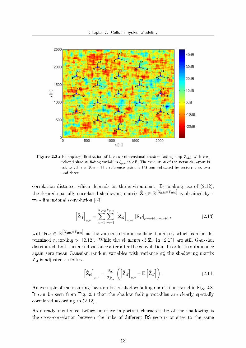
Figure 2.3.: Exemplary illustration of the two-dimensional shadow fading map Zsf,1 with cor-
related shadow fading variables ζµ,ν in dB. The resolution of the network layout is
set to 20m × 20m. The reference point is BS one indicated by sectors one, two
and three.
correlation distance, which depends on the environment. By making use of (2.12),
the desired spatially correlated shadowing matrix Zsf ∈ R[Xgrid×Ygrid] is obtained by atwo-dimensional convolution [33]
[Zsf
]µ,ν
=
Xgrid∑n=1
Ygrid∑m=1
[Zsf
]n,m
[Rsf]µ−n+1,ν−m+1 , (2.13)
with Rsf ∈ R[Xgrid×Ygrid] as the autocorrelation coe�cient matrix, which can be de-termined according to (2.12). While the elements of Zsf in (2.13) are still Gaussiandistributed, both mean and variance alter after the convolution. In order to obtain onceagain zero mean Gaussian random variables with variance σ2
sf the shadowing matrixZsf is adjusted as follows[
Zsf
]µ,ν
=σsfσZsf
([Zsf
]µ,ν− E
[Zsf
]). (2.14)
An example of the resulting location-based shadow fading map is illustrated in Fig. 2.3.It can be seen from Fig. 2.3 that the shadow fading variables are clearly spatiallycorrelated according to (2.12).
As already mentioned before, another important characteristic of the shadowing isthe cross-correlation between the links of di�erent BS sectors or sites to the same
13

Advanced Transmission Schemes for the 4th Generation of Mobile Communication Systems
location. It should be noted that we do not distinguish in the following between sector-to-sector or site-to-site cross-correlation since the cross-correlation between BS sites orbetween their respective sectors is approximately identical. We particularly consideran approach similar to the one presented in [58] to accurately model the BS site-to-site cross-correlation. The basic idea of this approach is to split the Gaussian shadowfading process into two independent random components. While the �rst part is thesame for all BS sites, the second part represents a BS-dependent component. Thus,the location-based shadowing with both spatial as well as cross-correlation propertiescan be written as
Zsf,k =√ρsite Zsf,0 +
√1− ρsite Zsf,k k = 1, . . . , Kbs , (2.15)
where Zsf,0 as well as Zsf,k can be determined according to (2.14). Furthermore, ρsitedenotes the correlation coe�cient between the propagation paths of a certain UE totwo di�erent BS sites, and Kbs indicates the number of BSs located in the deploymentarea.
2.2. Physical layer
The physical layer provides the framework for transmitting both data and controlinformation between a UE and its serving BS. The transmission in the downlink as wellas in the uplink is realized by means of several physical channels in order to e�cientlyexploit the available frequency spectrum and to support e�ective multiplexing betweendata and control signaling [86]. While the physical control channels basically conveyimportant signaling and control information with a rather low MCS for achieving arobust transmission with minimal errors, the physical shared channels are designed fortransmitting data and multimedia information with very high data rates and hencethese channels support much higher MCSs compared to the physical control channels.
The LTE physical layer provides a high level of �exibility. Apart from being able tooperate either in time division duplexing (TDD) or frequency division duplexing (FDD)mode, LTE additionally supports a variety of di�erent frequency bandwidths from1.4MHz up to 20MHz. This allows operators to use the already existing as well asnew frequency bands more e�ciently and simpli�es the deployment of LTE. Note thatwe assume for our system-level simulations a LTE-based system operating in FDDmode with a system bandwidth of 10MHz (cf. Appendix A).
In general, cellular networks are multi-user communication systems, hence the samesystem resources, such as time, frequency and space, are shared by di�erent UEs. Asa consequence, the signals of these UEs have to be allocated by so-called multipleaccess schemes before transmitting them over the physical channels. The multipleaccess schemes selected for LTE are OFDMA in the downlink and SC-FDMA in theuplink. These schemes play an important role in future physical layer frameworks and
14

Chapter 2. Cellular System Modeling
are introduced below, together with the transmission frame structure, reference signalsand considered detection techniques.
2.2.1. Orthogonal frequency division multiple access
OFDM is one of the most popular multi-carrier schemes, which is already employed inmany systems both wired as well as wireless, such as Asymmetric Digital SubscriberLine (ADSL), Digital Video Broadcasting (DVB) or Wireless Local Area Network(WLAN). A reason why OFDM has also found its way as access scheme into the 4G ofcellular networks is, for example, the lower complexity of equalizers in the case of highdelay spread channels compared to single-carrier systems. Another important reasonis that the processing power of digital signal processors is constantly increasing, sincecellular systems based on OFDM were �rst proposed in 1985 [24], thus making OFDMhighly attractive for implementation nowadays.
In general, a conventional serial transmission of a high-rate data stream entails a shortsymbol period, which is often much smaller than the channel delay spread. This causesISI, where the received symbol over a given symbol period experiences interference fromother symbols that have been delayed due to the multi-path propagation. A standardapproach to countervail this e�ect is to employ a complex equalization mechanismat the receiver side. However, a far more e�ective approach with considerably lowerequalization complexity is multi-carrier modulation. The basic idea of multi-carriermodulation, and OFDM in particular, is to split a high-rate data stream into severalsub-streams with a much lower data rate. These sub-streams are sent over di�erentsubcarriers, so that the symbol duration on each subcarrier becomes signi�cantly longerthan the channel delay spread. As a result, the OFDM system is less sensitive to ISIthan a conventional serial system since the frequency-selective wideband channel issubdivided into a number of narrowband subcarriers, which are no longer subject tofrequency-selective fading. Thus, complex channel equalization mechanisms may beavoided. Furthermore, in the case of OFDM these subcarriers are overlapping butorthogonal. In this way, additional guard bands for separating the di�erent subcarriersare not required: this consequently increases the spectral e�ciency. However, therequired insertion of a guard interval mitigates the spectral e�ciency advantage.
In an OFDM system, the signal to be transmitted is de�ned in the frequency domain.Let us assume that a symbol stream is passed through a serial-to-parallel converter,whose output is the complex vector
Xk =[Xk [0] , Xk [1] , . . . , Xk [Q− 1]
]T, (2.16)
where k denotes the index of an OFDM symbol spanning Q subcarriers and (·)T isthe transpose operator. In order to generate the time domain signal, the discretefrequency components of the OFDM signal Xk are converted into time samples by
15

Advanced Transmission Schemes for the 4th Generation of Mobile Communication Systems
x[N-µ],...,x[N-1] x[0],x[1],...,x[N-µ-1] x[N-µ],...,x[N-1]
TCP TOS
Tsymbol
CP Original sequence
Figure 2.4.: OFDM CP insertion.
performing an inverse discrete Fourier transform (IDFT). The resulting time domainsignal xk =
[xk [0] , . . . , xk [N − 1]
]Tis determined by
xk [n] =1√N
N−1∑i=0
Xk [i] ej2πni/N , 0 ≤ n ≤ N − 1, (2.17)
where in the case that N > Q the unmodulated subcarriers are padded with zeros. Itshould be noted that in practice the IDFT and the discrete Fourier transform (DFT)are usually implemented using the respective fast Fourier transformation algorithms inorder to signi�cantly reduce the computational complexity.
A crucial step in the OFDM signal generation is the insertion of a guard interval inorder to assure that even a channel with a large delay spread does not cause ISI dueto the multi-path propagation. This is done in such a way that a so-called cyclicpre�x (CP) is inserted at the beginning of each OFDM symbol as shown in Fig. 2.4.The CP consists of the last µ samples of xk. Thus, after appending the CP the timedomain signal can be expressed as
xk =[xk [N − µ] , . . . , xk [N − 1] , xk [0] , . . . , xk [N − 1]
]T. (2.18)
Finally, xk is passed through a parallel-to-serial as well as through a digital-to-analogconverter and the resulting OFDM signal, which is up-converted to a certain carrierfrequency, is then transmitted over the wireless channel. At the receiver side the CP,which is a�ected by the ISI, can be discarded without any loss of the original infor-mation. However, the bene�ts of the CP come at the cost of a decrease in spectrale�ciency as well as an increase in signal power per bit, since the CP only consists ofredundant information. Having removed the CP, the reverse operations are performedto demodulate the OFDM signal, starting with a DFT in order to obtain the transmit-ted symbols in the frequency domain. Due to the inserted CP, the computation of thereceived samples leads to a circular symmetric convolution of the transmitted sampleswith the overall channel impulse response. This circular convolution in the time do-main is transformed at the receiver side by means of the DFT into a multiplication inthe frequency domain, which signi�cantly simpli�es the equalization procedure.
16

Chapter 2. Cellular System Modeling
15 30 45 60 75 90 105
−0.2
0
0.2
0.4
0.6
0.8
1
Frequency [kHz]
Am
plitu
de o
f rec
eive
d O
FD
M s
ubca
rrie
rsδδ: carrier frequency offset
DFT samplingpoints
Figure 2.5.: Illustration of the orthogonality loss between di�erent OFDM subcarriers due to
imperfect frequency separation.
Apart from all the advantages o�ered by OFDM, such as being able to transmitdata at high rates while avoiding ISI and inter-carrier interference (ICI) as well ascomputationally inexpensive subcarrier equalization, OFDM also has some signi�cantdisadvantages. One of the major drawbacks is that the amplitude variations of theOFDM modulated signal may be very high, leading to a high peak-to-average powerratio (PAPR) [102]. However, the linear operation of power ampli�ers is limited withina certain range. This, in turn, limits the peak power value not exceeding the linearoperation range in order to avoid signal distortions. Furthermore, it is shown in [102]that the maximum PAPR is approximately equal to the number of subcarriers, thusthe PAPR increases with increasing number of subcarriers. There are a number oftechniques to reduce the PAPR of OFDM signals, such as clipping of high signal valuesto a prede�ned level or special coding techniques [46].
Another drawback of OFDM is the high sensitivity to imperfect frequency separationof the subcarriers, resulting in ICI. The orthogonality condition of the subcarriers isbased on the assumption that transmitter and receiver operate with exactly the samefrequency reference. In practice, however, there is always a di�erence between thereference frequencies at the transmitter and receiver side due to mismatched oscillators,Doppler frequency shifts or timing synchronization errors. This frequency di�erence isoften referred to as carrier frequency o�set, which is shown as an example in Fig. 2.5.
In cellular networks, access schemes are used to allow the available radio resourcesto be shared among di�erent users at the same time. OFDM can be extended toOFDMA, where all subcarriers are not only allocated to a single UE, but where thesubcarriers are distributed to several UEs. Since the indication on which subcarriers acertain UE has been allocated causes a signi�cant signaling overhead, subcarriers areallocated in contiguous groups. In the case of LTE, the minimum resource unit for
17

Advanced Transmission Schemes for the 4th Generation of Mobile Communication Systems
subcarrier allocation is the so-called physical resource block (PRB), which consists of agroup of adjacent subcarriers and OFDM symbols (c.f. [3,49] and Section 2.2.3). Thus,LTE uses a combination of OFDMA and TDMA as access scheme. A further detailedexplanation of OFDMA can be found in [102].
Throughout this thesis we assume that the considered OFDMA scheme is ideal, i.e.the BSs and UEs are perfectly synchronized with each other in time and frequency andthe channel delay spread never exceeds the CP length. Thus, the considered OFDMAscheme neither su�ers from ICI nor from ISI.
2.2.2. Single-carrier frequency division multiple access
For the LTE uplink a modi�ed form of OFDMA is employed as access scheme, whichis often referred to as SC-FDMA or DFT-spread OFDMA [3,75]. The use of a single-carrier modulation in the uplink is motivated by the signi�cantly lower PAPR providedby SC-FDMA compared to OFDM. This is a crucial factor since in the uplink theUEs are generally power-limited, and hence power-e�cient transmission is essential inorder to increase coverage and to lower the power consumption. The basic principleof SC-FDMA is shown in Fig. 2.6. In order to overcome the problem of high envelope�uctuations in the transmitted signals as in the case of OFDM, SC-FDMA �rst appliesa Mk-point DFT to the modulated symbols transmitted by UE k. Before mappingeach of the output samples of the Mk-point DFT to the N available subcarriers, zerosare inserted to the output of the Mk-point DFT in order to match the DFT size tothe N -point IDFT of the OFDM modulator. In general, Mk is smaller than N andhence the output of the IDFT transforms the subcarrier amplitudes to a complex timedomain signal. This consequently leads to a signal with low power variations. Notethat if the DFT size Mk was equal to the IDFT size N , the DFT operation wouldcancel the IDFT of the OFDM modulator, resulting in a serial transmission of thedata symbols in the time domain.
However, the lower PAPR in the case of SC-FDMA comes at a cost of an increasedcomplexity and reduced �exibility in terms of resource allocation. There are two pos-sible methods for allocating the output of the DFT to the available subcarriers [75].On the one hand, the so-called localized mapping allocates a group of consecutive sub-carriers to each UE, as illustrated in Fig. 2.6. By contrast, the output of the DFT canbe also mapped to equally spaced subcarriers, which is often referred to as distributedmapping. While the distributed approach bene�ts from additional frequency diversitycompared to the localized approach, the latter one achieves MU diversity by assigningdi�erent adjacent PRBs to each UE depending on the current channel quality. Withinthis work, we always assume a localized mapping of subcarriers, because this is a cru-cial prerequisite for performing channel-dependent scheduling (cf. Section 2.3.1 andSection 3.2).
18

Chapter 2. Cellular System Modeling
M -point
DFTx
x , x ,...,x0 1 Mx-1Symbol tosubcarriermapping
N-pointIDFT
AddCP
UE x
M -point
DFTy
y , y ,...,y0 1 My-1Symbol tosubcarriermapping
N-pointIDFT
AddCP
UE y
Total bandwidthof N subcarriers
Localized bandwidthmapping
UE x UE y
UE x UE y
Total bandwidthof N subcarriers
M modulation
symbolsx
M modulation
symbolsy
Figure 2.6.: SC-FDMA signal generation and resource allocation for localized mapping.
2.2.3. Transmission frame structure
In LTE, both downlink and uplink transmissions are based upon a generic transmissionframe structure, which de�nes the organization of the radio resources in the time andfrequency domain [3]. This transmission frame structure is shown in Fig. 2.7 for FDDand it may be applied to either full- or half-duplex operation with respect to thetransmission and reception of the UEs. In contrast to full-duplex FDD, where theUEs are able to transmit and receive signals at the same time but on di�erent carrierfrequencies, UEs operating in a half-duplex FDD mode separate the transmission andreception not only in the frequency domain, but also in the time domain. Hence, half-duplex FDD can be seen as a hybrid combination of FDD and TDD [86]. Note thatthroughout this thesis a system operating in full-duplex FDD is assumed.
As shown in Fig. 2.7 the downlink and uplink transmissions are composed of radioframes with a duration of 10ms. A radio frame consists of 20 slots, each being 0.5mslong. Two consecutive slots in turn are de�ned as a subframe, whose duration isobviously 1ms. Depending on the subcarrier spacing as well as on whether a normalor an extended CP length is applied, a slot comprises either seven, six or three OFDMsymbols [3]. In the frequency domain, consecutive subcarriers are grouped in blocksof 180 kHz, where the number of consecutive subcarriers per block depends on thecon�gured subcarrier spacing. The minimum unit for radio resource allocation canbe described as a two-dimensional time-frequency grid that corresponds to one slotin the time domain and 180 kHz in the frequency domain. This resource unit is alsooften referred to as PRB and it is illustrated in more detail in Fig. 2.8. Apart fromthe time and frequency dimension, radio resources may be also allocated in the spatialdimension in the case of a multi-antenna system and hence for each antenna elementa corresponding resource grid is de�ned.
Clearly, the number of resource elements per PRB depends on the CP length due tothe increased overhead that comes with a longer CP duration. Furthermore, the totalnumber of available resource elements is restricted by the overall system bandwidth,which is scalable in the range of 1.25MHz up to 20MHz [86]. However, not all available
19

Advanced Transmission Schemes for the 4th Generation of Mobile Communication Systems
0 1 2 3 18 19
One radio frame, T = 10msframe
One slot, T = 0.5msslot
One subframe, T = 1mssubframe
Figure 2.7.: LTE transmission frame structure for FDD.
resource elements can be used for data transmission. Within the resource grid, someresource elements are reserved for synchronization, control as well as reference signals.This will be discussed in more detail in the following section.
2.2.4. Reference and control signaling
In order to establish and to sustain a communication link between a UE and its servingBS additional signaling is generally required apart from the conventional data trans-mission. Using the example of LTE, the important downlink and uplink reference andcontrol signals are outlined in more detail in the following. These are essential for en-abling coherent channel estimation, link adaptation, and channel-dependent scheduling.In this regard, we discuss the generation of these signals and how they are embeddedinto the resource grid shown in Fig. 2.8.
2.2.4.1. Reference signals
A crucial prerequisite for coherent detection is that the receiver is able to accuratelyestimate the channel. In contrast to non-coherent detection, where only the ampli-tude information is exploited, coherent detection makes use of both the amplitude andphase information of the transmitted signals. One method to e�ciently estimate thechannel coe�cients for coherent detection without causing unnecessary overhead is tospread known reference signals�also often referred to as pilot signals�onto the avail-able radio resources, as illustrated in Fig. 2.9 for the LTE downlink and uplink in thecase of a two-dimensional time-frequency resource grid. In the case of multi-antennatransmission, this resource grid is extended by a spatial dimension: hence, for eachtime-frequency resource grid corresponding to a certain antenna element, a di�erentreference signal pattern may be de�ned. In this way, the interference between referencesignals corresponding to di�erent antenna elements can be limited, facilitating an ac-curate estimation of the di�erent channel coe�cients. Note that these reference signalpatterns have been recently speci�ed in the LTE Release 8 only for the downlink [3].This is because multi-antenna transmission in the LTE uplink, although currently sub-ject to discussions, is not yet standardized. Furthermore, in order to keep the signaling
20

Chapter 2. Cellular System Modeling
K subcarrierssub
K subcarriersbandwidthT
slo
t
Resource element Physical resource block
Multiple antenna
elements
Figure 2.8.: LTE radio resource grid.
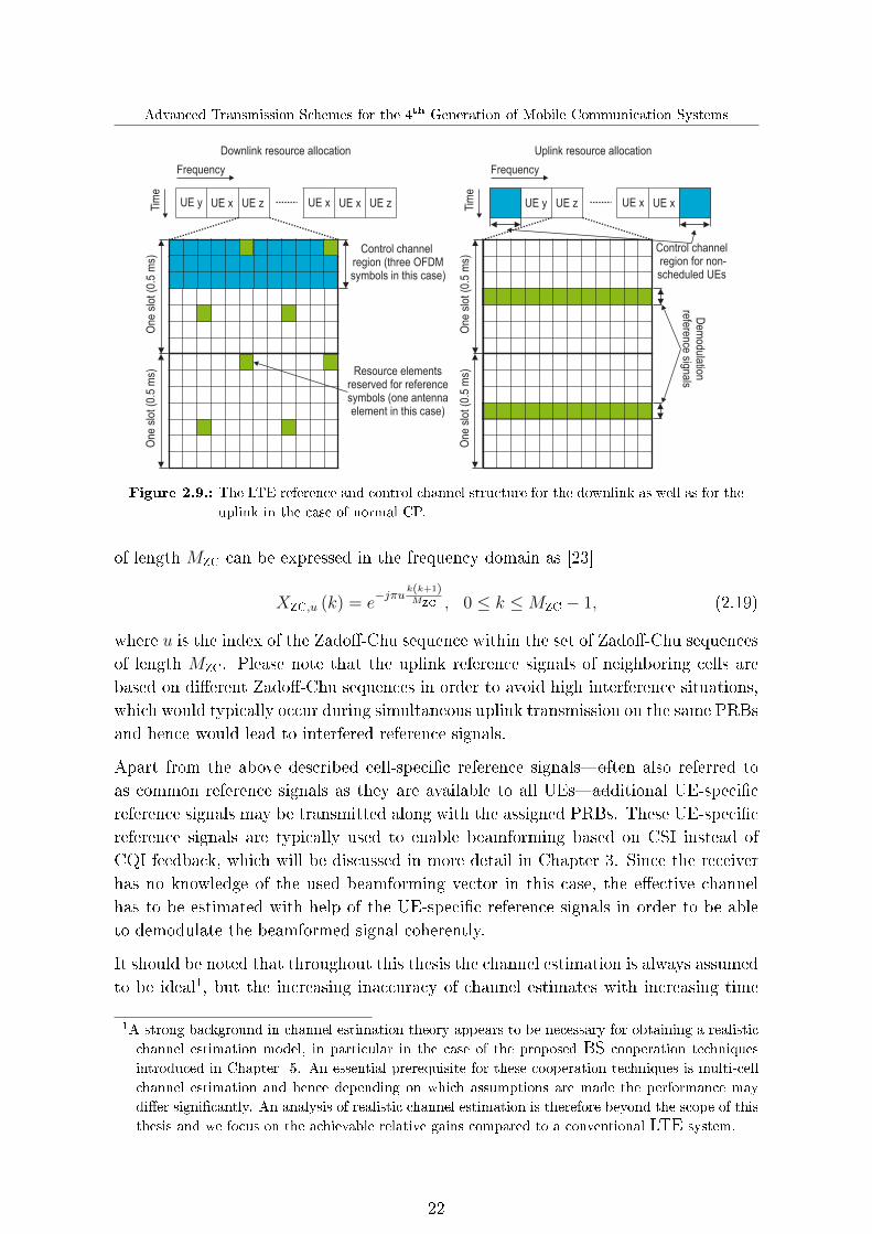
overhead limited only a few reference signals are embedded into the resource grid asillustrated in Fig. 2.9. Thus, the channel estimates for the data carrying resource ele-ments have to be obtained by interpolation. An optimal but high complexity channelestimation technique is based on the Wiener �lter interpolation [105], whereas furthertechniques providing a good trade-o� between complexity and accuracy can be foundin [72].
By comparing the LTE downlink and uplink reference signals in Fig. 2.9 it can be seenthat the arrangement of the uplink reference signals signi�cantly di�ers from the one ofthe downlink due to the di�erent access schemes. Consequently, instead of multiplexingthe reference signals in the frequency domain, the uplink reference signals have tobe time multiplexed [86]. Moreover, in the uplink two di�erent reference signals arerequired to obtain channel information at the BS side. On the one hand demodulationreference signals are sent along with the actual assigned PRBs for data transmissionin order to facilitate coherent detection, whereas additional sounding reference signalsare required to obtain channel estimates of those frequency bandwidth parts, which arenot associated with any uplink data transmission. In order to exploit the MU diversityin the case of frequency-selective scheduling, channel estimates of the UEs over thewhole frequency bandwidth are needed. While this can be simply accomplished in thedownlink by measuring the quality of the reference signals, which are automaticallytransmitted over the whole bandwidth, in the uplink the above mentioned soundingreference signals are required [3].
In contrast to the LTE downlink, where the reference signals are generated based on aGolden code to obtain the orthogonality between di�erent reference-symbol positionsand also between di�erent cells [79], the uplink demodulation and sounding referencesignals are based on Zado�-Chu sequences, which ful�ll the stringent requirements ofthe LTE uplink, i.e. constant amplitude for a low PAPR and good time-domain auto-correlation properties to enable accurate channel estimation. A Zado�-Chu sequence
21
Advanced Transmission Schemes for the 4th Generation of Mobile Communication Systems
Figure 2.9.: The LTE reference and control channel structure for the downlink as well as for the
uplink in the case of normal CP.
of length MZC can be expressed in the frequency domain as [23]
XZC,u (k) = e−jπu k(k+1)
MZC , 0 ≤ k ≤MZC − 1, (2.19)
where u is the index of the Zado�-Chu sequence within the set of Zado�-Chu sequencesof length MZC. Please note that the uplink reference signals of neighboring cells arebased on di�erent Zado�-Chu sequences in order to avoid high interference situations,which would typically occur during simultaneous uplink transmission on the same PRBsand hence would lead to interfered reference signals.
Apart from the above described cell-speci�c reference signals�often also referred toas common reference signals as they are available to all UEs�additional UE-speci�creference signals may be transmitted along with the assigned PRBs. These UE-speci�creference signals are typically used to enable beamforming based on CSI instead ofCQI feedback, which will be discussed in more detail in Chapter 3. Since the receiverhas no knowledge of the used beamforming vector in this case, the e�ective channelhas to be estimated with help of the UE-speci�c reference signals in order to be ableto demodulate the beamformed signal coherently.
It should be noted that throughout this thesis the channel estimation is always assumedto be ideal1, but the increasing inaccuracy of channel estimates with increasing time
1A strong background in channel estimation theory appears to be necessary for obtaining a realistic
channel estimation model, in particular in the case of the proposed BS cooperation techniques
introduced in Chapter 5. An essential prerequisite for these cooperation techniques is multi-cell
channel estimation and hence depending on which assumptions are made the performance may
di�er signi�cantly. An analysis of realistic channel estimation is therefore beyond the scope of this
thesis and we focus on the achievable relative gains compared to a conventional LTE system.
22
Chapter 2. Cellular System Modeling
due to the time-varying nature of the channel is taken into account as well as theloss in terms of spectral e�ciency due to the introduced reference and control signals.While the absolute values obtained in this way may be generally overly optimistic, theassumption of perfect channel estimation allows us to quantify the maximum possibleperformance gains under various di�erent conditions.
2.2.4.2. Control channel
In wireless communication systems, control channels are generally used for the trans-mission of control and con�guration information. In the case of LTE, the downlinkcontrol information contains scheduling messages together with the corresponding MCSbeing used for transmission. In this regard, one has to distinguish between schedulingmessages related to the downlink and the uplink. The downlink scheduling messages in-dicate the PRBs containing the downlink data intended for the scheduled UEs, whereasthe uplink scheduling messages inform the UEs which PRBs have been assigned for up-link transmission. Furthermore, the downlink control information additionally conveysuplink related information such as power control commands to adjust the used powerlevels as well as HARQ acknowledgments of uplink transport blocks received by theBSs in order to facilitate an e�cient operation of the uplink transmissions.
Similar to the downlink, the uplink control information also includes HARQ acknowl-edgments of the received downlink transport blocks. Furthermore, the UEs sendscheduling requests indicating that they need uplink resources for data transmission.Clearly, as the scheduling process and the link adaptation is performed at the BS side,information about the current channel quality must be reported by the UEs. This canbe accomplished either by CQI reporting�for example used in LTE Release 8 [5]�orby CSI reporting, i.e. signaling a quantized version of the estimated downlink channel.The CSI-based reporting method represents a major shift in the feedback paradigmcompared to LTE Release 8, but is currently being discussed for future mobile com-munication systems, such as LTE-A [78]. Both feedback methods will be investigatedin more detail in Chapter 3 and 4.
Fig. 2.9 also shows the mapping of the control channels onto the time-frequency re-source grid for the downlink and uplink. While downlink control channels are alwaysmapped to the �rst (up to three) OFDM symbols within each subframe, the locationof the uplink control channels is depending on whether a UE has been scheduled fordata transmission or not. This is because uplink control information has to be trans-mitted regardless of whether or not a UE has been scheduled. If no PRBs have beenassigned to a UE, the control information is mapped to the edges of the total avail-able uplink bandwidth in order to avoid fragmenting the uplink spectrum as shown inFig. 2.9. Otherwise the control information is multiplexed together with the coded andmodulated data before DFT spreading due to the SC-FDMA restrictions [86].
23

Advanced Transmission Schemes for the 4th Generation of Mobile Communication Systems
2.2.5. Detection techniques
As discussed in the previous section, reference signals facilitate an accurate estimationof the current channel at the receiver side, which is fundamental for coherent detectionas considered in the following. Below, we introduce two well-known linear detectiontechniques, namely zero-forcing (ZF) as well as linear minimum mean squared error(LMMSE) detection [89, 90, 100]. Furthermore, we brie�y outline how these lineardetection techniques may be extended by an appropriate nonlinear operation, whichallows to successively cancel already decoded data streams.
Let us consider a general transmission link, where the transmitter and receiver areequipped with M transmit and N receive antenna elements, respectively. Then, thereceived signal y ∈ C[N×1] on a narrowband frequency-�at subcarrier is given by
y = Hs+ i+ n, (2.20)
where H ∈ C[N×M ] denotes the MIMO channel matrix, s ∈ C[M×1] the transmittedsignal, i ∈ C[N×1] the inter-cell interference and n ∈ C[N×1] the zero mean additivewhite Gaussian noise with variance σ2
n per receive antenna element. In order to detectthe transmitted signal, the received signal y in (2.20) is equalized by
r = Wy = W (Hs+ i+ n) , (2.21)
where W ∈ C[M×N ] denotes the equalization matrix. In the following, the calculationof this equalization matrix is explicitly outlined.
2.2.5.1. Zero-forcing detection
First of all, we consider the signal received on a certain antenna element µ (µ = 1 . . . N),which may be expressed by
yµ = hµµ sµ +M∑ν=1ν 6=µ
hµ ν sν + iµ + nµ. (2.22)
It can be seen that the received signal yµ not only su�ers from inter-cell interferenceand noise, but also from interference caused by other streams. The fundamental ideaof the ZF receiver is to eliminate this inter-stream interference. This is achieved byequalizing the received signal vector y with the pseudo-inverse of the channel matrixH given by [100]
WZF = Hp =(HHH
)−1HH , (2.23)
where (·)H denotes the conjugate-transpose operator. This pseudo-inverseHp ∈ C[M×N ]
holds forM ≤ N , i.e. the number of data streams have to be no more than the numberof receive antenna elements.
24

Chapter 2. Cellular System Modeling
2.2.5.2. Linear minimum mean squared error detection
The LMMSE receiver chooses the equalization matrix in such a way that the minimummean squared error between the transmitted and received signal is minimized subjectto
WLMMSE = arg min E[‖s− y‖2
], (2.24)
with ‖·‖ as the Euclidean norm operator. In contrast to the ZF receiver, this approachnot only takes the inter-stream interference into account, but also the inter-cell inter-ference as well as the noise. As shown in [100], the LMMSE equalization matrix solvingthe minimization problem in (2.24) can be expressed by
WLMMSE = RssHH(HRssH
H + diag (Rzz))−1
, (2.25)
with Rss = E[s sH ] as the input covariance matrix, Rzz = E[i iH ] + E[nnH ] as thecovariance matrix of the interference plus noise and diag(·) as the diagonalization op-erator, which sets all elements of a matrix to zero except for its main diagonal. Notethat (2.25) considers only the main diagonal of Rzz, since UEs�as well as BSs in thecase of uplink transmission�are usually only able to reasonably estimate the noise plusinterference level per antenna element, but not the correlation between the di�erentantenna elements.
2.2.5.3. Successive interference cancellation
As another detection alternative, we consider the linear detection techniques describedabove in conjunction with a nonlinear successive interference cancelation (SIC) schemeaccording to [34]. An important requirement for proper operation of the SIC detectionalgorithm is that the spatially multiplexed signals are separately coded. For thatpurpose, di�erent MCSs are generally applied to the di�erent data streams as alreadyshown in Fig. 2.1.
The principle idea of the considered SIC detection is that the receiver �rst of all triesto detect one of the transmitted data streams by means of one of the previously in-troduced ZF or LMMSE detection techniques. In the case of an error-free decoding,the corresponding signal can be subtracted from the received signals. Afterwards, theZF or the LMMSE detection may then be performed again for a second data streamwithout�at least in the ideal case�any interference from the �rst signal, i.e. withan improved SINR. Hence, the probability that this data stream can be decoded isconsiderably increased. This process may then be repeated in an iterative fashion untileither no further data stream can be decoded any more or until all of them have beenalready successfully decoded.
25
Advanced Transmission Schemes for the 4th Generation of Mobile Communication Systems
2.3. Medium access control layer
While in the previous sections the most important physical layer functionalities of ourcellular system model have been discussed, we will now provide in the following sectionsan overview of the main features of the MAC layer. The MAC layer is closely related tothe physical layer and performs downlink and uplink scheduling, link adaptation andhandles retransmissions by means of a HARQ protocol. These MAC functionalities areessential for today's and future cellular communication systems and they have a majorimpact on the overall system performance.
2.3.1. Radio resource scheduling
One key characteristic of cellular networks is the MU communication between the UEsand their serving BS. The BS has to share the available radio resources in the systemwith the objective of an optimal resource utilization. Typically, this implies maximizingthe overall throughput, while still providing a certain degree of fairness among the UEsto satisfy their quality-of-service requirements. In practical systems, not only does theoverall system fairness have to be accounted for in the scheduler design: importantissues such as the overhead introduced by reference and control signals, the limitednumber of simultaneously schedulable UEs, or the interrelation between scheduling,link adaptation and HARQ also have to be taken into account.
In next generation cellular networks, the scheduling is generally performed channel-dependent, i.e. the scheduler aims at allocating radio resources to UEs with favorablechannel conditions to maximize the overall throughput [9]. The resulting MU diversitygain is obtained by exploiting the channel quality variations of the di�erent UEs, asillustrated in Fig. 2.10. In the case of LTE, the scheduling is not only performed inthe time domain, but also in the frequency domain due to OFDMA in the downlinkand SC-FDMA in the uplink. Hence, the scheduler may select for each subcarrierthe UE with the best channel conditions. However, this would considerably increasethe signaling overhead as well as the scheduling complexity. The radio resources aretherefore assigned to the UEs in blocks of adjacent subcarriers, denoted as PRBs,in each TTI. Although the reduced frequency resolution results in a lower degree offreedom in the scheduling, the expected performance loss is almost negligible due to thecorrelation of the fading in the frequency domain, i.e. nearby subcarriers have usuallysimilar channel conditions. Note that only adjacent PRBs can be assigned to the UEsin the uplink as a consequence of the use of SC-FDMA, as emphasized in Section 2.2.2.
An indispensable prerequisite for the e�cient application of channel-dependent schedul-ing as well as link adaptation is the availability of accurate estimates of the currentchannel quality of the link between the UE for which the adaptation should be doneand its associated serving BS. The required accurate estimates of the SINRs on the
26
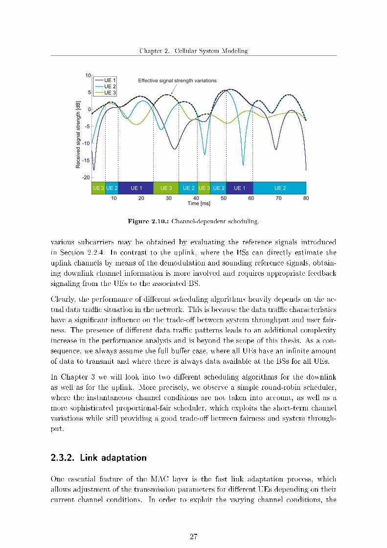
Chapter 2. Cellular System Modeling
Effective signal strength variations
UE 1 UE 3 UE 2 UE 3 UE 2 UE 1 UE 2UE 2UE 3
Figure 2.10.: Channel-dependent scheduling.
various subcarriers may be obtained by evaluating the reference signals introducedin Section 2.2.4. In contrast to the uplink, where the BSs can directly estimate theuplink channels by means of the demodulation and sounding reference signals, obtain-ing downlink channel information is more involved and requires appropriate feedbacksignaling from the UEs to the associated BS.
Clearly, the performance of di�erent scheduling algorithms heavily depends on the ac-tual data tra�c situation in the network. This is because the data tra�c characteristicshave a signi�cant in�uence on the trade-o� between system throughput and user fair-ness. The presence of di�erent data tra�c patterns leads to an additional complexityincrease in the performance analysis and is beyond the scope of this thesis. As a con-sequence, we always assume the full bu�er case, where all UEs have an in�nite amountof data to transmit and where there is always data available at the BSs for all UEs.
In Chapter 3 we will look into two di�erent scheduling algorithms for the downlinkas well as for the uplink. More precisely, we observe a simple round-robin scheduler,where the instantaneous channel conditions are not taken into account, as well as amore sophisticated proportional-fair scheduler, which exploits the short-term channelvariations while still providing a good trade-o� between fairness and system through-put.
2.3.2. Link adaptation
One essential feature of the MAC layer is the fast link adaptation process, whichallows adjustment of the transmission parameters for di�erent UEs depending on theircurrent channel conditions. In order to exploit the varying channel conditions, the
27

Advanced Transmission Schemes for the 4th Generation of Mobile Communication Systems
fast link adaptation dynamically selects an appropriate MCS for each UE. Hence,in situations with advantageous channel conditions, a higher MCS may be selected,while in unfavorable situations a more robust MCS may be chosen. For that purpose,the link adaptation aims at determining the spectrally most e�cient MCS for whicha given target BLER is not exceeded. In this regard, it may choose between severaldi�erent modulation schemes as well as a variety of di�erent channel coding rates (cf.Appendix A). However, due to the random nature of the wireless channels and thetherefore varying radio-link quality, perfect adaptation to the instantaneous channelconditions is generally not possible.
Even if accurate channel information is available at the BS side, the selected linkadaptation parameters are still often not optimal any more when the data transmis-sion actually takes place. This is due to the fact that there is always an inherentdelay between the time when the link adaptation is performed and the actual datatransmission. Clearly, during this time the involved channel conditions as well as theinterference situation naturally change. In particular, this holds for the uplink, wherethe data transmission cannot start until the UEs have received the scheduling grant andthe selected MCS for transmission. A standard approach to countervail this e�ect is toemploy in addition to the fast link adaptation scheme an outer loop mechanism, whichdynamically readjusts the target BLER based on the actually measured BLER suchthat the desired operating point can be achieved at least on average [76, 80]. Withinthis thesis we particularly consider an outer loop link adaptation scheme similar to theone presented in [76]. With this scheme, always a UE-speci�c o�set ∆o�set is added tothe predicted SINR values in dB before performing the actual link adaptation, whichis permanently adjusted based on the outcome of previous transmission attempts. Inparticular, if an (initial) transmission attempt is successful, ∆o�set is increased by δupwhereas otherwise it is decreased by δdown. If these two step sizes δup and δdown arechosen as in [76] such that
δdown|dB =
(1
BLERtarget
− 1
)δup∣∣dB, (2.26)
it is eventually possible to adjust the link adaptation in such a way that the obtainedaverage BLER always corresponds to the con�gured target BLERtarget.
2.3.3. HARQ protocol
In general, transmissions over wireless channels are subject to errors due to the time-varying nature of the involved channels, the changing interference situations as well asthe receiver noise. To some degree, such negative e�ects may be partially mitigatedthrough channel-dependent scheduling or link adaptation as discussed in the previoussections. In order to further improve the radio-link reliability and the spectral e�ciency,the MAC layer provides an additional feature for transmission error handling, namely
28

Chapter 2. Cellular System Modeling
the HARQ protocol. HARQ was �rst proposed in [106] and numerous publicationson HARQ have appeared since then (see for example [27, 60], and references therein).The fundamental idea of HARQ is to detect whether the received transport blocks havebeen transmitted error-free or not by means of an error-detecting code, typically a cyclicredundancy check. If the transport block was successfully transmitted without errors, apositive acknowledgment is signaled from the receiver to the transmitter via the controlchannel. However, if the transport block is erroneously received, the receiver thenimmediately requests a retransmission of this transport block by reporting a negativeacknowledgment to the transmitter.
In contrast to conventional automatic repeat request (ARQ) protocols, the HARQprotocol does not discard erroneously received transport blocks, because they generallycontain useful information. By soft combining with the retransmitted transport blocks,the HARQ protocol makes use of this information to obtain a combined transport block,which is more reliable than its components. Clearly, HARQ retransmissions have tocontain the same set of information bits as the original transmission. However, the set ofcoded bits transmitted in each retransmission may be chosen di�erently. Therefore onecan distinguish between two main soft combining techniques, namely chase combiningand incremental redundancy. While the latter typically uses a di�erent set of coded bitsfor each retransmission, chase combining requires that each retransmission is identicalto the original transmission.
In the case of chase combining, the receiver uses maximum-ratio combining after eachretransmission to combine the received bits with the ones of each previous transmission.This technique was �rst proposed in [21] and it can be seen as additional repetitioncoding. Thus, chase combining does not yield any coding gain, but increases the accu-mulated SINR of the combined transport blocks after each retransmission. By contrast,in the case of incremental redundancy each retransmission generally uses a di�erentset of coded bits to those of the previous transmission [81]. As the retransmission maycontain additional parity bits, which are not included in the previous transmissionattempts, the resulting code rate is generally lowered by a retransmission. Thus, in-cremental redundancy is a generalization of chase combining, which yields both codinggain as well as an improved SINR of the combined transport blocks.
Furthermore, the HARQ protocol can be categorized as either synchronous or asyn-chronous, where for each case one has to distinguish between adaptive or non-adaptiveretransmissions. In the case of a synchronous HARQ protocol, the retransmissionsfor each process occur at prede�ned times relative to the initial transmission. In thisway, there is no need to signal information such as the HARQ process number, asthis can be inferred from the transmission timing. In the case of an asynchronousHARQ, the retransmissions can occur at any time relative to the initial transmission.Therefore additional signaling is required to indicate the HARQ process number tothe receiver in order to correctly associate each transmission with the correspondinginitial transmission. As a result, synchronous HARQ protocols reduce the signaling
29

Advanced Transmission Schemes for the 4th Generation of Mobile Communication Systems
overhead while asynchronous HARQ protocols allow a higher �exibility in schedulingretransmissions. Moreover, if retransmissions are adaptively processed, the transmis-sion parameters such as the MCS and the resource allocation in the frequency domainmay be selected di�erently for each retransmission, depending on the current channelconditions. By contrast, a non-adaptive HARQ protocol restricts the transmission pa-rameters of retransmissions either to be identical to those of the previous transmissionor changing them by a speci�ed rule. Hence, an adaptive protocol yields higher gainsby exploiting the frequency selectivity of the channel, which however comes at the costof increased signaling overhead.
Note that we assume throughout this thesis a synchronous non-adaptive HARQ pro-tocol with incremental redundancy.
2.4. Link-to-system level interface
In order to ensure an accurate evaluation of the system performance of a fourth gen-eration cellular network a realistic system model is required which covers all essentialaspects of a real system that have signi�cant impact on the system performance. Someof these aspects have been already discussed in the previous sections such as the model-ing of the wireless channel, the fast link adaptation, the frequency-selective schedulingor the adaptive HARQ protocol. However, by taking all these aspects for each UE-BSradio link into account, the complexity of such a system model tremendously increases.As a consequence, a certain abstraction of the physical layer is mandatory, since themodeling of each radio link on sample level is not reasonably feasible. In particular,the channel coding and decoding, respectively, is a time-consuming task, which may bee�ciently simpli�ed with the illustrated abstraction model in Fig. 2.11. First of all theactual post-detection SINRs γ = [γ1, . . . , γk, . . . , γK ]T of all subcarriers correspondingto a certain transport block are calculated. Then, an appropriate compression func-tion maps the vector of SINRs γ to a scalar e�ective SINR γe� from which the actualBLER can be determined. Thus, the main goal of the abstraction model is to meet thefollowing approximate equivalence
BLER (γ) ≈ BLERAWGN (γe�) , (2.27)
with BLER (γ) as the actual BLER for the instantaneous SINRs and BLERAWGN (γe�)
as the BLER of an equivalent additive white Gaussian noise (AWGN) channel.
In recent years, a couple of compression functions which take the instantaneous channeland interference conditions into account have been developed, see for example [16, 48,101]. One of the most attractive compression functions is the mutual informatione�ective SINR mapping (MIESM) due to its high accuracy and due to the fact thatit is also applicable if the bits corresponding to a certain transport block are mapped
30

Chapter 2. Cellular System Modeling
Calculation ofpost-detection
SINRs for acertain trans-
port block
SINRcompressionto an effective
SINR
SINR1
SINRK
SINReff Mappingto BLER
BLER
selected MCS
Figure 2.11.: Physical layer abstraction model.
−20 −10 0 10 20 250
1
2
3
4
5
6
I b [bit/
s/H
z]
SINR [dB]
−10 −5 0 5 10 15 2010
−2
10−1
100
BLE
R
SINR [dB]
Look−up tableInterpolation
MCS: QPSK, 1/6MCS: 16QAM, 0.46MCS: 64QAM, 0.62
I6,64QAM
I4,16QAM
I2,QPSK
SINR64QAM
SINReff
Mutual informationBLER
Figure 2.12.: Pre-calculated mutual information curves used for determining the e�ective SINR
as well as the exemplary illustration of the e�ective SINR to AWGN BLER map-
ping.
onto symbols of di�erent modulation alphabets. Within this thesis, we make use ofthis compression function to determine the e�ective SINR given by [16]
γe� = βMIESM I−1bref
1
Kblock
Kblock∑k=1
Ibk
(γk
βMIESM
) , (2.28)
where βMIESM denotes the tuning parameter, Kblock the number of subcarriers pertransport block, γk the SINR of the k-th subcarrier, Ibk the non-linear mutual informa-tion function of the applied modulation alphabet of size 2bk and I−1bref its inverse with brefas the average number of transmitted bits per resource element. The tuning parameterβMIESM allows adjustment of the MIESM to the characteristics of the considered MCS,where we assume throughout this thesis that this parameter is set to βMIESM = 1.2.The mapping function Ibk , which relates the actual SINR to a bit-interleaved codedmodulation capacity can be expressed as [18]
Ibk (x) = bk − EY
1
2bk
bk∑n=1
1∑m=0
∑z ∈Km,ns
log
∑x∈Ks
e−|Y−√x (x−z)|2∑
x∈Km,ns
e−|Y−√x (x−z)|2
, (2.29)
31

Advanced Transmission Schemes for the 4th Generation of Mobile Communication Systems
with Ks as the set of 2bk symbols, Km,ns as the set of symbols for which the bit n equalsto the bit m, and Y as a zero mean unit variance complex Gaussian variable.
In summary, the considered link-to-system interface provides a model for channel cod-ing and decoding which e�ectively models the performance of the actual MCS, tak-ing the current channel and interference conditions into account. The scalar e�ec-tive SINR generated by the MIESM is mapped to a corresponding single-input single-output (SISO) AWGN BLER performance curve. These BLER curves as well as themutual information values according to (2.29) are generally stored in look-up tablesin order to speed up simulations. The look-up table process of the considered link-to-system interface is illustrated as an example in Fig. 2.12. Furthermore, it should benoted that this link-to-system interface may not only be applied for MIMO transmis-sion, but also for BS cooperation techniques discussed in Chapter 5.
32

Chapter 3. Advances in Scheduling and Feedback Methods
3. Advances in Scheduling and
Feedback Methods
Before analyzing the achievable performance of the advanced transmission schemes inthe following chapters, we �rst put the focus on a detailed study of a LTE Release 8based system, which will be used later on as a reference. We look into di�erent schedul-ing methods for the downlink as well as for the uplink. In particular, we distinguishbetween cases where the scheduling is performed independently of the current channelconditions and cases where the channel information is exploited in order to improvethe resource allocation. Furthermore, we outline the di�erences in the downlink anduplink resource allocation for the considered schemes due to the di�erent practicalconstraints associated with OFDMA and SC-FDMA. In order to perform channel-dependent scheduling as well as link adaptation adequate channel information mustbe available at the BS side. In contrast to a TDD system, where it is possible to ex-ploit the estimated uplink channel for the downlink transmission due to the reciprocityprinciple, in a FDD system the BSs rely on the feedback reported by the UEs to ob-tain downlink channel information. Therefore, we propose a novel CSI-based feedbackmethod for providing CSI to the BSs based upon a standard vector quantization tech-nique. Moreover, we compare the performance of this e�cient feedback method to aconventional CQI-based method which, for example, is used in LTE Release 8 [36,38].
Finally, we demonstrate in this chapter the achievable performance of the LTE Re-lease 8 based reference system, considering di�erent receiver types, propagation sce-narios, scheduling algorithms, and the e�ects of HARQ retransmissions as well as powercontrol.
3.1. Round-robin scheduling
A simple channel-independent scheduling strategy is the so-called round-robin schedul-ing, where UEs are periodically allocated to the radio resources irrespective of theircurrent channel conditions. Round-robin scheduling can be seen as fair scheduling inthe sense that the same amount of radio resources is given to each UE. However, thisscheduling strategy is not fair in the sense that it does not provide the same servicequality, often referred to as user fairness, to the UEs. Since round-robin schedulingdoes not take the instantaneous channel conditions into account, the overall systemperformance is generally worse than a channel-dependent scheduling strategy.
33

Advanced Transmission Schemes for the 4th Generation of Mobile Communication Systems
UE 3
UE 1
UE 2
UE 4
UE 5
UE 6
UE 7
UE 3
UE 1
UE 1
UE 1
UE 1
UE 2
UE 2
UE 2
UE 2
UE 4
UE 5
UE 6
UE 7
UE 3
UE 4
UE 5
UE 6
UE 7
UE 3
UE 4
UE 5
UE 6
UE 7
Re-organizationof the assigned
PRBs for theuplink UE 1
UE 1
UE 1
UE 1
UE 1
UE 2
UE 2
UE 2
UE 2
UE 3
UE 3
UE 2
UE 3
UE 3UE 7
UE 7
UE 7
UE 5
UE 5
UE 5
UE 4
UE 4
UE 4
UE 4
UE 7
UE 6UE 6
UE 6
UE 6
UE 5
TTI
PR
B
TTI
PR
B
Time Time
Fre
qu
en
cy
Fre
qu
en
cy
Figure 3.1.: Round-robin scheduling for downlink and uplink transmission.
The round-robin scheduling might be realized as depicted in Fig. 3.1. First of all, eachBS assigns in each TTI all available PRBs consecutively to all associated UEs. Incontrast to the downlink, where the scheduling procedure is completed after this initialassignment, the allocated PRBs have to be re-organized before the scheduling grantscan be forwarded to the scheduled UEs for uplink transmission. This is because theBSs have to ensure that the UEs obtain only consecutive PRBs for their transmissiondue to the allocation constraints associated with SC-FDMA. To this end, each BSrandomly permutes the list of UEs that have been scheduled in order to guarantee thatthe UEs are not always allocated to the same PRBs. Then, the BS assigns adjacentPRBs to the scheduled UEs according to the generated UE list and the correspondingnumber of PRBs allocated to each UE in the initial assignment. In the particular caseillustrated in Fig. 3.1, the UEs one to seven have been assigned in the initial resourceallocation process, thus the list of scheduled UEs is given by
Kue = {1, 2, 3, 4, 5, 6, 7} . (3.1)
In the illustrated case this list is randomly permuted for the �rst TTI to
Kue = {5, 3, 7, 4, 1, 6, 2} . (3.2)
Then, according to the initial resource allocation, the UEs one to three obtain twoPRBs in the �rst TTI, while UEs four to seven only receive one PRB.
34

Chapter 3. Advances in Scheduling and Feedback Methods
3.2. Proportional-fair scheduling
In contrast to a simple round-robin scheduler, channel-aware schedulers allow exploita-tion of the MU diversity as well as the frequency selectivity of the channel by prefer-ably serving UEs with favorable channel conditions. Undoubtedly, such channel-awarescheduling strategies increase the system capacity. However, for that purpose CSI orCQI information over the whole frequency bandwidth is required at the BS side.
In the following, we outline the basic principle of frequency-domain channel-awareproportional fair scheduling. The fundamental idea of proportional fair scheduling isto realize a reasonable trade-o� between the maximal total throughput and cell-edgethroughput. Clearly, on the one hand, fair resource allocation among the UEs will lowerthe overall throughput compared to the maximum possible one, but in return it providesa higher throughput for UEs with relatively poor channel conditions, thus improvinguser fairness. In general, the proportional fair metric is given by the ratio between theinstantaneous supportable and the long-term throughput of a certain UE [104]
Gi,b (t) =Ri,b (t)
TαPFi (t)
, (3.3)
with Gi,b (t) as the scheduling priority for the i-th UE on the b-th PRB during theTTI t, Ri,b (t) as the instantaneous supportable throughput and αPF as the fairnessfactor, which determines the trade-o� between e�ciency in terms of total throughputand fair scheduling. Furthermore, Ti (t) denotes the long-term average throughputgiven by
Ti (t+ 1) =
βPF Ti (t) i /∈ Kue (t)
βPF Ti (t) + (1− βPF) Ri (t) i ∈ Kue (t), (3.4)
where βPF denotes the forgetting factor and Kue (t) as well as Ri (t) denote the setof all scheduled UEs at TTI t and the aggregated throughput of the scheduled UEi, respectively. Having determined the proportional fair metrics in (3.3) for all UEsassociated to a certain BS, the scheduler generally aims at maximizing these prioritiesfor each PRB b and hence selects the UEs according to
xb = arg maxi∈Kue
Gi,b (t) , (3.5)
where xb denotes the UE selected for transmission on the PRB b. However, the com-plexity of the resource allocation process based on maximizing the scheduling prioritiesgenerally depends on the used access scheme. In contrast to the downlink, whereOFDMA is used as access scheme and where the resource allocation can be easily car-ried out according to (3.5), the uplink resource allocation with SC-FDMA is generallymore complex, since the allocated PRBs of a certain UE have to be adjacent in orderto achieve a low peak-to-average power ratio [75]. This leads to a signi�cantly reducedallocation �exibility and a higher complexity. In order to overcome this problem, we
35

Advanced Transmission Schemes for the 4th Generation of Mobile Communication Systems
make use of the uplink resource allocation algorithm presented in [19], which can beapplied after determining the proportional fair metrics in (3.3). The optimal solutionto the resource allocation problem for SC-FDMA would cause a tremendous increase incomputational complexity, as it requires a comparison among all possible PRB assign-ments under consideration of the allocation constraints due to SC-FDMA. Thereforethe basic idea of the resource allocation algorithm in [19] is to start the resource alloca-tion with the PRB associated with the highest scheduling metric and assign adjacentPRBs to the corresponding UE until either a di�erent UE has a higher schedulingpriority or the maximum transmitting power is reached. In this regard, transmittingpower control is performed using a simple open-loop scheme, where the transmittingpower of a certain UE is generally set to (in dBm)
PTX = min{Pmax, P0 + 10 log10MPRB + αPL Pue,bs
}, (3.6)
with Pmax as the maximum transmitting power, P0 as a reference power level, MPRB
as the number of PRBs assigned to the UE, Pue,bs as the long-term attenuation of thechannel between the UE and its serving BS, including path-loss and shadowing, and�nally αPL as a constant path-loss compensation factor. By means of this compensationfactor, the fractional power control scheme is able to adjust the SINR operating pointof the UEs, thus allowing UEs with a higher path-loss to operate at lower SINRs sothat they will more likely generate less interference to neighboring cells. The valuesused for the power control parameters in (3.6) are also given in Appendix A. Note that(3.6) can actually be obtained from the power control formula explicitly speci�ed in [5]by neglecting all (optional) short-term components.
The resource allocation algorithm in [19] aims at assigning UEs approximately accord-ing to the envelope of the scheduling metrics, which is also exempli�ed in Fig. 3.2.In this way, the allocation constraints due to SC-FDMA can be met, while the MUdiversity and the frequency selectivity of the uplink channel can still be exploited.
3.3. Feedback concepts
Next generation mobile communication systems make use of a variety of channel adap-tive techniques such as channel-dependent scheduling, link adaptation or transmissionscheme selection. This implies that the BSs require knowledge of accurate informationabout the current channel conditions. In contrast to the uplink, where the BSs candirectly estimate the uplink channels, appropriate feedback signaling from the UEs tothe associated BS is usually necessary in order to obtain downlink channel informa-tion at the BS side, in particular for FDD systems. However, the downlink channelinformation requirement at the BS side can be easily met with acceptable accuracy forTDD systems, where the same frequency band is used for both downlink and uplinkand where channel information of the downlink can hence be obtained by exploiting
36

Chapter 3. Advances in Scheduling and Feedback Methods
aaaaaaaaaa
aaaaaaaaaa
aaaaaaaaaa
aaaaaaaaaaaaaaaaaaaaaaaaaaaaaaaaaaaaaaaaaaaaaaaaaaaaaaaaaaaaaaaaaaaaaaaaaaaaaaaaaaaaaaaaaaaaaaaaaaaaaaaaaaaaaaaaaaaaaaaaaaa
5 10 15 20 25 30 35 4540 50PRB indices
0
1
2
3
4
5S
ch
ed
ulin
g m
etr
ic v
alu
es
1st maximum
aaaaaaaaaaaaaaaaaaaaaaaaaaaaaaaaaaaaaaaaaaaaaaaaaaaaaaaaaaaaaaaaaaaaaaaaaaaaaaaaaaaaaaaaaaaaaaaaaaaaaaaaaaaaaaaaaaaaaaaaaaa
5 10 15 20 25 30 35 4540 50PRB indices
0
1
2
3
4
5
Sch
ed
ulin
g m
etr
ic v
alu
es
2nd maximum
UE 1 UE 1UE 3
5 10 15 20 25 30 35 4540 50PRB indices
0
1
2
3
4
5
Sch
ed
ulin
g m
etr
ic v
alu
es
3rd maximum
UE 1UE 3 aaaaaaaaaaaaaaaaaaaaaaaaaaaaaaaaaaaaaaaaaaaaaaaaaaaaaaaaaaaaaaaaaaaaaaaaaaaaaaaaaaaaaaaaaaaaaaaaaaaaaaaaaaaaaaa
5 10 15 20 25 30 35 4540 50PRB indices
0
1
2
3
4
5
Sch
ed
ulin
g m
etr
ic v
alu
es
4th maximum
UE 1UE 3 UE 2
(a) (b)
(c) (d)
Figure 3.2.: Illustration of the uplink proportional fair resource allocation algorithm.
channel reciprocity. Obtaining downlink channel information in FDD systems is gener-ally more involved, since the uplink and downlink channels are usually approximatelyuncorrelated due to their separation in frequency. For this reason, several di�erent feed-back concepts have been developed in recent years to ease the FDD uplink feedbackrequirements, see for example [63, 64] and references therein.
In general, one can distinguish between two fundamentally di�erent feedback methodswhere only an indication of the current channel conditions is fed back�often referred toas CQI feedback�and where appropriate CSI is directly reported back to the BSs. TheCQI-based feedback method is a resource-e�cient solution, which has found its wayinto the LTE Release 8 speci�cation [3, 5, 59]. In this regard, the UE selects the mostsuitable precoder under the current channel conditions from a �nite precoder codebookrepresented by a corresponding precoding matrix indicator (PMI). Furthermore, theUE determines a CQI, which is an indication of the supportable data rate, to facilitatea MCS selection at the BS side. The CQI value is based on the estimated SINR underconsideration of the recommended precoder and the receiver type.
In contrast to the CQI feedback method, where the channel information is sent to theBS implicitly by the PMI, the estimated downlink channel itself is explicitly reportedby a CSI feedback method. This promising feedback method is based upon appropriatequantization techniques, where the estimated CSI is e�ciently quantized by the UEsand then fed back to the serving BS via a low-rate feedback channel [29, 53, 98, 108].Thus, suitable precoders can be designed directly at the BS side leading to a higher�exibility and a better exploitation of the spatial dimension of the channel comparedto the CQI-based method. However, this feedback method represents a major shiftin the feedback paradigm compared to CQI-based approaches. But with a view to
37

Advanced Transmission Schemes for the 4th Generation of Mobile Communication Systems
future transmission techniques, more sophisticated CSI-based feedback methods arecurrently under discussion for next generation mobile communication standards, suchas LTE Release 10, with the aim of further improving the spectral e�ciency.
In the following, we propose two di�erent low-rate feedback methods based on CQI andCSI, respectively, and present an equitable comparison of the achievable performanceof both feedback methods [36,38].
3.3.1. CQI feedback
Similar to LTE Release 8, we assume that the UEs periodically send dedicated CQIreports back to their serving BS, containing CQI values, a PMI as well as a rankindicator (RI). A CQI value corresponds to the spectrally most e�cient MCS thatcan be supported by the current downlink channel without exceeding a given targetBLER. The number of reported CQI values depends on the number of data streamsto be transmitted and therefore also on the RI, which explicitly speci�es the numberof spatial layers. As a consequence, the RI may be used as selection criterion forswitching between di�erent SU-MIMO transmission schemes. In this regard, we assumethroughout this thesis that either transmit beamforming or spatial multiplexing canbe selected as SU-MIMO transmission scheme [3, 42]. While transmit beamforming isgenerally used in situations with unfavorable channel conditions to increase the receiveSINR by shaping the overall antenna beam in the direction of the target receiver,spatial multiplexing on the other hand allows for a more e�cient utilization of highlydecorrelated channels with high SINRs by simultaneously transmitting multiple datastreams.
Each UE may only report one wideband RI for the whole bandwidth�given by thetotal number of OFDM subcarriers�, due to the fact that the improvement arisingfrom PRB-dependent data stream and transmission scheme selection, respectively, doesnot justify the additionally required control signaling. Thus, even if a certain UE isscheduled on multiple PRBs, the same number of data streams and therefore sametransmission scheme always has to be used [5, 86].
According to the standard CQI reporting in LTE Release 8, the total number of OFDMsubcarriers is subdivided into Lsub di�erent subbands which are integer multiples ofPRBs. For each of these subbands a separate CQI report is generated in order toexploit the frequency selectivity of the channel. In order to select an appropriate CQIand PMI for each subband, we determine �rst of all the wideband RI given as the ratioof the maximal achievable rates over the whole bandwidth with transmit beamformingand spatial multiplexing, respectively. Thus, the RI can be calculated by [36]
RI =
1, if ζCQI ≥ η thr, CQI
> 1, if ζCQI < η thr, CQI, (3.7)
38

Chapter 3. Advances in Scheduling and Feedback Methods
where ζCQI is de�ned as
ζCQI =
Lsub∑l=1
maxFµ∈ KB
RB
(l, Fµ
)Lsub∑l=1
maxFν∈ KS
RS (l, Fν)
µ = 1, . . . , |KB| , ν = 1, . . . , |KS| , (3.8)
with η thr, CQI as a prede�ned threshold value for comparing the achievable rates of bothtransmission schemes over the whole bandwidth, RB
(l, Fµ
)as the achievable rate in
the case of transmit beamforming for the l-th subband and the precoder Fµ out of theset KB, RS (l, Fν) as the achievable rate in the case of spatial multiplexing for the l-thsubband and the precoder Fν out of the set KS, and KB as well as KS as the precodersused for transmit beamforming and spatial multiplexing, respectively. Note that wemake use of the standardized LTE Release 8 precoder codebook in the following [3].This precoder codebook is based on rows and columns of a DFT matrix in the case oftwo transmit antennas, whereas in the case of four transmit antennas it is generatedby means of the following Householder transformation [44]
Fi = I4 −2uiu
Hi
uHi ui, (3.9)
where I4 is the 4×4-dimensional identity matrix. The transformation in (3.9) generatesunitary matrices based on the input vectors ui, which are de�ned in [3] and which arealso listed together with the LTE Release 8 precoder codebooks in Appendix B.
The achievable rates in (3.8) may be estimated by means of the Shannon capacityformula
R(l,Fi,l
)= log2
(1 + γi,l,Fi,l
), (3.10)
with γi,l,Fi,l as the e�ective downlink SINR of UE i for the subband l and the corre-sponding precoding matrix Fi,l. It should be noted that in the case of spatial multi-plexing, the achievable rate is the sum of all rates corresponding to each simultaneouslytransmitted data stream. As a consequence, for each data stream and subband the re-spective MCS index is signaled back to the serving BS. Let us assume that the receiveddownlink signal yi,k ∈ C[Nbs×1] for UE i on a subcarrier k belonging to the consideredsubband l may be expressed as
yi,k = Hi,k Fi,l si,k + ii,k + ni,k, (3.11)
where Hi,k ∈ C[Nue×Mbs] denotes the downlink channel between UE i and its servingBS, Nue the number of receive antenna elements per UE, Mbs the number of transmitantenna elements per BS sector, Fi,l ∈ C[Mbs×ri] the precoding matrix for subband l,si,k ∈ C[ri×1] the transmitted signal, ii,k ∈ C[Nue×1] the inter-cell interference caused bythe simultaneous transmissions of other BSs and ni,k ∈ C[Nue×1] the zero mean AWGN.Furthermore, ri ≤ rank
(Hi,k
)≤ min (Nue,Mbs) indicates the number of transmit data
39

Advanced Transmission Schemes for the 4th Generation of Mobile Communication Systems
streams to UE i. According to (3.11) the received downlink SINR γi,k,Fi,l for subcarrierk is given by
γi,k,Fi,l =Wi,kHi,k Fi,l E
[si,k s
Hi,k
]FHi,lH
Hi,kW
Hi,k
Wi,k
(E[ii,k i
Hi,k
]+ E
[ni,k n
Hi,k
])WH
i,k
, (3.12)
where Wi,k ∈ C[Mbs×Nue] denotes the corresponding weight matrix for coherent detec-tion. By means of the MIESM interface (cf. Section 2.4) we obtain the e�ective SINRγi,l,Fi,l for the whole subband l by simply plugging the calculated SINRs in (3.12) forall subcarriers belonging to the considered subband l into (2.28). The e�ective SINRγi,l,Fi,l in turn is used to determine the spectrally most e�cient MCS for the consideredsubband l with which the imposed target BLER would not be exceeded.
Having determined the RI in (3.7), the best precoder and MCSs, maximizing theachievable rate with the selected transmission scheme, are then reported back to serv-ing BS for each subband. Based on the signaled CQI reports, the BSs are able toaccurately estimate the achievable rates for each subband, thus enabling frequency-selective channel-dependent scheduling and link adaptation.
3.3.2. CSI feedback
In the following, we propose a novel CSI-based low-rate feedback scheme. In con-trast to LTE Release 8, where UEs periodically send dedicated CQI reports back totheir serving BS, we assume here that instead appropriate CSI reports are generatedat regular intervals, containing quantized information about the estimated downlinkchannel as well as the current interference situation. As already mentioned before, thismethod represents a fundamental change compared to CQI based feedback approaches.However, such CSI feedback techniques are currently being discussed for future mobilecommunication standards, such as LTE Release 10, and may therefore �nd their wayinto the further evolution of mobile communication systems.
The main di�erence to most previous works related to CSI-based feedback is that wealso address the problem of how information about the current interference situationmight be e�ciently quantized by the UEs so that this information can be fed backto the corresponding serving BS via a rather low-rate feedback channel. Most of therecently proposed CSI-based feedback methods mainly focus on the design of appropri-ate precoders at the transmitter side and hence only provide either channel directioninformation (CDI) (see for example [30,53,71,82]) or CDI together with channel mag-nitude information (CMI) [52, 88]. However, apart from the CDI and CMI, additionalknowledge about the current interference situation observed by the UEs is essential atthe BS side in a realistic interference limited network. This is because the interferenceinformation is required not only for the proper design of the precoding matrices, butalso for channel-dependent scheduling and the link adaptation process, in particular
40

Chapter 3. Advances in Scheduling and Feedback Methods
for the selection of appropriate MCSs. Note that as an alternative to the direct re-porting of the current interference situation as proposed below, a SINR value, whichimplicitly includes an estimate of the interference situation, may be fed back to theBSs as proposed, for example, in [29, 99]. However, the explicit knowledge of the in-terference situation at the BS side is usually more bene�cial, since the �exibility inselecting an appropriate transmission mode and MCSs as well as designing precodersis considerably increased.
In order to exploit the frequency selectivity of the channel, the total number of OFDMsubcarriers is�similar to standard CQI reporting in LTE Release 8�subdivided intoLsub di�erent subbands: for each of these subbands, a separate CSI report is thengenerated. Based on the received CSI reports, the BSs perform frequency-selectivechannel-dependent scheduling and determine the transmission mode, appropriate pre-coding weights, and the MCSs to be used by the scheduled UEs. At this point, weemphasize again that even if a certain UE is scheduled on multiple PRBs, it mayonly use one transmission scheme and one MCS per spatial stream due to signalingconstraints in the downlink, thus leading to additional restrictions in the schedulingprocedure.
3.3.2.1. CSI quantization
For obtaining CSI, each UE �rst of all estimates over the whole bandwidth�given by allOFDM subcarriers�the channel from its associated BS based on cell-speci�c referencesymbols. In order to keep the uplink feedback load limited, only one quantized channelmatrix is fed back for each subband. To this end, �rst of all the arithmetic meanHl ∈ C[Nue×Mbs] of all channel estimates for subband l is calculated by
Hl =1
Kl
Kl∑k=1
Hk,l , l = 1, . . . , Lsub, (3.13)
with Hk,l ∈ C[Nue×Mbs] as the k-th estimated downlink channel within subband l andKl as the number of downlink channels which can be estimated by means of the ref-erence signals contained in subband l. Then, we separately quantize the direction andmagnitude information of
hl = vecHl =[hT1 hT2 · · · hTMbs
]T(3.14)
in order to allow for e�cient processing and a �exible allocation of feedback bits toeither type of information. The CDI is quantized by �nding the codebook vector outof the considered quantization codebook with the minimum chordal distance to thenormalized stacked vector of the channel matrix hl/||hl||, where the chordal distancebetween two vectors is generally de�ned as [25]
dc (x,y) = sin θ (x,y) =
√(1−
(xH · y
)2), (3.15)
41

Advanced Transmission Schemes for the 4th Generation of Mobile Communication Systems
with θ (x,y) as the principal angle between the two unit norm vectors x and y. Hence,the quantized channel direction can be obtained as
hCDI,l = arg mincm∈ C
dc
(hl
‖hl‖, cm
), m = 1, . . . ,MCDI, (3.16)
where C ={c1, c2, . . . , cMCDI
}denotes the CDI codebook consisting of MCDI = 2BCDI
unit norm vectors with BCDI as the number of feedback bits used for reporting theCDI. For quantizing the CMI, in contrast, a simple scalar quantizer is applied usingequidistant quantization intervals within the region
min1≤m≤MT
‖xm‖ ≤ ‖hl‖ ≤ max1≤m≤MT
‖xm‖ , (3.17)
where T ={x1,x2, . . . ,xMT
}denotes the training set, which captures the statistical
properties of the stacked channel vectors hl ∈ C[(NueMbs)×(NueMbs)] in (3.14). Thesechannel matrix samples are required for generating the CDI codebook C, which will beexplained in more detail in the next section.
As already mentioned before, an indispensable prerequisite for the e�cient applicationof fast link adaptation, channel-dependent scheduling as well as transmission modeselection with CSI-based feedback in cellular networks is the availability of accurateinformation about the current interference situation observed by the UEs at the BS side.For that reason, each UE makes use of its interference measurements, which are usuallyrequired for coherent detection anyway. Similar to the CDI quantization approachdescribed above, the set of measured main diagonals of the interference covariancematrices for each subband l is arithmetically averaged by
Rii,l =1
Kl
Kl∑k=1
diag
(E[ik,l i
Hk,l
]), l = 1, . . . , Lsub, (3.18)
where we assume that each UE is only able to measure the interference level per receiveantenna. In order to capture the temporal variability of the inter-cell interference,the arithmetically averaged interference covariance matrices in (3.18) are additionally"averaged" over time at each interference measurement interval T I according to
Rii,l
((k + 1) T I
)= β I Rii,l (k T I) + (1− β I) Rii,l (k T I) , k = 0, 1, . . . , (3.19)
with β I as a forgetting factor. Clearly, Rii,l ∈ C[Nue×Nue] is a diagonal matrix and thediagonal elements may be expressed by
rµµ,l = αµ,l 10−βµ,l , µ = 1, . . . , Nue, (3.20)
with αµ,l and βµ,l as the mantissa and exponent of each diagonal element rµµ,l. Weemploy a simple approach by quantizing the mantissa and exponent of each diagonal
42

Chapter 3. Advances in Scheduling and Feedback Methods
element separately using equidistant intervals and hence the quantized mantissa andexponent can be obtained as
αµ,l = arg minxm∈ CM
∣∣αµ,l − xm∣∣ , m = 1, . . . ,MM, (3.21)
βµ,l = arg minyn∈ CE
∣∣βµ,l − yn∣∣ , n = 1, . . . ,ME, (3.22)
where CM ={x1, x2, . . . , xMM
}and CE =
{y1, y2, . . . , yME
}denote the mantissa and
exponent codebook consisting of MM = 2BM and ME = 2BE entries, respectively. Fur-thermore, BM and BE indicate the number of feedback bits used for reporting thecorresponding information. Assuming that the interference received at the various an-tenna elements is highly correlated�what should be usually the case for UE devicesof small size due to closely spaced antenna elements�then we obtain the followingapproximate equivalence
rµµ,l ≈ rνν,l , ∀µ 6= ν. (3.23)
As the interference level per receive antenna is almost the same for closely spaced UEantenna elements, the uplink feedback load can be considerably reduced by quantizingonly one of these diagonal elements and assuming that it is the same for all of them.
Moreover, another very attractive approach for interference information signaling isthe quantization of the long-term average interference covariance matrices, because onthe one hand the uplink signaling can be further reduced in this way and on the otherhand the interference situation is generally instantaneously changing from one TTI tothe next anyway since, di�erent UEs with di�erent precoders might be scheduled. Theaverage interference covariance matrix Rii,l having been quantized according to (3.21)and (3.22), this information may be then fed back at a certain reporting interval, whichis much longer than the one used for signaling the CDI and CMI.
3.3.2.2. Codebook design
Various precoder as well as channel codebook construction methods based on standardvector quantization with low-rate feedback have been extensively investigated recently(see for example [53, 56, 62, 65, 84, 88, 109]). However, most of the proposed meth-ods focus on the construction of precoding matrix codebooks designed for SU-MIMOscenarios. The main drawback of these codebooks is that the performance will be sig-ni�cantly degraded in the case of MU-MIMO transmission, for example, which will beintroduced in Chapter 4. This is because these codebooks are designed in such a waythat the UEs select suitable precoders aiming at maximizing a speci�c criterion such asthe mutual information or the average signal-to-noise ratio [62, 65, 84], without takingthe interference caused to other UEs into account. Hence, a more e�cient way is todirectly quantize the channel matrix, similar to the method presented in [56].
The construction of the CDI codebook C in (3.16) is based on the well-known Linde-Buzo-Gray (LBG) vector quantization algorithm in [61], which shows a reasonable
43

Advanced Transmission Schemes for the 4th Generation of Mobile Communication Systems
trade-o� between complexity and achievable performance. The objective of a vectorquantizer Q is to map a set of source or training vectors T =
{x1,x2, . . . ,xMT
}by a
�nite set of codebook vectors C ={c1, c2, . . . , cMC
}, thus
Q : T −→ C. (3.24)
Associated with each codebook vector cn is a partition Rn de�ned by
Rn ={x ∈ T : Q (x) = cn
}. (3.25)
In general, the codebook design is optimal if, for a given codebook size MC and a setof training vectors T , it minimizes the distortion error [61]
J = minC
1
MT
MC∑n=1
∑xm∈Rn
d (xm, cn) , (3.26)
where we make use of the chordal distance in (3.15) for the distance function d (x, c)
similar to [56,109]. In order to satisfy the minimization criterion in (3.26), the iterativeLBG algorithm has to full�ll two main conditions, namely the nearest neighbor andthe centroid condition [61]. The nearest neighbor condition
Rn ={x ∈ T : dc (x, cn) < dc (x, cm) , for cn, cm ∈ C, ∀n 6= m
}(3.27)
states that the training vectors should be assigned to their nearest codebook vector or,in other words, the partition Rn should consist of all training vectors that are closerto the corresponding codebook vector cn than any of the other codebook vectors. Foreach partition Rn�often referred to as Voronoi partition [40]�the optimal codebookvector is given by the centroid condition
cn,opt = arg minc
1
MRn
∑xm∈Rn
dc (xm, c) , (3.28)
which de�nes the centroid or center of the MRn vectors assigned to the partition Rn
and hence aims at minimizing the distortion in the partition Rn. It has been shownin [109] that the optimal codebook vector cn,opt for the partition Rn in (3.28) is givenby the eigenvector of
ΦRn =1
MRn
∑xm∈Rn
xmxHm, (3.29)
corresponding to the largest eigenvalue in the eigenvalue matrix DΦRnof the eigende-
composition ofΦRn = UΦRn
DΦRnUH
ΦRn. (3.30)
As mentioned before, the iterative LBG algorithm converges to a solution satisfyingthe minimization criterion J in (3.26). However, the solution is locally optimal andmight not be globally optimal and is therefore heavily dependent on the choice of theinitial codebook [109]. Consequently, we make use of a splitting method, similar to
44

Chapter 3. Advances in Scheduling and Feedback Methods
(a) Codebook size = 4
CodewordTraining setVoronoi borders
(d) Codebook size = 32
CodewordTraining setVoronoi borders
(b) Codebook size = 8
CodewordTraining setVoronoi borders
(c) Codebook size = 16
CodewordTraining setVoronoi borders
Figure 3.3.: Illustration of the Voronoi partitions for di�erent steps of the iterative LBG algo-
rithm.
the one presented in [88], in order to obtain an appropriate initial codebook from thetraining set consisting of channel samples which capture the statistical properties ofthe stacked channel vectors in (3.14). To this end, we �rst of all determine an initialcodebook vector representing the centroid of the entire training set with the help of thecentroid condition in (3.28). This initial codebook vector is then split into two vectors,which are used as the initial codebook. This codebook is then iteratively re�ned bymeans of the two optimality conditions in (3.27) and (3.28). At the end of each iterationthe minimum chordal distance of the obtained tentative codebook is determined andcompared to the one of the current codebook. The codebook can be improved untilthe condition
dc,min (Cten) > dc,min (Ccur) , (3.31)
with Cten as the tentative codebook, Ccur as the current codebook, and dc,min (C) as theminimum chordal distance of a codebook C which is de�ned by
dc,min (C) = min dc (cn, cm) , for cn, cm ∈ C, ∀n 6= m. (3.32)
At the end of each codebook optimization the codebook vectors are split again andthe same iterative process is repeated until the desired codebook size is reached. Theiterative codebook construction process is shown as an example in Fig. 3.3. Further-more, it should be noted that, in a practical system, several di�erent codebooks wouldideally be available to adapt to the large number of possible channel conditions thatmay occur, including line-of-sight and non-line-of-sight scenarios or various levels ofspatial correlation. These codebooks might then be dynamically selected dependingon the prevalent situation, which is, however, beyond the scope of this thesis.
45

Advanced Transmission Schemes for the 4th Generation of Mobile Communication Systems
In summary, the idea of our novel CSI-based feedback method is to separately quan-tize the CDI and CMI of the downlink channel based upon the well-known LBG vectorquantization algorithm in order to allow for an e�cient processing and a �exible allo-cation of feedback bits to either type of information. Apart from that, our feedbackconcept additionally takes into account e�cient methods for quantizing and signalinginformation about the interference situation observed by the UEs. This interferenceinformation is essential for choosing appropriate precoders and particularly for facili-tating an e�cient link adaptation.
3.3.2.3. CSI-based SU-MIMO precoding
Having quantized the channel and interference information, the UEs send the corre-sponding codebook indices back to their serving BSs through the low-rate feedbackchannel. Then, the BSs are able to reconstruct the channel matrix by looking up thecorresponding entries in the CDI and CMI codebooks, which are known at both UEand BS side. The reconstructed channel matrix Hi,l ∈ C[Nue×Mbs] for subband l is thenused for the calculation of the individual SU-MIMO precoding matrix Fi,l ∈ C[Mbs×ri]
of a certain UE i given byFi,l = Vi,l,ri , (3.33)
where ri ≤ rank(Hi,l
)≤ min (Nue,Mbs) denotes the number of transmit data streams
to UE i and whereVi,l,ri is made up of the eigenvectors corresponding to the ri strongesteigenvalues of the reconstructed channel matrix
Hi,l = Ui,lDi,lVHi,l. (3.34)
Here Ui,l and Vi,l denote unitary matrices and Di,l indicates a diagonal matrix con-taining the singular values of Hi,l sorted in descending order. Furthermore, we assumethat the transmitting power is equally split up among the transmit data streams andthat the total transmitting power per subcarrier k in (3.11) is always constraint to PTor equivalently that
E[∥∥Fi,l si,k∥∥2] ≤ PT . (3.35)
With a CSI-based precoding scheme at the BS side as considered here, the UEs alsohave to estimate the used precoding matrices to be able to demodulate the transmittedsignals. In this regard, we assume that additional UE-speci�c reference symbols�asspeci�ed in LTE Release 9 [4]�are introduced during data transmissions, which areprecoded with the same precoding weights as the actual data symbols.
3.3.2.4. CSI-based transmission scheme selection
In contrast to the CQI-based feedback approach, where the SU-MIMO transmissionscheme selection is performed by the UEs themselves, this process is shifted to the BS
46
Chapter 3. Advances in Scheduling and Feedback Methods
side in the case of CSI feedback. However, similar to the CQI case, the transmissionscheme is chosen for each UE before the actual scheduling process is performed in orderto reduce the computational complexity due to the restriction that, irrespective of theassigned PRBs, the same transmission scheme always has to be used. Without anypreselection of the transmission scheme, the scheduling would require a non-trivial andtime-consuming comparison among all possible PRB assignments taking all possibletransmission schemes into account. As a consequence, we �rst of all determine foreach subband and UE the precoding matrices for transmit beamforming and spatialmultiplexing according to (3.33). Then, we calculate the ratio of the achievable ratesfor both transmission schemes over the whole bandwidth given by
ζCSI =
Lsub∑l=1
Rbeam
(l, Fbeam,l
)Lsub∑l=1
Rsmux
(l, Fsmux,l
) , (3.36)
with Rbeam
(l, Fbeam,l
)as the rate in the case of transmit beamforming for the l-th
subband and the precoder Fbeam,l, Rsmux
(l, Fsmux,l
)as the rate in the case of spatial
muliplexing for the l-th subband and the precoder Fsmux,l. The ratio ζCSI is comparedto a prede�ned threshold η thr, CSI according to
Selection =
transmit beamforming, if ζCSI ≥ η thr, CSI
spaial multiplexing, if ζCSI < η thr, CSI, (3.37)
in order to select the appropriate SU-MIMO transmission scheme. Note that the valuefor the prede�ned threshold η thr, CSI is listed in the simulation parameters table givenin Appendix A.
3.4. Baseline system performance
In this section we present some selected system-level simulation results for the downlinkand uplink of our LTE-based reference system. More precisely, we demonstrate theimpact of frequency-selective proportional fair scheduling, HARQ retransmissions aswell as uplink power control on the system performance. Furthermore, we thoroughlyinvestigate the e�ects of imperfect CSI at the BS side, since in practice the uplinkfeedback information for obtaining downlink CSI is generally limited to a few bits only.As a result, the accuracy of the reported CSI becomes limited as well, a factor whichleads to a performance degradation compared to the optimal case with perfect CSI atthe BS side. Finally, we compare the achievable system performance with CQI-basedfeedback to a system utilizing our novel CSI-based feedback method. For that purpose,we spend the same amount of feedback bits for both feedback methods, leading to a fairperformance comparison that provides a basis for evaluating which feedback method
47

Advanced Transmission Schemes for the 4th Generation of Mobile Communication Systems
performs better for the considered SU-MIMO LTE scenario. If not stated otherwise, wealways assume the default simulation parameters given in Appendix A for the followingsystem-level simulation results.
3.4.1. Downlink results
Fig. 3.4 shows the downlink system performance of CQI-based SU-MIMO with pro-portional fair scheduling, where all BSs and all UEs are equipped with two antennaelements each. Both the average spectral e�ciency as well as the cell-edge throughput�de�ned as the 5th percentile point of the cumulative distribution function of the UEthroughput�are illustrated as a function of the fairness factor. It can be seen fromFig. 3.4 that the fairness factor has a signi�cant in�uence on the trade-o� betweensystem throughput and user fairness. In general, a proportional fair scheduler ensuresthat UEs located at the cell-edge are also scheduled by assigning radio resources to theUEs with advantageous channel conditions, regardless of the absolute transmission linkquality. However, if the fairness factor is small, the proportional fair scheduler thentends towards a maximum rate scheduler, which allocates radio resources only to UEswith the instantaneously best channel conditions. This leads to a high system capacity,but poor cell-edge throughput, as may be seen in Fig. 3.4. In addition to the impactof the fairness factor, Fig. 3.4 shows also the observed performance with and with-out HARQ, considering di�erent BLERs as well as receiver types. In this regard, weconsider the LMMSE and LMMSE-SIC receivers as outlined in Section 2.2.5. Clearly,the LMMSE-SIC receiver outperforms a conventional LMMSE receiver: however, thiscomes at the cost of an increased computational complexity at the UE side. An in-crease of the target BLER gives rise to a more aggressive selection of the MCSs. Asa result, transport blocks are more often erroneously received: hence more retransmis-sions are requested compared to the case with a lower target BLER, which degradesthe performance, as shown in Fig. 3.4. Finally, Fig. 3.4 illustrates that the systemperformance can be signi�cantly increased with a HARQ protocol. Interestingly, theachievable gains compared to a system without HARQ protocol are steadily rising withincreasing fairness factor. This is because more cell-edge UEs are scheduled in the caseof a high fairness factor, and since these UEs bene�t the most from a HARQ protocol,the system performance improves.
Fig. 3.5 shows the impact of imperfect CSI at the BS side in the case of SU-MIMO withCSI-based feedback. As before, all BS sectors and UEs have two antenna elements.Furthermore, we assume that only the average interference levels are known at the BSside. To this end, the long-term average interference covariance matrix is quantizedas described in Section 3.3.2.1, considering only a single element out of the diagonalelements. In this regard, the mantissa quantization granularity is set to BM = 8 bits persubband, whereas the exponents of the various interference levels are always quantizedwith a resolution of BE = 3 bits per subband. The interference information reporting
48

Chapter 3. Advances in Scheduling and Feedback Methods
0,6 0,8 1 1,2 1,4 1,6 1,8 2.0
1.2
1.4
1.6
1.8
2.0
2.2
2.4
Fairness factor aPF
Ave
rag
e s
pe
ctr
al e
ffic
ien
cy [
bit/s
/Hz/s
ecto
r]
0,6 0,8 1 1,2 1,4 1,6 1,8 2.0
300
400
500
600
700
800
Fairness factor aPF
Ce
ll-e
dg
e U
E t
hro
ug
hp
ut
[kb
ps]
LMMSE-SIC, BLER 10%, w/ HARQ
LMMSE, BLER 10%, w/ HARQ
LMMSE, BLER 30%, w/ HARQ
LMMSE, BLER 10%, w/o HARQ
2001.0
Figure 3.4.: Downlink system performance of a 2x2 CQI-based SU-MIMO system for the Urban
Macro 1 case and proportional fair scheduling with and without HARQ, considering
two di�erent receiver types as well as di�erent target BLERs.
2 3 4 5 6 7 81
1.1
1.2
1.3
1.4
1.5
1.6
1.7
1.8
BCMI
[bits/subband]
Avera
ge s
pectr
al effic
iency [bit/s
/Hz/s
ecto
r]
2 3 4 5 6 7 8250
300
350
400
450
500
BCMI
[bits/subband]
Cell-
edge U
E thro
ughput [k
bps]
BCDI
® ¥
BCDI
= 10
BCDI
= 8
BCDI
= 6
BCDI
= 4
BCDI
= 2
Figure 3.5.: Impact of the CDI and CMI quantization on the downlink system performance for
a 2x2 CSI-based SU-MIMO system with proportional fair scheduling, considering
the Urban Macro 1 case. The interference information is reported every 200TTIs
and the quantization granularity is set to BE = 3 and BM = 8 bits per subband.
interval is set to 200TTIs and hence is much longer than the CDI and CMI feedbackinterval of 5TTIs. As may be seen from Fig. 3.5, by increasing the accuracy of theCMI, the performance �rst of all can be gradually improved, but at a certain pointthe corresponding curves saturate. If, in contrast, the number of bits BCDI spent forthe CDI is increased, no such saturation can be observed for the considered parametersettings. This indicates that the system performance is generally more susceptible to
49

Advanced Transmission Schemes for the 4th Generation of Mobile Communication Systems
50 100 150 2001.4
1.45
1.5
1.55
1.6
1.65
Interference reporting interval TIR
[TTI]
Ave
rag
e s
pe
ctr
al e
ffic
ien
cy [
bit/s
/Hz/s
ecto
r]
50 100 150 200360
370
380
390
400
410
420
430
440
450
460
Interference reporting interval TIR
[TTI]C
ell-
ed
ge
UE
th
rou
gh
pu
t [k
bp
s]
Ideal
All elements
Single element
55
BM
= 4 bits / subband
BM
= 4 bits / subband
BM
= 8 bits / subband
BM
= 8 bits / subband
Figure 3.6.: Impact of the interference quantization on the system performance for 2x2 CSI-
based SU-MIMO system with proportional fair scheduling for the Urban Macro 1
case. The CDI and CMI are quantized with a resolution of BCDI = 5 and BCMI = 3
bits per subband, respectively.
the accuracy of the CDI, and it therefore seems in most cases preferable to spend morebits for the quantization of this information than for the quantization of the CMI ifthe total number of feedback bits is �xed.
The average spectral e�ciency as well as the cell-edge throughput are depicted as afunction of the interference information reporting interval in Fig. 3.6. Again, all BSsand UEs are equipped with two antenna elements, and we assume that the accuracyof the channel quantization is set to BCDI = 5 and BCMI = 3 bits per subband,respectively, and that the exponent of the interference elements are quantized witha resolution of BE = 3 bits per subband. It can be seen that the system performance issteadily decreasing with increasing interference reporting interval. This is because thereported interference information no longer matches the actual interference situation,leading to a poor estimation of the actual SINRs at the BS side. Thus, the accuracyof the link adaptation process degrades, since the selected MCSs are frequently over-or underestimated, which in turn results in a system performance drop. Furthermore,we note from Fig. 3.6 that quantizing only a single element leads to approximately thesame performance as if both diagonal elements of the interference covariance matrix arequantized, re�ecting the fact that the two di�erent UE antenna elements are obviouslyhighly correlated. More importantly, however, it can be seen that the performance loss,if only quantized interference information is available at the BS side instead of perfectknowledge, is only minor.
Fig. 3.7 shows the downlink system performance comparison between CQI-based andCSI-based SU-MIMO with proportional fair scheduling for the Urban Macro 1 case,where a SU-MIMO LTE Release 8 system with CQI feedback and round-robin schedul-
50

Chapter 3. Advances in Scheduling and Feedback Methods
2x2 4x20
0.2
0.4
0.6
0.8
1
1.2
1.4
1.6
1.8
2
2.2
2.4
Avera
ge s
pectr
al effic
iency [bit/s
/Hz/s
ecto
r]
Antenna constellation2x2 4x2
0
100
200
300
400
500
600
700
800
Cell-
edge U
E thro
ughput [k
bps]
Antenna constellation
CQI, Proportional-fair
CSI, Proportional-fair
CQI, Round-robin
+32%+29%
+43%
+32%
+33%+34%
+44%+43%
Figure 3.7.: Fair downlink system performance comparison between CQI- and CSI-based SU-
MIMO with proportional fair scheduling for the Urban Macro 1 case. The given per-
centages denote the relative performance gains compared to a conventional LTE Re-
lease 8 CQI-based SU-MIMO system with round-robin scheduling.
Table 3.1.: Uplink feedback load comparison.
CQI feedbackNumber of transmit antennas
2 4
MCS for transmit beamforming [bits/subband] 0.8 ∗ 5 = 4 0.8 ∗ 5 = 4
MCSs for spatial multiplexing [bits/subband] 0.2 ∗ 10 = 2 0.2 ∗ 10 = 2
PMI [bits/subband] 2 4
RI [bits/total number of OFDM subcarriers] 1 (neglected) 2 (neglected)
Total number of feedback bits per subband 8 10
CSI feedbackNumber of transmit antennas
2 4
CDI [bits/subband] 5 7
CMI [bits/subband] 3 3
Long-term interference exponent [bits/subband] 3 (neglected) 3 (neglected)
Long-term interference mantissa [bits/subband] 8 (neglected) 8 (neglected)
Total number of feedback bits per subband 8 10
ing is used as a reference. In order to evaluate which feedback method performs betterin the considered LTE scenario, a fair performance comparison is considered in thefollowing. To this end, we spend approximately the same amount of feedback bits persubband for both SU-MIMO schemes, as summarized in Table 3.1 for the case that allUEs have two receive antennas and all BS sectors are equipped with either two or fourantenna elements. While the MCS as well as the PMI are signaled for each subband inthe case of CQI reporting, the RI is only reported for the whole bandwidth as outlinedin Section 3.3.1. Thus, we are neglecting the required number of feedback bits for sig-naling the RI in our further considerations. As a result, we spend approximately eightbits per subband on average, under the reasonable assumption that in 20% of all cases
51

Advanced Transmission Schemes for the 4th Generation of Mobile Communication Systems
spatial multiplexing is requested as transmission scheme by the UEs, whereas for theremaining 80% transmit beamforming is chosen. The same holds for the CSI-basedfeedback method, if we neglect the required feedback bits for signaling the long-terminterference levels. In this regard, we assume that only a single element of the diagonalelements of each long-term interference covariance matrix is quantized per subbandand reported back every 50TTIs to the BS. Thus, the interference reporting intervalis much longer than for the CDI or CMI feedback: therefore, neglecting these bits isalso a reasonable assumption.
It can be seen from Fig. 3.7 that similar performance gains can be achieved with bothfeedback schemes, although the gains for the CQI-based method are slightly higher thanfor the CSI-based method, in particular for the case where all BSs and UEs are equippedwith two antenna elements each. This can be explained by the fact that, with CSI-based precoding, additional UE-speci�c reference symbols are required�as speci�ed inLTE Release 9 [4]�to demodulate the transmitted signals, causing additional signalingoverhead and hence degrading the system performance. Moreover, we note from Fig. 3.7that channel-dependent scheduling, such as proportional fair scheduling as consideredhere, outperforms a simple round-robin scheduling strategy, where the instantaneouschannel conditions are not taken into account. Due to the improved resource allocation,gains in the order of 30% and 40% for the average spectral e�ciency and cell-edgethroughput, respectively, may be achieved.
3.4.2. Uplink results
The uplink power control is an indispensable feature in mobile communication systems,because it determines the trade-o� between the required transmitting power to ensurea certain service quality and the interference caused to other UEs of the system. Forthat purpose, the open-loop power control scheme de�ned in (3.6) adjusts the trans-mitting power under consideration of the channel characteristics, including path-lossand shadowing e�ects. Among other factors, the experienced uplink interference leveldepends on the selected power control con�guration parameters P0 and αPL. From anoperators' point of view, the reliable knowledge of the occurring interference level isof the utmost importance with respect to network planing. Thus, both power con-trol con�guration parameters P0 and αPL have to be chosen appropriately in order toachieve the desired interference level, which is often measured in terms of interferenceover thermal (IoT) de�ned by
IoT =
Nbs∑µ=1
KPRB∑k=1
(iµ,k + nPRB
)NbsKPRB nPRB
, (3.38)
with Nbs as the number of receive antenna elements for each BS sector, KPRB asthe number of PRBs for the entire bandwidth, iµ,k as the interference power level on
52
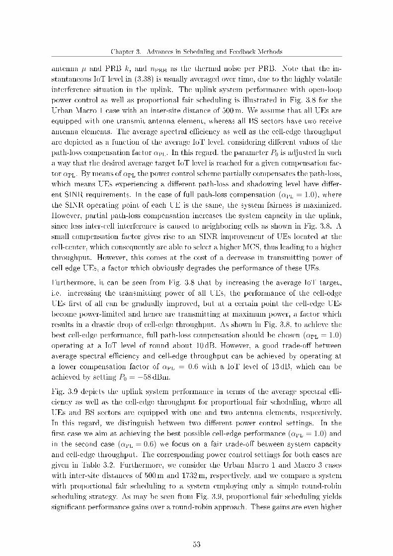
Chapter 3. Advances in Scheduling and Feedback Methods
antenna µ and PRB k, and nPRB as the thermal noise per PRB. Note that the in-stantaneous IoT level in (3.38) is usually averaged over time, due to the highly volatileinterference situation in the uplink. The uplink system performance with open-looppower control as well as proportional fair scheduling is illustrated in Fig. 3.8 for theUrban Macro 1 case with an inter-site distance of 500m. We assume that all UEs areequipped with one transmit antenna element, whereas all BS sectors have two receiveantenna elements. The average spectral e�ciency as well as the cell-edge throughputare depicted as a function of the average IoT level, considering di�erent values of thepath-loss compensation factor αPL. In this regard, the parameter P0 is adjusted in sucha way that the desired average target IoT level is reached for a given compensation fac-tor αPL. By means of αPL the power control scheme partially compensates the path-loss,which means UEs experiencing a di�erent path-loss and shadowing level have di�er-ent SINR requirements. In the case of full path-loss compensation (αPL = 1.0), wherethe SINR operating point of each UE is the same, the system fairness is maximized.However, partial path-loss compensation increases the system capacity in the uplink,since less inter-cell interference is caused to neighboring cells as shown in Fig. 3.8. Asmall compensation factor gives rise to an SINR improvement of UEs located at thecell-center, which consequently are able to select a higher MCS, thus leading to a higherthroughput. However, this comes at the cost of a decrease in transmitting power ofcell-edge UEs, a factor which obviously degrades the performance of these UEs.
Furthermore, it can be seen from Fig. 3.8 that by increasing the average IoT target,i.e. increasing the transmitting power of all UEs, the performance of the cell-edgeUEs �rst of all can be gradually improved, but at a certain point the cell-edge UEsbecome power-limited and hence are transmitting at maximum power, a factor whichresults in a drastic drop of cell-edge throughput. As shown in Fig. 3.8, to achieve thebest cell-edge performance, full path-loss compensation should be chosen (αPL = 1.0)
operating at a IoT level of round about 10 dB. However, a good trade-o� betweenaverage spectral e�ciency and cell-edge throughput can be achieved by operating ata lower compensation factor of αPL = 0.6 with a IoT level of 13 dB, which can beachieved by setting P0 = −58dBm.
Fig. 3.9 depicts the uplink system performance in terms of the average spectral e�-ciency as well as the cell-edge throughput for proportional fair scheduling, where allUEs and BS sectors are equipped with one and two antenna elements, respectively.In this regard, we distinguish between two di�erent power control settings. In the�rst case we aim at achieving the best possible cell-edge performance (αPL = 1.0) andin the second case (αPL = 0.6) we focus on a fair trade-o� between system capacityand cell-edge throughput. The corresponding power control settings for both cases aregiven in Table 3.2. Furthermore, we consider the Urban Macro 1 and Macro 3 caseswith inter-site distances of 500m and 1732m, respectively, and we compare a systemwith proportional fair scheduling to a system employing only a simple round-robinscheduling strategy. As may be seen from Fig. 3.9, proportional fair scheduling yieldssigni�cant performance gains over a round-robin approach. These gains are even higher
53

Advanced Transmission Schemes for the 4th Generation of Mobile Communication Systems
5 10 15 200.65
0.7
0.75
0.8
0.85
0.9
Average IoT [dB]
Avera
ge s
pectr
al effic
iency [bit/s
/Hz/s
ecto
r]
5 10 15 20100
150
200
250
300
350
400
Average IoT [dB]C
ell-
edge U
E thro
ughput [k
bps]
aPL
= 1.0
aPL
= 0.8
aPL
= 0.6
aPL
= 0.4
Figure 3.8.: Impact of the uplink power control on the system performance, considering di�erent
values of the path-loss compensation factor αPL. All results are given for the Urban
Macro 1 case with proportional fair scheduling.
Macro 1 Macro 30
0.1
0.2
0.3
0.4
0.5
0.6
0.7
0.8
0.9
1
Avera
ge s
pectr
al effic
iency [bit/s
/Hz/s
ecto
r]
Macro 1 Macro 30
50
100
150
200
250
300
350
400
450
500
550
Cell-
edge U
E thro
ughput [k
bps]
Proportional Fair, aPL
= 0.6
Proportional Fair, aPL
= 1.0
Round-robin, aPL
= 0.6
+41%
+51%
+42%
+98%
+72%+96%
+31%+17%
Figure 3.9.: Impact of di�erent power control settings with proportional fair scheduling on the
uplink system performance for the Urban Macro 1 and Macro 3 case. The given per-
centages denote the relative performance gains compared to a conventional LTE Re-
lease 8 system with round-robin scheduling.
than in the downlink, a factor which can be intuitively explained as follows. Since theround-robin scheduler schedules UEs independently of their current channel conditions,it may often happen that the channel of a scheduled UE to its serving BS is in a deepfade. This has a more noticeable e�ect on the uplink performance because UEs oftenbecome power-limited in the uplink. Thus, it is more likely that transmissions fail,leading to a higher performance degradation compared to the downlink.
Interestingly, we notice that the open-loop power control scheme has a smaller impact
54

Chapter 3. Advances in Scheduling and Feedback Methods
Table 3.2.: Power control parameter settings for Fig. 3.9
Intended purpose Urban Macro 1 Urban Macro 3
Trade-o� between system capacity αPL = 0.6, P0 = −58 dBm, αPL = 0.6, P0 = −60 dBm,
and cell-edge performance IoT = 13dB IoT = 2.7 dB
Achieving highest possible αPL = 1.0, P0 = −104 dBm, αPL = 1.0, P0 = −107 dBm,
cell-edge performance IoT = 10dB IoT = 1.5 dB
on the cell-edge performance for the Urban Macro 3 case compared to Macro 1. Thisindicates that, even with a decrease in the path-loss compensation factor, the UEslocated at the cell-edge have to transmit almost with maximum power due to the largeinter-site distance. Thus, the cell-edge performance is only marginally improving withincreasing path-loss compensation factor. However, a small compensation factor isstill bene�cial for cell-center UEs, which can improve their SINR due to the reducedinter-cell interference.
55


Chapter 4. Advanced Transmission Techniques for the Downlink
4. Advanced Transmission Techniques
for the Downlink
Multiple antenna transmission and reception is one of the key concepts for the nextgeneration of mobile communications systems, such as the 3GPP LTE, in order tomeet the ever increasing demand for higher data rates with the limited radio spectrumavailable for that purpose. A promising MIMO transmission scheme is the so-calledMU-MIMO technique, where multiple UEs can be served simultaneously on the samefrequency resources by means of proper precoding techniques [41,93]. MU-MIMO alsorepresents an intermediate step towards future CoMP systems, where di�erent BSscooperate with each other via a fast backhaul network in order to jointly transmit tomultiple UEs. Hence, CoMP transmission can be seen as a generalized MU-MIMOtechnique across multiple cooperating BS sites.
Lately, various MU-MIMO techniques have been intensively investigated in literaturedue to numerous advantages over conventional SU-MIMO schemes, such as the achieve-ment of the spatial multiplexing gain even without multiple antennas at the UE side,or the full exploitation of the spatial dimension of the downlink MIMO channel [41].In the case of SU-MIMO transmission, the BSs may be not able to fully exploit thespatial dimension of the downlink MIMO channel when the number of antennas at theUEs is smaller than at the BSs, which is usually the case for practical systems. Evenin the particular case, where both UEs and BSs are equipped with the same numberof antenna elements, SU-MIMO schemes face a spatial dimension loss for high correla-tion conditions at the BS side. The spatial dimension drawback of SU-MIMO systems,however, can be eliminated by the application of MU-MIMO due to the transmissionto spatially separated UE antennas [41].
As the interference suppression between simultaneously served UEs is carried out at theBS side, the availability of accurate channel knowledge is an indispensable prerequisitefor realizing MU-MIMO. In general, MU-MIMO schemes require perfect CSI at the BSside in order to achieve the full multiplexing gain [47]. While for SU-MIMO systems theaccuracy of the channel information does not a�ect the multiplexing gain, the feedbackrate per UE has to be increased linearly with the SINR to achieve this gain for MU-MIMO systems [53]. Hence, providing accurate channel information is considerablymore important for MU-MIMO than for SU-MIMO systems.
The information theoretic results in [17] have shown that dirty paper coding (DPC)proposed by Costa in [26] achieves the sum capacity of Gaussian MIMO broadcast
57

Advanced Transmission Schemes for the 4th Generation of Mobile Communication Systems
channels. However, the application of this scheme in real-world systems is usuallyimpractical due to the immense complexity involved with non-linear coding and theneed for perfect CSI of all channels at the transmitter side [54]. For that reason, a coupleof alternative linear precoding techniques of lower complexity have been developed inrecent years, see for example [13,22,94,95] and references therein. Such linear precodingtechniques are also capable of reaching sum capacity, especially in cases where UEs areequipped with more than one antenna element, which will be most likely in futuremobile communication systems.
Although simple MU-MIMO schemes with CQI feedback are partly speci�ed for state-of-the-art systems, such as LTE Release 8 [5], more sophisticated CQI and CSI-basedMU-MIMO schemes are currently being discussed for future mobile communicationstandards, because of their potential for providing signi�cantly higher spectral e�cien-cies [29, 57, 99]. Therefore, we propose in this chapter two novel downlink MU-MIMOschemes based on CQI as well as CSI feedback [36,38]. Both schemes contain SU-MIMOtransmission as a special case: hence are designed for dynamic switching between SU-and MU-MIMO transmission, a factor which provides additional degrees of freedom inthe scheduling that can be used to better adapt to the current channel conditions. Wethoroughly investigate both enhanced MU-MIMO schemes and compare the achievablesystem performance to our reference SU-MIMO system (cf. Chapter 3), as well as toa LTE Release 8 MU-MIMO scheme without SU-/MU-MIMO mode switching.
4.1. Enhanced MU-MIMO with CQI feedback
One of the most important requirements of future mobile communication standards isretaining backward compatibility with previous releases. For that reason and in orderto keep the amount of uplink feedback limited, we propose in the following an e�cientMU-MIMO scheme based on the LTE Release 8 standard feedback information. Thisstandard feedback information is not providing any additional MU-MIMO feedback in-formation such as information about precoders that should be used for simultaneouslyscheduled UEs, for example. Therefore, we also address the problem of how appro-priate MU-MIMO transmission parameters might be e�ciently obtained, based on theconventional LTE Release 8 SU-MIMO feedback, so that the BSs are able to performchannel-dependent scheduling and link adaptation for MU-MIMO transmission.
4.1.1. Identi�cation of feasible user combinations
The signal received on a single subcarrier by the i-th UE in the case of MU-MIMOtransmission may be expressed by
yi = Hi fi si +Hi
Kue∑n=1n6=i
fnsn + ii + ni, (4.1)
58

Chapter 4. Advanced Transmission Techniques for the Downlink
where we assume that the total transmitting power per subcarrier is equally distributedamong the simultaneously served UEs and that it is always constrained by
E
∥∥∥∥∥∥Kue∑n=1
fnsn
∥∥∥∥∥∥2 ≤ PT . (4.2)
In this regard, Kue denotes the number of simultaneously served UEs, Hi ∈ C[Nue×Mbs]
denotes the MIMO channel of UE i, fi ∈ C[Mbs×1] indicates one of the LTE Release 8precoding vectors used for transmit beamforming, si denotes the symbol transmittedby the i-th UE, and ii as well as ni cover the inter-cell interference and thermal noise,respectively. Furthermore, we assume throughout this thesis that UEs which havebeen selected by the scheduler for MU-MIMO transmission can only be served by asingle data stream in order to limit the signaling constraints in the downlink. As aconsequence, each BS is able to identify potential candidates for MU-MIMO trans-mission based on the reported RI, i.e. only UEs which have requested single streamtransmission (transmit beamforming) as transmission scheme are selected as possibleMU-MIMO candidates.
In order to mitigate the intra-cell interference in (4.1), we do not allow all possible UEcombinations to be served on the same resources. Depending on the reported PMI,appropriate UE combinations are chosen in such a way that the used precoding vectorsof the simultaneously served UEs ful�ll the following condition
0 ≤ δbeam ≤ ηbeam, δ beam =∣∣∣fHn fm∣∣∣ , n,m = 1, . . . , Kue, n 6= m, (4.3)
where η beam denotes the beam correlation threshold, which de�nes the maximum al-lowed correlation between the used precoding vectors. For minimizing the intra-cellinterference, η beam can be simply set to zero. However, this stringent condition maylimit the MU diversity, because it only can be ful�lled by a few precoding vector com-binations associated with the �nite LTE Release 8 codebook. Thus, the probability of�nding feasible UE combinations, which can be simultaneously scheduled on the samePRBs, is drastically reduced. On the other hand, when the value of η beam is increasedfor improving the MU diversity, the degree of intra-cell interference introduced by thesimultaneously served UEs may be increased as well. As a result, η beam has to bechosen in such a way that a reasonable trade-o� between MU diversity and intra-cellinterference is achieved.
4.1.2. MU-MIMO rate estimation
After dividing the UEs suited for MU-MIMO transmission into groups with precodersful�lling the constraint in (4.3), every BS �nally estimates the achievable MU-MIMOrates of all possible UE combinations based on the reported SU-MIMO CQI values
59

Advanced Transmission Schemes for the 4th Generation of Mobile Communication Systems
in order to perform channel-dependent scheduling, link adaptation, as well as SU-/MU-MIMO mode switching. For estimating the achievable MU-MIMO rates, wedetermine the corresponding MU-MIMO SINR values by empirically estimating theSINR loss compared to the SU-MIMO case. This loss is caused by the additionalintra-cell interference as well as by the fact that the transmitting power is split amongsimultaneously served UEs, where we assume an equal split-up. This is also con�rmedby Fig. 4.1, where we compare the SU-MIMO with the MU-MIMO SINR distribution.It can be seen from Fig. 4.1 that the impact of the intra-cell interference is SINRdependent. This is because, in general, the intra-cell interference is almost negligiblecompared to noise and inter-cell interference for low SINR values, whereas it is gettingmore signi�cant for high SINR values. As a result, we have empirically determinedlook-up tables for the MU-MIMO SINR loss, as illustrated in Fig. 4.1. Clearly, theMU-MIMO SINR loss depends on the correlation between the precoding vectors usedby the multiplexed UEs, i.e. a higher correlation gives rise to an increased intra-cellinterference.
Based on the estimated SINR values, the corresponding MU-MIMO rate for each UEcan then be calculated by means of the Shannon capacity formula, thus enablingchannel-dependent scheduling and link adaptation without any dedicated MU-MIMOfeedback. Note that the computational complexity with respect to UE grouping andachievable rate estimation is heavily dependent on the number of active UEs per BS.However, the additional computing time should be rather low, since on the one handoften only a few UEs per BS are active in practice, and on the other hand more powerfulhardware is generally used at the BS side for facilitating fast processing.
4.1.3. LMMSE detection for MU-MIMO transmission
In the following, we will extend the LMMSE detection technique, introduced in Sec-tion 2.2.5, aiming at eliminating the residual intra-cell interference in the case of MU-MIMO transmission. The intra-cell interference may be mitigated at the UE side whenthere are still additional degrees of freedom that can be exploited. This is the case, forexample, when each UE receives only a single data stream, but is equipped with morethan one receive antenna element. Thus, we rewrite the LMMSE equalization matrixin (2.24) as
WLMMSE,i = Rss (Hi fi)H(Hi fiRss (Hi fi)
H + diag(Rzz,i
))−1. (4.4)
The interference plus noise covariance matrix Rzz,i in (4.4) is given for the optimalcase, where the used precoders of the simultaneously served UEs are known, by
Rzz,i =Kue∑n=1n6=i
Hi fn E[sn s
Hn
]fHn H
Hi
︸ ︷︷ ︸intra-cell interference
+E[ii i
Hi
]+ E
[ni n
Hi
], (4.5)
60

Chapter 4. Advanced Transmission Techniques for the Downlink
−10 −5 0 5 10 15 200
0.1
0.2
0.3
0.4
0.5
0.6
0.7
0.8
0.9
1
SINR [dB]
Cum
ulat
ive
dist
ribut
ion
func
tion
MU−MIMOSU−MIMO
−10 −5 0 5 10 15 202.5
3
3.5
4
4.5
5
SU−MIMO SINR [dB]E
stim
ated
MU
−M
IMO
SIN
R lo
ss [d
B]
δbeam
= 0
0 < δbeam
≤ 0.3
0.3 < δbeam
≤ 0.5
SINR loss
Figure 4.1.: Distribution of the SINR values for SU-MIMO as well as for MU-MIMO transmis-
sion only and the empirically determined MU-MIMO SINR loss as a function of
the SU-MIMO SINR values for di�erent beam correlations.
Clearly, the receiver performance may be improved by taking the occurring intra-cell interference in (4.5) into account. However, in order to mitigate the intra-cellinterference, knowledge about used precoding vectors of all simultaneously served UEsis required, leading to an additional downlink signaling overhead.
4.2. Enhanced MU-MIMO with CSI feedback
In contrast to CQI-based MU-MIMO schemes, where the interference suppression atthe BS side is rather limited due to the �nite precoder codebook, MU-MIMO schemeswith more sophisticated as well as resource-e�cient CSI feedback may further improvethe system performance. This is due to the fact that with more accurate downlinkchannel knowledge at the BS side the precoders can be individually designed in orderto better mitigate the intra-cell interference caused by serving multiple UEs at the sametime and on the same PRBs. For that reason, we propose an enhanced MU-MIMOscheme in combination with our novel CSI feedback method presented in Section 3.3.2,where each UE reports a quantized version of its estimated downlink channel as wellas information of its interference situation back to its serving BS. In the following,we will address the problem of how precoders for MU-MIMO transmission with CSIfeedback can be e�ciently designed in order to suppress the intra-cell interference. Inthis regard, we will put the focus on linear precoding techniques, due to their lowercomplexity and their practicability compared to non-linear techniques such as DPC.
We emphasize again that we also assume for the CSI-based MU-MIMO scheme that
61

Advanced Transmission Schemes for the 4th Generation of Mobile Communication Systems
each UE will be only served with one data stream in the case of MU-MIMO transmissionin order to preserve some degrees of freedom to cancel residual intra-cell interferenceat the UE side as well as to avoid additional downlink signaling.
4.2.1. Block diagonalization precoding
The linear block diagonalization (BD) precoding technique for downlink MU-MIMOsystems was �rst proposed in [92]. This precoding technique, which allows UEs tobe equipped with more than one antenna element, can be seen as an extension of thesimple ZF precoding [94]. The fundamental idea of BD is that the precoding matrix ischosen in such a way that all intra-cell interference is zero provided that perfect CSIis available at the BSs. In order to ful�ll this requirement, the precoding vector foreach UE has to lie in the null space of all other simultaneously served users' channelmatrices.
The term Hi
∑Kuen=1n6=i
fnsn in (4.1) represents the intra-cell interference for the i-th UE.
Thus, the BD precoding vector is designed such that
Hi fn = 0 ∀n 6= i, 1 ≤ n, i ≤ Kue. (4.6)
To satisfy the constraint in (4.6), fn has to lie in the null space of
Hn =[HT
1 · · · HTn−1 HT
n+1 · · · HTKue
]T. (4.7)
Let Gn denote the rank of Hn ∈ C[(Kue−1)Nue×Mbs]. Then, by means of the singularvalue decomposition of
Hn = Un Dn
[V
(1)
n V(0)
n
]H, (4.8)
we obtain the last right (Mbs − Gn) singular vectors V(0)
n ∈ C[Mbs×(Mbs−Gn)
], which
form an orthogonal basis for the null space of Hn. However, as shown in [92, 94] V(0)
n
only exist for the conditionMbs ≥ KueNue. (4.9)
The e�ective channel of the n-th UE after eliminating the intra-cell interference is given
by Hn V(0)
n ∈ C[Nue×(Mbs−Gn)
]. This e�ective channel can be seen as a conventional SU-
MIMO channel and therefore the precoding vector fn, maximizing the received SINRsubject to the zero intra-cell interference constraint in (4.6), may be expressed by
fn = V(0)
n vn,e�, (4.10)
where vn,e� is the singular vector of Vn,e� corresponding to the strongest singular valueof the e�ective channel matrix
Hn,e� = Hn V(0)
n = Un,e�Dn,e�VHn,e�. (4.11)
62
Chapter 4. Advanced Transmission Techniques for the Downlink
Note that the zero intra-cell interference constraint in (4.6) can be only achieved withperfect channel knowledge at the BS side. In the case of limited feedback, when onlythe quantized versions of the channel matrices are available, there will be still residualintra-cell interference, resulting in a performance degradation.
4.2.2. Regularized block diagonalization precoding
A more generalized approach for designing MU-MIMO precoding matrices is the so-called regularized block diagonalization (RBD) technique [95]. In contrast to conven-tional BD as studied in the previous section, RBD allows arbitrary antenna con�g-urations at the simultaneously served UEs and is hence not limited to cases whereMbs ≥ KueNue. In order to facilitate a general precoding design, the calculation ofthe precoding vector is split into two steps. In the �rst step the intra-cell interferenceis suppressed, whereas in the second step the system performance is optimized underthe assumption that the MU-MIMO channel is decomposed into a set of parallel in-dependent SU-MIMO channels. Let us denote ytotal as the received vector of all Kue
simultaneously served UEs de�ned by
ytotal =[yT1 · · · yTKue
]T= HtotalFa,totalFb,total stotal + itotal + ntotal, (4.12)
with Htotal = [ HT1 · · · HT
Kue]T ∈ C[KueNue×Mbs] as the combined channel matrix,
Fa,total = [ Fa,1 · · · Fa,Kue] ∈ C[Mbs×(KueMbs)] and
Fb,total =
fb,1 0 0
0. . . 0
0 0 fb,Kue
∈ C[(KueMbs)×Kue] (4.13)
as the precoding matrices containing all components of the individual precoders. Fur-thermore, stotal = [ s1 · · · sKue
]T ∈ C[Kue×1] denotes the stacked symbol vector,
and itotal = [ iT1 · · · iTKue]T ∈ C[(KueNue)×1] as well as ntotal = [ nT1 · · · nTKue
]T ∈C[(KueNue)×1] indicate the stacked inter-cell interference and noise vector respectively.As it can be seen from (4.12) the individual precoding vector of the i-th UE is factorizedby
fi = Fa,i fb,i, (4.14)
in order to facilitate the two-stage design approach. In this regard, the precodingmatrix Fa,total is determined by solving the following optimization according to [95]
Fa,total = minFa,total
E
Kue∑i=1
∥∥∥HiFa,i
∥∥∥2F
+ ‖ntotal‖2 + ‖itotal‖2 , (4.15)
where
HiFa,i =[HT
1 · · · HTi−1 HT
i+1 · · · HTKue
]TFa,i (4.16)
63

Advanced Transmission Schemes for the 4th Generation of Mobile Communication Systems
denotes the intra-cell interference caused by the UE i. The squared Frobenius norm∥∥∥HiFa,i
∥∥∥2Fis equivalent to the power of the intra-cell interference observed by the
UEs scheduled on the same PRBs as UE i. Thus, Fa,total is designed to minimize thepower of the intra-cell interference plus noise and inter-cell interference. Note that weextend the original optimization criterion of the RBD approach proposed in [95] byalso taking the prevalent inter-cell interference in (4.15) into account. Thus, accordingto the derivation in [95], the precoding matrix
Fa,i = Vi
(DT
i Di +KueNue IMbs
(E[‖ntotal‖2
]+ E
[‖itotal‖2
]))−1/2(4.17)
solves the minimization in (4.15), where Vi and Di can be obtained from the singular
value decomposition of Hi = Ui Di VH
i . Under the assumption that the total intra-cell interference can be suppressed by Fa,total, the MU-MIMO channel is e�ectivelytransformed into multiple parallel independent SU-MIMO channels. For maximizingthe received SINR of the i-th e�ective SU-MIMO channel He�, the precoding vectorfb,i may be chosen as the right singular vector of
He� = HiFa,i = Ui,e�Di,e�VHi,e�, (4.18)
corresponding to the strongest singular value.
4.2.3. Precoding based on multi-user eigenmode transmission
Another e�cient linear precoding technique which achieves a large fraction of the DPCcapacity, under the assumption of perfect channel knowledge, has recently been pro-posed in [13]. This precoding technique, known as multi-user eigenmode transmis-sion (MET), is based on the BD approach. The calculation of the MET precodingmatrix can be summarized as follows. First of all, the i-th UE channel can be de-composed by means of a singular value decomposition as Hi = UiDiV
Hi , where Di
contains the singular values of Hi sorted in descending order. Let us assume for thetime being that the Hermitian transposition of the leftmost column of Ui, denotedby uHi,1, is used for detection. Then, taking into account that only one data streamper simultaneously served UE is transmitted, the received signal of the i-th UE afterdetection is given by [13]
ri = uHi,1 yi = gi fi si + gi
Kue∑n=1n6=i
fn sn + uHi,1 ii + uHi,1 ni, (4.19)
where gi can be expressed by
gi = di,1 vHi,1, (4.20)
64

Chapter 4. Advanced Transmission Techniques for the Downlink
with di,1 as the strongest singular value of Di, and vi,1 as the leftmost column of theright singular vector matrix Vi. Similar to the BD method, the zero-forcing conditionis applied, so that the precoding vector fi has to lie in the null space of
Hi =[gT1 · · · gTi−1 gTi+1 · · · gTKue
]T. (4.21)
The zero intra-cell interference constraint can be satis�ed by the matrix V(0)
i , containingthe last right (Mbs−Gn) singular vectors, where Gn denotes the rank of Hi. The matrix
V(0)
i is de�ned by singular value decomposition of Hi
Hi = Ui Di
[V
(1)
i V(0)
i
]H, (4.22)
yielding
Hi V(0)
i = 0. (4.23)
However, to ful�ll this zero intra-cell interference constraint the number of transmittedeigenmodes of all simultaneously served UEs has to be smaller or equal to the numberof transmit antenna elements at the BS side [13]. Note that this constraint is lessstringent than the BD constraint in (4.6), whereMbs ≥ KueNue. Motivated by the factthat
gi fn = gi V(0)
n vn,e� = 0, (4.24)
for n 6= i and any choice of vn,e�, vn,e� may be chosen as the singular vector of Vn,e�
corresponding to the strongest singular value of the e�ective channel matrix
Hn,e� = gn V(0)
n = Un,e�Dn,e�VHn,e�. (4.25)
Thus maximizing the received SINR. In the case of imperfect CSI at the BS side,the MET precoding vector is still determined based on the zero intra-cell interferenceconstraint in (4.23). Clearly, the term in (4.23) is then non-zero, thus there will still beresidual intra-cell interference compared to the ideal case with perfect CSI. In order tomitigate the residual intra-cell interference, the UEs may make use of multiple receiveantennas, which provide additional degrees of freedom. As a consequence, instead ofusing the left singular vector for detection in (4.19), the LMMSE equalization matrix in(4.4) may be employed to e�ciently mitigate the e�ects of the intra-cell interference.Note that a crucial prerequisite for proper detection according to (4.4) is that theprecoders of the simultaneously served UEs have to be signaled by the BSs.
4.3. MU-MIMO proportional fair scheduling
Based on the feedback information reported by the UEs, the BSs perform frequency-selective proportional fair scheduling according to the algorithm presented in Sec-tion 3.2. In this regard, the scheduler determines the transmission mode, precoding
65

Advanced Transmission Schemes for the 4th Generation of Mobile Communication Systems
weights, as well as MCSs to be used by the UEs assigned for data transmission. Fur-thermore, the scheduler facilitates dynamic switching between SU- and MU-MIMOtransmission by selecting for each PRB one of the transmission schemes depending onthe respective scheduling priorities. In the case of MU-MIMO transmission, the num-ber of UEs which can be simultaneously served on the same PRBs is generally limitedto the number of transmit antennas Mbs at the BS. However, as the number of activeUEs assigned to a certain BS typically exceedsMbs the scheduler has to select a subsetof UEs allowed for MU-MIMO transmission. In this regard, we restrict the maximalnumber of simultaneously served UEs on the same PRB to Kue = 2. In this way, notonly may additional degrees of freedom for mitigating the residual intra-cell interfer-ence at the UE side be preserved; also, a greater fraction of the available transmittingpower to all multiplexed UEs can be provided.
For the CQI-based feedback method, the UEs which have requested transmit beam-forming as transmission scheme are preselected as described above, and for all UEcombinations of interest the corresponding MU-MIMO rates are estimated for eachPRB by means of the Shannon capacity. By contrast, the transmission scheme selec-tion complexity is considerably increased for CSI-based MU-MIMO due to the largernumber of degrees of freedom. In order to reduce the computational e�ort, potentialMU-MIMO candidates are identi�ed based on the SU-MIMO transmission scheme se-lection according to (3.37) (cf. Section 3.3.2.4). Similar to the CQI-based method,the BS selects only UEs associated with transmit beamforming as possible MU-MIMOcandidates. However, the BS still has to determine for this subset of UEs all possibleUE combinations and their respective MU-MIMO rates. Recently, several suboptimalUE selection algorithms have been proposed [39,66,87], in order to avoid the exhaustivecalculation of all precoding weights, required to estimate the corresponding MU-MIMOrates. However, even with such low complexity selection algorithms, a large amountof singular value decompositions is still necessary, and the minor reduction in com-putational complexity usually does not justify the resulting performance loss. As aconsequence, we do not further restrict the possible UE combinations in the following.Moreover, it should be emphasized that fast processing with respect to precoder calcu-lation and achievable MU-MIMO rate estimation should be feasible at the BS side evenwithout such selection algorithms, although the computing time is heavily dependenton the number of active UEs per BS.
The underlying proportional fair scheduling procedure supporting MU-MIMO trans-mission is shown in Fig. 4.2. In a �rst step, the scheduler determines for each UEand PRB the corresponding SU-MIMO proportional fair priorities according to (3.3).Then, the MU-MIMO scheduling priority, given by the sum of the proportional fairpriorities of the various UEs to be scheduled on the same PRBs, is calculated by
GKMU,b (t) =∑
i∈KMU
G(MU)i,b (t) =
∑i∈KMU
R(MU)i,b (t)
TαPFi (t)
, (4.26)
with KMU as a set of simultaneously served UEs, R(MU)i,b (t) as the MU-MIMO rate
66

Chapter 4. Advanced Transmission Techniques for the Downlink
Calculation of the achievable SU-MIMOrates over the whole bandwidth
Transmitbeamforming rate
higher?
Resource allocation
Calculation of the SU-MIMOproportional fair metrics
Select transmit beamforming asSU-MIMO transmission scheme
Determine feasible UE combinations
Select spatial muliplexing asSU-MIMO transmission scheme
yes no
Transmitbeamforming
selected?
No MU-MIMO transmission allowed
yes no
Calculation of MU-MIMO proportionalfair metrics for all UE combinations
Comparison between the sum of individual MU-MIMOproportional fair metrics and the SU-MIMO one
SU-MIMO mode
MU-MIMO mode
Scheduling
Figure 4.2.: Proportional fair scheduling procedure with MU-MIMO support.
of the i-th UE, considering that the UEs (KMU\ i) are scheduled on the same b-thPRB. For all feasible UE combinations, the MU-MIMO scheduling priority in (4.26)is determined, and for each PRB the combination which maximizes the weighted sumrate is selected. Finally, the scheduler compares the highest SU-MIMO priority tothe highest MU-MIMO priority for each PRB. If the SU-MIMO priority is larger,then, depending on the previous SU-MIMO transmission scheme selection process,either transmit beamforming or spatial multiplexing is selected, otherwise MU-MIMOtransmission is preferred.
In summary, our enhanced downlink MU-MIMO schemes take into account dynamicSU/MU-MIMO transmission mode switching and are based on our novel low-rate CQIas well as CSI feedback methods introduced in Chapter 3. We have demonstrated howappropriate MU-MIMO transmission parameters might be e�ciently obtained basedon the available SU-MIMO feedback information as well as how potential MU-MIMOcandidates are identi�ed and selected at the BS side. Finally, we have proposed a novelMU-MIMO proportional fair scheduling procedure which is capable of dynamicallyswitching between SU- and MU-MIMO transmission modes.
67

Advanced Transmission Schemes for the 4th Generation of Mobile Communication Systems
4.4. MU-MIMO system performance
In this section we demonstrate the system performance of the proposed MU-MIMOschemes with CQI as well as CSI feedback for various scenarios and parameter settings.As outlined in Section 3.4.1, we consider a fair performance comparison between bothMU-MIMO schemes by spending approximately the same amount of feedback bits persubband (cf. Table 3.1 in Section 3.4.1). For the following system-level simulationresults, we assume that the scheduling is always proportional fair and that each BSsector is equipped with four transmit antenna elements, whereas each UE has only tworeceive antenna elements. Furthermore, we distinguish between two di�erent fadingcorrelation scenarios at the BS side, summarized in Table 4.1. We also focus on theUrban Macro 1 case, as speci�ed in [1], with an inter-site distance of 500m. If notstated otherwise, there are always ten uniformly distributed UEs in each sector onaverage and we consider a LMMSE receiver according to (4.4), assuming that the usedprecoders of the simultaneously served UEs are known.
Fig. 4.3 shows the average spectral e�ciency as a function of the number of active UEsper BS sector for the enhanced MU-MIMO system with CQI feedback, considering ahigh correlation scenario and di�erent values of the beam correlation threshold ηbeam.Clearly, the average spectral e�ciency can be improved with more active UEs per BSsector due to the increased MU diversity. Thus, the scheduler is able to better exploitthe spatial separability among the active UEs, i.e. more UE combinations can befound which do not cause severe intra-cell interference if scheduled simultaneously onthe same PRB. As expected, the system performance of the CQI-based MU-MIMOscheme is heavily dependent on the beam correlation threshold η beam. For minimizingthe intra-cell interference, η beam can be set to zero, a factor that, however, gives riseto a strictly limited choice of feasible precoding vector combinations. This leads to arelatively poor system performance in situations where only few UEs are active. But ata certain point, with su�cient UEs per BS, the MU diversity can be better exploited,since the stringent condition η beam = 0 can be ful�lled by more UEs, resulting in aperformance enhancement. On the other hand, it can be observed that for the caseη beam →∞, where the scheduler is allowed to make use of all possible precoding vectorcombinations, the intra-cell interference thus caused becomes the limiting factor. Thus,the scheduler must aim at �nding a good trade-o� between MU diversity and introducedintra-cell interference. This can be accomplished by setting η beam = 0.5, as illustratedin Fig. 4.3. In addition to the results where the used precoders of the simultaneouslyserved UEs are known for improving LMMSE receiver performance, Fig. 4.3 also showsthe performance loss for the case that these precoders are not known at the receiverside. The corresponding performance loss in terms of average spectral e�ciency isabout 7%, assuming ηbeam = 0.5 and ten UEs per BS sector.
Fig. 4.4 and 4.5 show the system performance comparison between the enhanced MU-MIMO schemes with CQI and CSI feedback for an average and highly correlated fading
68

Chapter 4. Advanced Transmission Techniques for the Downlink
Table 4.1.: Spatial correlation scenarios at the BS side
Parameter Average correlation High correlation
Angle of departure spread 15 degrees 5 degrees
BS antenna spacing 10 times wavelength 0.5 times wavelength
1 2 4 6 8 10 12 14 16 18 20
1.5
1.6
1.7
1.8
1.9
2
2.1
2.2
2.3
Ave
rage
spe
ctra
l effi
cien
cy [b
it/s/
Hz/
sect
or]
Number of active UEs per BS sector
ηbeam
→ ∞, LMMSE w/ precoder knowledge
ηbeam
= 0.5, LMMSE w/ precoder knowledge
ηbeam
= 0.5, LMMSE w/o precoder knowledge
ηbeam
= 0.3, LMMSE w/ precoder knowledge
ηbeam
= 0, LMMSE w/ precoder knowledge
Figure 4.3.: Impact of the number of active UEs per BS sector on the average spectral e�ciency
for CQI-based MU-MIMO, considering a high correlation scenario and di�erent
values of the beam correlation threshold η beam. For η beam = 0.5, both cases,
LMMSE receiver with and without intra-cell interference mitigation, are shown.
scenario, where our LTE Release 8 based baseline system with CQI-based SU-MIMOsupport only is used as a reference. In addition, the performance of a simple LTE Re-lease 8 MU-MIMO scheme according to [5] without support of dynamic SU-/MU-MIMOmode switching is also illustrated in Fig. 4.4 and 4.5. Interestingly, the performanceof MU-MIMO is heavily dependent on the fading correlation at the BS side. For asmall angular spread as well as antenna spacing, the signals tend to be strongly corre-lated, hence beamforming becomes more e�ective. In particular, this is important forMU-MIMO, since closely spaced antenna elements achieve a better nulling by formingsharper beams, i.e. the nulls formed towards simultaneously served UEs considerablyreduce the intra-cell interference. As can be as seen from Fig. 4.4 and 4.5, MU-MIMOmay only provide minor gains in the order of 10% and 9% for the average spectrale�ciency and cell-edge throughput for an average correlation scenario, whereas thesegains can be boosted up to 28% and 14% for a high correlation scenario. Note thatthese MU-MIMO gains are achieved with a low-rate feedback channel (cf. Table 3.1in Section 3.4.1), i.e. without increasing the uplink feedback load compared to theCQI-based SU-MIMO reference. Furthermore, we note that with a more generalizedprecoding approach, such as RBD or MET, the system performance can be improvedcompared to the simpler BD approach. By comparing the performance of both en-
69

Advanced Transmission Schemes for the 4th Generation of Mobile Communication Systems
(1) (2) (3) (4) (5)0
0.5
1
1.5
2
2.5
Scheme
Avera
ge s
pectr
al effic
iency [bit/s
/Hz/s
ecto
r]
(1) (2) (3) (4) (5)0
100
200
300
400
500
600
700
800
900
1000
SchemeC
ell-
edge U
E thro
ughput [k
bps]
(1) LTE Release 8 CQI MU-MIMO
(2) Enhanced CQI MU-MIMO
(3) Enhanced CSI MU-MIMO with BD
(4) Enhanced CSI MU-MIMO with RBD
(5) Enhanced CSI MU-MIMO with MET
LTE Release 8 CQI SU-MIMO
+8%+1%
+5%
+8% +7% +8% +10%
+3%
1%+9%
Figure 4.4.: System performance comparison between the enhanced MU-MIMO schemes and
a LTE Release 8 MU-MIMO scheme, considering an average correlation scenario
according to Table 4.1. The given percentages denote the relative performance
gains compared to our CQI-based SU-MIMO reference system.
(1) (2) (3) (4) (5)0
0.5
1
1.5
2
2.5
Scheme
Avera
ge s
pectr
al effic
iency [bit/s
/Hz/s
ecto
r]
(1) (2) (3) (4) (5)0
100
200
300
400
500
600
700
800
900
1000
Scheme
Cell-
edge U
E thro
ughput [k
bps]
(1) LTE Release 8 CQI MU-MIMO
(2) Enhanced CQI MU-MIMO
(3) Enhanced CSI MU-MIMO with BD
(4) Enhanced CSI MU-MIMO with RBD
(5) Enhanced CSI MU-MIMO with MET
LTE Release 8 CQI SU-MIMO+2%
+14%
+21%
+28%
+12% +10%+14%
+4%
+10%
+5%
Figure 4.5.: System performance comparison between the enhanced MU-MIMO schemes and a
LTE Release 8 MU-MIMO scheme, considering a high correlation scenario according
to Table 4.1. The given percentages denote the relative performance gains compared
to our CQI-based SU-MIMO reference system.
hanced MU-MIMO schemes, it can be seen that the CSI-based scheme with METprecoding yields slightly higher performance gains than the CQI-based scheme. Thiscan be explained by the increased �exibility at the BS side with CSI feedback, wherethe precoders can be individually designed for each UE. Finally, we note that bothproposed enhanced MU-MIMO schemes outperform the simple LTE Release 8 basedMU-MIMO scheme.
70

Chapter 4. Advanced Transmission Techniques for the Downlink
1 2 5 10 25 501
1.2
1.4
1.6
1.8
2
2.2
2.4
2.6
Reporting subband size [PRBs]
Avera
ge s
pectr
al effic
iency [bit/s
/Hz/s
ecto
r]
1 2 5 10 25 500
100
200
300
400
500
600
700
800
900
Reporting subband size [PRBs]C
ell-
edge U
E thro
ughput [k
bps]
CSI feedback
CQI feedback
MU-MIMO MU-MIMO
SU-MIMO
SU-MIMO
Figure 4.6.: Impact of the subband size on the system performance for SU- as well as enhanced
MU-MIMO with CQI and CSI feedback, considering a high correlation scenario.
For the CSI-based MU-MIMO results MET precoding is assumed.
Fig. 4.6 shows the impact of the subband size on the system performance in a highcorrelation scenario for the enhanced CQI- and CSI-based MU-MIMO schemes, whereMET precoding is considered in the case of CSI feedback. For comparison, we also il-lustrate the performance of the CQI- and CSI-based SU-MIMO reference system. Thesubband size ranges from one�corresponding to the situation where for each PRB afeedback report is generated�to 50, where a single wideband report is fed back for thetotal number of OFDM subcarriers. Obviously, by reducing the reporting granularitythe system performance becomes steadily better. This is because the channel feed-back re�ects much better the current channel and interference variations with a �nerresolution in the frequency domain, thus leading to an improved frequency-domainscheduling. However, this comes at the cost of an increased uplink overhead. Anotherinteresting e�ect which can be observed in Fig. 4.6 is that the CSI-based feedbackmethod outperforms the CQI-based method for smaller subband sizes, whereas, if thesubband size gets larger, it is exactly the other way around. This indicates that theCSI-based method is more susceptible to the accuracy of the reported channel informa-tion. However, on the other hand it yields higher gains in the case that more accuratechannel information is available at the BS side due to the generalized precoding design,a factor that leads to an improved interference suppression.
In Fig. 4.7, a closer look is taken at the impact of the number of active UEs per BSsector on the system performance. Both the performance of SU-MIMO as well as of theenhanced MU-MIMO schemes are illustrated, assuming a high spatial correlation atthe BS side. As already seen in Fig. 4.3, the average spectral e�ciency can be improvedwith increasing number of active UEs due to the higher MU diversity in that case. Bycontrast, however, the cell-edge throughput decreases with increasing number of active
71

Advanced Transmission Schemes for the 4th Generation of Mobile Communication Systems
2 4 6 8 101
1.2
1.4
1.6
1.8
2
2.2
Avera
ge s
pectr
al effic
iency [bit/s
/Hz/s
ecto
r]
Number of active UEs per BS sector2 4 6 8 101
500
1000
1500
2000
2500
3000
Cell-
edge U
E thro
ughput [k
bps]
Number of active UEs per BS sector
CSI feedback
CQI feedback
SU-MIMO
MU-MIMO
MU-MIMOSU-MIMO
Figure 4.7.: Impact of the number of active UEs per BS sector on the system performance for
SU- as well as enhanced MU-MIMO with CQI and CSI feedback, considering a
high correlation scenario. For the CSI-based MU-MIMO results MET precoding is
assumed.
0
10
20
30
40
50
60
70
80
90
100
Sel
ectio
n pr
obab
ility
[%]
CQI SU−MIMO onlyCSI SU−MIMO onlyEnhanced CQI MU−MIMOEnhanced CSI MU−MIMO
SU spatial multiplexing MU transmit beamformingSU transmit beamforming
Figure 4.8.: Transmission scheme selection probabilities for SU- as well as enhanced MU-MIMO
with CQI and CSI feedback, considering a high correlation scenario. For the CSI-
based MU-MIMO results MET precoding is assumed.
UEs, because fewer PRBs can be assigned by the frequency-selective proportional fairscheduler to UEs located at the cell-edge. Similar to the results shown above, it can bealso seen from Fig. 4.7 that the CSI-based method performs slightly better than theCQI-based one.
Finally, Fig. 4.8 depicts the probabilities that a certain transmission scheme is selected
72

Chapter 4. Advanced Transmission Techniques for the Downlink
for both the CQI-based and the CSI-based feedback method, with and without en-hanced MU-MIMO support. Again, we focus on the high correlation case, as de�nedin Table 4.1. It can be seen that the probability for selecting one of the SU-MIMOtransmission schemes, and in particular for selecting spatial multiplexing, is signi�-cantly reduced in case of MU-MIMO support for both CQI and CSI feedback. Thisis because the scheduler is in most cases able to �nd spatially separated UEs for si-multaneous transmission on the same PRBs. In this case, the spatial correlation ofthe channel can be reduced compared to the SU-MIMO case by transmitting two datastreams to spatially separated UE antennas. As a result, in most of the cases a higherthroughput can be achieved with MU-MIMO transmission, even if the transmittingpower has to be shared between co-served UEs.
73


Chapter 5. Advanced Transmission Techniques for the Uplink
5. Advanced Transmission Techniques
for the Uplink
Recently, BS cooperation techniques�also known under the term CoMP�have at-tracted a lot of attention, because of their potential for realizing a signi�cant increasein spectral e�ciency. Since current cellular networks, operating with universal fre-quency reuse, are in general interference-limited, techniques that mitigate the e�ects ofinter-cell interference caused by adjacent site transmissions can considerably improvethe system performance, in particular for more dense network deployments in urbanareas [15]. However, as will be shown later, the performance enhancement with CoMPconcepts requires communication between the cooperating BSs, resulting in challengingbackhaul capacity requirements.
In general, the various CoMP schemes can be classi�ed according to the extent ofcooperation between di�erent BSs [69]. On the one hand, there are the full complexityjoint signal processing schemes, where user data or (partially) processed transmit orreceive signals are exchanged among BSs. In the downlink, this concept could be usedfor realizing joint transmission, for example, where one UE is simultaneously served bymultiple BSs [51, 55]. In this way, not only the signal strength of the signal intendedfor the respective UE may be considerably improved, but at the same time also theinterference originating from transmissions to other UEs can be reduced, thus actuallyleading to a two-fold performance gain. Since the exclusive assignment of certain radioresources in multiple cooperating cells to one particular UE would come along witha loss of spectral e�ciency: however, in general multiple UEs may be jointly servedby the set of cooperating cells at the same time by employing well-known MU-MIMOtransmission schemes (cf. Chapter 4) across the various cells. In the uplink, in contrast,one may perform joint detection by evaluating not only the signal received by a singleBS, but rather jointly process the signals received by multiple cooperating BSs in anappropriate way, thus improving the signal detection [37, 50, 103]. Similar to jointtransmission in the downlink, a two-fold gain can be obtained this way. On the onehand, we have an e�ective increase of the number of receive antennas and hence canbene�t from higher spatial diversity, while on the other hand signals which representinterference in conventional systems are now treated as useful signals and contributeto an increased detection probability.
In contrast to the joint signal processing schemes, BSs may also cooperate in a some-what looser way in order to ease the backhaul capacity requirements [15, 31, 73]. For
75

Advanced Transmission Schemes for the 4th Generation of Mobile Communication Systems
example, in the uplink the resource allocation between adjacent BSs may be coordi-nated in such a way that cell-edge UEs of neighboring cells are not assigned to thesame radio resources, thus avoiding high inter-cell interference situations [35].
Some recent results have revealed the fundamental potential of CoMP schemes andit has been shown that in principle tremendous performance gains may be realized inthis way [55, 69, 103]. In practical systems, however, the achievable gains generallyare expected to be well below the theoretical limits, yet signi�cant [69]. This is dueto various practical issues such as restricted subsets of BSs that could cooperate, asthey should be located in close geographical vicinity. Another example is channelestimation errors and the general di�culty of performing accurate multi-cell channelestimation, as well as synchronization challenges. In addition to this, e�cient jointreception schemes in the uplink, for example, generally require accurate multi-cell CSIat the BS side. Moreover, these schemes make high demands on the backhaul capacity,since the received baseband signals of all cooperating BSs have to be exchanged forcoherent detection. Apart from this, the cooperation stage generally adds an additionaldelay to the data processing and thus increases the overall latency. Therefore, a ratherpromising approach for the short-term is to support only cooperation between thevarious sectors of the same BS site, but not between di�erent sites [74]. In this way,many of the general problems outlined above can easily be overcome, because all BSs ofthe same site are usually integrated into the same physical device and no transmissionvia the backhaul network is necessary. In the case of LTE-A, di�erent BSs generallymay cooperate with each other using the X2-interface [8]. This interface, however,is only a logical one, and therefore it is not assured that there is always a direct linkbetween two cooperating sites. For that reason, the network structure may also have tobe adjusted by operators in order to enable the e�cient application of CoMP schemesin practice.
In this chapter, we �rst study in Sections 5.1 and 5.2 various CoMP schemes for theuplink of cellular networks, where limited data is exchanged between cooperating BSsfor the purpose of both multi-cell interference coordination and multi-cell interferenceprediction. The level of uplink BS cooperation is then increased in Section 5.3, wherefull complexity joint signal processing schemes are investigated, particularly with regardto reduced backhaul capacity requirements.
5.1. Inter-cell interference coordination
In current cellular systems, BSs usually perform independent scheduling without coor-dinating the resource allocation among di�erent cells. Moreover, these systems operatewith universal frequency reuse in order to exploit the whole frequency bandwidth ineach cell. This, however, often leads to severe inter-cell interference caused by simulta-neous transmissions scheduled on the same frequency resources by nearby BSs, partic-ularly limiting the performance of UEs located at the cell-edge, which su�er most from
76
Chapter 5. Advanced Transmission Techniques for the Uplink
inter-cell interference. In order to partially mitigate this problem, a cooperation amongadjacent BSs may be employed for coordinating the inter-cell interference. Such inter-ference coordination techniques have recently attracted a lot of research attention dueto their potential to realize signi�cant performance gains compared to non-cooperativesystems [11,15].
The basic idea of interference coordination in general is to let di�erent BSs cooperatewith each other in order to control and account for the inter-cell interference originat-ing from the corresponding cooperating cells. This may be done in either a static ordynamic manner. With a static approach, there are usually some pre-con�gured restric-tions regarding the resource allocation, for example, that on some frequency resourcesno cell-edge UEs may be scheduled, as it is the case for static fractional frequencyreuse [107]. With a dynamic scheme, in contrast, such restrictions are dynamically de-termined on a much shorter time scale by taking the instantaneous channel conditionsinto account. In the case of dynamic fractional frequency reuse, for instance, therewould be only restrictions on certain frequency resources when high interference is ex-pected, see for example [32, 67]. Clearly, dynamic interference coordination generallyshould lead to a better performance than static approaches, but this comes at the costof a higher complexity and possibly a higher backhaul load [15].
In the following section, we will look into a CoMP scheme where adjacent BSs exchangeinformation in order to coordinate the resource allocation to avoid severe inter-cellinterference. More precisely, we propose an e�cient method for dynamic interferencecoordination based on the standardized high interference indicator (HII) [8, 11, 15].However, it is clear that in principle even higher performance gains may be expectedif instead of coordinating the scheduling processes of adjacent BSs, the radio resourceallocation would be done jointly for a set of cooperating BSs. To this end, we study inSection 5.1.2 a novel interference-aware joint scheduling scheme and we compare theachievable performance with this approach to the state-of-the art system with dynamicinter-cell interference coordination, introduced in Section 5.1.1.
5.1.1. Dynamic interference coordination
In order to facilitate a dynamic interference coordination between di�erent BSs, wemake use of a signaling concept similar to the proactive HII speci�ed for LTE. ThisHII consists of a bitmap with one bit per PRB and provides information about up-coming uplink transmissions of cell-edge UEs, which thus may cause high interferenceto adjacent BSs [8]. Hence, by exchanging this information among cooperating BSs,severe interference situations may be avoided within the respective cooperation clus-ters. In this way, the inter-cell interference levels are decreased, leading to a systemperformance enhancement, particularly at the cell-edge. In the following section, wewill outline in more detail how each BS adjusts its resource allocation process by takingthe HII reports of cooperating BSs into account.
77

Advanced Transmission Schemes for the 4th Generation of Mobile Communication Systems
5.1.1.1. Scheduling procedure based on HII signaling
Fig. 5.1 depicts the �ow chart of the proposed dynamic interference coordinationscheme. First of all, each BS has to identify its UEs located near the cell border,which most probably are causing high interference to adjacent BSs. This may beaccomplished by evaluating the reported reference signal received power (RSRP) mea-surements [6], which are performed by each UE on a long-term basis and are mainlyused for handover decisions in conventional LTE systems. Thus, the i-th UE is selectedas a cell-edge UE if the following condition is met
Pue,bs,i,m [dBm] < ηHII [dBm] , m ∈ Kbs,n , (5.1)
where Pue,bs,i,m denotes the reported received signal strength of the channel betweenthe i-th UE, assigned to its serving BS n, and the m-th BS, ηHII denotes a prede�nedthreshold value, and the set of cooperating BSs associated with the n-th BS is indicatedby Kbs,n.
For realizing a fast adaptation to the current interference situation, the BSs periodi-cally determine a HII bitmap and send this information to their corresponding set ofcooperating BSs via a fast backhaul network. To this end, �rst of all each BS performsfrequency-selective scheduling only for its cell-edge UEs according to the proportionalfair metric in (3.3). Note that any other scheduling metric may be also used for thispurpose. For preserving su�cient assignable PRBs for all non-cell-edge UEs, we re-strict the maximal number of PRBs Kmax,n that can be allocated to all cell-edge UEsof the n-th BS to
Kmax,n =
⌊∣∣Kue,CE,n
∣∣C∣∣Kue,n
∣∣C
Ktotal
⌋, (5.2)
with |·|C as the cardinal number operator, b·c as the �oor operator, Kue,CE,n as wellas Kue,n denote the set of cell-edge UEs and the set of all assigned UEs of BS n, and�nally Ktotal indicates the overall number of assignable PRBs for a given bandwidth.Based on the cell-edge pre-scheduling, each BS reserves PRBs on which its cell-edgeUEs will be allocated for a certain time interval until a new HII bitmap is generatedand reported to the corresponding set of cooperating BSs. In this way, severe inter-cell interference caused by UEs located near the cell border of other BSs becomespredictable. Moreover, by updating the resource allocation restrictions of the cell-edgeUEs after each reporting time interval based on their current channel conditions, thefrequency-selective scheduling can be dynamically adjusted, resulting in a more �exibleresource allocation compared to static interference coordination schemes.
Having received the HII bitmaps of the cooperating BSs, the impact of the inter-cellinterference can be limited either by scheduling only cell-center UEs�which are lessa�ected by high interference levels�on the reported PRBs or by not scheduling any UEon these PRBs. Since in the latter case the resource allocation �exibility is reduced, weselect for each reported high interference PRB a set of UEs, which can be assigned to
78

Chapter 5. Advanced Transmission Techniques for the Uplink
Identify UEs causinghigh interference
New HII reportof cooperating BSsectors available?
Dynamic interference coordination completed
Update HII bitmap foractual BS
Determine UEs allowed to be scheduledon PRBs indicated by HII reports
Perform scheduling under considerationof all resource allocation restrictions
Should actualBS generate a new HII
report?
Update resource allocation restrictionsaccording to received HII reports
no
yes
Pre-scheduling of UEs causinghigh interference
yes
no
Figure 5.1.: Flow chart of the scheduling procedure with dynamic interference coordination.
these PRBs without being signi�cantly a�ected by the expected high interference level.Let us assume in the following that all BSs are equipped with Nbs antenna elements,whereas all UEs have only a single antenna element. Then, the UEs allowed to bescheduled on the reported high interference PRBs are selected according to
1
Ksub
Ksub∑k=1
∥∥∥√Pi hi,k
∥∥∥ > ηCQ, i ∈ Kue,n, (5.3)
with Ksub as the number of subcarriers per PRB, Pi as the transmitting power persubcarrier of the i-th UE, hi,k ∈ C[Nbs×1] as the channel vector from the i-th UE toits serving BS n, and ηCQ as a prede�ned channel quality threshold. Depending onthe actual value of the channel quality threshold ηCQ, the inter-cell interference canbe coordinated in such a way that cell-edge UEs associated to di�erent BSs are notscheduled on the same PRBs, thus in particular improving the interference situationfor these UEs.
5.1.1.2. System performance of dynamic interference coordination
The application of dynamic interference coordination generally leads to a decrease ofthe inter-cell interference level within a certain cooperation cluster, thus improvingthe SINRs of all UEs, in particular these of UEs located near the cell border of other
79
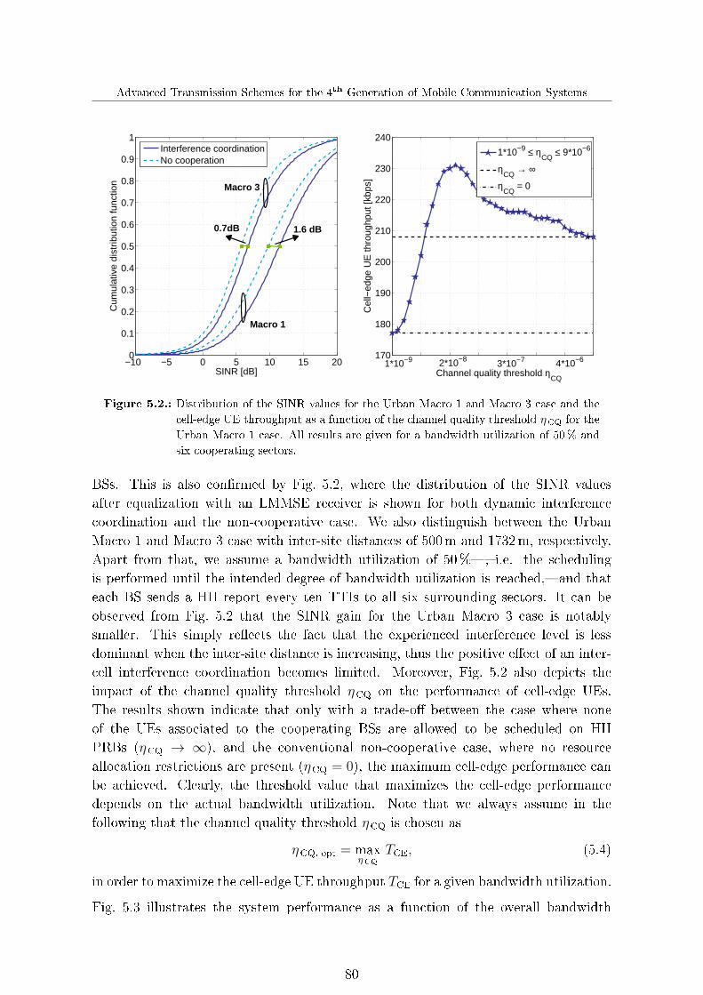
Advanced Transmission Schemes for the 4th Generation of Mobile Communication Systems
−10 −5 0 5 10 15 200
0.1
0.2
0.3
0.4
0.5
0.6
0.7
0.8
0.9
1
SINR [dB]
Cum
ulat
ive
dist
ribut
ion
func
tion
170
180
190
200
210
220
230
240
Cel
l−ed
ge U
E th
roug
hput
[kbp
s]
1*10−9 ≤ ηCQ
≤ 9*10−6
ηCQ
→ ∞
ηCQ
= 0
Interference coordinationNo cooperation
Macro 3
Macro 1
1.6 dB0.7dB
4*10−62*10−81*10−9 3*10−7
Channel quality threshold ηCQ
Figure 5.2.: Distribution of the SINR values for the Urban Macro 1 and Macro 3 case and the
cell-edge UE throughput as a function of the channel quality threshold ηCQ for the
Urban Macro 1 case. All results are given for a bandwidth utilization of 50% and
six cooperating sectors.
BSs. This is also con�rmed by Fig. 5.2, where the distribution of the SINR valuesafter equalization with an LMMSE receiver is shown for both dynamic interferencecoordination and the non-cooperative case. We also distinguish between the UrbanMacro 1 and Macro 3 case with inter-site distances of 500m and 1732m, respectively.Apart from that, we assume a bandwidth utilization of 50%�, i.e. the schedulingis performed until the intended degree of bandwidth utilization is reached,�and thateach BS sends a HII report every ten TTIs to all six surrounding sectors. It can beobserved from Fig. 5.2 that the SINR gain for the Urban Macro 3 case is notablysmaller. This simply re�ects the fact that the experienced interference level is lessdominant when the inter-site distance is increasing, thus the positive e�ect of an inter-cell interference coordination becomes limited. Moreover, Fig. 5.2 also depicts theimpact of the channel quality threshold ηCQ on the performance of cell-edge UEs.The results shown indicate that only with a trade-o� between the case where noneof the UEs associated to the cooperating BSs are allowed to be scheduled on HIIPRBs (ηCQ → ∞), and the conventional non-cooperative case, where no resourceallocation restrictions are present (ηCQ = 0), the maximum cell-edge performance canbe achieved. Clearly, the threshold value that maximizes the cell-edge performancedepends on the actual bandwidth utilization. Note that we always assume in thefollowing that the channel quality threshold ηCQ is chosen as
ηCQ, opt = maxηCQ
TCE, (5.4)
in order to maximize the cell-edge UE throughput TCE for a given bandwidth utilization.
Fig. 5.3 illustrates the system performance as a function of the overall bandwidth
80

Chapter 5. Advanced Transmission Techniques for the Uplink
10 20 40 60 80 1000
0.1
0.2
0.3
0.4
0.5
0.6
0.7
0.8
0.9
1
Bandwidth occupancy [%]
Ave
rage
spe
ctra
l effi
cien
cy [b
it/s/
Hz/
sect
or]
10 20 40 60 80 10050
100
150
200
250
300
350
400
Bandwidth occupancy [%]C
ell−
edge
UE
thro
ughp
ut [k
bps]
Interference coordination (ηCQ
= ηCQ,opt
)
Interference coordination (ηCQ
→ ∞)
No cooperation
Figure 5.3.: System performance of the dynamic interference coordination scheme as well as the
reference system without any cooperation as a function of the bandwidth occupancy
for the Urban Macro 1 case. For the interference coordination case, each BS sends
every ten TTIs a HII report to all six surrounding sectors.
10 20 30 40 50 60 70 80 90 1000
10
20
30
40
50
60
Bandwidth occupancy [%]
Rel
ativ
e ga
ins
com
pare
d to
bas
elin
e [%
]
Average spectral efficiencyCell−edge UE throughput
Urban Macro 1
Urban Macro 3
Figure 5.4.: Relative performance gains of the dynamic interference coordination scheme com-
pared to the reference system without cooperation for the Urban Macro 1 case and
six cooperating sectors. All results are given for ηCQ = ηCQ, opt and a HII report
interval of ten TTIs.
occupancy for the proposed dynamic interference coordination scheme as well as forthe non-cooperative case. First of all, it can be seen that signi�cant performance gainscan be achieved with dynamic interference coordination compared to a system without
81

Advanced Transmission Schemes for the 4th Generation of Mobile Communication Systems
cooperation. Interestingly, the gains increase with decreasing bandwidth occupancywhat is also con�rmed by Fig. 5.4, where the relative gains in terms of average spectrale�ciency as well as cell-edge throughput are illustrated. This indicates that the degreesof freedom in assigning PRBs to the various UEs is considerably increased at lowbandwidth utilizations. As a result, with a higher probability UEs located withina certain cooperating cluster are not simultaneously scheduled on the same PRBs,hence severe inter-cell interference situations are more often avoided. Apart from that,Fig. 5.3 also shows the results for the case ηCQ →∞, where no UEs are scheduled onPRBs indicated by the HII reports of cooperating BSs. Clearly, with this approach highinterference levels are completely avoided. However, it can be observed that the optimaltrade-o� with ηCQ = ηCQ, opt always outperforms the ηCQ → ∞ case. Basically, thisis because in the latter case the scheduling �exibility within the cooperation clusterbecomes limited, in particular for high bandwidth utilizations.
5.1.2. Cooperative interference-aware joint scheduling
Dynamic interference coordination, as considered in the previous section, is generallylimited by the imposed scheduling restrictions, which cannot be rapidly changed inan arbitrary manner due to the inherent BS to BS signaling delay over the backhaul.Due to the cell-speci�c resource allocation, the scheduling of one UE in a certain cellmay directly impose certain restrictions on other cooperating cells and vice versa.Thus, �nding the globally optimal solution becomes hardly feasible in practice for suchinterference coordination schemes. However, this drawback can be overcome with aglobal scheduling algorithm that is applied across all cooperating BSs, taking intoaccount the CSI of all associated UEs in order to �nd the optimal or at least close-to-optimal allocation of radio resources. In the following, we present such a centralizedcooperative interference-aware scheduling scheme, with which the resource allocationas well as the link adaptation is performed jointly by a central scheduling unit for aset of cooperating BSs [35,69].
5.1.2.1. Joint scheduling procedure
We consider the uplink of a cellular network as shown in Fig. 5.5, where di�erent BSsites are interconnected with a central scheduling unit via high-capacity backhaul links,hence facilitating a fast information exchange. It should be noted that the depictedcentral scheduling unit in Fig. 5.5 is not necessarily a separate device, but it may alsobe incorporated in one of the involved BSs. As illustrated in Fig. 5.5, all cooperatingBSs periodically send multi-cell CSI of the associated UEs to the corresponding centralscheduling unit, which thus becomes aware of the interference a certain UE scheduledin one cell would cause to another cell within the same cooperation cluster. In this way,high interference situations�which may occur, for example, if cell-edge UEs of neigh-boring cells are allocated to the same PRBs�can be avoided by taking the predicted
82
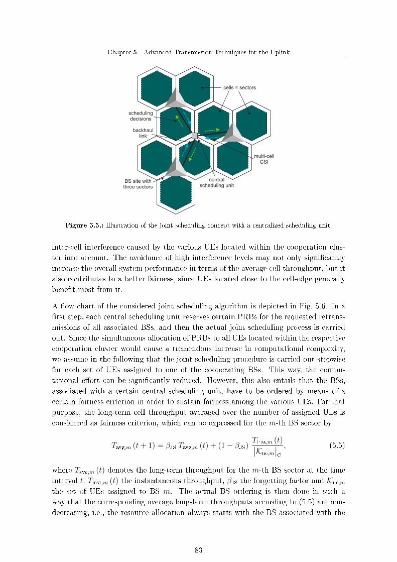
Chapter 5. Advanced Transmission Techniques for the Uplink
BS site withthree sectors
cells = sectors
schedulingdecisions
backhaullink
multi-cellCSI
centralscheduling unit
Figure 5.5.: Illustration of the joint scheduling concept with a centralized scheduling unit.
inter-cell interference caused by the various UEs located within the cooperation clus-ter into account. The avoidance of high interference levels may not only signi�cantlyincrease the overall system performance in terms of the average cell throughput, but italso contributes to a better fairness, since UEs located close to the cell-edge generallybene�t most from it.
A �ow chart of the considered joint scheduling algorithm is depicted in Fig. 5.6. In a�rst step, each central scheduling unit reserves certain PRBs for the requested retrans-missions of all associated BSs, and then the actual joint scheduling process is carriedout. Since the simultaneous allocation of PRBs to all UEs located within the respectivecooperation cluster would cause a tremendous increase in computational complexity,we assume in the following that the joint scheduling procedure is carried out stepwisefor each set of UEs assigned to one of the cooperating BSs. This way, the compu-tational e�ort can be signi�cantly reduced. However, this also entails that the BSs,associated with a certain central scheduling unit, have to be ordered by means of acertain fairness criterion in order to sustain fairness among the various UEs. For thatpurpose, the long-term cell throughput averaged over the number of assigned UEs isconsidered as fairness criterion, which can be expressed for the m-th BS sector by
Tavg,m (t+ 1) = βJS Tavg,m (t) + (1− βJS)Tinst,m (t)∣∣Kue,m
∣∣C
, (5.5)
where Tavg,m (t) denotes the long-term throughput for the m-th BS sector at the timeinterval t, Tinst,m (t) the instantaneous throughput, βJS the forgetting factor and Kue,m
the set of UEs assigned to BS m. The actual BS ordering is then done in such away that the corresponding average long-term throughputs according to (5.5) are non-decreasing, i.e., the resource allocation always starts with the BS associated with the
83

Advanced Transmission Schemes for the 4th Generation of Mobile Communication Systems
HARQ management
Ordering of thecooperating BSs
Resourceallocation performed for
all cooperating BSs?yes
no
Determine jointscheduling priorities for
current BS
Perform resourceallocation
Link adaptation basedon exchanged multi-cell
CSI
Interference-aware jointscheduling completed
Figure 5.6.: Flow chart of the interference-aware joint scheduling algorithm.
lowest long-term throughput, then it is done for the one with the second smallest one,etc.
Having determined the ordering of the cooperating BSs, the PRBs are allocated to thevarious UEs based on the exchanged multi-cell CSI. To this end, not only the currentchannel conditions between the UEs and their serving BSs are taken into account,but also the expected inter-cell interference caused by assigning these UEs to certainPRBs. Thus, the joint scheduling priority for the b-th PRB and i-th UE associated toits serving BS m can be expressed by
Si,b (t) = Gi,b,Kb (t) +∑n∈Kb
Gn,b,Kb (t) , i ∈ Kue,m, (5.6)
where Gi,b,Kb (t) denotes the scheduling priority for the i-th UE allocated to the b-thPRB on which the set of UEs Kb is already scheduled. Furthermore, Gn,b,Kb (t) indicatesthe updated scheduling priority for the already scheduled UE n, taking into accountthe fact that the i-th UE will be allocated to the b-th PRB. In this regard, the updatedset of interfering UEs allocated to the b-th PRB for the n-th UE is given by
Kb =(Kb\n
)∪ i. (5.7)
In the following, only the calculation of the scheduling priority Gn,b,Kb (t) is explicitlyoutlined, but the scheduling priority Gi,b,Kb (t) can be determined in a similar way andtherefore is not further considered in more detail here. It is assumed that the PRBs areshared between the various UEs by means of the well-known proportional fair approach(cf. Section 3.2), but it should be noted that any other scheduling metric may be used
84

Chapter 5. Advanced Transmission Techniques for the Uplink
in conjunction with our joint scheduling scheme as well. According to (3.3), Gn,b,Kb (t)
can be determined by
Gn,b,Kb (t) =Rn,b,Kb (t)
TαPFn (t), (5.8)
where the instantaneous supportable throughput Rn,b,Kb (t) may be estimated by meansof the Shannon capacity formula
Rn,b,Kb (t) =
Ksub∑k=1
log2(
1 + γn,b,Kb,k
), (5.9)
with Ksub as the number of subcarrier per PRB, γn,b,Kb,k as the uplink SINR of the n-thUE on the b-th radio resource. Let us in the following assume that all BSs are equippedwith Nbs receive antenna elements, whereas all UEs have only a single antenna element.Then, the uplink SINR γn,b,Kb,k can be expressed by
γn,b,Kb,k =Pn,b,k E
[∣∣sn,b,k∣∣2] wn,b,k hn,b,k hHn,b,kw
Hn,b,k
wn,b,k E[in,b,Kb,k i
Hn,b,Kb,k
]+ E
[nnH
]wHn,b,k
, (5.10)
with Pn,b,k as the transmitting power of the n-th UE for the k-th subcarrier of PRB b,sn,b,k as the transmitted symbol of the n-th UE, hn,b,k ∈ C[Nbs×1] as the channel vectorfrom the n-th UE to its serving BS, wn,b,k ∈ C[1×Nbs] as the corresponding weight vectorfor coherent detection, in,b,Kb,k ∈ C[Nbs×1] as the inter-cell interference caused by the setof UEs Kb and n ∈ C[Nbs×1] as the thermal noise.
Based on the exchanged multi-cell CSI, the central scheduling unit is able to predict the
interference covariance matrix Rii = E[in,b,Kb,k i
Hn,b,Kb,k
]∈ C[Nbs×Nbs] in (5.10), which is
given by
Rii =∑j ∈ Kb
Pj,b,k E[∣∣sj,b,k∣∣2] hj,n,b,k hHj,n,b,k, (5.11)
where Pj,b,k denotes the transmitting power of UE j for the k-th subcarrier of PRBb, sj,b,k the transmitted symbol of the j-th UE, and hj,n,b,k ∈ C[Nbs×1] the channelvector from the j-th UE to the serving BS of UE n. Clearly, Rii in (5.10) containsboth the inter-cell interference level caused by the already scheduled UEs associatedto the cooperating BSs as well as the one that will be generated by assigning the i-thUE to the considered PRB. As a result, the joint scheduling priorities in (5.6) re�ectthe weighted sum throughput, under consideration of the current inter-cell interferencesituation. This consequently leads to an interference-aware joint scheduling, aimingat reducing the inter-cell interference within the given cooperation cluster, while stilltaking channel-dependent scheduling as well as user fairness into account.
Finally, after completing the resource allocation of all cooperating BSs, the link adap-tation selects for each UE the spectrally most e�cient MCS that can be supported byits current uplink channel without exceeding a given target BLER. To this end, the
85

Advanced Transmission Schemes for the 4th Generation of Mobile Communication Systems
corresponding SINR is estimated by evaluating the available multi-cell CSI, resultingin a more accurate link adaptation. This is because the knowledge of which UEs arescheduled in the cooperating cells together with the available multi-cell CSI facilitatean accurate prediction of the interference situation that will occur during the actual(future) data transmission. Note that, especially in the uplink, this may lead to sig-ni�cant additional performance gains, since the interference situation there is usuallyrather volatile. This is due to the fact that from one TTI to the other, completelydi�erent sets of UEs may be scheduled in nearby cells.
5.1.2.2. Practical considerations
A crucial prerequisite for proper operation of the proposed interference-aware jointscheduling approach in practice is that a BS is able to perform accurate multi-cellchannel estimation. For that purpose, it is necessary that the reference signals trans-mitted by di�erent UEs within a certain cooperation cluster can be separated againat the BS side, for example through orthogonal reference signals. In any case, all BSshave to be aware of the reference signals assigned to the various UEs. This conse-quently requires further signaling between cooperating BSs in addition to the actualmulti-cell CSI and the resource allocation tables via the backhaul network, as alreadyoutlined before. However, note that this usually does not have to be done during everyTTI, since the utilized reference signals and hopping patterns are normally assignedin a semi-persistent manner. Therefore, this additional backhaul load is expected tobe comparatively small. Note that the requirements on the accuracy of the multi-cellchannel estimation are rather stringent in the case of interference-aware joint schedul-ing. This is due to the fact that the resource allocation decisions depend heavily onthe predicted inter-cell interference level caused by single UEs, which means that ahigh deviation between the predicted and the actual interference levels during a datatransmission would lead to inaccurate resource allocation decisions.
Another prerequisite for the proposed approach is that cooperating BSs can quicklyexchange information with the central scheduling unit via a fast backhaul network.However, it is quite clear that even if the backhaul network consists of direct optical�ber links, in general an additional delay is introduced because some time is alwaysrequired for the processing of the exchanged information and the actual schedulingprocess. As a consequence, the overall latency increases and the performance maydegrade to some extent compared to the idealized case without any additional delay.This is because of an increased mismatch between the channels used as the basis forthe scheduling and link adaptation stages and those during the actual data transmis-sion. Besides, the increased delay between scheduling and actual data transmissionclearly also a�ects potential HARQ retransmissions. In the LTE uplink, currently asynchronous HARQ protocol is used. If the proposed joint scheduling scheme is to beintroduced in LTE-A, it might therefore be necessary to adjust the HARQ timing.
86

Chapter 5. Advanced Transmission Techniques for the Uplink
5.1.2.3. System performance of joint scheduling
Fig. 5.7 illustrates the system performance that can be achieved with the proposedinterference-aware joint scheduling scheme, where all BS sites are interconnected withone single central scheduling unit, which is always assumed in the following. Thus, theresource allocation is jointly performed across all BS sites of the considered deploymentscenario. However, each BS sector has only multi-cell CSI of the UEs associated withits six surrounding cooperating sectors; thus, only the inter-cell interference caused bythese UEs can be taken into account for the resource allocation. Apart from that, if notstated otherwise, we assume that the BSs report every two TTIs their multi-cell CSIto the central scheduling unit. Moreover, an additional delay of two TTIs introducedby signaling the scheduling decisions from the central scheduling unit to the corre-sponding BS is considered. It can be seen from Fig. 5.7 that the system performanceand in particular the cell-edge throughput is signi�cantly increased with the proposedinterference-aware joint scheduling scheme compared to a conventional system withoutany cooperation. Since cell-edge UEs su�er most from inter-cell interference, they arethe ones bene�ting the most from the joint resource allocation. Additionally, Fig. 5.7also shows the upper limits of the system performance if the exchange of the multi-cellCSI from the BSs to the central scheduling unit can be realized without any additionaldelay. Hence, the performance is not degraded due to a mismatch between the channelsperiodically determined during the multi-cell channel estimation stage at the BS sitesand the ones used as the basis for the resource allocation at the central scheduling unit.
Moreover, for comparison Fig. 5.7 also depicts the system performance of the state-of-the-art dynamic interference coordination scheme presented in the previous section.First of all, it can be seen that our interference-aware joint scheduling scheme outper-forms dynamic interference coordination due to the higher �exibility in jointly allocat-ing PRBs to the various UEs, which consequently leads to an improved avoidance ofsevere inter-cell interference. The better system performance in the case of interference-aware joint scheduling, however, comes at the cost of an increased backhaul load dueto the required exchange of the multi-cell CSI1.
Fig. 5.8 illustrates the impact of the number of cooperating sectors on the system per-formance. As can be seen, the system performance steadily improves with an increasingnumber of cooperating sectors for both the Urban Macro 1 and the Macro 3 case. Thisis because the resource allocation of the various UEs becomes more accurate due to thelarger amount of multi-cell CSI, as does the link adaptation. Since the link adaptationselects the appropriate MCSs based on the periodically exchanged multi-cell CSI, theprediction of the current interference levels can be considerably improved with the in-creasing number of cooperating sectors, thus leading to a reduced probability of over-
1The average backhaul load per BS for the dynamic interference coordination scheme is about 25 kbps,
assuming six cooperating sectors. By contrast, the backhaul requirement of the interference-aware
joint scheduling scheme is about 192Mbps (cf. Fig. 5.9).
87

Advanced Transmission Schemes for the 4th Generation of Mobile Communication Systems
30% 60% 100%0
0.2
0.4
0.6
0.8
1
1.2
1.4
Bandwidth occupancy [%]
Avera
ge s
pectr
al effic
iency [bit/s
/Hz/s
ecto
r]
30% 60% 100%0
100
200
300
400
500
600
700
Bandwidth occupancy [%]C
ell-
edge U
E thro
ughput [k
bps]
Interference coordination
Joint scheduling w/ delayed CSI
Joint scheduling w/o delayed CSI
No cooperation
+3%
+42%
+27%+30%
+92%+99%
+14%
+44%+39% +52%
+15%
+40%
+95%+113%
+23%
+61%
+77%
+69%
Figure 5.7.: System performance comparison between dynamic interference coordination and
interference-aware joint scheduling for di�erent bandwidth utilizations, assuming
six cooperating sectors for both cases. The given percentages denote the relative
performance gains compared to our LTE-based reference system without coopera-
tion.
Urban Macro 1 Urban Macro 3
0
0.2
0.4
0.6
0.8
1
1.2
Avera
ge s
pectr
al effic
iency [bit/s
/Hz/s
ecto
r]
Urban Macro 1 Urban Macro 3
0
100
200
300
400
500
600
700
Cell-
edge U
E thro
ughput [k
bps]
(1) 6 cooperating sectors
(2) 20 cooperation sectors
(3) Global cooperation
No cooperation
+41%+38%
+27%
+75%+70%
+52%
+19%+18%+16%
+40%+43%+44%
(1) (2) (3) (1) (2) (3)(1) (2) (3) (1) (2) (3)
Figure 5.8.: Impact of the number cooperating sectors on the system performance for the Urban
Macro 1 and Macro 3 case. The given percentages denote the relative performance
gains compared to the baseline system without cooperation.
or underestimating the instantaneous MCS. It can also be seen from Fig. 5.8 that withsix cooperating sectors most of the potential performance gains that are theoreticallypossible with the proposed interference-aware joint scheduling scheme can already berealized. This is due to the fact that the interference coming from BSs located at aconsiderable distance has no signi�cant e�ect on the performance: thus is especiallytrue for the Urban Macro 3 case with an inter-site distance of 1732m.
88
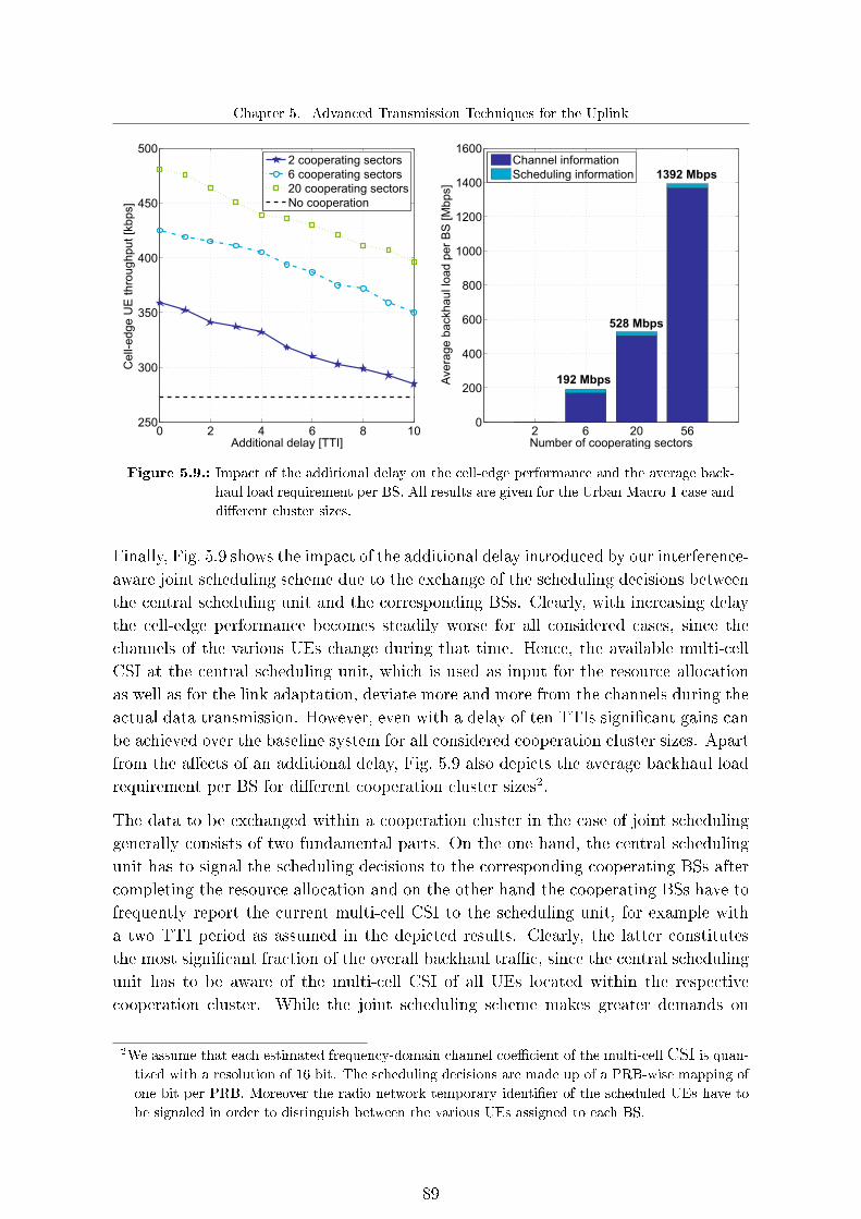
Chapter 5. Advanced Transmission Techniques for the Uplink
0 2 4 6 8 10250
300
350
400
450
500
Additional delay [TTI]
Cell-
edge U
E thro
ughput [k
bps]
2 cooperating sectors
6 cooperating sectors
20 cooperating sectors
No cooperation
2 6 20 560
200
400
600
800
1000
1200
1400
1600
Number of cooperating sectorsA
vera
ge b
ackhaul lo
ad p
er
BS
[M
bps]
Channel information
Scheduling information
192 Mbps
528 Mbps
1392 Mbps
Figure 5.9.: Impact of the additional delay on the cell-edge performance and the average back-
haul load requirement per BS. All results are given for the Urban Macro 1 case and
di�erent cluster sizes.
Finally, Fig. 5.9 shows the impact of the additional delay introduced by our interference-aware joint scheduling scheme due to the exchange of the scheduling decisions betweenthe central scheduling unit and the corresponding BSs. Clearly, with increasing delaythe cell-edge performance becomes steadily worse for all considered cases, since thechannels of the various UEs change during that time. Hence, the available multi-cellCSI at the central scheduling unit, which is used as input for the resource allocationas well as for the link adaptation, deviate more and more from the channels during theactual data transmission. However, even with a delay of ten TTIs signi�cant gains canbe achieved over the baseline system for all considered cooperation cluster sizes. Apartfrom the a�ects of an additional delay, Fig. 5.9 also depicts the average backhaul loadrequirement per BS for di�erent cooperation cluster sizes2.
The data to be exchanged within a cooperation cluster in the case of joint schedulinggenerally consists of two fundamental parts. On the one hand, the central schedulingunit has to signal the scheduling decisions to the corresponding cooperating BSs aftercompleting the resource allocation and on the other hand the cooperating BSs have tofrequently report the current multi-cell CSI to the scheduling unit, for example witha two TTI period as assumed in the depicted results. Clearly, the latter constitutesthe most signi�cant fraction of the overall backhaul tra�c, since the central schedulingunit has to be aware of the multi-cell CSI of all UEs located within the respectivecooperation cluster. While the joint scheduling scheme makes greater demands on
2We assume that each estimated frequency-domain channel coe�cient of the multi-cell CSI is quan-tized with a resolution of 16 bit. The scheduling decisions are made up of a PRB-wise mapping of
one bit per PRB. Moreover the radio network temporary identi�er of the scheduled UEs have to
be signaled in order to distinguish between the various UEs assigned to each BS.
89

Advanced Transmission Schemes for the 4th Generation of Mobile Communication Systems
the backhaul requirement than the dynamic interference coordination scheme, it stillrequires only a moderate backhaul load compared to full complexity joint receptionschemes, as will be shown in Section 5.3. Thus, the interference-aware joint schedulingscheme represents a very attractive option for future mobile communication systems.
5.2. Cooperative interference prediction
A general problem of any fast link adaptation scheme in wireless mobile communicationsystems is that there is always an inherent delay between the time when the link adap-tation is performed and the actual data transmission. As a consequence, the selectedtransmission parameters are often not optimal anymore when the data transmissionactually takes places. On the one hand, this is because the involved channels naturallychange during that time, but at least for low to moderate user speeds, the impact ofthis e�ect should be only minor. On the other hand and more importantly, however,the interference situation during the data transmission might be completely di�erentfrom the interference situation during the time when the link adaptation has beenperformed. This unstable behavior of the interference generally has a negative impacton the performance of fast link adaptation schemes. Therefore, the selected MCSs arefrequently over or underestimated, thus leading to a very high BLER or a rather lowspectral e�ciency, respectively. This particularly holds for the cellular uplink, sincefrom one TTI to the next completely di�erent sets of UEs might be scheduled in nearbycells, thus causing completely di�erent levels of interference.
A standard approach to countervail this e�ect is to employ as an addition to the conven-tional link adaptation scheme an outer loop mechanism, which dynamically readjuststhe target BLER based on the actually measured BLER, such that the desired oper-ating point can be achieved at least on average (cf. [76] and Section 2.3.2). However,even with such an outer loop scheme, the performance is generally still signi�cantlyworse than with (theoretical) optimal link adaptation, since the instantaneously se-lected MCSs often might still deviate considerably from the ones that actually wouldbe optimal at that time. Therefore, we propose in this section a novel approach forcooperation-based interference prediction through which the link adaptation can besigni�cantly improved [69,73]. The basic idea is to predict in advance the interferencelevel that a BS will experience during a future data transmission, so that the linkadaptation process can be considerably improved. This is accomplished by exchangingscheduling information between a set of cooperating BSs via a fast backhaul networkcombined with multi-cell channel estimation.
5.2.1. Enhanced link adaptation
The fundamental idea of the interference prediction scheme under consideration is toperform the link adaptation based not upon the currently estimated SINR values, but
90
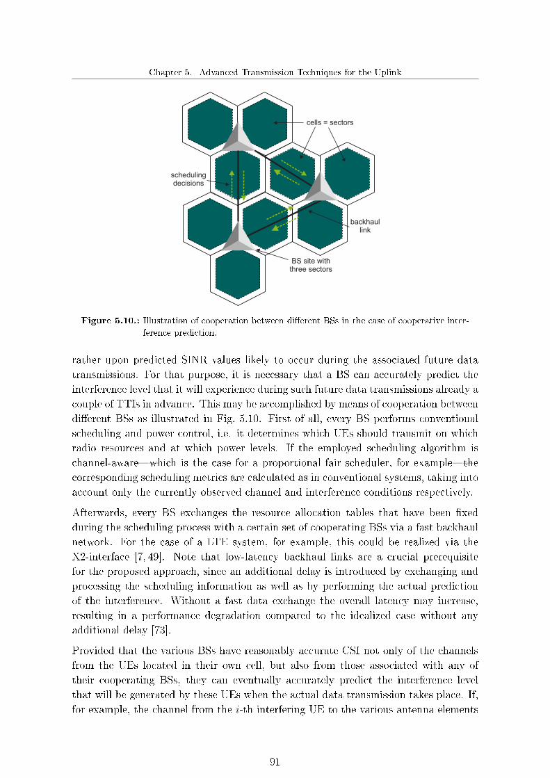
Chapter 5. Advanced Transmission Techniques for the Uplink
BS site withthree sectors
cells = sectors
schedulingdecisions
backhaullink
Figure 5.10.: Illustration of cooperation between di�erent BSs in the case of cooperative inter-
ference prediction.
rather upon predicted SINR values likely to occur during the associated future datatransmissions. For that purpose, it is necessary that a BS can accurately predict theinterference level that it will experience during such future data transmissions already acouple of TTIs in advance. This may be accomplished by means of cooperation betweendi�erent BSs as illustrated in Fig. 5.10. First of all, every BS performs conventionalscheduling and power control, i.e. it determines which UEs should transmit on whichradio resources and at which power levels. If the employed scheduling algorithm ischannel-aware�which is the case for a proportional fair scheduler, for example�thecorresponding scheduling metrics are calculated as in conventional systems, taking intoaccount only the currently observed channel and interference conditions respectively.
Afterwards, every BS exchanges the resource allocation tables that have been �xedduring the scheduling process with a certain set of cooperating BSs via a fast backhaulnetwork. For the case of a LTE system, for example, this could be realized via theX2-interface [7, 49]. Note that low-latency backhaul links are a crucial prerequisitefor the proposed approach, since an additional delay is introduced by exchanging andprocessing the scheduling information as well as by performing the actual predictionof the interference. Without a fast data exchange the overall latency may increase,resulting in a performance degradation compared to the idealized case without anyadditional delay [73].
Provided that the various BSs have reasonably accurate CSI not only of the channelsfrom the UEs located in their own cell, but also from those associated with any oftheir cooperating BSs, they can eventually accurately predict the interference levelthat will be generated by these UEs when the actual data transmission takes place. If,for example, the channel from the i-th interfering UE to the various antenna elements
91

Advanced Transmission Schemes for the 4th Generation of Mobile Communication Systems
of a particular BS sector is denoted by hi ∈ C[Nbs×1], then the expected contribution ofthis interferer to the overall interference covariance matrix simply would be given by
Rii = Pi E[|si|2
]hi h
Hi , (5.12)
where Pi and si are the transmitting power and the transmitted symbol associatedwith the i-th UE, respectively. The predicted interference is then used as an input tothe link adaptation stage. Afterwards, the corresponding scheduling grants (includingthe assigned MCSs) are signaled to all scheduled UEs, which �nally transmit theirdata a couple of TTIs after the reception of these grants. However, note that thescheduling decisions themselves are not updated based on the predicted interferencelevels, since otherwise the actual future interference situation would change again.Hence, in that case some iterative procedure would be necessary, thus leading to anincreased complexity and backhaul load as well as a higher latency.
Clearly, the performance of the approach strongly depends on the number of coop-erating BSs. While a BS generally should be able to predict the interference fairlyaccurately with a large number of cooperation partners, it would frequently underesti-mate the actual interference level if it cooperates only with very few other BSs. This isbecause with the basic scheme as described above no interference from non-cooperatingcells is taken into account. In real-world scenarios, however, the set of cooperating BSsis in most cases very likely to be restricted to nearby neighbors only, on the one hand inorder to keep the backhaul load limited and on the other hand because it is unrealisticthat a BS may accurately estimate the channels from all UEs within a large number ofcooperating cells. Therefore, it is essential that the impact of the interference causedby UEs in non-cooperating cells is somehow taken into account as well. An e�cient wayto do that is to employ an additional outer loop link adaptation scheme, as presentedin Section 2.3.2. One of the main tasks of the outer loop link adaptation scheme is toadjust the SINR o�set such that it accounts for the average interference level generatedby UEs in non-cooperating cells.
5.2.2. Practical considerations
In general, the same practical considerations have to be taken into account for theproposed interference prediction scheme as for the interference-aware joint schedulingscheme (cf. Section 5.1.2.2). However, the requirements on the accuracy of the multi-cell channel estimation between a BS and UEs located in other cells are generallymuch lower than those for the estimation of the desired link between a certain UEand its serving BS in the case of interference prediction. On the one hand, this isbecause estimation errors made for di�erent interfering channels may compensate eachother�particularly if the number of cooperating BSs is relatively high�and on theother hand because it may be already su�cient for achieving a good performance toknow whether on a certain radio resource very high or very low interference has to
92

Chapter 5. Advanced Transmission Techniques for the Uplink
be expected, whereas the exact �gures are only of secondary importance. In addition,if the channel from a certain UE in one of the cooperating cells cannot be estimatedreliably, because it is in a deep fade, this should also not represent a major problem,since in such a case this UE would cause only low interference anyway.
5.2.3. System performance of interference prediction
Fig. 5.11 shows the performance that can be achieved with the proposed interferenceprediction scheme for di�erent bandwidth utilizations. In order to achieve a certainbandwidth occupancy, the scheduling is performed until the intended degree of band-width utilization is reached. Both the average spectral e�ciency as well as the cell-edgethroughput�which we de�ne as the 5th percentile point of the cumulative distributionfunction of the UE throughput�are depicted, and we consider di�erent numbers ofcooperating BSs as well as the idealized case with perfect link adaptation, where theMCS is selected in retrospect based on the channel conditions during the actual datatransmission. If not stated otherwise, we always assume in the following the UrbanMacro 1 case with an inter-site distance of 500m, proportional fair scheduling, as wellas two receive antenna elements per BS sector and a single transmit antenna at eachUE. We consider an additional delay of two TTIs due to information exchange, pro-cessing and actual prediction of the interference. The case with six cooperating sectorsactually corresponds to the situation in which each BS receives resource allocation ta-bles from all surrounding sectors, whereas in the case of 20 cooperating sectors, eachBS receives resource allocation tables from all sectors of all six surrounding sites, aswell as the other two sectors of the same site.
It can be seen from Fig. 5.11 that signi�cant performance gains up to 47% and 65%in terms of average spectral e�ciency and cell-edge throughput may be obtained, con-sidering six cooperating sectors and a bandwidth utilization of 30%. In this regard,we note the relative gains are always higher in terms of the cell-edge throughput thanin terms of the average spectral e�ciency. This is because UEs with a rather poorchannel on average generally are scheduled on only very few PRBs, since they oftenbecome power-limited. Hence, without interference prediction, variations of the inter-ference level on these PRBs between the time when the link adaptation is performedand the actual data transmission often have a higher impact on the performance thanfor cell-center UEs, which are usually scheduled on more PRBs. The more PRBs areassigned to a UE, the higher the probability gets that changing interference conditionson some PRBs might be compensated by conversely changing interference conditionson other PRBs. In other words, if on some PRBs the interference level estimated duringthe link adaptation is higher than the one observed during the data transmission, thisimpact is partially compensated if on other PRBs it is exactly the other way around.Clearly, the more PRBs are assigned to a certain UE, the more probable it becomesthat such a compensation occurs. Hence, cell-edge UEs generally su�er more from
93

Advanced Transmission Schemes for the 4th Generation of Mobile Communication Systems
30% 100%0
0.2
0.4
0.6
0.8
1
1.2
Bandwidth occupancy [%]
Avera
ge s
pectr
al effic
iency [bit/s
/Hz/s
ecto
r]
30% 100%0
100
200
300
400
500
600
Bandwidth occupancy [%]C
ell-
edge U
E thro
ughput [k
bps]
6 cooperating sectors
20 cooperating sectors
Global cooperation
Ideal link adaptation
No cooperation
+47%+51%+52%
+58%
+22%
+33%+36%
+42%
+65%
+29%
+72%
+41%
+76%
+50%
+81%
+59%
Figure 5.11.: System performance with interference prediction and various numbers of cooper-
ating sectors as well as (idealized) perfect link adaptation for di�erent bandwidth
utilizations, assuming an additional delay of two TTIs. The given percentages
denote the relative performance gains compared to the baseline system without
cooperation.
the volatile nature of the interference and therefore they also bene�t more from theproposed interference prediction scheme.
Interestingly, it can be seen from Fig. 5.11 that the achievable performance is heavilydependent on the bandwidth occupancy. The gains increase with decreasing bandwidthoccupancy, a factor that indicates that the interference situation for a low bandwidthutilization is even more volatile, since the probability that on some PRBs no UEs arescheduled by the neighboring BSs is signi�cantly increased. However, this leads tohigher �uctuations in the interference level, so that selected MCSs are more frequentlyover- or underestimated without any interference prediction for low bandwidth utiliza-tions. As a result, the bene�ts of accurately predicting the interference situation withour proposed scheme are even higher for lower bandwidth utilizations. Moreover, weobserve from Fig. 5.11 that with six cooperating sectors already most of the potentialperformance gains that are theoretically possible with interference prediction can berealized. This simply re�ects the fact that the biggest share of the interference gen-erally comes from the surrounding sectors, what is particularly true for cases with arelatively large inter-site distance. Finally, it should be noted that the performancewith global cooperation in Fig. 5.11 is still worse compared to the case with ideal linkadaptation, since even with global cooperation, we still have a certain delay betweenthe link adaptation stage and the actual data transmission.
An example for how the accuracy of the link adaptation can be improved with theproposed approach is depicted in Fig. 5.12, where the distribution for certain devia-tions between the ideal and the used MCSs are shown for the cases with and without
94

Chapter 5. Advanced Transmission Techniques for the Uplink
−10 −8 −6 −4 −2 0 2 4 6 8 100
5
10
15
20
25
Deviation between selected and ideal MCS [MCS indices]
Pro
babi
lity
[%]
−10 −8 −6 −4 −2 0 2 4 6 8 100
5
10
15
20
25
Deviation between selected and ideal MCS [MCS indices]
Pro
babi
lity
[%]
Selected MCS deviates from ideal MCSSelected MCS corresponds to ideal MCS
without interference prediction
with interference prediction
Figure 5.12.: Accuracy of the link adaptation process without and with interference prediction
for the Urban Macro 1 scenario with an inter-site distance of 500m. In the case
of interference prediction, each BS always receives scheduling information with
two TTIs delay from all 6 surrounding sectors. The used MCSs are given in
Appendix A.
interference prediction. In this regard, the BSs may choose between several di�erentMCSs, as outlined in Section 2.3.2. It can be seen that with interference predictionthe probability that the ideal MCS is selected is almost twice as high as for the casewithout interference prediction and also the variance of the deviations from the idealMCS can be considerably reduced.
Finally, Fig. 5.13 depicts on the one hand the impact of the additional delay introducedby our approach, considering three di�erent cases with two, six, and 20 cooperatingsectors, respectively. In the �rst case we actually have intra-site cooperation, sincescheduling decisions are only exchanged between the sectors belonging to the samesite. As can be seen, with increasing delay the cell-edge performance becomes steadilyworse, a situation which can be attributed to the fact that the channels of the variousUEs change during that time. Hence, the channels used as the basis for the schedulingand link adaptation stages deviate more and more from the channels during the actualdata transmission. For the case with two cooperating sectors, the performance actuallymight become even worse than without interference prediction if the delay exceedssix TTIs, but since no backhaul signaling is required in that case, the actual delayin practice usually should be much smaller. With six or 20 cooperating sectors, incontrast, even with ten TTIs delay moderate performance gains can still be realized.In presence of optical �ber links between cooperating BSs, the actual delay mightbe also in this case much smaller, thus still leading to considerable improvements.Moreover, Fig. 5.13 also illustrates the required backhaul capacity, where we measurethe required backhaul load as the maximum of the occurring input and output tra�c at
95
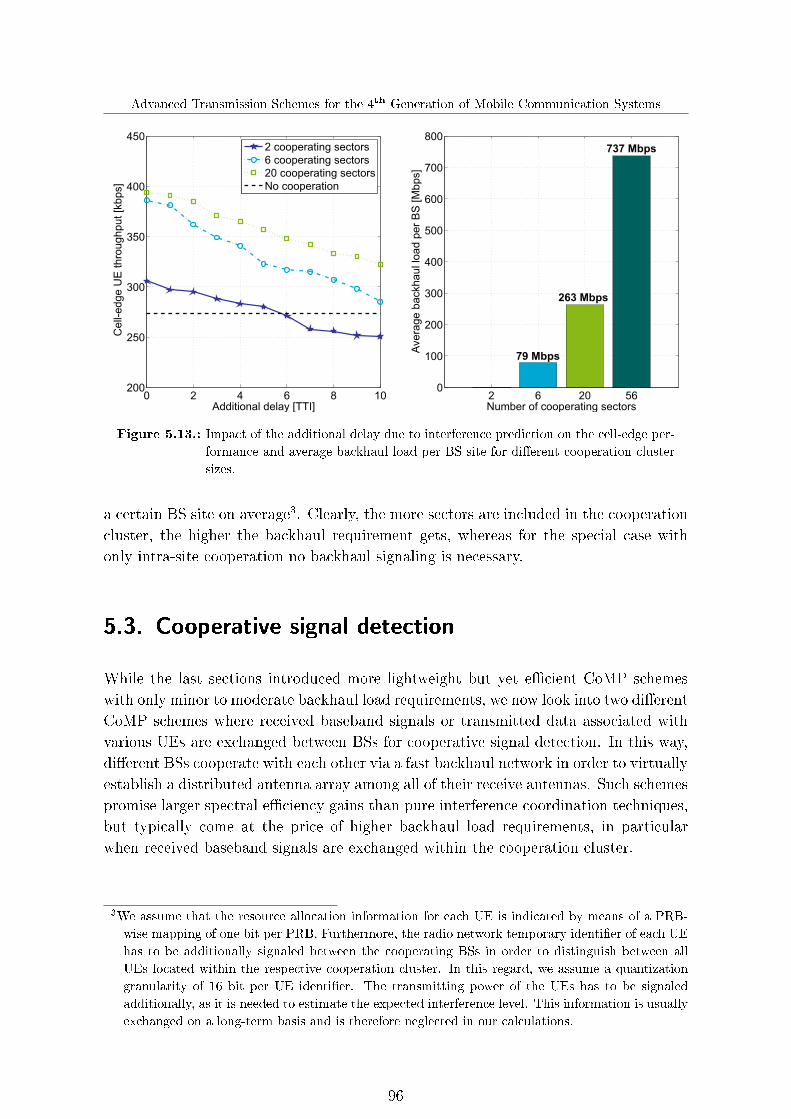
Advanced Transmission Schemes for the 4th Generation of Mobile Communication Systems
0 2 4 6 8 10200
250
300
350
400
450
Additional delay [TTI]
Cell-
edge U
E thro
ughput [k
bps]
2 cooperating sectors
6 cooperating sectors
20 cooperating sectors
No cooperation
2 6 20 560
100
200
300
400
500
600
700
800
Number of cooperating sectorsA
vera
ge b
ackhaul lo
ad p
er
BS
[M
bps]
263 Mbps
79 Mbps
737 Mbps
Figure 5.13.: Impact of the additional delay due to interference prediction on the cell-edge per-
formance and average backhaul load per BS site for di�erent cooperation cluster
sizes.
a certain BS site on average3. Clearly, the more sectors are included in the cooperationcluster, the higher the backhaul requirement gets, whereas for the special case withonly intra-site cooperation no backhaul signaling is necessary.
5.3. Cooperative signal detection
While the last sections introduced more lightweight but yet e�cient CoMP schemeswith only minor to moderate backhaul load requirements, we now look into two di�erentCoMP schemes where received baseband signals or transmitted data associated withvarious UEs are exchanged between BSs for cooperative signal detection. In this way,di�erent BSs cooperate with each other via a fast backhaul network in order to virtuallyestablish a distributed antenna array among all of their receive antennas. Such schemespromise larger spectral e�ciency gains than pure interference coordination techniques,but typically come at the price of higher backhaul load requirements, in particularwhen received baseband signals are exchanged within the cooperation cluster.
3We assume that the resource allocation information for each UE is indicated by means of a PRB-
wise mapping of one bit per PRB. Furthermore, the radio network temporary identi�er of each UE
has to be additionally signaled between the cooperating BSs in order to distinguish between all
UEs located within the respective cooperation cluster. In this regard, we assume a quantization
granularity of 16 bit per UE identi�er. The transmitting power of the UEs has to be signaled
additionally, as it is needed to estimate the expected interference level. This information is usually
exchanged on a long-term basis and is therefore neglected in our calculations.
96

Chapter 5. Advanced Transmission Techniques for the Uplink
We propose a promising CoMP scheme called joint detection, where not merely thesignal received by a single BS is evaluated, but rather where the signals received by mul-tiple cooperating BSs are jointly processed in an appropriate way [37, 74]. In general,one can distinguish between intra-site joint detection where, additionally, di�erent sec-tors of the same BS site jointly detect the received signal, and inter-site joint detection,where also sectors belonging to di�erent sites may be incorporated in the cooperationcluster. However, in the latter case, data has to be exchanged between the involvedBSs via a fast backhaul network. Thus, the application of inter-site joint detection ismore complex than intra-site joint detection due to several practical constraints, suchas the additional delay due to the information exchange between the cooperating BSsand the joint processing, the synchronization of the UEs to all cooperating BSs, andthe adjustment of the timing advance.
One of the main challenges for realizing inter-site cooperation in practical systems,however, is the tremendous amount of data to be exchanged between the cooperatingsectors of di�erent BS sites. As a consequence, from an operators' point of view intra-site joint detection seems to be an attractive option as an intermediate step towardsgeneral inter-site joint detection, since the intra-site approach does not su�er from anyrestrictions due to limitations of the underlying backhaul network. Basically, there areno limitations concerning the amount of data that might be exchanged: furthermore,the additional delay due to the cooperation stage becomes almost negligible. Besides,since all sectors belonging to the same site might be driven by the same clock, thesynchronization of a certain UE to all cooperating sectors can be readily achieved:particularly in the uplink, there is no major problem with respect to the proper ad-justment of the timing advance. Finally, this approach might be already realized withstate-of-the art systems, such as LTE Release 8, as no backhaul signaling is involvedand hence no further standardization would be required for that purpose.
In order to reduce the tremendous backhaul load requirements of inter-site joint detec-tion, we propose a novel distributed multi-cell successive interference cancelation (SIC)scheme. In contrast to the inter-site joint detection approach, only intra-site joint de-tection is performed and instead of exchanging received baseband signals only thetransmitted data of already detected UEs is signaled over the backhaul in order tocancel the inter-cell interference caused by these UEs. Provided that each BS is ableto perform accurate multi-cell channel estimation, the inter-cell interference caused bythe already detected UEs can be reconstructed and then subtracted from the receivedsignals, thus improving the SINR.
Note that the study of the theoretical limits of cooperative signal detection strategieshas attracted a lot of research attention during the past few years (see for example[68, 85, 103]), but a realistic analysis of the gains that may be achieved with suchtechniques represents still a largely untouched yet important research area [37,50,69].
97

Advanced Transmission Schemes for the 4th Generation of Mobile Communication Systems
5.3.1. Joint detection
We consider the uplink of a cellular network as depicted in Fig. 5.14 (b), where di�er-ent BS sites are interconnected with each other via high-capacity backhaul links, thusfacilitating a fast information exchange between them. In the case of a LTE system,this data exchange could be realized by means of the X2-interface, for example [7].Hence, the considered inter-site joint detection scheme includes intra-site cooperationaccording to Fig. 5.14 (a) as a special case. The proposed inter-site joint detectionscheme is based on a decentralized cooperation concept, where the particular coop-eration clusters may be di�erent for di�erent UEs, as will be outlined in more detailbelow.
In the following, we always assume that every BS site is subdivided into Ksectors di�er-ent sectors, each being equipped with Nbs di�erent receive antenna elements, whereasall UEs are equipped with a single transmit antenna element only. In contrast to con-ventional cellular systems with independent processing for each sector, however, weassume that sectors belonging to the same BS site or di�erent sites may cooperatewith each other in order to improve the system performance. In this regard, we focuson joint detection and joint link adaptation, which might be readily performed in con-junction with (conventional) sector-speci�c scheduling and power control. Note thatin the case of joint link adaptation, we take into account at the link adaptation stagethe fact that later joint detection will be performed, thus facilitating a more adequateselection of appropriate MCSs.
After having signaled the scheduling grants over the air, each BS sector may requestsupport for its currently scheduled UE from the sectors belonging to the respectivecooperation cluster in order to virtually increase the number of receive antennas, thusimproving the signal detection. Considering only a single subcarrier, the signal receivedby the i-th sector of a certain BS site generally can be expressed by
yi = hi,i si +Ksectors∑j=1j 6=i
hi,j sj +∑
n∈Kbs,i
hi,n sn + ii + ni, (5.13)
with hi,j ∈ C[Nbs×1] channel vector from the j-th UE associated with the sector j tothe antenna elements of the i-th sector, sj as the symbol transmitted by the j-th UEassociated with the sector j, Kbs,i as the set of cooperating inter-site sectors associatedwith the i-th UE assigned to the i-th sector, and ii ∈ C[Nbs×1] as well as ni ∈ C[Nbs×1] asthe inter-cell interference and thermal noise, respectively. In conventional systems, thesymbol si is usually detected by processing yi only, for example by means of a simplediversity combiner. In that case, however, UEs transmitting on the same subcarrier inthe other sectors are perceived as interference. With joint detection, in contrast, allantenna elements of the sectors belonging to the cooperation cluster are treated as asingle large antenna array and the UEs transmitting simultaneously in each of these
98

Chapter 5. Advanced Transmission Techniques for the Uplink
BS site withthree sectors
cells = sectors
basebandsignals
&schedulingdecisions
backhaullink
(a) Intra-site joint detection (b) Inter-site joint detection
Figure 5.14.: Comparison between intra-site and inter-site joint detection.
sectors are jointly detected. Note that the cooperation cluster consists always of thetwo intra-site sectors belonging to the same site plus the additional inter-site ones. Bycombining the signals received by all cooperating sectors, we actually obtain a virtualMIMO system, which we illustrate in the following for notational convenience for theparticular case with Ksectors = 3, where sector 1 receives the signal transmitted by UE1, and where the cooperation cluster for UE 1 consists of the sectors 2 to 5. In this
case, the resulting e�ective received signal y =[rT1 · · · rT5
]Tassociated with sector 1
and UE 1 can be written as
y =
h1,1 · · · h1,5
.... . .
...h5,1 · · · h5,5
︸ ︷︷ ︸
H
s1...s5
︸ ︷︷ ︸
s
+
i1...i5
︸ ︷︷ ︸
i
+
n1
...n5
︸ ︷︷ ︸
n
. (5.14)
Hence, we basically have a conventional MIMO system y = Hs+ i+ n, and we mightuse standard MIMO receivers (cf. Section 2.2.5) for jointly detecting the symbolstransmitted by all UEs in the various sectors, which are put together in the single vectors, provided that reasonably accurate CSI from all these UEs is available. However,since each UE is associated with its own individual cooperation cluster, each sectoronly evaluates the symbol transmitted by its scheduled UE. Moreover, in this waythe cooperation delay is not further increased by the exchange of all detected symbolsbetween di�erent BS sites.
Another important issue is that each sector has to provide its own multi-cell CSI to anyof the cooperating sectors, so that each of them is able to determine the overall channelmatrix H. This can be accomplished in two di�erent ways: either by exchanging thereceived baseband signals associated with all subcarriers belonging to the scheduled
99

Advanced Transmission Schemes for the 4th Generation of Mobile Communication Systems
resources�i.e. including also subcarriers associated with pilot symbols�or exchangingonly the received baseband signals associated with data symbols. In the latter case,each sector has to send the multi-cell CSI in addition to the baseband signal, whereasthis information can be obtained implicitly from the pilot symbols by the cooperatingsectors for the �rst approach. In practice, it would be more convenient to exchange allreceived baseband signals and let the cooperating BSs perform the required multi-cellchannel estimation based on the pilot symbols, although both approaches cause thesame complexity and same backhaul load.
In a second step, we perform in addition to joint detection joint link adaptation. Thismeans that a BS takes into account during the selection of appropriate MCSs the factthat, afterwards, joint detection will be performed, and estimates the SINRs that itexpects to obtain this way. Based on these estimates, the BSs then determine thespectrally most e�cient MCSs with which the imposed target BLER would not beexceeded: these are the MCSs that eventually will be used for the actual data trans-missions. Clearly, joint link adaptation may be performed with only minimal additionalcomplexity compared to joint detection alone; therefore it is very likely that both ap-proaches will always be used together in practical systems. However, apart from themulti-cell CSI, each sector has to additionally provide scheduling information for real-izing joint link adaptation. This information is required for selecting the appropriateCSI of the currently scheduled UEs located within the cooperation cluster in order todetermine the SINR expected with joint detection.
5.3.1.1. Backhaul load reduction techniques
A simple but yet e�cient approach for reducing the backhaul load is to limit the num-ber of UEs bene�ting from being jointly detected by additional inter-site cooperatingsectors. To this end, each UE makes use of its RSRP measurements in order to selectan appropriate cooperation cluster, see for example [6]. Each UE ranks di�erent sec-tors according to their signal strength based on these measurements and reports thisinformation back to its respective serving BS. Let us denote Kbs,i as the ordered setof all inter-site sectors perceived by the i-th UE, where the ordering is done in such away that the corresponding RSRPs are decreasing. Then, the n-th sector is incorpo-rated into the set of cooperating inter-site sectors Kbs,i for the i-th UE if the maximumnumber of cooperating sectors is not yet reached and if the following condition is met
Pbs,i − Kbs,i (n) < η coop for n = 1, . . . , |Kbs,i|C, (5.15)
with | · |C as the cardinal number operator, Pbs,i as the RSRP associated with theserving BS of the i-th UE, and η coop as the cooperation threshold. As a result, onlysectors perceived within a certain range below the signal strength of the serving BS�, i.e. with similar signal quality,�are chosen for inter-site cooperation. Obviously,the cooperation cluster may be di�erent for each UE, and the larger the cooperationthreshold in (5.15) gets, the more UEs bene�t from joint detection.
100

Chapter 5. Advanced Transmission Techniques for the Uplink
(a) SINR threshold method
PRB k PRB k+1 PRB k+6
(b) Subcarrier pattern method
PRB k PRB k+1 PRB k+6
Figure 5.15.: Comparison between intra-site and inter-site joint detection.
Apart from the simple approach described above, we propose two di�erent methodsfor further reducing the backhaul load requirements of joint detection. As alreadymentioned before, the data to be exchanged within a cooperation cluster generallycomprises baseband signals for the relevant subcarriers, including data as well as pilotsymbols�required for the essential multi-cell channel estimation�and the schedulingdecisions for performing joint link adaptation. As the exchange of the baseband signalsconstitutes a signi�cant fraction of the overall backhaul tra�c, the basic idea of ourapproaches is to reduce the inter-site cooperation either to a preselected subcarrier pat-tern or to those PRBs on which high interference might occur, as depicted in Fig. 5.15.In the latter case, every sector only requests additional support from cooperating inter-site sectors for a certain PRB if the instantaneous SINR averaged over the subcarriersbelonging to that PRB is smaller than a prede�ned SINR threshold η SINR, i.e. if
1
Ksub
Ksub∑k=1
Pk,iwk,i hk,i E[sk,is
Hk,i
]hHk,iw
Hk,i
wk,i diag
(E[ik,ii
Hk,i
]+ E
[nin
Hi
])wHk,i
< ηSINR, (5.16)
with Pk,i as the transmitting power of the i-th UE for the k-th subcarrier, hk,i ∈C[Nbs×1] as the channel vector from the i-th UE to its serving BS, wk,i ∈ C[1×Nbs] asthe corresponding weight vector for coherent detection.
Depending on the actual value of η SINR, the amount of data to be exchanged can bereduced by performing inter-site cooperation only for PRBs with low SINRs. With oursecond approach, in contrast, we reduce the required backhaul load by exchanging therelevant information not for all subcarriers on which a UE is scheduled, but only fora subset according to a prede�ned pattern. A simple example would be that only forevery second subcarrier a cooperation across di�erent BSs takes places, while for theremaining ones only the signals received at the respective serving BS are evaluated.Clearly, both approaches may also be readily combined together in practical systems.
101

Advanced Transmission Schemes for the 4th Generation of Mobile Communication Systems
5.3.1.2. Practical considerations
With a joint detection scheme as proposed in the previous sections, meaningful HARQacknowledgments and non-acknowledgments can be signaled by the serving BS onlyafter the baseband signal exchange and the joint signal processing have been completed.Clearly, both processes have to be �nished in time, so that the speci�ed round-trip timefor a HARQ protocol process is not exceeded. Otherwise, the HARQ timing and hencethe number of parallel HARQ processes would have to be increased appropriately, asis always assumed in the following.
Another important practical issue that remains to be addressed is the di�erent delayspreads of the signal transmitted by a certain UE to all cooperating sectors. In conven-tional systems, the UEs have to transmit their signals slightly in advance to ensure thatthey arrive at their respective serving BSs at the expected time due to the propagationdelay. This is accomplished by choosing an appropriate o�set�often also referred to astiming advance�for each UE, so that the network can control the timing of the signalsreceived at the BSs from the UEs. Obviously, UEs located far from their serving BSexperience a larger propagation delay and therefore need to start their uplink trans-missions somewhat in advance, compared to UEs located closer to their serving BS. Inorder to avoid ISI the delay until the signal is received should not exceed the CP length(cf. Section 2.2.1). With inter-site joint detection, however, the signal transmitted tothe serving BS has to be aligned, and the signals to the cooperating BSs have to bereceived in time. Typically, the propagation delays from a certain UE to di�erent BSsites vary signi�cantly, so that the transmitted signal arrives at the serving BS at theexpected time after timing advance adjustment, but may arrive at any of the cooperat-ing sectors earlier or later than expected. While improper timing advance adjustmentcertainly would have only a minor impact on the system performance for small inter-sitedistances and cooperation cluster sizes, a certain performance degradation is expectedin the case of large propagation delays. Note that we do not consider timing advanceissues in the following system performance evaluations, since this is beyond the scopeof this thesis. Nevertheless, we are still able to reveal the fundamental potential of ourproposed scheme, in particular for the investigated practice-oriented cases with smallcooperation cluster sizes.
5.3.1.3. System performance
Fig. 5.16 shows the system performance of our proposed joint detection scheme withintra- as well as inter-site cooperation for varying values of the cooperation thresholdη coop. We consider the Urban Macro 1 case with an inter-site distance of 500m andwe always assume that at most three inter-site sectors per UE can cooperate witheach other. Hence, the cooperation cluster in the case of inter-site joint detectionconsists of the two intra-site sectors plus the additional inter-site ones. It can be seenfrom Fig. 5.16 that joint detection yields signi�cant performance gains compared to a
102

Chapter 5. Advanced Transmission Techniques for the Uplink
0 60
0.2
0.4
0.6
0.8
1
1.2
1.4
1.6
1.8
Cooperation threshold hcoop
[dB]
Avera
ge s
pectr
al effic
iency [bit/s
/Hz/s
ecto
r]
0 60
100
200
300
400
500
600
700
800
Cooperation threshold hcoop
[dB]C
ell-
edge U
E thro
ughput [k
bps]
Joint detection
Joint detection & interference prediction
No cooperation
+43%+36%
+61% +60%
+82%
+22%
+54%
+34%
+50%
+73%
+95%
+113%
¥ ¥
Figure 5.16.: System performance of joint detection only as well as joint detection combined
with interference prediction for various values of the cooperation threshold η coop,
considering the Urban Macro 1 case. The given percentages denote the relative
performance gains compared to a conventional system without cooperation.
conventional system without any cooperation, even for a small cooperation threshold.Interestingly, with intra-site joint detection only (η coop = 0 dB)�, i.e. without anybackhaul signaling�gains in the order of 22% and 34% in terms of average spectrale�ciency and cell-edge throughput can already be achieved with reasonable complexity,thus making it a suitable approach for implementation in real-world networks. Fig. 5.16also depicts the performance results when combining joint detection with the previouslyintroduced interference prediction scheme, where we assume for the latter case thateach BS receives the resource allocation tables from all six surrounding sectors. Bothschemes are complementary, a factor that is also con�rmed by comparing the depictedresults in Fig. 5.11 with the ones in Fig. 5.16. Obviously, the individual performancegains approximately add up; thus, combining both methods represents a very attractiveoption for future mobile communication systems, such as LTE-A.
Moreover, in the case that η coop → ∞ all UEs within the cooperation cluster bene�tfrom joint detection. On the one hand, by increasing the cooperation threshold the sys-tem performance can be improved, but this comes at the cost of an increased backhaulload. This is also con�rmed by Fig. 5.17, where the required backhaul load as well asthe number of cooperating inter-site sectors per UE for various cooperation thresholdsare illustrated4. Clearly, the more UEs participate in the cooperation, the higher thebackhaul load gets.
4For the calculation of backhaul load we assume a quantization granularity of 16 bits per received
baseband signal. The resource allocation information for each UE is signaled by a PRB-wise
mapping of one bit per PRB (cf. Section 5.2.3).
103

Advanced Transmission Schemes for the 4th Generation of Mobile Communication Systems
0 6 120
500
1000
1500
2000
2500
3000
Cooperation threshold hcoop
[dB]
Ave
rage b
ackh
aul l
oad p
er
BS
[M
bps]
Baseband signalsScheduling information
0 1 2 30
10
20
30
40
50
60
70
80
90
100
Number of cooperating inter-site sectors per UEP
robabili
ty o
f occ
ure
nce [%
]
h = 6dB
h = 12dB
h ¥
¥
2.722 Gbps
580 Mbps
1.235 Gbps
Figure 5.17.: Backhaul load per BS as well as the number of cooperating inter-site sectors for
various values of the cooperation threshold η coop, considering the Urban Macro 1
case. All results are given for joint detection only.
(1) (2) (3) (4)0
0.2
0.4
0.6
0.8
1
1.2
1.4
1.6
1.8
2
Scheme
Ave
rage
spe
ctra
l effi
cien
cy [b
it/s/
Hz/
sect
or]
(1) SINR threshold (6dB)(2) 4/12 subcarrier pattern(3) 8/12 subcarrier pattern(4) Full cooperation
0 200 400 600 800 10000
0.1
0.2
0.3
0.4
0.5
0.6
0.7
0.8
0.9
1
Backhaul load per BS [Mbps]
Cum
ulat
ive
dist
ribut
ion
func
tion
SINR threshold (6dB)4/12 subcarrier pattern8/12 subcarrier patternFull cooperation
+28% +30% +34% +36%
Figure 5.18.: Average spectral e�ciency and cumulative distribution function of the required
backhaul load per BS for various backhaul load reduction methods and the full co-
operation case. All results are given for the Urban Macro 1 case and a cooperation
threshold of η coop = 6dB.
Fig. 5.18 demonstrates the e�ectiveness of the proposed backhaul load reduction meth-ods. It can be observed that with an increasing number of subcarriers per PRB allowedfor inter-site cooperation, the system performance steadily improves. The upper per-formance bound, where all subcarriers are considered for inter-site cooperation, can benearly reached if only eight of twelve subcarriers per PRB are considered. Further-
104

Chapter 5. Advanced Transmission Techniques for the Uplink
more, by comparing the performance of η SINR = 6 dB with the subcarrier pattern 4/12under consideration of the depicted required backhaul load in Fig. 5.18, we note thatthe gains of the subcarrier pattern method are slightly higher than the those of theSINR threshold based method. This is because the interference cannot be accuratelydetermined in advance due to the highly volatile interference situation, since from oneTTI to the other di�erent UEs might be scheduled in nearby sectors. As a result, of-ten PRBs are selected for inter-site cooperation where additional support of inter-sitesectors does not lead to a signi�cant performance improvement.
Finally, Fig. 5.18 also depicts the required backhaul load per BS for the proposedbackhaul load reduction methods and it can be seen that a considerable backhaul loadreduction�in the range of 23% to 66% on average�can be realized with the proposedmethods compared to the conventional case where the amount of data to be exchangedis not reduced.
5.3.2. Distributed successive interference cancellation
As another alternative cooperative signal detection method, we consider a distributedSIC scheme, which works in a similar manner to SIC detection for conventional MIMOsystems [34]. In this regard, �rst of all the sectors belonging to the same BS site try tojointly detect the UEs, thus performing intra-site joint detection without any supportfrom other BS sites. As outlined in the previous sections, all antenna elements of thesectors belonging to the same site are then treated as a single large antenna arrayand the UEs transmitting simultaneously in each of these sectors are jointly detected.Thus, the e�ective received signal of the n-th BS site yn = [yT1 · · ·yTKsectors
]T is given by
yn =
h1,1 · · · h1,Ksectors
.... . .
...hKsectors,1 · · · hKsectors,Ksectors
︸ ︷︷ ︸
Hn
s1...
sKsectors
︸ ︷︷ ︸
sn
+
i1...
iKsectors
︸ ︷︷ ︸
in
+
n1
...nKsectors
︸ ︷︷ ︸
nn
.
(5.17)In a �rst step, the transmitted symbols of the di�erent UEs, which are stacked intothe symbol vector sn in (5.17), may be detected by means of a conventional MIMOreceiver. Then, in a second step, the transmitted data of the successfully decodedUEs is signaled to all cooperating BSs to further improve the signal detection for allUEs which have not been successfully decoded, as shown in Fig. 5.19. To this end,the cooperating BSs have to estimate the channels of the interfering UEs in orderto accurately reconstruct the inter-cell interference. Clearly, provided that accuratemulti-cell CSI is available, the inter-cell interference caused by the decoded UEs can besubtracted from the received signals of the cooperating BSs: thus, the reduced inter-cell
105

Advanced Transmission Schemes for the 4th Generation of Mobile Communication Systems
BS site with
three sectors
cells = sectors
transmitted
UE data
backhaul
link
inter-cell
interference
X
X
interference
cancelation
Figure 5.19.: Illustration of the distributed SIC concept.
interference in of the n-th BS can be written as
in = in −
∑
i∈Kue,n hi,n,1 si...∑
i∈Kue,n hi,n,Ksectors si
, (5.18)
where hi,n,k denotes the channel between the interfering UE i and the k-th sector ofthe n-th BS and Kue indicates the set of all decoded UEs. It should be emphasizedthat the distributed SIC scheme always includes intra-site SIC, in other words, thetransmitted data of successfully decoded UEs is not only used to improve the signaldetection of other cooperating BSs sites, but naturally also of the BS where these UEsare assigned to.
The reduced inter-cell interference gives rise to an SINR improvement and hence theprobability of decoding UEs consequently can be increased. The SIC process may berepeated in an iterative fashion until either no further UE can be decoded or until aprede�ned maximum number of iterations has been reached. Note that by employingthe outer loop link adaptation, introduced in Section 2.3.2, the increased decodingprobability is implicitly considered due to a more aggressive SINR o�set adjustment.Thus, higher MCSs are generally selected with the distributed SIC scheme comparedto a conventional system without any cooperation, leading to an improved systemperformance.
A last issue that remains to be addressed is which information has to be exchangedbetween cooperating BSs so that distributed SIC actually can be realized in practice.As already mentioned before, the transmitted data by the interfering UEs is requiredto reconstruct the inter-cell interference. Thus, the exchanged information consists of
106

Chapter 5. Advanced Transmission Techniques for the Uplink
the used MCS and either the coded or uncoded data. While in the latter case thebackhaul load is minimized, exchanging coded data on the one hand entails a higherbit rate than actually necessary, but on the other hand gives rise to a faster inter-cellinterference cancelation. This is because the codewords have to be recalculated at thecanceling BS when uncoded data is exchanged, resulting in increased computationalcomplexity and an additional delay. As a result, we always assume in the followingthat the used MCS and the coded data are exchanged. Moreover, each BS has to beaware of the PRBs which are assigned to the interfering UEs. Hence, the schedulinginformation would also have to be signaled in addition to the transmitted data via thebackhaul network.
5.3.2.1. System performance
In this section we show the e�ectiveness of the proposed distributed SIC scheme and wecompare both achievable performance and required backhaul load of this scheme to theinter-site joint detection scheme proposed in the previous section. First of all, Fig. 5.20depicts the average spectral e�ciency as well as the required backhaul load per BSas a function of the number of inter-site SIC iterations for the Urban Macro 1 case.Fig. 5.20 also shows the performance when the distributed SIC scheme is only per-formed for the sectors belonging to the same BS site�corresponding to the case wherethe number of inter-site SIC iterations is equal to zero�, i.e. without any inter-sitecooperation. Obviously, even with intra-site cooperation the distributed SIC schemeyields signi�cant gains compared to our LTE Release 8 based reference system. Thesegains can be further increased at reasonable backhaul load requirements by allowinginter-site cooperation in addition. Interestingly, the average spectral e�ciency �rst ofall can be gradually improved, but at a certain number of iterations the correspondingcurves saturate. This is because at a certain point UEs can no more be successfullydecoded.
The performance and backhaul load comparison between distributed SIC and jointdetection is shown in Fig. 5.21. We consider again the Urban Macro 1 case with aninter-site distance of 500m. In order to facilitate a fair performance comparison, weassume that the cooperation cluster for both schemes always consists of the two intra-site sectors plus three inter-site sectors. It can be observed from Fig. 5.21 that the gainswith joint detection are even slightly higher than those with distributed SIC. Intuitivelythis is quite clear, since in the latter case the gains are only due to the cancelationof interference, whereas in the other case the e�ective received signal strength of thedesired signal can also be improved. However, it should be noted that the backhaulload and the latency requirement of the two schemes are actually quite di�erent. Whilewith the distributed SIC scheme primarily only bits transmitted by certain UEs areexchanged, joint detection requires the exchange of the quantized received signals,which generally may result�depending on the quantization granularity�in orders ofmagnitudes higher backhaul loads. The results shown in Fig. 5.21 suggest that a good
107

Advanced Transmission Schemes for the 4th Generation of Mobile Communication Systems
0 2 4 6 80.8
1.0
1.2
1.4
1.6
1.8
2.0
Number of inter−site SIC iterations
Ave
rage
spe
ctra
l effi
cien
cy [b
it/s/
Hz/
sect
or]
0 2 4 6 80
200
400
600
800
1000
1200
1400
1600
1800
Number of inter−site SIC iterationsA
vera
ge b
ackh
aul l
oad
per
BS
[Mbp
s]
3 cooperating sectors6 cooperating sectors20 cooperating sectorsGlobal cooperationNo cooperation
Figure 5.20.: Average spectral e�ciency and average backhaul load per BS of the distributed
SIC scheme for varying cooperation cluster sizes. All results are given for the
Urban Macro 1 case.
(1) (2) (3) (4)0
0.5
1
1.5
2
2.5
Scheme
Ave
rage
spe
ctra
l effi
cien
cy [b
it/s/
Hz/
sect
or]
(1) Intra−site joint detection(2) Intra−site SIC(3) Inter−site distributed SIC(4) Inter−site joint detectionNo cooperation
(1) (2) (3) (4)0
500
1000
1500
2000
2500
3000
Scheme
Ave
rage
bac
khau
l loa
d pe
r B
S [M
bps]
Baseband signalsTransmitted dataScheduling information
+22%+31%
+49%
71 Mbps
2.772 Gbps
+60%
Figure 5.21.: Performance and backhaul load comparison between distributed SIC and joint
detection, assuming three cooperating inter-site sectors per UE. All results are
given for the Urban Macro 1 case and a cooperation threshold of η coop →∞dB.
trade-o� between system performance and backhaul load requirement is provided bythe distributed SIC scheme. However, the latency in the case of distributed SIC isconsiderably higher than in the case of joint detection, since with each iteration anadditional delay is introduced due to the information exchange as well as due to dataprocessing. Thus, this scheme will be hardly applicable for real-time services.
108

Chapter 5. Advanced Transmission Techniques for the Uplink
For the particular simulation results shown in Fig. 5.21, the average backhaul load perBS is in the order of 71Mbps for distributed SIC and up to 2.7Gbps for joint detection.However, it should be further noted that for both cases the backhaul load may befurther reduced with only minor performance losses, for example by exchanging onlyinformation for a certain UE on the backhaul network if the interference level causedby this UE is above a certain threshold value.
Intra-site cooperation already yields considerable performance gains for both joint de-tection and distributed SIC, thus making it a suitable approach for implementationin real-world networks in the short-term. This is because there are basically no lim-itations concerning the amount of data that might be exchanged: furthermore, theadditional delay becomes almost negligible. Hence, intra-site cooperation represents avery attractive option for future mobile communication systems.
109


Chapter 6. Conclusion
6. Conclusion
In this thesis we have developed advanced downlink and uplink transmission schemesfor the fourth generation of mobile communication systems and analyzed their perfor-mance based on system-level simulations. For a meaningful assessment of the achievablegains in terms of average spectral e�ciency as well as cell-edge throughput, we employa realistic cellular network model that accounts for all relevant physical and MAC layerfunctionalities of a real system.
Essential advances in scheduling and feedback methods are investigated in Chapter 3,which serve as a basis for the further investigations in Chapter 4 and 5. In particular,we analyzed e�cient channel-dependent scheduling algorithms based on proportionalfairness for the downlink and uplink. It was demonstrated that considerable perfor-mance gains can be achieved by an improved resource allocation compared to a simpleround-robin scheme. It turned out that these gains are even higher for the uplink dueto the transmitting power limitation of the UEs. Moreover, we presented a novel feed-back scheme to obtain both downlink CSI and interference information at the BS side.By separately quantizing the channel direction and magnitude information, we couldfacilitate a �exible allocation of feedback bits and reduce drastically the complexityof the quantization procedure. In addition, di�erent ways for quantizing the currentinterference levels were investigated, and it was shown that knowledge of the long-terminterference situation at the BS side leads to only a minor performance loss comparedto the case with perfect interference knowledge. Additionally, the impact of di�erentreceiver types, HARQ retransmissions, as well as uplink power control on the systemperformance, have been studied for the considered LTE-based system, which has beenused as a reference for the proposed advanced transmission schemes in Chapter 4 and 5.
The application of enhanced MU-MIMO schemes for the downlink was studied in Chap-ter 4. We considered both a CQI feedback method, which is in line with the LTE feed-back concept, and the novel CSI feedback method introduced in Chapter 3. With theaim of a more �exible adaptation to the current channel conditions, the proposed MU-MIMO schemes contain SU-MIMO transmission as a special case and hence supportswitching between SU-/MU-MIMO mode. By applying the same amount of feedbackbits for both investigated feedback methods, we achieved a fair performance compari-son: it turned out in particular that the CSI-based feedback method outperforms theCQI-based method for small reporting granularities, whereas it is exactly the otherway around for larger reporting granularities. Furthermore, we have shown that theachievable performance of MU-MIMO is heavily dependent on the fading correlation
111

Advanced Transmission Schemes for the 4th Generation of Mobile Communication Systems
at the BS side, a factor that indicates the importance of forming narrow beams in thecase of MU-MIMO transmission in order to mitigate the intra-cell interference. Specif-ically, we demonstrated that, without increasing the uplink feedback load compared toa state-of-the-art LTE system, gains in the order of 28% and 14% in terms of aver-age spectral e�ciency and cell-edge throughput can be achieved with the support ofenhanced MU-MIMO.
Novel uplink CoMP schemes where di�erent BSs cooperate with each other via a back-haul network in order to mitigate the e�ects of inter-cell interference were presentedin Chapter 5. First, we investigated more lightweight but yet e�cient CoMP schemes,such as dynamic interference coordination, joint scheduling, as well as interference pre-diction. These schemes proved to be able to provide an excellent trade-o� betweenachievable performance and required backhaul load, in particular for a low bandwidthutilization. Speci�cally, we were able to show that the general drawback due to the in-herent BS-BS communication of interference coordination with cell-speci�c schedulingcan be overcome with a global scheduling scheme that is applied across all cooperat-ing BSs. This interference-aware joint scheduling scheme coordinates the allocationof radio resources to the various UEs by means of a central scheduling unit, a factorthat results in a performance enhancement compared to state-of-the-art dynamic in-terference coordination schemes. With the proposed multi-cell interference predictionscheme we were able to further reduce the backhaul load requirements, since it onlyrequires the exchange of scheduling information between a set of cooperating BSs topredict the inter-cell interference level that will occur during a future data transmis-sion for the improvement of the link adaptation process. By increasing the level of BScooperation through cooperative signal detection schemes, we were able to further en-hance the system performance. We studied two di�erent schemes based on distributedSIC and joint detection combined with joint link adaptation. For the latter case, wewere able to establish two novel methods for e�ciently reducing the amount of datato be exchanged over the underlying backhaul network. It was shown that with thesemethods the backhaul load may be signi�cantly reduced by up to 60% at an almostnegligible performance loss of about 6% in terms of average spectral e�ciency com-pared to the full cooperation case. Moreover, it turned out that intra-site cooperationfor these cooperative signal detection schemes represents a very attractive approach forimplementation in real-world systems in the short term, since considerable gains canbe achieved and neither backhaul load nor further standardization would be requiredfor that purpose.
Since all the presented downlink and uplink transmission schemes yield signi�cant per-formance gains, while either causing no or only minor to moderate backhaul loads,they represent very attractive options for future mobile communication systems, suchas LTE-A. With the auspicious simulation results presented in this thesis, the DeutscheTelekom has not only been able to successfully contribute to the current LTE-A stan-dardization, but has also gained new insights which support the selection of promisingtechniques for the next generation of mobile networks.
112

Chapter 6. Conclusion
Further studies should investigate the impact of realistic multi-cell channel estima-tion in more detail, in particular taking into account the di�erent levels of channelestimation accuracy of the various links between a certain UE and di�erent BS sites.Furthermore, in addition to the full bu�er scenario where always data is available at theBS for all UEs, the analysis of various tra�c patterns could yield interesting insightsinto the actual performance of real networks.
113


Appendix A. Simulation Methodology
A. Simulation Methodology
The performance of the considered transmission schemes have been analyzed usinga quasi-static system-level simulator, which models a 3GPP LTE Release 8 systemaccording to [1, 49]. The most important simulation parameters and assumptions arelisted in Table A.1. Typically, system simulations are based on so-called Monte Carlodrops. To this end, a number of UEs are randomly dropped on a given deploymentarea. During a drop, the position of the UEs and, consequently, the path-loss betweenUEs and BSs is kept constant. The fast fading, however, is time-variant correspondingto a random velocity vector that is assigned to every UE.
The deployment layout is based on a hexagonal grid with a constant inter-site distance,consisting of one central BS site surrounded by two rings of other sites, hence overall 19BS sites with three sectors per site. In order to avoid border e�ects, we make use of thewrap-around technique, as shown in Fig. A.1. This technique makes each UE believeto be allocated to a center cell and hence every UE, even if located at the border of thedeployment area, is experiencing the same level of interference as a UE located in theactual center of the deployment area. Wrap-around is realized by six mirror positionsof each cell. As a consequence, each UE is surrounded by the closest cells or mirrorsand therefore no border e�ects appear, a factor that ensures an accurate performanceevaluation of all UEs and not only of those located in the center cell. In this way, thecomputing time can be drastically reduced at the same accuracy level.
Table A.1.: Key simulation parameters
Deployment scenario
Parameter Setting
Number of BS sites Kbs 19
Number of sectors/cells per BS site Ksectors 3
Cellular network layout 3000m × 2320m [Urban Macro 1] or
8670m × 8010m [Urban Macro 3]
Resolution of cellular network layout 20m × 20m [Urban Macro 1] or
30m × 30m [Urban Macro 3]
Inter-site distance 500m [Urban Macro 1] or
1732m [Urban Macro 3]
Carrier frequency fc 2.0GHz
Frequency bandwidth 10MHz
Average number of UEs per sector (default) 10
Tra�c model In�nite full bu�er
Frequency reuse scheme Universal frequency reuse
Wireless channel
115

Advanced Transmission Schemes for the 4th Generation of Mobile Communication Systems
Channel model 3GPP SCM [20]
Number of paths Kpath 6
Number of subpaths Ksubpath 20
Distance-dependent path-loss model COST231 [28]
Inter-site shadowing correlation coe�cient ρsite 0.5
Shadowing standard deviation σsf 8 dB
shadowing correlation distance dcorr 50m
Base station
BS transmit antennas Mbs 2 or 4 per sector (directional)
BS receive antennas Nbs 2 or 4 per sector (directional)
BS antenna spacing (default) 10 λ, λ: wavelength
Maximum transmitting power 46 dBm
BS power control not applied
BS antenna gain Gbs 16 dBi
3dB beamwidth 70◦
BS antenna down-tilt 15◦
BS antenna front-to-back ratio Afb 20 dBi
BS height hbs 35m
Mean angular spread (default) 8◦
BS receiver type (default) LMMSE
BS noise �gure 5 dB
User equipment
UE transmit antennas Mue 1 (isotropic)
UE receive antennas Nue 2 (directional)
UE antenna spacing (default) λ2 , λ: wavelength
Maximum transmitting power 24 dBm
UE antenna gain Gue 0 dBi
UE power control open loop power control
P0 = −58 dBm, αPL = 0.6 [Urban Macro 1]
P0 = −60 dBm, αPL = 0.6 [Urban Macro 1]
Receive noise �oor 22 dB
UE speed 3 kmph (quasi-static)
UE category 5 (incl. 64-QAM support)
UE receiver type (default) LMMSE
UE noise �gure 9 dB
Physical layer
Downlink access scheme OFDMA
Uplink access scheme SC-FDMA
Subcarrier spacing 15 kHz
Number of subcarriers per PRB Ksub 12
Cyclic pre�x length 4.7µs
Pilot overhead Simulated according to 3GPP TS 36.211 [3]
Downlink control channel overhead First three OFDM symbols per subframe
Uplink control channel overhead Upper and lower 4 PRBs
Reference signals overhead According to 3GPP TS 36.211 [3]
Channel estimation Ideal
Resource scheduling
Scheduling algorithm (default) Proportional fair
Fairness factor αPF (default) 1.0
Forgetting factor βPF 0.97
116

Appendix A. Simulation Methodology
Link adaptation
Link adaptation scheme Fast link adaptation &
outer loop link adaptation
BLER target 10%
MCS levels QPSK: 1/9, 1/6, 0.21, 1/4, 1/3,
0.42, 1/2, 0.58, 2/3, 0.73
16-QAM: 0.43, 0.46, 1/2, 0.54,
0.58, 0.61, 2/3, 0.73, 4/5
64-QAM: 0.58, 0.62, 2/3, 0.70,
0.74, 4/5, 0.85, 0.9
Outer loop link adaptation step size δup 0.01 dB
HARQ protocol
HARQ Synchronous, incremental redundancy
Retransmissions Non-adaptive
Parallel HARQ processes 8 + X (X = additional
cooperation delay in TTI)
Link-to-system level interface
Link-to-system model MIESM [16]
Tuning factor βMIESM 1.2
CQI feedback
Subband size (default) 5 PRBs
Report generation interval 5 TTIs
Feedback delay 5 TTIs
Threshold for rate comparison η thr, CQI 0.8
CSI feedback
Subband size (default) 5 PRBs
Channel report generation interval 5 TTIs
Interference report generation interval (default) 50 TTIs
Interference forgetting factor βI 0.85
Feedback delay 5 TTIs
Threshold for rate comparison η thr, CSI 0.95
Dynamic interference coordination
Prede�ned threshold ηHII -85 dBm
HII reporting interval 10 TTIs
Channel quality threshold Optimized with respect to applied
bandwidth ultilization
Number of cooperating sectors 6
Interference-aware joint scheduling
BS throughput forgetting factor βJS 0.85
Joint scheduling delay (default) 2 TTIs
Multi-cell CSI exchange interval 2 TTIs
Number of cooperating sectors (default) 6
Cooperative interference prediciton
Cooperation delay (default) 2 TTIs
Number of cooperating sectors (default) 6
Joint Detection
Maximum number of cooperating
inter-site sectors per UE 3
117

Advanced Transmission Schemes for the 4th Generation of Mobile Communication Systems
Mirror 1
Mirror 2
Mirror 6
Mirror 3
Mirror 4
Mirror 5
Evaluation area
with 19 BS sites
Figure A.1.: Overview of the cellular network layout with wrap-around.
118

Appendix B. LTE Release 8 Precoder Codebooks
B. LTE Release 8 Precoder
Codebooks
In the case of CQI-based SU- and MU-MIMO transmission we make use of the LTE Re-lease 8 precoding matrices. In this regard, the precoding operation can be generallyde�ned as
s = Fs, (B.1)
where s ∈ C[Mbs×1] denotes the precoded transmit signal, s ∈ C[r×1] the data signaltransmitted on r layers, and F ∈ C[Mbs×r] the precoding matrix de�ned in Table B.1and B.2. The precoding matrices F{c1...cr}i for four transmit antennas are de�ned bythe columns c1, . . . , cr of the Householder transformation
Fi = I4 −2uiu
Hi
uHi ui, (B.2)
where the input vectors ui are also listed in Table B.2.
Table B.1.: LTE Release 8 precoder codebook for transmission with two antennas [3]
Codebook indexNumber of layers r
1 2
0 1√2
[1
1
]�
1 1√2
[1
−1
]12
[1 1
1 −1
]
2 1√2
[1
j
]12
[1 1
j −j
]
3 1√2
[1
−j
]�
119
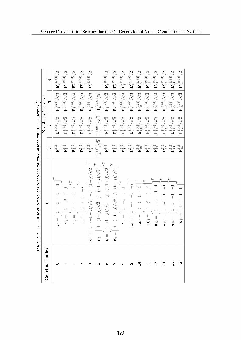
Advanced Transmission Schemes for the 4th Generation of Mobile Communication Systems
TableB.2.:LTERelease
8precoder
codebookfortransm
issionwithfourantennas[3]
Codebookindex
ui
Numberoflayersr
12
34
0u0
=[ 1
−1−
1−
1] T
F{1}
0F{1
4}
0/√
2F{1
24}
0/√
3F{1
234}
0/2
1u1
=[ 1
−j
1j] T
F{1}
1F{1
4}
1/√
2F{1
24}
1/√
3F{1
234}
1/2
2u2
=[ 1
1−
11] T
F{1}
2F{1
4}
2/√
2F{1
24}
2/√
3F{1
234}
2/2
3u3
=[ 1
j1−j] T
F{1}
3F{1
4}
3/√
2F{1
24}
3/√
3F{1
234}
3/2
4u4
=[ 1
(−1−j)/√
2−j
(1−j)/√
2] T
F{1}
4F{1
4}
4/√
2F{1
24}
4/√
3F{1
234}
4/2
5u5
=[ 1
(1−j)/√
2j
(−1−j)/√
2] T
F{1
4}
5/√
2F{1
24}
5/√
3F{1
234}
5/2
6u6
=[ 1
(1+j)/√
2−j
(−1
+j)/√
2] T
F{1}
6F{1
4}
6/√
2F{1
24}
6/√
3F{1
234}
6/2
7u6
=[ 1
(−1
+j)/√
2j
(1+j)/√
2] T
F{1}
7F{1
4}
7/√
2F{1
24}
7/√
3F{1
234}
7/2
8u8
=[ 1
−1
11] T
F{1}
8F{1
4}
8/√
2F{1
24}
8/√
3F{1
234}
8/2
9u9
=[ 1
−j−
1−j] T
F{1}
9F{1
4}
9/√
2F{1
24}
9/√
3F{1
234}
9/2
10
u10
=[ 1
11−
1] T
F{1}
10
F{1
4}
10/√
2F{1
24}
10
/√3
F{1
234}
10
/2
11
u11
=[ 1
j−
1j] T
F{1}
11
F{1
4}
11/√
2F{1
24}
11
/√3
F{1
234}
11
/2
12
u12
=[ 1
−1−
11] T
F{1}
12
F{1
4}
12/√
2F{1
24}
12
/√3
F{1
234}
12
/2
13
u13
=[ 1
−1
1−
1] T
F{1}
13
F{1
4}
13/√
2F{1
24}
13
/√3
F{1
234}
13
/2
14
u14
=[ 1
1−
1−
1] T
F{1}
14
F{1
4}
14/√
2F{1
24}
14
/√3
F{1
234}
14
/2
15
u15
=[ 1
11
1] T
F{1}
15
F{1
4}
15/√
2F{1
24}
15
/√3
F{1
234}
15
/2
120

Bibliography
Bibliography
[1] 3GPP TR 25.814 V7.1.0, �Physcial layer aspects for evolved universal terrestrial radioaccess (UTRA),� Sep. 2006.
[2] 3GPP TS 25.996 V8.0.0, �Spatial channel model for multiple input multiple output(MIMO) simulations,� Dec. 2008.
[3] 3GPP TS 36.211 V8.9.0, �Evolved universal terrestrial radio access (E-UTRA): Physicalchannels and modulation (Release 8),� Dec. 2009.
[4] 3GPP TS 36.211 V9.1.0, �Evolved universal terrestrial radio access (E-UTRA): Physicalchannels and modulation (Release 9),� Mar. 2010.
[5] 3GPP TS 36.213 V8.8.0, �Evolved universal terrestrial radio access (E-UTRA): Physicallayer procedures,� Sep. 2009.
[6] 3GPP TS 36.214 V8.7.0, �Evolved universal terrestrial radio access (E-UTRA): Physicallayer � measurements,� Sep. 2009.
[7] 3GPP TS 36.420 V8.1.0, �Evolved universal terrestrial radio access network (E-UTRAN): X2 general aspects and principles,� Dec. 2008.
[8] 3GPP TS 36.423 V8.9.0, �Evolved universal terrestrial radio access network (E-UTRAN): X2 application protocol (X2AP),� Mar. 2010.
[9] W. Ajib and D. Haccoun, �An overview of scheduling algorithms in MIMO-based fourth-generation wireless systems,� IEEE Network, pp. 43�48, Sep. 2005.
[10] P. Almers, E. Bonek, A. Burr, N. Czink, M. Debbah, V. Degli-Esposti, H. Hofstetter,P. Kyösti, D. Laurenson, G. Matz, A. Molisch, C. Oestges, and H. Özcelik, �Survey ofchannel and radio propagation models for wireless MIMO systems,� EURASIP Journal
on Wireless Communications and Networking, Jan. 2007.
[11] D. Astely, E. Dahlman, A. Furuskär, Y. Jading, M. Lindström, and S. Parkvall, �LTE:The evolution of mobile broadband,� IEEE Communications Magazine, vol. 47, no. 4,pp. 44�50, Apr. 2009.
[12] D. Baum, J. Hansen, and J. Salo, �An interim channel model for beyond-3G systems:extending the 3GPP spatial channel model (SCM),� in IEEE Vehicular Technology
Conference, May 2005.
[13] F. Boccardi and H. Huang, �A near-optimum technique using linear precoding forthe MIMO broadcast channel,� in Proc. IEEE International Conference on Acoustics,
Speech, and Signal Processing, Apr. 2007.
121

Advanced Transmission Schemes for the 4th Generation of Mobile Communication Systems
[14] H. Boche, �Future research challenges for mobile networks,� in Proc. Deutsche TelekomLaboratories Open Conference on Next Generation Mobile Networks, Oct. 2010.
[15] G. Boudreau, J. Panicker, N. Guo, R. Chang, N. Wang, and S. Vrzic, �Interference coor-dination and cancellation for 4G networks,� IEEE Communications Magazine, vol. 47,no. 4, pp. 74�81, Apr. 2009.
[16] K. Brueninghaus, D. Astely, T. Sälzer, S. Visuri, A. Alexiou, S. Karger, and G.-A.Seraji, �Link performance models for system level simulations of broadband radio accesssystems,� in Proc. IEEE International Symposium on Personal, Indoor and Mobile
Radio Communications, Sep. 2005.
[17] G. Caire and S. Shamai, �On the achievable throughput of a multiantenna Gaussianbroadcast channel,� IEEE Transactions on Information Theory, vol. 49, no. 7, pp.1691�1706, Jul. 2003.
[18] G. Caire, G. Taricco, and E. Biglieri, �Capacity of bit-interleaved channels,� Electronicletters, vol. 32, no. 12, pp. 1060�1061, Jun. 1996.
[19] F. Calabrese, C. Rosa, M. Anas, P. Michaelsen, K. Pedersen, and P. Mogensen, �Adap-tive transmission bandwidth based packet scheduling for LTE uplink,� in Proc. IEEE
Vehicular Technology Conference, Sep. 2008.
[20] G. Calcev, D. Chizhik, B. Göransson, S. Howard, H. Huang, A. Kogiantis, A. Molisch,A. Moustakas, D. Reed, and H. Xu, �A wideband spatial channel model for system-widesimulations,� IEEE Transactions on Vehicular Technology, vol. 56, no. 2, pp. 389�403,Mar. 2007.
[21] D. Chase, �Code combining � a maximum-likelihood decoding approach for combiningan arbitrary number of noisy packets,� IEEE Transactions on Communications, vol. 33,pp. 385�393, May 1985.
[22] L.-U. Choi and R. Murch, �A transmit preprocessing technique for multiuser MIMOsystems using a decomposition approach,� IEEE Transactions on Wireless Communi-
cations, vol. 3, no. 1, pp. 20�24, Jan. 2004.
[23] D. Chu, �Polyphase codes with good periodic correlation properties,� IEEE Transac-
tions on Information Theory, vol. 18, no. 4, pp. 531�532, Jul. 1972.
[24] L. J. Cimini, �Analysis and simulation of digital mobile channel using orthogonal fre-quency division multiplexing,� IEEE Transactions on Communications, vol. 33, pp.665�675, Jul. 1985.
[25] J. Conway, R. Hardin, and N. Sloane, �Packing lines, planes, etc.: Packings in Grass-mannian spaces,� Experimental Mathematics, vol. 5, no. 2, pp. 139 � 159, Apr. 1996.
[26] M. Costa, �Writing on dirty paper,� IEEE Transactions on Information Theory, vol. 29,no. 3, pp. 439�441, May 1983.
[27] E. Dahlman, S. Parkvall, J. Sköld, and P. Beming, 3G evolution - HSPA and LTE for
mobile broadband. Oxford, United Kingdom: Elsevier Academic Press, 2007.
122
Bibliography
[28] E. Damosso and L. Correia, Digital mobile radio towards future generation systems.Brussels, Belgium: European Commision, 1999.
[29] G. Dietl and G. Bauch, �Linear precoding in the downlink of limited feedback multiuserMIMO systems,� in Proc. IEEE Global Telecommunications Conference, Dec. 2007.
[30] P. Ding, D. Love, and M. Zoltowski, �Multiple antenna broadcast channels with shapefeedback and limited feedback,� IEEE Transactions on Signal Processing, vol. 55, no. 7,pp. 3417 � 3428, Jul. 2007.
[31] L. Falconetti and C. Hoymann, �Codebook based inter-cell interference coordination forLTE,� in Proc. IEEE International Symposium on Personal, Indoor and Mobile Radio
Communications, Sep. 2010.
[32] G. Fodor, C. Koutsimanis, A. Rácz, N. Reider, A. Simonsson, and W. Müller, �Intercellinterference coordination in OFDMA networks and in the 3GPP Long Term Evolutionsystem,� Journal of Communications, pp. 445�453, Aug. 2009.
[33] I. Forkel, M. Schinnenburg, and M. Ang, �Generation of two-dimensional correlatedshadowing for mobile radio network simulation,� in Proc. International Symposium on
Wireless Personal Multimedia Communications, Sep. 2004.
[34] G. Foschini, G. Golden, and R. Valenzuela, �Simpli�ed processing for high spectrale�ciency wireless communication employing multi-element arrays,� IEEE Journal on
Selected Areas in Communications, vol. 17, no. 11, pp. 1841�1852, Nov. 1999.
[35] P. Frank, A. Müller, H. Droste, and J. Speidel, �Cooperative interference-aware jointscheduling for the 3GPP LTE uplink,� in Proc. IEEE International Symposium on
Personal, Indoor and Mobile Radio Communications, Sep. 2010.
[36] P. Frank, A. Müller, and J. Speidel, �Fair performance comparison between CQI- andCSI-based MU-MIMO for the LTE downlink,� in Proc. European Wireless Conference,Apr. 2010.
[37] ��, �Inter-site joint detection with reduced backhaul capacity requirements for the3GPP LTE uplink,� in Proc. IEEE Vehicular Technology Conference, Sep. 2010.
[38] ��, �Performance of CSI-based multi-user MIMO for the LTE downlink,� in Proc.
International Wireless Communications and Mobile Computing Conference, Jun. 2010.
[39] M. Fuchs, G. D. Galdo, and M. Haardt, �Low complexity space-time-frequency schedul-ing for MIMO systems with SDMA,� IEEE Transactions on Vehicular Technology,vol. 56, no. 6, pp. 2775�2784, Sep. 2007.
[40] A. Gersho and R. Gray, Vector quantization and signal compression. Norwell, Mas-sachusetts: Kluwer Academic Publishers, 1992.
[41] D. Gesbert, M. Kountouris, R. Heath, C.-B. Chae, and T. Sälzer, �From single userto multiuser communications: shifting the MIMO paradigm,� IEEE Signal Processing
Magazine, pp. 36�46, Sep. 2007.
[42] L. Godara, �Application of antenna arrays to mobile communications part II: Beam-forming and direction-of-arrival considerations,� Proc. of the IEEE, vol. 85, pp. 1195 �1245, Aug. 1997.
123

Advanced Transmission Schemes for the 4th Generation of Mobile Communication Systems
[43] A. Goldsmith, Wireless communications. New York, USA: Cambridge UniversityPress, 2005.
[44] G. Golub and C. V. Loan, Matrix computations. Baltimore, USA: The Johns HopkinsUniversity Press, 1996.
[45] M. Gudmundson, �Correlation model for shadow fading in mobile radio systems,� Elec-tronics Letters, vol. 27, no. 23, pp. 2145�2146, Nov. 1991.
[46] S. H. Han and J. H. Lee, �An overview of peak-to-average power ratio reduction tech-niques for multicarrier transmission,� IEEE Wireless Communications, vol. 12, no. 2,pp. 56�65, Apr. 2005.
[47] B. Hassibi and M. Sharif, �Fundamental limits in MIMO broadcast channels,� IEEEJournal on Selected Areas in Communications, vol. 25, no. 7, pp. 1333�1344, Sep. 2007.
[48] X. He, K. Niu, Z.He, and J. Lin, �E�ective SINR approach of link to system mappingin OFDM/multi-carrier mobile network,� in Proc. International Workshop on Cross
Layer Design, Sep. 2007.
[49] H. Holma and A. Toskala, LTE for UMTS � OFDMA and SC-FDMA based radio access.Chichester, United Kingdom: John Wiley and Sons, 2009.
[50] C. Hoymann, L. Falconetti, and R. Gupta, �Distributed uplink signal processing ofcooperating base stations based on IQ sample exchange,� in Proc. IEEE International
Conference on Communications, Jun. 2009.
[51] H. Huang, M. Trivellato, A. Hottinen, M. Sha�, and R. V. P. Smith, �Increasing down-link cellular throughput with limited network MIMO coordination,� IEEE Transactions
on Wireless Communications, vol. 8, no. 6, pp. 2983�2989, Jun. 2009.
[52] N. Jindal, �MIMO broadcast channels with digital channel feedback,� in Proc. AsilomarConference on Signal, Systems and Computers, Oct. 2006.
[53] ��, �MIMO broadcast channels with �nite-rate feedback,� IEEE Transactions on
Information Theory, vol. 52, no. 11, pp. 5045�5060, Nov. 2006.
[54] N. Jindal and A. Goldsmith, �Dirty-paper coding versus TDMA for MIMO broadcastchannels,� IEEE Transactions on Information Theory, vol. 51, no. 5, pp. 1783�1794,May 2005.
[55] M. Karakayali, G. Foschini, and R. Valenzuela, �Network coordination for spectrally ef-�cient communications in cellular systems,� IEEE Wireless Communications Magazine,vol. 13, no. 4, pp. 56�61, Aug. 2006.
[56] J. Kim, W. Zirwas, and M. Haardt, �BER criterion and codebook construction for�nite-rate precoded spatial multiplexing with linear receivers,� EURASIP Journal on
Advances in Signal Processing, Jan. 2008.
[57] K. Kusume, G. Dietl, T. Abe, H. Taoka, and S. Nagata, �System level performance ofdownlink MU-MIMO transmission for 3GPP LTE-Advanced,� in Proc. IEEE Vehicular
Technology Conference, May 2010.
124

Bibliography
[58] J. Laiho, A. Wacker, and T. Novosad, Radio Network Planning and Optimization for
UMTS. Chichester, United Kingdom: John Wiley and Sons, 2002.
[59] J. Lee, J.-K. Han, and J. Zhang, �MIMO technologies in 3GPP LTE and LTE-Advanced,� EURASIP Journal on Wireless Communications and Networking, May2009.
[60] S. Lin and D. Costello, Error control coding. Englewood Cli�s, New Jersey: Prentice-Hall, 1983.
[61] Y. Linde, A. Buzo, and R. M. Gray, �An algorithm for vector quantizer design,� IEEETransactions on Communications, vol. 28, no. 1, pp. 84�95, Jan. 1980.
[62] D. Love and R. Heath, �Limited feedback unitary precoding for spatial multiplexingsystems,� IEEE Transactions on Information Theory, vol. 51, no. 8, pp. 2967 � 2976,Aug. 2005.
[63] D. Love, R. Heath, V. Lau, D. Gesbert, B. Rao, and M. Andrews, �An overview oflimited feedback in wireless communication systems,� IEEE Journal on Selected Areas
in Communications, vol. 26, no. 8, pp. 1341�1365, Oct. 2008.
[64] D. Love, R. Heath, W. Santipach, and M. Honig, �What is the value of limited feedbackfor MIMO channels?� IEEE Communications Magazine, vol. 42, no. 10, pp. 54�59,Oct. 2004.
[65] D. Love, R. Heath, and T. Strohmer, �Grassmannian beamforming for multiple-inputmultiple-output wireless systems,� IEEE Transactions on Information Theory, vol. 49,no. 10, pp. 2735�2747, Oct. 2003.
[66] C. Lv, S. Zhou, Y. Li, and T. Wang, �Low complexity scheduling technique for multi-user MIMO systems,� in Proc. IEEE Vehicular Technology Conference, May 2008.
[67] X. Mao, A. Maaref, and K. Teo, �Adaptive soft frequency reuse for inter-cell inter-ference coordination in SC-FDMA based 3GPP LTE uplinks,� in Proc. IEEE Global
Telecommunications Conference, Dec. 2008, pp. 36�46.
[68] P. Marsch and G. Fettweis, �On uplink network MIMO under a constrained backhauland imperfect channel knowledge,� in Proc. IEEE International Conference on Com-
munications, Jun. 2009.
[69] ��, Coordinated multi-point in wireless communications � From theory to practice.Cambridge, Massachusetts: Cambridge University Press, 2011.
[70] V. H. McDonald, �The cellular concept,� Bell System Technology Journal, pp. 15�49,Jan. 1979.
[71] B. Mielczarek and W. Krzymien, �Vector quantization of channel information in lin-ear multi-user MIMO systems,� in Proc. IEEE International Symposium on Spread
Spectrum Techniques and Applications, Aug. 2006.
[72] M. Morelli and U. Mengali, �A comparison of pilot-aided channel estimation methodsfor OFDM systems,� IEEE Transactions on Signal Processing, vol. 49, pp. 3065�3073,Dec. 2001.
125

Advanced Transmission Schemes for the 4th Generation of Mobile Communication Systems
[73] A. Müller and P. Frank, �Cooperative interference prediction for enhanced link adapta-tion in the 3GPP LTE uplink,� in Proc. IEEE Vehicular Technology Conference, May2010.
[74] A. Müller, P. Frank, and J. Speidel, �Performance of the LTE uplink with intra-site jointdetection and joint link adaptation,� in Proc. IEEE Vehicular Technology Conference,May 2010.
[75] H. Myung, J. Lim, and D. Goodman, �Single carrier FDMA for uplink wireless trans-mission,� IEEE Vehicular Technology Magazine, vol. 1, no. 3, pp. 30�38, Sep. 2006.
[76] M. Nakamura, Y. Awad, and S. Vadgama, �Adaptive control of link adaptation forhigh speed downlink packet access (HSDPA) in W-CDMA,� in Proc. International
Symposium on Wireless Personal Multimedia Communications, Oct. 2002.
[77] J. Padgett, C. Günther, and T. Hattori, �Overview of wireless personal communica-tions,� IEEE Communications Magazine, vol. 33, pp. 28�41, Jan. 1995.
[78] S. Parkvall and D. Astely, �The evolution of LTE towards IMT-Advanced,� Journal ofCommunications, vol. 4, no. 3, pp. 146 � 154, Apr. 2009.
[79] V. Pless, W. Hu�man, and R. Brualdi, Handbook of coding theory, volume II. Ams-terdam, Netherlands: Elsevier Science B.V., 1998.
[80] A. Pokhariyal, K. Pedersen, G. Monghal, I. Kovacs, C. Rosa, T. Kolding, and P. Mo-gensen, �HARQ aware frequency domain packet scheduler with di�erent degrees offairness for the UTRAN long term evolution,� in Proc. IEEE Vehicular Technology
Conference, Apr. 2007.
[81] M. Pursley and S. Sandberg, �Incremental-redundancy transmission for meteor-burstcommunications,� IEEE Transactions on Communications, vol. 39, pp. 689�702, May1991.
[82] N. Ravindran and N. Jindal, �Limited feedback-based block diagonalization for theMIMO broadcast channel,� IEEE Journal on Selected Areas in Communications,vol. 26, no. 8, pp. 1473 � 1482, Oct. 2008.
[83] M. Roberts, M. Temple, R. Mills, and R. Raines, �Evolution of the air interface of cel-lular communications systems toward 4G realization,� IEEE Communications Surveys
& Tutorials, vol. 8, no. 1, pp. 2�23, Mar. 2006.
[84] J. Roh and B. Rao, �Design and analysis of MIMO spatial multiplexing systems withquantized feedback,� IEEE Transactions on Signal Processing, vol. 54, no. 8, pp. 2874� 2886, Aug. 2006.
[85] A. Sanderovich, O. Somekh, H. Poor, and S. Shamai, �Uplink macro diversity withlimited backhaul cellular networks,� IEEE Transactions on Information Theory, vol. 55,no. 8, pp. 3457 � 3478, Aug. 2009.
[86] S. Sesia, I. Tou�k, and M. Baker, The UMTS Long Term Evolution: From theory to
practice. Chichester, United Kingdom: John Wiley and Sons, 2009.
126
Bibliography
[87] Z. Shen, R. Chen, J. Andrews, R. Heath, and B. Evans, �Low complexity user selectionalgorithms for multiuser MIMO systems with block diagonalization,� IEEE Transac-
tions on Signal Processing, vol. 54, no. 9, pp. 3658�3663, Sep. 2006.
[88] B. Song, F. Roemer, and M. Haardt, �E�cient channel quantization scheme for multi-user MIMO broadcast channels with RBD precoding,� in Proc. IEEE International
Conference on Acoustics, Speech and Signal Processing, Apr. 2008.
[89] J. Speidel, �Multiple-Input Multiple-Output (MIMO)� Drahtlose Nachrichtenübertra-gung hoher Bitrate und Qualität mit Mehrfachantennen,� TeleKommunikation Aktuell,vol. 59, Jul. 2005.
[90] ��, �Space-time wireless communications,� Institute of Telecommunications Lecture
at the University of Stuttgart, 2010.
[91] J. Speidel, H. Droste, and P. Frank, �LTE-Advanced,� in Proc. Deutsche Telekom Lab-
oratories Open Conference on Next Generation Mobile Networks, Oct. 2010.
[92] Q. Spencer and M. Haardt, �Capacity and downlink transmission algorithms for amulti-user MIMO channel,� in Proc. Asilomar Conference on Signals, Systems and
Computers, Nov. 2002.
[93] Q. Spencer, C. Peel, A. Swindlehurst, and M. Haardt, �An introduction to the multi-user MIMO downlink,� IEEE Communications Magazine, pp. 60�67, Oct. 2004.
[94] Q. Spencer, A. Swindlehurst, and M. Haardt, �Zero-forcing methods for downlink spa-tial multiplexing in multiuser MIMO channels,� IEEE Transactions on Signal Process-
ing, vol. 52, no. 2, pp. 461�471, Feb. 2004.
[95] V. Stankovic and M. Haardt, �Generalized design of multi-user MIMO precoding ma-trices,� IEEE Transactions on Wireless Communications, vol. 7, no. 3, pp. 953�961,Mar. 2008.
[96] V. Stencel, A. Müller, and P. Frank, �LTE-Advanced � a further evolutionary step fornext generation mobile networks,� in Proc. International Conference Radioelektronika,Apr. 2010.
[97] G. Stüber, Principles of mobile communication. Norwell, Massachusetts: KluwerAcademic Publishers, 2001.
[98] M. Trivellato, F. Boccardi, and H. Huang, �On transceiver design and channel quan-tization for downlink multiuser MIMO systems with limited feedback,� IEEE Journal
on Selected Areas in Communications, vol. 26, no. 8, pp. 1494 � 1504, Oct. 2008.
[99] ��, �On transceiver design and channel quantization for downlink multiuser MIMOsystems with limited feedback,� IEEE Journal on Selected Areas in Communications,vol. 26, no. 8, pp. 1494 � 1504, Oct. 2008.
[100] D. Tse and P. Viswanath, Fundamentals of Wireless Communications. Cambridge,Massachusetts: Cambridge University Press, 2005.
[101] E. Tuomaala and H. Wang, �E�ective SINR approach of link to system mapping inOFDM/multi-carrier mobile network,� in Proc. International Conference on Mobile
Technology, Applications and Systems, Nov. 2005.
127

Advanced Transmission Schemes for the 4th Generation of Mobile Communication Systems
[102] R. van Nee and R. Prasad, OFDM for wireless multimedia communications. Norwood,Massachusetts: Artech House Publishers, 2000.
[103] S. Venkatesan, �Coordinating base stations for greater uplink spectral e�ciency in acellular network,� in Proc. IEEE International Symposium on Personal, Indoor and
Mobile Radio Communications, Sep. 2007.
[104] P. Viswanath, D. Tse, and R. Laroia, �Opportunistic beamforming using dumb anten-nas,� IEEE Transactions on Information Theory, vol. 48, no. 6, pp. 1277�1294, Jun.2002.
[105] N. Wiener, Extrapolation, interpolation, and smoothing of stationary time series. NewYork, New Yersey: John Wiley & Sons, Ltd, 1949.
[106] J. Wozencraft and M. Horstein, �Digitalised communication over two-way channels,� inProc. London Symposium on Information Theory, Sep. 1960.
[107] F. Xiangning, C. Si, and Z. Xiaodong, �An inter-cell interference coordination tech-nique based on users' ratio and multi-level frequency allocations,� in Proc. of the Inter-national Conference on Wireless Communications, Networking and Mobile Computing,Sep. 2007, pp. 799 � 802.
[108] T. Yoo, N. Jindal, and A. Goldsmith, �Finite-rate feedback MIMO broadcast channelswith a large number of users,� in Proc. IEEE International Symposium on Information
Theory, Jul. 2006.
[109] S. Zhou and B. Li, �BER criterion and codebook construction for �nite-rate precodedspatial multiplexing with linear receivers,� IEEE Transactions on Signal Processing,vol. 54, no. 5, pp. 1653�1665, Jan. 2006.
128

Publications of the author
Publications of the author
• P. Frank, A. Müller, J. Speidel, "Fair performance comparison between CQI- and CSI-based MU-MIMO for the LTE downlink", in Proc. European Wireless Conference,Apr. 2010.
• V. Stencel, A. Müller, P. Frank, "LTE-Advanced � a further evolutionary step for nextgeneration mobile networks", in Proc. International Conference Radioelektronika, Apr.2010.
• A. Müller, P. Frank, J. Speidel, "Performance of the LTE uplink with intra-site jointdetection and joint link adaptation", in Proc. IEEE Vehicular Technology Conference,May 2010.
• A. Müller, P. Frank, "Cooperative interference prediction for enhanced link adaptationin the 3GPP LTE uplink", in Proc. IEEE Vehicular Technology Conference, May 2010.
• P. Frank, A. Müller, J. Speidel, "Performance of CSI-based multi-user MIMO for theLTE downlink", in Proc. International Wireless Communications and Mobile Comput-ing Conference, Jun. 2010.
• P. Frank, A. Müller, J. Speidel, "Inter-site joint detection with reduced backhaul ca-pacity requirements for the 3GPP LTE uplink", in Proc. IEEE Vehicular TechnologyConference, Sep. 2010.
• P. Frank, A. Müller, H. Droste, J. Speidel, "Cooperative interference-aware joint sche-duling for the 3GPP LTE uplink", in Proc. IEEE International Symposium on Per-sonal, Indoor and Mobile Radio Communications, Sep. 2010.
• J. Speidel, H. Droste, P. Frank, "LTE-Advanced", in Proc. Deutsche Telekom Labora-tories Open Conference on Next Generation Mobile Networks, Oct. 2010.
Book chapters of the author
• P. Marsch, G. Fettweis, "Coordinated multi-point in wireless communications � Fromtheory to practice", Cambridge, Massachusetts: Cambridge University Press, 2011,chapter 5.2 & 14.3
Standard contributions of the author
• 3GPP R1-094595, "Coordinated link adaptation based on multi-cell channel estimationin the LTE-A uplink", TSG RAN WG1 Meeting # 59, Nov. 2009.
Patents of the author
• P. Frank, A. Müller, H. Droste "Method for improved link adaption in cellular wirelessnetworks", WO/2010/142441, publication Dec. 2010.
129