addressing the sustainable energy conversion in … · addressing the sustainable energy conversion...
TRANSCRIPT

Addressing the Sustainable Energy Conversion in Electric Railway Vehicles with Traction Synchronous Motors
CORNELIA A. BULUCEA1, DORU A. NICOLA1, DANIEl C. CISMARU 1,
NIKOS E. MASTORAKIS2, CARMEN A. BULUCEA3, CONSTANTIN BRINDUSA4,
1University of Craiova, Faculty of Electrical Engineering, Craiova 200440, Romania;
2Technical University of Sofia, Industrial Engineering Department, Sofia, Bulgaria & Military Institutions of University Education (ASEI), Hellenic Naval Academy, Piraeus 18539, Greece;
3University of Medicine and Pharmacy of Craiova, Craiova 200349, Romania; 4University Constantin Brancusi of Targu Jiu, Targu Jiu, Romania,
E-Mails: [email protected]; [email protected]; [email protected]; [email protected]; [email protected]; [email protected]
Abstract: This paper addresses some aspects illustrating sustainable energy conversion processes during the operation of electric railway vehicles with traction synchronous motors. Increasing efforts are being expended to enhance the sustainability of transportation technologies and systems, and supporting transport systems’ sustainability is a key way of thinking towards cleaner production. In line with this idea, this paper addresses the operation sustainability of electric railway vehicles with traction synchronous motors, highlighting the chain of interactions among the main electric equipment on an electrically driven railway system. The paper supports the findings that electric traction drive systems using traction synchronous motors powered by network-side converters and machine-side converters enhance the sustainable operation of railway trains. Key-Words: electromagnetic torque, high speed electric train, railway vehicle, sustainability dynamics, synchronous motor 1 Introduction In line with the framework of cleaner production, to address meaningfully many of the problems facing railway vehicles, conditions for the performance of sustainable transportation systems must be formulated [1-5]. Correspondingly, sustainability concepts can help understand the efficiencies of electrically driven systems and guide improvement efforts [1-5].
According to the term defined by United Nation Environmental Programme in 1990, cleaner production requires a new way of thinking about processes and products, and about how they can be made less harmful to humans and the environment [6-7]. Within the conceptual framework of cleaner production improvements of technology and changes in equipment design should suggest better choices in use of materials and energy in manufacturing and operation of industrial systems [5-7]. Improved control and automatisation represent key concepts of cleaner production strategies [6-8]. Green products and systems are generally produced in a manner that consumes
fewer natural resources or uses them in a more sustainable way, and they may involve high exergy efficiency in their manufacture and operation [4-5].
The sustainability of an electric transportation system is based on technical performance, safety, energy and exergy efficiency, mitigated environmental impact, economics and societal acceptance [1-3].Costs should reflect value, which is doubtless associated with sustainability aspects [1-5]. Addressing the sustainability of traction and braking operation of the electric vehicles constitutes a challenge in electric transportation research. 2 Structure of Main Electric Circuits of Railway Vehicles with Traction Synchronous Motors In order to be used as a traction motor on high speed trains (namely, the French TGV), the synchronous motor (being an electric motor with rotating field) is needing a variable frequency three-phase supply [9-15]. It results implicitly the necessity of the machine converter (MC) in the power circuit. The MC is a current inverter (CI) with a three-phase bridge (with
WSEAS TRANSACTIONS on POWER SYSTEMSCornelia A. Bulucea, Doru A. Nicola, Daniel C. Cismaru, Nikos E. Mastorakis, Carmen A. Bulucea, Constantin Brindusa
E-ISSN: 2224-350X 495 Volume 9, 2014

6 thyristor branches linked as a three-phase bridge) which operates being commutated by the counter-electromotive forces (CEMF) (-e0) induced in the three-phase stator winding of the supplied synchronous motor [9-11].
One could notice that problems related to the natural commutation appear solely at very low speed, when the CEMF amplitude is small (and consequently, insufficient for ensuring the commutation). In such situation (from the starting regime up to 5-10% of the maximum speed vmax) the commutation adjustment is imposed. The devices for the assisting commutation are quite simple and don’t have a hard weight (for instance, a weight of 70 kg for a 6000 kW locomotive). Moreover, by using the signals regarding the rotor position and speed at the inverter control, the synchronous motor will drive (or pilot) the current inverter which is supplying it, this way being eliminated the risks of synchronism loss, whatever is the rotor speed. Hence, the traction synchronous motor is a self-piloted motor [9-15].
As a pattern, the operation of a self-piloted synchronous motor supplied by a current inverter source is similar to the DC motor with fixed armature and rotating inductor. According to this scenario, the speed regulation of the self-piloted synchronous motor will be ensured similarly to the DC motor with separate excitation [17-18]. Concretely, it is performed the change of voltage of the DC intermediary circuit with single phase bridges with phase regulation (mixed bridges or fully controlled bridges) in the case of the supply from a AC contact line, or there are utilized electronic DC drives (DC/DC converters) in the case of the supply from a DC contact line. In order to obtain high speeds there is performed the field weakening [9-15, 18-20].
Unlike the electric railway vehicle with induction
motors, during the electric power transmission on
the vehicle with synchronous motors the amplitude regulation functions are completely separated from those of frequency regulation. Actually, the voltage variation is enabled as in classic traction with DC motors by the electronic DC drives (DC/DC converters) or by mixed single-phase half-controlled bridge rectifier by asymmetric type. Conversely, the frequency variation is provided by the current inverters (CI) through which the traction synchronous motors are powered.
Consequently, the electric trains with traction
synchronous motors entail compulsory two conversion stages of the electric energy. Specifically, it is imposed the presence of the network converter (NC) both when the railway electric vehicle is powered from an AC contact line (see Figure 1) and when the vehicle is supplied from a DC contact line (see Figure 2).
As a traction motor, the synchronous motor is operating in a self-piloted regime, the control pulses of the current inverter thyristors (synchronized with the induced voltages) being correlated with the rotor position due to the position transducer PT. In the operation at low speed, when the counter-electromotive forces can not anymore ensure the commutation of the current inverter thyristors it is carried out the “assisted commutation” performed by the auxiliary device AC.
In the case of electric locomotives and urban trains with traction synchronous motors supplied from an AC contact line, the network converter NC is encompassing a system of single-phase rectifiers (full or part controlled) connected in series (in order to improve the power factor). In contrast, when the electric railway vehicle is powered by a DC line, the network converter is a classic chopper (with operation in 1 or 2 quadrants).
Consequently, in both situations the structure of the network converters is similar to classic solutions with rectifiers and choppers. Conversely it is imposed to enhance the analysis of the system inverter –
Fig.2 Power circuits’ structure of electrical railway vehicle with
traction synchronous motors supplied from DC contact line NF = network filter; NC = network converter; AC = assisted
commutation device; L = smoothing coil (with iron core); MC=machine converter; SM=synchronous motor;
PT=position transducer
Fig.1 Power circuits’ structure of electrical railway vehicle with
traction synchronous motors supplied from AC contact line NC = network converter; AC = assisted commutation device;
L = smoothing coil (with iron core); MC = machine converter; SM =synchronous motor; PT = position transducer
WSEAS TRANSACTIONS on POWER SYSTEMSCornelia A. Bulucea, Doru A. Nicola, Daniel C. Cismaru, Nikos E. Mastorakis, Carmen A. Bulucea, Constantin Brindusa
E-ISSN: 2224-350X 496 Volume 9, 2014

synchronous motor, underlining that its structure is identical for both supply types from the contact line.
In contrast with the case of electric locomotives and urban trains with traction induction motors, the utilization of synchronous motors as electric traction motor does not raise problems related to the electric braking safety. The electric braking might be easily accomplished, since when the contact line power is cut the traction synchronous motors, being excited now from the locomotives batteries will operate as synchronous generators, delivering the electric energy (converted to DC power by the converter bridge) on the electrical braking resistance conveniently sized.
For economic reasons, so far the synchronous motor has been used as traction motor only at high power (800 kW and 1.1 MW) on locomotives and electric trains TFV-A type.
3 Electromagnetic Torque Developed by Synchronous Motor Within the framework of cleaner production, the exergy concept, which is a measure of energy quality, can be used to enhances understanding and help improve the efficiencies of technical systems which convert energy and matter [1-5]. According to the laws of thermodynamics, energy is never destroyed during a process, although it can change from one form to another, but exergy can be destroyed. While energy is a measure of quantity only, exergy is a measure of quantity and quality or usefulness. Energy is often thought of as motion and exergy as work [1-5]. Thus, exergy has an important role to play in increasing efficiencies of energy systems and technologies, within energy optimization and engineering modeling studies.
Since exergy is a measure of the potential of a system to do work, the electromagnetic torque M developed by an electrical motor can be interpreted as the driving force of useful work, i.e. the electric motor output exergy [1-5].
The electromagnetic torque M (respectively, the electromagnetic power PM=M·Ω with Ω=ω/p) developed by any synchronous motor is determined by calculation on basis of the active powers’ balance, as follows: 2
111 3cos3 IRIUpPP JM ××-×××=-= j (1)
)cos(3 21 IRIU
pPM M ×-×××
×=
W= j
w (2)
For generalization, we consider the case of salient pole synchronous motor, referring to the classic phasor diagram depicted in Figure 3, where the components of the current I and voltage U on the axes d and q are:
Y×=Y×= cos;sin IIII qd (3) qq cos;sin ×=×= UUUU qd
(4) If there is taken into consideration that φ = ψ + θ,
and the function cos (ψ+θ) is trigonometrically developed as:
qqqqj sincossinsincoscoscos ×-×=×Y×-×Y×=× dq IIIII (5)
and in the expression of active power (U·I·cosφ) the components Ud and Uq are highlighted:
ddqqdq UIUIUIUIIU ×-×=××-×=×× )sin()cos(cos qqj (6)
then the formula (2) for the calculation of electromagnetic torque M becomes: )(3 2
1 IRUIUIp
M ddqq ×-×-×××
=w
(7)
Using again the phasor diagram (Fig.3.a), by projection of the phasors’ contour on the axes d and q, the voltage equations in scalar form of components are obtained as:
ddqpq
qqdd
IXIREU
IXIRU
×+×-=
×+×-=
10
1 (8)
If further the term Iq·Uq - Id·Ud is evaluated as below:
210 )( IRIIXXIEUIUI qdqdqpddqq ×+××-+×=×-× (9)
then the expression of the electromagnetic torque M given by (7) will take the compact form:
])([30 qdqdqp IIXXIE
pM ××-+×
×=
w (10)
At the non-salient synchronous motor, when Xd=Xq=Xs the component caused by the magnetic anisotropy in the formula (10) will not appear anymore. Actually, the final expression of the electromagnetic torque will depend on the type of the power supply of the synchronous motor (voltage source or current source).
q
jy
q
y
j
jj
yy q y
jj
yq
q q
Fig.3 Blondel phasor diagram of synchronous motor with salient poles a) under-excited operation (inductive current curent I ); b) over-excited
operation (capacitive current I)
WSEAS TRANSACTIONS on POWER SYSTEMSCornelia A. Bulucea, Doru A. Nicola, Daniel C. Cismaru, Nikos E. Mastorakis, Carmen A. Bulucea, Constantin Brindusa
E-ISSN: 2224-350X 497 Volume 9, 2014

3.1 Electromagnetic Torque Developed by the Synchronous Motor Supplied from a Three-Phase Sinusoidal Currents’ Source In the case of powering from a three source of sinusoidal currents the current phasor I (through the reference stator winding) is specified by its magnitude |I|=I and initial phase (through the position angle) ψ to the axis q of the rotor. It means that implicitly there are specified the components Id and Iq (3) of the stator current I.
In these supplying conditions the electromagnetic torque MI=M will be determined with relation (10) in which there are performed the substitutions specified by (3), obtaining the expression as follows:
]cossin)(cos[3 20 Y×Y×-+Y××
×= IXXIE
pM qdpI w
(11)
And the final form: ]2sin)(
21cos[3 2
0 Y×-+Y××××
= qdpI XXIIEp
Mw
(12)
On the whole, one could notice the presence of two components MI’ and MI”, so that based on relation (12) it can be written MI = MI’ + MI”.The main component Y××
×= cos3
0' IE
pM pI w
depends on the
excitation degree (namely, the magnitude of current Ie), while the secondary component
Y×-×××
= 2sin)(2
3 2"
qd XXIp
MI w
is determined by the
magnetic asymmetry of the rotor, being present (and non-zero) even in the absence of the synchronous motor excitation. At I=ct., f=ct. and excitation current Ie=ct. (when E0p=ct.), the electromagnetic torque MI depends solely on the load angle ψ.
For the salient pole synchronous motor, the characteristic MI = f(ψ) is represented in Figure 4 by a thick line.
In the case of non-salient pole motors, in which Xd=Xq=Xs the secondary component will not appear
(MI”=0) and the load characteristic MI = f(ψ) is represented just by the main component with a cosine variation.
One could note that if in formula (12) of the torque MI there are performed the substitutions:
ddom
wp LXkwE ×=F
××= ww );2
( 110 and
qq LX ×= w (13)
then the electromagnetic torque expression MI (at the supply in current) becomes:
Y×-×+Y×F
××= 2sin)(2
3cos)2
(3 211 qd
omwI LLI
pIkwpM (14)
In relations (13) and (14) the physical significance of the new quantities are: w1 = the number of turns, in series, on a stator phase of synchronous motor; kw1 = the winding factor of a stator phase; Φom = the maximum value of the main magnetic flux, depending on the magnitude of excitation current Ie, namely Φom=f(Ie); Ld = the longitudinal inductance of stator winding Lq = the transverse inductance of stator winding of synchronous motor.
Particularly, for ψ=0 (when Id=0 and Iq=I), the expression (14) of the electromagnetic torque MI becomes:
IKIkwpMM omom
wII ×F×=×F
×== )2
(3 11' (15)
videlicet MI will get a form that is mathematically identical to the electromagnetic torque M=Cm·Φ·I developed by a DC motor (with collector) with separated excitation.
In relation (15), with K has been denoted the constructive constant
213 11 wkwpK ××= of
synchronous motor. Expression (14) highlights that at Ie=ct., I=ct. and
ψ=ct. the electromagnetic torque MI is constant (and nonzero) and has the same magnitude regardless of the numerical value of the frequency f of the stator currents.
Precisely the existence of nonzero electromagnetic torque at the powering in current (by magnitude I phase shift ψ=ct. related to the counter-electromotive forces Eop) led to the development of synchronous motor applications in electric traction.
On the electric locomotives and urban trains the synchronous motor is powered from a current inverter (thyristorised), with natural commutation, determined exactly by the counter-electromotive forces Eop (induced in the stator windings of the synchronous motor).
In order to ensure the phase shift ψ (of the current fundamental I leading the counter-electromotive
Fig.4 Characteristic representation MI = f(ψ) of
synchronous motor with salient poles at powering from a three-phase source of sinusoidal currents
WSEAS TRANSACTIONS on POWER SYSTEMSCornelia A. Bulucea, Doru A. Nicola, Daniel C. Cismaru, Nikos E. Mastorakis, Carmen A. Bulucea, Constantin Brindusa
E-ISSN: 2224-350X 498 Volume 9, 2014
forces Eop), the control of thyristors’ conduction is based on the signals from a position transducer solidary with the rotor. Consequently the synchronous motor is piloting.
4 Sustainable Operation of Self-Piloted Synchronous Motor On the electric railway vehicles the most convenient source of three-phase currents (to powering the synchronous motor) is the current inverter with natural commutation. The reason of this choice is related to low price, high reliability and smallsize (due mainly to the absence of the auxiliary extinction circuits).
In this context one could remind that the synchronous motor operating is characterized by a three-phase system of induced counter-electromotive forces (-e0A, -e0B, -e0C) which might ensure the commutation of the three-phase bridge thyristors, just as the three-phase alternating voltage network ensured the commutation of rectifier bridge thyristors.
However, to ensure the natural commutation of the thyristorised bridge, the induced counter-electromotive forces must be sufficiently large values, even at low speed, which requires synchronous motor to run over-excited (from start up to rated speed). The over-excitation of synchronous motor will lead to winding currents I that are leading the voltage U (the phase shift φ being by capacitive type, like in Figure 3b), in this case the motor providing also through the terminals the reactive power necessary to the inverter bridge commutation.
In order to ensure the capacitive phase shift of the current, the control of bridge thyristor ignition will be based on signals from a rotor position transducer. This way is correlated the position of current phasor I to the axis d of the rotor.
On the opposite side (the DC side) the autonomous current inverter (CI) must be connected to a DC variable source. Usually, a variable DC source is made up of adjustable DC voltage source (of chopper type or single-phase rectifier bridge with phase adjustment) connected in series with a smoothing coil with iron core, with the inductance L0 of large size.
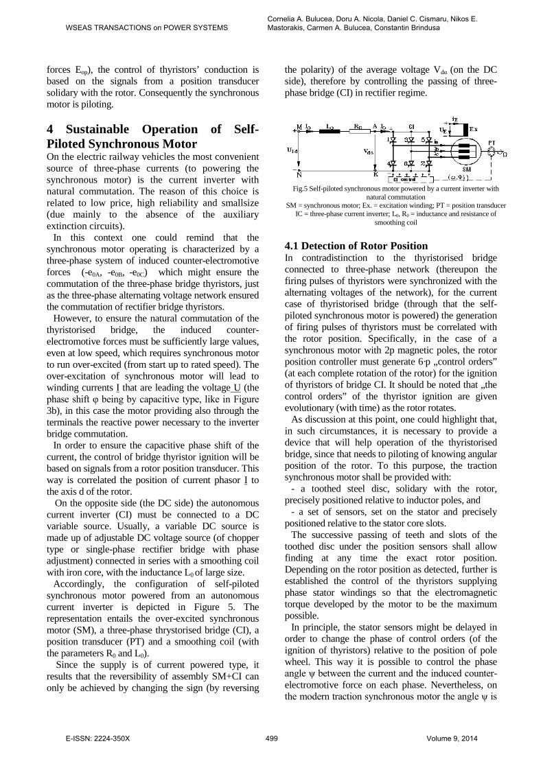
Accordingly, the configuration of self-piloted synchronous motor powered from an autonomous current inverter is depicted in Figure 5. The representation entails the over-excited synchronous motor (SM), a three-phase thrystorised bridge (CI), a position transducer (PT) and a smoothing coil (with the parameters R0 and L0).
Since the supply is of current powered type, it results that the reversibility of assembly SM+CI can only be achieved by changing the sign (by reversing
the polarity) of the average voltage Vdα (on the DC side), therefore by controlling the passing of three-phase bridge (CI) in rectifier regime.
4.1 Detection of Rotor Position In contradistinction to the thyristorised bridge connected to three-phase network (thereupon the firing pulses of thyristors were synchronized with the alternating voltages of the network), for the current case of thyristorised bridge (through that the self-piloted synchronous motor is powered) the generation of firing pulses of thyristors must be correlated with the rotor position. Specifically, in the case of a synchronous motor with 2p magnetic poles, the rotor position controller must generate 6·p „control orders” (at each complete rotation of the rotor) for the ignition of thyristors of bridge CI. It should be noted that „the control orders” of the thyristor ignition are given evolutionary (with time) as the rotor rotates.
As discussion at this point, one could highlight that, in such circumstances, it is necessary to provide a device that will help operation of the thyristorised bridge, since that needs to piloting of knowing angular position of the rotor. To this purpose, the traction synchronous motor shall be provided with:
- a toothed steel disc, solidary with the rotor, precisely positioned relative to inductor poles, and
- a set of sensors, set on the stator and precisely positioned relative to the stator core slots.
The successive passing of teeth and slots of the toothed disc under the position sensors shall allow finding at any time the exact rotor position. Depending on the rotor position as detected, further is established the control of the thyristors supplying phase stator windings so that the electromagnetic torque developed by the motor to be the maximum possible.
In principle, the stator sensors might be delayed in order to change the phase of control orders (of the ignition of thyristors) relative to the position of pole wheel. This way it is possible to control the phase angle ψ between the current and the induced counter-electromotive force on each phase. Nevertheless, on the modern traction synchronous motor the angle ψ is
Fig.5 Self-piloted synchronous motor powered by a current inverter with natural commutation
SM = synchronous motor; Ex. = excitation winding; PT = position transducer IC = three-phase current inverter; L0, R0 = inductance and resistance of
smoothing coil
WSEAS TRANSACTIONS on POWER SYSTEMSCornelia A. Bulucea, Doru A. Nicola, Daniel C. Cismaru, Nikos E. Mastorakis, Carmen A. Bulucea, Constantin Brindusa
E-ISSN: 2224-350X 499 Volume 9, 2014

electronically controlled, by an electronic phase shift of signals generated by the position sensors. Usually, the device to detecting the rotor position is located inside the traction synchronous motor, being situated on the opposite side to the rotor shaft end. 4.2 Current Diagrams Study of joint operation of current inverter and synchronous motor in self-piloted regime can be performed solely in the context of supply scheme from Figure 5. This is the easiest powering at variable frequency of synchronous motor [9-11].
The synchronous motor will be over-excited and
the three-phase induced counter-electromotive forces (-e0A, -e0B, -e0C) of frequency f=ω/2π will be able to drive the commutation of the current inverter thyristors at any speed Ω>Ωmin without the risk of losing synchronism between rotor and rotating magnetic field.
Specifically, at any speed “n” of the rotor of self-piloted synchronous motor (corresponding to the frequency f=p·n/60 of stator currents) through the induced counter-electromotive forces the synchronous motor is piloting the converter which, from the DC current I0, is distributing (on each of the three phases of the stator) current pulses of amplitude ±I0, duration T/3 and a repetition frequency f=1/T=ω/2π which is proportional to the angular mechanical speed of rotor rotation Ω=ω/p. The angular mechanical speed Ω of rotor is resulting from the fundamental equation of motion:
ex M- M= dtd
JW
× (16)
Under the simplifying assumption of a DC current I0 perfectly smooth (when L0→ ∞) and neglecting the commutation durations, the stator currents ia, ib şi ic (flowing through the phases of synchronous motor) will get the forms of variation with time depicted in Figure 6.
In these conditions the fundamentals of stator currents (denoted by ia1, ib1 şi ic1 in Figure 6) form a
three-phase symmetrical current system (by direct sequence) with the frequency f=ω/2π and the effective I1 value given by:
I6
= I 01 ×p
(17)
4.3 Synchronization of Commands Operation of the self-piloted synchronous motor is based on ensuring the capacitive shift phase ψ=ct. between the space phasor of stator currents and the axis q (like in Figure 3). Actually, this condition is verified 6 times during each time period T (by controlling the moments of thyristor ignition relative to the position α=ωt+α0 of the axis d of the rotor). For this purpose, a position transducer TP will provide the rotor positions (with respect to a reference direction of the stator) at which the bridge thyristors of the current inverter IC to be on.
Ideally, if harmonic variation of stator currents, their space phasor i1dq (in the rotor referential (d,q)) will be a fixed phasor, mathematically expressed by:
0116
IIwitheI2 = i )+2
j(1dq ×=×
py
p (18)
In the fixed stator referential the space phasor i1dq will match the expression i1s:
0awap
ayp
a
+=
×
twith
eI32
= ei = )ia +ia +i(32
= i )++2
j(0
j1dqc1
2b1a11s (19)
If the reference stator axis will be overlapping the magnetic axis of phase „A”, and the temporal origin (ωt=0) is chosen when the current ia1 (phase A) passes through a maximum (moment that is coinciding with thyristor ignition timing), the the space phasor i1s will be of the form:
tjtj1s eIeI2 = i ww
p××=×× )6(2 01 (20)
From the expressions (19) and (20) follows that:
) + 2
(- = 0 = + + 2
00 yp
aayp
Þ (21)
That is the rotor position at the moment of ignition of thyristor T2. The other thyristors will be switched on their natural succession (at successive positions of the rotor evenly shifted by π/3 electric radians) as in Figure 6. 4.4 Considering the Current Fundamentals When considering only the fundamentals of stator current, the space phasor i1dq (in the rotating referential d,q) is fixed and gets the expression (in polar form) given by (18). From this relationship, identifying the equivalent algebraic form:
)(22 11
)2
(
11 qd
j
dq IjIeIi ×+×=××=+y
p
(22)
Fig.6 Conduction intervals of three-phase thyristor bridge and shapes of
variation with time of currents ia ,ib şi ic (and their fundamentals ia1 ,ib1 şi ic1)
WSEAS TRANSACTIONS on POWER SYSTEMSCornelia A. Bulucea, Doru A. Nicola, Daniel C. Cismaru, Nikos E. Mastorakis, Carmen A. Bulucea, Constantin Brindusa
E-ISSN: 2224-350X 500 Volume 9, 2014

there are obtained the effective values I1d and I1q of the orthogonal components:
yp
y
yp
y
cos)6(cos
sin)6(sin
011
011
III
III
q
d
=×=
-=×-=
If further in expression (10) of the electromagnetic torque M there are performed the substitutions Id=I1d and Iq=I1q, and, in addition there are used the substitutions (13), finally will result for M=MI:
]sincos)([ yp
yp
2)L - L(I3
- KI6
3p = M qd2020m0I ××××F××× (23)
where the average value of current I0 (which is established in the DC intermediary circuit, see Figure 5) is calculated from the relationship:
R
V - U = I0
dd0
a1 (24)
The sign „-” between the components of the torque MI (13) is caused by the over-excited operation (with the current fundamentals leading the counter-electromotive forces), that means with a capacitive shift (see Figure 3) of the self-piloted synchronous motor.
The sole problem of self-piloted synchronous motor is the starting regime. At low rotational speeds, under 5% of Ωmax, the counter-electromotive force (-e0p) becomes unable to ensure the commutation of the thyristors of the current inverter (CI). In this speed range it is applied the assisted commutation, realized by the device AC (see Figure 1 and Figure 2) through ingenious company solutions.
4.5 Considering the Non-Sinusoidal Currents In very deed, the phase currents ia, ib, ic are strongly distorted as against the ideal sinusoidal shape. Actually, under the simplifying assumptions adopted, each phase current (ia, ib or ic from Figure 6) consists of „rectangular blocks” of amplitude ±I0 (and duration equal to 2π/3) separated by intervals (by duration π/3) in which the currents are null.
Moreover, the fundamentals of phase currents (denoted by ia1, ib1 and ic1 in Figure 6) have equal amplitudes (of magnitude
0I32 p
) and they are shifted,
one lagging another, with the same angle of 2π/3, forming a symmetrical three-phase system of sinusoidal currents, by direct succession. One could notice that by I0 is denoted the DC intensity from the DC intermediary circuit.
In the fixed stator referential αβ, with the real axis Oα overlapped to reference stator winding axis “A” and with the temporal origin (ωt=0) chosen at the moment when its current is passing through a
maximum (when 01a I32i
p=
), the space phasor i1s of
stator current fundamentals, calculated with the formula:
eI = )ia iai(32
= ti tj0c
2bas
w
pw ××+×+× )6(2)( 1111
(25)
is a rotating phasor (with the angular speed ω=ct) with the top-point describing the circle of radius equal to
I32
I)6(2 00 ×p×
=×p
(represented by dashed line in
Figure 7).
In the same time interval, still in the fixed stator
referential αβ, the space phasor is (of non-sinusoidal currents) is completely different. For this reason, analytically it will proceed to an evaluation of this space phasor on each angular interval (by width π/3), in which the stator currents ia, ib and ic remain constant. Thereby:
1. In the first interval 0 ≤ωt ≤ π/3 when ia= +I0, ib= 0 and ic= -I0 the space phasor is is fixed (position „0” in Figure 7) and has the expression:
30
)(32)( 2
pw
wp
<£
××××=×+×+
t
eI3
2 = )Ia - I(
3
2 iaiai= ti 6
j00
20cbas (26)
2. In the interval (k+1) by width π/3, when ωt might be written as:
...3,2,1;3
'0;'3
=<£+×= kttktpwwpw (27)
the space phasor is remains fixed (in position „k”, k=1,2,3… in Figure 7) on whole duration 0≤ωt’< π/3.
Broadly speaking, for any ωt by type (27), the expression of space phasor is can be written as:
...3,2,1,0)( )3
( =×× ×+ kwitheI3
2 = ti k
6j
0s
ppw (28)
· b
aw w
p
Fig.7 Rotating space phasor i1s(ωt) and the 6 fixed positions of
non-sinusoidal current phasor is(ωt) in the fixed stator referential
WSEAS TRANSACTIONS on POWER SYSTEMSCornelia A. Bulucea, Doru A. Nicola, Daniel C. Cismaru, Nikos E. Mastorakis, Carmen A. Bulucea, Constantin Brindusa
E-ISSN: 2224-350X 501 Volume 9, 2014

During each period ωT=2π, the space phasor is(ωt) of non-sinusoidal currents will successively scan all 6 fixed positions (denoted by ”0”, ”1”, ”2”, ”3”, ”4”, ”5” in Figure 7). At each position it will remain motionless for
6T
2T
33't =úû
ùêëép
p=
wp
=, that time being
numerically equal to the duration between two successive commutations of the bridge, then instantly “jumps” to the next position.
Geometrically, over the duration of each period ωT=2π, the “jumping” space phasor is(ωt) performs a complete rotation, like the rotating phasor i1s(ωt) of current fundamentals. Accordingly, the virtual angular speed ωvir (fictitious average) of rotation of “jumping” phasor of non-sinusoidal currents w=p=
p=w f2
T2
vir is
numerically equal to the rotation angular speed ω of the rotating phasor of stator current fundamentals. Consequently, this common value ω of angular speeds will be used at changing the referential of space phasors.
In the coordinates (d,q) rotating with angular speed ω, the space phasor i1s will become i1dq, while the space phasor is will become idq. At changing the referential, the relations among these phasors are as the form: teii j
sdq waaa +=×= -011 ; (29)
teii jsdq waaa +=×= -
0; (30) With expression (25) for i1s, the relation of phasor i1dq given by (29) gets the form:
000
)(0
32)6(2 awaw
ppjtjtj
1dq eIeeI = i -+- ×=×××× (31)
Absolutely similar, for any ωt as the form:
3'0'
3pwwpw <£+×= twithtkt and k = 0, 1, 2, 3, . . .
when, in fixed coordinates, the space phasor is has the expression (28), it will result that, in synchronous rotating coordinates, the space phasor idq (30) will be established by:
)'06(
032)'
30()36
(
032 tj
eItkj
ekj
eI = idq
wap
wp
app
--××=
+×+-×
+××
(32)
If the initial position α0 it is chosen accordingly to relation (21), meaning )
2(0 ypa +-= , then in rotating
coordinates (d,q), the space phasors i1dq and idq become:
yyp
ppjj
1dq eIjeI = i ×××=××+
0
)2
(
03232 (33)
respectively: )'
6(
0
)'62
(
0 32
32 tjtj
dq eIjeI = iw
pyw
py
p-+-++
×××=×× (34)
Space phasors i1dq and idq are geometrically represented in Figure 8, in the interval
3'0 pw <£ t (on
the time duration 6233
0 TTt =
××
=<£p
pwp ), meaning that
exactly the duration T/6 between two successive commutations of the bridge.
Figure 8 emphasizes that during the time between two successive commutations T/6 the space phasor idq rotates in opposite sense, with the angular speed ω=ct., its extremity describing the arc between the points 1 and 2 corresponding to an angle at the centre of π /3 electrical radians.
Actually, at the moment t’=0, the phasor idq starts
from initial position 1 (corresponding to angle ψ+300) towards the final position 2 (corresponding to angle ψ-300), reached after t’=T/6. At each commutation of the bridge, the space phasor idq instantly returns from position 2 to position 1, then the oscillation around the fixed phasor i1dq is repeated in an identical manner.
Accordingly, the electromagnetic torque MI developed by the self-piloted synchronous motor will oscillate.
In order to evaluate the electromagnetic torque MI, will first be established the effective values Id(t’) and Iq(t’) of the orthogonal components of phasor idq:
)'6
(
032)]'()'([2
tj
qddq eIjtIjtI = iw
py -+
×××=×+× (35)
then, by identifying follows immediately:
)'6
cos(32)'(
)'6
sin(32)'(
0
0
tItI
tItI
q
d
wpy
wpy
-+=
-+-= (36)
Fig.8. Oscillations of phasor idq
around i1dq in case of rectangular currents
WSEAS TRANSACTIONS on POWER SYSTEMSCornelia A. Bulucea, Doru A. Nicola, Daniel C. Cismaru, Nikos E. Mastorakis, Carmen A. Bulucea, Constantin Brindusa
E-ISSN: 2224-350X 502 Volume 9, 2014
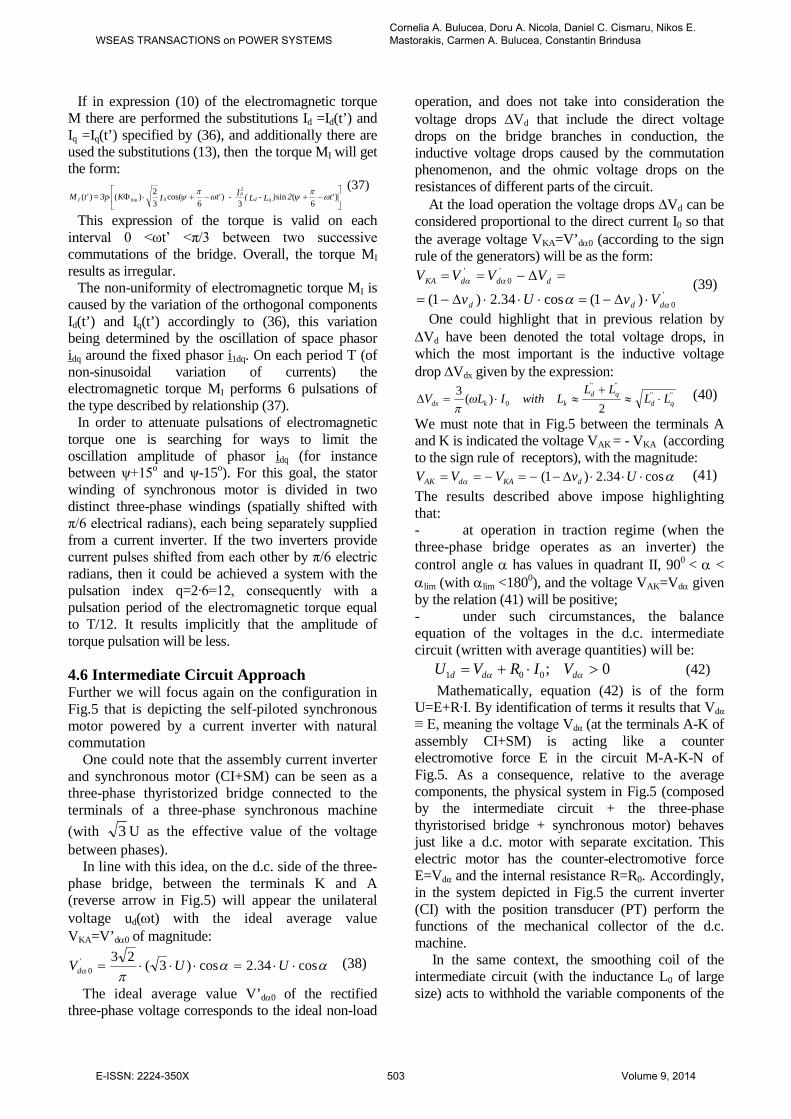
If in expression (10) of the electromagnetic torque M there are performed the substitutions Id =Id(t’) and Iq =Iq(t’) specified by (36), and additionally there are used the substitutions (13), then the torque MI will get the form:
úû
ùêë
é-+-+×F× )'
6(sin
3)'
6cos(
32)()'( 0 t2)L - L(I - tIK3p = tM qd
20
0mI wpywpy (37)
This expression of the torque is valid on each interval 0 <ωt’ <π/3 between two successive commutations of the bridge. Overall, the torque MI results as irregular.
The non-uniformity of electromagnetic torque MI is caused by the variation of the orthogonal components Id(t’) and Iq(t’) accordingly to (36), this variation being determined by the oscillation of space phasor idq around the fixed phasor i1dq. On each period T (of non-sinusoidal variation of currents) the electromagnetic torque MI performs 6 pulsations of the type described by relationship (37).
In order to attenuate pulsations of electromagnetic torque one is searching for ways to limit the oscillation amplitude of phasor idq (for instance between ψ+15o and ψ-15o). For this goal, the stator winding of synchronous motor is divided in two distinct three-phase windings (spatially shifted with π/6 electrical radians), each being separately supplied from a current inverter. If the two inverters provide current pulses shifted from each other by π/6 electric radians, then it could be achieved a system with the pulsation index q=2·6=12, consequently with a pulsation period of the electromagnetic torque equal to T/12. It results implicitly that the amplitude of torque pulsation will be less.
4.6 Intermediate Circuit Approach Further we will focus again on the configuration in Fig.5 that is depicting the self-piloted synchronous motor powered by a current inverter with natural commutation One could note that the assembly current inverter and synchronous motor (CI+SM) can be seen as a three-phase thyristorized bridge connected to the terminals of a three-phase synchronous machine (with 3 U as the effective value of the voltage between phases). In line with this idea, on the d.c. side of the three-phase bridge, between the terminals K and A (reverse arrow in Fig.5) will appear the unilateral voltage ud(wt) with the ideal average value VKA=V’da0 of magnitude:
aapa cos34.2cos)3(23'
0 ××=×××= UUVd (38)
The ideal average value V’da0 of the rectified three-phase voltage corresponds to the ideal non-load
operation, and does not take into consideration the voltage drops DVd that include the direct voltage drops on the bridge branches in conduction, the inductive voltage drops caused by the commutation phenomenon, and the ohmic voltage drops on the resistances of different parts of the circuit. At the load operation the voltage drops DVd can be considered proportional to the direct current I0 so that the average voltage VKA=V’da0 (according to the sign rule of the generators) will be as the form:
'0
'0
'
)1(cos34.2)1( a
aa
a ddd
dddKA
VvUv
VVVV
×D-=×××D-=
=D-== (39)
One could highlight that in previous relation by DVd have been denoted the total voltage drops, in which the most important is the inductive voltage drop DVdx given by the expression:
''''''''
0 2)(3
qdqd
kkdx LLLL
LwithILV ×»+
»×=D wp
(40)
We must note that in Fig.5 between the terminals A and K is indicated the voltage VAK = - VKA (according to the sign rule of receptors), with the magnitude:
aa cos34.2)1( ×××D--=-== UvVVV dKAdAK (41) The results described above impose highlighting that: - at operation in traction regime (when the three-phase bridge operates as an inverter) the control angle a has values in quadrant II, 900 < a < alim (with alim <1800), and the voltage VAK=Vda given by the relation (41) will be positive; - under such circumstances, the balance equation of the voltages in the d.c. intermediate circuit (written with average quantities) will be: 0;001 >×+= aa ddd VIRVU (42) Mathematically, equation (42) is of the form U=E+R·I. By identification of terms it results that Vdα ≡ E, meaning the voltage Vdα (at the terminals A-K of assembly CI+SM) is acting like a counter electromotive force E in the circuit M-A-K-N of Fig.5. As a consequence, relative to the average components, the physical system in Fig.5 (composed by the intermediate circuit + the three-phase thyristorised bridge + synchronous motor) behaves just like a d.c. motor with separate excitation. This electric motor has the counter-electromotive force E=Vdα and the internal resistance R=R0. Accordingly, in the system depicted in Fig.5 the current inverter (CI) with the position transducer (PT) perform the functions of the mechanical collector of the d.c. machine. In the same context, the smoothing coil of the intermediate circuit (with the inductance L0 of large size) acts to withhold the variable components of the
WSEAS TRANSACTIONS on POWER SYSTEMSCornelia A. Bulucea, Doru A. Nicola, Daniel C. Cismaru, Nikos E. Mastorakis, Carmen A. Bulucea, Constantin Brindusa
E-ISSN: 2224-350X 503 Volume 9, 2014

supply voltage of the system in Fig.5, so that to the terminals M-N to remain solely the direct voltage U1d. The purpose of the intermediate circuit powering consists in maintaining the constant magnitude of the direct current (I0=ct.) at any value of the running speed. To this effect, the supply voltage U1d of the intermediate circuit must be adjusted depending on the speed, according to the law U1d=f(v), which is graphically represented in Fig.9 by the diagram a-b-c-d. This diagram is built on the basis of relations (42), (41) and the variation law of the synchronous motor phase voltage U=U(Ω).
Actually, at v=0 the voltage U1d has the minimum value R0·I0 , then it must be linearly increased with the speed according to the straight line a-b-c. At the rated speed vN the intermediate circuit supply voltage will reach the maximum U1d=UC=U1dmax. The subsequent increase of speed (at I0=ct.) might be obtained solely by the weakening of main flux of synchronous motor Φ0= Φ0(IE). One could note that this weakening is obtained along with the decrease of excitation current IE, while the intermediate circuit remains powered at maximum voltage U1d=U1dmax=ct. One could highlight some explanatory notes. The first ascertainment emphasizes that, in case of electric railway vehicles powered from a single-phase industrial frequency a.c. contact line, the network converter is composed of two single-phase rectifier bridges (a fully controlled bridge and a bridge half-controlled) connected in series and sequentially controlled in terms of speed, as below: - at very low speeds 0<v≤vm (see Fig.9) the intermediate circuit is powered by the fully controlled rectifier bridge, and the current inverter (CI) will have assisted commutation; - at low speeds (over vm) when vm<v≤vb (see Fig.9) the current inverter is passing in operation with natural commutation. The thyristorised rectifier bridge begins to function as a mix bridge (in order to improve the power factor) and will be controlled to
increase the voltage U1d up to b1b=Ub=0.5·U1dmax at the speed vb. At the speed vb (equal to 0.5·vN) the thyristorised rectifier bridge will be fully open; - at speeds in the range vb<v≤vN occurs mixed rectifier bridge which (connected in series with the fully controlled bridge) will increase the voltage U1d from the value Ub to the maximum U1dmax (at the speed vN); - at higher speeds vN<v≤vM, the two rectifier bridges connected in series, fully opened, are powering the intermediate circuit with the voltage U1d=U1dmax=ct. The second statement focuses on the electric braking regime. The overexcited synchronous machine will operate as autonomous synchronous generator, and the three phase bridge CI (at the same current direction through the thyristors) will now operate as controlled three phase rectifier with α≈0 (meaning, nearly to a three-phase diode bridge). The voltage VAK=Vdα<0 (results negative for α≈0) so that the electric power PAK (changed through the terminals A and K) and calculated with: 0IVP 0dAK <×= a (43) will be negative. That power will be provided to the intermediate circuit in which it should be consumed by dissipation on the braking resistances RF. Moreover, one could note that operation in electric braking regime of the self-piloted synchronous machine is completely independent of the presence of contact line voltage, which ensures an efficiency of 100%. 5 Conclusion The sustainability dynamics in operation of electric railway vehicles has been addressed, highlighting the chain of interactions within the main electric equipment on an electrically driven railway system supplied from a d.c. or an a.c. contact line: the contact line–side converter, the machine–side converter and the traction synchronous motor.
The paper supports the findings that electric traction drive systems using synchronous motors fed by current inverters enhance the sustainable operation of railway trains. Electric traction drive systems using synchronous motors fed by current inverters provide high performance for high speed electric trains, in terms of both train dynamics and environmental issues, while advanced power current inverters ensure optimum traction and minimum energy use. Hence, the paper highlights that in order to synchronize the machine rotating field with the rotor (and avoiding the risk of losing the synchronism at any frequency value of stator currents) the synchronous motor will control the
Fig.9 Diagrams U1d=f(v) and I0=f(v) of intermediate circuit
WSEAS TRANSACTIONS on POWER SYSTEMSCornelia A. Bulucea, Doru A. Nicola, Daniel C. Cismaru, Nikos E. Mastorakis, Carmen A. Bulucea, Constantin Brindusa
E-ISSN: 2224-350X 504 Volume 9, 2014
current inverter which is powering it, becoming this way a self-piloted synchronous motor. Actually, the position of direct axis of synchronous motor rotor will be evolutionary checked in time (through the position transducers) by 6·p times during each complete rotation (at any value of rotor speed), by the ignition control of the thyristor of the current inverter bridge that is supplying the motor.
The physical phenomena within the electric system composed by the contact line-side converter, the machine-side converter and the traction synchronous motor are complex and its overall behaviour suggests that cleaner production offers an appropriate framework for assessing the sustainability of an electric railway system. Hence, the paper emphasizes that at electrically driven railway systems with traction synchronous motors the functions of amplitude adjustment are completely separate from those of the frequency control. As sequel, the result is a simpler construction for both the power part and the control electronics of static converters. References:
[1] Nicola, D.A.; Rosen, M.A. Bulucea, C.A.;
Brandusa, C. Sustainable Energy Conversion in Electrically Driven Transportation Systems, Proc. 6th WSEAS Int. Conf. on Engineering Education (EE’09), Rhodes, Greece, July 22-24, 2009, pp. 124-132.
[2] Nicola, D.A.; Rosen, M.A.; Bulucea, C.A.; Brandusa, C. Some Sustainability Aspects of Energy Conversion in Urban Electric Trains, Sustainability, 2010, 2, 1389-1407.
[3] Bulucea, C.A.; Nicola, D.A.; Cismaru, D.C.; Mastorakis, N.E.; Bulucea, C.A.; Brindusa, C. Embedding sustainability dynamics in energy conversion chain on electric railway vehicles with traction synchronous motors. Advances in Environmental Sciences, Development and Chemistry, Proc.of the 2014 Int. Conf. on Energy, Environment, Development and Economics (EEDS 2014), Santorini Island, Greece, July 17-21, 2014, pp.21-28
[4] Bulucea, C.A.; Nicola, D.A.; Mastorakis, N.E.; Rosen, M.A. Understanding Electric Industrial Ecosystems through Exergy, Recent Researches in Energy and Environment: Proc. 6th IASME/WSEAS Int. Conf. on Energy and Environment, Cambridge, UK, February 20-25, 2011, pp. 182-191.
[5] Nicola, D.A.; Bulucea, C.A.; Cismaru, D.C.; Brandusa, C. Energy Saving in Electric Trains
with Traction Induction Motors, Proc. 4th IASME/WSEAS Int. Conf. on Energy & Environment, Cambridge, UK, Feb. 24-26, 2009, pp. 226-232.
[6] Nicola, D.A.; Rosen, M.A.; Bulucea, C.A.; Cismaru, D.C. Some Aspects of Sustainable Energy Conversion in Electric Railway Vehicles with Traction Induction Motors, Recent Advances in Systems Science: Proc. 17th Int. Conf. on Systems, Rhodes Island, Greece, July 16-19, 2013, pp. 44-53.
[7] INTRODUCTION TO CLEANER PRODUCTION (CP) CONCEPTS AND PRACTICE, Prepared by the Institute of Environmental Engineering (APINI) Kaunas University of Technology, Lithuania, Sponsored by UNEP, Division of Technology, Industry, and Economics , Available at: http://www.un.org/esa/sustdev/sdissues/technology/cleanerproduction.pdf , accessed on 15 December, 2013.
[8] United Nations , The future we want, United nations Conference on Sustainable Development, Rio de Janeiro, Brazil, 20-22 June 2012, Available at: http://www.unep.fr/scp/pdf/Rio_The_Future_We_Want.pdf, accessed on 10 December, 2013
[9] Nicola, D.A.; Cismaru, D.C. Tractiune Electrica: Fenomene, Modele, Solutii (Electric Traction: Phenomena, Models, Solutions), SITECH Publishing House, Craiova, Romania, 2006.
[10] Cismaru, D.C.; Nicola, D.A.; Manolea, G. Locomotive electrice. Rame si trenuri electrice. Probleme specifice la viteze mari. Arhitecturi electrice. Modele si scheme structurale. Control computerizat (Electric Locomotives. Electric Multiple Units and Electric Trains. Specific Problems at High Speed. Electrical Architecture. Models and Structural Diagrams. Computer Control), SITECH Publishing House, Craiova, Romania, 2009.
[11] Nicola, D.A. Tractiune electrica (Electric Traction), Universitaria Publishing House, Craiova, Romania, 2012.
[12] Kaller, R.; Allenbach, J.N. Traction Electrique (Electrical Traction), Vol. 1-2, PPUR, Lausanne, 1995.
[13] Perticaroli, F. Sistemi elettrici per i transporti: Trazione elettrica (Electrical Systems for Transp[ortation: Electric Traction). Ed. Masson, Milano-Parigi-Barcellona, 1994.
[14] Steimel, A. Electric Traction. Motion Power and Energy Supply Basics and Practical
WSEAS TRANSACTIONS on POWER SYSTEMSCornelia A. Bulucea, Doru A. Nicola, Daniel C. Cismaru, Nikos E. Mastorakis, Carmen A. Bulucea, Constantin Brindusa
E-ISSN: 2224-350X 505 Volume 9, 2014

Experience, Oldenbourg Industrieverlag, München, 2008.
[15] Georgescu, M. Tracţiunea electrică de mare viteză cu motoare sincrone (High Speed Electric Traction with Synchronous Motors), Publishing House Dacia, Cluj-Napoca, 2001.
[16] Chatelain, J. Machines électriques (Electrical Machines), PPUR, Lausanne, 1989.
[17] Bakshi, U.A.; Bakshi, M.V. Electrical Drives and Controls, Technical Publications Pune, First Edition, 2009, Available at: http://books.google.ro/books?id=RXRO2nTaDz4C&printsec=frontcover&dq=electrical++drives&hl=en&ei=-swoToC-AfCmsQK3kuGfCw&sa=X&oi=book_result&ct=result&redir_esc=y#v=onepage&q&f=false, accessed on December 25, 2013
[18] Buhler, H. Reglage de Systemes d’Electronique de Puissance, Vol. I, PPUR, Lausanne, 1997.
[19] Carpita, M.; Monti, A. Voltage Source Converters and Drives Simulation at System Level for Control Design Applications, EPE Journal, Vol. 5, No. 3/4, 1996, pp. 49-55.
[20] Muntean, N. Convertoare statice (Static Converters), Publishing House Politehnica, Timişoara, 1998.
[21] Nicola, D.A.; Bulucea, C.A. Electrotehnica, masini si echipamente electrice (Electrotechnics, Electrical Machines and Equipment), SITECH Publishing House, Craiova, Romania, 2005.
WSEAS TRANSACTIONS on POWER SYSTEMSCornelia A. Bulucea, Doru A. Nicola, Daniel C. Cismaru, Nikos E. Mastorakis, Carmen A. Bulucea, Constantin Brindusa
E-ISSN: 2224-350X 506 Volume 9, 2014