guideline on earthing and bonding at railway stations · earthing and bonding. the implications for...
TRANSCRIPT
Prepared by : M. Logan
Engineering Standards & Services,Electrical
11th Floor, Sydney Central Building477 Pitt St, Sydney 2000Phone: (02) 9782 1130Fax: (02) 9782 [email protected] gov.au
Client : Julian RichardsManager, Buildings
Guideline - Station Earthing & Bonding
October, 2004
GUIDELINE ON EARTHING ANDBONDING AT RAILWAY STATIONS
Reconfirmed 10 July 2019
Guideline on Earthing and Bonding
Page 2 of 31
Table of contents
1. Purpose _______________________________________________________________ 32. Scope _________________________________________________________________ 33. Introduction ____________________________________________________________ 44. Effects of DC Stray Current _______________________________________________ 55. Earthing and Bonding Issues ______________________________________________ 6
5.1 Bonding ___________________________________________________________________ 6
5.2 Earthing __________________________________________________________________ 10
5.3 Separation issues ___________________________________________________________ 12
5.4 Isolation issues _____________________________________________________________ 20
6. Conclusion ____________________________________________________________ 26APPENDIX 1 _____________________________________________________________ 28
Guideline on Earthing and Bonding
Page 3 of 31
1. Purpose
The purpose of this document is to promote an awareness of earthing andbonding issues prevalent at railway stations. This document has beenproduced for internal RailCorp use only. It is particularly targeted for non-electrical persons such as project managers, asset engineers, external partyworks, etc carrying out either construction or maintenance work at railwaystations.
This document is not intended to be included in any technical brief fortendering purposes and is not a substitute for appropriate engineeringdesign guidelines.
2. Scope
The overall scope for this guideline targets railway stations within theRailCorp 1500 volt direct current electrified traction system.
Specifically, the contents of this document relate to the interface of thetraction 1500V DC traction system, high voltage reticulation system and lowvoltage distribution systems. Electrical hazardous situations may exist atrailway stations due to these interfaces, resulting in issues relating toearthing and bonding.
The implications for not addressing risk management strategies relating toearthing and bonding issues has ramifications on safety and infrastructureintegrity, including economic and operational impact.
The outcomes of this guideline are as follows:
• promote an awareness of earthing and bonding issues prevalent atrailway stations and to educate persons responsible for eitherconstruction or maintenance work at railway stations.
• reduce to a level as low as reasonably practicable the risk of injuryfrom electric shock from accessible and touch voltages.
• reduce to a level as low as reasonably practicable the export ofstray current from DC traction systems.
Guideline on Earthing and Bonding
Page 4 of 31
3. Introduction
RailCorp needs to safeguard itself against risk of damage, fire, electric shockor loss of life due to risks from faults etc., associated with its 1500V DCtraction system, high voltage reticulation system and low voltage distributionsystems.
At railway stations, three main types of risks may exist:
1. Risks associated with 1500V DC stray leakage or fault current.
2. Electric shock risk due to 1500V DC touch & step potential rise underfault condition, in particular with regard to remote earths in accordancewith EP 00000008SP.
3. Electric shock risk due to high voltage/low voltage distribution systems’touch & step potential rise under fault condition, in particular with regardto different earthing systems.
With the proliferation of railway station upgrading work and associatedconstruction of station canopies, the incidence of electrical hazardoussituations has increased. The majority of these situations relate to issues ofearthing and bonding.
There is a possibility that overhead wiring structures may rise to a potentialabove earth. The risk of persons receiving an electric shock when standingbeside an overhead wiring structure and touching the structure is presentand is of concern. Other hazardous situations where persons could receivean electric shock is when physical contact is made by touching overheadwiring structures at the same time as they touch lighting poles, metallic partsof canopies or awnings, steel troughing, metal fences or rolling stock.
In order to minimise these risks, methods have been developed anddeployed for the overhead wiring system which are detailed in RICstandards. Selected extracts from relevant RIC documents dealing withrailway station earthing and bonding requirements are in Appendix 1.
One of the more common control measures used at stations is to separateoverhead wiring structures by distance from any other components on thestation. However, station upgrading work has often compromised thiscontrol, along with other earthing and bonding issues.
Guideline on Earthing and Bonding
Page 5 of 31
4. Effects of DC Stray Current
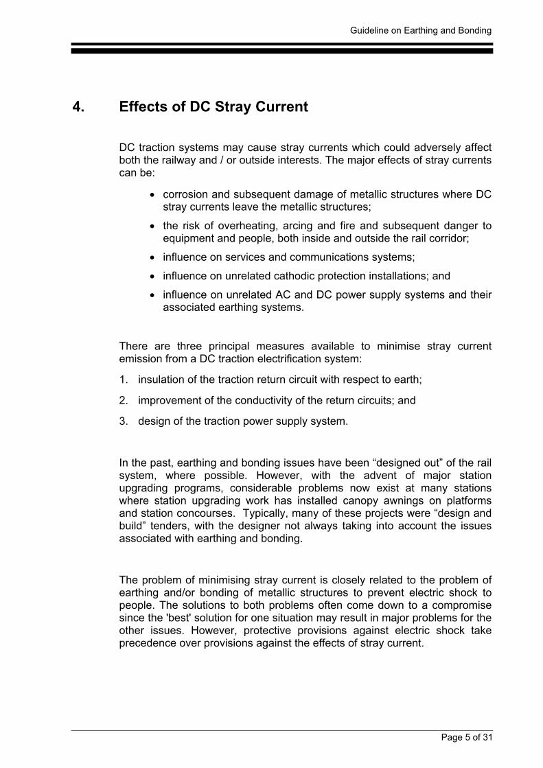
DC traction systems may cause stray currents which could adversely affectboth the railway and / or outside interests. The major effects of stray currentscan be:
• corrosion and subsequent damage of metallic structures where DCstray currents leave the metallic structures;
• the risk of overheating, arcing and fire and subsequent danger toequipment and people, both inside and outside the rail corridor;
• influence on services and communications systems;
• influence on unrelated cathodic protection installations; and
• influence on unrelated AC and DC power supply systems and theirassociated earthing systems.
There are three principal measures available to minimise stray currentemission from a DC traction electrification system:
1. insulation of the traction return circuit with respect to earth;
2. improvement of the conductivity of the return circuits; and
3. design of the traction power supply system.
In the past, earthing and bonding issues have been “designed out” of the railsystem, where possible. However, with the advent of major stationupgrading programs, considerable problems now exist at many stationswhere station upgrading work has installed canopy awnings on platformsand station concourses. Typically, many of these projects were “design andbuild” tenders, with the designer not always taking into account the issuesassociated with earthing and bonding.
The problem of minimising stray current is closely related to the problem ofearthing and/or bonding of metallic structures to prevent electric shock topeople. The solutions to both problems often come down to a compromisesince the 'best' solution for one situation may result in major problems for theother issues. However, protective provisions against electric shock takeprecedence over provisions against the effects of stray current.
Guideline on Earthing and Bonding
Page 6 of 31
5. Earthing and Bonding Issues
Earthing and Bonding Issues may be categorised into the following sub-headings:
• 1500 Volt Bonding
• Earthing
• Separation issues
• Isolation issues
More often than not, earthing and/or bonding issues are inter-related andmay involve one or more, or a combination of the sub-headings.
Many earthing and bonding strategies are conditional upon the particularconfiguration of the station and the earthing and bonding philosophy adoptedfor each unique situation. In some instances, especially at larger complexstations, the separation issues may become too complex and too difficult toadequately control and monitor.
In these situations, one option is to interconnect all metallic structures etc. toovercome possible touch potential problems, thus negating the separationissues. However, there are also negative trade-offs with this option.
As previously stated, the resultant solution to many earthing and bondingissues often come down to a compromise solution. This especially applies toconfigurations where these issues have not been adequately addressed inthe design stages.
The following headings give a background on the outstanding issues relatingto each category. Descriptions, and in some cases photos, are given in eachcase to clarify “poor” design configurations as opposed to “good” designconfigurations.
5.1 Bonding
Examples of bonding issues are, but are not limited to:
• bonding of steel/metal footbridges (OHW attached)
• bonding of overline traffic bridges (OHW attached)
• bonding of 1500 V structures in vicinity of station as per standards
• bonding of safety screens as per standards
Guideline on Earthing and Bonding
Page 7 of 31
A number of possible bonding arrangements exist for railway stations,depending on the configuration and physical arrangement of overhead wiringsupports, the station premises and canopy design.
The bonding arrangements for stations, station bridges and overline trafficbridges are covered in documents EP 12 20 00 01 SP “Bonding of OverheadWiring Structures to Rail” and EP 08 00 00 07 SP “Safety Screens forBridges over 1500 V OHW Equipment”
There is a possibility that overhead wiring structures may rise to a potentialabove earth. The risk of persons receiving an electric shock when standingbeside an overhead wiring structure and touching the structure is presentand is of concern. Other hazardous situations where persons could receivean electric shock is when physical contact is made by touching overheadwiring structures at the same time as they touch lighting poles, metallic partsof canopies or awnings, steel troughing, metal fences or rolling stock.
In order to minimise this risk, methods have been developed and deployedfor the overhead wiring system.
A number of selected OHW structures in the traction system are required tobe bonded to rail. The determination of the policy on which structures are tobe bonded has involved a risk assessment to identify the most likelylocations and situations giving greatest exposure to risk. As can be seenfrom the dot points below, station platforms pose the greatest threat of thisrisk exposure.
Overhead wiring (OHW) structures, and other structures that support 1500Voverhead wiring, at prescribed locations, must be bonded to a traction railvia a spark gap or similar device as detailed in EP 12 20 00 01 SP.
The overhead wiring structures at stations must be bonded to rail as per thefollowing:
• Where passengers and/or the public are likely to contact thestructure, including OHW structures at platforms and up to 10mbeyond the ends of the platforms.
• Where important structures might otherwise be exposedexcessively to corrosion (e.g. bridges).
Guideline on Earthing and Bonding
Page 8 of 31
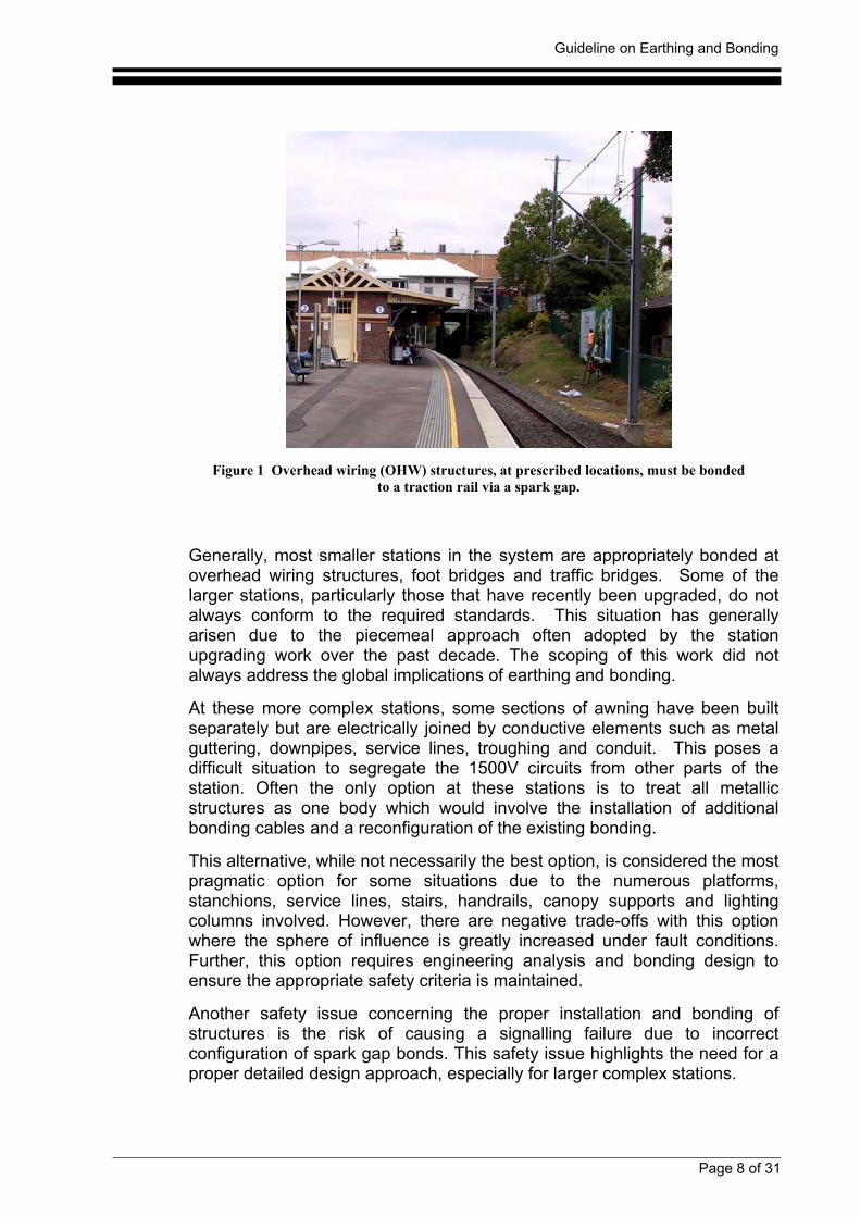
Figure 1 Overhead wiring (OHW) structures, at prescribed locations, must be bondedto a traction rail via a spark gap.
Generally, most smaller stations in the system are appropriately bonded atoverhead wiring structures, foot bridges and traffic bridges. Some of thelarger stations, particularly those that have recently been upgraded, do notalways conform to the required standards. This situation has generallyarisen due to the piecemeal approach often adopted by the stationupgrading work over the past decade. The scoping of this work did notalways address the global implications of earthing and bonding.
At these more complex stations, some sections of awning have been builtseparately but are electrically joined by conductive elements such as metalguttering, downpipes, service lines, troughing and conduit. This poses adifficult situation to segregate the 1500V circuits from other parts of thestation. Often the only option at these stations is to treat all metallicstructures as one body which would involve the installation of additionalbonding cables and a reconfiguration of the existing bonding.
This alternative, while not necessarily the best option, is considered the mostpragmatic option for some situations due to the numerous platforms,stanchions, service lines, stairs, handrails, canopy supports and lightingcolumns involved. However, there are negative trade-offs with this optionwhere the sphere of influence is greatly increased under fault conditions.Further, this option requires engineering analysis and bonding design toensure the appropriate safety criteria is maintained.
Another safety issue concerning the proper installation and bonding ofstructures is the risk of causing a signalling failure due to incorrectconfiguration of spark gap bonds. This safety issue highlights the need for aproper detailed design approach, especially for larger complex stations.
Guideline on Earthing and Bonding
Page 9 of 31
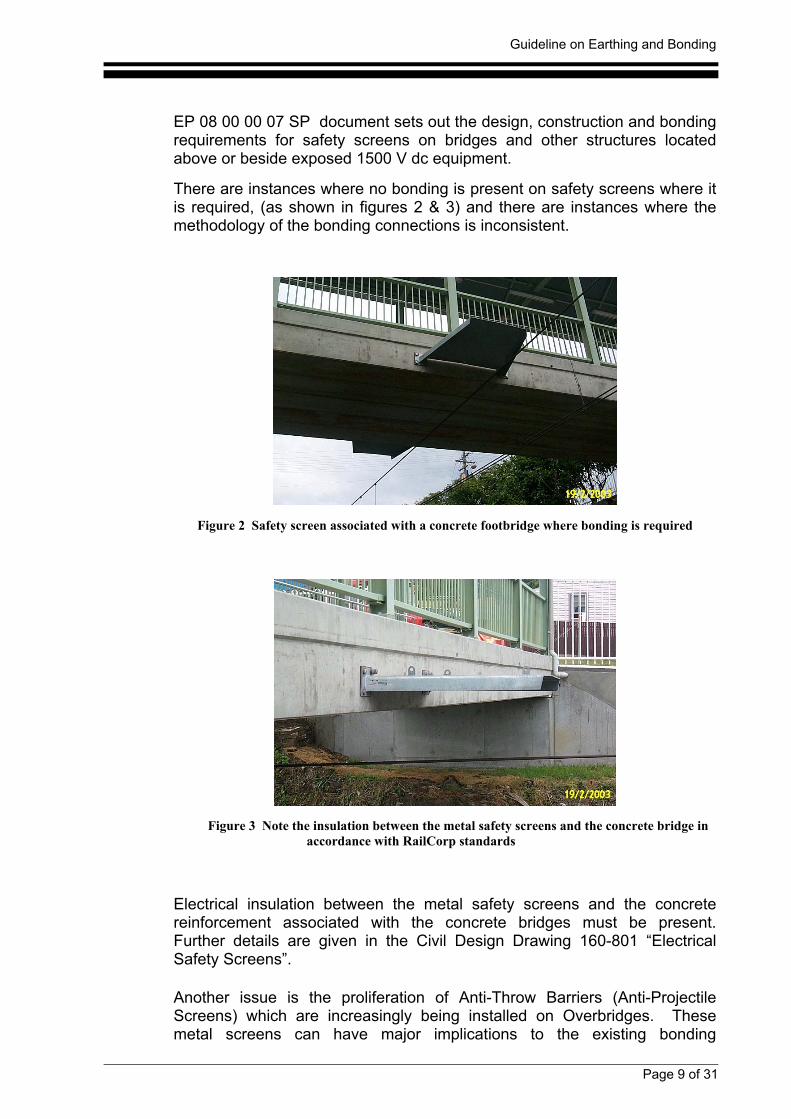
EP 08 00 00 07 SP document sets out the design, construction and bondingrequirements for safety screens on bridges and other structures locatedabove or beside exposed 1500 V dc equipment.
There are instances where no bonding is present on safety screens where itis required, (as shown in figures 2 & 3) and there are instances where themethodology of the bonding connections is inconsistent.
Figure 2 Safety screen associated with a concrete footbridge where bonding is required
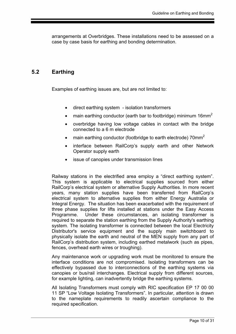
Figure 3 Note the insulation between the metal safety screens and the concrete bridge inaccordance with RailCorp standards
Electrical insulation between the metal safety screens and the concretereinforcement associated with the concrete bridges must be present.Further details are given in the Civil Design Drawing 160-801 “ElectricalSafety Screens”.
Another issue is the proliferation of Anti-Throw Barriers (Anti-ProjectileScreens) which are increasingly being installed on Overbridges. Thesemetal screens can have major implications to the existing bonding
Guideline on Earthing and Bonding
Page 10 of 31
arrangements at Overbridges. These installations need to be assessed on acase by case basis for earthing and bonding determination.
5.2 Earthing
Examples of earthing issues are, but are not limited to:
• direct earthing system - isolation transformers
• main earthing conductor (earth bar to footbridge) minimum 16mm2
• overbridge having low voltage cables in contact with the bridgeconnected to a 6 m electrode
• main earthing conductor (footbridge to earth electrode) 70mm2
• interface between RailCorp’s supply earth and other NetworkOperator supply earth
• issue of canopies under transmission lines
Railway stations in the electrified area employ a “direct earthing system”.This system is applicable to electrical supplies sourced from eitherRailCorp’s electrical system or alternative Supply Authorities. In more recentyears, many station supplies have been transferred from RailCorp’selectrical system to alternative supplies from either Energy Australia orIntegral Energy. The situation has been exacerbated with the requirement ofthree phase supplies for lifts installed at stations under the Easy AccessProgramme. Under these circumstances, an isolating transformer isrequired to separate the station earthing from the Supply Authority's earthingsystem. The isolating transformer is connected between the local ElectricityDistributor's service equipment and the supply main switchboard tophysically isolate the earth and neutral of the MEN supply from any part ofRailCorp’s distribution system, including earthed metalwork (such as pipes,fences, overhead earth wires or troughing).
Any maintenance work or upgrading work must be monitored to ensure theinterface conditions are not compromised. Isolating transformers can beeffectively bypassed due to interconnections of the earthing systems viacanopies or bus/rail interchanges. Electrical supply from different sources,for example lighting, can inadvertently bridge the earthing systems.
All Isolating Transformers must comply with RIC specification EP 17 00 0011 SP “Low Voltage Isolating Transformers”. In particular, attention is drawnto the nameplate requirements to readily ascertain compliance to therequired specification.
Guideline on Earthing and Bonding
Page 11 of 31
When loadings at stations are substantially increased, corresponding higherfault levels are present. The earthing systems at stations may requireupgrading in line with additional loadings. The assessment of the suitabilityand integrity of the existing earthing system must form part of any upgradingwork.
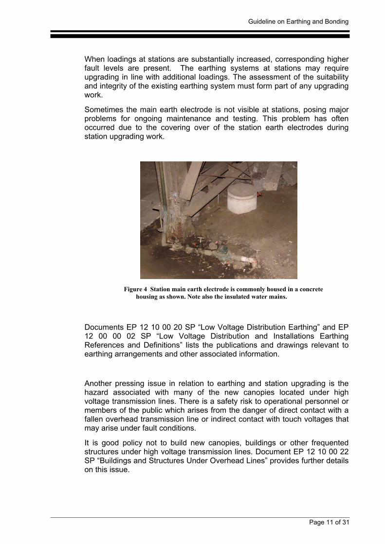
Sometimes the main earth electrode is not visible at stations, posing majorproblems for ongoing maintenance and testing. This problem has oftenoccurred due to the covering over of the station earth electrodes duringstation upgrading work.
Figure 4 Station main earth electrode is commonly housed in a concretehousing as shown. Note also the insulated water mains.
Documents EP 12 10 00 20 SP “Low Voltage Distribution Earthing” and EP12 00 00 02 SP “Low Voltage Distribution and Installations EarthingReferences and Definitions” lists the publications and drawings relevant toearthing arrangements and other associated information.
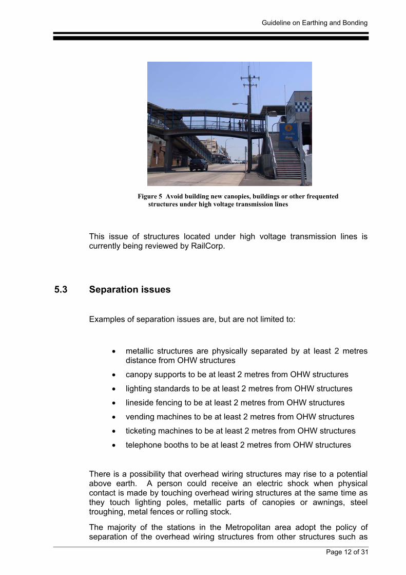
Another pressing issue in relation to earthing and station upgrading is thehazard associated with many of the new canopies located under highvoltage transmission lines. There is a safety risk to operational personnel ormembers of the public which arises from the danger of direct contact with afallen overhead transmission line or indirect contact with touch voltages thatmay arise under fault conditions.
It is good policy not to build new canopies, buildings or other frequentedstructures under high voltage transmission lines. Document EP 12 10 00 22SP “Buildings and Structures Under Overhead Lines” provides further detailson this issue.
Guideline on Earthing and Bonding
Page 12 of 31
Figure 5 Avoid building new canopies, buildings or other frequentedstructures under high voltage transmission lines
This issue of structures located under high voltage transmission lines iscurrently being reviewed by RailCorp.
5.3 Separation issues
Examples of separation issues are, but are not limited to:
• metallic structures are physically separated by at least 2 metresdistance from OHW structures
• canopy supports to be at least 2 metres from OHW structures
• lighting standards to be at least 2 metres from OHW structures
• lineside fencing to be at least 2 metres from OHW structures
• vending machines to be at least 2 metres from OHW structures
• ticketing machines to be at least 2 metres from OHW structures
• telephone booths to be at least 2 metres from OHW structures
There is a possibility that overhead wiring structures may rise to a potentialabove earth. A person could receive an electric shock when physicalcontact is made by touching overhead wiring structures at the same time asthey touch lighting poles, metallic parts of canopies or awnings, steeltroughing, metal fences or rolling stock.
The majority of the stations in the Metropolitan area adopt the policy ofseparation of the overhead wiring structures from other structures such as
Guideline on Earthing and Bonding
Page 13 of 31
roofs and buildings. Being in the vicinity of the general public, these OHWstructures are normally spark gapped to rail in accordance with RIC policydocument EP 12 20 00 01 SP “Bonding of Overhead Wiring Structures toRail”. In doing so, any operation of the spark gap results in the structurebeing directly connected to rail with the resultant structure having a voltagepresent corresponding to the rail voltage. The rail voltage level is dependentupon many factors such as location, distance from the substation, trainloadings and the characteristics of the rail and the overhead wiring. Undercertain circumstances, this voltage can rise to potentially dangerous levels.However, the upper voltage limits are overseen by the rail earth contactor atSubstation and Sectioning Huts.
Problems can exist on stations due to bonding arrangements of theoverhead wiring structures. The most common problems are proximity ofthe overhead wiring structures to:
1. metal fencing,
2. metallic awning supports,
3. earthed metallic objects such as lighting standards, vendingmachines, water pipes, telephone booths, fire hydrant apparatus andCCTV's.
For situations where any of the separation criteria cannot be achieved,alternative options may be implemented to negate the separation issue.
Briefly, the possible alternative arrangements are:
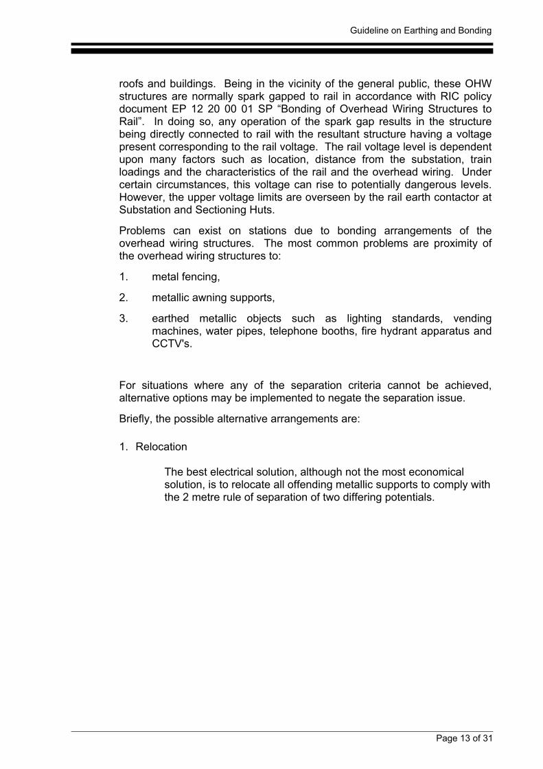
1. Relocation
The best electrical solution, although not the most economicalsolution, is to relocate all offending metallic supports to comply withthe 2 metre rule of separation of two differing potentials.
Guideline on Earthing and Bonding
Page 14 of 31
Figure 6 Option 1 - Metallic supportsto comply with the 2 metre rule ofseparation from OHW structure.
Figure 7 Option 4 - OHW structure isolationwhere the OHW stucture is enclosed byinsulation material.
2. Limited Isolation
This option attempts to limit the physical extent of conductivematerial which could be exposed to 1500 V fault current bysegregation using appropriate insulated sections to ensureelectrical discontinuity.This option has significant maintenance issues.
3. Interconnected metal mass.
This option attempts to overcome possible touch potential problemsby ensuring all metallic structures are electrically connected.However, this option can have negative trade-offs. 1500V faultcurrent will have a wider area of influence and the resulting faultcurrent path will be difficult to predict and manage.
4. OHW structure isolation
This option uses the concept of double insulation to effectivelyisolate an OHW structure section from the remaining sections ofthe structure.This option has significant cost impacts as well as ongoingmaintenance and surveillance issues.
The best option which overcomes the majority of earthing and bondingissues is option 1, which uses the principle of separation. Obviously, ininstallations where this separation is compromised, it can be an expensiveexercise to either relocate all offending metallic supports or revert to otheralternatives.
Guideline on Earthing and Bonding
Page 15 of 31
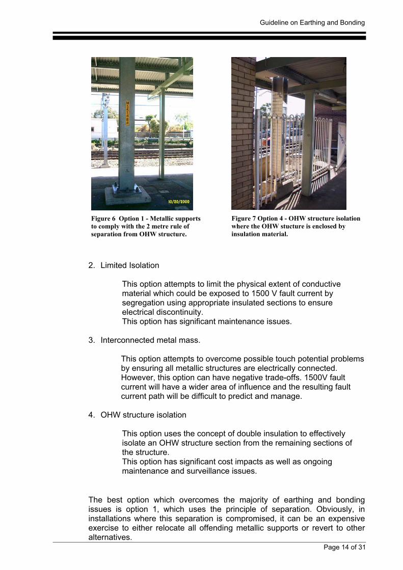
It is stressed that the most cost effective and safest configuration for anynew canopy or building work is to incorporate the principle of separation intothe design stage. If earthing and bonding issues are integrated into thedesign stage, substantial cost savings can be achieved as well as drasticallyreducing the risk exposure to persons and property.
This process of “designing out” earthing and bonding issues must be anessential outcome for RailCorp to safeguard itself against risk of damage,fire, electric shock or loss of life.
Figure 8 Example of poor design where the new canopy supports are in close proximity tothe existing OHW structure.
Many stations suffer from the problem of close proximity of overhead wiringstructures to fencing. The typical fencing encountered on many stations isthe powder coated pool style fencing which can run along either a section ofthe station platform or the total length of the platform.
Guideline on Earthing and Bonding
Page 16 of 31
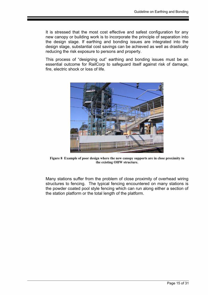
Figure 9 Close proximity of fencing andlighting standard to the overhead wiringstructure. Note the CCTV metalconduit at bottom of fence bridging anyisolation gaps if present.
Figure 10 Correctly installed fencing with twoseparate isolation gaps placed at least two metres oneither side of the OHW structure.
On some stations, the fencing has been properly installed by creating twoseparate isolation gaps placed at least two metres on either side of the OHWstructure as shown in Figure 10. However, there are many instances wherecontractors have bridged these gaps with metal conduit, usually used in theinstallation of extra lighting, water pipes or CCTV's. The appropriate remedyfor such situations is the replacement of the metal component across thegap with a non-conducting enclosure with suitable mechanical protection.
Considerable problems exist at many stations where station upgrading workhas installed canopy awnings on platforms and station concourses.Typically, many of these projects were design and build tenders, with thedesigner not always taking into account the separation issues associatedwith earthing and bonding. Consequently, large amounts of contingencywork have been required over the last few years to correct many of theproblems at stations. The most common problem is the close proximity ofmetallic awning supports relative to overhead wiring structures wheremetallic awning supports are within the two metre separation distances.
Guideline on Earthing and Bonding
Page 17 of 31
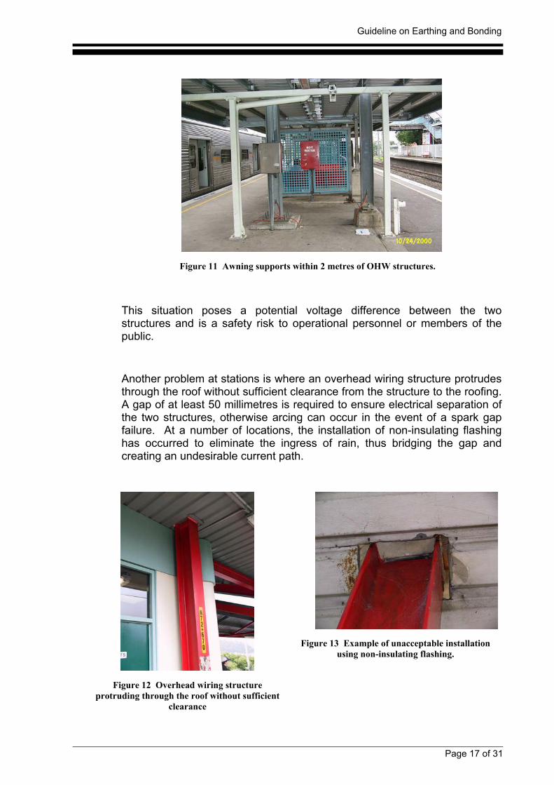
Figure 11 Awning supports within 2 metres of OHW structures.
This situation poses a potential voltage difference between the twostructures and is a safety risk to operational personnel or members of thepublic.
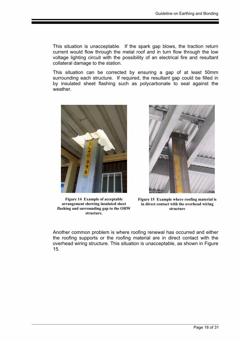
Another problem at stations is where an overhead wiring structure protrudesthrough the roof without sufficient clearance from the structure to the roofing.A gap of at least 50 millimetres is required to ensure electrical separation ofthe two structures, otherwise arcing can occur in the event of a spark gapfailure. At a number of locations, the installation of non-insulating flashinghas occurred to eliminate the ingress of rain, thus bridging the gap andcreating an undesirable current path.
Figure 12 Overhead wiring structureprotruding through the roof without sufficient
clearance
Figure 13 Example of unacceptable installationusing non-insulating flashing.
Guideline on Earthing and Bonding
Page 18 of 31
This situation is unacceptable. If the spark gap blows, the traction returncurrent would flow through the metal roof and in turn flow through the lowvoltage lighting circuit with the possibility of an electrical fire and resultantcollateral damage to the station.
This situation can be corrected by ensuring a gap of at least 50mmsurrounding each structure. If required, the resultant gap could be filled inby insulated sheet flashing such as polycarbonate to seal against theweather.
Figure 14 Example of acceptablearrangement showing insulated sheet
flashing and surrounding gap to the OHWstructure.
Figure 15 Example where roofing material isin direct contact with the overhead wiring
structure
Another common problem is where roofing renewal has occurred and eitherthe roofing supports or the roofing material are in direct contact with theoverhead wiring structure. This situation is unacceptable, as shown in Figure15.
Guideline on Earthing and Bonding
Page 19 of 31
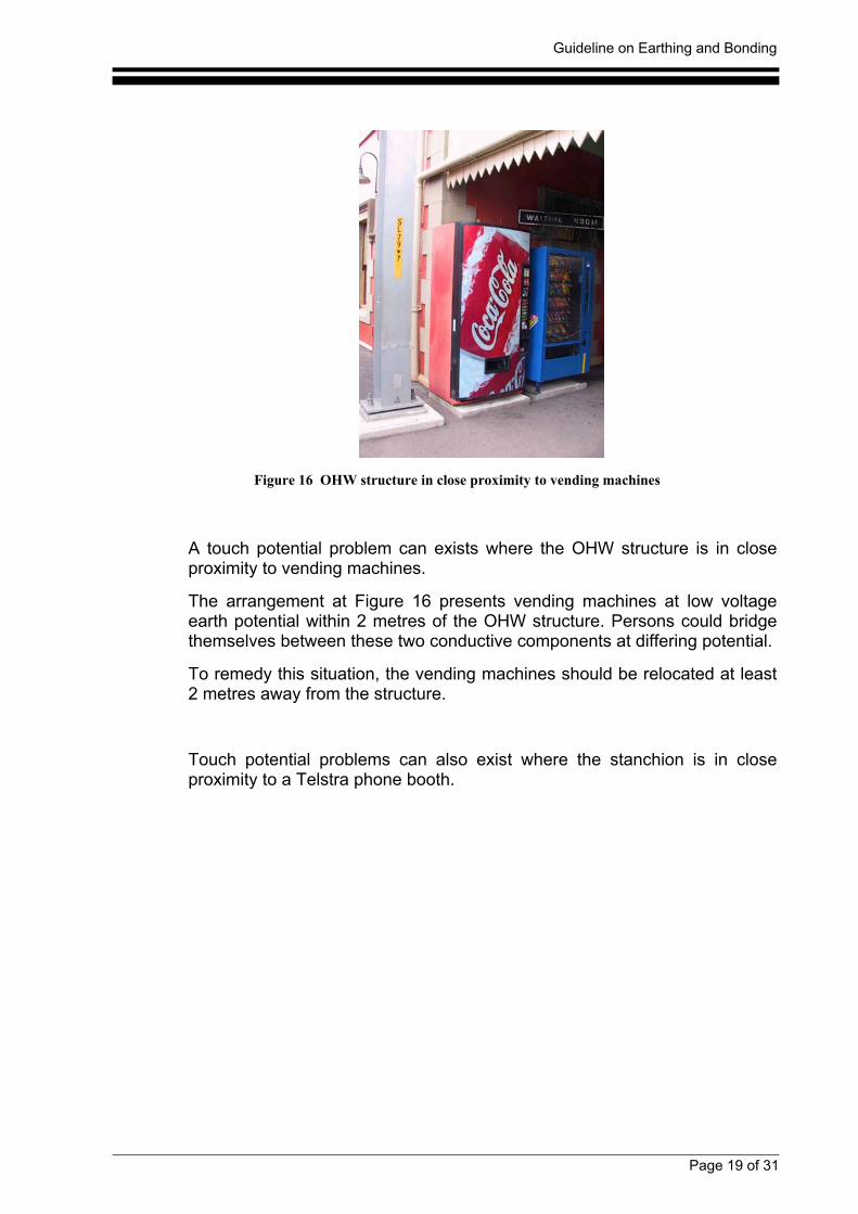
Figure 16 OHW structure in close proximity to vending machines
A touch potential problem can exists where the OHW structure is in closeproximity to vending machines.
The arrangement at Figure 16 presents vending machines at low voltageearth potential within 2 metres of the OHW structure. Persons could bridgethemselves between these two conductive components at differing potential.
To remedy this situation, the vending machines should be relocated at least2 metres away from the structure.
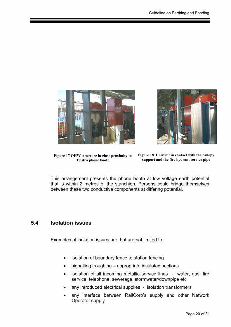
Touch potential problems can also exist where the stanchion is in closeproximity to a Telstra phone booth.
Guideline on Earthing and Bonding
Page 20 of 31
Figure 17 OHW structure in close proximity toTelstra phone booth
Figure 18 Unistrut in contact with the canopysupport and the fire hydrant service pipe
This arrangement presents the phone booth at low voltage earth potentialthat is within 2 metres of the stanchion. Persons could bridge themselvesbetween these two conductive components at differing potential.
5.4 Isolation issues
Examples of isolation issues are, but are not limited to:
• isolation of boundary fence to station fencing
• signalling troughing – appropriate insulated sections
• isolation of all incoming metallic service lines - water, gas, fireservice, telephone, sewerage, stormwater/downpipe etc
• any introduced electrical supplies - isolation transformers
• any interface between RailCorp’s supply and other NetworkOperator supply
Guideline on Earthing and Bonding
Page 21 of 31
• CCTV implications: metallic conduit runs, video cable connections
Document EP 12 10 00 21 SP “Low Voltage Installations Earthing” detailsthe earthing and bonding requirements of various types of low voltageinstallations located on the `railway corridor' and `near 1500 V track'.
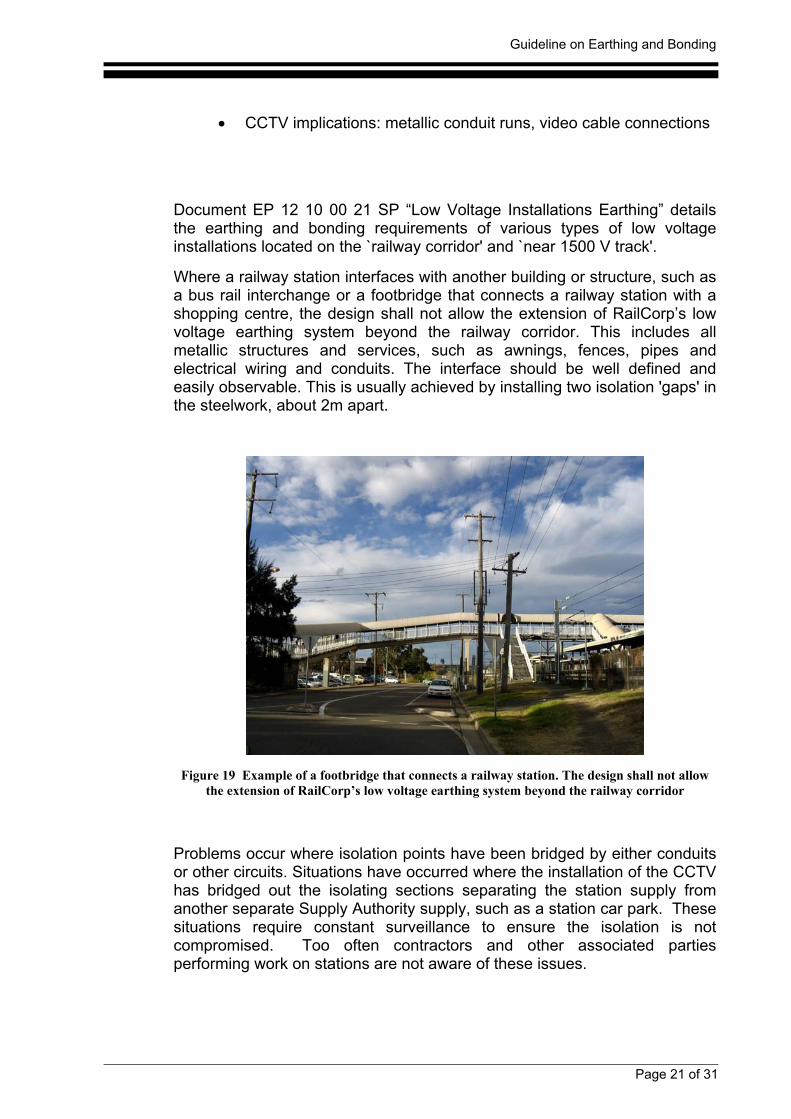
Where a railway station interfaces with another building or structure, such asa bus rail interchange or a footbridge that connects a railway station with ashopping centre, the design shall not allow the extension of RailCorp’s lowvoltage earthing system beyond the railway corridor. This includes allmetallic structures and services, such as awnings, fences, pipes andelectrical wiring and conduits. The interface should be well defined andeasily observable. This is usually achieved by installing two isolation 'gaps' inthe steelwork, about 2m apart.
Figure 19 Example of a footbridge that connects a railway station. The design shall not allowthe extension of RailCorp’s low voltage earthing system beyond the railway corridor
Problems occur where isolation points have been bridged by either conduitsor other circuits. Situations have occurred where the installation of the CCTVhas bridged out the isolating sections separating the station supply fromanother separate Supply Authority supply, such as a station car park. Thesesituations require constant surveillance to ensure the isolation is notcompromised. Too often contractors and other associated partiesperforming work on stations are not aware of these issues.
Guideline on Earthing and Bonding
Page 22 of 31
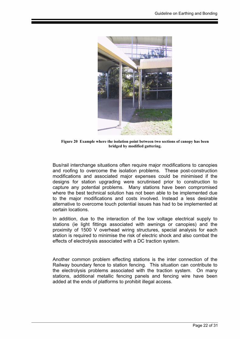
Figure 20 Example where the isolation point between two sections of canopy has beenbridged by modified guttering.
Bus/rail interchange situations often require major modifications to canopiesand roofing to overcome the isolation problems. These post-constructionmodifications and associated major expenses could be minimised if thedesigns for station upgrading were scrutinised prior to construction tocapture any potential problems. Many stations have been compromisedwhere the best technical solution has not been able to be implemented dueto the major modifications and costs involved. Instead a less desirablealternative to overcome touch potential issues has had to be implemented atcertain locations.
In addition, due to the interaction of the low voltage electrical supply tostations (ie light fittings associated with awnings or canopies) and theproximity of 1500 V overhead wiring structures, special analysis for eachstation is required to minimise the risk of electric shock and also combat theeffects of electrolysis associated with a DC traction system.
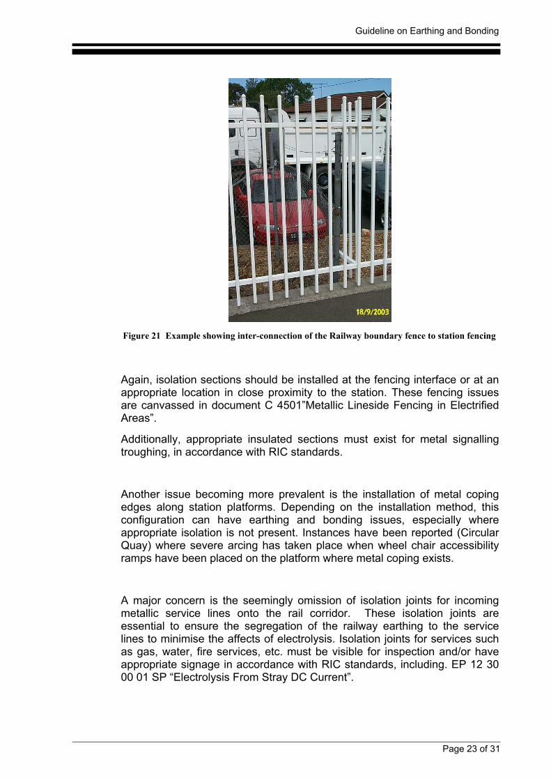
Another common problem effecting stations is the inter connection of theRailway boundary fence to station fencing. This situation can contribute tothe electrolysis problems associated with the traction system. On manystations, additional metallic fencing panels and fencing wire have beenadded at the ends of platforms to prohibit illegal access.
Guideline on Earthing and Bonding
Page 23 of 31
Figure 21 Example showing inter-connection of the Railway boundary fence to station fencing
Again, isolation sections should be installed at the fencing interface or at anappropriate location in close proximity to the station. These fencing issuesare canvassed in document C 4501”Metallic Lineside Fencing in ElectrifiedAreas”.
Additionally, appropriate insulated sections must exist for metal signallingtroughing, in accordance with RIC standards.
Another issue becoming more prevalent is the installation of metal copingedges along station platforms. Depending on the installation method, thisconfiguration can have earthing and bonding issues, especially whereappropriate isolation is not present. Instances have been reported (CircularQuay) where severe arcing has taken place when wheel chair accessibilityramps have been placed on the platform where metal coping exists.
A major concern is the seemingly omission of isolation joints for incomingmetallic service lines onto the rail corridor. These isolation joints areessential to ensure the segregation of the railway earthing to the servicelines to minimise the affects of electrolysis. Isolation joints for services suchas gas, water, fire services, etc. must be visible for inspection and/or haveappropriate signage in accordance with RIC standards, including. EP 12 3000 01 SP “Electrolysis From Stray DC Current”.
Guideline on Earthing and Bonding
Page 24 of 31
Figure 22 . Isolation joints for services such as gas, water, fire services, etc. must be visiblefor inspection and/or have appropriate signage.
Another major issue coming to the fore is the proliferation of CCTV camerason stations which has the potential to cause fire and collateral damage.
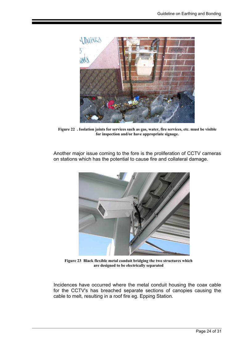
Figure 23 Black flexible metal conduit bridging the two structures whichare designed to be electrically separated
Incidences have occurred where the metal conduit housing the coax cablefor the CCTV's has breached separate sections of canopies causing thecable to melt, resulting in a roof fire eg. Epping Station.
Guideline on Earthing and Bonding
Page 25 of 31
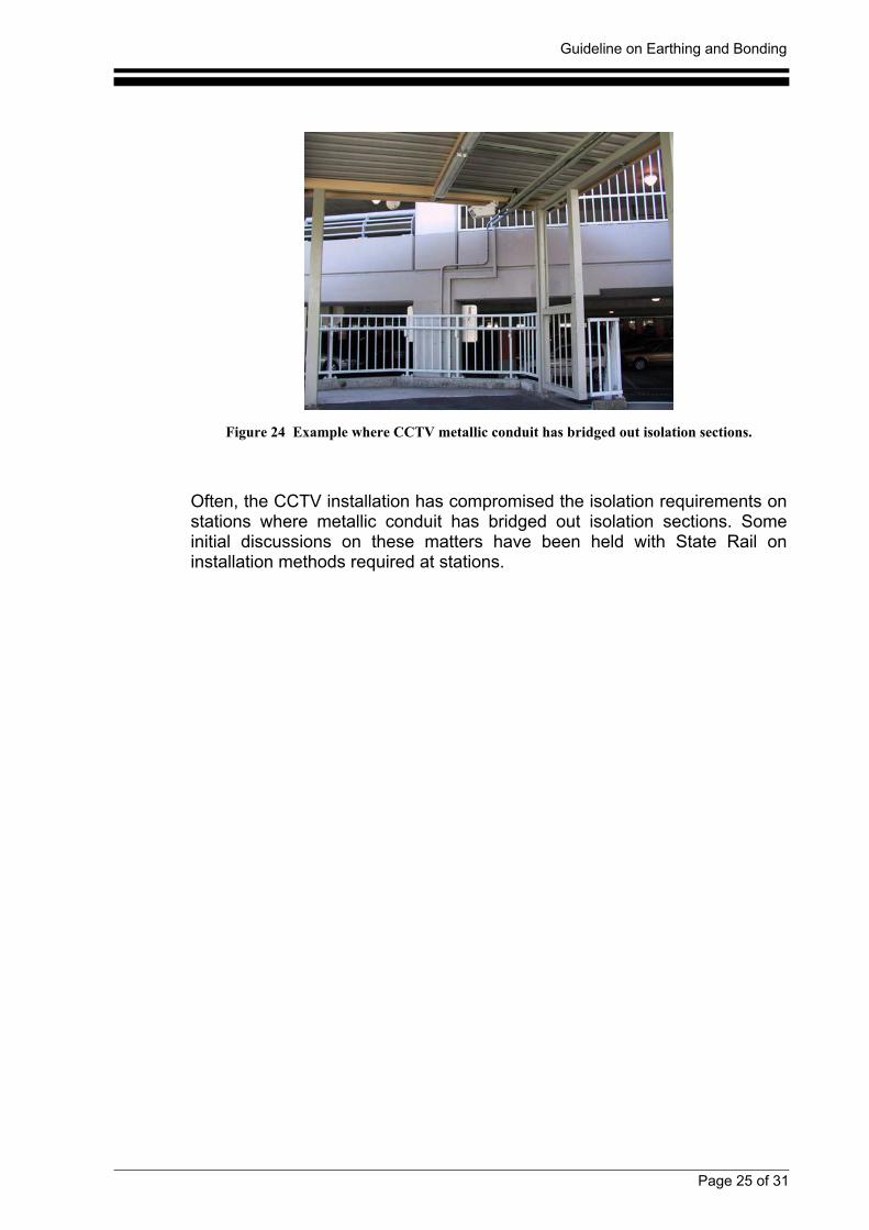
Figure 24 Example where CCTV metallic conduit has bridged out isolation sections.
Often, the CCTV installation has compromised the isolation requirements onstations where metallic conduit has bridged out isolation sections. Someinitial discussions on these matters have been held with State Rail oninstallation methods required at stations.
Guideline on Earthing and Bonding
Page 26 of 31
6. Conclusion
Earthing and bonding issues at railway stations are predominantly attributedto the interface issues between overhead wiring structures, awnings orcanopies and services entering the rail corridor.
The most common problems are related to the bonding arrangementsassociated with overhead wiring structures in close proximity to:
• metallic awning supports,
• metal fencing,
• earthed metallic objects such as lighting standards, vendingmachines, water pipes, telephone booths, fire hydrant apparatusand CCTV's.
Generally, most stations in the electrified system are appropriately bonded atoverhead wiring structures, foot bridges and traffic bridges. Spark gaps arean essential safety device and are critical to the 1500V traction systemprotection and bonding scheme. As such, any maintenance or constructionwork involving these items should be carried out in accordance to RailCorp’spolicy requirements.
Another common problem effecting stations is the interface of the railwayboundary fence to station fencing. This situation can contribute to theeffects of electrolysis. Some of these defects are attributable to additionalmetallic fencing panels and fencing wire installed to prohibit illegal access atthe ends of platforms and the lack of an isolating panel or isolation sectionsof fencing.
Many stations have situations where interface issues between RailCorp’ssupply earth and another Network Operator supply earth apply. At theselocations, any maintenance work or upgrading work must be monitored toensure the interface conditions are not compromised. It is recommendedthat appropriate signage would be beneficial to alert contractors and otherpersonnel to this issue. Additionallly, installation of radiating services suchas CCTV must be carefully designed and controlled to ensure isolationsections are not bridged.
Issues such as high voltage transmission lines sited above sections ofstation canopies or roof areas must also be monitored when planning anyupgrading work.
Another safety issue concerning the proper installation and bonding ofstructures is the risk of causing a signalling failure due to incorrectconfiguration of spark gap bonds. This safety issue highlights the need for aproper detailed design approach, especially for larger complex stations.
Guideline on Earthing and Bonding
Page 27 of 31
The siting of services on stations such as vending machines, ticketingmachines, telephone booths, water taps, etc must be considered in relationto earthing and bonding principles.
With the further roll out of station upgrading projects, the issues associatedwith railway station interfaces with other buildings, structures, bus-railinterchanges etc will become more prevalent. Greater control over this workis crucial to ensure RailCorp’s standards are met in future.
Past deficiencies in relation to earthing and bonding are due to thepiecemeal approach often adopted by the station upgrading work. Projectsmust not limit their scope to their own upgrading work without addressing theglobal implications of earthing and bonding.
At more complex stations, some configurations pose a difficult situation tosegregate the 1500V circuits from other parts of the station. Often the bestcompromise option at these stations is to treat all metallic structures as onebody. This alternative, while not necessarily the optimal option, is consideredthe most pragmatic option for some situations due to the numerousplatforms, stanchions, service lines, stairs, handrails, canopy supports andlighting columns involved. However, there are negative trade-offs with thisoption where the sphere of influence is greatly increased under faultconditions. Further, this option requires engineering analysis and bondingdesign to ensure the appropriate safety criteria is maintained.
It is emphasised that appropriate configuration documentation for earthing,bonding and electrolysis mitigation equipment is essential to minimise therisks associated with these issues. This configuration documentation mustbe incorporated into any new project involving upgrading work to ensureintegrity of the assets and allow for maintainability.
It is evident that there is no simple formula for solving existing problems,especially at more complex stations. In these situations, each station mustbe assessed on its own merit, taking into consideration the existingconfiguration and the proposed work to determine the best optimal solution,culminating in the production of an earthing and bonding design.
The principle of separation is the best option that overcomes the majority ofearthing and bonding issues, especially for limited new work. Obviously, inexisting installations where this separation is already compromised, it can bean expensive exercise to either relocate all offending metallic supports orrevert to other alternatives.
From a risk management perspective, the process of “designing out”earthing and bonding issues must be the first choice in the hierarchy ofmanaging these risks. This is especially so in relation to proposed newupgrading work.
It is stressed that the most cost effective and safest configuration for anynew canopy or building work is to incorporate the principle of separation, iffeasible, into the design stage. If earthing and bonding issues are integratedinto the design stage, substantial cost savings can be achieved as well asdrastically reducing the risk exposure to persons, property and RailCorp.
Guideline on Earthing and Bonding
Page 28 of 31
APPENDIX 1
The following are selected extracts from relevant RIC (RailCorp) documents dealingwith railway station earthing and bonding requirements. The extracts are not acomprehensive set of documentation but have been compiled to concisely highlightthe major issues associated with earthing and bonding.
EP 12 10 00 21 SPLow Voltage Installations Earthing
1.1. Clearances from 1500 V Structures and Other Earthed MetalworkA 2 m distance shall be maintained between the earthing system of the low voltageinstallation, including earthed metalwork for example fences, vending machines andtelephone cabinets, and any overhead wiring structures which are not bonded to thesame earthing system or metalwork connected to a separate earthing system.
1.6. Lineside Metal Fencing or Signal TroughingA 2 m clearance must be maintained between any metal connected to the railwaystations low voltage earth and any continuous metal structure, such as a fence orsignal troughing, that is not intentionally connected to the earthing system. Where the2 m clearance cannot be obtained, a suitable approved method such as installing twoisolating breaks 2 m apart in the continuous metal structure shall be used.Alternatively the situation can be proved safe by calculation and testing for dangeroustouch voltages in accordance with the ESAA Substation Earthing Guide.
1.7. Metallic ConduitsIn general metallic conduits are not permitted to be installed underground or inconcrete within the electrified area due to the presence of stray 1500 V dc leakagecurrents. However, in practice short lengths should not present a problem, therefore, ifa situation arises where a short length of buried metallic conduit is the preferredmethod then the definition of appreciable dc leakage current from SpecificationEP12000002SP - "Low Voltage Distribution and Installations Earthing References andDefinitions" can be applied
2. Overbridge having 1500 V Overhead Wiring and Low Voltage WiringAttached2.1. Connection to ElectrodeAn overbridge at any railway station in the electrified area having low voltage cables incontact with the bridge will require the bridge to be connected to a 6 m electrode usinga 70 mm² copper conductor, refer to section 2.1.1. The electrode is to be located asclose as possible to the bridge and installed as detailed in sections 2.1.2 and 2.1.3.The 70 mm² conductor shall be protected against mechanical damage as detailed in
Guideline on Earthing and Bonding
Page 29 of 31
section 1.5 and be secured to the over bridge by no lesser security than a crimpedclosed lug, lock-nutted onto a stud of minimum size 12 mm.
3. Railway Station InterfacesWhere a railway station adjoins with another building or structure, such as a bus railinterchange or a footbridge that connects a railway station with a shopping centre, thedesign shall not allow the extension of the RIC low voltage earthing system beyondthe railway corridor. This includes all metallic structures and services, such asawnings, fences, pipes and electrical wiring and conduits. The interface should be welldefined and easily observable and where any doubt exists the situation shall beproved safe by calculation and testing for dangerous touch voltages in accordancewith the ESAA Substation Earthing Guide.The metalwork of the structure that has been isolated from the station may beconnected to an MEN earthing system.
C 4501Metallic Lineside Fencing in Electrified Areas When constructing metallic fencing along the 1500V DC electrified rail corridor, thefollowing key electrical aspects must be considered:
• The transfer of touch and step potentials along the metallic fencing, and • The mitigation of electrolysis.
EP 12 30 00 01 SPElectrolysis From Stray DC Current
1 Introduction….Ideally, all current should return through the rails, but since they are in closecontact with the ground through the sleepers and ballast, some current will 'leak' fromthe rails and return to the substation through the ground. This is called 'stray current'or 'leakage current'…..
…..The problem of minimising electrolysis is closely related to the problem of earthingand/or bonding of metallic structures to prevent electric shock to people. The solutionsto both problems have to be a compromise since the 'best' solution for one situationresults in major problems for the other situation.
5 Minimisation TechniquesThe following minimisation techniques are recommended for any person engaging inwork within the `railway corridor' and near `1500 V track'. All mandatory requirementsare covered in relevant documents.• Overhead wiring structures which are bonded to rail via a spark gap do not contact
earthed services such as station awnings, fences, water pipes etc.
Guideline on Earthing and Bonding
Page 30 of 31
• In tunnels, on bridges and under air-space developments, there is no contactbetween rails and reinforcing or other steelwork.
• Keep metallic services 'away' from the track so there is less chance of 'picking up'appreciable dc leakage current.
• All low voltage supplies use Isolating transformers. Local Electricity Distributorneutral and earthing systems should not enter Railway Corridor.
• Water and Gas pipes servicing buildings on the Railway Corridor and near 1500 Vtrack to have an isolating joint installed at the boundary.
• Fencing at stations and electrical substations is not to be connected to the linesidefencing.
• Ensure all metallic structures such as footbridges, bus shelters etc. are isolated atboundary of Railway Corridor. This is usually achieved by installing two 'gaps' inthe steelwork, about 2m apart. Special care is needed if there is lighting installed,to ensure the local Electricity Distributor's earth is not connected to the steelworkwhich forms part of any overhead wiring structure, station or bridge.
EP 12 10 00 22 SP Buildings and Structures Under Overhead Lines
1. High Voltage Transmission LinesWhere a building or structure is located such that possible risks could arise due toinduction, touch or step voltages, infringement of safety clearances to conductors, orthe failure of line materials or structures, the earthing system of the building orstructure shall meet the requirements of the Electricity Council of NSW document EC20 - "Guidelines for the Management of Electricity Easements".
EP 12 00 00 02 SP Low Voltage Distribution and Installations EarthingReferences and Definitions This document lists the publications and drawings that are referenced in associateddocuments and can provide extra background information.
EP 12 10 00 20 SP Low Voltage Distribution Earthing
2. Supply from Local Electricity Distributor's Network2.1. General
Guideline on Earthing and Bonding
Page 31 of 31
The MEN system of a local Electricity Distributor must not be allowed to pick upappreciable dc leakage current. The recognised method of achieving this is to ensurethe earth and neutral of the MEN supply is physically isolated from any part of thesupplied installation, including earthed metalwork (such as pipes, fences, overheadearth wires or troughing).This document is based on the use of an isolating transformer to separate the localElectricity Distributor's MEN earth and neutral from the RIC distribution systems directearthing system……..
2.3. Isolating TransformerAn isolating transformer shall be connected between the local Electricity Distributor'sservice equipment and the supply main switchboard to physically isolate the earth andneutral of the MEN supply from any part of the RIC distribution system, includingearthed metalwork (such as pipes, fences, overhead earth wires or troughing).The isolating transformer shall comply with SRA Specification A-844 (now RICspecification EP 17 00 00 11 SP). The transformer shall be installed with a signprominently displayed on its case stating that it is double insulated and conforms toAS 3108……….