earthing for lighting protection - indian...
TRANSCRIPT

Page 35
Earthing for Lighting Protection
Shri P.Venkata Ramana, Senior Professor Signal/IRISET
The Perimeter RingEarth (PRE) or Ring Earthare required for safetycritical installations such asElectronic InterlockingSystems for providingprotection from lightning.RDSO typical bonding &earthing arrangement isavailable for provision ofPerimeter Ring Earth for
Electronic Interlocking installations. But it neitherprovides guidelines for its design nor provides methodto check its effectiveness. More ever, the arrangementis typical but not specific. Specific designs will varyfor different installations especially where buildingsare different in shapes and sizes, varying soilresistivities from place to place and varying flashdensity of lightning from region to region.
The Perimeter Ring Earth is the earth-terminationsystem. Earth- termination system is the continuationof the air-termination system and down conductors. Itdischarges the lightning current to the earth,establishes equipotential bonding between the downconductors and controls the potential in the vicinityof the building walls.
The Perimeter Ring Earth is essentially a type BEarth as per IEC / EN 62305 standards. Earthingsystem based on Perimeter Ring Earth requires designfor a specific installation and requires properinstallation practices. This article provides an insightinto design and installation of Perimeter Ring Earthand its effectiveness as per IEC/EN 62305 standards.
The topic is dealt in four sections.(i) Calculation for requirement of number of
Earth Electrodes in a Perimeter Ring Earth -illustrates the criteria for sufficiency of earth electrodesprovided in a Ring Earth for the measured soilresistivity, level of class of lightning protection andarea of the building.
(ii) Selection of Earth Electrodes - lists variousmaterials available for earth electrodes and theminimum dimensions required for the earth electrodes.
(iii) Soil Resistivity - discusses various parametersof soil resistivity and measurement of soil resistivity
by Wenner method.
(iv) Norms and Precautions - discusses the normsand precautions to be followed in installation ofPerimeter Ring Earth.
The definitions of technical terms are given at theend.
I. CALCULATION FOR REQUIREMENT OFNUMBER OF EARTH ELECTRODES IN APERIMETER EARTH
Type B Earth electrodes are ring earth electrodesencircling the object to be protected.
The total length of Earth electrodes provided inPerimeter Ring Earth depends upon 3 parameters (i)total area of building to be protected from lightning(ii) class of lightning protection being provided ClassI or II or III or IV (iii) Mean Soil Resistivity in thevicinity of the building.
Criteria for effective lightning protection is thatthe mean radius, r of the area encircled by a perimeter
ring earth must be not less than the specified minimumlength, l1.
To determine the mean radius r, the area underconsideration is transferred into an equivalent circulararea and the radius is determined as shown in abovefigures.
Where r = Mean radius, A = Area of the buildingbeing protected
r =

Gyandeep
Page 36
The specified minimum length, l1 can be obtained from the following graph.
A minimum earth electrode length of 5 m is required for class of LPS III and IV. For class of LPS I and II the length of the earth electrode is defined as a function of the soil resistivity. The minimum length of each earth electrode is (i) l1 x 0.5 for vertical or inclined earth electrodes (ii) l1 for radial earth electrodes As vertical earth electrodes are preferred to radial earth electrodes in our Perimeter Ring Earth installations, the minimum specified total earth electrode length shall be half of the value, l1 obtained from the graph for a given soil Resistivity and class of lightning protection. If the required value of l1 is greater than the value of r corresponding to the structure, further radial or vertical earth electrodes must be added whose relevant lengths lr (radial/horizontal) and lv (vertical) result from the following equations: lr = l1 r lv = ( l1 r ) / 2 For example: Let us consider the following example.
Panel with Panel Processor are having overall dimensions 16m x 9m. The IPS is fed from unprotected power source (normally from a CLS Panel). It requires, therefore, Class I Protection.
The Earth Resistivity is measured around the building at 14 places, 1m away from periphery of the building and whose average value is
The Earth Resistivity can be measured using an Earth Meter by Wenner method. Wenner method is explained in the Soil Resistivity section. The building is to be provided with the Perimeter Ring Earth for lightning protection. Now the question is that how many earth electrodes are to be provisioned for Perimeter Ring Earth for protecting the building housing safety critical equipment from lightning effectively?
A = Area of the building being protected = 16 x 9 m2 = 144 m2 r = Mean radius = = 6.77 m From the graph, the minimum length of the earth electrand for Class I Lightning protection, the value, l1 is 20m. For vertical earth electrodes, the minimum length of the earth electrode has to be I1 x 0.5. Therefore, the minimum length of the earth electrode, is 20 x 0.5 m = 10m. When compared r with l1, r is less than l1, which is not met the criteria as specified. In which case, the additional earth electrodes are required to be provided and whose length shall be lv = ( l1 r ) / 2

Gyandeep
Page 37
lv = ( 20 - 6.77 ) /2 = 6.62 m Therefore, the total length of earth electrodes required for the Perimeter Ring Earth will be Lv = 10m + 6.62m = 16.62m If earth electrode lengths of 2.0m are being used for Perimeter Earth, the number of earth electrodes require are = 16.62 / 2.0 II. SELECTION OF EARTH ELECTRODES Commonly used earth electrode materials and their minimum dimensions are listed in table below.
Material
Configuration
Minimum Dimensions
Earth Rod, Ø
Earth Conductor (mm2
)
Earth Plate (mm)
Hot-dip Galvani
sed Steel
Solid round
14 78
Pipe 25
Solid Tape
90
Solid Plate
500x500
Lattice Plate
600x600
Copper, Tin-
plated copper
Stranded 50
Solid Round
15 50
Solid tape 50
Pipe 20
Bare Steel
Stranded 70
Solid Round
78
Solid tape 75
Copper- coated steel
Solid Round
14 50
Solid tape 90
Stainless steel
Solid Round
15 78
Solid tape 100
Mechanical and electrical characteristics
as well as corrosion resistance properties must meet the requirements of the IEC 62561 series
Must be embedded in concrete for a minimum depth of 50 mm
Lattice plates should be constructed with a minimum total conductor length of 4.8 m
Different profiles are permitted with a cross-section of 290 mn2 and a minimum thickness of 3 mm
In case of a type B foundation earth electrode, the earth electrode shall be correctly connected at least every 5 m with the reinforcing steel
Hot-dip galvanised steel Hot-dip galvanised steel can also be embedded in concrete. Foundation earth electrodes, earthing and equipotential bonding conductors made of galvanised steel in concrete may be connected with reinforcing bars. Steel with copper sheath In case of copper-sheathed steel, the comments for bare copper apply to the sheath material. Damage to the copper sheath, however, presents a high risk of corrosion for the steel core. Therefore, a completely closed copper layer must always be applied.
Bare copper Bare copper is very resistant due to its position in the electrochemical series. Moreover, when
Gyandeep
Page 38
connected to earth electrodes or other -
additionally provides cathodic protection, -
Stainless steel Certain high-alloy stainless steels according to EN 10088-1 are inert and corrosion-resistant in the ground. The free corrosion potential of high-alloy stainless steels in normally aerated soils is mostly close to the value of copper. Since the surface of stainless steel earth electrode materials passivate within a few weeks, they are neutral to other (more precious and non-precious) materials. Stainless steels should consist of at least 16% chromium, 5% nickel and 2% molybdenum. Stainless steels without molybdenum are not suited for use as earth electrode material and are not permitted by the standard.
Other materials Other materials can be used if they are particularly corrosion-resistant in certain environments or are at least equivalent to the materials listed in table. III. Earth Resistivity Earth resistance, RA The magnitude of the earth resistance, RA plays only a minor role for protecting a building or installation against lightning. More important is that the equipotential bonding is established consistently at ground level and the lightning current is safely distributed in the ground. Nevertheless, the Earth Termination system constitute the important ingredient of Lightning Protection System.
E
E , which is decisive for the magnitude of the earth resistance RA of an earth electrode, depends on the soil composition, moisture in the soil and the temperature. It can fluctuate within wide limits. Seasonal fluctuations Extensive measurements have shown that the earth resistivity varies greatly depending on the burial depth of the earth electrode. Owing to the negative temperature coefficient of the
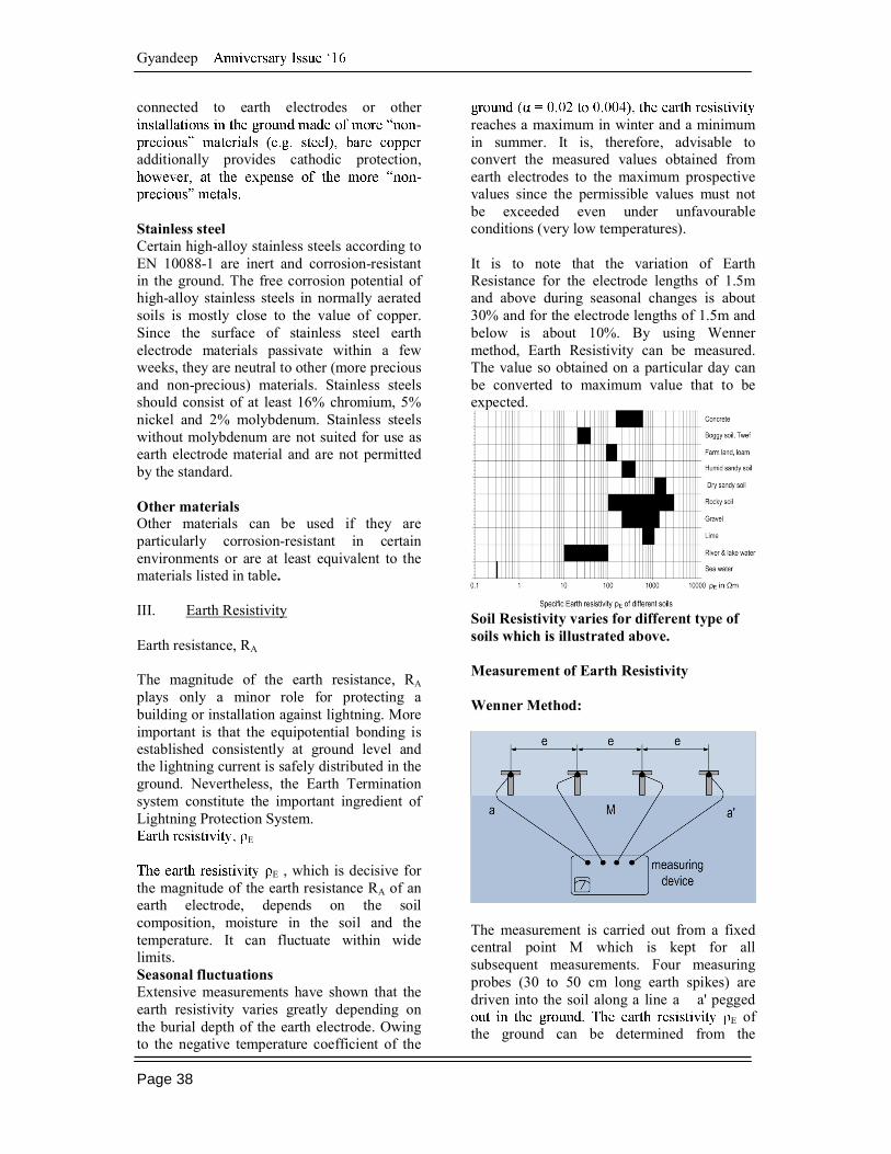
reaches a maximum in winter and a minimum in summer. It is, therefore, advisable to convert the measured values obtained from earth electrodes to the maximum prospective values since the permissible values must not be exceeded even under unfavourable conditions (very low temperatures). It is to note that the variation of Earth Resistance for the electrode lengths of 1.5m and above during seasonal changes is about 30% and for the electrode lengths of 1.5m and below is about 10%. By using Wenner method, Earth Resistivity can be measured. The value so obtained on a particular day can be converted to maximum value that to be expected.
Soil Resistivity varies for different type of soils which is illustrated above. Measurement of Earth Resistivity Wenner Method:
The measurement is carried out from a fixed central point M which is kept for all subsequent measurements. Four measuring probes (30 to 50 cm long earth spikes) are driven into the soil along a line a a' pegged
E of the ground can be determined from the

Gyandeep
Page 39
measured resistance R: E = Where e = robe spacing in meters
(measured Voltage, V / measured current, I )
E depth according to the probe spacing, e Earth rod The earth resistance RA of an earth rod is calculated as follows: RA E e ( 2 l / r ) Where RA =
E = l = Length of the earth rod in m r = Radius of the earth rod in m However, when earth electrodes are interconnected in Ring formation for Perimeter Ring Earth and in such cases, the earth resistance RA of an earth rod is RA= E
2 d ) loge E / 3 d ) d = Where RA =
E = d = Diameter of a ring earth electrode, the area of the equivalent circuit or a hemispherical earth electrode A = Area (m2) of the enclosed area of a ring earth electrode R = Quarter width of the strip earth electrode The lightning current i raises the object to be protected to the earth potential UE with respect to reference earth.
UE = i RA + ½ L di/dt
as the distance from the earth electrode increases. The magnitude of the earth resistance must be limited to minimise touch and step voltages. The conventional earthing impedance of earth electrodes depends on the
maximum value of the lightning current and of the earth resistivity. As an approximation, the effective length of the earth electrode in case of lightning currents is calculated as follows: leff = 0.2 E ) Where leff = Effective length of the earth electrode in m î = Peak value of the lightning current in kA
Earth rods are easy to assemble and achieve excellent constant earth resistances without requiring excavation work and damaging the ground, these earth electrodes are also suitable for improving existing earth-termination systems.
Earth Resistance for a given electrode length and soil resistivity is given as above. IV. NORMS & RECAUTIONS 1. A common earth-termination system is to be preferred for the different electrical systems (lightning protection systems, low-voltage systems and telecommunications systems). 2. This earth-termination system must be connected to the equipotential bonding system via the main earthing busbar (MEB). 3. The The earth electrode must be spaced at equal interval.

Gyandeep
Page 40
4. The spacing between 2 earth electrodes shall be minimum 2 times the length of the electrode. 5. The earth electrodes are preferably to be placed at building corners, as down rods of air-termination system normally be run thru the corners of the building. 6. The earth electrode must be in contact with the soil for at least 80 % of its total length to ensure that a type B earth electrode can be used as a base for calculating the separation distance. 7. The minimum lengths of type B earth electrodes depend on the class of LPS. In case of classes of LPS I and II, the minimum earth electrode length also depends on the soil resistivity. 8. The number of additional earth electrodes must not be less than the number of down conductors, but at least two. These additional earth electrodes should be connected to the ring earth electrode so as to be spaced equally around the perimeter. 9. The lightning current is not conducted to earth at one point via the earth electrode, but rather energises a certain area around the earth electrode. 8. Since the IEC 62305-3 (EN 62305-3) standard requires consistent lightning equipotential bonding, no particular value is specified for the earth resistance. In general, a
low frequency) is recommended. 9. The requirements on the minimum earth electrode length must be taken into account depending on the class of LPS. 10. When installing the ring earth electrode, it must be also observed that it is buried at a depth > 0.5 m and 1 m away from the building. 11. If the earth electrode is driven vertically into the soil, it reduces the step voltage and thus controls the potential around the building. 12. This ring earth electrode should be installed in natural soil. If it is installed in back
filled or soil filled with construction waste, the earth resistance is reduced. 13. When choosing the earth electrode material with regard to corrosion, local conditions must be taken into consideration. It is advisable to use stainless steel. This earth electrode material does neither corrode nor subsequently require time consuming and expensive reconstruction measures for the earth-termination system such as removal of paving stones, tar surfaces or even steps for installing a new earthing material. 14. In addition, the terminal lugs must be particularly protected against corrosion.
15. In rocky or stony ground, surface earth electrodes such as ring or radial earth electrodes are often the only way to create an earth-termination system. 16. Earth entries made of galvanised steel must be protected against corrosion over a distance of at least 0.3 m above and below the surface of the earth. Generally, bituminous coatings are not sufficient. A moisture-proof sheath, e.g. butyl rubber strips, heat-shrinkable sleeves or preferably stainless steel, provides protection.
17. Buried connection points: Cut surfaces and connection points in the ground must be designed so as to ensure that they have an equivalent corrosion resistance as the corrosion protection layer of the earth electrode material. Connection points in the ground must therefore be equipped with a suitable coating, e.g. wrapped with an anticorrosive tape. 18. When filling ditches and pits where earth electrodes are installed, pieces of slag and coal must not directly contact the earth electrode material. The same applies to construction waste. 19. If it is not possible to encircle the structure by means of a closed ring, the ring must be complemented by means of conductors inside the structure. Pipework or other permanently conductive metal components can also be used for this purpose.
20. Connecting cables / terminal lugs

Gyandeep
Page 41
between earth electrodes and down conductors should be laid in concrete or masonry until they are above the surface of the earth. 21. If the connecting cables are led through the ground, terminal lugs with e.g. 1 x 16 mm2 Cu, stainless steel (V4A), or fixed earthing terminals must be used. 22. Earthing conductors installed in the masonry can also be led upwards without corrosion protection. TERMINOLOGY Earth is the conductive ground and the part of the earth in electrical contact with an earth electrode whose electric potential is not
describes both a place and a material, e.g. humus, loam, sand, gravel and rock. Reference earth (neutral earth) is the part of the earth, especially the surface of the earth outside the area influenced by an earth electrode or an earth-termination system, in which no perceptible voltages arising from the earthing current occur between two arbitrary points Earth electrode is a conductive part or several conductive parts in electrical contact with earth which provide(s) an electrical connection with the earth (also foundation earth electrodes). Earth-termination system all conductively interconnected earth electrodes which are physically separated or metal components acting as such (e.g. reinforcements of concrete foundations, metal cable sheaths in direct contact with earth). Earthing conductor is a conductor which connects a system part to be earthed to an earth electrode and which is installed above the ground or insulated in the ground. Foundation Earth Electrodes consists of one or several conductors embedded in concrete which are in contact with earth over a large area.
Ring earth electrode earth electrode that forms a closed ring around the structure underneath or on the surface of the earth. Earth resistivity E is the electric resistivity of the earth. It is
and represents the resistance of an earth cube with 1 m long edges between two opposite sides of the cube. Earth resistance RA of an earth electrode is the resistance of the earth between the earth electrode and reference earth. RA is practically an effective resistance. Earth surface potential is the voltage between one point of the surface of the earth and reference earth Touch voltage is the part of the earth surface potential which can be bridged by persons, the current path via the human body running from hand to foot (horizontal distance from the touchable part of about 1 m) or from one hand to the other. Step voltage is the part of the earth surface potential which can be bridged by persons taking one step of 1 m, the current path via the human body running from one foot to the other. REFERENCES 1. IEC/ EN 62305 - 3 & 4 Lightning Protection Standards 2. Lightning Protection Guide, 3rd updated edition as of December 2014 ISBN 978-3-9813770-1-9 3. RDSO typical drawing for earthing and connections for EI systems