addendum - tarm biomass wood boilers , pellet … before starting your boiler installation, we urge...
TRANSCRIPT


NOTE: Installation must be done in accordance with all State (Provincial) and Local Ordinances, which may differ from and take precedence over this Owners Manual, and in accordance with the following codes:
ANSI/NFPA No. 31 - Installation of Oil Burning Equipment; ANSI/NFPA No. 70 - National Electric Code; ANSI/NFPA No. 211 - Chimneys, Fireplaces, Vents, Solid Fuel-Burning Appliances; and ANSI/NFPA No. 54 - The National Fuel Gas Code
These documents are available from the: National Fire Protection Association
1 Batterymarch Park Quincy, MA 02269
Tel: 1-800-593-6372
Re-Printed October 2011

ADDENDUM
Before starting your boiler installation, we urge you to read and consider this addendum. Tarm Biomass strongly recommends the installation of a Termovar automatic, thermally operated, 3-way mixing valve or loading unit with all wood or multi-fuel boilers. When cold water returns to the boiler it causes sweating and a cold environment for the fire which causes creosote and poor combustion. The Termovar insures a minimum return water temperature of 160° F in the boiler. This increases efficiency, helps prevent creosote, and considerably extends the life of the boiler. The Termovar helps create more efficient burning and is a recommended part of any boiler installation. Please call Tarm Biomass with any questions.
1-800-782-9927
IMPORTANT NOTICE:
Any tubing used for Radiant Floor Heating with a Tarm Biomass boiler MUST have an oxygen barrier.


INTRODUCTION AND IMPORTANT INFORMATION PAGE 1 ______________________________________________________________________________________________________________________________________________________________________________________
INTRODUCTION Thank you for purchasing an HS-Tarm EXCEL boiler. Your boiler was manufactured by BAXI/HS-Tarm, a world leader in hot water (hydronic) heating for over 70 years. The HS-Tarm EXCEL conforms to traditional high standards for quality and reliability. It is truly state-of-the-art in high efficiency, clean-burning multi-fuel heating. When installed and operated properly, your boiler will operate at over 80% efficiency on wood fuel and 83% to 87% on oil or gas. If treated properly and operated according to the guidelines in this manual it will provide years of safe, dependable and economical heating. The Tarm EXCEL boilers have been tested and listed by the Omni Test Laboratories Inc. The test standards used are UL 391-1995, CAN/CSA B366.1-M91, UL726, ANSI Z 21.13-2000, and CSA4.9-M2000 to satisfy code requirements in the United States and Canada. This manual contains installation, operation, and maintenance guidelines for all models in the HS-Tarm EXCEL series of boilers. Your heating system design and installation should be done by a competent professional contractor. NOTE: Installation must be done in accordance with local ordinances, which may differ in some ways from this owners manual.
Please note that the installation instructions refer to specific makes of controls and accessories. Equivalent makes and models of these devices may be used successfully. The installing contractor is the best judge of a system's specific requirements, as well as of local availability of different devices. However, be certain that no substitutions are made for the standard safety equipment, control panel and relief valves that we have supplied with the boiler. The installation of these devices is absolutely necessary for safe operation of the boiler and protection of the heating system. Every effort was made during the writing of this manual to produce a guide which would be easy to understand and contain all pertinent information.
NOTE: 1. We urge you to thoroughly familiarize yourself with this manual before installing and operating the boiler.
2. Please keep this manual handy for future reference. Included is information which will make operation of your new boiler an easier and more enjoyable experience. If questions arise during installation, operation, or maintenance, or if you are in doubt about any aspect of your boiler, please contact your installer, your dealer or TARM USA, Inc.
1

INTRODUCTION AND IMPORTANT INFORMATION (continued) PAGE 2 _____________________________________________________________________________________________________________________________________________________________________________________________________
What is the HS-Tarm EXCEL boiler? The EXCEL is a multi-fuel boiler designed and constructed for the highly efficient combustion of firewood, oil, propane or natural gas. Do not burn other fuels in the EXCEL. WOOD COMBUSTION Very important to the function and design detail is the wood fire combustion draft fan. The primary and secondary air are both fed through air ducts into the firebox with the precise velocity necessary for proper combustion. The primary air is introduced into the top of the firebox. The secondary air is forced through the refractory, where it is heated and distributed through two channels and many air nozzles on each side of the center slot in the refractory. The secondary air is injected with high velocity directly into the hot gases and flame to complete the wood combustion. A very important design detail of the EXCEL is the refractory and combustion tunnel in the heart of the boiler. These refractory blocks ensure that the wood combustion temperatures exceed 1800° F, several hundred degrees more than is needed to burn wood smoke and gas. This combustion is extremely efficient and virtually smoke and creosote free. The optimal and environmentally desirable combustion of wood with the highest efficiency demands the correct proportional mixture of gas from the wood and combustion air from the fan. The heat is transferred to the boiler water by means of heat exchange tubes located behind the firebox and refractory combustion tunnel. OIL OR GAS COMBUSTION The oil or gas burner supplied with your EXCEL boiler has completely separate combustion and heat exchange chambers from those for the wood. Turbulators in the heat exchange tubes, and the use of high efficiency burners, results in fossil fuel utilization as good as or better than most high efficiency boilers available in our North American market. RESPONSIBILITY The user is responsible for the operation of the boiler and that the guidelines in this manual for firing are observed and followed. Not following the instructions can result in lower efficiency and environmental pollution because the desired clean flue gas is not obtained. Furthermore, misapplication may reduce the boiler’s life. The correct operation and installation is the best guarantee of a properly operating boiler with a long lifetime and less pollution. It is a prerequisite that the user has the will and the right attitude towards firing with wood. In spite of everything, some work must be done to benefit from this environmentally desirable and economically profitable method of heating your home.
2
INTRODUCTION AND IMPORTANT INFORMATION (continued) PAGE 3 ______________________________________________________________________________________________________________________________________________________________________________________
MAINTENANCE It is also the responsibility of the user that the boiler be cleaned and maintained according to:
• normal practice, • the instructions of this manual, • instructions for the controls or equipment, and • other circumstances described in the written warranty.
SAFETY If an unsafe condition occurs it is to be repaired as soon as possible by a qualified service person. Outlets, ventilating ducts, fresh air conduits, and others must not be closed or clogged up.
3

(Intentionally left blank) PAGE 4
4
INTRODUCTION AND IMPORTANT INFORMATION (continued) PAGE 5 ______________________________________________________________________________________________________________________________________________________________________________________ PLEASE READ THIS PAGE CAREFULLY!
This boiler has a limited warranty which is included with your boiler as a separate enclosure. To validate your warranty, detach the postcard, fill in all information requested, and return the card to TARM USA, INC. Please always raise questions or warranty claims with your installer/dealer who delivered the boiler to you. The installer/dealer then passes the claim on to TARM USA, INC., IF NEED BE. However, claims may also be raised directly with TARM USA, INC. General Information Please read the literature enclosed by the manufacturers regarding the various accessory devices. These devices are warranted by the manufacturer, NOT by TARM USA, INC. These accessory devices must be installed and used according to the recommendations of the manufacturer unless instructed otherwise in this manual. NOTE: All boilers must be installed in accordance with national, state and local plumbing, heating and electrical codes, and the regulations of the serving electric, water and gas utilities. Plumbing diagrams in this manual are for basic information only and may not show all valves, vents, fittings, etc that are normally included in finished boiler installations. All systems should be designed by competent contractors, and only persons knowledgeable in the layout and installation of heating systems should attempt the installation of any boiler. It is the responsibility of the installing contractor to see that all controls are installed correctly and that they are operating properly when the installation is complete. If any fans are used in the fuel storage area, they should be installed so as not to create negative pressure in the room where the solid-fueled burning appliance is located. Please read carefully the section “OPERATION DURING SUMMER”. Failure to protect your boiler from condensation during the warmer months MAY VOID YOUR WARRANTY! SEE PAGE 48. Do not use this boiler if any part has been under water. Immediately call a qualified service technician to inspect the boiler and to replace any part of the control system and any gas control which has been under water. Homeowners should read and familiarize themselves with “BOILER OVERHEATING” and “OPERATING IN THE EVENT OF POWER FAILURE”. SEE PAGES 53 TO 55.
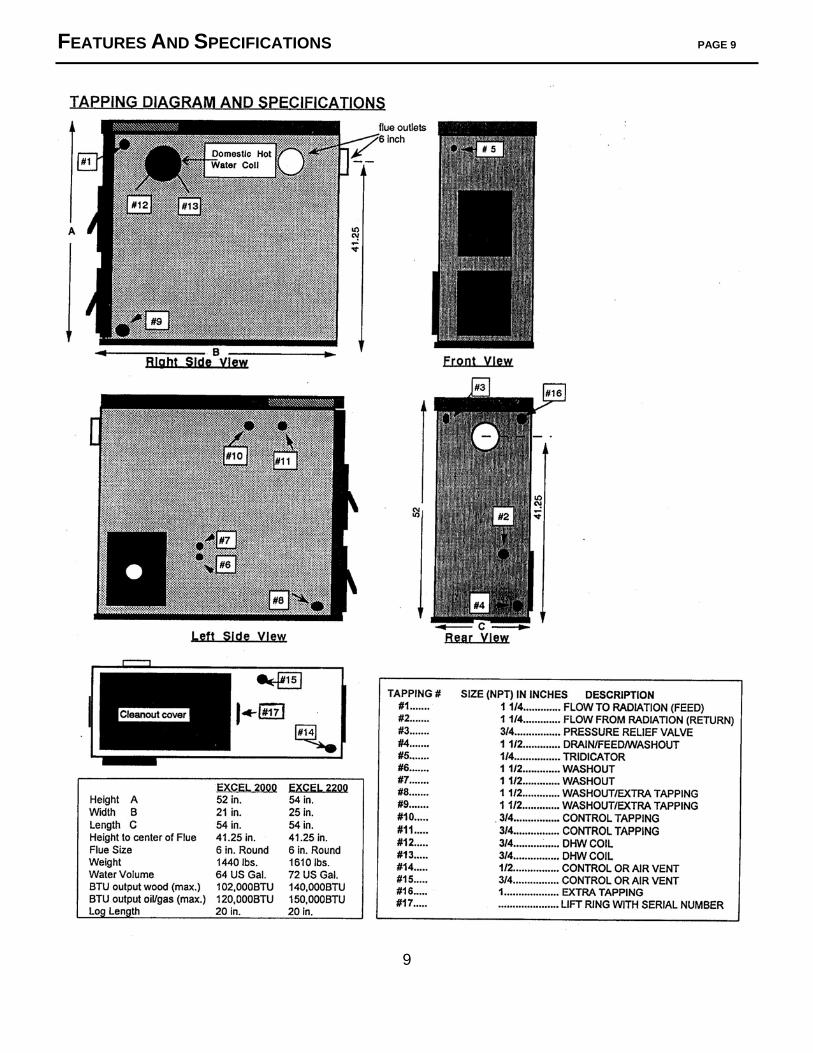
WARNING: Do not use gasoline, kerosene or other flammable liquids to start or maintain solid-fuel fires in your boiler. Serious burns and property damage may result. WARNING: Do not store any combustibles, including fuel for the boiler, within the fire clearances specified below in “Installation Information”. Keep fuel clear of the fuel-loading and ash-removal access areas. WARNING: This boiler is designed to burn wood. Both hard and soft woods may be used, but under no circumstances should you burn coal or small pieces of wood or wood waste that can fall through the center slot in the refractory causing a blockage. Installation Information The boiler must be connected to a tile-lined masonry flue or other Type HT approved chimney. No other appliance should be connected to this flue. Consult your local building inspector for chimney requirements, and install the boiler in accordance with all applicable codes. The boiler requires adequate fresh air supply for efficient and safe operation. For more information refer to NFPA Standard #31 and page 6. The boiler must be positioned to provide minimum clearances from combustibles or combustible surfaces as follows: LEFT SIDE=24”; RIGHT SIDE=12”; TOP AND REAR=18”; FRONT=36”. There must be a minimum clearance of 18” between smoke pipe and all combustible surfaces. Use the wicking and pipe dope supplied with the boiler to seal all threaded connections to the boiler and Termovar. When references are made to tapping numbers, please refer to Page 9. Do not use self-contained, non-electric zone valves on the main heating zone as it is to be used as the overheat/dump zone. Do not use any radiant floor tubing that does not have an oxygen barrier with any EXCEL Boiler.
Installation must conform to ANSI/NFPA standard #211 MINIMUM REQUIRED FLUE SIZE – 8”X 8” TILE OR 6” ROUND MINIMUM DRAFT -- .05 IN/WG DURING NORMAL OPERATION
5

OUTSIDE COMBUSTION AIR PAGE 6 ______________________________________________________________________________________________________________________________________________________________________________________
1. Provision for outside combustion air may be necessary to ensure that fuel-burning appliances
do not discharge products of combustion into the house. Guidelines to determine the need for additional combustion air may not be adequate for every situation. If in doubt, it is advisable to provide additional air
2. Outside combustion air may be required if: (a) the solid-fuel-fired appliance does not draw steadily, experiences smoke roll-out, burns
poorly, or back-drafts whether or not there is combustion present:
(b) existing fuel-fired equipment in the house, such as fireplaces or other heating appliances, smell, do not operate properly, suffer smoke roll-out when opened, or back-draft whether or not there is combustion present:
(c) any of the above symptoms are alleviated by opening a window slightly on a calm (windless) day: (d) the house is quipped with a well-sealed vapor barrier and tight fitting windows and/or has
any powered devices which exhaust in the house.
(e) there is excessive condensation on windows in the winter; or
(f ) a ventilation system is installed in the house. If these or other indications suggest that infiltration air is inadequate, additional combustion air should be provided from the outdoors.
3. The HS-Tarm boilers are not suitable for direct connection of outside air. The outside air
should be ducted to no closer than 12” from the boiler. A 6” duct should be large enough for all HS-Tarm boilers unless the duct run is over 25 feet.
4. A mechanical ventilation system: If the house has a mechanical ventilation system (air change
or heat recovery), consider the following two issues:
( I ) the ventilation system may be able to provide sufficient combustion make-up air for the solid-fuel-fired appliance; and (II ) the householder should be informed that the ventilation system may need to be re- balanced by a ventilation technician after installation of the solid-fuel-fired appliance.
5. It is normal practice to terminate the outside combustion air duct at floor level.
6

TABLE OF CONTENTS PAGE 7 _____________________________________________________________________________________________________________________________________________________________________________________
Introduction and Important Information Introduction............................................................. 1 Wood Combustion ...................................................2 Oil and Gas Combustion ..........................................2 Responsibility .......................................................... 2 Maintenance ............................................................3 Safety .......................................................................3
Please Read This Page Carefully! ...........................5 Outside Combustion Air.………………………………6 Table of Contents
Table of Contents ....................................................7 Features and Specifications
Basic Features ................................................….....8 Tapping Diagram and Specifications ..................... .9
Installation
Before You Begin ...................................................10 Planning the Installation .........................................10 Chimney Requirements .....................................11-12 Boiler Placement and Cleaners. .............................13 Boiler Packing List ..................................................14 Boiler Set-Up ..........................................................15 Initial Assembly ...................................................15 Jacket and Door Assembly.…............................15-17
Installation of Fill Valve Backflow Preventer, Pressure / Temperature Gauge, Pressure Relief
Valve and low water cut-off….……………………....18 Piping View……..…………………….……………… 19
Installation of Domestic Hot Water Coil …......…20-21 Control Panel and Fan Assembly .…......................22
110 Volt Connections To House, Burner, and Circulator ..........................................…. …….23
Field Wiring Diagram … ................................24-24.1 Wiring Schematic ….............................................25 Loading Door Smoke Flap………………………….17 Controls Operational Sequence ……………….26-27 By-Pass Damper Adjustment & Turbulators…......28 Installation of Back-Up Fuel Burner… ..................28 Oil Burner Installation .......….......................….28-29 Gas Burner Installation ..............….......................29 Piping to Heat Distribution System..................…..31 Hot Water Baseboard Heating ..…....................…31 Overheat Loop………………………………...…….31 Termovar Tempering Valve ....…........................32 Radiant Floor Heat ...................…........................33 Hot Air Heating .........................…........................33 Filling Your Boiler ......................….......................33
Operating Your Boiler
Operational Overview ............................................34 Before You Begin ...................................................34 Flue Gas Sensor and Time Delay …......................34 Aquastat Control Settings-Winter ..........................32
Operating Your Boiler Modes of Operation………………………….......36-37 Use of the By-Pass Damper .............................….37 Installing the 339N Thermometer.………………….37 A Word About Wood Fuel ................................…..38 Starting Your Tarm EXCEL Boiler .….....................40 Lighting the Boiler for the First Time ..…......…..40-41 Primary Air Adjustment ……...................................41 Secondary Air Adjustment ..….....................…..41-42 Regular Stoking of the Boiler..................................43 If the Draft Fan is “OFF” .….…...............................44 If the Draft Fan is “ON” ...……..............................44 Heat Demand on the Boiler ...................................44 Operational Procedures..NO HeatTank ................45 Operational Procedures..WITH Heat Tank........46-47 Combustion Process ......................................…....47 Heat Output ...........................................................48 Burn Time ..............................................................48 Operation During Summer...NO Heat Tank .…......48 Shutdown Procedures .................................……...49 Operation During Summer…WITH Heat Tank……49 Aquastat Control Settings During Summer ....…...50
Maintaining Your Boiler
Ash Removal .........................................................51 Smoke Box & Heat Exchange Tube Cleaning........51 Draft Fan and Air Damper Cleaning .................51-52 Loading Door .........................................................52 Cleaning the Primary Air Ducts ..............................52 Smoke Pipe Cleaning and Inspection ....................52 Check for Creosote Buildup ...................................52
Troubleshooting
Troubleshooting ......................................................53 Boiler Overheating ........................................... 53-54 To Cool a Severely Overheated Boiler ...................54 Operating in the Event of a Power Failure ............ 55 Problems -- Symptoms, Cause, & Remedy...... 56-57
Tarm EXCEL Listing Label
Tarm EXCEL Listing Label ....................................59
Spare Parts Diagram EXCEL 2000..........................................................60 EXCEL 2200..........................................................61
7

FEATURES AND SPECIFICATIONS PAGE 8 ______________________________________________________________________________________________________________________________________________________________________________________ BASIC FEATURES
∇ Separate Firetube Heat Exchangers ∇ 72 gallons of water (model 2200) ensures maximum efficiency with either surrounds all sides of the firebox and fuel. Easy accessibility for cleaning. fire tubes for maximum heat transfer. ∇ 1/4 inch Boiler Plate Steel. ∇ Beckett Oil or Carlin Gas Burner. The world’s largest selling oil burner. Oil efficiency of up to 86% is as good or better than most single fuel boilers. ∇ Cast iron doors and door frame. ∇ Enameled Jacket. Maintenance free jacket. A full 2” of insulation keeps the heat where it belongs. Fit and finish is reminiscent of a fine car. 8
FEATURES AND SPECIFICATIONS PAGE 9
9

INSTALLATION PAGE 10
BEFORE YOU BEGIN SAFETY NOTICE: READ THIS ENTIRE MANUAL BEFORE YOU INSTALL AND
OPERATE YOUR NEW BOILER. FAILURE TO FOLLOW THE INSTRUCTIONS MAY RESULT IN PROPERTY DAMAGE OR BODILY INJURY.
Contact local building or fire officials as the installation must be done in accordance with local
ordinances, which may differ in some ways from this manual. Your local building official is the final authority for approving your installation as safe and determining that it meets local and state codes.
The metal listing label permanently attached to the lift ring and or the top of the boiler under the
jacket and insulation of your Tarm EXCEL boiler (also shown on page 59 of this manual) indicates that the boiler has been tested to current UL and CSA standards and gives the name of the testing laboratory. Clearance information also is printed on this label. When the boiler is installed according to the information both on the label and in this manual, local authorities in most cases will accept the label as evidence that the installation meets codes and can be approved.
IMPORTANT: Failure to follow these installation instructions and guidelines may result in a dangerous situation. Follow the instructions and do not allow makeshift compromises to endanger property or personal safety.
PLANNING THE INSTALLATION NOTE: Your heating system design and installation should be done by a qualified local
professional contractor. Only persons knowledgeable in the layout and installation of heating systems should attempt
the installation of any boiler. Proper planning and installation of your heating system and boiler will help greatly to assure many years of safe, dependable, comfortable and economical heating.
10

INSTALLATION (continued) PAGE 11 ______________________________________________________________________________________________________________________________________________________________________________________
CHIMNEY REQUIREMENTS The chimney is one of the most critical factors in the successful operation of any solid fuel
heater, including your HS-Tarm boiler. A good chimney will provide a continuous and dependable draft to pull the vented gases out of your house.
NOTE: The boiler must be connected to a lined masonry or a Factory-Built Type HT
approved chimney in good condition. If the boiler is connected to a dirty or inadequate chimney, it can present a serious fire hazard. All chimneys and connections must conform to NFPA standard #211. Please read the following before connecting the boiler to the chimney.
• No other appliance may be connected to the flue serving this wood boiler. Consult your
local building inspector for chimney requirements and install the boiler in accordance with all applicable codes.
• Best draft will be provided by a chimney which has an 8” ID round flue or an 8” x 12” flue, is 20 ft. to 30 ft. in height and which is located inside the heated structure. The EXCEL boilers may operate satisfactorily on a minimum flue size of 6” round or an 8”X8” flue 20’ in height. The chimney must be capable of maintaining a breech draft of 0.05” WC during normal boiler operation.
11

INSTALLATION (continued) PAGE 12 ______________________________________________________________________________________________________________________________________________________________________________________ CHIMNEY REQUIREMENTS (continued)
• Your Tarm EXCEL boiler is designed to burn efficiently and nearly smoke-free, but under certain conditions creosote deposits may form in your chimney. Chimneys that are too large, are located outside, are poorly insulated, or have bends in the flue passages are especially prone to problems with draft and/or creosote.
• If the chimney is too short and/or there is not enough draft, it may be necessary to add a draft inducing fan. However, we suggest that you determine first whether there are any easy solutions to your draft problems before you invest in a draft inducer.
• DRAFT REGULATORS: Strong wind blowing across the top of a chimney or a chimney which has a particularly strong natural draft can cause the Tarm EXCEL boiler to continue burning (heating) when the draft fan is off. This should not be allowed to happen because it can cause creosote formation and/or overheating of the boiler. The solution to this problem of excessively high or irregular draft is to use a barometric draft regulator in the smoke pipe, which we strongly recommend. A Barometric Draft Regulator is required for a proper oil burner installation, and a duel-acting Barometric Damper with a manual reset spill switch is required for a gas burner installation.
• TURBULATORS: may be added to the wood burning heat exchange tubes increasing heat exchange efficiency and restricting draft. However, there is some risk that turbulators will cause the exhaust gases to cool too much which will lead to undesirable condensation in the chimney connector and/or flue. Turbulators are usually not recommended for wood burning unless the boiler is installed with a heat storage system.
• The smoke pipe connecting the Tarm EXCEL boiler to the chimney flue should be black or stainless steel, have a minimum thickness of 24 gauge, and must rise a minimum of 1/4” per foot run toward the chimney. Smoke pipe sections must be attached to one another with a minimum of three sheet metal screws.
• MASONRY CHIMNEYS: Masonry chimneys must be lined, either with code-approved masonry or pre-cast refractory tiles, stainless steel pipe, or a “poured-in-place” liner. Do not use an unlined chimney.
• An existing chimney should be examined for cracks, loose mortar, other signs of deterioration, and blockage. Repair any defects or reline the chimney before use.
• The chimney’s clean-out door must seal tightly. • A newly-built masonry chimney must conform to local or national codes.
• FACTORY-BUILT CHIMNEYS: Factory-Built chimneys must be tested and listed for use with solid-fuel burning appliances to the High-Temperature (H.T.) Standard (2100°F), UL 103, for the United States and High Temperature (650°C) Standard ULCS-629 for Canada. Factory-Built chimneys must be installed as per the manufacturers instructions.
12
INSTALLATION (continued) PAGE 13 ______________________________________________________________________________________________________________________________________________________________________________________
BOILER PLACEMENT REQUIREMENTS
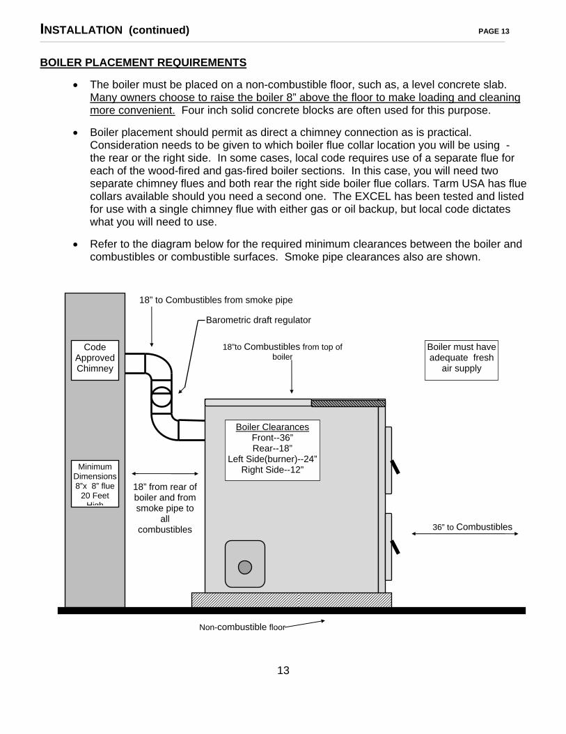
• The boiler must be placed on a non-combustible floor, such as, a level concrete slab. Many owners choose to raise the boiler 8” above the floor to make loading and cleaning more convenient. Four inch solid concrete blocks are often used for this purpose.
• Boiler placement should permit as direct a chimney connection as is practical. Consideration needs to be given to which boiler flue collar location you will be using - the rear or the right side. In some cases, local code requires use of a separate flue for each of the wood-fired and gas-fired boiler sections. In this case, you will need two separate chimney flues and both rear the right side boiler flue collars. Tarm USA has flue collars available should you need a second one. The EXCEL has been tested and listed for use with a single chimney flue with either gas or oil backup, but local code dictates what you will need to use.
• Refer to the diagram below for the required minimum clearances between the boiler and combustibles or combustible surfaces. Smoke pipe clearances also are shown.
13
Code Approved Chimney
Minimum Dimensions 8”x 8” flue
20 Feet High
18” from rear of boiler and from smoke pipe to
all combustibles
Boiler Clearances Front--36” Rear--18”
Left Side(burner)--24”Right Side--12”
Boiler must haveadequate fresh
air supply
18” to Combustibles from smoke pipe
18”to Combustibles from top ofboiler
Barometric draft regulator
36” to Combustibles
Non-combustible floor

INSTALLATION (continued) PAGE 14 __________________________________________________________________________________________________________________________________________________________________________________
BOILER PACKING LIST
NOTE: PLEASE CHECK OFF THE FOLLOWING ITEMS ON THE LISTS BELOW:
• A complete Excel 2000 series boiler, as shipped from our warehouse, consists of five (5) pieces, as follows:
1. BOILER BODY
Ash Removal Pan
Ash Removal/Scraper Tool Cleaning Brush Installation Manual & Warranty Package Box Containing Draft Fan Flue Outlet Turbulators – 6/EXCEL 2000, 8/EXCEL 2200 – should be installed in oil/gas heat exchange tubes 2. JACKET BOX One (1) Front Panel Four (4) Side Panels (2 left & 2 right) One (1) Rear Panel Two (2) Top Panels (front & rear)
Six (6) Pieces Steel Zip Strips 3. DOOR BOX Loading Door Ash Door (with viewing port) By-Pass Lever Bakelite Knob (larger) Secondary Air Bakelite Knob (smaller) Plastic Bag Containing Eight (8) Door Mounting Bolts Bakelite Handles for Doors (2) One (1) Can of Door Mounting Cement and Applicator (Stovex) 4. SAFETY CONTROL PACKAGE Boiler Pressure Relief Valve (#10-102-05, 30 psi) Boiler Control Panel with Pre-Wired Honeywell Controls Draft Fan Low Temp Cut-Off Control Two (2) Pieces Immersion Well, 3/4 inch Pressure/Temperature Gauge Coil Pressure Relief Valve (#17-402-02, 100psi)(optional) 5. BURNER BOX Oil Burner For EXCEL 2000 includes I GPH nozzle – For EXCEL 2200 includes 1.25 GPH nozzle Or and F-6 Retention Head. Gas Burner Includes a duel acting Draft Regulator and a Manual Re-set spill switch.
• Please contact your dealer immediately if any of the above items are missing! • TARM USA, INC. reserves the right to substitute equivalent equipment for any of the
controls and accessories specified above.
14

INSTALLATION (continued) PAGE 15 ___________________________________________________________________________________________________________________________________________________________________________________
BOILER SET-UP
Initial Assembly
1. Unpack the items in the boiler body, door box and jacket box and check off the items enclosed against the packing list on page 14. Be sure to inspect all packages for damage from shipping. All shipping damage claims must be made with the carrier at the time of delivery.
2. Place the boiler in its planned location on a non-combustible floor and positioned for the proper chimney connection. The guidelines on pages 11, 12 and 13 of this manual should be observed!
3. Using the leveling bolts located on each corner of the base, level the boiler both front to rear and side to side.
4. Remove the sheet metal retainer plate from the lower door opening. Save the two bolts to use when attaching the burner. Inspect the refractory chamber bricks for damage or cracks. Check the bottom refractory combustion tunnel brick push it fully to the rear if it has shifted during shipping. There is no need to remove the large rectangular brick in the lower door, unless you believe there is damage to the refractory. If you remove the rectangular brick, be careful not to damage the donut gaskets on top.
5. Locate the secondary air adjustment lever at top left corner of lower door opening and fold it out so it will protrude through the jacket opening when the jacket is assembled.
6. It is not necessary to remove the wooden shipping braces on the boiler floor. They will burn up within a few hours of initial firing.
7. Install the Domestic Hot Water Coil if used. (optional)
Jacket and Door Assembly
NOTE: Prior to jacket installation, remove the appropriate jacket knockouts and plug any extra tappings (see tapping diagram on page 9).
NOTE: The boiler comes with an eight-piece enameled jacket. The sides of the jacket are assembled by sliding the pre-formed steel strips down over the folded, vertical edges of the panels. For installations with low ceiling clearance, the jacket zip strips can be conveniently bent at the center point.
NOTE: The boiler body, front jacket panel and the door frames form a three(3) layer sandwich in final assembly.
NOTE: Before mounting the doors, for ease of handling, separate the doors from the door frames by pulling the hinge pins. Make sure to keep the doors and frames matched. The doors hinge to the right and the bottom door has the observation port.
1. Locate and position the secondary air control lever so that it will protrude through the cut-out in the front jacket panel.
2. Install the two 3/4 inch control wells into the 3/4 inch tappings (#10 and #11) on the side
of the boiler. Use 5 turns of teflon tape to seal the fittings correctly.
15

INSTALLATION (continued) PAGE 16 ___________________________________________________________________________________________________________________________________________________________________________________ Jacket and Door Assembly (continued)
3. Install the left front jacket panel into place (oil burner side). Attach to front panel,
using one (1) zip strip. Engage jacket with bracket on boiler base. 4. Install the left rear jacket panel using the following sequence:
a. Remove the four nuts and burner plate from the rear left side of boiler, b. Install one door mounting gasket over the burner flange, c. Place the left rear side panel into position and slide zip strip to fasten it to left front
panel. Engage the jacket panel with the bracket on the boiler base. d. Place another door mounting gasket over the jacket (at burner flange), and e. Re-install burner plate using four nuts--Hand tighten only.
5. Install right front jacket panel into place. Remove the access panel for the optional Domestic Coil if it is to be installed. Engage jacket with bracket on boiler base.
6. Install right rear panel.
HINT: Be sure you have the flue outlet in its proper place prior to placing this panel.
NOTE: You may use either the right or the rear flue outlet, if you need separate flue outlets for each fuel, contact Tarm USA, Inc.
7. Install rear jacket panel. Prior to placing this panel, remove the plug in tapping #4 if you
are using it as your drain/feed.
HINT: Heating the plug prior to attempting to remove it will make the job much easier. 8. Install top front and rear panels by putting into place and pressing downward.
9. Seal the door frames to the face of the boiler with Stovex or furnace cement using the following procedure:
a. After thoroughly mixing the Stovex compound, place a bead of Stovex on the boiler flanges and the doorframes. Install the front jacket panel. Mount the doorframes in place by just catching the threads, leaving the door loose.
b. From inside the door opening force additional Stovex into the space between the doorframes and the boiler.
c. Check for proper jacket alignment as you tighten the studs evenly. Excess Stovex will be squeezed out leaving a perfect seal at the doors. Immediately wipe excess cement from the jacket with a damp rag.
10. Attach the doors to the door frames by inserting the hinge pins. Install the round bakelite
knob on the secondary air control lever. 11. Tighten nuts on burner mounting plate (left side of boiler).
16

INSTALLATION (continued) PAGE 17 _____________________________________________________________________________________________________________________________________________________________________________________
Jacket and Door Assembly (continued)
Your jacket and doors are now fully assembled!
NOTE: LOADING DOOR SMOKE FLAP. Tarm USA, Inc. recommends that the heavy “C” shaped smoke flap not be permanently installed in the door opening: Doing so may damage the door over time. If you have smoke spillage when loading wood, place the smoke flap in the door opening and remove it before closing the door. If your boiler is installed with a Heat Storage System, you may be able to mount the smoke flap permanently without problems. However, do not allow creosote build-up to occur on the load door behind the smoke flap.
17
INSTALLATION (continued) PAGE 18 _______________________________________________________________________________________________________________________________________________________________________________________
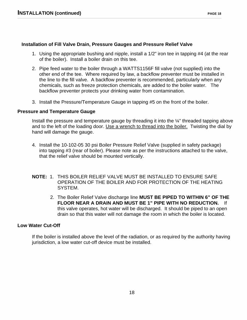
Installation of Fill Valve Drain, Pressure Gauges and Pressure Relief Valve 1. Using the appropriate bushing and nipple, install a 1/2” iron tee in tapping #4 (at the rear
of the boiler). Install a boiler drain on this tee.
2. Pipe feed water to the boiler through a WATTS1156F fill valve (not supplied) into the other end of the tee. Where required by law, a backflow preventer must be installed in the line to the fill valve. A backflow preventer is recommended, particularly when any chemicals, such as freeze protection chemicals, are added to the boiler water. The backflow preventer protects your drinking water from contamination.
3. Install the Pressure/Temperature Gauge in tapping #5 on the front of the boiler.
Pressure and Temperature Gauge Install the pressure and temperature gauge by threading it into the ¼” threaded tapping above and to the left of the loading door. Use a wrench to thread into the boiler. Twisting the dial by
hand will damage the gauge.
4. Install the 10-102-05 30 psi Boiler Pressure Relief Valve (supplied in safety package)
into tapping #3 (rear of boiler). Please note as per the instructions attached to the valve, that the relief valve should be mounted vertically.
NOTE: 1. THIS BOILER RELIEF VALVE MUST BE INSTALLED TO ENSURE SAFE OPERATION OF THE BOILER AND FOR PROTECTION OF THE HEATING SYSTEM.
2. The Boiler Relief Valve discharge line MUST BE PIPED TO WITHIN 6” OF THE FLOOR NEAR A DRAIN AND MUST BE 1” PIPE WITH NO REDUCTION. If this valve operates, hot water will be discharged. It should be piped to an open drain so that this water will not damage the room in which the boiler is located.
Low Water Cut-Off If the boiler is installed above the level of the radiation, or as required by the authority having jurisdiction, a low water cut-off device must be installed.
18

INSTALLATION (continued) PAGE 19 _____________________________________________________________________________________________________________________________________________________________________________________
View of Boiler Piping (Includes Domestic Hot Water Coil)
19

INSTALLATION (continued) PAGE 20 __________________________________________________________________________________________________________________________________________________________________________________
Installation of Domestic Hot Water Coil A tankless coil for heating domestic hot water is available as a factory installed option with the
Tarm EXCEL boilers, or it may easily be added after the boiler is already installed. For ready access to the coil, the cover plate on the jacket is removable.
NOTE: In certain areas, existing water supplies may have a high mineral content. This will lead to liming of the coil over time, depending on the mineral content of the water, the amount of water passing through the coil, and the boiler temperature. If the boiler temperature can be kept under 160°F the buildup in the coils will be much less. Coils should be cleaned as soon as there is any indication that the hot water supply is being restricted. Coils are cleaned with hydrochloric acid-- CLEANING THE COIL IS A DANGEROUS PROCEDURE THAT SHOULD BE ATTEMPTED ONLY BY A QUALIFIED AND EXPERIENCED TECHNICIAN.
1. Pipe the cold water to tapping #12, and hot water from tapping #13 (or vice versa). It is
desirable to install unions external to the boiler in both the cold and hot water lines. NOTE: If a separate hot water heater will be used to heat domestic water during the
warmer months, cold water must be piped separately to the separate water heater, not through the coil in the TARM boiler. COLD WATER MUST NOT FLOW THROUGH THE TARM DOMESTIC COIL IF THE TARM BOILER IS UNHEATED! CONDENSATION AND CORROSION OF THE BOILER BODY CAN RESULT IF WATER FLOWS THROUGH THE COIL OF AN UNHEATED BOILER.
2. Install the Coil Pressure Relief Valve (#17-402-02, 100PSI) in a tee on the cold water
supply to the tankless coil with the relief valve mounted vertically. There must be no shut-off valve or check valve between the coil relief valve and the tankless coil.
WARNING: The Coil Relief Valve discharge line MUST BE PIPED TO WITHIN 6” OF THE FLOOR NEAR A DRAIN AND MUST BE 3/4” PIPE WITH NO REDUCTION. If this valve operates, hot water will be discharged. It should be piped to an open drain so that this water will not damage the room in which the boiler is located.
3. Install a tempering valve (Watts model #70A, or equivalent) and an anti-scald device in
the domestic hot water line out from the coil.
WARNING: A TEMPERING VALVE MUST BE INSTALLED TO PROTECT AGAINST DANGEROUSLY HIGH DOMESTIC WATER TEMPERATURES AND TO PREVENT THE POSSIBILITY OF A PERSON SUSTAINING SERIOUS BURNS FROM DOMESTIC HOT WATER.
20
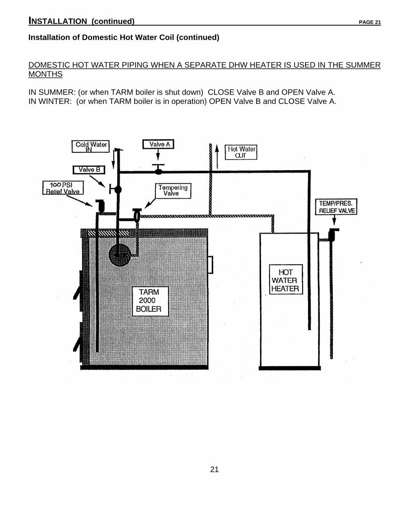
INSTALLATION (continued) PAGE 21 Installation of Domestic Hot Water Coil (continued) DOMESTIC HOT WATER PIPING WHEN A SEPARATE DHW HEATER IS USED IN THE SUMMER MONTHS IN SUMMER: (or when TARM boiler is shut down) CLOSE Valve B and OPEN Valve A. IN WINTER: (or when TARM boiler is in operation) OPEN Valve B and CLOSE Valve A.
21

INSTALLATION (continued) PAGE 22 __________________________________________________________________________________________ _
Control Panel and Fan Assembly
1. Align the control panel with the four small holes in the left front jacket panel. Using sheet metal screws, attach the control panel to the jacket. Insert the capillary tubes (on Honeywell controls) into the two 3/4 inch wells previously threaded into the control tappings #10 and #11. Fasten the Honeywell controls to the well using the screw clamp on the aquastats. NOTE: You may receive 2 - 3/4” x ½” bushings and 2 – ½” wells in place of the ¾” wells.
2. Remove top front jacket panel. On the EXCEL 2000 model boiler, plug or install “coin” air vents in tappings #14 and #15 on top of boiler. On the EXCEL 2200 model boiler, install a “COIN” style air vent in tapping #15 and a vent or plug in tapping #14.
3. Place the 2” thick insulation material (often shipped in the front top jacket panel or found in the jacket box) on top of the boiler, matching the cutouts with the tappings.
4. Remove the metal bracket protecting the adjusting screw and the draft blower fan flange. Using the same screws, attach the draft fan to the flange. Refer to the cut-away boiler diagram on page 8 for proper fan orientation.
Refer to the wiring diagrams on pages 24 - 25 to proceed.
5. Wire the fan to the control panel. Route the fan wires across the insulation on top of the boiler, under the by-pass damper rod, and through the hole in the left side jacket panel. Connect the brown wire from the fan to the “F” (HOT) terminal, the blue fan wire to the “N” (NEUTRAL) terminal and the yellow and green stripe fan wire to the “G” (GROUND) terminal on the 120volt terminal strip inside the control panel.
6. Mounting the Draft fan low temperature Flue Gas Sensor
a. Mount the junction box to the left of the control panel. Make sure you have enough cable to make the connections to the S1 and S2 terminals inside the control panel.
b. Drill a ¼” hole in the top of the smoke pipe within 6” of the boiler flue collar.
c. Insert the sensing bulb fully into the smoke pipe. Be careful not to kink the capillary tube! Fasten the capillary tube so that the sensing bulb is held in position.
NOTE: • ALL CONNECTIONS ON THE 120 VOLT TERMINAL STRIP INSIDE THE CONTROL PANEL HOUSING ARE 120 VOLT.
• ALL CONNECTIONS ON THE EXTERNAL 24 VOLT TERMINAL STRIP ON THE OUTSIDE LEFT OF THE CONTROL PANEL HOUSING ARE 24 VOLT.
120 Volt Connections To House, Burner and Circulator
All wiring must be completed as per the wiring diagrams on pages 24 - 25.
NOTE: 1. ALL WIRING MUST BE INSTALLED IN ACCORDANCE WITH NFPA STANDARD #70 AND THE NATIONAL ELECTRICAL CODE.
2. The electrical system of the boiler shall be supplied from a single branch circuit.
3. The boiler itself must be grounded in accordance with the requirements of the authority with jurisdiction, or, in absence of such authority, in accordance with the National Code, ANSI/NFPA #70-1978.
22

INSTALLATION (continued) PAGE 23 __________________________________________________________________________________________________________________________________________________________________________________
CONTROL PANEL AND WIRING LAYOUT
23
Intentionally left blank__________________________________________________________

FIELD WIRING DIAGRAMS PAGE 24

24
WIRING SCHEMATIC FOR CONTROLS PAGE 25

This is an insert page.
25

HS-TARM EXCEL CONTROLS OPERATION SEQUENCE Rev. 4/25/03 1 MECHANICAL SETUP The Tarm EXCEL boiler is a wood-fired boiler with oil or gas backup
burner. System may be installed with an optional heat storage tank (HST)
1.1 120 volt backup burner (oil or gas) with TT terminals for control. 1.2 120 volt forced draft fan provides combustion air. 1.3 When circulator “C-3” turns on, it circulates water through the boiler while it is warming. As
THERMOVAR tempering valve opens, it circulates water to the heat storage tank (or to heating loops if circulator C-1 or other heating loop circulator(s) is running). For systems with no HST, circulator “C-3” runs only if a heating loop is calling for heat.
1.4 Circulator “C-1” circulates water through the heating loops. 2 CONTROLS EXTERNAL TO THE PANEL 2.1 Emergency cut-off switch de-energizes panel. 2.2 Fire-o-matic thermal sensor de-energizes panel. 2.3 Smoke temperature sensor senses stack temperature. 2.4 In optional HST, Honeywell L8151A aquastat senses tank temperature, LO set at 150°F starts backup burner when no wood fire is burning. HI set at 160°F stops backup burner. 2.5 Honeywell L8124C aquastat controls system functions. LO set at 210°F controls overheat functions, HI set at 180°F is the operating temperature for all modes. 2.6 Honeywell L6081A aquastat controls system functions. LO set at 165°F. For HST systems this starts circulator “C-3” when boiler temperature is up to this setting. HI set at 200°F provides high back up temperature limit for all modes. 2.7 In all aquastats, DIFF (set at 10°F) is the operating differential for LO. The operating differential for HI is fixed at 10°F. 3 CONTROLS IN THE PANEL 3.1 Top switch provides on/off control and resets the automatic backup mode. 3.2 Bottom switch is the mode selector switch. 3.2.1 Auto backup. 3.2.2 Wood only. 3.2.3 Backup only. 3.3 Five minute timer for draft fan override. 3.4 Relay CR1 provides overheat control. 3.5 Relay CR2 provides lock-off draft fan when fire goes out. 3.6 Adjustable time delay allows time for stack to warm up at start up. (Section 4 below assumes the
typical setting of approx. 15 minutes). 3.7 Relay CR3 control the backup burner. 3.8 Transformer provides 24 VAC power. 4 OPERATION SEQUENCE AND TECHNICAL INFORMATION
Refer to wiring schematic and field wiring diagram for specific plumbing plan. System may be operated one of three modes as selected by the mode selector.
4.1 Auto backup mode. This description assumes a cold startup with a wood fire starting to burn. 4.1.3 Draft fan operates as follows. Power passes through the on/off switch, the L8124C LO (which opens during overheat), the L8124C HI (which opens when operating temperature is achieved), the L6081A HI (which is set higher than the L8124C HI and opens as backup high limit), and a N.C. (normally closed) contact 8-2 on CR2 (which opens for auto backup function, “fire out,” or if system is set to backup burner) to terminal F for the 120V draft fan.
26

4.1.2 Warmup cycle. Power passes from the L8124C (as above) through a N.C. contact 11-3 on CR3(which opens when backup burner is running), through the smoke temperature sensor(which opens when stack achieves temperature setting), to the time delay module. If stack temperature is achieved in less than 15 minutes, smoke sensor opens, this timer will stop timing and draft fan will continue operating. If at any time after L8124C HI (operating temperature) is closed, the smoke temperature sensor stays closed due to the stack not warming for more than 15 minutes, this delay will activate and turn on relay CR2 which locks on.
4.1.3 Automatic backup function. Draft fan operates controlled by the L8124C HI (operating temperature) until fire is out and stack temperature is below sensor setting for 15 minutes. Then draft fan stops and backup burner operates. Once relay CR2 is activated, CR2 N.O. (normally open) contact 7-4 closes to lock relay CR2 on which may be reset by turning off the on/off/reset switch. CR2 N.C. contact 8-2 opens, stopping the draft fan. CR2 N.O. contact 9-6 closes. For systems with no HST, relay CR3 turns on immediately. For HST systems, if the L8151A LO is closed(HI will be closed),relay CR3 energizes. CR3 N.O. contact 10-6 closes to lock on CR3 until HI temperature has been achieved. The L8151A continues to maintain storage tank temperature between HI and LO settings. CR3 N.O. contact 9-5 closes to activate the backup burner by shorting TT. Although this contact controls the burner, the actual power for the burner passes through the two aquastats just as it does for the draft fan. For HST systems, CR3 N.O. contact 8-12 closes to allow circulator “C-3” to run while burner is running. CR2 N.C. contact 1- 7 opened this circuit. After system, is in back-up mode, the C-3 circulator should only run while the burner is running to prevent circulation of warm water from the heat storage tank to the boiler. CR3 N.C. 11-3 opens while backup burner is running to prevent a “hot” back feed through the smoke temperature sensor to the orange wire which is controlled by the L8124C.
4.2 Wood only mode. This mode operates similarly to the auto backup mode. The basic difference is that when the draft fan stops, the backup burner does not start. There are no changes for the items discussed in 4.1.1 and 4.1.2 above. Once relay CR2 is activated, CR2 N.O. contact 7-4 closes to lock relay CR2 on which may be reset by turning off the on/off/reset switch. CR2 N.C. contact 8-2 opens, stopping the draft fan. For HST systems. CR2 N.C. contact 7-1 opens to stop circulator “C-3.” This prevents the circulation of warm water from the heat storage tank to the boiler. Although CR2 N.O. contact 9-6 closes, the mode selector switch prevents CR3 from energizing.
4.3 Backup mode only. In this mode, the backup burner operates and the draft fan does not. The mode selector switch directly energizes relay CR2. The details of operation are basically the same as what is given under automatic backup function (4.1.3) above. The smoke sensor does not provide any control function in this mode.
4.4 Overheat function. Since an active wood fire cannot easily be “stopped” boiler overheating can occur. If boiler temperature rises in spite of the draft fan not running (L8124C HI and L6081A HI are open), L8124C LO (set at 210°F) close on rise contact R-W will close, energizing relay CR1. For HST systems, CR1 N.O. contact 5-3 closes to start circulator “C-3” if for any reason it is not running. CR1 N.O. contact 6-5 closes to override heat dump zone room thermostat and thereby take excess heat from the boiler.
4.5 Draft fan timer. Because of the potential for explosion, the doors accessing the firebox should never be opened while the draft fan is not running. The operator may turn on the draft fan override timer. This causes the draft fan to operate even though the L8124C HI is open.
4.6 Circulator “C-1” control. In the L8124C, the relay 1-K is available for control of circulator “C-1” or a heating zone circulator, Whenever the L8124C terminals TT are shorted (as shown on field wiring diagram), relay 1-K energizes. N.O. contact 1-K2 closes to energize the circulator. The fact that the N.O. contact 1-K1 closes and overrides the LO open on rise contact does not present a problem because of the open on rise HI in each of the two aquastats.
27

INSTALLATION (continued) PAGE 28 _____________________________________________________________________________________________________________________________________________________________________________________
By-Pass Damper Adjustment
The by-pass lever is adjusted at the factory, but should be checked, as correct adjustment is essential for proper combustion. To check adjustment, push the by-pass knob in and down. With a firm push, it should lock into place on the bracket. If the stop on the rod is engaged on the bracket but the handle still has front to back play, or, if the handle will not push in far enough to engage the stop, the by-pass must be adjusted. To do so, loosen the nut at the rear of the rod and rotate the rod to tighten or loosen the adjustment. To complete the adjustment, make sure the welded stop rod is pointed downward, and tighten the locknut.
Turbulators Turbulators should be located in the oil or gas heat exchange tubes when the boiler is received.
Please check to be sure they are located correctly and that they are not in the wood heat exchange tubes in error.
Installation of Back-Up Fuel Burner
Either an oil, propane gas (LPG) or natural gas (NG) burner may be used to provide back-up or full-time heat with the EXCEL boiler.
Individual instruction manuals are provided in the box with each oil or gas burner. In addition, the following information is necessary and important:
• Before installing the burner, if necessary, trim the hole in the burner door brick with a knife so that the burner can be inserted through the opening.
• 120 Volt AC power feed for the oil or gas burner is wired to “B” and “N” terminals inside the boiler Control Panel. The “T” terminals on the burner primary control must be connected to the #7 and #8 terminals on the 24 Volt terminal strip on the Control Panel housing.
NOTE: 1. IF THE OIL OR GAS BURNER IS IMPROPERLY INSTALLED, NOT INSTALLED AND/OR NOT SERVICED ON A REGULAR BASIS, DAMAGE TO THE BOILER MAY RESULT.
2. BURNER INSPECTION AND TUNE-UP SHOULD BE DONE NOT LESS THAN ONCE PER YEAR BY A QUALIFIED HEATING CONTRACTOR OR BURNER SPECIALIST. DAMAGE TO THE BOILER OR PARTS DUE TO IMPROPER INSTALLATION MAY NOT BE COVERED UNDER WARRANTY!
Oil Burner Installation (refer to Oil Burner Manufacturer’s Instruction Manual)
If the Tarm EXCEL is to be fired on oil, a flame-retention burner MUST be used. A BECKETT AF burner is standard equipment. Oil burners must be adjusted with test equipment, not “by
eye”. A minimum .04 in./wc draft is required. The nozzle specifications are as follows:
•TARM EXCEL 2000 •TARM EXCEL 2200 80 ° Delavan B--- .75 to 1.10 GPH 80° Delavan B--- .75 to 1.35 GPH
NOTE: The Beckett AF burner must be equipped with an F-6 retention head for operation with 1.10GPH or greater nozzle. An F3 head is standard with the burner. An F-6 retention head is shipped with an EXCEL 2200.
28
INSTALLATION (continued) PAGE 29 _____________________________________________________________________________________________________________________________________________________________________________________
Oil Burner Installation (continued)
NOTE: ALL OIL BURNERS MUST BE INSTALLED IN ACCORDANCE WITH NFPA STANDARD #31.
In clean boilers, oil-burning efficiencies of 85%-87% can be expected as measured by stack analysis.
Gas Burner Installation (refer to Gas Burner Manufacturer’s Instruction Manual)
The EXCEL Boilers may be fired on either natural gas or propane fuel. The G2T Gas Burner by Adams have been tested and listed with the EXCEL boilers. Each Adams Burner is shipped with two orifices. The smaller orifice for the EXCEL 2000 should be in place when the burner is received. If you have an EXCEL 2200 you will need to change out the smaller orifice for the larger one as per the instructions on page 13 of the gas burner instruction manual.
•TARM EXCEL 2000 •TARM EXCEL 2200 Maximum Input Orifice Maximum Input Orifice LP Gas = .213 LP Gas = .257 Natural Gas = .260 Natural Gas = .312
NOTE: The installation of all gas burners must conform to the requirements of the authority having jurisdiction, or in the absence of such requirements, to the National Fuel Gas Code, ANSI Z 2231, or CAN/CGA B149 Installation Code.
In clean boilers, gas-burning efficiencies of 82-83% can be expected.
Important Venting Instructions for EXCEL Boilers with Gas Burners
A. MULTI-FUEL VENTING The EXCEL multi-fuel boilers have the option of having two (2) separate flue collars: one for wood burning and one for gas. If 2 flue collars are used, the plate positioned diagonally over the gas heat exchange tubes should be positioned and fixed vertically. Use gasketing to fully seal and separate the wood and gas heat exchange and flue exit areas. A second flue collar can be purchased from Tarm USA, Inc.
B. SINGLE FLUE VENTING The EXCEL multi-fuel boilers have been approved for single flue venting of wood and gas in the same flue. However, a dual acting barometric damper and a spill switch with a manual reset must be utilized. This spill switch is installed to detect flue gas spillage caused by a blocked flue system and/or inadequate draft. This devise MUST be installed by a qualified installer in accordance with the manufacturers’ installation instructions included with the device.
NOTE: THE BOILER SHALL BE INSTALLED SUCH THAT THE GAS IGNITION SYSTEM COMPONENTS ARE PROTECTED FROM WATER (DRIPPING, SPRAYING, RAIN, ETC) DURING APPLIANCE OPERATION AND SERVICE (CIRCULATOR REPLACEMENT, CONTROL REPLACEMENT, ETC.)
LEAK TESTING: The boiler water jacket and gas connection must be leak tested before putting the boiler in operation OVERHEATING: When burning gas, should overheating occur, or the gas supply fail to shut off, do not turn off or disconnect the electrical supply to the pump. Instead, shut off the gas supply at a location external to the appliance.
29

HEAT STORAGE TARM USA recommends that the best installation of all HS-TARM boilers is one that includes a heat storage tank. Until you burn wood in a TARM boiler that is installed with a properly sized heat storage system, you won’t know how easy it can be to heat with wood. By storing boiler heat in an insulated water storage tank you gain increased operating flexibility and you can easily heat at full output with the cleanest and most efficient operation. The Tarm boiler’s heat output is usually greater than the heating requirements of the house. The “extra” heat is transferred to the storage tank for use later. Because of the buffer the heat storage system provides, you are free to fire the boiler when it is convenient for you. On most days in the winter you will only need to load the boiler once in 24 hours. In summer you will be able to go 4-10 days between firings to heat all your domestic hot water. You don’t need to rush home or get up early to load more wood. There are no problems with creosote or overheating if the boiler is oversized. The insulated storage tank absorbs the heat produced at maximum boiler output until the wood is consumed and the boiler shuts off. Heat is recaptured from the storage tank as heat and domestic hot water is needed in the house. How do you add heat storage to your system? The first requirement is to get a tank. We recommend a 600-gallon tank with the Solo Plus 30, MB 40 and EXCEL 2000. Tanks of 800 gallons or more are recommended for the Solo Plus 40, Solo Plus 60, MB55, and MB 75 and the EXCEL 2200. Any suitable insulated water tank may be utilized. However, the system design will determine whether a particular tank is suitable. Three types of systems you may consider are atmospheric, pressurized, or unpressurized. The tank in an atmospheric system will need to be able to withstand the pressure of the water column above the tank. (For information, the pressure on a tank installed in a two-story house with an open expansion tank above will run 10 to 12 pounds.) A large capacity tank that can withstand this pressure will be expensive and in most cases difficult to get into a basement. A pressurized system running at up to 30-lbs. pressure will require a much heavier tank. Tanks of 600-800 gallons designed to take this system pressure and with the ability to accept a domestic hot water heater exchanger will be expensive, hard to handle, and hard to find. In addition, an expansion tank big enough to handle the expansion of this much water will cost as much as the storage tank. Using a vented, unpressurized tank with heat exchangers offers many advantages. Stainless steel or plastic bulk storage tanks can often be found. These tanks will not corrode, and can be insulated once in place. Openings in the tops of these tanks are usually large enough to allow the installation of heat exchange coils. External heat exchangers could also be considered. The size of these tanks also may make it difficult to get them into an existing basement.
TARM USA Inc. has available a collapsible urethane foam tank with an EPDM rubber liner and embossed aluminum outer skin. These tanks range in size from 415 to 1205 gallons, and are shipped in a 19” wide crate and can easily be moved through narrow doors or down stairs. The 48” tank height allows the use of fully immersed vertical heat exchangers, which take full advantage of heat stratification in the tanks. Sven Tjernagel of STSS CO. INC designed this tank and heat exchange system. It is unique and has the capability to be used for space heating, heating domestic hot water, solar heat storage or electric heat storage. There are many way to incorporate heat storage into your system. If correctly installed, you will never regret it. You will get highest efficiency, burn less wood, and have cleaner combustion, longer boiler life and freedom to fire your boiler when it is convenient for you. It doesn’t get any better than this! Please contact us at TARM USA, INC. We will be glad to recommend a heat storage system for your HS-TARM boiler utilizing an STSS system. We provide installation and operational support for the STSS Storage system sold by TARM USA INC. The heat storage systems have separate plumbing and wiring diagrams not covered in this manual.
30

INSTALLATION (continued) PAGE 31
PIPING TO HEAT DISTRIBUTION SYSTEM IN HOME
The Tarm EXCEL may be connected to several different forms of heat distribution within your home, either separately or in combination, as follows:
• Hot Water Baseboard Heating
• Radiant Floor Heating
• Hot Air Heating
Hot Water Baseboard Heating
For specific information, see IBR Bulletin #200, “Residential Hydronic Heating Systems”, which can be obtained from The Hydronics Institute, 35 Russo Place, Berkeley Heights, NJ 07922.
NOTE: OVERHEAT LOOP: The piping and controls must be connected to the boiler in such a way that there is one loop of radiation available for gravity circulation in event of power failure. (See diagram at bottom of page 32). This loop must not be obstructed by any valves or other accessories which would prevent gravity circulation during a power failure. The loop must be large enough to dissipate at least 10% of the boiler’s maximum rated output on solid fuel, assuming an ambient temperature of 65° F in the area heated by the loop, and a water temperature of 180° F.
The minimum pipe size for this loop is 3/4”, and, if possible, the loop should be located and pitched to maximize natural thermal convection of the water. The design of the loop must be such that it can be made inoperative only by deliberate manual action.
If large enough, an existing heating radiation zone may be used for the overheat loop if it is equipped with zone valves which will open automatically during a power failure. (We recommend the use of AUTOMAG automatic zone valves for this application! TARM USA, INC. can supply these valves.) If large enough, a heating zone under circulator control may also provide enough overheat capacity. Please refer to piping layout concept diagram.
The TARM EXCEL piping installation must include an air purger, air vent and expansion tank, as is described below.
• For connection to conventional systems see diagrams on pages 9, & 32, and proceed as follows:
1. Thread a 1 1/4” pipe nipple into tapping #1 (side of boiler). Then install a tee for connection to the zone to be used for gravity circulation to provide overheat protection during a power failure. Next connect an AMTROL #444 (1 1/4”) air purger, or comparable air eliminator, using the inlet tapping. DO NOT REDUCE THE PIPE SIZE UNTIL AFTER THE AIR PURGER AND TEE LEADING TO THE TERMOVAR.
2. An AMTROL #60 or comparable expansion tank should be used. (This tank is sufficient for systems up to 86 gal. capacity. For systems with greater capacity, consult your installer or dealer.)
3. Install a Termovar tempering valve (available from TARM USA, INC.), a balancing valve and a circulator as shown on page 32. Pipe the return into tapping #2, rear of boiler.
NOTE:All Interconnection wiring must be completed as per the wiring diagrams on pages 24-25.
31
INSTALLATION (continued) PAGE 32 ______________________________________________________________________________________________________________________________________________________________________________________
TERMOVAR TEMPERING VALVE
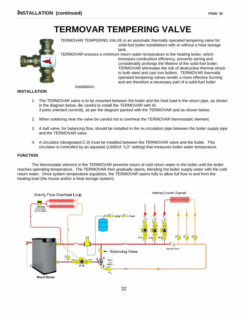
TERMOVAR TEMPERING VALVE is an automatic thermally operated tempering valve for solid-fuel boiler installations with or without a heat storage tank.
TERMOVAR ensures a minimum return water temperature to the heating boiler, which increases combustion efficiency, prevents tarring and considerably prolongs the lifetime of the solid-fuel boiler. TERMOVAR eliminates the risk of destructive thermal shock to both steel and cast iron boilers. TERMOVAR thermally operated tempering valves render a more effective burning and are therefore a necessary part of a solid-fuel boiler
installation. INSTALLATION
1. The TERMOVAR valve is to be mounted between the boiler and the heat load in the return pipe, as shown in the diagram below. Be careful to install the TERMOVAR with its 3 ports oriented correctly, as per the diagram packed with the TERMOVAR and as shown below.
2. When soldering near the valve be careful not to overheat the TERMOVAR thermostatic element. 3. A ball valve, for balancing flow, should be installed in the re-circulation pipe between the boiler supply pipe
and the TERMOVAR valve. 4. A circulator (designated C-3) must be installed between the TERMOVAR valve and the boiler. This
circulator is controlled by an aquastat (L6081A “LO” setting) that measures boiler water temperature. FUNCTION The thermostatic element in the TERMOVAR prevents return of cold return water to the boiler until the boiler reaches operating temperature. The TERMOVAR then gradually opens, blending hot boiler supply water with the cold return water. Once system temperature equalizes, the TERMOVAR opens fully to allow full flow to and from the heating load (the house and/or a heat storage system).
32

INSTALLATION (continued) PAGE 33 ______________________________________________________________________________________________________________________________________________________________________________________
PIPING TO HEAT DISTRIBUTION IN HOME (continued)
Radiant Floor Heating An increasing number of HS-Tarm boilers are being installed with radiant floor heating systems.
Your heating system installer and/or your radiant floor equipment supplier will supply needed design and installation details.
Hot Air Heating Boilers can be used in a number of ways to provide hot air heating. This can be done with
existing forced hot air heating systems and in new construction. Again, your system installer and/or your equipment supplier should supply the needed design and installation details.
FILLING YOUR BOILER Fill your Tarm EXCEL boiler and heating system in the conventional manner.
NOTE: The boiler may be protected with antifreeze. It should be propylene glycol and should be checked annually for proper freeze protection and P.H. level. HOWEVER, please remember that the domestic hot water coil, if you have one, is not protected by the antifreeze. Also, please be aware that the use of antifreeze in your system may decrease heat exchange efficiency 5-10%.
33

OPERATING YOUR BOILER PAGE 34 ______________________________________________________________________________________________________________________________________________________________________________________
OPERATIONAL OVERVIEW As previously stated, the TARM EXCEL boiler may be used either with or without a heat storage system. This boiler may also be fired on wood only, be operated with automatic switchover to the oil (or gas) burner if it runs out of wood and starts to lose temperature, or it may be fired on oil (or gas) only. This operational flexibility results in numerous possible operating scenarios which will call for different aquastat control settings to be used. The aquastat control settings recommended, on pages 35 and 50, are given as a starting point. The boiler operator may find, with experience that these settings can be modified somewhat to optimize boiler and heating system performance. Please contact us at TARM USA, INC. if you have questions or concerns after you have your boiler in operation.
BEFORE YOU BEGIN SAFETY NOTICE: READ THIS ENTIRE MANUAL BEFORE YOU INSTALL AND
OPERATE YOUR NEW BOILER. FAILURE TO FOLLOW THE INSTRUCTIONS MAY RESULT IN PROPERTY DAMAGE OR
BODILY INJURY.
To operate your boiler in disregard of the information provided in this section can cause permanent damage to your boiler and void your warranty.
WARNING: NEVER USE GASOLINE, KEROSENE OR OTHER FLAMMABLE LIQUIDS
TO START OR MAINTAIN SOLID-FUEL FIRES IN YOUR BOILER -- SERIOUS BURNS OR PROPERTY DAMAGE MAY RESULT!
NOTE: Do not be alarmed if you smell an unusual odor the first few times you fire the
boiler. This smell is due to burning of oil residues in the paint on the boiler and the smoke pipe. Ventilate the boiler room well for the first few hours during the first fire.
LOW TEMPERATURE FLUE GAS SENSOR AND TIME DELAY MODULE The low temperature flue gas sensor and the time delay module work together to shut off the wood combustion draft fan after a load of wood fuel has been consumed so that the fan won’t continue to run unnecessarily. If the draft fan continued to run after the boiler ran out of wood fuel it would waste electric energy and cool the boiler. The flue gas temperature sensor should be set at approximately 120°C initially. This setting may need to be adjusted somewhat, higher or lower, to optimize performance and to leave enough charcoal to easily start your next fire. The time delay module should be set at 15 minutes. This setting also may need to be adjusted somewhat to optimize performance. When the boiler is set in the “AUTO BACK-UP” mode, the oil or gas burner will automatically be switched on if the flue gas temperature sensor and time delay module shut off the wood draft fan.
34

OPERATING YOUR BOILER (continued) PAGE 35 _____________________________________________________________________________________________________________________________________________________________________________________
AQUASTAT CONTROL SETTINGS DURING WINTER (HEATING SEASON) Before you start your boiler make certain the aquastats are set as follows:
Honeywell L8124C (on boiler)
Scale Setting Function
LO 210 ° F Boiler Overheat... starts Circulator C-3 and overrides room thermostat for “dump zone” to dissipate excess heat
HI 180 ° F Boiler Operating temperature for all Modes DIFF 10 ° F Operating Differential
Honeywell L6081A (on boiler)
Scale Setting Function LO 165 ° F Temperature setting at which Circulator C-3 starts operating HI 200 ° F Backup high temperature limit for all modes DIFF 10 ° F Operating Differential
Honeywell L8151A (on optional heat storage tank) Scale Setting Function
LO 150 ° F Temperature setting at which oil or gas burner starts again after heat storage tank has been heated up to “HI” setting on L8151A and then cooled down.
HI 160 ° F Heat Storage Tank Operating Temperature when being heated by oil or gas burner when the boiler is in either the “BACK-UP ONLY” or the “AUTO BACK-UP” operating mode.
DIFF 10 ° F Operating Differential NOTE: When a heat storage tank system is not being used the Honeywell L8151A aquastat
will not be used. A jumper wire must be installed between Terminal 1 and Terminal 3 on the boiler control panel’s External 24 Volt Terminal Strip (refer to “Field Wiring Diagrams” on page 24 and 24.1).
35

OPERATING YOUR BOILER (continued) PAGE 36 ______________________________________________________________________________________________________________________________________________________________________________________
MODES OF OPERATION The Tarm EXCEL boiler can be operated in three different modes:
• Wood burning only (switch position “WOOD ONLY”) • Oil or Gas burning only (switch position “BACK-UP ONLY”) • Wood burning with automatic back-up (switch position “AUTO BACK-UP”)
The settings and explanation for each mode follows:
• WOOD BURNING ONLY (“WOOD ONLY”)
When set to this mode, the draft fan for wood combustion will run to attempt to keep the boiler at 180° (best operating temperature). There are several conditions which will cause the wood combustion draft fan to shut off after the boiler has been turned on in the “WOOD ONLY” mode. The draft fan will turn off if:
1. The main control panel power switch is turned off, or,
2. The boiler achieves the 180°F Operating Temperature (which trips the L8124C “HI” control),or,
3. The Smoke Temperature Sensor setting isn’t achieved before the Time Delay Module
time setting “times-out” cutting power to the fan (This will happen anytime the boiler runs out of wood fuel or anytime the wood fire is not hot enough to create a high enough temperature to activate the Smoke Temperature Sensor.), or, if,
4. The boiler overheats (which trips the L6081A “HI” control). In summary, as long as there is a sufficient quantity of good quality fire wood in the
boiler it should maintain Operating Temperature (170°F to 180°F).
• OIL OR GAS BURNING ONLY (“BACK-UP ONLY”)
When no heat storage tank is used and when the boiler control is set to this mode, “BACK-UP ONLY”, the oil or gas burner will fire to keep the boiler at Operating Temperature (170°F to 180°F). When a heat storage tank is used the burner will also be responding to the settings on the L8151A aquastat located on the tank, i.e., once the heat storage tank gets up to 175°F (L8151A “HI” setting) the burner will not fire again until the tank cools back down to 155°F (L8151A “LO” setting minus the 10° F differential).
36

OPERATING YOUR BOILER (continued) PAGE 37 ______________________________________________________________________________________________________________________________________________________________________________________
MODES OF OPERATION (continued)
• WOOD BURNING WITH AUTOMATIC BACK-UP (“AUTO BACK-UP”) When set to this mode, “AUTO BACK-UP”, (or after reset), the control logic is as follows:
When starting a cold boiler, the wood combustion draft fan will run until the wood fire
causes the boiler water to attain a temperature of 180° F (L8124C “HI” setting). The fan will then cycle off and on trying to maintain boiler temperature (170° F to 180°F). Should the wood fire die out and, therefore, not make enough heat, then the wood draft fan will stop (as in item “3” under “WOOD BURNING ONLY” on page 34 and 36) and the oil or gas burner will turn on. The oil or gas burner will then bring the boiler temperature back up to 180° F. When no heat storage tank is used and when the boiler control is set to the “AUTO BACK-UP” mode, the oil or gas burner will fire to keep the boiler at Operating Temperature (170°F to 180°F). When a heat storage tank is used the burner will also be responding to the settings on the L8151A aquastat located on the tank, i.e., once the heat storage tank gets up to 175°F (L8151A “HI” setting) the burner will not fire again until the tank cools back down to 155°F (L8151A “LO” setting minus the 10° F. differential). The wood combustion draft fan will remain off until reset. To reset, switch the boiler Control Panel power switch to the position “OFF/RESET” and then back to “ON”. A power failure will also reset this control.
USE OF THE BY-PASS DAMPER
The by-pass damper must always be opened before opening the loading door. This will minimize smoking and puff-backs. The by-pass should always be locked tightly in the closed position when the boiler is in operation. Failure to close the by-pass damper tightly may lead to puffing and incomplete combustion!
INSTALLING THE 339N PROBE THERMOMETER The 339N Probe Thermometer is to be installed just downstream of the boiler flue collar. Drill a
¼” hole in the top of the pipe and insert the probe all the way in. The thermometer gives you an indication of how well the wood is burning and when it is time to brush the heat exchange tubes. If you are burning dry wood that is well split, you should achieve temperatures of 600°F or more on the probe thermometer. If you are not achieving temperatures this high, check the following things:
1. Is the by-pass damper latched tightly closed?
2. Are the vanes of the fan clean and not filled with ash?
3. Are the primary air channels open?
4. Is your wood dry?
In most instances, low stack temperatures are an indication of wood that is not dry. If you have
been operating with temperatures of 600°F and then notice the temperatures are higher, it is probably an indication that it is time to brush the dust from the heat exchange tubes.
37

OPERATING YOUR BOILER PAGE 38
A WORD ABOUT WOOD FUEL Wood is an environmentally desirable fuel as it is CO2 neutral.
Your Tarm EXCEL boiler is designed to burn natural cord wood with high efficiency and low emissions. With properly dried and prepared wood you will fully realize the best operating, heating and clean-burning potential of your boiler. If you use poor wood, your EXCEL will be much less efficient and produce less heat. Dry wood gives big returns!
• Log length should be approximately 18” to 20”. Firebox length is 21 ½”. • Pieces over 5” in diameter should be split. • Moisture content of 15% to 20% is best.
To promote faster drying of firewood, it should be cut to length, split and stacked loosely off the
ground, with maximum exposure to the sun and the wind so that air can circulate through the stack. Cover only the top of the stack (at an angle to allow moisture to run off) to keep out rain and snow. Always try to have two years supply on hand so that the wood you are burning has been cut, split, and stacked under cover for a year. Some varieties of wood may take 1 ½ years to dry adequately. If you cut your trees in the spring or summer, let them lie for a while until the leave wither. They will draw moisture from the wood more quickly than if you limbed the trees immediately. If you buy your firewood, spring or early summer is usually the best time to purchase it. You get roughly the same amount of heat from a pound of wood, no matter what species of tree it comes from. But wood is not sold by the pound; it is sold by volume – by the cord. Therefore, the dense, heavy woods are the best to buy because they will give you more pounds per cord.
WARNING: DO NOT BURN PAINTED, CREOSOTED OR PRESSURE TREATED WOOD.
WARNING: DO NOT USE SAWDUST, WOOD PELLETS OR SCRAPS OF WOOD SO SMALL THAT THEY CAN FALL THROUGH THE SLOT BEFORE BURNING OR PLUG THE SLOTS SO THAT BURNING CEASES.
WARNING: COAL CANNOT BE USED IN YOUR TARM EXCEL BOILER. Coal will damage the refractory in the firebox.
38
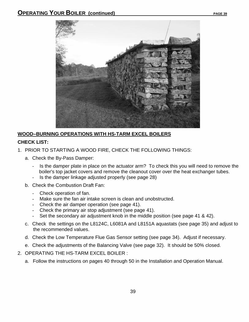
OPERATING YOUR BOILER (continued) PAGE 39 WOOD–BURNING OPERATIONS WITH HS-TARM EXCEL BOILERS
CHECK LIST:
1. PRIOR TO STARTING A WOOD FIRE, CHECK THE FOLLOWING THINGS:
a. Check the By-Pass Damper:
- Is the damper plate in place on the actuator arm? To check this you will need to remove the boiler's top jacket covers and remove the cleanout cover over the heat exchanger tubes. - Is the damper linkage adjusted properly (see page 28)
b. Check the Combustion Draft Fan:
- Check operation of fan. - Make sure the fan air intake screen is clean and unobstructed. - Check the air damper operation (see page 41). - Check the primary air stop adjustment (see page 41). - Set the secondary air adjustment knob in the middle position (see page 41 & 42).
c. Check the settings on the L8124C, L6081A and L8151A aquastats (see page 35) and adjust to the recommended values.
d. Check the Low Temperature Flue Gas Sensor setting (see page 34). Adjust if necessary.
e. Check the adjustments of the Balancing Valve (see page 32). It should be 50% closed.
2. OPERATING THE HS-TARM EXCEL BOILER :
a. Follow the instructions on pages 40 through 50 in the Installation and Operation Manual.
39

OPERATING YOUR BOILER (continued) PAGE 40
STARTING YOUR TARM EXCEL BOILER Before starting your boiler for the first time the installer must check that it is properly filled with
water and vented of air. It is also important to vent the boiler again after the boiler is up to the 180° F operating temperature. It is important also that the installer check all the control functions and settings and set up the burner before leaving the boiler unattended. Check the operating, low temp. cut out, overheat, burner cut in and out, and reset functions. It is recommended that you bring the boiler up to a temperature of 160° F with your back-up oil or gas burner before starting a solid fuel fire. This is an ideal time to fine tune the burner and set it up for peak operational efficiency, as well as to check control settings and functions.
Lighting the Boiler for the First Time Starting Your Tarm EXCEL boiler on wood for the first time, or, if the fire is out.
NOTE: THE WOODEN SHIPPING BOARDS HOLDING THE REFRACTORY IN PLACE WILL BURN UP. DO NOT TRY TO REMOVE THEM!
1. Set the by-pass damper lever in the open position by pulling the knob up and fully out. 2. Position the operation mode switch to wood burning only (“WOOD ONLY”) or wood
burning with automatic backup (“AUTO BACK-UP”). 3. Turn the control panel power switch to “OFF/RESET”. 4. Open the loading door and line the bottom of the firebox with several pieces of crumpled
newspaper. Place several pieces of kindling and small pieces of wood on top of the paper.
5. Place 6 or 8 more crumpled sheets of paper on top of kindling. Light the paper and
close the door. 6. Immediately turn the power switch to “ON” to start the wood combustion draft fan. 7. After 3-4 minutes, turn “OFF” the power switch. Immediately open the upper door slowly
and carefully to see that the fire is established. If it is, add several more small pieces of firewood. Close the upper door.
8. Immediately turn “ON” the power switch to start the draft fan. Close and latch the by-
pass by pushing in and down to lock it shut.
9. Wait approximately 5 more minutes, then look through the sight glass in the ash door. You should see a full active flame filling the combustion tunnel. If not, give the fire a few more minutes before loading with larger fuel. When loading wood it should be placed close together and uniformly front to back and not crosswise.
Depending on the dryness and size of your firewood you may be able to skip step #9
and fully load the boiler in step 7.
40

OPERATING YOUR BOILER (continued) PAGE 41
Lighting the Boiler for the First Time (continued) Remember that once you turn the power on to activate the fan, the low temperature flue gas sensor must sense flue gas temperatures of 120°C (250°F) within 15 minutes or it will cut power to the fan. Any time the fan is powered to burn wood, the flue gas sensor must sense temperatures of 120°C (250°F) within 15 minutes or it will shut the fan off. WARNING: If there is a fire in the firebox, do not leave the boiler with the power switch
“OFF”. This must be “ON” so the overheat circuit can function, if necessary.
CAUTION: The Firing and Ash doors must remain closed except when loading fuel or removing ash. Door gasket seals are very important to the operation of your boiler. They must be maintained in good condition and replaced if necessary in order to maintain an “air tight” seal.
Primary Air Adjustment
The primary air should be set to open fully when the draft fan is running. However, if you are regularly seeing temperatures at the flue collar of the boiler of over 600°F when the boiler is
clean, we suggest decreasing the primary air to lower the flue temperature. Adjust the stop in front of the draft fan under the top front jacket panel. Loosen the locking nut and turn the bolt in for less primary air lowering the flue temperature to approximately 600°F. Tighten the locking nut when adjusted properly.
Secondary Air Adjustment Correct secondary air adjustment is essential for optimum combustion and efficiency.
Adjustment is by means of the bakelite knob on the front of the boiler next to the top left corner of the ash door. To adjust, pull the knob down and slide left (more air) or right (less air). The drier the wood is, the more secondary air required.
The primary air coming through the holes behind the loading door and the total quantity of air
should normally not have to be changed if the boiler is kept clean. After approximately 45 minutes of operation with a load of wood, the boiler and refractory
should be heated. Observe the flame through the observation port or open the lower door carefully while the fan is still running. Adjust the secondary air as needed. Once the proper adjustment has been set it should only be necessary to re-adjust when changing the type or quality of fuel. Use diagrams on page 42 to help guide you in setting the secondary air.
Until you know your boiler well, you can use the basic rule of “dry wood/more secondary air----
greener wood/less secondary air, or put it in the middle and forget about it.”
41

OPERATING YOUR BOILER (continued) PAGE 42
SECONDARY AIR ADJUSTIMENT
When you have found the ideal setting, it should not be necessary to alter the secondary air adjustment, unless you change your fuel. If the secondary air setting is at its lowest, and the flame still spills forward out of the combustion tunnel, the primary air flow may need to be reduced (see page 41).
42

OPERATING YOUR BOILER (continued) PAGE 43 ______________________________________________________________________________________________________________________________________________________________________________________
REGULAR STOKING OF THE BOILER HINT: It is advantageous to have the wood that you are going to load ready and next to the
boiler before opening the by-pass damper. This will mean less smoke spillage into the boiler room and less smoke up the chimney.
When re-stoking the boiler proceed as follows:
If The Draft Fan is OFF: (BOILER AT OPERATING TEMPERATURE)
CAUTION: RISK OF WOOD GAS EXPLOSION as explosive gases may be present. 1. OPEN THE BY-PASS DAMPER. 2. NEXT, TURN THE TIMER on the control panel fully clockwise. This will activate the draft
fan, overriding the operation control to help prevent the risk of a gas explosion when the door is opened. Let the fan run for 2-3 minutes to vent the hot gases.
NOTE: WHEN YOU ARE BURNING WOOD IN A TARM EXCEL, the operating aquastat turns off the draft fan when the boiler gets up to temperature. This cuts the supply of oxygen to the fire and the flame goes out. There remains, however, lots of hot coals and a red hot refractory which will continue to bake the wood creating a build up of hot gas in the firebox. Any person dealing with a Tarm EXCEL needs to keep in mind that hot explosive gases may always be present. These gases are hot enough to burn but without oxygen they can’t. If the draft fan is off for 15-20 minutes these gases will start to condense as creosote on the inner surfaces of the firebox. However, if you open the load door when the gases are hot and explosive, you may provide enough oxygen for a sudden back flash or puff (WOOD-GAS EXPLOSION) to occur. This explains why you should never open the load door unless the fan has been running in the last few minutes to vent hot explosive gases from the firebox first.
3. Turn the draft fan off by switching the power switch to “OFF/RESET” on the control
panel. 4. Without delay, open the loading door 3/4” with your left hand. 5. Wait approximately 20 seconds. 6. Open the loading door slowly, fully, and cautiously! 7. Load the firebox if the previous load of wood has burned down to low coals, placing the
wood uniformly front to back and tight together, not crosswise. If the wood has not burned down to low coals, do not load more wood.
8. Close the loading door. 9. Turn the draft fan back on by switching the power switch to “ON” on the control panel.
10. Close the by-pass damper.
43
OPERATING YOUR BOILER (continued) PAGE 44 ______________________________________________________________________________________________________________________________________________________________________________________
REGULAR STOKING OF THE BOILER (continued) If The Draft Fan is OFF: (BOILER TEMPERATURE BELOW 140°F) NOTE: When the boiler temperature is below 140°F the assumption is that the fire has burned out and that hot gases are not present. However, never quickly open the door unless you have tried to vent hot gases from the firebox first.
1. Open the by-pass damper. 2. Turn the reset switch off and back on to activate the draft fan. Let the fan run for 2
minutes. 3. Turn off the fan by switching the reset switch off. 4. Immediately open the loading door ¾” with your left hand. 5. Wait approximately 20 seconds before opening the load door slowly, cautiously and fully. 6. If there are sufficient live coals left in the firebox to re-ignite the next load of wood you
will not need to use paper to restart the fire. Place several pieces of dry kindling in the center of the firebox over the slot in the refractory and rake the live coals from the sides of the firebox to the center on top of the kindling.
7. Add enough firewood to carry the estimated heat load for the next 8 hours as per the “Operational Procedures” on page 45 which are very important.
8. Close the load door and immediately turn “ON” the draft fan switch (F). Close and latch the by-pass by pushing in and down forcefully so that the spring will keep it closed.
9. HOWEVER, if you find very few live coals left in the firebox after opening the load door in step #3 above, follow steps #3-#9 on page 40 to restart the fire.
If The Draft Fan Is ON: 1. Open the by-pass damper. 2. WAIT, 2-3 minutes with the draft fan running. 3. Turn off the draft fan by using the power switch on the control panel. 4. Without delay, open the loading door 3/4” with your left hand. 5. Wait approximately 20 seconds. 6. Open the loading door slowly, fully, and cautiously! 7. Load the firebox if the previous load has burned down to low coals, placing the wood
uniformly front to back and tight together, not crosswise. 8. Close the loading door. 9. Turn the draft fan back on by switching the power switch “ON” on the control panel. 10. Close the by-pass damper. HEAT DEMAND ON THE BOILER In order to achieve the best combustion efficiency and the longest boiler life with the least
amount of creosote in the combustion chamber, it is necessary that there be a reasonable demand for heat when the boiler is operating on wood.
44

OPERATING YOUR BOILER (continued) PAGE 45 OPERATIONAL PROCEDURES WHEN NO HEAT STORAGE TANK IS CONNECTED The following operational procedures should be followed, especially when the boiler has excess
capacity, (as it will have during milder weather):
1. Load the boiler with wood at least 3 times a day. 2. Only load the boiler with the amount of wood needed for the demand caused by the
weather and the heat loss of the house to last approximately eight (8) hours. The wood should be totally burned and reduced to low coals before you reload. The ability to judge the correct amount of wood for each load can only come from experience. There are many factors to consider and each installation is somewhat unique.
3. If steps 1 & 2 above are followed, the heating surfaces of the wood firebox will have a
chance to be dried out from the heat of the charcoal, at the end of burning of each load of wood.
4. If steps 1 & 2 above are followed, you will have no problems with smoke spilling out of
the loading door because only coals will be present when reloading. The next batch of wood will ignite easily and quickly because of the presence of the coals remaining from the previous load.
5. If steps 1 & 2 above are followed, the by-pass damper will open easily and won’t be
stuck shut with creosote.
6. Maintain a high boiler temperature of at least 180° F.
7. Clean the boiler frequently as per the instructions elsewhere in this manual (see pages 51 and 52). Routine cleaning will help maintain boiler efficiency. Accumulated ash and soot act as an insulator and reduce boiler heat exchange efficiency.
8. Due to greatly reduced heat demand, it is complicated to fire with wood in the summer.
Therefore, we do not recommend burning wood in the summertime. Save your wood fuel for colder weather, or equip your boiler with a heat storage tank system. Contact TARM USA, INC. for more information on heat storage tank systems.
NOTE: The refractory tunnel must be kept free of ashes and charcoal so that there is enough room for the gasification flame. Use the ash rake to pull the ashes and coals out of the tunnel. Leave the coals on the floor of the boiler and they will burn up when the boiler fires next.
NOTE: Keep in mind that the refractory bricks are hardest when they are new. They get softer with age. When loading wood and using tools around the refractory areas keep this in mind. Don’t break the refractory by 1) throwing wood directly onto the refractory (place the first few pieces into the boiler gently) and/or 2) digging or prying at the refractory in the areas of the slot or tunnel.
45
OPERATING YOUR BOILER (continued) PAGE 46 ______________________________________________________________________________________________________________________________________________________________________________________
OPERATIONAL PROCEDURES WHEN A HEAT STORAGE TANK IS CONNECTED The following operational procedures should be followed when the TARM EXCEL is installed with a heat storage tank system from TARM USA, INC. The use of heat storage system with a TARM EXCEL boiler yields increased operating flexibility and allows you to easily extend the wood heating season and the boiler burns at full output with the cleanest and most efficient operation. Because of the buffer the heat storage system provides, you are free to fire the boiler when it is convenient for you. On most days in the winter, you will be able to load the boiler once in 24 hours. In summer you will be able to go 4-10 days between firings to heat your domestic hot water. You don’t need to rush home or get up early to load more wood. There are no problems with creosote or overheating if the boiler is oversized. The insulated storage tank absorbs the heat produced at maximum boiler output until the wood is consumed and the boiler shuts off. Heat is recaptured from the storage tank as heat and/or domestic hot water is needed in the house. 1. When the “WOOD ONLY” operating mode is used, load the boiler with the volume of
wood and at the frequency that is necessary to maintain the desired water temperature range in the heat storage tank. The desired tank temperature range is dependant on the temperature required to heat the home (this varies with outside temperature, heat loss, type of heat distribution, desired house temperature, etc.) and the temperature required to heat the domestic (household tap) water. During the coldest weather it may be necessary to load the boiler with wood 2 or 3 times per day. During cool weather, when there will be a more moderate heat requirement, it may only be necessary to load the boiler with partial loads of wood 1 or 2 times per day.
2. Only load the boiler with the amount of wood needed for the demand caused by the
weather and the heat loss of the house or the capacity of the storage tank. The wood should be totally burned and reduced to low coals before you reload. The ability to judge the correct amount of wood for each load can only come from experience. There are many factors to consider and each installation is somewhat unique.
3. If steps 1 & 2 above are followed, the heating surfaces of the wood firebox will stay dry
while burning each load of wood. 4. If steps 1 & 2 above are followed, you will have no problems with smoke spilling out of
the loading door because only coals will be present when reloading. The next batch of wood will ignite easily and quickly because of the presence of the coals remaining from the previous load.
5. If steps 1 & 2 above are followed, the by-pass damper will open easily and won’t be
stuck shut with creosote.
6. Maintain a high boiler temperature of 180° F.
46

OPERATING YOUR BOILER (continued) PAGE 47 _____________________________________________________________________________________________________________________________________________________________________________________
OPERATIONAL PROCEDURES WHEN A HEAT STORAGE TANK IS CONNECTED (continued) 7. Clean the boiler frequently as per the instructions elsewhere in this manual (see pages
51 and 52). Routine cleaning will help maintain boiler efficiency. Accumulated ash and soot act as an insulator and reduce boiler heat exchange efficiency.
8. Turbulators can be inserted into the wood heat exchange tubes if you have good
chimney draft. Turbulators significantly increase boiler heat exchange efficiency.
COMBUSTION PROCESS The Tarm EXCEL boiler has excellent combustion efficiency. Pollution of the boiler (except the firebox), chimney, and environment is kept to an absolute minimum.
NOTE: Your firebox will form creosote on the walls. However, this normally has no effect on the boiler and does not need to be removed unless you develop a build-up of more than ½”. During combustion, when the draft fan is running, gases and smoke are created which make up the main part of the wood’s heat value. Formic and acetic acids and other gases are mixed with the right quantity of combustion air at very high temperatures producing combustion efficiencies of 80% or more. This highly efficient combustion process produces virtually no smoke or creosote.
When the boiler gets up to temperature, the draft fan shuts down and stops the supply of combustion air to the firebox. The fire shuts down due to the lack of oxygen and does not continue smoldering to cause smoke, creosote or overheating. When the boiler temperature drops, the fan will turn on re-igniting the coals which have been resting on the refractory. During the off cycle, the coals stay hot enough to burn but they will be dormant because of the lack of oxygen. The combustion process of the Tarm EXCEL allows you to burn wood as efficiently, as clean and as controlled as many fossil fuel heating systems.
47

OPERATING YOUR BOILER (continued) PAGE 48 ________________________________________________________________________________________________________________________________________________________________________________________
HEAT OUTPUT The Tarm EXCEL is designed to operate in an output range from as low as 17,000 BTU’s per hour to a maximum of 102,500 BTU’s per hour (140,000 on EXCEL 2200). At maximum output, the fan will operate continuously. At lower outputs, the fan and the fire will cycle on and off just as an oil or gas burner does to meet the heating demand. However, trying to operate the Tarm EXCEL on wood fuel during periods of lower heat demand can be problematic due to lower chimney draft.
NOTE: The chimney draft must always be strong enough to prevent reversed flow in the boiler’s primary and secondary air supply ducts. Otherwise, smoke may be forced backwards through the boiler and emitted out of the fan when it is off. This reversed flow will maintain a smoldering fire in the boiler and can lead to partial or complete blockage of the air supply ducts, causing inefficient and problematic operation. It may also result in an objectionable smell of creosote or smoke in your home. These problems are eliminated entirely when you operate the boiler with enough demand on it and have a chimney which maintains proper draft.
BURN TIME Burn time is dependent on the type of fuel being used, the heat load on the boiler as well as how full you load the firebox. If you have soft wood rather than hard wood, you will need to load the boiler with more wood to realize the same heat. As well, the colder the weather, the more full you will need to load the firebox. As noted earlier in this manual, if you are not using a heat storage tank, you should load you EXCEL boiler at least 3 times a day and let the previous charge of wood burn down to low coals before loading wood again.
OPERATION DURING SUMMER WHEN NO HEAT STORAGE TANK IS CONNECTED • We recommend that you fire your Tarm EXCEL boiler on oil or gas in the summer,
or during other times of low heat demand. The high efficiency realized with the Excel oil or gas burners allows you to heat hot water very economically.
• The Tarm EXCEL will operate at highest efficiency burning wood during the cooler months, but, because of the characteristics of the Tarm EXCEL combustion system, you can operate the boiler through the fall and spring whenever the outside night temperatures require central heating. Your chimney draft and gasket seals are more critical to operation during times of low heat demand. If you have too high a chimney draft or air leaks around the fan or doors, the boiler may tend to overheat. If your chimney draft is too low, the fire will tend to either go out or smoke will back-up through the fan into your basement. The key to operating the boiler in the warmer months and even through the summer is to install a heat storage system. Contact Tarm USA, Inc. for more information on heat storage systems.
NOTE: You will have greater creosote formation in the firebox during operation at lower output. This creosote, if excessive, can lead to shortened boiler life.
48

OPERATING YOUR BOILER (continued) PAGE 49
SHUTDOWN PROCEDURES If you are not firing the Tarm EXCEL for any extended time periods (such as the summertime), you must maintain the boiler temperature at 140° F in order to prevent condensation and corrosion. If you cannot maintain boiler temperature, then you must protect the boiler by taking the following steps: 1. Clean the inside of the boiler using the scraper and wire brush. 2. Remove all ash deposits from the boiler completely with a vacuum cleaner. 3. Remove and clean the smoke pipe connecting the boiler to the chimney. 4. Do not replace the smoke pipe. 5. Stuff insulation into the flue outlet of the boiler to block off air passing through the boiler. 6. Keep all doors and air dampers closed.
If you still notice condensation forming inside the boiler firebox, hang a 15-25 watt light bulb inside the firebox. CAUTION:IF YOUR TARM EXCEL BOILER IS EQUIPPED WITH A DOMESTIC HOT WATER COIL, BE SURE THAT COLD WATER DOES NOT PASS THROUGH THE COIL WHEN THE BOILER IS SHUT DOWN! This can cause excessive condensation on the boiler body and will void your warranty.
OPERATION DURING SUMMER WHEN A HEAT STORAGE TANK IS CONNECTED • When the Tarm EXCEL is installed with a heat storage tank system from TARM
USA, INC. it is feasible to heat all of your domestic hot water (DHW) with wood fuel during the summer (non-heating) months. You can, of course, also heat the DHW with the boiler fired on oil or gas. Operationally, the boiler will heat up the water in the heat storage tank and then, as DHW is used, the DHW will be heated by the heat exchange coil in the heat storage tank. For most homeowners, 120° F temperature DHW is adequate for normal household use. To provide DHW at this temperature the heat storage tank temperature will need to be kept in a range of 120° F to 175° F. The aquastat control settings shown on page 50 should give good results when the Tarm EXCEL is fired on oil or gas in the “BACK-UP ONLY” mode.
49

OPERATING YOUR BOILER (continued) PAGE 50 _____________________________________________________________________________________________________________________________________________________________________________________
AQUASTAT CONTROLSETTINGS DURING SUMMER (NON-HEATING SEASON) The aquastat settings below will give good results, when the Tarm EXCEL is installed with a
heat storage tank system, for heating domestic hot water (DHW) during the summer, non-heating season.
Honeywell L8124C (on boiler)
Scale Setting Function
LO 210 ° F Boiler Overheat... starts Circulator C-3 and overrides room thermostat for “dump zone” to dissipate excess heat
HI 180 ° F Boiler Operating temperature for all Modes
DIFF 10 ° F Operating Differential Honeywell L6081A (on boiler)
Scale Setting Function LO 165 ° F Temperature setting at which Circulator C-3 starts operating HI 200 ° F Backup high temperature limit for all modes DIFF 10 ° F Operating Differential
Honeywell L8151A (on optional heat storage tank) Scale Setting Function
LO 120 ° F Temperature setting at which oil or gas burner starts again after heat storage tank has been heated up to “HI” setting on L8151A and then cooled down.
HI 160 ° F Heat Storage Tank Operating temperature when being heated by oil or gas burner when the boiler is in either the “BACK-UP ONLY” or the “AUTO BACK-UP” operating mode.
DIFF 10 ° F Operating Differential
50

MAINTAINING YOUR BOILER PAGE 51
MAINTENANCE Your Tarm EXCEL boiler requires periodic maintenance and cleaning to work correctly and
efficiently. Most of the routine maintenance procedures are usually quick and easy to perform.
WARNING: Failure to properly maintain and inspect your boiler will reduce the performance and life of the boiler, void your warranty and may create hazardous conditions.
ASH REMOVAL With routine firing, before you add new firewood, work the ashes on the sides of the firebox
towards the slot. Do not allow a deep build-up (more than 2”) of ash on the surface of the refractory. Ash build-up will insulate the wood from the heat of the refractory reducing combustion efficiency. If you are not firing the boiler correctly, you may find a buildup of creosote will creep onto the surface of the refractory at the corners. If this buildup occurs, it must be removed.
Most of the ashes will be worked down through the secondary combustion slot during routine
firing, as above. Twice a week, or as needed, remove ash that has accumulated in the combustion tunnel and on the refractory floor through the ash door. Place your ash pan on the floor in front of the ash door and pull the ash in this area into the pan using the ash removal tool. Be sure to remove ash buildup under the heat exchange tubes behind the combustion tunnel. Remember to be careful when working around the refractory. All ashes should be placed in a steel container with a tightly fitting lid and moved outdoors. Other trash shall not be placed in this container.
SMOKE BOX AND HEAT EXCHANGE TUBE CLEANING The smoke box, the flue outlet and the heat exchange tube areas should be cleaned twice a
month with the boiler brush. Let the boiler cool and shut off the power switch. Remove the cover plate under the rear top jacket panel. Push the cleaning brush to the bottom and pull back up several times in each heat exchange tube. HINT: To reduce dust spillage when brushing the heat exchange tubes, place a piece of sheet metal over the tubes not being brushed, this reduces the size of the opening so that chimney draft will pull the dust up the chimney. Remove fly-ash from the smoke box area above the heat exchange tubes.
It is important that the by-pass damper close and seal tightly for optimum boiler efficiency. If
you are operating your boiler properly you should not have a problem with the by-pass damper sticking closed. Clean the by-pass and flap each time you clean the smoke box and heat exchange tubes.
It is recommended that the oil-gas heat exchange tubes be cleaned by your burner serviceman
as he will want to clean the burner and combustion chamber at the same time.
DRAFT FAN AND AIR DAMPER CLEANING Clean the draft fan blades at least once a year. Dust buildup in the fan blades can significantly
reduce fan performance. Remove the screen and carefully clean the blades with a bristle brush and vacuum cleaner. If there is creosote on the fan you have a chimney draft reversal problem that needs to be fixed.
51

MAINTAINING YOUR BOILER (continued) PAGE 52
DRAFT FAN AND AIR DAMPER CLEANING (continued)
The primary air damper (flapper) in front of the draft fan MUST swing open and closed freely and easily. The draft fan should open the primary air damper and the counterbalance should close the damper when the fan turns off. If the damper sticks in either position, operation will be adversely affected. Lubricate the damper with a light graphite oil. Check the damper once or twice a month! Overheating of the boiler can occur if the damper sticks open!
LOW WATER CUTOFF MAINTENANCE
Periodically inspect any low water cutoffs and flush if they are of float types.
OIL AND GAS BURNER MAINTENANCE
Refer to the burner manual provided with the burner for maintenance instructions. The burner must be serviced by a qualified burner technician.
LOADING DOOR
The primary air inlets are located at the top corners of the boiler loading door opening. Any creosote buildup in these openings must be removed. The doorframe and openings should be cleaned frequently to remove any creosote buildup.
Check the loading door and ash door gaskets regularly to insure that they are sealing well and that there is no smoke spillage into the house or unwanted air leakage into the boiler.
CLEANING THE PRIMARY AIR DUCTS
The primary air ducts on each side of the loading door can very rarely get clogged with creosote due to a reversed chimney draft or improper firing. Although this should not happen, if it does, the boiler will start to perform poorly and it will be necessary to clean the primary air ducts. To clean the air ducts, the load and ash doors, along with the front jacket panel, will need to be removed. Then remove the panel cover between the upper and lower door openings. You now have access to clean the primary air ducts. Make sure you don’t let debris block the secondary air ducts. After cleaning reposition the secondary air damper and access panel. Apply silicone to reseal the access panel. Re-install the jacket panel and doors as done during the original installation.
SMOKE PIPE CLEANING AND INSPECTION
Annually disassemble the stovepipe. Clean and inspect for corrosion. If any pipe is seriously corroded (for example, if a screwdriver can easily be poked through the metal), this section must be replaced.
CHECK FOR CREOSOTE BUILDUP
Check for creosote buildup in the heat exchange tubes, the smoke pipe and the chimney once a month. If you see a buildup of creosote, something is wrong.
NOTE: Creosote buildup, other than in the primary combustion chamber, is generally a sign that there is air leakage into the boiler during the off cycle which is resulting in a low-grade fire. Check your door gaskets and the primary air damper near the draft fan.
52

TROUBLESHOOTING PAGE 53
TROUBLESHOOTING This section is designed to assist the homeowner and the installing contractor in the care of the
heating system as well as in the correction of some of the more common problems encountered in the operation of the Tarm EXCEL boiler. It is not possible within the scope of this manual to cover all possible service aspects of hydronic heating systems. Your installing contractor or designer are the best source for information to answer questions regarding your heat distribution system. Your H.S. TARM dealer or TARM USA, INC. are available for further support as to heating system questions and any and all questions regarding H.S. TARM boilers and how they are integrated into your distribution system.
BOILER OVERHEATING IN NORMAL OPERATION, Tarm EXCEL boilers cycle on and off to meet the heating demand.
The heat output from these multi-fuel boilers is very controlled and very seldom is there a problem with overheating. However, the wood fire will always produce a certain amount of heat. When there is no demand for heat on the system, boiler temperature may rise. Usually this extra heat is absorbed in the water of the boiler without causing an over- heat condition. The on-off cycling of the boiler is like that of an oil or gas boiler.
Should the water temperature rise excessively in the boiler as it absorbs heat, the overheat
control will cause circulation of heated water to the house, even though the thermostat is not calling for heat. This potentially wasteful overheating is most likely to occur during the Spring or Fall. Before choosing your heating system design, the possibility of using a mixing valve system to help avoid such problems should be considered. Either of these arrangements can be added to any heating system.
NOTE: Overheating in the Tarm EXCEL is an occurrence that all homeowners must be familiar with so that it can be corrected, if it occurs.
When the boiler temperature rises above a preset limit (usually 200-210° F), causing the overheat control to operate and, perhaps eventually, the pressure relief valve to open, the boiler is overheated.
CAUTION: NEVER ADD WATER TO AN OVERHEATED BOILER. Wait until the boiler has cooled down before adding water.
The most common causes of overheating are;
• Over firing the boiler (i.e., putting in too much wood for the heating needs of the house at a given time),
• Improper setting on temperature controls, • Electrical power failure, • Air leaks into the boiler (worn door gaskets, worn door latch, primary air damper stuck
open), and • Excessive chimney draft.
53

TROUBLESHOOTING (continued) PAGE 54 ______________________________________________________________________________________________________________________________________________________________________________________
BOILER OVERHEATING (continued) Following the recommendations in this manual will minimize the possibility of overheating.
However, even the most experienced person may occasionally overheat his boiler. To cope with this problem, the boiler is equipped with two safety devices-- the Overheat Circuit and the Pressure Relief Valve. The Overheat Circuit is wired to circulate excess boiler heat to the house when the boiler reaches a preset temperature of 210° F. This control turns on the circulator or opens the mixing valve for the largest heating zone. Generally, the overheated boiler can be cooled within 10 minutes.
If the overheating condition is more severe, the temperature will continue to rise. At about 250° F, the pressure in the boiler will have reached 30 psi; and the pressure relief valve will open, discharging steam. For your information, all Tarm EXCEL boilers are pressure tested to 60 psi at the factory.
NOTE: TO PREVENT THE POSSIBILITY OF SERIOUS BURNS OR PROPERTY DAMAGE FROM THIS STEAM, THE DISCHARGE TUBE FROM THE RELEASE VALVE MUST BE PIPED TO A POINT 6” FROM THE FLOOR OR TO A DRAIN!
The reason that steam rather than water is discharged is due to the fact that water under
pressure can reach temperatures above 212° F without boiling (as in a boiler), but, when released to the atmosphere by the relief valve, water turns immediately to steam if it is over 212° F.
Should overheating occur, or the gas supply fail to shut off, do not turn off or disconnect the electrical supply to the circulator. Instead, shut off the gas supply at a location external to the burner.
TO COOL A SEVERELY OVERHEATED BOILER (relief valve discharging, or temperature rising over 230° F) follow these steps:
1. Be sure the loading door and ash door are tightly closed.
2. Be sure the by-pass is in the closed position. 3. Open all hot water faucets in the house if the boiler has a domestic hot water coil. 4. Turn all thermostats up to their highest setting. 5. Open windows as necessary to keep the house cool.
When the boiler has cooled to normal operating temperature, resume normal operation.
54

TROUBLESHOOTING (continued) PAGE 55 ______________________________________________________________________________________________________________________________________________________________________________________
OPERATING IN THE EVENT OF POWER FAILURE Should your electricity go off during the heating season, there are several procedures that should be followed in order that you may continue to safely operate your heating system.
1. Locate any “Flow-check” valves in the system, and unscrew completely the knob on top of each valve. (This will allow a certain amount of heated water to circulate by convection throughout the house, preventing the pipes from freezing and keeping the house partially heated.) If you installed Auto-Mag automatic zone valves to by-pass the Flow-check valves, they will open automatically with any power failure, giving you maximum protection even when you are not at home. If you have a mixing valve, open it to the highest setting, and then lock it into position. If you have a Termovar thermostatic tempering valve on you boiler, you must install an Automag normally open zone valve or comparable by-pass to allow circulation in the even of a power failure.
2. Open the by-pass damper and remove the sight glass cover and the sight glass located
on the ash door. It is important to remember that the heating system cannot safely use the heat from a great deal of wood without the circulators running. Under such conditions, extreme caution must be used to avoid over firing. DO NOT ADD LARGE AMOUNTS OF WOOD INTO THE BOILER! Fire the boiler cautiously until you are able to determine how quickly the boiler can consume fuel without overheating. Re-install the sight glass to slow the fire and to maintain the boiler at 180°F or less.
3. When the power has returned, reset all flow-check and zone valves, reinstall the sight
glass and resume normal operation of the system.
NOTE: The above procedures do not apply to gravity systems, as they have no flow-check valve and will continue to operate normally without electricity.
55

TROUBLESHOOTING (continued) PAGE 56 _____________________________________________________________________________________________________________________________________________________________________________________ This section of the manual is designed to help you to isolate and correct problems that may occur during the operation of your TARM EXCEL BOILER. SYMPTOM: POSSIBLE CAUSE: REMEDY:
NO HEAT IN HOUSE Boiler Temperature is below 150°F while burning wood
No Fuel in Boiler Low Fan Output
Restart or re-light fire Fan wheel dirty—CLEAN Air Ducts Plugged -- CLEAN
Fan does not operate Check power and control panel components with multi-meter
By-pass damper is open, not sealing Close by-pass damper, CLEAN
Combustion chamber is obstructed Clear ash and other obstructions through lower door
Boiler is dirty
Clean ash off refractory Clear Ash from floor of boiler Brush Heat Exchange Tubes
Wood is un-split or unseasoned Split wood and season to 20% moisture or less
Fan operates slowly Bad motor capacitor-replace
Boiler Temperature is below 140° F, wood fan doesn’t shut off
Boiler did not get up to operating temperature before dropping below 140° F
All of above possible Be sure to fire boiler so it heats to above 175°F (80°C) after a cold start
Creosote in Chimney
By-pass damper not fully closed: smoke by-passing combustion chamber
Check by-pass assembly- adjust or clean as necessary
A blockage in primary air ducts or openings Clean
Smoke smell around boiler after combustion fan shuts off
Down draft in chimney causing boiler to burn backwards thru primary air ducts & draft fan
Consult a chimney professional or Tarm USA, Inc
Leaky Door Gaskets Replace as necessary Wood Combustion Fan shuts off after 15 minutes
Desired Flue Temperature not reached
Lower Flue Temperature Sensor
Use drier or smaller wood when starting your fire
Boiler Temperature is below 140°F while burning oil or gas.
Out of fuel
Check oil or gas supply
Excessive heat demand
Have serviceman check nozzle size and BTU input of burner – increase within specifications
Boiler Temperature above 150°F
Air in piping Call Serviceman Circulator not operating Call Serviceman Not enough radiation in house Add radiation as needed
Boiler functions well with good burn times but inadequate on coldest days
Boiler temperature is set too low Increase boiler water temperature by adjusting the “HI” setting on the L8124 Control to 190°F
Excessive heat dumped into over heat zone
Overheat control set too low Increase “low” setting on L8124C to 210° F
56

SYMPTOM: POSSIBLE CAUSE: REMEDY: Short burn times
Wood not seasoned adequately Season wood for at least 8 months under cover, Cut, split and stacked
Firebox not filled adequately Cut wood to full length of firebox
Poor quality wood Choose Oak, Hickory, or other dense hardwoods for longest burn
Wood fire goes out before being burned completely
Inadequate Draft Increase chimney draft
No demand on boiler for an extended period of time
Burn backup fuels or turn house thermostat up so the boiler fan will operate more often
Excessive smoke out of load door when loading
Too much wood left in firebox from last stoking Load less wood
Weak chimney draft
Make chimney higher or warmer Use a stove pipe or chimney draft inducer. Check with TARM USA
AUTO-MIX SYSTEMS Does not maintain house at set temperature
Locking quadrant set too low for weather conditions
Reset locking quadrant on the mixing valve further to the right
House temperature is above thermostat setting
Locking quadrant set too far to the right
Reset locking quadrant on the mixing valve further to the left
57
TROUBLESHOOTING (continued) PAGE 57
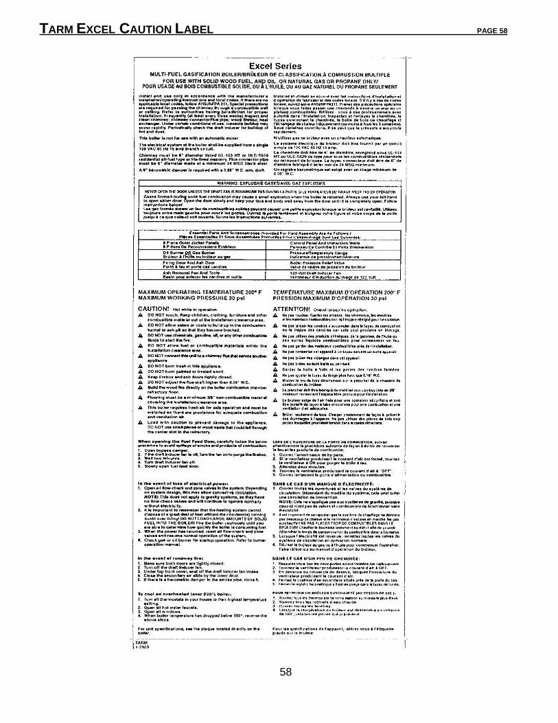
TARM EXCEL CAUTION LABEL PAGE 58
58

TARM EXCEL LISTING LABEL PAGE 59
A copy of the O-TL listing label for the H. S. Tarm Multi-fuel Gasification Boiler, Series 2000,
also known as the Tarm EXCEL series, is shown below:
59

BOILER Parts List PAGE 60
60
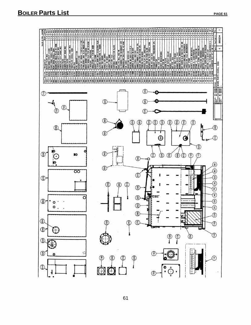
BOILER Parts List PAGE 61
61