addendum 2.9a sampling and analysis plan
TRANSCRIPT

License Application, Technical Report
September 2012 Addendum 2.9A-i
The Reno Creek ISR Project
ADDENDUM 2.9A
SAMPLING AND ANALYSIS PLAN

License Application, Technical Report
September 2012 Addendum 2.9A-i
The Reno Creek ISR Project
Prepared for:
AUC LLC 1536 Cole Blvd.
Suite 330
Lakewood, CO 80401
Prepared by:
TREC, Inc. Engineering and Environmental Management
900 Werner Court, Suite 150
Casper, WY 82601
SAMPLING AND ANALYSIS PLAN
Reno Creek Uranium ISR Project
Campbell County, Wyoming

License Application, Technical Report
September 2012 Addendum 2.9A-ii
The Reno Creek ISR Project
TABLE OF CONTENTS
1 INTRODUCTION AND OBJECTIVES....................................................................1
1.1 Brief Site History .................................................................................................... 1
1.2 Project Summary and Objectives ............................................................................ 1
1.3 Project Scope .......................................................................................................... 3
2 ORE BODIES: DESCRIPTIONS AND LOCATIONS ............................................3
2.1 Location .................................................................................................................. 4
2.2 Surface and Mineral Ownership and Access .......................................................... 5
3 SAMPLING AND ANALYSIS ...................................................................................5
3.1 Sampling For Radon in Air ..................................................................................... 6
3.1.1 Number and Locations of Samples ................................................................. 6
3.1.2 Sample Collection Methods and Frequency ................................................... 6
3.1.3 Analytical Parameters ..................................................................................... 7
3.2 Radionuclide Particulate in Air Sampling .............................................................. 7
3.2.1 Number and Locations of Samples ................................................................. 7
3.2.2 Sample Collection Methods and Frequency ................................................... 8
3.2.3 Analytical Parameters ..................................................................................... 8
3.3 Surface Water and Sediment ................................................................................... 8
3.3.1 Introduction ..................................................................................................... 8
3.3.2 Surface Water Hydrology ............................................................................... 9
3.3.3 Sampling Sites ................................................................................................ 9
3.3.4 Sampling Methods ........................................................................................ 10
3.3.5 Analytical Parameters ................................................................................... 10
3.3.6 Sampling Schedule........................................................................................ 11
3.4 Groundwater ......................................................................................................... 11
3.4.1 Number and Location of Samples................................................................. 12
3.4.2 Groundwater Collection Method and Frequency .......................................... 12
3.4.3 Analytical Parameters ................................................................................... 13
3.5 Soils....................................................................................................................... 13
3.5.1 Number and Location of Samples................................................................. 13
3.5.2 Sample Collection Method and Frequency ................................................... 14
3.5.3 Analytical Parameters ................................................................................... 14
3.6 Direct Gamma Radiation Field Surveys ............................................................... 15
3.6.1 Site Specific Sampling Information .............................................................. 15
3.6.2 Sample Collection Method and Frequency ................................................... 15
3.7 Vegetation and Food Crops .................................................................................. 16
3.7.1 Number and Location of Samples................................................................. 17
3.7.2 Sample Collection Methods and Frequency ................................................. 17
3.7.3 Analytical Parameters ................................................................................... 17

License Application, Technical Report
September 2012 Addendum 2.9A-iii
The Reno Creek ISR Project
4 QUALITY ASSURANCE/QUALITY CONTROL ................................................18
5 ANALYTICAL METHODS AND PROCEDURES ...............................................18
6 REFERENCES ...........................................................................................................18
List of Appendices
Appendix 1: Proposed Reno Creek Project Standard Operating Procedures
Appendix 2: Inter-Mountain Lab Quality Assurance Manual

License Application, Technical Report
September 2012 Addendum 2.9A-1
The Reno Creek ISR Project
1 INTRODUCTION AND OBJECTIVES
The purpose of this Sampling and Analysis Plan (SAP), along with the associated media-
specific Standard Operating Procedures (SOPs), is to describe the programs and
procedures for obtaining baseline radiological data in order to adequately characterize the
existing natural environment in the proposed Reno Creek Project (Proposed Project)
areas. These programs and procedures are designed to be consistent with existing
regulations and technical guidance (e.g., those of the U.S. Nuclear Regulatory
Commission and State of Wyoming Department of Environmental Quality), current
standards of practice, and defensible science. Data generated during this program will be
used to define the “baseline” against which any potential or perceived radiological
impacts of project activities can be measured and compared. This SAP describes general
field sampling and measurement methods, sampling locations and frequencies, and
analytical requirements. The SAP establishes the criteria by which sample locations are
selected. Detailed sample collection and field measurement protocols are contained in a
set of SOPs identified in and provided as Appendix 1 to this SAP. In addition to media-
and program element-specific SOPs (soil, water, etc.), procedures of potential relevance
to all field sampling and measurement programs, such as sample and data management
and equipment decontamination are also described in the SOPs. A supplementing
Appendix 2, Inter-Mountain Lab (IML) Quality Assurance Manual, describes IML’s
quality assurance routines.
1.5 Brief Site History
Substantial historical exploration, development, and permitting has been performed on
the Reno Creek Property. Beginning in the late 1960s and continuing into the mid 1980s,
roughly 1,000 exploration borings were drilled on the Reno Creek Property. (Figures
2.6B-1 through 2.B-3 in TR Addendum 2.6-B). Significant mine permitting studies,
including construction, successful operation and subsequent reclamation of an in-situ
recovery pilot plant were also performed over the years.
1.6 Project Summary and Objectives
The In-Situ Recovery (ISR) process envisioned by AUC is a “phased,” iterative process
and, as a result, AUC, LLC will develop the Proposed Action by constructing a series of
sequentially developed Production Units to recover uranium from identified ore bodies at
the Proposed Project site. The development of these Production Units and the
accumulation of a complete sampling database will not take place until AUC is issued an
NRC Source Materials License and installs injection, recovery, and monitor well systems.
AUC’s engineers and geologists will continuously assess data as it is obtained and apply

License Application, Technical Report
September 2012 Addendum 2.9A-2
The Reno Creek ISR Project
new information to the next phase or activity, thus ensuring that subsequent exploration
and delineation are based on the most up-to-date information possible, to ensure proper
placement of wells. All wells, including monitor wells, will be developed to assure that
they function appropriately prior to being sampled.
Water quality sampling establishes water quality within and outside the ore zone (i.e., at
the monitor wells) and upper control limits (UCL) which will enable AUC to readily
determine if an excursion of recovery solutions has occurred because of the distinct
difference between water quality in the recovery zone and that at the monitor wells. A
“lessons learned” approach will be implemented, as the results in one Production Unit
may cause the site engineer or geologist to change design in the next. This process is both
“phased” and iterative, as each Production Unit is developed and tested with the uranium
being progressively depleted from different parts of the ore body.
The proposed Central Processing Plant (CPP) will receive and process all uranium-loaded
resins generated from ISR operations in Production Units at the Proposed Action site to
produce yellowcake (U3O8) product for shipment to a conversion facility for introduction
into the nuclear fuel cycle. All byproducts generated from the ISR process determined to
be 11e.(2) byproduct material will be disposed of in a manner consistent with the Atomic
Energy Act of 1954, as amended by the Uranium Mill Tailings Radiation Control Act of
1978 (UMTRCA) (hereinafter the “AEA”), applicable NRC regulations, and guidance. A
more detailed discussion of 11e.(2) byproduct material can be found in Section 4 of this
TR.
As each developed Production Unit depletes its portion of the identified uranium ore
bodies, AUC, LLC will develop and commence recovery in the next well field and will
begin groundwater restoration in the Production Unit in which uranium recovery has been
completed. AUC, LLC’s goal is to restore groundwater in each depleted Production Unit
to water quality levels consistent with pre-operational or baseline water quality standards
but, in any case, to satisfy the requirements of 10 CFR Part 40, Appendix A, Criterion
5(B)(5), which are preoperational baseline water quality or a maximum contaminant limit
(MCL), whichever is higher, or an alternate concentration limit (ACL). When all active
ISR operations and groundwater restoration are complete in compliance with applicable
regulations, AUC, LLC will initiate site reclamation activities, including
decommissioning and decontamination (D&D) of the CPP, Production Units, header
houses, piping, and the surrounding land areas with the ultimate goal of releasing the
Proposed Action site for unrestricted (i.e., any) potential use.
In order to obtain authorization to begin operations, AUC, LLC is seeking a combined
Source and 11e.(2) Byproduct Material license pursuant to the AEA, 10 CFR Part 40,
Appendix A Criteria, 10 CFR Part 20 radiological protection limits, 10 CFR Part 51,
National Environmental Policy Act (NEPA) regulations, and other relevant non-NRC-

License Application, Technical Report
September 2012 Addendum 2.9A-3
The Reno Creek ISR Project
related regulations, including those of the United States Environmental Protection
Agency (EPA)(e.g., 40 CFR Parts 190 and 192), and applicable NRC regulatory guides
and guidance. AUC, LLC will also be required to obtain authorization for this under other
provisions of EPA (or State’s with primacy) regulations pursuant to the Safe Drinking
Water Act’s (SDWA) underground injection control (UIC) program.
AUC, LLC’s overall goal is to construct and operate uranium ISR operations at the
proposed project in such a way as to minimize impacts to human health and the surface
and subsurface environment, provide for a reasonable return on investment, and allow for
future sustainable redevelopment of the project area. To realize this goal, the following
objectives have been established:
Obtain the necessary licenses, permits, permissions and approvals from the
appropriate Federal and State regulatory agencies and authorities within a
reasonable timeframe and budget, and
Keep other stakeholders informed during the environmental assessment and
project development activities.
The purpose of this SAP, along with the associated media-specific SOPs, is to describe
the programs and procedures for obtaining baseline radiological data in order to
adequately characterize the existing natural environment in the Proposed Project areas.
These programs and procedures are designed to be consistent with existing regulations
and technical guidance (e.g., those of the U.S. Nuclear Regulatory Commission and State
of Wyoming Department of Environmental Quality), current standards of practice, and
defensible science.
1.7 Project Scope
The Proposed Project will be developed by constructing Production Units and ISR
support facilities, as well as a CPP facility to provide chemical makeup of recovery
solutions, recovery of uranium through pressurized downflow ion exchange (IX), resin
transfer, elution and precipitation circuits, yellowcake drying, and groundwater
restoration capabilities.
2 ORE BODIES: DESCRIPTIONS AND LOCATIONS
In the Pumpkin Buttes Uranium District area, almost all important economic uranium
deposits occur in the medium- to coarse-grained sand facies of the Wasatch Formation,
and within the lower portion of the formation at the Proposed Project. The uranium
mineralization occurs as interstitial filling between and coatings on the quartz sand grains
in irregular blanket-like bodies at the geochemical boundary or reduction-oxidation

License Application, Technical Report
September 2012 Addendum 2.9A-4
The Reno Creek ISR Project
(redox) front of ancestral and current groundwater systems. The main ore bodies in the
unoxidized zone are coffinite and pitchblende (a variety of uraninite). Low concentrations
of vanadium (~100 ppm) are associated with the uranium deposits. Only trace amounts of
molybdenum and selenium are found. Scattered lenses of calcium carbonate cement
occur throughout the area, but only rarely contain anomalous uranium.
Uranium mineralization at the Proposed Project has accumulated in c-shaped forms, or
roll-fronts, at the edge of oxidized sandstone tongues. The primary solution-front deposits
occur within sandstones, interbedded with lenses of siltstone and claystone. Even though
the top and bottom limbs are mineralized, the uranium content rapidly diminishes in the
direction of the altered ground. The thickness of the ore is controlled by the thickness of
the sand bed containing the solution-front. The maximum dimensions of an ore body are
at the leading edge of the solution-front where the altered ground has ballooned out and
forms a protrusion down gradient of the original depositing groundwater flow direction
(Anderson, 1969).
The Eocene Wasatch Formation is ~500 feet thick in the Proposed Project area, and the
uranium mineralization is confined to the sandy facies and clay/sand boundaries in the
lower part of the formation. The host is a north-south trending fluvial channel which
contains discontinuous clay lenses. Uranium occurs in sinuous pods along the channel
margins or in the interior abutting the clay lenses. Ore is generally found within thick
sand units (~20-100 feet thick), extending from depths of ~170 to 450 feet, and occurring
within thick accumulations (up to 30 feet thick) in the more permeable horizons of the
sands. Thin low grade residual deposits are found in the less permeable zones where they
are protected from oxidation.
2.5 Location
The Proposed Project is located 7.5 miles southwest of Wright, Wyoming and contains
all or portions of 15 Sections (6,057 acres). Its location is described as follows:
T42N R73W – Diagonal portion of the north half of the northwest quarter of the
northwest quarter of Section 5; West half of Section 6, west half of the northeast
quarter of Section 6, and the northeast quarter of the northeast quarter of Section 6
T42N R74W – East half of Section 1, East half of the southwest quarter of
Section 1, northeast quarter of Section 12 and East half of the northwest quarter of
Section 12;
T43N R73W – South half of Section 21, southwest quarter of Section 22, West
half of Section 27, all of Section 28, south half of Section 29, northeast quarter of
section 29, south half of the northwest quarter of Section 29, southeast quarter of
Section 30, southeast quarter of the northeast quarter of Section 30, allof Section
31, ,all of Section 32, north half of Section 33, north half of the Southhalf of

License Application, Technical Report
September 2012 Addendum 2.9A-5
The Reno Creek ISR Project
Section 33, West half of the northwest quarter of Section 34 and the northwest
quarter of the southwest quarter in Section 34; and
T43N R74W – All of Section 36 and the East half of the southeast quarter Section
35.
2.6 Surface and Mineral Ownership and Access
Surface ownership within the Proposed Project area includes private and state owned
lands and no federal surface ownership. Figure 2.1-1 of the TR shows the land ownership
in the Proposed Project area. Mineral holdings in the Proposed Project area consist of
federal unpatented mining claims, private (fee) mineral leases, and state mineral leases.
Mineral ownership is shown on Figure 2.1-2 of the TR. In addition, AUC has executed
surface use agreements with all land owners who hold surface ownership in the Proposed
Project area.
3 SAMPLING AND ANALYSIS
This section describes the technical approach used in establishing baseline sampling
locations, sampling frequencies and analytical requirements for the following media:
Radon in air;
Air particulate sampling;
Surface water and sediment sampling;
Groundwater and domestic well sampling;
Surface soil and soil profile collection;
Direct gamma radiation field surveys; and
Vegetation and food crop sampling.
Each of the previously mentioned media sampling SOP’s can be found in Appendix 1.
These components of the radiological baseline study are described in the following
subsections. The guidance provided by USNRC Regulatory Guide 4.14, Radiological
Effluent and Environmental Monitoring at Uranium Mills is summarized for each
program component. However, it must be recognized that this Regulatory Guide was
written decades ago and focused on the design and layout of conventional uranium mills,
not uranium ISR facilities. Accordingly, some modifications must be made in the design
and execution of this preoperational radiological baseline program to accommodate the
uranium ISR design, site layout, and technology. These deviations are explained in the
text and justification is provided to assure that the “intent” of Regulatory Guide 4.14 has
been preserved. Many of these deviations are supported by guidance presented in
NUREG-1569, “Standard Review Plan for In Situ Leach Uranium Extraction License

License Application, Technical Report
September 2012 Addendum 2.9A-6
The Reno Creek ISR Project
Applications.” This document describes itself as providing “general guidance on
acceptable methods for compliance with existing regulatory framework.” Modifications
and deviations from Regulatory Guide 4.14 that are presented in NUREG 1569 should be
considered valid and compliant with NRC standards for the Proposed Project facility. It is
also noted that this SAP is a “living document” in that it may need to be modified/revised
per actual field conditions encountered and/or evolving regulatory requirements.
3.5 Sampling For Radon in Air
NRC Regulatory Guide 4.14 suggests radon measurements be taken at locations where
air particulates are monitored on a continuous basis or one week per month at about the
same time of the month.
3.5.1 Number and Locations of Samples
Regulatory Guide 4.14 states that measurements should be made at the center of the
milling area and at locations 750 and 1,500 meters in each cardinal direction from the
center of the site. Regulatory Guide 4.14 assumes a centralized continuous site. ISR
activities at the Proposed Project will occur at the proposed CPP and over the ore bodies
which are generally long, narrow, and discontinuous. Accordingly, radon detectors will
be placed at the air monitoring stations consistent with the layout of modern ISRs. The
locations of the radon detectors, the same location as the air monitors, are shown on
Figure 2.9-1. These locations provide a baseline characterization of the areas with the
greatest potential for impact from the ISR process. There will be six radon monitors on
the site.
3.5.2 Sample Collection Methods and Frequency
Passive monitoring of average 222
Rn air concentrations at the Proposed Project was
conducted with Radtrak® alpha-track radon detectors, also supplied by Landauer Inc.
These radon detectors, also housed at the air particulate monitoring stations, are protected
from weather and animal disturbance using field containers provided by Landauer
(Figure 2.9-19). The radon detectors are supplied by the vendor in sealed packages to
minimize radon exposure prior to the beginning of the field monitoring period. Upon
completion of the monitoring period, Landauer film-foil sealing stickers are applied to
the detector openings to prevent further radon exposure during transit back to the vendor.
The number of tracks over a pre-determined area is counted using a microscope or optical
reader. The radon concentration (in pCi/liter of air) is determined by the number of tracks
per unit area in combination with the time of exposure. These detectors are small and
require no power source. For outdoor monitoring, a re-usable protective housing is

License Application, Technical Report
September 2012 Addendum 2.9A-7
The Reno Creek ISR Project
required for each monitor. The monitors are mounted at approximately one meter off the
ground from either steel posts mounted in the ground for this purpose or on fence posts at
locations where fencing is already present. Continuous samples will be collected in
accordance with SOP 1, “Radon Concentrations in Air”. Passive alpha track detectors
will be placed as described above. A Landauer, Inc. Radtrak Long Term Radon Monitor
or equivalent will be installed at each designated sampling location. Detectors will be
exchanged and returned for analysis to the vendor on a quarterly basis.
3.5.3 Analytical Parameters
Detectors will be analyzed by the supplier. The sensitivity of the RadTrak detector is
typically in the 20 to 40 pCi/l/day range. Assuming a quarterly (90 day) exposure period,
the minimum detectable concentration will be 0.2 to 0.4 pCi/l radon in air.
3.6 Radionuclide Particulate in Air Sampling
The following sections discuss number and locations of samples to be collected and the
sampling method and frequency for sampling radionuclide particulates in the air.
3.6.1 Number and Locations of Samples
NRC Regulatory Guide 4.14 recommends a total of five air particulate monitoring
stations:
Three air monitoring stations at or near the site boundary in the downwind
direction;
One air monitoring station at the nearest residence within ten (10) km of the site
representing “highest predicted concentration”; and
One air monitoring station at a control location, upwind and remote from the site.
Continuous sampling is further suggested with quarterly composites of weekly samples
(or as necessary based on dust loading) be submitted for analysis. The chosen monitoring
stations are shown in Figure 2.9-1. Placement of particulate air samplers considered (a)
site boundary locations that during operations, will represent “points of compliance”
relative to permissible releases of radioactive materials in air to unrestricted (public)
areas; (b) selection of directions from project activities representative of
prevailing/highest frequency wind; (c) the location of nearby residence(s) that would
represent the potentially “maximally exposed offsite individual” from project airborne
releases under normal operations and/or accidental releases. Assumptions on prevailing
winds at the property were made from two main sets of data. Information from the
National Weather Service station located in Gillette, Wyoming, approximately 50 miles

License Application, Technical Report
September 2012 Addendum 2.9A-8
The Reno Creek ISR Project
from the site, records prevailing winds from the northwest and southwest. The project’s
meteorological monitoring station was placed on higher terrain near the northwest
boundary of the Proposed Project area, such that it is upwind, on unobstructed terrain.
3.6.2 Sample Collection Methods and Frequency
Air particulate samples are collected using F & J Specialty Products Models DF-40L-AC
which have been installed at permanent locations. A filter was initially collected from
each air-sampling unit on approximately a weekly basis during the three month quarters.
The collected set of filters (typically about thirteen, one per week) for each air sampling
unit is sent to a contract laboratory for analysis at the end of each calendar quarter. The
sampler units will have flow rates sufficient to ensure minimum detectable activities are
achieved. The sampler units and their operation are described in SOP 2, Air Particulate
Sampling. Continuous air sampling is via filter paper collection. Sampling is to be
conducted continuously for 12 months or more, with quarterly composites from each
station separately analyzed. Note that, as discussed in TR Section 2.9.6, a gradual
transition to monthly filter exchange was discussed with NRC staff and implemented
successfully over time. This change improved project safety and efficiency, and does not
affect data results (See SOP 2 and TR 2.9.6).
3.6.3 Analytical Parameters
Table 1 presents analytes and analytical methods for air particulate (filter) samples to
detect radionuclides in ambient air.
Table 1:Analytes and Analytical Methods for Air Particulate Filters (Analytes are
per NRC Regulatory Guide 4.14)
Radionuclide Analytical Method Reporting Level
U-Nat (total) E908.1 E-7 pCi/liter 230
Th E907.0 E-7 pCi/liter 226
Ra E903.0 E-7 pCi/liter 210
Pb E905.0 Mod 2E-6 pCi/liter
3.7 Surface Water and Sediment
3.7.1 Introduction
AUC collects surface water and sediment samples for the baseline characterization of its
Proposed Project located in Campbell County, Wyoming. The project boundary outline
and sampling locations are shown on Figure 2.9-1. The purpose of the surface water and

License Application, Technical Report
September 2012 Addendum 2.9A-9
The Reno Creek ISR Project
sediment sampling is to provide site specific information to support the submittal of a
Wyoming Department of Environmental Quality (WDEQ) Underground Injection
Control Class III application (Permit to Mine) and an application for Source Materials
License with the U.S. Nuclear Regulatory Commission (NRC). A brief description of the
surface water hydrology, sampling sites, sampling methods, quality assurance/quality
control and a general sampling schedule are presented in this sampling plan.
3.7.2 Surface Water Hydrology
The Proposed Project is located within the eastern extent of the structurally bounded
Powder River Basin (PRB) on the divide between the Belle Fourche River and Cheyenne
River Drainage Basins. The Belle Fourche and the Cheyenne Rivers are tributaries to the
Missouri River. The most significant drainage in the Proposed Project area is the Belle
Fourche River, which flows NNE through the western portion of the Proposed Project
area and drains the area by way of ephemeral tributary channels. In the Proposed Project
area, the Belle Fourche River and its tributary, the K Bar Draw, are part of the Belle
Fourche-All Night Creek sub basin. The eastern half of the Proposed Project area
contains the upper portions of two sub drainage basins: Upper Spring Creek-Antelope
Creek and Upper Porcupine Creek-Antelope Creek. The Spring Creek and Upper
Porcupine Creek are tributaries to the Cheyenne River. The Belle Fourche joins the
Cheyenne River in South Dakota.
All drainages in the Proposed Project area are ephemeral in nature. The predominant
source of surface water is from thunderstorms and spring snowmelt; flow occurs in
channels for a very short duration and is directly related to these snowmelt periods and
high intensity precipitation events. The watershed hydrology within the project area
includes man made reservoirs or stock ponds and Wyoming Pollutant Discharge
Elimination System (WYPDES) discharge sites from coalbed methane de-watering
activities. Figure 2.7A-7 in Addendum 2.7A of this TR depicts water bodies observed in
the Proposed Project area during the initial field visit (June 15th
and 16th
, 2010), and the
proposed surface water sampling locations including the observed WYPDES sites.
3.7.3 Sampling Sites
Surface water sampling sites in the Proposed Project are shown in Figure 2.9-1 of the TR.
A total of 21 sampling sites are identified including 14 WYPDES sites and 12 surface
water bodies observed in a field visit conducted June 15th
and 16th
2010.
There were no continuous surface water flows (master streams) observed during the June
field visit, therefore it is anticipated that surface flow gaging stations capable of
continuous surface flow monitoring will not be required. In some areas where surface

License Application, Technical Report
September 2012 Addendum 2.9A-10
The Reno Creek ISR Project
water bodies are lacking, an automatic sampler may be used to attain water samples from
ephemeral channels during snow melt or storm-events. The automatic sampling devices
will be positioned in the channel locations and retrieved at a convenient time after the
event.
The sampling data from the 21 sites is provided in Table 2.7A-14 in TR Addendum 2.7A.
The locations are provided in both Figure 2.7A-8 and Table 2.7A-15 of Addendum 2.7A.
Sampling began at some sites in the fall of 2010. Of the 21 sampling sites, 16 were dry at
least six months during the four quarterly sampling efforts. This is due to the seasonal
weather variations and ephemeral nature of these stock ponds, CBM outfalls and areas of
drainage where ponding can occur. To date at least four quarterly sampling efforts for
baseline studies have been conducted for all 21 sites.
In addition to the surface water sampling, 19 sediment sampling sites are proposed,
including three alternative sites. The proposed sediment sampling sites correspond with
the proposed surface water sampling sites. All sampling sites are shown on Figure 2.9-1.
3.7.4 Sampling Methods
Detailed SOP’s for surface water and sediment sampling events are shown in SOP 3 as
Appendix 1.
3.7.5 Analytical Parameters
The analytical parameter list for sediment samples is shown in Table 2 and surface water
is shown in Table 2. The analyses are conducted by a contracted laboratory. Field-
analyzed parameters are conducted with a multi-parameter water quality meter and will
include pH, temperature, electrical conductivity (EC), turbidity, ORP (Oxidation
Reduction Potential), dissolved oxygen (DO) and discharge or level where appropriate.
Table 2: Analytes and Analytical Methods for Sediment Samples (Analytes per NRC
Regulatory Guide 4.14, Table 1)
Radionuclide Analytical Method Reporting Level
U-Nat (total) E908.1 0.2 mg/kg - dry 230
Th E907.0 0.2 pCi/g 226
Ra E903.0 0.2 pCi/g 210
Pb E905.0 Mod 0.2 pCi/g
Gross Alpha E900.0 0.2 pCi/g

License Application, Technical Report
September 2012 Addendum 2.9A-11
The Reno Creek ISR Project
3.7.6 Sampling Schedule
Surface water sampling has been conducted at all proposed locations on a quarterly basis,
beginning September 2010.
Sediment sampling was scheduled to be performed at surface water sampling sites during
spring snowmelt, and during late Summer or early Fall when water body levels are
expected to be at their lowest.
3.8 Groundwater
AUC reviewed low-flow sampling techniques for acquiring baseline groundwater
samples and contacted state of Wyoming agencies to review proposed sampling methods.
As an alternative to the groundwater stabilization goals per Guideline No.8, AUC
proposes to utilize the low-flow method of sampling groundwater wells in its baseline
characterization program at the Proposed Project.
Low-flow groundwater sampling is an increasingly accepted method of collecting ground
water samples with a strict set of guidelines to ensure better sample representation and
quality. This technique eliminates the need for removal of several well volumes prior to
the collection of samples, thus reducing the amount of IDW (Investigative Derived
Waste) from wells containing contaminated water. It also improves sample quality,
accuracy, precision and variability through reduced disturbance to the well and
formation.
AUC has utilized both dedicated and non-dedicated pumps. In addition, decontamination
of the non-dedicated pump components is accomplished prior to sampling the next well.
Detailed SOPs for decontamination are shown in SOP 4.
A pneumatic bladder is used for pumping along with a controller for precise control of air
pressure and timing of the pressure and exhaust cycles. A bladder pump was selected for
the Proposed Project installation due to the depth limitations of an electric submersible
pump (200 feet max). Tubing and suspension cable will connect the bladder pump to the
surface. Nitrogen tanks connected to a 300 psi rated controller is utilized to reach the 200
to 300 psi range needed to sample the well depths proposed for the Proposed Project.
Water quality monitoring is an essential part of the low-flow sampling process.
Measurement of several chemical parameters are used to indicate when purging is
complete and sampling may begin. The measurements may be made periodically or
preferable on a continuous basis using a multi-parameter probe installed in a flow-
through cell to insure all chemical parameters have stabilized. These parameters include
pH, specific conductance, dissolved oxygen, oxidation reduction potential, temperature

License Application, Technical Report
September 2012 Addendum 2.9A-12
The Reno Creek ISR Project
and turbidity. The chemical stabilization is usually confirmed by Nephelometric
Turbidity Unit (NTU) measurements.
3.8.1 Number and Location of Samples
NRC Regulatory Guide 4.14 recommends establishing quarterly groundwater baseline
monitoring to include:
Existing wells within two kilometers (km) of tailings area that could be used for
potable water, livestock, or irrigation;
At least one well located hydrologically up gradient from tailings area as a
control/background; and
At least three wells located hydrologically down gradient from the tailings area.
Figure 2.9-1 presents the locations of regional baseline wells and plant area piezometers.
Since ISRs do not have “conventional mill tailings”, monitoring locations have been
selected based on anticipated hydrologic flow patterns relative to the production zone and
adjacent aquifers that need to be protected. Baseline monitoring also included existing
water supply wells within a two km radius of the Proposed Project boundary, as depicted
in Figure 2.9-1 of this TR. These wells include those at the closest residences to the
Proposed Project area. While there are six wells within the two km sample requirement,
these resources will likely be analyzed in the baseline study. In addition to wells within
two km outside the Proposed Project area, there are 14 baseline stock/domestic wells
sampled. Inside of the Proposed Project area, seven monitoring well clusters with a total
of 39 wells have been installed for characterizing the up-gradient and down-gradient flow
from the locations of the proposed CPP and backup pond. These regional baseline well
clusters will provide samples over a range of depths in the subsurface.
3.8.2 Groundwater Collection Method and Frequency
Samples were collected quarterly from new and existing monitoring wells as well as
agricultural or domestic use wells located within two km of the site when seasonally
available for sample retrieval. Many wells located on maps of the Proposed Project area
are no longer functional or are not available during all seasons of the year. Wells that are
not capable of being sampled will be recorded during seasonal sampling. Minimum
sample volumes, preservation requirements, and holding times are presented in SOP 5,
Groundwater Sampling.

License Application, Technical Report
September 2012 Addendum 2.9A-13
The Reno Creek ISR Project
3.8.3 Analytical Parameters
The radiological analytes and recommended analytical methods to be used for
groundwater and domestic well samples are listed in Table 3 below.
Table 3: Analytes and Analytical Methods for Groundwater and Surface Water
Samples (Analytes are per NUREG 1569, Table 2.7.3-1).
Radionuclide Analytical Method Reporting Level
U-Nat (dissolved) EPA 200.8 0.0003 mg/L
226Ra SM 7500-Ra B 0.2 pCi/L
Gross Alpha SM 7110B 2 pCi/L
Gross Beta SM 7110B 4 pCi/L
3.9 Soils
NRC Regulatory Guide 4.14 suggests, for mills and tailings disposal sites, that surface
soil samples be collected to a depth of five (5) centimeters. NRC further recommends that
samples be obtained once prior to construction. While Regulatory Guide 4.14 specifies
surface soil samples to a depth of five cm, the current reclamation standards (e.g., 10
CFR 40, Appendix A, Criterion 6) specify surface soil samples to a depth of fifteen (15)
cm. Therefore, the baseline surface soil samples will be taken to a depth of 15 cm. This
deviation from the Regulatory Guide is necessary to establish a preoperational baseline
for comparison in the future with current reclamation standards consistent with the
potential radiological impact of modern ISRs. Additional revisions from the approach
described above is presented and justified below. NRC Regulatory Guide 4.14 suggests
subsurface soil samples be obtained at the center of operations and at 750 meters in four
cardinal directions in order to define the radiological profile of subsurface soils in the
Proposed Project areas. Three samples at each location should be obtained one time prior
to construction to depth of one meter at 0 to 30, 30 to 60 and 60 to 100 cm depth
intervals. In addition, NUREG 1569 suggests that a general description of the site soils
and their properties be provided to support an evaluation of the environmental effects of
construction and operation on erosion. All soil sampling will be carried out in accordance
with SOP 6, Surface Soil and Soil Profile Sampling.
3.9.1 Number and Location of Samples
NRC Regulatory Guide 4.14 recommends locations for surface soil samples to be
collected at 300 meter (m) intervals out to 1,500 m, in the eight cardinal directions from a
point representing the geometric center of onsite processing activities and also at the air
monitoring stations. This sampling pattern is not likely to sample some areas potentially
impacted by the recovery process. NRC Regulatory Guide 4.14 also recommends a total

License Application, Technical Report
September 2012 Addendum 2.9A-14
The Reno Creek ISR Project
of five soil profiles, collected one time at the center of the tailings pile and one in each
cardinal direction. AUC has modified the Guide’s sampling plan to reflect its intent in the
context of a proposed ISR facility. Figure 2.9-1 displays the locations of the soil samples
actually collected. It should be noted that ISR uranium processing takes place below
grade and therefore no radionuclide particulates are expected to be generated during the
recovery process. Modern vacuum dryers as planned for this project produce virtually no
particulate emissions under normal operations. Uranium packaging operations will also
be strictly controlled to prevent particulate releases. Thus, the only significant potential
radiological releases from these production activities would be liquids from leaks and
spills, and radon gas (see USNRC NUREG 1910, GEIS, Sections 2.4.2.3 and 4.2.11.2,
for further discussions of potential ISR releases). AUC has adjusted the soil sampling
location requirements to reflect the differences between conventional mining/milling
operations and ISRs. For the Proposed Project, soil sample locations have been selected
to emphasize areas on site most likely to be impacted by the ISR process. Locations
potentially impacted by the ISR are the likely locations of the CPP, the backup pond, and
recovery well locations along the major ore bodies where lixiviant could leak from well
heads and header houses. Soil profiles that include surface soil samples are collected at
such areas of interest. All sample locations are recorded using GPS coordinates.
3.9.2 Sample Collection Method and Frequency
Surface soil samples are collected in accordance with SOP 6, Surface Soils and Soil
Profile Collection. Samples are obtained at each location from the top 15 cm of surface
soil or at the bedrock surface, wherever is shallower. In addition, soil profile samples are
collected at 0-30 cm, 30-60 cm, and 60-100 cm.
3.9.3 Analytical Parameters
Table 4 summarizes the analytes and analytical methods for surface soil and soil profile
samples. All surface soil samples will be analyzed for uranium, 226
Ra, and gross alpha. In
addition, soil samples from the six air monitoring stations as well as 10 percent of the
remaining surface soil samples will be analyzed for 230
Th and 210
Pb. Regulatory Guide
4.14 requires of one of the five required soil profiles be analyzed for 230
Th and 210
Pb.. To
match the intent of this requirement, 10 percent of the soil profiles will be analyzed for
these additional radionuclides.

License Application, Technical Report
September 2012 Addendum 2.9A-15
The Reno Creek ISR Project
Table 4. Analytes and Analytical Methods for Surface and Subsurface Soil Samples
(Analytes are per NRC Regulatory Guide 4.14, Table 1)
Radionuclide Analytical Method Reporting Level
Uranium (Total) 200.8 0.2 pCi/g - dry 230
Th ACW10 0.2 pCi/g 226
Ra E901.1 0.2 pCi/g 210
Pb OTW01 1 pCi/g
3.10 Direct Gamma Radiation Field Surveys
Regulatory Guide 4.14 (RG 4.14) calls for a pre-operational gamma survey, but was
written prior to the availability of portable computers and GPS satellites. The Guide was
written to support the licensing of conventional (hard-rock) uranium mills, and calls for
the recording of some 80 individual gamma exposure rate measurements at on a radial
grid centered on a proposed uranium mill location (NRC, 1980). Portions of the guidance
don’t apply well to ISR facilities, which have no mill, tailings, nor ore pile facilities. In
keeping with ISR license application and review guidance described in Regulatory Guide
3.46 (NRC, 1982) and NUREG-1569 (NRC, 2003), and with radiological survey
guidance specified in the Multi-Agency Radiation Survey and Site Investigation Manual
(NRC, 2000), Tetra Tech used GPS-based scanning systems to record baseline gamma
exposure rates over the entire site. The resulting set of measurements includes the data
specified in RG 4.14.
3.10.1 Site Specific Sampling Information
For the Proposed Project, gamma surveys at the site(s) will utilize multiple GPS-based
gamma scanning systems mounted on specially designed support systems attached to all
terrain vehicles (ATVs) or backpacks depending on the nature of terrain to be covered or
other site circumstances. Sampling was be performed in accordance with SOP 7.
3.10.2 Sample Collection Method and Frequency
The radiation survey systems employed vehicle (Yamaha Rhino® ATV and Jeep
Rubicon®) and backpack-mounted equipment. The vehicles were configured to minimize
terrain damage, and feature roll cages and safety harnesses to reduce worker risk. Figure
2.9-3 presents a photo of the scanning systems.
Both the Jeep and Rhino vehicles employ adjustable systems to carry two Ludlum 44-10
two-inch sodium iodide (NaI) gamma radiation detectors and paired GPS receivers. The

License Application, Technical Report
September 2012 Addendum 2.9A-16
The Reno Creek ISR Project
detectors are coupled to Ludlum 2350-1 rate meters. The permanently paired instruments
are calibrated annually by the manufacturer using Cs-137 sources, and report gamma
exposure rate in μR/h. Simultaneous GPS and gamma radiation exposure rate data are
recorded once per second by each detector system. Data are recorded on netbook
computers using proprietary software (ComReader©, Tetra Tech, 2007). System
configuration includes eight foot spacing between the vehicle-mounted detectors, with
each detector positioned approximately 3.5 feet above the ground to avoid obstructions.
Separate GPS receivers and mapping programs are used to display track data in real-time.
Backpack systems use single radiation detectors but are otherwise identical to the
vehicle-mounted systems.
Based on previous experience, lateral NaI detector response to significantly above-
background gamma source areas extends out to roughly five feet, giving each detector an
estimated “field of view” 10 feet in diameter. This does not imply that a detector can
discriminate gamma radiation from a small point source five feet away, but does suggest
that photons from larger source areas are likely to be detected at that distance. The
sensitive track width for each vehicle’s two-detector system is therefore estimated to be
about 18 feet. Vehicle scanning speeds at the Proposed Project generally ranged between
two and 10 mph depending on terrain difficulty, with an average speed of approximately
five mph.
Target coverage for the Proposed Project, as for other pre-license facilities where Tetra
Tech has performed similar work, was 100 meter spacing between the scan vehicles (10
meter scan tracks). The tracks were pre-set as computer shape files used to direct the
vehicles during scanning. Practical considerations such as steep terrain and obstructions
influenced actual courses traversed by the vehicles. Where ore deposits were known to
exist, 50 meter track spacing was targeted, given the increased likelihood of surface
expressions of uranium ore. Where specific study areas were selected to develop
correlations with soil samples, scan density was increased to 100 percent (vehicle track
spacing less than 18 feet).
3.11 Vegetation and Food Crops
NRC Regulatory Guide 4.14 suggests the sampling of all food products grown on and
within three km of the site at the time of harvest, plus vegetation from grazing areas near
the site with the highest predicted air particulate concentration during operation. Sample
collection will be carried out in accordance with SOP 8, Vegetation Sampling.

License Application, Technical Report
September 2012 Addendum 2.9A-17
The Reno Creek ISR Project
3.11.1 Number and Location of Samples
A field reconnaissance is used to assess species presence and abundance and to select
general areas for plant sampling for each area. A list of species is recorded that are at
least locally common in the areas of interest. Potential sampling areas for various species
are marked on a map or aerial photograph. Vegetation samples are taken that best
represent the diets of animals grazing on or near the Proposed Project area. Sampling is
focused on areas that are most likely to be impacted by the production and recovery
process. Samples are taken from the grass and shrub species that represent the majority of
the grazing diet.
3.11.2 Sample Collection Methods and Frequency
Samples are taken three times during the growing season for grazed vegetation, in
accordance with Regulatory Guide 4.14.
Three samples will be collected during the growth/harvest season. Sample sites locations
are documented with a GPS field unit, and the coordinates downloaded into a GIS map of
the Proposed Project.
3.11.3 Analytical Parameters
Table 5 presents analytes and analytical methods for analyzing vegetation and food
products. All surface vegetation and food product samples will be analyzed for uranium,
thorium-230, radium-226, lead-210 and polonium-210.
Table 5. Analytes and Analytical Methods for Vegetation and Food Product
Samples (Analytes are per NRC Regulatory Guide 4.14, Table 1)
Radionuclide Analytical Method Reporting Level
U-Nat (total) EPA 200.8 2.0E-7 µCi/kg 230
Th ACW10 2.0E-7 µCi/kg 226
Ra SM 7500 Ra-B 5.0E-8 µCi/kg 210
Pb OTW01 4.0E-6 µCi/kg 210
Po OTW01 1.0E-6 µCi/kg

License Application, Technical Report
September 2012 Addendum 2.9A-18
The Reno Creek ISR Project
4 QUALITY ASSURANCE/QUALITY CONTROL
Quality controls for each type of sampling will be performed in accordance with the
technical specifications provided by the selected vendor laboratory or service provider.
Samples will be collected, packaged, stored and transferred/delivered in accordance with
the service provider’s quality assurance program, using laboratory-specified chain of
custody procedures and forms.
5 ANALYTICAL METHODS AND PROCEDURES
Analytical services are contracted to Intermountain Laboratories of Sheridan, Wyoming.
Analyses conducted by the laboratory will be completed in accordance with the
laboratory’s Quality Assurance Manual (QAM), as reviewed/approved by AUC project
staff. The laboratory QAM is appended to this SAP as Appendix 2. Certified,
commercially clean sample containers will be obtained from the contract laboratory or in
accordance with the laboratory’s QA program. Required preservatives will be added to
the containers, as appropriate, by the contract laboratory. As necessary (typically only for
animal tissue), samples will be stored on ice in an insulated cooler immediately following
sample collection to maintain proper temperatures. In general, samples collected for
radiological analyses do not require storage on ice since the temperature does not impact
the radionuclide concentrations. Soil and sediment samples do not require preservation.
Holding times are as specified by the contract laboratory. Samples will be prepared for
analyses in accordance with SOP 9, Sample Management which references methods
contained in, e.g., EPA methodology as defined in Methods for Chemical Analysis of
Water and Wastes, EPA-600/4-79-020 or Standard Methods for the Examination of
Water and Wastewater, 20th Edition, EPA SW-846, and 40 Code of Federal Regulations
(CFR) 136. Sample preparation requests will be noted on the chain of custody form. The
contract laboratory will be responsible for reviewing and validating data generated at the
laboratory.
6 REFERENCES
Church, Peter E., and Granato, Gregory E., "Bias in Ground Water Data Caused By Well-
Bore Flow in Long-Screen Wells" Ground Water, Vol.34, No.2 1996.
Gibs, J., Brown, Allan G., Turner, Kenneth S., MacLeod, Cecilia L., Jelinski, James C.,
Koehnlein, Susan A., "Effects of Small-Scale Vertical Variations in Well-Screen
Inflow Rates and Concentrations of Organic Compounds on the Collection of
Representative Ground-Water-Quality Samples" Ground Water, Vol. 31, No.2
March-April, 1993.

License Application, Technical Report
September 2012 Addendum 2.9A-19
The Reno Creek ISR Project
Hart, Barbara F., Tomlinson, Rodger B., and Chaseling, J., "Using the Stabilization
Plateau to Estimate Optimum Well Purge Volume", Ground Water Monitoring
Review, Summer, 2000.
Hutchins, Stephen R., Acree, Steven D., "Ground Water Sampling Bias Observed In
Shallow, Conventional Wells" Ground Water Monitoring Review, Winter, 2000.
Imbrigiotta, Thomas E., Gibs, J., Fusillo, T.V., Kish, George R., Hochreiter, Joseph J.,
"Field Evaluation of Seven Sampling Devices for Purgeable Organic Compounds
in Ground Water" Ground-Water Contamination: Field Methods, ASTM STP
963, A.G. Collins and A. J. Johnson, Eds., American Society for Testing and
Materials, Philadelphia, PA 1998.
McAllister, P.M., Chiang, C.Y. "A Practical Approach to Evaluating Natural Attenuation
of Contaminants in Ground Water", Ground Water Monitoring Review, Spring,
1994.
New Jersey Department of Environmental Protection (NJDEP) N.J.S.A.13:1D et seq., " ",
N.J.A.C. 7:26E et seq., July 1999.
Parker, Louise V. "The Effects of Ground Water Sampling Devices on Water Quality: A
Literature Review" Ground Water Monitoring Review, Spring,1994.
Puls, Robert W., and Barcelona, Michael J., "Low-Flow (Minimal Drawdown) Ground-
Water Sampling Procedures", USEPA Report EPA/540/S-95/504, April, 1996.
Puls, Robert W., and Barcelona, Michael J., "Ground Water Sampling for Metals
Analyses", USEPA Report EPA/540/4-89/001, March 1989
QED Environmental Systems - Spectra Sample™ from QED - A Flow Equalization Inlet
for Long-Screened Wells
Rose, S., and Long, A., "Monitoring Dissolved Oxygen in Ground Water: Some Basic
Considerations" Ground Water Monitoring Review , Winter, 1998.
USEPA, Low-Flow (Minimal Drawdown) Ground Water Sampling Procedures, USEPA
Report EPA/540/S-95/504. December, 1995.
USEPA, Method 1669: Sampling Ambient Water for Trace Metals at EPA Water Quality
Criteria Levels, Office of Water Engineering and Analysis Division, April, 1995.

License Application, Technical Report
September 2012 Addendum 2.9A-20
The Reno Creek ISR Project
USGS, Ground-Water Data – Collection Protocols and Procedures for the National
Water-Quality Assessment Program: Selection, Installation, and Documentation
Of Wells, and Collection of Related Data, U.S. Geological Survey, Report 95-
398. 1995.
USGS, Ground-Water Data-Collection Protocols and Procedures for the National
Water-Quality Assessment Program: Collection and Documentation of Water
Quality Samples and Related Data, U.S. Geological Survey Report 95-399. 1995.
USGS, Handbooks for Water-Resources Investigations, Techniques of Water-Resources
Investigations, Book 9, Chapter A2, August ,1998.
USGS, National Field Manual for the Collection of Water-Quality Data, Selection of
Equipment of Water Sampling, USGS, August 1998.
Wyoming Department of Environmental Quality, Memorandum for Record, RE: Use of
DEQ Water Quality/Groundwater Pollution Control (WQ/GPC) Policy Document
on Groundwater Sampling for Metals for Long-Term Corrective Action-Type
Monitoring, attached WQ/GPC Policy Document, Groundwater Sampling for
Metals: Option 2: Low Stress (Low Flow) Technique, Summary, April 6, 2005,
was developed by Wyoming DEQ WQ/GPC February 23, 2009
Wyoming Department of Environmental Quality, Water Quality Division, Compliance
Monitoring and Siting Requirements for Unlined Impoundments Receiving
Coalbed Methane Produced Water, Attachment 11- Sampling for Metals,
November 2008 (Revised)
Wyoming Department of Environmental Quality, Voluntary Remediation Program
(VRP), FACT SHEET #29 - Sampling and Analysis Plans, 04/18/07 – R1 Page 1
of 19. http://deq.state.wy.us/volremedi/inedex.asp
Yeskis, Douglas, and Zavala, B., "Ground Water Sampling Guidelines For Superfund and
RCRA Project Managers" Office of Solid Waste and Emergency U.S.E.P.A.
Report 542-S-02-001, May, 2002, www.epa.gov/tio, www.clu-in.org/tio/tsp

The Reno Creek ISR Project License Application, Technical Report
September 2012 2.9A Appendix 1-i
The Reno Creek ISR Project
APPENDIX 1
STANDARD OPERATING PROCEDURES (SOP)

1 of 5
Prepared For:
AUC LLC
TREC, Inc. Engineering & Environmental Management
1800 W. Koch, Suite 6
Bozeman, MT 59715
900 Werner Court, Suite 150
Casper, WY 82601
STANDARD OPERATING PROCEDURE NO.01 MONITORING FOR RADON IN AIR
Reno Creek Uranium ISR Project Campbell County, Wyoming
2.9A Appendix 1-1Technical Report

2 of 5
Revision History
Rev. Date Originator Description of Change
1 07/12/10 Ray De Luna New Release
2 01/22/12 Robert Meyer Revision
Note: All released revision level changes to specifications referenced in this document require the originator of that specification to update the revision level and release date documented here in specification number.
2.9A Appendix 1-2Technical Report

SOP No.01 Monitoring for Radon In Air
3 of 5
STANDARD OPERATING PROCEDURE NO. 01
MONITORING FOR RADON IN AIR
SCOPE The purpose of this Standard Operating Procedure (SOP) is to provide guidance on the procedures to be employed when deploying and collecting radon monitors used in the monitoring of ambient Rn-222 (radon). The purpose of the monitoring is to establish the baseline natural concentrations of radon in the air at selected locations within the project area prior to operations, and later to assess potential operational impacts from the release of radon.
HSSE
POTENTIAL HAZARDS
Walking/working surfaces
Slopes and terrain
Pinch points
Sharp edges
Weather
Body position
Heat/cold stress
Fitness to work
Exposure to poisonous plants/animals/bugs
Wind
Lifting
Hand tools
CONTROLS Proper PPE
Awareness of surroundings and weather conditions
Use caution when walking on uneven surfaces
Tool inspection
Housekeeping
Follow weather safety policies
Use backpack to help carry equipment; keep equipment orderly
Stay hydrated, take warm-up/ cool-down breaks as appropriate. Dress in layers
STOP WORK TRIGGERS
Inability to safely access work area
Improper PPE
Improper tools
Defective equipment
Inclement weather
Severe biological hazards within work zone
PPE REQUIRED Steel toe boots
Safety glasses
High visibility vest
Nitrile or latex gloves
Long sleeve shirt
Long trousers
Eye wash
Field first aid kit
REQUIRED TOOLS SOP and Health and safety plan
Weather resistant field log book and field data forms
2.9A Appendix 1-3Technical Report

SOP No.01 Monitoring for Radon In Air
4 of 5
Chain of Custody forms
Tool set
Digital camera
GPS receiver
Water proof ink pen
Radon monitors in sealed film-foil bags and detector log sheets (provided by the monitor supplier)
First trip: Protective housing for each monitor being deployed
Metallic labels to seal each monitor upon retrieval (provided by radon monitor supplier)
Plastic zip-lock bags
First trip: Devices for fastening the protective housing at each monitoring location
Field log book
First trip: flexible screen or nylon mesh material to cover bottom of housing as needed to retain and prevent loss of detector should the Velcro fastener fail
Duct tape and/or packaging tape to secure retaining screen at bottom of housing
PROCEDURES
PRIOR TO SAMPLING
Prior to emplacing or replacing the radon monitors, follow the procedures described below:
Keep the radon monitors in the sealed film-foil bags until ready to install into the protective housings at each location. Prior to visiting the site, carefully inspect the integrity of the film-foil packaging seals. If a seal is compromised, use a monitor from a properly sealed package if possible, or contact the vendor for an immediate replacement. If the package is believed to be compromised, detail in the field log book the batch number on the package, the individual detector ID numbers involved, and the steps taken to resolve the problem.
Store the metallic labels in a safe place – these will be needed during monitor retrieval.
RADON MONITOR PLACEMENT
During the first trip, the placement of the radon monitor at each location should be completed as described below:
1. At the monitoring location, permanently attach the protective housing to the inside of the metal fence (protected from cattle/pronghorn) surrounding the air particulate monitor, at roughly five foot height.
2. Open the sealed film-foil bag, remove and mark on the detector label the station ID number and date deployed.
3. Ensure the radon monitor is securely fastened (Velcro) to the inside bottom of the clear plastic cup.
4. Remove the clear acrylic retaining ring from the protective housing by removing the wing nuts. After installing the ambient gamma monitor per SOP #02, install the assembled radon cup inside the protective housing and replace the retaining ring. (Note: Opening of the cup should be facing downward)
5. Cover the retaining ring opening with wire mesh and secure with the wing nuts to prevent loss of the detector should the Velcro fastener fail during the sampling period.
6. Fill in the field log book and detector log sheet with the serial number on the monitor label, date and time installed and the location information in the location/comments area.
2.9A Appendix 1-4Technical Report

SOP No.01 Monitoring for Radon In Air
5 of 5
RADON MONITOR RETRIEVAL
Prior to quarterly retrieval of the radon monitors, verify that the metallic labels are packed with the items going to the field for retrieval activities. The retrieval of the radon monitors at each location should be completed as described below:
1. Remove the cup from the protective housing by removing the flexible retaining screen and the clear acrylic retaining ring.
2. Remove the radon monitor from the plastic cup.
3. Attach the metallic label to the monitor by covering the filtered openings. (Note: Verify that the metallic label is placed over the filtered openings as soon as it is removed from the plastic cup to stop exposure to radon).
4. On the provided space on the detector label, mark the date the removed.
5. Place monitor in a Zip-loc bag and seal.
6. Label Zip-loc bag with serial number from the monitor label, monitoring location id, date and time installed and retrieved
Deploy the monitors for the next quarter using steps 2 through 6, Radon Monitor Placement, above.
RETURN TO MONITOR SUPPLIER
Return all radon monitors and the detector log sheet to the monitor supplier for analysis via traceable shipping. Copies of all forms should be retained with the field notes.
DOCUMENTATION All information pertinent to field monitoring must be recorded in a log book. The field log book should be a weather-resistant, bound book designed specifically for field use. A log entry shall contain, at a minimum, the following information:
The monitor identification number
GPS coordinates of sampling location
Name of monitoring technician(s)
Weather conditions upon arrival and departure
Date and time of arrival
Start and end dates/times of sampling event
General notes on the condition of the monitors, housings, stations, integrity of film-foil packaging, etc.
Problems, downtime or delays
Decontamination times and methods if needed
Deviations from SOPs/Work Plan/Sampling Plan
Other field observations
At the conclusion of a task or when a logbook has been completed, it will be submitted to
the Field QA/QC Coordinator for records retention by the document control coordinator.
REPORTING Enter data into the correlating spreadsheet, QA/QC data, and transmit for database entry.
2.9A Appendix 1-5Technical Report

1 of 5
Prepared For:
AUC LLC
TREC, Inc.
Engineering & Environmental Management
1800 W. Koch, Suite 6
Bozeman, MT 59715
900 Werner Court, Suite 150
Casper, WY 82601
STANDARD OPERATING PROCEDURE NO.02 AIR PARTICULATE SAMPLING
Reno Creek Uranium ISR Project Campbell County, Wyoming
2.9A Appendix 1-6Technical Report

1 of 5
Revision History
Rev. Date Originator Description of Change
1 07/10/10 Traci Nickerson New Release
2 11/15/10 Traci Nickerson Updated procedures
3 05/19/11 Ray DeLuna Updated procedures
Note: All released revision level changes to specifications referenced in this document require the originator of that specification to update the revision level and release date documented here in specification number.
2.9A Appendix 1-7Technical Report

SOP No. 02 Air Particulate Sampling
3 of 5
STANDARD OPERATING PROCEDURE NO. 02
AIR PARTICULATE SAMPLING
Authorized for use:
Revision 3- 5/19/11
SCOPE The purpose of this Standard Operating Procedure (SOP) is to provide the procedures for the collection of air monitoring sample filters for establishing baseline concentrations of radionuclides in air. Air particulate samples are collected using F&J Specialty Products Models DF-40L-AC Digital Flow Meter (DFM). A filter is collected from each air-sampling unit at pre-determined intervals. The collected set of filters for each air sampling unit is sent for contract laboratory analysis at the end of each quarter.
HSSE
HAZARDOUS ENERGY
Electric
CONTROLS Properly grounded and sealed electrical junctions
OTHER POTENTIAL HAZARDS
Walking/working surfaces
Slopes and terrain
Pinch points
Sharp edges
Weather
Body position
Heat/cold stress
Fitness to work
Exposure to poisonous plants/animals/bugs
Wind
Lifting
Hand tools
CONTROLS Proper PPE
Awareness of surroundings and weather conditions
Use caution when walking on uneven surfaces
Follow weather safety policies
Use backpack to help carry equipment; keep equipment orderly
Tool inspection
Housekeeping
Stay hydrated, take warm-up/ cool-down breaks as appropriate. Dress in layers
Show up on the job fit to work, if not fit to work individual cannot work
STOP WORK TRIGGERS
Inability to access the work area safely
Inclement weather
Improper PPE
Defective equipment
PPE REQUIRED Safety glasses
High visibility vest
Nitrile gloves-exchange for new gloves at each site
Long sleeve shirt
Long trousers
REQUIRED TOOLS Blank secured digital cards (SD card)
4” glass fiber filters
Tool kit complete with zip-ties, socket set, electrical tape, bolts, hose clamps,
2.9A Appendix 1-8Technical Report

SOP No. 02 Air Particulate Sampling
4 of 5
screwdriver, tweezers, nitrile gloves, re-sealable plastic bags, indelible marker, etc.
Field log book, field forms and instrument manuals
Petri dishes
Key for equipment case padlock
PROCEDURES
FILTER SAMPLE COLLECTION
To initiate a sampling event:
1. Unlock sampler and open lid.
2. Record charge voltage, solar amps and load amps from solar controller.
3. Record sampling rate from sampler (Flow Rate).
4. On sampler, with units on ‘Flow’, press ‘reset’ to pause sampling event.
5. On data storage device press ‘finish’. The ‘Write’ LED will blink a few times.
6. When the ‘Finish’ LED blinks, remove the SD card and bring back to office. Insert blank SD card into data storage device, click into place.
7. Press ‘Reset’ button on data storage device, LED will flash once.
8. On sampler, scroll with ‘Units’ button and record ‘Total Time’ and ‘Total Volume’.
9. Remove filter assembly from protective shroud by releasing the quick disconnect.
10. Hold filter assembly upright and carefully unscrew top. Take care in a windy environment not to allow the filter to blow loose or particulate to fall off the filter.
11. Remove filter with tweezers, fold dust side in, and place in a clean, protective Petri dish.
12. Place the closed Petri dish into a clean re-sealable plastic bag and seal the bag.
13. Use permanent marker to record filter ID and ‘Total Volume’ of sample (from sampler), sampler’s initials and time of sample collection on the outside of the bag.
Note: Filter ID format: sample station number, sample number, year, month, day (e.g., AM3-003-110325), refer to SOP No.12 Sample Management.
No preservation measures are required during collection and storage of the air filters. The Zip-loc bag containing the samples should be stored in the sampler case until samples are sent to the contracted laboratory.
14. Clean the air sample filter holder using a soft cloth. Using tweezers carefully place a new filter in the cavity of the filter assembly rough side up, making sure not to touch either side of the sampling area. Hand tighten the filter holder ring, keeping the filter centered properly.
15. Reconnect the air sampler filter holder to the quick disconnect under the protective shroud, making sure that it ‘clicks’ into place.
16. Press the ‘Units’ button on the Digital Flow Meter (DFM) to advance the green LED to display ‘Flow’, ‘elapsed time’ and total ‘Volume’.
17. Reset ‘Total Time’ and ‘Total Volume’ by pressing the ‘reset’ button while these are indicated with a green LED light on the display. The values will read zero when reset.
18. On sampler, with DFM on ‘Flow’, press ‘Reset’ to initiate new event. Pump will slowly charge up to approximately 33.0 liters per minute (lpm). If pump does not reach roughly 30-32.0 lpm, refer to the Trouble Shooting section of this SOP.
19. Record date and time the new event was initiated.
In office:
1. Insert card into SD card reader.
2. Save .csv file to the Data Loggers Sampling Data folder using air monitoring station name and date in the header of the .csv file.
2.9A Appendix 1-9Technical Report

SOP No. 02 Air Particulate Sampling
5 of 5
3. Open field_data.xls and record field data in the appropriate fields.
TROUBLE SHOOTING
If the average sampling rate is below about 27 lpm (actual flow) over a one week period, the filter should be changed and/or equipment checked. This can be caused by dust loading of the filter, incorrect flow setting on the pump, or low power.
If the battery voltage drops below about 12.5V-the battery should be charged on-site and sampling should continue, but the system should be checked promptly for proper operation and charging. Check the solar panel for any sign of obstruction (e.g., snow, mud, broken panel).
If the load amps are not 0.4-0.8 amps while pump and data recorder are running, check the tubing connection from the pump to the filter housing, and the filter housing, for leaks or obstructions.
If data are missing from electronic diagnostic data, insert a blank SD card and confirm that the new SD card is collecting data.
DOCUMENTATION
All information pertinent to field monitoring must be recorded in a log book, regardless of the type of monitoring. The field log book should be a weather-resistant, bound book designed specifically for field use. A log entry shall contain, at a minimum, the following information:
The monitor identification number
GPS coordinates of sampling location
Name of monitoring technician(s)
Weather conditions upon arrival and departure
Date and time of arrival
Start and end times of sampling event
General notes on the condition of the monitors, housings, stations, integrity of film-foil packaging, etc.
Problems, downtime or delays
Decontamination times and methods
Deviations from SOPs/Work Plan/Sampling Plan
Other field observations, including problems observed and problem solutions developed.
REPORTING Enter data into the correlating spreadsheet, QA/QC data and transmit for database entry.
2.9A Appendix 1-10Technical Report

1 of 8
Prepared For:
AUC LLC
TREC, Inc. Engineering & Environmental Management
1800 W. Koch, Suite 6
Bozeman, MT 59715
900 Werner Court, Suite 150
Casper, WY 82601
STANDARD OPERATING PROCEDURE NO.03 SURFACE WATER SAMPLING
Reno Creek Uranium ISR Project Campbell County, Wyoming
2.9A Appendix 1-11Technical Report

2 of 8
Revision History
Rev. Date Originator Description of Change
1 07/12/10 Ray DeLuna New Release
2 05/05/11 Traci Nickerson Updated Procedures
3 01/22/12 Robert Meyer Minor edits
Note: All released revision level changes to specifications referenced in this document require the originator of that specification to update the revision level and release date documented here in specification number.
2.9A Appendix 1-12Technical Report

SOP No.03 Surface Water Sampling
3 of 8
STANDARD OPERATING PROCEDURE NO. 03
SURFACE WATER SAMPLING
Authorized for use:
Revision 3
SCOPE This purpose of this Standard Operating Procedure (SOP) is to provide guidance regarding the collection of surface water samples for establishing baseline concentrations of key radionuclides and chemical properties. The baseline will help determine potential impacts from mining activities during operation or closure, as well as defining baseline water resource for purposes of salvage and replacement within the mining operation and ultimate reclamation. The monitoring program will continue during operations in accordance with regulatory requirements. The water samples will be submitted to a contract laboratory for analysis for naturally occurring radionuclides in the uranium decay series and specific chemical constituents as required.
HSSE
CHEMICAL HAZARDS HNO3 - sample preservation
H2SO4 - sample preservation
pH buffers (4.00 s.u., 7.00 s.u., 10.00 s.u.) - standards
Conductivity standard
ORP standard
Liquinox decontamination detergent
CONTROLS PPE – nitrile or latex gloves, safety glasses
Proper hygiene
If using pre-preserved bottles, store empty bottles on ice if ambient temperature is greater than 55ºF
Store bottles separately from other equipment
Open pre-preserved bottles so that bottle is facing away from all personnel
Do not overfill bottles
Add water slowly to pre-preserved bottles
If bottles are not pre-preserved, add the acid to the sample
If bottles are not pre-preserved, double containerize acids and store separately from other equipment
Have eye wash on hand and stored separately from any container containing acid
OTHER POTENTIAL HAZARDS
Flowing water
Walking/working surfaces
Slopes and terrain
Ankle injury
Pinch points
CONTROLS TREC’s Work Around Water Standard to determine if life jackets, throw ring, rescue skiff, or fall protection are required
Awareness of surroundings and weather conditions
2.9A Appendix 1-13Technical Report

SOP No.03 Surface Water Sampling
4 of 8
Sharp edges
Weather
Body position
Housekeeping
Vehicle safety
Heat/cold stress
Fitness to work
Exposure to poisonous plants/animals/bugs
Biological hazards in water (raw or under treated sewage)
Repetitive motion injury using water quality meter
Felt (or comparable material) soled waders are required. Use caution when walking on uneven surfaces. Cross stream stepping sideways
Ankle braces are required when wearing boot foot waders
Proper PPE, (leather gloves where appropriate)
Follow TREC Corporate HASP weather safety policies
Face upstream while in the water
Use backpack to help carry equipment, keep equipment orderly
Follow TREC Corporate HASP Driving Standard, practice defensive driving
Stay hydrated, take warm-up/ cool-down breaks as appropriate. Dress in layers
Show up on the job fit to work, if not fit to work individual cannot work
Proper PPE, leather gloves handling equipment, latex/nitrile gloves if contact with water
Modify use of water quality meter. Typically a storage cup is used between sampling sites. At each site, the storage cup is removed and a slotted cup is used for immersion in the water body. Do not interchange cups throughout the day. Keep the slotted cup on the meter all day and store the cup/probes in a larger container which contains a small amount of water
STOP WORK TRIGGERS
Water depth greater than three feet and life jacket, throw ring, and rescue skiff or railing are not available
Inability to access the work area safely
Inclement weather
Improper PPE
Defective equipment
Infestation of biological hazards within work zone
MSDS HNO3 - sample preservation
H2SO4 - sample preservation
2.9A Appendix 1-14Technical Report

SOP No.03 Surface Water Sampling
5 of 8
pH buffers (4.00 s.u.,7.00 s.u.,10.00 s.u.)
Conductivity standard
ORP standard
Liquinox decontamination detergent
PPE REQUIRED Hard hat
Felt soled waders
If using boot foot waders, ankle braces
Safety glasses
High visibility vest
Nitrile or latex gloves
Long sleeve shirt
Long trousers
Eye wash
Field first aid kit
Life jacket (if conditions require)
Throw ring (if conditions require)
OTHER INSTRUCTIONS/SOPs
Collection of surface water samples requires that personnel be in a water body, or within six feet of a water body. TREC’s Site Technical Practice for Working Around Water has been reviewed, and it has been concluded that water bodies sampled as part of the surface water sampling program at this site typically do not meet the criteria for which use of personal flotation devices, rescue skiffs, or fall protection are required. Therefore personal flotation devices, rescue skiffs or fall protection are not required for base flow surface water sampling. However, at high flows, the TREC “Work Around Water” Standard may be applicable. Conditions must be assessed during each sampling event, and the standard shall be applied as applicable.
Use the buddy system. Assess both depth and velocity and use common sense in deciding whether or not to enter a stream without additional PPE (lifejacket, throw ring). Do not enter unfamiliar water bodies without first discerning the depth of the water body. If the depth of a water body is unknown, use a wading rod or other device which will indicate depth to determine depth prior to entering the water body. Watch for debris traveling from upstream.
Step carefully and be sure of footing. Stream channel beds may be uneven and rocky. Rocks may be very slippery; and stream channel sediment may be very soft.
Proper personal hygiene and appropriate PPE are to be used at all times when surface water sampling and handling sampling equipment. Wash hands before eating, drinking, or smoking. Carry anti-bacterial hand wipes.
If surface water must be collected in winter conditions, attempts will be made using an auger to cut through the ice. If the auger cannot cut through the ice, no surface water sample will be collected at that time and this will be documented on the Surface Water Field Form or in the log book. An attempt will be made to sample the location within the required sampling time period. In the event that the ice can be augered, the following criteria must be satisfied in order to obtain a surface water sample:
Collection of the surface water will not place sampling personnel in any danger.
2.9A Appendix 1-15Technical Report

SOP No.03 Surface Water Sampling
6 of 8
Broken and residual ice is removed via surface water flowing beneath the ice.
Surface water located beneath the ice over streams is not stagnant. (Pond or impoundment water will most likely be stagnant).
Sufficient water is available to collect the surface water sample.
The sampler must wear a life preserver when working around bodies of water that could present a hazard.
Other applicable SOPs: Water Sampling Equipment Decontamination SOP, Sample Management SOP
REQUIRED TOOLS Laboratory supplied bottles with preservative, as required
Churn splitter
Telescoping pole and sampling containers
Deionized (Di) water for decontamination
Field data forms and log book
Multiparameter water quality meter
Turbidity meter
Global Positioning Device (GPS)
Topographic maps with sampling locations
Chain of Custody forms
Analysis Tables (e.g. Table 1 Analysis)
Waterproof ink pen
Calibration standards for water quality meters
PROCEDURES
SURFACE WATER SAMPLE COLLECTION (STREAM/POND)
Surface water samples are collected by submerging a sample container into the water body. The sample is then transferred from the non-acidified bottle to the acidified bottles, if required. This is repeated until all bottles are filled. Samples can be collected by crossing a stream or by standing in one spot and collecting the entire sample in that one spot. Always wear clean latex or nitrile gloves when collecting samples to protect both skin and sample integrity. Change gloves between samples to avoid cross-contamination.
1. Surface water sampling requires the buddy system. At least two people must be present for surface water sampling to take place.
2. Surface water samples should be collected based upon size and type of source as described below:
If the surface water sample is to be collected from stationary water, the samples shall be collected from at least five equally spaced locations around the stationary water, if possible, and composited utilizing a churn splitter.
If the surface water is to be collected from a stream that is less than three feet wide, the samples should be collected from the center of the stream.
If the surface water sample is to be collected from a stream which is greater than three feet wide and less than ten feet wide, the samples should be collected from three locations spaced evenly across the width of the stream.
If the surface water sample is to be collected from a stream which is greater than ten feet wide, the samples should be collected from five locations spaced evenly across the width of the stream and composited.
2.9A Appendix 1-16Technical Report

SOP No.03 Surface Water Sampling
7 of 8
If the stream is too deep to wade across to collect surface water samples, the sample should be collected from the bank of the stream using a telescoping pole with a sample container attached and composited.
3. When entering a stream, always face upstream. Cross a stream stepping sideways. Do not rush.
4. To collect the sample, submerge the sample container and collect a small portion of water for rinsing the container. Replace the container lid and invert the container, ensuring that the water within the container has washed across all surfaces of the container. Discard the rinse water downstream of the point at which the sample is to be collected. If sample containers are not certified, the rinse process should be carried out three times. Certified containers require only one rinse. Once the container has been rinsed, submerge the sample container to fill it using the appropriate method, equal width increment or grab. Take care that sediment is not stirred up off the stream bed during sample collection. If using a telescoping pole with attached sample container, thoroughly rinse it three times with source water. Use care that the stream bed is not contacted. Transfer the sample from the rinsed sample container into the decontaminated churn splitter if collecting a composite sample.
5. To sample by the grab method, stand in one position and fill the sample bottle(s).
6. To sample by the equal width increment, start at the right edge of water (REW), collect a small portion of water into the sample container, step towards the left side of the stream, and collect a second portion of water into the sample container. Continue in this manner until the sample container is filled and the left edge of water (LEW) is reached. Use common sense dividing the stream reach into equal increments. Narrower streams will require fewer increments, wider streams, more increments.
7. In cases that sample portions do not require preservation, no air space should be left in the sample container. In cases that sample portions do need preservation and bottles are not pre-acidified, minimal air space should be left in the sample container. If pre-acidified bottles are in use, an air space is not necessary; however take care to not overfill bottles so that preservative is not lost.
Note: Radon sample collection must be sampled into VOA sample bottles in such a way to ensure that no head space (bubbles) is allowed.
8. Immediately place samples in cooler on ice and discard empty preservative vials.
FIELD PARAMETER MEASUREMENT
Parameter meters shall be calibrated each day of use, according to manufacturer’s instructions. If sampling plan recommends a differing calibration frequency, that frequency should be used. Meters shall be calibrated prior to leaving the office.
To measure parameters, immerse the meter directly in the stream or pond if the meter type allows. Once parameters have stabilized, record the parameters.
If meter type does not allow for immersion in the stream, collect stream water into a small container. Immerse the probes in the container, swirling the probes while waiting for parameters to stabilize. Once the parameters are stable, record the parameters.
QUALITY CONTROL REQUIREMENTS
The purpose of the quality control program is to produce data of known and documented quality that satisfy the project objectives and that meet or exceed the requirements of the standard methods of analysis.
2.9A Appendix 1-17Technical Report

SOP No.03 Surface Water Sampling
8 of 8
The frequency of the QA/QC samples is generally defined as 10% of the samples taken, or at a minimum of one in every twenty environmental samples taken, whichever is more frequent.
QA/QC samples will include the following for surface water sampling:
One field duplicate
Field duplicate samples are collected using identical recovery techniques, and treated in an identical manner during storage, transportation, and analysis. The laboratory will not be made aware that the two samples are from the same source.
One field blank
The field blank will consist of deionized (reagent-free) water collected in sample bottles and preserved as appropriate for the desired analysis.
One equipment blank
After following the decontamination process, (refer to Water Sampling Equipment Decontamination SOP) collect the equipment blank sample by filling the churn splitter with deionized (reagent-free) water and fill sample containers for the required analysis through the spigot of the churn splitter.
Refer to the Sample Management SOP for sample labeling, sample handling, sample IDs and documentation.
DOCUMENTATION
In the field book, at the beginning of the sampling event, record date, personnel involved, and weather conditions. Fill out all appropriate job and task forms. At each sampling site, record on field forms:
Arrival time
Site name
Sample collection time
Sample identification
Sample aliquots collected
Sample preparation (i.e. filtered, preservative)
Field parameters required by the sampling/work plan
Equipment decontaminations
Record any unusual circumstances
At the end of the day record any deviations from the SOP
Each sample shall be clearly labeled in waterproof ink with a unique sample ID, sample date, sample time, sample analysis, sample preparation (i.e. filtered, preservative used), and sampler’s initials.
Note the sample identification and sample collection time in the field log book, field data forms, and chain of custody form. Sample ID will be the site name, sampling interval and date as year, month, date, (e.g., SW3-002-110415), refer to Sample Nomenclature SOP.
REPORTING The analytical laboratory will return the sample results both electronically in a .pdf and EDD format emailed to the sampler for upload into database.
Results will be QA/QC’d and then uploaded into the database.
2.9A Appendix 1-18Technical Report

1 of 6
Prepared For:
AUC LLC
TREC, Inc. Engineering & Environmental Management
1800 W. Koch, Suite 6
Bozeman, MT 59715
900 Werner Court, Suite 150
Casper, WY 82601
STANDARD OPERATING PROCEDURE NO.04 DECONTAMINATION OF SAMPLING EQUIPMENT
Reno Creek Uranium ISR Project Campbell County, Wyoming
2.9A Appendix 1-19Technical Report

2 of 6
Revision History
Rev. Date Originator Description of Change
1 07/12/10 Ray DeLuna New Release
2 01/24/12 Robert Meyer Minor edits
Note: All released revision level changes to specifications referenced in this document require the originator of that specification to update the revision level and release date documented here in specification number.
2.9A Appendix 1-20Technical Report

SOP No.04 Decontamination of Sampling Equipment
3 of 6
STANDARD OPERATING PROCEDURE NO. 04
DECONTAMINATION OF SAMPLING EQUIPMENT
Authorized for use: 2/3/10
Revision 2
SCOPE This Standard Operating Procedure (SOP) addresses decontamination of sampling equipment. Procedures for both surface water and ground water sampling equipment are included.
HSSE
CHEMICAL HAZARDS 1. Detergent
2. Lead Acid Battery
CONTROLS 1. PPE – gloves, safety glasses
2. Proper hygiene
3. Inspect batteries/battery terminals – batteries not leaking, free of corrosion
HAZARDOUS ENERGY 1. Electric
CONTROLS 1. Inspect batteries/battery terminals – batteries not leaking, free of corrosion
2. Pump terminals clearly labeled, positive – red, negative - black
3. Battery terminals clearly labeled positive - red and negative - black
OTHER POTENTIAL HAZARDS
1. Walking/working surfaces
2. Slopes and Terrain
3. Pinch Points
4. Sharp Edges
5. Weather
6. Body Position
7. Housekeeping
8. Vehicle safety
9. Heat / Cold stress
10. Fitness to Work
11. Biological hazards in water (raw or under treated sewage)
CONTROLS 1. Awareness of surroundings and weather conditions
2. PPE, watch for rough edges
3. Follow TREC Corporate HASP weather safety policies
4. Move equipment/supplies, do not reach over them or work in uncomfortable positions
5. Keep equipment/supplies orderly
6. Follow TREC Corporate HASP Driving Standard, practice defensive driving
7. Stay hydrated, take warm-up / cool-down breaks as appropriate. Dress in layers. Keep hands dry in cold weather.
8. Show up on the job fit to work, if not fit to work individual cannot work
9. Proper PPE, latex/nitrile gloves if contact with source water.
STOP WORK TRIGGERS 1. Inability to access the work area safely
2. Equipment in poor condition
3. Improper PPE
4. Inclement weather
2.9A Appendix 1-21Technical Report

SOP No.04 Decontamination of Sampling Equipment
4 of 6
MSDS 1. Battery Acid
2. HNO3
3. Liquinox (or comparable laboratory grade detergent)
PPE REQUIRED 1. Safety Glasses
2. High Visibility Vest
3. Clean latex or nitrile Gloves
4. Long Sleeve Shirt
5. Long Trousers
P&IDs 1. N/A
OTHER INSTRUCTIONS/SOPs
1. Procedures differ depending on the equipment which is being decontaminated. Only re-usable equipment must be decontaminated.
2. Other applicable SOPs: Drive to/within/between Site(s), Load/Unload Equipment, Walk to/from Site, Ground Water Sampling of Monitoring Wells with Peristaltic Pump, Ground Water Sampling of Monitoring Wells with Submersible Pump, MSD Sampling via Cleanouts, Manually Collect Surface Water Samples, Wet Weather Sample Preparation
REQUIRED TOOLS 1. Laboratory grade detergent
2. 5% Nitric acid
3. Deionized/distilled/tap water
4. Decontamination solution container
PROCEDURES
SURFACE WATER SAMPLING PUMP DECONTAMINATION
1. Store decontamination solutions in clearly marked, dedicated containers
2. Wear clean latex or nitrile gloves to avoid contamination of equipment/solutions
3. Place clean (new) tubing on the pump inlet.
4. Rinse the end of inlet tubing with deionized water by pouring a small amount of water over tubing.
5. Place the decontaminated end of the pump tubing into the container of deionized water
a. Decontamination water should be stored in a separate container from water to be used as a field blank
6. Pump deionized water through the new tubing for at least 30 seconds. Pumping time should be adjusted depending on the cleanliness of the water previously sampled. Dispose of decontamination solution to the ground surface unless the sampling/work plan states otherwise.
7. If source water is turbid and sample preparation is not being done in the field, add 5% nitric acid to the decontamination water.
8. After rinsing with 5% solution follow with deionized water only rinse.
9. Remove and dispose of pump outlet tubing.
10. Cut a new length of pump outlet tubing in preparation for the next sample collection
11. Store both the inlet and outlet tubing in a clean location, seal the internal pump tubing with a clean, short length of tubing.
FIELD DECONTAMINATION OF CHURN SPLITTER
1. Store decontamination solutions in clearly marked, dedicated containers.
2. Wear clean latex or nitrile gloves to avoid contamination of equipment/solutions
3. Fill the churn splitter half-way full with deionized water and add approximately one cup of 5% HNO3 to the water.
2.9A Appendix 1-22Technical Report

SOP No.04 Decontamination of Sampling Equipment
5 of 6
4. Swirl the water in the churn splitter, taking care to rinse all inside surfaces. Move the churn up and down. Dispense a portion of the water through the spigot, and pour the remaining water out of the top of the churn splitter.
5. Repeat steps 3 and 4 two times with deionized water only.
6. At the next site, rinse the churn splitter as described in steps 3 and 4 with source water.
OFFICE DECONTAMINATION OF CHURN SPLITTER
1. Store decontamination solutions in clearly marked, dedicated containers.
2. Wear clean latex or nitrile gloves to avoid contamination of equipment/solutions.
3. Fill the churn splitter half-way full with tap water and a small quantity (~1/8 teaspoon) of laboratory grade detergent.
4. Swirl the water in the churn splitter, taking care to rinse all inside surfaces. Move the churn up and down. Use a clean brush with a handle (such as a bottle brush) to scrub inside seams and the spout. Use a small brush (toothbrush) to scrub the spigot. Dispense a portion of the water through the spigot, and pour the remaining water out of the top of the churn splitter. When dispensing water out of the spigot, rinse the lid of the churn splitter.
5. Fill the churn splitter half-way full with deionized water and add approximately one cup of 5% HNO3 to the water.
6. Swirl the water in the churn splitter, taking care to rinse all inside surfaces. Move the churn up and down. Dispense a portion of the water through the spigot, and pour the remaining water out of the top of the churn splitter. When dispensing water out of the spigot, rinse the lid of the churn splitter.
7. Repeat steps 5 and 6 three times with deionized water only.
8. Cover the spigot with lab wrap or comparable material. Place the decontaminated churn splitter in two plastic bags which can be pulled shut. Store the churn splitter in a clean area until the next use.
GROUND WATER SAMPLING PUMP DECONTAMINATION
1. Store decontamination solutions in clearly marked, dedicated containers.
2. A tall, slender container is recommended for submersible pump decontamination. A plastic two liter volumetric cylinder works well.
3. Wear clean latex or nitrile gloves to avoid contamination of equipment/solutions.
4. Place a very small amount (one drop) of laboratory grade detergent in the decontamination container. It is recommended to dilute the detergent with deionized water prior to use.
5. Fill the decontamination vessel with decontamination solution. For ground water monitoring, cleanliness of the source water along with the anticipated purge volume, can be considered when choosing a decontamination solution.
a. If utilizing low flow sampling techniques, distilled or deionized water must be used.
b. If utilizing the three casing volume technique, tap water can be used.
i. If the total purge volume is small (< 3 gallons) and the source water is clean (expected to meet drinking water standards) distilled or deionized water shall be used for decontamination even when utilizing the three casing volume technique.
6. Ensure that the outlet end of the pump tubing is secured and facing away from all personnel and equipment/supplies.
2.9A Appendix 1-23Technical Report

SOP No.04 Decontamination of Sampling Equipment
6 of 6
7. Connect the pump to the power source and pump until the decontamination solution has purged through the entire tubing length. Add water to the decontamination vessel to ensure that the pump intake remains submerged. Disconnect the pump power source before the level of the decontamination solution is below the pump intake. Dispose of decontamination solution to the ground surface unless the sampling/work plan states otherwise.
8. Pour any soapy water out of the decontamination vessel. Rinse the vessel to remove all detergent residue. Place the pump back in the vessel and pour decontamination water into the vessel to the top of the pump. Do not add detergent.
9. Connect the pump to the power source and pump until the rinse water has purged through the entire tubing length. Add water to the decontamination vessel to ensure that the pump intake remains SUBMERGED. Disconnect the pump power source before the level of the decontamination solution is below the pump intake.
DOCUMENTATION 1. Note in the field book that equipment has been decontaminated.
2.9A Appendix 1-24Technical Report

SOP No.05 Ground Water Sampling (Low-Flow)
1 of 7
Prepared For:
AUC LLC
TREC, Inc. Engineering & Environmental Management
1800 W. Koch, Suite 6
Bozeman, MT 59715
900 Werner Court, Suite 150
Casper, WY 82601
STANDARD OPERATING PROCEDURE NO.05 GROUND WATER SAMPLING (LOW-FLOW)
Reno Creek Uranium ISR Project Campbell County, Wyoming
2.9A Appendix 1-25Technical Report

SOP No.05 Ground Water Sampling (Low-Flow)
2 of 7
Revision History
Rev. Date Originator Description of Change
1 07/12/10 Ray De Luna New Release
2 05/05/11 Traci Nickerson Updated Procedures
3 01/24/12 Robert Meyer Minor edits
Note: All released revision level changes to specifications referenced in this document require the originator of that specification to update the revision level and release date documented here in specification number.
2.9A Appendix 1-26Technical Report

SOP No.05 Ground Water Sampling (Low-Flow)
3 of 7
STANDARD OPERATING PROCEDURE NO. 05
GROUND WATER SAMPLING
Authorized for use:
Revision 3
SCOPE This purpose of this standard operating procedure (SOP) is to provide guidance regarding the collection of ground water samples for establishing baseline concentrations of key radionuclides and chemical properties. The baseline will help determine potential impacts from mining activities during operation or closure, as well as defining baseline water resource for purposes of salvage and replacement within the mining operation and ultimate reclamation. The monitoring program will continue during operations in accordance with regulatory requirements. The water samples will be submitted to a contract laboratory for analysis for naturally occurring radionuclides in the uranium decay series and specific chemical constituents as required.
HSSE
CHEMICAL HAZARDS HNO3-sample preservation
H2SO4-sample preservation
pH buffers (4.00 s.u., 7.00 s.u., 10.00 s.u.)-standards
Conductivity standard
ORP standard
Liquinox decontamination detergent
CONTROLS Proper PPE – nitrile or latex gloves, safety glasses
Proper hygiene
If using pre-preserved bottles, store empty bottles on ice if ambient temperature is greater than 55ºF
Store bottles separately from other equipment
Open pre-preserved bottles so that bottle is facing away from all personnel
Do not overfill bottles
Add water slowly to pre-preserved bottles
If bottles are not pre-preserved, add the acid to the sample
If bottles are not pre-preserved, double containerize acids and store separately from other equipment
Have eye wash on hand and stored separately from any container containing acid
HAZARDOUS ENERGY
Electric
Mechanical
Fluids and Gases
Gravitational
Proper PPE
Awareness of surroundings
Proper storage and safety caps for N2 tanks
2.9A Appendix 1-27Technical Report

SOP No.05 Ground Water Sampling (Low-Flow)
4 of 7
Make sure all air hoses are secured and locked in place
OTHER POTENTIAL HAZARDS
Walking/working surfaces (Slips, Trips and Falls)
Slopes and terrain
Ankle injury
Pinch points
Sharp edges
Weather
Body position
Housekeeping
Vehicle safety
Heat/cold stress
Fitness to work
Exposure to poisonous plants/animals/bugs
Biological hazards in water (raw or under treated sewage)
CONTROLS Awareness of surroundings and weather conditions
Felt (or comparable material) soled waders are required. Use caution when walking on uneven surfaces. Cross stream stepping sideways
Ankle braces are required when wearing boot foot waders
Proper PPE, (leather gloves where appropriate)
Follow site specific HASP for weather safety policies
Face upstream while in the water
Use backpack to help carry equipment, keep equipment orderly
Follow site specific HASP Driving Standard, practice defensive driving
Stay hydrated, take warm-up/ cool-down breaks as appropriate. Dress in layers
Show up on the job fit to work, if not fit to work individual cannot work
Proper PPE, leather gloves handling equipment, latex/nitrile gloves if contact with water
STOP WORK TRIGGERS
Inability to access work area safely
Inability to access the work area safely
Inclement weather
Improper PPE
Defective equipment
Infestation of biological hazards within work zone
MSDS HNO3-sample preservation
H2SO4-sample preservation
pH buffers (4.00 s.u.,7.00 s.u.,10.00 s.u.)
Conductivity standard
ORP standard
Liquinox decontamination detergent
N2
2.9A Appendix 1-28Technical Report

SOP No.05 Ground Water Sampling (Low-Flow)
5 of 7
PPE REQUIRED Hard hat
Steel toed boots
Safety glasses
High visibility vest
Nitrile or latex gloves
Long sleeve shirt
Long trousers
Eye wash
Field first aid kit
OTHER INSTRUCTIONS/SOPs
Other applicable SOPs: SOP No. 04 Water Sampling Equipment Decontamination, SOP No. 09 Sample Management
REQUIRED TOOLS Truck and sampling trailer
Tool box
N2 gas cylinders
Bladder pump
Pump controller
Portable battery
Laboratory supplied bottles with preservative
Water level indicator
Turbidity meter
Multi parameter meter
Graduated cylinders
DI water
PROCEDURES
PRE-SAMPLING PREPARATION
The information below if available shall be reviewed prior to sampling activities, and can be beneficial on-site for reference in the field as necessary:
Verify that site access has been granted
A list of wells to be sampled
Information describing well location such as topographic maps, GPS coordinates and descriptions tied directly to prominent field markers (valuable under severe field conditions)
A list of analytical requirements for each sampling location
Survey data that identify the documented point of reference (V- notch or other mark on well casing) for the collection of depth-to-groundwater as well as total well depth information
Previous depth-to-groundwater measurements
Previous pump placement depths for each sampling location, if available
Previous pump settings and pumping and well drawdown rates, if available
WATER LEVEL MEASUREMENTS
Prior to pump placement, an initial depth-to-water level shall be measured. The following procedure shall be used to measure water levels:
1. Inspect the well head area for evidence of damage or disturbance. Record notable observations in the field logbook.
2. Open protective outer cover of the monitoring well. If water is present above the top of the riser and well plug, remove the water prior to opening well plug. Do not open the well until water above the well head has been removed.
2.9A Appendix 1-29Technical Report

SOP No.05 Ground Water Sampling (Low-Flow)
6 of 7
3. Using the electronic water-level, determine the distance between the established point of reference (V-notch or mark on well riser) and the surface of the standing water present in the well. Record this data on field data sheet.
4. Decontaminate the water-level indicator and return to its clean protective casing.
PURGING To purge a well using a pneumatic bladder pump:
1. Using the specific details of well construction and current water-level measurement, determine the pump set depth (mid-point of well screen).
2. Attach tubing and safety cable to the pump and slowly lower the unit until the pump intake depth is reached. Measure the length of the supporting safety cable required, taking into account the pump length, to attain the required depth. Record the depth-to-the-pump intake on the field data form.
3. Allow five minutes for the water to equilibrate, slowly lower the electronic water level probe into the well until the probe contacts the groundwater. Record the water level on the field form.
Note: Steps 1 through 3 can be omitted if well has a dedicated sampling system.
4. If the well has been previously sampled, begin purging at the known rate to induce minimal drawdown. Frequently check the drawdown rate to verify that minimum drawdown is being maintained.
5. If the results of the previous sampling event are not available, begin purging the well at the minimum rate of 0.1 liter per minute (L/min). Slowly increase the pumping rate to a level that does not cause the well to drawdown more than about 10 cm or 0.3 feet. Never increase the pumping rate to a level in excess of 1000mL/min as this is outside of low-flow parameters. Record the stabilized flow rate, drawdown, and time on the field data sheets.
6. Once an acceptable drawdown has been established and maintained, begin monitoring designated indicator field parameters, Indicator parameters have stabilized when three consecutive readings, taken at three-to five-minute intervals meet the following criteria:
Temperature ±3% in °C
pH ±0.1 unit
SC ± 3% in µS/cm
ORP/Eh ±10 millivolts
DO ±10% in mg/L
Turbidity ±10% for values greater than five NTUs
Note: Naturally turbidity may exceed 10 NTUs, when these conditions are encountered, the following guidelines should be considered:
If turbidity readings are slightly above five NTUs, but trending downward, purging and monitoring shall continue.
If turbidity readings are greater than five NTUs and have stabilized, sampling can commence.
If turbidity readings are greater than five NTUs and are not stable, well sampling shall be based upon stabilization of the rest of the parameters without attainment of the targeted turbidity.
SAMPLING The following procedure shall be followed for the collection of low-flow groundwater samples:
1. Record the final pump rate in the field logbook prior to sample collection.
2.9A Appendix 1-30Technical Report

SOP No.05 Ground Water Sampling (Low-Flow)
7 of 7
2. Measure and record the indicator parameters on the field data sheet prior to sample collection.
3. Record comments pertinent to the color and obvious odor associated with the water in the field logbook.
4. Arrange and label (labels provided by lab) necessary sample bottles and ensure that the preservatives are added, as required.
5. Ensure that the sampling tubing remains completely filled during sampling and that the water does not descend back into the well. Samples shall be collected upstream of the flow-cell. Minimize turbulence when filling sample containers by allowing the liquid to run gently down the inside of the sample bottle.
6. Immediately seal each sample bottle and place the sample on ice in a cooler to maintain sample temperature preservation requirements.
7. Note the sample identification and sample collection time in the field logbook and on the chain-of-custody form. Refer to SOP No.09 Sample Management for sample naming.
8. Once sampling is complete, roll sample pump and line back onto reel (Only for use of non-dedicated sampling system).
9. Close and secure (lock) well protective casing. Clean up and remove debris left from sampling event;
10. Review sampling records for completeness and add additional notes as necessary;
11. Perform decontamination of low flow sampling pump and water discharge tubing using the procedures in SOP No. 11 Decontamination of Sampling Equipment (Only for use of non-dedicated sampling system).
DOCUMENTATION
All information pertinent to field monitoring must be recorded in a log book, regardless of the type of monitoring. The field log book should be a weather-resistant bound book designed specifically for field use. A log entry shall contain, at a minimum, the following information:
The monitor identification number
GPS coordinates of sampling location
Name of monitoring technician(s)
Weather conditions upon arrival and departure
Date and time of arrival
Start and end times of sampling event
General notes on the condition of the monitors, housings, stations, integrity of film-foil packaging, etc.
Problems, downtime or delays
Decontamination times and methods
Deviations from SOPs/Work Plan/Sampling Plan
Other field observations
REPORTING Enter data into the correlating spreadsheet, QA/QC data, and transmit for database entry.
2.9A Appendix 1-31Technical Report

1 of 5
Prepared For:
AUC LLC
TREC, Inc. Engineering & Environmental Management
1800 W. Koch, Suite 6
Bozeman, MT 59715
900 Werner Court, Suite 150
Casper, WY 82601
STANDARD OPERATING PROCEDURE NO.06 SURFACE SOIL AND SOIL PROFILE SAMPLING
Reno Creek Uranium ISR Project Campbell County, Wyoming
2.9A Appendix 1-32Technical Report

1 of 5
Revision History
Rev. Date Originator Description of Change
1 07/10/10 Ray DeLuna New Release
2 01/22/12 Robert Meyer Revision
Note: All released revision level changes to specifications referenced in this document require the originator of that specification to update the revision level and release date documented here in specification number.
2.9A Appendix 1-33Technical Report

SOP No.06 Surface Soil and Soil Profile Sampling
3 of 5
STANDARD OPERATING PROCEDURE NO. 06
SURFACE SOIL AND SOIL PROFILE SAMPLING
SCOPE The purpose of this Standard Operating Procedure (SOP) is to provide the procedures for the collection of representative soil samples for establishing baseline concentrations of radionuclides in surface soil and soil profiles
OTHER POTENTIAL HAZARDS
Walking/working surfaces
Slopes and terrain
Pinch points
Sharp edges
Weather
Body position
Heat/cold stress
Fitness to work
Exposure to poisonous plants/animals/bugs
Wind
Lifting
Hand tools
CONTROLS Proper PPE
Awareness of surroundings and weather conditions
Use caution when walking on uneven surfaces
Follow weather safety policies
Use backpack to help carry equipment, keep equipment orderly
Tool inspection
Housekeeping
Stay hydrated, take warm-up/ cool-down breaks as appropriate. Dress in layers
Show up on the job fit to work, if not fit to work individual cannot work
STOP WORK TRIGGERS
Inability to access the work area safely
Inclement weather
Improper PPE
Defective equipment
Infestation of biological hazards within work zone
PPE REQUIRED Safety glasses
High visibility vest
Nitrile gloves-exchange for new gloves at each site
Long sleeve shirt
Long trousers
Field first aid kit
Eye wash
REQUIRED TOOLS Project maps/plot plan
Safety equipment
GPS receiver
Digital camera
Tape measure
2.9A Appendix 1-34Technical Report

SOP No.06 Surface Soil and Soil Profile Sampling
4 of 5
Survey stakes or flags
Stainless steel, plastic or other appropriate homogenization bucket, bowl or pan
Sample collection supplies: one quart ziplock sample bags, waterproof markers, sample labels, chain of custody forms, packing tape, custody seals, trash bags
Spade or shovel
Spatula or scoop
Plastic or stainless spoons
Trowel
Stainless steel hand auger
Standard hand tools: pliers, screwdriver, wire cutters, knife, etc.
Ziploc plastic bags
PROCEDURES
PRIOR TO SAMPLING
Determine the extent of the sampling effort, the sampling methods to be employed, and the types and amounts of equipment and supplies required.
Decontaminate or pre-clean equipment.
Notify the appropriate land owners well in advance before sampling commences.
SURFACE SOIL SAMPLE COLLECTION
To collect a surface soil sample:
1. Establish the grid to be sampled, in accordance with USNRC Regulatory Guide 4.14. Prepare a sampling map showing sample IDs, and sampling table listing GPS latitude/longitude locations and sample IDs.
2. At each of the 41 surface soil sampling locations, extract a single, roughly 5-cm-deep soil sample of roughly 500 gram mass.
3. Seal each sample in a one quart ziplock bag. Label the bag with the sample ID per the sampling map ID system, date/time.
4. In accordance with the vendor laboratory QA and Chain-of-Custody procedure, transport the samples to the laboratory for analysis per Regulatory Guide 4.14 guidance.
SOIL PROFILE SAMPLE COLLECTION
To collect a soil profile sample:
1. Establish the locations to be sampled, in accordance with USNRC Regulatory Guide 4.14. Prepare a sampling map showing sample IDs, and sampling table listing GPS latitude/longitude locations and sample IDs.
2. At each of the soil profile sampling locations, extract three soil subsamples of roughly 500 gram mass each, taken at depths as follows: near-surface, 50 cm, 100 cm.
3. Seal each subsample (three subsamples per soil profile location) in its own one quart ziplock bag. Label each bag with the sample ID and depth per the sampling map ID system, date/time.
4. In accordance with the vendor laboratory QA and Chain-of-Custody procedure, transport the samples to the laboratory for analysis per Regulatory Guide 4.14 guidance.
DOCUMENTATION
All information pertinent to field monitoring must be recorded in a log book, regardless of the type of monitoring. The field log book should be a weather-resistant bound book designed specifically for field use. A log entry shall contain, at a minimum, the following information:
2.9A Appendix 1-35Technical Report

SOP No.06 Surface Soil and Soil Profile Sampling
5 of 5
The monitor identification number
GPS coordinates of sampling location
Name of monitoring technician(s)
Weather conditions upon arrival and departure
Date and time of arrival
Start and end times of sampling event
General notes on the condition of the monitors, housings, stations, integrity of film-foil packaging, etc.
Problems, downtime or delays
Decontamination times and methods if needed
Deviations from SOPs/Work Plan/Sampling Plan
Other field observations
At the conclusion of a task or when a logbook has been completed, it will be submitted to
the Field QA/QC Coordinator for records retention by the document control coordinator.
REPORTING Upon receipt from the laboratory, enter data into the correlating spreadsheet, QA/QC data and transmit for database entry.
2.9A Appendix 1-36Technical Report

1 of 5
Prepared For:
AUC LLC
TREC, Inc. Engineering & Environmental Management
1800 W. Koch, Suite 6
Bozeman, MT 59715
900 Werner Court, Suite 150
Casper, WY 82601
STANDARD OPERATING PROCEDURE NO.07 DIRECT GAMMA FIELD SAMPLING
Reno Creek Uranium ISR Project Campbell County, Wyoming
2.9A Appendix 1-37Technical Report

SOP No. 07 Direct Gamma Field Survey
2 of 5
Revision History
Rev. Date Originator Description of Change
1 07/12/10 Ray DeLuna New Release
2 01/16/12 Robert Meyer Major revision
Note: All released revision level changes to specifications referenced in this document require the originator of that specification to update the revision level and release date documented here in specification number.
2.9A Appendix 1-38Technical Report

SOP No. 07 Direct Gamma Field Survey
3 of 5
STANDARD OPERATING PROCEDURE NO. 07
ENVIRONMENTAL GAMMA MONTIORING
Authorized for use:
Revision 2: January 16, 2012
SCOPE The purpose of this Standard Operating Procedure (SOP) is to provide guidance on the procedures to be employed when deploying and collecting field gamma radiation high-sensitivity OSL monitors. The purpose of the monitoring is to establish quarterly baseline gamma radiation dose measurements at selected locations within the project area prior to operations, to later assess potential impacts from the operational release of radioactive materials.
HSSE
POTENTIAL HAZARDS
Walking/working surfaces
Slopes and terrain
Pinch points
Sharp edges
Weather
Body position
Heat/cold stress
Fitness to work
Exposure to poisonous plants/animals/insects
Wind
Lifting
Hand tools
CONTROLS Proper PPE
Awareness of surroundings and weather conditions
Tool inspection
Housekeeping
STOP WORK TRIGGERS
Inability to safely access work area
Improper PPE
Improper tools
Defective equipment
Inclement weather
Infestation of biological hazards within work zone
PPE REQUIRED Steel toe boots
Safety glasses
High visibility vest
Nitrile or latex gloves
Long sleeve shirt
Long trousers
Field first aid kit
REQUIRED TOOLS Health and safety plan
Weather resistant field log book and field data forms
Chain of Custody forms
Tool set
2.9A Appendix 1-39Technical Report

SOP No. 07 Direct Gamma Field Survey
4 of 5
Digital camera
GPS unit
Water proof ink pen
OSL gamma radiation integrating monitors and detector log sheets (provided by the monitor supplier)
Plastic zip-lock bags
Field log book
PROCEDURES
PRIOR TO SAMPLING
Prior to emplacing the monitors, follow the procedures described below:
Store the control and field OSLs together in an office location until field deployment. After deployment of the field monitors, keep the control monitors in the same office storage location during the three months that the field monitors are deployed.
Upon retrieval of the field monitors, store them with the control monitors, in the office location, until the entire group is shipped back to the supplier.
RADON MONITOR PLACEMENT
The gamma monitors are to be placed in the same protective housings as used to field-emplace the radon monitors (see SOP 4).
1. At each monitoring location, place a gamma monitor inside the protective housing, above the radon monitor cup.
2. Once the radon monitor cup has been inserted into the same housing, replace the acrylic ring that holds the cup in place.
3. Cover the bottom opening with a wire or nylon screen and secure with the wing nuts holding the acrylic ring in place to prevent loss of the radon detector should the Velcro fastener fail during the sampling event.
4. Prior to insertion of the gamma monitor, mark on the gamma detector label the station ID number and date deployed in the spaces provided.
5. Fill in the field log book and detector log sheet with the serial number on the monitor label, date and time installed and the location information in the location/comments area.
RADON MONITOR RETRIEVAL
Retrieval of the gamma monitors at each location should be completed as described below:
1. Remove the radon monitor cup from the protective housing by removing the flexible retaining screen and the clear acrylic retaining ring wingnuts, and complete activities involving the radon monitoring device per SOP 4.
2. Remove the gamma monitor from the protective housing.
3. On the provided space on the detector label, mark the removal date.
4. Place the gamma monitor in a Zip-loc bag and seal.
Deploy the monitors for the next quarter in accordance with this procedure.
RETURN TO MONITOR SUPPLIER
Return all gamma monitors, including the control monitors and the detector log sheet to the monitor supplier for analysis. Copies of all forms should be retained with the field notes.
DOCUMENTATION All information pertinent to field monitoring must be recorded in a log book, regardless of the type of monitoring. The field log book should be a weather-resistant bound book designed specifically for field use. A log entry shall contain, at a minimum, the following information:
The monitor identification number
Location of monitor (GPS coordinates if possible)
Name of monitoring technician
2.9A Appendix 1-40Technical Report

SOP No. 07 Direct Gamma Field Survey
5 of 5
Date and time of monitoring
General notes on the condition of the monitors, housings, stations etc.
Other field observations
REPORTING Enter data into the correlating spreadsheet, QA/QC data, and transmit for database entry.
2.9A Appendix 1-41Technical Report

1 of 5
Prepared For:
AUC LLC
TREC, Inc. Engineering & Environmental Management
1800 W. Koch, Suite 6
Bozeman, MT 59715
900 Werner Court, Suite 150
Casper, WY 82601
STANDARD OPERATING PROCEDURE NO.08 VEGETATION AND CROP SAMPLING
Reno Creek Uranium ISR Project Campbell County, Wyoming
2.9A Appendix 1-42Technical Report

SOP No. 08 Vegetation and Crop Sampling
1 of 5
Revision History
Rev. Date Originator Description of Change
1 07/12/10 Ray DeLuna New Release
2 01/22/12 Robert Meyer Revision
Note: All released revision level changes to specifications referenced in this document require the originator of that specification to update the revision level and release date documented here in specification number.
2.9A Appendix 1-43Technical Report

SOP No. 08 Vegetation and Crop Sampling
3 of 5
STANDARD OPERATING PROCEDURES
VEGETATION AND CROP SAMPLING
Revision: 2
SCOPE The purpose of this Standard Operating Procedure (SOP) is to provide guidance on the procedures to be employed on the collection of representative food crop and vegetation samples. The purpose of the collection of samples is to establish baseline concentrations of radionuclides in grasses, forbs, shrubs at selected locations within the project area, prior to operations.
HSSE
OTHER POTENTIAL HAZARDS
Walking/working surfaces
Slopes and terrain
Pinch points
Sharp edges
Weather
Body position
Heat/cold stress
Fitness to work
Exposure to poisonous plants/animals/bugs
Wind
Lifting
Hand tools
CONTROLS Proper PPE
Awareness of surroundings and weather conditions
Tool inspection
Housekeeping
Use caution when walking on uneven surfaces
Show up on the job fit to work; if not fit to work individual cannot work
Waste water container
Tool inspection
Stay hydrated, take warm-up/ cool-down breaks as appropriate. Dress in layers
STOP WORK TRIGGERS
Inability to safely access work area
Improper PPE
Improper tools
Defective equipment
Inclement weather
Infestation of biological hazards within work zone
PPE REQUIRED Steel toe boots
Safety glasses
High visibility vest
Nitrile or latex gloves
Long sleeve shirt
Long trousers
Field first aid kit
Eye wash
REQUIRED TOOLS Project maps/plot plan
Safety equipment
Health and Safety Plan
GPS
2.9A Appendix 1-44Technical Report

SOP No. 08 Vegetation and Crop Sampling
4 of 5
Digital Camera
Weather resistant field log book and field data forms
Water proof ink pen
Stainless steel pruning sheers, grass sheers, and shovel
Sample bags (plastic re-closeable bags)
Sample collection supplies- appropriate sized sample containers, waterproof markers, sample labels, chain of custody forms, analysis tables, packing tape, custody seals, trash bags, etc.
Field Scale
Standard hand tools: pliers, screwdriver, wire cutters, knife, etc.
Field gloves
Measuring tapes
Fs23 Plant identification guides
PROCEDURES
TIME OF SAMPLING
Vegetation samples should be collected once in early September 2010, once in mid-late May 2011, and once in late June-early July 2011. Other sampling periods are acceptable if in conformance with USNRC Regulatory Guide 4.14. Sampling at these three time periods ensures that vegetation is collected during primary growth stages, and encompasses the majority of the livestock grazing season.
SITE DETERMINATION
Vegetation sampling sites are located in close proximity to the air monitoring locations.
SAMPLE COLLECTION
During the three sampling periods, one composite vegetation sample will be collected at each sample location. At each location, vegetation will be sampled from an area approximately 0.5 acres in size. One waypoint will be taken at each corner and in the center of each sample area, with a hand-held Garmin (or similar) GPS unit. The grazing simulation method will be utilized to collect the vegetation samples. In this method, vegetation is hand-clipped to varying levels as the sampler walks through the sample location in a random pattern, to simulate a grazing animal. The current year’s growth of grasses, forbs and shrubs will be collected. All plant material for each location will be collected in one plastic bag, with the sample identification noted on the bag and in a logbook. Bags will be weighed in the field using a bathroom scale to determine approximate weight. A minimum of 20 pounds of vegetation will be clipped at each location, to ensure that 17.6 pounds of “wet” vegetation is collected for laboratory analysis. Vegetation will be sampled in approximately the same locations during each sample period.
All plant species observed within the 0.5 acre vegetation sampling area will be recorded in a plant species list. The plant species list will include the dominant species, determined by estimation of canopy cover, and will note all other species observed within the vegetation sampling area. Photographs will be taken from the center of the vegetation sampling area in the four cardinal directions; an additional photograph will be taken looking downward, at the center of the vegetation sampling area, to document the ground cover conditions at each location. Total sampling area at each location will be estimated (square meters).
Bagged samples will be transported to the project-designated vendor laboratory for appropriate analysis, using the laboratory’s chain of custody forms and procedures.
DOCUMENTATION
All information pertinent to field monitoring will be recorded in a log book. The field log book should be a weather-resistant bound book designed specifically for field use. A log entry shall contain, at a minimum, the following information:
The monitor identification number
2.9A Appendix 1-45Technical Report

SOP No. 08 Vegetation and Crop Sampling
5 of 5
GPS coordinates of sampling location
Name of monitoring technician(s)
Weather and field conditions upon arrival and departure
Date and time of arrival
Start and end date/time of sampling event
Problems, downtime or delays
Decontamination times and methods if needed
Deviations from SOPs/Work Plan/Sampling Plan
Other field observations
At the conclusion of a task or when a logbook has been completed, it will be submitted to the
Field QA/QC Coordinator for records retention by the document control coordinator.
REPORTING Enter data into the correlating spreadsheet, QA/QC data, and transmit for database entry.
2.9A Appendix 1-46Technical Report

1 of 6
Prepared For:
AUC LLC
TREC, Inc. Engineering & Environmental Management
1800 W. Koch, Suite 6
Bozeman, MT 59715
900 Werner Court, Suite 150
Casper, WY 82601
STANDARD OPERATING PROCEDURE NO.09 SAMPLE MANAGMENT
Reno Creek Uranium ISR Project Campbell County, Wyoming
2.9A Appendix 1-47Technical Report

SOP No.09 Sample Management
1 of 6
Revision History
Rev. Date Originator Description of Change
1 07/12/10 Ray DeLuna New Release
2 01/24/12 Robert Meyer Minor revision
Note: All released revision level changes to specifications referenced in this document require the originator of that specification to update the revision level and release date documented here in specification number.
2.9A Appendix 1-48Technical Report

SOP No.09 Sample Management
3 of 6
STANDARD OPERATING PROCEDURE NO. 09
SAMPLE MANAGEMENT
Authorized for use:
Revision 2
SCOPE This SOP addresses the Standard Operating Procedures (SOP) for the management of certain sample types for the Baseline Radiological Monitoring Program. Included in this SOP are procedures for sample handing, sample labeling, sample IDs and documentation for samples taken from sample medias described in SOP No. 05: Ground water sampling and SOP No. 03: Surface water sampling. This SOP also includes general information related to sampling, preservation, labeling and QA/QC methods that apply to other sample types. The media-specific SOPs provide greater detail on these aspects.
REQUIRED TOOLS
Waterproof ink pen
Log book
Site maps
Chain of Custody (CoC) forms
Custody seals
Sample labels
Correlating Analysis Tables
Sample containers
Ice Chest
Ice
Latex or Nitrile gloves
Packing tape
Re-sealable gallon plastic bags for CoC preservation
PROCEDURES
SAMPLE NAMING
Procedures for naming field samples that are collected for laboratory analysis will be named using the following format:
Form: [sample site]-[sample number]-[year, month, day]
Example: SW1-001-110215
Sample Site: SW = Surface Water (represents media being sampled)
Sample Number: 001-represents the first sample in an area
Year: 11-represents the year it was sampled
Month: 02-represents the month it was sampled
Day: 15-represents the day it was sampled
Nomenclature for each sample media:
Groundwater = SM, OM, UM, PZM and GW
Surface Water = SW
Sediment = SED
Air Monitoring Filters = AM
Vegetation = VEG
2.9A Appendix 1-49Technical Report

SOP No.09 Sample Management
4 of 6
Soils, Radiological = RadSoil
Soils, Composition = Per BKS Designation
QA/QC During each sampling event, field quality control (QC) samples will be collected to aid in the evaluation of data quality and to assist in the identification of potential sources of sample contamination and to evaluate the potential error introduced during sample collection and handling. The QA/QC sample frequency is generally defined as 10% of the samples taken, or at a minimum of one in every twenty environmental samples taken, whichever is more frequent.
A number of QC samples will be used to assess various data quality parameters, such as representativeness of the environmental samples, the precision of sample collection and handling procedures, the thoroughness of the field decontamination procedures, and the accuracy of laboratory analysis.
Field samples will include:
One field duplicate sample pair
The duplicate sample pair will consist of two sets of sample containers, labeled with different sample code numbers, and collected from the same sampling source at the same time. Aqueous field duplicate samples are collected from successive volumes from the sample source and device.
Sediment and soil field duplicates are collected in succession from the same sample source and device. Field duplicate samples are collected using identical recovery techniques, and treated in an identical manner during storage, transportation, and analysis. The laboratory will not be made aware that the two samples are from the same location.
1. Field Duplicates
Field duplicates will be named using the Sample ID format as shown below:
Groundwater: (MWO6-001-110215)
MWO= Overlying
MWU= Underlying
MWP= Mineralized
MWS= Shallow
Surface Water: (GBW7-001-110215)
GBW: Grab Water
Sediment: (GBS7-001-110215)
GBS: Grab Sediment
One sample blank
The field blank will consist of deionized (reagent-free) water collected in sample bottles and preserved as appropriate for the desired analysis.
2. Blanks
Blanks will be named using the Sample ID format as shown below:
BK1:(BK1-001-110215)
BK: Field Blank
BE1: (BE1-001-110215)
BE: Equipment Blank (non-dedicated sampling only)
3. Temperature Blank (VOC or Organics only)
4. Trip Blank (VOC or Organics only)
2.9A Appendix 1-50Technical Report

SOP No.09 Sample Management
5 of 6
SAMPLE PRESERVATION
Aqueous samples may need to be stored on ice to obtain a temperature equal to or lower than 4° ± 2° C in an insulated cooler immediately following sample collection. Samples collected during cold seasons may require insulation to prevent sample from freezing. Soil and sediment samples do not require preservation. Inorganic samples to be analyzed for radionuclides only are generally not required to be kept at a temperature of 4° ± 2°C. Vegetation or other biological samples to be analyzed for radionuclides may need to be kept cold to prevent deterioration of the sample.
CHAIN OF CUSTODY
(CoC)
&
ANALYSIS TABLES
The CoC form will provide an accurate written record which can be used to trace the custody of all samples from the time of collection through data analyses and reporting.
The CoC form is completed in the field by the individual physically in charge of the sample collection. The CoC form may be completed concurrently with the field sample data sheet or before shipping samples to the laboratory. The sampler is personally responsible for the care and custody of the sample until it is shipped. A record of each sample collected will be kept on a COC form.
A single CoC form shall not cover samples shipped in multiple coolers. Every sample in a single cooler shall be listed on the CoC form accompanying that cooler, with the exception of soils and vegetation samples.
The CoC’s are pre-printed sequentially with most of the pertinent information on the form, including the different tables of analysis for each type of media being sampled.
Analysis Tables were developed to ensure that samples are logged for the required analysis at the laboratory and pertinent Analysis Tables shall be included with each CoC.
Procedures for filling out chain of custody forms:
1. Fill in the sampler’s contact information including office phone number and email address. Note: A water proof pen should be used.
2. Fill in the invoice address as AUC, LLC 900 Werner Court Suite 150 Casper, Wyoming 82601.
3. Fill in date and time sampled to reflect actual time sampled.
4. Fill in sample ID field according to sample identification protocol, refer to Sample Nomenclature SOP.
5. Fill in matrix field, according to matrix codes at bottom of custody form, e.g. Water = WT. Circle matrix at bottom and write in remarks section if it’s SW (Surface Water) or GW (Groundwater).
6. Fill in number of containers being shipped for each sample. (e.g. bags, bottles, etc.)
7. Sampler will also select shipping information, turn-around-time required and compliance information at bottom of form.
8. Fill in a sampler’s signature and office phone number at the top of the form.
9. A completed CoC and appropriate Analysis Table will be placed in a re-sealable plastic bag and taped to the inside lid of each shipping container.
10. Sample containers will be placed in re-sealable plastic bags with the exception of the liter bottles, and placed in the cooler with ice in re-sealable plastic bags as necessary for shipment to the laboratory.
11. Coolers or other shipping packages as needed must be taped shut with packing tape at two locations to secure the lids, and a dated, signed custody seal will be placed on outside of each cooler or other shipping container in such a manner as to allow detection of tampering.
SAMPLE PICK UP For sample pickups at the Wright Hotel, please call Dan Power/IML Gillette office at (307) 680-2032 before 4:00 pm for samples that need to be at Sheridan IML the following day. Refer to the Analysis Tables for the holding times required. Note: If carrier is unable to meet with sampler at the time of sample drop off, sign and date at bottom of form before sealing shipping container. Leave shipping containers in the foyer of the hotel for the carrier.
2.9A Appendix 1-51Technical Report

SOP No.09 Sample Management
6 of 6
QUALITY CONTROL
The purpose of the quality control program is to produce data of known and documented quality that satisfy the project objectives and that meet or exceed the requirements of the standard methods of analysis. Quality control (QC) requirements relevant to analysis of environmental samples will be followed during analytical activities to meet the quality objectives and criteria. Specific QC measures can be found in the media-specific SOPs.
TROUBLE SHOOTING
If there are any questions or problems please contact Traci Nickerson or Ray DeLuna at TREC, Inc. (307) 265-0696.
2.9A Appendix 1-52Technical Report

The Reno Creek ISR Project License Application, Technical Report
September 2012 2.9A Appendix 2-i
The Reno Creek ISR Project
2.9-A APPENDIX 2
INTER-MOUNTAIN LAB QUALITY ASSURANCE MANUAL
Quality Assurance Manual 8.14 8/8/11 Page 1 of 11
QUALITY ASSURANCE MANUAL
for INTER-MOUNTAIN LABORATORIES, INC.
555 Absaraka Sheridan, WY 82801
(307) 674 – 7506 (307) 672 -9845 FAX
1673 Terra Avenue Sheridan, Wyoming 82801
(307) 672 - 8945 (307) 672-6053 FAX
1701 Phillips Circle
Gillette, WY (307) 682-8945
(307) 686-3853 FAX
Revision 8.14
Approvals: ______________________________ Michelle LaGory Date Quality Assurance Manager ______________________________ Duane Madsen Date President Tom Patten Date Laboratory Manager
Technical Report 2.9A Appendix 2-1

Quality Assurance Manual 8.14 8/8/11 Page 2 of 11
INTER-MOUNTAIN LABS, INC.
QUALITY ASSURANCE MANUAL
TABLE OF CONTENTS Title Page..........................................................................................................................................1 Table of Contents .............................................................................................................................2 1.0 History.................................................................................................................................... ….3 2.0 Quality Policy ..............................................................................................................................3 3.0 Quality Objectives .......................................................................................................................3 4.0 Ethics and Values .......................................................................................................................4 5.0 Safety and Environment..............................................................................................................5 6.0 Organization................................................................................................................................6 7.0 Quality System............................................................................................................................7 8.0 Customer Focus .........................................................................................................................7 9.0 Materials, Equipment, and Services ...........................................................................................8 10.0 Methodology .............................................................................................................................8 Quality System Procedures
A2LA Logo Use Procedure Audit Procedure Confidentiality Procedure Contract Review Procedure Control of Records Procedure Corrective Action Procedure Data Handling Procedure Document Control Procedure Equipment Procedure Field Services Sampling Procedure IT Procedure Management Review Procedure Method Detection Limit Procedure
Measurement Uncertainty Procedure NIST Traceability Procedure Outside Activities Procedure
Preventive Action Procedure Proficiency Testing Procedure Purchasing/Subcontracting Procedure Report Generation Procedure Sample Disposal Procedure Sample Receiving Procedure Training Procedure
Undue Pressure Procedure Quality Management System Organizational Charts Organizational Relationships
Resumes
Technical Report 2.9A Appendix 2-2

Quality Assurance Manual 8.14 8/8/11 Page 3 of 11
1.0 HISTORY Inter-Mountain Labs, Inc. was incorporated in the State of Wyoming in 1979 as an environmental analytical laboratory serving the energy development industries. To meet changing needs, Inter-Mountain Labs, Inc. has expanded and diversified to provide analytical services for agriculture, municipalities, mining, remediation, and a wide variety of industries throughout the nation and the world. Inter-Mountain Labs, Inc. also created a technical services group to offer environmental consulting services including environmental site assessments, investigation and remediation, air quality services, and regulatory permitting. With corporate offices in Sheridan, Wyoming, and laboratories in Sheridan and Gillette, Wyoming, Inter-Mountain Labs, Inc. provides complete analytical and assessment services in the Rocky Mountain corridor, across the nation, and internationally. Inter-Mountain Labs, Inc. analytical division is a multidisciplinary organization specializing in the chemical analyses of air, water, soil, and waste. The staff of professional and technical employees includes diverse educational backgrounds including chemistry, soil science, geology, microbiology, physics, and engineering to meet the client’s analytical requirements. Inter-Mountain Labs, Inc. conducts organic and inorganic analyses of water, air, and soil matrices in compliance with requirements for the Safe Drinking Water Act (SDWA), Clean Water Act (CWA), Clean Air Act (CAA), National Pollution Discharge Elimination System (NPDES), Resource Conservation Recovery Act (RCRA), United States Nuclear Regulatory Commission (USNRC), United States Department of Agriculture Health Inspection Service Plant Protection and Quarantine Program (PPQ), and other regulatory programs. 2.0 QUALITY POLICY Inter-Mountain Labs, Inc. is committed to providing high quality service that meets or exceeds client needs and expectations. Our reputation is built on the value of that service and our commitment to the continual improvement of our quality program. The Management of Inter-Mountain Labs, Inc. is committed to compliance with ISO/IEC 17025:2005 and the NELAC Standard. Compliance dictates that all personnel comprehend and implement the objectives of the quality assurance manual and the quality system as a whole. 3.0 QUALITY OBJECTIVES Inter-Mountain Labs, Inc. is committed to expanding quality system certifications and capabilities in response to clients’ needs. Certifications expand marketability and reputation.
Technical Report 2.9A Appendix 2-3

Quality Assurance Manual 8.14 8/8/11 Page 4 of 11
Inter-Mountain Labs, Inc. is committed to improving response time for laboratories. Improved response times increase customer satisfaction, reduce holding times, and raise productivity. Inter-Mountain Labs, Inc. is committed to maintaining consistency of reporting and documentation within the organization. Consistency increases customer satisfaction. Inter-Mountain Labs, Inc. is committed to improving the training and expertise of laboratory staff. Training and experience equate to expertise. Improved expertise increases the reputation and credibility of an organization. 4.0 ETHICS AND VALUES Inter-Mountain Labs, Inc. relies on and takes pride in the professionalism of its employees. Among other things, professionalism consists of the manner and character by which employees conduct themselves as well as their interaction with co-workers and clients. Inter-Mountain Labs, Inc. believes that our personnel are and will continue to be responsible employees and solid community members, and will not act in a manner that is contrary to their best interest or the interest of Inter-Mountain Labs, Inc., other employees, clients, or the community. Inter-Mountain Labs, Inc. employees are obligated to not only act in an ethical manner but to report unacceptable activities by other employees, clients, or suppliers. Individuals in the employ of Inter-Mountain Labs, Inc. found to be acting in an unacceptable or unethical manner will be subject to discipline up to, and including, dismissal from Inter-Mountain Labs, Inc. Analysts will be expected to subscribe to and fully conform to the following Quality Assurance Code of Ethics:
1
1. Acquire a full understanding in every area of analytical chemistry in which
services are offered. 2. Understand any limitations on the data and discuss them with clients as
appropriate. 3. Use validated methodology exclusively. 4. Demonstrate statistical control of the measurement system before definitive
measurements are made. 5. Calibrate to the extent necessary and possible. 6. Utilize Good Laboratory Practices and Good Measurement Practices throughout
all aspects of the sampling and measurement process. 7. Utilize documented procedures and record all significant details in such a way
that all measurements can be reproduced by a competent analyst. 8. Determine limits of uncertainty for all data produced. 9. Confirm the qualitative identification of all parameters measured. 10. Retain all samples, data, and documentation as necessary.
1 Taylor, John K., “Quality Assurance of Chemical Measurements”, Lewis Publishers Inc., 1987
Technical Report 2.9A Appendix 2-4

Quality Assurance Manual 8.14 8/8/11 Page 5 of 11
Inter-Mountain Labs is a progressive, technical, service organization comprised of individuals instilling the following values: • Commitment to excellence through application of the most current and innovative
methods using state of the art instrumentation. • Service to the client at every stage of our relationship: enthusiasm at first
communication, application of expertise to assist in pre-sampling determinations, efficiency in application of methods, and commitment to quality throughout the analytical process.
• Commitment to the organization through open communication, flexibility,
enthusiasm, courtesy, and unity. • Personal commitment by all Inter-Mountain Labs, Inc. employees to basic values
of honesty, integrity, reliability, and accountability. Policies and procedures have been implemented to ensure that high ethical standards are maintained by all laboratory personnel.
It is the policy of Inter-Mountain Labs that all personnel hold client information, including proprietary rights, in confidence. Additional information related to handling of client confidentiality is described in the Client and Data Confidentiality Procedure. It is the policy of Inter-Mountain Labs that personnel are held to a high standard of conduct, avoiding participation in any activities that would diminish clients’ confidence in the lab’s competence, impartiality, judgment or integrity. Specific guidance regarding participation in outside activities is described in the Handling of Outside Activities Procedure. It is the policy of Inter-Mountain Labs that laboratory personnel are protected from internal and external pressures that might compromise the quality of analytical data produced. Further guidance regarding protection of personnel from undue pressures is provided in the Elimination of Undue Pressure Procedure. 5.0 SAFETY AND ENVIRONMENT Inter-Mountain Labs, Inc. has a high commitment to safety and the environment. Inter-Mountain Labs, Inc. maintains a Chemical Hygiene Plan for safety of employees and protection of the environment. Inter-Mountain Labs, Inc. reclaims or recycles waste products whenever possible for the protection of the environment. Samples are disposed of per the Sample Disposal Procedure.
6.0 ORGANIZATION
Technical Report 2.9A Appendix 2-5

Quality Assurance Manual 8.14 8/8/11 Page 6 of 11
Inter-Mountain Labs, Inc. employs highly skilled, motivated professionals qualified in accordance to this Quality Assurance Manual at every level of operation. Attached to this Quality Assurance Manual are organizational charts, an Organizational Relationships description, and resumes of individuals involved in the Wyoming Storage Tank Remediation program. A Training Procedure has been developed to ensure that qualified people perform functions that are quality critical activities. Job descriptions are maintained according to the Training Procedure to ensure personnel understand quality procedures and expectations. It is the policy of Inter-Mountain Labs to continually assess training needs of laboratory personnel, and to provide training as needs are identified. Each discipline within the laboratory (Organic Chemistry and Inorganic Chemistry) is under the review of a laboratory supervisor. An experienced professional guides each analytical technique area and maintenance involved with the specific type of instrumentation. The laboratory supervisors have the overall responsibility for the activities of their laboratory section. Each laboratory supervisor must have, at minimum, a bachelor’s degree in chemistry or other appropriate science degree, and at least one year of relative analytical experience. The Radiochemistry Lab Supervisor must have a year of experience in radiochemical analysis of drinking water. The Supervisor manages the laboratory personnel, reviews contracts, completes job descriptions, evaluates employees, manages training, and authorizes work on methodology and instruments. The supervisor has the responsibility to stop work in any area where quality may be compromised. Supervisors are responsible for ensuring work gets performed in a timely fashion. Supervisors are responsible for ensuring the laboratory has the information, equipment, supplies, and qualified personnel to get work reported in as timely a fashion as possible. The laboratory supervisors report to the Laboratory Manager. The Quality Assurance Manager is responsible for the coordination and implementation of the Quality Assurance Manual. The Quality Assurance Manager must have a bachelor’s degree in science, appropriate training, a year of quality assurance experience, a working knowledge of statistics involved in laboratory quality control, and a basic understanding of laboratory methods. The Quality Assurance Manager trains and authorizes work on quality procedures. The quality assurance manager controls training records, annual internal audits, preventive actions, and corrective actions. The Quality Assurance Manager is authorized and responsible for stopping work in any laboratory where quality may be compromised. The Quality Assurance Manager reports to the Laboratory Manager and has access to the upper levels of management at which laboratory policy decisions are made. Bench Analyst/Technical Supervisors are the employees, degreed and technicians, who perform the day-to-day routine tests and data acquisition in the laboratory. They must comply with the Quality Assurance Program and initiate corrective actions when needed. Analysts are encouraged to make any suggestions that may improve quality and productivity in the laboratory.
Technical Report 2.9A Appendix 2-6

Quality Assurance Manual 8.14 8/8/11 Page 7 of 11
Support Personnel are those persons, other than analysts, who support the efforts of the laboratory. Support personnel include secretaries, office managers, computer specialists, etc. 7.0 QUALITY SYSTEM Inter-Mountain Labs, Inc. relies on a multi-tiered approached to documentation of the Quality System. The top tier document is the Quality Assurance Manual. The Quality Assurance Manual is updated at least annually, or more frequently if needed. The Quality Assurance Manual refers to the second tier of documents. The second tier of documents is presented as system documents relating to the Quality Assurance Manual. This second tier of documents includes: system procedures, resumes, organizational relationships, and the organizational chart. The second tier of documents references forms, lists, and location-specific documents. Second tier documents are reviewed during the course of annual internal audits, and revised as needed. The third tier of documents includes: analytical procedures, calibration procedures, equipment procedures, and location specific lists, forms and schedules. Analytical procedures are reviewed annually; other third tier documents are reviewed during the course of annual internal audits. All third tier documents are revised as needed. All documents are inventoried in the Master Document List. The Quality Assurance Manual has procedures for maintenance of the Quality System. The Document Control Procedure is used to control document creation, revision and elimination. The Control of Records Procedure contains policies for records. The Audit Procedure defines the procedure for verification of the Quality System. The Management Review Procedure is used to continuously improve the Quality Assurance Manual. 8.0 CUSTOMER FOCUS Inter-Mountain Labs, Inc. promotes a customer focus. It is the policy of Inter-Mountain Labs, Inc. to assess the capability and resources required to perform requested work prior to acceptance. The laboratory has established a Contract Review Procedure to facilitate the determination of customer requirements, and to assess the ability of the laboratory to meet these requirements. Complaints may originate from customers, or other parties, including employees. Complaints are resolved through the Corrective Action Procedure and the Preventive Action Procedure. The Sample Receiving Procedure is used to improve customer interactions. Inter-Mountain Labs, Inc. has established a NIST Traceability Procedure to establish traceability to national and international standards.
Technical Report 2.9A Appendix 2-7

Quality Assurance Manual 8.14 8/8/11 Page 8 of 11
Inter-Mountain Labs, Inc. has established a Measurement Uncertainty Procedure and a Method Detection Limit Procedure to deliver highly informative quality data. It is the policy of Inter-Mountain Labs that corrective action is taken to resolve significant complaints, and when laboratory personnel or external auditors detect non-conforming work or quality system non-conformities. Non-conformities are managed by appropriate personnel, their significance is assessed and correction is made in a timely manner, the client is notified or work recalled when necessary, and work is resumed after review and authorization by laboratory management. Further detail regarding the handling of different types of non-conformities is given in the Corrective Action Procedure. The Proficiency Testing Procedure is used to assess laboratory competence by analysis of a sample of an unknown value, analyzed by normal laboratory procedures and compared against values verified by the Proficiency Test provider. The IT Procedure ensures protection and subsequent recovery of data, and describes the development and validation of software. The Report Generation Procedure ensures quality data is reviewed then reported in a manner that increases value to the customer. The Director of Business Development solicits feedback through frequent client contacts, communicates this information during regular management meetings, and initiates related preventive and corrective actions as necessary. 9.0 MATERIALS, EQUIPMENT, AND SERVICE It is the policy of Inter-Mountain Labs, Inc. to use high quality materials, equipment, and services that meet or exceed customer and regulatory requirements. Inter-Mountain Labs, Inc. uses a Purchasing/Subcontracting Procedure and Equipment Procedure to ensure consistent quality products and services are used in the laboratories. The Equipment Procedure ensures environmental, calibration, and traceability requirements are maintained. The Equipment Procedure details how to find equipment and determine the procedure used to confirm the equipment’s acceptability. 10.0 METHODOLOGY Inter-Mountain Labs, Inc. provides a high quality service for a variety of methodologies. Inter-Mountain Labs, Inc. provides high quality service by following handling procedures, methodology procedures, and reporting procedures. Inter-Mountain Labs, Inc. provides a high quality sample handling. Inter-Mountain Labs, Inc. uses a Field Services Sampling Procedure, a Sample Receiving Procedure and a Report Generation Procedure to ensure consistent high quality service. Inter-Mountain Labs, Inc. maintains a high level of expertise in a variety of methodologies. The methodologies include:
1. Standard Methods for the Examination of Water and Wastewater, approved editions.
Technical Report 2.9A Appendix 2-8

Quality Assurance Manual 8.14 8/8/11 Page 9 of 11
2. EPA SW-846 online, Test Methods for Evaluating Solid Waste Physical/Chemical Methods.
3. Methods of Soil Analysis – Chemical and Microbiological Properties, American Society of Agronomy
4. EPA – 40 Code of Federal Regulations, Part 136 (wastewater); Parts 141 and 142 (drinking water) and updates
5. Annual Book of ASTM Standards 6. EPA 600/2-78-054, Method 3.2.3. 7. 8.
List of Methods
ACW10 ASA 9 25 1
ASA 9 33-3.2
ASA 9 73-74
ASA 9 74-2.3
ASA 9 BSE
ASTM D 2492-84 ASTM D 2972-88
ASTM D 3859-93
ASTM D 7237-06
EPA 1311
EPA 200.2
EPA 200.7
EPA 200.8
EPA 245.1
EPA 245.6
EPA 300
EPA 335.4
EPA 350.1
EPA 351.2
EPA 353.2
EPA 376.2
EPA 413.1
EPA 420.4
EPA 504.1/8011
EPA 508.1
EPA 515.3
EPA 524.2
EPA 525.2
Technical Report 2.9A Appendix 2-9

Quality Assurance Manual 8.14 8/8/11 Page 10 of 11
EPA 552.2 EPA 624
EPA Ra-05
EPA1631E EPA 1669
EPA 1664A
EQL-0310-189 (IML 2009)
Georgia Tech Method
IO-3.1 IO-3.5
OTW01
OIA-1677
OIA-1678
SM1030E
SM2120B
SM2130B SM2150B
SM2310B
SM2320B
SM2340B
SM2510B
SM2540B
SM2540C
SM2540D
SM2540F SM2550B
SM2580B
SM2710F
SM3500-Cr D
SM4500-Cl G
SM4500-CN I
SM4500-CO2 D
SM4500-F C
SM4500-H B
SM4500-O G
SM5210B
SM5220D
SM5310B
SM7110B
SM7500-Ra B
SM9215 B
Technical Report 2.9A Appendix 2-10

Quality Assurance Manual 8.14 8/8/11 Page 11 of 11
SM9221E
SM9222D SM9222G
SM9223B
SW-846 3010A
SW-846 3020A
SW-846 3050B SW-846 3510B SW-846 3550B SW-846 5035
SW-846 6010C
SW-846 6020A SW-846 7471A
SW-846 8015C
SW-846 8021B
SW-846 8081A
SW-846 8082
SW-846 8260B SW-846 8270C
SW-846 9020
SW-846 9076 SW-846 9095B
USDA Handbook 60 Methods
USDA 60 19
USDA 60 21a USDA 60 22a USDA 60 22b
USDA 60 24
USDA 60 6(27a)
Technical Report 2.9A Appendix 2-11

May 2010
A2LA Name and Logo Use Procedure - 1.2 Page 1 of 4
© Inter-Mountain Laboratories, Inc.
Standard Operating Procedure for Use of the A2LA Name and Logo 1.0 Scope and Application.
1.1 Inter-Mountain Laboratories, Inc. (IML) will promote our A2LA accreditation by using the “A2LA Accredited” logo in an appropriate manner.
1.2 Inappropriate use of the A2LA name or logo may result in denial, suspension, or
revocation of accreditation. 2.0 Summary.
2.1 IML will acquire “A2LA Accredited” logo sheets and electronic copies that will be affixed in an appropriate manner to reports and advertising materials.
3.0 Definitions.
3.1 “A2LA Accredited” shall be used when referring to any accredited analysis. “Certified” is not acceptable terminology.
4.0 Considerations.
4.1 The “A2LA Accredited” logo may not be used in reference to an analysis until accreditation for that analytical method is completed. Applicants may not use the “A2LA Accredited” logo.
4.2 When promoting or providing proof of accreditation, the scope of accreditation
shall be used. The certificate shall be used for display purposes and may accompany the scope.
4.3 The “A2LA Accredited” logo may be used on reports that contain results exclusively from analyses that are within the official A2LA Scope of Accreditation.
4.4 The “A2LA Accredited” logo may not be used on reports that do not contain any
results from analyses that are within the official A2LA Scope of Accreditation.
Technical Report 2.9A Appendix 2-12

May 2010
A2LA Name and Logo Use Procedure - 1.2 Page 2 of 4
© Inter-Mountain Laboratories, Inc.
4.5 Where results of both accredited and non-accredited analyses are contained in the same report, the non-accredited results will be identified by an asterisk with a footnote stating: “The analytical results are not covered by our current A2LA accreditation”.
5.0 Symbol Reproduction. 5.1 An electronic version of the “A2LA Accredited” logo is available from A2LA. 5.2 There are no restrictions on the size and form of the “A2LA Accredited” logo, but it
must maintain its form.
6.0 Use of the “A2LA Accredited” Logo in Advertising and Sales Materials.
6.1 The A2LA Advertising Policy requirements must be communicated to the appropriate corporate or marketing personnel to ensure compliance with requirements.
6.2 Incorporate accreditation statements into brochures, publications, technical
literature, business reports, web sites and quotations or proposals for work. When statements concerning accreditation status, or bearing the “A2LA Accredited” symbol, are to be used in promotional materials that are not easily recalled in the event of error (e.g., mass-distributed advertisements or brochures), the materials must be approved by A2LA staff in advance of distribution.
6.3 Relate “A2LA Accredited” statements only to the analyses that are covered under
the A2LA Scope of Accreditation, and not with any other activities in which the laboratory or IML or subsidiaries are involved.
6.4 A2LA accreditation is site specific. Relate the accreditation claim only to the
specific laboratory location that is covered under the A2LA Scope of Accreditation, and not with any other non-accredited locations.
6.5 Distinguish analyses that are covered under the A2LA Scope of Accreditation from
those that are not covered in proposals or quotations.
6.6 Use the official A2LA Scope of Accreditation when providing proof of accreditation.
Technical Report 2.9A Appendix 2-13

May 2010
A2LA Name and Logo Use Procedure - 1.2 Page 3 of 4
© Inter-Mountain Laboratories, Inc.
6.7 Where the “A2LA Accredited” logo is printed on letterhead or other corporate stationery, do not use such stationery for work proposals, quotes, reporting of analytical results exclusively outside the A2LA Scope of Accreditation, or certifying a product or other item.
6.8 Do not affix the “A2LA Accredited” logo or accreditation claim to a material, item or
product (or related part, including packaging), or imply that an item or product has been certified.
6.9 If the “A2LA Accredited” logo is included in literature relating to a product, the logo
must appear directly adjacent to the reference to IML and it must be clearly stated that inclusion of the logo does not imply certification/approval of the products tested.
6.10 Do not display the “A2LA Accredited” logo on business cards in a manner that
might imply personnel certification.
7.0 Use of the “A2LA Accredited” Logo in Analytical Reports
7.1 For all reports in which the “A2LA Accredited” logo will be used, compare the
analyses performed to the official A2LA Scope of Accreditation to confirm the appropriate application of the statement.
7.2 Where the “A2LA Accredited” logo is used on analytical results, always include
the A2LA certificate number, and indicate that Inter-Mountain Labs is a testing laboratory.
7.3 The “A2LA Accredited” logo may be displayed on reports that contain
exclusively results from analyses that have been carried out within IML’s official A2LA Scope of Accreditation.
7.4 Do not use the “A2LA Accredited” logo on reports if none of the results
presented are from analyses included in the A2LA Scope of Accreditation.
7.5 Where both accredited and non-accredited analytical results are included on an endorsed report, identify the non-accredited results clearly and unambiguously by placing an asterisk after each such result along with a footnote stating: “The analytical results are not covered by our current A2LA accreditation”.
7.6 Do not include anything in the reports or in any attachments or other materials
which imply or may lead any user of the results or any interested party to believe that the work is accredited when it is not.
7.7 Subcontracted Analyses
Technical Report 2.9A Appendix 2-14

May 2010
A2LA Name and Logo Use Procedure - 1.2 Page 4 of 4
© Inter-Mountain Laboratories, Inc.
7.7.1 Inform the client in writing of the proposed subcontracting and
obtain approval prior to beginning the process. 7.7.2 The subcontractor must be accredited by A2LA or an A2LA
recognized MRA partner for the specific analyses concerned and the results must be included in the subcontracting laboratory's endorsed analytical report(s) submitted to IML. Identify any non-accredited subcontracted analytical results as noted in Section 11.2.4 of this procedure.
7.7.3 Identify the subcontracted analytical results clearly and
unambiguously in the report issued to the client.
8.0 Comments.
8.1 While inclusion of the A2LA logo on analytical reports is not mandatory, only analytical reports bearing the A2LA logo can benefit from the acceptance established through mutual recognition agreements/arrangements among accreditation bodies.
8.2 Every circumstance where the principle of accurate representation applies cannot be
anticipated and dealt with in this document. Therefore, it is the responsibility of IML representatives not to misrepresent our accredited status under any circumstances.
8.3 If there are questions, submit intended uses of the logo, draft advertisements, and/or
any other accreditation claims to A2LA Headquarters for advance review.
8.4 Upon suspension or termination of accreditation, immediately cease to issue analytical reports displaying the logo and cease publishing documents containing the logo.
9.0 References.
9.1 ISO/IEC17025:2005, “General Requirements for the Competence of Testing and Calibration Laboratories”. 9.2 P101—Reference to A2LA Accredited Status—A2LA Advertising Policy.
Quality Assurance Official:_______________________________________________________ Lab Official:___________________________________________ _______________________ Date:________________________________
Technical Report 2.9A Appendix 2-15

Audit Procedure2.3 8/9/11 Page 1 of 3
AUDIT PROCEDURE
Scope: This procedure describes policies and procedures for audits that are performed to provide verification, accreditation, and maintenance of the quality system. Application: This procedure identifies two types of audits – external audits and internal audits. External Audits: External audits are performed by outside regulatory agencies, existing clients, or potential clients, to qualify service or verify compliance to a standard. External audits include certification-related audits, customer-initiated audits, and third party audits. A representative of IML management will be assigned to external auditors as a guide. The guide assists the auditor in location changes, record and document retrieval, and introductions to staff. External auditors are treated in a professional manner at all times. Guides must be familiar with this document. In order to ensure confidentiality, an immediate verbal communication is made to inform the Laboratory Supervisor of a customer audit. It is the guide’s responsibility to inform Laboratory Supervisors that a customer audit requires special considerations for confidentiality. Sensitive records belonging to other customers will be protected from view of the auditor. The guide will call ahead as the auditor passes from one area to another, alerting the Laboratory Supervisors to the changes of locations. Third party auditors are allowed to view all documents and records necessary for the conduction of the audit. Third party auditors are required to sign a confidentiality agreement before the conduction of the audit. Internal Audits: Internal audits are audits performed by IML personnel at IML facilities on a scheduled basis. The Quality Assurance Manager is responsible for designing, scheduling, and monitoring internal audits. The Quality Assurance Manager uses an internal audit schedule to arrange audits throughout the year. An internal audit schedule is prepared annually, prior to the start of each calendar year. During the course of the year, each section in ISO/IEC 17025:2005 will be audited and will also include the added requirements of A2LA. In addition, an audit of drinking water analyses and associated requirements will be scheduled and performed annually.
Technical Report 2.9A Appendix 2-16
Audit Procedure2.3 8/9/11 Page 2 of 3
The schedule will contain auditable sections of ISO/IEC 17025:2005, quality manual procedures, and test procedures. Typically the schedule will ask an internal auditor to audit two or three sections per audit. The auditor will follow the steps indicated below:
1) Read the requirements in ISO/IEC 17025:2005 for each section assigned. 2) Read the requirements of A2LA for environmental programs for each
section listed. 3) Read the requirements of A2LA general requirements for each section
assigned. 4) Read the requirements of relative quality or analytical procedures. 5) Make a list of requirements. 6) Compare your list of requirements to the Quality Assurance Manual or
procedures. 7) From this comparison, add to your list whom to interview and what
documents or records to view. 8) Conduct the audit by interviewing as many people as possible on your list
and inspecting as many documents and records as possible. For two or three sections or procedures, eight hours should be sufficient to complete an internal audit.
9) Describe briefly how each requirement was met, who was interviewed, and what documents or records were viewed.
10) If a requirement was not met or a deviation from the quality system was found, a non-conformance corrective action request form will be filled out and assigned to appropriate personnel.
11) If a requirement was met but the means or records of meeting the requirement were not plainly apparent, an observation should be made.
12) A final report is submitted to the Quality Assurance Manager. 13) The final report will contain the following information:
1) The name of the person making the report. 2) The sections or procedures being audited. 3) A summary of events of the internal audit. 4) All non-conformance corrective action requests. 5) All observations. 6) All descriptions of how requirements are met. 7) All people interviewed, and documents and records viewed. 8) A copy of your list used in the audit.
If the audit findings cast doubt on the effectiveness of the quality system, an additional audit of the area or section of the standard is scheduled. Internal auditors are required to conduct themselves in a professional manner at all times. Internal Auditors must be trained as per the Training Procedure and this document.
Technical Report 2.9A Appendix 2-17

Audit Procedure2.3 8/9/11 Page 3 of 3
Approvals: _____________________________ Michelle LaGory Date Quality Assurance Manager ______________________________ Tom Patten Date Laboratory Manager
Technical Report 2.9A Appendix 2-18

Client and Data Confidentiality Procedure 1.2 May 18, 2010 Page 1 of 3 © Inter-Mountain Laboratories, Inc.
Standard Operating Procedure for Client and Data Confidentiality 1.0 Scope and Application.
1.1 The information provided to Inter-Mountain Laboratories (IML) by clients or potential clients is confidential and shall be protected from release to any other entity or to the public.
1.2 The analytical data and all associated information and conclusions are paid for by
IML clients, and belongs to the client. All such information will be protected from accidental or purposeful release to any other entity or to the public unless specifically directed to by the owner of the information, the client.
2.0 Summary.
2.1 IML is committed to maintaining clients’ confidence in IML’s competence and integrity by maintaining the confidentiality of records and information. IML will accomplish this by limiting access to records, confirming electronic delivery of reports, and requiring authorization to release information to other entities.
3.0 Definitions.
3.1 Information relating to a client’s operation, including (but not limited to) staff contacts, project locations, holdings, assets, etc. that are released to IML as part of an analytical project are confidential.
3.2 Results of analyses (field and lab) and all related information including (but not
limited to) sample identification, project locations, observations, raw data, reports, conclusions, and interpretations belong to the client and are considered confidential.
4.0 Considerations.
4.1 Ultimate submission of a report to a regulatory body which then becomes public record does not relieve the burden of confidentiality.
Technical Report 2.9A Appendix 2-19

Client and Data Confidentiality Procedure 1.2 May 18, 2010 Page 2 of 3 © Inter-Mountain Laboratories, Inc.
5.0 Procedure.
5.1 As part of establishing business relationships with IML for analysis, clients will provide sensitive company information to IML. Examples of this information include staff contacts, project locations, holdings, assets, etc. This information shall be considered confidential.Information regarding a client shall not be disclosed to any third party or to the public without prior written authorization from the client. 5.1.1 In discussions with a third party (e.g. regulatory agencies) reference to a
specific client must be generic. Refer to them as “a client in the industry”.
5.1.2 Requests from third parties to contact a client must be denied or the third party information may be given to the client to allow them to initiate the contact.
5.2 As part of sending samples to IML for analysis, clients will provide sensitive project
information to IML. Examples of this information include staff contacts, sample identification, project locations, field observations, etc. This information shall be considered confidential.
5.2.1 Information regarding sample information shall not be disclosed to any third
party (including regulatory agencies) or to the public without prior written authorization from the client.
5.2.2 In discussions with a third party (e.g. regulatory agencies) reference to
specific project must be generic. Refer to general areas and applications.
5.3 As part of analyzing samples for clients, IML will acquire sensitive information. Examples of this information include observations, raw data, reports, conclusions, interpretations, etc. This information shall be considered confidential.
5.3.1 Information regarding sample analyses shall not be disclosed to any third
party (including regulatory agencies) or to the public without prior written authorization from the client.
5.3.2 In discussions with a third party (e.g. regulatory agencies) reference to
analytical results must be generic. Refer to general issues. Do not name the client.
5.4 Access to confidential client information and records will be limited to IML employees.
All information and records will be kept in locked file cabinets, locked offices, or areas isolated from general traffic.
5.5 Clients who visit IML facilities must log in using a Visitor’s Log and an IML employee
must accompany them at all times. They will not be given access to file cabinets, raw
Technical Report 2.9A Appendix 2-20

Client and Data Confidentiality Procedure 1.2 May 18, 2010 Page 3 of 3 © Inter-Mountain Laboratories, Inc.
data, or areas where other client information is immediately available. Information related to their operation will be retrieved and brought to them in a non-sensitive area.
5.6 Auditors must sign a non-disclosure agreement prior to review of documents for
auditing purposes.
5.7 Employees shall immediately report violations to senior management. Violations may result in disciplinary action ranging from oral reprimand to termination. In addition to disciplinary action taken by IML, some violations may require restitution and may lead to legal action against the person(s) involved.
6.0 References.
6.1 ISO/IEC17025:2005, “General Requirements for the Competence of Testing and Calibration Laboratories”.
Quality Assurance Official:______________________________________________________ Lab Official:__________________________________________________________________ Date:__________________________________
Technical Report 2.9A Appendix 2-21
Contract Review Procedure 2.3 8/29/11 Page 1 of 3
CONTRACT REVIEW PROCEDURE
Scope:
This procedure describes the contract submission, review, and approval procedure.
Application:
Formal Contracts: Formal contracts are typically initiated by companies, organizations, or government entities with a “Request for Proposal.” The “Request for Proposal” is routed to the appropriate qualified technical reviewer for comments and pricing. A response is prepared either positive or negative as to ability to perform, pricing, and other items. Where appropriate, a positive response is prepared according to the guidelines in the “Request for Proposal.” A positive response defines the methods as well as the parameters analyzed. The methodology chosen are appropriate, up to date international, national, or regional standard methodology. The methods applied to each parameter are detailed. Data Quality Objectives are communicated by the client to the laboratory. The level of Quality Assurance and Quality Control required by the project are determined. Inter-Mountain Laboratories, Inc. response is then sent to the company, organization, or entity which initiated the “Request for Proposal.” If the response is accepted, a contract is sent to Inter-Mountain Laboratories, Inc. The contract is reviewed by a designee of the company. Designees permitted to review and sign contracts for the company are designated by the Board of Directors for Inter-Mountain Laboratories, Inc. A list is maintained by the Secretary/Treasurer. The contract is compared to the “Request for Proposal” and the Inter-Mountain Laboratories, Inc. response. Any discrepancies are investigated. A contract will not be signed until the discrepancies are resolved. A technical review is performed by the qualified reviewer. All contracts must be reviewed by an officer of the company prior to final approval. The designee’s signature indicates that each provision of the contract has been reviewed and approved. If a revision to the contract is required, Inter-Mountain Laboratories, Inc. receives or generates an amendment or additional contract. The amendment or additional contract is compared against the “Request for Proposal”, the Inter-Mountain
Technical Report 2.9A Appendix 2-22
Contract Review Procedure 2.3 8/29/11 Page 2 of 3
Laboratories, Inc. response, and relevant contracts. Once the amendment or additional contract has been reviewed and all discrepancies and provisions are resolved and agreed upon, the amendment or contract is signed by the designee of the company. The designee’s signature indicates that each provision of the amendment or contract has been reviewed and approved. Once contracts are approved, copies of the approved contracts are sent to the laboratory manager. Copies of approved contracts as well as all relevant documentation pertaining to approved contracts are sent to the Secretary/Treasurer. The Laboratory Manager is responsible for ensuring the laboratories remain within the scope of contracts. Records of the “Request for Proposal”, responses, contracts, and amendments are retained by the Secretary/Treasurer.
. Informal Contracts:
Informal contracts are used most frequently by IML. Most proposals are not formalized as written contracts. Companies, organizations, or government entities typically initiate informal contracts with a “Request for Proposal” for small and sometimes large informal jobs. The Laboratory Manager, Laboratory Supervisors, or Business Development personnel prepares a bid or price quote in response. The job is assessed by determining the client’s Data Quality Objectives for the type of sample/s (i.e. waste, drinking water, soil, ground water, or other), the appropriate test method for each individual parameter, detection limits, the appropriate units of measure, the required level of quality control, reporting requirements and prices. The preparer must conclude if the laboratory has the capability to fulfill the order. If the laboratory does not have the capability, the laboratory communicates to the customer and does not accept the samples. The laboratory may accept the sample/s and sub-contract part or all of the work for the customer. If this is the case, the client is asked for permission to sub-contract the work. An acceptable turnaround time for the customer is determined. Next, the laboratory determines the availability of labor and instrumentation. Typically, asking the Laboratory Supervisor is sufficient. If the laboratory has the capacity and capability a second qualified person may review the proposal before the proposal is sent to the client. The client often verbally accepts the proposal or simply sends samples. Samples are received through normal sample receiving. Proposals are delivered in PDF files and stored electronically on a common drive in the bids directory by the Clients names. The same format is used for each
Technical Report 2.9A Appendix 2-23

Contract Review Procedure 2.3 8/29/11 Page 3 of 3
proposal with a proposal ID. The COCs for Home Series and Hay Samples predetermine the appropriate methods for capability and capacity to do the work.
Approvals: ______________________________ Michelle LaGory Date Quality Assurance Manager
______________________________ Tom Patten Date Laboratory Manager
Technical Report 2.9A Appendix 2-24

Control of Records Procedure 2.5 8/23/11 Page 1 of 5
CONTROL OF RECORDS PROCEDURE
Scope:
This procedure identifies the procedures and policies for the protection, security, identification, collection, maintenance, storage, retention, and disposition of quality and technical records.
Application:
This procedure applies to the quality and technical records associated with the organics, water, trace metals, Radchem, and soils laboratories.
Protection and Security: Protection is accomplished by storing paper and electronic records in secure facilities. These facilities are protected from weather and theft. The facilities are secured with locks. A current list of key holders is maintained at each facility. For the 555 Absaraka address, the Accounts Manager manages the keys and the list. For the 1673 Terra Avenue address, the Quality Manager manages the keys and the list. If a key is not returned after an employee is dismissed or resigns, The person managing the keys arranges for the locks to be changed and new keys are issued. Electronic data are protected by performing a nightly full or differential backup to tape of the servers. If a differential backup is performed nightly, a full backup is performed weekly. A monthly tape backup is produced. The backup tapes are moved off-site or stored in an on-site fireproof safe. Since the LIMS system contains data in an organized manner this system is protected with passwords. The programmer/database manager controls passwords and access. The entire electronic network is protected from outside intruders with a firewall. When customers, vendors, or other persons visit the laboratory the office manager will ask them if they need assistance. The person they have come to visit will meet them and accompany them through the laboratory. The laboratory assigns laboratory identification numbers to associate with data. This protects clients from unauthorized viewing of their data. Laboratory identification numbers are associated with sampling events by the Chain of Custody forms, LIMS, and final reports. It is the responsibility of the person accompanying the visitor to ensure that client files are not stolen, copied, or examined by the visitor.
Technical Report 2.9A Appendix 2-25

Control of Records Procedure 2.5 8/23/11 Page 2 of 5
Identification: Records are identified by identifiers, forms, content, and location. Procedures detail record identifiers, forms, and content. Location identifies many records. Examples of locations and types of records contained at each location are shown below: Location Area Type of record 555 Absaraka Organics Laboratory Client files Instrument Logs MDL studies Work sheets Performance Evaluations Certificates Purchase orders Sample Logs Refrigerator Logs Balance Logs Calibration Logs Instrument files
Server files Vendors list
Finance Office Contracts Bids Requests for proposals Accounts Office Purchase Orders Packing lists Vendors list 555 Absaraka Indoor Tennis Court Long term storage for records of
Organics laboratory Finance Office Accounts Office
Technical Report 2.9A Appendix 2-26

Control of Records Procedure 2.5 8/23/11 Page 3 of 5
Location Area Type of record 1673 Terra Avenue Soils, Water, Client files (New building) & Trace Metals Instrument Logs
Laboratory MDL studies Work sheets Performance Evaluations Certificates Purchase orders Sample Logs Refrigerator Logs Balance Logs Calibration Logs Instrument files
Server files Vendors list
Quality Office Quality lists Job descriptions Training records Audit records Corrective action records Preventive action records Management review records Steel Building Long term storage for records of Soils, Water, Trace Metals Laboratory and Quality records RadChem/Soils Lab Client files (Original building) Calibration Logs Reports MDL Studies Control Charts Certificates Balance Logs Oven Logs Pipette Logs Radiation Monitoring Log pH and EC meter logs Maintenance Log Shot Log Collection and Maintenance of Records:
Technical Report 2.9A Appendix 2-27

Control of Records Procedure 2.5 8/23/11 Page 4 of 5
Inter-Mountain Laboratories Incorporated uses “client files” to organize data. Chain of custody, condition of receipt, final reports, and copies of original observations are placed in “client files”. These files are put together with either a labeled folder or stapled together with a cover sheet. These files move throughout the laboratories until final reports are completed and invoiced. After invoicing they are stored. Laboratory logbooks are assigned unique identifiers by the Quality Manager, or appropriate representative, at the time they are issued. A master list of logbooks is maintained in the Quality Office. The list includes the identifier, description of the logbook, date of issue, and date when archived. Record integrity needs to be maintained. In order to protect the integrity of hand written records, records are made with ink. When hand written records are made in error, a single strikeout of the record and the correct value will be written next to the error value. When the capability exist, data files will be saved to the network on a monthly basis by the person controlling the technology. Otherwise a paper record system is maintained. Records are collected in files, notebooks, worksheets, printouts, and electronic files. Collection is performed by an employee as needed. Records are maintained in the area of collection as long as space allows. Records are then moved to long term storage areas. Records are maintained in chronological, alphabetical, and numeric order. Examples of how records are maintained are shown: Type of Record Maintenance System Client files Alphabetical per client for each calendar year Instrument logs Chronological for each instrument MDL studies Chronological for each instrument Work sheets Chronological for each work sheet Performance Evaluations Chronological for each type Certificates Chronological for each type Sample Logs Chronological for each type Refrigerator Logs Chronological for each unit Balance Logs Chronological for each unit Calibration Logs Chronological for each area Instrument files Chronological for each instrument Server files Chronological for each server Contracts Alphabetical per client Bids Alphabetical per client Requests for proposals Alphabetical per client Purchase Orders Numeric order Packing slips/Accounts Payable Alphabetical per vendor for each calendar year
Technical Report 2.9A Appendix 2-28

Control of Records Procedure 2.5 8/23/11 Page 5 of 5
Quality lists Chronological for each type Job descriptions Alphabetical per employee Training records Alphabetical per employee Audit records Chronological Corrective action records Chronological Preventive action records Chronological Management review records Chronological Storage: Long term storage of paper records is necessary for some types of records. The long term storage areas are the indoor tennis court, the 1633 Terra Avenue lab building, and the steel building. Paper records are stored in these areas in cardboard boxes and/or file cabinets. The boxes are labeled with owner, type, and chronology. The accounts office places purchase orders and accounts payables files in boxes and stores them in the tennis court area. The organics laboratory places client files, instrument files and other quality records in boxes and stores them in the tennis court area. The water, soils, and trace metals laboratories place client files, instrument files and other quality records in boxes and store them in the steel building; additionally, the previous two years of client files may be stored in the 1633 Terra Avenue lab building for ease of access. The quality office and financial office currently do not use long term storage. Retention and Disposition: Records are retained for a minimum of ten years by Inter-Mountain Laboratories, Inc. If the generating laboratory moves to another location, the records will move with the generating laboratory. To dispose of records which are older than ten years, shred records with mechanical shredder. After shredding, place shredded material in a trash/landfill dumpster. Approvals: ______________________________ Laboratory Official Date ______________________________ Quality Assurance Official Date
Technical Report 2.9A Appendix 2-29
Corrective Action Procedure 2.7 5/3/11 Page 1 of 5
CORRECTIVE ACTION PROCEDURE
Scope: This procedure identifies the procedures, policies, and authorities for corrective actions. Application: Corrective actions are initiated from a variety of sources. Inter-Mountain Laboratories, Inc. has identified complaints, non-conforming work production, and quality system non-conformities as the sources for initiation of corrective action. A cause analysis procedure is also described because corrective actions require cause analysis, corrective actions, reviews, monitoring, and closure. Authorities are described for corrective actions.
Complaints: Complaints can originate from customers, employees, service providers, government regulators, or other parties. Complaints are communicated to project managers, Laboratory Supervisors, the Quality Assurance Manager, or the Laboratory Manager. The manager who receives the complaint immediately initiates the corrective action process using a Non-Conformance Corrective Action Request form (“NCAR”) to record the relevant data. The record contains the initiator of the process, name of person/s involved, their organization, nature of the complaint, and date that the complaint was brought to the attention of Inter-Mountain Laboratories, Inc. Whenever possible the cause analysis and immediate corrective actions taken are recorded during initiation. A copy of the initiated NCAR is immediately sent to the Quality Assurance Manager and Laboratory Manager. When necessary, the cause analysis and corrective actions are assigned to appropriate Inter-Mountain Laboratories, Inc. personnel by the Quality Manager. The cause analysis and corrective action taken are recorded on the NCAR. Where corrective action involves a change to laboratory procedure, this change must also be incorporated into the document that describes the procedure. A review of the corrective actions taken is performed. If the review finds the cause analysis (see cause analysis section of this procedure) or corrective actions inappropriate, the reviewer returns the NCAR to the assigned person or reassigns the task. When the reviewer confirms cause analysis is appropriate and corrective actions have been implemented, the findings are recorded on the NCAR. The NCAR is then signed by the reviewer. The signed copy of the NCAR is delivered to the Quality Assurance Manager and considered closed. Timeliness is of extreme importance when reacting to customer complaints. It is the responsibility of the Quality Assurance Manager and Laboratory Manager to ensure timely responses, taking into account severity and magnitude.
Technical Report 2.9A Appendix 2-30

Corrective Action Procedure 2.7 5/3/11 Page 2 of 5
A copy of the closed NCAR is sent to the Laboratory Supervisor and Laboratory Manager. Completed Non-Conformance Corrective Action Requests are retained by the Quality Assurance Manager. Corrective actions to resolve customer complaints may include halting work production, and recalls of work. The Quality Manager will make a determination as to the severity of customer complaint. In the case where work needs to be recalled, senior management will be notified. In the case where work has been halted, work will not resume until the Quality Manager, Laboratory Supervisor or Laboratory Manager has authorized a resumption of work. Non-Conforming Work Production: Non-conforming work production includes any inability to meet customer or methodology requirements. Examples of non-conforming work are: * Lost samples. * Holding time failures.
* LCS outside of limits, or other criteria that causes a batch or data to be rejected. This situation is special and is handled differently than other NCARs. The analyst fills out the “Quality Control Failure Log” sheet. These logs are not routed to the quality manager but are maintained in each laboratory section. A cause is identified and corrective action is initiated. The resolution of the problem must be approved by the section supervisor, or his deputy. Approval is indicated by a signature on the “Quality Control Failure Log” sheets. It is the responsibility of each section supervisor, or their deputy, to ensure the appropriate use of the Quality Control Failure Log in their section.
* Unacceptable results on performance evaluation audits. * Unacceptable results on inter/intra-laboratory comparison studies. * Abnormal performance of instrumentation.
* Ethics violations. Non-conforming work production may be detected by analysts, data reviewers, internal auditors, or managers. When nonconforming work is detected, a Non-Conformance Corrective Action Request form (“NCAR”) is used to record the relevant data. The record identifies who detected the non-conformity, the nature of non-conformity, the date of discovery and, when possible, the cause and immediate corrective actions taken. Where corrective action involves a change to laboratory procedure, this change must also be incorporated into the document that describes the procedure.
Technical Report 2.9A Appendix 2-31

Corrective Action Procedure 2.7 5/3/11 Page 3 of 5
Copies of initiated NCAR are immediately sent to the Quality Assurance Manager. When necessary, the Quality Assurance Manager assigns cause analysis and corrective actions to appropriate laboratory personnel. The cause analysis and corrective actions are recorded on the NCAR. A review of the corrective actions taken is performed. If the review finds the cause analysis (see cause analysis section of this procedure) or corrective actions inappropriate, the reviewer returns the NCAR to the assigned person or reassigns the task. When the reviewer confirms that cause analysis and corrective action taken are appropriate, the NCAR is then signed by the reviewer. The signed copy of the Non-Conformance Corrective Action Request is delivered to the Quality Assurance Manager and is considered closed.
A copy of the closed NCAR is sent to the analyst, Technical Supervisor, Laboratory Supervisor, and Laboratory Manager. Completed Non-Conformance Corrective Action Requests are retained by the Quality Assurance Manager. Corrective actions to resolve non-conforming work production may include client notification, halting work production, and recalls of work. The Quality Manager will make a determination as to the severity of detected non-conforming work. In the case where work needs to be recalled, senior management will be notified. In the case where work has been halted, work will not resume until the Quality Manager, Laboratory Supervisor, or Laboratory Manager has authorized a resumption of work. Quality System Non-Conformities: Quality system non-conformities are generally discovered during internal audits, customer audits, or third party audits. In the case of a system non-conformity identified during an internal audit, the internal auditor initiates the non-conformity process by recording the relevant data on a Non-Conformance Corrective Action Request form (“NCAR”). The internal auditor presents these to the Quality Manager in an internal audit report. In the case of customer audits or third party audits, the Quality Assurance Manager initiates the NCAR. When necessary, the cause analysis and corrective actions are assigned to appropriate Inter-Mountain Laboratories, Inc. personnel by the Quality Manager. The cause analysis and corrective action taken are recorded on the NCAR. Where corrective action involves a change to laboratory procedure, this change must also be incorporated into the document that describes the procedure. A review of the corrective actions taken is performed. If the review finds the cause analysis (see cause analysis section of this procedure) or corrective actions inappropriate, the reviewer returns the NCAR to the assigned person or
Technical Report 2.9A Appendix 2-32

Corrective Action Procedure 2.7 5/3/11 Page 4 of 5
reassigns the task. When the reviewer confirms cause analysis is appropriate and corrective actions have been implemented, the findings are recorded on the NCAR. The NCAR is then signed by the reviewer. The signed copy of the NCAR is delivered to the Quality Assurance Manager and considered closed. Timeliness is of extreme importance when reacting to quality system non-conformities. It is the responsibility of the Quality Assurance Manager to ensure timely responses, taking into account severity and magnitude. A copy of the closed NCAR is sent to the Laboratory Supervisor and Laboratory Manager. Completed Non-Conformance Corrective Action Requests are retained by the Quality Assurance Manager. Corrective actions to resolve system non-conformities may include client notification, halting work production, and recalls of work. The Quality Manager will make a determination as to the severity of detected non-conforming work. In the case where work needs to be recalled, senior management will be notified. In the case where work has been halted, work will not resume until the Quality Manager, Laboratory Supervisor, or Laboratory Manager has authorized a resumption of work. Cause Analysis: For the purposes of this quality system, cause analysis will consist of following four simple steps:
1) Examine possible reasons for the failure; list these reasons. 2) Rank your reasons from most probable to least probable, with a rank of
one being most probable. 3) Find supporting evidence for one or more of your reasons. 4) State what the cause(s) are believed to be.
Authorities: All records of corrective actions will be kept by the Quality Assurance Manager. Since the records will be maintained by the Quality Assurance Manager, the Quality Assurance Manager is responsible for ensuring each NCAR is completed in a timely fashion. The Quality Assurance Manager has the authority to stop work in an area, if a non-conformity corrective action request (NCAR) is being ignored. Corrective actions can indicate serious problems in the quality of work. Any Laboratory Supervisor, Technical Supervisor, Laboratory Manager, or Quality Manager who encounters a serious problem that may compromise the quality of
Technical Report 2.9A Appendix 2-33

Corrective Action Procedure 2.7 5/3/11 Page 5 of 5
work during initiation, investigation, or review of a NCAR is required to stop work until the NCAR is closed. Any stoppage of work resulting from a NCAR cannot be resumed until the NCAR is closed. The authority to resume work after a work stoppage as a result of a NCAR is given to the Quality Assurance Manager, Laboratory Supervisor, and the Laboratory Manager. Approvals: ____ Laboratory Manager Date ____ Quality Assurance Manager Date
Technical Report 2.9A Appendix 2-34

A-DataHandlingProcedure-1.0 2/14/11 Page 1 of 2
DATA HANDLING PROCEDURES 1.0 SCOPE AND APPLICATION 1.1 This standard operating procedure applies to any computerized data set which can
be manipulated and re-processed to produce a change from the original data set. This procedure covers manual integrations employed by analysts to integrate peak area/height manually using chromatographic software. These procedures also cover the appropriate handling of replicate, internal standards, and calibration run data. These procedures are used by individuals involved with instrumental systems.
2.0 DEFINITIONS and USE 2.1 Manual Integration is defined as the process by which an analyst can reset the two
points to calculate the area/height under the curve of a peak during processing of data such that the peak area/height is different from the original automated process set by the run parameters. The data system might identify the wrong peak; this situation must be corrected by manual integration. Manual integration is used to provide accurate measurement of peak area/height where the original integration provided by the data system is in error.
3.0 ACCEPTED REASONS FOR MANUAL DATA HANDLING 3.1 Peaks are split by chromatography software 3.2 There are shoulder peaks 3.3 Baseline noise 3.4 There are negative spikes in the baseline 3.5 There are rising or falling baselines 3.6 The wrong peak is identified by the chromatographic software 3.7 Instrument calibration is not linear either on the high or low end of the curve. 3.8 Instrument internal standard reassignment to improve accuracy of data. 4.0 CAUTION 4.1 Manual integration is not used to change peak size in order to pass QC criteria. 4.2 Manual integration is never used to misrepresent data. 4.3 Removal of replicate data must have a statistical basis for removal. 4.4 Removal of calibration data points must be done carefully. The data curve must be
a better representative of true or linear, usually only the lowest calibration or the highest calibration points are removed.
4.5 Assigning internal standards must be done in an unbiased manner. 5.0 PROCEDURE 5.1 Perform data handling in an unbiased manner. 5.2 Record with initials and date in the “customer file” that a manual data handling was
performed. 5.3 Records shall clearly indicate use of manual data handling.
Technical Report 2.9A Appendix 2-35

A-DataHandlingProcedure-1.0 2/14/11 Page 2 of 2
Approval: __________________________________ Laboratory Official Date ____________________________________ Quality Assurance Official Date
Technical Report 2.9A Appendix 2-36

Document Control Procedure 2.8 8/29/11 Page 1 of 4
DOCUMENT CONTROL PROCEDURE
Scope: This procedure applies to the control of documents for the Quality Assurance Plan at Inter-Mountain Laboratories, Inc. (IML) laboratory locations. This procedure recognizes the existence of both internal documents and external documents and the need to control these documents. This procedure describes how to locate, identify, create, revise, review, eliminate, and archive documents described in the Quality Assurance Manual.
Application: Documents are controlled by format, creation, review, approvals, location, and removal of obsolete documents. IML has separate procedures for internal documents and external documents. Internal documents are analytical procedures, quality system documents, calibration procedures, and other documents created by IML personnel. All internal analytical procedures must include calibration procedures where applicable. External documents are analytical procedures, calibration procedures, and other procedures defined in reference texts. Internal and external document locations and identifiers are found in the Master Document List.
Internal Documents: General:
Controlled internal quality documents must be signed by two Inter-Mountain Laboratories, Inc. representatives. The signatures indicate a review of the documentation and approval by the signatories. One of the signatures must be from senior management, lab management, or quality assurance management. The other signature may be any other appropriate Inter-Mountain Labs representative. Each page of a controlled internal quality document contains the revision status, revision date, page number, total number of pages, and the identifier. Internal documents are distributed on green paper. Analytical procedures shall have three descriptors to identify each document. The first descriptor consists of a single letter that identifies the appropriate laboratory section; e.g., “W” for water, “R” for radchem, “O” for organics, “M” for metals, ”S” for soils. The second descriptor denotes the method; e.g. “8015GRO” indicates the analytical method for gasoline range organics by SW-846 method 8015. The last descriptor indicates the version of the document. All procedures shall originate with “1.0”. Small changes shall be denoted with an incremental increase of one to the value on the right of the decimal, an example is from “1.0” to “1.1”. When major changes occur, see revisions section, changes shall be denoted with an
Technical Report 2.9A Appendix 2-37

Document Control Procedure 2.8 8/29/11 Page 2 of 4
incremental increase of one to the value on the left and the value on the right will become zero, e.g., a change from “1.1” to “2.0”. An example of a complete identifier is “O-8015GRO-1.2”, for version 1.2 of the organics laboratory’s procedure for the analysis of gasoline range organics by EPA method 8015B.
Revisions:
When it is determined that a revision to an existing controlled internal quality document is needed, the revision is made electronically. In the case of simple or minor changes to a document, where practicable (feasible and usable), the use of strikethrough, strikethrough, for amended text and italic, italic, for additional text will be practiced. Alternatively, the use of “Track Changes” in Word is allowed as well. The revised document is reviewed by two IML representatives. Following review, the representatives will approve the revised document by signing the document. The previous revision is then removed from all locations. A copy of the previous revision is marked “obsolete” and retained for reference. The remaining copies of the previous revision are marked “obsolete” and destroyed. The Master Document List is then updated and the revised document is put into service at all necessary locations.
Additions: When it is determined that an additional controlled internal quality document is needed, the new document is created and saved as an electronic file. Controlled internal quality documents which may need to contain references to the new document are reviewed by two IML representatives. If the creation of the new document requires the revision of related existing documents, the revisions will be performed as described in this procedure. After review, the representatives will approve the new document by signing the document. The signatures indicate the review of the new document as well as review of other documents which may need a reference to the new document. The Master Document List is then updated and the new document is put into service at all necessary locations.
Eliminations: Controlled internal documents can be eliminated by senior management, lab management, or quality assurance management. When it is determined that a controlled internal quality document needs to be eliminated, a review is performed. Documents which may contain references to the eliminated document are reviewed by an IML representative. If revisions to existing documents are determined, the revisions will be performed as described in this procedure for revisions. After review, the document is removed from all locations. A copy of the eliminated document is marked obsolete, signed, and filed. The remaining copies of the eliminated document are marked obsolete and destroyed. The signature indicates the review of the eliminated document as well as
Technical Report 2.9A Appendix 2-38

Document Control Procedure 2.8 8/29/11 Page 3 of 4
review of other documents which may contain a reference to the eliminated document. The Master Document List is then updated.
Review: Controlled internal documents will be reviewed annually and revised as needed to ensure relevance and compliance with requirements. Quality Manual documents will be reviewed annually during the course of internal audits; record of their review will be made in the corresponding internal audit report. Review of analytical procedures will be performed annually and will be managed by section supervisors. Record of analytical procedure review will be made on a sheet placed at the front of each SOP manual; record will include document identifier, signature of reviewer, date of review, and note indicating whether revision is required. Internal documents may be reviewed by senior management, lab management, or quality management. Records of review will be retained according to the Control of Records Procedure.
Electronic Files: The Quality System is a paper system, but electronic files are stored and retained for practical purposes. The electronic files of current approved procedures and forms are maintained in the Quality Assurance Manager’s partition on the network server. Only the Quality Manager and the Database Manager have access to this partition through the network login. These files are protected so that when a revision is required the paper original does not need to be reproduced. The following procedure is performed by the Quality Assurance Manager when an electronic file revision is required: 1) Save the file with a new file name. 2) Accept all previous changes. 3) Electronically transfer the file to the person who will make the
changes. 4) When the changes are approved, obtain the file. 5) Protect the new document by placing the file in the Quality Assurance
Managers partition, the “V” drive. The obsolete version of the procedure is then archived in the appropriate “Obsolete” file in the Quality Manager’s partition.
6) A “Read Only” copy of the procedure is then placed in the “F” directory for common access. The obsolete version of this procedure is removed from this common directory and archived in the Quality Manager’s “V” drive.
The contents of the Quality Assurance Manager’s partition will be considered part of the Master Document List.
External Documents:
Technical Report 2.9A Appendix 2-39

Document Control Procedure 2.8 8/29/11 Page 4 of 4
External Documents are documents not produced by Inter-Mountain Laboratories, Inc. personnel. Examples of external documents are software, instrument manuals, regulations, and analytical methods produced by another entity. External documents are reviewed for appropriateness as acquired, by members of laboratory management. Review and approval are signified by placing on the Master Document List. External documents are controlled by location and listing. Analytical methods are found in “external document areas.”
External documents are reviewed periodically during internal audits and when changes are made to internal documents that reference them. External documents found to be invalid or obsolete will be marked obsolete. They may remain in the laboratory for historical purposes if they are clearly marked as being “obsolete”. Otherwise, they must be removed from the laboratory immediately. A copy of the valid external document will be obtained and added to the laboratory. The Master Document List will then be updated.
Approvals: ______________________________ Laboratory Official Date ______________________________ Quality Assurance Official Date
Technical Report 2.9A Appendix 2-40

Equipment Procedure 1.0 11/02/06 Page 1 of 2
EQUIPMENT PROCEDURE
Scope: This procedure describes the procedures and policies for equipment.
Application: This procedure details how to identify, locate, determine status, and confirm equipment acceptability in the laboratory. This procedure also details the procedures for handling non-conforming equipment. Environment: Analytical instrumentation and equipment is continually updated, acquired and utilized in the laboratory. The Laboratory Supervisors is responsible for determining the appropriate laboratory environment for each piece of equipment. The Laboratory Supervisors examine owners manuals, calls manufactures, and uses experience to determine appropriate placement and environmental considerations for each equipment. Conformance: The Laboratory Manager determines the method of ensuring conformance of equipment. Acceptance criteria for system performance is established for all instrumentation and equipment. The Laboratory Supervisors are responsible for ensuring calibration procedures, analytical procedures, and records are maintained and available at the locations of use. The Laboratory Manager is responsible for ensuring equipment is uniquely identifiable and measurements are traceable to national or international standards. Equipment serial numbers, IML numbers, performance measurement methods, and locations are maintained in the Equipment List. Non-Conforming Equipment: When equipment is determined to be non-conforming, use of the equipment is immediately halted. Supervisors are immediately informed of the problem and records are made in instrument maintenance logs detailing the problem. The equipment is tagged as non-conforming by adhering an appropriate sign with signature and date to the equipment. Supervisors assist the analyst to determine the steps needed to repair and return the equipment to operational status. Supervisors re-examine the laboratory environment and supply materials (compressed gas pressures, electrical service, etc.) for suitability whenever equipment becomes non-conforming.
Technical Report 2.9A Appendix 2-41

Equipment Procedure 1.0 11/02/06 Page 2 of 2
Supervisors will conduct an investigation to determine if data performed prior to the break down was compromised. Where appropriate, a record of the investigation will be recorded in the instrument log book. If samples need to be run again, where appropriate, a record of the samples will be noted in the instrument log book. If data has been reported and needs to be recalled, the Corrective Action Procedure will be used. Where appropriate, corrective action requests will be noted on in the instrument log book. Equipment which remains non-conforming for a period of six months will be removed from the laboratory. At that time the Equipment List is updated to reflect the change in status. Instrument log books and/or calibration logs will be kept as per the Control of Records Procedure.
Approvals: ______________________________ Mary Hininger Date Quality Assurance Manager ______________________________ Tom Patten Date Laboratory Manager
Technical Report 2.9A Appendix 2-42
Inter-Mountain Laboratories, Inc., 1673 Terra Ave, Sheridan, WY 82801 ph: (307) 672-8945
FIELD SERVICES SAMPLING PROCEDURE 1.1 7/26/07 Page 1 of 1
FIELD SERVICES SAMPLING PROCEDURE Scope: This procedure describes the general procedures and policies for sampling in the field. Application: This procedure applies to the solid, liquid, and gaseous samples collected by the Field Services group managed in Wyoming. Procedure: The following is a list of requirements for each sampling event.
1) Obtain, understand, and adhere to any sampling plan, instructions, and/or guidelines from the customer associated with the sampling event.
2) Produce or obtain an IML sampling procedure for the project. Alternatively produce or use a checklist. The customer requirements shall be defined for every project.
3) Inspect instruments and equipment prior to leaving for the sampling event. 4) Record all calibrations of instruments with traceability to NIST. 5) Record any pertinent conditions that may impact the samples. 6) Record all field measurements immediately on field sheets. 7) Chain of Custodys shall be completed at the time of collection. 8) At minimum, label each sample with identifier, date, and time for liquid and
gaseous samples. At minimum, label with identifier for solids. 9) Preserve samples appropriately as per an approved edition of the Standard
Methods for Water and Wastewater immediately upon collection. 10) Decontaminate equipment as per the sampling plan or customer guidelines. 11) Deliver samples to laboratory in timely manner so testing will be completed within
holding times. 12) Return instruments and equipment in clean, working, and ready condition. 13) File all customer records in file labeled by year, customer, and if necessary
project. Approvals: ______________________________ Field Services Supervisor Date ______________________________ Laboratory Manager Date
Technical Report 2.9A Appendix 2-43

IT Procedures 1.1 8/29/11 Page 1 of 4
Inter-Mountain Labs, Inc. IT Procedures
Scope: This document describes Information Technology (IT) procedures employed at IML locations. Software Validation Procedure: Software is occasionally written to automate data transfers and other applications. This procedure applies to software that manipulates, transfers, routes, or otherwise processes analytical data. Software Creation: Software is created to perform specific tasks. When software programs are written, they will be appropriately remarked. The remarks will be sufficient to understand the function of each section or line of code. If the code is or cannot be remarked, an accompanying explanation of the code will be produced. This explanation will be kept with the programmer/database manager. Software Validation: Software needs to be validated before allowed into general use. Software is validated or alpha tested by processing real data with the program, using the database manager’s test server. The output data are then reviewed. If the output is unsuccessful, software creation is continued. If the review is successful, a copy of input and output data are saved by the programmer/database manager. The software can be put into general use. During the period immediately following release for use in the laboratories, the program is beta tested or closely monitored for problems by the database manager and users. Calculations programmed into computer software are verified initially, then periodically thereafter by manual calculations. These manual calculations are retained and made available for future inspection. Backup / Restore Procedure: The following serves as a general guideline with regards to data backup and recovery. Every effort should be taken to apply these procedures at each IML location. If any portion or instruction in this document cannot be implemented at your location, document what is being done to provide similar, if not equal capabilities. Operating Environment: The current network operating environment consists of Intel-based PC servers running Microsoft Windows Server 2008, Microsoft Windows Server 2003, and Microsoft Windows Server 2000. The servers contain SCSI tape drives conforming to DDS standards. The Laboratory Information Management System (LIMS) at the Sheridan Lab runs on a Windows 2000 server.
Technical Report 2.9A Appendix 2-44

IT Procedures 1.1 8/29/11 Page 2 of 4
Each IML location uses Veritas/Symantec Backup Exec, version 8.5 or greater. Each office must have two individuals (primary and alternate) familiar with the operation of this software. Backup: The Windows 2008 server used at the Gillette Lab, is backed up to an RD1000 removable disk unit. A nightly unattended backup of all network files will be scheduled using Backup Exec. The LIMS database backs up every night to the Windows 2003 server before the tape backup runs. (Contact the network administrator, or consult the Backup Exec documentation) Each day’s backup should fit on one tape. If all network files will not fit on one tape, a differential backup may be scheduled for Monday through Thursday, and a full backup scheduled for Friday. A differential backup backs up all files that have been modified since the last full backup. These tapes will be labeled as to the day of the week, and the week number. Additionally, End-of-Month tapes will be required for at least a three month rotation. The following is an example of a one-week tape rotation schedule: Dec 2010, into Jan 2011…
1 Wednesday-1
2 Thursday-1
3 Friday-1
6 Monday-1
7 Tuesday-1
8 Wednesday-1
9 Thursday-1
10 Friday-2
13 Monday-1
14 Tuesday-1
15 Wednesday-1
16 Thursday-1
17 Friday-3
20 Monday-1
21 Tuesday-1
22 Wednesday-1
23 Thursday-1
24 Friday-4
27 Monday-1
28 Tuesday-1
29 Wednesday-1
30 Thursday-1
31 EOM-1
3 Monday-1
4 Tuesday-1
5 Wednesday-1
6 Thursday-1
7 Friday-1
… … … … … The example shown uses a one-week rotation, four end-of-week tapes, and three end-of-month tapes (one shown). Additional weeks may be inserted into the tape rotation if necessary. Therefore, a two-week rotation may appear as: Dec 2010, into January 2011…
1 Wednesday-1
2 Thursday-1
3 Friday-1
6 Monday-2
7 Tuesday-2
8 Wednesday-2
9 Thursday-2
10 Friday-2
13 Monday-1
14 Tuesday-1
15 Wednesday-1
16 Thursday-1
17 Friday-1
20 Monday-2
21 Tuesday-2
22 Wednesday-2
23 Thursday-2
24 Friday-2
27 28 29 30 31
Technical Report 2.9A Appendix 2-45

IT Procedures 1.1 8/29/11 Page 3 of 4
Monday-1 Tuesday-1 Wednesday-1 Thursday-1 EOM-1 3 Monday-2
4 Tuesday-2
5 Wednesday-2
6 Thursday-2
7 Friday-1
… … … … …
A four-week rotation would appear as:
Dec 2010, into Jan 2011…
1 Wednesday-1
2 Thursday-1
3 Friday-1
6 Monday-2
7 Tuesday-2
8 Wednesday-2
9 Thursday-2
10 Friday-2
13 Monday-3
14 Tuesday-3
15 Wednesday-3
16 Thursday-3
17 Friday-3
20 Monday-4
21 Tuesday-4
22 Wednesday-4
23 Thursday-4
24 Friday-4
27 Monday-1
28 Tuesday-1
29 Wednesday-1
30 Thursday-1
31 EOM-1
3 Monday-2
4 Tuesday-2
5 Wednesday-2
6 Thursday-2
7 Friday-2
… … … … …
The appointed operator will be responsible for the daily changing of tapes. To simplify the identification of tapes for later retrieval, the operator should prepare a temporary label with the date of the backup and insert it along with the tape into the tape-case. With the successful completion of each backup, the resulting tape should be moved off-site or stored in an on-site fireproof safe for the purposes of disaster recovery. This tape may return on-site only for data recovery, or following the successful completion of another full backup. Use the tape-cleaning cartridge or cleaning kit as suggested by the tape drive manufacturer’s documentation. Restore: The minimum one-week tape rotation allows the recovery of data from any night of, the last week, from any Friday night of the last four weeks, or from any end-of-month of the last three months. Using the Backup Exec Client console on the server, the operator can locate the file or directory from a specific day or tape and choose to restore the chosen data to either the original or an alternate location. When restoring to the original location, it is prudent to make a temporary copy of the data that is about to be over-written. This can be done to another location on the server or to a local drive on a network-attached workstation.
Technical Report 2.9A Appendix 2-46

IT Procedures 1.1 8/29/11 Page 4 of 4
IT Representative Date
Laboratory Official Date
Technical Report 2.9A Appendix 2-47

Management Review Procedure 1.4 8/9/11 Page 1 of 2
MANAGEMENT REVIEW PROCEDURE Scope: This procedure describes management review.
Application: This procedure identifies the procedure for frequency, attendance, review, actions, and records for management review of the Quality System. Summary: Senior management, the Quality Assurance Manager, laboratory management representatives, and other appropriate personnel will review the Quality System on an annual basis. Senior Management is defined as any officer of the company. The review includes: previous management reviews, Quality Policy, management system policies, Quality Objectives, corrective actions, preventive actions, reports, external audits, internal audits, complaints, proficiency testing, internal analytical procedures, training needs, and resource allocations. Procedure: The Quality Assurance Manager will arrange for presentations on previous management reviews, customer complaints, audits, proficiency testing, corrective actions, preventive actions, and other items. Each presentation will include an accounting of incidents. Presentations may include grouping of similarities, graphical displays, trends, or other relevant data. After the presentation a discussion period is conducted. This is an opportunity for all participants to propose ideas and solutions for changes to the quality system. A list of proposed changes to the quality system will be collected by the Quality Assurance Manager. After all changes have been proposed to the quality system, senior management will make a decision as to which changes will be implemented, with any needed personnel training or resource allocations. A preventive action or corrective action is assigned with a due date for each action as appropriate. Each presentation is conducted in this manner until all presentations and actions are completed. Finally a discussion period on the suitability of the Quality Policy, management system policies, and the Quality Objectives is conducted. This is an opportunity for all participants to propose changes to the quality policy, management system policies, and quality objectives. A list of proposed changes will be collected by the Quality Assurance Manager. After all changes have been proposed, senior management will make a decision as to actions to implement. A preventive action or corrective action will be assigned with a due date for each change as appropriate. Additionally, annual review of laboratory analytical procedures for each laboratory section is assigned to the appropriate section supervisor.
Technical Report 2.9A Appendix 2-48

Management Review Procedure 1.4 8/9/11 Page 2 of 2
Records: A record of the meeting is produced which documents the individuals in attendance, place of meeting, start time of meeting, end time of meeting, items reviewed, actions agreed upon, and assignments of actions. The Quality Assurance Manual is reviewed and revised annually, to reflect changes made as a result of annual Management Review. Approvals: ______________________________ Michelle LaGory Date Quality Assurance Manager ______________________________ Duane Madsen Date President/CEO
Technical Report 2.9A Appendix 2-49

Method Detection Limit Procedure 1.4 February 8, 2011 Page 1 of 5 © Inter-Mountain Laboratories, Inc.
Standard Operating Procedure for Determination of Method Detection Limits 1.0 Scope and Application.
1.1 This procedure applies to sample types ranging from reagent water to wastewater to solid samples. The method detection limit (MDL) varies as a function of sample matrix and shall be determined for all matrices to be analyzed. It is essential that all sample processing steps of the analytical method be included in the determination of the MDL.
1.2 The MDL obtained by this procedure is used to judge the significance of a single
measurement in a future sample. 2.0 Summary.
2.1 A low level standard is processed and analyzed multiple times. The resultant concentrations are statistically evaluated to determine the method detection limit.
3.0 Definitions.
3.1 The method detection limit (MDL) is the minimum concentration of substance that can be measured and reported with 99% confidence that the analyte concentration is greater than zero.
3.2 Interferences are defined as systematic errors in the measured analytical signal of
an established procedure caused by the presence of interfering species. 4.0 Considerations.
4.1 The analytical method utilized must be referenced by number or title with the MDL for each analyte.
4.2 Reference the sample matrix with the appropriate reporting units.
Technical Report 2.9A Appendix 2-50

Method Detection Limit Procedure 1.4 February 8, 2011 Page 2 of 5 © Inter-Mountain Laboratories, Inc.
5.0 Reagents.
5.1 Reagent water – water in which the analyte and interferent concentrations are not detected at the method detection limit of each analyte of interest
6.0 Calibration and Standardization. 6.1 See appropriate method 7.0 Quality Control.
7.1 Perform a method detection limit study whenever significant changes or repairs are made to the instrumentation or preparation process.
7.2 Perform a method detection limit study at least annually.
8.0 Procedure.
8.1 Estimate the detection limit by one of the following:
8.1.1 The concentration value that corresponds to an instrument signal to noise ratio in the range of 2.5 to 5.
8.1.2 The concentration equivalent to three times the standard deviation of
replicate instrumental measurements of the analyte in reagent water.
8.1.3 That region of the standard curve where there is a significant change in sensitivity (i.e. a break in the slope of the standard curve).
8.1.4 Instrumental limitations.
8.1.5 Instrument and method knowledge.
8.2 Prepare a laboratory standard in the matrix of interest that is between 1 and 5 times
the estimated detection limit. 8.3 Take a minimum of seven aliquots of the standard and process each through the
entire analytical method.
Technical Report 2.9A Appendix 2-51

Method Detection Limit Procedure 1.4 February 8, 2011 Page 3 of 5 © Inter-Mountain Laboratories, Inc.
8.4 Load the raw analytical result data file into the LIMS Data Input program. Use the method detection limit features by selecting the appropriate results and clicking on the “MDL button”. Print and or review your data as needed.
Alternatively, an Excel format may be used to calculate MDLs. In either case, the original raw values obtained, with all significant figures, are used to calculate the MDL. Values for each replicate must not be truncated or rounded prior to calculating the MDL. The final calculated MDL value may be rounded. Retain all records of MDLs, per IML Control of Records Procedure.
8.5 Calculate the variance (S2 or σ
2) of the replicate measurements as follows:
−
−
=
∑∑ =
=n
x
xn
S
n
i
in
i
i
2
1
1
22
1
1
where xi; i=1 to n, are the analytical results from the n sample aliquots
8.6 Calculate the standard deviation (S or σ) of the replicate measurements as follows:
2SS =
where S
2 is the variance calculated in Section 8.5
8.7 Calculate the method detection limit (MDL) as follows:
MDL = S * T(n-1, 1-α=0.99)
where :
S = standard deviation of the replicate analyses T(n-1, 1-α=0.99) = student’s t-value appropriate for a 99% confidence interval with
n-1 degrees of freedom. See Table 1.
9.0 Calculation.
9.1 See 8.0 Procedure
Technical Report 2.9A Appendix 2-52

Method Detection Limit Procedure 1.4 February 8, 2011 Page 4 of 5 © Inter-Mountain Laboratories, Inc.
10.0 Reporting Method Detection Limit.
10.1 The analytical method used to determine the MDL must be identified by the method name and/or reference number.
10.2 Units appropriate to the matrix must be included.
11.0 Comments.
11.1 The MDL determination may take place over several consecutive or non- consecutive days.
11.2 Individual replicate results may not be excluded.
12.0 References.
12.1 ISO/IEC17025:2005, “General Requirements for the Competence of Testing and Calibration Laboratories”.
12.2 Code of Federal Regulations, Appendix B to Part 136--Definition and Procedure
for the Determination of the Method Detection Limit--Rev. 1.11.
Technical Report 2.9A Appendix 2-53

Method Detection Limit Procedure 1.4 February 8, 2011 Page 5 of 5 © Inter-Mountain Laboratories, Inc.
TABLE 1: STUDENT’S T VALUES AT 99 PERCENT CONFIDENCE LEVEL Number of Replicates Degrees of Freedom t Value (n-1) .
7 6 3.143 8 7 2.998 9 8 2.896 10 9 2.821 11 10 2.764 16 15 2.602 21 20 2.528 26 25 2.485 31 30 2.457
Quality Assurance Official:_______________________________________ Lab Official:___________________________________________________ Date:_____________________________
Technical Report 2.9A Appendix 2-54

Measurement Uncertainty Procedure 1.5 5/4/11 Page 1 of 7
QUALITY ASSURANCE PROGRAM
IDENTIFICATION FORM Document Title:
Standard Operating Procedure for Determination of Measurement Uncertainty
Location: Inter-Mountain Laboratories, Inc. Address: 1673 Terra Avenue Sheridan, WY 82801
Laboratory Official: Tom Patten
Title: Lab Manager Phone: (307) 672-8945
Quality Assurance Officer: Michelle LaGory Telephone: (307) 672-8945
Address: 1673 Terra Avenue Sheridan, Wyoming 82801
Plan Coverage:
Standard Operating Procedure for estimating the uncertainty of measurements.
I have read and understand the following Standard Operating Procedure, and concede that the information contained therein is true and accurate to the best of my knowledge.
Quality Assurance Official: Date
Lab Official: Date
Technical Report 2.9A Appendix 2-55

Measurement Uncertainty Procedure 1.5 5/4/11 Page 2 of 7
Standard Operating Procedure for Determination of Measurement Uncertainty 1.0 Scope and Application.
1.1 This procedure applies to all analyses of all sample types ranging from reagent water to wastewater to solid samples. The measurement uncertainty varies as a function of sample matrix and can be determined for all matrices to be analyzed.
1.2 The uncertainty value obtained by this procedure is used to judge the uncertainty
related to a single measurement in a future sample. This procedure is applicable to estimating measurement uncertainty of Category III test methods, as identified by A2LA’s Policy on Estimating Measurement Uncertainty for Life Sciences Testing Labs.
2.0 Summary of Method.
2.1 A quality control sample, typically a Laboratory Control Sample (LCS), is analyzed on a regular frequency. The results of the LCS analyses are normalized and charted. The measurement uncertainty will be calculated from this information for each analytical method.
3.0 Definitions.
3.1 The measurement uncertainty is defined as the 95% confidence interval statistically defined by a minimum of 20 normalized values of the Laboratory Control Sample. The Laboratory Control Sample has been subjected to the same preparation and analytical procedures as an actual sample.
3.2 Category III methods include quantitative chemical, environmental, or biological
analyses developed as published regulatory or consensus methods. Major components of measurement uncertainty for quantitative laboratory analyses include sampling, transport, storage, subsampling, sample preparation, dilution when applicable, instrument variability, uncertainty of calibration standard, fluctuations of environmental conditions, and variability among individual analysts and technicians in making measurements. All laboratory SOPs for analytical methods used within the scope of the Wyoming Storage Tank Program must include identification of the test method’s category of measurement uncertainty.
Technical Report 2.9A Appendix 2-56

Measurement Uncertainty Procedure 1.5 5/4/11 Page 3 of 7
4.0 Interferences, Considerations.
4.1 The analytical method utilized must be referenced by number or title for each analyte.
4.2 Reference the sample matrix with the appropriate reporting units.
5.0 Safety. 5.1 See appropriate method 6.0 Apparatus and Materials.
6.1 See appropriate method
7.0 Reagents and Consumable Materials.
7.1 Reagent water – water in which the analyte and interferent concentrations are not detected at the method detection limit of each analyte of interest 7.2 Laboratory Control Sample (LCS) – reference sample acquired from an approved vendor independent from the supplier of the calibration standards. The LCS should contain the analyte(s) of interest at concentrations near the middle of the calibration range.
8.0 Calibration and Standardization. 8.1 See appropriate method 9.0 Quality Control.
9.1 The analyst can evaluate the measurement uncertainty whenever a new data point is acquired and entered into the LIMS system.
Technical Report 2.9A Appendix 2-57

Measurement Uncertainty Procedure 1.5 5/4/11 Page 4 of 7
10.0 Procedure for Hand Calculations.
10.1 Prepare data for method uncertainty determination and control chart evaluation. Refer to example spreadsheet below.
10.1.1 Compile the most recent set of at least 20 Laboratory Control Sample (LCS) results. Enter the results in a Microsoft Excel
® spreadsheet in the following
format or similar.
10.1.2 Enter the date of data acquisition, the analytical result, and the true value as given by the manufacturer’s certificate of analysis.
10.1.3 Enter the formula “= %100×
TrueValue
result” in the cells under the heading
“Recovery”.
10.1.4 In the cells under “Average”, enter the formula “=average(cell1:cellxx)” where cell1 is the first recovery value and cellxx is the xxth recovery value.
10.1.5 In the cells under “Standard Deviation”, enter the Excel
® formula
“=stdev(cell1:cellxx)” where cell1 is the first recovery value and cellxx is the xxth recovery value.
10.2 The method uncertainty is calculated as plus or minus two times the standard deviation. In this example, the method uncertainty equals ± 2 x 5.3% = ± 10.6%. 10.3 Calculate the limits for a control chart.
10.3.1 In the cells under “Lower C.L. (Control Limit)”, enter the Excel
® formula
“=cellavg-(3*cellstdev)” where cellavg is the cell containing the average recovery value and cellstdev is the cell containing the standard deviation value. 10.3.2 In the cells under “Upper C.L. (Control Limit)”, enter the Excel
® formula
“=cellavg+(3*cellstdev)” where cellavg is the cell holding the average recovery value and cellstdev is the cell containing the standard deviation value.
Date Result True Value
Standard Deviation Recovery Average
Lower C.L.
Upper C.L.
01/01/03 28.7 29.7 5.3% 96.6% 106.2% 90.3% 122.1%
01/02/03 31.05 29.7 5.3% 104.5% 106.2% 90.3% 122.1%
01/03/03 29.5 29.7 5.3% 99.3% 106.2% 90.3% 122.1%
Technical Report 2.9A Appendix 2-58

Measurement Uncertainty Procedure 1.5 5/4/11 Page 5 of 7
01/04/03 32 29.7 5.3% 107.7% 106.2% 90.3% 122.1%
01/05/03 32.1 29.7 5.3% 108.1% 106.2% 90.3% 122.1%
01/06/03 30.8 29.7 5.3% 103.7% 106.2% 90.3% 122.1%
01/07/03 32.01 29.7 5.3% 107.8% 106.2% 90.3% 122.1%
etc etc Etc 5.3% etc 106.2% 90.3% 122.1%
10.4 Use Excel
® functions to create a line chart that contains the values for “Recovery”,
“Average”, “Lower Control Limit”, and “Upper Control Limit”. See example.
Example QC Recoveries (2003)
85.0%
90.0%
95.0%
100.0%
105.0%
110.0%
115.0%
120.0%
125.0%
1 3 5 7 9 11 13 15 17 19 21 23 25 27 29 31 33
Recovery
Average
LCL
UCL
11.0 Procedure for Using LIMS
11.1 An LCS (Laboratory Control Sample) should be merged with every run. Merge data as normal but the LCS must be labeled “LCS”.
Technical Report 2.9A Appendix 2-59

Measurement Uncertainty Procedure 1.5 5/4/11 Page 6 of 7
11.2 The LIMS will calculate a percent recovery for all LCS samples. The LIMS will also calculate the limits for a control chart.
11.3 Under the Quality Assurance category in the LIMS select the Control Charting option and run the ControlCharting form. There are three tab subforms; “RETRIEVE DATA”, “VIEW DATASET / GRAPH”, and “PLOT GRAPH / UPDATE CHART”. 11.4 In the Retrieve Data tab select the TestCode(s) and Sample Type(s) to be charted. Enter a minimum 20 in the “Num of Points” box, the default is 40 points.
11.5 Click the Get Data button to retrieve the data. 11.6 In the View Dataset / Graph tab select each analyte that needs to be checked. Calculated values for the Warning Limits (� 2 standard deviations) and Control Limits (� 3 standard deviations), Average, and Standard Deviation are displayed. To view a graph of the analyte data right-click on it in the analyte list.
11.7 In the Plot Graph / Update Chart tab select the analyte(s) and click the Plot Rec Graph(s) button to print a hardcopy data listing and graph.
12.0 Comments.
12.1 Use the control chart to evaluate the suitability of all LCS data acquired. A data point outside the control limits will be entered and described in the appropriate Quality Control failure logbook. See Corrective Action Procedure for appropriate use of Quality Control failure logbook.
12.2 A separate logbook will be used to record investigations of potential control chart
anomalies or trends. Criteria for investigation may include any of the following:
12.2.1 Seven consecutive values above the mean, clearly increasing toward the upper warning limit. 12.2.2 Seven consecutive values below the mean, clearly decreasing toward the lower warning limit.
12.2.3 Two of three consecutive values outside the warning limits.
Technical Report 2.9A Appendix 2-60

Measurement Uncertainty Procedure 1.5 5/4/11 Page 7 of 7
12.2.4 Nine of ten consecutive values at or outside warning limits on one side of the mean.
13.0 References.
13.1 ISO/IEC17025:2005, “General Requirements for the Competence of Testing and Calibration Laboratories”.
13.2 P103b – Annex: Policy on Estimating Measurement Uncertainty for Life Sciences Testing Labs. A2LA 2010.
Technical Report 2.9A Appendix 2-61

NIST Traceability Procedure 1.5 8/1/11 Page 1 of 3
NIST TRACEABILITY PROCEDURE Scope:
This procedure describes the method of meeting National Institute of Standards and Technology (NIST) traceability. Application: This procedure covers chemicals, standardized and check solutions, standards log books, weights, timers, thermometers, and any other calibration standard or service. General Requirement: Whenever feasible, traceability to NIST and the use of an ISO 17025:2005 accredited provider for standards and/or service is required. The certificates for standards and providers shall state traceability to NIST and their accreditation. Chemicals: Chemicals that will be used for making standardizing solutions must be ordered from approved vendors (see Subcontracting and Purchasing Procedures). Materials used must be American Chemical Society (ACS) grade or better. Standardized and Check Solutions: Standardized and check solutions, must be ordered from a list of approved vendors (see Subcontracting and Purchasing Procedures). Certificates of traceability must be retained.
Expired Chemicals, Standards, and Check Solutions: Any out of date chemicals, standards, and check solutions may be retained for an undetermined amount of time; however, containers must be clearly labeled with bright orange labels with the word “expired” visible. Standards Log Books: Standards Log Books shall be maintained for the purposes of tracking lot numbers, dates of use, and expiration dates for calibration and check solutions. Every time a calibrating solution or check solution is put into use, the lot number, date of preparation, initials of preparer, and solution expiration date must be recorded in the standards log book.
Technical Report 2.9A Appendix 2-62

NIST Traceability Procedure 1.5 8/1/11 Page 2 of 3
Weights: Weights are used to establish NIST traceability. Weights must be handled with non-metal forceps or tweezers, and/or cotton or equivalent gloves. Skin or other substances must not be allowed to come in physical contact with weights. Weights should be gently cleaned with camel hair brushes or lint free wipes to remove dust particles. Every five years weights will be sent to a NIST traceable facility for recalibration, or new weights with NIST traceability will be obtained. Certification records will be maintained in the laboratory of use by the Laboratory Supervisor. Timers: Timers for quality critical activities need to be NIST traceable. Where timing activity is determined to be critical, a NIST traceable timer will be used. If the Laboratory Supervisor determines that a timer needs to be traceable to NIST, a timer with a NIST traceable certificate will be obtained. Such timers need to be recertified every year. Because recertifying a timer is usually cost prohibitive, new timers with traceability certificates will be obtained on a yearly basis. Certificates of traceability will be kept at the laboratory of use by the Laboratory Supervisor. Thermometers: Thermometers are used to record temperatures. Thermometers need to be NIST traceable. Original NIST traceability certificates will be obtained and kept at the facility of use by the Laboratory Supervisor. Each lab will have appropriate traceable thermometers. Dial thermometers, such as meat thermometers, will be tested quarterly against an appropriate traceable thermometer. Digital thermometers and thermocouples will be obtained with certificates of traceability and will be replaced prior to dates of expiration. Infrared thermometers will be verified semi-annually, using a NIST traceable thermometer, over the full range of use. Other types of thermometers, such as classic mercury thermometers, will be calibrated yearly against an appropriate traceable thermometer. These traceable reference thermometers used in annual calibrations must either be recalibrated, or purchased new, at least every five years. Traceability can be maintained on some thermometers by performing an ice point calibration. Logs of thermometers, certificates of traceability, and ice point calibration logs will be maintained under the direction of the Laboratory Supervisor. Ice point calibrations are performed by immersing a classic mercury thermometer in a de-ionized ice water bath for fifteen minutes, then observing the reading. Forty-eight hours prior to testing, the thermometer should be rested at room temperature. Crushed ice is prepared from de-ionized water. A small amount of de-ionized water is added to the ice, to form a slush. The slush is allowed to sit
Technical Report 2.9A Appendix 2-63
NIST Traceability Procedure 1.5 8/1/11 Page 3 of 3
for 15 minutes in an insulating container, such as a Styrofoam cup. Excess water is poured off and more ice is added, to make a thick slush. The thermometer is immersed to the level appropriate for the thermometer type for 15 minutes. Successive readings are obtained at one-minute intervals until the readings remain constant. When the readings remain constant, they are recorded in a calibration log book. Approvals: _____________________________ Quality Assurance Official Date ______________________________ Laboratory Official Date
Technical Report 2.9A Appendix 2-64

Handling of Outside Activities Procedure 1.2 June 28, 2010 Page 1 of 4 © Inter-Mountain Laboratories, Inc.
Standard Operating Procedure for Definition and Handling of Outside Activities Scope and Application. This procedure applies to all employees of Inter-Mountain Laboratories, their divisions, affiliates, and subsidiaries (collectively referred to herein as IML).
Summary. IML is committed to the adherence to ethical, moral, and legal standards in the conduct of its business. Clients’ confidence in IML’s competence, impartiality, judgment, or integrity may be diminished by improper employee activities. The guidelines contained in this document serve to assist the individual in making decisions in the course of their everyday activities. Definitions. Activities that diminish clients’ confidence in IML’s competence, impartiality, judgment, or integrity are those to be avoided. The reputation and profitability of IML depend on the actions of each employee. Procedure. General guidance. This document does not – and cannot – cover all situations. The guidelines should be interpreted in conjunction with specific IML policies and good common sense. Additionally, activities that appear to be improper must be avoided. If there are any questions regarding a specific situation, employees are encouraged to discuss the matter with a member of senior management. Any suspected violations shall be reported to senior management. Every effort will be made to protect confidentiality, to insure questions are answered, and to address concerns promptly. Employees shall avoid any situation where their objectivity may reasonably be questioned due to individual interests or personal or family relationships. At times, an employee may inadvertently find themselves in such a situation. In the event of such a situation, employees shall notify a member of senior management immediately. Employees shall not give or release confidential data or information concerning IML to anyone not employed by IML without proper authorization.
Technical Report 2.9A Appendix 2-65

Handling of Outside Activities Procedure 1.2 June 28, 2010 Page 2 of 4 © Inter-Mountain Laboratories, Inc.
IML acquires and keeps business because of the quality of its services and goods. IML does not give unethical or illegal rebates, kickbacks, or other improper favors to customers or their representatives. Potential conflict of interest. Employees who own, directly or indirectly, any interest in companies doing business with IML, must disclose such information promptly and in writing to IML’s Vice President. Ownership of publicly traded securities is not reportable, unless the ownership interest could reasonably give rise to a conflict of interest. An employee must report the fact that a family member is employed with an entity doing, or seeking to do business, with IML if the employee is in a position to recommend or determine if IML will do business with the family member’s employer. This information shall be forwarded to IML’s Vice President. The disclosure of such information will not preclude IML from doing business with such an outside entity, but may require that work assignments be shifted or additional approvals be obtained prior to doing business with the outside entity so as to avoid any conflict of interest or the appearances of impropriety. Potential interference with performance of work. Employees shall avoid outside employment or activities if the activity reduces work efficiency, interferes with the employee’s ability to act conscientiously in the best interest of IML, requires the use of proprietary, confidential or other non-public information, procedures, plans or techniques of IML or otherwise creates the appearance of impropriety. Personal use of company property. Excessive, non-routine, and/or expensive use of IML property for purposes unrelated to IML business is not permitted. Employees may occasionally use IML property such as telephones, computers or photocopiers for personal reasons. IML’s tools, equipment, or machines may not be used for personal purposes. IML property may be used to participate in legitimate charitable or non-profit purposes only with prior written approval of the President or Vice President. Boundaries between work and outside activities. Employees work for and are compensated by IML for their time. IML employees may not be asked or required to perform work not related to IML business during their working hours. IML employees may participate in legitimate charitable, non-profit, or educational activities with prior written approval of the President or Vice President. Dealing with suppliers. Clients who want to do business, or continue to do business, with IML must understand that all purchases by IML will be made on the basis of price, quality, service, and suitability to IML’s needs.
Technical Report 2.9A Appendix 2-66

Handling of Outside Activities Procedure 1.2 June 28, 2010 Page 3 of 4 © Inter-Mountain Laboratories, Inc.
Reciprocity will not be allowed. Suppliers will not be asked to buy goods or services from IML, an IML employee or his/her family, or to donate money, goods, or services to a school, charity or non-profit organization in order to become or continue to be a supplier. Employees or their families must not seek nor accept any type of payment, kickback, or rebate related to or based upon IML’s purchase or sale of goods or services. Gifts and entertainment. It is common business practice to offer or accept certain courtesies, usually meals and entertainment. Employees may not accept or offer any gift or entertainment if someone would believe that the gift or entertainment obligates the employee or IML to do business with that person or company. Questions regarding propriety of acceptance of a particular gift should be raised with senior management. Gifts include merchandise, products, personal services, and tickets to sporting or cultural events. Employees must not solicit gifts, gratuities, or any type of personal benefit or favor. Employees are prohibited from accepting gifts of money. Employees may accept unsolicited gifts having a value less than $250.00. Gifts of greater value must be reported to senior management. Employees are prohibited from soliciting entertainment from any company or person doing, or attempting to do, business with IML. IML will not do business with companies or persons soliciting entertainment from IML or its employees. Entertainment includes, but is not limited to, meals, golf outings, out of town trips, and sporting events. Entertainment involving recreational travel must be approved by the Vice President. Participation in political affairs. Employees are encouraged to be active in governmental and political affairs on their own behalf. Only a member of senior management or a designee may act or speak on behalf of IML. Consequences of inappropriate activities. Employees shall immediately report violations to senior management. Violations may result in disciplinary action ranging from oral reprimand to termination. In addition to disciplinary action taken by IML, some violations may require restitution and may lead to civil or criminal action against the person(s) involved.
References. ISO/IEC17025:2005, “General Requirements for the Competence of Testing and Calibration Laboratories”.
Technical Report 2.9A Appendix 2-67

Handling of Outside Activities Procedure 1.2 June 28, 2010 Page 4 of 4 © Inter-Mountain Laboratories, Inc.
Quality Assurance Official:_______________________________________________________ Laboratory Official:_____________________________________________________________ Date:_____________________________________
Technical Report 2.9A Appendix 2-68

Inter-Mountain Laboratories, Inc., 1673 Terra Ave, Sheridan, WY 82801 ph: (307) 672-8945
Preventive Action Procedure 1.3 5/17/2007 Page 1 of 2
PREVENTIVE ACTION PROCEDURE
Scope: This procedure identifies the procedures, policies, and authorities for preventive actions.
Application: Preventive actions are initiated by strategic planning sessions, staff suggestions, review of laboratory activities, investigation of industry trends, changes in regulatory requirements, information from vendors, discussions with clients, internal and external audits, management reviews, and other sources. Although primarily addressed through the Corrective Action process, preventive actions may be initiated as a result of a complaint from customers, service providers, employees or other parties. Preventive actions require initiation, action, monitoring, and closure. Definition: Preventive actions are needed improvements in the technical or quality systems to eliminate potential nonconformances. Preventive actions are not responses to existing problems but rather positive actions to improve future performance. Preventive actions are initiated by management. Procedure: The “Preventive Action Request” form is used to assist in the development of action plans:
1) Initiate a preventive action by filling out the top section of the form. Describe how the actions were identified as being needed and what in general is planned.
2) Describe in more detail what is planned in the next section of the form. Detail each separate action and planned completion date
3) Monitoring and measurement of the preventive action may be needed to ensure that the preventive action was effective. These measurement and monitoring activities should list the planned activities and the dates of completion for these activities.
4) An evaluation of effectiveness should be recorded whenever a monitoring has been performed. This can be recorded in the “Effectiveness Evaluation” section.
5) A manager will review the form, the preventive actions, the monitoring, the measurement, and the effectiveness. This review is recorded by placing a signature and date on the form. The preventive action is then considered closed.
6) A manager may abandon a plan at any time by writing “abandoned” with initials, date and reason for abandonment.
Technical Report 2.9A Appendix 2-69
Inter-Mountain Laboratories, Inc., 1673 Terra Ave, Sheridan, WY 82801 ph: (307) 672-8945
Preventive Action Procedure 1.3 5/17/2007 Page 2 of 2
Approvals: ______________________________ Tom Patten Date Laboratory Manager ______________________________ Michelle LaGory Date Quality Manager
Technical Report 2.9A Appendix 2-70

Proficiency Testing Procedure 1.3 8/29/11 Page 1 of 2
Proficiency Testing Procedure 1.0 Scope and Application.
.1. This procedure is applicable to the analyzing, submitting, record keeping, and
scheduling of proficiency testing.
2.0 Analyzing
.1. An appropriately-trained and authorized analyst or backup analyst will perform the proficiency test or tests according to normal laboratory procedures, .
.2. The analyst or a backup analyst will follow the proficiency test provider’s recommendations for performing the analytical test as applicable. .2.1. The analyst will acknowledge that they have read any preparation and
handling instructions provided by manufacturer by signing and dating instructions. The signed instructions will be retained as a record of review.
.3. Any dilution factors that have been applied to proficiency test samples will be recorded on the original data worksheet.
.4. The PT samples will be analyzed as regular samples in an analytical batch. It is allowable to run duplicates and matrix spikes on the PT samples. It is not allowable to run the PT samples as a statistical study in an analytical batch.
3.0 Submitting
.1. The Lab Manager, QA Officer, Assistant Lab Manager, Section Supervisor, or any appropriate manager will submit the proficiency test results to the provider.
.2. The individual or individuals submitting the proficiency test should follow the provider’s recommendations for submittal.
.3. The results of the proficiency test shall be reviewed by the person submitting the results.
.4. Results are submitted directly to the accrediting/certification body by the provider, or by the laboratory.
4.0 Corrective Action
.1. Unacceptable results will be followed promptly by a cause analysis and appropriate corrective action.
.2. Remedial action for analytes within the laboratory’s scopes of accreditation or certification will include enrolling in the next available round of proficiency testing for the failed analyte(s).
Technical Report 2.9A Appendix 2-71
Proficiency Testing Procedure 1.3 8/29/11 Page 2 of 2
.3. Related corrective action responses, including cause analysis, for analytes within the Wyoming Storage Tank Remediation program will be forwarded to A2LA in a timely manner.
5.0 Record Keeping
5.1.The proficiency test submittal, data sheets and provider’s final results should be filed together in the appropriate laboratory facility.
6.0 Scheduling
.1.1. The QA Officer will schedule proficiency testing to ensure compliance with the programs in which the laboratory is involved.
Approvals: ____________________________________________ Laboratory Manager Date ____________________________________________ Quality Manager Date
Technical Report 2.9A Appendix 2-72

Purchasing/Subcontracting Procedure 2.6 10/3/10 Page 1 of 5
PURCHASING/SUBCONTRACTING PROCEDURE
Scope: This procedure describes procedures for subcontracting of analytical testing and purchasing service and supplies.
Application:
This procedure identifies two procedures. One procedure is followed for subcontracting. Another procedure is followed for purchasing service and supplies.
Subcontracting:
Subcontracting is separated into three categories: general subcontracting, specified subcontracting, and certified subcontracting. The purchasing department maintains a list of preferred subcontractors. Subcontractors are chosen on the basis of logistics, performance, and ability. The Laboratory Manager is responsible for review and approval of subcontracted laboratories. General Subcontracting:
General subcontracting is the procedure used when a customer or project requires analytical test work be subcontracted and the customer or project does not require the work be produced from a certified or specified laboratory. Whenever a laboratory subcontracts, the customer is informed of the intent to subcontract. This can be performed by facsimile, email, or letter. Permission is gained to ensure the work performed meets the requirements of the customer. (At this point the customer may designate specific laboratories or specific certification requirements. If either of these happens the appropriate procedure will be initiated.) When the laboratory gains approval from the customer for the subcontracted work, the laboratory sends the work to the subcontractor. The information from the subcontracted laboratory is gathered and reported back to the customer as per the Report Generation Procedure.
Technical Report 2.9A Appendix 2-73

Purchasing/Subcontracting Procedure 2.6 10/3/10 Page 2 of 5
Specified Subcontracting: Specified subcontracting is the procedure used when a customer specifies subcontractors. Whenever a laboratory subcontracts, the customer is informed of the intent to subcontract to the specified subcontractor. This can be performed by facsimile, email, or letter. Permission is gained to ensure the work performed meets the requirements of the customer. When the laboratory gains approval from the customer for the subcontracted work, the laboratory sends the work to the subcontractor. The information from the subcontracted laboratory is gathered and reported back to the customer as per the Report Generation Procedure.
Certified Subcontracting:
Certified subcontracting is the procedure used when a customer or project specifies certification requirements. The Quality Assurance Manager investigates different laboratories to ensure they meet customer certification requirements. The Quality Assurance Manager then confirms the certifications by obtaining certification documents from the subcontractor and reviewing these documents. Whenever a laboratory subcontracts, the customer is informed of the intent to subcontract. This can be performed by facsimile, email, or letter. Permission is gained to ensure the work performed meets the requirements of the customer. When the laboratory gains approval from the customer for the subcontracted work, the laboratory sends the work to the subcontractor. The information from the subcontracted laboratory is gathered and reported back to the customer as per the Report Generation Procedure.
Service and Supplies:
IML uses approved vendors, certificates of analyses, and NIST Traceable certifications to control quality critical materials and service. Quality critical materials and service fall into three categories: chemicals, measurement devices, and services. Chemicals which are considered quality critical are reagents and standards used to make calibration standards. Measurement devices which are quality critical include, pipettes, syringes, volumetric flasks, and thermometers, timing devices, and other measurement devices. Services which are quality critical are gas supply, de-ionized water supply, instrument repair, and calibration service.
Technical Report 2.9A Appendix 2-74

Purchasing/Subcontracting Procedure 2.6 10/3/10 Page 3 of 5
Purchasing Procedure:
The laboratories maintain a list of approved suppliers. The laboratory supervisor can remove a vendor from approval. 1) Designated individuals in sections track inventory of supplies on an
ongoing basis, identify needs to replenish inventory, and submit requests for purchase to the local purchasing agent.
2) The local purchasing agent will then generate a Purchase Requisition (PR). The PR must include:
a) Vendor name b) Vendor address (if a new vendor) c) Vendor contact (if a new vendor) d) Vendor phone number (if a new vendor) e) Date needed f) Quantity needed g) Unit of measure h) Item number (Catalog/Part number) i) Item description j) Unit price and extended price k) Any special instructions/considerations will be noted in the
“Comments” section.
3) Purchasing agent must obtain signature approval from the section supervisor.
4) Purchasing agent then faxes copy of the approved PR to Corporate Purchasing Agent.
5) Corporate Purchasing Agent reviews the PR for completeness and accuracy.
6) Any order over $1000 or unusual in nature must be submitted to a Corporate Officer for approval.
7) Corporate Purchasing Agent then prepares the Purchase Order (PO) and places the order.
8) If a problem arises during placement of the order, every attempt will be made to resolve the problem with the vendor. If the problem cannot be resolved, the PR will be returned to the purchasing agent for corrections.
9) The vendor will be asked to provide an order confirmation and delivery date.
10) After the order is placed, the PO will be faxed back to the local purchasing agent.
11) Any changes that need to be made to the local data base (i.e. catalog numbers, prices, etc.) will be made at this time. It will also be noted if the order could not be placed, or if any corrections need to be made. Backorders will also be clearly noted on the PO.
Technical Report 2.9A Appendix 2-75

Purchasing/Subcontracting Procedure 2.6 10/3/10 Page 4 of 5
Receipt of supplies:
1) As the items are received at the laboratories, purchasing/receiving performs a visual inspection of the products and retains the packing slip.
2) If shipping container is visibly damaged, the package should be opened, and contents inspected for damage prior to accepting delivery.
3) Items shall be delivered to the individual requesting them, or the section supervisor, for final inspection, signature and date on the packing slip.
4) Any issues discovered must be communicated to the Corporate Purchasing Agent for resolution with the shipper or vendor.
5) If the items are satisfactory, the signed and dated packing slip is forwarded to HQ daily.
6) A copy of the packing slip should be retained and attached to the PO at the location.
7) If no packing slip is found in the shipment, a copy of the PO should be signed, dated, and noted “No packing slip received.”, then forwarded to HQ in place of the packing slip.
8) Once the packing slip, PO and invoice have been matched up, payment will be scheduled.
9) Accounting Department will print and mail check. The Office Manager resolves problems as they arise. Inter-Mountain Laboratories, Inc. may demand corrective and preventive actions from suppliers when problems occur that could affect a laboratory’s ability to provide quality service.
Quality Reception: Refrigerators, freezers, chemical storage areas, gas cylinder chains, flammable storage cabinets, and other storage areas are available for appropriate storage of supplies.
To assure quality of reagents, a method blank for every analytical method shall be performed whenever possible. To assure quality of sample containers, bottle blanks and LCSs are analyzed for possible negative or positive bias prior to placing a new type of sample container into service. The laboratories require calibration certificates for calibration solutions. Whenever available these certificates shall contain NIST traceability. These and
Technical Report 2.9A Appendix 2-76

Purchasing/Subcontracting Procedure 2.6 10/3/10 Page 5 of 5
other certificates of traceability are retained in the laboratory area of use. Hence ICP standards certificates are kept in the same room as the ICP Standards. The laboratories shall use calibration and reagent logs to trace lot numbers to sample batches as detailed in the NIST Traceability Procedure. Quality Storage: In order to assure quality of storage, the manufacturer’s recommendations on the containers and accompanying instructions are examined before storage. These recommendations are followed. In the event there is no guidance on storage with the shipment, the MSDS is examined for appropriate storage. As chemicals can be hazardous, the Chemical Hygiene Plan is used for guidance on safety. Care should be taken to store standards in a location separate from samples. Two refrigerators are available for storage of standards in the water lab. For volatile organic standards, place these in the standards only refrigerator, “STD 1”, except when this is contrary to manufacturer’s recommendations.
Approvals: ______________________________ Michael Boint Date Secretary/Treasurer ______________________________ Tom Patten Date Laboratory Manager
Technical Report 2.9A Appendix 2-77

Report Generation Procedure 2.7 5/4/11 Page 1 of 4
REPORT GENERATION PROCEDURE
Scope: This procedure describes the procedures and policies for reporting results.
Application: This procedure identifies the steps necessary for reporting results. The steps are data generation, method deviation, report creation, report revision, report amendments, data review, and approval. Data Generation: Data are generated at instruments and measurement devices by Technicians, Analysts, Technical Supervisors, and Laboratory Supervisors. At the time of generation, data are reviewed for calibrations, dilutions, quality checks, instrument malfunctions, and method requirements. If an instrument fails on an LCS, a corrective action is taken and recorded in the QC failure log (see corrective action procedure). Data are approved for review by placing the data sheets in the “client file” or stapling data sheets to data packs. If data do not meet methodology requirements, the data approved for review will contain notes on deficiencies. Samples failing methodology requirements are sometimes reanalyzed. If a second analysis is acceptable, the analysis is approved for use. If the second analysis does not meet methodology requirements, the Laboratory Supervisor or Technical Supervisor is contacted and a decision on whether to continue is determined. If it is determined that reportable data cannot be generated, the customer is contacted immediately. The customer is contacted by the Laboratory Supervisor, Laboratory Manager, or Technical Supervisor. Data that do not meet QC criteria may be reported with qualifiers if approved by the client. If it is determined that acceptable data can be generated, the samples are reanalyzed until reportable data have been generated.
Method Deviation: Methods sometimes are deviated from due to particularities of samples or other reasons. If a method is deviated from this must be recorded in a systematic way. Before deviating from a method, the deviation must be technically justified. A Laboratory Supervisor must technically justify the deviation. The Laboratory Supervisor must obtain objective evidence which technically justifies the method deviation. The Laboratory Supervisor must then attach the technical justification evidence to the client file. The method deviation must be approved by the customer. The Laboratory Supervisor contacts the customer and asks for permission to deviate from the method. The Laboratory Supervisor must obtain written approval from the customer to perform a method deviation. Typically,
Technical Report 2.9A Appendix 2-78

Report Generation Procedure 2.7 5/4/11 Page 2 of 4
approval will be in the form of a fax, email, or letter. The Laboratory Supervisor approves the method deviation by writing “method deviation approved” with signature and date on the fax, email, or letter indicating customer approval. This approval is then attached to the customer file. The analyst records the deviation on original observation sheets, run printouts, or another appropriate log. The record will be a handwritten description labeled “Method Deviation”. To record the event, describe which samples were affected by the deviation, why a deviation occurred, how the deviation was conducted, also initial and date the description of the event. If there is not enough room to describe the event on the original observation sheet, attach a description to the original observation sheet with staples. The deviation can then be noted in the final report.
Reports Creation and Review: Data are inputted into the LIMS system. This is an important step in the review process because the data are reviewed during the inputting to determine compliance with acceptance criteria. After the data have been inputted into LIMS, the technician reviews that the appropriate value is associated with the appropriate sample. This review is recorded in the LIMS system with a required electronic password signaling QA review. Each section supervisor or a management appointed representative shall review data from each section for quality control criteria specific to each method. A record of review will be indicated for every batch of data produced with at minimum initials and a date. A report is generated from LIMS. Each report is assigned a unique eleven-character ReportID. The reports contains a title, the name and addresses of the customer, page numbering, name of the client, unique sample identifiers, methods utilized to generate results, identification of the parameters, units of measure, and the name and function of the authorizer. The report may have attachments such as copies of the Chain of Custody, case narrative statements, cover sheets, or a Condition of Receipt form. The report flags deviations or non-conformities from standard methods. The report may contain references to sampling plans or other documents. Reports contain the statement “These results apply only to the samples tested”. After the report is prepared, the data are reviewed for appropriateness of the contents. Each section preparing reports has a series of review criteria they look at other than typical QC criteria. Below is a listing of some examples.
Section Criteria Metals Dissolved value is less than Total value Organics Peaks with computer-generated flags are reviewed for appropriate identification of compounds RadChem Positive Ra
226 values are either historically or in-growth confirmed
Technical Report 2.9A Appendix 2-79

Report Generation Procedure 2.7 5/4/11 Page 3 of 4
Water BOD is less than COD A cation-anion balance is performed as per SM1030E The sum of Nitrate +Nitrite is more than Nitrite (NO2) WAD cyanide is less than total cyanide Ammonia value is less than TKN
An automated QC check for correctness of results is performed in the LIMS.
Soil Carbonate valuesX10 is within +/- 20% of NP Total carbon is larger than organic carbon Total sulfur is larger than acid washed or water washed sulfur SAR is similar in magnitude to ESP CEC is less than the clay % Sum of cations/10 is approximately equal to EC except when over 5 Lower pH should translate to a lower NP Hot water Se is less than AB-DTPA Se, which is less than Total Se Sum of exchangeable cations is approximately equal to CEC Report review is critical for interpretation and accuracy of data. The reviewer of the report notes needed changes on the report. The changes are made and a new report is produced. The report is reviewed by two representatives when labor allocation makes this possible; otherwise there is one reviewer. A Report Review Checklist is used in the water lab, to ensure thoroughness of review and completeness of the final report, including the description of any anomalies in the Case Narrative. The report is approved by signing the final report. Personnel must be authorized to issue reports, as described in the Training Procedure.
Reporting: Customers require reports in a variety of formats such as fax, email, electronic transmission, traditional mailing, or customer generated forms. Customers’ reporting needs are met whenever possible. All electronic transmissions shall contain the following statement “The contents of this electronic transmission and any attachments may contain confidential and/or proprietary information, and is intended only for the person/entity to whom it was originally addressed. Any dissemination, distribution or copying of this communication is strictly prohibited. If you have received this electronic transmission in error please notify the sender immediately and destroy this message and any attachments from your system.” or similar language. When electronic reports are sent, a hard copy of the report is also mailed to the customer, unless the customer has specifically requested otherwise. Unless specified by the customer, electronic data shall be sent in a format that does not easily allow modifications; such as Adobe Acrobat PDF format.
Technical Report 2.9A Appendix 2-80

Report Generation Procedure 2.7 5/4/11 Page 4 of 4
Analytical reports of data generated for clients from the state of Nevada must be issued from the main lab at 1673 Terra Avenue. Amendments to Reports If a report needs to be amended, the following procedure is performed. An amended report is created as detailed in this procedure under “Report Creation”, and “Data Review”. The amended report is prepared with all amendments and is issued a new ReportID. The amended report is prepared as a supplement report. The amended report is prepared with an acknowledgement of the previous report. The amended report is prepared with the statement “Supplement to (previous ReportID)”. The amended report is then reported as detailed in this procedure under “Reporting”. Revising Reports If a report needs to be revised due to erroneous results, needed corrections, or amendments that require a complete new test report, the following procedure is performed. A revised report is created as detailed in this procedure under “Report Creation”, and “Data Review”. The revised report is prepared with all amendments and corrections, and is issued a new ReportID. The revised report is prepared as a replacement report. The revised report is prepared with an acknowledgement of the previous report. The revised report is prepared with the statement “Replaces (previous ReportID)”. A revised report is reported as detailed in this procedure under “Reporting”. Approvals: _______________________________ Quality Assurance Official Date _______________________________ Laboratory Official Date
Technical Report 2.9A Appendix 2-81

Inter-Mountain Laboratories, Inc., 1673 Terra Ave, Sheridan, WY 82801 ph: (307) 672-8945
Sample Disposal Procedure 1.2 6/27/08 Page 1 of 3
SAMPLE DISPOSAL PROCEDURE
Scope: This procedure describes the procedures and policies for sample retention and disposal.
Application: This procedure applies to soil, water, trace metals, and organics laboratories. Soil: Samples in the soil laboratory are retained for one year from date received. They are retained in their processed 10 mesh state (see Standard Operating Procedure for Sample Processing and Coarse Fragments). Processors store samples in the “sample retention area” in a logical manner. Periodically sample processors need to go through these samples, check the dates, and dispose of samples that are more than one year old. To dispose of these samples, record the sample identification numbers, signature or initials of person disposing of samples, and the date of disposal in a sample disposition log. Complete the disposal by placing solid samples in the trash/landfill dumpster. Liquid extracts and sample digestates obtained from soil extraction procedures are disposed of by neutralizing and pouring down the laboratory sink with copious amounts of water. Containers are disposed of in the trash/landfill dumpster. If data from any of the samples indicates the sample is waste, as described by EPA RCRA regulations, the sample cannot be disposed of in the landfill. The samples must be returned to the client. If the client will not accept the samples, see chemical hygiene plan for procedures on appropriate disposal. Trace Metals: Samples in the trace metals laboratory are retained for five months from date sampled. Samples are retained in their received or preserved state. Sample extracts or samples processed prior to analysis are not typically saved. Original preserved samples are saved. These are stored in the trace metals storage area in the warehouse. Periodically technicians need to go through these samples check the dates, and dispose of samples that are more than five months old. To dispose of samples, record the sample identification numbers, signature or initials of person disposing of samples, and the date of disposal in a sample disposition log. Water samples are neutralized then poured down the sink with copious amounts of water. Complete the disposal by placing the empty containers in the trash/landfill dumpster. Waste samples are sent back to the client as appropriate. If data from any of the samples indicates the sample is waste, as described by EPA RCRA regulations, the sample cannot be disposed of in the landfill or municipal water treatment system. The samples must be returned to the client. If the client will not accept the samples, see chemical hygiene plan for procedures on appropriate disposal.
Technical Report 2.9A Appendix 2-82

Inter-Mountain Laboratories, Inc., 1673 Terra Ave, Sheridan, WY 82801 ph: (307) 672-8945
Sample Disposal Procedure 1.2 6/27/08 Page 2 of 3
Water: Samples in the water laboratory are retained for three months from date sampled. Samples are retained in their received or preserved state. Samples that are processed prior to analysis are not typically saved. Original preserved samples are saved. These are stored in the water laboratory. Periodically technicians need to go through these samples, check the dates, and dispose of samples more than three months old. To dispose of these samples, record the sample identification numbers, signature or initials of person disposing of samples, and the date of disposal in the sample disposition log. Water samples are neutralized, then poured down the sink with copious amounts of water. Soil samples and containers from water samples are disposed of by placing in the trash/landfill dumpster. If data from any of the samples indicates the sample is waste, as described by EPA RCRA regulations, the sample cannot be disposed of in the landfill or municipal water treatment system. The samples must be returned to the client. If the client will not accept the samples, see chemical hygiene plan for procedures on appropriate disposal. Organics: Samples in the organics laboratory are retained for three months from date sampled. They are retained in their received or preserved state throughout their holding times. Samples that are processed prior to analysis are not typically saved. Original preserved samples are saved throughout the holding times in the preserved state. Where practicable, samples are retained in their preserved state for three months. At times space can be a limiting factor in refrigerators. During times of storage space constraints, samples that have been processed and have exceeded their holding times will be taken out of the refrigerators and stored at room temperature until disposition. These are stored in the organics laboratory. Periodically technicians need to go through these samples, checkthe dates, and dispose of samples more than three months old. To dispose of these samples, record the sample identification numbers, signature or initials of person disposing of samples, and the date of disposal in the sample disposition log. Water samples are neutralized and poured down the sink along with copious amounts of water. Soil samples and containers from water samples are disposed of by placing in the trash/landfill dumpster. If data from any of the samples indicates the sample is waste, as described by EPA RCRA regulations, the sample cannot be disposed of in the landfill or municipal water treatment system. The samples must be returned to the client. If the client will not accept the samples, see chemical hygiene plan for procedures on appropriate disposal
Technical Report 2.9A Appendix 2-83

Inter-Mountain Laboratories, Inc., 1673 Terra Ave, Sheridan, WY 82801 ph: (307) 672-8945
Sample Disposal Procedure 1.2 6/27/08 Page 3 of 3
Approvals: ______________________________ Michelle LaGory Date Quality Assurance Manager ______________________________ Tom Patten Date Laboratory Manager
Technical Report 2.9A Appendix 2-84

Sample Receiving Procedure 2.9 7/28/11 Page 1 of 6
SAMPLE RECEIVING PROCEDURE
Scope:
This procedure describes the procedures and policies for sample receipt at Inter-Mountain Laboratories, Inc.
Application:
This procedure identifies the steps necessary for receiving samples that have been submitted for analysis in the Water and Organic labs. The guidelines are followed to ensure personnel safety, sample integrity, security and confidentiality. Receiving: Sample receiving is performed by technicians, analysts, supervisors, or managers. Sample shipment containers such as coolers, bags, or boxes are opened on the day they arrive in the laboratory, when appropriate personnel are available to receive them. Otherwise the chain of custody (COC) is signed and the samples are placed in a refrigerated environment. The chain of custody is always signed when the samples are received at the laboratory. The presence or absence of shipping seals and their physical condition are noted. The general condition of the samples is assessed and any leaking or broken containers are noted. The temperature of the samples is measured with an infra-red or thermocouple thermometer. The infra-red gun type thermometer is operated by depressing and releasing the power button on the grip, then directing the spot towards the sample(s) at a distance of approximately six to ten inches; the temperature displayed is allowed to stabilize before the observed temperature is recorded. Thermocouple thermometers are used by placing the stem adjacent to samples; the temperature displayed is allowed to stabilize before the observed reading is recorded. Measurements of sample temperatures are made immediately after a cooler is opened, or immediately at receipt for samples that are not received in a cooler. These measurements are recorded on the Condition Upon Receipt form. If multiple samples are received a representative temperature is obtained by measuring a representative sample. Acceptable temperatures of samples are as follows: Samples may be received at room temperature if they are returned to the lab within one hour of sampling. Samples may be received as “ROI”, received on ice, if ice is present and it is the same day as the date sampled.
Technical Report 2.9A Appendix 2-85

Sample Receiving Procedure 2.9 7/28/11 Page 2 of 6
Samples received after one day shall be received at 0.1oC to 6
oC. Otherwise,
permission from the client shall be obtained to commence work.
Radiochemistry samples are screened at receipt, using a hand-held radioactivity detector or other suitable monitoring device. Samples with an emission rate > 0.5mR/hr will be stored in a separate area, to reduce the risk of contamination of other samples. Radiochemistry samples are stored in the radiochemistry lab, away from other samples, with a separate shelf dedicated to storage of drinking water samples. Radiochemistry drinking water samples must be logged in to the LIMS system using the following test codes “SDWA_GR_ALPHA”, “SDWA_R226”, and “SDWA_R228”. The login personnel must alert the Radchem Lab that drinking water samples have arrived since they need to be stored and preserved in a manner separated from CWA and NRC samples. The COC is examined and compared against the contents of the shipment containers. The examination includes: accounting of samples, COC completeness, requested analyses, appropriate sample identification, preservation, holding times, and any rush indications. This information is recorded on the Condition Upon Receipt form, along with any notes describing discrepancies or deficiencies. Sample volume, container type, preservation, and matrix is examined for appropriateness to requested methodology. Space is included on the COC for the client to indicate whether samples are for regulatory compliance, and if so, for which compliance program. This information is used to ensure that samples are logged in and handled appropriately while in the lab, ensuring that the clients’ data quality objectives (DQOs) are met. In addition, test groups and client-specific projects are maintained in the LIMS to ensure that client DQOs are met. If the samples meet the methodology and receiving criteria, the samples are logged and accepted If the samples do not meet the requirements, the customer is immediately notified. An Inter-Mountain Laboratories representative communicates the deficiencies of the samples to the customer. The customer decides on any modifications or whether to proceed with the analyses, and this decision is recorded on the condition of receipt form. Holding Times: The Water laboratories adhere to holding times by assigning samples and methodology to individuals who track hold times through sample backlogs in the LIMS. Holding times and preservation methods are compared against the methodology requirements in an approved edition of “Standard Methods for the Examination of Water and Wastewater”. The Sample Custodian communicates verbally to the assigned analyst information regarding samples which require
Technical Report 2.9A Appendix 2-86

Sample Receiving Procedure 2.9 7/28/11 Page 3 of 6
immediate attention including rush samples. A list of rush samples is maintained by the Sample Custodian on a white board for easy reference. The Organics laboratory adheres to holding times by tracking them through sample backlogs in the LIMS. Samples are analyzed based upon priority of holding time expirations. Holding times and preservations are compared against SW-846, chapter 4 for volatile and semi-volatile organics.
Preservation: Preservation is method dependent. Preservation techniques include temperature control, pH modification, and interferent elimination. The laboratories compare preservation technique against an approved edition of “Standard Methods for the Examination of Water and Waste Water” and/or against chapter 4 of SW-846. Preservation actions are taken and recorded as needed on the Condition of Receipt form. The pH, temperature, or other measurements are performed in a manner which does not introduce contamination to the samples or compromise sample integrity. Samples that require preservation based on temperature are placed in temperature controlled environments. Samples requiring pH modification are checked for pH at receipt, and are adjusted by addition of method-appropriate preservative. A log of the preservative added will be created to trace lot numbers of preservative added to samples. Aqueous samples received for analysis of total metals that are received at a pH >2 must be adjusted to pH <2, and allowed to sit for a minimum of 24 hours prior to analysis; this will dissolve any metals that had adsorbed to the container wall. Sample Receiving staff will record the date and time of preservation. Every sample for the Wyoming Storage Tank Program, (LAUST), must be checked for preservation and the observations recorded appropriately. Appropriate chemicals are added to samples as defined by approved methodologies to remove interferences (e.g. sodium thiosulfate to eliminate residual chlorine in samples submitted for bacteria analysis…).
Logging: Sample information is entered into the Laboratory Information Management System (LIMS). Information entered includes client, project, customer sample identification, parameters for analysis, methodology per parameter, date sampled, and date received. The LIMS then assigns a unique eight character laboratory identifier for each group of samples or sample set. The identifier is eight characters, a letter followed by seven numbers, such as the example “S0501099”. The letter indicates which lab produced the data. Currently the labs use an “O” for the
Technical Report 2.9A Appendix 2-87

Sample Receiving Procedure 2.9 7/28/11 Page 4 of 6
Organics lab and an “S” for the Sheridan Water Lab. The two numbers following the letter indicate the year the sample set was logged. Where “05” would indicate the sample set was logged in the year 2005. The two numbers following indicate the month the sample set was logged. Where “01” would indicate the sample set was logged in January. The last three numbers are sequentially generated, “099” would indicate the ninety ninth sample set logged in the month. Each sample within the set is further identified by a three digit extension followed by a letter, as the example “S0501099-001B”. The first three numbers in the extension are generated sequentially and are assigned to each sampling point. Where “001” would indicate the first sampling point in the set. The letter extension is generated alphabetically and is assigned to each container. Where “B” would indicate the second container of sampling point “001”. These identifiers are recorded on the Chain of Custody. A final review of the forms and logging is performed, and completed by authorizing the set in LIMS. Labels are printed and attached to the samples. The laboratories create a packet of records for each sample set. These include a work order, the Chain of Custody (including any contained instructions from the client), the Condition Upon Receipt Form, and analytical records and reports as they are completed.
After labels are affixed to sample containers, containers are sorted by requested analysis, placed on trays in numeric order (by lab ID), and routed to the appropriate laboratory section for analysis. Samples that require temperature preservation are stored in a walk-in cooler or refrigerator. Samples are stored in the laboratory section in which they are to be analyzed. If space restrictions do not allow retention of all samples in the lab section prior to disposal, samples may be moved to designated longer term storage if appropriate: soils samples on labeled shelves in steel building; metals samples on shelves in room in steel building; organics samples in boxes in corridor adjacent to extraction lab. Departures from these arrangements may be made if required by individual projects.
Additionally, samples likely to be the basis for enforcement action will be subjected to more stringent tracking of movement within the laboratory. Drinking water samples likely to be the basis of enforcement action will be collected, transported, and handled by laboratory personnel per guidance in Appendix A of the EPA Manual for the Certification of Laboratories Analyzing Drinking Water Fifth Edition, which is attached to this procedure. Receipt of Samples Originally Received at Another IML Location: Samples may be received at any of three IML locations: corporate headquarters in Sheridan, Terra Avenue labs in Sheridan, or the Gillette laboratory. Samples may be received at any location, sometimes due to accessibility to clients, and are moved within the three locations to accommodate required analyses.
Technical Report 2.9A Appendix 2-88

Sample Receiving Procedure 2.9 7/28/11 Page 5 of 6
Samples are moved in a timely manner to accommodate hold times and requested rush analyses. Samples are transported between locations by IML personnel or a commercial shipping service. Samples are transported in coolers or other secure containers, with adequate packing material to ensure safe transport. A copy of the original COC from the client, and a copy of the Condition Upon Receipt form from the original receiving lab are placed in the shipping container with the samples. Samples are held in a refrigerated environment prior to transport. If samples will be in transit between locations for more than one hour, ice is added to the shipping container.
The COC is signed by each person relinquishing and receiving samples, with the date and time, at each stage of transfer. The temperature of samples is measured and recorded for each group of samples that are in transit for greater than one hour. Samples delivered after business hours are placed in a refrigerated environment. Notes of observations regarding discrepancies or deficiencies are added to the Condition Upon Receipt form as needed. Samples are logged into the LIMS at each IML location where analysis is required. Labels generated at login from the LIMS are applied to containers, so containers will bear lab IDs assigned at each location. The receipt date logged will be that of receipt at the original receiving lab. Analytical results generated at more than one IML location are consolidated into a single report that is sent from one lab, usually the location that provides the majority of analytical results. The reporting lab will retain the original COC, and copies of the COC will be retained at each IML location where samples are received. Analytical results generated at the Absaraka Street laboratory for clients from the state of Nevada must be forwarded to the main laboratory location at 1673 Terra Avenue for final review and report generation.
Sub-Sampling Water: The sample container should be inverted several times to ensure thorough mixing, and a portion should immediately be poured into an appropriate container. Soil: The sample should be stirred in the original container (if applicable), using a utensil that will not contaminate the target analysis, until the sample is as homogeneous as possible. A portion of the sample should then be removed using a utensil that will not contaminate the target analysis, and transferred to an appropriate container.
These sub-sampling procedures only apply when no other guidance is provided by the analytical methods scheduled.
Approvals:
Technical Report 2.9A Appendix 2-89

Sample Receiving Procedure 2.9 7/28/11 Page 6 of 6
______________________________ Quality Assurance Official Date ______________________________ Laboratory Official Date
Technical Report 2.9A Appendix 2-90


Training Procedure 4.4 8/16/11 Page 1 of 5
TRAINING PROCEDURE Scope: This procedure details how to identify training needs, what type of training is appropriate, and how to demonstrate training, and authorize people to perform work. Application: This procedure applies to the Soils, Trace Metals, Water, Radiochemistry, and Organics Laboratories. Training is divided into five areas. The areas include technology training, methodology training, quality system training, software training, and chemical hygiene training. Identifying Training Needs: Job descriptions will be created and updated as needed for new and current employees by the immediate supervisor or Quality Assurance Manager on a Job Description form. This job description will list technology responsibilities, methodology responsibilities, and production responsibilities. Responsibilities will be compared against training requirements by the Quality Assurance Manager. A training needs list can be produced and sent to the Supervisor in charge. Instrumentation and Technology Training: Every technology in the laboratory must have one person who is technology trained in the laboratory. A twelve month grace period will be allowed for new technologies introduced into the laboratory. Instrumentation and technology training requires material presentation, demonstrations of competence, experience, and authorization. Examples of technologies that need training are shown below: Soils: C/S Analyzer and Automatic Titrator. Trace Metals: AA, , Hg analyzer, ICP-OES, and ICP-MS. Water: Automatic Titrator, RFA, TOC analyzer, and IC. Organics: GC and GC-MS. Radchem: GPC, Gamma Spectrometer, and Alpha Spectrometer Experience is technology training. To be considered trained on a technology; one year of experience performing work on a technology is required. Analytical Methodology Training: Analytical methods shall only be performed by appropriately trained and authorized persons. Analytical methodology training requires material presentation, demonstrations of competence, and an authorization to perform
Technical Report 2.9A Appendix 2-94

Training Procedure 4.4 8/16/11 Page 2 of 5
work. The listing of methods for each laboratory can be found in the Master Document List. Material presentations are typically performed with two separate presentations. One of the material presentations typically will consist of the person being trained reading the method procedure and SOP, then discussing any questions concerning the method with an experienced employee. Both the trainer and the trainee will then sign the SOP method training record at the end of the SOP, signifying that the SOP has been both read and understood by the trainee. The other material presentation typically will consist of, a method demonstration performed by an experienced employee for the employee in training. Demonstrations of competence in the Trace Metals, Organics, Soils, and Water laboratories are performed by successfully analyzing a minimum of four Laboratory Control Samples (LCSs). The performing of four LCSs prevents the new technician from making “first timers” mistakes to real samples. Initial demonstrations of competence in the Radiochemistry laboratory are performed by conducting an MDL study per the Method Detection Limit procedure, or by successfully analyzing a minimum of four Laboratory Reagent Blanks (LRBs) and four Laboratory Control Samples (LCSs). For demonstration of competence with analysis of drinking water samples, the amount of analyte in the LCS should be between the radioanalyte’s MCL and its required detection limit. Ongoing demonstrations of competence in the radiochemistry laboratory are made annually per either of the two options described in the previous paragraph, or by compiling batch QC sample analysis data performed by the analyst during the year. Data for four Laboratory Reagent Blanks, from four separate batches, analyzed on four non-consecutive days are assessed to verify sensitivity. Data from four LCSs, from four separate batches, analyzed on four non-consecutive days are assessed to verify accuracy and precision. For drinking water, the amount of analyte in the four LCSs should be between the radioanalyte’s MCL and its required detection limit. Authorization must exist for methodology training to be considered complete. To authorize methodology training, the Laboratory Supervisor or deputy must complete and sign the “Training Presentation and Authorization” form. A copy of this form will be kept by the Quality Assurance Manager. An appropriate NELAC “Demonstration of Capability” training form shall be signed by the Lab Manager and the Quality Assurance Manager before authorization is granted. Each time an analytical SOP is revised, personnel authorized to perform the method are briefed on the revisions by either a supervisor or the person making the revision. Both the trainer and the trainee then sign the method training record at the end of the SOP.
Technical Report 2.9A Appendix 2-95

Training Procedure 4.4 8/16/11 Page 3 of 5
Report Generation Training: Typically, personnel authorized to issue reports include Laboratory Supervisors, Laboratory Managers, Project Managers, and Quality Managers or their deputies. Training entails demonstration of the reporting process while working beside a Project Manager, discussion of data review and critical elements of reporting, and review of the Report Generation Procedure. During the training period, prior to authorization, reports must be reviewed by both the trainee and the trainer. A Training and Authorization record is made as personnel are authorized to review and issue reports. A description of training, participants and their roles, the date of authorization, and the signature of laboratory supervisory personnel authorizing the trainee are recorded. Quality System Training: Every person who performs duties associated with the quality system procedures shall be trained and refreshed every year prior to performing the procedures. Examples of quality system procedures are shown below:
Sample Receiving Procedure Report Generation Procedure Sample Disposition Procedure Contract Review Procedure Equipment Procedure Method Detection Limit Procedure Method Uncertainty Procedure Purchasing/Subcontracting Procedure Glass Cleaning Procedure Balance Calibration Procedure RO/DI Water Conductivity Check Procedure Thermometers and Monitoring Procedure NIST Traceability Procedure Quality Assurance Manual Document Control Procedure Control of Records Procedure Corrective Action Procedure Audit Procedure Training Procedure Confidentiality Procedure Undue Pressure Procedure Outside Activities Procedure Management Review Procedure
Technical Report 2.9A Appendix 2-96

Training Procedure 4.4 8/16/11 Page 4 of 5
A2LA Logo Use Procedure IT Procedures Field Services Sampling Procedure Manual Integration Procedure Preventive Action Procedure Proficiency Testing Procedure
Material presentations typically are performed by having a trainer explain the material in a verbal and/or graphical presentation. What is an appropriate material presentation is determined by the Quality Assurance Manager or deputy. Demonstrations of competence typically include a quiz. What is an appropriate demonstration of competence is determined by the Quality Assurance Manager or deputy. Data Integrity Training will consist of training on the quality system procedures of Quality Assurance Manual, Undue Pressure Procedure, Outside Activities Procedure, Confidentiality Procedure and a signed attestation of honest work production on the Inter-Mountain Laboratories Data Integrity Attestation Statement. Authorization must exist for training to be considered complete. To authorize training, the Quality Assurance Manager or deputy completes and signs the “Training Presentation and Authorization” form. This form shall be kept by the Quality Assurance Manager. Software Training: All software associated with LIMS, instruments, methodology, and production of work is considered informally trained. The informal procedure is as follows:
1) A trained employee verbally explains how to perform a task on the software to the employee in training.
2) The trained employee then demonstrates the task to the employee in training.
3) The employee in training is then asked to perform the task to the trained employee.
4) If successful, the employee is considered trained. If not the procedure is repeated until successful.
Chemical Hygiene Training: Currently monthly safety meetings are required attendance for all technical laboratory personnel. Chemical hygiene training is under the direction of Safety. This method only mentions this area in order to identify training needs.
Technical Report 2.9A Appendix 2-97

Training Procedure 4.4 8/16/11 Page 5 of 5
Approvals: ______________________________ Laboratory Official Date ______________________________ Quality Assurance Official Date
Technical Report 2.9A Appendix 2-98

Elimination of Undue Pressure Procedure 1.2 May 19, 2010 Page 1 of 3 © Inter-Mountain Laboratories, Inc.
Standard Operating Procedure for Elimination of Undue Pressure 1.0 Scope and Application.
1.1 This procedure applies to all activities within Inter-Mountain Laboratories which may be impacted by external expectations or demands.
2.0 Summary.
2.1 Managers, Supervisors, Analysts and Technicians will have avenues to relieve pressures to compromise the quality of analytical data.
3.0 Definitions.
3.1 Undue pressure is defined as demands from external or internal sources to modify methods or data in order to meet expectations for due dates or results. This definition does not – and cannot – cover all situations but it should be interpreted in connection with IML’s Ethics Policy and good common sense. Undue pressure may include the following situations (plus others).
3.1.1 Threat of loss of employment if analyses of a specific sample set is not
completed “immediately”. 3.1.2 Threat of negative employee review if results do not match expected
values.
3.1.3 Supervisory direction to alter results.
3.1.4 Insistence that analyses be completed without acceptable Quality Control parameter results.
3.1.5 Client insistence that results are “wrong” and contract will be rescinded if
results are not “right”. 3.2 Turn times are defined as the time from sample receipt to submission of results to
the client. 3.3 Rush analyses are laboratory analysis packages that are prioritized to be
performed in less time than the standard laboratory turn time.
Technical Report 2.9A Appendix 2-99

Elimination of Undue Pressure Procedure 1.2 May 19, 2010 Page 2 of 3 © Inter-Mountain Laboratories, Inc.
4.0 Quality Control.
4.1 All appropriate Quality Control parameters must meet acceptance criteria to qualify results to be reported.
5.0 Procedure.
5.1 Undue pressure may be exerted from a number of sources, including (but not limited to):
5.1.1 Due dates that do not account for all analytical steps. 5.1.2 Instrument downtime impacting turn times.
5.1.3 Management expectations.
5.1.4 Client expectations of results to meet their regulatory needs.
5.1.5 Instrument limitations.
5.2 The Contract Review Procedure incorporates realistic evaluation of laboratory capacity as part of the performance criteria review.
5.3 Client communications to discuss results will be taken by section supervisors or lab
management to isolate analysts from client expectations. Managers or supervisors will request conformational analyses without defining client expectations.
5.4 Management may set fiscal or throughput goals for each operation but non-attainment
of a single goal will not be the basis for continued employment of staff.
5.5 Clients may tour the laboratory with a guide but may not participate in the analysis of their own samples.
5.6 Analysts who feel that they are being pressured to produce data that is not of
acceptable quality will initiate a Corrective Action Request form.
6.0 References.
6.1 ISO/IEC17025:2005, “General Requirements for the Competence of Testing and Calibration Laboratories”.
Technical Report 2.9A Appendix 2-100

Elimination of Undue Pressure Procedure 1.2 May 19, 2010 Page 3 of 3 © Inter-Mountain Laboratories, Inc.
Quality Assurance Official:________________________________________________ Lab Official:____________________________________________________________ Date:____________________________________
Technical Report 2.9A Appendix 2-101

12/11/08
Inter-Mountain Laboratories, Inc.
Organization Chart
Corporate Management
President
Duane Madsen
Vice President
Kevin Chartier
Secretary/Treasurer
Mike Boint
Business
Development
Eric Brandjord
Laboratory Manager
Tom Patten
Air Science
Manager
Tim Mendenhall
Chinook Engineering
Roger Sanders
Avalanche R & D
Ernie Scott
Field Services
Supervisor
Jon Peldo
Field Technician
Paul Sallade
Soil Scientist
Chris Johnston
Technical Report 2.9A Appendix 2-102

Inter-Mountain Laboratories Sheridan Laboratory Operations 9/23/11
Lab Organizational Chart
Corporate Management
Soil Lab Supervisor
Karen Secor
Assistant Lab Manager
Radiochemistry Lab Supervisor
Wade Nieuwsma
Organics Technical
Supervisor
Edward Scruton
Metals Lab Supervisor
Mary Slipp
Database Manager
Glenn Dorsch Laboratory Operations
Supervisor
Tom Patten
Quality Manager
Michelle LaGory
Technician
Amaryllis Briggs
Technician
Amy Frederick
Sample Custodian
Kathy Boyd
Technician
Echo Mendenhall
Technician
Matt DeDeo
Technician
Cathy Black
Technician
David Geissler
Technician
Robert Ahrens
Technician
Mike Brinster
Technician
Mary Leibrich
Technician
Connie Mattson
Administrative Support
Roger Reese
Administrative Support
Sharon Stadick
Water Lab Supervisor
Lacey Ketron
Technician
Brenda Keahey
Radiation Safety Officer
Sheryl Garling
Technician
Carsten Wills Technician
Gary Van Meter
Technician
Jordan Davis
Technician
Victoria Rose
Analyst
Stephanie Haase
Safety Officer/Technician
Margaret Elliot
Technician
William Lee
Technician
Angie Atkinson
Technician
Mindee Marsh Technician
Aisha Bradshaw
Technician
Jim Zier
Technician
Scott Dunlavy
Technician Kolbi Olson
Technician
Thea Hovey
Technical Report 2.9A Appendix 2-103

IML Air Science Organization September 26, 2011
Vice President
Kevin Chartier
Air Science Manager
Tim Mendenhall
Senior Engineer
Ronn Smith
Lab Technician
Carol Bredin
Lab Technician
Lynn Kirkpatrick
Scientist
Cole Cottom
Technician
Kendall Hansen
Meteorologist
Shane Hansen
Engineer
Michael Butler
Lab Supervisor
Mary Hininger
Meteorologist
Will Adler
Gaseous Supervisor
Dave Barkan
Technician
Kristy Kola
Quality Manager
Michelle LaGory
Engineer
Jessi Masters
Technician
Zachary Heid
Technical Report 2.9A Appendix 2-104

9/23/11
Inter-Mountain Laboratories, Inc.
Organization Chart
Gillette Wyoming
Vice President
Kevin Chartier
Office Manager
Alice McNeil
Lab & Field
Manager
Dan Power Dan Power
Field Technician
Serena Jeffress
Secretary/Treasurer
Mike Boint
Accounting
Laura Hirsche
Accounts Payable
& Purchasing
Kristy Kola
Administration
Field Technician
Bill Tavegia
Technical Report 2.9A Appendix 2-105

Inter-Mountain Laboratories, Inc., 1673 Terra Ave, Sheridan, WY 82801 ph: (307) 672-8945
Organizational Relationships 1.2 2/7/2006 Page 1 of 1
ORGANIZATIONAL RELATIONSHIPS
Scope: This document explains the organizational relationships of Inter-Mountain Laboratories Incorporated. Operations: Inter-Mountain Laboratories Incorporated operates analytical laboratories, field services, technical services, and air science services. Inter-Mountain Laboratories Incorporated conducts business as Chinook Engineering. Chinook Engineering manufactures measuring devices. Senior Management: Senior Management consists of the three officers of the company, Duane Madsen, Kevin Chartier, and Mike Boint. Duane is the president of the company and makes the important decisions for capital outlay. Mike Boint is the financial officer. He maintains and provides the financial information concerning the company. Kevin Chartier is Vice President of the company and is responsible for operations.
Support Services: Certain positions within the company cross many boundaries these positions are considered support service providers. Examples of support services are networking, database management, business development, and quality coordination. Approvals: ______________________________ Mary Hininger Date Quality Assurance Manager ______________________________ Duane Madsen Date President of Company
Technical Report 2.9A Appendix 2-106

License Application, Technical Report
September 2012 Addendum 2.9B-i
The Reno Creek ISR Project
ADDENDUM 2.9-B
DIGITAL AIR SAMPLER CALIBRATION REPORTS

Technical Report Addendum 2.9B-1

Technical Report Addendum 2.9B-2
Technical Report Addendum 2.9B-3
Technical Report Addendum 2.9B-4
Technical Report Addendum 2.9B-5

Technical Report
Addendum
2.9B-6

RENO CREEK AIR MONITOR STATION CALIBRATION SHEETS-AM2
AM2 Page 1 of 6
Technical Report Addendum 2.9B-7

RENO CREEK AIR MONITOR STATION CALIBRATION SHEETS-AM2
AM2 Page 2 of 6
Technical Report Addendum 2.9B-8

RENO CREEK AIR MONITOR STATION CALIBRATION SHEETS-AM2
AM2 Page 3 of 6
Technical Report Addendum 2.9B-9

RE
NO
CR
EE
K A
IR M
ON
ITOR
STA
TION
C
ALIB
RA
TION
SH
EE
TS-A
M2
AM
2P
age 4 of 6
Technical Report
Addendum
2.9B-10

RENO CREEK AIR MONITOR STATION CALIBRATION SHEETS-AM2
AM2 Page 5 of 6
Technical Report Addendum 2.9B-11

RENO CREEK AIR MONITOR STATION CALIBRATION SHEETS-AM2
AM2 Page 6 of 6
Technical Report Addendum 2.9B-12

RENO CREEK AIR MONITOR STATION CALIBRATION SHEETS-AM3
AM3 Page 1 of 5
Technical Report Addendum 2.9B-13

RENO CREEK AIR MONITOR STATION CALIBRATION SHEETS-AM3
AM3 Page 2 of 5
Technical Report Addendum 2.9B-14

RENO CREEK AIR MONITOR STATION CALIBRATION SHEETS-AM3
AM3 Page 3 of 5
Technical Report Addendum 2.9B-15

RENO CREEK AIR MONITOR STATION CALIBRATION SHEETS-AM3
AM3 Page 4 of 5
Technical Report Addendum 2.9B-16

RENO CREEK AIR MONITOR STATION CALIBRATION SHEETS-AM3
AM3 Page 5 of 5
Technical Report Addendum 2.9B-17

RENO CREEK AIR MONITOR STATION CALIBRATION SHEETS-AM4
AM4 Page 1 of 6
Technical Report Addendum 2.9B-18

RENO CREEK AIR MONITOR STATION CALIBRATION SHEETS-AM4
AM4 Page 2 of 6
Technical Report Addendum 2.9B-19

RENO CREEK AIR MONITOR STATION CALIBRATION SHEETS-AM4
AM4 Page 3 of 6
Technical Report Addendum 2.9B-20

RENO CREEK AIR MONITOR STATION CALIBRATION SHEETS-AM4
AM4 Page 4 of 6
Technical Report Addendum 2.9B-21

RENO CREEK AIR MONITOR STATION CALIBRATION SHEETS-AM4
AM4 Page 5 of 6
Technical Report Addendum 2.9B-22

RENO CREEK AIR MONITOR STATION CALIBRATION SHEETS-AM4
AM4 Page 6 of 6
Technical Report Addendum 2.9B-23

RENO CREEK AIR MONITOR STATION CALIBRATION SHEETS-AM5
AM5 Page 1 of 6
Technical Report Addendum 2.9B-24

RENO CREEK AIR MONITOR STATION CALIBRATION SHEETS-AM5
AM5 Page 2 of 6
Technical Report Addendum 2.9B-25

RENO CREEK AIR MONITOR STATION CALIBRATION SHEETS-AM5
AM5 Page 3 of 6
Technical Report Addendum 2.9B-26

RENO CREEK AIR MONITOR STATION CALIBRATION SHEETS-AM5
AM5 Page 4 of 6
Technical Report Addendum 2.9B-27

RENO CREEK AIR MONITOR STATION CALIBRATION SHEETS-AM5
AM5 Page 5 of 6
Technical Report Addendum 2.9B-28
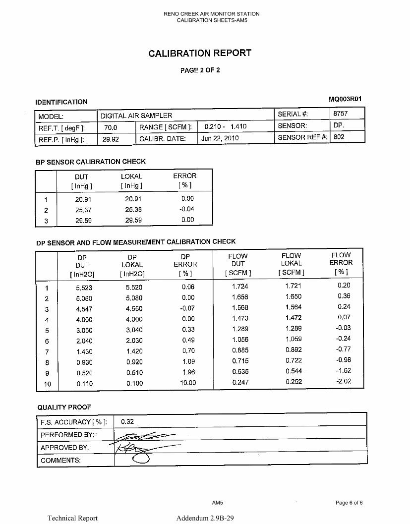
RENO CREEK AIR MONITOR STATION CALIBRATION SHEETS-AM5
AM5 Page 6 of 6
Technical Report Addendum 2.9B-29
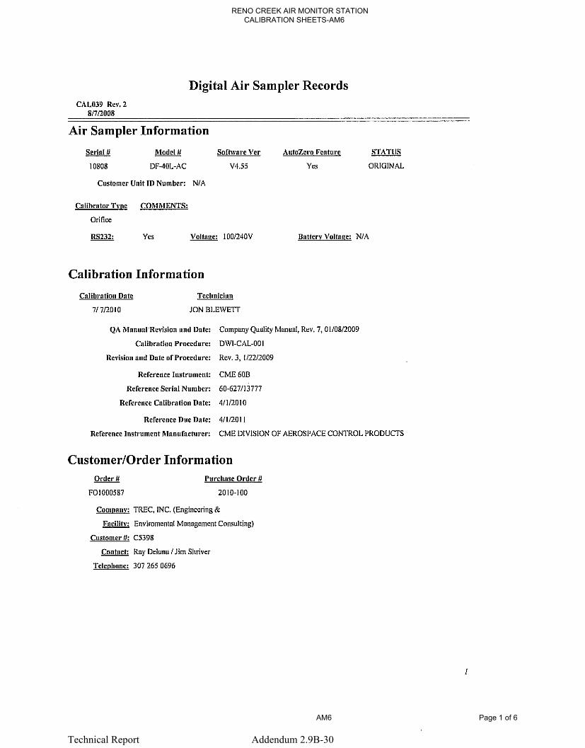
RENO CREEK AIR MONITOR STATION CALIBRATION SHEETS-AM6
AM6 Page 1 of 6
Technical Report Addendum 2.9B-30

RENO CREEK AIR MONITOR STATION CALIBRATION SHEETS-AM6
AM6 Page 2 of 6
Technical Report Addendum 2.9B-31

RENO CREEK AIR MONITOR STATION CALIBRATION SHEETS-AM6
AM6 Page 3 of 6
Technical Report Addendum 2.9B-32

RENO CREEK AIR MONITOR STATION CALIBRATION SHEETS-AM6
AM6 Page 4 of 6
Technical Report Addendum 2.9B-33
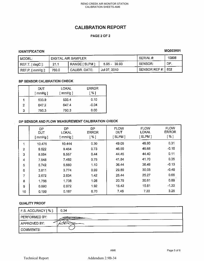
RENO CREEK AIR MONITOR STATION CALIBRATION SHEETS-AM6
AM6 Page 5 of 6
Technical Report Addendum 2.9B-34

RE
NO
CR
EE
K A
IR M
ON
ITOR
STA
TION
C
ALIB
RA
TION
SH
EE
TS-A
M6
AM
6P
age 6 of 6
Technical Report
Addendum
2.9B-35

License Application, Technical Report
September 2012 Addendum 2.9C-i
The Reno Creek ISR Project
ADDENDUM 2.9-C
Proposed Modification To Regulatory Guide 4.14 Pre-Operational Air Sampling Guidance

License Application, Technical Report
September 2012 Addendum 2.9C-ii
The Reno Creek ISR Project
WRITTEN REPORT BY DR. ROBERT MEYER,
TETRA TECH, INC.
SEPTEMBER, 2010
License Application, Technical Report
September 2012 Addendum 2.9C-1
The Reno Creek ISR Project
The purpose of this white paper is to suggest a method and rationale to extend the
recommended air sample filter replacement interval for air samplers used to establish pre-
operational radionuclide air concentration data for a proposed in situ recovery (ISR)
uranium facility in Wyoming. AUC at the Reno Creek ISR project (Reno Creek)
proposes to gradually extend the filter replacement period from one week to four weeks.
This proposed extension includes a protocol to evaluate the effect of the change over
time, to ensure that key data are not lost as a result of the extension.
The second portion of this document incorporates extracted text and tables from RG 4.14,
provided for convenience in evaluating this proposed change to USNRC guidance.
The rationale for this proposed extension in the air filter replacement interval is as
follows:
1) Currently available air samplers such as the F&J DF-40L to be used at the Reno
Creek site have proved to be very reliable in service at other Wyoming ISL
facilities. The samplers are computer-controlled to maintain factory-calibrated
flow rate over a range of dust loading conditions, and permanently record (via a
non-volatile-memory SD card) flow rate and date/time information on an hourly
basis over any sampling period of interest. This data storage capability allows the
operator to later determine the characteristics of sampler operation for any time
period during the filter exchange interval.
2) AUC plans to use 4-inch glass fiber filter media in all pre-operational air samplers
at the Reno Creek site, rather than the customary, much smaller 47 mm (1.85
inch) filters. Filter media collection efficiency characteristics of the 4 inch filters
are similar to those of the 47 mm filters. The 4 inch filters have an exposed
surface area approximately 4.6 times larger than that of the 47 mm filters. This
increased area, given the usual 25-30 lpm flow rate, allows the filters to be
operated for more than four times the standard collection interval when
considering potential dust build-up (dust loading) on the filter. In other words, the
4 inch filters may be exchanged at intervals more than four times longer than
those for 47 mm filters, when considering dust loading due to sampled air flow.

License Application, Technical Report
September 2012 Addendum 2.9C-2
The Reno Creek ISR Project
3) The samplers to be used at Reno Creek will either be line-powered or solar-
powered. In the latter case, the solar power systems are overdesigned to ensure
operation under extended low-solar-flux conditions (storm cloud cover e.g.). Both
power system types are known to be reliable under Wyoming field conditions.
4) The systems to be operated at Reno Creek will be managed as follows to ensure
that the proposed transition to extended sampling periods (up to four weeks vs.
one week) does not result in unexpected loss of data:
a. During the first four weeks of Reno Creek air sampler operation, filters
will be exchanged weekly.
b. During the next two months of operation, filters will be exchanged every
two weeks.
c. If no significant problems have been encountered during these first three
months of operation, filters will be exchanged monthly for the remainder
of the pre-operational year of air sampling. AUC plans to later propose to
the USNRC that they be allowed to continue a four-week sampling period
for operational air sampling at Reno Creek, assuming that this study is
successful.
d. During the weekly, biweekly and monthly pre-operational filter exchange
periods noted above, AUC and subcontractor staff will regularly inspect
the air samplers during site visits planned for other purposes, to evaluate
the samplers in terms of reliable operation. If significant problems are
observed, samplers exhibiting such problems will be repaired as
necessary, and the periods between filter exchange will then revert to a),
then b), then c) sampling intervals, as described above. In other words, a
sampler found to be unreliable will be repaired, then will be subject to a
restart of the proposed trial period.
All filters for a given quarter (three month) sampling period will be composited by
sampler, and sent to contract laboratory for analysis per RG 4.14 guidance.
AUC is proposing the above-modified air sampling filter replacement program to
increase efficiency of the overall program, and also to reduce the chance of filter loss or
other errors associated with the weekly filter exchange program.
AUC requests USNRC review and comment on the above proposal to gradually increase
air sampler filter change-outs from one-week to one-month intervals. In the interim, AUC

License Application, Technical Report
September 2012 Addendum 2.9C-3
The Reno Creek ISR Project
will install 4 inch filters on the Reno Creek air samplers, but will exchange those filters
on a weekly basis until NRC review of this proposal is complete.
Extracts from:
REGULATORY GUIDE 4.14 RADIOLOGICAL EFFLUENT AND
ENVIRONMENTAL MONITORING AT URANIUM MILLS
(Note: the following material has been extracted from RG 4.14 to summarize the
Guide’s discussion concerning pre-operational air sampling. Key text has been
highlighted. Information not related to pre-operational air sampling has not been
included).
****(Extracted material begins)****
“A. INTRODUCTION
Uranium mill operators are required by Nuclear Regulatory Commission (NRC)
regulations and license conditions to conduct radiological effluent and environmental
monitoring programs. Regulations applicable to uranium milling are contained in 10 CFR
Part 20, "Standards for Protection Against Radiation," and Part 40, "Domestic Licensing
of Source Material." For example, § 40.65, "Effluent Monitoring Reporting
Requirements," of 10 CFR Part 40 requires the submission to the Commission of
semiannual reports containing information required to estimate doses to the public from
effluent releases.
Information on radiation doses and the radionuclides in a mill's effluents and
environment both prior to and during operations is needed by the NRC staff:
1) To estimate maximum potential annual radiation doses to the public resulting
from effluent releases.
2) 2 To ascertain whether the regulatory requirements of the NRC (including 10
CFR Part 20 dose limits, release limits, and the "as low as is reasonably
achievable" requirement), mill license conditions, and the requirements of 40
CFR Part 190, "Environmental Radiation Protection Standards for Nuclear Power
Operations," have been met.
3) To evaluate the performance of effluent controls, including stabilization of active
and inactive tailings piles.

License Application, Technical Report
September 2012 Addendum 2.9C-4
The Reno Creek ISR Project
4) To evaluate the environmental impact of milling operations, both during
operations and after decommissioning.
5) To establish baseline data to aid in evaluation of decommissioning operations or
decontamination following any unusual releases such as a tailings dam failure.
This guide describes programs acceptable to the NRC staff for measuring and reporting
releases of radioactive materials to the environment from typical uranium mills.
The programs described in this guide are not requirements. Licensing requirements are
determined by the NRC staff on a case-by-case basis during individual licensing reviews.
Individual applicants or licensees may propose alternatives for new or existing
monitoring programs that need not necessarily be consistent with this guide. The
justification for such alternatives will be reviewed by the NRC staff, and the acceptability
of proposed alternatives will be determined on a case-by-case basis during individual
licensing reviews. For example, it is anticipated that operational monitoring programs
that do not include at least three continuous air samples at the site boundary will include
more extensive stack sampling and more sampling locations than are described in this
guide as well as meteorological data and additional environmental monitoring
requirements.
B. DISCUSSION
The radiation dose an individual receives can be determined only if the radionuclides to
which an individual is exposed are known. Therefore, monitoring programs should
provide accurate information on the specific radionuclides in effluents from a mill, its ore
piles, and its tailings retention system and in the surrounding environment.
Methods of sampling and analysis for the radionuclides associated with uranium milling
are discussed in sources listed in the bibliography. The listing of these documents is not
meant to be all inclusive, nor does it constitute an endorsement by the NRC staff of all of
the methods in all of the listings. Rather, these listings are provided as sources of
information to aid the licensee in developing a monitoring program.
The sampling program described below is divided into two parts: preoperational
monitoring and operational monitoring. Preoperational data is submitted to the NRC as
part of the application process. Operational data is reported as required by § 40.65 of 10
CFR Part 40 and specific license conditions and at times of license renewal.

License Application, Technical Report
September 2012 Addendum 2.9C-5
The Reno Creek ISR Project
C. REGULATORY POSITION
I. PREOPERATIONAL MONITORING
An acceptable preoperational monitoring program is described below and summarized in
Table I. At least twelve consecutive months of data, including complete soil sampling,
direct radiation, and radon flux data, should be submitted to the NRC staff prior to any
major site construction. A complete preoperational report with twelve consecutive
months of data should be submitted prior to beginning milling operations. Prior to the
start of local mining operations, if possible, monitoring data, including airborne radon
measurements, should be submitted to the NRC staff.
Applicants may propose alternatives to this preoperational program. However,
equivalent alternatives should be proposed for the operational program so that the
programs remain compatible.
1.1 Preoperational Sampling Program
1.1.1 Air Samples
Air particulate samples should be collected continuously at a minimum of three
locations at or near the site boundary. If there are residences or occupiable structures
within 10 kilometers of the site, a continuous outdoor air sample should be collected at or
near the structure with the highest predicted airborne radionuclide concentration due to
milling operations and at or near at least one structure in any area where predicted doses
exceed 5 percent of the standards in 40 CFR Part 190. A continuous air sample should
also be collected at a remote location that represents background conditions at the mill
site; in general, a suitable location would be in the least prevalent wind direction from the
site and unaffected by mining or other milling operations.
Normally, filters for continuous ambient air samples are changed weekly or more
often as required by dust loading.
The sampling locations should be determined according to the projected site and milling
operation. Preoperational sampling locations should be the same as operational locations.
The following factors should be considered in determining the sampling locations:

License Application, Technical Report
September 2012 Addendum 2.9C-6
The Reno Creek ISR Project
(1) average meteorological conditions (wind speed, wind direction, atmospheric
stability), (2) prevailing wind direction, (3) site boundaries nearest to mill, ore piles, and
tailings .piles, (4) direction of nearest occupiable structure (see footnotes of Tables I and
2), and (5) location of estimated maximum concentrations of radioactive materials.
Samples should be collected continuously, or for at least one week per month, for
analysis of radon-222. The sampling locations should be the same as those for the
continuous air particulate samples.
3. QUALITY OF SAMPLES
Provisions should be made to ensure that representative samples are obtained by use of
proper sampling equipment, proper locations of sampling points, and proper sampling
procedures (see bibliography). Air samples may be composited for analysis if (1) they
are collected at the same location and (2) they represent a sampling period of one
calendar quarter or less. Air samples should not be composited if (1) they represent a
sampling period of more than one calendar quarter, (2) they are from different sampling
locations, or (3) the samples are to be analyzed for radon-222. Samples collected for
analysis of radon-222 should be analyzed quickly enough to minimize decay losses.
Samples other than air samples should not be composited.
4. SOLUBILITY OF AIRBORNE RADIOACTIVE MATERIAL
Table II of Appendix B, "Concentrations in Air and Water Above Natural Background,"
to 10 CFR Part 20 lists separate values for soluble and insoluble radioactive materials in
effluents. In making comparisons between airborne effluent concentrations and the values
given in Table II of Appendix B to 10 CFR Part 20, the maximum permissible
concentrations for insoluble materials should be used.
5. LOWER LIMIT OF DETECTION
The lower limits of detection for stack effluent samples should be 10% of the appropriate
concentration limits listed in Table II of Appendix B to 10 CFR Part 20.
The lower limits of detection for analysis of other samples should be as follows:
U-natural, Th-230, Ra-226 in air: I x 10-16 uCi/ml; Pb-210 in air: 2 x I 0-15 uCi/ml

License Application, Technical Report
September 2012 Addendum 2.9C-7
The Reno Creek ISR Project
6. PRECISION AND ACCURACY OF RESULTS
6.1 Error Estimates
The random error associated with the analysis of samples should always be calculated.
The calculation should take into account all significant random uncertainties, not merely
counting error.
If the analyst estimates that systematic errors associated with the analysis are significant
relative to the random error, the magnitude of the systematic error should be estimated.
6.2 Calibration
Individual written procedures should be prepared and used for specific methods of
calibrating all sampling and measuring equipment, including ancillary equipment. The
procedures should ensure that the equipment will operate with adequate accuracy and
stability over the range of its intended use. Calibration procedures may be compilations
of published standard practices, manufacturers' instructions that accompany purchased
equipment, or procedures written in-house. Calibration procedures should identify the
specific equipment or group of instruments to which the procedures apply.
To the extent possible, calibration of measuring equipment should be performed using
radionuclide standards certified by the National Bureau of Standards or standards
obtained from suppliers who participate in measurement assurance activities with the
National Bureau of Standards (see Regulatory Guide 4.15).
Calibrations should be performed at regular intervals, at least semiannually, or at the
manufacturer's suggested interval, whichever is more frequent. Frequency of calibration
should be based on the stability of the system. If appropriate, equipment may be
calibrated before and after use instead of at arbitrarily scheduled intervals. Equipment
should be recalibrated or replaced after any repairs or whenever it is suspected of being
out of adjustment, excessively worn, or otherwise damaged and -not operating properly.
Functional tests, i.e., routine checks performed to demonstrate that a given instrument is
in working condition, may be performed using sources that are not certified by the
National Bureau of Standards.
6.3 Quality of Results
A continuous program should be prepared and implemented for ensuring the quality of
results and for keeping random and systematic uncertainties to a minimum. The

License Application, Technical Report
September 2012 Addendum 2.9C-8
The Reno Creek ISR Project
procedures should ensure that samples and measurements are obtained in a uniform
manner and that samples are not changed prior to analysis because of handling or because
of their storage environment. Tests should be applied to analytical processes, including
duplicate analysis of selected effluent samples and periodic cross-check analyses with
independent laboratories (see Regulatory Guide 4.15).
7. RECORDING AND REPORTING RESULTS
This section provides guidelines for recording all results. Reports submitted to NRC
should be prepared using these guidelines and the format shown in Table 3 of this guide.
7.1 Sampling and Analysis Results
7.1.1 Air and Stack Samples
For each air or stack sample, the following should be recorded:
1) Location of sample.
2) Dates during which sample was collected.
3) The concentrations of natural uranium, thorium230, radium-226, lead-210, and
radon-222 for all samples except stack samples.
4) The concentration of natural uranium, thorium230, radium-226, and lead-210 for
stack effluent samples.
5) The percentage of the appropriate 'concentration limit as shown in Table II of
Appendix B to 10 CFR Part 20.
6) The estimated release rate of natural uranium, thorium-230, radium-226, and lead-
210 for stack effluent samples.
7) 7. The flow rate of each stack.
7.1.4 Error Estimates
Reported results should always include estimates of uncertainty. The magnitude of the
random error of the analysis to the 95% uncertainty level should be reported for each
result. If significant, an estimate of the magnitude of the systematic error should also be
reported.
License Application, Technical Report
September 2012 Addendum 2.9C-9
The Reno Creek ISR Project
7.2 Supplemental Information
The following information should be included in each monitoring report submitted to
NRC:
1. Name of facility, location, docket number, and license number.
2. Description of sampling equipment and discussion of how sampling locations
were chosen.
3. Description of sampling procedures, including sampling times, rates, and
volumes.
4. Description of analytical procedures.
5. Description of calculational methods.
6. Discussion of random and systematic error estimates, including methods of
calculation and sources of systematic error.
7. The values of the lower limits of detection, along with a description of the
calculation of the lower limit of detection.
8. The values of maximum permissible concentration from Table II of Appendix
B to 10 CFR Part 20 used in any calculations.
9. Discussion of the program for ensuring the quality of results.
10. Description of calibration procedures.
11. Discussion of any unusual releases, including the circumstances of the release
and any data available on the quantities of radionuclides released.
7.3 Units
Radionuclide quantities should be reported in curies. Radionuclide concentrations should
be reported in microcuries per milliliter for air and water, microcuries per gram for soil
and sediment, and microcuries per kilogram for vegetation, food, or fish. Direct radiation
exposure rates should be reported in milliroentgens per calendar quarter.
Radon flux rates should be reported in picocuries per square meter per second. Stack flow
rates should be reported in cubic meters per second. (In the International System of Units,
a curie equals 3.7 x 10¹⁰ becquerels, a microcurie equals 3.7 x 10⁴ becquerels, and a
milliliter equals 10-6 cubic meters.) Estimates of random error should be reported in the
same units as the result itself. Estimates of systematic error should be reported as a
percentage of the result.

License Application, Technical Report
September 2012 Addendum 2.9C-10
The Reno Creek ISR Project
Note: The Commission has discontinued the use in 10 CFR Part 20 of the special curie
definitions for natural uranium and natural thorium (39 FR 23990, June 28, 1974).
Reports to the Commission should use units consistent with this change.
7.4 Significant Figures
Results should not be reported with excessive significant figures, so that they appear
more certain than they actually are. The reported estimate of error should contain no
more than two significant figures. The reported result itself should have the same number
of decimal places as the reported error.
7.5 Format
Reports should be submitted according to the format shown in Table 3. The term "not
detected," "less than the lower limit of detection (LLD)," or similar terms should never be
used. Each reported result should be a value and its associated error estimate, including
values less than the lower limit of detection or less than zero.
(Note: Non-applicable information has been removed from the above Table 1
image.)

License Application, Technical Report
September 2012 Addendum 2.9C-11
The Reno Creek ISR Project
(Stack sampling information has been removed from Table 3 image.)

License Application, Technical Report
September 2012 Addendum 2.9C-12
The Reno Creek ISR Project
(RG 4.14 bibliography image, page 2):

License Application, Technical Report
September 2012 Addendum 2.9C-13
The Reno Creek ISR Project
”
****(Material extracted from RG 4.14 ends.)****