acknowledgments - pca structurepoint reinforced concrete ... manual.pdf · ... analyzes and designs...
TRANSCRIPT

Acknowledgments
This microcomputer program is an enhanced version of an original Portland CementAssociation mainframe program written by K. M. Kripanarayanan. Many of theoriginal and fundamental algorithms are present in much of this microcomputerversion.
Additional enhancements, the manual and software design, and microcomputerprogramming were created and performed by the Computer Programs MarketingDepartment of the Portland Cement Association.
While the Portland Cement Association has taken every precaution to utilize theexisting state of the art and to assure the correctness of the analytical solutions anddesign techniques used in this program, the responsibilities for modeling thestructure, inputting data, applying engineering judgement to evaluate the output, andimplementing engineering drawings remain with the structural engineer of record.Accordingly, Portland Cement Association does and must disclaim any and allresponsibility for defects or failures of structures in connection with which thisprogram is used.
© 1999 Portland Cement Association. All rights reserved.
MS-DOS is a trademark of Microsoft, Inc.Microsoft and Windows are registered trademarks of the Microsoft Corporation.

ADOSS Features
ADOSS, the microcomputer version of PCA’s mainframe program-Analysis andDesign of Slab Systems (ADOSS), analyzes and designs an interior or exterior two-dimensional equivalent frame according to the relevant provisions of the Code.ADOSS provides the following three options: the Strength Design Method, theLimit States Method, and the Alternate Design Method. The program handles bothround and rectangular columns, while allowing for user-controlled fixity conditionsof all supports. The height of each column may differ, and the slab depth may varyfrom span to span. Lateral loads may be input into the program either asconcentrated story loads, or as joint moments from STMFR II (PCA’s frame analysisprogram) or from any other analysis program. The output includes the analysis ofcenterline and design moments and shears, punching shear stresses, cracked sectiondeflection, and torsion design of transverse beams. Based on a realistic selection ofreinforcement and bar lengths, the program provides a quantity estimate forconcrete, reinforcement, and formwork.
Model elements and vertical loads acceptable to ADOSS
1 The Code refers to either the ACI 318-95 Code, or the CSA Standard A23.3-94.

Table of Contents
Installing the Program
Installing ADOSS ...........................................................................................................1-1
Running ADOSS ............................................................................................................1-2
System Requirements .....................................................................................................1-2
Backing up the Original ADOSS Set ............................................................................1-3
Default Options Dialog Box ...........................................................................................1-3
Setting the Default Data Directory .................................................................................1-3
Customer Information ....................................................................................................1-5
File Transfer and Change Disk Dialog Boxes ................................................................1-5
View README Document ............................................................................................1-5
Running ADOSS ............................................................................................................1-6
Method of Solution
Geometric Checks ...........................................................................................................2-1
Code Checks ...................................................................................................................2-2
Drop Panel Dimensions ....................................................................................2-2
Column Capital Dimensions ............................................................................2-4
T-Beam Dimensions .........................................................................................2-4
Waffle Rib Dimensions ....................................................................................2-5
Minimum Slab Thickness of Flat Plate, Flat Slab and Beam-Supported Slab Systems ....................................................................................................2-6
Minimum Thickness for Waffle Slab Systems .................................................2-8
Minimum Thickness of Continuous Beams and One-Way Slab Systems .......2-8
Table of Contents 1

Special Considerations for Waffle Slabs ........................................................................2-9
Material Properties .......................................................................................................2-11
The Equivalent Frame Method .....................................................................................2-13
Stiffness Characteristics ................................................................................2-14
Slab Beams ....................................................................................................2-14
Columns ........................................................................................................2-17
Loading .........................................................................................................................2-24
Self-Weight .....................................................................................................2-25
Superimposed Loading ...................................................................................2-25
Lateral Loading ..............................................................................................2-26
Loading Patterns .............................................................................................2-29
Column and Middle Strip Widths .................................................................................2-33
Design Moments ...........................................................................................................2-35
Shear Analysis of Slabs ................................................................................................2-42
Critical Section for Interior Supports of Interior Frames ..............................2-43
Critical Section for Exterior Supports of Interior Frames .............................2-44
Critical Section for Interior Supports of Exterior Frames .............................2-44
Critical Section for Exterior Supports of Exterior Frames ............................2-44
Computation of Allowable Shear Stress at Critical Section ..........................2-46
Computation of Factored Shear Force at Critical Section .............................2-47
Computation of Unbalanced Moment at Critical Section ..............................2-49
Computation of Shear Stresses at Critical Section ........................................2-51
Shear Analysis of Longitudinal Beams ........................................................................2-52
Shear and Torsion Analysis of Transverse Beams ........................................................2-55
Area of Reinforcement .................................................................................................2-59
2 Table of Contents
ADOSS Graphics

Reinforcement Selection ...............................................................................................2-61
Additional Reinforcement at Support ..........................................................................2-64
Additional Information in Span ....................................................................................2-66
Deflection Calculation ..................................................................................................2-66
Deflections of Continuous Beams and One Way Slabs ...............................................2-70
Cracking .........................................................................................................2-70
Deflection Computations ...............................................................................2-73
Material Quantities .......................................................................................................2-74
Menu Descriptions
ADOSS Graphics Menu Descriptions ............................................................................3-1
The File Menu ..................................................................................................3-1
The Input Menu ................................................................................................3-4
The View Menu ................................................................................................3-6
The Design Menu .............................................................................................3-8
The Options Menu ...........................................................................................3-9
The Window Menu .........................................................................................3-10
The Help Menu ..............................................................................................3-11
The Control Menu ..........................................................................................3-12
Operating the Program
Main Screen Components ...............................................................................................4-1
Title Bar ............................................................................................................4-1
Control Menu ...................................................................................................4-1
Menu Line ........................................................................................................4-2
Table of Contents 3
ADOSS Graphics

Dialog Boxes ....................................................................................................4-3
Edit Boxes ........................................................................................................4-3
Menu and Dialog Controls ...............................................................................4-4
Enabled/Disabled Options ................................................................................4-4
Radio Buttons ...................................................................................................4-4
Check Boxes .....................................................................................................4-4
Push Buttons .....................................................................................................4-5
Working With Data Files ................................................................................................4-5
Creating a New Data File .................................................................................4-5
Saving Your Data ..............................................................................................4-6
Opening an Existing Data File .........................................................................4-7
Modeling a Building Floor System ................................................................................4-8
Including Labels with the Output ....................................................................4-8
Creating the Floor System ...............................................................................4-9
Using the General Information Command .....................................................4-10
Defining the Material Properties ...................................................................4-12
Defining Reinforcement Parameters ..............................................................4-14
Defining the Structure Geometry ..................................................................4-16
Defining the Slab Geometry ..........................................................................4-18
Defining the Rib Geometry ...........................................................................4-21
Defining Longitudinal Beam Geometry ........................................................4-22
Defining Column and Capital Geometry .......................................................4-26
Defining Drop Geometry ...............................................................................4-29
Defining Transverse Beam Geometry ............................................................4-31
Changing the Column Fixity ..........................................................................4-33
4 Table of Contents
ADOSS Graphics

Specifying Loads on the Floor System ........................................................................4-34
Specifying Uniform Surface Loads ...............................................................4-34
Specifying Partial Surface, Concentrated, and Moment Loads .....................4-35
Specifying Lateral Loads ...............................................................................4-38
Changing the Live Load Reduction Factor ....................................................4-40
Changing the Load Factors ............................................................................4-41
Applying More Lateral Load to the Column Strip ........................................4-42
Viewing the Input Data .................................................................................................4-43
Viewing the Floor System with the Scale ......................................................4-43
Zooming in on the System .............................................................................4-43
Changing the Isometric View Angle ..............................................................4-44
Viewing Specific Member Types ...................................................................4-45
Viewing Specific Load Types ........................................................................4-46
Designing ......................................................................................................................4-47
Designing the Floor System ...........................................................................4-50
Designing the Column ...................................................................................4-50
Viewing and Printing Design Results ............................................................4-52
Viewing and Printing the Results ...................................................................4-52
Viewing and Printing Shear and Moment Diagrams .....................................4-53
Viewing and Printing the Deflected Shapes ..................................................4-55
Customizing ADOSS ....................................................................................................4-56
Changing the Background Color ...................................................................4-56
Changing the Member Colors ........................................................................4-57
Changing the Load Colors .............................................................................4-58
Changing the Default Units and Code ...........................................................4-59
Table of Contents 5
ADOSS Graphics

Changing the Default Data Directory ............................................................4-60
Changing the Margins of a Screen Print ........................................................4-60
Manipulating the Windows ...........................................................................................4-61
Working with Windows ..................................................................................4-62
Getting On-Line Help ...................................................................................................4-63
Obtaining the ADOSS Version Number .......................................................................4-65
Output Description
Output Elements .............................................................................................................5-1
Program Version .............................................................................................................5-2
Description of Input Echo ..............................................................................................5-2
CODE Checks .................................................................................................................5-3
Analysis Elements ..........................................................................................................5-3
Design Elements .............................................................................................................5-7
6 Table of Contents
ADOSS Graphics

Conversion Factors
Conversion Factors – U.S. to SI .......................................................................A-1
U.S. Bar Sizes...................................................................................................A-2
SI Bar Sizes ......................................................................................................A-3
References
References .......................................................................................................B-1
Examples
Example 1, Flat Slab ........................................................................................C-2
Example 2, Beam-Supported Slab .................................................................C-19
Example 3, Continuous Beam........................................................................C-40
Table of Contents 7
ADOSS Graphics

Chapter 1
Installing the Program
Installing ADOSS
1. Execute Windows and insert the ADOSS diskette into the proper floppydisk drive.
2. From the Program Manager File menus, select Run.
3. Enter a:pcasetup or b:pcasetup (depending on the drive thediskette is in) in the COMMAND LINE text box, then choose OK.
4. The setup program prompts you for the directory where ADOSS is to beinstalled. The default directory is C:\ADOSS. To specify and alternatedirectory, type in the directory complete with a drive letter. If thedirectory does not exist, the setup program creates it. Press ENTER orchoose INSTALL.
5. The DEFAULT OPTIONS dialog box appears next. This allows you tocustomize ADOSS by setting the units of measure (US or Metric) and theCode (ACI or CSA). These defaults are saved in the PCAPROGS.INIfile, located in the WINDOWS directory.
6. The CUSTOMER INFORMATION dialog box appears next asking for the firmname, city, and state. Be sure to press TAB to move to the CITY and STATE
text boxes. Press ENTER or choose OK when done.
7. The setup program begins to copy files from the installation drive to thedestination drive. Once the file transfer is done, setup adds the“ADDOSS” icon to the Program Manager. A “PCA Programs” groupbox is created (if one does not exist) and the “ADOSS” icon is added.
8. After the setup program displays a successful installation message, thelast dialog box displayed ask whether you would like to view theREADME.TXT file. This file contains information supplemental to themanual.
Installing ADOSS V6.0 1-1

Running ADOSS
To execute ADOSS from within Windows:
• Select the “ADOSS” icon from within the “PCA Programs” group windowand press ENTER (or simply double-click on the icon).
To execute ADOSS from the DOS prompt:
• Change the directory to where the program is installed, type in ADOSS and press ENTER. This will execute Windows and load the ADOSS program as the application program.
System Requirements
To use ADOSS, a personal computer with the following hardware and softwareconfiguration is needed.
• MS-DOS operating system version 5.0 or higher.
• Microsoft Windows version 3.1 (running in Enhanced mode).
Minimum requirements:
• 4.0 MB of RAM memory with 1 M of free conventional memory.
• One floppy disk drive.
• A hard disk with at least 2.0 MB of free space.
• A monitor supported by Windows V3.1.
• A mouse or other pointing device supported by Windows V3.1.
Recommended Options:
• A printer supported by Windows V3.1
• A math co-processor.
1-2 Installing ADOSS V6.0
ADOSS Graphics

Backing up the Original ADOSS Set
Before you install ADOSS, take time out to make a backup copy of the ADOSS disk.The license agreement states that you are allowed to make one backup copy of thedisk. This backup set should be safely stored away and used only if the original diskis damaged in any way.
IMPORTANT: The license agreement states that only one backup could be made.This set is strictly a backup copy and it is not intended to be used on any othermachine.
Default Options Dialog Box
This dialog box allows you to customize ADOSS to your needs by setting twodefault options; units of measure (US or SI) and code (ACI or CSA). This willeliminate the task of specifying these options for each ADOSS session.
These defaults are saved in the file PCAPROGS.INI located in the Windowsdirectory. Each time ADOSS is executed, PCAPROGS.INI is read by ADOSS andthe information is incorporated in the session. You can also change these settings inADOSS by using the Default Unit/Codes command of the Options menu.
Note: Selecting Cancel will set the units and code options to the default values.The default values are initially set to US units and ACI code.
Setting the Default Data Directory
PCA Setup will prompt you for the default data directory. The default data directoryis the directory where ADOSS will look for data when you elect to open a data file.The ADOSS default data directory is <ADOSS Directory>\DATA. Figure 1-1displays the default data directory dialog box.
Installing ADOSS V6.0 1-3
ADOSS Graphics

Figure 1-1 Default Data Directory dialog box
To use the default directory, press Enter or select Ok . If the data directory doesnot exist, it will be created. The default data directory will be written to thePCAPROGS.INI file. You can change the default data directory in ADOSS by usingthe Default Data Directory command from the Options menu.
A different directory can be used for the data other than that given. Use thebackspace key and enter the new directory where you want ADOSS to look for data.If this directory does not exist, it will be created.
Note: Selecting Cancel will leave the default data directory unspecified. Thisapproach is practical to the user who has multiple data directories and who doesnot want to specify a particular data directory. If the default data directory is leftunspecified, ADOSS assumes the current directory as the default data directory.
1-4 Installing ADOSS V6.0
ADOSS Graphics

Customer Information
Record your firm name, city, and state. Be sure to tab to the city and state edit boxesinstead of pressing enter. By selecting Ok or pressing Enter , you are confirmingyour choices. By selecting Cancel , changes made to this dialog box will not besaved.
If you select Enter a customer information verification box will be displayedprompting you to confirm your choices. Select Enter to save the information orselect Change if you want to edit the information displayed.
Note: Press Enter only after all the edit boxes are filled in.
File Transfer and Change Disk Dialog Boxes
PCA Setup will begin to copy files from the drive the ADOSS Disk was placed into the ADOSS Directory. The source path and destination path are displayed in thisdialog box along with a file transfer progress scale.
View README Document
After PCA Setup displays a successful installation message, the last dialog boxdisplayed will ask whether you would like to view the ADOSS README file.
This is a good opportunity to read this file which contains information supplementalto the manual. Selecting Yes , will cause PCA Setup to execute the viewingutility, PCA View, and load the README file. Selecting No will simply terminatethe PCA Setup program.
IMPORTANT: A message box will appear acknowledging a successful installationof ADOSS V7.00. If PCA Setup modified the AUTOEXEC.BAT file, reboot yoursystem in order for the changes made to the AUTOEXEC.BAT file to take effect. IfPCA Setup did not modify the AUTOEXEC.BAT file, then you are ready to runADOSS V7.00.
Installing ADOSS V6.0 1-5
ADOSS Graphics

Running ADOSS
There are a number of ways to execute ADOSS from within Windows. One way isto select the ADOSS Icon in the “PCA Programs” group window from within theProgram Manager and press Enter . Another way is to select the Run commandunder the File menu in the Program Manager. A dialog box will be displayedprompting for a command line. Type “ADOSS” in the edit box and press Enter .Lastly, you can execute ADOSS from the File Manager by selecting an ADOSS datafile with an .ADS extension and pressing Enter . PCA Setup creates thisapplication association between the application program, ADOSS, and the data fileswhich have the .ADS extension.
1-6 Installing ADOSS V6.0
ADOSS Graphics

Chapter 2
Method of Solution
The user should be aware of the assumptions made by the program during thedesign stage. These include details regarding loading, strip widths, reinforcementselection, deflection computations, material quantities, etc.
Geometric Checks
The ADOSS program provides geometric to avoid an analysis with an inconsistentsystem. The dimensions of the slabs, drops, and column capitals are checked andmodified to produce a legitimate system.
If the slab cantilever length is less than one-half the column dimension in thedirection of analysis c1, or less than the extension of the transverse beam into thecantilever, the cantilever length will be increased to the larger of these two lengths.If the slab width is less than one-half the column dimension transverse to thedirection of analysis, c2, or less than one-half the longitudinal beam width, the slabwidth will be increased to the larger of these two widths.
If the drop panel lengths extend beyond the end of the slab cantilevers, the droppanel lengths will be reduced so that they extend only to the cantilever tip. The droppanel will be shifted forward or backward in the transverse direction when the slabstrip width on either side of the column is less than one-half the drop panel width.
If a column capital contains an extension/depth ratio greater than 1, the extensionwill be set equal to the capital depth. If, by drawing lines extending the columncapital through the drop or beam to the underside of the slab, the column capitalextension falls outside the edge of the drop or beam at the slab soffit, the extensionwill be modified such that these lines extend only up to the edge of the drop or beamat the slab soffit (Figure 2-1).
Method of Solution 2-1
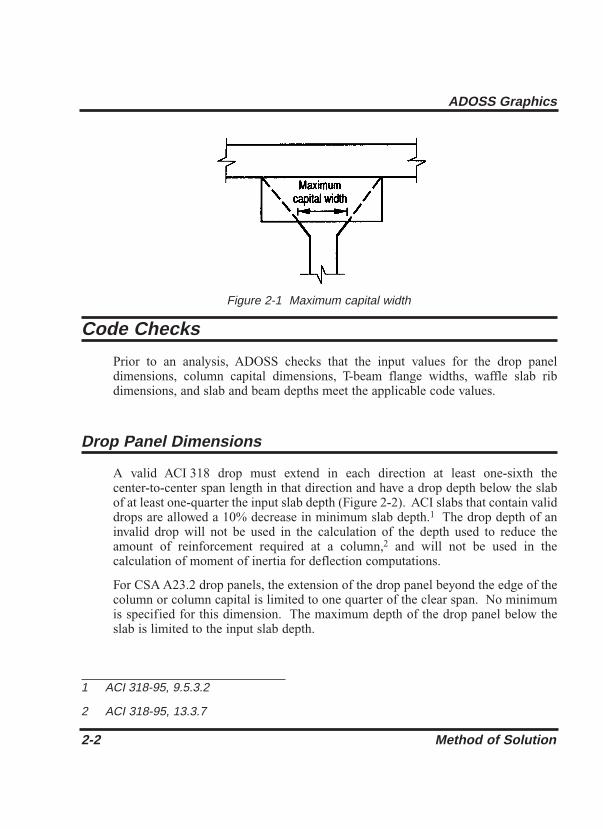
Figure 2-1 Maximum capital width
Code Checks
Prior to an analysis, ADOSS checks that the input values for the drop paneldimensions, column capital dimensions, T-beam flange widths, waffle slab ribdimensions, and slab and beam depths meet the applicable code values.
Drop Panel Dimensions
A valid ACI 318 drop must extend in each direction at least one-sixth thecenter-to-center span length in that direction and have a drop depth below the slabof at least one-quarter the input slab depth (Figure 2-2). ACI slabs that contain validdrops are allowed a 10% decrease in minimum slab depth.1 The drop depth of aninvalid drop will not be used in the calculation of the depth used to reduce theamount of reinforcement required at a column,2 and will not be used in thecalculation of moment of inertia for deflection computations.
For CSA A23.2 drop panels, the extension of the drop panel beyond the edge of thecolumn or column capital is limited to one quarter of the clear span. No minimumis specified for this dimension. The maximum depth of the drop panel below theslab is limited to the input slab depth.
2-2 Method of Solution
ADOSS Graphics
1 ACI 318-95, 9.5.3.2
2 ACI 318-95, 13.3.7

Figure 2-2 Valid drop dimensions
Figure 2-3 Excess drop depth
Method of Solution 2-3
ADOSS Graphics

If the valid drop depth is greater than one-quarter the distance from the edge of thedrop panel to the face of the column or column the excess depth will not beconsidered in the calculation of the effective depth used to reduce the amount ofreinforcement required at a column (Figure 2-3).3
The input drop dimensions will be used for self-weight computations, whencomputing slab stiffness and to determine moments and shears when computingpunching shear around a column.
Column Capital Dimensions
If a column capital contains an extension/depth ratio greater than 1, the extensionwill be set equal to the capital depth. If, by drawing lines extending the columncapital through the drop or beam to the underside of the slab, the column capitalextension falls outside the edge of the drop or beam at the slab soffit, the extensionwill be modified such that these lines extend only up to the edge of the drop or beamat the slab soffit (Figure 2-1).
The modified column capital dimensions will be used when computing columnstiffness.
T-Beam Dimensions
For the ACI Code the effective T-beam flange width will not exceed one-quarter thebeam span length for the ACI code. For beams that have slabs on both sides, themaximum flange overhang will not exceed eight times the slab thickness or the inputslab width on that side. For beams that have slab on one side only, the maximumflange overhang will not exceed one-twelfth the beam span length, six times the slabthickness, or the input slab width on the overhang side (Figure 2-4)4
For the CSA Standard the effective flange width of T-beams is based on theoverhanging flange widths on each side of the web which are not greater than 1/10of the span length, 12 times the slab thickness or 1/2 the clear distance to the nextweb. Where a slab exists on only one side of the beam, the overhanging flangewidth is limited to 1/12 of the span of the beam, 6 times the slab thickness, and 1/2the clear distance to the next web.
2-4 Method of Solution
ADOSS Graphics
3 ACI 318-95, 13.3.7.3; CSA A23.3-94, 13.11.6
4 ACI 381-95, 8.10.2-8.10.3; CSA-A23.3-94, 10.3.3-10.3.4

These T-beam dimensions will be used for computing the stiffness. The entire slabwidth, however, will be used when computing self-weight and superimposed surfacedead and live loads.
Waffle Rib Dimensions
Waffle slab rib dimensions will be considered valid if the rib width is at least 4 in.,the depth is no more than 3-1/2 times the rib width, and the clear spacing betweenribs does not exceed 30 in. (Figure 2-5). When valid ribs exist, the ACI code permitsthe nominal concrete shear strength, Vc, to be increased by 10%.5
Figure 2-4 Allowable T-beam flange widths
Method of Solution 2-5
ADOSS Graphics
5 ACI 318-95, 8.11

Figure 2-5 Valid rib dimensions
Minimum Slab Thickness of Flat Plate, Flat Slab and Beam-Supported Slab Systems
For ACI 318-95 Code, the minimum thickness of slabs with or without interiorbeams spanning between supports and having a ratio of long to short span notexceeding 2 is:6
Eq. 2-1
but not less than
Eq. 2-2
For CSA A23.3-94
l (0.8 + )36 + 9ß
200,000h = am > 2.0
nfy
l (0.8 + )36 + 5ß (α – 0.2)
200,000h = 0.2 < am ≤ 2.0
nfy
m
2-6 Method of Solution
ADOSS Graphics
6 318-95, 9.5.3.3; CSA-A23.3-94, 13.3.5
l (0.6 + fy/1000)
30 + 4ßamhs ≥ am taken ≤ 2.0
n

where
ln = clear span in the direction of analysis.
ß = ratio of the clear spans in long to short direction.
am = average value of a, the ratio of flexural stiffness of a beamsection to the flexural stiffness of a width of slab boundedlaterally by centerlines of adjacent panels on either side ofthe beam, for all beams supporting the edges of a slab panel.
For the design of ACI slabs without beams spanning between supports the minimumthickness shall conform to ACI 318 Table 9.5(c) For flat slabs that contain validdrops, Table 9.5 (c) reduces the minimum thickness by approximately 10%.7 (SeeFigure 2-2).
The minimum depth in a span that contains a discontinuous edge will be increasedby 10% if the edge beam provided has a stiffness ratio, a, of less than 0.80.8 Thefirst and last spans are considered to contain a discontinuous edge as well as a spanthat contains an exterior edge.
For the CSA Standard the minimum thickness is:
a) for flat plates and slabs with column capitals
hs > ln (0.6 + fy /1000)/30
b) for slabs with drop panels
Eq. 2-3
where Xd / (ln/2) is the smaller of the values determined in the twodirections, Xd shall not be taken greater than ln/4 and hd - hs shall not begreater than hs.
30 [1+ ( )( )]
l (0.6 + f /1000)h ≥
n
l n
s h –d2xd hs
hs
y
Method of Solution 2-7
ADOSS Graphics
7 ACI 318-95, 9.5.3.2
8 ACI 318-95, 9.5.3.3 (d)

For flat plate systems, the minimum allowable thickness can in no case be less than5.0 in. For two-way flat slab systems with drops, described above, the minimumallowable thickness can in no case be less than 4.0 in., otherwise 5.0 in.9 Forsupported slab systems supported by beams with an am greater than or equal to 2.0,the minimum allowable thickness can in no case be less than 3.5 in., otherwise 5.0 in.10
is taken on the minimum allowable thickness.
A message will be printed with the output showing the required slab depth for anyspan where the depth does not meet or exceed code requirements.
Minimum Thickness for Waffle Slab Systems
The minimum slab thickness allowed for waffle slabs is one-twelfth the clear ribspacing, or 2 in.11
A message will be printed with the output showing the required slab depth for thesystem if the depth does not meet or exceed code requirements.
Minimum Thickness of Continuous Beams and One-Way Slab Systems
The minimum depth of continuous beam systems and one-way slabs, made ofnormal weight concrete and using Grade 60 reinforcing bars below whichdeflections must be computed is shown in Table 2.1.12 Note: l in Table 2.1 iscenter-to-center span lengths for ACI 318 and clear span lengths for CSA-A23.3.
For concrete density in the range of 90–120 pcf, the above minimum thicknesses areincrease by (1.65–0.005w) but not less than 1.09, where w is the concrete density inpcf. For fy other than 60 ksi, the minimum thicknesses are increased by (0.4 +fy/100).13
A message will be printed with the output showing the required beam or slab depthfor any span where the depth does not meet or exceed code requirements.
2-8 Method of Solution
ADOSS Graphics
9 ACI 318-95, 9.5.3.2
10 ACI 318-95, 9.5.3.3
11 ACI 318-95, 8.11.6.1
12 ACI 318-95, 9.5.2.1; CSA-A23.3 94, 9.8.5.2, Table 9-1
13 ACI 318-95, Table 9.5(a)

Table 2.1 – Minimum Thickness of Continuous Beam andOne-Way Slab Systems
Special Considerations for Waffle Slabs
For the purposes of analysis and design, ADOSS replaces the waffle with solid slabsof equivalent moment of inertia, weight, and punching shear resistance.
The equivalent thickness based on system weight is used to compute the systemself-weight. This thickness, hw, is given by:
Eq. 2-4
where
Vmod = the volume of one waffle module.
Amod = the plan area of one waffle module.
The equivalent thickness based on moment of inertia is used to compute slabstiffness. The ribs spanning in the transverse direction are not considered in thestiffness computations. This thickness, hMI, is given by:
Eq. 2-5hMI = ( )12MI
Brib
1/3
hv =Vmod
Amod
Method of Solution 2-9
ADOSS Graphics
Minimum Thickness, h
Interior Span First and Last Other Interior CantileverFloor System of a Three Interior Span Spans
Span System
Continuous l/16 l/18.5 l/21 l/8Beams
One-Way l/20 l/24 l= /28 l/16Slabs

where
MI = moment of inertia of one waffle section between centerlinesof ribs.
brib = the center-to-center distance of two ribs (clear rib spacingplus rib width).
The drop depth for waffle slab systems is set equal to the rib depth; therefore, aninput drop depth of 0 is sufficient. The equivalent drop depth based on moment ofinertia, dMV, is given by:
ddrop = hslab + hrib – hMI Eq. 2-6
where
hslab = overall thickness of slab.
hrib = rib depth below slab.
hMI = equivalent slab thickness based on moment of inertia.
A drop depth entered for a waffle slab system other than 0 will be added to dMV, thusextending below the ribs.
The equivalent thickness based on shear area is used to compute the area of concretesection resisting shear transfer, Ac around the drop. The equivalent slab thickness,hV, used to compute Ac, is given by:
Eq. 2-7
where:
Arib = the entire rib area below the slab plus the slab thicknessminus the distance to the reinforcement centroid, dreinf,within the rib width, (i.e., the slab depth between the ribs isnot considered as contributing to shear resistance.)
brib = the center-to-center distance of two ribs (clear rib spacingplus rib width).
dreinf = the distance to reinforcement centriod from the slab top atthe support.
hv = + dreinfArib
brib
2-10 Method of Solution
ADOSS Graphics

Material Properties
By entering the concrete density and compressive strength of the members, defaultvalues for the other concrete properties are determined. The slab, column, and beammembers may have different concrete properties.
The density of concrete is used to determine the type of concrete, modulus ofelasticity, and self-weight.
For the ACI Code, the concrete type is used to determine the default value of fct, theaverage split tensile strength of concrete. The concrete type is determined inaccordance with Table 2.2.
Note: The CSA Standard does not use fct
Table 2.2 –Default Concrete Types
Once fc the compressive strength of concrete, is input, various parameters are set totheir default values.
The modulus of elasticity is computed as:14
Eq. 2-8Ec= 33w1.5 fc
Method of Solution 2-11
ADOSS Graphics
Density (w)
pcf kg/m3Type
w ≥ 130 w ≥ 2000 Normal
105 < w < 130 1700 < w < 2000 Sand-Lightweight
w ≤ 105 w ≤ 1700 All-Lightweight
14 ACI 318-95, 8.5.1; CSA-A23.3-p4, 8.6.2.2

where
w = the density of the concrete.
For CSA A23.3
The square root of fc is limited to 100 psi for the computation of shear strengthprovided by concrete, Vc, and development lengths.15
Eq. 2-9
Equations 2-8 and 2-9 are used internally and cannot be modified.
The average split tensile strength is used to compute the modulus of rupture andreinforcement development lengths. For normal weight concrete, the default valueof fct used by ADOSS is set equal to:16
Eq. 2-10
In no case will fct/6.7 exceed . fct will be modified according to the concretetype. Table 2.3 shows the default values for fct for different concrete types. Nointerpolation is performed for partial sand replacement.
Table 2.3 – Default Average Splitting Tensile Strength
fc
fcfct = 6.7
fcfct = 6.7
2-12 Method of Solution
ADOSS Graphics
Type fct
Normal 6.7
Sand-Lightweight (0.85) 6.7
All-Lightweight (0.75) 6.7 fc
fc
Ec= (3300 fc + 6900)(––––)1.5g2300
15 ACI 318-95, 11.1.2
16 ACI 318-95, 9.5.2.3

The modulus of rupture is used to determine the cracking moment when computingthe effective moment of inertia for deflection computations. The default value of fr,modulus of rupture, is set equal to:
For ACI 318
fr = 1.12 fct Eq. 2-11
If fct is that given in Eq. 2-10, Eq. 2-11 is equal to:17
Eq. 2-12
For CSA A23.3 for beams and columns and for slabs.
There is no limit imposed on fr. Entering a large value of fr will produce deflectionsbased on gross properties, (i.e., uncracked sections).
The default values for the longitudinal reinforcement yield strength, fy, and shearreinforcement yield strength, fyv, if applicable, are set equal to 60 ksi (400 MPa).
The Equivalent Frame Method
The equivalent frame method, as described in the Code,18 is used by ADOSS forboth analysis and design.
The Code specifies procedures for the analysis and design of slab systemsreinforced for flexure in more than one direction, with or without beams betweenthe supports. A two-way slab19 system, including the slab and its supporting beams,columns, and walls may be designed by either of the following procedures:
• The Direct Design Method
• The Equivalent Frame Method
fcfr = 0.62
fcfr = 0.6
fcfr = 7.5
Method of Solution 2-13
ADOSS Graphics
17 ACI 318-95, Eq.9-9; CSA A23.3-94, 8.6.4 & 13.3.6
18 ACI 318-95, Chapter 13; CSA A23.3-94, Clause 13
19 Implies a slab supported by isolated supports which permits the slab to deflect in two orthogonal directions.

ADOSS uses the Equivalent Frame Method of analysis. It should be noted that thismethod is based on extensive analytical and experimental studies conducted at theUniversity of Illinois. Note also that there are no restrictions on the number of slabspans or on dead-to-live load ratios in this method of analysis.
The first step in the frame analysis is to divide the three-dimensional building intoa series of two-dimensional frames extending to the full height of the building.Horizontal members for each frame are formed by slab strips as shown in Figure2-6. For vertical loads, each story (floor and/or roof) may be analyzed separatelywith the supporting columns being considered fixed at their remote ends. (Figure2-7).
Stiffness Characteristics
The stiffnesses and carryover factors are determined for the horizontal members(the slab beams) and the vertical members (the equivalent columns) using columnanalogy, after dividing each member into 220 equal segments.
Slab Beams
The moment of inertia of the slab beam elements between the faces of the columns(or column capitals) is based on the uncracked section of the concrete includingbeams or drop panels. The moment of inertia from the face of the column (or capital)to the centerline of the column (or capital) is considered finite and is dependent onthe transverse dimensions of the panel and support. This reduced stiffness (ascompared to the infinite stiffness assumed in previous codes) is intended to softenthe slab at the joint to account for the flexibility of the slab away from the support.This is consistent with provisions of the Code.20 Figure 2-8 shows the changes instiffness between a slab, and a drop panel, and a column (or capital).
2-14 Method of Solution
ADOSS Graphics
20 ACI 318-95, 13.7.3; CSA-A23.-94, 13.9.2.3

Figure 2-6 Design strips
Figure 2-7 Analytical model for vertical loads for a typical story
Method of Solution 2-15
ADOSS Graphics
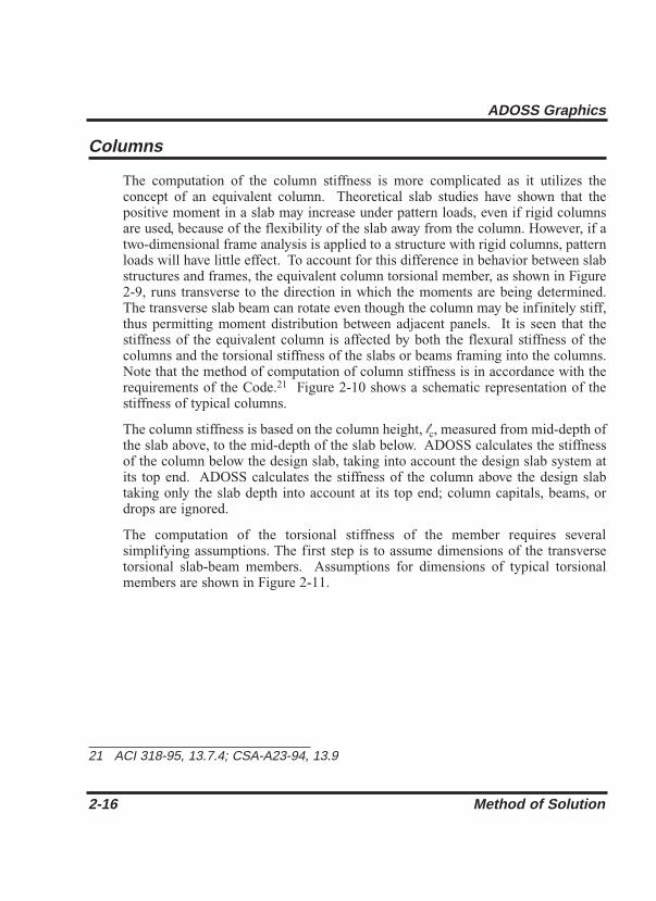
Columns
The computation of the column stiffness is more complicated as it utilizes theconcept of an equivalent column. Theoretical slab studies have shown that thepositive moment in a slab may increase under pattern loads, even if rigid columnsare used, because of the flexibility of the slab away from the column. However, if atwo-dimensional frame analysis is applied to a structure with rigid columns, patternloads will have little effect. To account for this difference in behavior between slabstructures and frames, the equivalent column torsional member, as shown in Figure2-9, runs transverse to the direction in which the moments are being determined.The transverse slab beam can rotate even though the column may be infinitely stiff,thus permitting moment distribution between adjacent panels. It is seen that thestiffness of the equivalent column is affected by both the flexural stiffness of thecolumns and the torsional stiffness of the slabs or beams framing into the columns.Note that the method of computation of column stiffness is in accordance with therequirements of the Code.21 Figure 2-10 shows a schematic representation of thestiffness of typical columns.
The column stiffness is based on the column height, lc, measured from mid-depth ofthe slab above, to the mid-depth of the slab below. ADOSS calculates the stiffnessof the column below the design slab, taking into account the design slab system atits top end. ADOSS calculates the stiffness of the column above the design slabtaking only the slab depth into account at its top end; column capitals, beams, ordrops are ignored.
The computation of the torsional stiffness of the member requires severalsimplifying assumptions. The first step is to assume dimensions of the transversetorsional slab-beam members. Assumptions for dimensions of typical torsionalmembers are shown in Figure 2-11.
2-16 Method of Solution
ADOSS Graphics
21 ACI 318-95, 13.7.4; CSA-A23-94, 13.9

Figure 2-8 Sections for calculating slab-beam stiffness, Ksb
Method of Solution 2-17
ADOSS Graphics
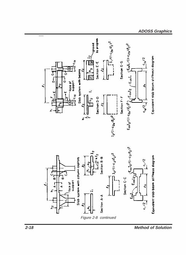
Figure 2-8 continued
2-18 Method of Solution
ADOSS Graphics

Figure 2-9 The equivalent column
The stiffness, Kt of the torsional member is given by the following expression:22
Eq. 2-13
where
Ecs = modulus of elasticity for slab concrete.
C = cross-sectional constant defining torsional properties; see
9EcsCKt = ∑
l 2
c2l (1- )23
Method of Solution 2-19
ADOSS Graphics
22 ACI 318-95, Eq. 13-6; CSA-A23.3-94, Eq. 13.13

Eq. 2-14. It is a conservatively low approximation of thetorsional rigidity of rectangular sections when assumingelastic behavior. For the CSA Standard l2 is taken as thesmaller of l2 or l1.
c2 = size of rectangular column or capital measured transverse tothe direction in which moments are being determined.
l2 = For ACI 318 length of span transverse to l1, measured oneach side of the column. For CSA A23.3 l2 is taken as thesmaller of l2 or l1.
The constant C is evaluated for the cross section by dividing it into separaterectangular parts and by carrying out the following summation:23
Eq. 2-14
where
x = short overall dimension of the rectangular part of a crosssection.
y = long overall dimension of the rectangular part of a crosssection.
As a result of Eq. 2-13, walls24 running the full width of a slab (c2 = l2) cannot bemodeled by the Equivalent Frame Method.
When beams frame into the column in the direction of analysis, the value of Kt ascomputed in Eq. 2-13 is multiplied by the ratio of the moment of inertia of the slabwith the beam (Isb) to the moment of inertia of the slab without the beam (Is), asshown:
Eq. 2-15Kta = Kt
Isb
Is
C = ∑ (1-0.63 )xy
x3y3
2-20 Method of Solution
ADOSS Graphics
23 CSA-A23.3-94, Eq. 13-14
24 Instead walls can be modeled as long supports less than the full design width of the slab. To obtain a uniform distribution of the end moment along the column and middle strips, the width of the wall must be greater than 75% of the design strip.

Figure 2-10 Sections for calculating the stiffness (kc) of the column below the designfloor (lc-input, lc*-computed)
Method of Solution 2-21
ADOSS Graphics

Figure 2-11 Section of the attached torsional members
2-22 Method of Solution
ADOSS Graphics

With reference to Figure 2-9, Is is computed from part A, whereas Isb is computedfrom both parts A and B.
Knowing the column stiffness, Kc, and the stiffness of the attached torsionalmember, Kt, the stiffness of the equivalent column, Kec, is computed from theequation:
Eq. 2-16
Loading
All applied loads are input as unfactored loads. There are no limitations imposedon the ratio of dead to live loads in the Equivalent Frame Method. Results of gravityload and lateral load analyses may be combined, however, the effects of cracking andreinforcement on stiffness must be accounted for in the lateral load analysis.
Self-Weight
The self-weight of the floor system is computed internally by ADOSS. The weightsof the slabs, drops, and longitudinal and transverse beams are considered in the selfweight computations. Only the concrete weight is considered, the reinforcementweight is ignored. The weight of longitudinal beams is ignored starting at thecolumn centerline, for a length equal to one-half c1, the column dimension in thedirection of analysis. This will produce slightly less self-weight than actuallypresent for beams wider than c2, the column’s transverse dimension.
Superimposed Loading
All superimposed vertical loading is considered to act over the entire transversewidth of the slab. Vertical loads acting over less than 1/20 of the span length in thedirection of analysis will be averaged over 1/20 the span length by ADOSS.Concentrated moments are converted into vertical loads producing a couple whichacts over 1/20 the span center-to-center length in the direction of analysis and overthe entire transverse width of the slab. It may be convenient to consider surfaceloading on continuous-beam systems as partial uniform loads. The surface loadingon T-beams acts over the entire input slab width, even if it is greater than the code
Kec =Kct + Kcb
Kct + Kcb
Kta + Kta1+
Method of Solution 2-23
ADOSS Graphics

allowed T-beam flange width. For slab systems with beams, loads supported directlyby the beam (such as the weight of the beam stem or a wall supported directly bythe beams) are also assumed to be distributed over the entire transverse width of thestrip. An additional analysis may be required, with the beam section designed tocarry these loads in addition to the portion of the slab moments assigned to thebeam.
Lateral Loading
For lateral loads, each frame should be analyzed as a unit for the entire height of thebuilding (Figure 2-12). Computer programs, such as PCA-FRAME, are availablefor performing such analyses. It should be realized that, for lateral load analysis,slab-beam elements may have a reduced stiffness due to cracking as well as otherassumptions made for the effective slab width used for the lateral analysis. Themoments obtained from such an analysis may then be input into the analytical modelto determine the appropriate design moments under combined vertical and lateralloads.
An alternate but approximate means of computing the effect of lateral loadsincorporated in this program is the use of a modified ”portal method” to determinethe centerline moments. This method however, is not recommended since it usesuncracked stiffness for slab-beam elements to resist lateral loads. This modifiedportal method is based on the following assumptions:
Figure 2-12 Analytical model for lateral loads
2-24 Method of Solution
ADOSS Graphics

• shear carried by the column is proportional to its flexural stiffness.
• inflection points exist at midheight of columns.
According to the procedure used in ADOSS, the lateral load is divided in proportionto the relative stiffnesses of each column. Moments due to each force are found forcolumns above and below. Note that for positive lateral loads (acting from left toright) these moments have a positive sign and are balanced at each joint by momentsacting on the slab strip. These balancing moments are found on the basis of thestiffness of the slab strips on both sides of the joint. Note that for positive lateralloads (acting from left to right) these moments have a negative sign. Figure 2-13shows the resulting moments from such an analysis. See Figure 5-1 for the signconvention adopted by ADOSS.
By default, ADOSS distributes the effect of lateral load moment, the differencebetween the total load moments, vertical plus lateral, and the vertical only momentenvelopes, to the column strip and middle strip according to the code distributionfactors computed for vertical loads (see Tables 2.4 through 2.6 later in this chapter).However, you may assign a greater percentage of this difference directly to thecolumn strip. The remainder will be distributed to the middle strip and the momentwithin the column strip will be distributed between the beam and slab according tothe code, if applicable.
Figure0e 2-13 Approximate lateral load analysis
Method of Solution 2-25
ADOSS Graphics

Loading Patterns
The analysis of floor systems requires the consideration of several loadingcombinations. Fir example, the two adjacent spans loaded may produce themaximum shear stress around a column, while the alternate spans loaded mayproduce the maximum flexural moments. Furthermore, since the Code25 allows theuse of 75% live load for pattern loading, an additional loading pattern with fullunreduced live load on all spans may be considered.
For vertical loads, the program selects the design requirements for flexure and shearbased on the following loading patterns (Figure 2-14):
Loading Pattern No. l: Two adjacent spans loaded with 75% live load.
Loading Pattern No. 2: Alternate (odd) spans loaded with 75% live load.
Loading Pattern No. 3: Alternate (even) spans loaded with 75% live load.
Loading Pattern No. 4: All spans loaded with 100% live load.
When moments due to lateral loads are entered as input, or when concentratedlateral loads are specified, the following additional loading patterns are considered:
Loading Pattern No. 5: All spans loaded with dead load and the effect ofpositive lateral loads.26
Loading Pattern No. 6: All spans loaded with dead load and the effect ofnegative lateral loads.
Loading Pattern No. 7: All spans loaded with dead and live load and theeffect of positive lateral loads.
Loading Pattern No. 8: All spans loaded with dead and live load and theeffect of negative lateral loads.
2-26 Method of Solution
ADOSS Graphics
25 ACI 318-95, 13.7.6.3; CSA-A23.3-94, 13.9.4
26 A positive lateral load is defined as a horizontal force acting from left to right on theequivalent frame at the left end of the frame. A negative lateral load is defined as ahorizontal force acting from right to left on the equivalent frame at the left end of theframe (see Figure 2-13).

Figure 2-14 Basic pattern live loads
Method of Solution 2-27
ADOSS Graphics

For the ACI 318 Code, the possible combinations of the Dead (D), Live (L), andWind (W) loads considered by the program are:
U1 = 1.4D + 1.7L Eq. 2-17
U2 = 0.75(1.4D + 1.7L +1.7W) Eq. 2-18
U3 = 0.75(1.4D + 1.7L – 1.7W) Eq. 2-19
U4 = 0.9D + 1.3W Eq. 2-20
U5 = 0.9D – 1.3W Eq. 2-21
The Eqs. 2-16 through 2-21 show the default values built into the program.
For the CSA-A23.3 Code, the possible combinations of the Dead (D), Live (L), andWind (W) loads considered by the program are:
U1 = 1.25D + 1.5L Eq. 2-22
U2 = 1.25D + .7(1.5L + 1.5W) Eq. 2-23
U3 = 1.25D + .7(1.5L – 1.5W) Eq. 2-24
U4 = .85D + 1.5W Eq. 2-25
U5 = .85D – 1.5W Eq. 2-26
The Eqs. 2-22 through 2-26 show the default values built into the program.
2-28 Method of Solution
ADOSS Graphics
27 Article 4.1.3.2 of the National Building Code of Canada (NBCC), requires that windand seismic forces be multiplied by load factors of 1.5 and 1.0, respectively. ADOSSmakes no such distinction when dealing with these loads. Unless modified by the user,ADOSS uses the default live load factor of 1.5 for all designs involving the CSA A23.3Standard. Where these designs include the consideration of seismic loads, a modifiedseismic load factor of 1.0 should be input by the user.
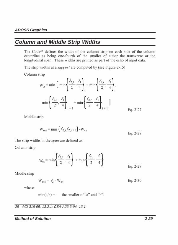
Column and Middle Strip Widths
The Code28 defines the width of the column strip on each side of the columncenterline as being one-fourth of the smaller of either the transverse or thelongitudinal span. These widths are printed as part of the echo of input data.
The strip widths at a support are computed by (see Figure 2-15)
Column strip
Eq. 2-27
Middle strip
Eq. 2-28
The strip widths in the span are defined as:
Column strip
Eq. 2-29
Middle strip
Wms = l2 - Wcs Eq. 2-30
where
min(a,b) = the smaller of “a” and “b”.
{ } { }W = min , + min ,l 2,1
cs 2
l 1
4
l 2,r
2
l 1
4
Wms = min {l 2,i,l 2,i + 1}-Wcs
{ } { }W = min [ min , + min , ,l 2,1
cs 2
l 1
4
l 2,r
2
l 1
4i i
{ } { }min , + min ] l 2,1
2
l 1
4
l 2,r
2
l 1
4i + 1 i + 1
Method of Solution 2-29
ADOSS Graphics
28 ACI 318-95, 13.2.1; CSA-A23.3-94, 13.1

Figure 2-15 Strips widths at support
l1 = span length in the direction of analysis.
l2 = the total input transverse strip width.
l2,1,l2,r = the input transverse strip widths on the left and right ofcolumn dimension, c2, respectively.
2-30 Method of Solution
ADOSS Graphics

Figure 2-16 Strips widths in span
i, i+1 = span left and right of column dimension c1, respectively.
If a beam exists
Wcs = Wcs – Wb Eq. 2-31
If the beam width is greater than the column strip width, Wcs, then
Wms = Wms –(Wb – Wcs) Eq. 2-32
Wcs = 0 Eq. 2-33
where
Wb = beam width.
For exterior frames, the edge width should be specified to the edge of the slab fromthe column centerline.
Method of Solution 2-31
ADOSS Graphics

Design Moments
ADOSS considers negative moments for design purposes as those producingtension at the top of the slab. The negative design moment is taken at a sectionlocated at the face of the column, or column capital, but in no case is it consideredat a location greater than 0.175 of the longitudinal span length, l1, away from thecenter of the column.29 This absolute value is a limit on long narrow supports, inorder to prevent undue reduction in the design moment. For slab systems withtransverse beams, the face of a beam is not considered as the face of support. Forend columns with capitals, the moments are taken at the midpoint of the capitalextension.30 The column and middle strip moments correspond to the momentsassigned to the slab element only.
For ACI designs the column strips are proportioned to resist the portions in percentof interior negative factored moments according to Table 2.4.31
Table 2.4 – Column Strip Percent of Interior Negative FactoredMoments at Supports
The column strips are proportioned to resist the portions in percent of exteriornegative factored moments according to Table 2.5.32
2-32 Method of Solution
ADOSS Graphics
l/2l/1 0.5 1.0 2.0
(a1l/2l/1) = 0 75 75 75
(a1l/2l/1) ≥ 1.0 90 75 45
29 ACI 318-95, 13.7.7.1; CSA A23.3-94; 13.9.5.1
30 ACI 318-95, 13.7.7.2; CSA A23.3-94; 13.9.5.2
31 ACI 318-95, 13.6.4.1; CSA3-A23.3-M94, 13.12.2
32 ACI 318-95, 13.6.4.2

Table 2.5 – Column Strip Percent of Exterior Factored Momentsat Support
The values a1 in Tables 2.4 and 2.5 and bt in Table 2.5 are defined as:
a1 = ratio of flexural stiffness of the beam section to flexuralstiffness of a width of slab bounded by centerlines ofadjacent panels (if any) on each side of the beam in thedirection of analysis. For flat plates, flat slabs, and wafflea1l2l1 = 0.
bt = ratio of torsional stiffness of an edge beam section toflexural stiffness of a width of slab equal to the span lengthof the beam, center-to-center of supports;33 see Eq. 2-34.When no transverse beams are present, bt = 0.
Eq. 2-34
where
Ecb = modulus of elasticity of beam concrete.
Ecb = modulus of elasticity of slab concrete.
C = cross-sectional constant to define torsional properties; seeEq. 2-14.
Is = moment of inertia of the gross section of the slab about itscentroidal axis.
EcbC2EcsIs
ßt =
Method of Solution 2-33
ADOSS Graphics
l/2l/1 0.5 1.0 2.0
bt = 0 100 100 100(a1l/2l/1) = 0
bt ≥ 2.5 75 75 75
bt = 0 100 100 100(a1l/2l/1) ≥ 1.0
bt ≥ 2.5 90 75 45
33 ACI 318-95, 13.0; CSA3-A23.3-94, 13.0

Linear interpolation is performed between values. When a column width, c2, isequal to or greater than 75 percent of the strip width, l2 the negative moment isuniformly distributed across l2.34
When designing by the CSA A23.3 Standard, a portion of the total positive orinterior negative moment equivalent to:
Eq. 2-34a
is resisted by the beam.
For exterior supports the beam is proportioned to resist 100% of the negative moment.
That portion of the moment not resisted by the beam is resisted by the slab. Thereinforcement required to resist this moment is distributed evenly across the slab.
When lateral loads are present, ADOSS, by default, distributes the effects of lateralloads according to Tables 2.4 and 2.5. You may optionally distribute a greaterpercentage of the difference between the total load moment and vertical only loadmoment directly to the column strip. In no case, however, will ADOSS distributeless lateral load moment to the column strip than that required by Tables 2.4 and 2.5,for ACI, or equation 2-34a for CSA.
The middle strips are proportioned to resist the portion of the total factoredmoments that is not resisted by the column strips.
For ACI designs the longitudinal beams are proportioned to resist 85 percent of thecolumn strip moments if a1l2l1 is equal to or greater than 1.0. For values of a1l2l1between 0 and 1.0, the beam is designed to resist a proportionate percentage of thecolumn strip moment between 0 and 85.35
For design purposes, ADOSS computes the amount of reinforcement for themoments on the left and right sides of the support. The negative design moment isthus the moment which requires the most area of reinforcement to be resisted. Thelocation, left or right of the support, of the maximum moment may vary whensystems differ on each side of the support (for example, a system with beams on oneside only). ADOSS considers positive moments for design purposes as thoseproducing tension at the bottom of the slab. The column strips are proportioned to
[1 + (l2/l1)2]
α1
2-34 Method of Solution
ADOSS Graphics
34 ACI 318-95, 13.6.5
35 ACI 318-95, 13.6.5
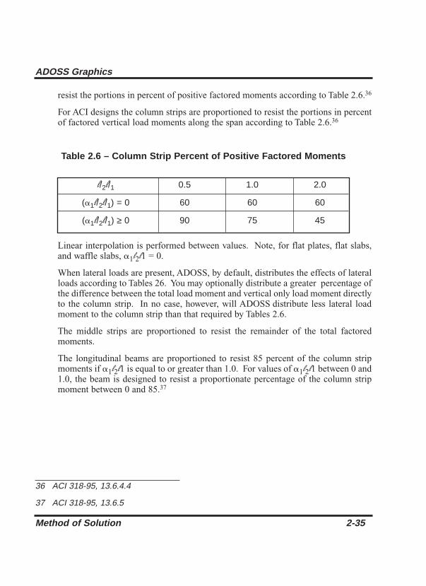
resist the portions in percent of positive factored moments according to Table 2.6.36
For ACI designs the column strips are proportioned to resist the portions in percentof factored vertical load moments along the span according to Table 2.6.36
Table 2.6 – Column Strip Percent of Positive Factored Moments
Linear interpolation is performed between values. Note, for flat plates, flat slabs,and waffle slabs, a1l2l1 = 0.
When lateral loads are present, ADOSS, by default, distributes the effects of lateralloads according to Tables 26. You may optionally distribute a greater percentage ofthe difference between the total load moment and vertical only load moment directlyto the column strip. In no case, however, will ADOSS distribute less lateral loadmoment to the column strip than that required by Tables 2.6.
The middle strips are proportioned to resist the remainder of the total factoredmoments.
The longitudinal beams are proportioned to resist 85 percent of the column stripmoments if a1l2l1 is equal to or greater than 1.0. For values of a1l2l1 between 0 and1.0, the beam is designed to resist a proportionate percentage of the column stripmoment between 0 and 85.37
Method of Solution 2-35
ADOSS Graphics
l/2l/1 0.5 1.0 2.0
(a1l/2l/1) = 0 60 60 60
(a1l/2l/1) ≥ 0 90 75 45
36 ACI 318-95, 13.6.4.4
37 ACI 318-95, 13.6.5

Shear Analysis of Slabs
Three types of shear can occur on slab systems: wide beam shear, punching shear,and moment transfer shear. Wide beam shear or one-way shear on two-way systemsmust be checked manually. This section discusses punching shear includingmoment transfer shear. It is assumed that both types of shear act on the same criticalsection. The critical section for shear is defined in the Code.38
Figure 2-17 shows the general shear area used by ADOSS. Note that the shaded arearepresents the general case and is modified for special considerations as explainedbelow.
2-36 Method of Solution
ADOSS Graphics
38 ACI 318-95, 11.12.1.2; CSA-A23.3-94, 13.4.3
Figure 2-17 Critical section for shear at column

Shallow beams are considered in the unbalanced moment transfer as indicated in Figure2-17. Ordinarily, transverse beams transfer unbalanced moment to the column throughtorsion along the beam and not through shear between the slab and column. However,the Code leaves the transfer method to the engineer’s judgment concerning the point atwhich punching shear is no longer applicable and beam shear becomes the dominateelement in shear transfer to the column. In the default mode of ADOSS, the programmakes no such distinction and computes unbalanced moment transfer stress withoutregard to any beams framing into the column. It is possible, however, to have ADOSSdistribute the shear and torsion among the framing beams. Although the depth of thebeam is considered in the critical section surfaces, the distances to the critical sectionare not increased at the intersection with any beams. This approach is conservative.ADOSS does not compute torsional stresses or one-way beam shear stresses in the slab.If in the engineer’s judgment these may control, they must be computed manually.
For a circular column or column capital, a square shape with an equivalent area isassumed as shown in Figure 2-18. Critical section area for punching, Ac, is thenmultiplied by p(D + d)/(2D =p + 4d) to account for the difference between circularand square critical sections, where D is the diameter of a column or a column capitaland “d” is the effective depth of the slab.
Figure 2-18 Critical section area for circular column
Method of Solution 2-37
ADOSS Graphics

Critical Section for Interior Supports of Interior Frames
The critical section (Figure 2-19) consists of four vertical surfaces through the slab,located at distances of d/2 beyond the support faces.
Figure 2-19 Interior supports of interior frames
For a critical section to be “closed,” the concrete slab around a column must extendto a distance greater than or equal to ten times the slab depth, 10h, beyond thecolumn face. Otherwise the section is considered “open.” The critical section forinterior supports of interior frames is always “closed”. A “closed” section will haveall its faces defined in Figure 2-15, resisting shear as indicated by Eq. 2-35.
Eq. 2-35
If beams frame39 into the column, then the critical section includes the dimensionsof the beams (B1 through B8 in Figure 2-15).
8Ac = ∑ Ai
i = 1
2-38 Method of Solution
ADOSS Graphics
39 A beam is considered as framing into the column if the beam is within a face of the column.
Critical Section for Exterior Supports of Interior Frames
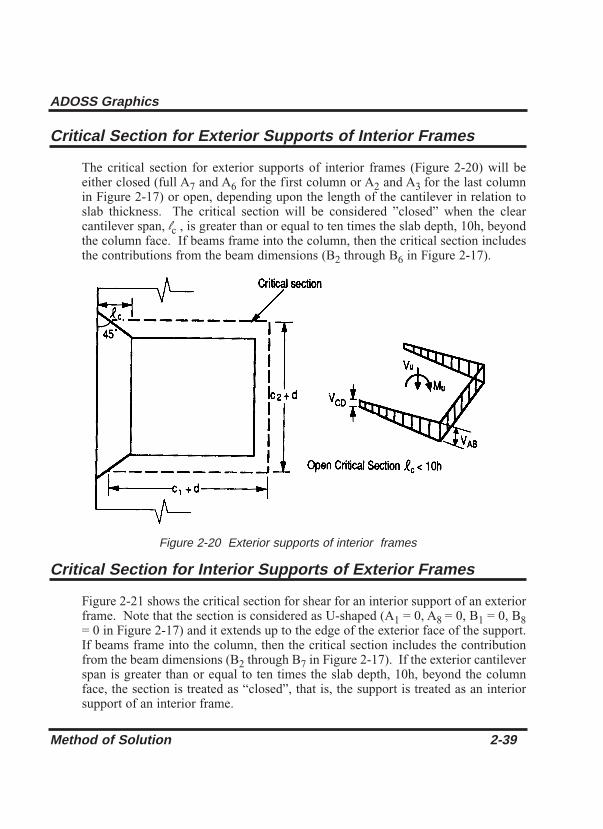
The critical section for exterior supports of interior frames (Figure 2-20) will beeither closed (full A7 and A6 for the first column or A2 and A3 for the last columnin Figure 2-17) or open, depending upon the length of the cantilever in relation toslab thickness. The critical section will be considered ”closed” when the clearcantilever span, lc , is greater than or equal to ten times the slab depth, 10h, beyondthe column face. If beams frame into the column, then the critical section includesthe contributions from the beam dimensions (B2 through B6 in Figure 2-17).
Figure 2-20 Exterior supports of interior frames
Critical Section for Interior Supports of Exterior Frames
Figure 2-21 shows the critical section for shear for an interior support of an exteriorframe. Note that the section is considered as U-shaped (A1 = 0, A8 = 0, B1 = 0, B8= 0 in Figure 2-17) and it extends up to the edge of the exterior face of the support.If beams frame into the column, then the critical section includes the contributionfrom the beam dimensions (B2 through B7 in Figure 2-17). If the exterior cantileverspan is greater than or equal to ten times the slab depth, 10h, beyond the columnface, the section is treated as “closed”, that is, the support is treated as an interiorsupport of an interior frame.
Method of Solution 2-39
ADOSS Graphics

Figure 2-21 Interior supports of exterior frames
Critical Section for Exterior Supports of Exterior Frames
The critical section for an exterior support of an exterior frame (Figure 2-22) willtypically be L-shaped (A1 =0, A6 =0, A7 =0, A8 =0, B1 = 0, B6 =0, B7 = 0 and B8 =0 in Figure 2-17).
If lc, the clear cantilever span, is greater than or equal to ten times the slab depth,10h, beyond the column face, then the section is treated as a U-shaped interiorsupport. If, in addition, the exterior cantilever span is greater than or equal to tentimes the slab depth beyond the column face, 10h, the section is treated as closed.If beams frame into the column, then the critical section includes the contributionsfrom the beam dimensions.
2-40 Method of Solution
ADOSS Graphics

Computation of Allowable Shear Stress at Critical Section
Two-way shear strength of slabs is affected by concrete strength, relationshipbetween size of loaded area and slab thickness, loaded area aspect ratio, perimeterarea aspect ratio (only for ACI 318-89 code option), and shear-to-moment ratio atslab-column connections.
For the ACI 318-95 and CSA A23.3-94 Code, these variables are taken into accountin the allowable shear stress Eqs. 2-36 through 2-39. The allowable shear stress usedby ADOSS is computed at distances of d/2 around the columns and drops (ifapplicable) and taken as the smallest of the 3 quantities:40
Eq. 2-36
Eq. 2-37
Eq. 2-38
where
bc = the ratio of the long to the short side of the column.
as = a constant dependent of the column location, (40 for aninterior 4-sided effective critical area, 30 for an exterior3-sided critical area, 20 for a corner 2-sided effectivecritical area.)
d = distance from the slab bottom to centroid of the slabreinforcement at support.
bo = the perimeter of the critical section.
vc = 4 fc
αsdvc = (2 + )bofc
ßcvc = (2 + ) fc
4
Method of Solution 2-41
ADOSS Graphics
40 ACI 318-95, 11.12.2.1; CSA-A23.3-94, 13.4.4

The allowable shear stress around drops is computed as:
ACI vc = 2 Eq. 2-39
CSA vc = 0.2wc
For the ACI 318 Code, if fct is specified or for concrete types other than normalweight, fct will be substituted for in Eqs. 2-36 through 2-39.41 For waffle slabsystems with valid ribs defined earlier in this chapter, the allowable shear stress isincreased by 10% for ACI designs.42
For CSA designs an additional 1-way shear check is made at end supports ofexterior frames in accordance with CSA A23.3-94 Clause 12.4.6.2
Computation of Factored Shear Force at Critical Section
The factored shear force on the critical section, Vu, by default is computed as thereaction at the centroid of the critical section (e.g., column centerline for interiorcolumns) minus the self-weight and any superimposed surface dead and live loadacting within the critical section. Any partial loads, (uniform, trapezoidal,concentrated), that act within the critical section are not excluded. If the section isconsidered ”open”, two 45 degree lines are drawn from the column corners to thenearest slab edge (lines AF and DE in Figure 2-21) and the self-weight andsuperimposed surface dead and live loads acting on the area ADEF are also omittedfrom Vu (Reference 32).
If beams frame into the column and proportioned moments and shears are requested,ADOSS computes the optional factored shear force, Vu, assuming that the load isdistributed to the supporting beams. The factored shear force in the beams with ana1l2l1 greater than 1 will be computed from the loads on their tributary areas. Theseareas are bounded by two 45 degree lines, originating from the centers of thecolumns at the two ends of the beam span, that extend to the edge of the design stripor to the center of the transverse span (see Figures 2-22 through 2-23). The shear inthe beams will be reduced by (1 - a1l2l1) for beams with a1l2l1 less than 1.
fc
fc
fc
2-42 Method of Solution
ADOSS Graphics
41 ACI 318-95, 11.2.1.1
42 ACI 318-95, 8.11.8

Figure 2-24 Tributary area for shear on longitudinal beams
Computation of Unbalanced Moment at Critical Section
The factored unbalanced moment used for shear transfer, Munbal, by default iscomputed as the sum of the joint moments to the left and right, taken to thecentroidal axis of the critical section.
Method of Solution 2-43
ADOSS Graphics

Figure 2-25 Tributary area for shear on transverse beams
If beams frame into the column and proportioned moments and shears are requested,ADOSS computes the factored unbalanced moment, assuming that the beams resista portion of the moment. The beams in the direction of analysis are assumed toattract the percentage of unbalanced moment based on its a1l2l1, value as defined inthe design moments. The transverse beams are assumed to attract the remainingunbalanced moment when the b1 value, is greater than or equal to 2.5.
The unbalanced moment applied to the transverse beams is reduced by b1/2.5 forbeams with b1 less than 2.5 and the remainder of the unbalanced moment isconsidered directly transferred from the slab to the column.
2-44 Method of Solution
ADOSS Graphics

Computation of Shear Stresses at Critical Section
The punching shear stress printed by the program is based on the following:43
Eq. 2-40
where
Vu = factored shear force on the critical section described above.
Ac = area of concrete, including beams if any, resisting sheartransfer.
w = capacity reduction factor as per the Code = .85.
Under conditions of combined shear, Vu, and an unbalanced moment, Munbal,gvMunbal is assumed to be transferred by eccentricity of shear about the centroidalaxis of the critical section. The shear stress printed by the program (Reference 2-33)for this condition corresponds to:44
Eq. 2-41
where
Munbal= factored unbalanced moment transferred directly from slabto column, as described above.
gv = is the fraction of unbalanced moment consideredtransferred by eccentricity of shear about the centroid of theassumed critical section.45
gv = (1 – gf) Eq. 2-42
vAB = +VuwAc
gvMunbal cABwJc
vu = VuwAc
Method of Solution 2-45
ADOSS Graphics
43 ACI 318-95, 11.12.6.2; CSA-A23.3-94, 13.4.5
44 ACI 318-95, 11.12.6.1; CSA-A23.3-94, 13.4.5.5
45 ACI 318-95, Eq. 11-42; CSA-A23.3-94, Eq, 13-8

where
Jc = property of the assumed critical section analogous to polarmoment inertia.
b1 = width of critical section in the direction of analysis.
b2 = width of critical section in the transverse direction.
Direct shear and moment transfer cause stresses in opposite direction on one face ofthe critical section. ADOSS does not check for the shear stress on this face. If thestress due to direct shear is less than 20% of the allowable shear stress, and if theunbalanced moment transferred by shear is greater than 75% of that required formoment transfer by flexure only, the engineer should manually check46 the shearstress (vCD) on this other face of the critical section.
Local effects of concentrated loads are not computed by ADOSS and must becalculated manually.
Shear Analysis of Longitudinal Beams
When longitudinal beams are present in a span, ADOSS will compute the shearreinforcement requirements for the beams. When the floor is a continuous beamsystem or when proportioning of the moments and shears is not selected for thebeam-supported slab system, ADOSS computes Vu from the load acting over theentire width of the design strip. The program makes no distinction between shallowbeams (a1l2l1 less than 1) and deeper beams (a1l2l1 greater than 1).
When proportioning of the moments and shears is selected for the beam supportedslab system, the beams are proportioned to resist shear caused by loads on tributaryareas. These areas are bounded by two 45 degree lines, originating from the centerof the column at one end of the beam span, that extend to the edges of the designstrip or meet with 45 degree lines drawn from the center of the column at the other
gf = 1
1 + (2/3) b1/b2
2-46 Method of Solution
ADOSS Graphics
46 Based on extensive investigation by N. Hawkins at the University of Washington. For detailed information, see ACI Special Publication SP-42.

end of the beam, see Figure 2-22. The shear applied to the beams will be reducedby 1 - a1l2l1 for beams with a1l2l1 less than 1. Proportioning of moments and shearshas no effect on continuous beam systems.
The “Beam Shear Requirements” table provides Av/s values, the required area oftwo legs of a stirrup, divided by the stirrup spacing. The values are given at adistance “d”, the effective beam depth, away from the column face at both the leftand the right ends of the beam. Values are also given at distances of .175, .375, .625,and .825 times the center-to-center span length, l1 away from the left support.
For ACI 318 Code:
In beams, the shear strength provided by concrete, Vc, is computed by:47
Eq. 2-43
In CSA design, for beams without minimum stirrup reinforcement and greater than300mm deep, vc is calculated from the following equation:
When Vu > wVc/2, the beam must be provided with at least a minimum shearreinforcement of:48
Eq. 2-44=
Av
s50bw
fyv
Vc = ( ) lwc bwd ² 0.10lwc bwdfc fc260
1000 + d
fcVc = 2 bwd
Method of Solution 2-47
ADOSS Graphics
47 ACI 318-95, 11.3.1.1; CSA-A23.3-94, 11.3.5.1
48 ACI 318-95, 11.5.5.2; CSA-A23.3-94, 11.2.8.4

where
Av = area of two legs of a stirrup,
s = stirrup spacing,
bw = longitudinal beam width, and
fyv = yield strength of the shear reinforcement.
When Vu > wVc, shear reinforcement must be provided so that:
Eq. 2-45
where
Vu = factored shear force at the section being considered, and
d = effective depth of the beam at the same location.
When Vu exceeds w5Vc, the beam section dimensions must be increased or a higherconcrete strength must be provided.50
When segmental moments and shears are requested, ADOSS will print stirrupspacing for four bar sizes. When Vu ≤ w10 bwd, the spacing is computed as:
Eq. 2-46
where
Asb = total bar area of the two legged stirrup.
The maximum stirrup spacing must not exceed d/2 nor 24 in. when Vu ≤ w6 bwd. When Vu > w6 bwd, the maximum stirrup spacing must befcfc
Avs = Asb
s
1
fc
=Av
sVu–wVc
wfyvd
2-48 Method of Solution
ADOSS Graphics
49 ACI 318-95, 11.5.6.1; CSA-A23.3-94, 11.3.7
50 ACI 318-95, 11.5.6.8; CSA-A23.3-94, 11.3.4
51 ACI 318-95, 11.5.4; CSA-A23.3-94, 11.2.11
reduced by half, to d/4 or 12 in.51 When Vu > w10 bwd, the beam section dimensions must be increased or a higher concrete strength must be provided.
fc

Shear and Torsion Analysis of Transverse Beams
When transverse beams frame into a column, ADOSS will compute the shear andtorsional requirements for each beam at a distance d, the transverse beam effectivedepth, away from the transverse face of the column. The distance to the topreinforcement from the tension face in the transverse beam is taken as that specifiedfor the top reinforcement in the slabs.
The shear applied to each transverse beam, Vu, is computed from loads on the beamtributary area. These areas are bounded by two 45 degree lines, originating from thecenter of the column, that extend to the edge of the design strip or to the centerlinesof the panels parallel to the long side (Figure 2-25).
The torque applied to each transverse beam is computed from the unbalancedmoment as documented below:
Eq. 2-47
Eq. 2-48
where
Tu,1, Tu,r = transverse beam torques on the front and back faces of thecolumn, respectively.
Kt,1, Kt,r = the torsional stiffness of the transverse beam on the frontand back faces of the column, respectively.
Munbal = the unbalanced moment at the center of the column.
The torque is assumed to be linearly distributed along the transverse beam. Themaximum torque occurs at the joint center, and zero torque occurs at the slab panelcenter, transverse to the design direction (Figure 2-26).
When proportioning of the moments and shears is selected, the shear, Vu, resistedby the beams will be reduced by 1 - a1l2l1 for beams with an a1l2l1 less than 1. The
Tu,r = ( ) Munbal Kt,r
Kt,1 + Kt,r
Tu,1 = ( ) Munbal Kt,1
Kt,1 + Kt,r
Method of Solution 2-49
ADOSS Graphics
52 ACI 318-95, 11.6.1; CSA-A23.3-94, 11.2.9.1

torque applied to the beams will be reduced by bt/2.5 for beams with bt less than2.5, see Eq. 2-34.
When the applied torque is less than w (Acp2/Pcp) no torsional reinforcement is
required and the shear reinforcement for the transverse beam is designed using theprocedure for longitudinal beams.53
The shear reinforcement for the transverse beam is designed using the procedure forlongitudinal beams.54
Figure 2-26 Distribution of torque intransverse beams
If the applied shear, Vu, exceeds wVc/2, but is less than wVc and/or the appliedtorque, Tu, is greater than w (Acp
2/Pcp) minimal shear and torsionalreinforcement must be provided as follows:55
Eq. 2-52
Avs
2Ats
+50Bw
fw≥
fc
fc
2-50 Method of Solution
ADOSS Graphics
53 ACI 318-95, 11.3; CSA-A23.3-94, 11.3
54 ACI 318-95; 11.5; CSA-A23.3-94, 11.3.7
55 ACI 318-95; 11.6.5.2

The total stirrup reinforcement area is computed by:
Eq. 2-53
where
Av = area of two legs of a closed stirrup,
At = area of one leg of a closed stirrup.
When Tu exceeds w (Acp2/Pcp), the required area of one leg of a closed stirrup
divided by its spacing, At/s, is computed by:56
Eq. 2-54
where
cotw = 1
When the applied torque exceeds w (Acp2/Pcp), the cross-sectional; dimensions
shall be such that:57
Eq. 2-55
The required area for longitudinal torsion reinforcement Al is taken as:58
Eq. 2-56
The maximum value for At/s in Eq. 2-56 is taken as the value obtained from Eq. 2-54.
fyvAt
fytsAl = Ph ( )cot2u
( ) ( +8 )( ) fcVubwd
Vcbwd
TuPh1.7Aoh
2 2+ ≤ w
fc
Ats
Tn2Aofycotw
=
fc
Atots
Avs
2Ats
= +
Method of Solution 2-51
ADOSS Graphics
56 ACI 318-95, 11.6.3.6
57 ACI 318-95, 11.6.3.1; CSA A23.3-94, 11.3.9.8
58 ACI 318-95, 11.6.3.7; CSA A23.3-94, 11.3.9.5

Area of Reinforcement
ADOSS only computes reinforcement at the top of the floor system at the supportsand at the bottom of the floor system in the span. If reinforcement is required at thebottom of the floor system at a support or at the top of the floor system in the span,it must be designed manually based on the design moments provided. Thereinforcement at the support is computed from the negative design moment whichrequires the most area of reinforcement to be resisted. The location, left or right ofthe support, of the maximum moment may vary when systems differ on each side ofthe support for example, a system with beams on one side only).
For rectangular sections with no compression reinforcement, the design flexuralstrength of the column strip, middle strip or beam must equal the factored designmoment:
ACI 318-95
Eq. 2-57
The reinforcement can therefore be computed from:
Eq. 2-58
For CSA A23.3-94
The effective depth of the section is taken as the overall section depth minus thedistance from the extreme tension fiber to the tension reinforcement centroid. Thecolumn strip depth may include all or part of the drop panel depth. The drop depthwill not be included in the effective depth of the column strip when the drop does
Mr = fs fy As (d - )fs As fy
2(a1wcfc)b
fy w.85fc b0.85fc b (d – d2 – )As =
2Mu
Asfy
2(0.85fc)bMu = wfyAs(d – )
2-52 Method of Solution
ADOSS Graphics

not extend at least one-sixth the center-to-center span length in all directions, orwhen the drop depth below the slab is less than one-quarter the slab depth. If thedrop does extend at least one-sixth the center-to-center span length and the dropdepth is greater than one-quarter the distance from the edge of the drop panel to theface of the column or column capital, the excess depth will not be included in thecolumn strip effective depth. If the drop width is less than the column strip width,the drop width will be used in the computation of the required reinforcement.
Continuous beam systems may be designed as T-beams and may have both tensileand compressive reinforcement.
In all cases, the steel ratio will be kept below 75 percent rb, where:59
Eq. 2-59
where
rb = 0.85 for ≤ 4 ksi
= = 0.65 for ≥ 8 ksi
= 1.05 – .05 x for 4 ksi < < 8 ksi
If the slab cannot be reinforced, a “cannot design system” message will appear andthe program will terminate prematurely to indicate the need for compressionreinforcement. In such cases, it is recommended that the engineer review the slabthickness to ensure a more satisfactory design. For continuous beam systems,ADOSS will attempt to add compression reinforcement to the section.
The amount of reinforcement provided will not be less than the code prescribedminimum. For the ACI 318 Code, the minimum ratio of reinforcement area, to thegross sectional area of the slab strip, using Grade 60 reinforcement, is taken as.0018. When reinforcement yield strength exceeds 60 ksi, the minimum ratio is setto .0018 x 60/fy. For reinforcement with yield strength less than 60 ksi, theminimum ratio is set to 0.0020. In no case will this ratio be less than .001460. (SeeTable 2.7). The CSA Standard requires a minimum ratio of slab reinforcement areato gross sectional area of the slab strip equal to 0.002 for all grades of reinforcement.
fcfc
fc
fc
fy
fc
87 + fy
87rb = .85b1
Method of Solution 2-53
ADOSS Graphics
59 ACI 318-95, 8.4.3; CSA A23.3-94 10.5.2
60 ACI 318-95, 7.12; CSA A23.3-94, 7.8

For beams and positive moment regions of waffle slabs, minimum reinforcementratio, r,provided will not be less than:61
Eq. 2-60
but not less than 200bwd/fy
Table 2.7 – Minimum Ratios of Reinforcement to Gross Concrete Area
Reinforcement Selection
The ADOSS default minimum spacing of reinforcement is 6 in. (150 mm) in slabsand 1 in. (25 mm) in beams. The 6 in. minimum for slabs was chosen for practicalreasons only. The minimum in no case will be less than the Code prescribed minimafor both slabs and beams of one bar diameter, db, or 1 in.62
For ACI 318 the maximum spacing of reinforcement is kept at two times the slabthickness.63
For CSA A23.3 banded reinforcement is spaced at a maximum of 1.5 hs whiledistributed reinforcement is spread at a maximum of 3 hs.
An iterative process is performed to determine the number of bars and bar size. Theinitial number of bars is determined by dividing the total reinforcement area required,As, by the area of one bar, Asb, of the input minimum bar size. An additional bar is
fy
3 fcAs,min = bwd
2-54 Method of Solution
ADOSS Graphics
fy (ksi As/Ag
< 60 0.0020
≥ 60 0.0018fy
x 60 ≥ 0.0014
61 ACI 318-95, 10.5
62 ACI 318-95, 7.6.1
63 ACI 318-95, 13.4.2

provided if the difference between the required and the provided reinforcement areasis greater than 20% of one bar area or 0.2 in.2. Next, the spacing is determined. Ifthe minimum spacing limitations are violated, the bar size is increased and theiterative process continues until all bars sizes have been checked. If the maximumspacing limitations are not met, the number of bars required to satisfy theselimitations is computed and the iteration process terminates.
For beams, layered reinforcement is provided if sufficient beam width is not available.ADOSS assumes a 1.5 in. cover to a #4 (an SI N-10) stirrup for width calculations.ADOSS also assumes that the longitudinal bar makes contact at the middle of thestirrup bend where the minimum inside diameter of the bend is 4db. Therefore, anadditional width is added to the cover for longitudinal bars less than #14 (an SI N-45)in size (Figure 2-25). This additional width due to the bend, wbend, is equal to:
wbend = 0.293 (1.0 – db/2) Eq. 2-61
where
db = bar diameter of the longitudinal bar.
The clear distance between layers is assumed 1.0 in. Hooks and bends are notincluded in bar length figures.
Figure 2-27 Width due to stirrup bend
Method of Solution 2-55
ADOSS Graphics
64 ACI 318-95, 7.6.5
65 ACI 318-95, 7.2.2

Figure 2-28 Detail of reinforcement in longitudinal beams
Bar-length computations are performed for two-way slabs only. For reinforcementat the top of the slab at the supports, the length for short bars is given by:
Eq. 2-62
and the length for long bars is given by:
Eq. 2-63
llong = greater of {max lip, + greater of {ld, short + lcr {
d12dbln/16
0.5 max (lip)ld short + lcr
lshort = greater of {0.5 max ( lip) + greater of {ld, short + lcr
d12dbln/16
2-56 Method of Solution
ADOSS Graphics

where
max(lip) = maximum distance to the inflection points, where thedistances are the same for both the column and middlestrips,
ld = bar development length,66
d = effective, depth,
db = bar diameter,
ln - clear span length.
These bar lengths are then compared and adjusted if necessary to the minimumrequirements specified by the code.67
If the computed bar lengths overlap, it is recommended that such reinforcement berun continuously. The printed bar lengths do not include hooks or portions of barsbent down into spandrel beams or other bar-bend configurations.
The selection of bar lengths for positive reinforcement for flat plates, flat slabs, andbeam-supported slabs, is based strictly on the minimum values of the Code. Forwaffle slabs, however, the positive reinforcement selection is based on an additionalassumption of two bars per joist. For purposes or output, one bar is treated as a longbar and the other as a short bar.
The computation of tension development lengths in terms of db is given by thegeneral expression:
Eq. 2-64
The development length depends on some of the following factors: concrete cover,minimum transverse reinforcement, special transverse reinforcement, layer locationbar size and bar clear spacing.
lddb
=3
40
fy abgl
fcdb
c + kcr[ ]
Method of Solution 2-57
ADOSS Graphics
66 ACI 318-95, Chapter 12; CSA-A23.3-94, Clause 12.2
67 ACI 318-95; Figure 13.4.8; CSA-A23.3-94, Figure 13.1

Additional Reinforcement at Support
ADOSS computes the fraction of the unbalanced moment, gfMu, that must betransferred by flexure within an effective slab width equal to the column width plusone and one-half the slab or drop panel depth (1.5h) on either side of the columnwhere:68
Eq. 2-65
The amount of reinforcement required to resist this moment is computed. Theamount of reinforcement already provided for negative flexure is then computedfrom the bar schedule (i.e. the number of bars that fall within the effective slab widthmultiplied by the area of each bar). If the reinforcement area provided for flexureis greater than or equal to the reinforcement requirements to resist moment transferby flexure, no additional reinforcement is provided, and the number of additionalbars will be set to 0. If the amount of reinforcement provided for flexure is less thanthat required for moment transfer by flexure, additional reinforcement is required.The additional reinforcement is the difference between that required for unbalancedmoment transfer by flexure and that provided for design bending moment in theslab, and it is selected based on the bar size already provided at the support.
It should be noted that the Code requires either concentration of reinforcement overcolumn beam joint by closer spacing, or additional reinforcement, to resist thetransfer moment within the effective slab width. ADOSS provides additionalreinforcement, and does not concentrate existing reinforcement.
For the ACI Codes, at least two of the column strip bottom bars should becontinuous or spliced at the support with Class A splices or anchored with thesupport.
gf =1
1 + b1/b223
2-58 Method of Solution
ADOSS Graphics
68 ACI 318-95, 13.5.3.2; CSA-A23.3-94, 13.4.5.3

Additional Information in Span
The total static design moment for each span based on average widths and loads onthe span is computed as per the Code. Partial loads are not taken into account.
Deflection Calculation
Calculation of deflections of reinforced concrete two-way slabs is complicated by alarge number of significant parameters such as: the aspect ratio of the panels, thevertical and torsional deflection of supporting beams, the stiffening effect of droppanels and column capitals, cracking, and the time-dependent nature of the materialresponse. Based on studies in References 2-22–2-24, an approximate methodconsistent with the equivalent frame method was developed (2-25) to estimate thecolumn and middle strip deflections.
Under vertical loads, Reference 2-23 indicates that the midspan deflection of anequivalent frame can be considered as the sum of three parts: that of the panelassumed to be fixed at both ends of its span, and those due to the known rotation atthe two support lines. The midspan “reference” deflection of a uniformly loadedequivalent frame with fixed ends is:
Eq. 2-66
where
W = is the uniform load in units of weight per length squared,
Ec = modulus of elasticity of the slab concrete,
Iframe = moment of inertia of the full-panel width.
Calculation of the midspan deflection of the column strip or the middle strip underfixed-end conditions is based on the M/EI ratio of the strip to that of the full-widthpanel:
Eq. 2-67
af,strip = af,refMstrip EcIframe
Mframe EcIstrip
af,ref =Wl 4
384EcIframe
Method of Solution 2-59
ADOSS Graphics

The ratio (Mstrip/Mframe) can be considered as a lateral distribution factor, LDF. Thelateral distribution factor, LDF, at an exterior negative moment region is:
Eq. 2-68
The LDF at an interior negative moment region is:
Eq. 2-69
The LDF at a positive moment region is:
Eq. 2-70
where
a1 = the ratio of flexural stiffness of a beam section to theflexural stiffness of a width of slab bounded laterally bycenterlines of adjacent panels on either side of the beam.
bt = ratio of torsional stiffness of an edge beam section to theflexural stiffness of a width of slab equal to the span lengthof the beam, center-to-center of the supports. (See Eq.2-34)
When a1l2l1 is greater than 1.0, a1l2l1 will be set equal to 1.0.
The column and middle strip LDF’s can be computed by:
Eq. 2-71
Eq. 2-72LDFm = 100 - LDFc
LDFc =LDFpos +
LDFneg,l + LDFneg,r
22
LDFpos = 60 + 30(a1 – )(1.5 – – )l2l1
l2l1
LDFneg,int = 75 – 30(a1 – )(1 – – )l2l1
l2l1
LDFneg,ext = 100 – 10bt + 12bt(a1 – )(1 – – )l2l1
l2l1
2-60 Method of Solution
ADOSS Graphics

where
LDFneg,1, = LDF for the negative moment region at the left and right LDFneg,r end of the span, respectively.
If the ends of the columns at the floors above and below are assumed fixed (as isusual in an equivalent frame analysis), then the rotation of the column is equal to thenet applied unbalanced moment divided by the stiffness of the equivalent column:
Eq. 2-73
The midspan deflection of the panel having an end rotation of Q radians, with thefar end fixed, can be computed as:
Eq. 2-74
The total midspan deflection for the column or middle strip is the sum of the threeparts:
Eq. 2-75
where
= midspan deflection due to rotation of left and right supports,respectively.
The deflections should be used in conjunction with the deflections obtained from ananalysis in the perpendicular direction. For square panels (l1 = l2), the midpaneldeflection is obtained by Eq. 2-736a as shown in Figure 2-29:
Eq. 2-76a
For rectangular panels, (l1 ≠ l2), the midpanel deflection is obtained by Eq. 2-76b:
a = acy + amx = acx + amy
au,l, au,r
astrip = af,strip + au,l + au,r
au =ul
8
u =Munbal
Kec
Method of Solution 2-61
ADOSS Graphics

Eq. 2-76b
For cantilever spans, Eq. 2-66 must be modified to:
Eq. 2-77
where
Pi = load within segment i of the cantilever span,
xi = distance of load Pi from the support,
l = cantilever span.
Eq. 2-78au = ul
af,ref =20∑
i = 1
Pi xi2 (3l – xi)
6EcIframe
a = [(acy + amx) + (amy + acx)]/2
2-62 Method of Solution
ADOSS Graphics
69 ACI 318-95, 9.5.2.3

Figure 2-29 Deflection computation for a square panel
Note that the value of Iframe in Eq. 2-77 is taken as the effective moment of inertiaat the support. Also, this method is applicable to short cantilevers and small loads.Deflections due to large loads and long cantilevers must be computed manually.Local deflections due to concentrated loads are not considered by the program andmust be computed manually.
Method of Solution 2-63
ADOSS Graphics

Deflections of Continuous Beams and One Way Slabs
Continuous beam and one way slab deflections are computed based on simplysupported deflections less the deflection due to the end support rotations. Theeffects of support settlement or shear deformations are not considered. Whensegmental moments and shears are requested, the segmental deflections printed areat 20 equally spaced sections along the span. Concentrated loads occurring at otherlocations will give rise to larger deflections. These must be checked manually.
Cracking
The effect of cracking in slabs, as in beams, is a reduction in the flexural stiffness.The effect of cracking is generally an increase in deflections, although the tensileconcrete between cracks continues to have a stiffening influence. A detailed reviewof several methods of deflection analyses can be found in Reference 2-24. To applythe Code-specified effective moment of inertia to slab systems, a value of Ia,frame isused instead of Ia,frame in Eqs. 2-66, 2-67, and 2-77. The value of Ia,frame is givenby:
Eq. 2-79a
where
Ie+ = effective moment of inertia for the positive moment region.
Ie–,l = effective moment of inertia for the negative moment region
at left support.
Ie–,r = effective moment of inertia for the negative moment region
at right support.
b an empirical constant based on experimental data, whosevalue is less than 1.0.
For continuous beams, the appropriate value of b compatible with experimental datawas found to be 0.7. For flat plates, flat slabs, and waffle slabs, the appropriatevalue of b appears to be 0.5. ADOSS uses a value of 0.5 for flat plates, flat slabs,and waffle slab systems and 0.7 for beam-supported slabs, continuous beams, andone way slabs.
Ia,frame = bIe+ + (1–b) (Ie
-,l + Ie,r-)/2
2-64 Method of Solution
ADOSS Graphics

The value of Ia,frame for cantilever spans is given by:
Eq. 2-79b
where
Ie–,end = effective moment of inertia for the negative moment region
at the cantilever end.
Ie–,sup = effective moment of inertia for the negative moment region
at support.
For continuous beams, the appropriate value of b compatible with experimental datawas found to be 0.15. For flat plates, flat slabs, and waffle slabs, the appropriatevalue of b appears to be 1.0. ADOSS uses a value of 1.0 for flat plates, flat slabs,waffle slabs, and beam-supported slabs, and 0.15 for continuous beams, andone-way slabs.
The value of Ie corresponds to the effective moment of inertia as developed byBramson (2-26) and incorporated into the Code as follows:69
Eq. 2-80
where
Ig = moment of inertia of the gross uncracked concrete sectionfor the full width of the equivalent frame.
Icr = moment of inertia of the cracked transformed concretesection for the full width of the equivalent frame.
Mcr = cracking moment for the full width of the equivalent frame.
Mmax = maximum bending moment for the full width of theequivalent frame at the load stage at which deflection iscomputed.
It should be noted that the use of the full slab width in determining Ie in Eq. 2-77 isintended to average the effects of cracking of the column and middle strips.
Ic = { }3 Ig
+ [1–{ }3]Icr
McrMmax
McrMmax
Ia,frame = bIe-,sup + (1–b) Ie
-,end
Method of Solution 2-65
ADOSS Graphics

Deflection Computations
Instantaneous Deflections. Two values of midspan deflections are computed bythe program for each span. The first corresponds to dead load on all spans, while thesecond corresponds to dead load plus live load on all spans. Note that the live loaddeflection is always computed as total load deflection minus the dead loaddefection. This is consistent with the Ieff method outlined in the Code
Long Time Deflections. The total midpanel deflection (including long-timeeffects) consists of the following:
Eq. 2-81
where
a = elastic deflection,
acreep = additional deflection due to creep,
ash = additional deflection due to shrinkage, and
atotal = total deflection.
Data reported in the literature, although limited in quantity, indicate that theadditional deflection due to creep and shrinkage, acreep + ash, may be as much as twoto eight times the elastic deflection, a (References 2-27–2-30). Such a factor timesthe dead load deflection may be used for an estimate of required slab camber.
For a crude approximation to a complex problem, additional long-time deflectionsmay be computed as three times the elastic deflections. For a more detailed methodof analysis of long-time deflection the user is referred to a study by Rangan.(Reference 2-30.)
atotal = a + acreep + ash
2-66 Method of Solution
ADOSS Graphics
Material Quantities
The program computes concrete, reinforcing steel, and formwork quantities. Thequantity of concrete is based on an average of the slab, drop, and beam sizes. Thetotal quantity of reinforcing steel computed by the program corresponds to theactual bar sizes and lengths required by design. No allowance is made for bar hooks,anchorage embedment, and so forth. It should be noted that the quantity ofreinforcement printed by the program pertains to bending in one direction only. Inpractice, the total amount of reinforcement for the structure should also include thequantities obtained for the appropriate perpendicular equivalent frames.
Method of Solution 2-67
ADOSS Graphics
Chapter 3
Menu Descriptions
ADOSS Graphics Menu Descriptions
ADOSS Graphics uses pull down menus to access commands that allow input of thefloor geometry, manipulate ways to view the system, and ultimately design thesystem and review the results. This section gives a summary of each command in allthe pull down menus. Use this chapter to learn what functions ADOSS commandsperform.
The File Menu
The File menu is used for saving or retrieving data, printing, and exiting. The Filemenu contains the following commands: New, Open, Save, Save As, Export, Revert,Print Screen, Print Results, and Exit.
NewThe New command clears any data input, returns to the default values, and beginsthe Auto Input process (see the “Auto Input” command from the Input menu later inthis chapter). Thus, you are able to create a new data file. However, before you canbegin a new data file, ADOSS will ask whether you want to save the current data.Answering yes will save the old data and begin a new data file. Answering no willdiscard any changes to the data and begin a new data file. Answering cancel willreturn you to ADOSS so that you can continue to work with the current data.
See ”Creating a New Data File” of Chapter 4 for more information on using theNew command.
OpenThe Open command allows you to load an existing ADOSS data file. The dialogbox that appears shows you a listing of all the files with the extension contained inthe default data directory or in the current directory (if a default data directory was
Menu Descriptions 3-1

not specified). This box also enables you to change the current drive and directory.If you are currently working on a data file and select the Open command, ADOSSwill ask whether you want to save the current data. Answering Yes will save the olddata and display the Open dialog box. Answering No will discard any changes tothe data and display the Open dialog box. Answering cancel will return you toADOSS so that you can continue to work with the current data.
See ”Opening an Existing Data File” of Chapter 4 for more information on using theOpen command.
SaveThe Save command saves the changes you’ve made to the current data under thatsame filename. The new data overwrites the old data, and you cannot retrieve theold data. It is a good practice to periodically Save while inputting data. If a datafile is untitled, the Save As dialog box will appear.
See ”Saving Your Data” of Chapter 4 for more information on using the Savecommand.
Save AsThe Save As command allows you to name or rename a data file. Use Save As whenyou want to save both the original data and any changes you’ve currently made tothe data. The original data remains under the old filename. If a file of the samename exists, the program will ask if you would like to overwrite the file.
See “Saving Your Data” of Chapter 4 for more information on using the Savecommand.
ExportThe Export command saves the current data file into a file format other than thedefault format. By using the “ADOSS V4.X-V5.2X” conversion utility from theprovided list, the Export command ensures compatibility between ADOSS V6.00and previous versions by converting V6.00 data files to a format that is readable byprevious versions.
See ”Saving Your Data” of Chapter 4 for more information on using the Savecommand.
3-2 Menu Descriptions
ADOSS Graphics

RevertThe Revert command is used to discard current changes to the data and return to theversion of data saved in the original data file. This option will only be enabled ifthe file had been saved prior to editing.
Print ResultsThe Print Results command allows you to send the analysis and design results to theprinter. By selecting options in the Output Options command prior to performingthe design, you can print selected sections of the data instead of the entire analysis.
See “Viewing and Printing the Results” and ”Condensing the Output” of Chapter 4for more information on using the Print Results command.
Print ScreenThe Print Screen command prints the floor system geometry in the plan, elevated,and isometric views, prints the shear and moment diagrams, and prints the deflectedshapes. To obtain a print you must first perform the design of the view, then viewthe shear and moment diagrams or the deflected shapes.
See “Viewing and Printing Shear and Moment Diagrams” and “Viewing andPrinting Deflected Shapes” of Chapter 4 on using the Print Screen command.
ExitThe Exit command ends the ADOSS session and returns you to Windows. If you’vemade any changes to your data and have not saved them, ADOSS will first askwhether you want to save or abandon any changes you’ve made before you exit.
Menu Descriptions 3-3
ADOSS Graphics

The Input Menu
The Input menu allows you to enter and modify data for the floor system.
Auto InputThe Auto Input command is designed to make the inputting process easier. Byselecting Auto Input, a logical sequence of dialog boxes will automatically bedisplayed allowing you to enter data for your floor system. Depending on the floorsystem selected, the program will display only those dialog boxes required to designyour floor system.
See ”Creating a New Data File” of Chapter 4 for more information on using theAuto Input command.
LabelsThe Labels command allows you to enter the project name, span id, engineer, date,and time. Date and time are automatically filled when a new file is created. Thisinformation will be printed with the output and is intended to help you organize yourdata.
See “Including Labels with the Output” of Chapter 4 for more information on usingthe Labels command.
General InformationThe General Information command will allow you to enter the number of spans, units,code, structure type, frame location, lateral loads, loading pattern, and the designoption. You must always choose the General Information command before doing anyfurther inputting since it affects the availability of other commands in this menu.
See “Using the General Information Command” of Chapter 4 for more informationon using the General Information command.
Material PropertiesThe Material Properties command enables you to input material propertyrequirements for concrete and reinforcement. Concrete density, compressivestrength, tensile splitting strength, modulus of rupture, as well as the longitudinaland shear reinforcement yield levels are required.
3-4 Menu Descriptions
ADOSS Graphics

See “Defining the Material Properties” of Chapter 4 for more information on usingthe Material Properties command.
Reinforcement DataThe Reinforcement menu contains commands that allow you to specify the distanceto reinforcement, reinforcement bar sizes, and minimum bar spacing for both slabsand beams. Depending on the type of floor system you have selected, either Slabsor Beams or both of these commands will be available.
See “Defining Reinforcement Parameters” of Chapter 4 for more information onusing the Reinforcement Data menu.
GeometryThe Geometry menu contains commands that allow you to input geometricdimensions for slabs, ribs, longitudinal beams, columns/capitals, drops, andtransverse beams. A cascading menu contains the member types to modify.Depending on the floor system, some menu items will be disabled.
See “Defining the Structure Geometry” of Chapter 4 for more information on usingthe Geometry menu.
LoadsThe Loads menu contains commands that allow you to enter superimposed uniformloads, trapezoidal loads, concentrated axial loads and moments, lateral loads, andallows you to modify the load factors. Depending on the lateral load type, somemenu items will be disabled.
See “Specifying Loads on the Structure” and “Using the General InformationCommand” of Chapter 4 for more information on using the Loads menu.
Column FixityThe Column Fixity command allows you to modify the percentage of the actualcolumn joint stiffness to be used in the analysis to determine the joint moments andshears.
See “Changing the Column Fixity” of Chapter 4 for more information on using theColumn Fixity command.
Menu Descriptions 3-5
ADOSS Graphics

The View Menu
The View menu commands enable you to modify the floor system’s appearance on thescreen to suit your viewing needs. The following is a list of what is available in this menu.
RedrawThe Redraw command will redraw the floor system in full size. If you have alteredyour screen view using the Zoom command, select Redraw to restore the figure’soriginal proportions.
Scale On/OffThe Scale On/Off commands allow you to view your floor system with or without ascale in ft. (m) along the left and top edge of the view window. The left edge of thefloor system and the column centerline is considered the origin.
See “Viewing the Floor System with a Scale” of Chapter 4 for more information onusing the Scale On/Off commands.
ZoomThe Zoom command enables you to zoom in on any portion of your floor system forcloser analysis. By selecting zoom and either using the mouse or keyboard arrowkeys to specify a zooming region, the program will enlarge the portion you select.
See “Zooming in on the System” of Chapter 4 for more information on using theZoom command.
Change Isometric AngleThe Change Isometric Angle command allows you to modify the angle at which thefloor system is displayed in the Isometric View. The default angles are set at -45about the X and 45 about the Z axis.
See “Changing the Isometric View Angle” of Chapter 4 for more information onusing the Change Isometric Angle.
View MembersThe View Members command allows you to view selected members of the floorsystem in the views windows. Clicking the left mouse button on the box next to the
3-6 Menu Descriptions
ADOSS Graphics

items in the dialog box, or tabbing to the member type and pressing the space bar willtoggle the selection. ADOSS will draw any members that contain a check in the box.
See “Viewing Specific Member Types” of Chapter 4 for more information on usingthe View Members command.
View LoadsThe View Loads command allows you to view selected loads of the floor system inthe Partial Loads window. Clicking the left mouse button on the box next to theitems in the dialog box, or tabbing to the type and pressing the space bar will togglethe selection. ADOSS will draw any loads that contain a check in the box.
See “Viewing Specific Load Types” of Chapter 4 for more information on using theView Loads command.
View ResultsThe View Results command will execute PCA View, so you may view the designresults for your floor system on the screen after a design has been performed. ThePCA View window, displaying the results, will overlap the main window of theADOSS program.
See “Viewing and Printing the Results” of Chapter 4 for more information on usingthe View Results command.
View Shears/MomentThe View Shears/Moments command creates a window displaying a shear andmoment diagrams of a particular span and load pattern after a design of the floorsystem has been performed.
See “Viewing and Printing Shear and Moment Diagrams” of Chapter 4 for moreinformation on using the View Shear/Moment command.
View DeflectionsThe View Deflections command creates a window displaying the deflected shape ofa particular span of a continuous beam or one-way slab system after a design of thefloor system has been performed.
See “Viewing and Printing the Deflected Shapes” of Chapter 4 for more informationon using the View Deflections command.
Menu Descriptions 3-7
ADOSS Graphics

The Design Menu
The Design menu contains commands that enable you to perform the analysis anddesign of the floor system or column section.
Condense/Expand Output The Condense/Expand Output command allows you to suppress portions of theoutput. ADOSS will print only those items that have a check in the box. To takeeffect, the design must be performed after the Condense/Expand Output commandis executed.
See “Condensing the Output” of Chapter 4 for more information on using theCondense/Expand Output command.
Design SystemThe Design System command executes the solver portion of ADOSS. If some datais still required when this command is executed, ADOSS will respond with ”Moredata required” and display the dialog box that must be completed.
See “Designing the Floor System” of Chapter 4 for more information on using theDesign System command.
Design ColumnThe Design Column command executes PCACOL if it is found on the computersystem. This option will be grayed if PCACOL is not found after the design of thefloor system is performed. In order for ADOSS to find PCACOL, the directorywhere PCACOL resides must be in the DOS PATH statement. (See your DOSmanual for help on the PATH statement.)
See “Designing the Column” of Chapter 4 for more information on using the DesignColumn command.
3-8 Menu Descriptions
ADOSS Graphics

The Options Menu
The Options menu allows you to change the startup options of the ADOSS programto suit your needs. These changes are saved in the PCAPROGS.INI file and theybecome the default settings when ADOSS is executed.
Background ColorThe Background Color command allows you to change the background of the threeviews windows to black or white. The background color chosen will become thedefault background color when ADOSS is executed.
See “Changing the Background Color” of Chapter 4 for more information on usingthe Background Color command.
Member ColorsThe Member Colors command allows you to change the colors of the individualmember types of the floor system views. This option will only be available onsystems that support color. These colors will become the default colors whenADOSS is executed.
See “Changing the Member Colors” and “Changing Background Colors” ofChapter 4 for more information on using the Member Colors command.
Load ColorsThe Load Colors command allows you to change the colors of the individual loadtypes of the loads window. This option will only be available on systems thatsupport color. These colors will become the default colors when ADOSS isexecuted.
See “Changing the Load Colors” of Chapter 4 for more information on using theLoad Colors command.
Default Units/CodeThe Default Units/Code command allows you to change the default units and codeused at startup that were set during the ADOSS installation. The choices set herewill become the defaults when ADOSS is executed.
See “Changing the Default Units and Code” of Chapter 4 for more information on
Menu Descriptions 3-9
ADOSS Graphics

using the Default Units/Code command.
Default Data DirectoryThe Default Data Directory command allows you to modify the directory whereADOSS looks for data when it is executed, changing the directory specified duringthe ADOSS installation.
See “Changing the Default Data Directory” of Chapter 4 for more information onusing the Default Data Directory command.
Page LayoutThe Page Layout command allows you to set the left, right, top, and bottom marginsof the print screens.
See “Changing the Margins of a Screen Print”, “Viewing and Printing Shear andMoment Diagrams”, and “Viewing and Printing the Deflected Shapes” of Chapter4 for more information on using the Page Layout command.
The Window Menu
Once all the data for the floor system has been input, there are three ways in whichto view your model: Plan View, Elevated View, and Isometric View. This menuenables you to arrange and select different view settings for these windows alongwith any shear and moment windows, or deflected shape windows.
See “Manipulating Windows” of Chapter 4 for more information on using thecommands in the Window menu.
CascadeThe Cascade command displays all the open windows in the same size, arrangingthem on top of each other so that the title bar of each is visible.
Tile All WindowsThe Tile All Windows command arranges all open windows so that no windowoverlaps another.
3-10 Menu Descriptions
ADOSS Graphics

Tile Views WindowsThe Tile Views Windows command arranges the open view windows on your screenwithout overlapping them. If all the view windows are open, the windows will bearranged so that Isometric View is a half page display and Plan View and ElevatedView each share the other half. The Shear/Moments and Deflection windows (ifopened) will not be displayed.
Arrange IconsThe Arrange Icons command will align all the icons present at the bottom of thescreen.
Remaining CommandsThe remaining menu items is a list of the windows that are available for viewing.Selecting any window from this menu will restore the window to its previous sizeand position from an icon.
The Help Menu
The Help menu includes commands that enable you to obtain online help for theADOSS program. The help screens in the program are closely related with Chapters3 and 4 of this manual.
See “Using On-line Help” of Chapter 4 for more information on using thecommands in the Help menu.
IndexThe Index command lists all the available help topics. Click on any underlined topicand a help screen appears with information about that item. More information onthe help system can be obtained from the Microsoft Windows manual.
CommandsSelecting Commands lists all the available commands found in the ADOSSprogram, similar to this chapter. Click on any underlined command and a helpscreen appears with information about that command.
Menu Descriptions 3-11
ADOSS Graphics

ProceduresThe Procedures command lists several procedures on ADOSS operation, similar toChapter 4. Click on any underlined topic and a help screen appears withinformation about that procedure.
Using HelpThe Using Help command gives help on using the Microsoft Windows help system.
About ADOSSThe About ADOSS command displays a dialog box that gives you copyrightinformation, the version number of the ADOSS program, your firm name, city, andstate.
The Control Menu
All the view windows have one pull-down menu located in the upper left handcorner of the open window. This is the Control menu. To access the Control menu,press Enter + F6 to cycle through the windows and press Alt + – , hyphen,to open the Control menu of the desired window. The following is a list and a briefdescription of the commands in this menu.
Note: See “Basic Skills” of Chapter 2 in the Microsoft Windows User Guide formore information on using the commands in the Control menu.
RestoreThe Restore command will restore a window or an icon to its previous size andposition. This menu item is available when the window is iconized or maximized.
MoveThe Move command moves the window to a new location. Select Move and use thearrow keys to move the window in the desired direction and select Enter to acceptthe new location.
SizeThe Size command resizes a window. Select Size and use the arrow keys to movethe border of the window in the desired direction and select Enter to accept the
3-12 Menu Descriptions
ADOSS Graphics

new size.
MinimizeThe Minimize command reduces a window to an icon and positions it at the bottomof the screen.
MaximizeThe Maximize command enlarges a window to fit your entire screen.
CloseThe Close command is used to close a window and return it to an icon and thebottom of the screen.
NextThe Next command switches among open windows and icons.
Menu Descriptions 3-13
ADOSS Graphics
Chapter 4
Operating the Program
This chapter is designed to help you work with menus and inputting data into dialogboxes. It is divided up into different sections that follow operating proceduresneeded to complete the input process and design a floor system. Use this chapter toguide you through inputting, for quick reference on particular sections, or to helpanswer any questions you may have about the program.
Main Screen Components
The following is a list of the main screen components you must know in order tounderstand the operating procedures of ADOSS in this chapter.
You must have a copy of Microsoft Windows 3.0 or higher already installed on yoursystem to be able to use ADOSS. An advantage to working with Windows is thatyou always have your options listed in front of you. Figure 4-1 illustrates how yourscreen will look when you have loaded ADOSS.
Title Bar
Refer back to Figure 4-1 to locate the title bar at the top of the screen. The title bardisplays the ADOSS name, and following the hyphen, displays the name of thecurrent data file you are using. If the data you are currently working on has not beensaved into a file, the word Untitled is displayed in the title bar.
Control Menu
Each window has a Control menu located to the left of the title bar, in the upper leftcorner of the window. This menu contains commands that allows you to manipulatethat particular window. To access the Control menu using the mouse, click the leftmouse button on the box in the upper left corner. To access the Control menu usingthe keyboard, press Ctrl + F6 to cycle through the windows until you reach thedesired window and press Alt + – , hyphen.
Operating the Program 4-1

Figure 4-1 The ADOSS main window
Menu Line
Located directly below the title bar is the menu line. ADOSS commands are listedin the pop-up menus located in the menu line. These menu commands allow you toperform functions that create, view, and ultimately design the floor system.
In the ADOSS program there are seven main pop-up menus: File, Input, View,Design Options, Windows, and Help. To access a menu item using the mouse, placethe arrow cursor on the menu item you want and click the left mouse button. Eachmenu item can also be selected with the keyboard keys by simultaneously pressingthe Alt key and the underlined letter of the menu you want to open. For example,to open the File menu, press Alt + F .
To close a menu without selecting a command, move the cursor to any blank area onthe screen and click the left mouse button. Press Esc to close a menu using thekeyboard keys.
To select a command from a menu with the mouse, place the arrow on the item you
4-2 Operating the Program
ADOSS Graphics
Control Menu Menu Line Title Bar

want, and click the left mouse button. In some cases, you will be told to doubleclick on a selection, that is, press the mouse button twice, quickly. Anytime youhave to wait, for example, when loading the program or designing the system, themouse cursor becomes an hourglass cursor. It will return to its original state whenthe task is completed.
To select a command from a menu using the keyboard, use the down arrow key tohighlight your choice and press Enter or press the keyboard key of the command’sunderlined letter. The space bar is also equivalent to pressing the left mouse button.Special instructions for inputting with the keyboard keys are given wherevernecessary.
Dialog Boxes
Dialog boxes are used to request information or provide you with information. Byselecting a command from a menu, a dialog box may be displayed requesting datato complete the command. A dialog box will follow any command that containsthree trailing periods, “...”. After entering the required data, press the Ok buttonso that the data associated with that dialog box will be acted upon.
Edit Boxes
Edit boxes are rectangular boxes inside dialog boxes that require text to becompleted. In some cases, the edit box will contain only a flashing cursor locatedat the left side of the box prompting you to enter text. In other cases there mayalready be text in the edit boxes. This text can be overwritten when you begintyping. To erase the text, use the backspace or the delete keys.
Operating the Program 4-3
ADOSS Graphics
Menu and Dialog Controls
The following are descriptions of symbols and options you will encounter during theinputting process.
Enabled/Disabled Options
Some commands in the pop-up menus or input controls in the dialog boxes are blackwhile others are grayed. Commands that are black are available for use at that time.Commands not available are gray and may become available depending on the datayou enter. For example, in the Input menu, only Auto Input, Labels, and GeneralInformation are black at the start of a new file. When you have input informationin the General Information dialog box you will notice that the remainder of thecommands in the Input menu become black and are now ready for your input.
Radio Buttons
A radio button is used in a group of options from which you may select only one. Agroup of radio buttons is a type of toggle (on/off) switch that when one radio buttonis chosen, its state is toggled on and all other radio buttons are toggled off.
For example, in the General Information dialog box you will see radio buttons in theoptions you need to make a selection. When using a mouse, place the cursor overthe option desired and click the left button once to toggle the switch on. When usingthe keyboard keys, tab to the group of options and choose one by using the up anddown arrow keys to toggle the switch.
Check Boxes
A check box is a toggle used in a dialog box that enables or disables an option. Toenable a check box, toggle the switch so that an X is placed in the box. Removingthe X from the check box disables the command.
Click once in the check box with the mouse to enable or disable the command or usethe keyboard keys to tab to the check box and press the space bar to activate theoption.
4-4 Operating the Program
ADOSS Graphics

Push Buttons
Push Buttons are command buttons such as Ok and Cancel that are locatedinside dialog boxes. These are labeled to do exactly what they say. After you havecompleted your input within a dialog box, click once with the left mouse button onOk or press Alt + O with the keyboard keys to save the changes. If, whileworking in a dialog box, you want to disregard the data you have input, selectCancel to exit and discard any new data. When using the keyboard keys selectAlt + C .
Working With Data Files
All of the commands required to save or open ADOSS data files are located in theFile menu. This section will help you with the procedures of using the data files.
Creating a New Data File
When you first load ADOSS you will have a new file ready for input. The data willnot have a filename associated with it, therefore, “Untitled” will appear in the titlebar.
To start a new data file:
1. If you are already in the program and in an existing file, select New toclear your screen and return you to the default settings. If existing datahas been changed prior to executing the New command, ADOSS will askif you would like to save the data.
2. Selecting New invokes the Auto Input command. This command guidesyou through the inputting process by automatically displaying all thedialog boxes necessary to design your floor system. You may cancel theAuto Input mode by selecting Cancel from any dialog box.
3. After you enter data through the Input menu, use the Save As commandto give the file a name.
Operating the Program 4-5
ADOSS Graphics

Saving Your Data
ADOSS has three commands for saving your data. You may save your data in theADOSS format with the same filename or a new filename, or save the data in theold ADOSS format.
In order to save the shear and moment diagrams as well as the deflected shapes ofthe one-way slabs and continuous beam systems, you must save your data using theSave command after you execute the Design System command.
To save your data with the same filename:
1. Select the Save command from the File menu. If the data has not beenmodified since the last Save or Save As command was executed, thisoption will not be available. The file will be updated and the Savecommand will be grayed.
To give your data a new filename:
1. If you have not saved your data yet, select the Save or Save As commandfrom the File menu, these commands will have the same effect. If youwould like to save a data file that currently has a filename with a newfilename, select the Save As command. The dialog box of Figure 4-2 willappear. When no filename has been given to the current data, the defaultfilename is UNTITLED.ADS and it is highlighted in the edit box.
2. Type a new name to overwrite the current name.
3. Press Save to exit the dialog box and save the data into the filenamespecified.
Figure 4-2 The Save As dialog box
4-6 Operating the Program
ADOSS Graphics

To save your data in the old ADOSS format:
1. Select the Export command from the File menu. The dialog box ofFigure 4-3 will appear.
2. Type a new name for the data file.
3. Press the Export button. At this point, if a file with the same nameexists, a message box will appear requesting if you would like tooverwrite that file.
4. Select the “ADOSS V4.X-V5.X Data” conversion utility from the list.
5. Press Ok to save the data in the old ADOSS format.
Figure 4-3 The Export dialog box
Opening an Existing Data File
ADOSS allows you to open data files that were saved at an earlier time. ADOSSalso allows you to open data files from a previous version of ADOSS.
To open an existing data file:
1. Select Open from the File menu to bring in an existing ADOSS data file.The dialog box of Figure 4-4 will be displayed. All the files with an .ADSextension contained in the current drive and directory will be displayed inthe list box. This dialog box also enables you to change the current driveand directory.
2. Type in the name of the file you want to open. You may also select a filefrom the provided list with the mouse or using the keyboard by tabbingto the list and using the up and down arrow keys.
Operating the Program 4-7
ADOSS Graphics

3. Press Open to exit the dialog box and allow ADOSS to read the data.You may combine steps 2 and 3 of this procedure by double clicking theleft mouse button over the desired file from the provided list.
Figure 4-4 The Open dialog box
Modeling a Building Floor System
To model a building floor or a supported structural slab with ADOSS, lay out designstrips in one of two orthogonal directions (or lay out strips in the direction you wantto orient the flexural reinforcement). Select unique sets of identical strips such asexterior or interior strips. The dimensions of each unique strip are entered intoADOSS directly. Other items such as floor system, (flat plate, flat slab, etc.),concrete properties, and loadings must be pre-selected based on designconsiderations. Initial slab or beam dimensions must be based on rough handcalculations or Code determined criteria. After an initial run, optimizing the slab orbeam dimensions can be accomplished by simply adjusting the dimensions andre-running the data.
Including Labels with the Output
To keep track of your output, ADOSS allows you to specify the name of the project,span id, engineer, date, and time (date and time are automatically input when a newdata file is begun). These labels will be printed with your output and are intended
4-8 Operating the Program
ADOSS Graphics

to help you organize your data.
To enter labels:
1. Select Labels from the Input menu. The dialog box of Figure 4-5 willappear.
2. Enter the Project ID, the identifying project title.
Figure 4-5 The Data Labels dialog box
3. Tab to the Span ID and enter the identifying span label.
4. Tab to the Engineer edit box and enter your name or the name of theengineer who prepared the data.
5. Specify a new date and time or keep the default values.
6. Select Ok to exit the dialog box and allow ADOSS to save these labels.
Creating the Floor System
The floor system is created by entering data through the Input menu. You may selectthe Auto Input command from the Input menu to automatically take you through therequired dialog boxes or you can follow the manual procedure given below.
To create the floor system:
1. Select the General Information command from the Input menu to definethe basic information. Based on this information, the applicableremaining commands in the Input menu will become available.
2. Enter the material properties by selecting the Material Properties
Operating the Program 4-9
ADOSS Graphics

command from the Input menu.
3. Enter the reinforcement information by selecting the Slabs and/or Beamscommands from the Input/Reinforcement menu.
4. Enter the floor system geometry from the commands located in theGeometry menu. Some of the member types may not be available,depending on the floor system chosen in the General Informationcommand of step 1.
5. Finally, enter the loads on the system from the commands located in theInput/Loads menu.
Using the General Information Command
The General Information command allows you to enter the number of spans, units,code, structure type, frame location, lateral load types, loading pattern, and thedesign option needed by ADOSS to proceed with the input process. You mustchoose this command before doing any further inputting since this command affectsthe availability of the commands in the Input menu.
To enter general information:
1. Select the General Information command from the Input menu. Thedialog box of Figure 4-6 will appear.
Figure 4-6 The General Information dialog box
4-10 Operating the Program
ADOSS Graphics

2. Enter the Number of spans for your particular floor system. Theminimum and maximum number of spans are 3 and 14 spans,respectively. Note that two cantilevers must be included in the number ofspans. If an invalid number of spans is given, a message will inform youof such when the Ok button is pressed.
3. Select your unit of measurement. US in-lb and SI Metric are the twooffered in ADOSS. The SI Metric option also uses metric reinforcement.
4. Select the building standard you want your floor system to be designedto: ACI 318-95, CSA-A23.3-94.
5. Select the Design method. Strength reduction factors and load factorsare set by this option. The ACI code allows Strength Design andAlternate States Design whereas Limit States is the only option allowedwith CSA Standard CSA-A23.3-94.
6. Choose the Floor system type, you have six floor systems to choosefrom. This option affects the availability of the geometry commands inthe Input/Geometry menu described later in this chapter. For example,drop panel dimensions are required for flat slab and waffle slab systems,whereas beam dimensions are required for beam-supported slabs andcontinuous beam systems.
7. The Frame location sets the default left slab width to either an interioror exterior slab, depending on your selection.
8. Next, select the type of Lateral loading present. The default is none.When Wind lateral loads are specified, the lateral loads are entered aseither concentrated Forces above and at the level of slab to be designed,or Moments entered to the left, right, above, and below the joint. Thisoption affects the availability of the lateral loads commands in theInput/Loads menu described later in this chapter.
9. Choose the Loading pattern to be used by ADOSS for analysis anddesign. For vertical loads, the program selects the design requirementsfor flexure and shear based on the following loading patterns:
Pattern 1 Full dead and 75% live on adjacent spans.
Pattern 2 Full dead and 75% live on alternate odd spans.
Pattern 3 Full dead and 75% live on alternate even spans.
Pattern 4 Full dead and live on all spans.
Operating the Program 4-11
ADOSS Graphics

When concentrated lateral loads are specified, or when moments due tolateral loads are specified, the following additional loading patterns areconsidered:
Pattern 5 Full dead and positive lateral.
Pattern 6 Full dead and negative lateral.
Pattern 7 Full dead, live, and positive lateral.
Pattern 8 Full dead, live, and negative lateral.
10. Lastly, when the box marked Proportion moments and shears ischecked, the moments and shears at a joint will be proportioned betweenthe slab and beams framing into the joint. This option is not available forone-way slabs or continuous beams and it has no effect if the transversebeams do not exist in the other floor systems. If you are using thekeyboard, use the space bar to insert or remove a check from this box.(See “Shear Analysis of Slabs”, “Shear Analysis of Longitudinal Beams”,and “Shear and Torsion Analysis of Transverse Beams” in Chapter 2 onhow this option affects the design results.)
11. Press Ok to exit the dialog box and allow ADOSS to use the new data.
Defining the Material Properties
The Material Properties command from the Input menu allows you to inputmaterial properties of the concrete and the reinforcement. This command must beexecuted in order to perform a design of the floor system.
Use the tab key to get to each edit box then type in your values, or use your mouseand click directly on the desired box, then type in your values. Refer to Chapter 2“Material Properties” for a detailed explanation of the default values.
To define material properties:
1. Select the Material Properties command from the Input menu. Thedialog box of Figure 4-7 will appear.
2. Enter the concrete Density for the following members: Slabs, Beams, andColumns. Entering a value for slabs will automatically display a value foreach of the other members. The Type of concrete is automaticallydetermined from the values input for density.
4-12 Operating the Program
ADOSS Graphics

Figure 4-7 The Material Properties dialog box
3. Enter the concrete compressive strength. By entering a value for fc,values for fct and fr will automatically be computed for the slabs, beamsand columns.
4. If you have values for the average split tensile strength of concrete, fct,enter the values in the edit boxes for the slabs, beams, and columns.These values will be used to compute modulus of rupture anddevelopment lengths for concrete weight of densities lower than normal.Default values are computed based on fc.
5. If you have values for the modulus of rupture, fr, enter the values in theedit boxes for the slabs, beams, and columns. Default values are computedbased on fct. These values will be used for deflection analysis. A largevalue for fr will produce a deflection analysis based on gross, non-cracked,sections. The CSA A23.3-94 Standard requires that for the calculation ofslab deflections an fr value equal to 0.6 /2 be used. ADOSS defaults tothis value of fr for the slab concrete in CSA design runs.
6. Enter the yield strength, fy, for slab and beam longitudinal reinforcement.
7. Enter the yield strength, fyv, for beam shear reinforcement.
8. Select whether the main reinforcement is epoxy-coated by clicking theleft mouse button on the box or tabbing to the box and pressing the spacebar. This selection affects development lengths.
fc
Operating the Program 4-13
ADOSS Graphics

9. Press Ok to exit the dialog box so that ADOSS will use these materialproperties.
When Alternate Design is selected, use fs for fy and fyv.
Defining Reinforcement Parameters
In order for ADOSS to select the reinforcement, you must define the slab and beamreinforcement, bar sizes, location, and minimum spacing dimensions. Dependingon the type of floor system you specified, either Slabs, Beams, or both of thesecommands will be available to you. (See “Area of Reinforcement” and“Reinforcement Selection” for a discussion of the reinforcement computations.)
For both Slab and Beam dialog boxes, use the tab key to move to each input box oruse your mouse to click on an input box.
To define reinforcement:
1. Select either the Slabs or Beams command from theInput/Reinforcement menu. The dialog boxes of Figure 4-8 will appear.
2. For slabs and beams, enter the distance to the centroid of the reinforcingfrom the tension face. For the top reinforcement, this distance is from thetop of the slab to the centroid of the top bars; and for the bottomreinforcement, this distance is from the bottom of the slab to the centroidof the bottom bars, (see Figure 4-9). The default value is 1.5 in. (40mm)for both input items.
3. Enter the Minimum bar size to start the iteration for determiningflexural reinforcement.
4. Enter the Maximum bar size in beam design for beam-supported slaband continuous beam systems only. This number will be used as a stopin the iteration for determining flexural bars in beams.
5. Select whether the reinforcement is placed in the outer or inner layer.This selection affects development lengths and will be grayed if anycode other than ACI 318-95 was selected in the General Informationdialog box.
6. Enter Minimum bar spacing for slab and beam flexural reinforcement.This number should be based on aggregate size or detailing
4-14 Operating the Program
ADOSS Graphics

considerations. Default spacing is 6 in. (150mm) for slabs, and 1 in.(25mm) for beams.
7. Select whether Code minimum stirrups are provided for beam-supportedslabs and continuous beam systems. This section requires that minimumstirrups be provided over the entire length of the reinforcementdevelopment. This option affects the development length.
8. Press Ok to exit the dialog box and allow ADOSS to use the new data.
Operating the Program 4-15
ADOSS Graphics
Figure 4-8 The Slab and Beam Reinforcement dialog boxes

Defining the Structure Geometry
Select Geometry from the Input menu to enter slab, rib, longitudinal beam, column,column capital, drop, and transverse beam geometry. Depending on the floorsystem chosen in the General Information box, commands in the Geometry menumay or may not be available.
The input method for these dialog boxes (except for ribs) differs from others youhave already encountered.
Using the replace button:
When beginning a new file, ADOSS fills the geometry information with zeros. Inorder to modify the geometry, you must enter the data and replace the values.
1. Select the geometry command of the member type to modify, such as theSlabs command, from the Input/Geometry menu.
2. Enter dimensions for the desired span or column.
3. For the program to accept your input, select Replace . The updated datawill appear in the list box to the right.
4. Press Ok to exit the dialog box so that ADOSS will use the new data.
Using the copy from button:
Some dimensions may be the same for a member type. Instead of typing the data
4-16 Operating the Program
ADOSS Graphics
Figure 4-9 Distances to the reinforced centroid

over for each line use the Copy From command located in the lower half of thedialog box.
1. Select the geometry command of the member type to copy, such as theSlabs command, from the Input/Geometry menu.
2. Select the members to copy to. When copying geometry, surface loads,or column fixity data, multiple spans or columns can be selected.
Mouse selection:
Single Click Selects the item and removes the selection from allother items. This selection will also become the anchor for subsequent mouse actions.
Shift + Selects all items between the selection anchor, and Single Click removes the selection from items not in that range.
Control + Toggles the selection state of the selected item butSingle Click does not remove the selection from the other items.
This selection will also become the anchor for subsequent mouse actions.
Keyboard selection:
Shift + F8 Toggles the add mode state. The add mode isindicated by a flashing list box cursor.
Space bar If the add mode is disabled, the space bar is the sameas a single click of the mouse. If the add mode isenabled, the space bar is the same as Ctrl + a single click of the mouse.
Arrow keys If the add mode is disabled, these keys move the lisbox cursor as defined by the key. This selection will also become the anchor for subsequent mouse actions. If the add mode is enabled, these keys move the list box cursor as defined by the key but does not select the item, remove the selection from other items,or move the selection anchor.
3. Select the Copy From button and enter the member number to copyfrom.
Operating the Program 4-17
ADOSS Graphics

4. Press Ok to exit the Copy From dialog box so that ADOSS will updatethe list box.
5. Press Ok to exit the dialog box so that ADOSS will use the new data.
Defining the Slab Geometry
The Slabs geometry command from the Input/Geometry menu is available for allfloor systems. Span numbers are automatically sequenced from 1 to the number ofspans entered in the General Information box. There are three different dialog boxesfor slab dimensions, the one displayed depends on the floor system chosen (seeFigure 4-10). This dialog box will not have span length information if the system isa continuous beam. This command is optional for continuous beam systems.
To input slab geometry:
1. Select the Slabs command from the Input/Geometry menu. One of thedialog boxes of Figure 4-10 will appear.
2. Enter the span length from column centerline to column centerline oredge to column centerline for the two cantilever spans (see Figure 4-11).(Note: for continuous beam systems, the span lengths are input in theLongitudinal Beam Geometry box and not in the Slab Geometry box.) Ifthere is no cantilever, half the column dimension should be entered as thespan length for cantilevers. If the program detects a cantilever spanlength less than one-half the column dimension in the direction ofanalysis, c1, the cantilever length will be increased. If a partial load isaffected by the span length l1, a message warns the user of this condition.
3. Enter the slab thickness of the span. For continuous beam systems wherethe beam is a T-beam, this is the flange depth.
4. Enter the span design width in the transverse direction of analysis on theleft and right side of the column (see Figure 4-11). These distances areusually one-half the distance to the next transverse column or edge of theslab for exterior spans. The left and right designations are arbitrary. Beconsistent. Both interior and exterior spans may be used in a design strip.Exterior sides are designated with the letter “E” input after the slab widthvalue, such as 2.5E. This indicates an exterior width of 2.5 ft (m). Also,an exterior width will automatically be designated by ADOSS by entering
4-18 Operating the Program
ADOSS Graphics

a width value less than or equal to the transverse column dimension, c2.To change an exterior width to an interior width, enter an “I” after thewidth value. Exterior sides do not contribute to the attached torsionalstiffness, although they do contribute to loading. For T-beams, the widthleft plus width right may be larger than the allowed flange width. ADOSSwill use the total width entered for weight and superimposed loading but
Operating the Program 4-19
ADOSS Graphics
Figure 4-10a The Slab Geometry dialog box for flat plate, flat slab, beam-supportedslab, and one-way slab systems
Figure 4-10b The Slab Geometry dialog box for waffle slab systems

4-20 Operating the Program
ADOSS Graphics
Figure 4-10c The Slab Geometry dialog box for continuous beam systems
Figure 4-11 The required slab dimensions

will use code allowed dimensions for flange width and stiffnesscomputations.
5. Press the Replace button to update the slab geometry.
6. Repeat steps 2 through 5 until all the spans have been updated. You canuse the Copy From button as a short cut (see “Entering the StructureGeometry” earlier in this chapter for help on the Copy From button).
7. Press Ok to exit the dialog box and allow ADOSS to use the updatedslab geometry.
Defining the Rib Geometry
For the waffle slab system, you must define the rib geometry. The ribs are assumedto be the same throughout the strip.
To enter rib geometry:
For the rib dialog box, use the tab key to move to each edit box or use your mouseto click on an edit box.
1. Select the Ribs command from the Input/Geometry menu. The dialogbox of Figure 4-12 will appear.
2. Enter the spacing between ribs at the bottom for Clear rib spacing (seeFigure 4-13).
Operating the Program 4-21
ADOSS Graphics
Figure 4-12 The Ribs Geometry dialog box

3. Enter the width at the bottom for Rib width (see Figure 4-13).
4. Enter the depth of the rib below the slab for Rib depth (see Figure 4-13).
5. Press Ok to exit the dialog box so that ADOSS can use the rib geometry.
Defining Longitudinal Beam Geometry
Longitudinal beam dimensions are required for the beam-supported slab andcontinuous beam systems. The span numbers are automatically sequenced from 1to the number of spans. There are two different dialog boxes, one forbeam-supported slab systems, and the other for continuous beam systems. Note, thespan length for longitudinal beams are entered here for the continuous beam system.
To input geometry for beam-supported slab system:
1. Select the Longitudinal Beams command from the Input/Geometry menu. Thedialog box of Figure 4-14 will appear.
2. Enter the width of the beam (see Figure 4-15).
3. Enter the depth of the beam from the top of the slab (see Figure 4-15).
4. Press the Replace button to update the longitudinal beam geometry.
4-22 Operating the Program
ADOSS Graphics
Figure 4-13 The required rib dimensions

5. Repeat steps 2 through 4 until all the beams have been updated. You can use theCopy From button as a short cut (see “Entering the Structure Geometry” earlierin this chapter for help on the Copy From button).
6. Press Ok to exit the dialog box so that ADOSS will use the new beam geometry.
Operating the Program 4-23
ADOSS Graphics
Figure 4-14 The Longitudinal Beam Geometry dialog box for beam-supported slab systems
Figure 4-15 Required longitudinal beam dimensions

To input geometry for continuous beam system:
1. Select the Longitudinal Beams command from the Input/Geometrymenu. The dialog box of Figure 4-16 will appear.
2. Enter the span length from column centerline to column centerline oredge to column centerline for the two cantilever spans. If there is nocantilever, half the column dimension should be entered as span lengthfor cantilever. If the program detects a cantilever span length less thanone-half the column dimension in the direction of analysis, c1, thecantilever length will be increased. If a partial load is affected by the spanlength, l1, a message warns the user of this condition.
3. Enter the width of the beam (see Figure 4-15).
4. Enter the depth of the beam from the top of the slab at the left end, center,and right end, respectively, if applicable (see Figure 4-17). For aprismatic beam, enter a value for the beam depth at the left end only.
5. Enter the length of the haunch at the left and right ends, respectively, fromthe face of the column, if applicable (see Figure 4-17). For a prismaticbeam, leave these values blank or zero.
6. Press the Replace button to update the longitudinal beam geometry.
7. Repeat steps 2 through 6 until the beams have been updated. You can usethe Copy From button as a short cut (see “Entering the StructureGeometry” earlier in this chapter for help on the Copy From button).
8. Press Ok to exit the dialog box so that ADOSS will use the new beamgeometry.
4-24 Operating the Program
ADOSS Graphics

Operating the Program 4-25
ADOSS Graphics
Figure 4-16 The Longitudinal Beam Geometry dialog box for continuous beam-systems
Figure 4-17 Required haunched beam dimensions

Defining Column and Capital Geometry
Column data is optional, if no column is specified at the joint, the joint is assumedhinged. Column numbers are automatically sequenced from 1 to the number ofspans specified minus 1. You will be allowed to enter in column dimensions aboveand below.
To input column/capital geometry:
1. Select the Columns/Capitals command from the Input/Geometry menu.The dialog box of Figure 4-18 will appear.
Figure 4-18 The Column/Capital Geometry dialog box
2. Enter a value for c1, the column dimension in the direction of analysis(see Figure 4-19).
3. Enter a value for c2, the column dimension perpendicular to the directionof analysis (see Figure 4-19). Round columns are specified with a zeroinput for c1, c1 is then taken as the diameter. Zero values for both columndimensions will create a pin condition.
4-26 Operating the Program
ADOSS Graphics

Figure 4-19 Required column dimensions
4. Enter the column height above, the distance from the top of the designfloor to the top of the floor above (see Figure 4-19). ADOSS obtains theclear column height above by subtracting the average slab depth from theheight given. Only the slab is considered for the floor system above. Azero dimension for the column heights above and below will create a >pincondition.
5. Enter the column height below, the distance from the design floor to thetop of the floor below (see Figure 4-19). To obtain a clear column height
Operating the Program 4-27
ADOSS Graphics

below, the slab/drop/beam depth is subtracted from the height given.Only the slab is considered for the floor system below. A zero dimensionfor the column heights above and below will create a pin condition.
6. Enter the capital extension which is the distance from the edge of thecolumn to the end of the capital (see Figure 4-20).
7. Enter the capital depth which is the distance from the bottom of the soffit(slab, drop, or beam), to the bottom of the capital. The extension/depthratio must be less than or equal to 1.0 (see Figure 4-20).
Figure 4-20 Required capital dimensions
8. Press the Replace button to update the slab geometry.
9. Repeat steps 2 through 8 until all the columns and capitals have beenupdated. You can use the Copy From button as a short cut (see“Entering the Structure Geometry” earlier in this chapter for help on theCopy From button).
10. Press Ok to exit the dialog box so that ADOSS will use the new data.
4-28 Operating the Program
ADOSS Graphics

Defining Drop Geometry
Drops are only available for the flat slab or waffle slab systems. The drop numbersare automatically sequenced from 1 to the number of columns. The drop length andwidth dimensions are computed by ADOSS, based on slab span dimensions, whenthe check box marked “Standard Drop” is checked.
To input drop geometry
1. Select the Drops command from the Input/Geometry menu. The dialogbox of Figure 4-21 will appear.
2. Select whether ADOSS should compute the drop dimensions or thedimensions will be user specified. If ADOSS is to compute thedimensions, the ”Standard drop” option should be checked and then onlythe drop depth will be available. When the “Standard drop” option isselected ADOSS will calculate drop panel dimensions in accordance withACI 318-95 Clause 13.3.7. Similar requirements contained in previouseditions of the CSA A23.3 Standard have been removed from the 1994edition. As a result the ACI minimum specifications for drop panels arealso used in CSA A23.3 runs when the “Standard Drops” option isselected. If you would like to specify drop dimensions other than thosecomputed by ADOSS, you must remove the check from the “StandardDrop” option. Using the mouse, click the left mouse button once on
Operating the Program 4-29
ADOSS Graphics
Figure 4-21 The Drop Geometry dialog box

Standard drop and the dimensions will become available. Using thekeyboard, tab to Standard drop and press the space bar to remove thecheck and the dimensions will become available.
3. Enter the dimension in the direction of analysis from the columncenterline to the edge of the drop left of the column (see Figure 4-22). Ifthis is a standard drop, this dimension will not be available and the lengthleft is set equal to the slab span length left/6 for interior columns or theleft cantilever length for the first column.
4. Enter the dimension in the direction of analysis from the columncenterline to the edge of the drop right of the column (see Figure 4-22).If this is a standard drop, this dimension will not be available and thelength right is set equal to the slab span length right/6 for interior spansor the right cantilever length for the last column.
Figure 4-22 The required drop dimensions
4-30 Operating the Program
ADOSS Graphics

5. Enter the width dimension in the transverse direction (see Figure 4-22).If this is a standard drop, this dimension will not be available and thewidth is set equal to slab width/3.
6. In order for ADOSS to recognize drops, drop depths are required for theflat slab systems even if Standard Drop is checked. Enter the depth of thedrop from the span with the smaller slab depth (see Figure 4-22). Forwaffle slab systems, the depth is automatically assumed to be equal to therib depth below the slab and is not displayed. A value entered will beconsidered to exist below the rib depth.
7. Press the Replace button to update the drop geometry.
8. Repeat steps 2 through 7 until all the drop dimensions have been updated.You can use the Copy From button as a short cut (see “Entering theStructure Geometry” earlier in this chapter for help on the Copy Frombutton).
9. Press Ok to exit the dialog box so that ADOSS will use the new dropgeometry.
Defining Transverse Beam Geometry
The Transverse Beam command allows you to input the width, depth, andeccentricity of transverse beams at each column. The beams are automaticallysequenced from 1 to the number of columns. This command is not available for thecontinuous beam and one-way slab systems and it is optional for the remainingsystems.
To input transverse beam geometry:
1. Select Transverse Beams from the Input/Geometry menu. The dialogbox of Figure 4-23 will appear.
2. Enter the width of the transverse beam (see Figure 2-24).
3. Enter the depth of the transverse beam which is taken from the top of theslab to the bottom of the beam (see Figure 2-24).
4. Enter the eccentricity, which is measured from the joint centerline,positive to the right, and negative to the left of the joint (see Figure 2-24).
5. Press the Replace button to update the transverse beam dimensions.
Operating the Program 4-31
ADOSS Graphics

Figure 4-23 The Transverse Beam Geometry dialog box
Figure 4-24 Required transverse beam dimensions
6. Repeat steps 2 through 5 until all the beams have been updated. You canuse the Copy From button as a short cut (see “Entering the StructureGeometry” earlier in this chapter for help on the Copy From button).
7. Press Ok to exit the dialog box so that ADOSS will use the new beamgeometry.
4-32 Operating the Program
ADOSS Graphics

Changing the Column Fixity
You can change the percent of the actual column stiffness used in the analysis at allthe joints. When the fixity lies between zero and 100%, the joint stiffnesscontribution by the column is multiplied by that percentage. Zero fixity indicatesa pin support. The shear stresses are computed using the actual dimensions. Forend columns, a fixity greater than 100% sets the column stiffness equal to a largenumber (E20), in effect creating a fully fixed joint. This applies to end columnsonly. The default fixity used by ADOSS is 100%, (i.e., the actual column stiffness).
To change column fixity:
1. Select Column Fixity under the Input menu. The dialog box of Figure4-25 will appear.
2. Select the column whose fixity you would like to modify by clicking theleft mouse button on the column in the list box to the right, or enter thecolumn number in the “Column no.” edit box.
3. Press the Replace button to update the column fixity.
4. Repeat steps 2 through 3 until all the column fixity percentages have beenupdated. You can use the Copy From button as a short cut (see“Entering the Structure Geometry” earlier in this chapter for help on theCopy From button).
5. Press Ok to exit the dialog box so that ADOSS can use the new data.
Figure 4-25 The Column Fixity Factors dialog box
Operating the Program 4-33
ADOSS Graphics

Specifying Loads on the Floor System
To complete your analysis of a floor system, you must specify the applied loads.ADOSS computes the self weight of the floor system. There are several types ofapplied loads that may be entered, they are found in the Input/Loads menu. Surfaceloads are placed over the entire strip. Partial loads consist of uniform or trapezoidalloads, concentrated loads, and concentrated moments that may exist anywherewithin the span length. Refer to Chapter 2 “Loading” for a detailed explanation ofthe superimposed loading on the floor system.
Specifying Uniform Surface Loads
Surface loads are uniform loads acting over the entire strip. These loads have unitsof psf(kN-m2). The method for inputting surface loads is the same as that used inentering the geometry.
To input surface loads:
1. Select the Surface Loads command from the Input/Loads menu. Thedialog box of Figure 4-26 will appear.
Figure 4-26 The Surface Loads dialog box
2. Enter the unfactored superimposed dead and live loads acting over theentire area of the strip, positive surface loads act downward. ADOSSautomatically computes the structure’s self-weight.
3. Press the Replace button to update the surface loads.
4-34 Operating the Program
ADOSS Graphics

4. Repeat steps 2 and 3 until the loads have been updated. You can use theCopy From button as a short cut (see “Entering the StructureGeometry” earlier in this chapter for help on the Copy From button).
5. Press Ok to exit the dialog box so that ADOSS will use the new data.
Specifying Partial Surface, Concentrated, and Moment Loads
You may enter uniform or trapezoidal loads that do not span from column centerlineto column centerline in the direction of analysis. You may also specify concentratedvertical loads and moments. These loads are called partial loads and are inputthrough the Partial Dead and Partial Live loads command of the Loads menu.Partial loads are assumed to act over the entire strip width.
To input partial dead and live loads:
1. Select the Partial Dead or Partial Live load command from theInput/Loads menu. The dialog box of Figure 4-27 will appear.
2. Enter the span number of the span that you would like to input the loads.
3. Choose either uniform, trapezoidal, concentrated loads, or moments fromthe radio buttons by clicking the left mouse button on the choice ortabbing to the buttons and using the up and down arrow keys. Up to 100dead and 100 live loads may be entered.
4. Tab through the edit boxes and define unfactored dead or live load valuesand their locations. Depending on the type of loading, some or all of theedit boxes will be available. Figure 4-28 shows the input required and thefollowing is a description of that input.
Wa For uniform loads, Wa is the uniform load in units of lbs/ft(KN/m), positive Wa is downward. For trapezoidal loads, Wa isthe weight at the left end in units of lbs/ft (KN/m), positive Wa isdownward. For concentrated loads, Wa is the force in units of kips(KN), positive Wa is downward, and for moments, Wa is themoment in units of ft-kips (KN-m), positive Wa is clockwise.
Wb For trapezoidal loads, Wb is the weight at the right end in units oflbs/ft (KN/m), positive Wbis downward. For all the other partialload types, Wb is not available.
Operating the Program 4-35
ADOSS Graphics

4-36 Operating the Program
ADOSS Graphics
Figure 4-27 The Partial Dead Loads dialog box
Figure 4-28 The required partial load data

La For uniform and trapezoidal loads, La is the distance where theload begins from the centerline of the column at the left of thespan, in units of ft (m). For concentrated loads and moments, Lais the distance where the load exists from the centerline of thecolumn at the left of the span in units of ft (m).
Lb For uniform and trapezoidal loads, Lb is the distance where theload ends from the centerline of the column at the left of the span,in units of ft (m). For concentrated loads and moments, Lb isunavailable.
Although your particular loading may not actually act over the entire transversewidth, all partial loading is converted internally by ADOSS to act over the full widthof the slab. In the design direction, partial loads given as acting over less than 1/20of the span length will be averaged over 1/20 by the program.
5. Select Insert to define the partial load.
6. Repeat steps 2 through 5 until all the partial loads have been entered then pressOk to exit the dialog box so that ADOSS will use the new loads.
To change partial dead and live loads data:
1. Select the partial load you want to change from the list box to the right byclicking the left mouse button on the load or tabbing to the list box andusing the arrow up and down keys.
2. Make your changes to the load by modifying the load type, the loadmagnitude, and/or location.
3. Select Replace to replace the old data with the new data.
To delete partial dead and live loads data:
1. Select the partial load you want to delete from the list box to the right byclicking the left mouse button on the load or tabbing to the list box andusing the arrow up and down keys.
2. Press the Delete button.
Operating the Program 4-37
ADOSS Graphics

Specifying Lateral Loads
ADOSS will combine the gravity load analysis with a lateral load analysis. Lateralloads may be entered as forces at the design floor and the floor above, or entered as jointmoments depending on the type of lateral load selected in the General Informationdialog box. When the lateral loads are input as forces, ADOSS will perform a portalload analysis to obtain the joint moments. This method is an approximate method anduses the entire strip width and uncracked sections in the analysis which is not arecommended approach. A more accurate approach is to enter the lateral analysisthrough joint moments. These moments must be obtained by a frame analysis programsuch as PCA-FRAME program. Whichever method is used, the joint moments arecombined with the gravity load moments to produce load patterns 5 through 8.
To input lateral load forces:
1. After the geometry has been entered, select the General Informationcommand from the Input menu.
2. Select Wind from the Lateral Loads options.
3. Select Forces from the types of wind load options.
4. Select Ok .
5. Select the Lateral Forces command from the Input/Loads menu. Thedialog box of Figure 4-29 will appear.
Figure 4-29 The Lateral Forces dialog box
6. Enter the total of the lateral loads of the floors above the design floor inthe Pa edit box.
7. Enter the lateral load at the design floor in the Pb edit box.
8. Select Ok to exit the dialog box so that ADOSS may use these lateralforces.
4-38 Operating the Program
ADOSS Graphics

To input lateral load moments:
1. After the geometry has been entered, select the General Informationcommand from the Input menu.
2. Select Wind from the Lateral Loads option.
3. Select Moments from the types of wind loads options.
4. Select Ok .
5. Select the Lateral Moments command from the Input/Loads menu. Thedialog box of Figure 4-30 will appear. The joint numbers areautomatically sequenced from 1 to the number of columns.
6. Enter the moments at the joint left, right, top, and bottom; positivemoments are clockwise.
7. Press the Replace button to update the joint moments.
8. Repeat steps 6 and 7 until all the joints have been updated. You can usethe Copy From button as a short cut (see “Entering the StructureGeometry” earlier in this chapter for help on the Copy From ).
9. Press Ok to exit the dialog box and allow ADOSS to use the updatedjoint moments.
Figure 4-30 The Lateral Moment dialog box
Operating the Program 4-39
ADOSS Graphics

Changing the Live Load Reduction Factor
ADOSS uses 75% of the live load by default when considering patterned loading ofload patterns 1 through 3. You may change this percentage.
To change the live load reduction factor:
1. Select the Factors command from the Input/Loads menu. The dialog boxof Figure 4-31 will appear if the ACI code was selected in the GeneralInformation dialog box.
2. Enter the percentage of the live load to be used in pattern loading.
3. Press Ok to exit the dialog box so that ADOSS may use the newreduction factor.
Figure 4-31 The Load Factors dialog box
4-40 Operating the Program
ADOSS Graphics

Changing the Load Factors
ADOSS allows you to change the magnification factors applied to the loads. Thedefault values depend on the code selected with the General Information command.
The default load factors for the ACI codes are:
U1 = 1.4D + 1.7L
U2 = .75(1.4D + 1.7L ± 1.7W)
U3 = .90D ± 1.3W
The default load factors for the CSA code are:
U1 = 1.25D + 1.5L
U2 = 1.25D + .7(1.5L ± 1.5W)
U3 = .85D ± 1.5W
To change load factors:
1. Select Factors from the Input/Load menu. The dialog box of Figure 4-31will appear if the ACI code was selected in the General Informationdialog box.
2. Use the tab key to jump from one load factor to the next and type in thedesired load factor. Note that the dead and live load factors of the firstload case are linked to the dead and live load factors of the second loadcase; therefore, different factors for the dead and live loads cannot beinput for the two cases.
3. Select Ok when all the desired load factors have been modified to exitthe dialog box and allow ADOSS to use the new data.
Operating the Program 4-41
ADOSS Graphics

Applying More Lateral Load to the Column Strip
If lateral loads are applied to the strip of a two-way floor system, ADOSS, bydefault, distributes the lateral forces to the column and middle strip using the samefactors computed for vertical loads. ADOSS allows you to specify a portion of thatlateral load directly to the column strip.
To apply more lateral load to the column strip:
1. Select Factors from the Input/Loads menu. The dialog box of Figure4-31 will appear if the ACI code was selected in the General Informationdialog box. Note that this option will only be available for flat plate, flatslab, waffle slab, and beam-supported slab systems.
2. Select the option “to proportion lateral forces by assigning a percentageto the column strip” from the radio buttons by clicking the left mousebutton over the option or tabbing to the buttons and using the up anddown arrow keys.
3. Enter a percentage of the lateral load to be applied directly to the columnstrip.
4. Press Ok to exit the dialog box so that ADOSS may use the newpercentage.
To use code vertical distribution factors:
1. Select Factors from the Input/Loads menu. The dialog box of Figure4-31 will appear if the ACI code was selected in the General Informationdialog box. Note that this option will only be available for flat plate, flatslab, waffle slab, and beam-supported slab systems.
2. Select the option “to proportion lateral forces by using the code verticaldistribution factors” from the radio buttons by clicking the left mousebutton over the option or tabbing to the buttons and using the up anddown arrow keys.
3. Press Ok to exit the dialog box so that ADOSS may use the codedistribution factors.
4-42 Operating the Program
ADOSS Graphics

Viewing the Input Data
ADOSS allows you to modify the geometry and load windows so that you cananalyze your input data more closely. This section provides procedures onperforming these functions.
Viewing the Floor System with the Scale
You may view the floor system with a scale in ft (m) along the left and top edge ofthe view windows. This allows you to check the structure dimensions or help indetermining the location of a zoom.
To turn the scale on:
1. Select the Scale On command from the View menu. This command willredraw the floor system in full size, place the scale on the top and left ofthe window, and change the Scale On command to Scale Off.
To turn the scale off:
1. Select the Scale Off command from the View menu. This command willredraw the floor system in full size, remove the scale from the top andleft of the window, and change the Scale Off command to Scale On.
Zooming in on the System
In order to view the floor system in greater detail, ADOSS allows you to magnify aportion of the floor system for closer analysis.
Using zoom with the mouse:
1. Select Zoom from the View menu. Note that the cursor has changed toa cross.
2. Move the cross cursor to the upper left corner of the portion of the systemyou want to enlarge.
3. Press and hold down the left mouse button while dragging the cursor tothe lower right portion of the system enclosing the desired area within thedashed box. Note the cursor has changed to an arrow.
4. Release the mouse to enlarge that portion.
Operating the Program 4-43
ADOSS Graphics

Using zoom with the keyboard:
1. Select the Zoom command from the View menu by pressing Alt + V ,then type Z . Note that the cursor has changed to a cross.
2. Using the arrow keys, move the cross cursor to the upper left corner ofthe portion of the system you want to enlarge.
3. Press the space bar once and use the arrow keys to enclose the desiredarea within the dashed box. Note the cursor has changed to an arrow.
4. Press the space bar once again to enlarge that portion.
If you have altered your screen view using the Zoom command, select Redraw fromthe View menu to restore the figure to its original proportions.
Changing the Isometric View Angle
You can modify the X and Z angles at which the floor system is displayed in theIsometric View window. By default, the floor system is viewed at -45<198> aboutthe X axis and 45° about the Z. The right hand rule is used to determine the angleof rotation about the X and Z axes and the X axis is always rotated first.
To change angles:
1. Select Change Isometric Angle from the View menu. The dialog box ofFigure 4-32 appears displaying the currently set angles.
2. Change the angles of rotation about the X and Z axes. The X axis isrotated first then the Z axis is rotated. The floor system is rotated aboutthe axis using the right hand rule.
3. Select Ok to accept the new angles and to modify the isometric view.
Figure 4-32 The Isometric View dialog box
4-44 Operating the Program
ADOSS Graphics

Viewing Specific Member Types
In order to see the floor system members in greater detail, you can select specificmember types to view by enabling and disabling them.
To select member types using the mouse:
1. Select the View Members command from the View menu. The dialogbox of Figure 4-33 will appear showing the currently displayed membertypes. Depending on the floor system, some of the member types will begrayed and unavailable.
2. To hide a member type from a view of the floor system you must removethe X from the check box. Click the left mouse button on the check boxof the member type you would like to hide. To view a previously hiddenmember type, click the left mouse button on the check box to add the Xto the check box.
3. Select Ok to view only the selected member types.
To select member types using the keyboard:
1. Select the View Members command from the View menu. The dialogbox of Figure 4-33 will appear showing the currently displayed membertypes. Depending on the floor system, some of the member types will begrayed and unavailable.
Figure 4-33 The View Members dialog box
Operating the Program 4-45
ADOSS Graphics

2. To hide a member type from a view of the floor system you must removethe X from the check box. Tab to the member type you would like to hideand press the space bar to remove the X. To view a previously hiddenmember type, tab to the member type and press the space bar to add theX to the check box.
3. Select Ok to view only the selected member types.
Viewing Specific Load Types
In order to see the partial loads in greater detail, you can select specific load typesto view by enabling and disabling them.
To select load types using the mouse:
1. Select the View Loads command from the View menu. The dialog boxof Figure 4-34 will appear showing the currently displayed load types.
2. To hide a load type from the partial loads window you must remove theX from the check box. Click the left mouse button on the check box ofthe load type you would like to hide. To view a previously hidden loadtype, click the left mouse button on the check box to add the X to thecheck box.
3. Select Ok to view only the selected load types.
Figure 4-34 The View Loads dialog box
4-46 Operating the Program
ADOSS Graphics

To select load types using the keyboard:
1. Select the View Loads command from the View menu. The dialog box ofFigure 4-34 will appear showing the currently displayed load types.
2. To hide a load type from the partial loads window you must remove theX from the check box. Tab to the load type you would like to hide andpress the space bar to remove the X. To view a previously hidden loadtype, tab to the member type and press the space bar to add the X to thecheck box.
3. Select Ok to view only the selected load types.
Designing
Once all the geometry, material, reinforcement, and load data have been input, youcan begin the design. The commands in the Design menu are used for this purpose.
Condensing the Output
The Condense/Expand Output command under the Input menu allows suppressionof parts of the ADOSS output. ADOSS will print those items that have a check inthe box. You must perform the design after executing the Condense/Expand Outputcommand in order for ADOSS to print only the requested information.
To include or remove the desired output:
1. Select Condense/Expand Output from the Design menu. The dialogbox of Figure 4-35 will appear. Figure 4-35 shows the output sectionsthat will be printed by default.
2. To remove or add a check, click the left mouse button on the box or tabto the output item and press the space bar. The following is a list of theoutput options.
Operating the Program 4-47
ADOSS Graphics

Figure 4-35 The Condense/Expand Output dialog box
Input Echo An echo of the floor system input. The first page ofthe input, however, will always be printed whether this option is selected or not.
Column Service The column service level moments and axial force Load Table table. This table is used for output to the PCACOL
column design program. The axial loads represent theload of a single story only. A column can still be designed with ADOSS if this option is turned off.
Centerline Factored moments and shears at the left, right, top, Moments and bottom of the centerline of the joint for each load and Shears case.
Segmental Factored moments and shears at the left and right ends Moments of the span and at the center of 20 equal segments and Shears within. Shear and moment diagrams can still be
viewed if this option is turned off.
4-48 Operating the Program
ADOSS Graphics

Segmental The maximum factored top and bottom moments and Envelopes shears as well as the governing pattern at the left and
right ends of the span and at the center of 20 equal segments within. Shear and moment envelope diagrams can still be viewed if this option is turned off.
Column Strip Column strip lateral distribution factors used to Distribution compute the column strip, middle strip, and beam Factors moments.
Design Moments Factored design moments at the column face and in the span.
Shear Table The punching shear calculations around the column and drop (if applicable) due to direct shear and with moment transfer.
Reinforcing Required reinforcement area based on the moments at Required the design location.
Reinforcement Number of bars, bar number, and bar lengths Bar Schedule required.
Development The basic development lengths including all the Lengths factors used to determine the final development
length.
Additional Provided and required reinforcement, any additional Information reinforcement required at joint due to unbalanced
moment and the total static design moments for each span.
Deflections I-effective for the dead load and service load short-time deflection of the column and middle strips for the dead, live, and total loads. The live load deflection is computed as the difference between the total and dead load deflections.
Material Table of the approximate total and unit quantities of Quantities concrete, formwork and reinforcement. Thef o r m w o r k
Operating the Program 4-49
ADOSS Graphics

includes allowance for vertical sides of drops, beams, and so forth. The reinforcement estimate is for one direction only andignores items such as hooks, bends, and waste.
3. Press Ok to exit the dialog box and allow ADOSS to print only theoutput portions requested.
Designing the Floor System
The Design System command starts the design portion of ADOSS after you havefinished inputting all the data. If the PCACOL column design program is on thesystem, a design of the concrete columns will be allowed.
To design the system:
1. Select the Design System command from the Design menu. If any datarequired to analyze and design the system has not been input prior toexecuting this command, ADOSS will display a “Cannot design system,need more data” message. The dialog box of the required data willappear. Complete the data and select Ok .
In order to save the shear and moment diagrams or the deflected shapes with thedata file, you must save the data using the Save command after executing the DesignSystem command.
Designing the Column
Once the floor system has been designed, you can design the columns. WhenADOSS is started, it searches the current directory, then all the directories of thePATH for the PCACOL program. If it is found, ADOSS makes this commandavailable.
The dimensions are taken from the specified column above or below. The momentsat the column top are the same moments obtained from the ADOSS analysis jointbottom moments. The moments at the column bottom are the same momentsobtained from the ADOSS analysis joint top. The moments passed to the PCACOLprogram are therefore centerline moments and the axial force is the sum of theshears left and right of the joint. Therefore, PCACOL will design the columnsection which frames into the joint at the specified column.
4-50 Operating the Program
ADOSS Graphics

To design the column using the mouse:
1. Bring the elevated view window to the top of the desktop by selectingElevated from the Window menu.
2. Double click the left mouse button on the desired column. ADOSScreates a PCACOL compatible data file and executes the PCACOLprogram.
3. Once in the PCACOL program, enter any additional loads on the column,then design the column using the methods found in the PCACOL manual.
To design the column using the keyboard:
1. Select the Design Column command from the Design menu. The dialogbox of Figure 4-36 will appear.
2. Select the column number of the column to design.
Figure 4-36 The Design Column dialog box
3. Select the location of the column, above or below the design slab, to bedesigned from the radio buttons by tabbing to the locations and using theup and down arrow keys to select.
4. Press Ok to exit the dialog box and to execute the PCACOL program.
5. Once in the PCACOL program, enter any additional loads on the column,then design the column using the methods found in the PCACOL manual.
Operating the Program 4-51
ADOSS Graphics

Viewing and Printing Design Results
Once the analysis and design is performed, you can view and print the results, shearand moment diagrams, and deflected shapes (deflected shapes of only thecontinuous beam and one-way slab may be viewed). This section providesprocedures on performing these functions.
Viewing and Printing the Results
After performing the design of the floor system, you are able to view and print thedesign results. ADOSS saves the design results into a file with the same name (i.e.,the first part of a filename with a maximum length of 8 characters) of the ADOSSdata file and an extension of .OUT. If the data has not been given a filename, thedesign results filename will be UNTITLED.OUT.
Selecting options in the Condense/Expand Output command from the Design menuallows you to select portions of the results to be printed. The Condense/ExpandOutput command must be executed prior to the design.
To view the design results:
1. Select the View Results command from the View menu. The PCA Viewutility will be used to display the design results. The PCA View windowwill overlap the main window of the ADOSS program, displaying theresults file.
2. You can use the mouse or the cursor keys to scroll through the results.
3. Select the Exit command or press Alt + E to return to the ADOSSprogram.
To print the analysis:
1. Select the Print Results command from the File menu to send the designresults to the printer. A message box will be displayed informing you thatthe file is being printed. Press the Cancel button only if you would liketo terminate the print job.
4-52 Operating the Program
ADOSS Graphics

Printing the Floor System Geometry
You may print the floor system geometry at any time. The plan, elevated, andisometric views will always be printed regardless of the number of view windowsopened.
To print the floor system geometry:
1. Select the Print Screen command from the File menu. The dialog box ofFigure 4-37 will appear. The view windows will be the default windowtype to print.
2. Press Ok to print the floor geometry.
Figure 4-37 The Print Screen dialog box
Viewing and Printing Shear and Moment Diagrams
Once the design has been performed, you may view and print the shear and momentdiagrams for any span at any available loading pattern. The shear and momentwindow will be split in half horizontally; the shear diagram will occupy the upperhalf and the moment diagram will occupy the lower half where each diagram willbe scaled to fill the entire half of the window. In order to save the shear and momentdiagram information with the data file, you must save the data using the Savecommand after executing the Design System command.
To view shears and moments:
1. Select the View Shears/Moments command from the View menu. Thedialog box of Figure 4-38 will appear.
2. Enter the span number in the dialog box displayed for which you would
Operating the Program 4-53
ADOSS Graphics

like to see the shear and moment diagrams. If an invalid number isspecified an error message will inform you of it.
3. Select from the radio buttons whether a specific load pattern or the shearand moment envelopes should be displayed.
4. If the load pattern is to be displayed, enter the pattern number for whichyou would like to see the shear and moment diagrams. If an invalidnumber is specified, an error message will inform you of it.
5. Press Ok . A new window will display the specified shear and momentdiagram. This new window’s title is now displayed as a command in theWindow menu. Selecting the title will bring this shear and momentdiagram window to the front and make it the active window.
Figure 4-38 The Shear/Moment Diagram dialog box
To print shears and moments:
1. In order to print a shear and moment diagram, you must first view it usingthe procedure above.
2. Select the Print Screen command from the File menu. The dialog box ofFigure 4-37 will appear.
3. Select the Shear/Moment Diagrams option from the radio buttons. TheShear/Moment Diagrams option will be grayed if either the DesignSystem command has not been executed or no shear and momentdiagrams have been viewed.
4. Select the shear and moment diagram you would like to print from theprovided list located to the right of the radio button by clicking the mouse
4-54 Operating the Program
ADOSS Graphics

on the down arrow to select a window or press Shift + the down arrowkey until the desired window appears.
5. Press Print to send the diagram to the printer. You may change themargins of the screen print by selecting the Page Layout command (see“Changing the Margins of a Screen Print” later in this chapter).
Viewing and Printing the Deflected Shapes
Once the design has been performed, you may view the deflected shape of theone-way slab and continuous beam systems. This command will not be available forthe other floors systems. The dead, live, and total load deflections will besuperimposed in one graph. The diagram will be scaled to fill the entire window.In order to save the deflected shapes information with the data file, you must savethe data using the Save command after executing the Design System command.
To view deflected shapes:
1. Select the View Deflections command from the View menu. The dialogbox of Figure 4-39 will appear.
2. Enter a span number in the dialog box displayed for which you would liketo see the deflected shape. If an invalid span number is specified an errormessage will inform you of it.
3. Press Ok . A new window will display the deflected shapes of thespecified span. This new window’s title is now displayed as a commandin the Window menu. Selecting the title from the Windows menu willbring this deflection window to the front and make it the active window.
Figure 4-39 The Deflected Shape dialog box
Operating the Program 4-55
ADOSS Graphics

To print deflected shapes:
1. In order to print a deflected shape, you must first view it using theprocedure above.
2. Select the Print Screen command from the File menu. The dialog box ofFigure 4-37 will appear.
3. Select the Deflection Diagrams option from the radio buttons. TheDeflection Diagrams option will be grayed if either the Design Systemcommand has not been executed, no deflection diagram has been viewed,or the system is not a one-way slab or continuous beam.
4. Select the deflection diagram you would like to print from the providedlist located to the right of the radio button by clicking the mouse on thedown arrow to select a window or press Shift + the down arrow keyuntil the desired window appears.
5. Press Print to send the diagram to the printer. You may change themargins of the screen print by selecting the Page Layout command (see“Changing the Margins of a Screen Print” later in this chapter).
Customizing ADOSS
You can change the colors used by ADOSS as well as default units, code, datadirectory, and margins used at startup. These commands are located in the optionsmenu. This section provides procedures on customizing ADOSS.
Changing the Background Color
You can change the background color of the view windows to either black or white.The member colors will be reset to the default value for that particular backgroundcolor. These changes are saved in the PCAPROGS.INI file and they become thedefault settings when ADOSS is executed.
To change the background color:
1. Select the Background Color command from the Options menu. Thedialog box for Figure 4-40 will appear.
4-56 Operating the Program
ADOSS Graphics

Figure 4-40 The Background Colors dialog box
2. Choose either black or white from the radio buttons by clicking the leftmouse button over the desired color or using the up and down arrow keysto select a color.
3. Press Save to store the color and change the view windows’ background.
Changing the Member Colors
You can change the colors of the different member types. You may only change themember colors on a computer that supports color. There are eight colors to choosefrom. When the background color is changed, the member colors will be reset to thedefault values for that particular background. You may want to change the membercolor after the background has been changed. These changes are saved in thePCAPROGS.INI file and they become the default settings when ADOSS is executed.
To change member colors using the mouse:
1. Select the Member Colors command from the Options menu. Thedialog box of Figure 4-41 will appear.
2. Select the colors from the box to the left of the member type by clickingthe left mouse button on the down arrow to scroll through the selections,then click on the desired color.
3. Press Save to store the member colors and redraw the floor system withthe new colors.
To change member colors using the keyboard:
1. Select the Member Colors command from the Options menu. Thedialog box of Figure 4-41 will appear.
2. Press Shift + the down arrow key until the desired color appears.
3. Select Save to store the member colors and redraw the floor systemwith the new colors.
Operating the Program 4-57
ADOSS Graphics

Figure 4-41 The Member Colors dialog box
Figure 4-42 The Set Load Colors dialog box
Changing the Load Colors
You can change the colors of the different load types. <MI> You may only changethe load colors on a computer that supports color.<D> There are eight colors tochoose from. These changes are saved in the PCAPROGS.INI file and they becomethe default settings when ADOSS is executed.
To change load colors using the mouse:
1. Select the Load Colors command from the Options menu. The dialogbox of Figure 4-42 will appear.
4-58 Operating the Program
ADOSS Graphics

2. Select the colors from the box to the left of the load type by clicking theleft mouse button on the down arrow to scroll through the selections, thenclick on the desired color.
3. Press Save to store the load colors and redraw the partial loads with thenew colors.
To change load colors using the keyboard:
1. Select the Load Colors command from the Options menu. The dialog boxof Figure 4-42 will appear.
2. Press Shift + the down arrow key until the desired color appears.
3. Select Save to store the load colors and redraw the partial loads withthe new colors.
Changing the Default Units and Code
You can change the default units and code that ADOSS uses when it starts a newfile. The default settings were set during the installation process. These changes aresaved in the PCAPROGS.INI file and they become the default settings whenADOSS is executed.
To change the default units and code settings:
1. Select the Default Units/Code command from the Options menu. Thedialog box of Figure 4-43 will appear.
2. Select the units and code that ADOSS will use as defaults from the radiobuttons. These new values will be stored in the PCAPROGS.INI file.
3. Select Save to store the new settings.
Figure 4-43 The Default Units/Code dialog box
Operating the Program 4-59
ADOSS Graphics

Changing the Default Data Directory
When ADOSS is executed, the files of the default data directory are displayed in theOpen dialog box when the Open command is executed. You may change the defaultdata directory that ADOSS searches. This directory is saved in the PCAPROGS.INIfile and it becomes the default setting when ADOSS is executed.
To change the default data directory:
1. Select the Default Data Directory command from the Options menu.The dialog box of Figure 4-44 will appear.
2. Enter a new data directory in the edit box that is displayed. Not enteringa directory will cause ADOSS to search the current directory on startup.
3. Select Save to store the values in the PCAPROGS.INI file.
Figure 4-44 The Default Data Directory dialog box
Changing the Margins of a Screen Print
You may set the margins of output obtained using the Print Screen command. Themargins you select will be saved in the PCAPROGS.INI file and become the defaultsettings. These changes are saved in the PCAPROGS.INI file and they become thedefault settings when ADOSS is executed.
To set margins:
1. Select the Page Layout command from the Options menu. The dialogbox of Figure 4-45 will appear.
2. Tab to each edit box and enter in new margins. The left margin is thedistance from the left side of the page to where the drawing will begin.The right margin is the distance from the right side of the page to where
4-60 Operating the Program
ADOSS Graphics

the drawing will end. The top margin is the distance from the page top towhere the drawing will begin. The bottom margin is the distance to thepage bottom to where the diagram will end. These margins are alwaysentered in units of inches, despite the units setting in the GeneralInformation command.
3. Select Save to store the new margins in the PCAPROG.INI file.
Figure 4-45 The Page Layout dialog box
Manipulating the Windows
After inputting the data for the floor system, you have three different ways to viewthe model and two windows for displaying loads. The Window menu enables youto arrange all the windows and select different view settings for them.
You may view your floor system in a Plan View, Elevated View, and Isometric View.The default view displayed at startup is the Plan View. The other two views aredisplayed as icons in the lower left hand corner of your screen.
The Plan View is a direct view of your system from above. The X and Y angles are0°. The Elevated View displays your system from one side. This view is equivalentto an X axis angle of -90° and a Z axis angle of 0°. The Isometric View is a threedimensional view of your model where the default angle is -45° about the X axisand 45° about the Z axis. You may change this viewing angle by selecting ChangeIsometric Angle in the View Menu.
The Surface Loads window gives a graphical representation of the surface loadsentered on all the spans and the Partial Loads window gives a graphicalrepresentation of the partial loads on all the spans.
There may be more windows displayed for a particular floor system. This dependson the number of shear and moment diagrams or deflected shape windows created.The following instructions apply to all the windows.
Operating the Program 4-61
ADOSS Graphics

To open a window using the mouse:
1. Select Restore from the window’s Control menu, or double click on theicon of the window you would like to view.
To open a window using the keyboard:
1. Press the Alt + W to open the Window menu.
2. Press the down arrow key to highlight the window you want to open andpress Enter or press the number of the window you want to open. Ifthere are more than nine windows open, the last command in the Windowmenu will be More Windows. When this command is selected, thewindow must be chosen from a list box that will appear.
When you have many windows open on your screen they may overlap each other,making it difficult to locate a particular window. You can manipulate the windowsin the following ways.
1. Select Cascade so the windows become the same size and layer on top ofeach other with the title bar of each visible.
2. Select Tile All Windows so that the screen divides into equal parts anddisplays all the windows you have open.
3. Select Tile View Windows so that the open view windows are arrangedon your screen without overlapping. If all three view windows are open,they will be arranged so that the Isometric View is a half page display andPlan View and Elevated View each share the other half.
Working with Windows
See “Working with Windows” in the Microsoft Windows manual for help onresizing, moving, shrinking, enlarging, and closing windows.
4-62 Operating the Program
ADOSS Graphics

Getting On-Line Help
The Help menu includes commands that enable you to obtain help for the ADOSSprogram.
To obtain a list of all the help topics:
1. Select Index to get a list of all the available help topics. The Index list isa combination of the Commands and Procedures help screens.
To obtain a list of the commands:
1. Select Commands to obtain a list of all the menu items.
To obtain a list of the procedures:
1. Select the Procedures command to obtain a list of important topics indesigning a floor system.
To obtain help within the help system using the mouse:
1. Click once on an underlined topic to obtain information about it.Whenever available, these screens will advise you on where to findadditional information on a topic.
To obtain help within the help system using the keyboard:
1. Use the tab key to select an underlined topic. Use the down arrow key toscroll through all the commands and make them accessible.
2. Press Enter on the underlined topic to obtain more information aboutit.
To obtain definitions using the mouse:
1. You may obtain a definition of a word that is underlined with a dash byholding down the left mouse button on the word. A definition of the wordwill be displayed in a pop-up box.
2. Release the mouse button and the pop-up box will disappear.
To obtain definitions using the keyboard:
1. Use the tab key to highlight the dashed underlined words.
2. Once the word is highlighted, press and hold down the Enter key. A
Operating the Program 4-63
ADOSS Graphics

definition of the word will be displayed in a pop-up box.
3. Release the Enter key and the pop-up box will disappear.
Additional help features are available in the boxes located under the menu line.Those available in the ADOSS program are: Index, Back, and Search.
To access the help index within the help system:
1. Click on the Index box to get to the Index help screen.
To jump back to the previous help screen:
1. Click on the Back box to return to the previous help screen.
To find help on a specific word or phrase:
1. Click on the Search box to help you locate information in two ways:either scroll through a list of topics or type text in the Search For text box.
For additional instruction on getting on-line help, refer to the Using Help commandin the Help menu.
4-64 Operating the Program
ADOSS Graphics

Obtaining the ADOSS Version Number
The About box contains the copyright information, the version number of theADOSS program, your firm name, city, and state.
To obtain the version number:
1. Select the About ADOSS command from the Help menu. The dialog boxof Figure 4-46 will appear.
2. Press Ok to exit the dialog box.
Figure 4-46 The About ADOSS dialog box
Operating the Program 4-65
ADOSS Graphics

Chapter 5
Output Description
Output Elements
Depending on the floor system and the output options selected, the printed outputwill contain a selection of the following items (see the illustrated examples inAppendix C):
Title Sheet
General Information
Span and Column Data
Lateral Load and Output Information
Service Loads for PCACOL Slenderness Design
Statics Printout for Gravity Load Analysis
Statics Printout for Lateral Load Analysis
Distance to Inflection Points from Supports
Segmental Moments and Shears
Segmental Moment and Shear Envelopes
Design Moment Envelopes at Supports
Design Moment Envelopes in Span
Column Strip Lateral Distribution Factors at Supports
Column Strip Lateral Distribution Factors in Spans
Distribution of Design Moments at Supports
Distribution of Design Moments in Span
Shear Analysis
Beam Shear Requirements
Menu Descriptions 5-1
Transverse Beam – Shear and Torsion Requirements
Negative Reinforcement
Positive Reinforcement
Development Length in Tension at Supports
Development Length in Tension in Spans
Reinforcement Schedule
Additional Reinforcement Requirements at Supports
Additional Information for In-Span Conditions
Integrity Reinforcement (CSA Standard Only)
Deflection Analysis
Quantity Estimates
Most of the output prints in tabular form with resulting data grouped at columns orspans. The next section discusses output in further detail.
Program Version
The program version number appears at the top of each output page along with thedate, run time, and licensee’s name.
Description of Input Echo
The input echo refers to all the data used in the analysis. ADOSS defaults commondata; all other data must be input. Carefully check the data echo and compare it withthe intended design system.
The Title Sheet displays details of the program’s originating source and disclaimer.
General Information lists details of concrete, structure type, control parameters,number of spans, slab thickness, and so forth.
5-2 Menu Descriptions
ADOSS Graphics

Span and Column Data lists the span lengths, applied loads, column sizes, dropdimensions, slab widths, design strips, column strips, and middle strips used by theprogram.
Note that the information printed out at this stage corresponds exclusively to theuser’s specified data.
Lateral Load and Output Information lists the output parameters and eitherlateral loads or joint moments.
CODE Checks
Prior to analysis, ADOSS tests the input for the following additional Coderequirements:
• required slab thickness
• drop panel dimensions
• column capital dimensions
ADOSS prints a message when an item fails to meet Code requirements or when anitem’s value has been adjusted by the program. ADOSS does not check cantileverthickness; these calculations must be done manually.
Analysis Elements
Service Loads for PCACOL Slenderness Design. This table displays service loadmoments and shears due to Dead, Live, and Lateral (Latr.) for each load case. Themoments at the column top are the service moments from the “Joint Moment Table”at the joint bottom. The moments at the column bottom are the service momentsfrom the “Joint Moment Table” at the joint top. Therefore, these moments areapplied to the column sections that frame into the joints. Note, these moments areat the joint centerlines. The axial loads represent the loading of a single floor only.Any axial loads on the column from the floors above must be added to this story’saxial loads.
Statics Printout for Gravity Load Analysis. This table lists the centerlinemoments and shears corresponding to one or more gravity patterns 1 through 4. The
Menu Descriptions 5-3
ADOSS Graphics
Cancel

sign convention used in this printout is shown in Figure 5-1. Take notice that theprintout corresponding to pattern 1 is based on the condition of live load acting onadjacent spans. Moments and shears for column 1 are based on the assumption oflive loads acting on spans 1 and 2; moments and shears for column 2 are based onthe assumption of live loads acting on spans 2 and 3, and so on.
Statics Printout for Gravity and Lateral Load Analysis. This output lists thecenterline moments and shears corresponding to gravity and lateral loads – patterns5 through 8. Note that lateral load effects are combined with vertical loads inaccordance with the patterns described in Chapter 2.
Distance to Inflection Points from Supports. This chart specifies the inflectionpoints from the center of the support on both sides of each support for all theloading patterns.
Figure 5-1 Sign convention adopted by ADOSS
5-4 Menu Descriptions
ADOSS Graphics

Segmental Output. This table displays moments and shears at 22 locations alongeach span for each loading condition. There are 20 values at the center of eachsegment and one for each end of the span. Positive moments produce tension at thebottom and positive shears act upward.
Segmental Envelopes. Segmental moment and shear envelopes are computed bothfrom vertical only loading patterns 1 through 4 and also from total loading patterns1 through 8 when lateral loads are applied. This allows you to determine the effectsproduced by vertical and lateral forces as compared to those produced by verticalloads only. Positive moments produce tension at the bottom and positive shears actupward.
Design Moment Envelopes at Supports. This table displays the design momentenvelopes, the distances to the critical sections from the centerline of the support,and the governing patterns, as well as the maximum inflection points from thecenterline of the support and the governing patterns for the full equivalent frame.The total design moment envelopes are the moments produced by patterns 1 through4 when no lateral loads are present, or patterns 1 through 8 when lateral loads arepresent. The vertical design moments will only be printed if lateral loads exist andthey are the moments produced by patterns 1 through 4. The design momentenvelopes, producing tension at the top and bottom of the floor system, are given atthe left and right of the column.
Design Moment Envelopes in Spans. This table displays the design momentenvelopes, the distances to the critical sections from the left support, and thegoverning patterns, as well as the maximum inflection points left and right of thecritical sections and the governing patterns for the full equivalent frame. The totaldesign moment envelopes are the moments produced by patterns 1 through 4 whenno lateral loads are present, or patterns 1 through 8 when lateral loads are present.The vertical design moments will only be printed if lateral loads exist and they arethe moments produced by patterns 1 through 4. The design moment envelopes,producing tension at the top and bottom of the floor system are given.
Column Strip Lateral Distribution Factors at Supports. This table displays thel2/l1, a1, al2/l1, and bt values and ultimately the percentage of the design moment atthe supports to be distributed to the column strip, and the percentage of the columnstrip design moment to be assigned to the beam, if applicable. By default, this tableis not printed. For a detailed discussion, see Chapter 2, “Design Moments”.
Menu Descriptions 5-5
ADOSS Graphics

Column Strip Lateral Distribution Factors in Spans. This table displays the l2/l1,a1, and al2/l1, values and ultimately the percentage of the design moment in thespans to be distributed to the column strip, and the percentage of the column stripdesign moment to be assigned to the beam, if applicable. By default, this table isnot printed. For a detailed discussion, see Chapter 2, “Design Moments”.
Distribution of Design Moments at Supports. This table displays the fullequivalent frame strip width design moments as well as those distributed to thecolumn strip, middle strip and the beam, if applicable, producing both tension at thebottom and the top. The total design moment is printed (vertical plus lateral) alongwith the difference between the total and vertical only load moments. Thisdifference is that due to the effects of lateral loads. The difference will be zero ifeither no lateral loads exist on the floor system or the vertical load only case governsthe design at the critical section. A percentage of the design moment to totalmoment is supplied after each design moment. As a default, design moments aredistributed according to the code specified factors. Optionally, only momentsobtained from vertical loading may be distributed according to these code factorswhile a greater percentage of the moment difference due to lateral forces may beassigned to the column strip and longitudinal beam, if present. Note that thepercentages printed may not reflect those lateral distribution factors computed usingthe code. For a detailed discussion, see Chapter 2, “Design Moments”.
Distribution of Design Moments in Spans. This table displays the full equivalentframe strip width design moments as well as those distributed to the column strip,middle strip, and the beam, if applicable, producing both tension at the bottom andthe top. The total design moment is printed (vertical plus lateral) along with thedifference between the total and vertical only load moments. This difference is thatdue to the effects of lateral loads. The difference will be zero if either no lateralloads exist on the floor system or the vertical load only case governs the design atthe critical section. A percentage of the design moment to total moment is suppliedafter each design moment. As a default, design moments are distributed accordingto the code specified factors. Optionally, only moments obtained from verticalloading may be distributed according to these code factors while a greaterpercentage of the moment difference due to lateral forces may be assigned to thecolumn strip and longitudinal beam, if present. Note that these percentages may notreflect those lateral distribution factors computed using the code. For a detaileddiscussion, see Chapter 2, “Design Moments”.
Shear Analysis. The shear “around column” table displays the allowable shearstress, reactions, punching shear stress around the columns or column capitals, andlists two sets of punching shear calculations – direct shear alone and direct shear
5-6 Menu Descriptions
ADOSS Graphics

with moment transfer. The calculation for moment transfer adjusts the unbalancedmoment to the centroid of the critical section. The “shear transfer” is theunbalanced moment multiplied by gv. The shear “around drop/solid head” tabledisplays the reactions and the punching shear stress around the drop. For a detaileddiscussion, see Chapter 2, “Shear Analysis of Slabs”.
Note: The Code1 reconstructs the design equations for shear in terms of shear forcesrather than shear stresses; however, ADOSS does not accommodate this change andcomputes shear strength in units of stress, psi or MPa. When shear stress isexceeded, ADOSS will warn: *SHEAR STRESS EXCEEDED.”
Design Elements
Beam Shear Requirements. This output contains two forms of tables. A shortform displays the span length area to stirrup space value at d from the column faceat both beam ends and at 0.175l1, 0375l2, 0.675l1, and 0.825l1. A longer form (givenwhen segmental output is selected) lists spacings for stirrup sizes at every 20th ofthe span, including at d. The program calculates shear using each side of the beamfor each load pattern. Only the load patterns that have the largest shear are used forstirrup design. For a detailed discussion, see Chapter 2, “Shear Analysis ofLongitudinal Beams”.
The beam-supported slab or continuous beam systems use the following types ofshear computations: 1) total shear at beam ends with full design width, but lackingproportion, used for tributary area, and 2) proportioned shear based on slab beamstiffnesses used with the 45° tributary method. Chapter 2 explains the twocomputation methods in further detail. Both methods are user selectable.
Transverse Beam – Shear and Torsion Requirements. This two-table outputcontains the Shear and Torsion requirements for each transverse beam (the beamson the left and right transverse sides of each column). The design tables includedesign loads and capacities at d from the column transverse face, and the requiredstirrup area to spacing for shear (Av/s), torsion (At/s), total (Atot/s), and additionallongitudinal bar area (Al). The longitudinal area must be combined with thetransverse beams’ flexural area. These tables serve as a design guide. The notes atthe bottom of the tables describe further limitations. For a detailed discussion, seeChapter 2, “Shear and Torsion Analysis of Transverse Beams”.
Menu Descriptions 5-7
ADOSS Graphics
1 ACI 318-95, Chapter 11; CSA-A23.3-94, Clause 11

Negative Reinforcement. This table lists the corresponding design widths andreinforcement based on the moments printed in the Distribution of Design Momentsat Supports table. The table indicates the side which requires the maximum area ofreinforcement and prints either an “L” or an “R” to indicate which side of thesupport contains the design moment. The program checks the selected amount ofreinforcement against the minimum requirements of the Code.2 If a slab sectioncannot be singly reinforced, the program will respond with “*****”. In such cases,the engineer should consider revising the slab thickness. Only continuous beamsystems will be designed for compression reinforcement. Note that if computationsindicate that a positive moment occurred at the support, a message will warn of thiscondition, and the section must be designed manually. For a detailed discussion, seeChapter 2, “Area of Reinforcement”.
Positive Reinforcement. This table lists the corresponding design widths andreinforcement based on the moments printed in the Distribution of Design Momentsin Spans table. The program checks the selected amount of reinforcement againstthe minimum requirement of the Code.2 If a slab section cannot be singlyreinforced, the program will prompt with “*****”. In such cases, the engineershould consider revising the slab thickness. Only continuous beam systems will bedesigned for compression reinforcement. Note that if computations indicate that anegative moment occurred within the span, a message will warn of this condition,and the section must be designed manually. For a detailed discussion, see Chapter2, “Area of Reinforcement”.
Reinforcement Schedule. This schedule is intended as a guide for proper barplacement. ADOSS selects the bar size according to the slab thickness and maximumspacing requirements of the Code.3 The program selects the bar lengths based on thecomputed inflection points and the recommended minimums of the Code.4 Forcontinuous beam systems, bars are placed in single a layer (see Figure 2-27), providedthere is sufficient beam width. Hooks and bends are not included in bar lengthfigures. For a detailed discussion, see Chapter 2, “Reinforcement Selection”.
Development Lengths in Tension at Supports. Development lengths are onlycomputed for the top reinforcement of the column strips, middle strips and beams, ifapplicable, at supports. General factors such as: layer location, lateral support providedto beam reinforcement, light-weight concrete, yield strength, and epoxy-coated
5-8 Menu Descriptions
ADOSS Graphics
2 ACI 318-95, 7.12 and 10.5; CSA A23.3-94, 7.8 and 10.5
3 ACI 318-95, 3; CSA A23.3-94 13.11.3
4 ACI 318-95, 13.4.8; CSA A23.3-94, 13.12.5

covering are printed at the top of the table. Specific values such as basic developmentlength (LDB), concrete cover (CON/COV), bar clear spacing (CLEAR/SPAC), andcode case factor (CODE/CASE), as well as the remaining three modifying factors ofconcrete cover and spacing (COV/SPA), top reinforcement (TOP/RFT) and excess ofreinforcement (EXC/RFT) are printed for long (LG) and short (SH) bars. Note that thelast three factors correspond to factors 1, 4, and 6 as defined in Table 2.9. For adetailed discussion, see Chapter 2, “Reinforcement Selection”.
Development Lengths in Tension in Spans. Development lengths are onlycomputed for the bottom reinforcement of the column strips, middle strips andbeams, if applicable, in the spans. General factors such as: layer location, lateralsupport provided to beam reinforcement, light-weight concrete, yield strength, andepoxy-coated covering are printed at the top of the table. Specific values such asbasic development length (LDB), concrete cover (CON/COV), bar clear spacing(CLEAR/SPAC), and code case factor (CODE/CASE), as well as the remainingthree modifying factors of concrete cover and spacing (COV/SPA), topreinforcement (TOP/RFT), and excess of reinforcement (EXC/RFT) are printed forlong (LG) and short (SH) bars. Note that the last three factors correspond to factors1, 4, and 6 as defined in Table 2.9. For a detailed discussion, see Chapter 2,“Reinforcement Selection”.
Additional Information at Supports. This table lists the maximum unbalancedmoment – fraction of unbalanced moment transferred by flexure, gf, the resultingmoment transferred by flexure, the corresponding pattern number, and the criticalselection width as per the Code.5 When additional reinforcement is required, it isselected based on the bars size at the support. For a detailed discussion, see Chapter2, “Area of Reinforcement” and “Additional Reinforcement at Support”.
The first part of the output table compares the required reinforcement with theprovided reinforcement. Note that the required amount of reinforcement isextracted from the table “Negative Reinforcement” and does not include therequired area due to unbalanced moments.
Additional Information for In-Span Conditions lists the total static designmoment for each span based on the average widths and loads on the span as per theCode.6 Partial loads are not taken into account. This table also includes acomparison of the required reinforcement and provided reinforcement for positivereinforcement.
Menu Descriptions 5-9
ADOSS Graphics
5 ACI 318-95, 13.3.3.2; CSA-A23.3-94, 13.4.5.6
6 ACI 318-95, Eq. 13-3; CSA-A23.3-94 Eq. 13-16

Deflection Analysis lists the I-effective due to dead load and service load short-timedeflection of the column and middle strips for dead loads, live loads, andsummation. The loaded span values determine the dead load deflections, while thedifference between the total deflection and full dead deflections equals the full liveload deflections. Note that the deflection table should be used in conjunction withthe results obtained from the analysis of the perpendicular direction. For a detaileddiscussion, see Chapter 2, “Deflection Analysis”.
Quantity Estimates lists the approximate total and unit quantities of concrete,formwork, and reinforcement. The formwork includes allowance for vertical sidesof drops, beams, and so forth. Note that the reinforcement estimate is for onedirection only and ignores items such as hooks, bends, and waste. For a detaileddiscussion, see Chapter 2, “Material Quantities”.
5-10 Menu Descriptions
ADOSS Graphics

Appendix A
Conversion Factors – U.S. to SI
To convert from To Multiply by
in. m (0.001 mm) 0.002 540
ft m 0.304 800
lb N (0.001 kN) 4.448 222
kips (1000 lbs) kN 4.448 222
plf (lb/ft) kN/m 0.014 593
psi (lb/in.2) MPa 0.006 895
ksi (kips/in.2) MPa 6.894 757
psf (lb/ft2) kN/m2 0.047 880
pcf (lb/ft3) kg/m3 16.018 460
ft-kips kN-m 1.355 818
kg N 9.806 650
Appendix A A-1

U.S. Bar Sizes
U.S. Diameter Cross Sectional Closest Metric Bar No. (in.) Area (in.2) Bar No.
3 0.375 0.11 N-10
4 0.500 0.20 N-10
5 0.625 0.31 N-15
6 0.750 0.44 N-20
7 0.875 0.60 N-20
8 1.000 0.79 N-25
9 1.128 1.00 N-30
10 1.270 1.27 N-35
11 1.410 1.56 N-35
14 1.693 2.25 N-45
18 2.257 4.00 N-55
A-2 Appendix A
U.S. Bar Sizes ADOSS Graphics

SI Bar Sizes
Metric No. Diameter Cross Sectional Closest U.S.(mm) Area (mm2) Bar No.
N-10 11.3 100 4
N-15 16.0 200 5
N-20 19.5 300 6
N-25 25.2 500 8
N-30 29.9 700 9
N-35 35.7 1000 11
N-45 43.7 1500 14
N-55 56.4 2500 18
Appendix A A-3
ADOSS Graphics SI Bar Sizes

Appendix B
References
1. Kripanarayanan, K. M., Analysis and Design of Slab Systems, ComputerProgram User’s Manual, Portland Cement Association, SR184D, 1979.
2. Lee, B. H., Analysis and Design of Flat Plates, Flat Slabs, Waffle Slabs, andContinuous Frames, Portland Cement Association, 1972 (discontinued).
3. CRSI Handbook Based Upon the 1977 ACI Building Code and the 1980Supplement, Concrete Reinforcing Steel Institute, Schaumburg, Illinois, 60195,1982.
4. Sozen, M. A., and Siess, C. P., Reinforced Concrete Floor Slabs – DesignMethods: Their Evolution and Comparison, Journal of the American ConcreteInstitute, Proceedings, V. 60, No. 8, August 1963, pp. 999-1028.
5. Hatcher, D. S., Sozen, M. A., and Siess, C. P., Test of a Reinforced Concrete FlatPlate, Proceedings of the American Society of Civil Engineers, V. 91, No. ST5,October 1965, pp. 205-231.
6. Guralnick, S. A., and LaFraugh, R. W., Laboratory Study of a Forty-Five-FootSquare Flat Plate Structure, Journal of the American Concrete Institute,Proceedings, V. 60, No. 9, September 1963, pp. 1107-1185.
7. Hatcher, D. S., Sozen, M. A., and Siess, C. P., Test of a Reinforced Concrete FlatSlab, Proceedings of the American Society of Civil Engineers, V. 95, No. St6,June 1969, pp. 1051-1072.
8. Jirsa, J. O., Sozen, M. A., and Siess, C. P., Test of a Flat Slab Reinforced withWelded Wire Fabric, Proceedings of the American Society of Civil Engineers,V. 92, No. ST3, June 1966, pp. 199-224.
9. Gamble, W. L., Sozen, M. A., and Siess, C. P., Test of a Two-Way ReinforcedFloor Slab, Proceedings of the American Society of Civil Engineers, V. 95, No.ST6, June, 1969, pp. 1073-1096.
10. Vanderbilt, M. D., Sozen, M. A., and Siess, C. P., Test of a Modified ReinforcedConcrete Two-Way Slab, Proceedings of the American Society of CivilEngineers, V. 95, No. ST6, June, 1969, pp. 1097-1116.
Appendix B B-1

11. Shewmaker, R. E., Xanthakis, M., and Sozen, M. A., Very Small ScaleReinforced Concrete Multi-Panel Flat Slabs, Civil Engineering Studies,Structural Research Series No. 265, University of Illinois, June 1963, 171 pp.
12. Xanthakis, M., and Sozen, M. A., An Experimental Study of Limit Design inReinforced Concrete Flat Slabs, Civil Engineering Studies, Structural ResearchSeries No. 277, University of Illinois, December 1963, 159 pp.
13. Nichols, J. R., Statistical Limitations Upon the Steel Requirement in ReinforcedConcrete Flat Slab Floors, Transactions of the American Society of CivilEngineers, V. 77, 1914, pp. 1670-1726.
14. Gamble, W. L., Sozen, M. A., and Siess, C. P., Measured and TheoreticalBending Moments in Reinforced Concrete Floor Slabs, Civil EngineeringStudies, Structural Research Series No. 246, University of Illinois, June 1962,322 pp.
15. Jirsa, J. O., Sozen, M. A., and Siess, C. P., Pattern Loadings on ReinforcedConcrete Floor Slabs, Proceedings of the American Society of Civil Engineers,V. 95, No. ST6, June, 1969, pp. 1117-1137.
16. Corley, W. G., Sozen, M. A., and Siess, C. P., The Equivalent Frame Analysisfor Reinforced Concrete Slabs, Civil Engineering Studies, Structural ResearchSeries No. 218, University of Illinois, June, 1961, 166 pp.
17. Jirsa, J. O., Sozen, M. A., and Siess, C. P., The Effects of Pattern Loadings onReinforced Concrete Floor Slabs, Civil Engineering Studies StructuralResearch Series No. 269, University of Illinois, July 1963, 145 pp.
18. Corley, W. G., and Jirsa, J. O., Equivalent Frame Analysis for Slab Design,Journal of the American Concrete Institute, Proceedings, V. 67, No. 11,November 1970, pp. 875-884.
19. T ABS84, Computers and Structures, Inc., Berkeley, California, 1984.
20. ICES STRUDL II, Engineering User’s Manual, Vols. 1 and 2, Department ofCivil Engineering, Massachusetts Institute of Technology, R68-91/92,Cambridge, Massachusetts, 1968.
21. Hawkins, N. M., Shear Strength of Slabs with Moments Transferred to Columns,Special Publication SP42-35, American Concrete Institute, Detroit, Michigan,1974, pp. 817-846.
B-2 Appendix B
References ADOSS Graphics

22. ACI Committee 435, Subcommittee 7, Deflections of Continuous ConcreteBeams, Journal of the American Concrete Institute, Proceedings V. 70, No. 12,December 1973, pp. 781-787.
23. Nilson, A. H., and Walters, D. B., Jr., Deflection of Two-Way Floor Systems bythe Equivalent Frame Method, Journal of the American Concrete Institute,Proceedings, V. 72, No. 5, May, 1975, pp. 210-218.
24. ACI Committee 435, State-of-the-Art Report, Deflection of Two-Way FloorSystems, Special Publication SP43-3, American Concrete Institute, Detroit,Michigan, 1974.
25. Kripanarayanan, K. M., and Branson, D. E., Short-Time Deflections of FlatPlates, Flat Slabs and Two-Way Slabs, Journal of the American ConcreteInstitute, Proceedings, V. 73, No. 12, December 1976, pp. 686-690.
26. Branson, D. E., Instantaneous and Time-Dependent Deflections of Simple andContinuous Reinforced Concrete Beams, HPR Report No. 7, Pt. I, AlabamaHighway Department in Cooperation with U.S. Department of Commerce,Bureau of Public Roads, August 1965.
27. Blakey, F. A., Deformations of an Experimental Lightweight Flat PlateStructure, Commonwealth Scientific and Industrial Research Organization(CSIRO), DBR Reprint No. 185, Civil Engineering Transactions, Institute ofEngineers, V. CE 3, No. 1, Australia, March 1961.
28. Taylor, P. J., Long-Term Deflection Calculation Methods for Flat Plates,Constructional Review, V. 43, No. 2, Sydney, Australia, May 1970, pp. 68-74.
29. Heiman, J. L., A Comparison of Measured and Calculated Deflections ofFlexural Members in Four Reinforced Concrete Buildings, Special PublicationJSP43-21, American Concrete Institute, Detroit, Michigan, 1974.
30. Rangan, B. V., Prediction of Long-Term Deflections of Flat Plates and Slabs<,Journal of the American Concrete Institute, Proceedings, V. 73, No. 4, April1976, pp. 223-226.
31. Notes on ACI318-83 – Building Code Requirements for Reinforced Concretewith Design Applications, Portland Cement Association, 1984.
32. Elgabry, A. and Ghali, A., Proposed Revisions to Building Code Requirementsfor Reinforced Concrete (ACI 318-83) (Revised 1986), ACI Structural Journal,V. 86 No. 3, May-June 1989, pp. 327-328.
Appendix B B-3
ADOSS Graphics References

Appendix C
Examples
This appendix contains examples created using ADOSS V6.0. There are noinstructions given with these examples, however, the dialog boxes used to create theexamples are given. Refer to Chapter 4 for help on operating procedures.
Appendix C C-1

Example 1 Flat Slab
Analyze and design an interior strip shown in Figure C-1.
Figure C-1 Example flat slab problem
C-2 Appendix C
Example 1, Flat Slab ADOSS Graphics

Appendix C C-3
ADOSS Graphics Example 1, Flat Slab

C-4 Appendix C
Example 1, Flat Slab ADOSS Graphics

Appendix C C-5
ADOSS Graphics Example 1, Flat Slab

C-6 Appendix C
Example 1, Flat Slab ADOSS Graphics

Appendix C C-7
ADOSS Graphics Example 1, Flat Slab

C-8 Appendix C
Example 1, Flat Slab ADOSS Graphics

Appendix C C-9
ADOSS Graphics Example 1, Flat Slab
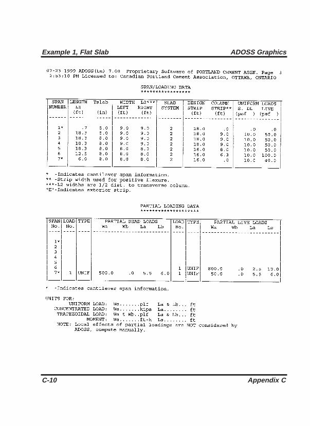
C-10 Appendix C
Example 1, Flat Slab ADOSS Graphics

Appendix C C-11
ADOSS Graphics Example 1, Flat Slab

C-12 Appendix C
Example 1, Flat Slab ADOSS Graphics

Appendix C C-13
ADOSS Graphics Example 1, Flat Slab

C-14 Appendix C
Example 1, Flat Slab ADOSS Graphics

Appendix C C-15
ADOSS Graphics Example 1, Flat Slab

C-16 Appendix C
Example 1, Flat Slab ADOSS Graphics

Appendix C C-17
ADOSS Graphics Example 1, Flat Slab

C-18 Appendix C
Example 1, Flat Slab ADOSS Graphics

Appendix C C-19
ADOSS Graphics Example 1, Flat Slab

C-20 Appendix C
Example 1, Flat Slab ADOSS Graphics

Appendix C C-21
ADOSS Graphics Example 1, Flat Slab

C-22 Appendix C
Example 1, Flat Slab ADOSS Graphics

Example 2, Beam- Supported Slab
Analyze and design an exterior strip shown in Figure C-2.
Figure C-2 Example beam-supported slab problem.
Appendix C C-23
ADOSS Graphics Example 2, Beam-Supported Slab

C-24 Appendix C
Example 2, Beam-Supported Slab ADOSS Graphics

Appendix C C-25
ADOSS Graphics Example 2, Beam-Supported Slab

C-26 Appendix C
Example 2, Beam-Supported Slab ADOSS Graphics

Appendix C C-27
ADOSS Graphics Example 2, Beam-Supported Slab

C-28 Appendix C
Example 2, Beam-Supported Slab ADOSS Graphics

Appendix C C-29
ADOSS Graphics Example 2, Beam-Supported Slab

C-30 Appendix C
Example 2, Beam-Supported Slab ADOSS Graphics

Appendix C C-31
ADOSS Graphics Example 2, Beam-Supported Slab

C-32 Appendix C
Example 2, Beam-Supported Slab ADOSS Graphics

Appendix C C-33
ADOSS Graphics Example 2, Beam-Supported Slab

C-34 Appendix C
Example 2, Beam-Supported Slab ADOSS Graphics

Appendix C C-35
ADOSS Graphics Example 2, Beam-Supported Slab

C-36 Appendix C
Example 2, Beam-Supported Slab ADOSS Graphics

Appendix C C-37
ADOSS Graphics Example 2, Beam-Supported Slab

C-38 Appendix C
Example 2, Beam-Supported Slab ADOSS Graphics

Appendix C C-39
ADOSS Graphics Example 2, Beam-Supported Slab

C-40 Appendix C
Example 2, Beam-Supported Slab ADOSS Graphics

Appendix C C-41
ADOSS Graphics Example 2, Beam-Supported Slab

C-42 Appendix C
Example 2, Beam-Supported Slab ADOSS Graphics

Appendix C C-43
ADOSS Graphics Example 2, Beam-Supported Slab

C-44 Appendix C
Example 2, Beam-Supported Slab ADOSS Graphics

Appendix C C-45
ADOSS Graphics Example 2, Beam-Supported Slab
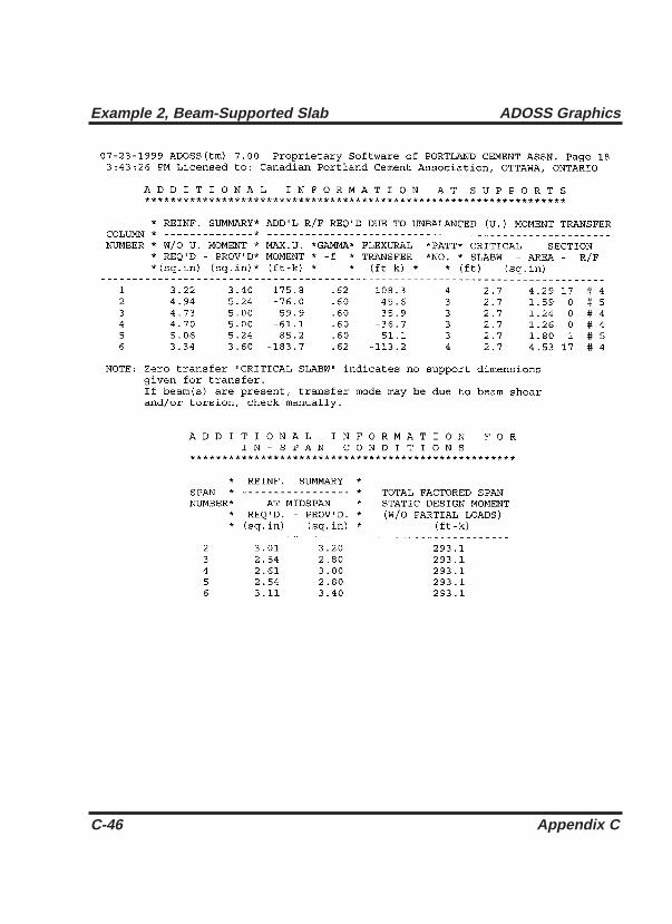
C-46 Appendix C
Example 2, Beam-Supported Slab ADOSS Graphics

Appendix C C-47
ADOSS Graphics Example 2, Beam-Supported Slab

Example 3, Continuous Beam
Analyze and design a continuos beam shown in Figure C-3.
Figure C-3 Example continuous beam problem
C-48 Appendix C
Example 3, Continuous Beam ADOSS Graphics

Appendix C C-49
ADOSS Graphics Example 3, Continuous Beam

C-50 Appendix C
Example 3, Continuous Beam ADOSS Graphics

Appendix C C-51
ADOSS Graphics Example 3, Continuous Beam

C-52 Appendix C
Example 3, Continuous Beam ADOSS Graphics

Appendix C C-53
ADOSS Graphics Example 3, Continuous Beam

C-54 Appendix C
Example 3, Continuous Beam ADOSS Graphics

Appendix C C-55
ADOSS Graphics Example 3, Continuous Beam

C-56 Appendix C
Example 3, Continuous Beam ADOSS Graphics

Appendix C C-57
ADOSS Graphics Example 3, Continuous Beam

C-58 Appendix C
Example 3, Continuous Beam ADOSS Graphics

Appendix C C-59
ADOSS Graphics Example 3, Continuous Beam

C-60 Appendix C
Example 3, Continuous Beam ADOSS Graphics

Appendix C C-61
ADOSS Graphics Example 3, Continuous Beam

C-62 Appendix C
Example 3, Continuous Beam ADOSS Graphics

Appendix C C-63
ADOSS Graphics Example 3, Continuous Beam
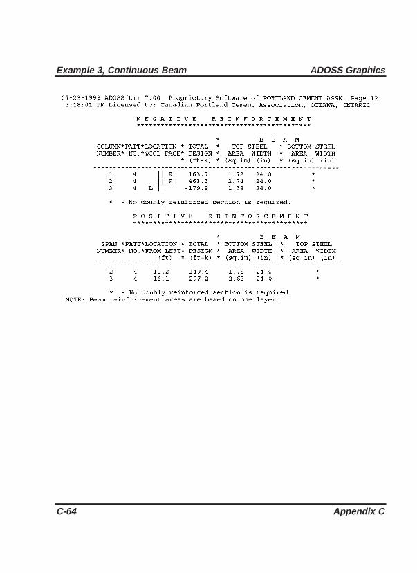
C-64 Appendix C
Example 3, Continuous Beam ADOSS Graphics

Appendix C C-65
ADOSS Graphics Example 3, Continuous Beam

C-66 Appendix C
Example 3, Continuous Beam ADOSS Graphics

Appendix C C-67
ADOSS Graphics Example 3, Continuous Beam

.ADS, 3-1
.OUT, 4-54
A
About ADOSS, 3-12, 4-65Ac, 2-10, 2-36 - 2-37, 2-44ACI, 4-12add mode, 4-17ADOSS icon, 1-10af, 2-60Al, 2-51alternate design, 4-14angles, 4-44Arrange Icons, 3-11As, 2-52, 2-54ASSIGN, 1-8astrip, 2-62At, 2-50aq, 2-62Atot, 2-22, 2-50Auto Input, 3-1, 3-4, 4-5Av, 2-46, 2-50a1, 2-32, 2-41, 2-43, 2-45, 2-48, 2-61as, 2-40
B
b1, 2-45b2, 2-45Back, 4-65Background Color, 3-9, 4-56backup copy, 1-5bar size
maximum, 4-14
metric, A-3minimum, 2-54, 4-14U.S., A-2
bar spacingmaximum, 2-54minimum, 2-53 - 2-54, 4-14
bc, 2-40Beam Reinforcement, 4-10, 4-14beam supported slab, 2-7, 2-45, 2-65beams
depth, 2-36edge, 2-7flange, 2-4shallow, 2-35T-beam, 2-2, 2-4, 2-23, 2-52 -
2-53transverse, 2-31
bo, 2-41box
check box, 4-4, 4-45, 4-46dialog, 4-3edit, 4-3
building code, 4-11building standard, 4-11buttons
Copy From, 4-16Delete, 4-39Insert, 4-38push, 4-5radio, 4-4, 4-56 - 4-59Replace, 4-17
bw, 2-46b1, 2-52b2, 2-32, 2-43, 2-48, 2-61
Index 1
Index

C
C, 2-18, 2-21, 2-32c1, 2-1, 4-28c2, 2-1, 2-21, 2-33, 4-28cantilever, 2-1, 2-62, 4-19, 4-25capitals, 2-1 - 2-2, 2-13, 2-31, 2-52,
2-59defining, 4-26depth, 4-27extension, 4-27
Cascade, 3-10, 4-65Change Isometric Angle, 3-6, 4-44,
4-61check box, 4-4, 4-45, 4-47checks
code, 2-2 - 2-7geometric, 2-1
CHKDSK, 1-5clear rib spacing, 4-21Close, 3-13code, 4-11
checks, 2-2 - 2-7, 5-3colors, 4-56 - 4-57
background, 3-9, 4-56 - 4-58loads, 3-9, 4-59members, 3-9, 4-59
Column Fixity, 3-5, 4-33changing, 4-33
columnsc1, 4-26c2, 4-26defining, 4-26designing, 4-50, 5-3equivalent, 2-15fixed, 4-33fixity, 4-17
height, 4-27pinned, 4-27 - 4-28, 4-32round, 4-26service loads, 4-50strip, 2-28, 2-31, 2-33 - 2-34,
2-51Columns/Capitals, 4-27commands, 3-11, 4-66
About ADOSS, 3-12, 4-68Arrange Icons, 3-11Auto Input, 3-1, 3-4, 4-6, 4-10Background Color, 3-9, 4-56Beam Reinforcement, 4-10,
4-14Cascade, 3-10, 4-65Change Isometric Angle, 3-6,
4-46, 4-65Close, 3-13Column Fixity, 3-5, 4-34Columns/Capitals, 4-26Commands, 3-11, 4-63Condense/Expand Output, 3-3,
3-8, 4-47, 4-54Default Data Directory, 1-9,
3-10, 4-60Default Units/Code, 1-8, 3-9,
4-56Design Column, 3-8, 4-50Design System, 3-8, 4-6, 4-50,
4-54 - 4-56disabled, 4-4Drops, 4-29enabled, 4-4Exit, 3-3Export, 3-2, 4-7Factors, 4-40, 4-41
2 Index
ADOSS Graphics

General Information, 3-4, 4-10-4-11, 4-16, 4-39, 4-62
Index, 3-11, 4-63Labels, 3-4, 4-9Lateral Forces, 4-40Lateral Moments, 4-41Load Colors, 3-9, 4-57Longitudinal Beams, 4-20,
4-22 - 4-24Material Properties, 3-4, 4-10,
4-13Maximize, 3-13Member Colors, 3-9, 4-59Minimize, 3-13More Windows, 4-61Move, 3-12New, 3-1, 4-5Next, 3-13Open, 3-1, 4-8, 4-63Page Layout, 3-10, 4-55, 4-56,
4-60Partial Loads, 4-34Print Results, 3-3, 4-52Print Screen, 3-3, 4-53, 4-54Procedures, 3-12, 4-63Redraw, 3-6, 4-43Restore, 3-12, 4-62Revert, 3-3Ribs, 4-21Save, 3-2, 4-6, 4-50, 4-54 -
4-56Save As, 3-2, 4-5Scale, 3-6, 4-43selecting, 4-3Size, 3-13Slab Geometry, 4-18Slab Reinforcement, 4-14
Surface Loads, 4-35Tile All Windows, 3-11, 4-62Tile View Windows, 3-11, 4-62Transverse Beams, 4-31Using Help, 3-12, 4-64View Deflections, 3-8, 4-55View Loads, 3-7, 4-48View Members, 3-7, 4-45View Results, 3-7, 4-52View Shears/Moments, 3-7,
4-53Zoom, 3-6, 4-45
concretecompressive strength, 2-11,
2-47, 4-13density, 2-8, 2-10 - 2-11, 4-12modulus of elasticity, 2-11modulus of rupture, 2-12, 4-12quantity, 2-67split tensile strength, 2-11,
2-41, 4-12type, 2-10, 2-41, 4-14
Condense/Expand Output, 3-3, 3-8, 4-49, 4-52
condensing output, 3-3, 4-41CONFIG.SYS, 1-2continuous beam, 2-8, 2-64 - 2-65Control menu, 3-12, 4-1, 4-62
Close, 3-13Maximize, 3-13Minimize, 3-13Move, 3-12Next, 3-13Restore, 3-12Size, 3-13
controls, 4-4check box, 4-4
Index 3
ADOSS Graphics

push button, 4-5radio buttons, 4-4
conversion factors, A-1Copy From button, 4-16 - 4-18cracking, 2-59, 2-64creep, 2-66critical section
closed, 2-36 - 2-38L-shaped, 2-39open, 2-37, 2-41U-shaped, 2-38CSA, 4-11Ct, 2-49
customer information, 1-9customizing, 4-59 - 4-63
D
data filescreating, 3-1, 3-4, 4-5old format, 3-2, 4-7opening, 3-2, 4-8saving, 3-2, 4-6working with, 4-5 - 4-8
date, 4-9db, 2-53default
code, 4-62data directory, 3-2, 4-60units, 4-62
Default Data Directory, 1-9, 3-10, 4-60Default Units/Code, 1-8, 3-9, 4-59definitions, 4-64deflections, 4-55
analysis, 2-12, 4-13, 5-10calculations, 2-59 - 2-66
diagrams, 4-6, 4-55instantaneous, 2-66lateral distribution factor, 2-60long time, 2-66midspan, 2-60 - 2-61printing, 3-3, 3-10, 4-51, 4-55viewing, 3-8, 4-55, 4-63
Delete button, 4-39density, 2-8, 2-10 - 2-11, 4-12depth
beam, 2-36capital, 4-27drop, 2-52, 4-29effective, 2-2, 2-36, 2-52longitudinal beam, 4-22 - 4-24rib, 4-21slab, 2-37transverse beam, 4-31
designcolumn, 4-50method, 4-12performing a, 4-49 - 4-52results, 4-54
Design Column, 3-8, 4-50Design menu, 3-8
Condense/Expand, 3-3Condense/Expand Output, 3-8,
4-47, 4-52Design Column, 3-8, 4-50Design System, 3-8, 4-6, 4-52,
4-56 - 4-58Design System, 3-8, 4-6, 4-52,
4-56 - 4-58designing, 4-50desktop, 4-51development length, 2-11, 4-13 - 4-14,
5-9
4 Index
ADOSS Graphics

DEVICE=, 1-2diagrams
deflections, 3-3, 3-8, 3-10, 4-6, 4-63
printing, 4-57shear and moment, 3-3, 3-7,
3-10, 4-6, 4-53, 4-56,4-65dialog box, 4-3directory
ADOSS, 1-6default data, 1-8root, 1-3subdirectory, 1-3
disk drives, 1-1disks, 1-5drops, 2-14 - 2-15, 2-40, 2-59, 4-29
defining, 4-29depth, 2-52, 4-30length, 4-30standard, 4-29valid, 2-2, 2-7waffle depth, 2-9width, 4-30
E
Ec, 2-60Ecb, 2-32eccentricity
transverse beam, 4-31Ecs, 2-18, 2-32edge
discontinuous, 2-7edit box, 4-3elevated view, 3-3, 3-10, 4-51, 4-62 -
4-63engineer, 4-10enhanced mode, 1-5epoxy-coated, 2-57, 4-13, 5-9equivalent frame method, 2-12, 2-21,2-60 - 2-61examples, C-1 - C-63Exit, 3-3expanding output, 4-47Export, 3-2, 4-7extension
capital, 4-26exterior, 4-12, 4-22
F
factors, 4-40, 4-42conversion, A-1distribution, 2-31 - 2-33, 5-5 - 5-6,f9c 2-11, 2-52, 4-14fct, 2-10 - 2-11, 2-41, 4-13File menu, 3-1
Exit, 3-3Export, 3-2, 4-7New, 3-1, 4-5Open, 3-1, 4-8, 4-62Print Results, 3-3, 4-55Print Screen, 3-3, 4-57 - 4-58,
4-60Revert, 3-3Save, 3-2, 4-6, 4-50, 4-54 -
4-55Save As, 3-2, 4-6
fixed, 4-33fixity, 4-17
Index 5
ADOSS Graphics

flangedepth, 4-22overhang, 2-4width, 2-23
flat plate, 2-7, 2-34, 2-64 - 2-65flat slab, 2-7, 2-34, 2-64 - 2-65floor system, 4-10
creating, 4-9modeling, 4-10specifying, 4-11forces, 4-11, 4-38
formworkquantity, 2-67, 5-10
fr, 2-12, 4-14fy, 2-52, 4-14fyv, 2-46, 4-14
G
General Information, 3-4, 4-10, 4-14, 4-38, 4-61
printout, 5-2using, 4-11
geometry, 4-18defining, 4-16
Geometry menu, 3-5, 4-10, 4-12, 4-16Columns/Capitals, 4-27Drops, 4-30Longitudinal Beams, 4-20,
4-22 - 4-24Ribs, 4-21Slabs, 4-18Transverse Beams, 4-30
gf, 2-58gv, 2-44
H
haunched beam, 4-23height
column, 4-28help, 4-66Help menu, 3-11, 4-63
About ADOSS, 3-12, 4-65Commands, 3-11, 4-63Index, 3-11, 4-62Procedures, 3-12, 4-63Using Help, 3-12, 4-65
help systemBack, 4-64Index, 4-64Search, 4-64
I
Ie, 2-64 - 2-65Iframe, 2-60Ig, 2-65Index, 3-11, 4-63 - 4-64inflection points, 2-56, 5-4input echo, 4-50, 5-2Input menu, 3-4
Auto Input, 3-1, 3-4, 4-6, 4-10Column Fixity, 3-5, 4-33General Information, 3-4, 4-10-
4-11, 4-16, 4-39, 4-64Labels, 3-4, 4-9Material Properties, 3-4, 4-10,
4-12Insert button, 4-37installing, 1-6 - 1-11interior, 4-11, 4-21
6 Index
ADOSS Graphics

Is, 2-21, 2-32Isb, 2-21isometric view, 3-3, 3-6, 3-10, 4-44
changing angle, 4-44
J
Jc, 2-44
K
Kec, 2-22Kt, 2-18, 2-21, 2-48Kta, 2-21
L
l1, 2-28, 2-31, 2-46l2, 2-21, 2-28, 2-33Labels, 3-4, 4-9lateral factors, 4-51Lateral Forces, 4-38lateral loads
portal analysis, 4-38specifying, 4-12, 4-38
Lateral Moments, 4-39layer, 4-16lc, 2-15length
drop, 4-31haunch, 4-25span, 4-19, 4-24 - 4-25
limit states, 4-11Load Colors, 3-9, 4-59loads
additional, 4-50
applied, 2-22colors, 3-9column service, 4-47combination, 2-27concentrated, 2-45dead to live, 2-13factors, 4-42gravity, 5-4hiding, 4-48lateral, 2-23, 2-25, 2-33 - 2-34, 2-45, 4-11, 4-39, 5-4, 5-6moments, 4-35partial, 2-23, 2-41, 2-59, 4-20 -
4-22, 4-34 - 4-39, 4-48patterns, 2-15, 2-25, 3-7, 4-11,
4-56portal analysis, 4-38reduction factor, 4-40self-weight, 2-3 - 2-4, 2-22,
2-41specifying, 4-35 - 4-41superimposed, 2-22surface, 2-41, 4-18, 4-35transverse beam, 2-47trapezoidal, 4-36uniform, 4-35
Loads menu, 3-5, 4-10, 4-11Factors, 4-40, 4-43Lateral Forces, 4-38Lateral Moments, 4-38Partial Loads, 4-36Surface Loads, 4-34
location, 4-12longitudinal beam
defining, 4-22depth, 4-22 - 4-24haunched, 4-24
Index 7
ADOSS Graphics

shear, 2-45 - 2-46, 5-7width, 4-22 - 4-24
Longitudinal Beams, 4-18, 4-22 - 4-24
M
margins, 3-10, 4-57, 4-59Material Properties, 2-10 - 2-11, 3-4,
4-10defining, 4-12
material quantities, 2-67, 4-49, 5-10Maximize, 3-13maximums
bar size, 4-14bar spacing, 2-54
Mcr, 2-65Member Colors, 3-9, 4-57members
colors, 3-9, 4-57hiding, 4-44menu line, 4-2
menusaccessing, 4-2closing, 4-3commands, 4-3Control, 3-12, 4-1, 4-63Design, 3-8File, 3-1, 4-5Geometry, 3-5, 4-10, 4-11Help, 3-11Input, 3-4Loads, 3-5, 4-10, 4-11Options, 3-9pop-up, 4-2Reinforcement, 3-5, 4-10, 4-13View , 3-6
Window, 3-10, 4-53, 4-57 -4-58, 4-62 - 4-63message, 2-7 - 2-8, 2-52, 4-50middle strip, 2-28, 2-31, 2-33 - 2-34,
2-51Minimize, 3-13minimums
bar size, 2-54, 4-15bar spacing, 2-54, 4-15
modeling, 4-9modulus of elasticity
concrete, 2-11reinforcement, 2-12
modulus of rupture, 2-12, 4-13moment
beam, 2-33 - 2-34centerline, 4-50column, 4-53column strip, 2-31cracking, 2-65design, 2-23, 2-31 - 2-33, 2-51,
4-51, 5-5 - 5-6diagram, 3-7, 3-10, 4-6, 4-54,
4-54, 4-63lateral analysis, 4-12, 4-38middle strip, 2-33 - 2-34negative, 2-51printing, 4-55, 5-5proportioned, 2-41, 2-43, 2-45,
2-48segmental, 4-50, 5-5total static, 2-59transfer, 2-59unbalanced, 2-42
moment of inertia, 2-13effective, 2-64 - 2-65gross, 2-65
8 Index
ADOSS Graphics

More Windows, 4-65Move, 3-12Mu, 2-51, 2-58Munbal, 2-42, 2-44, 2-48
N
New, 3-1, 4-5Next, 3-13number of spans, 4-10
O
one-way slab, 2-8, 2-64 - 2-65Open, 3-1, 4-8, 4-63optimize, 4-9Option menu
Page Layout, 4-57options
code, 1-8default, 1-8units, 1-8
Options menu, 3-9Background Color, 3-9, 4-57Default Data Directory, 1-9,
3-10, 4-61Default Units/Code, 1-8, 3-9,
4-59Load Colors, 3-9, 4-59Member Colors, 3-9, 4-58Page Layout, 3-10, 4-59, 4-64
outputcondense, 4-47expand, 4-47
P
Pa, 4-40Page Layout, 3-10, 4-55, 4-59, 4-62partial loads, 2-41, 2-59, 4-18, 4-20
changing, 4-35deleting, 4-35hiding, 4-46inserting, 4-34specifying, 4-34PATH, 1-3, 3-8, 4-50
Pb, 4-40PCA Programs, 1-10PCA SETUP, 1-6PCA View, 3-7, 4-52PCACOL, 3-8, 4-52, 4-52, 5-3PCAPROGS.INI, 1-8, 3-9, 4-59 - 4-61,
4-62pinned, 4-28 - 4-29, 4-34plan view, 3-3, 3-10, 4-64 - 4-62portal analysis, 2-23print, 4-56, 4-58Print Results, 3-3, 4-57Print Screen, 3-3, 4-55printing
deflections, 4-55results, 4-52shear and moment, 4-54
Procedures, 3-12, 4-63project id, 4-9proportioned moments and shears, 2-41,2-43, 2-45, 2-48, 4-13push buttons, 4-5
Index 9
ADOSS Graphics

Q
quantities, 2-67, 5-10
R
radio buttons, 4-4, 4-51README, 1-10Redraw, 3-6, 4-43reduction factor, 4-39references, B-1reinforcement
additional, 2-58, 4-49, 5-9bend, 2-54cover, 2-54defining, 4-15development length, 2-11, 4-13
- 4-15, 5-9distance to centroid, 4-15epoxy-coated, 2-57, 4-13, 5-9layer, 2-54, 4-16maximum bar size, 4-13maximum spacing, 2-54metric, 4-11minimum, 2-53minimum bar size, 2-54, 4-13minimum spacing, 2-53 - 2-54,
4-15negative, 5-8positive, 5-8quantity, 2-67, 5-10required, 4-51schedule, 2-59, 4-49, 5-8yield strength, 2-46, 4-13
Reinforcement menu, 3-5, 4-10, 4-13Beams, 4-10
Slabs, 4-10Replace button, 4-16requirements
hardware, 1-5software, 1-5
Restore, 3-12, 4-65results
printing, 4-52viewing, 4-52
Revert, 3-3ribs
clear spacing, 4-22defining, 4-21depth, 4-22valid, 2-4, 2-40width, 4-22
Ribs Geometry, 4-22run, 1-11running ADOSS, 1-11rb, 2-52rmin, 2-53
S
Save, 3-2, 4-6, 4-50, 4-54Save As, 3-2, 4-6Scale, 3-6, 4-42Search, 4-64segmental
envelopes, 5-5moments, 4-50, 5-5
shears, 5-5self-weight, 2-3 - 2-4, 2-22, 2-41, 4-34shear
allowable, 2-39, 2-45area, 2-35
10 Index
ADOSS Graphics

centerline, 4-48column, 4-51diagram, 3-3, 3-7, 3-10, 4-6,
4-52, 4-65direct, 4-51longitudinal beam, 2-45 - 2-46,
5-7moment transfer, 2-35, 2-49one-way, 2-34, 2-36printing, 4-57, 5-7proportioned, 2-41, 2-43, 2-45,
2-48punching, 2-34 - 2-35, 2-45,
5-7segmental, 4-50, 5-5transverse beam, 2-47wide beam, 2-34
shear/moment transfer, 2-34shrinkage, 2-66SI, 4-11sign convention, 2-24Size, 3-13Slab Geometry, 4-18Slab Reinforcement, 4-10, 4-14slabs
defining, 4-18thickness, 4-22
soffit, 2-1, 2-4span
length, 4-18, 4-23width, 4-22
span id, 4-10split tensile strength, 2-11, 2-41, 4-13standard drop, 4-29stiffness, 2-13
beam, 2-4capital, 2-4
column, 2-15drop, 2-3torsional, 2-15waffle , 2-9
stirrup, 2-46 - 2-47STMFR II, 2-23strength design, 4-11strips
beam, 2-51column, 2-28, 2-31, 2-33 -
2-34, 2-51middle, 2-28, 2-31, 2-33 -
2-34, 2-51surface loads, 2-41, 4-18, 4-33
specifying, 4-32
T
T-beam, 2-2, 2-4, 2-23, 2-52 - 2-53, 4-21
Tc, 2-49 - 2-50thickness
minimum, 2-6 - 2-7slab, 2-52waffle slab, 2-9
Tile All Windows, 3-11, 4-63Tile View Windows, 3-11, 4-63time, 4-10title bar, 4-1torque, 2-47 - 2-48torsiontransverse beam, 2-47transverse beam
defining, 4-31depth, 4-31eccentricity, 4-32
Index 11
ADOSS Graphics

shear, 2-47 - 2-50, 5-7torsion, 2-47 - 2-50, 5-7width, 4-30
Transverse Beams, 4-30Tu, 2-48, 2-50type, 4-14
U
units, 4-11Untitled, 4-5UNTITLED.ADS, 4-6UNTITLED.OUT, 4-54US, 4-11Using Help, 3-12, 4-68
V
validdrops, 2-2, 2-7ribs, 2-4, 2-41
Vc, 2-11, 2-40 - 2-41, 2-46, 2-50version, 4-68, 5-2view
elevated, 3-3, 4-62isometric, 3-3, 4-44, 4-64plan, 3-3, 4-62
View Deflections, 3-8, 4-58View Loads, 3-7, 4-48View Members, 3-7, 4-47View menu, 3-6
Change Isometric Angle, 3-6, 4-44, 4-63
Redraw, 3-6, 4-46Restore, 4-65Scale, 3-6, 4-43
View Deflections, 3-8, 4-56View Loads, 3-7, 4-46View Members, 3-7, 4-46View Results, 3-7, 4-54View Shears/Moments, 3-7,
4-54Zoom, 3-6, 4-43
View Results, 3-7, 4-52View Shears/Moments, 3-7, 4-54viewing
deflections, 4-57floor system, 4-42results, 4-52scale, 4-42shears and moments, 4-54
viewselevated, 3-10, 4-53isometric, 3-6, 3-10plan, 3-10
Vu, 2-41, 2-43, 2-45 - 2-50
W
waffle slab, 2-2, 2-7, 2-34, 2-64 - 2-65,4-22, 4-30, 4-32
ribs, 2-4special considerations, 2-8 -
2-9wbend, 2-54width
drop, 4-32effective slab, 2-58longitudinal beam, 4-23ribs, 4-22span, 4-21transverse beams, 4-31
12 Index
ADOSS Graphics

wind, 2-27, 4-12, 4-40Window menu, 3-10, 4-52
Arrange Icons, 3-11Cascade, 3-10, 4-63More Windows, 4-65Tile All Windows, 3-11, 4-62Tile View Windows, 3-11, 4-62
windowsdeflections, 3-3, 3-8, 3-10,
4-55elevated view, 3-3, 3-10, 4-51isometric view, 3-3, 3-6, 3-10,
4-61opening, 4-62partial loads, 4-62plan view, 3-3, 3-10, 4-61shear and moment, 3-3, 3-7,
3-10, 4-55surface loads, 4-62working with, 4-64
X
x, 2-21, 2-48x1, 2-50
Y
y, 2-21, 2-48y1, 2-50yield strength, 4-14
Z
Zoom, 3-6, 4-45zooming, 4-45
Index 13
ADOSS Graphics