ac review discussion d12.2. passive circuit elements i i i + -
Post on 21-Dec-2015
220 views
TRANSCRIPT

AC Review
Discussion D12.2

Passive Circuit Elements
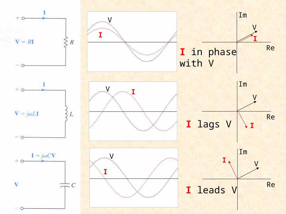
v iR
1i v
R
div L
dt
1i vdt
L
1v idt
C
dvi C
dt
+
-
Rv
+
-
Lv
+
-
Cv
ii
i+
-

Energy stored in the capacitor
The instantaneous power delivered to the capacitor is
( )t tdv
w p t dt C v dt C vdvdt
( )dv
p t vi Cvdt
The energy stored in the capacitor is thus
21( ) joules
2w Cv t

Energy stored in the capacitor
221 ( )( )
2 2
q tw Cv t
C
q CvAssuming the capacitor was uncharged at t = -, and knowing that
represents the energy stored in the electric field established between the two plates of the capacitor. This energy can be retrieved. And, in fact, the word capacitor is derived from this element’s ability (or capacity) to store energy.

Parallel Capacitors
i1i 2i Ni
1C 2C NCv+
-
ii
eqCv+
-
1 1
dvi C
dt 2 2
dvi C
dt N N
dvi C
dt
1 2 1 2N N eq
dv dvi i i i C C C C
dt dt
1
N
eq kk
C C
Thus, the equivalent capacitance of N capacitors in parallel is the sum of the individual capacitances. Capacitors in parallel act like resistors in series.
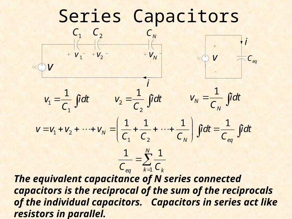
Series Capacitors
11
1v idt
C
1 21 2
1 1 1 1N
N eq
v v v v idt idtC C C C
1
1 1N
keq kC C
The equivalent capacitance of N series connected capacitors is the reciprocal of the sum of the reciprocals of the individual capacitors. Capacitors in series act like resistors in parallel.
DC
1v 2v Nv
1C 2C NC
vi
+ + + -- -
i
eqCv+
-
DC
22
1v idt
C
1N
N
v idtC

Energy stored in an inductor
The instantaneous power delivered to an inductor is
( ) ( )t t
L
diw t p t dt L i dt L idi
dt
( )di
p t vi Lidt
The energy stored in the magnetic field is thus
21( ) ( ) joules
2Lw t Li t

Series Inductors
1 1
div L
dt 2 2
div L
dt N N
div L
dt
1 2 1 2N N eq
di div v v v L L L L
dt dt
1
N
eq kk
L L
The equivalent inductance of series connected inductors is the sum of the individual inductances. Thus, inductances in series combine in the same way as resistors in series.
DC
1L 2L NL
1v 2v Nv+ + + -- -
v
i
i
eqLv+
-
DC

Parallel Inductors
11
1i vdt
L
1 21 2
1 1 1 1N
N eq
i i i i vdt vdtL L L L
1
1 1N
keq kL L
The equivalent inductance of parallel connected inductors is the reciprocal of the sum of the reciprocals of the individual inductances.
22
1i vdt
L
1N
N
i vdtL
1i 2i Ni
1L 2L NLv+
-
i
i
v+
-
eqLi

Complex Numbers
real
imag
A
x jy A
jAe A
1tany
x
cos sinje j Euler's equation:
cos sinA jA A
2 2A x y
cosx A
siny A
ComplexPlane
measured positivecounter-clockwise
cos sinj j je e e j
Note:

sin cos2
t t
cos sin2
t t
sin sint t
cos cost t
tt
t = 0
0 0
t = 0
ReRe
Im Im
cos
sin
Phasor projectionon the real axis
cos( )t
sin( )t
sin sin cos cos sint t t
cos cos cos sin sint t t
Relationship between sin and cos

Comparing Sinusoids
sin 45 cos 135t t
sin cos2
t t
cos cost t
sin sint t
Note: positive angles are counter-clockwise
cos sin2
t t
cos sin by 90t t leads
cos - sin by 90t t lags
sin t
Re
Im
cos t
-sin t
-cos t
sin t
Re
Im
cos t
45
45
135
cos 45 cos by 45 and sin by 135t t t leads leads

Phasors
jM MX e X X
XM
Recall that when we substituted j te
cancelled out.
We are therefore left with just the phasors
A phasor is a complex number that represents the amplitude and phase of a sinusoid.
( ) j tMi t I e
in the differential equations, the

Impedance
Impedancephasor voltage
phasor current
VZ
I
2 2 2Z R L
R j L
V
I
zR j L Z V
ZI
1tanz
L
R
Note that impedance is a complex number containing a real, or resistive component, and an imaginary, or reactive, component.
Units = ohms
AC
R
LcosMV t
i(t)
+
-
VR
VL
+ -
-
+
R jX Z
resistanceR
reactanceX

Admittance
Admittance1 phasor current
phasor voltage
IY = =
Z V
2 2 2
RG
R L
R j L
V
I
2 2 2
1 R j LG jB
R j L R L
I
Y =V
conductance
Units = siemens
susceptance2 2 2
LB
R L
AC
R
LcosMV t
i(t)
+
-
VR
VL
+ -
-
+
Re
Im
Re
Im
Re
Im
V
V
V
V
V
V
I
I
I
I
I
I
I in phasewith V
I lags V
I leads V

Z1
DC
Z2
Z3 Z4I1
I2V
I
Zin
3 41 2
3 4in
Z Z
Z Z ZZ Z
We see that if we replace Z by R the impedances add like resistances.
Impedances in series add like resistors in series
Impedances in parallel add like resistors in parallel

Voltage DivisionZ1
DCZ2
+
VI
V1
V2
+
-
-1 2
V
IZ Z
1 1V Z I
2 2V Z I
But
Therefore
11
1 2
Z
V VZ Z
22
1 2
Z
V VZ Z

Instantaneous Power
( ) cosM vv t V t
( ) cosM ii t I t
( ) ( ) ( ) cos cosM M v ip t v t i t V I t t
( ) cos cos 22
M Mv i v i
V Ip t t
Note twice the frequency

Average Power
0 0
0 0
1 1( ) cos cos
t T t T
M M v it tP p t dt V I t t dt
T T
0
0
1cos cos 2
2
t TM M
v i v it
V IP t dt
T
2T
1 cos2 M M v iP V I
0v i 90v i Purely resistive circuit Purely reactive circuit
12 M MP V I 1 cos 90 02 M MP V I

Effective or RMS ValuesWe define the effective or rms value of a periodic current (voltage) source to be the dc current (voltage) that delivers the same average power to a resistor.
0
0
2 21( )
t T
eff tP I R i t Rdt
T
0
0
21( )
t T
eff tI i t dt
T
eff rmsI I root-mean-square
0
0
2 21 ( )t Teff
t
V v tP dt
R T R
0
0
21( )
t T
eff tV v t dt
T
eff rmsV V

Effective or RMS Values
( ) cosM vv t V t
1
22
01 1 cos 2 22 22rms M vV V t dt
2 1 1cos cos 22 2 2T
0
0
21( )
t T
rms tV v t dt
T
11 2 2
22
00
1
2 2 2 2 2M
rms M M
VtV V dt V
Using and

Ideal Transformer - Voltage
1 1( )d
v t Ndt
2 2( )d
v t Ndt
1 1 1
2 2 2
dv N Ndt
dv N Ndt
22 1
1
Nv v
N
11
1( )v t dt
N
The input AC voltage, v1, produces a flux
This changing flux through coil 2 induces a voltage, v2 across coil 2
1v 2v
2i1i
+ +
- -2N1NAC Load

Ideal Transformer - Current
12 1
2
Ni i
N
The total mmf applied to core is
NiF
Magnetomotive force, mmf
1 1 2 2N i N i F R
For ideal transformer, the reluctance R is zero.
1 1 2 2N i N i
1v 2v
2i1i
+ +
- -2N1NAC Load

Ideal Transformer - Impedance
11 2
2
N
NV V
Input impedance
2
2L
VZ
I
21 2
1
N
NI I
1v 2v
2i1i
+ +
- -2N1NAC Load
Load impedance
1
1i
VZ
I
2
1
2i L
N
N
Z Z
2L
i n
ZZ 2
1
Nn
NTurns ratio

Ideal Transformer - Power
12 1
2
Ni i
N
Power delivered to primary
P vi
22 1
1
Nv v
N
1 1 1P v i
1v 2v
2i1i
+ +
- -2N1NAC Load
Power delivered to load
2 2 2P v i
2 2 2 1 1 1P v i v i P
Power delivered to an ideal transformer by the source is transferred to the load.

Force on current in a magnetic field( )q v F BForce on moving charge q -- Lorentz force
Current density, j, is the amount of charge passing per unit area per unit time. N = number of charges, q, per unit volume moving with mean velocity, v.
v t
Sj
j Nqv
( )N V q v F B
( ) V F j B
L
dQ Nq Sv ti j S
dt t
V S L
( ) L F i B
i BForce per unit length on a wire is

Rotating Machine
B
i
i
X
Force in
Force out
+-
brushes
commutator

B
i
iX
Force in
Force out
+-
X
r
B
2 cosw r
flux 2 cosA rl B Β
area 2 cosA lw l r
l
d
dt
emf flux 2 cos d rlt t
E s B
emf 2 sin 2 sinabe rl rlt
B B
a
b
Back emf

2 sinabe rl B
Back emf
abe
B
i
i
X
Force in
Force out
+-
brushes
commutator

Armature with four coil loops
XXX
X
abe
N
S

aE
aR
tV
aI
Motor Circuit
t a a aV E I R
a aE K
Power and Torque
d a a dP E I
/a t a aI V E R
d a aK I
/a t a aI V K R
2at ad
a a
KV K
R R