aaaaaaaa motorgas tech review
TRANSCRIPT
8/9/2019 AAAAAAAA MotorGas Tech Review
http://slidepdf.com/reader/full/aaaaaaaa-motorgas-tech-review 1/124
Motor Gasolines Technical Review
8/9/2019 AAAAAAAA MotorGas Tech Review
http://slidepdf.com/reader/full/aaaaaaaa-motorgas-tech-review 2/124
The products and processes referred to in this document are trademarks, registered
trademarks, or service marks of their respective companies or markholders.
Written, edited, and designed by employees and contractors of Chevron Corporation:
Lew Gibbs, Bob Anderson, Kevin Barnes, Greg Engeler, John Freel, Jerry Horn, Mike Ingham,
David Kohler, David Lesnini, Rory MacArthur, Mieke Mortier, Dick Peyla, Brian Taniguchi,
Andrea Tiedemann, Steve Welstand, David Bernhardt, Karilyn Collini, Andrea Farr,
Jacqueline Jones, John Lind, and Claire Tom. Chapter 5 prepared by Jack Benson
of AFE Consulting Services.
Motor Gasolines Technical Review (FTR-1)
© 2009 Chevron Corporation. All rights reserved.
8/9/2019 AAAAAAAA MotorGas Tech Review
http://slidepdf.com/reader/full/aaaaaaaa-motorgas-tech-review 3/124
Motor Gasolines Technical Review

8/9/2019 AAAAAAAA MotorGas Tech Review
http://slidepdf.com/reader/full/aaaaaaaa-motorgas-tech-review 4/124
8/9/2019 AAAAAAAA MotorGas Tech Review
http://slidepdf.com/reader/full/aaaaaaaa-motorgas-tech-review 5/124
Introduction . . . . . . . . . . . . . . . . . . . . . . . . . . . . . . . . . . . . . . . i
1 • Gasoline and Driving Performance. . . . . . . . . . . . . . . . 1
Volatility
Vapor Pressure
Distillation Profile
Vapor-Liquid Ratio
Vapor Lock Index
Driveability Index
Volatility Specifications
Antiknock Performance
Octane Number Requirement
Power Fuel Economy
Factors Affecting Fuel Economy
Fuel Economy Road Test
Other Performance Factors
2 • Gasoline and Air Quality . . . . . . . . . . . . . . . . . . . . . . . 13
Progress in the United States
Legislation
Administration/Regulation
Air Quality Standards
Air Pollutants
Origin of Vehicle Emissions
Vehicle Emissions: Limits
Inspection and Maintenance Vehicle Emissions: Gasoline Effects
Reformulated Gasolines
European Union
Japan
3 • Gasoline Refining and Testing . . . . . . . . . . . . . . . . . . 31
Composition
About Hydrocarbons
Refining
Raw Material
Refining Processes
The Modern Refinery
Processing Changes Required by
Air Pollution Regulations Blending
Contamination and Adulteration
Gasoline Additives
Specifications
4 • Oxygenated Gasoline . . . . . . . . . . . . . . . . . . . . . . . . . . 53
Chemistry
Use
Sources
Specifications
Performance Issues
5 • Gasoline Engines and Selected Systems . . . . . . . . . 61
Conventional Engine Technology
Combustion Cycle
Engine Structure
Air System
Intake Air Pressurizing
Positive Crankcase Ventilation
Fuel System
Carburetors
Injectors
Storage
Exhaust System
Catalytic Converter
Exhaust Gas Recirculation
Control Systems
Fuel Control
Spark Control
On-board Diagnostics
Advanced Engine Technology
Conventional Engine Modifications
Direct Injection
Variable Valve Timing
Cylinder Deactivation
Variable Compression Ratio
Controlled Autoignition Combustion
Alternative Engine Technology
Hybrid Gasoline-Electric
Fuel Cell Electric
6 • Gasoline Vehicles — Deposit Control. . . . . . . . . . . . . 77
Engine Deposits and Performance
Historical Development of Deposit Control Additives
No Harm and Compatibility
Emissions
Required Additive Use
TOP TIER Detergent Gasoline
Aftermarket Additives
Handling Gasoline Safely . . . . . . . . . . . . . . . . . . . . . . . . . . 83
Questions and Answers . . . . . . . . . . . . . . . . . . . . . . . . . . . 89
Sources of More Information. . . . . . . . . . . . . . . . . . . . . . . 95
Abbreviations. . . . . . . . . . . . . . . . . . . . . . . . . . . . . . . . . . . . 99
Index . . . . . . . . . . . . . . . . . . . . . . . . . . . . . . . . . . . . . . . . . . 103
Table of Contents

8/9/2019 AAAAAAAA MotorGas Tech Review
http://slidepdf.com/reader/full/aaaaaaaa-motorgas-tech-review 6/124
8/9/2019 AAAAAAAA MotorGas Tech Review
http://slidepdf.com/reader/full/aaaaaaaa-motorgas-tech-review 7/124
i
In May 1876, Nicolaus Otto built the first practical four-stroke-cycle internal combustion
engine powered by a liquid fuel. By 1884, he concluded development of his engine with the
invention of the first magneto ignition system for low-voltage ignition. The liquid fuel used by
Otto became known as gasoline in the United States; elsewhere it may be known as gasolina,
petrol , essence, or benzin (not to be confused with the chemical compound benzene).
Although the U.S. petroleum industry was almost 50 years old when the first Model T
rolled off Henry Ford’s production line in 1908, gasoline and the automobile grew up
together. The industry was born in August 1859 near Titusville, Pa., when a drilling effort
financed by Edwin Drake hit crude oil at a depth of 70 feet (21 meters). The major product
in the early years wasn’t gasoline; it was lamp oil, called coal oil or kerosene.1 People were
reading more and wanted better light than that provided by candles and whale oil lamps.
The natural gasoline in crude oil was a surplus byproduct. Being too volatile to use in
lamps, it was burned at refineries, dumped, or converted to a gaseous fuel for gas lights.
The development of the electric light and the astonishing popularity of the automobile in
the first decades of the 20th century turned the petroleum industry’s focus from kerosene
to gasoline. In 1911, gasoline sales exceeded kerosene sales for the first time. The simple
engines in the first cars ran on almost any liquid that burned. As the demand for power
increased and engines became more sophisticated, gasoline was recognized as the right fuel
for the spark-ignition internal combustion engine.2
Drivers can obtain the performance they expect only when the characteristics of the fuel theyuse match the fuel requirements of the engines in their cars. As a result of this correlation,
the gasoline engine and its fuel matured as mutually dependent partners. An engine was not
designed without considering the gasolines available in the marketplace. In turn, gasoline
was not made without considering the requirements of the engines that would burn it. The
partnership became a triumvirate in the last decades of the 20th century as environmental
considerations began to change both engine design and gasoline characteristics.
This review collects information about all three members of the triumvirate in one place.
The major focus is gasoline – its performance, characteristics, refining and testing, and
safe use. Significant space is also devoted to the operation of modern engines and to the
impact of environmental regulations on both engines and fuels. Numerous cross-references
emphasize how interconnected these topics are. We hope readers will find the review a
source of valuable information, whether they read it from cover to cover or focus on an
area of interest.
Please note: The information in this review may be superseded by new regulations or
advances in fuel or engine technology.
Introduction
1 Both the names coal oil and kerosene were holdovers from the previous decades when lamp oil was
distilled from coal. Kerosene, a corruption of the Greek words for wax and oil, was one American
company’s brand name for coal oil.
2 Petroleum Panorama, The Oil and Gas Journal , 57 (5), January 28, 1959.

8/9/2019 AAAAAAAA MotorGas Tech Review
http://slidepdf.com/reader/full/aaaaaaaa-motorgas-tech-review 8/124
8/9/2019 AAAAAAAA MotorGas Tech Review
http://slidepdf.com/reader/full/aaaaaaaa-motorgas-tech-review 9/124
1
When drivers think about gasoline, their thoughts rarely go beyond filling up or checking
prices. Because gasoline almost always performs well, drivers forget what a sophisticated
product it is. More thought would reveal a demanding set of performance expectations:
• An engine that starts easily when cold, warms up rapidly, and runs smoothly
under all conditions.
• An engine that delivers adequate power without knocking.
• A vehicle that provides good fuel economy and generates low emissions.
• A gasoline that does not add to engine deposits or contaminate or corrode
a vehicle’s fuel system.
Although proper vehicle design and maintenance are necessary, gasoline plays an important
role in meeting these expectations.
This chapter discusses how gasoline’s characteristics affect driving performance.
VOLATILITY
Driveability describes how an engine starts, warms up, and runs. It is the assessment
of a vehicle’s response to the use of its accelerator relative to what a driver expects.
Driveability problems include hard starting, backfiring, rough idling, poor throttle
response, and stalling (at idle, under load, or when decelerating).
The key gasoline characteristic for good driveability is volatility – a gasoline’s tendency to
vaporize. Volatility is important because liquids and solids don’t burn; only vapors burn.
When a liquid appears to be burning, actually it is the invisible vapor above its surface that
is burning. This rule holds true in the combustion chamber of an engine; gasoline must
be vaporized before it can burn. For winter weather, gasoline blenders formulate gasoline
to vaporize easily. Gasoline that vaporizes easily allows a cold engine to start quickly and
warm up smoothly. Warm-weather gasoline is blended to vaporize less easily to prevent
engine vapor lock and other hot fuel handling problems and to control evaporative
emissions that contribute to air pollution.
It is important to note that there is no single best volatility for gasoline. Volatility must be
adjusted for the altitude and seasonal temperature of the location where the gasoline will beused. Later, this chapter will explain how gasoline specifications address this requirement.
Three properties are used to measure gasoline volatility in the United States: vapor pres-
sure, distillation profile, and vapor-liquid ratio. A fourth property, driveability index, is
calculated from the distillation profile. Instead of a vapor-liquid ratio, a vapor lock index
is used outside the U.S. to control hot fuel handling problems.
1
1 • Gasoline and Driving Performance
8/9/2019 AAAAAAAA MotorGas Tech Review
http://slidepdf.com/reader/full/aaaaaaaa-motorgas-tech-review 10/124
Vapor Pressure
With respect to gasoline, vapor pressure (VP) is the single most important property
for cold-start and warm-up driveability. (Cold-start means that the engine is at ambient
temperature, not that the ambient temperature is cold.) When gasoline vapor pressure is
low, an engine may have to be cranked a long time before it starts. When vapor pressure is
extremely low, an engine may not start at all. Engines with port fuel injection (see page 66)
appear to start more readily with low vapor pressure fuel than do carbureted engines. Vapor
pressure varies with the season; the normal range is 48.2 kPa to 103 kPa (7 psi to 15 psi).
Higher values of vapor pressure generally result in better cold-start performance, but lower
values are better to prevent vapor lock and other hot fuel handling problems.
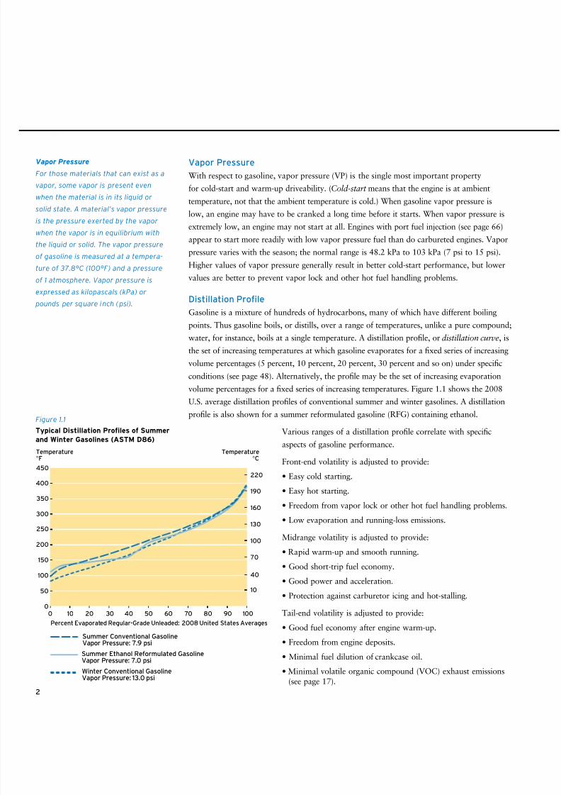
Distillation Profile
Gasoline is a mixture of hundreds of hydrocarbons, many of which have different boiling
points. Thus gasoline boils, or distills, over a range of temperatures, unlike a pure compound;
water, for instance, boils at a single temperature. A distillation profile, or distillation curve, is
the set of increasing temperatures at which gasoline evaporates for a fixed series of increasing
volume percentages (5 percent, 10 percent, 20 percent, 30 percent and so on) under specific
conditions (see page 48). Alternatively, the profile may be the set of increasing evaporation
volume percentages for a fixed series of increasing temperatures. Figure 1.1 shows the 2008
U.S. average distillation profiles of conventional summer and winter gasolines. A distillation
profile is also shown for a summer reformulated gasoline (RFG) containing ethanol.
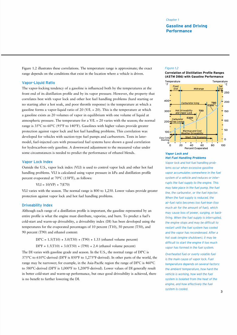
Various ranges of a distillation profile correlate with specific
aspects of gasoline performance.
Front-end volatility is adjusted to provide:
• Easy cold starting.
• Easy hot starting.
• Freedom from vapor lock or other hot fuel handling problems.
• Low evaporation and running-loss emissions.
Midrange volatility is adjusted to provide:
• Rapid warm-up and smooth running.
• Good short-trip fuel economy.
• Good power and acceleration.
• Protection against carburetor icing and hot-stalling.
Tail-end volatility is adjusted to provide:
• Good fuel economy after engine warm-up.
• Freedom from engine deposits.
• Minimal fuel dilution of crankcase oil.
• Minimal volatile organic compound (VOC) exhaust emissions(see page 17).
2
Vapor Pressure
For those materials that can exist as a
vapor, some vapor is present even
when the material is in its liquid or
solid state. A material’s vapor pressure
is the pressure exerted by the vapor
when the vapor is in equilibrium with
the liquid or solid. The vapor pressure
of gasoline is measured at a tempera-
ture of 37.8°C (100°F) and a pressure
of 1 atmosphere. Vapor pressure is
expressed as kilopascals (kPa) or
pounds per square inch (psi).
Figure 1.1
Typical Distillation Proles of Summer
and Winter Gasolines (ASTM D86)
190
220
160
130
100
70
40
10
0 10 20 30 40 50 60 70 80 90 100
Percent Evaporated Regular-Grade Unleaded: 2008 United States Averages
Winter Conventional GasolineVapor Pressure: 13.0 psi
Summer Conventional GasolineVapor Pressure: 7.9 psi
Summer Ethanol Reformulated GasolineVapor Pressure: 7.0 psi
450
350
250
150
400
300
200
100
50
0
Temperature°F
Temperature°C
8/9/2019 AAAAAAAA MotorGas Tech Review
http://slidepdf.com/reader/full/aaaaaaaa-motorgas-tech-review 11/124
Figure 1.2 illustrates these correlations. The temperature range is approximate; the exact
range depends on the conditions that exist in the location where a vehicle is driven.
Vapor-Liquid Ratio
The vapor-locking tendency of a gasoline is influenced both by the temperatures at the
front end of its distillation profile and by its vapor pressure. However, the property that
correlates best with vapor lock and other hot fuel handling problems (hard starting or
no starting after a hot soak, and poor throttle response) is the temperature at which a
gasoline forms a vapor-liquid ratio of 20 (V/L = 20). This is the temperature at which
a gasoline exists as 20 volumes of vapor in equilibrium with one volume of liquid at
atmospheric pressure. The temperature for a V/L = 20 varies with the season; the normal
range is 35°C to 60°C (95°F to 140°F). Gasolines with higher values provide greater
protection against vapor lock and hot fuel handling problems. This correlation was
developed for vehicles with suction-type fuel pumps and carburetors. Tests in later-
model, fuel-injected cars with pressurized fuel systems have shown a good correlation
for hydrocarbon-only gasoline. A downward adjustment to the measured value under
some circumstances is needed to predict the performance of ethanol blends.
Vapor Lock Index
Outside the U.S., vapor lock index (VLI) is used to control vapor lock and other hot fuel
handling problems. VLI is calculated using vapor pressure in kPa and distillation profile
percent evaporated at 70°C (158°F), as follows:
VLI = 10(VP) + 7(E70)
VLI varies with the season. The normal range is 800 to 1,250. Lower values provide greater
protection against vapor lock and hot fuel handling problems.
Driveability Index
Although each range of a distillation profile is important, the gasoline represented by an
entire profile is what the engine must distribute, vaporize, and burn. To predict a fuel’s
cold-start and warm-up driveability, a driveability index (DI) has been developed using the
temperatures for the evaporated percentages of 10 percent (T10), 50 percent (T50), and
90 percent (T90) and ethanol content:
DI°C = 1.5(T10) + 3.0(T50) + (T90) + 1.33 (ethanol volume percent)
DI°F = 1.5(T10) + 3.0(T50) + (T90) + 2.4 (ethanol volume percent)
The DI varies with gasoline grade and season. In the U.S., the normal range of DI°C is
375°C to 610°C-derived (DI°F is 850°F to 1,275°F-derived). In other parts of the world, the
range may be narrower; for example, in the Asia-Pacific region the range of DI°C is 460°C
to 580°C-derived (DI°F is 1,000°F to 1,200°F-derived). Lower values of DI generally result
in better cold-start and warm-up performance, but once good driveability is achieved, there
is no benefit to further lowering the DI.
3
Chapter 1
Gasoline and DrivingPerformance
Vapor Lock and
Hot Fuel Handling Problems
Vapor lock and hot fuel handling prob-
lems occur when excessive gasoline
vapor accumulates somewhere in the fuel
system of a vehicle and reduces or inter-
rupts the fuel supply to the engine. This
may take place in the fuel pump, the fuel
line, the carburetor, or the fuel injector.
When the fuel supply is reduced, the
air-fuel ratio becomes too fuel-lean (too
much air for the amount of fuel), which
may cause loss of power, surging, or back-
firing. When the fuel supply is interrupted,
the engine stops and may be difficult to
restart until the fuel system has cooled
and the vapor has recondensed. After a
hot soak (engine shutdown), it may be
difficult to start the engine if too much
vapor has formed in the fuel system.
Overheated fuel or overly volatile fuel
is the main cause of vapor lock. Fuel
temperature depends on several factors:
the ambient temperature, how hard the
vehicle is working, how well the fuel
system is isolated from the heat of the
engine, and how effectively the fuel
system is cooled.
Figure 1.2
Correlation of Distillation Prole Ranges
(ASTM D86) with Gasoline Performance
Hot Driveability and Vapor Lock
Carburetor Icing
FrontEnd
TailEnd Midrange
Carburetor Evap. Losses
Warmup and CoolWeather Driveability
Short Trip Economy
T90
T50
E300
E200
Easy Cold Starting
2
2
15
10
5
0
400
300
200
100
0
Percent Evaporated0 20 40 60 80 100
Temperature
°FTemperatur
°
8/9/2019 AAAAAAAA MotorGas Tech Review
http://slidepdf.com/reader/full/aaaaaaaa-motorgas-tech-review 12/124
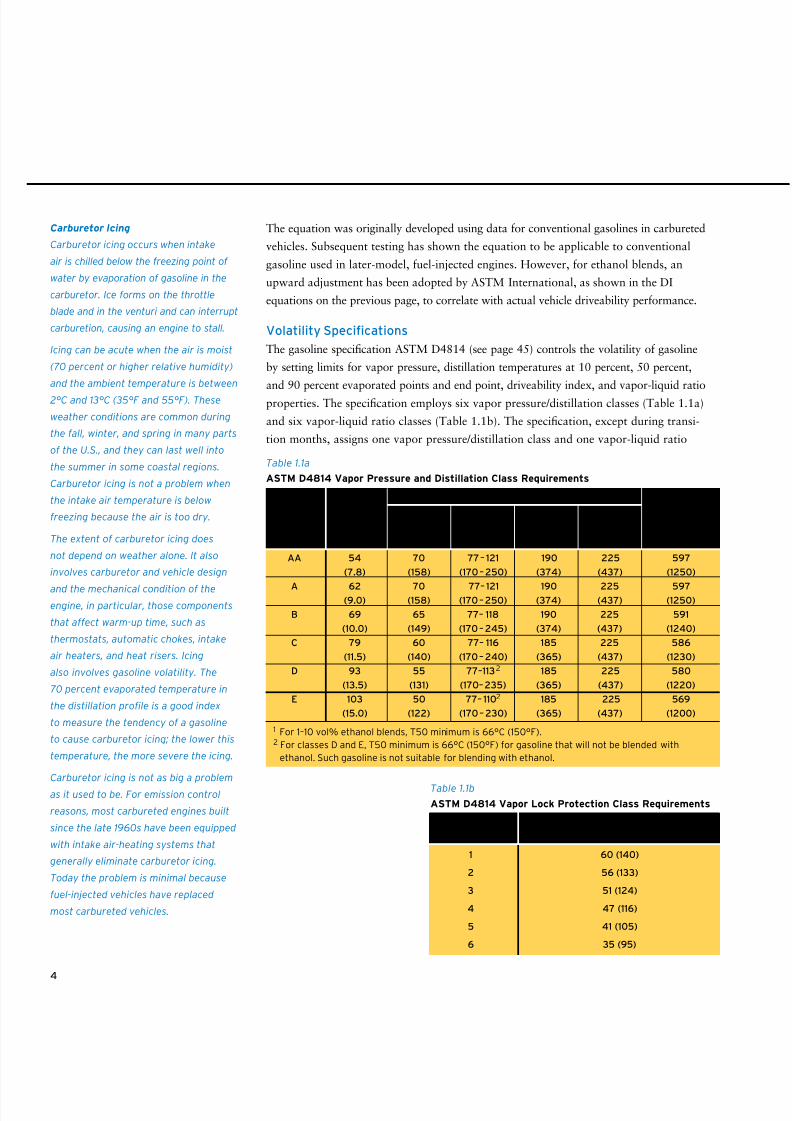
4
Carburetor Icing
Carburetor icing occurs when intake
air is chilled below the freezing point of
water by evaporation of gasoline in the
carburetor. Ice forms on the throttle
blade and in the venturi and can interrupt
carburetion, causing an engine to stall.
Icing can be acute when the air is moist
(70 percent or higher relative humidity)
and the ambient temperature is between
2°C and 13°C (35°F and 55°F). These
weather conditions are common during
the fall, winter, and spring in many parts
of the U.S., and they can last well into
the summer in some coastal regions.
Carburetor icing is not a problem when
the intake air temperature is below
freezing because the air is too dry.
The extent of carburetor icing does
not depend on weather alone. It also
involves carburetor and vehicle design
and the mechanical condition of theengine, in particular, those components
that affect warm-up time, such as
thermostats, automatic chokes, intake
air heaters, and heat risers. Icing
also involves gasoline volatility. The
70 percent evaporated temperature in
the distillation profile is a good index
to measure the tendency of a gasoline
to cause carburetor icing; the lower this
temperature, the more severe the icing.
Carburetor icing is not as big a problem
as it used to be. For emission control
reasons, most carbureted engines built
since the late 1960s have been equipped
with intake air-heating systems that
generally eliminate carburetor icing.
Today the problem is minimal because
fuel-injected vehicles have replaced
most carbureted vehicles.
Table 1.1b
ASTM D4814 Vapor Lock Protection Class Requirements
1 60 (140)
2 56 (133)
3 51 (124)
4 47 (116)
5 41 (105)
6 35 (95)
Vapor Lock Temperature, °C (°F) for aProtection Class Vapor-Liquid Ratio of 20, min
The equation was originally developed using data for conventional gasolines in carbureted
vehicles. Subsequent testing has shown the equation to be applicable to conventional
gasoline used in later-model, fuel-injected engines. However, for ethanol blends, an
upward adjustment has been adopted by ASTM International, as shown in the DI
equations on the previous page, to correlate with actual vehicle driveability performance.
Volatility Specifications
The gasoline specification ASTM D4814 (see page 45) controls the volatility of gasoline
by setting limits for vapor pressure, distillation temperatures at 10 percent, 50 percent,
and 90 percent evaporated points and end point, driveability index, and vapor-liquid ratio
properties. The specification employs six vapor pressure/distillation classes (Table 1.1a)
and six vapor-liquid ratio classes (Table 1.1b). The specification, except during transi-
tion months, assigns one vapor pressure/distillation class and one vapor-liquid ratio
Table 1.1a
ASTM D4814 Vapor Pressure and Distillation Class Requirements
AA 54 70 77– 121 190 225 597
(7.8) (158) (170–250) (374) (437) (1250)
A 62 70 77– 121 190 225 597(9.0) (158) (170–250) (374) (437) (1250)
B 69 65 77– 118 190 225 591
(10.0) (149) (170– 245) (374) (437) (1240)
C 79 60 77– 116 185 225 586
(11.5) (140) (170– 240) (365) (437) (1230)
D 93 55 77–1132 185 225 580
(13.5) (131) (170–235) (365) (437) (1220)
E 103 50 77– 1102 185 225 569
(15.0) (122) (170– 230) (365) (437) (1200)
10 vol% 50 vol% 90 vol%
Evap., Evap.,1 Evap., End Point,
max min — max max max
Vapor
Pressure/
Distillation
Class
Distillation Temperature, °C (°F) Driveability
Index,
max
Derived °C (°F)
Vapor
Pressure,
kPa (psi)
max
1 For 1–10 vol% ethanol blends, T50 minimum is 66°C (150°F).2 For classes D and E, T50 minimum is 66°C (150°F) for gasoline that will not be blended with
ethanol. Such gasoline is not suitable for blending with ethanol.
8/9/2019 AAAAAAAA MotorGas Tech Review
http://slidepdf.com/reader/full/aaaaaaaa-motorgas-tech-review 13/124
5
Chapter 1
Gasoline and DrivingPerformance
class each month to each geographical area (state or portion of a state) in the U.S. based
on altitude and the expected ambient temperature range.
Gasoline volatility affects not only a vehicle’s driveability but also its VOC emissions
(from evaporation and exhaust, see page 20). To help control the aspect of air quality
affected by hydrocarbon emissions, the U.S. government and some states limit gasoline
volatility by law. ASTM International incorporates volatility (vapor pressure) regulations
from the U.S. EPA and state implementation plans (SIPs) into its gasoline specifications as
such controls are promulgated and approved.
Fluctuating volatility requirements make gasoline manufacture and distribution a complex
process. A refiner producing gasoline for a multistate area may have to make gasolines
with several different volatilities and change the volatility from month to month. Each
gasoline must be shipped separately to the appropriate location.
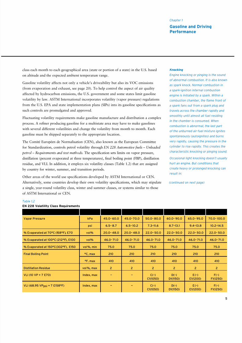
The Comité Européen de Normalisation (CEN), also known as the European Committee
for Standardization, controls petrol volatility through EN 228 Automotive fuels – Unleaded
petrol – Requirements and test methods. The specification sets limits on vapor pressure,
distillation (percent evaporated at three temperatures), final boiling point (FBP), distillation
residue, and VLI. In addition, it employs six volatility classes (Table 1.2) that are assigned
by country for winter, summer, and transition periods.
Other areas of the world use specifications developed by ASTM International or CEN.
Alternatively, some countries develop their own volatility specifications, which may stipulate
a single, year-round volatility class, winter and summer classes, or systems similar to those
of ASTM International or CEN.
Table 1.2
EN 228 Volatility Class Requirements
Volatility Unit Class A Class B Class C/C1 Class D/D1 Class E/E1 Class F/F1
Vapor Pressure kPa 45.0– 60.0 45.0–70.0 50.0– 80.0 60.0– 90.0 65.0– 95.0 70.0– 100.0
psi 6.5– 8.7 6.5– 10.2 7.3–11.6 8.7–13.1 9.4–13.8 10.2–14.5
% Evaporated at 70°C (158°F), E70 vol% 20.0– 48.0 20.0– 48.0 22.0– 50.0 22.0– 50.0 22.0– 50.0 22.0– 50.0
% Evaporated at 100°C (212°F), E100 vol% 46.0– 71.0 46.0– 71.0 46.0– 71.0 46.0– 71.0 46.0– 71.0 46.0– 71.0
% Evaporated at 150°C(302°F), E150 vol%, min 75.0 75.0 75.0 75.0 75.0 75.0
Final Boiling Point °C, max 210 210 210 210 210 210
°F, max 410 410 410 410 410 410
Distillation Residue vol%, max 2 2 2 2 2 2
VLI (10 VP + 7 E70) Index, max — — C(–) D(–) E(–) F(–)
C1(1050) D1(1150) E1(1200) F1(1250)
VLI (68.95 VPpsi + 7 E158°F) Index, max — — C(–) D(–) E(–) F(–)
C1(1050) D1(1150) E1(1200) F1(1250)
Knocking
Engine knocking or pinging is the sound
of abnormal combustion. It is also known
as spark knock. Normal combustion in
a spark-ignition internal combustion
engine is initiated by a spark. Within a
combustion chamber, the flame front of
a spark fans out from a spark plug and
travels across the chamber rapidly and
smoothly until almost all fuel residing
in the chamber is consumed. When
combustion is abnormal, the last part
of the unburned air-fuel mixture ignites
spontaneously (autoignites) and burns
very rapidly, causing the pressure in the
cylinder to rise rapidly. This creates the
characteristic knocking or pinging sound.
Occasional light knocking doesn’t usually
hurt an engine. But conditions that
create heavy or prolonged knocking can
result in:
(continued on next page)
8/9/2019 AAAAAAAA MotorGas Tech Review
http://slidepdf.com/reader/full/aaaaaaaa-motorgas-tech-review 14/124
6
• Objectionable noise
• Loss of power
• Overheating of engine parts
• Knock-induced surface ignition
• Engine damage
Knock occurs because the gasoline
burning in an engine has an antiknock
rating (octane number) below the anti-
knock requirement of the engine at thatmoment. Generally, the situation involves
high-load conditions, such as hard accel-
eration or climbing a grade.
Other Abnormal Combustion
Phenomena
Other abnormal combustion phenomena
can occur in addition to knocking.
Surface ignition involves the ignition of
the air-fuel mixture by a hot spot rather
than a spark. Potential ignition sources
include glowing combustion chamber
deposits, sharp edges or burrs in the
combustion chamber, and an overheated
spark plug electrode.
Heavy, prolonged spark knock can
generate hot spots that produce surface
ignition. A hot spot can ignite a portion
of the air-fuel mixture before the mixture
would normally start to burn. This may
occur either before or after spark igni-
tion. Surface ignition before a spark is
called preignition. Surface ignition after
a spark is called post-ignition. When
preignition occurs, ignition timing is lost
and upward movement of the piston is
opposed by the high pressure gener-
ated by early combustion. This results in
engine roughness, power loss, and severe
localized heating of the piston crown. If
it is prolonged, the localized heating can
burn a hole in the piston.
(continued on next page)
ANTIKNOCK PERFORMANCE
Knock-free engine performance is as important as good driveability. Octane number is
a measure of a gasoline’s antiknock performance, that is, a gasoline’s ability to resist
knocking as it burns in the combustion chamber. There are two laboratory test methods
used to measure the octane number of a gasoline (see page 47). One method yields the
Research octane number (RON ); the other results in the Motor octane number (MON ).
RON correlates best low-speed, mild-knocking conditions; MON correlates best high-
speed and high-temperature knocking conditions and with part-throttle operation. For
a given gasoline, RON is always greater than MON. The difference between the two
indicates the sensitivity of the gasoline to changes in operating conditions. The larger the
difference, the more sensitive the gasoline.
RON and MON are measured in a single-cylinder laboratory engine, so they do not
completely predict antiknock performance in multicylinder engines. The Modified
Uniontown procedure (see page 48) involves using an actual vehicle to measure the
antiknock performance of a gasoline. The resulting value is called Road octane number
(RdON ). Because vehicle testing is more complex than laboratory testing, there have
been several attempts to predict RdON from RON and MON. The equations take the
following form:
RdON = a(RON) + b(MON) + c
A good approximation for RdON is a = b = 0.5 and c = 0, yielding (RON + MON)/2,
commonly written (R + M)/2. This is called the antiknock index (AKI ). The U.S. Federal
Trade Commission requires dispensing pumps to be labeled (posted) with the AKI of
the gasoline they dispense.1 In addition, owner’s manuals for vehicles in the U.S. must
specify recommended fuel by AKI.2 (R + M)/2 is voluntarily posted in Canada.
Neither the AKI nor any of the other single-value indices that have been developed
forecast the performance of a gasoline in all vehicles. In some vehicles, performance
correlates better with either RON or MON alone rather than with a combination of
the two. Also, for a given vehicle, the correlation can vary with driving conditions.3
As the formula indicates, gasolines with the same AKI can have different RONs and
MONs. This may explain why a vehicle knocks while running on certain brands of
gasoline or even between fill-ups of the same brand. Of course, for a comparison to be
valid, a vehicle must be operated under identical conditions, which is not easy for the
typical driver to arrange.
1 The gasoline being dispensed must have an antiknock index equal to or greater than the posted value.Rounding the number upward is not permitted.
2 Older owner’s manuals of some foreign cars specify RON; some more recent ones specify both RONand AKI.
3 See Table 1.3 on page 8 for the variables that affect an engine’s octane number requirement.
(continued from previous page)
8/9/2019 AAAAAAAA MotorGas Tech Review
http://slidepdf.com/reader/full/aaaaaaaa-motorgas-tech-review 15/124
Generally, three grades of unleaded gasoline with different AKIs are available in the U.S.:
regular, midgrade, and premium. At sea level, the posted AKI for regular grade is usually 87;
for midgrade, 89. The AKI of premium grade varies, ranging from 91 to 94.
The posted AKIs are lower in the Rocky Mountain states. Altitude gasolines have histori-
cally provided the same antiknock performance as higher-AKI gasolines at sea level. The
octane requirement of older-model engines decreases as air pressure (barometric pressure)
decreases. Barometric pressure is lower at higher elevations.
Since 1984, vehicles have been equipped with more sophisticated control systems,
including sensors to measure and engine management computers to adjust for changes
in air temperature and barometric pressure (see page 69). These vehicles are designed to
have the same AKI requirement at all elevations, and the owner’s manuals specify the
same AKI gasoline at all elevations.
Outside the U.S. and Canada, when an octane number is posted at a service station, RON
is generally used. In these countries, vehicle owner’s manuals also specify the minimum
octane grade recommended in terms of RON.
It is difficult for a driver to know whether a gasoline has the antiknock performance an
engine requires when the engine is equipped with a knock sensor system. These systems,
which temporarily retard spark timing to eliminate knocking, are installed on many late-
model engines (see page 72). Retarding the spark reduces power and acceleration. The
knock sensor responds so quickly that the driver never notices the knock. Loss of power
and acceleration will be the only clue that the antiknock quality of the gasoline does not
meet the vehicle’s octane requirement.
Using gasoline with an antiknock rating higher than that required to prevent knock or to
prevent spark retardation by the knock sensor will not improve a vehicle’s performance.
OCTANE NUMBER REQUIREMENT
The technical octane number requirement (ONR) of an engine is the octane number
of a reference fuel that will produce trace knock under the most severe speed and load
conditions. Trace knock is the knock intensity that is just audible to a trained technician.
Customers may or may not be able to detect trace knock, so customer ONR is usually lessthan the technical ONR. For the remainder of this review, ONR will refer to technical
ONR. ONR can be reported as a RON or AKI value.
The ONR of an engine is usually determined for either maximum-throttle or part-throttle
acceleration conditions, whichever is the most critical. ONR varies considerably engine to
engine, sometimes as much as 10 points among vehicles with the same engine model.
Chapter 1
Gasoline and DrivingPerformance
7
When preignition is caused by a hot spot
generated by prolonged, heavy spark
knock, it is known as knock-induced
preignition. It has the same adverse
effect on engine operation as preigni-
tion from other sources. Knock-induced
preignition is the most damaging side
effect of spark knock.
Post-ignition reduces combustion time,and loss of combustion control can cause
knock, engine roughness, and reduced
power output. The extent of the effect of
post-ignition depends on its location in a
combustion chamber and the time in the
combustion cycle that it occurs.
Run-on occurs when the engine continues
to run after a vehicle’s ignition switch
is turned off. It also is referred to as
after-running or dieseling. The engine
runs noisily, and the exhaust smells bad.
Run-on usually is caused by compression-
ignition, when a combustion chamber
is hot enough to autoignite the air-fuel
mixture; however, it also can be caused
by surface ignition. The incidence of
run-on is decreased or eliminated as the
octane quality, especially the RON, of a
gasoline is increased. Another important
run-on factor is idle speed. This is why
many carbureted engines are equipped
with an idle stop (anti-dieseling) solenoid.
Run-on is not a problem with modernfuel-injected engines because fuel cannot
be delivered to combustion chambers
when the ignition switch is turned off.
(continued from previous page)
8/9/2019 AAAAAAAA MotorGas Tech Review
http://slidepdf.com/reader/full/aaaaaaaa-motorgas-tech-review 16/124
8
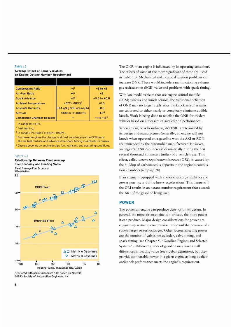
The ONR of an engine is influenced by its operating conditions.
The effects of some of the more significant of these are listed
in Table 1.3. Mechanical and electrical ignition problems can
increase ONR. These would include a malfunctioning exhaust
gas recirculation (EGR) valve and problems with spark timing.
With late-model vehicles that use engine control module
(ECM) systems and knock sensors, the traditional definition
of ONR may no longer apply since the knock sensor systems
are calibrated to either nearly or completely eliminate audible
knock. Work is being done to redefine the ONR for modern
vehicles based on a measure of acceleration performance.
When an engine is brand-new, its ONR is determined by
its design and manufacture. Generally, an engine will not
knock when operated on a gasoline with the AKI or RON
recommended by the automobile manufacturer. However,
an engine’s ONR can increase dramatically during the first
several thousand kilometers (miles) of a vehicle’s use. This
effect, called octane requirement increase (ORI ), is caused by
the buildup of carbonaceous deposits in the engine’s combus-
tion chambers (see page 78).If an engine is equipped with a knock sensor, a slight loss of
power may occur during heavy accelerations. This happens if
the ORI results in an octane number requirement that exceeds
the AKI of the gasoline being used.
POWER
The power an engine can produce depends on its design. In
general, the more air an engine can process, the more power
it can produce. Major design considerations for power are
engine displacement, compression ratio, and the presence of a
supercharger or turbocharger. Other factors affecting power
are the number of valves per cylinder, valve timing, and
spark timing (see Chapter 5, “Gasoline Engines and Selected
Systems”). Different grades of gasoline may have small
differences in heating value (see sidebar definition), but they
provide comparable power in a given engine as long as their
antiknock performance meets the engine’s requirement.
1 In range 8:1 to 11:1.
2 Fuel leaning.
3 In range 71°C (160°F) to 82°C (180°F).
4 For newer engines the change is almost zero because the ECM leans
the air-fuel mixture and advances the spark timing as altitude increases.
5 Change depends on engine design, fuel, lubricant, and operating conditions.
Change in ONR,Variable Change in Variable (AKI Number)
Compression Ratio +11 +3 to +5
Air-Fuel Ratio +12 +2
Spark Advance +1° +0.5 to +0.8
Ambient Temperature +6°C (+10°F)3 +0.5
Absolute Humidity +1.4 g/kg (+10 grains/lb) –0.3
Altitude +300 m (+1,000 ft) – 1.5
4
Combustion Chamber Deposits — +1 to +135
Table 1.3
Average Effect of Some Variables
on Engine Octane Number Requirement
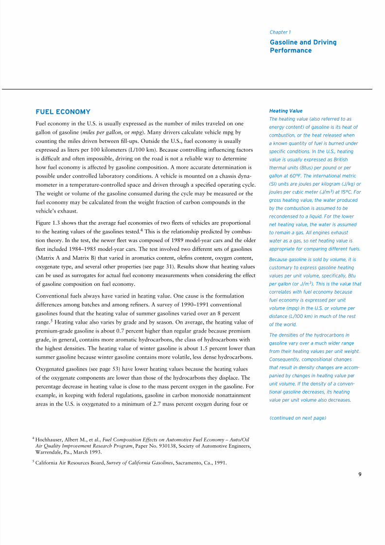
Figure 1.3
Relationship Between Fleet Average
Fuel Economy and Heating Value
Reprinted with permission from SAE Paper No. 930138
©1993 Society of Automotive Engineers, Inc.
Heating Value, Thousands Btu/Gallon
17
18
19
20
21
22
Fleet Average Fuel Economy,
Miles/Gallon
108 110 112 114 116 118
1989 Fleet
1984–85 Fleet
Matrix A Gasolines
Matrix B Gasolines
8/9/2019 AAAAAAAA MotorGas Tech Review
http://slidepdf.com/reader/full/aaaaaaaa-motorgas-tech-review 17/124
9
Chapter 1
Gasoline and DrivingPerformance
FUEL ECONOMY
Fuel economy in the U.S. is usually expressed as the number of miles traveled on one
gallon of gasoline (miles per gallon, or mpg ). Many drivers calculate vehicle mpg by
counting the miles driven between fill-ups. Outside the U.S., fuel economy is usually
expressed as liters per 100 kilometers (L/100 km). Because controlling influencing factors
is difficult and often impossible, driving on the road is not a reliable way to determine
how fuel economy is affected by gasoline composition. A more accurate determination is
possible under controlled laboratory conditions. A vehicle is mounted on a chassis dyna-
mometer in a temperature-controlled space and driven through a specified operating cycle.
The weight or volume of the gasoline consumed during the cycle may be measured or the
fuel economy may be calculated from the weight fraction of carbon compounds in the
vehicle’s exhaust.
Figure 1.3 shows that the average fuel economies of two fleets of vehicles are proportional
to the heating values of the gasolines tested.4 This is the relationship predicted by combus-
tion theory. In the test, the newer fleet was composed of 1989 model-year cars and the older
fleet included 1984–1985 model-year cars. The test involved two different sets of gasolines
(Matrix A and Matrix B) that varied in aromatics content, olefins content, oxygen content,
oxygenate type, and several other properties (see page 31). Results show that heating values
can be used as surrogates for actual fuel economy measurements when considering the effect
of gasoline composition on fuel economy.
Conventional fuels always have varied in heating value. One cause is the formulation
differences among batches and among refiners. A survey of 1990–1991 conventional
gasolines found that the heating value of summer gasolines varied over an 8 percent
range.5 Heating value also varies by grade and by season. On average, the heating value of
premium-grade gasoline is about 0.7 percent higher than regular grade because premium
grade, in general, contains more aromatic hydrocarbons, the class of hydrocarbons with
the highest densities. The heating value of winter gasoline is about 1.5 percent lower than
summer gasoline because winter gasoline contains more volatile, less dense hydrocarbons.
Oxygenated gasolines (see page 53) have lower heating values because the heating values
of the oxygenate components are lower than those of the hydrocarbons they displace. The
percentage decrease in heating value is close to the mass percent oxygen in the gasoline. For
example, in keeping with federal regulations, gasoline in carbon monoxide nonattainment
areas in the U.S. is oxygenated to a minimum of 2.7 mass percent oxygen during four or
4 Hochhauser, Albert M., et al., Fuel Composition Effects on Automotive Fuel Economy – Auto/OilAir Quality Improvement Research Program, Paper No. 930138, Society of Automotive Engineers,Warrendale, Pa., March 1993.
5 California Air Resources Board, Survey of California Gasolines, Sacramento, Ca., 1991.
Heating Value
The heating value (also referred to as
energy content) of gasoline is its heat of
combustion, or the heat released when
a known quantity of fuel is burned under
specific conditions. In the U.S., heating
value is usually expressed as British
thermal units (Btus) per pound or per
gallon at 60°F. The international metric
(SI) units are joules per kilogram (J/kg) or
joules per cubic meter (J/m 3 ) at 15°C. For
gross heating value, the water produced
by the combustion is assumed to be
recondensed to a liquid. For the lower
net heating value, the water is assumed
to remain a gas. All engines exhaust
water as a gas, so net heating value is
appropriate for comparing different fuels.
Because gasoline is sold by volume, it is
customary to express gasoline heating
values per unit volume, specifically, Btu
per gallon (or J/m
3
). This is the value thatcorrelates with fuel economy because
fuel economy is expressed per unit
volume (mpg) in the U.S. or volume per
distance (L/100 km) in much of the rest
of the world.
The densities of the hydrocarbons in
gasoline vary over a much wider range
from their heating values per unit weight.
Consequently, compositional changes
that result in density changes are accom-
panied by changes in heating value per
unit volume. If the density of a conven-
tional gasoline decreases, its heating
value per unit volume also decreases.
(continued on next page)
8/9/2019 AAAAAAAA MotorGas Tech Review
http://slidepdf.com/reader/full/aaaaaaaa-motorgas-tech-review 18/124
10
five winter months.6 The heating value of the oxygenated product is about 2.7 mass percent
lower than that of conventional gasoline. In addition, federal RFG and California Phase 3 RFG
in federal RFG areas are typically oxygenated year-round to an average oxygen content of
about 2 mass percent. The resulting heating values are about 2 percent lower than that of
conventional gasoline. California Phase 3 RFG also has limits on distillation temperatures
and aromatics content, which has the secondary effect of lowering the density of the fuel.
These limits reduce heating value by about another 1 percent.
The gasolines that produced the results displayed in Figure 1.3 were specially formulated
to span a wide range of compositions. The compositional variations were much greater
than those separating conventional and reformulated commercial gasolines. Thus, the
results provide solid evidence that RFG does not exert an unusual effect on fuel economy.
Individual drivers have reported decreases of 10 percent, 15 percent, and even 20 percent
in fuel economy when they began using RFG. Not surprisingly, many of the claims are
anecdotal. Most drivers do not keep continuous fuel-economy records, so they don’t have
a meaningful fuel-economy baseline for the gasoline they previously used. Even with a
baseline, a fuel-economy value based on the consumption of a single tank of gasoline can
be misleading. Drivers interested in fuel economy should average results over several tanks
of gasoline or, better yet, over several months of driving.
Factors Affecting Fuel Economy
Fuel economy is affected by a vehicle’s size, weight, aerodynamics, fuel delivery system,engine design, and transmission type. These factors remain constant for a specific vehicle.
There are, however, many variable factors that influence fuel economy. As mentioned,
the heating value of gasoline is one. Weather conditions, air conditioner use, road condi-
tions, the route driven, traffic, driving speed, and driving style are others. Fuel economy
is also affected by the mechanical condition of the car, including the engine tune, wheel
alignment, and tire pressure. Some of these non-gasoline factors have the potential to
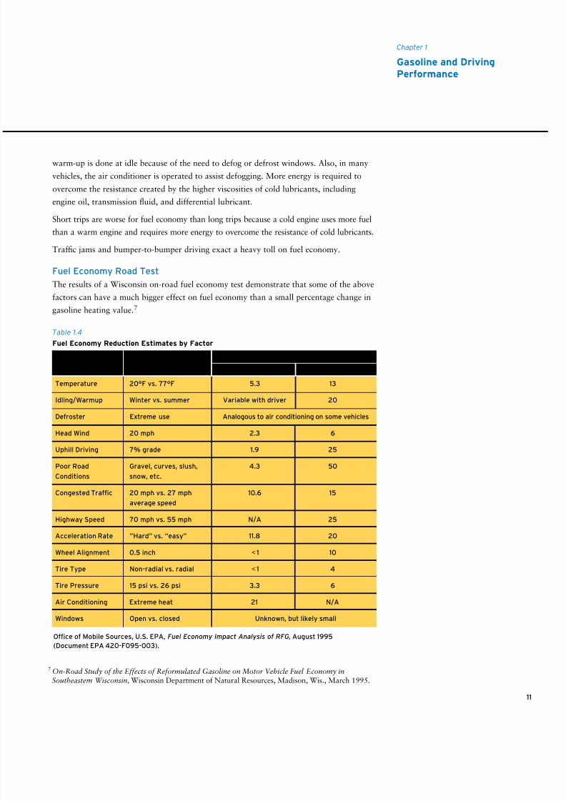
cause substantial changes in fuel economy. Table 1.4 lists average and maximum effects
published by the U.S. Environmental Protection Agency (EPA).
Carbonaceous engine deposits can build up over time and degrade fuel economy and
other performance attributes, but these problems can be reduced with the use of depositcontrol additives. This subject is discussed in detail in Chapter 6, “Gasoline Vehicles –
Deposit Control.”
Winter-related factors can combine to lower fuel economy up to 20 percent compared to
summer factors. These include rain or snow on the road, which increases tire resistance.
In addition, for safety a driver may need to slow down to a less fuel-efficient speed. In cold
weather, a richer air-fuel mixture is required to start and warm up an engine. Much of the
Adding oxygenates to conventional
gasoline also decreases heating value.
Oxygenates have lower heating values
than hydrocarbons on both unit-weight
and unit-volume bases. The amount of
decrease depends on the amounts and
identities of the oxygenates.
(continued from previous page)
6 Nonattainment area is a U.S. EPA designation for an area where an air pollutant, carbon monoxide
in this case, exceeds the limit established by the National Ambient Air Quality Standards more oftenthan allowed.
8/9/2019 AAAAAAAA MotorGas Tech Review
http://slidepdf.com/reader/full/aaaaaaaa-motorgas-tech-review 19/124
11
Chapter 1
Gasoline and DrivingPerformance
7 On-Road Study of the Effects of Reformulated Gasoline on Motor Vehicle Fuel Economy inSoutheastern Wisconsin, Wisconsin Department of Natural Resources, Madison, Wis., March 1995.
warm-up is done at idle because of the need to defog or defrost windows. Also, in many
vehicles, the air conditioner is operated to assist defogging. More energy is required to
overcome the resistance created by the higher viscosities of cold lubricants, including
engine oil, transmission fluid, and differential lubricant.
Short trips are worse for fuel economy than long trips because a cold engine uses more fuel
than a warm engine and requires more energy to overcome the resistance of cold lubricants.
Traffic jams and bumper-to-bumper driving exact a heavy toll on fuel economy.
Fuel Economy Road Test
The results of a Wisconsin on-road fuel economy test demonstrate that some of the above
factors can have a much bigger effect on fuel economy than a small percentage change in
gasoline heating value.7
Table 1.4
Fuel Economy Reduction Estimates by Factor
Temperature 20°F vs. 77°F 5.3 13
Idling/Warmup Winter vs. summer Variable with driver 20
Defroster Extreme use Analogous to air conditioning on some vehicles
Head Wind 20 mph 2.3 6
Uphill Driving 7% grade 1.9 25
Poor Road Gravel, curves, slush, 4.3 50
Conditions snow, etc.
Congested Traffic 20 mph vs. 27 mph 10.6 15
average speed
Highway Speed 70 mph vs. 55 mph N/A 25
Acceleration Rate ”Hard” vs. “easy” 11.8 20
Wheel Alignment 0.5 inch <1 10
Tire Type Non-radial vs. radial <1 4
Tire Pressure 15 psi vs. 26 psi 3.3 6
Air Conditioning Extreme heat 21 N/A
Windows Open vs. closed Unknown, but likely small
Factor Conditions Average Maximum
Percent Reduction in Fuel Economy
Office of Mobile Sources, U.S. EPA, Fuel Economy Impact Analysis of RFG, August 1995
(Document EPA 420-F095-003).
8/9/2019 AAAAAAAA MotorGas Tech Review
http://slidepdf.com/reader/full/aaaaaaaa-motorgas-tech-review 20/124
The test was designed to minimize all factors affecting fuel economy except gasoline
composition. Fueled with various gasolines, vehicles were driven over the same route
of 100 miles (161 kilometers) of urban and suburban roads. The fuel economy of each
vehicle was measured four times for each gasoline: once in the morning and afternoon
of the same day and again in the morning and afternoon of one day a week later. In
some cases, a vehicle was driven by the same driver both days. Other vehicles were
driven by more than one driver. When the results for the two weeks were compared,
most of the fuel economies in the second week were lower. The differences were greater
than 10 percent for a quarter of the car-fuel combinations. Two factors that probably
contributed to the week-to-week differences were driver changes and a weather change.Ambient temperatures were lower in the second week; on some days, noontime temper-
atures were as much as 17°C (30°F) cooler than the average noontime temperature of
the preceding week.
The gasolines used in the Wisconsin test were commercial gasolines, either a conventional
gasoline or a federal RFG oxygenated with methyl tertiary butyl ether (MTBE), ethyl
tertiary butyl ether (ETBE), or ethanol (EtOH). When the results for all the road tests
of all the vehicles were combined, the average fuel economy of the three oxygenated
federal RFGs was 2.8 percent lower than the average fuel economy of the conventional
gasoline. This value was much less than the 10 percent week-to-week difference for
some of the car-fuel combinations but within the range predicted by the differences in
the gasolines’ heating values.
OTHER PERFORMANCE FACTORS
Many gasolines available around the world contain oxygenates. In engines without
closed-loop feedback systems, oxygenated gasoline leans the air-fuel mixture. Fuel
leaning can cause some degradation in driveability, depending on an engine’s calibration
(see page 57).
Without fuel additives, deposits form throughout an engine’s intake system, including
in the fuel injectors, carburetor, intake manifold, and intake ports and on the intake
valves. Deposits can be very deleterious to engine performance, degrading driveability,
decreasing power and fuel economy, and increasing emissions.
12
8/9/2019 AAAAAAAA MotorGas Tech Review
http://slidepdf.com/reader/full/aaaaaaaa-motorgas-tech-review 21/124
13
2 • Gasoline and Air Quality
Today, we commonly discuss gasoline or gasoline-powered
vehicles and their impact on air quality. A number of metro-
politan areas in the U.S. fail to meet one or more federal air
quality standards. In some of these areas, on-road vehicles
are responsible for more than half of the emissions that either
primarily or secondarily cause violations of air quality stan-
dards. Other major metropolitan areas throughout the world
also are experiencing serious air pollution problems.
This chapter explains who regulates emissions and how and
why they do it. It also explains which emissions come from
vehicles and how those emissions are formed. Finally, it
explains how emissions are affected by gasoline characteristics
and how gasoline is being reformulated to help reduce emissions.
The explanations are complicated because they involve
complex regulations and complex science. As a consequence,
keeping this review short and simple is challenging. The
numerous acronyms and abbreviations are unavoidable; both
government regulation and science use them heavily.
PROGRESS IN THE UNITED STATES
Are the efforts of adding pollution control systems to vehicles
and reformulating gasoline paying off in better air quality?
The answer is yes. Urban air quality has improved dramati-
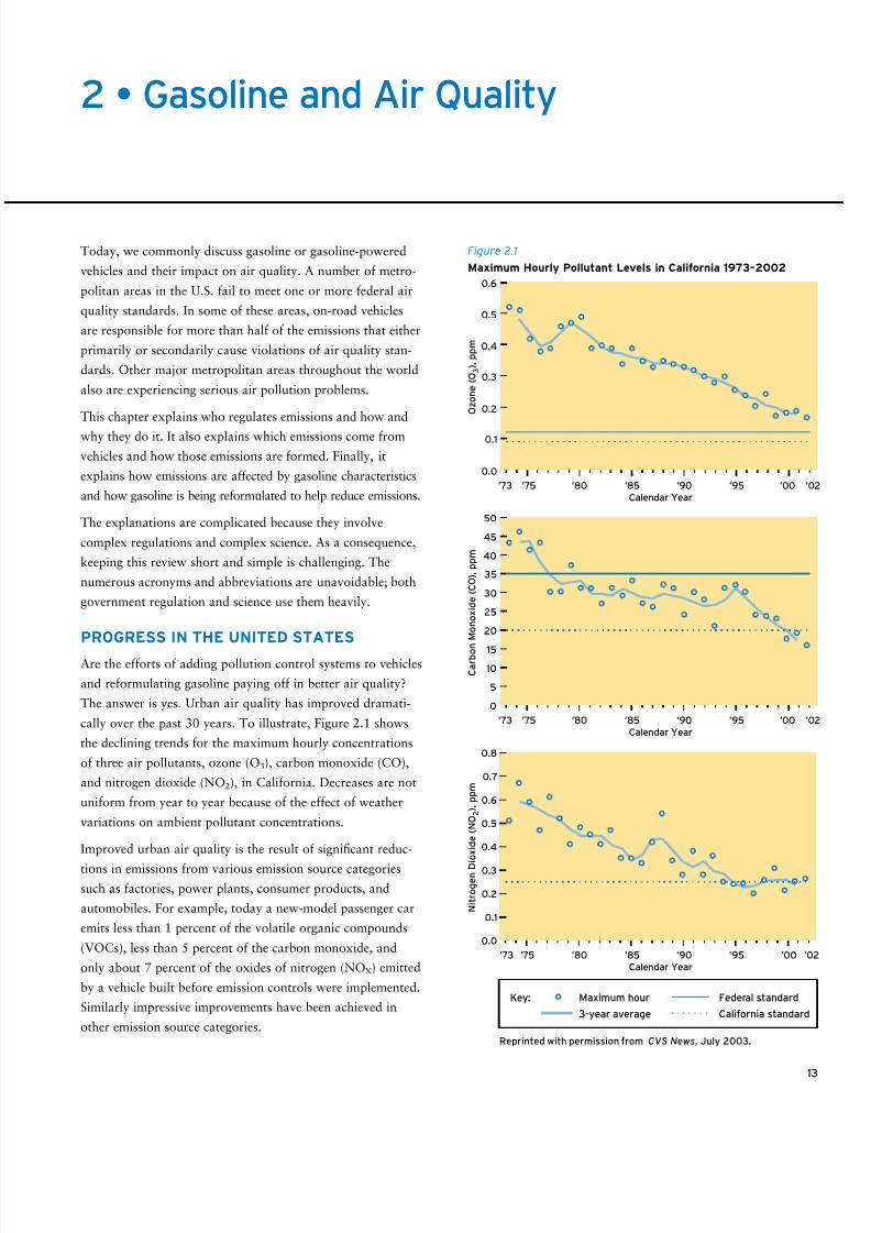
cally over the past 30 years. To illustrate, Figure 2.1 shows
the declining trends for the maximum hourly concentrations
of three air pollutants, ozone (O3), carbon monoxide (CO),
and nitrogen dioxide (NO2), in California. Decreases are not
uniform from year to year because of the effect of weather
variations on ambient pollutant concentrations.
Improved urban air quality is the result of significant reduc-
tions in emissions from various emission source categories
such as factories, power plants, consumer products, and
automobiles. For example, today a new-model passenger car
emits less than 1 percent of the volatile organic compounds
(VOCs), less than 5 percent of the carbon monoxide, and
only about 7 percent of the oxides of nitrogen (NOX) emitted
by a vehicle built before emission controls were implemented.
Similarly impressive improvements have been achieved in
other emission source categories.
’73 ’75 ’80 ’85 ’90 ’95 ’00 ’02
Calendar Year
’73 ’75 ’80 ’85 ’90 ’95 ’00 ’02
Calendar Year
’73 ’75 ’80 ’85 ’90 ’95 ’00 ’02
Calendar Year
0.6
0.5
0.4
0.3
0.2
0.1
0.0
O z o n e ( O 3 ) , p p m
50
45
40
35
30
25
20
15
10
5
0
C a r b o n
M o n o x i d e ( C O ) , p p m
0.8
0.5
0.4
0.7
0.6
0.3
0.2
0.1
0.0
N i t r o g e n D i o x i d e ( N O 2 ) , p p m
California standard
Maximum hour
3-year average
Federal standardKey:
Reprinted with permission from CVS News, July 2003.
Figure 2.1
Maximum Hourly Pollutant Levels in California 1973–2002
8/9/2019 AAAAAAAA MotorGas Tech Review
http://slidepdf.com/reader/full/aaaaaaaa-motorgas-tech-review 22/124
14
1 “History of the Clean Air Act,” U.S. EPA, http://epa.gov/air/caa/caa_history.html.
The introduction of reformulated gasolines (RFG) also has helped improve air quality.
Federal Phase I RFG was introduced in January 1995, Phase II in January 2000.
California Phase 2 RFG was required in California in mid-1996, and Phase 3 was required
at the end of 2003. Federal Phase II and California Phase 2 and Phase 3 reformulated
gasolines are believed to reduce ozone-forming emissions from cars and light trucks by
10 percent to 15 percent. This effect is not apparent in Figure 2.1 because of the year-to-
year variability caused by factors such as weather.
LEGISLATION
In the United States, federal legislation regarding air pollution began with the AirPollution Control Act of 1955. Air pollution control legislation was initiated with the
Clean Air Act of 1963 and expanded under the Air Quality Act of 1967 and the Clean
Air Act of 1970. The 1970 act was amended in 1977 and most recently in 1990. 1
Designed to manage the nation’s air quality and to advance regional air pollution preven-
tion and control programs, the act is wide-ranging, addressing a variety of air pollution
issues. However, in the area of vehicle emissions, it is restrictive, forbidding states from
setting separate vehicle emissions standards. This restriction was included so that auto
manufacturers would not have to produce cars with different emission control systems to
meet different state standards. The restriction was waived for California. With its more
severe smog levels and its long history of working to control vehicle emissions, California
is allowed to establish its own regulations for controlling vehicle emissions, subject to
federal approval. Under certain circumstances, other states are allowed to require the sale
of new vehicles that meet the more stringent California standards.
ADMINISTRATION/REGULATION
Laws are not administered by the body that adopts them. The U.S. Congress or state legisla-
ture assigns the administrative responsibility to a governmental agency. In 1970, the National
Environmental Policy Act created the U.S. Environmental Protection Agency (EPA) and made
it responsible for implementing the requirements of the federal Clean Air Act and its amend-
ments. California’s laws covering vehicle emissions are administered by the California Air
Resources Board (CARB), which was established by the state legislature in 1967.
While some laws contain a lot of detail, they can’t address all the issues surrounding their
application in our complex industrial society. The agency administering the law has the
responsibility to write regulations that will make the legislative intent a reality. Title 40
of the Code of Federal Regulations (CFR) contains U.S. EPA regulations concerning the
protection of the environment.
The states, as Congress intended, do much of the work to carry out the provisions of the
federal Clean Air Act and its amendments. State and local air pollution agencies hold
hearings, write regulations (based on guidance from the U.S. EPA), issue permits, monitor
The Beginning
Smog is the common term for the
forms of air pollution involving haze
and oxidants, such as ozone. Smog
was identified as a serious problem in
the Los Angeles basin in the 1950s.
As university scientists and govern-
ment health agencies investigated the
problem, they found that vehicle emis-
sions were a significant source of smog
precursors. Acting on this information,
the California legislature established
emissions limits for 1966-model cars.
Federal legislation to reduce vehicular
emissions, as part of a greater air
quality program, was initiated with the
adoption of the Clean Air Act of 1963.
The first federal limits for exhaust
emissions from gasoline-powered cars
were implemented starting with the
1968 model year.
8/9/2019 AAAAAAAA MotorGas Tech Review
http://slidepdf.com/reader/full/aaaaaaaa-motorgas-tech-review 23/124
pollution, issue notices of violations, and levy fines. It is appropriate for the states to take
the lead because state and local agencies need to select and enforce pollution control strategies
that make sense for their region. Geography, weather conditions, housing patterns, regional
traffic patterns, and the nature of local industry all influence pollution levels.2
The Clean Air Act and its amendments specify deadlines for the U.S. EPA, states, local
governments, and businesses to reduce air pollution. Each state is required to develop a
plan that explains the actions it will take to meet or maintain the air quality standards
set by the U.S. EPA. A state implementation plan (SIP) is a collection of the regulations a
state will use. The U.S. EPA must approve each state’s SIP. The U.S. EPA assists the states
by providing scientific research, expert studies, engineering designs, and money to support
clean-air programs.
AIR QUALITY STANDARDS
Air pollutants are natural and artificial airborne substances that may be introduced into
the environment in a sufficient concentration to have a measurable effect on humans,
animals, vegetation, or building materials. From a regulatory standpoint, substances
become air pollutants when the
U.S. EPA determines them to be.
As part of the process, the Clean Air
Act requires the U.S. EPA to issue
a criteria document that provides
details on the adverse effects of
individual pollutants. Regulated
pollutants therefore are referred to
as criteria pollutants. The U.S. EPA
uses the information in the criteria
documents to set National Ambient
Air Quality Standards (NAAQS) at
levels that protect the public health
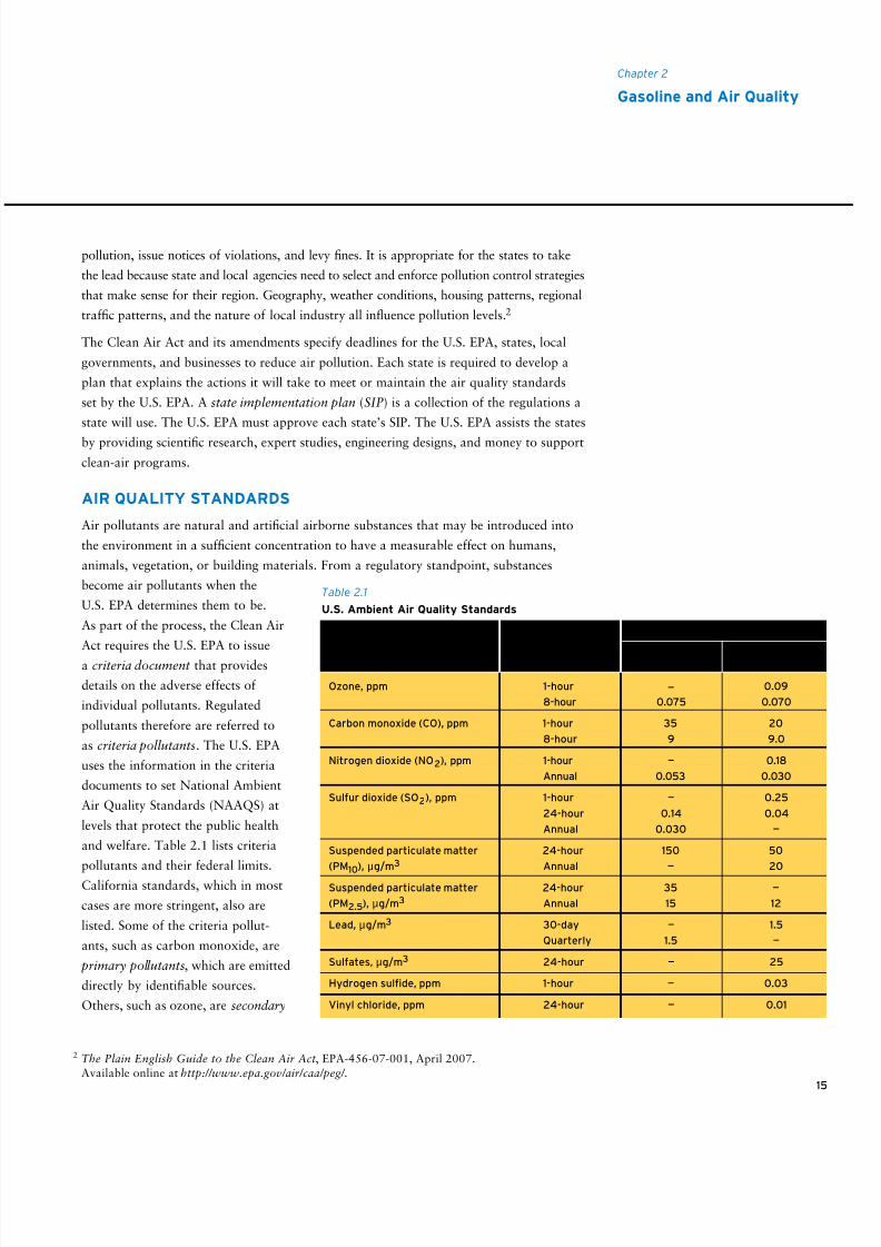
and welfare. Table 2.1 lists criteria
pollutants and their federal limits.
California standards, which in most
cases are more stringent, also are
listed. Some of the criteria pollut-
ants, such as carbon monoxide, are
primary pollutants, which are emitted
directly by identifiable sources.
Others, such as ozone, are secondary
15
Chapter 2
Gasoline and Air Quality
Ozone, ppm 1-hour — 0.09
8-hour 0.075 0.070
Carbon monoxide (CO), ppm 1-hour 35 20
8-hour 9 9.0
Nitrogen dioxide (NO2), ppm 1-hour — 0.18
Annual 0.053 0.030
Sulfur dioxide (SO2), ppm 1-hour — 0.25
24-hour 0.14 0.04
Annual 0.030 —
Suspended particulate matter 24-hour 150 50
(PM10
), µg/m3 Annual — 20
Suspended particulate matter 24-hour 35 —
(PM2.5), µg/m3 Annual 15 12
Lead, µg/m3 30-day — 1.5
Quarterly 1.5 —
Sulfates, µg/m3 24-hour — 25
Hydrogen sulfide, ppm 1-hour — 0.03
Vinyl chloride, ppm 24-hour — 0.01
Table 2.1
U.S. Ambient Air Quality Standards
Maximum Average Concentration
Averaging Federal California Criteria Pollutant Time Standard Standard
2 The Plain English Guide to the Clean Air Act , EPA-456-07-001, April 2007.
Available online at http://www.epa.gov/air/caa/peg/.
8/9/2019 AAAAAAAA MotorGas Tech Review
http://slidepdf.com/reader/full/aaaaaaaa-motorgas-tech-review 24/124
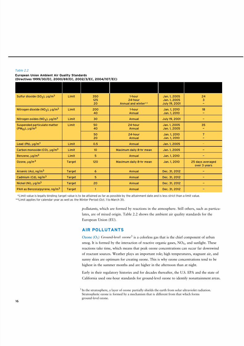
16
pollutants, which are formed by reactions in the atmosphere. Still others, such as particu-
lates, are of mixed origin. Table 2.2 shows the ambient air quality standards for the
European Union (EU).
AIR POLLUTANTS
Ozone (O3) Ground-level ozone3 is a colorless gas that is the chief component of urban
smog. It is formed by the interaction of reactive organic gases, NOX, and sunlight. These
reactions take time, which means that peak ozone concentrations can occur far downwind
of reactant sources. Weather plays an important role; high temperatures, stagnant air, and
sunny skies are optimum for creating ozone. This is why ozone concentrations tend to be
highest in the summer months and are higher in the afternoon than at night.
Early in their regulatory histories and for decades thereafter, the U.S. EPA and the state of
California used one-hour standards for ground-level ozone to identify nonattainment areas.
3 In the stratosphere, a layer of ozone partially shields the earth from solar ultraviolet radiation.
Stratospheric ozone is formed by a mechanism that is different from that which forms
ground-level ozone.
Table 2.2
European Union Ambient Air Quality Standards
(Directives 1999/30/EC, 2000/69/EC, 2002/3/EC, 2004/107/EC)
Legal Concentration, Permitted ExceedencesPollutant Nature* max Averaging Period Effective Date Each Years
Sulfur dioxide (SO2), µg/m3 Limit 350 1-hour Jan. 1, 2005 24125 24-hour Jan. 1, 2005 320 Annual and winter** July 19, 2001 —
Nitrogen dioxide (NO2), µg/m3 Limit 200 1-hour Jan. 1, 2010 1840 Annual Jan. 1, 2010 —
Nitrogen oxides (NOX
), µg/m3 Limit 30 Annual July 19, 2001 —
Suspended particulate matter Limit 50 24-hour Jan. 1, 2005 35(PM10), µg/m3 40 Annual Jan. 1, 2005 —
50 24-hour Jan. 1, 2010 720 Annual Jan. 1, 2010 —
Lead (Pb), µg/m3 Limit 0.5 Annual Jan. 1, 2005 —
Carbon monoxide (CO), µg/m3 Limit 10 Maximum daily 8-hr mean Jan. 1, 2005 —
Benzene, µg/m3 Limit 5 Annual Jan. 1, 2010 —
Ozone, µg/m3 Target 120 Maximum daily 8-hr mean Jan. 1, 2010 25 days averagedover 3 years
Arsenic (As), ng/m3 Target 6 Annual Dec. 31, 2012 —
Cadmium (Cd), ng/m3 Target 5 Annual Dec. 31, 2012 —
Nickel (Ni), µg/m3 Target 20 Annual Dec. 31, 2012 —
PAH as Benzo(a)pyrene, ng/m3 Target 1 Annual Dec. 31, 2012 —
*Limit value is legally binding; target value is to be attained as far as possible by the attainment date and is less strict than a limit value.
**Limit applies for calendar year as well as the Winter Period (Oct. 1 to March 31).
8/9/2019 AAAAAAAA MotorGas Tech Review
http://slidepdf.com/reader/full/aaaaaaaa-motorgas-tech-review 25/124
Chapter 2
Gasoline and Air Quality
(One-hour refers to the time frame in which ozone concentrations are averaged on a daily
basis; the broader the time frame, the more likely an area is to exceed a standard’s threshold.)
In 1997, the U.S. EPA promulgated a new eight-hour standard believed to be more protective
of human health. It also specified a threshold of 0.08 parts per million (ppm). Litigation
delayed implementation of the new standard until April 2004. In 2008, the U.S. EPA revised
its ground-level ozone standard to 0.075 ppm, extending the measurement to the third
decimal place (see Table 2.1). While maintaining a one-hour standard, California adopted
an additional eight-hour ground-level ozone standard in 2005.
Ozone levels have decreased 20 percent, on average, nationwide since 1980. 4
Exposure to ozone has been linked to a number of health effects, including significant
decreases in lung function, inflammation of the airways, and increased respiratory symp-
toms. Ozone also affects vegetation and ecosystems, leading to reductions in agricultural
crop and commercial forest yields. In the U.S., ground-level ozone is responsible for an
estimated $500 million in reduced crop production each year.5
Volatile Organic Compounds (VOCs)6 VOCs are not criteria pollutants, although some
specific VOCs are classified as toxics (see later sections). The importance of VOCs stems
from their role in forming ozone. Most hydrocarbon (HC) emissions are VOCs, which
explains why so much effort is directed toward reducing HC emissions from vehicles and
other source categories.
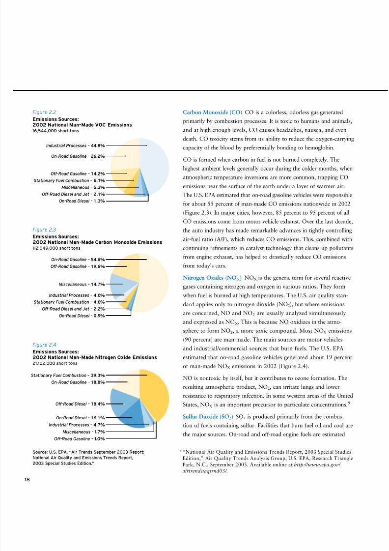
Global VOC emissions primarily come from vegetation (377 million metric tons carbon
equivalent annually), fossil fuels (161 million metric tons carbon equivalent annually), and
biomass burning (33 million metric tons carbon equivalent annually).7 In the 20-year period
from 1983 to 2002, anthropogenic VOC emissions in the U.S. decreased by 40 percent.8
On-road gasoline vehicles accounted for about 26 percent of man-made VOC emissions in
2002 (Figure 2.2), the last year for which U.S. EPA data are available.
Not all hydrocarbons contribute equally to ozone formation. Some are more reactive than
others, depending on their chemical structure and the atmospheric conditions to which they are
subjected. Under most conditions, olefins and aromatics are more reactive than paraffins.
4 “Air Trends, Ozone,” U.S. EPA, http://www.epa.gov/airtrends/ozone.html.
5 “Ozone – Good Up High Bad Nearby,” U.S. EPA, http://epa.gov/oar/oaqps/gooduphigh/.
6 VOC is the preferred term when discussing emissions. When the focus is on ozone formation, the termreactive organic gases (ROGs) is more common. The main difference is that VOC emissions include
methane and ethane, which do not participate in ozone formation and thus are not ROGs. Another
term sometimes used is non-methane organic gases (NMOGs). For simplicity, this review will use the
term VOC throughout.
7 “Emissions of Greenhouse Gases in the United States 2003,” Energy Information Administration,
Department of Energy, ftp://ftp.eia.doe.gov/pub/oiaf/1605/cdrom/pdf/ggrpt/057303.pdf.
8 “National Air Quality and Emissions Trends Report, 2003 Special Studies Edition,”Air Quality Trends Analysis Group, U.S. EPA, Research Triangle Park, N.C., September 2003.
Available online at http://www.epa.gov/airtrends/aqtrnd03/.17
8/9/2019 AAAAAAAA MotorGas Tech Review
http://slidepdf.com/reader/full/aaaaaaaa-motorgas-tech-review 26/124
18
9 “National Air Quality and Emissions Trends Report, 2003 Special Studies
Edition,” Air Quality Trends Analysis Group, U.S. EPA, Research Triangle
Park, N.C., September 2003. Available online at http://www.epa.gov/
airtrends/aqtrnd03/.
Carbon Monoxide (CO) CO is a colorless, odorless gas generated
primarily by combustion processes. It is toxic to humans and animals,
and at high enough levels, CO causes headaches, nausea, and even
death. CO toxicity stems from its ability to reduce the oxygen-carrying
capacity of the blood by preferentially bonding to hemoglobin.
CO is formed when carbon in fuel is not burned completely. The
highest ambient levels generally occur during the colder months, when
atmospheric temperature inversions are more common, trapping CO
emissions near the surface of the earth under a layer of warmer air.
The U.S. EPA estimated that on-road gasoline vehicles were responsible
for about 55 percent of man-made CO emissions nationwide in 2002
(Figure 2.3). In major cities, however, 85 percent to 95 percent of all
CO emissions come from motor vehicle exhaust. Over the last decade,
the auto industry has made remarkable advances in tightly controlling
air-fuel ratio (A/F), which reduces CO emissions. This, combined with
continuing refinements in catalyst technology that cleans up pollutants
from engine exhaust, has helped to drastically reduce CO emissions
from today’s cars.
Nitrogen Oxides (NOX) NOX is the generic term for several reactive
gases containing nitrogen and oxygen in various ratios. They formwhen fuel is burned at high temperatures. The U.S. air quality stan-
dard applies only to nitrogen dioxide (NO2), but where emissions
are concerned, NO and NO2 are usually analyzed simultaneously
and expressed as NOX. This is because NO oxidizes in the atmo-
sphere to form NO2, a more toxic compound. Most NOX emissions
(90 percent) are man-made. The main sources are motor vehicles
and industrial/commercial sources that burn fuels. The U.S. EPA
estimated that on-road gasoline vehicles generated about 19 percent
of man-made NOX emissions in 2002 (Figure 2.4).
NO is nontoxic by itself, but it contributes to ozone formation. The
resulting atmospheric product, NO2, can irritate lungs and lower
resistance to respiratory infection. In some western areas of the United
States, NOX is an important precursor to particulate concentrations.9
Sulfur Dioxide (SO2) SO2 is produced primarily from the combus-
tion of fuels containing sulfur. Facilities that burn fuel oil and coal are
the major sources. On-road and off-road engine fuels are estimated
Stationary Fuel Combustion – 6.1%
On-Road Gasoline – 26.2%
Off-Road Gasoline – 14.2%
Miscellaneous – 5.3%
Off-Road Diesel and Jet –
2.1%
On-Road Diesel – 1.3%
Industrial Processes – 44.8%
Industrial Processes – 4.0%
Off-Road Gasoline – 19.6%
Miscellaneous – 14.7%
Stationary Fuel Combustion – 4.0%
Off-Road Diesel and Jet – 2.2%
On-Road Diesel –
0.9%
On-Road Gasoline – 54.6%
On-Road Diesel – 16.1%
On-Road Gasoline – 18.8%
Off-Road Diesel – 18.4%
Industrial Processes – 4.7%
Miscellaneous – 1.7%
Off-Road Gasoline – 1.0%
Stationary Fuel Combustion – 39.3%
Figure 2.2
Emissions Sources:2002 National Man-Made VOC Emissions16,544,000 short tons
Figure 2.3
Emissions Sources:2002 National Man-Made Carbon Monoxide Emissions112,049,000 short tons
Figure 2.4
Emissions Sources:2002 National Man-Made Nitrogen Oxide Emissions21,102,000 short tons
Source: U.S. EPA, “Air Trends September 2003 Report:
National Air Quality and Emissions Trends Report,
2003 Special Studies Edition.”
8/9/2019 AAAAAAAA MotorGas Tech Review
http://slidepdf.com/reader/full/aaaaaaaa-motorgas-tech-review 27/124
8/9/2019 AAAAAAAA MotorGas Tech Review
http://slidepdf.com/reader/full/aaaaaaaa-motorgas-tech-review 28/124
20
Fuel Economy and Emissions
Intuition suggests that one engine
that burns more fuel than another
over a given distance would produce
more emissions, but that is not true.
Vehicle emissions standards for new
vehicles are set in terms of the mass of
pollutant emitted per distance traveled.
So, for example, a heavy, large-engine
passenger vehicle may burn twice as
much fuel as a lighter, small-engine
vehicle over a given distance, but both
vehicles must meet the same emis-
sions standards and both will produce
equivalent emissions per distance trav-
eled. The large-engine vehicle in this
example will, however, produce twice as
much CO2 as the small-engine vehicle.
CO2 is the result of complete oxidation
of the carbon atoms in gasoline, and
the amount of CO2 produced is directly
proportional to fuel economy. Pursuant
to a Supreme Court ruling in 2009,
the U.S. EPA issued a proposed finding
that greenhouse gases, including CO2 ,
contribute to air pollution that may
endanger public health or welfare. The
U.S. Congress and the U.S. EPA are
pursing legislation and regulation that
will reduce greenhouse gases, including
limits on fuels and vehicle economy. In
Europe, the auto industry has a target
of 140g CO2 /km for the new-car fleet
by 2008. Europe uses g CO2 /km as a
more appropriate fuel economy measure
because the fleet includes both gasoline-
and diesel-fueled passenger cars.
The Clean Air Act Amendments of 1990 classified the following as toxic air pollutants
related to gasoline and gasoline vehicles:
• Benzene • Formaldehyde
• Polycyclic organic matter (POM) • 1,3-Butadiene
• Acetaldehyde
The U.S. EPA calculates that these five toxic compounds comprise 3.8 percent of total
VOC emissions. About 70 percent of that amount is benzene. 1,3-Butadiene, formalde-
hyde, and acetaldehyde are not present in gasoline; they are formed during combustion.
Benzene is a known human carcinogen. Some POMs are also carcinogens, but the POM
content of gasoline and gasoline exhaust is so low as to be difficult to measure. The two
aldehydes are eye and throat irritants, and formaldehyde is a suspected human carcinogen.
ORIGIN OF VEHICLE EMISSIONS11
When fuel is burned with the correct amount of air in a gasoline-powered engine, the gases
that are left are predominantly water vapor, carbon dioxide, and nitrogen. All of these gases
are benign, although carbon dioxide is a greenhouse gas. Deviations from ideal combustion
lead to the production of some VOCs, CO, NOX, and PM10.12
As noted earlier, gasoline-powered vehicles tend to be the main source of CO emissions,
and they contribute substantially to urban VOC and NOX emissions. However, significantimprovement in emission controls on new cars has diminished their contribution of these
pollutants. New cars emit only modest amounts of PM10 and PM2.5, but vehicles that
are ill-maintained or tampered with can emit much more. Older diesel-powered vehicles
without particulate traps, on the other hand, are substantial emitters of PM10, PM2.5, and
NOX but only small emitters of CO and VOCs. (See figures 2.2, 2.3, and 2.4.)
Exhaust VOC The vast majority of gasoline is burned before combustion gases exit the
engine in a properly operating vehicle, but a small fraction, typically 1 percent to 5 percent,
escapes the combustion chamber unburned. These VOC emissions consist primarily of
unburned hydrocarbons, but partially burned oxygen-containing compounds such as
aldehydes are also present in small amounts. Most are removed by a vehicle’s catalytic
converter. The quantity of exhaust VOC emissions is influenced by many factors, including
engine design, controls, and condition; operating temperature; A/F; fuel system deposits;
and catalytic converter performance. If a vehicle has a malfunctioning component that
inhibits proper ignition or combustion, such as a bad spark plug, VOC emissions can be
many times higher than normal.
11 A significant amount of emissions-related information may be obtained from the U.S. EPA Office
of Transportation and Air Quality site at http://www.epa.gov/otaq/index.htm.
12 For details on pollutant formation and control in gasoline engines, see John B. Heywood,
Internal Combustion Engine Fundamentals, McGraw-Hill, New York, 1988.
8/9/2019 AAAAAAAA MotorGas Tech Review
http://slidepdf.com/reader/full/aaaaaaaa-motorgas-tech-review 29/124
21
Chapter 2
Gasoline and Air Quality
Evaporative VOC Exhaust gases are not the only source of VOC emissions from gasoline-
fueled vehicles. In fact, the U.S. EPA estimated that in 1990 more than half the VOCs
emitted from gasoline vehicles came from evaporation. Evaporative VOC emissions differ
from exhaust VOC emissions in that evaporative emissions contain no combustion products.
Because evaporative VOC emissions originate largely from gasoline vapor, their composi-
tion is weighted heavily toward the lowest boiling components of gasoline.
Gasoline vapor escapes from a typical vehicle at various points, including the fuel tank,
carburetor (on vehicles that use them), and intake manifold. In addition, liquid gasoline can
permeate plastic fuel tanks and elastomeric fuel hoses, and the permeation effects are greater
with ethanol-blended gasoline. Liquid gasoline can also leak or seep from fuel system compo-
nents or connections.13 Factors that influence the amount of evaporative emissions include:
• Fuel system design (see page 65) • Gasoline vapor pressure (see page 2)
• Component integrity • Gasoline composition
• Ambient temperature
Of course, a certain amount of gasoline vapor is lost during fueling, though most of it
may be collected by service station vapor recovery systems, where installed.
Carbon Monoxide CO is the result of incomplete combustion of fuel, and the main factor
influencing its production is the ratio of air to fuel in an engine combustion chamber. If the
mixture of air and gasoline is fuel-rich, that is, has insufficient air (O2) to convert all fuel carbonto carbon dioxide (CO2), the exhaust will contain a high level of CO. Fuel-rich operation can
result either by design or by accident.
Prior to the introduction of vehicle emissions standards, most gasoline vehicles ran slightly
fuel-rich most of the time and produced a lot of CO. Later, manufacturers designed vehicles
to minimize fuel enrichment but also to allow for short periods of enrichment to aid vehicle
starting and to increase power output under certain conditions. Today’s cleanest vehicles use
minimal or no cold-start enrichment. Power enrichment is being greatly reduced since the
U.S. EPA bolstered its vehicle certification requirements with the Supplemental Federal Test
Procedure (SFTP), which tests for emissions at high-speed and under high-power conditions.
Irrespective of its design, a vehicle may operate fuel-rich when its fuel supply or controlsystem accidentally malfunctions. The causes are many but include:
• Deterioration or failure of components such as the carburetor or oxygen sensor.
• Deposits formed over time in fuel injectors or carburetors by poor-quality gasoline.
• Maintenance deciencies such as maladjustment or neglect.
13 In these cases, the composition of the evaporative VOCs will be characteristic of the whole gasoline.
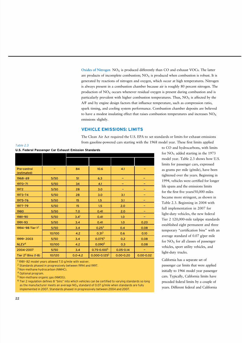
8/9/2019 AAAAAAAA MotorGas Tech Review
http://slidepdf.com/reader/full/aaaaaaaa-motorgas-tech-review 30/124
22
Oxides of Nitrogen NOX is produced differently than CO and exhaust VOCs. The latter
are products of incomplete combustion; NOX is produced when combustion is robust. It is
generated by reactions of nitrogen and oxygen, which occur at high temperatures. Nitrogen
is always present in a combustion chamber because air is roughly 80 percent nitrogen. The
production of NOX occurs whenever residual oxygen is present during combustion and is
particularly prevalent with higher combustion temperatures. Thus, NOX is affected by the
A/F and by engine design factors that influence temperature, such as compression ratio,
spark timing, and cooling system performance. Combustion chamber deposits are believed
to have a modest insulating effect that raises combustion temperatures and increases NOX
emissions slightly.
VEHICLE EMISSIONS: LIMITS
The Clean Air Act required the U.S. EPA to set standards or limits for exhaust emissions
from gasoline-powered cars starting with the 1968 model year. These first limits applied
to CO and hydrocarbons, with limits
for NOX added starting in the 1973
model year. Table 2.3 shows how U.S.
limits for passenger cars, expressed
as grams per mile (g/mile), have been
tightened over the years. Beginning in
1994, vehicles were certified for longer
life spans and the emissions limits
for the first five years/50,000 miles
became more stringent, as shown in
Table 2.3. Beginning in 2004 with
full implementation in 2007 for
light-duty vehicles, the new federal
Tier 2 120,000-mile tailpipe standards
established eight permanent and three
temporary “certification bins” with an
average standard of 0.07 g/per mile
for NOX for all classes of passenger
vehicles, sport utility vehicles, and
light-duty trucks.
California has a separate set of
passenger car limits that were applied
initially to 1966 model year passenger
cars. Typically, California limits have
preceded federal limits by a couple of
years. Different federal and California
Pre-control — 84 10.6 4.1 —
(estimated)
1968– 69 5/50 51 6.3 — —
1970–71 5/50 34 4.1 — —
1972 5/50 28 3.0 — —
1973–74 5/50 28 3.0 3.1 —
1975–76 5/50 15 1.5 3.1 —
1977–79 5/50 15 1.5 2.0 —
1980 5/50 7.0 0.41 2.0 —
1981–90 5/50 3.41 0.41 1.0 —
1991–93 5/50 3.4 0.41 1.0 0.20
1994—98 Tier 12 5/50 3.4 0.253 0.4 0.08
10/100 4.2 0.313 0.6 0.10
1999– 2003 5/50 3.4 0.0755
0.2 0.08NLEV4 10/100 4.2 0.0905 0.3 0.08
2004–2007 5/50
3.4 0.75-0.1005 0.05-0.14 —
Tier 26 Bins (1-8) 10/120 0.0-4.2 0.000-0.1255 0.00-0.20 0.00-0.02
Table 2.3
U.S. Federal Passenger Car Exhaust Emission Standards
1 1981– 82 model years allowed 7.0 g/mile with waiver. 2 Standards phased in progressively between 1994 and 1997. 3 Non-methane hydrocarbon (NMHC). 4 Optional program. 5 Non-methane organic gas (NMOG). 6 Tier 2 regulation denes 8 “bins” into which vehicles can be certied to varying standards so long
as the manufacturer meets an average NOX standard of 0.07 g/mile when standards are fully
implemented in 2007. Standards phased in progressively between 2004 and 2007.
Useful Life, Carbon Hydrocarbons Oxides of ParticulatesModel Year Years/1M Miles Monoxide (CO) (HC) Nitrogen (NOX) (PM10)
Maximum Emissions g/mile (FTP-75 Cycle)
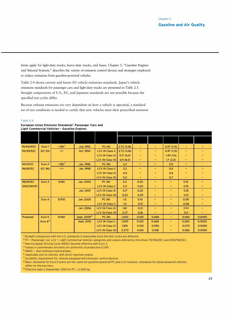
8/9/2019 AAAAAAAA MotorGas Tech Review
http://slidepdf.com/reader/full/aaaaaaaa-motorgas-tech-review 31/124
23
Chapter 2
Gasoline and Air Quality
limits apply for light-duty trucks, heavy-duty trucks, and buses. Chapter 5, “Gasoline Engines
and Selected Systems,” describes the variety of emission control devices and strategies employed
to reduce emissions from gasoline-powered vehicles.
Table 2.4 shows current and future EU vehicle emissions standards. Japan’s vehicle
emissions standards for passenger cars and light-duty trucks are presented in Table 2.5.
Straight comparisons of U.S., EU, and Japanese standards are not possible because the
specified test cycles differ.
Because exhaust emissions are very dependent on how a vehicle is operated, a standard
set of test conditions is needed to certify that new vehicles meet their prescribed emission
Table 2.4
European Union Emission Standards1 Passenger Cars and
Light Commercial Vehicles — Gasoline Engines
91/441/EEC Euro 1 —/807 July 1992 PC (M) 2.72 (3.16) — — 0.97 (1.13) — —
93/59/EEC (EC 93) —/— Oct. 1994 LCV (N Class I) 2.72 (3.16) — — 0.97 (1.13) — —
LCV (N Class II) 5.17 (6.0) — — 1.40 (1.6) — —
LCV (N Class III) 6.9 (8.0) — — 1.7 (2.0) — —
94/12/EC Euro 2 —/807 Jan. 1996 PC (M) 2.2 — — 0.5 — —
96/69/EC (EC 96) —/— Jan. 1998 LCV (N Class I) 2.2 — — 0.5 — —
LCV (N Class II) 4.0 — — 0.6 — —
LCV (N Class III) 5.0 — — 0.7 — —
98/69/EC Euro 3 5/80 Jan. 2000 PC (M) 2.3 0.20 — — 0.15 —
2002/80/EC LCV (N Class I) 2.3 0.20 — — 0.15 —
Jan. 2001 LCV (N Class II) 4.17 0.25 — — 0.18 —
LCV (N Class III) 5.22 0.29 — — 0.21 —
Euro 4 5/100 Jan. 2005 PC (M) 1.0 0.10 — — 0.08 —
LCV (N Class I) 1.0 0.10 — — 0.08 —
Jan. 2006 LCV (N Class II) 1.81 0.13 — — 0.10 —
LCV (N Class III) 2.27 0.16 — — 0.11 —
Proposed Euro 5 5/160 Sept. 20099 PC (M) 1.000 0.100 0.068 — 0.060 0.0050
Euro 68 Sept. 2010 LCV (N Class I) 1.000 0.100 0.068 — 0.060 0.0050
LCV (N Class II) 1.810 0.130 0.090 — 0.075 0.0050
LCV (N Class III) 2.270 0.160 0.108 — 0.082 0.0050
1 Straight comparison with the U.S. standards is impossible since the test cycles are different. 2 PC = Passenger Car; LCV = Light Commercial Vehicle; categories and classes dened by Directives 70/156/EEC and 2001/116/EEC. 3 New European Driving Cycle (NEDC) became effective with Euro 3. 4 Values in parentheses are limits on conformity of production (COP). 5 NMHC = Non-methane hydrocarbons. 6 Applicable only to vehicles with direct-injection engine. 7 Durability requirement for vehicles equipped with emission control devices.
8 Basic standards for Euro 5 and 6 are the same for gasoline-powered PC and LCV; however, standards for diesel-powered vehicles
differ for the two tiers. 9 Effective date is September 2010 for PC > 2,500 kg.
Effective DateUseful Life for New Type Vehicle Type2 Particulates
Directive Tier Years/1M Miles Approvals (Category) CO HC NMHC5 HC + NOX NOX (PM10)6
Maximum Emissions, g/km (ECE 15 + EUDC / NEDC) 3,4
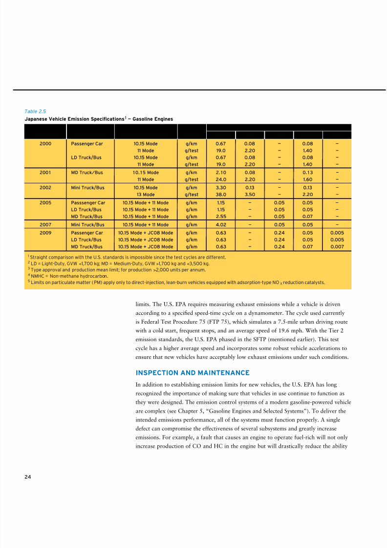
8/9/2019 AAAAAAAA MotorGas Tech Review
http://slidepdf.com/reader/full/aaaaaaaa-motorgas-tech-review 32/124
limits. The U.S. EPA requires measuring exhaust emissions while a vehicle is driven
according to a specified speed-time cycle on a dynamometer. The cycle used currently
is Federal Test Procedure 75 (FTP 75), which simulates a 7.5-mile urban driving route
with a cold start, frequent stops, and an average speed of 19.6 mph. With the Tier 2
emission standards, the U.S. EPA phased in the SFTP (mentioned earlier). This test
cycle has a higher average speed and incorporates some robust vehicle accelerations to
ensure that new vehicles have acceptably low exhaust emissions under such conditions.
INSPECTION AND MAINTENANCE
In addition to establishing emission limits for new vehicles, the U.S. EPA has long
recognized the importance of making sure that vehicles in use continue to function as
they were designed. The emission control systems of a modern gasoline-powered vehicle
are complex (see Chapter 5, “Gasoline Engines and Selected Systems”). To deliver the
intended emissions performance, all of the systems must function properly. A single
defect can compromise the effectiveness of several subsystems and greatly increase
emissions. For example, a fault that causes an engine to operate fuel-rich will not only
increase production of CO and HC in the engine but will drastically reduce the ability
24
Implementation
Year Vehicle Type2 Test Method Units CO HC NMHC4 NOX PM5
Mean Limits3
2000 Passenger Car 10.15 Mode g/km 0.67 0.08 — 0.08 —
11 Mode g/test 19.0 2.20 — 1.40 —
LD Truck/Bus 10.15 Mode g/km 0.67 0.08 — 0.08 —
11 Mode g/test 19.0 2.20 — 1.40 —
2001 MD Truck/Bus 10.15 Mode g/km 2.10 0.08 — 0.13 —
11 Mode g/test 24.0 2.20 — 1.60 —
2002 Mini Truck/Bus 10.15 Mode g/km 3.30 0.13 — 0.13 —
13 Mode g/test 38.0 3.50 — 2.20 —
2005 Passsenger Car 10.15 Mode + 11 Mode g/km 1.15 — 0.05 0.05 —
LD Truck/Bus 10.15 Mode + 11 Mode g/km 1.15 — 0.05 0.05 —
MD Truck/Bus 10.15 Mode + 11 Mode g/km 2.55 — 0.05 0.07 —
2007 Mini Truck/Bus 10.15 Mode + 11 Mode g/km 4.02 — 0.05 0.05 —
2009 Passenger Car 10.15 Mode + JC08 Mode g/km 0.63 — 0.24 0.05 0.005
LD Truck/Bus 10.15 Mode + JC08 Mode g/km 0.63 — 0.24 0.05 0.005
MD Truck/Bus 10.15 Mode + JC08 Mode g/km 0.63 — 0.24 0.07 0.007
Table 2.5
Japanese Vehicle Emission Specications1 — Gasoline Engines
1 Straight comparison with the U.S. standards is impossible since the test cycles are different. 2 LD = Light-Duty, GVW <1,700 kg; MD = Medium-Duty, GVW >1,700 kg and <3,500 kg. 3 Type approval and production mean limit; for production >2,000 units per annum. 4 NMHC = Non-methane hydrocarbon. 5 Limits on particulate matter (PM) apply only to direct-injection, lean-burn vehicles equipped with adsorption-type NOX reduction catalysts.
8/9/2019 AAAAAAAA MotorGas Tech Review
http://slidepdf.com/reader/full/aaaaaaaa-motorgas-tech-review 33/124
25
Chapter 2
Gasoline and Air Quality
of the catalyst to eliminate these pollutants, thus increasing their emission by a factor of
perhaps 10 or more. When this happens, one “broken” vehicle can pollute as much as 10
properly functioning vehicles can. Thus, regular inspection of an engine and its emission
controls, plus prompt and effective repair of any defects, can be as important to clean air
as requiring the controls initially.
In 1983, the U.S. EPA oversaw the introduction of Inspection and Maintenance (I/M)
programs in a number of states with air quality problems. These mandatory programs,
often referred to as smog inspections, require a vehicle to undergo a set of inspections
to detect if its emission control systems are defective or have been tampered with. The
inspections may be conducted at state-run facilities or at privately owned shops. Most
involve visually checking a vehicle for obviously broken, damaged, or missing emission
control components and measuring tailpipe emissions. If a vehicle fails any of the tests, its
owner usually is required to have the affected items repaired, subject to certain cost limits.
The 1990 Clean Air Act Amendments require a number of regions in the U.S. to implement
more stringent I/M programs.14
Today’s new vehicles have mandatory systems called on-board diagnostics (OBD) that can
identify many of the problems that lead to significant increases in emissions (for example,
problems with the catalytic converter or with the exhaust oxygen sensor that is part of the
closed-loop A/F control system). Eventually, OBD may obviate the need for I/M programs.
VEHICLE EMISSIONS: GASOLINE EFFECTS
Changes in gasoline properties and composition can help reduce vehicle emissions. Certain
gasoline modifications are very effective at enabling vehicle emission control systems to
perform at their optimum levels. Other gasoline modifications are not nearly as effective at
reducing emissions compared to the use of the vehicle emission control systems described
in Chapter 5, “Gasoline Engines and Selected Systems.” The explanations here apply
chiefly to vehicles built since 1985.
Sulfur Sulfur in fuel becomes sulfur oxides in exhaust that temporarily poison the
three-way catalyst. Reducing gasoline’s sulfur content increases converter efficiency and
decreases VOC, CO, NOX, and toxics emissions. Sulfur also interferes with OBD catalyst
monitoring sensor performance in lean-burn engines.
Although gasoline engines are not a major source of SO2, a criteria pollutant, reducing
gasoline sulfur content also reduces the direct emission of this pollutant.
Vapor Pressure Decreasing the vapor pressure of gasoline reduces evaporative VOC
emissions and, to a lesser extent, can reduce exhaust VOC and CO.
14 Detailed information regarding I/M programs can be obtained from the U.S. EPA National Vehicle
and Fuel Emission Laboratory, 2000 Traverwood Drive, Ann Arbor, Michigan 48105. Regulations
regarding I/M programs can be found in the U.S. Code of Federal Regulations, Volume 40, Part 51
(40 CFR 51), Subpart S.
8/9/2019 AAAAAAAA MotorGas Tech Review
http://slidepdf.com/reader/full/aaaaaaaa-motorgas-tech-review 34/124
26
Oxygenates As explained earlier, CO is a result of incomplete combustion, and its forma-
tion is very dependent on A/F. In older cars, adding oxygenates to gasoline has the same
effect as increasing the amount of combustion air. Oxygenated gasolines add more oxygen
to a combustion chamber, make combustion more complete, and help reduce formation of
carbon monoxide.
Oxygenates also tend to reduce exhaust VOC emissions somewhat, but they increase
aldehyde emissions and tend to increase NOX emissions in many vehicles. As explained
previously, NOX formation is increased by excess oxygen and higher combustion tempera-
tures. This relationship between oxygen and increased NOX caused California and,
until recently, the U.S. EPA to limit the oxygen content of reformulated gasolines.The
emissions benefit of oxygenates was greatest in pre-1990 vehicles with less effective A/F
control systems than the closed-loop A/F control systems in newer vehicles. By adjusting
intake A/F based on the oxygen content of exhaust, the newer systems compensate for
oxygen in fuel, negating most of the emissions benefit associated with using oxygenated
gasoline. The addition of adaptive learning systems has improved A/F control even more.
Consequently, oxygenates seem to have little effect on exhaust emissions from newer
vehicles, so long as the vehicles are operating in closed-loop mode.
Because of recent advances in automotive technology, the U.S. EPA has acknowledged
that the oxygen component of RFG is not required to achieve the air quality benefits that
were targeted by the Clean Air Act Amendments of 1990. With the Energy Policy Actof 2005, the U.S. Congress directed the U.S. EPA to rescind the requirement that federal
RFG must contain oxygenated components. This was implemented in 2006. Although the
U.S. EPA no longer requires the use of oxygenates in these gasolines, almost all gasolines
used in federal RFG areas and in California are blended with ethanol and are therefore
still oxygenated gasolines.
Olefins Increasing the olefin content of gasoline tends to reduce exhaust VOC emissions
because olefins burn more easily and more completely than the other classes of hydrocar-
bons in gasoline. However, increasing olefin content also tends to increase NOX formation.
It also increases the olefin content of evaporative emissions, which is undesirable because
olefins are among the most reactive hydrocarbons for ozone formation. For reformulated
gasolines, the choice is to decrease olefins.
Aromatics Decreasing the total aromatics content of gasoline may reduce CO and exhaust
VOC emissions, but the effects are variable and complex, probably because the aromatic
compounds in gasoline are so diverse. Decreasing aromatics content reduces benzene
in vehicle exhaust emissions because larger aromatic molecules are partly converted to
benzene during combustion or in the catalytic converter.
Benzene Decreasing the benzene content of gasoline reduces the amount of benzene in both
evaporative and exhaust VOC emissions.
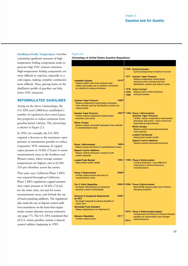
8/9/2019 AAAAAAAA MotorGas Tech Review
http://slidepdf.com/reader/full/aaaaaaaa-motorgas-tech-review 35/124
27
Chapter 2
Gasoline and Air Quality
Distillation Profile Temperatures Gasoline
containing significant amounts of high-
temperature boiling components tends to
generate high VOC exhaust emissions.
High-temperature boiling components are
more difficult to vaporize, especially in a
cold engine, making complete combustion
more difficult. Thus, placing limits on the
distillation profile of gasoline can help
lower VOC emissions.
REFORMULATED GASOLINES
Acting on the above relationships, the
U.S. EPA and CARB have established a
number of regulations that control gaso-
line properties to reduce emissions from
gasoline-fueled vehicles. The chronology
is shown in Figure 2.5.
In 1992, for example, the U.S. EPA
required a decrease in the maximum vapor
pressure of summertime gasoline to reduce
evaporative VOC emissions. It capped
vapor pressure at 54 kPa (7.8 psi) in ozone
nonattainment areas in the Southern and
Western states, where average summer
temperatures are highest, and at 62 kPa
(9.0 psi) elsewhere across the nation.
That same year, California Phase 1 RFG
was required throughout California.
Phase 1 RFG regulations capped summer-
time vapor pressure at 54 kPa (7.8 psi)for the entire state, not just for ozone
nonattainment areas, and forbade the use
of lead-containing additives. The regulations
also made the use of deposit control addi-
tives mandatory on the basis that engine
intake system deposits increase emissions
(see page 77). The U.S. EPA mandated that
all U.S. motor gasoline contain a deposit
control additive beginning in 1995.
Figure 2.5
Chronology of United States Gasoline Regulations
Federal California
1960 Bromine Number
Control/reduce the formation of ozone
Phase 3 Reformulated Update
Compensate for effects of ethanol-blendedgasoline on hydrocarbon and nitrogenoxide emissions
2010
2012
1974Unleaded Gasoline
Reduce health risks from airborne leadoxides and enable use of catalytic converterson vehicles to reduce emissions
1989Summer Vapor Pressure
Reduce evaporative hydrocarbon emissionsfrom vehicles and fuel distribution system andreduce ozone
19921992
Winter Oxygen
Reduce carbon monoxide emissions from vehiclesin nonattainment areas
Summer Vapor Pressure
Further reduce evaporative hydrocarbonemissions and ozone
Phase 1 Reformulated
(Summer Vapor Pressure)
Further reduce evaporative hydrocarbonemissions and ozone – more restrictivethan federal requirements
Deposit Control Additives
Reduce carbon monoxide emissions
Winter Oxygen
Reduce carbon monoxide emissionsfrom vehicles
Leaded Fuel Banned
Help protect public health
Leaded Fuels Banned
Help protect public healthPhase 2 Reformulated
Achieve maximum “cost-effective”reductions in vehicle emissions,including toxics
19961996
Tier 2 Sulfur Regulation
Increases effectiveness of advancedemission control technologies
Phase 3 Reformulated
Bans MTBE and provides more reneryblending exibility
20042004
Phase I Reformulated
Reduce ozone and toxics in nonattainment areas
Deposit Control Additives
Reduce vehicle emissions caused by fuelsystem deposits
1995
1971 Summer Vapor Pressure
Reduce evaporative hydrocarbonemissions from vehicles and fueldistribution system and reduce ozone
Sulfur Content
Reduce sulfur oxide emissionsand particulates
1976
1978
1980
Phase II Reformulated
Further reduce ozone and toxics innonattainment areas
Renewable Fuels Standard
Reduce dependence on imported oil
2000
Removal of Oxygenate Requirement
for RFG
No longer required to achieve benets innewer cars
2006
Benzene Regulation
Further reduce toxics
2011
8/9/2019 AAAAAAAA MotorGas Tech Review
http://slidepdf.com/reader/full/aaaaaaaa-motorgas-tech-review 36/124
28
The year 1992 also saw implementation of the U.S. EPA’s winter oxygenate program,
which required the addition of oxygenates to gasoline sold in the 39 areas of the country
that had not attained the NAAQS for CO. Gasoline in these areas was required to contain
a minimum of 2.7 mass percent oxygen during the winter months when CO emissions tend
to be highest. The four or five applicable winter months varied from area to area. Most of
the original 39 areas have now attained the NAAQS for CO. However, eight areas in the
Western U.S. continue to participate in the winter oxygenate program.15
In 1995, the U.S. EPA introduced regulations for Federal Phase I RFG to be used in the
nine extreme or severe ozone nonattainment areas across the country.16 Less severe ozone
nonattainment areas were allowed to opt into the RFG program.
The U.S. EPA fixed two characteristics of Federal Phase I RFG. The average benzene content
had to be less than 1 volume percent and the average year-round oxygen content had to be
greater than 2.1 mass percent. Summertime vapor pressure also was limited. Otherwise, the
general approach was to set vehicle emission reduction targets rather than place property or
composition limits on gasoline. To make this work, the U.S. EPA provided refiners with a
Simple Model, which expired in 1998, and a Complex Model, a more detailed mathematical
model that relates gasoline composition to vehicle emissions. Criteria entered into the Complex
Model are essentially those gasoline properties listed in the previous section. The model results
are predicted levels of VOC, NOX, and toxics emissions from a standard in-use vehicle fleet.
The Complex Model helps refiners meet the prescribed vehicle emissions reductions in the mostcost-effective way for each particular refinery.
In mid-1996, CARB introduced its Phase 2 RFG regulation. In its initial form, the regula-
tion created a recipe for gasoline by specifying eight parameters of gasoline volatility and
composition. It placed limits on summertime vapor pressure, benzene, total aromatics, olefins
and sulfur content as well as the temperatures for the 50 percent and 90 percent evaporated
points from the distillation profile. It also required a minimum oxygen content year-round.
CARB subsequently modified the Phase 2 RFG regulation, allowing refiners to certify alterna-
tive compositions through the California Predictive Model. This model is similar to the
U.S. EPA’s Complex Model in concept but different in some particulars. CARB’s intent was
to reduce the cost of producing Phase 2 RFG by allowing refiners to show that an alternative
gasoline (presumably less expensive to produce) would reduce vehicle emissions at least as
much as the original Phase 2 recipe. Even when the Predictive Model is used, however, the
eight parameters still place limits on gasoline volatility and composition. Some of these limits
are less stringent than the equivalent limits in the original recipe but are still quite restrictive.
15 “State Winter Oxygenated Fuel Program Requirements for Attainment or Maintenance of
CO NAAQS,” U.S. EPA, January 2008. Available online at http://www.epa.gov/otaq/regs/ fuels/420b08006.pdf.
16 The number of areas increased to 10 in 1996 with the addition of Sacramento, California,
and then to 11 in 2002 with the addition of the San Joaquin Valley in California.
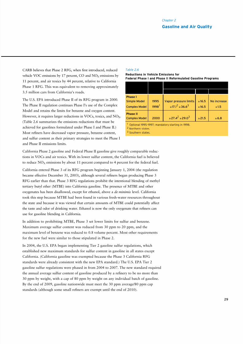
8/9/2019 AAAAAAAA MotorGas Tech Review
http://slidepdf.com/reader/full/aaaaaaaa-motorgas-tech-review 37/124
29
Chapter 2
Gasoline and Air Quality
CARB believes that Phase 2 RFG, when first introduced, reduced
vehicle VOC emissions by 17 percent, CO and NOX emissions by
11 percent, and air toxics by 44 percent, relative to California
Phase 1 RFG. This was equivalent to removing approximately
3.5 million cars from California’s roads.
The U.S. EPA introduced Phase II of its RFG program in 2000.
The Phase II regulation continues Phase I’s use of the Complex
Model and retains the limits for benzene and oxygen content.
However, it requires larger reductions in VOCs, toxics, and NOX.
(Table 2.6 summarizes the emissions reductions that must be
achieved for gasolines formulated under Phase I and Phase II.)
Most refiners have decreased vapor pressure, benzene content,
and sulfur content as their primary strategies to meet the Phase I
and Phase II emissions limits.
California Phase 2 gasoline and Federal Phase II gasoline give roughly comparable reduc-
tions in VOCs and air toxics. With its lower sulfur content, the California fuel is believed
to reduce NOX emissions by about 11 percent compared to 4 percent for the federal fuel.
California entered Phase 3 of its RFG program beginning January 1, 2004 (the regulation
became effective December 31, 2003), although several refiners began producing Phase 3
RFG earlier than that. Phase 3 RFG regulations prohibit the intentional blending of methyltertiary butyl ether (MTBE) into California gasoline. The presence of MTBE and other
oxygenates has been disallowed, except for ethanol, above a de minimis level. California
took this step because MTBE had been found in various fresh-water resources throughout
the state and because it was viewed that certain amounts of MTBE could potentially affect
the taste and odor of drinking water. Ethanol is now the only oxygenate that refiners can
use for gasoline blending in California.
In addition to prohibiting MTBE, Phase 3 set lower limits for sulfur and benzene.
Maximum average sulfur content was reduced from 30 ppm to 20 ppm, and the
maximum level of benzene was reduced to 0.8 volume percent. Most other requirements
for the new fuel were similar to those stipulated in Phase 2.
In 2004, the U.S. EPA began implementing Tier 2 gasoline sulfur regulations, which
established new maximum standards for sulfur content in gasoline in all states except
California. (California gasoline was exempted because the Phase 3 California RFG
standards were already consistent with the new EPA standard.) The U.S. EPA Tier 2
gasoline sulfur regulations were phased in from 2004 to 2007. The new standard required
the annual average sulfur content of gasoline produced by a refinery to be no more than
30 ppm by weight, with a cap of 80 ppm by weight on any individual batch of gasoline.
By the end of 2009, gasoline nationwide must meet the 30 ppm average/80 ppm cap
standards (although some small refiners are exempt until the end of 2010).
Phase I
Simple Model 1995 Vapor pressure limits ≥ 16.5 No increase
Complex Model 19981 ≥ 17.12 ≥36.63 ≥ 16.5 ≥ 1.5
Phase II
Complex Model 2000 ≥27.42 ≥29.03 ≥21.5 ≥6.8
Table 2.6
Reductions in Vehicle Emissions for
Federal Phase I and Phase II Reformulated Gasoline Programs
1 Optional 1995–1997; mandatory starting in 1998.2 Northern states.3 Southern states.
Effective
Date VOC Toxics NOx
Reduction in Emissions, % (Averaged Standard,Compared to 1990 Baseline Renery Gasoline)
8/9/2019 AAAAAAAA MotorGas Tech Review
http://slidepdf.com/reader/full/aaaaaaaa-motorgas-tech-review 38/124
30
In 2007, the U.S. EPA promulgated new regulations for benzene content in gasoline as part
of the Control of Hazardous Air Pollutants from Mobile Sources regulation. This regulation
established an annual average maximum benzene content in gasoline of 0.62 liquid volume
percent, and it becomes effective January 1, 2011. Its objective is to further reduce the
toxics content of gasoline exhaust.
Also in 2007, the U.S. EPA finalized regulations for the Renewable Fuel Standard (RFS),
which was authorized by the Energy Policy Act of 2005. The RFS establishes a minimum
requirement for the volume of renewable fuels blended into gasoline and diesel fuel. The
national minimum volume requirement started at 4.0 billion gallons per year of renewable
fuel in 2006 and increases to 7.5 billion gallons per year in 2012. Each producer and
importer of gasoline in the U.S. is obligated to demonstrate compliance with this require-
ment based on the pro rata share of gasoline it produces or imports. With the passage of
the Energy Independence and Security Act of 2007, the amount of renewable fuels
required was increased to 15.2 billion gallons per year in 2012 and ends with a require-
ment of 36.0 billion per year by 2022. The proportional requirement for cellulosic biofuel
in the act begins in 2010 and scales up to 16.0 billion gallons per year by 2022.
In 2007, CARB updated its Phase 3 RFG gasoline standards to address issues related to
increased hydrocarbon emissions that resulted when the state switched from MTBE-blended
gasoline to ethanol-blended gasoline in 2003. The increased hydrocarbon emissions result
from ethanol-enhanced permeation of seals, hoses, and gaskets in vehicle fuel systems. Basedon additional vehicle testing data, the California Phase 3 RFG Predictive Model was revised
to account for the increased permeation emissions, requiring refiners to reduce the volatility
of their base gasoline. In addition, the maximum sulfur content standard was also reduced to
further control NOX emissions and prevent any backsliding on NOX that might be associated
with blending ethanol at higher concentrations in the future. The revised Phase 3 RFG
gasoline standards will phase in beginning in 2010, with full implementation by 2012.
On January 18, 2007, the governor of California issued an executive order establishing a
Low Carbon Fuels Standard (LCFS) for transportation fuels sold in California. The imple-
mentation details are under development.
European UnionIn 2005, the EU initiated sulfur-content reductions in a move toward a 10 ppm maximum for
all gasolines by 2009. The EU also limits aromatics to a maximum content of 35.0 volume
percent. In addition to enforcing gasoline content limits, the EU helps states manage fuel
availability through guidance on number and distance between refueling stations. These EU
mandates are based on European Committee for Standardization specification CEN EN 228.
Japan
In 2007, Japanese Industrial Standard (JIS) K 2202 for motor gasoline limited sulfur content
to 10 ppm maximum and summertime vapor pressure to 9.4 psi (65 kPa) maximum.
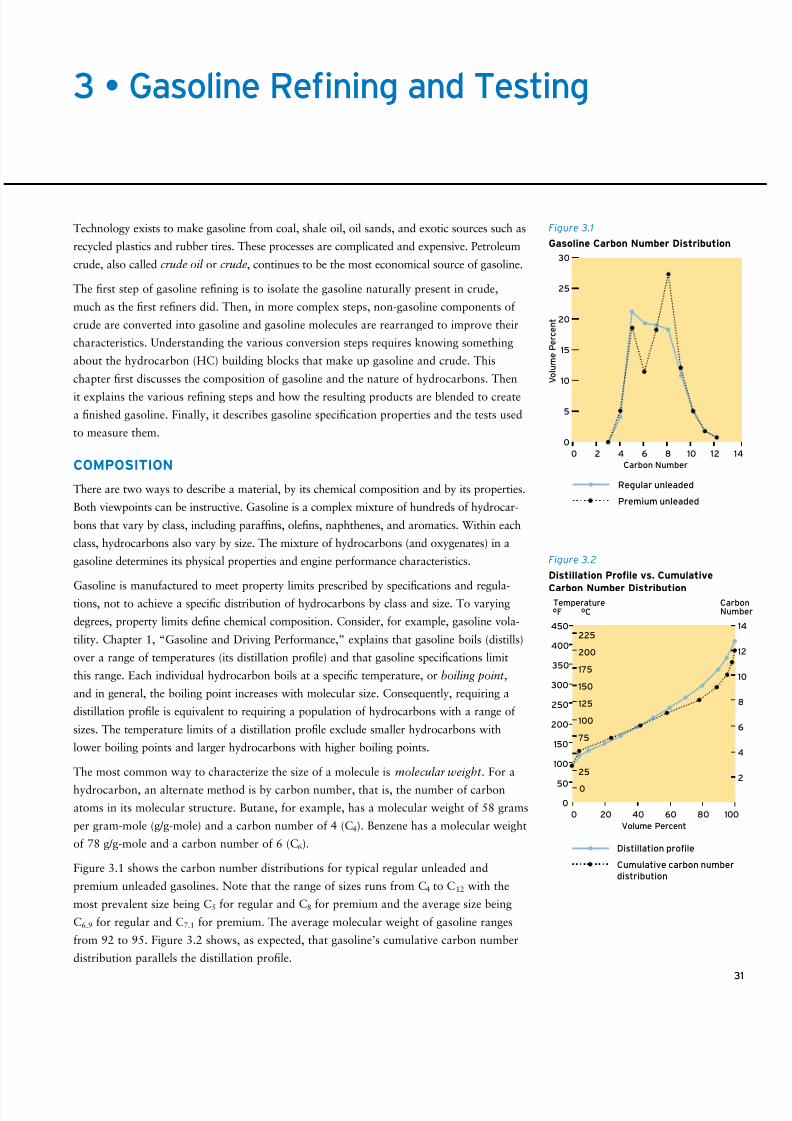
8/9/2019 AAAAAAAA MotorGas Tech Review
http://slidepdf.com/reader/full/aaaaaaaa-motorgas-tech-review 39/124
31
Technology exists to make gasoline from coal, shale oil, oil sands, and exotic sources such as
recycled plastics and rubber tires. These processes are complicated and expensive. Petroleum
crude, also called crude oil or crude, continues to be the most economical source of gasoline.
The first step of gasoline refining is to isolate the gasoline naturally present in crude,
much as the first refiners did. Then, in more complex steps, non-gasoline components of
crude are converted into gasoline and gasoline molecules are rearranged to improve their
characteristics. Understanding the various conversion steps requires knowing something
about the hydrocarbon (HC) building blocks that make up gasoline and crude. This
chapter first discusses the composition of gasoline and the nature of hydrocarbons. Then
it explains the various refining steps and how the resulting products are blended to create
a finished gasoline. Finally, it describes gasoline specification properties and the tests used
to measure them.
COMPOSITION
There are two ways to describe a material, by its chemical composition and by its properties.
Both viewpoints can be instructive. Gasoline is a complex mixture of hundreds of hydrocar-
bons that vary by class, including paraffins, olefins, naphthenes, and aromatics. Within each
class, hydrocarbons also vary by size. The mixture of hydrocarbons (and oxygenates) in a
gasoline determines its physical properties and engine performance characteristics.
Gasoline is manufactured to meet property limits prescribed by specifications and regula-tions, not to achieve a specific distribution of hydrocarbons by class and size. To varying
degrees, property limits define chemical composition. Consider, for example, gasoline vola-
tility. Chapter 1, “Gasoline and Driving Performance,” explains that gasoline boils (distills)
over a range of temperatures (its distillation profile) and that gasoline specifications limit
this range. Each individual hydrocarbon boils at a specific temperature, or boiling point ,
and in general, the boiling point increases with molecular size. Consequently, requiring a
distillation profile is equivalent to requiring a population of hydrocarbons with a range of
sizes. The temperature limits of a distillation profile exclude smaller hydrocarbons with
lower boiling points and larger hydrocarbons with higher boiling points.
The most common way to characterize the size of a molecule is molecular weight . For a
hydrocarbon, an alternate method is by carbon number, that is, the number of carbon
atoms in its molecular structure. Butane, for example, has a molecular weight of 58 grams
per gram-mole (g/g-mole) and a carbon number of 4 (C4). Benzene has a molecular weight
of 78 g/g-mole and a carbon number of 6 (C6).
Figure 3.1 shows the carbon number distributions for typical regular unleaded and
premium unleaded gasolines. Note that the range of sizes runs from C4 to C12 with the
most prevalent size being C5 for regular and C8 for premium and the average size being
C6.9 for regular and C7.1 for premium. The average molecular weight of gasoline ranges
from 92 to 95. Figure 3.2 shows, as expected, that gasoline’s cumulative carbon number
distribution parallels the distillation profile.
3 • Gasoline Refining and Testing
V o l u m e P e r c e n t
0 2 4 6 8 10 12 14
0
5
10
15
20
25
30
Carbon Number
Regular unleaded
Premium unleaded
Figure 3.1
Gasoline Carbon Number Distribution
Volume Percent
CarbonNumberºF ºC
Temperature
0 20 40 60 80 100
0
100
50
200
150
250
300
400
225
200
175
150
125
100
75
25
0
350
450
4
2
6
8
10
14
12
Distillation profle
Cumulative carbon number
distribution
Figure 3.2
Distillation Prole vs. Cumulative
Carbon Number Distribution
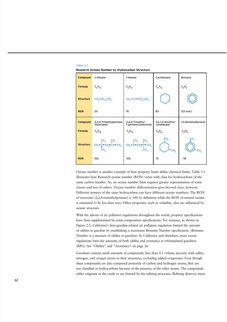
8/9/2019 AAAAAAAA MotorGas Tech Review
http://slidepdf.com/reader/full/aaaaaaaa-motorgas-tech-review 40/124
32
Octane number is another example of how property limits define chemical limits. Table 3.1
illustrates how Research octane number (RON) varies with class for hydrocarbons of the
same carbon number. So, an octane number limit requires greater representation of some
classes and less of others. Octane number differentiation goes beyond class, however.
Different isomers of the same hydrocarbon can have different octane numbers. The RON
of isooctane (2,2,4-trimethylpentane) is 100 by definition while the RON of normal octane
is estimated to be less than zero. Other properties, such as volatility, also are influenced by
isomer structure.
With the advent of air pollution regulations throughout the world, property specifications
have been supplemented by some composition specifications. For instance, as shown in
Figure 2.5, California’s first gasoline-related air pollution regulation limited the amountof olefins in gasoline by establishing a maximum Bromine Number specification. (Bromine
Number is a measure of olefins in gasoline). In California and elsewhere, more recent
regulations limit the amounts of both olefins and aromatics in reformulated gasolines
(RFG). See “Olefins” and “Aromatics” on page 26.
Gasolines contain small amounts of compounds (less than 0.1 volume percent) with sulfur,
nitrogen, and oxygen atoms in their structures, excluding added oxygenates. Even though
these compounds are also composed primarily of carbon and hydrogen atoms, they are
not classified as hydrocarbons because of the presence of the other atoms. The compounds
either originate in the crude or are formed by the refining processes. Refining destroys many
25RON 76 83 123 (est.)
100 106 72 118
Compound n-Hexane 1-Hexene Cyclohexane Benzene
2,2,4-Trimethylpentane(Isooctane)
2,4,4-Trimethyl-1-pentene (Isooctene)
Cis 1,3-dimethyl-cyclohexane
1,3-Dimethylbenzene
C8H
16
CH2C CH
2C CH
3
CH3
CH3
CH3
C8H
18
C6H
14
CH3(CH
2)4CH
3
C6H
12C
6H
12C
6H
6
CH2CH(CH
2)3CH
3
CH3 C CH
2CH CH
3
CH3
CH3
CH3
C8H
16C
8H
10
CH3
CH3
CH3
CH3
Structure
Formula
RON
Compound
Structure
Formula
Table 3.1
Research Octane Number by Hydrocarbon Structure
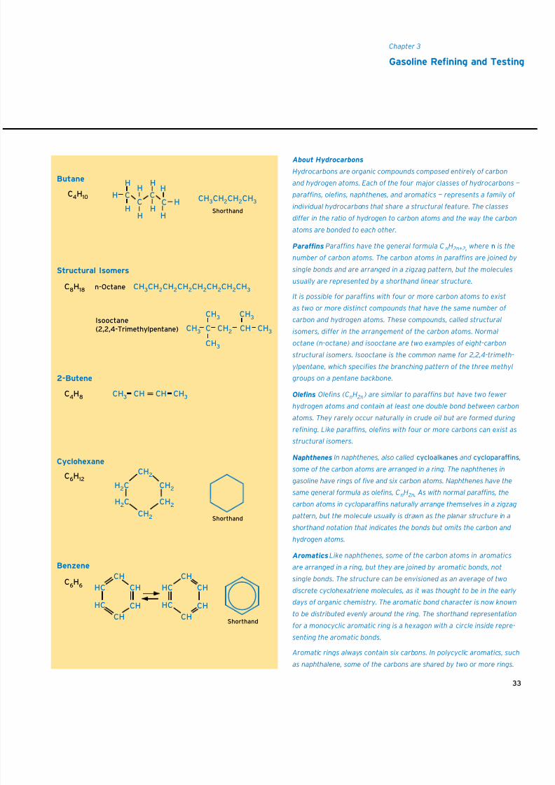
8/9/2019 AAAAAAAA MotorGas Tech Review
http://slidepdf.com/reader/full/aaaaaaaa-motorgas-tech-review 41/124
8/9/2019 AAAAAAAA MotorGas Tech Review
http://slidepdf.com/reader/full/aaaaaaaa-motorgas-tech-review 42/124
34
1 Straight-run products are those isolated from crude by simple distillation.
Continuous Processing
The change from a batch to a continuous
flow process was a major step in the
evolution of petroleum refining. Today,
almost all processes are continuous flow
because it would be impossible for a
modern refinery to process the current
volume of crude using batch processes.
nitrogen- and, particularly, sulfur-containing compounds, but some survive. Reducing the
sulfur content of gasoline is required by California Phase 3 RFG regulations and by
U.S. Environmental Protection Agency (EPA) Tier 2 sulfur regulations, and it is a major
factor in complying with U.S. EPA Tier 2 and California vehicle emissions regulations.
REFINING
Raw Material
As it comes out of the ground, petroleum crude can be as thin and light-colored as apple
cider or as thick and black as melted tar. Thin (low-density) crudes have high American
Petroleum Institute (API) gravities and therefore are called high-gravity crudes; conversely,
thick (high-density) crudes are low-gravity crudes. High-gravity crudes contain more natural
gasoline, and their lower sulfur and nitrogen contents make them easier to refine. Modern
refining processes are now capable of turning low-gravity crudes into high-value products
such as gasoline. Outside of the U.S., light crude refers to a low-density crude and heavy
crude to a high-density crude oil.
All crudes are composed primarily of hydrocarbons of the paraffinic, naphthenic, and
aromatic classes. Each class covers a very broad range of molecular weights.
Refining Processes
Today’s refinery is a complex combination of interdependent processing units, the result
of a fascinating intertwining of advances in chemistry, engineering, and metallurgy.
Refining started with the simple physical separation process called distillation.
Distillation In the late 1800s, crude was separated into different products by boiling. As
a means for isolating petroleum contents, distillation works because crudes are composed
of hydrocarbons with a broad range of molecular weights and, therefore, a broad range
of boiling points. Each product was assigned a temperature range and the product was
obtained by condensing the vapor that boiled off in this range at atmospheric pressure
(atmospheric distillation). The earliest distillation process simply involved a container in
which crude was heated and an attached condenser to condense vapor. Later, distillation
became a continuous process with a pump to provide crude flow, a furnace to heat crude
oil, and a distillation column to separate different boiling cuts.
In a distillation column, the vapor of the lowest-boiling hydrocarbons, propane and butane,
rises to the top. The straight-run gasoline (also called naphtha), kerosene, and diesel fuel cuts
are drawn off at successively lower positions in the column (see Figure 3.3).1 Hydrocarbons
with boiling points higher than diesel fuel aren’t vaporized; called atmospheric bottoms,
they remain in liquid form and fall to the bottom of the column.
Initially, atmospheric bottoms were used for paving and sealing. Later it was discovered
that distilling atmospheric bottoms in a vacuum yielded higher-value products such as
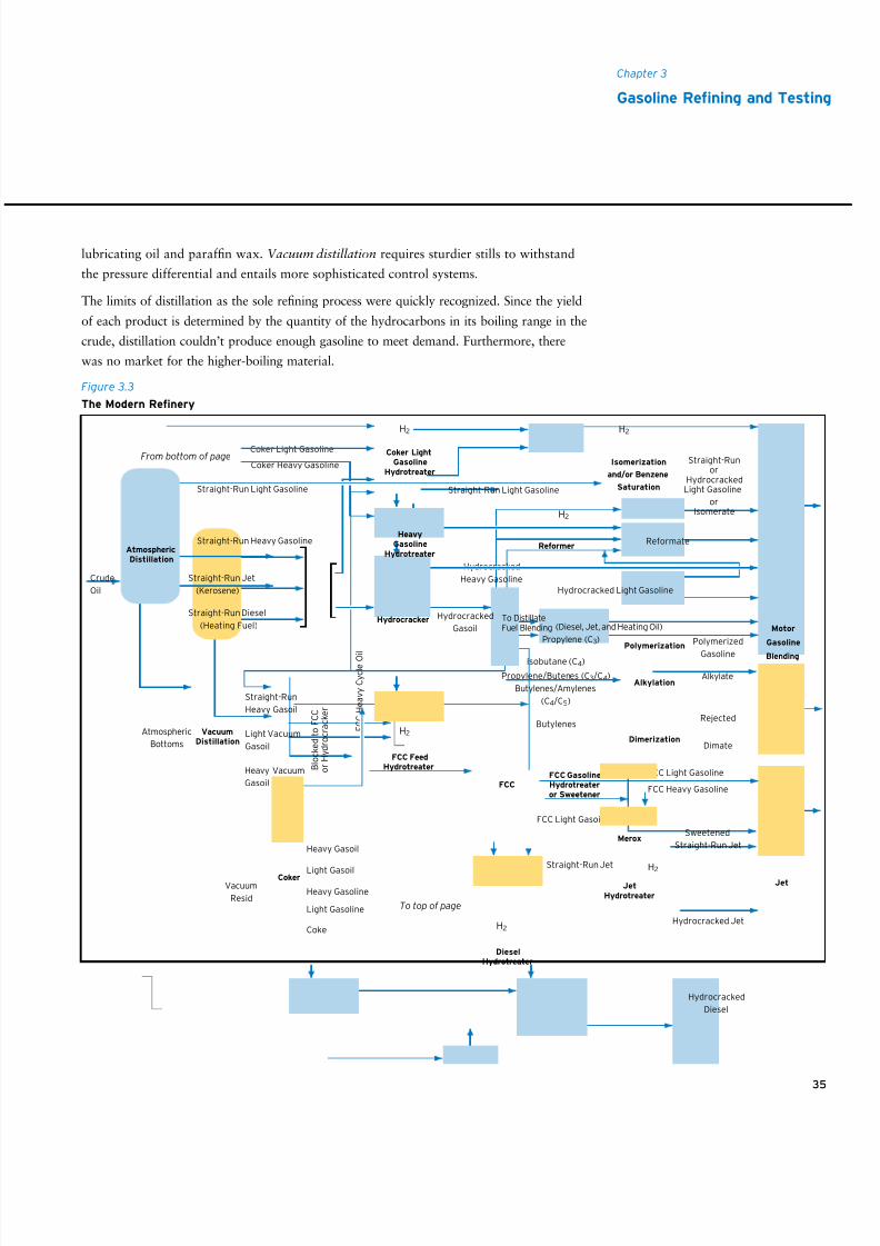
8/9/2019 AAAAAAAA MotorGas Tech Review
http://slidepdf.com/reader/full/aaaaaaaa-motorgas-tech-review 43/124
35
Chapter 3
Gasoline Rening and Testing
Crude
Oil
Atmospheric
Bottoms
Straight-Run
Heavy Gasoil
Straight-Run Light Gasoline Straight-Run Light Gasoline
Coker Light Gasoline
Coker Heavy GasolineFrom bottom of page
Straight-Run Heavy Gasoline
Straight-Run Jet
(Kerosene)
Straight-Run Diesel
(Heating Fuel)
Light Vacuum
Gasoil
Heavy Vacuum
Gasoil
Propylene (C3)
Isobutane (C4)
Propylene/Butenes (C3/C4)
Butylenes/Amylenes
(C4/C5)
Hydrocracked
Gasoil
Hydrocracked
Heavy Gasoline
Isomerization
and/or Benzene
Saturation
Polymerization
Alkylation
Reformer
Straight-Runor
HydrocrackedLight Gasoline
orIsomerate
Reformate
Polymerized
Gasoline
Alkylate
FCC Light Gasoline
FCC Heavy Gasoline
FCC Light Gasoil
Rejected
Dimate
Coker LightGasoline
Hydrotreater
Vacuum
Resid
VacuumDistillation
B l o c k e d t o
F C C
o r H y d r o c r a c k e r
Motor
Gasoline
Blending
Jet
Diesel
To DistillateFuel Blending
To top of page
Light Gasoil
F C C
H e a v y C y c l e O i l
FCC
Butylenes
FCC GasolineHydrotreateror Sweetener
Dimerization
Heavy Gasoline
Light Gasoline
Coke
Straight-Run Diesel
H2 H2
H2
H2
H2
H2
HeavyGasoline
Hydrotreater
FCC FeedHydrotreater
DieselHydrotreater
AtmosphericDistillation
Coker
Hydrocracked Light Gasoline
Hydrocracker
Sweetened
Straight-Run Jet
Hydrocracked Jet
Straight-Run Jet
JetHydrotreater
Heavy Gasoil
H2
H2
Hydrocracked
Diesel
Merox
(Diesel, Jet, and Heating Oil)
Figure 3.3
The Modern Renery
lubricating oil and paraffin wax. Vacuum distillation requires sturdier stills to withstand
the pressure differential and entails more sophisticated control systems.
The limits of distillation as the sole refining process were quickly recognized. Since the yield
of each product is determined by the quantity of the hydrocarbons in its boiling range in the
crude, distillation couldn’t produce enough gasoline to meet demand. Furthermore, there
was no market for the higher-boiling material.
8/9/2019 AAAAAAAA MotorGas Tech Review
http://slidepdf.com/reader/full/aaaaaaaa-motorgas-tech-review 44/124
36
Cracking The discovery that hydrocarbons with higher boiling points (the larger ones left
in the distillation bottoms) could be broken down (cracked ) into lower-boiling hydrocar-
bons by subjecting them to very high temperatures offered a way to correct the mismatch
between supply and demand. This process, known as thermal cracking , was used to
increase gasoline production starting in 1913. It is the nature of thermal cracking to
make a lot of olefins, which have higher octane numbers but may cause engine deposits.
By today’s standards, the quality and performance of this early cracked gasoline was
low, but it was sufficient for the engines of the day.
Two common examples of thermal cracking still in use today are visbreaking and delayed
coking . Visbreaking heats a heavy petroleum fraction just enough to break down large
molecules but not enough to carbonize it. The process is used more prevalently in Europe
than in the United States. In delayed coking, petroleum residua are heated enough to
cause carbonization. Both thermal processes produce highly olefinic, high-sulfur, high-
nitrogen products in the gasoline range and must be further processed to be acceptable
motor gasoline blend components.
Eventually heat was supplemented by a catalyst , transforming thermal cracking into
catalytic cracking . A catalyst is a material that speeds up or otherwise facilitates a
chemical reaction without undergoing a permanent chemical change itself. Catalytic
cracking produces gasoline of higher quality than thermal cracking. There are many
variations on catalytic cracking, but fluid catalytic cracking (FCC) is the heart of gaso-line production in most modern refineries. The term comes from the practice of fluidizing a
solid catalyst so that it can be continuously cycled from the reaction section of a cracker to
the catalyst regeneration section and back again. The FCC process also produces building
blocks for other essential refinery processes such as alkylation.
Hydrocracking is similar to catalytic cracking in that it uses a catalyst, but the catalyst
is in a hydrogen atmosphere. Hydrocracking can break down hydrocarbons that are
resistant to catalytic cracking alone. This process is more commonly used to produce
diesel fuel than gasoline.
The next group of processes increases a refinery’s octane number pool. Although these
processes predate the regulation of antiknock additives, they became more important as
lead was phased out of gasoline. Without antiknock additives, the only way to produce
high-octane-number gasolines is to use inherently high-octane hydrocarbons (see Table 3.1)
or to use oxygenates, which also have high-octane-number values.
Reforming The reforming process literally reforms feed molecules, converting straight-
chain paraffins and naphthenes into aromatics. For example, reforming cyclizes normal
heptane (RON = 0) and then abstracts hydrogen to produce toluene (RON = 120). The
hydrogen byproduct is almost as important as the octane number upgrade. Hydrogen is
an essential ingredient for hydrocracking and hydrofining. Refineries often have hydrogen
8/9/2019 AAAAAAAA MotorGas Tech Review
http://slidepdf.com/reader/full/aaaaaaaa-motorgas-tech-review 45/124
37
Chapter 3
Gasoline Rening and Testing
deficits that have to be made up by making hydrogen from natural gas (methane) or other
hydrogen-rich feeds.
Alkylation The alkylation process forms liquid hydrocarbons by combining small gaseous
hydrocarbons that have boiling points too low for use in gasoline. The feed, which
primarily comes from the FCC unit, includes C4 hydrocarbons such as isobutane and
butylenes and sometimes C3 and C5 paraffins and olefins. The principal products are high-
octane-number isomers of trimethylpentane such as isooctane (RON = 100). Alkylation is
a key process for producing RFG because the contents of the other classes of high-octane-
number hydrocarbons – olefins and aromatics – are limited by regulation.
Polymerization Another combination process is the polymerization of olefins, typically the
C3 olefin (propylene), into a series of larger olefins differing in molecular weight by three
carbon atoms – C6, C9, C12, and so on. Polymerization is a less-favored process than alky-
lation because the products are also olefins, which may have to be converted to paraffins
before they are blended into gasoline.
Isomerization Isomerization increases a refinery’s octane number pool by converting
straight-chain (typically C5 and C6) paraffins into their branched isomers. For a given
carbon number, branched isomers have higher-octane-number values than the corre-
sponding straight-chain isomer.
Hydrotreating Hydrotreating is a generic term for a range of processes that use hydrogenwith an appropriate catalyst to remove impurities from a refinery stream. The processes
run the gamut from mild, selective hydrotreating to remove highly reactive olefins to
heavy hydrotreating to convert aromatics to naphthenes.
Desulfurization Sulfur removal, or desulfurization, traditionally has been a specialized
example of a hydrotreating process. Meeting ever-decreasing regulatory sulfur limits for
RFG may require the desulfurization of a significant proportion of FCC gasoline. There
are also processing reasons to desulfurize intermediate refinery streams. In reforming,
excess sulfur in the feed deactivates the catalyst. Excess sulfur in the FCC feed results
in high levels of sulfur in FCC gasoline and greater production of sulfur dioxide during
FCC catalyst regeneration.
Sulfur limits for RFG (and diesel) and for U.S. EPA Tier 2 regulations have prompted the
commercialization of several non-hydrotreating processes for sulfur removal. One option
is adsorption, in which an appropriate adsorbent removes selected sulfur species directly
from FCC gasoline. One variation requires chemically changing existing sulfur species
to more easily adsorbed species. Another process reacts sulfur species with olefins in the
FCC gasoline, producing heavier sulfur species that may be removed by simple distil-
lation. Yet another process variation oxidizes many sulfur species so that they may be
removed by water washing.
8/9/2019 AAAAAAAA MotorGas Tech Review
http://slidepdf.com/reader/full/aaaaaaaa-motorgas-tech-review 46/124
38
Etherification of Olefins High-octane oxygenates called ethers may be produced during
refining by reacting suitable alcohols such as methanol and ethanol with branched olefins
from the FCC, such as isobutene and isopentene, under the influence of acid catalysts. In
the mid-1990s methyl tertiary butyl ether (MTBE), made by etherification of isobutene
with methanol, became the predominant oxygenate used to meet U.S. EPA and California
Air Resources Board (CARB) reformulation requirements for adding oxygen to decrease
emissions from gasoline-powered vehicles. Today in the U.S., use of MTBE as a gasoline
additive is banned in many states over concern for potential groundwater contamination,
so most MTBE plants have been shut down or converted for other uses. (See sections in
Chapter 2, “Gasoline and Air Quality,” and in Chapter 4, “Oxygenated Gasoline,” formore detail pro and con.)
Isobutene Dimerization Possible environmental issues with MTBE have made it more
desirable to dimerize isobutene from the FCC unit rather than etherify it. Fortunately,
isobutene dimerization may be done with minimal modifications to existing MTBE
plants and process conditions, using the same acidic catalysts. Where olefin levels are
not restricted, the extra blending octane boost of the di-isobutylene can be retained.
Where olefin levels are restricted, the di-isobutylene can be hydrotreated to produce a
relatively pure isooctane stream that can supplement alkylate for reducing olefins and
aromatics in RFG.
The Modern RefineryThe schematic layout of a modern, fully integrated U.S. refinery is shown in Figure 3.3.
Crude oil is fed to the distillation column where straight-run light and heavy gasoline, jet,
and diesel are separated at atmospheric pressure. Straight-run jet fuel is usually acceptable
as is, straight-run diesel fuel requires further hydrotreatment to remove sulfur, and straight-
run gasolines typically require more processing to convert them into gasoline blending
components. Straight-run light gasoline may be isomerized to increase octane number,
hydrotreated to convert benzene to cyclohexane so that the final gasoline blend will
meet a benzene specification limit, or both. Straight-run heavy gasoline is hydrotreated to
remove sulfur and then reformed to improve octane number and generate hydrogen for
the hydrotreaters.
The bottoms from the atmospheric column are vacuum-distilled to obtain gasoils for
FCC or hydrocracker feed. The gasoils are hydrotreated to reduce sulfur and nitrogen to
levels that will not interfere with the FCC process. Even though the feed is substantially
desulfurized, the FCC product must be sweetened to convert reactive sulfur compounds
(mercaptans) to more innocuous ones; otherwise, the gasoline blend will be odorous and
unstable. In California and for areas meeting U.S. EPA Tier 2 standards, the FCC product
must be further desulfurized.
Previously, the vacuum resid might have been used as low-value, high-sulfur fuel oil for
onshore power generation or marine fuel. Now, to remain competitive, refiners wring as
8/9/2019 AAAAAAAA MotorGas Tech Review
http://slidepdf.com/reader/full/aaaaaaaa-motorgas-tech-review 47/124
39
Chapter 3
Gasoline Rening and Testing
much high-value product as possible from every barrel of crude. As a result, the vacuum
resid is sent to a resid conversion unit, such as a resid cracker, solvent extraction unit,
or coker. These units produce more transportation fuel or gasoil, leaving an irreducible
minimum of resid or coke. The resid-derived streams require further processing or treating
or both before they can be blended into light fuels such as gasoline or diesel.
The complex refinery shown in Figure 3.3 contains processing units that are not in all
refineries in the U.S. or in the world. Many simple refineries consist of only a distilla-
tion unit and a reformer. Others also have an FCC unit and an alkylation unit. There are
many combinations of units in refineries throughout the world. A refinery’s selection of
processing units depends on the product volumes for the marketplace it serves. If diesel
fuel is a larger part of the market than gasoline, processing units will be selected to
maximize production of diesel fuel.
Processing Changes Required by Air Pollution Regulations
The balance among the various processes in a refinery is dynamic, responding both to
external and internal developments. The impact of air pollution regulations (see Figure 2.5)
is a good example of external requirements for change in refinery operations. The require-
ment for unleaded gasoline and the gradual increase of its sales roughly paralleled the
gradual phase-down of lead in leaded gasoline. Both these trends increased the need for
higher-octane-number components. In response, refiners produced more reformate, FCC
gasoline, alkylate, and oxygenates, roughly in this order. Later, tighter and tighter vaporpressure limits forced the reduction of the amount of butane that could be added to gasoline
in the summer. This resulted in excess butane, and because butane has good octane quality,
its reduction further increased the need for higher-octane-number components.
A solution for both problems was to use butane to make alkylate. The requirements for
oxygenated gasoline helped the octane number shortfall because oxygenates have high
octane numbers. The need for oxygenates prompted some refiners to add units to make
MTBE and other ethers. More recently, the advent of California Phase 2 and Phase 3 RFG
requirements placed new restrictions on olefins, aromatics, heavy ends (high boiling
point molecules), and sulfur. This required more hydrotreating, alkylation, and cracking
capability. The investment to make all these changes is in the tens of billions of dollars,
nearly equaling the capitalization of the refining industry at the beginning of the RFG
era. Now, with ever-decreasing regulatory sulfur limits in the U.S. and Europe, additional
sulfur reduction units have been installed. Desulfurization of gasoline blending streams is
sometimes required in addition to severe hydrotreating of FCC feed to meet the required
low sulfur content limits. Severe conventional hydrotreating can result in a loss in octane
number because of saturation of high-octane-number olefins and aromatics. New versions
of hydrotreaters do not cause as much of an octane number loss. New refinery processes
for removing sulfur do not involve the use of hydrogen (see page 37).
8/9/2019 AAAAAAAA MotorGas Tech Review
http://slidepdf.com/reader/full/aaaaaaaa-motorgas-tech-review 48/124
40
BLENDING
Despite the diversity and ingenuity of the processes within a modern petroleum refinery, no
single stream meets all the requirements of gasoline. Thus, the final step in gasoline manu-
facture is blending various streams into a finished product. It is not uncommon for finished
gasoline to be made up of six or more streams (see Figure 3.3). Sometimes, to provide more
flexibility, a stream is distilled into several fractions and each fraction is used as a separate
blending component (for example, FCC light and FCC heavy gasoline).
Several factors make this flexibility critical:
• Gasoline specications (ASTM D4814) and regulations are complex.
• Different marketing locations served by the renery may have different performance and
regulatory specifications that may also vary seasonally (see Chapter 1, “Gasoline and
Driving Performance,” and Chapter 2, “Gasoline and Air Quality”).
• A blend must satisfy multiple internal inventory and economic requirements.
To help obtain an on-test blend, on time, every time, refiners use computerized blending
programs to generate an optimized blend recipe. A computer program integrates all the
performance, regulatory, economic, and inventory requirements.
CONTAMINATION AND ADULTERATION
During manufacturing and distribution, gasoline comes into contact with water and
particulate matter and can become contaminated with such materials. Water is allowed to
settle from fuel in storage tanks and is regularly withdrawn. Particulate matter is removed
by filters installed in the distribution system. Appendix X6 of ASTM D4814 recommends
the installation of filters of 10 micrometers (µm) or less nominal pore size on all dispensers
delivering fuel to the customer.
Adulteration differs from contamination in that unacceptable materials are deliberately
added to gasoline. It may be as simple as adding regular-grade gasoline to a premium-
grade gasoline storage tank, which lowers the octane number of the premium. Adding
low-taxed or subsidized kerosene to gasoline lowers the octane number of the mix and
adversely affects its volatility, which affects driveability. Used toluene containing solublesilicon compounds from manufacturing processes is another adulterant that has been
found in gasoline. In vehicle engines, the silicon fouls oxygen sensors and plugs exhaust
catalysts, causing severe performance problems and necessitating expensive repairs. In
some countries, dyes and markers are used to detect adulteration. ASTM D86 distillation
testing and/or ASTM D2699/ASTM D2700 octane number testing may be required to
detect adulteration.
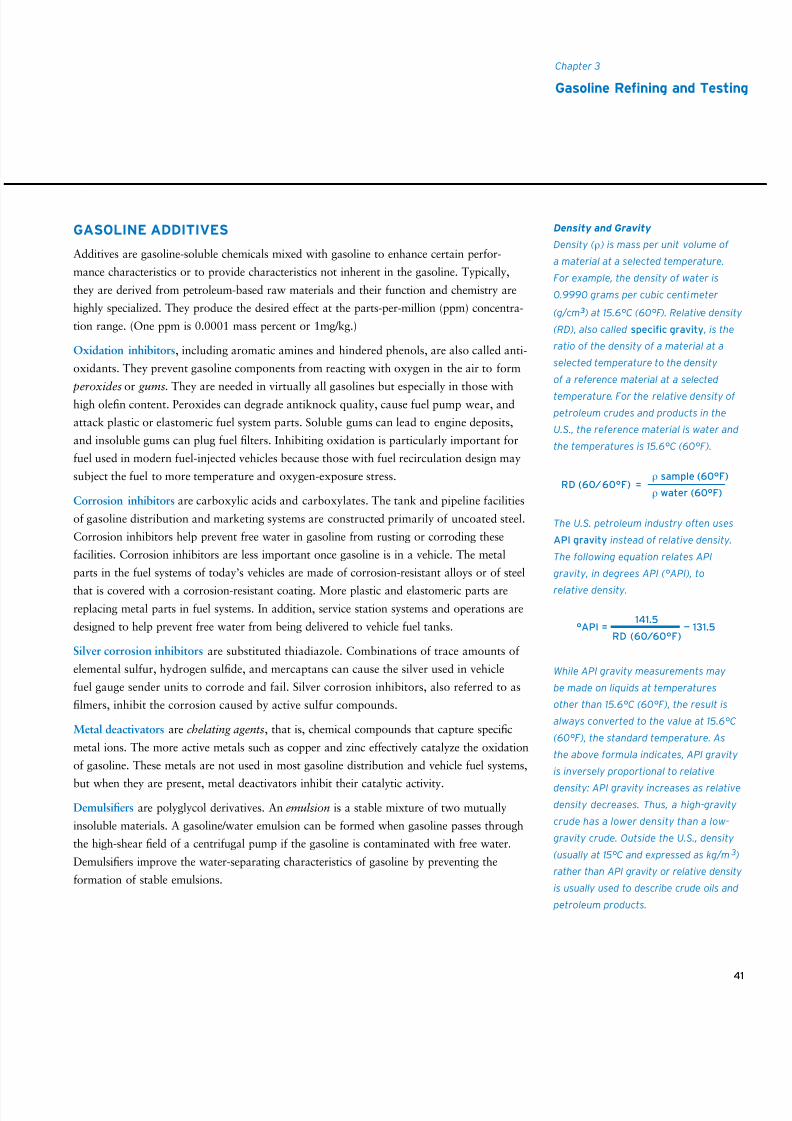
8/9/2019 AAAAAAAA MotorGas Tech Review
http://slidepdf.com/reader/full/aaaaaaaa-motorgas-tech-review 49/124
41
Chapter 3
Gasoline Rening and Testing
GASOLINE ADDITIVES
Additives are gasoline-soluble chemicals mixed with gasoline to enhance certain perfor-
mance characteristics or to provide characteristics not inherent in the gasoline. Typically,
they are derived from petroleum-based raw materials and their function and chemistry are
highly specialized. They produce the desired effect at the parts-per-million (ppm) concentra-
tion range. (One ppm is 0.0001 mass percent or 1mg/kg.)
Oxidation inhibitors, including aromatic amines and hindered phenols, are also called anti-
oxidants. They prevent gasoline components from reacting with oxygen in the air to form
peroxides or gums. They are needed in virtually all gasolines but especially in those withhigh olefin content. Peroxides can degrade antiknock quality, cause fuel pump wear, and
attack plastic or elastomeric fuel system parts. Soluble gums can lead to engine deposits,
and insoluble gums can plug fuel filters. Inhibiting oxidation is particularly important for
fuel used in modern fuel-injected vehicles because those with fuel recirculation design may
subject the fuel to more temperature and oxygen-exposure stress.
Corrosion inhibitors are carboxylic acids and carboxylates. The tank and pipeline facilities
of gasoline distribution and marketing systems are constructed primarily of uncoated steel.
Corrosion inhibitors help prevent free water in gasoline from rusting or corroding these
facilities. Corrosion inhibitors are less important once gasoline is in a vehicle. The metal
parts in the fuel systems of today’s vehicles are made of corrosion-resistant alloys or of steel
that is covered with a corrosion-resistant coating. More plastic and elastomeric parts are
replacing metal parts in fuel systems. In addition, service station systems and operations are
designed to help prevent free water from being delivered to vehicle fuel tanks.
Silver corrosion inhibitors are substituted thiadiazole. Combinations of trace amounts of
elemental sulfur, hydrogen sulfide, and mercaptans can cause the silver used in vehicle
fuel gauge sender units to corrode and fail. Silver corrosion inhibitors, also referred to as
filmers, inhibit the corrosion caused by active sulfur compounds.
Metal deactivators are chelating agents, that is, chemical compounds that capture specific
metal ions. The more active metals such as copper and zinc effectively catalyze the oxidation
of gasoline. These metals are not used in most gasoline distribution and vehicle fuel systems,
but when they are present, metal deactivators inhibit their catalytic activity.
Demulsifiers are polyglycol derivatives. An emulsion is a stable mixture of two mutually
insoluble materials. A gasoline/water emulsion can be formed when gasoline passes through
the high-shear field of a centrifugal pump if the gasoline is contaminated with free water.
Demulsifiers improve the water-separating characteristics of gasoline by preventing the
formation of stable emulsions.
Density and Gravity
Density ( ρ ) is mass per unit volume of
a material at a selected temperature.
For example, the density of water is
0.9990 grams per cubic centimeter
(g/cm 3 ) at 15.6°C (60°F). Relative density
(RD), also called specific gravity , is the
ratio of the density of a material at a
selected temperature to the density
of a reference material at a selected
temperature. For the relative density of
petroleum crudes and products in the
U.S., the reference material is water and
the temperatures is 15.6°C (60°F).
The U.S. petroleum industry often uses
API gravity instead of relative density.
The following equation relates API
gravity, in degrees API (°API), to
relative density.
While API gravity measurements may
be made on liquids at temperatures
other than 15.6°C (60°F), the result is
always converted to the value at 15.6°C
(60°F), the standard temperature. As
the above formula indicates, API gravity
is inversely proportional to relative
density: API gravity increases as relative
density decreases. Thus, a high-gravity
crude has a lower density than a low-
gravity crude. Outside the U.S., density
(usually at 15°C and expressed as kg/m 3 )
rather than API gravity or relative density
is usually used to describe crude oils and
petroleum products.
RD (60⁄ 60°F) =ρ sample (60°F)
ρ water (60°F)
°API = — 131.5141.5
RD (60⁄60°F)
8/9/2019 AAAAAAAA MotorGas Tech Review
http://slidepdf.com/reader/full/aaaaaaaa-motorgas-tech-review 50/124
42
Antiknock compounds increase the antiknock quality of gasoline. They include
materials based on:
• Lead alkyls, such as tetraethyl lead (TEL) and tetramethyl lead (TML)
• Manganese, called methylcyclopentadienyl manganese tricarbonyl (MMT)
• Iron, called ferrocene
Because only a small amount of additive is needed, using antiknock compounds is a
lower-cost method to increase octane number than changing gasoline chemistry.
Gasoline containing TEL was first marketed in 1923. The average concentration of leadin gasoline gradually was increased until it reached a maximum of about 660 milligrams
per liter (mg/L) or 2.5 grams per gallon (g/gal) in the late 1960s. After that, a series of
events resulted in the use of less lead. First, new refining processes produced higher-octane
gasoline components. Then, the population of vehicles that require unleaded gasoline –
those with catalytic exhaust emission controls – steadily grew. Last, U.S. EPA regulations
required the reduction of the lead content of gasoline in phased steps beginning in 1979.
The U.S. EPA completely banned the addition of lead additives to on-road gasoline in
1996. Currently, the amount of incidental lead may not exceed 13.2 mg/L (0.05 g/gal)
and cannot be deliberately added.
MMT was commercialized in 1959 and was used in gasoline alone or in combination
with lead alkyls. The U.S. Clean Air Act Amendments of 1977 banned the use of manga-
nese antiknock additives in unleaded gasoline unless the U.S. EPA granted a waiver.
MMT continued to be extensively used in unleaded gasoline in Canada at concentrations
up to 18 mg/L (0.068 g/gal) until 2004 when it was voluntarily removed. In 1996, after
several waiver requests and court actions by the manufacturer, the courts ordered the U.S.
EPA to grant a waiver for MMT. Its use is limited to a maximum of 8.2 mg/L (0.031 g/gal).
California regulations continue to ban the addition of manganese to gasoline.
MMT’s future in the U.S. is clouded. Its use in gasoline is opposed by environmental groups
and automobile manufacturers. Gasoline containing MMT leaves significant red-orange
deposits on spark plugs, catalytic converters, oxygen sensors, and combustion chamber
walls. The additive manufacturer has developed a large body of data to help support its
claim that MMT in gasoline does not reduce performance or increase emissions.
However, auto manufacturers have expressed concerns about shortened catalyst, oxygen
sensor, and spark plug life and interference with on-board diagnostic (OBD) system
performance (see page 72). In an auto industry test involving a large number of vehicles,
fuel containing MMT was shown to increase HC emissions in exhaust. Increases in other
emissions were observed at high mileages in some vehicles designed to meet low-emission
8/9/2019 AAAAAAAA MotorGas Tech Review
http://slidepdf.com/reader/full/aaaaaaaa-motorgas-tech-review 51/124
43
Chapter 3
Gasoline Rening and Testing
limits. In addition, there have been reports of plugging of high-density honeycomb mono-
lith catalyst systems on vehicles operating on gasoline containing MMT. Nevertheless, the
additive manufacturer takes exception to the auto manufacturers’ test results and their
concerns over catalyst plugging. Some new vehicle owner’s manuals recommend against
using gasoline containing MMT. Very little MMT is being used in gasoline sold in the U.S
at this time.
In many parts of the world, lead antiknocks are being eliminated from gasoline used
in vehicles that do not have catalytic exhaust emission controls and therefore do not
require unleaded gasoline. This grade of lead-free gasoline frequently is referred to as lead
replacement petrol (LRP), and it may contain a special additive to help protect engines
susceptible to exhaust-valve recession. However, refineries that do not have the processing
capability to produce the required octane quality without an antiknock additive may
use MMT because it can enhance octane quality and provide some protection against
exhaust-valve recession. The auto industry also opposes the use of MMT in this gasoline
because of concern that LRP may find its way into catalyst-equipped vehicles. To help
prevent misfueling, gas stations usually dispense LRP through gas pumps with nozzles
that are wider than the fuel tank openings on catalyst-equipped vehicles.
Ferrocene (dicyclopentadienyl iron) has been around for nearly 50 years. It has not been
widely marketed as an antiknock compound, although it has seen limited use in Europe.
When combusted, it forms ferric oxides (also known as jeweler’s rouge), a fine abrasive.Early studies of ferrocene showed excessive piston ring, cylinder bore, and camshaft
engine wear at the concentrations investigated. Recent auto industry studies involving
lower iron concentrations have shown premature spark plug failures at the current
recommended concentration of 30 ppm ferrocene (9 ppm iron). Concern also has been
expressed that ferric oxide will act as a physical barrier on oxygen sensors and exhaust
catalyst surfaces and possibly cause catalyst plugging in modern vehicles. In the U.S.,
ferrocene cannot be used in RFG because of a ban on the use of heavy metals. Further, it
cannot be used in conventional gasoline without obtaining a waiver from the U.S. EPA.
Deposit control additives See Chapter 6, “Gasoline Vehicles – Deposit Control.”
Anti-icing additives are surfactants, alcohols, and glycols. They prevent ice formation in
the carburetor and fuel system (see page 4). The need for this additive is disappearing as
older-model vehicles with carburetors are replaced by vehicles with fuel injection systems.
Dyes are oil-soluble solids and liquids used to visually distinguish batches, grades, or
applications of gasoline products. For example, gasoline for general aviation, which is
manufactured to unique and exacting requirements, is dyed blue to distinguish it from
motor gasoline.
8/9/2019 AAAAAAAA MotorGas Tech Review
http://slidepdf.com/reader/full/aaaaaaaa-motorgas-tech-review 52/124
44
Markers are a means of distinguishing specific batches of gasoline without providing an
obvious visual clue. A refiner may add a marker to its gasoline so it can be identified as it
moves through the distribution system.
Drag reducers are high-molecular-weight polymers that improve the fluid flow charac-
teristics of low-viscosity petroleum products. As energy costs have increased, pipelines
have sought more efficient ways to ship products. Drag reducers lower pumping costs by
reducing friction between flowing gasoline and pipe walls.
SPECIFICATIONS
It has been critical to the successful development of gasoline and gasoline-powered vehicles
to have consensus among refiners, vehicle manufacturers, and other interested parties on
the characteristics of gasoline necessary for satisfactory performance and reliable operation.
This consensus is reached in the U.S. under the auspices of ASTM International (formerly
the American Society for Testing and Materials). Many countries prescribe gasoline specifi-
cations that control properties similar to those specified in ASTM D4814. For instance, in
Canada, the Canadian General Standards Board (CGSB) functions like ASTM International
and issues CGSB 3.5-2004 for unleaded gasoline and CGSB 3.511-2005 for ethanol blends.
The Comité Européen de Normalisation (CEN, also known as the European Committee for
Standardization) issues specifications that are translated by country, including BS EN 228
(UK), NF EN 228 (France), DIN EN 228 (Germany), DS/EN 228 (Denmark), NS-EN 228
(Norway), and UNI EN 228 (Italy). The Japan Standards Association (JSA) issues gasoline
specification JIS K 2202 and test methods. Test methods in Europe are supported by CEN,
the International Organization for Standardization (ISO), and national institutes such as
Deutsches Institut für Normung (DIN, of Germany), L’Association Française de
Normalisation (AFNOR, of France), and BSI British Standards.
ASTM International Committee D02 on Petroleum Products and Lubricants is responsible
for gasoline specifications and test methods. A large number of groups are interested in or
affected by the specifications. Their viewpoints are brought to the D02 forum by represen-
tatives who also are members of ASTM International, including:
• Individual refiners
• API, an association of petroleum refiners
• Petroleum marketing organizations
• Pipeline companies
• Vehicle and engine manufacturers
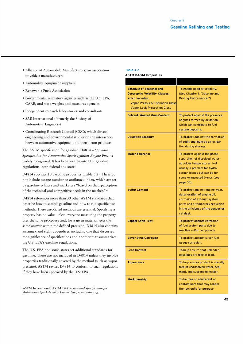
8/9/2019 AAAAAAAA MotorGas Tech Review
http://slidepdf.com/reader/full/aaaaaaaa-motorgas-tech-review 53/124
45
Chapter 3
Gasoline Rening and Testing
2 ASTM International, ASTM D4814 Standard Specification forAutomotive Spark-Ignition Engine Fuel, www.astm.org.
• Alliance of Automobile Manufacturers, an association
of vehicle manufacturers
• Automotive equipment suppliers
• Renewable Fuels Association
• Governmental regulatory agencies such as the U.S. EPA,
CARB, and state weights-and-measures agencies
• Independent research laboratories and consultants
• SAE International (formerly the Society ofAutomotive Engineers)
• Coordinating Research Council (CRC), which directs
engineering and environmental studies on the interaction
between automotive equipment and petroleum products
The ASTM specification for gasoline, D4814 – Standard
Specification for Automotive Spark-Ignition Engine Fuel , is
widely recognized. It has been written into U.S. gasoline
regulations, both federal and state.
D4814 specifies 10 gasoline properties (Table 3.2). These do
not include octane number or antiknock index, which are setby gasoline refiners and marketers “based on their perception
of the technical and competitive needs in the market.”2
D4814 references more than 30 other ASTM standards that
describe how to sample gasoline and how to run specific test
methods. These associated methods are essential. Specifying a
property has no value unless everyone measuring the property
uses the same procedure and, for a given material, gets the
same answer within the defined precision. D4814 also contains
an annex and eight appendices, including one that discusses
the significance of specifications and another that summarizes
the U.S. EPA’s gasoline regulations.
The U.S. EPA and some states set additional standards for
gasoline. These are not included in D4814 unless they involve
properties traditionally covered by the method (such as vapor
pressure). ASTM revises D4814 to conform to such regulations
if they have been approved by the U.S. EPA.
Table 3.2
ASTM D4814 Properties
Property
Schedule of Seasonal and
Geographic Volatility Classes,
which includes:
Vapor Pressure/Distillation Class
Vapor Lock Protection Class
Solvent-Washed Gum Content
Oxidation Stability
Water Tolerance
Sulfur Content
Copper Strip Test
Silver Strip Corrosion
Lead Content
Appearance
Workmanship
Intent
To enable good driveability.
(See Chapter 1, “Gasoline and
Driving Performance.”)
To protect against the presence
of gums formed by oxidation,which can contribute to fuel
system deposits.
To protect against the formation
of additional gum by air oxida-
tion during storage.
To protect against the phase
separation of dissolved water
at colder temperatures. Not
usually a problem for hydro-
carbon blends but can be for
some oxygenated blends (see
page 58).
To protect against engine wear,
deterioration of engine oil,
corrosion of exhaust system
parts and a temporary reduction
in the efficiency of the converter
catalyst.
To protect against corrosion
of fuel system parts due to
reactive sulfur compounds.
To protect against silver fuel
gauge corrosion.
To help ensure that unleaded
gasolines are free of lead.
To help ensure product is visually
free of undissolved water, sedi-
ment, and suspended matter.
To be free of adulterant or
contaminant that may render
the fuel unfit for purpose.
8/9/2019 AAAAAAAA MotorGas Tech Review
http://slidepdf.com/reader/full/aaaaaaaa-motorgas-tech-review 54/124
46
Each gasoline refiner, each pipeline that ships gasoline, some states, and even automobile
manufacturers may set additional internal specifications beyond ASTM D4814 or may
set more or less stringent limits for the D4814 properties. However, except in the case
of internal refining specifications, these limits will not prevail unless all interested parties
recognize their value.
The U.S. federal government and the state of California set limits on RFG to help
control emissions and specify approved test methods to determine compliance.
Terminology, requirements, test methods, applicable areas, and discussion of RFG
for both U.S. and California programs are summarized in ASTM Research Report
D02:1347 – Research Report on Reformulated Spark-Ignition Engine Fuel.
Table 3.3 contains a list of the test methods approved for determining motor
gasoline properties.
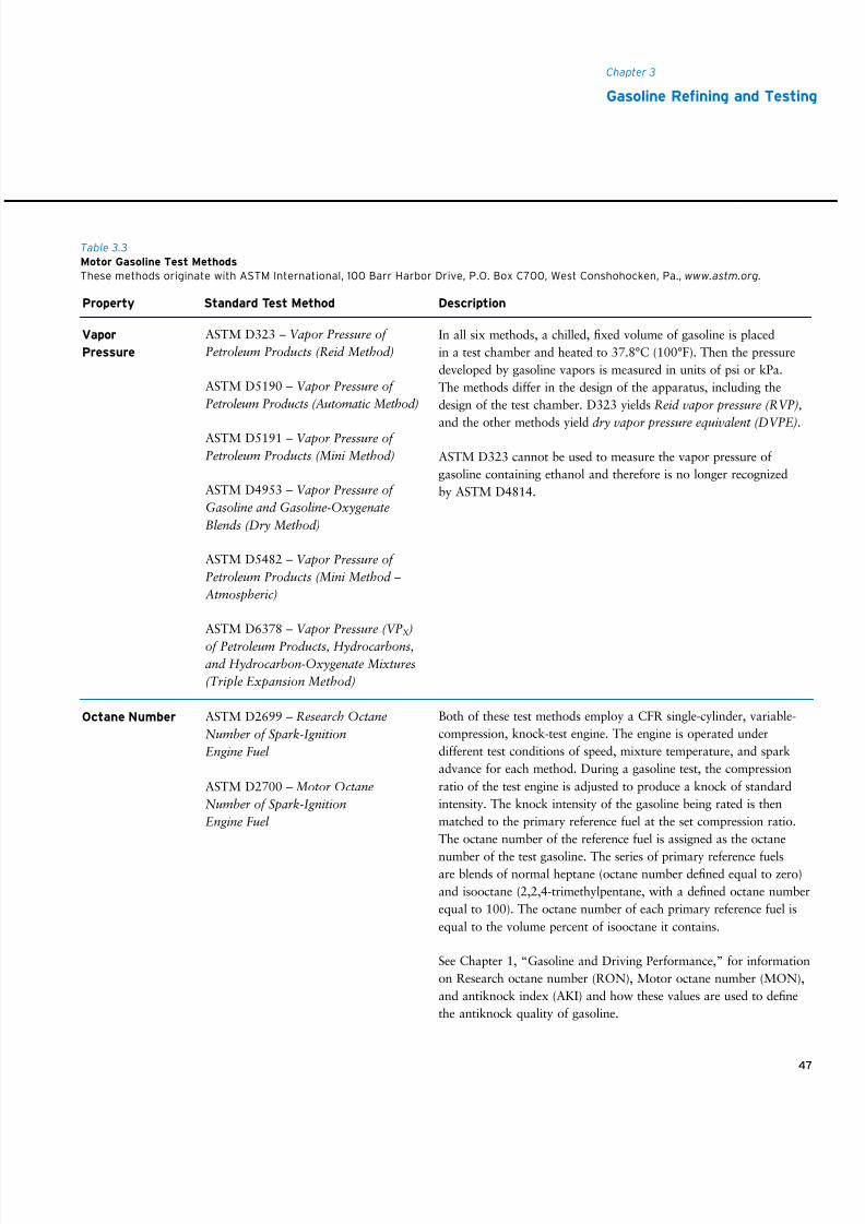
8/9/2019 AAAAAAAA MotorGas Tech Review
http://slidepdf.com/reader/full/aaaaaaaa-motorgas-tech-review 55/124
47
Chapter 3
Gasoline Rening and Testing
ASTM D323 – Vapor Pressure of
Petroleum Products (Reid Method)
ASTM D5190 – Vapor Pressure of
Petroleum Products (Automatic Method)
ASTM D5191 – Vapor Pressure of
Petroleum Products (Mini Method)
ASTM D4953 – Vapor Pressure of
Gasoline and Gasoline-Oxygenate
Blends (Dry Method)
ASTM D5482 – Vapor Pressure of
Petroleum Products (Mini Method –
Atmospheric)
ASTM D6378 – Vapor Pressure (VPX )
of Petroleum Products, Hydrocarbons,and Hydrocarbon-Oxygenate Mixtures
(Triple Expansion Method)
ASTM D2699 – Research Octane
Number of Spark-Ignition
Engine Fuel
ASTM D2700 – Motor Octane
Number of Spark-Ignition
Engine Fuel
In all six methods, a chilled, fixed volume of gasoline is placed
in a test chamber and heated to 37.8°C (100°F). Then the pressure
developed by gasoline vapors is measured in units of psi or kPa.
The methods differ in the design of the apparatus, including the
design of the test chamber. D323 yields Reid vapor pressure (RVP),
and the other methods yield dry vapor pressure equivalent (DVPE).
ASTM D323 cannot be used to measure the vapor pressure of
gasoline containing ethanol and therefore is no longer recognized
by ASTM D4814.
Both of these test methods employ a CFR single-cylinder, variable-
compression, knock-test engine. The engine is operated under
different test conditions of speed, mixture temperature, and spark
advance for each method. During a gasoline test, the compression
ratio of the test engine is adjusted to produce a knock of standard
intensity. The knock intensity of the gasoline being rated is then
matched to the primary reference fuel at the set compression ratio.
The octane number of the reference fuel is assigned as the octane
number of the test gasoline. The series of primary reference fuelsare blends of normal heptane (octane number defined equal to zero)
and isooctane (2,2,4-trimethylpentane, with a defined octane number
equal to 100). The octane number of each primary reference fuel is
equal to the volume percent of isooctane it contains.
See Chapter 1, “Gasoline and Driving Performance,” for information
on Research octane number (RON), Motor octane number (MON),
and antiknock index (AKI) and how these values are used to define
the antiknock quality of gasoline.
Vapor
Pressure
Octane Number
Property Standard Test Method Description
Table 3.3
Motor Gasoline Test Methods
These methods originate with ASTM International, 100 Barr Harbor Drive, P.O. Box C700, West Conshohocken, Pa., www.astm.org.
8/9/2019 AAAAAAAA MotorGas Tech Review
http://slidepdf.com/reader/full/aaaaaaaa-motorgas-tech-review 56/124
4848
ASTM D86 – Distillation of
Petroleum Products at Atmospheric
Pressure
Generally, road octane number (RdON) is determined by the
CRC’s Modified Uniontown Technique F-28-651. In this procedure,
a test vehicle is operated on a series of primary reference fuels of
increasing octane number under maximum throttle acceleration.
(This test cannot be run on modern vehicles that have timing regu-
lated by engine control modules [see page 72].) The basic timing
is advanced for each reference fuel until trace knock – the lowest
knock level detected by the ear of the person rating the fuel – is
detected. The plot of basic spark timing vs. RON provides a primaryreference curve for the test car. Then the car is operated on the
gasoline to be rated until the spark advance needed to cause trace
knock under maximum throttle acceleration is found. The octane
number associated with that spark timing advance in the primary
reference curve is the RdON of the test gasoline.
For a statistically significant determination, 10 to 15 test vehicles
(usually different models) must be used because of the numerous
variables involved. The RdONs of the individual vehicles are aver-
aged to determine the final RdON of the test gasoline.
In this test, a 100-milliliter fuel sample is placed in a round-bottom
flask and heated to a controlled rate of evaporation. The tempera-
ture is recorded when the first drop of condensate falls from the
lower end of the condenser tube into the receiving cylinder (the
initial boiling point) and then at recovered volume percentages of
5 percent, 10 percent, every increment of 10 percent to 90 percent,
95 percent, and at the end of the test (end point/final boiling point).
For gasoline samples, it is possible to correct for any sample loss
by converting the temperatures associated with each incremental
volume percentage recovered to temperatures for each incremental
volume percentage evaporated.
Property Standard Test Method Description
Road Octane
Number
Distillation
Prole
8/9/2019 AAAAAAAA MotorGas Tech Review
http://slidepdf.com/reader/full/aaaaaaaa-motorgas-tech-review 57/124
49
Property Standard Test Method Description
Chapter 3
Gasoline Rening and Testing
ASTM D5188 – Vapor-Liquid Ratio
Temperature Determination of Fuels
(Evacuated Chamber Method)
ASTM D1298 – Density, Relative
Density (Specific Gravity), or API
Gravity of Crude Petroleum and
Liquid Petroleum Products by
Hydrometer Method
ASTM D4052 – Density and
Relative Density of Liquids by
Digital Density Meter
ASTM D525 – Oxidation Stability of
Gasoline (Induction Period Method)
ASTM D381 – Gum Content in
Fuels by Jet Evaporation
In D5188, a calculated volume of air-saturated sample (all fuels)
at 0°C (32°F) is introduced into an evacuated, thermostatically
controlled test chamber of known volume. The sample volume is
calculated to obtain the desired V/L ratio in the chamber. After
injection, the chamber temperature is adjusted until a stable
chamber pressure of 101.3 kPa (760 mm Hg) is achieved.
ASTM D4814, Appendix X2 – Two calculation methods are
specified: a computer method and a linear equation method. Thesemethods are used to estimate vapor-liquid ratio (V/L) from vapor
pressure and distillation test results and are not applicable for
oxygenated gasolines. A procedure for correcting the estimated V/L
values for ethanol blends is now part of D4814.
For D1298, the sample is placed in a cylinder and the appropriate
hydrometer is lowered into the sample. After temperature equilib-
rium has been reached, the sample temperature and hydrometer
scale reading are recorded. ASTM Petroleum Measurement Tables
are used to convert the recorded value to the value at a standard
temperature such as 15°C or 60°F.
For D4052, a small volume of liquid sample is introduced into an
oscillating sample tube, and the change in oscillating frequency
caused by the change in the mass of the tube is used in conjunction
with calibration data to determine the density of the sample.
Fifty milliliters of gasoline are placed in a glass sample container
in a pressure vessel. Oxygen is introduced to a pressure of about
700 kPa (100 psi). The charged pressure vessel is placed in a 100°C
(212°F) bath, and the pressure is continuously monitored. The
break point of the fuel is determined to be the point just prior to a
specified drop in pressure within a 15-minute interval. The number
of minutes to the break point is reported.
Fifty milliliters of gasoline are evaporated under controlled air flow
at about 155°C (310°F) for 30 minutes. The residue is weighed
before and after extraction with n-heptane. The result is reported as
milligrams per 100 mL.
Vapor-Liquid
Ratio
API Gravity
(see page 41)
Oxidation
Stability
(Induction
Period)
Solvent-Washed
Gum Content
8/9/2019 AAAAAAAA MotorGas Tech Review
http://slidepdf.com/reader/full/aaaaaaaa-motorgas-tech-review 58/124
50
Chevron’s test method for deter-
mining the gumming potential of a
gasoline is based on ASTM D873 –
Oxidation Stability of Aviation Fuels
(Potential Residue Method), which
combines ASTM D525 – Oxidation
Stability of Gasoline (Induction
Period Method) and ASTM D381 –
Gum Content in Fuels by JetEvaporation.
ASTM D1266 – Sulfur in Petroleum
Products (Lamp Method)
ASTM D2622 – Sulfur in Petroleum
Products by Wavelength Dispersive
X-ray Fluorescence Spectrometry
ASTM D3120 – Trace Quantities of
Sulfur in Light Liquid Hydrocarbons
by Oxidative Microcoulometry
ASTM D4045 – Sulfur in Petroleum
Products by Hydrogenolysis and
Rateometric Colorimetry
ASTM D4294 – Sulfur in Petroleum
and Petroleum Products by Energy-
Dispersive X-ray Fluorescence
Spectrometry
ASTM D5453 – Determination of
Total Sulfur in Light Hydrocarbons,
Spark Ignition Engine Fuel, Diesel
Engine Fuel, and Engine Oil by
Ultraviolet Fluorescence
ASTM D6334 – Sulfur in Gasoline
by Wavelength Dispersive X-Ray
Fluorescence
One hundred milliliters of gasoline, free of deposit control additive, is
oxidized for four hours at 100°C (212°F) in a bomb initially charged
with 700 kPa (100 psi) of oxygen. After this treatment, the amount
of insoluble gum is collected by filtration and measured. The soluble
gum is isolated by ASTM D381 and measured. The total insoluble
and soluble gum is reported as potential gum in units of milligrams
per 100 mL.
As the names of the sulfur test methods indicate, several technolo-
gies are used to determine the sulfur content of gasoline. Some
of the methods are applicable only for samples with high sulfur
concentration, others cover a broad range of sulfur concentration,
and some can be used only for samples with low sulfur concen-
tration. Specific test methods need to be reviewed for applicability
before selecting one to use.
Potential Gum
Sulfur Content
Property Standard Test Method Description
8/9/2019 AAAAAAAA MotorGas Tech Review
http://slidepdf.com/reader/full/aaaaaaaa-motorgas-tech-review 59/124
51
Chapter 3
Gasoline Rening and Testing
ASTM D6445 – Sulfur in Gasoline
by Energy-Dispersive X-ray
Fluorescence Spectrometry
ASTM D7039 – Sulfur in Gasoline
and Diesel Fuel by Monochromatic
Wavelength Dispersive X-ray
Fluorescence Spectrometry
ASTM D130 – Detection of Copper
Corrosion from Petroleum Products
by the Copper Strip Tarnish Test
ASTM D4814 Annex A1 –
Corrosiveness of Silver From
Petroleum Products by Silver
Strip Test
ASTM D3237 – Lead in Gasoline by
Atomic Absorption Spectroscopy
ASTM D5059 – Lead in Gasoline by
X-Ray Spectroscopy
D130 can be used to detect the presence of free sulfur or reactive
sulfur compounds. In this test, a polished copper strip is immersed in
30 milliliters of gasoline and heated to 50°C (122°F) for three hours.
The test strip is compared to standard strips and reported on a scale
of one to four (one being best).
It is becoming clear that as sulfur levels in gasolines are forced lower,
many sulfur species that actually provide protection for copper
surfaces are being greatly reduced or eliminated. In reformulated
gasolines that have extremely low sulfur content, levels of free sulfur
or reactive sulfur compounds that would not have caused a failed
copper strip test in conventional gasolines may now cause a failure.
This factor increases the urgency for minimizing contamination with
even minor levels of free sulfur or reactive sulfur compounds in
processing at the refinery.
This interim test method uses the ASTM D130 test apparatus
except a silver coupon replaces the normal copper one and the test
is conducted at 37.8°C (100°F) for three hours.
These methods are applicable for determining the low levels of lead
that may be present in unleaded gasoline.
Sulfur Content
Copper Strip
Corrosion
Silver Strip
Corrosion
Lead Content
Property Standard Test Method Description
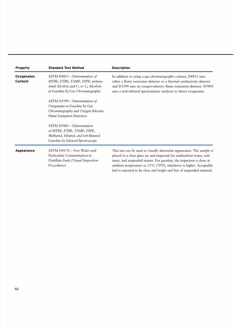
8/9/2019 AAAAAAAA MotorGas Tech Review
http://slidepdf.com/reader/full/aaaaaaaa-motorgas-tech-review 60/124
52
ASTM D4815 – Determination of
MTBE, ETBE, TAME, DIPE, tertiary-
Amyl Alcohol, and C1 to C4 Alcohols
in Gasoline by Gas Chromatography
ASTM D5599 – Determination of
Oxygenates in Gasoline by Gas
Chromatography and Oxygen Selective
Flame Ionization Detection
ASTM D5845 – Determination
of MTBE, ETBE, TAME, DIPE,
Methanol, Ethanol, and tert-Butanol
Gasoline by Infrared Spectroscopy
ASTM D4176 – Free Water and
Particulate Contamination in
Distillate Fuels (Visual Inspection
Procedures)
In addition to using a gas chromatography column, D4815 uses
either a flame ionization detector or a thermal conductivity detector
and D5599 uses an oxygen-selective flame ionization detector. D5845
uses a mid-infrared spectrometric analyzer to detect oxygenates.
This test can be used to visually determine appearance. The sample is
placed in a clear glass jar and inspected for undissolved water, sedi-
ment, and suspended matter. For gasoline, the inspection is done at
ambient temperature or 21°C (70°F), whichever is higher. Acceptable
fuel is reported to be clear and bright and free of suspended material.
Oxygenates
Content
Appearance
Property Standard Test Method Description
8/9/2019 AAAAAAAA MotorGas Tech Review
http://slidepdf.com/reader/full/aaaaaaaa-motorgas-tech-review 61/124
53
Oxygenated gasoline is not new; oxygenates have been added to gasoline for decades. Prior
to 2006, methyl tertiary butyl ether (MTBE) and tertiary amyl methyl ether (TAME) along
with smaller quantities of ethyl tertiary butyl ether (ETBE) were used in U.S. gasoline.
Today, ethanol, also called ethyl alcohol or grain alcohol , is used almost exclusively.
Widespread use of ethanol in the United States began in 1978 when a Nebraska group
marketed gasoline containing 10 volume percent ethanol as gasohol . The program was
intended to help increase gasoline availability during the energy crisis of that decade.
Later, the gasohol name was abandoned, but the use of ethanol continued. Much of the
early ethanol-blended product was marketed in the Midwestern states, where the bulk of
ethanol is produced.
In the 1990s, air quality regulations required gasolines in some parts of the United States
to be oxygenated either in the winter or else year-round. (See page 27 for information
regarding gasolines in carbon monoxide [CO] nonattainment areas and Federal Phase I
and California Phase 2 reformulated gasolines [RFG].) By 2001, about 10 percent of all
the gasoline sold in the U.S. contained ethanol and 58 percent of the blends contained
10 volume percent ethanol, often referred to as E10. Initially, little RFG contained ethanol.
As noted in Chapter 3, “Gasoline Refining and Testing,” MTBE was used as an oxygenate
to meet U.S. Environmental Protection Agency (EPA) and California Air Resources Board
(CARB) reformulation requirements. The first U.S. EPA waiver for MTBE use was
issued in 1979 for 7.0 volume percent, and a second waiver for 15.0 volume percent wasissued in 1988. MTBE was not widely used until the late 1980s, and then its use expanded
with the introduction of federal RFG in 1995. California banned the use of MTBE and
other ethers and heavy alcohols as of January 1, 2004. A number of other states followed
California’s lead, which greatly diminished MTBE use. In 2006, the U.S. EPA rescinded
the oxygenated gasoline requirement in federal RFG, as required by the Energy Policy
Act of 2005. This resulted in the removal of virtually all MTBE from the U.S. gasoline
pool. Gasoline refiners in the U.S. ceased using MTBE, and by default, ethanol became the
oxygenate component used almost exclusively.
CHEMISTRY
Oxygenated gasoline is a mixture of conventional hydrocarbon-based gasoline and one
or more oxygenates. Oxygenates are combustible liquids made up of carbon, hydrogen,
and oxygen. All the oxygenates currently used in gasoline belong to one of two classes
of organic molecules: alcohols and ethers.1 In alcohols, a hydrocarbon group and a
hydrogen atom are bonded to an oxygen atom: R-O-H, where R represents the hydro-
53
4 • Oxygenated Gasoline
1 The word ether reminds many people of the anesthetic. Although the anesthetic commonly is called
ether, its chemical name is diethyl ether (CH3CH
2OCH
2CH
3). It is not used as a gasoline oxygenate
because it is too volatile.
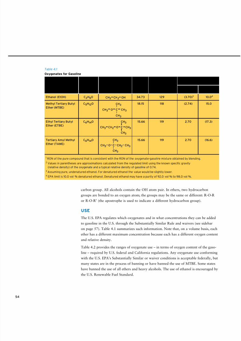
8/9/2019 AAAAAAAA MotorGas Tech Review
http://slidepdf.com/reader/full/aaaaaaaa-motorgas-tech-review 62/124
54
carbon group. All alcohols contain the OH atom pair. In ethers, two hydrocarbon
groups are bonded to an oxygen atom; the groups may be the same or different: R-O-R
or R-O-R’ (the apostrophe is used to indicate a different hydrocarbon group).
USE
The U.S. EPA regulates which oxygenates and in what concentrations they can be added
to gasoline in the U.S. through the Substantially Similar Rule and waivers (see sidebar
on page 57). Table 4.1 summarizes such information. Note that, on a volume basis, each
ether has a different maximum concentration because each has a different oxygen content
and relative density.
Table 4.2 provides the ranges of oxygenate use – in terms of oxygen content of the gaso-
line – required by U.S. federal and California regulations. Any oxygenate use conforming
with the U.S. EPA’s Substantially Similar or waiver conditions is acceptable federally, but
many states are in the process of banning or have banned the use of MTBE. Some states
have banned the use of all ethers and heavy alcohols. The use of ethanol is encouraged by
the U.S. Renewable Fuel Standard.
Ethanol (EtOH) C2H6O 34.73 129 (3.70)3 10.04
Methyl Tertiary Butyl C5H12O 18.15 118 (2.74) 15.0
Ether (MTBE)
Ethyl Tertiary Butyl C6H14O 15.66 119 2.70 (17.3)
Ether (ETBE)
Tertiary Amyl Methyl C6H14O 15.66 119 2.70 (16.6)
Ether (TAME)
Table 4.1
Oxygenates for Gasoline
1 RON of the pure compound that is consistent with the RON of the oxygenate-gasoline mixture obtained by blending.2 Values in parentheses are approximations calculated from the regulated limit using the known specic gravity
(relative density) of the oxygenate and a typical relative density of gasoline of 0.74.3 Assuming pure, undenatured ethanol. For denatured ethanol the value would be slightly lower.4 EPA limit is 10.0 vol % denatured ethanol. Denatured ethanol may have a purity of 92.0 vol % to 98.0 vol %.
C
CH3
CH3
CH3CH3 CH2 O
CO
CH3
CH3
CH3 CH3CH2
C
CH3
CH3
CH3 CH3O
Oxygen Blending
Content Research Octane Mass % Volume %
Name Formula Structure Mass % Number (BRON)1 Oxygen Oxygenate
Maximum Concentration
Approved by EPA2
CH3 CH2 OH
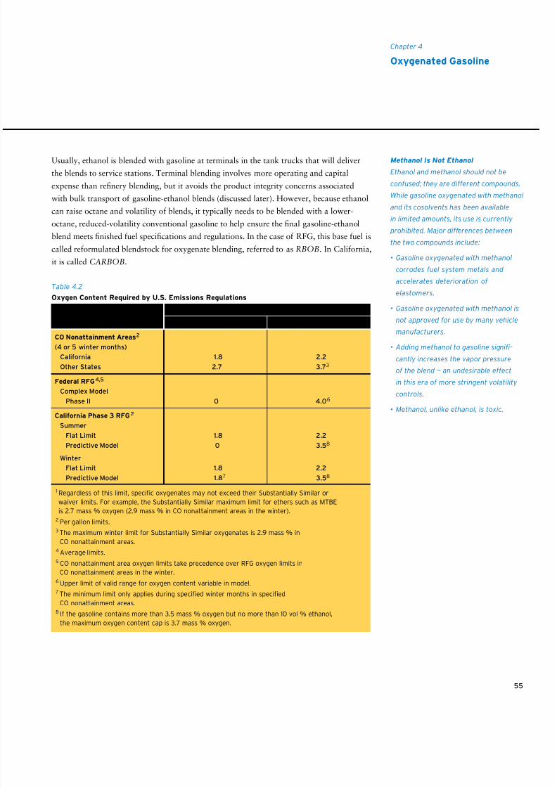
8/9/2019 AAAAAAAA MotorGas Tech Review
http://slidepdf.com/reader/full/aaaaaaaa-motorgas-tech-review 63/124
55
Chapter 4
Oxygenated Gasoline
Usually, ethanol is blended with gasoline at terminals in the tank trucks that will deliver
the blends to service stations. Terminal blending involves more operating and capital
expense than refinery blending, but it avoids the product integrity concerns associated
with bulk transport of gasoline-ethanol blends (discussed later). However, because ethanol
can raise octane and volatility of blends, it typically needs to be blended with a lower-
octane, reduced-volatility conventional gasoline to help ensure the final gasoline-ethanol
blend meets finished fuel specifications and regulations. In the case of RFG, this base fuel is
called reformulated blendstock for oxygenate blending, referred to as RBOB. In California,
it is called CARBOB.
Methanol Is Not Ethanol
Ethanol and methanol should not be
confused; they are different compounds.
While gasoline oxygenated with methanol
and its cosolvents has been available
in limited amounts, its use is currently
prohibited. Major differences between
the two compounds include:
• Gasoline oxygenated with methanol
corrodes fuel system metals and
accelerates deterioration of
elastomers.
• Gasoline oxygenated with methanol is
not approved for use by many vehicle
manufacturers.
• Adding methanol to gasoline signi-
cantly increases the vapor pressure
of the blend — an undesirable effect
in this era of more stringent volatility
controls.
• Methanol, unlike ethanol, is toxic.
CO Nonattainment Areas2
(4 or 5 winter months)
California 1.8 2.2
Other States 2.7 3.73
Federal RFG4,5
Complex Model
Phase II 0 4.06
California Phase 3 RFG2
Summer
Flat Limit 1.8 2.2
Predictive Model 0 3.58
Winter
Flat Limit 1.8 2.2
Predictive Model 1.87 3.58
Table 4.2
Oxygen Content Required by U.S. Emissions Regulations
1 Regardless of this limit, specic oxygenates may not exceed their Substantially Similar or
waiver limits. For example, the Substantially Similar maximum limit for ethers such as MTBE
is 2.7 mass % oxygen (2.9 mass % in CO nonattainment areas in the winter).2 Per gallon limits.3 The maximum winter limit for Substantially Similar oxygenates is 2.9 mass % in
CO nonattainment areas.
4 Average limits.5 CO nonattainment area oxygen limits take precedence over RFG oxygen limits in
CO nonattainment areas in the winter.6 Upper limit of valid range for oxygen content variable in model.7 The minimum limit only applies during specied winter months in specied
CO nonattainment areas.8 If the gasoline contains more than 3.5 mass % oxygen but no more than 10 vol % ethanol,
the maximum oxygen content cap is 3.7 mass % oxygen.
Regulation Minimum Maximum1
Oxygen Content, Mass Percent
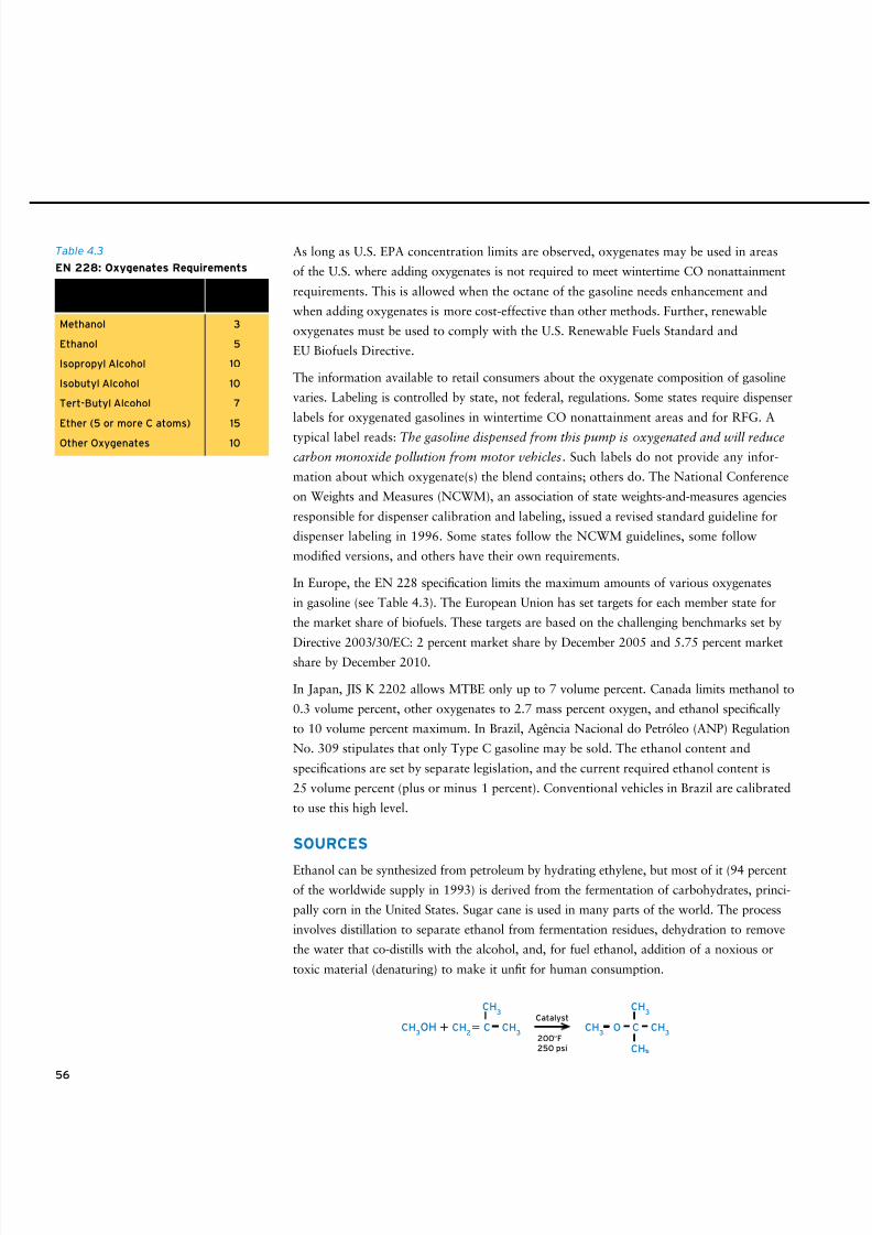
8/9/2019 AAAAAAAA MotorGas Tech Review
http://slidepdf.com/reader/full/aaaaaaaa-motorgas-tech-review 64/124
56
As long as U.S. EPA concentration limits are observed, oxygenates may be used in areas
of the U.S. where adding oxygenates is not required to meet wintertime CO nonattainment
requirements. This is allowed when the octane of the gasoline needs enhancement and
when adding oxygenates is more cost-effective than other methods. Further, renewable
oxygenates must be used to comply with the U.S. Renewable Fuels Standard and
EU Biofuels Directive.
The information available to retail consumers about the oxygenate composition of gasoline
varies. Labeling is controlled by state, not federal, regulations. Some states require dispenser
labels for oxygenated gasolines in wintertime CO nonattainment areas and for RFG. A
typical label reads: The gasoline dispensed from this pump is oxygenated and will reduce
carbon monoxide pollution from motor vehicles. Such labels do not provide any infor-
mation about which oxygenate(s) the blend contains; others do. The National Conference
on Weights and Measures (NCWM), an association of state weights-and-measures agencies
responsible for dispenser calibration and labeling, issued a revised standard guideline for
dispenser labeling in 1996. Some states follow the NCWM guidelines, some follow
modified versions, and others have their own requirements.
In Europe, the EN 228 specification limits the maximum amounts of various oxygenates
in gasoline (see Table 4.3). The European Union has set targets for each member state for
the market share of biofuels. These targets are based on the challenging benchmarks set by
Directive 2003/30/EC: 2 percent market share by December 2005 and 5.75 percent marketshare by December 2010.
In Japan, JIS K 2202 allows MTBE only up to 7 volume percent. Canada limits methanol to
0.3 volume percent, other oxygenates to 2.7 mass percent oxygen, and ethanol specifically
to 10 volume percent maximum. In Brazil, Agência Nacional do Petróleo (ANP) Regulation
No. 309 stipulates that only Type C gasoline may be sold. The ethanol content and
specifications are set by separate legislation, and the current required ethanol content is
25 volume percent (plus or minus 1 percent). Conventional vehicles in Brazil are calibrated
to use this high level.
SOURCES
Ethanol can be synthesized from petroleum by hydrating ethylene, but most of it (94 percent
of the worldwide supply in 1993) is derived from the fermentation of carbohydrates, princi-
pally corn in the United States. Sugar cane is used in many parts of the world. The process
involves distillation to separate ethanol from fermentation residues, dehydration to remove
the water that co-distills with the alcohol, and, for fuel ethanol, addition of a noxious or
toxic material (denaturing) to make it unfit for human consumption.
CH3OH CH
2 C CH
3
CH3
CH3 O C CH
3
CH3
CH
Catalyst
200°F250 psi
Table 4.3
EN 228: Oxygenates Requirements
Maximum
Oxygenate Vol %
Methanol 3
Ethanol 5
Isopropyl Alcohol 10
Isobutyl Alcohol 10
Tert-Butyl Alcohol 7
Ether (5 or more C atoms) 15
Other Oxygenates 10
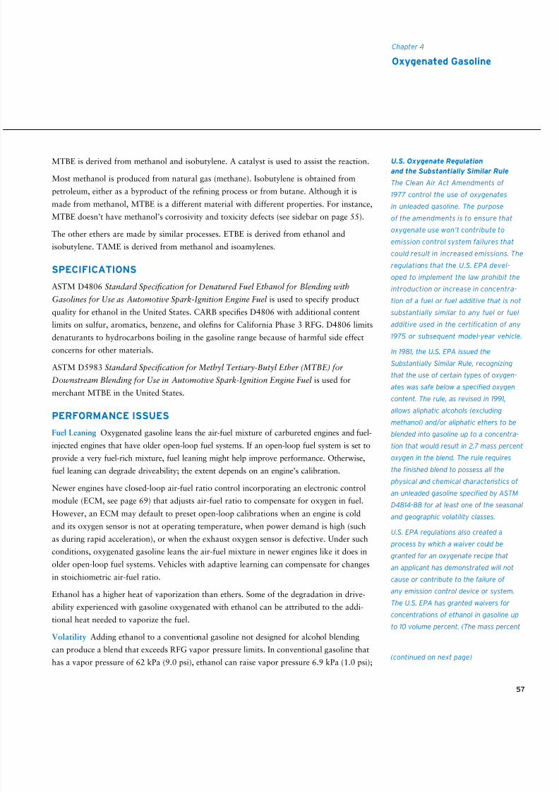
8/9/2019 AAAAAAAA MotorGas Tech Review
http://slidepdf.com/reader/full/aaaaaaaa-motorgas-tech-review 65/124
57
Chapter 4
Oxygenated Gasoline
MTBE is derived from methanol and isobutylene. A catalyst is used to assist the reaction.
Most methanol is produced from natural gas (methane). Isobutylene is obtained from
petroleum, either as a byproduct of the refining process or from butane. Although it is
made from methanol, MTBE is a different material with different properties. For instance,
MTBE doesn’t have methanol’s corrosivity and toxicity defects (see sidebar on page 55).
The other ethers are made by similar processes. ETBE is derived from ethanol and
isobutylene. TAME is derived from methanol and isoamylenes.
SPECIFICATIONS
ASTM D4806 Standard Specification for Denatured Fuel Ethanol for Blending with
Gasolines for Use as Automotive Spark-Ignition Engine Fuel is used to specify product
quality for ethanol in the United States. CARB specifies D4806 with additional content
limits on sulfur, aromatics, benzene, and olefins for California Phase 3 RFG. D4806 limits
denaturants to hydrocarbons boiling in the gasoline range because of harmful side effect
concerns for other materials.
ASTM D5983 Standard Specification for Methyl Tertiary-Butyl Ether (MTBE) for
Downstream Blending for Use in Automotive Spark-Ignition Engine Fuel is used for
merchant MTBE in the United States.
PERFORMANCE ISSUESFuel Leaning Oxygenated gasoline leans the air-fuel mixture of carbureted engines and fuel-
injected engines that have older open-loop fuel systems. If an open-loop fuel system is set to
provide a very fuel-rich mixture, fuel leaning might help improve performance. Otherwise,
fuel leaning can degrade driveability; the extent depends on an engine’s calibration.
Newer engines have closed-loop air-fuel ratio control incorporating an electronic control
module (ECM, see page 69) that adjusts air-fuel ratio to compensate for oxygen in fuel.
However, an ECM may default to preset open-loop calibrations when an engine is cold
and its oxygen sensor is not at operating temperature, when power demand is high (such
as during rapid acceleration), or when the exhaust oxygen sensor is defective. Under such
conditions, oxygenated gasoline leans the air-fuel mixture in newer engines like it does inolder open-loop fuel systems. Vehicles with adaptive learning can compensate for changes
in stoichiometric air-fuel ratio.
Ethanol has a higher heat of vaporization than ethers. Some of the degradation in drive-
ability experienced with gasoline oxygenated with ethanol can be attributed to the addi-
tional heat needed to vaporize the fuel.
Volatility Adding ethanol to a conventional gasoline not designed for alcohol blending
can produce a blend that exceeds RFG vapor pressure limits. In conventional gasoline that
has a vapor pressure of 62 kPa (9.0 psi), ethanol can raise vapor pressure 6.9 kPa (1.0 psi);
U.S. Oxygenate Regulation
and the Substantially Similar Rule
The Clean Air Act Amendments of
1977 control the use of oxygenates
in unleaded gasoline. The purpose
of the amendments is to ensure that
oxygenate use won’t contribute to
emission control system failures that
could result in increased emissions. The
regulations that the U.S. EPA devel-
oped to implement the law prohibit theintroduction or increase in concentra-
tion of a fuel or fuel additive that is not
substantially similar to any fuel or fuel
additive used in the certification of any
1975 or subsequent model-year vehicle.
In 1981, the U.S. EPA issued the
Substantially Similar Rule, recognizing
that the use of certain types of oxygen-
ates was safe below a specified oxygen
content. The rule, as revised in 1991,
allows aliphatic alcohols (excluding
methanol) and/or aliphatic ethers to be
blended into gasoline up to a concentra-
tion that would result in 2.7 mass percent
oxygen in the blend. The rule requires
the finished blend to possess all the
physical and chemical characteristics of
an unleaded gasoline specified by ASTM
D4814-88 for at least one of the seasonal
and geographic volatility classes.
U.S. EPA regulations also created a
process by which a waiver could be
granted for an oxygenate recipe that
an applicant has demonstrated will not
cause or contribute to the failure of
any emission control device or system.
The U.S. EPA has granted waivers for
concentrations of ethanol in gasoline up
to 10 volume percent. (The mass percent
(continued on next page)
8/9/2019 AAAAAAAA MotorGas Tech Review
http://slidepdf.com/reader/full/aaaaaaaa-motorgas-tech-review 66/124
58
in RBOB that has a vapor pressure of 39.6 kPa (5.7 psi), ethanol can raise vapor pressure
9.0 kPa (1.3 psi). This increase, coupled with the corresponding reduction in mid-range
distillation properties, lowers the V/L = 20 temperature, reducing vapor lock protection.
Blend volatility is increased only slightly by MTBE and not at all by ETBE and TAME.
Because it significantly increases fuel volatility, ethanol has not been the oxygenate
of choice for summer RFGs, which have very tight vapor pressure limits. Now, with
increasing use of ethanol, hydrocarbons with higher volatility must be removed during the
production of RBOB to help ensure the final gasoline-ethanol blend meets specifications
and complies with regulations.
Commingling , another volatility issue, can occur if ethanol-blended fuel is mixed with
hydrocarbon-only fuel in a vehicle fuel tank. In effect, the ethanol in the ethanol blend
increases the vapor pressure of the hydrocarbon-only gasoline. The increase in vapor
pressure is dependent on the ratio of the two components and the amount of ethanol in
the blend. The maximum effect of about 6.2 kPa (0.9 psi) increase occurs for a 5.7 volume
percent ethanol blend when the mixture contains about 75 percent hydrocarbon-only
gasoline where both fuels initially have a vapor pressure of 48.3 kPa (7.0 psi).
Water Tolerance Conventional gasoline, depending on its aromatics content, can dissolve
up to 150 parts per million (ppm) water at 21°C (70°F). Oxygenating gasoline with
ethers can increase water solubility to 600 ppm. Contacting either conventional gasoline
or ether-oxygenated gasoline with additional water will not affect the properties of thegasoline but can make it appear hazy.
Water-saturated blends become hazy when cooled because some of the water becomes
insoluble. However, the water that is released does not contain much ether, and the
blends do not contain enough water to cause performance problems.
The situation is different for gasoline oxygenated with 10 volume percent ethanol. The
gasoline-alcohol blend can dissolve more water (6,000 ppm to 7,000 ppm at 21°C/70°F).
When this blend is cooled, both the water and some of the ethanol become insoluble.
Contacting the blend with more water also draws ethanol from the blend. The result, in
both cases, is two layers of liquid: an upper ethanol-deficient gasoline layer and a lower
ethanol-rich water layer. Depending on how much water is present, up to 90 volume percentof the ethanol in the gasoline phase can be extracted into the water phase. This process,
called phase separation, occurs because ethanol is completely soluble in water but only
marginally soluble in hydrocarbons. After phase separation, the gasoline layer will have
a lower octane number and may cause knocking. The fuel also is less volatile. An engine
will not run on the water-ethanol layer. As the concentration of ethanol is decreased, or
as the aromatics content of the gasoline is decreased, or as temperature is decreased, less
water is required to cause a phase separation.
oxygen content of this blend depends on
the density of the gasoline. For gasoline
with the typical relative density of
0.74 at 15.6°C [60°F] blended with
10 volume percent pure ethanol, the
resulting oxygen content is 3.7 mass
percent. For the same gasoline blended
with 10 volume percent denaturedethanol, the resulting oxygen content is
3.5 mass percent). The U.S. EPA also has
ruled that gasolines containing up to
2.0 volume percent MTBE (not purposely
added) that are subsequently blended
with 10 volume percent ethanol (resulting
in a total oxygen content of 4.0 mass
percent if blended with pure ethanol)
do not violate the ethanol waiver. This
ruling was made to assure an adequate
supply of base gasoline for blending
with ethanol.
The U.S. EPA also has granted waivers
for blends of gasoline and gasoline-
grade tertiary butyl alcohol (TBA) up
to 3.5 mass percent oxygen content
(16 volume percent TBA) and for various
blends of methanol and gasoline-grade
TBA or other higher-molecular-weight
alcohols (cosolvents).
Further, any fuel or fuel additive regis-
tered with the U.S. EPA must have a
supplemental registration involvingtoxicity that may require additional
toxicity testing. None of the methanol-
containing waivers has a supplemental
registration. Oxygenates that were not
initially registered now will require full
toxics studies to be completed before
they can be used.
(continued from previous page)
8/9/2019 AAAAAAAA MotorGas Tech Review
http://slidepdf.com/reader/full/aaaaaaaa-motorgas-tech-review 67/124
59
Chapter 4
Oxygenated Gasoline
Because of the potential for phase separation, gasoline-ethanol blends should not be
exposed to water during distribution or use in a vehicle. Consequently, gasoline-ethanol
blends are not transported in pipelines, where water may accumulate in low spots.
Rather, ethanol is added to tanker trucks at a terminal immediately before delivery
to service stations. Good housekeeping at a service station is also very important to
help prevent water contamination. This sensitivity to water also means that extra care
should be taken when gasoline-ethanol blends are used as a fuel for boat engines.
Gasoline-ethanol blends are hygroscopic (absorb moisture from the air). During long-
term storage, gasoline-ethanol blends can phase-separate if a storage tank is vented to
the atmosphere and subject to breathing as a result of temperature changes.
Material Compatibility Some fuel system metal components will rust or corrode
in the presence of water or acidic compounds. The additional water dissolved in
oxygenated gasolines does not cause rusting or corrosion, but water resulting from
phase separation of gasoline-ethanol blends will, given time.
Oxygenates can swell and soften natural and some synthetic rubbers (elastomers).
Oxygenated gasolines affect elastomers less than oxygenates do, the extent of which
depends on the type of elastomer and on the hydrocarbon chemistry of the gasoline,
particularly its aromatics content. The effect is of potential concern because fuel
systems contain several types of elastomers in hoses, connectors (O-rings), valves,
and diaphragms. The elastomeric materials used in today’s vehicles in the U.S. havebeen selected to be compatible with oxygenated gasolines. In their owner’s manuals,
vehicle and equipment manufacturers typically indicate whether the use of oxygen-
ated gasolines is acceptable. Manufacturers approve the use of gasoline oxygenated
with up to 10 volume percent ethanol or 15 volume percent MTBE. (The compati-
bility of other ethers is the same as that of MTBE.) The approved levels may be higher
or lower outside the United States.
Automobile and equipment manufacturers upgraded their fuel system elastomers
at different times. Elastomers in U.S. vehicles manufactured before 1975 may be
sensitive to oxygenated and high-aromatics gasolines. In U.S. vehicles manufactured
between 1975 and 1980, elastomers were upgraded but not to the same extent as
later models.2 Elastomer compatibility in other parts of the world may not be the
same as in the United States.
Recent claims contend that certain older fiberglass fuel tanks contain resins that are
incompatible with ethanol. Such tanks had been used at one time for bulk gasoline
storage, and they may be found in certain older boats. Owners of older boats or
boats that include older fuel storage systems should consult the manufacturer to
determine compatibility.
2 Reynolds, Robert E., et al., Changes in Gasoline III, Downstream Alternatives, Inc.,
Bremen, Ind., 1996.
8/9/2019 AAAAAAAA MotorGas Tech Review
http://slidepdf.com/reader/full/aaaaaaaa-motorgas-tech-review 68/124
60
Chevron has not observed a significant compatibility problem between oxygenated
gasolines and elastomers in older U.S. cars. There was not an increase in problems when
oxygenated gasoline was introduced in 39 metropolitan areas in the winter of 1992.
This held true for the Western states, which tended to have a higher number of older
cars in their vehicle populations, and for areas where different oxygenates were used
(MTBE, and now ethanol throughout California and in Portland, Oregon, and Seattle/
Tacoma, Washington).
Fuel Economy The effect of oxygenated gasoline on fuel economy is discussed on
page 9.
Permeability Gasoline components diffuse through elastomeric hoses and seals and
through plastic fuel tank surfaces and contribute to evaporative emissions. Compared to
non-ethanol gasolines, gasolines that contain ethanol worsen the problem in two ways:
not only does ethanol permeate non-metal fuel system components, but a larger amount
of gasoline hydrocarbons do, too. Studies conducted by the Coordinating Research
Council3 show that permeation emissions through vehicle fuel system elastomers increase
on average by about 65 percent for a typical California Phase 3 gasoline oxygenated with
5.7 volume percent ethanol compared to a typical California Phase 2 gasoline oxygen-
ated with 11 volume percent MTBE or to a non-oxygenated Phase 3 gasoline.
3 Fuel Permeation from Automotive Systems, No. E-65, Coordinating Research Council, Alpharetta, Ga.,
September 2004; and Fuel Permeation from Automotive Systems: E0, E6, E10, E20 and E85,No. E-65-3, Coordinating Research Council, Alpharetta, Ga., December 2006.
8/9/2019 AAAAAAAA MotorGas Tech Review
http://slidepdf.com/reader/full/aaaaaaaa-motorgas-tech-review 69/124
Understanding the performance of a gasoline-powered vehicle requires knowledge not
only about gasoline but also, to some extent, knowledge about the vehicle’s engine and the
engine’s related systems.1 Two types of engine technology are described in this chapter:
conventional technology and developing or advanced technology.
The mainstay of most vehicles on the road today, conventional engine technology is a
function of combustion, engine structure, and a set of interconnected systems. Four major
systems of a gasoline-powered engine will be covered here:
• Air • Exhaust
• Fuel • Engine/ emission control
The air system delivers a mixture of air and fuel to the engine. The fuel system provides
for gasoline storage in the vehicle, delivers gasoline to the air intake system, and mixes
air and gasoline in the correct proportion for burning in the engine. The exhaust system
routes combustion gases to the atmosphere. In modern vehicles, a complex computerized
control system balances the often conflicting goals of high power, good fuel economy,
and low emissions.
An effort is underway to improve ambient air quality by reducing vehicle exhaust emis-
sions, to conserve natural resources, and to lower greenhouse gas emissions. Several new
technologies to enhance the performance of the conventional engine are being developed
and are starting to appear on new vehicles. In addition, advanced technologies such asgasoline-electric hybrid and fuel cell powertrains are in various stages of development as
alternatives to conventional engines.
CONVENTIONAL ENGINE TECHNOLOGY
Combustion Cycle
A gasoline-powered automotive engine is an internal combustion, spark-ignition engine
that burns fuel in enclosed chambers called cylinders. (A diesel-powered engine also is
an internal combustion engine with cylinders, but it doesn’t involve spark ignition; fuel
ignites spontaneously at the higher pressures and temperatures at which the engine operates.)
Engine power is generated by the rapid expansion of gases during combustion of a compressed
air-fuel mixture. Most automotive engines are reciprocating piston-type devices in which
multiple cylinders each house a piston that slides back and forth. Power from the motion
of one or more pistons is transmitted through a connecting rod to a crankshaft, which is
coupled to the drive wheels by a drivetrain.
Most automotive gasoline engines operate in a four-stroke cycle. Each stroke is one motion
of a piston, either up or down. Figure 5.1 illustrates the four-stroke cycle. The first down-
ward motion of a piston, called the intake stroke, draws a mixture of air and fuel into a
5 • Gasoline Engines andSelected Systems
1 Some of the information in this chapter was drawn from the vehicle references listed in
“Sources of More Information” (see page 95).
61
Engine Terms and Abbreviations
A piston that is at the top of its travel
path, or stroke, relative to the cylinder
head, is at top dead center (TDC).
Conversely, a piston that is at the
bottom of its stroke is at bottom dead
center (BDC). Four strokes occur over
two complete revolutions (720°) of
crankshaft rotation. Valves are used to
control gas flow into or out of a combus-
tion chamber, the volume above a piston
in a cylinder. The compression ratio of a
cylinder is the ratio between the volume
in the combustion chamber when a
piston is at BDC and the volume when
a piston is at TDC. The swept volume of
a cylinder is the region above a piston
at BDC but below a piston top when it is
at TDC. An engine’s displacement is the
total swept volume of all its cylinders.
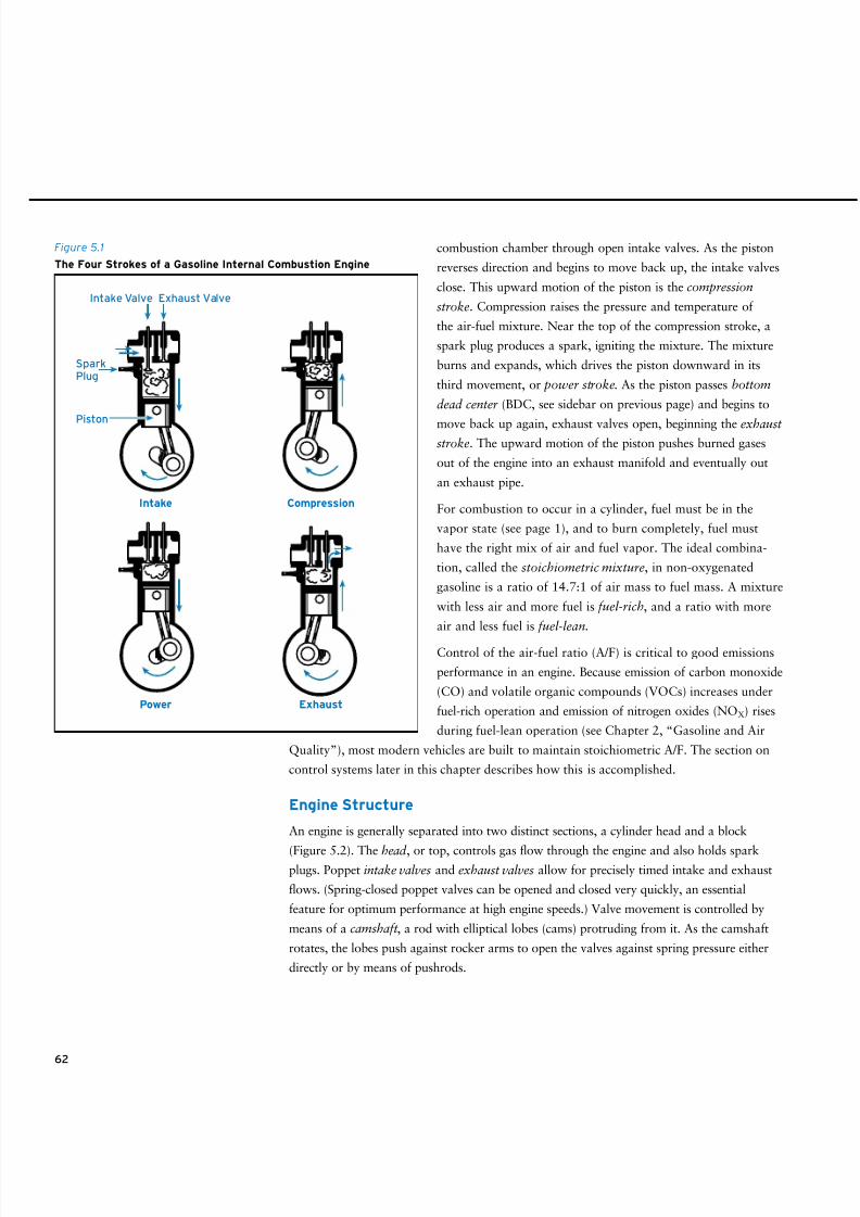
8/9/2019 AAAAAAAA MotorGas Tech Review
http://slidepdf.com/reader/full/aaaaaaaa-motorgas-tech-review 70/124
62
combustion chamber through open intake valves. As the piston
reverses direction and begins to move back up, the intake valves
close. This upward motion of the piston is the compression
stroke. Compression raises the pressure and temperature of
the air-fuel mixture. Near the top of the compression stroke, a
spark plug produces a spark, igniting the mixture. The mixture
burns and expands, which drives the piston downward in its
third movement, or power stroke. As the piston passes bottom
dead center (BDC, see sidebar on previous page) and begins to
move back up again, exhaust valves open, beginning the exhauststroke. The upward motion of the piston pushes burned gases
out of the engine into an exhaust manifold and eventually out
an exhaust pipe.
For combustion to occur in a cylinder, fuel must be in the
vapor state (see page 1), and to burn completely, fuel must
have the right mix of air and fuel vapor. The ideal combina-
tion, called the stoichiometric mixture, in non-oxygenated
gasoline is a ratio of 14.7:1 of air mass to fuel mass. A mixture
with less air and more fuel is fuel-rich, and a ratio with more
air and less fuel is fuel-lean.
Control of the air-fuel ratio (A/F) is critical to good emissions
performance in an engine. Because emission of carbon monoxide
(CO) and volatile organic compounds (VOCs) increases under
fuel-rich operation and emission of nitrogen oxides (NOX) rises
during fuel-lean operation (see Chapter 2, “Gasoline and Air
Quality”), most modern vehicles are built to maintain stoichiometric A/F. The section on
control systems later in this chapter describes how this is accomplished.
Engine Structure
An engine is generally separated into two distinct sections, a cylinder head and a block
(Figure 5.2). The head , or top, controls gas flow through the engine and also holds sparkplugs. Poppet intake valves and exhaust valves allow for precisely timed intake and exhaust
flows. (Spring-closed poppet valves can be opened and closed very quickly, an essential
feature for optimum performance at high engine speeds.) Valve movement is controlled by
means of a camshaft , a rod with elliptical lobes (cams) protruding from it. As the camshaft
rotates, the lobes push against rocker arms to open the valves against spring pressure either
directly or by means of pushrods.
Intake Compression
Power Exhaust
Piston
SparkPlug
Intake Valve Exhaust Valve
Figure 5.1
The Four Strokes of a Gasoline Internal Combustion Engine
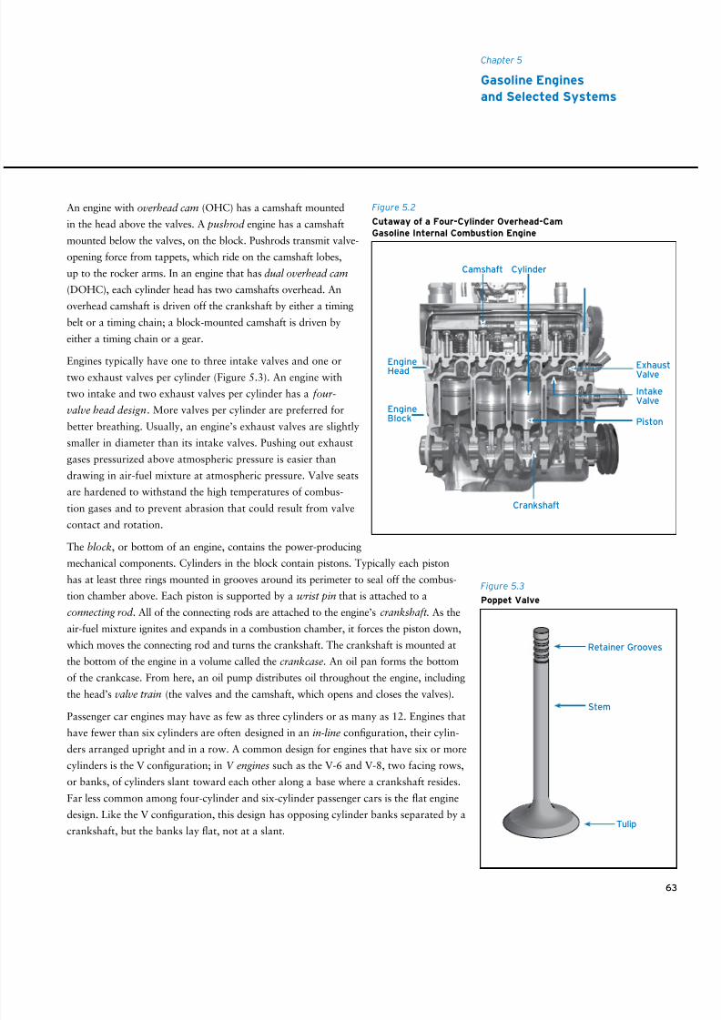
8/9/2019 AAAAAAAA MotorGas Tech Review
http://slidepdf.com/reader/full/aaaaaaaa-motorgas-tech-review 71/124
63
Chapter 5
Gasoline Engines
and Selected Systems
An engine with overhead cam (OHC) has a camshaft mounted
in the head above the valves. A pushrod engine has a camshaft
mounted below the valves, on the block. Pushrods transmit valve-
opening force from tappets, which ride on the camshaft lobes,
up to the rocker arms. In an engine that has dual overhead cam
(DOHC), each cylinder head has two camshafts overhead. An
overhead camshaft is driven off the crankshaft by either a timing
belt or a timing chain; a block-mounted camshaft is driven by
either a timing chain or a gear.
Engines typically have one to three intake valves and one or
two exhaust valves per cylinder (Figure 5.3). An engine with
two intake and two exhaust valves per cylinder has a four-
valve head design. More valves per cylinder are preferred for
better breathing. Usually, an engine’s exhaust valves are slightly
smaller in diameter than its intake valves. Pushing out exhaust
gases pressurized above atmospheric pressure is easier than
drawing in air-fuel mixture at atmospheric pressure. Valve seats
are hardened to withstand the high temperatures of combus-
tion gases and to prevent abrasion that could result from valve
contact and rotation.
The block, or bottom of an engine, contains the power-producing
mechanical components. Cylinders in the block contain pistons. Typically each piston
has at least three rings mounted in grooves around its perimeter to seal off the combus-
tion chamber above. Each piston is supported by a wrist pin that is attached to a
connecting rod . All of the connecting rods are attached to the engine’s crankshaft . As the
air-fuel mixture ignites and expands in a combustion chamber, it forces the piston down,
which moves the connecting rod and turns the crankshaft. The crankshaft is mounted at
the bottom of the engine in a volume called the crankcase. An oil pan forms the bottom
of the crankcase. From here, an oil pump distributes oil throughout the engine, including
the head’s valve train (the valves and the camshaft, which opens and closes the valves).
Passenger car engines may have as few as three cylinders or as many as 12. Engines that
have fewer than six cylinders are often designed in an in-line configuration, their cylin-
ders arranged upright and in a row. A common design for engines that have six or more
cylinders is the V configuration; in V engines such as the V-6 and V-8, two facing rows,
or banks, of cylinders slant toward each other along a base where a crankshaft resides.
Far less common among four-cylinder and six-cylinder passenger cars is the flat engine
design. Like the V configuration, this design has opposing cylinder banks separated by a
crankshaft, but the banks lay flat, not at a slant.
Cylinder
EngineHead
EngineBlock
Crankshaft
Piston
ExhaustValve
IntakeValve
Camshaft
Figure 5.2
Cutaway of a Four-Cylinder Overhead-Cam
Gasoline Internal Combustion Engine
Retainer Grooves
Stem
Tulip
Figure 5.3
Poppet Valve
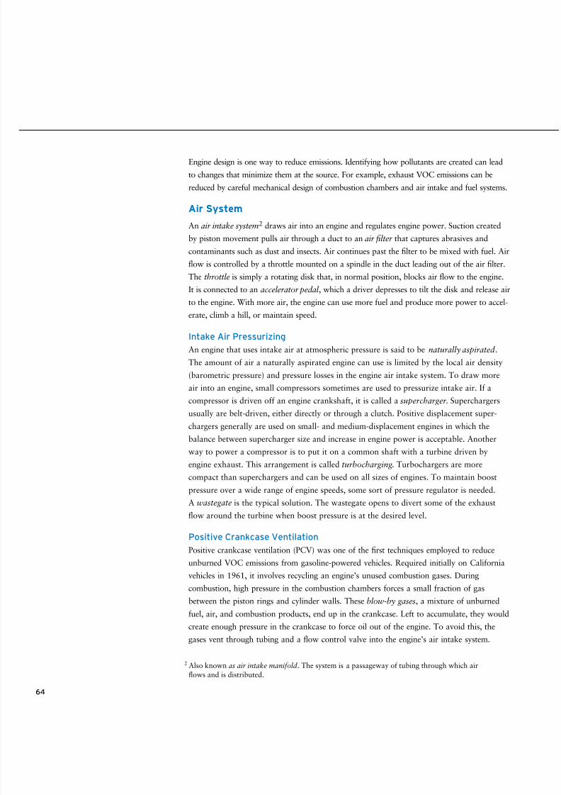
8/9/2019 AAAAAAAA MotorGas Tech Review
http://slidepdf.com/reader/full/aaaaaaaa-motorgas-tech-review 72/124
64
Engine design is one way to reduce emissions. Identifying how pollutants are created can lead
to changes that minimize them at the source. For example, exhaust VOC emissions can be
reduced by careful mechanical design of combustion chambers and air intake and fuel systems.
Air System
An air intake system2 draws air into an engine and regulates engine power. Suction created
by piston movement pulls air through a duct to an air filter that captures abrasives and
contaminants such as dust and insects. Air continues past the filter to be mixed with fuel. Air
flow is controlled by a throttle mounted on a spindle in the duct leading out of the air filter.
The throttle is simply a rotating disk that, in normal position, blocks air flow to the engine.It is connected to an accelerator pedal , which a driver depresses to tilt the disk and release air
to the engine. With more air, the engine can use more fuel and produce more power to accel-
erate, climb a hill, or maintain speed.
Intake Air Pressurizing
An engine that uses intake air at atmospheric pressure is said to be naturally aspirated .
The amount of air a naturally aspirated engine can use is limited by the local air density
(barometric pressure) and pressure losses in the engine air intake system. To draw more
air into an engine, small compressors sometimes are used to pressurize intake air. If a
compressor is driven off an engine crankshaft, it is called a supercharger. Superchargers
usually are belt-driven, either directly or through a clutch. Positive displacement super-chargers generally are used on small- and medium-displacement engines in which the
balance between supercharger size and increase in engine power is acceptable. Another
way to power a compressor is to put it on a common shaft with a turbine driven by
engine exhaust. This arrangement is called turbocharging . Turbochargers are more
compact than superchargers and can be used on all sizes of engines. To maintain boost
pressure over a wide range of engine speeds, some sort of pressure regulator is needed.
A wastegate is the typical solution. The wastegate opens to divert some of the exhaust
flow around the turbine when boost pressure is at the desired level.
Positive Crankcase Ventilation
Positive crankcase ventilation (PCV) was one of the first techniques employed to reduce
unburned VOC emissions from gasoline-powered vehicles. Required initially on California
vehicles in 1961, it involves recycling an engine’s unused combustion gases. During
combustion, high pressure in the combustion chambers forces a small fraction of gas
between the piston rings and cylinder walls. These blow-by gases, a mixture of unburned
fuel, air, and combustion products, end up in the crankcase. Left to accumulate, they would
create enough pressure in the crankcase to force oil out of the engine. To avoid this, the
gases vent through tubing and a flow control valve into the engine’s air intake system.
2 Also known as air intake manifold . The system is a passageway of tubing through which air
flows and is distributed.
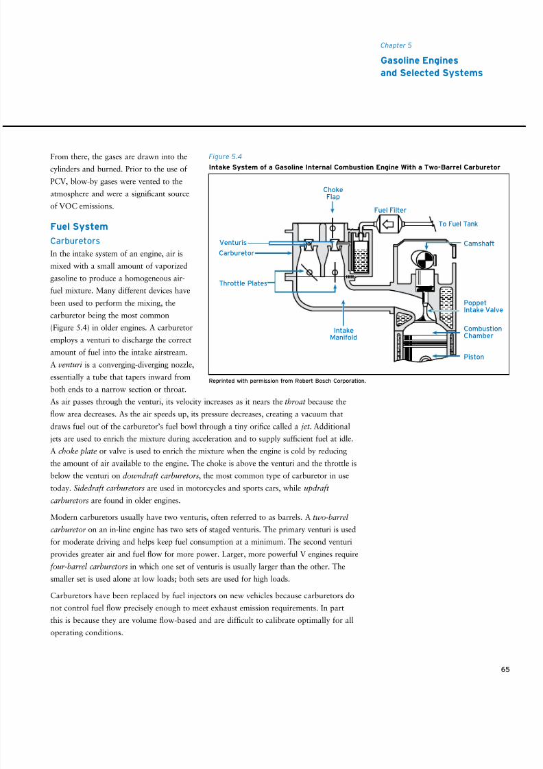
8/9/2019 AAAAAAAA MotorGas Tech Review
http://slidepdf.com/reader/full/aaaaaaaa-motorgas-tech-review 73/124
From there, the gases are drawn into the
cylinders and burned. Prior to the use of
PCV, blow-by gases were vented to the
atmosphere and were a significant source
of VOC emissions.
Fuel System
Carburetors
In the intake system of an engine, air is
mixed with a small amount of vaporizedgasoline to produce a homogeneous air-
fuel mixture. Many different devices have
been used to perform the mixing, the
carburetor being the most common
(Figure 5.4) in older engines. A carburetor
employs a venturi to discharge the correct
amount of fuel into the intake airstream.
A venturi is a converging-diverging nozzle,
essentially a tube that tapers inward from
both ends to a narrow section or throat.
As air passes through the venturi, its velocity increases as it nears the throat because theflow area decreases. As the air speeds up, its pressure decreases, creating a vacuum that
draws fuel out of the carburetor’s fuel bowl through a tiny orifice called a jet . Additional
jets are used to enrich the mixture during acceleration and to supply sufficient fuel at idle.
A choke plate or valve is used to enrich the mixture when the engine is cold by reducing
the amount of air available to the engine. The choke is above the venturi and the throttle is
below the venturi on downdraft carburetors, the most common type of carburetor in use
today. Sidedraft carburetors are used in motorcycles and sports cars, while updraft
carburetors are found in older engines.
Modern carburetors usually have two venturis, often referred to as barrels. A two-barrel
carburetor on an in-line engine has two sets of staged venturis. The primary venturi is used
for moderate driving and helps keep fuel consumption at a minimum. The second venturi
provides greater air and fuel flow for more power. Larger, more powerful V engines require
four-barrel carburetors in which one set of venturis is usually larger than the other. The
smaller set is used alone at low loads; both sets are used for high loads.
Carburetors have been replaced by fuel injectors on new vehicles because carburetors do
not control fuel flow precisely enough to meet exhaust emission requirements. In part
this is because they are volume flow-based and are difficult to calibrate optimally for all
operating conditions.
65
Chapter 5
Gasoline Engines
and Selected Systems
Fuel Filter
Camshaft
To Fuel Tank
IntakeManifold
Venturis
Carburetor
Throttle Plates
CombustionChamber
PoppetIntake Valve
Piston
ChokeFlap
Reprinted with permission from Robert Bosch Corporation.
Figure 5.4
Intake System of a Gasoline Internal Combustion Engine With a Two-Barrel Carburetor
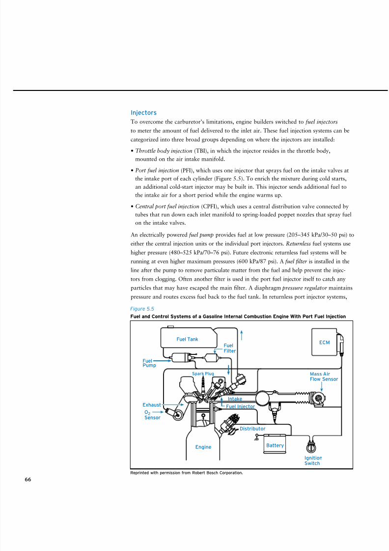
8/9/2019 AAAAAAAA MotorGas Tech Review
http://slidepdf.com/reader/full/aaaaaaaa-motorgas-tech-review 74/124
Injectors
To overcome the carburetor’s limitations, engine builders switched to fuel injectors
to meter the amount of fuel delivered to the inlet air. These fuel injection systems can be
categorized into three broad groups depending on where the injectors are installed:
• Throttle body injection (TBI), in which the injector resides in the throttle body,
mounted on the air intake manifold.
• Port fuel injection (PFI), which uses one injector that sprays fuel on the intake valves at
the intake port of each cylinder (Figure 5.5). To enrich the mixture during cold starts,
an additional cold-start injector may be built in. This injector sends additional fuel to
the intake air for a short period while the engine warms up.
• Central port fuel injection (CPFI), which uses a central distribution valve connected by
tubes that run down each inlet manifold to spring-loaded poppet nozzles that spray fuel
on the intake valves.
An electrically powered fuel pump provides fuel at low pressure (205–345 kPa/30–50 psi) to
either the central injection units or the individual port injectors. Returnless fuel systems use
higher pressure (480–525 kPa/70–76 psi). Future electronic returnless fuel systems will be
running at even higher maximum pressures (600 kPa/87 psi). A fuel filter is installed in the
line after the pump to remove particulate matter from the fuel and help prevent the injec-
tors from clogging. Often another filter is used in the port fuel injector itself to catch any
particles that may have escaped the main filter. A diaphragm pressure regulator maintainspressure and routes excess fuel back to the fuel tank. In returnless port injector systems,
66
ECM
Battery
Fuel Tank
FuelPump
Exhaust
O2Sensor
Engine
Distributor
Fuel Injector
Intake
Spark Plug
FuelFilter
Mass AirFlow Sensor
IgnitionSwitch
Figure 5.5
Fuel and Control Systems of a Gasoline Internal Combustion Engine With Port Fuel Injection
Reprinted with permission from Robert Bosch Corporation.
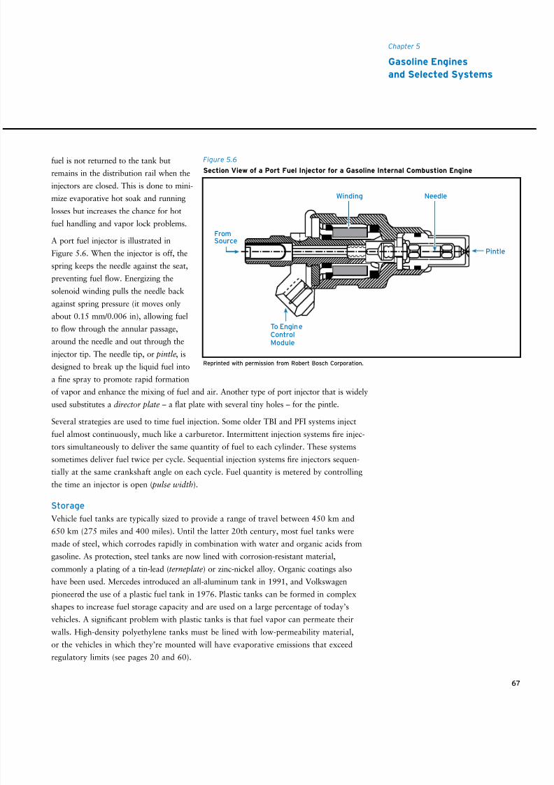
8/9/2019 AAAAAAAA MotorGas Tech Review
http://slidepdf.com/reader/full/aaaaaaaa-motorgas-tech-review 75/124
8/9/2019 AAAAAAAA MotorGas Tech Review
http://slidepdf.com/reader/full/aaaaaaaa-motorgas-tech-review 76/124
68
Evaporative emissions control systems have been employed on all gasoline passenger cars
sold in California since 1970 and throughout the United States since 1971. These systems
collect vapor resulting from the evaporation of gasoline in the fuel tank and introduce it
into the engine later. The heart of the system is a canister containing activated carbon. It is
positioned in the line through which the tank breathes, drawing in air from the atmosphere
as gasoline is consumed or when the tank temperature drops and emitting air when the
tank temperature rises. The activated carbon absorbs gasoline vapor in the emitted air like a
sponge absorbs water, preventing the vapor from reaching the atmosphere. The canister also
is connected to the engine’s air intake system by the purge control valve, which is opened at
certain times to allow the accumulated vapors to be purged from the canister and burned inthe engine. For the system to work, the canister must be the tank’s only vent to the atmo-
sphere. The filler tube must be sealed by a functional, properly tightened gas cap.
Other sources of fuel-related emissions, such as those resulting from fuel leaks, seepage,
or permeation through hoses and tanks, can be controlled through design, raw material
choices, and prompt repair.
Exhaust System
Combustion gases are routed out of the engine by the exhaust system, which has four parts:
exhaust manifold, exhaust pipe, catalytic converter, and muffler. The exhaust manifold
collects exhaust gases from several cylinders and combines them into one flow stream. The
exhaust pipe runs from the exhaust manifold underneath the vehicle to the rear. The catalytic
converter and the muffler, which reduces engine noise, are mounted in the exhaust pipe.
Catalytic Converter
A catalytic converter may be the most important emission control device on a vehicle.
Simply a canister positioned between the engine and exhaust pipe, it holds catalysts that
convert pollutants into nonpolluting compounds as they pass through the exhaust system
to the atmosphere. The catalysts contain precious metals such as platinum, palladium, and
rhodium. Close-coupled catalytic converters are positioned near the engine. Underfloor
catalytic converters sit under the floor of a vehicle next to or as part of its muffler.
The first catalysts were oxidation catalysts. As the name indicates, they were used to oxidize
CO and VOCs into carbon dioxide and water. To work properly, the catalyst required excess
oxygen in the exhaust, made available either by operating the engine with a fuel-lean mixture
or by injecting air directly into the exhaust stream between the engine and the catalyst.
Converters have been installed on gasoline-powered vehicles since 1975 in the U.S, and
three-way catalytic converters, introduced around 1980, are now used almost exclusively.
Catalytic Converters and
Unleaded Gasoline
Unleaded gasoline is critical to the func-
tion of catalytic converters. In vehicles
equipped with catalytic converters,
leaded gasoline will quickly terminate
catalytic activity altogether. Metals in the
catalyst adsorb lead from engine exhaust,
which creates a barrier that inhibits the
catalyst from treating emissions.
8/9/2019 AAAAAAAA MotorGas Tech Review
http://slidepdf.com/reader/full/aaaaaaaa-motorgas-tech-review 77/124
69
Chapter 5
Gasoline Engines
and Selected Systems
They perform the oxidation function just described and also reduce NOX into nitrogen
and oxygen. Excess oxygen interferes with the NOX reduction reaction, so the three-way
catalytic converter performs best when A/F is very near stoichiometric value. Thus, careful
control of A/F is doubly important on modern cars: first, to minimize the formation of CO and
VOCs in the engine, and second, to maximize efficiency of the three-way catalytic converter.
To meet ever more stringent exhaust emission requirements, an engine may be designed
with additional converters mounted at the exit of the exhaust manifold before the under-
floor converter. Other designs involve a single converter placed closer to the exhaust mani-
fold. Such designs allow converters to light off (that is, reach the heat necessary to begin
functioning) more quickly and thereby reduce emissions sooner after ignition. Some systems
also use insulated exhaust pipes to assure faster warm-up of the converters.
Most converters today consist of a monolithic (honeycomb-style) substrate that has parallel
channels coated with catalytically active material. Brick-like in form, the substrate may
have a cell density at or below 400 cells (or channels) per square inch. To meet stricter
emission limits in the future, cell densities are likely to reach as high as 1,200 cells per
square inch. With slimmer, more numerous channels, the substrate will have more active
surface area to treat exhaust but will also be more prone to plugging by exhaust particles.
Exhaust Gas Recirculation
Exhaust gas recirculation (EGR) is a strategy employed in many modern gasoline engines
to reduce NOX emissions. The principle is relatively simple: Exhaust gas is essentially
inert since it has already been burned. If some of this exhaust gas is introduced into the
intake manifold (recirculated) along with air and fuel, it won’t participate in the combus-
tion reactions. However, the exhaust gas can absorb some of the heat produced, thereby
lowering cylinder temperature. Because higher temperatures strongly influence NOX
production, EGR reduces NOX emissions substantially. The mechanics of EGR involve
appropriate piping between engine exhaust and inlet systems and a control valve to regulate
the amount of exhaust that is recirculated. When implemented properly, EGR can increase
fuel economy under cruise conditions.
Control Systems
Fuel Control
To meet the conflicting goals of high power, good fuel economy, and low emissions, engine
designers have had to develop high-speed, computerized engine control systems. Sensors
monitor various conditions and generate information that an electronic control module
(ECM) collects and uses to respond to driver input. Table 5.1 lists the conditions under
which an ECM may monitor newer vehicles and the functions it may help control.
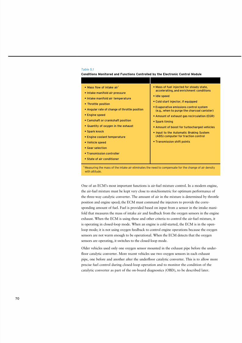
8/9/2019 AAAAAAAA MotorGas Tech Review
http://slidepdf.com/reader/full/aaaaaaaa-motorgas-tech-review 78/124
One of an ECM’s most important functions is air-fuel mixture control. In a modern engine,
the air-fuel mixture must be kept very close to stoichiometric for optimum performance of
the three-way catalytic converter. The amount of air in the mixture is determined by throttle
position and engine speed; the ECM must command the injectors to provide the corre-
sponding amount of fuel. Fuel is provided based on input from a sensor in the intake mani-
fold that measures the mass of intake air and feedback from the oxygen sensors in the engine
exhaust. When the ECM is using these and other criteria to control the air-fuel mixture, it
is operating in closed-loop mode. When an engine is cold-started, the ECM is in the open-
loop mode; it is not using oxygen feedback to control engine operations because the oxygen
sensors are not warm enough to be operational. When the ECM detects that the oxygen
sensors are operating, it switches to the closed-loop mode.
Older vehicles used only one oxygen sensor mounted in the exhaust pipe before the under-
floor catalytic converter. More recent vehicles use two oxygen sensors in each exhaust
pipe, one before and another after the underfloor catalytic converter. This is to allow more
precise fuel control during closed-loop operation and to monitor the condition of the
catalytic converter as part of the on-board diagnostics (OBD), to be described later.
70
• Mass flow of intake air1
• Intake manifold air pressure
• Intake manifold air temperature
• Throttle position
• Angular rate of change of throttle position
• Engine speed
• Camshaft or crankshaft position
• Quantity of oxygen in the exhaust
• Spark knock
• Engine coolant temperature
• Vehicle speed
• Gear selection
• Transmission controller
• State of air conditioner
Table 5.1
Conditions Monitored and Functions Controlled by the Electronic Control Module
1 Measuring the mass of the intake air eliminates the need to compensate for the change of air density
with altitude.
• Mass of fuel injected for steady state,accelerating, and enrichment conditions
• Idle speed
• Cold start injector, if equipped
• Evaporative emissions control system(e.g., when to purge the charcoal canister)
• Amount of exhaust gas recirculation (EGR)
• Spark timing
• Amount of boost for turbocharged vehicles
• Input to the Automatic Braking System(ABS) computer for traction control
• Transmission shift points
Conditions That May Be Monitored Functions That May Be Controlled
8/9/2019 AAAAAAAA MotorGas Tech Review
http://slidepdf.com/reader/full/aaaaaaaa-motorgas-tech-review 79/124
71
Chapter 5
Gasoline Engines
and Selected Systems
Under steady-state conditions, closed-loop control based on direct oxygen sensor input
works well, but it breaks down under transient conditions. When a driver suddenly opens
the throttle to accelerate, the new situation is not immediately reflected in the feedback from
the oxygen sensor. Time is needed for the engine to burn the fuel mixture, for the oxygen
sensor to measure the oxygen content of the exhaust, and for the ECM to command the
injectors to inject more fuel. Before the release of additional fuel is triggered, the air-fuel
mixture is fuel-lean, which could cause driveability and emissions problems. To compensate,
under transient conditions “the ECM uses an anticipatory control strategy that uses engine
load and rpm to determine the approximate fuel requirement.”3 The ECM consults a data
table (map) in its memory to determine the amount of fuel to inject for the transient combi-nation of engine load and rpm. The map is developed by the engine manufacturer through
system modeling and engine testing.
With structural variations among engines, changes that result from wear and aging, and
variations in fuel characteristics, the factory-installed map can’t represent the best answer.
For this reason, the ECM is equipped with an adaptive learning feature that enables it to
use oxygen sensor input to generate a second engine load/rpm map for current conditions.
This second map is continually updated. The next time the engine reaches the same load/
rpm operating point, the anticipatory control value will be closer to the correct value for
the specific engine and fuel.
Several special situations require different fuel control strategies. An engine needs extra fuel,a mixture enrichment , for starting, for hard acceleration, and at wide-open throttle (WOT)
operation. When an engine is cold, fuel vaporizes more slowly, so extra fuel is needed to
ensure that combustion will occur (A/F = 13:1 for optimum startability). Some injector
systems use an additional cold-start injector to provide extra fuel. The cold-start injector
typically operates for only a few seconds until a stable idle is achieved. Other designs simply
program the port fuel injectors to inject more fuel.
Another form of mixture enrichment, called commanded enrichment , is used under hard
acceleration and at WOT to keep the gas temperatures in the combustion chambers from
becoming too hot. This helps reduce the potential for knocking and avoids overheating the
catalytic converter.
Idling is a common operating condition, especially in city driving. Idle speed refers to
power needed to run a vehicle’s engine while the vehicle is not moving. To minimize
fuel consumption, idle speed should be set as low as possible. It is usually controlled by
adjusting the flow of air-fuel mixture, although it also can be controlled by adjusting
ignition timing.
3 Jurgen, Ronald K. (ed.), Automotive Electronics Handbook, McGraw-Hill, New York, 1995.
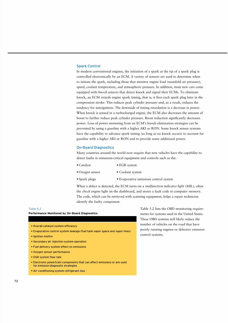
8/9/2019 AAAAAAAA MotorGas Tech Review
http://slidepdf.com/reader/full/aaaaaaaa-motorgas-tech-review 80/124
72
Spark Control
In modern conventional engines, the initiation of a spark at the tip of a spark plug is
controlled electronically by an ECM. A variety of sensors are used to determine when
to initiate the spark, including those that monitor engine load (manifold air pressure),
speed, coolant temperature, and atmospheric pressure. In addition, most new cars come
equipped with knock sensors that detect knock and signal their ECMs. To eliminate
knock, an ECM retards engine spark timing, that is, it fires each spark plug later in the
compression stroke. This reduces peak cylinder pressure and, as a result, reduces the
tendency for autoignition. The downside of timing retardation is a decrease in power.
When knock is sensed in a turbocharged engine, the ECM also decreases the amount ofboost to further reduce peak cylinder pressure. Boost reduction significantly decreases
power. Loss of power stemming from an ECM’s knock-elimination strategies can be
prevented by using a gasoline with a higher AKI or RON. Some knock sensor systems
have the capability to advance spark timing (as long as no knock occurs) to account for
gasoline with a higher AKI or RON and to provide some additional power.
On-Board Diagnostics
Many countries around the world now require that new vehicles have the capability to
detect faults in emissions-critical equipment and controls such as the:
• Catalyst • EGR system
• Oxygen sensor • Coolant system
• Spark plugs • Evaporative emissions control system
When a defect is detected, the ECM turns on a malfunction indicator light (MIL), often
the check engine light on the dashboard, and stores a fault code in computer memory.
The code, which can be retrieved with scanning equipment, helps a repair technician
identify the faulty component.
Table 5.2 lists the OBD monitoring require-
ments for systems used in the United States.
These OBD systems will likely reduce the
number of vehicles on the road that have
poorly running engines or defective emission
control systems.
• Overall catalyst system efficiency
• Evaporative control system leakage (fuel tank vapor space and vapor lines)
• Ignition misfire
• Secondary air injection system operation
• Fuel delivery system effect on emissions
• Oxygen sensor performance
• EGR system flow rate
• Electronic powertrain components that can affect emissions or are usedfor emission diagnostic strategies
• Air conditioning system refrigerant loss
Table 5.2
Performance Monitored by On-Board Diagnostics
Performance Area
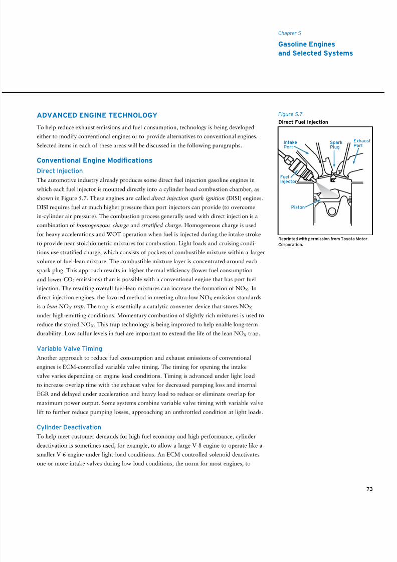
8/9/2019 AAAAAAAA MotorGas Tech Review
http://slidepdf.com/reader/full/aaaaaaaa-motorgas-tech-review 81/124
ADVANCED ENGINE TECHNOLOGY
To help reduce exhaust emissions and fuel consumption, technology is being developed
either to modify conventional engines or to provide alternatives to conventional engines.
Selected items in each of these areas will be discussed in the following paragraphs.
Conventional Engine Modications
Direct Injection
The automotive industry already produces some direct fuel injection gasoline engines in
which each fuel injector is mounted directly into a cylinder head combustion chamber, as
shown in Figure 5.7. These engines are called direct injection spark ignition (DISI) engines.
DISI requires fuel at much higher pressure than port injectors can provide (to overcome
in-cylinder air pressure). The combustion process generally used with direct injection is a
combination of homogeneous charge and stratified charge. Homogeneous charge is used
for heavy accelerations and WOT operation when fuel is injected during the intake stroke
to provide near stoichiometric mixtures for combustion. Light loads and cruising condi-
tions use stratified charge, which consists of pockets of combustible mixture within a larger
volume of fuel-lean mixture. The combustible mixture layer is concentrated around each
spark plug. This approach results in higher thermal efficiency (lower fuel consumption
and lower CO2 emissions) than is possible with a conventional engine that has port fuel
injection. The resulting overall fuel-lean mixtures can increase the formation of NOX. In
direct injection engines, the favored method in meeting ultra-low NOX emission standards
is a lean NOX trap. The trap is essentially a catalytic converter device that stores NOX
under high-emitting conditions. Momentary combustion of slightly rich mixtures is used to
reduce the stored NOX. This trap technology is being improved to help enable long-term
durability. Low sulfur levels in fuel are important to extend the life of the lean NOX trap.
Variable Valve Timing
Another approach to reduce fuel consumption and exhaust emissions of conventional
engines is ECM-controlled variable valve timing. The timing for opening the intake
valve varies depending on engine load conditions. Timing is advanced under light load
to increase overlap time with the exhaust valve for decreased pumping loss and internal
EGR and delayed under acceleration and heavy load to reduce or eliminate overlap formaximum power output. Some systems combine variable valve timing with variable valve
lift to further reduce pumping losses, approaching an unthrottled condition at light loads.
Cylinder Deactivation
To help meet customer demands for high fuel economy and high performance, cylinder
deactivation is sometimes used, for example, to allow a large V-8 engine to operate like a
smaller V-6 engine under light-load conditions. An ECM-controlled solenoid deactivates
one or more intake valves during low-load conditions, the norm for most engines, to
73
Chapter 5
Gasoline Engines
and Selected Systems
Figure 5.7
Direct Fuel Injection
FuelInjector
IntakePort
ExhaustPort
SparkPlug
Piston
Reprinted with permission from Toyota Motor
Corporation.
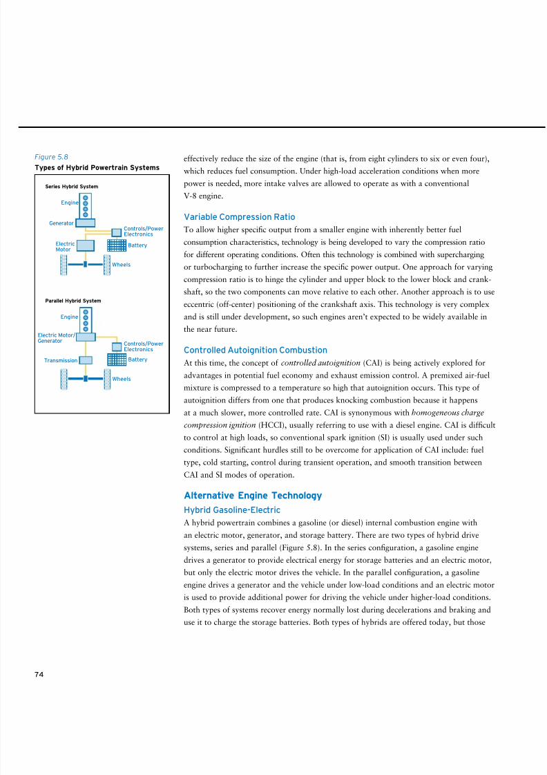
8/9/2019 AAAAAAAA MotorGas Tech Review
http://slidepdf.com/reader/full/aaaaaaaa-motorgas-tech-review 82/124
74
Figure 5.8
Types of Hybrid Powertrain Systems
Battery
Wheels
Controls/PowerElectronics
Controls/PowerElectronics
Engine
Series Hybrid System
Parallel Hybrid System
Transmission
Generator
ElectricMotor
Battery
Wheels
Engine
Electric Motor/Generator
effectively reduce the size of the engine (that is, from eight cylinders to six or even four),
which reduces fuel consumption. Under high-load acceleration conditions when more
power is needed, more intake valves are allowed to operate as with a conventional
V-8 engine.
Variable Compression Ratio
To allow higher specific output from a smaller engine with inherently better fuel
consumption characteristics, technology is being developed to vary the compression ratio
for different operating conditions. Often this technology is combined with supercharging
or turbocharging to further increase the specific power output. One approach for varyingcompression ratio is to hinge the cylinder and upper block to the lower block and crank-
shaft, so the two components can move relative to each other. Another approach is to use
eccentric (off-center) positioning of the crankshaft axis. This technology is very complex
and is still under development, so such engines aren’t expected to be widely available in
the near future.
Controlled Autoignition Combustion
At this time, the concept of controlled autoignition (CAI) is being actively explored for
advantages in potential fuel economy and exhaust emission control. A premixed air-fuel
mixture is compressed to a temperature so high that autoignition occurs. This type of
autoignition differs from one that produces knocking combustion because it happens
at a much slower, more controlled rate. CAI is synonymous with homogeneous charge
compression ignition (HCCI), usually referring to use with a diesel engine. CAI is difficult
to control at high loads, so conventional spark ignition (SI) is usually used under such
conditions. Significant hurdles still to be overcome for application of CAI include: fuel
type, cold starting, control during transient operation, and smooth transition between
CAI and SI modes of operation.
Alternative Engine Technology
Hybrid Gasoline-Electric
A hybrid powertrain combines a gasoline (or diesel) internal combustion engine with
an electric motor, generator, and storage battery. There are two types of hybrid drive
systems, series and parallel (Figure 5.8). In the series configuration, a gasoline engine
drives a generator to provide electrical energy for storage batteries and an electric motor,
but only the electric motor drives the vehicle. In the parallel configuration, a gasoline
engine drives a generator and the vehicle under low-load conditions and an electric motor
is used to provide additional power for driving the vehicle under higher-load conditions.
Both types of systems recover energy normally lost during decelerations and braking and
use it to charge the storage batteries. Both types of hybrids are offered today, but those
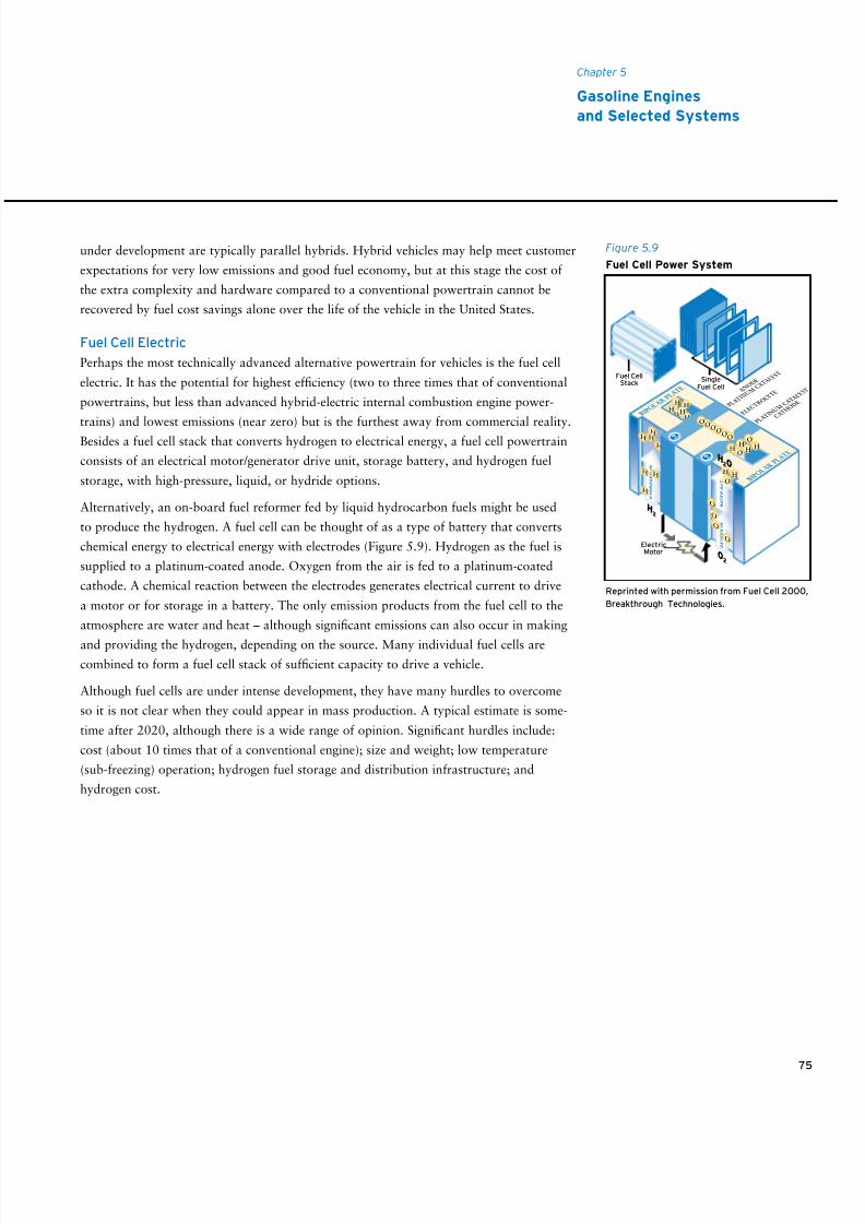
8/9/2019 AAAAAAAA MotorGas Tech Review
http://slidepdf.com/reader/full/aaaaaaaa-motorgas-tech-review 83/124
75
Chapter 5
Gasoline Engines
and Selected Systems
Figure 5.9
Fuel Cell Power System
Fuel CellStack
SingleFuel Cell A N
O D E
P L A T I N U M
C A T
A L Y S T
P L A T I N U M
C A T
A L Y S T
C A T H
O D E
HHH
E L E C
T R O L Y T
E
ElectricMotor
H B I P O
L A R P L
A T E
B I P O
L A R
P L A
T E
O X Y G E N I N
H Y D R O G E N I N
W A T E R O U T
OO
OOOO
O
O
O
O
O
H
H
H
H
HHH
HH
H
H
H2O
O2
H2
H
OH H
O
H H
Reprinted with permission from Fuel Cell 2000,
Breakthrough Technologies.
under development are typically parallel hybrids. Hybrid vehicles may help meet customer
expectations for very low emissions and good fuel economy, but at this stage the cost of
the extra complexity and hardware compared to a conventional powertrain cannot be
recovered by fuel cost savings alone over the life of the vehicle in the United States.
Fuel Cell Electric
Perhaps the most technically advanced alternative powertrain for vehicles is the fuel cell
electric. It has the potential for highest efficiency (two to three times that of conventional
powertrains, but less than advanced hybrid-electric internal combustion engine power-
trains) and lowest emissions (near zero) but is the furthest away from commercial reality.Besides a fuel cell stack that converts hydrogen to electrical energy, a fuel cell powertrain
consists of an electrical motor/generator drive unit, storage battery, and hydrogen fuel
storage, with high-pressure, liquid, or hydride options.
Alternatively, an on-board fuel reformer fed by liquid hydrocarbon fuels might be used
to produce the hydrogen. A fuel cell can be thought of as a type of battery that converts
chemical energy to electrical energy with electrodes (Figure 5.9). Hydrogen as the fuel is
supplied to a platinum-coated anode. Oxygen from the air is fed to a platinum-coated
cathode. A chemical reaction between the electrodes generates electrical current to drive
a motor or for storage in a battery. The only emission products from the fuel cell to the
atmosphere are water and heat – although significant emissions can also occur in making
and providing the hydrogen, depending on the source. Many individual fuel cells are
combined to form a fuel cell stack of sufficient capacity to drive a vehicle.
Although fuel cells are under intense development, they have many hurdles to overcome
so it is not clear when they could appear in mass production. A typical estimate is some-
time after 2020, although there is a wide range of opinion. Significant hurdles include:
cost (about 10 times that of a conventional engine); size and weight; low temperature
(sub-freezing) operation; hydrogen fuel storage and distribution infrastructure; and
hydrogen cost.

8/9/2019 AAAAAAAA MotorGas Tech Review
http://slidepdf.com/reader/full/aaaaaaaa-motorgas-tech-review 84/124
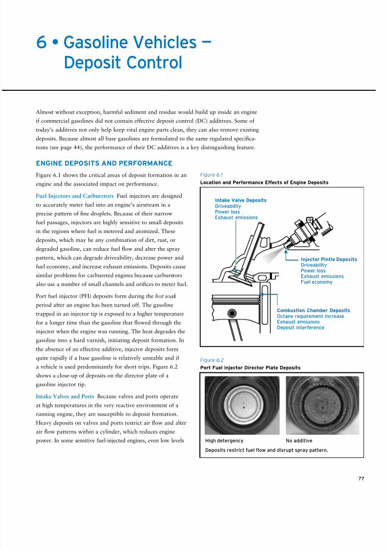
8/9/2019 AAAAAAAA MotorGas Tech Review
http://slidepdf.com/reader/full/aaaaaaaa-motorgas-tech-review 85/124
77
6 • Gasoline Vehicles —Deposit Control
Almost without exception, harmful sediment and residue would build up inside an engine
if commercial gasolines did not contain effective deposit control (DC) additives. Some of
today’s additives not only help keep vital engine parts clean, they can also remove existing
deposits. Because almost all base gasolines are formulated to the same regulated specifica-
tions (see page 44), the performance of their DC additives is a key distinguishing feature.
ENGINE DEPOSITS AND PERFORMANCE
Figure 6.1 shows the critical areas of deposit formation in an
engine and the associated impact on performance.
Fuel Injectors and Carburetors Fuel injectors are designed
to accurately meter fuel into an engine’s airstream in a
precise pattern of fine droplets. Because of their narrow
fuel passages, injectors are highly sensitive to small deposits
in the regions where fuel is metered and atomized. These
deposits, which may be any combination of dirt, rust, or
degraded gasoline, can reduce fuel flow and alter the spray
pattern, which can degrade driveability, decrease power and
fuel economy, and increase exhaust emissions. Deposits cause
similar problems for carbureted engines because carburetors
also use a number of small channels and orifices to meter fuel.
Port fuel injector (PFI) deposits form during the hot soak
period after an engine has been turned off. The gasoline
trapped in an injector tip is exposed to a higher temperature
for a longer time than the gasoline that flowed through the
injector when the engine was running. The heat degrades the
gasoline into a hard varnish, initiating deposit formation. In
the absence of an effective additive, injector deposits form
quite rapidly if a base gasoline is relatively unstable and if
a vehicle is used predominantly for short trips. Figure 6.2
shows a close-up of deposits on the director plate of a
gasoline injector tip.
Intake Valves and Ports Because valves and ports operate
at high temperatures in the very reactive environment of a
running engine, they are susceptible to deposit formation.
Heavy deposits on valves and ports restrict air flow and alter
air flow patterns within a cylinder, which reduces engine
power. In some sensitive fuel-injected engines, even low levels
Intake Valve Deposits
DriveabilityPower lossExhaust emissions
Injector Pintle DepositsDriveabilityPower lossExhaust emissionsFuel economy
Combustion Chamber DepositsOctane requirement increaseExhaust emissionsDeposit interference
Figure 6.1
Location and Performance Effects of Engine Deposits
Figure 6.2
Port Fuel Injector Director Plate Deposits
High detergency No additive
Deposits restrict fuel flow and disrupt spray pattern.
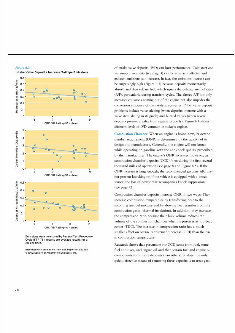
8/9/2019 AAAAAAAA MotorGas Tech Review
http://slidepdf.com/reader/full/aaaaaaaa-motorgas-tech-review 86/124
78
of intake valve deposits (IVD) can hurt performance. Cold-start and
warm-up driveability (see page 3) can be adversely affected and
exhaust emissions can increase. In fact, the emissions increase can
be surprisingly high (Figure 6.3) because deposits momentarily
absorb and then release fuel, which upsets the delicate air-fuel ratio
(A/F), particularly during transient cycles. The altered A/F not only
increases emissions coming out of the engine but also impedes the
conversion efficiency of the catalytic converter. Other valve deposit
problems include valve sticking (when deposits interfere with a
valve stem sliding in its guide) and burned valves (when severedeposits prevent a valve from seating properly). Figure 6.4 shows
different levels of IVD common in today’s engines.
Combustion Chamber When an engine is brand-new, its octane
number requirement (ONR) is determined by the quality of its
design and manufacture. Generally, the engine will not knock
while operating on gasoline with the antiknock quality prescribed
by the manufacturer. The engine’s ONR increases, however, as
combustion chamber deposits (CCD) form during the first several
thousand miles of operation (see page 8 and Figure 6.5). If the
ONR increase is large enough, the recommended gasoline AKI may
not prevent knocking or, if the vehicle is equipped with a knock
sensor, the loss of power that accompanies knock suppression
(see page 72).
Combustion chamber deposits increase ONR in two ways: They
increase combustion temperature by transferring heat to the
incoming air-fuel mixture and by slowing heat transfer from the
combustion gases (thermal insulation). In addition, they increase
the compression ratio because their bulk volume reduces the
volume of the combustion chamber when its piston is at top dead
center (TDC). The increase in compression ratio has a much
smaller effect on octane requirement increase (ORI) than the risein combustion temperature.
Research shows that precursors for CCD come from fuel, some
fuel additives, and engine oil and that certain fuel and engine oil
components form more deposits than others. To date, the only
quick, effective means of removing these deposits is to treat gaso-
6 7 8 9
6 7 8 9
6 7 8 9
CRC IVD Rating (10 = clean)
H y d r o c a r b o n s ( H C ) , g / m i l e
0
0.1
0.2
0.3
0.4
0.5
0.6
0
0.1
0.2
0.3
0.4
0.5
CRC IVD Rating (10 = clean)
C a r b o n M o n o x i d e ( C O ) , g / m i l e
0
1
2
3
4
5
CRC IVD Rating (10 = clean)
O x i d e s o f N i t r o g e n ( N O x ) , g / m i l e
Emissions were measured by Federal Test ProcedureCycle (FTP 75); results are average results for a20-car eet.
Reprinted with permission from SAE Paper No. 922259
© 1992 Society of Automotive Engineers, Inc.
Figure 6.3
Intake Valve Deposits Increase Tailpipe Emissions
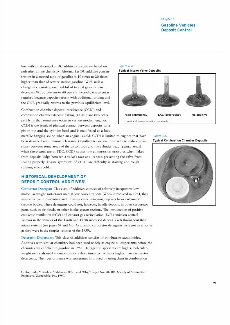
8/9/2019 AAAAAAAA MotorGas Tech Review
http://slidepdf.com/reader/full/aaaaaaaa-motorgas-tech-review 87/124
79
Chapter 6
Gasoline Vehicles –Deposit Control
line with an aftermarket DC additive concentrate based on
polyether amine chemistry. Aftermarket DC additive concen-
tration in a treated tank of gasoline is 10 times to 20 times
higher than that of service station gasoline. With such a
change in chemistry, one tankful of treated gasoline can
decrease ORI 30 percent to 40 percent. Periodic treatment is
required because deposits reform with additional driving and
the ONR gradually returns to the previous equilibrium level.
Combustion chamber deposit interference (CCDI) and
combustion chamber deposit flaking (CCDF) are two other
problems that sometimes occur in certain modern engines.
CCDI is the result of physical contact between deposits on a
piston top and the cylinder head and is manifested as a loud,
metallic banging sound when an engine is cold. CCDI is limited to engines that have
been designed with minimal clearance (1 millimeter or less, primarily to reduce emis-
sions) between some areas of the piston tops and the cylinder head ( squish areas)
when the pistons are at TDC. CCDF causes low compression pressures when flakes
from deposits lodge between a valve’s face and its seat, preventing the valve from
sealing properly. Engine symptoms of CCDF are difficulty in starting and rough
running when cold.
HISTORICAL DEVELOPMENT OF
DEPOSIT CONTROL ADDITIVES1
Carburetor Detergent This class of additives consists of relatively inexpensive low-
molecular-weight surfactants used at low concentrations. When introduced in 1954, they
were effective in preventing and, in many cases, removing deposits from carburetor
throttle bodies. These detergents could not, however, handle deposits in other carburetor
parts, such as air bleeds, or other intake system sections. The introduction of positive
crankcase ventilation (PCV) and exhaust gas recirculation (EGR) emission control
systems in the vehicles of the 1960s and 1970s increased deposit levels throughout their
intake systems (see pages 64 and 69). As a result, carburetor detergents were not as effective
as they were in the simpler vehicles of the 1950s.
Detergent-Dispersants This class of additives consists of polybutene succinimides.
Additives with similar chemistry had been used widely as engine oil dispersants before the
chemistry was applied to gasoline in 1968. Detergent-dispersants are higher-molecular-
weight materials used at concentrations three times to five times higher than carburetor
detergents. Their performance was sometimes improved by using them in combination
1 Gibbs, L.M., “Gasoline Additives – When and Why,” Paper No. 902104, Society of Automotive
Engineers, Warrendale, Pa., 1990.
Figure 6.4
Typical Intake Valve Deposits
High detergency LAC1 detergency No additive
Figure 6.5
Typical Combustion Chamber Deposits
1 Lowest additive concentration; see page 81.
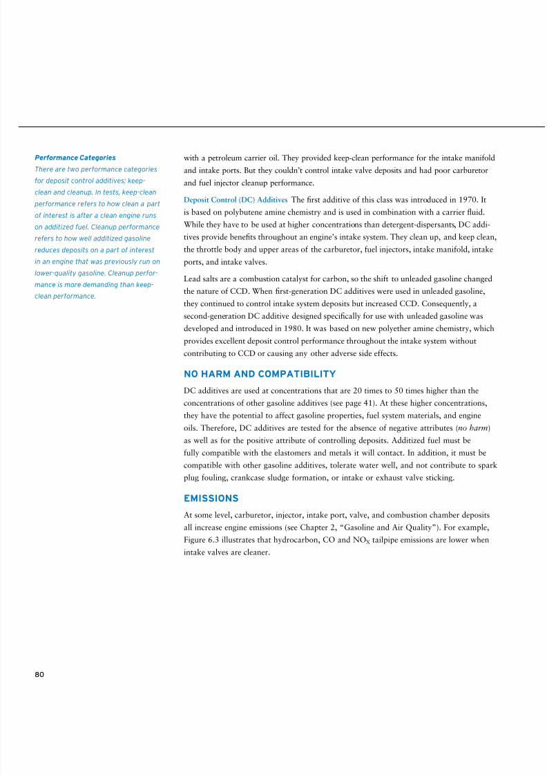
8/9/2019 AAAAAAAA MotorGas Tech Review
http://slidepdf.com/reader/full/aaaaaaaa-motorgas-tech-review 88/124
80
with a petroleum carrier oil. They provided keep-clean performance for the intake manifold
and intake ports. But they couldn’t control intake valve deposits and had poor carburetor
and fuel injector cleanup performance.
Deposit Control (DC) Additives The first additive of this class was introduced in 1970. It
is based on polybutene amine chemistry and is used in combination with a carrier fluid.
While they have to be used at higher concentrations than detergent-dispersants, DC addi-
tives provide benefits throughout an engine’s intake system. They clean up, and keep clean,
the throttle body and upper areas of the carburetor, fuel injectors, intake manifold, intake
ports, and intake valves.
Lead salts are a combustion catalyst for carbon, so the shift to unleaded gasoline changed
the nature of CCD. When first-generation DC additives were used in unleaded gasoline,
they continued to control intake system deposits but increased CCD. Consequently, a
second-generation DC additive designed specifically for use with unleaded gasoline was
developed and introduced in 1980. It was based on new polyether amine chemistry, which
provides excellent deposit control performance throughout the intake system without
contributing to CCD or causing any other adverse side effects.
NO HARM AND COMPATIBILITY
DC additives are used at concentrations that are 20 times to 50 times higher than the
concentrations of other gasoline additives (see page 41). At these higher concentrations,they have the potential to affect gasoline properties, fuel system materials, and engine
oils. Therefore, DC additives are tested for the absence of negative attributes (no harm)
as well as for the positive attribute of controlling deposits. Additized fuel must be
fully compatible with the elastomers and metals it will contact. In addition, it must be
compatible with other gasoline additives, tolerate water well, and not contribute to spark
plug fouling, crankcase sludge formation, or intake or exhaust valve sticking.
EMISSIONS
At some level, carburetor, injector, intake port, valve, and combustion chamber deposits
all increase engine emissions (see Chapter 2, “Gasoline and Air Quality”). For example,
Figure 6.3 illustrates that hydrocarbon, CO and NOX tailpipe emissions are lower whenintake valves are cleaner.
Performance Categories
There are two performance categories
for deposit control additives: keep-
clean and cleanup. In tests, keep-clean
performance refers to how clean a part
of interest is after a clean engine runs
on additized fuel. Cleanup performance
refers to how well additized gasoline
reduces deposits on a part of interest
in an engine that was previously run on
lower-quality gasoline. Cleanup perfor-
mance is more demanding than keep-
clean performance.
8/9/2019 AAAAAAAA MotorGas Tech Review
http://slidepdf.com/reader/full/aaaaaaaa-motorgas-tech-review 89/124
81
REQUIRED ADDITIVE USE
As a result of the relationship between decreased deposits and decreased emissions,
all motor gasoline sold in the United States must contain an additive that provides a
minimum level of deposit control performance. This requirement was established by the
Clean Air Act Amendments of 1990 and became effective in January 1995. A similar
requirement has been in effect in California since January 1992. Additive manufacturers
are required to obtain U.S. Environmental Protection Agency (EPA) certification for
their additives. Each certification request must include documentation of the additive’s
effectiveness in specified fuel injector keep-clean and intake valve keep-clean tests (see
sidebar) when evaluated with specified test fuels. A similar detergency requirement exists
in Thailand.
Before selling any gasoline in the United States, gasoline marketers must add a certi-
fied DC additive to their gasoline at the certification concentration level or higher. The
minimum certification concentration level is referred to as the lowest additive concentra-
tion, or LAC. This dosage is not very effective in controlling deposits in certain fuels
and engines. Higher concentrations provide improved performance, such as the ability
to change keep-clean performance to cleanup performance. Historically, some gasoline
brands have provided much higher deposit control performance than the minimum level
of certification performance required by the U.S. EPA. For competitive reasons, they
probably will continue to do so.
TOP TIER DETERGENT GASOLINE
Six of the world’s major automobile manufacturers, BMW, General Motors, Honda,
Toyota, Volkswagen, and Audi, believe that detergent additives used at the U.S. EPA’s
minimum certification level, LAC, do not provide sufficient deposit control to help enable
optimal engine performance. To inform consumers of the higher level of performance
these automakers believe is needed, a further gasoline/additive qualification system has
been developed and covers:
• Intake valve keep-clean
• Combustion chamber deposits• Fuel injector fouling
• Intake valve sticking
Chapter 6
Gasoline Vehicles –Deposit Control
U.S. Additive Certification Tests
The fuel injector keep-clean test was
developed by the Coordinating
Research Council (CRC, see page 45)
and established as ASTM D5598
Standard Test Method for Evaluating
Unleaded Automotive Spark-Ignition
Engine Fuel for Electronic Port Fuel
Injector Fouling. The method uses
a 1985–1987 model Chrysler vehicle
equipped with a 2.2L, 4-cylinder,
turbocharged engine. To test a fuel,
the vehicle operates through more
than 720 one-hour cycles for a total
of 10,000 miles, after which no injector
may have greater than a 5 percent
flow restriction.
The intake valve keep-clean test was
adapted from one developed by BMW
and the Southwest Research Institute
and established as ASTM D5500
Standard Test Method for VehicleEvaluation of Unleaded Automotive
Spark-Ignition Engine Fuel for Intake
Valve Deposit Formation. The method
uses a 1985 model BMW 318i vehicle.
After the vehicle operates through
a cycle of mixed city, suburban, and
highway driving for 10,000 miles, the
average IVD weight must not exceed
100 mg per valve to meet federal
requirements and 50 mg per valve to
meet California requirements. California
places an additional requirement on
CCD using this same test procedure.
8/9/2019 AAAAAAAA MotorGas Tech Review
http://slidepdf.com/reader/full/aaaaaaaa-motorgas-tech-review 90/124
Gasolines that meet the standards qualify to be categorized as TOP TIER Detergent
Gasoline. The engine tests required by the standards (see sidebar) provide a more
stringent assessment of additive performance than U.S. EPA certification. In addition,
TOP TIER Detergent Gasoline is not permitted to contain metallic additives, including
methylcyclopentadienyl manganese tricarbonyl (MMT).
AFTERMARKET ADDITIVES2
Engine deposits are affected by engine design, driving conditions, gasoline base fuel
quality, and gasoline additives. Although all gasoline must contain a DC additive, some
additives are less effective than others or are used at minimum concentration levels. Inaddition, some engine designs promote heavier deposits than others, and some engine
designs are extremely sensitive to deposits that do form. Aftermarket DC additives can
clean up deposits that form as a result of these factors. Treating one tankful of gasoline
with an aftermarket additive is often sufficient. However, chemistry and dosage greatly
influence the effectiveness of an additive. Polyether amine-based aftermarket additives
have been shown to be particularly effective at providing both excellent intake system
and CCD cleanup.
2 Aftermarket additives are intended to be added by the consumer to a gasoline (or oil)
already in the consumer’s vehicle.
82
TOP TIER Detergent Gasoline Tests
The intake valve keep-clean test was
developed by the CRC and adopted
by ASTM as D6201 Standard Test
Method for Dynamometer Evaluation
of Unleaded Spark-Ignition Fuel for
Intake Valve Deposit Formation. This
test method is also used to determine
CCD. The procedure uses a 1994 Ford
Ranger 2.3L engine operating on a
two-stage test cycle for 100 hours. IVD
cannot exceed 50 mg on average over
all valves. CCD cannot form more than
an average of 140 percent that of base
gasoline without additive. The injector
fouling test developed by General
Motors uses a GM intermediate van. To
qualify a special fuel, no more than one
injector can be inoperative. The intake
valve sticking test method uses either a
1.9L Volkswagen engine (Wasserboxer
according to CEC F-16-T-96) or a 5.0L
1990–1995 General Motors V8 engine
(SwRI IVS test method). The passing
requirement is to have no stuck valves
during any of the test’s three cold starts.
8/9/2019 AAAAAAAA MotorGas Tech Review
http://slidepdf.com/reader/full/aaaaaaaa-motorgas-tech-review 91/124
83
First and foremost, gasoline is highly flammable. It is easy to ignite, and it burns explosively.
Second, exposure to gasoline liquid or vapor has possible adverse health effects.
All manufacturing companies of applicable chemicals in the U.S. are required to develop
and make available safety information about their products. You may obtain a Material
Safety Data Sheet (MSDS) for Chevron gasoline by calling 800-689-3998. Chevron MSDSs
are also available on the Internet; go to http://www.chevron.com/products/sitelets/msds/ ,
choose a region link, and then search for gasoline. The MSDS provides detailed information
on the potential hazards associated with gasoline and the appropriate responses.
Chevron’s MSDS for gasoline contains the following human health warnings:
EMERGENCY OVERVIEW
• EXTREMELY FLAMMABLE LIQUID AND VAPOR. VAPOR MAY CAUSE FLASH FIRE.
• HARMFUL OR FATAL IF SWALLOWED – MAY CAUSE LUNG DAMAGE IF SWALLOWED.
• VAPOR HARMFUL.
• CAUSES EYE AND SKIN IRRITATION.
• LONG-TERM EXPOSURE TO VAPOR HAS CAUSED CANCER IN LABORATORY ANIMALS.
• KEEP OUT OF REACH OF CHILDREN.
Fueling a Vehicle
Safety tips when fueling a vehicle:
• Shut off the vehicle’s engine.
• Do not smoke.
• Use only the hold-open latch provided on the pump nozzle if you want to refuel without
continually squeezing the nozzle lever. Never jam the nozzle lever with any object (such
as a gas cap).
• Never leave the open nozzle unattended.
• Do not overll or top off the tank.
• Never let children fuel the vehicle.
• Leave cell phones and other electronic devices turned off and in the vehicle.
Handling Gasoline Safely1
1 Chevron does not claim that the information contained in this document is complete or without
error. Nor does Chevron represent that the information herein for handling gasoline will ensure
compliance with all governmental requirements. You should consult the applicable MSDS, actuallaws and regulations, and other sources of information for understanding and complying with all
regulations in regards to the subject matter of this document.
8/9/2019 AAAAAAAA MotorGas Tech Review
http://slidepdf.com/reader/full/aaaaaaaa-motorgas-tech-review 92/124
84
Although rare, a static electricity-related fire could occur while someone is filling a
vehicle’s gas tank and cause injury or property damage. Static electricity is more likely to
build up on your person in cold, dry climatic conditions. After exiting a vehicle to refuel
it, always touch a metal part of your vehicle (such as a door or fender away from the gas
tank opening) with a bare hand before you begin fueling. To help avoid buildup of static
electricity, do not reenter your vehicle during refueling. If you cannot avoid reentering the
vehicle, upon exiting, always touch a metal part of the vehicle away from the fill point
before handling the nozzle.
In the unlikely event that a fire starts while you’re refueling, leave the nozzle in the fill
pipe and back away from the vehicle. Notify the station attendant immediately; the
attendant is able to use the emergency controls to shut off all dispensing devices and
pumps. If necessary, you may use the emergency shutdown button, located on the building
exterior and/or canopy columns, to shut off the pump.
Filling a Container
Several fires have reportedly started at service stations when customers placed portable
containers on plastic bed liners in pickup trucks while filling the containers with gasoline.
Filling a container with gasoline is a special situation that requires extra precautions:
• Use only a UL-approved container (red for gasoline).
• Shut off the vehicle’s engine.
• Place the container on the ground a safe distance from the vehicle, other customers,
and traffic. Don’t fill a container in or on a car or truck.
• Keep the pump nozzle in contact with the container during filling.
• Manually control the pump nozzle valve; do not latch it open.2
• Do not smoke.
• Avoid breathing gasoline fumes.
Flowing gasoline generates a static electric charge that builds up on the gasoline in the
receiving container. If the charge isn’t given an opportunity to dissipate, it could jump from
the container to the metal spout of the pump nozzle as a static spark. If a spark occurs nearthe open mouth of the container where the concentration of gasoline vapor and air is in the
flammable range, it could ignite the gasoline.
Putting the container on the ground and keeping the pump nozzle in contact with the
container helps dissipate the static charge and reduce the risk of causing a spark. The
charge will dissipate more slowly from a container being filled on an insulating surface –
2 If the nozzle is fitted with a fume-recycling device, the device must be compressed to activatethe dispenser.
8/9/2019 AAAAAAAA MotorGas Tech Review
http://slidepdf.com/reader/full/aaaaaaaa-motorgas-tech-review 93/124
85
Handling Gasoline Safely
carpet in the trunk of a car and on the bed of a utility vehicle or the plastic bed liner of
a pickup truck. Placing the container on the ground has the secondary benefit that an
accidental spill won’t contaminate the vehicle.
Fill the container only about 95 percent full. This leaves room for the gasoline to expand
if it warms up in storage. Without space to expand, the vaporizing gasoline will create
pressure that will distort the container and even force liquid gasoline out of it.
Transporting Gasoline
Do not transport a container of gasoline in the interior of a vehicle. Before putting a
container of gasoline in the trunk of a vehicle or the back of a pickup, tighten the cap of
the container and the cap of the air vent, if there is one. Wipe the outside of the container
with a towel to remove any liquid gasoline or gasoline residue. Dispose of the towel in the
receptacle provided at the service station; do not leave it in the vehicle or on the ground.
Secure the container in the trunk or pickup bed so it won’t slide around or tip over when
the vehicle turns or vibrates. Do not leave a container of gasoline in direct sun on a hot
day or in the trunk of a car that is in direct sun on a hot day. Heating the gasoline will
build up pressure in the container.
Storing and Handling Gasoline
Minimize the danger of spills by storing containers of gasoline at ground level.3 To help
avoid an accidental fire, keep gasoline away from any ignition source (flame or spark) and
any ignition source away from gasoline. There should not be an appliance pilot light or
igniter within 50 feet (15 meters) of where gasoline is stored or handled. Gasoline fumes,
which are invisible and heavier than air, can travel along the floor for some distance when
they are not dispersed by air currents. If ignited, the fumes become a fuse that brings the
flame back to the liquid gasoline source. Therefore, handle gasoline only in a well-vented
area. For both fire and health considerations, it is best to handle gasoline outdoors.
Ignition sources are less prevalent, and the fumes are diluted and dispersed more quickly.
To avoid eye and skin contact, wear safety glasses and gasoline-resistant gloves while
handling gasoline.4 Minor spills should be absorbed with sawdust, paper, or rags. Place
recovered gasoline and cleanup materials in labeled containers for proper disposal. Checkwith your local government or hazardous-waste disposal center to determine the proper
avenues for disposal.5
3 “Outdoor Air – Transportation: Gas Cans – Additional Information,” U.S. EPA, http://www.epa.gov/
air/community/details/gascan_addl_info.html.
4 Gloves made of nitrile, polyurethane, Viton®, or chlorinated polyethylene (CPE) are gasoline-resistant.
5 “Safety in Your Home: Tips for Safe Storage and Disposal of Gasoline,” American Petroleum Institute,http://www.api.org/ehs/health/home/index.cfm.
8/9/2019 AAAAAAAA MotorGas Tech Review
http://slidepdf.com/reader/full/aaaaaaaa-motorgas-tech-review 94/124
86
First Aid
Eye Contact: Flush eyes immediately with fresh water for at least 15 minutes while holding
the eyelids open. Remove and clean or discard contact lenses, if worn. If irritation persists,
see a doctor.
Skin Contact: Wash skin thoroughly with soap and water. Remove and wash contaminated
clothing. See a doctor if skin irritation is severe.
Inhalation: If respiratory irritation or nervous system effects (headache, dizziness) occur, move
yourself or the person affected to fresh air. If any of these effects continue, see a doctor.
Ingestion: If swallowed, drink water or milk and telephone for medical advice. DO NOT
induce vomiting unless directed to do so by medical personnel. If medical advice cannot
be readily obtained, go to the nearest medical emergency treatment center or hospital.
Find someone else to do the driving if you’re the one affected.
Emergency Information: Call your local poison control center. You can also call the
Chevron Emergency Information Center, where toxicology information and advice is
available 24 hours a day:
Inside the U.S. and Canada: 800-231-0623
Outside the U.S.: + 1-510-231-0623
Using GasolineGasoline should be used only as an engine fuel. It should not be used as a solvent, cleaner,
fireplace accelerant, or barbecue starter or for any purpose other than fueling an engine.
Chevron strongly recommends AGAINST use of gasoline by children or individuals without
specialized training and proven reliability for safely handling hazardous substances. The
risks are too great for anyone who is not completely familiar with the hazards. Gasoline
never should be brought into the living space of a house or taken to school.
Disposing of Gasoline
Do not dispose of gasoline by pouring it onto the ground or into a sewer, street drain,
stream, or river. These actions may violate federal, state, and local laws, are harmful to
the environment, and may result in a fire or explosion.
8/9/2019 AAAAAAAA MotorGas Tech Review
http://slidepdf.com/reader/full/aaaaaaaa-motorgas-tech-review 95/124
87
Handling Gasoline Safely
Excess gasoline in good condition can be added to the fuel tank of a gasoline-powered car
or truck. (Don’t dispose of gasoline/oil mixtures for two-stroke cycle engines this way.)
Use a funnel with a flexible stem to direct the gasoline past the flap valve into the filler
tube of newer vehicles. The funnel will help prevent gasoline from spilling on the vehicle.
Oxygenated gasoline can damage the finish on some vehicles. Flexible stem funnels are
available at most auto supply stores.
It’s not as easy to get rid of gasoline that has deteriorated. Some organizations will
dispose of gasoline in an environmentally responsible way, but finding the best option
may take some research. Sources of information include your community’s fire depart-
ment, recycling center, and hazardous-waste disposal center. Check the government pages
of your telephone book to locate these organizations. Commercial organizations are listed
in the Yellow Pages under Environmental & Ecological Services and Oils, Waste. You
may have to pay for the disposal, but any fee is likely to be less than the cost to repair or
replace an engine run on bad gasoline and is a small price to pay to help protect people
and the environment.

8/9/2019 AAAAAAAA MotorGas Tech Review
http://slidepdf.com/reader/full/aaaaaaaa-motorgas-tech-review 96/124
8/9/2019 AAAAAAAA MotorGas Tech Review
http://slidepdf.com/reader/full/aaaaaaaa-motorgas-tech-review 97/124
89
What is gasoline?
Gasoline is the fuel designed for spark-ignition internal combustion engines. In some parts of
the world, it is called petrol . Conventional gasoline is a mixture of compounds called hydro-
carbons, derived from petroleum crude, plus small amounts of a few additives that improve
fuel characteristics, such as stability, and control deposit formation in engines.
What is oxygenated gasoline?
Oxygenated gasoline is conventional gasoline to which oxygenates have been added to
increase octane and, as required by regulation, to reduce emissions or to comply with
renewable fuel standards. Oxygenated gasoline is required in the U.S. during winter inthose metropolitan areas that do not meet the federal air quality standard for carbon
monoxide (carbon monoxide nonattainment areas). Reformulated gasolines (RFGs) in the
U.S. are generally oxygenated year-round, not just during the winter months. Common
oxygenates are ethanol and methyl tertiary butyl ether (MTBE). Other ethers that may be
used are tertiary amyl methyl ether (TAME) and ethyl tertiary butyl ether (ETBE).
Will oxygenated gasoline perform as well as conventional gasoline
in my vehicle?
Oxygenated gasoline will perform as well as conventional gasolines in modern vehicles
with engine control systems that adjust the air-fuel ratio (A/F). Oxygenated gasoline may
cause some driveability problems in carbureted cars and fuel-injected cars without enginecontrol systems because the air-fuel mixture is more fuel lean. The use of oxygenated
gasoline can reduce fuel economy up to 3 percent, depending on the level of oxygenate
in the fuel.
What is reformulated gasoline?
Reformulated gasoline in the U.S. is a gasoline blended to reduce evaporative and exhaust
emissions from vehicles. The characteristics of the gasoline are specified by regulation,
either directly or by a model that relates gasoline characteristics to emissions. Federal
regulations differ somewhat from those established by the state of California. Federal
RFG requirements apply to those metropolitan areas that do not meet the federal air
quality standard for ozone (ozone nonattainment areas). RFG is required throughout thestate of California. Although federal regulations no longer require RFG to be oxygenated
year-round, it generally has to comply with the federal Complex Model. The California
Predictive Model also allows for non-oxygenated California RFG.
Will RFG perform as well as conventional gasoline in my vehicle?
If the RFG is oxygenated, the answer for oxygenated gasoline performance applies. The
use of oxygenated RFG will reduce fuel economy, on average, by 2 percent to 3 percent.
Regulations require RFG to have low vapor pressure during summer, which could make
starting a cold engine more difficult on unseasonably cold days in spring.
Questions and Answers
8/9/2019 AAAAAAAA MotorGas Tech Review
http://slidepdf.com/reader/full/aaaaaaaa-motorgas-tech-review 98/124
90
When RFG is oxygenated, doesn’t its reduced fuel economy counteract
its emissions benefit?
The emissions benefit of oxygenated RFG was determined by testing in fleets of actual
vehicles. The test vehicles saw the same fuel economy loss that your car sees. Because
emissions are measured in units of grams per mile in the U.S., the emissions benefit for
RFG already includes any effect on fuel economy.
Why did my fuel economy drop much more than 2 percent to 3 percent
when I began using oxygenated RFG?
The 2 percent to 3 percent fuel economy loss for oxygenated RFG was determined byextensive laboratory testing and has been validated by independent organizations such as
the California State Automobile Association. The fuel economy loss also is in line with
the decrease in the heating value of RFG compared to non-oxygenated conventional
gasoline. A decrease in fuel economy much greater than 2 percent to 3 percent could be
the result of a mistuned engine or of comparing fuel economy results obtained under
weather or driving conditions that differ from those encountered in testing.
What is knocking?
Spark knock is the sound of abnormal combustion. As suggested by its name, an internal-
combustion, spark-ignition engine initiates combustion with a spark. The spark’s flame
front should fan out from the spark plug and travel across the combustion chamberrapidly and smoothly. If the air-fuel mixture ignites spontaneously (autoignites) before
the flame front arrives, the sudden jump in the pressure in the cylinder creates the char-
acteristic knocking or pinging sound. Knocking occurs because the octane number of the
gasoline in use is below the antiknock requirement of the engine.
Can knocking harm my engine?
Occasional light knocking won’t harm an engine. Heavy or prolonged knocking can
result in loss of power, overheating of parts in the cylinder, and engine damage.
What is octane number?
Octane number reflects a gasoline’s antiknock quality. It’s a measure of the ability of the
gasoline to resist knocking when it is burned in an engine. Laboratory testing that deter-
mines a gasoline’s octane number involves burning the fuel in a single-cylinder engine
under different conditions to yield a Research octane number (RON) and a Motor octane
number (MON). The octane number posted on U.S. gasoline dispensers in service stations
is the antiknock index (AKI) – the average of RON and MON [(RON + MON)/2, usually
abbreviated (R + M)/2]. The AKI was chosen as the posted value in the U.S. because it
proved to be the best indicator of the antiknock performance of gasoline in the majority of
U.S. vehicles. In other parts of the world, RONs are frequently posted on gasoline pumps.
8/9/2019 AAAAAAAA MotorGas Tech Review
http://slidepdf.com/reader/full/aaaaaaaa-motorgas-tech-review 99/124
91
Questions and Answers
What octane grade gasoline should I use in my vehicle?
For starters, use a gasoline with the AKI or RON recommended in your owner’s manual.
(A rule of thumb is that the RON of a gasoline equals the AKI + 5.) Using gasoline with
an antiknock rating higher than that required to prevent knock will not improve a vehicle’s
performance, including its power, unless the vehicle is equipped with a knock sensor and
programmed to take advantage of the higher octane.
Your vehicle might knock when running on a gasoline with the AKI or RON recommended
in the owner’s manual because:
• The engine is at the upper end of the octane number requirement (ONR) range.The ONR of each engine differs slightly among vehicles of the same make and model
because of variations in manufacturing tolerances.
• The ONR of the engine increased more than usual because the equilibrium level of the
combustion chamber deposits is higher than usual.
• The engine or engine control system has a mechanical or electrical problem.
In a modern vehicle, a driver may never hear knocking when the AKI or RON of the
gasoline in use is lower than the ONR of the engine. This is because the engine is
equipped with a knock sensor that temporarily retards spark timing to prevent knock.
This adjustment will result in loss of power and acceleration. In this case, switching to a
gasoline with a higher AKI or RON will help improve performance and increase power.Before making a permanent change, have a mechanic determine whether the emissions
control system is functioning properly.
Why do the gasolines in different U.S. states have different AKI values?
The AKIs of the gasolines offered for sale are set by gasoline refiners and marketers based
on their perception of the technical and competitive needs in the market. U.S. and most
state regulations do not address AKI minimum values but specify only that dispenser post-
ings accurately reflect the AKIs of the gasolines being sold. The AKI of premium gasoline
in some states is higher than it is in others. This is the result of competition. The AKI of
all grades of gasoline is lower in the high-altitude areas of some Rocky Mountain states.
This is because the octane requirement of older engines without engine control modulesdecreases with altitude. At higher altitudes, these engines perform as well on the lower-
AKI gasolines as they would at sea level on higher-AKI gasolines.
What will happen if I use the wrong octane number gasoline in my vehicle?
Using a gasoline with an AKI or RON lower than that required by your vehicle will
cause the engine to knock or, if the engine is equipped with a knock sensor, decrease the
vehicle’s power and acceleration. Using a gasoline with an AKI or RON higher than that
required by your vehicle will not benefit your vehicle.
8/9/2019 AAAAAAAA MotorGas Tech Review
http://slidepdf.com/reader/full/aaaaaaaa-motorgas-tech-review 100/124
9292
How can I stop my vehicle from knocking?
Have a mechanic determine whether your engine is in tune and the emissions control
system is functioning properly. If it is, then there are two courses of action:
1. Use a gasoline with a higher AKI or RON.
2. Treat the gasoline with an aftermarket deposit control (DC) additive concentrate
based on polyether amine chemistry. If the engine has combustion chamber deposits,
the treatment will reduce them, which in turn will lower the octane requirement of the
engine and decrease its tendency to knock until deposits form again.
How can I increase the octane number of premium unleaded gasoline for
use in my 1969 high-compression-ratio engine designed to use high-test
(95 AKI) premium leaded gasoline?
Additives available in auto parts stores will increase the octane number of unleaded
premium gasoline. The products that contain high-octane aromatics with or without
MTBE do not provide much benefit because the volume being added is too small. The
products that contain a manganese antiknock additive will provide an increase in octane
number that could help solve your problem. However, the increase will probably not be
great when added to premium unleaded gasoline, as suggested on the label.
What is the difference between one company’s gasoline and another’s?
Company to company, the gasolines sold within a geographical area sometimes differ by
AKI or RON. The DC additives they contain may vary, too. Federal regulations require
that all gasolines in the U.S. contain a DC additive. The minimum amount of additive
needed in a gasoline for U.S. EPA certification is called the lowest additive concentration
(LAC) level. Many companies use the LAC level in their gasolines. Gasolines that provide
better DC performance than others are blended with DC additives that are more effective,
have fewer side effects, or are added at higher concentrations (or any combination of these
three possibilities). Gasolines qualified as TOP TIER Detergent Gasolines have the highest
DC performance level.
Do engine deposits really make a difference?
Deposits in carburetors or on fuel injectors can affect the A/F of an engine as well as
individual cylinders, which in turn can affect driveability, fuel economy, and emissions.
Intake valve deposits also can affect emissions and, if heavy enough, can reduce power.
Combustion chamber deposits affect ONR and can affect some emissions. The
U.S. government and the state of California require the use of DC additives in gasoline
because deposits can affect emissions.
8/9/2019 AAAAAAAA MotorGas Tech Review
http://slidepdf.com/reader/full/aaaaaaaa-motorgas-tech-review 101/124
93
Questions and Answers
Do I need to add an aftermarket DC additive to the gasoline in
my fuel tank?
If you regularly use a gasoline with superior-quality DC performance, the use of an after-
market DC additive should not be necessary unless your engine is particularly susceptible to
deposit formation (because of its design or because of driving conditions). If you regularly
or occasionally use gasolines with lower-quality DC performance, the addition of a DC
concentrate to the gasoline in your vehicle’s fuel tank every 4,500 km (3,000 miles) may
help reduce knocking, increase acceleration and power, and reduce emissions.
How will unleaded gasoline affect my older vehicle with an enginedesigned to be operated on leaded gasoline?
Pre-1971 U.S. vehicles were designed to operate on leaded gasoline (which is banned
from sale in the U.S. and elsewhere). The original exhaust valve seats in these engines
were not hardened and not equipped with metal alloy inserts. The lead in the gasoline
not only functioned as an antiknock additive but served as a lubricant that kept the
exhaust valves from wearing away the valve seat (exhaust valve seat recession) under
certain severe operating conditions.
Driving around town or at normal highway speeds with unleaded gasoline in a pre-1971
vehicle will not result in exhaust valve seat recession. However, travel that raises the
engine’s operating temperature will. This includes heavy towing and high-speed and uphill
driving for extended periods. If a trip is going to involve one or more of these situations and
the pre-1971 vehicle hasn’t been equipped with metal alloy exhaust valve seats, consider
using a lead-substitute aftermarket additive. Consult the engine manufacturer before using
the additive. In some countries, a lead-replacement gasoline (petrol) is offered that contains
protective additives.
What can I do to optimize fuel economy?
Good fuel economy is a combination of consistent vehicle maintenance and sensible
driving. Maintenance factors that contribute to good fuel economy are a properly tuned
engine, a clean air filter, aligned and balanced front wheels, and tires with the correct air
pressure. Because mistuned engines can result in higher emissions, the on-board diagnostic
system in a modern car will alert you to an engine problem.
Sensible driving involves smooth, steady acceleration and moderate highway speeds.
It does not involve:
• Unnecessarily carrying a heavy load, using a luggage rack, or towing a trailer.
• Using the air conditioner or defroster excessively.
• Idling the engine when it could be turned off.
Some factors that reduce fuel economy are beyond your control: water, slush, or snow
on the road, head winds, inclines, and stop-and-go traffic.
8/9/2019 AAAAAAAA MotorGas Tech Review
http://slidepdf.com/reader/full/aaaaaaaa-motorgas-tech-review 102/124
94
Will premium gasoline give better fuel economy than regular?
Will one brand of gasoline give better mileage than another?
Gasolines with higher heating values can improve fuel economy. Mileage differences may
exist, but they will be small compared to the benefits to be derived from the maintenance
and driving tips mentioned earlier.
Traditionally, premium gasoline has had a slightly higher heating value than regular, and,
thus, provided slightly better fuel economy. Its mileage difference, less than 1 percent
better, is not large enough to offset premium’s higher cost. The difference is likely to be
less or nonexistent between grades of RFG.
There can be variance in heating value between batches of gasoline from the same refinery
or between brands of gasoline from different refineries because of compositional differences.
The variance is small, and there is no practical way for the consumer to identify the gasoline
with a higher heating value.
How long can I store gasoline without it going bad?
Gasoline stored in a tightly closed container in a cool place will retain its quality for at
least one year. Fill the container only about 95 percent full. This leaves room for the
gasoline to expand if it warms up in storage. If the container will be in direct sun or will
be heated above 30°C (80°F) much of the time, add an aftermarket fuel stabilizer when
you fill it with gasoline. Gasoline-oil blends for two-stroke-cycle engines stored under the
proper conditions will keep as well as gasoline itself.
Can I use motor gasoline in my airplane?
Chevron recognizes that some planes are certified (Supplemental Type Certificate [STC]) to
use fuel with the same octane number as motor gasoline. The gasoline these planes use must
meet the requirements of gasoline specification ASTM D4814 and must not contain ethanol.
Chevron strongly recommends AGAINST using motor gasoline in place of aviation fuel.1
Because of the serious consequences of aircraft engine failure, aviation fuels are formulated
to unique standards, with extra attention given to retaining purity and cleanliness. To keep
ground vehicles clean, motor gasolines are formulated with deposit control additives –
products that have not been approved for use in aviation fuels and could have a detrimentaleffect on aircraft engine performance. In addition, motor gasolines that contain oxygenates
are problematic. Ethanol, an oxygenate widely used today, is not suitable for and can be
dangerous in aviation applications. STCs that allow the use of motor gasoline in planes
do not and were not created to address such an issue. Risk is compounded in areas where
regulations do not require that motor gasoline pumps carry labels listing oxygenate content,
ethanol or otherwise. Consequently, running on aviation fuel is the safest way to fly.
1 To obtain a copy of the bulletin, “Use of Ground Fuels in Aviation Applications,” write to
Chevron Global Aviation, 1500 Louisiana Street, Houston, Texas 77002.
8/9/2019 AAAAAAAA MotorGas Tech Review
http://slidepdf.com/reader/full/aaaaaaaa-motorgas-tech-review 103/124
9595
Emissions
CRC Report No. E-84, Review of Prior Studies of
Fuel Effects on Vehicle Emissions, Coordinating
Research Council, Alpharetta, Ga., August 2008.
Gasoline
ASTM D4814, Standard Specification for Automotive
Spark-Ignition Engine Fuel , ASTM International,
West Conshohocken, Pa., 2009.
“Fuel Economy of Gasoline Vehicles,” Chevron
Technical Bulletin FTB-7, 1999,
http://www.chevron.com/products/ourfuels/prodserv/
fuels/technical_safety_bulletins/use_unleaded_gas.aspx.
“Gasoline for Your Car: Questions and Answers,”
Publication 1580, American Petroleum Institute,
Washington, D.C., 1996.
“Gasoline – Is It All the Same? What About Octane?”
September 21, 2006,
http://www.api.org/aboutoilgas/gasoline/gasoline-octane
.cfm, accessed on August 25, 2008.
Gibbs, L.M., Automotive Fuels – Gasoline,
Encyclopedia of Energy, Technology and the
Environment , John Wiley & Sons, New York, 1994.
Gibbs, L.M., “Gasoline Additives – When and Why,”
Paper No. 902104, Society of Automotive Engineers,
Warrendale, Pa., 1990.
Gibbs, L.M., and B. R. Bonazza, “Chapter 8: Distillation
and Vapor Pressure Data in Spark-Ignition Fuels,”
Manual 51 on Distillation and Vapor PressureMeasurement in Petroleum Products, Rey G. Montemayor
(ed.), ASTM International, West Conshohocken, Pa., 2008.
Sources of More Information
Gibbs, L.M., B. R. Bonazza, and R.L. Furey, “Chapter 3:
Automotive Gasoline,” Manual 1 on Significance of Testing
for Petroleum Products, 8th ed., Salvator J. Rand (ed.),
ASTM International, West Conshohocken, Pa., 2009.
Hamilton, B., [email protected], “FAQ: Automotive
Gasoline,” Nov. 17, 1996, http://www.faqs.org/faqs/
autos/gasoline-faq/part1/, accessed on August 20, 2008.
Hochhauser, Albert M., et al., Fuel Composition Effects
on Automotive Fuel Economy – Auto/Oil Air Quality
Improvement Research Program, Paper No. 930138,
Society of Automotive Engineers, Warrendale, Pa.,
March 1993.
“Longer-Term Storage of Gasoline,” Chevron Technical
Bulletin FTB-6, 1996, http://www.chevron.com/
products/ourfuels/prodserv/fuels/technical_safety_
bulletins/longterm_gasoline.aspx.
Reynolds, Robert E., et al., Changes in Gasoline III ,
Downstream Alternatives, Inc., Bremen, Ind., 1996.
SAE J312, Automotive Gasolines, SAE International,Warrendale, Pa., 2001.
U.S. Department of Energy
Energy Information Administration
1000 Independence Ave., SW
Washington, D.C. 20585
+1-202-586-8800
http://www.eia.doe.gov/
8/9/2019 AAAAAAAA MotorGas Tech Review
http://slidepdf.com/reader/full/aaaaaaaa-motorgas-tech-review 104/124
96
Oxygenated Gasoline
“Alcohols and Ethers, A Technical Assessment of
Their Application as Fuels and Fuel Components,”
Publication 4261, American Petroleum Institute,
Washington D.C., 2001.
American Petroleum Institute, “Ethanol Fact Sheet,”
July 24, 2007, http://www.api.org/aboutoilgas/
otherfuels/upload/Ethanol_Fact_Sheet_07_24_07.pdf ,
accessed August 20, 2008.Herman, M.J., and L.M. Gibbs, “Chapter 4: Fuel
Oxygenates,” Manual 1 on Significance of Testing for
Petroleum Products, 8th ed., Salvator J. Rand (ed.),
ASTM International, West Conshohocken, Pa., 2009.
“Oxygenated Gasolines and Fuel Economy,”
Chevron Technical Bulletin FTB-1, 1993.
“Use of Oxygenated Gasolines in Non-Automotive
Engines,” Chevron Technical Bulletin CTB-22, 1992.
Petroleum, General“Petroleum Panorama,” Oil and Gas Journal , 57 (5),
January 28, 1959.
Petroleum Rening
Berger, Bill D. and Kenneth E. Anderson, Refinery
Operations, PennWell, Tulsa, Okla., 1979.
Leffler, William L., Petroleum Refining in Nontechnical
Language, 3d ed., PennWell, Tulsa, Okla., March 2000.
Reformulated Gasoline
Committee D02 on Petroleum Products and Lubricants,
“Research Report on Reformulated Spark-Ignition
Engine Fuel,” D02:1347, ASTM International,
West Conshohocken, Pa., 2009.
“Federal Reformulated Gasoline,”
Chevron Technical Bulletin FTB-4, 1994.
California Air Resources Board
1001 “I” Street
P.O. Box 2815
Sacramento, CA 95812
+1-800-242-4450
http://www.arb.ca.gov/homepage.htm
U.S. Environmental Protection Agency
Office of Transportation and Air Quality
Mail Code 6401A
1200 Pennsylvania Avenue, NW
Washington, D.C. 20460
+1-202-564-1682
http://www.epa.gov/otaq
Regulations, California
California Air Resources Board
1001 “I” Street
P.O. Box 2815
Sacramento, CA 95812
+1-800-242-4450
http://www.arb.ca.gov/homepage.htm
8/9/2019 AAAAAAAA MotorGas Tech Review
http://slidepdf.com/reader/full/aaaaaaaa-motorgas-tech-review 105/124
97
Sources of More Information
Regulations, Federal
Code of Federal Regulations,
Title 40 – Protection of Environment
Part 51 – Requirements for Preparation, Adoption,
and Submittal of Implementation Plans
Subpart S – Inspection/Maintenance
Program Requirements
Part 79 – Registration of Fuels and Fuel Additives
Part 80 – Regulation of Fuels and Fuel AdditivesPart 85 – Control of Air Pollution
From Mobile Sources
Part 86 – Control of Emissions From
New and In-Use Highway
Vehicles and Engines
U.S. Environmental Protection Agency
National Vehicle and Fuel Emissions Laboratory
2000 Traverwood Drive
Ann Arbor, MI 48105
+1-734-214-4207
U.S. Environmental Protection Agency
Office of Transportation and Air Quality
Mail Code: 6401A
1200 Pennsylvania Avenue, NW
Washington, D.C. 20460
+1-202-564-1682
http://www.epa.gov/otaq
Vehicles
Bosch Automotive Handbook, 7th ed., Robert Bosch
GmbH, Stuttgart, 2007.
Bosch Handbook for Automotive Electrics and
Automotive Electronics, 5th ed., Robert Bosch GmbH,
Stuttgart, 2008.
Degobert, Paul, Automobiles and Pollution, Society of
Automotive Engineers, Inc., Warrendale, Pa., 1995.
Garrett, T.K., Automotive Fuels and Fuel Systems,
Vol. 1: Gasoline, Society of Automotive Engineers,
Warrendale, Pa., 1991.
Heywood, John B., Internal Combustion Engine
Fundamentals, McGraw-Hill, New York, 1988.
Jurgen, Ronald K. (ed.), Automotive Electronics
Handbook, McGraw-Hill, New York, 1995.
Obert, E.F., Internal Combustion Engines and Air
Pollution, Harper and Row, New York, 1973.

8/9/2019 AAAAAAAA MotorGas Tech Review
http://slidepdf.com/reader/full/aaaaaaaa-motorgas-tech-review 106/124
8/9/2019 AAAAAAAA MotorGas Tech Review
http://slidepdf.com/reader/full/aaaaaaaa-motorgas-tech-review 107/124
99
Abbreviations
°API degrees API, the unit of gravity in the
American Petroleum Institute system
°C degrees Celsius, the unit of temperature
in the metric (SI) system
°F degrees Fahrenheit, the unit of temperature
in the United States customary system
ABS automatic braking system
AFNOR L’Association Française de Normalisation
A/F air-fuel ratio
AKI antiknock index average of an engine
fuel’s research octane number (RON)
and motor octane number (MON) [(RON +
MON)/2, simplified to (R + M)/2]
API American Petroleum Institute
ASTM ASTM International (formerly American
Society for Testing and Materials)
BDC bottom dead center; the position of the
piston at the bottom of its stroke
Btu British thermal unit
Cn carbon number, n being a variable
representing the number of carbon
atoms in a hydrocarbon molecule
CAI controlled autoignition
CARB California Air Resources Board
CARBOB California reformulated blendstock for
oxygenate blending
CCD combustion chamber deposits
CCDF combustion chamber deposit flaking
CCDI combustion chamber deposit interference
CEN Comité Européen de Normalisation
(European Committee for Standardization)
CFR Code of Federal Regulations (USA)
CGSB Canadian General Standards Board
CO carbon monoxide
CO2 carbon dioxide
CPE chlorinated polyethylene
CPFI central port fuel injection
CRC Coordinating Research Council (USA)
DC deposit control
DI driveability index
DIN Deutsches Institut für Normung
DISI direct injection spark ignition
DOHC dual overhead cam
DVPE dry vapor pressure equivalent, the
value of vapor pressure obtained by
a specific method
ECM engine control module
EGR exhaust gas recirculation
EPA Environmental Protection Agency
Et distillation profile volume percent
evaporated at t temperature
ETBE ethyl tertiary butyl ether
EtOH ethanol
EU European Union
FCC fluid catalytic cracking
FTP 75 federal test procedure of the U.S. EPA for
emissions certification of light-duty vehiclesand involving a dynamometer emissions
test cycle
HC hydrocarbon
8/9/2019 AAAAAAAA MotorGas Tech Review
http://slidepdf.com/reader/full/aaaaaaaa-motorgas-tech-review 108/124
8/9/2019 AAAAAAAA MotorGas Tech Review
http://slidepdf.com/reader/full/aaaaaaaa-motorgas-tech-review 109/124
101
Abbreviations
ROG reactive organic gases
RON Research octane number
rpm revolutions per minute
RVP Reid vapor pressure, determined
only by ASTM D323
SAE SAE International (formerly
Society of Automotive Engineers)
SFTP Supplemental Federal Test Procedure
SI Système International d’Unités
(International System of Units),
metric system of measurement
also, spark ignition
SIP State Implementation Plan, a plan
to improve air quality (USA)
SO2 sulfur dioxide
SOX sulfur oxides; SO + SO2
STC Supplemental Type Certificate, a certificate
of approval from the U.S. Federal AviationAdministration that allows modification
of an aircraft from its original design; can
be obtained for the use of motor gasoline
in place of aviation gasoline in some
older planes
TAME tertiary amyl methyl ether
TBA tertiary butyl alcohol
TBI throttle body injector
TDC top dead center; the position of the
piston at the top of its stroke
TEL tetraethyl lead, an antiknock compound
TML tetramethyl lead, an antiknock compound
Tv distillation profile temperature at v volume
percent evaporated
UL Underwriters Laboratories Inc.
U.S. United States of America
V/L vapor-liquid ratio
VLI vapor lock index
VOCs volatile organic compounds
VP vapor pressure
WOT wide open throttle

8/9/2019 AAAAAAAA MotorGas Tech Review
http://slidepdf.com/reader/full/aaaaaaaa-motorgas-tech-review 110/124
8/9/2019 AAAAAAAA MotorGas Tech Review
http://slidepdf.com/reader/full/aaaaaaaa-motorgas-tech-review 111/124
103
Index
abnormal combustion . . . . . . . . . . . . . . . . . . . . . . . . . . . 5, 6, 90
acceleration . . . . . . . . . . . . . 1, 2, 6, 7, 8, 11, 24, 48, 57, 64, 65,
71, 73, 74, 91, 93
acid rain . . . . . . . . . . . . . . . . . . . . . . . . . . . . . . . . . . . . . . . . . . 19
adaptive learning . . . . . . . . . . . . . . . . . . . . . . . . . . . . . 26, 57, 71
additives
deposit control . . . . . . . . . . . . . . . . . . . . . . . . . . . . . . . .79-82
lowest additive concentration (LAC) . . . . 79, 81, 92, 100
gasoline . . . . . . . . . . . . . . . . . . . . . . . . . . . . . . . . . . . . .41-44
ferrocene (iron) . . . . . . . . . . . . . . . . . . . . . . . . . . . . 42, 43 methylcyclopentadienyl manganese tricarbonyl
(MMT) . . . . . . . . . . . . . . . . . . . . . 42, 43, 82, 92, 100
tetraethyl lead (TEL) . . . . . . . . . . . . . . . . . . . 19, 42, 101
tetramethyl lead (TML) . . . . . . . . . . . . . . . . . . . . 42, 101
adsorption . . . . . . . . . . . . . . . . . . . . . . . . . . . . . . . . . . . . . 24, 37
adulteration, gasoline . . . . . . . . . . . . . . . . . . . . . . . . . . . . 40, 45
after-running . . . . . . . . . . . . . . . . . . . . . . . . . . . . . . . . . . . . . . . 7
air conditioner . . . . . . . . . . . . . . . . . . . . . . . . . . . . 10, 11, 70, 93
air filter . . . . . . . . . . . . . . . . . . . . . . . . . . . . . . . . . . . . . . . 64, 93
air-fuel mixture . . . . . . . . . . . 5-8, 10, 12, 57, 61-63, 65, 70, 71,
74, 78, 89, 90air-fuel ratio (A/F) . . . . . . . . . . 3, 18, 20, 22, 25, 26, 57, 62, 69,
71, 78, 89, 92, 99
air intake manifold . . . . . . . . . . . . . . . . . . . . . . . . . . . . . . 64, 66
air intake system . . . . . . . . . . . . . . . . . . . . . . . . . . . . . 61, 64, 68
air pollutants
1,3-butadiene . . . . . . . . . . . . . . . . . . . . . . . . . . . . . . . . . . . 20
acetaldehyde . . . . . . . . . . . . . . . . . . . . . . . . . . . . . . . . . . . . 20
arsenic . . . . . . . . . . . . . . . . . . . . . . . . . . . . . . . . . . . . . . . . 16
benzene . . . . . . . . . . . . . . . . .i, 16, 19, 20, 26-33, 35, 38, 57
cadmium . . . . . . . . . . . . . . . . . . . . . . . . . . . . . . . . . . . . . . 16
carbon monoxide (CO) . . . . . . . . . . . . 9, 10, 13, 15, 16, 18,20-29, 53, 55, 56, 62, 68, 69, 78, 80, 89, 99
criteria pollutants . . . . . . . . . . . . . . . . . . . . . . . . . . 15, 17, 25
formaldehyde . . . . . . . . . . . . . . . . . . . . . . . . . . . . . . . . . . . 20
hydrogen sulfide (H2S) . . . . . . . . . . . . . . . . . . . . . . . . . 15, 41
lead (Pb) . . 15, 16, 19, 27, 36, 39, 42, 43, 45, 51, 68, 80, 93
nickel (Ni) . . . . . . . . . . . . . . . . . . . . . . . . . . . . . . . . . . . . . 16
nitrogen dioxide (NO2) . . . . . . . . . . . . . .13, 15, 16, 18, 100
nitrogen oxides (NOX) . . . . . . . . . . . . . 13, 16, 18-20, 22-30,
62, 69, 73, 78, 80, 100
ozone (O3) . . . . . . . . . . . . . . . . . . . . . . 13-18, 26-28, 89, 100
particulates (PM2.5, PM10) . . . . . .15, 16, 19, 20, 22, 23, 100
polycyclic organic matter (POM) . . . . . . . . . . . . . 19, 20, 100
polycyclic aromatic hydrocarbon (PAH) . . . . . . . 16, 19, 100
primary pollutants . . . . . . . . . . . . . . . . . . . . . . . . . . . . . . . 15
secondary pollutants . . . . . . . . . . . . . . . . . . . . . . . . . . . . . 15
sulfates . . . . . . . . . . . . . . . . . . . . . . . . . . . . . . . . . . . . . . . . 15
sulfur dioxide (SO2) . . . . . . . . . . .15, 16, 18, 19, 25, 37, 101
vinyl chloride . . . . . . . . . . . . . . . . . . . . . . . . . . . . . . . . . . . 15
volatile organic compounds (VOCs) . . . . . . 2, 5, 13, 17, 18,
20-22, 25-29, 62, 64, 65, 68, 69, 101
air system . . . . . . . . . . . . . . . . . . . . . . . . . . . . . . . . . . . . 61, 64-65
alcohol . . . . . . . . . . . . . . . . . . . . . . . . . 38, 43, 52, 53, 54, 56-58
aldehyde. . . . . . . . . . . . . . . . . . . . . . . . . . . . . . . . . . . . 19, 20, 26
alkylation . . . . . . . . . . . . . . . . . . . . . . . . . . . . . . . . . . . . 35-37, 39
Alliance of Automobile Manufacturers . . . . . . . . . . . . . . . . . . 45
altitude . . . . . . . . . . . . . . . . . . . . . . . . . . . . . . . . 1, 5, 7, 8, 70, 91
American Petroleum Institute (API) . . . . . . . . . 34, 44, 85, 95, 96
API gravity . . . . . . . . . . . . . . . . . . . . . . . . . . . . . . . . . . . . . 41, 49
aromatics . . . . . . . . . .9, 10, 17, 26, 28, 30-33, 36-39, 57-59, 92
ASTM International . . . . . . . . . . . . . . . . . . .4, 5, 44, 45, 47, 99
standards – D86, D130, D323, D381, D525, D873,
D1266, D1298, D2622, D2699, D2700,
D3120, D3237, D4045, D4052, D4176,
D4294, D4814 Annex A1, D4815, D4953,
D5059, D5188, D5190, D5191, D5453,
D5482, D5599, D5845, D6334, D6378,
D6445, D7039 . . . . . . . . . . . . . . . . . . . . . . . . . 47
D4814 . . . . . . . . . . . 4, 40, 44-47, 49, 51, 57, 94
atmospheric bottoms . . . . . . . . . . . . . . . . . . . . . . . . . . .34-36, 38
atmospheric distillation . . . . . . . . . . . . . . . . . . . . . . . . . . . 34, 35
autoignition . . . . . . . . . . . . . . . . . . . . . . . . . . . . . . . . . . . . 72, 74
auto and equipment manufacturers . . . . . . . . . . . . .8, 14, 21, 22,
42-46, 55, 59, 71, 78, 81, 93
aviation fuel . . . . . . . . . . . . . . . . . . . . . . . . . . . . . . . . . 43, 50, 94
backfiring . . . . . . . . . . . . . . . . . . . . . . . . . . . . . . . . . . . . . . . . 1, 3
biofuel . . . . . . . . . . . . . . . . . . . . . . . . . . . . . . . . . . . . . . . . 30, 56
block . . . . . . . . . . . . . . . . . . . . . . . . . . . . . . . . . . . . . 62, 63, 74
8/9/2019 AAAAAAAA MotorGas Tech Review
http://slidepdf.com/reader/full/aaaaaaaa-motorgas-tech-review 112/124
104
blow-by gases . . . . . . . . . . . . . . . . . . . . . . . . . . . . . . . . . . 64, 65
Bromine Number specification . . . . . . . . . . . . . . . . . . . . . 27, 32
BSI British Standards . . . . . . . . . . . . . . . . . . . . . . . . . . . . . . . . 44
butane . . . . . . . . . . . . . . . . . . . . . . . . . . . . . . . 31, 33, 34, 39, 57
California . . . . . . . . . . .9, 10, 13-17, 19, 22, 26-30, 32, 34, 38,
39, 42, 46, 53-55, 57, 60, 64, 68, 81, 89, 90, 92, 95, 97, 99
California Air Resources Board (CARB) . . . . . . . . . 9, 14, 27-30,
38, 45, 53, 57, 95, 97, 99
California reformulated blendstock for oxygenate blending
(CARBOB) . . . . . . . . . . . . . . . . . . . . . . . . . . . . . . . . . . 55, 99
California State Automobile Association . . . . . . . . . . . . . . . . . 90
camshaft . . . . . . . . . . . . . . . . . . . . . . . . . . . . . 43, 62, 63, 65, 70
Canada . . . . . . . . . . . . . . . . . . . . . . . . . . . . . 6, 7, 42, 44, 56, 86
Canadian General Standards Board (CGSB) . . . . . . . . . . . 44, 99
carbon . . . . . . . . . . 8-10, 17-21, 30, 32, 33, 37, 53, 68, 80, 100
carbon dioxide (CO2) . . . . . . . . . . . . . . . . . . . 20, 21, 68, 73, 99
carbon number . . . . . . . . . . . . . . . . . . . . . . . . . . . 31, 32, 37, 99
carburetor . . . . . . . . . . . . . . . . 2, 3, 4, 7, 12, 21, 43, 57, 65-67,
77, 79, 80, 89, 92
downdraft, four-barrel, sidedraft, two-barrel, updraft . . . . 65
carburetor icing . . . . . . . . . . . . . . . . . . . . . . . . . . . . . . 2, 3, 4, 43
carcinogen . . . . . . . . . . . . . . . . . . . . . . . . . . . . . . . . . . 19, 20, 83
catalytic converter . . . . . . . . . . 20, 25-27, 42, 45, 68-71, 73, 78
close-coupled . . . . . . . . . . . . . . . . . . . . . . . . . . . . . . . . . . . 68
three-way . . . . . . . . . . . . . . . . . . . . . . . . . . . . . . . . . 25, 68-70
underfloor . . . . . . . . . . . . . . . . . . . . . . . . . . . . . . . . . . .68-70
catalytic cracking . . . . . . . . . . . . . . . . . . . . . . . . . . . . . . . . . . . 36
catalytic exhaust emission controls . . . . . . . . . 25, 42, 43, 68, 69
central port fuel injection (CPFI) . . . . . . . . . . . . . . . . . . . . 66, 99
check engine light . . . . . . . . . . . . . . . . . . . . . . . . . . . . . . . . . . 72
choke . . . . . . . . . . . . . . . . . . . . . . . . . . . . . . . . . . . . . . . . . . 4, 65
choke plate . . . . . . . . . . . . . . . . . . . . . . . . . . . . . . . . . . . . . . . 65
coal . . . . . . . . . . . . . . . . . . . . . . . . . . . . . . . . . . . . . . . . i, 18, 31
coker . . . . . . . . . . . . . . . . . . . . . . . . . . . . . . . . . . . . . . . . . 35, 39
cold start . . . . . . . . . . . . 2, 3, 21, 24, 66, 70, 71, 74, 78, 82, 89
combustion chamber . . . . . . . . . . . 1, 5-8, 20-22, 26, 42, 61-65,
71, 73, 77-81, 90-92, 99
combustion chamber deposits (CCD) . . . . . . . . . . . .6, 8, 22, 42,
77-81, 91, 92, 99
combustion cycle . . . . . . . . . . . . . . . . . . . i, 7, 61-62, 73, 87, 94
combustion gases . . . . . . . . . . . . . . . . . . . . . . 20, 61-64, 68, 78
combustion theory . . . . . . . . . . . . . . . . . . . . . . . . . . . . . . . . . . . 9
Comité Européen de Normalisation (CEN),
see European Committee for Standardization
commingling . . . . . . . . . . . . . . . . . . . . . . . . . . . . . . . . . . . . . . 58
Complex Model . . . . . . . . . . . . . . . . . . . . . . . . . . . 28, 29, 55, 89
compression ratio . . . . . . . . . . . . . . . . .8, 22, 47, 61, 74, 78, 92
connecting rod . . . . . . . . . . . . . . . . . . . . . . . . . . . . . . . . . . 61, 63
contamination, gasoline . . . . . . . . . . . . . . .40, 41, 45, 51, 52, 59
controlled autoignition combustion . . . . . . . . . . . . . . . . . . . . . 74
Control of Hazardous Air Pollutants from Mobile Sources . . 30
conventional engine technology . . . . . . . . . . . . . . . 56, 61-72, 75
conventional gasoline, see gasoline, conventional
cooling system . . . . . . . . . . . . . . . . . . . . . . . . . . . . . . . . . . 22, 72
Coordinating Research Council (CRC) . . . . . . . . .45, 48, 60, 78,
81, 82, 95, 99
copper . . . . . . . . . . . . . . . . . . . . . . . . . . . . . . . . . . . . . 41, 45, 51
corrosion . . . . . . . . . . . . . . . . . . . . .1, 41, 45, 51, 55, 57, 59, 67
cracking . . . . . . . . . . . . . . . . . . . . . . . . . . . . . . . . . . . . . . . 36, 39
fluid catalytic cracking (FCC) . . . . . . . . . . . . . . . . .35-40, 99
hydrocracking . . . . . . . . . . . . . . . . . . . . . . . . . . . . 35, 36, 38
thermal cracking . . . . . . . . . . . . . . . . . . . . . . . . . . . . . . . . 36
crankcase . . . . . . . . . . . . . . . . . . . . . . . . . . . . . . 2, 63, 64, 79, 80
crankshaft . . . . . . . . . . . . . . . . . . . . . . . . .61, 63, 64, 67, 70, 74
crude oil . . . . . . . . . . . . . . . . . . . . . . . i, 31-35, 38, 39, 41, 49, 89
cylinder . . . . . . . . . . . . . . . . . . . . . 5, 6, 8, 43, 47, 61-69, 72-74,
77, 79, 81, 90, 92
cylinder deactivation . . . . . . . . . . . . . . . . . . . . . . . . . . . . . . 73-74
cylinder head . . . . . . . . . . . . . . . . . . . . . . . . . . . . . 61-63, 73, 79
delayed coking . . . . . . . . . . . . . . . . . . . . . . . . . . . . . . . . . . . . . 36
denaturing . . . . . . . . . . . . . . . . . . . . . . . . . . . . . . . . . . . . . 56, 57
density . . . . . . . . . . . . . . . . . . . . . .9, 10, 34, 41, 49, 54, 58, 100
d e s u l f u r i z a t i o n . . . . . . . . . . . . . . . . . . . . . . . . . . . . . . . . . . . 3 7 - 3 9
Deutsches Institut für Normung (DIN) . . . . . . . . . . . . . . . 44, 99
diesel . . . . . . . . . . . . . 18, 19, 20, 23, 30, 34-39, 50, 51, 61, 74
dieseling . . . . . . . . . . . . . . . . . . . . . . . . . . . . . . . . . . . . . . . . . . . 7
8/9/2019 AAAAAAAA MotorGas Tech Review
http://slidepdf.com/reader/full/aaaaaaaa-motorgas-tech-review 113/124
105
Index
diethyl ether . . . . . . . . . . . . . . . . . . . . . . . . . . . . . . . . . . . . . . . 53
dimerization . . . . . . . . . . . . . . . . . . . . . . . . . . . . . . . . . . . . 35, 38
direct injection . . . . . . . . . . . . . . . . . . . . . . . . . . . . . . . 23, 24, 73
direct injection spark ignition (DISI) . . . . . . . . . . . . . . . . . 73, 99
director plate . . . . . . . . . . . . . . . . . . . . . . . . . . . . . . . . . . . 67, 77
distillation . . . . . . . . . . . . . . . . . . . . . . 34-37, 40, 48, 49, 56, 96
distillation column . . . . . . . . . . . . . . . . . . . . . . . . . . . . . . . 34, 38
distillation curve . . . . . . . . . . . . . . . . . . . . . . . . . . . . . . . . . . . . 2
distillation profile. . . . . . . . . . . . . . . . . . . 1-4, 27, 28, 31, 48, 99
distillation residue . . . . . . . . . . . . . . . . . . . . . . . . . . . . . . . . . . . 5
distillation unit . . . . . . . . . . . . . . . . . . . . . . . . . . . . . . . . . . . . 39
driveability . . . . . . . . . 1-6, 12, 40, 45, 57, 71, 77, 78, 89, 92, 99
driveability index (DI) . . . . . . . . . . . . . . . . . . . . . . . . . 1, 3, 4, 99
drivetrain . . . . . . . . . . . . . . . . . . . . . . . . . . . . . . . . . . . . . . . . . 61
dry vapor pressure equivalent (DVPE) . . . . . . . . . . . . . . . . . . 47
dual overhead cam (DOHC) . . . . . . . . . . . . . . . . . . . . . . . 63, 99
electronic control module (ECM) . . . . . . . . . . 8, 48, 57, 66, 67,
69-73, 91, 100, 102
emergency information . . . . . . . . . . . . . . . . . . . . . . . . . . . 83, 86
emissions, see also air pollutants . . . . . . . . . . . . . . . . . . 13-30, 80
controls and control systems . . . . . . . 13, 14, 20, 23, 24, 25,
27, 42, 43, 57, 61, 68, 70, 72, 79
evaporative . . . . . . . . . 1, 5, 21, 25-27, 60, 67, 68, 70, 72, 89
exhaust . . . . . . . . . . . 2, 5, 14, 18-27, 30, 42, 43, 61, 64, 65,
68-70, 73, 74, 77-79, 89
sources . . . . . . . . . . .13-15, 17-19, 20-22, 25, 64, 65, 68, 75
standards . . . . . . . . . . . . . . . . . . . . . . . . . . . . . 20, 21, 73, 89
Brazil . . . . . . . . . . . . . . . . . . . . . . . . . . . . . . . . . . . . . . 56
California . . . . . . . . . . 10, 13-17, 19, 22, 26-30, 32, 34,
38, 39, 42, 46, 53-55, 57, 60, 64, 89
Canada . . . . . . . . . . . . . . . . . . . . . . . . . . . . . . . 42, 44, 56
Europe . . . . . . . . . . . . . .5, 16, 19, 20, 23, 30, 39, 44, 56
Japan . . . . . . . . . . . . . . . . . . . . . . . . . . . . . 23, 24, 30, 56
United States . . . . . . . . . . . 5, 9, 10, 13-19, 22-24, 26-30,
34, 37-39, 42-46, 53- 58, 89
Renewable Fuel Standard (RFS) . . . . . . . . . 30, 54, 56
National Ambient Air Quality Standards
(NAAQS) . . . . . . . . . . . . . . . . . . . . . . 10, 15, 28, 100
engine
design . . . . . . . . . i, 8, 10, 20, 22, 61-75, 78, 79, 82, 92, 93
technology
advanced . . . . . . . . . . . . . . . . . . . . . . . . . . . . . . . . .73-75
conventional (gasoline internal combustion) . . . . . . i, 20,
23, 24, 61-72
diesel . . . . . . . . . . . . . . . . . . . . . . . . . . . . . . . . 20, 61, 74
emissions
catalytic converter . . . . . . . . . . .18, 20, 25-27, 42, 45,
68-71, 73, 78
controlled autoignition combustion . . . . . . . . . . . . 74
cylinder deactivation . . . . . . . . . . . . . . . . . . . . .73-74
electronic control module (ECM) . . . . . . . . 8, 48, 57,
66, 67, 69-73, 91, 100, 102
evaporative emissions control systems . . . . 68, 70, 72
exhaust gas recirculation (EGR) . . . . . . .8, 69, 70, 72,
73, 79, 99
fuel injection . . . . . . . . . 2, 3, 4, 7, 41, 43, 66, 67, 73,
77, 89, 99
direct injection (DI) . . . . . . . . . . . . . . . . . . . . . . 73
on-board diagnostics
(OBD) . . . . . . . . . . . . . . . . .25, 42, 70, 72, 93, 100
positive crankcase ventilation
(PCV) . . . . . . . . . . . . . . . . . . . . . . 64-65, 79, 100
variable compression ratio . . . . . . . . . . . . . . . . . . . 74
variable valve timing . . . . . . . . . . . . . . . . . . . . . . . . 73
engine control system . . . . . . . . . . . . . . . . . . . . . . . . . 69, 89, 91
engine management computers . . . . . . . . . . . . . . . . . . . . . . . . . 7
engine power . . . . . . . . . . . . . 3, 6-8, 61, 64, 72, 77, 78, 90, 91
engine roughness . . . . . . . . . . . . . . . . . . . . . . . . . . . . . 1, 6, 7, 79
ethanol . . . . . . . . . . . . . . . . . 2, 3, 4, 12, 21, 26, 27, 29, 30, 38,
47, 49, 52-60, 89, 94, 96, 99
ether . . . . . . . . . . . . . . . . . . . . . . . . . . . . . . 38, 39, 53-59, 89, 96ethyl alcohol, see oxygenates, alcohols
ethylene . . . . . . . . . . . . . . . . . . . . . . . . . . . . . . . . . . . . . . . . . . 56
ethyl tertiary butyl ether (ETBE) . . . . . 12, 52-54, 57, 58, 89, 99
Europe . . . . . . . . . . . . . . . . . . . . . . . . . . . . . . . . . . 19, 20, 39, 44
European Committee for Standardization . . . . . . . .5, 19, 20, 30,
36, 39, 43, 44, 99
8/9/2019 AAAAAAAA MotorGas Tech Review
http://slidepdf.com/reader/full/aaaaaaaa-motorgas-tech-review 114/124
106
exhaust gas recirculation (EGR) . . . . . .8, 69, 70, 72, 73, 79, 99
exhaust manifold . . . . . . . . . . . . . . . . . . . . . . . . . . . . . 62, 68, 69
exhaust oxygen sensor . . . . . . . . . . . . . . . . . . . . . . . . . . . . 25, 57
exhaust pipe . . . . . . . . . . . . . . . . . . . . . . . . . . . . . 62, 68, 69, 70
exhaust system . . . . . . . . . . . . . . . . . . . . . . . . . . . 45, 61, 68-69
exhaust valve . . . . . . . . . . . . . . . . . . . . . . . . . . 62, 63, 73, 80, 93
exhaust-valve seat recession . . . . . . . . . . . . . . . . . . . . . . . . 43, 93
Federal Test Procedure 75 (FTP 75) . . . . . . . . . . 22, 24, 78, 99
ferrocene . . . . . . . . . . . . . . . . . . . . . . . . . . . . . . . . . . . . . . 42, 43
first aid. . . . . . . . . . . . . . . . . . . . . . . . . . . . . . . . . . . . . . . . . . . 86
fluid catalytic cracking (FCC) . . . . . . . . . . . . . . . . . . . .35-40, 99
four-stroke cycle . . . . . . . . . . . . . . . . . . . . . . . . . . . . . . .i, 61, 62
fuel cell . . . . . . . . . . . . . . . . . . . . . . . . . . . . . . . . . . . . . . . 61, 75
fuel economy . . . . . . . . . . . . 1, 2, 8, 9-12, 20, 60, 61, 69, 73-75,
77, 89, 90, 92-96
fuel enrichment . . . . . . . . . . . . . . . . . . . . . . . . . . . . . . . . . . . . 21
mixture enrichment . . . . . . . . . . . . . . . . . . . . . 65, 66, 70, 71
fuel filter . . . . . . . . . . . . . . . . . . . . . . . . . . . . . . . . . . . 41, 65, 66
fueling . . . . . . . . . . . . . . . . . . . . . . . . . . . . 21, 30, 43, 83-84, 86
fuel injection system . . . . 3, 4, 7, 41, 43, 66, 67, 73, 77, 89, 99
fuel injector . . . . . . . . . . . . . . . . . . .3, 12, 57, 62, 68, 71, 73, 89
fuel lean . . . . . . . . . . . . . . . . . . . .3, 8, 12, 57, 62, 68, 71, 73, 89
fuel line . . . . . . . . . . . . . . . . . . . . . . . . . . . . . . . . . . . . . . . . . . 66
fuel pump . . . . . . . . . . . . . . . . . . . . . . . . . . . . . . . . . . . 3, 41, 66
fuel rich . . . . . . . . . . . . . . . . . . . . . . . . . . . . . . . . . 21, 24. 57, 62
fuel system . . . . . . . . . . . . . . 1, 3, 20, 21, 27, 30, 41, 43, 45, 55,
57, 59-61, 64-68, 80, 97
fuel tank . . . . . . . . . . . 21, 41, 43, 58, 65-68, 72, 83, 84, 87, 93
aluminum . . . . . . . . . . . . . . . . . . . . . . . . . . . . . . . . . . . . . . 67
fiberglass . . . . . . . . . . . . . . . . . . . . . . . . . . . . . . . . . . . . . . 59
plastic . . . . . . . . . . . . . . . . . . . . . . . . . . . . . . . . . . . . . . 60, 67
steel . . . . . . . . . . . . . . . . . . . . . . . . . . . . . . . . . . . . . . . . . . 67
gas cap . . . . . . . . . . . . . . . . . . . . . . . . . . . . . . . . . . . . . . . . 68, 83
gasohol . . . . . . . . . . . . . . . . . . . . . . . . . . . . . . . . . . . . . . . . . . 53
gasoil . . . . . . . . . . . . . . . . . . . . . . . . . . . . . . . . . . . . . . 35, 38, 39
gasoline
altitude . . . . . . . . . . . . . . . . . . . . . . . . . . . . . . . . . . 1, 5, 7, 91
appearance . . . . . . . . . . . . . . . . . . . . . . . . . . . . . . . 43, 45, 52
brand . . . . . . . . . . . . . . . . . . . . . . . . . . . . . . . . . . . 6, 81, 94
composition . . . . . . . . . . . . . . . . . . . . . . . . . . . . . . . . . . 31-33
conventional . . . . . . . . . . . . . . 2, 4, 9, 10, 12, 43, 51, 53, 55,
57, 58, 89, 90
disposal . . . . . . . . . . . . . . . . . . . . . . . . . . . . . . . . . . . . 85-87
distribution. . . . . . . . . . . . . . . . . . . . . . .5, 27, 40, 41, 44, 59
grades . . . . . . . . . . . . . . . . . . . . . . . . . . . 3, 7, 8, 9, 43, 91, 94
midgrade. . . . . . . . . . . . . . . . . . . . . . . . . . . . . . . . . . . . . 7
premium . . . . . . . . . . . . . . . . . . . .7, 9, 31, 40, 91, 92, 94
regular . . . . . . . . . . . . . . . . . . . . . . . . . 2 , 7, 9, 31, 40, 94 handling . . . . . . . . . . . . . . . . . . . . . . . . . . . . . . . . . . . . 83-87
oxygenated . . . . . . . . . . . . . . . . . . . . . . . . . . . . . . . . 53-60, 89
properties . . . . . . . . . . . . . . . . . . . . . . 1-12, 25-30, 31-34
specifications . . . . . . . . . . . . . . . . . . . . . . . . . . . . . . 44-52
reformulated (RFG) . . . . . . . . . .2, 10, 11, 13, 14, 26, 27-30,
32, 38, 46, 51, 53-60, 89, 97
Brazil . . . . . . . . . . . . . . . . . . . . . . . . . . . . . . . . . . . . . . 56
California . . . . . . . . 14, 26, 27-30, 32, 38, 46, 53-60, 97
Canada . . . . . . . . . . . . . . . . . . . . . . . . . . . . . . . 42, 44, 56
European Union . . . . . . . . . . . . . . . . . . . . . . 5, 30, 44, 56
Japan . . . . . . . . . . . . . . . . . . . . . . . . . . . . . . . . 30, 44, 56
United States. . . . . . 26, 27-30, 38, 44, 46, 53-60, 89, 97
seasonal . . . . . . . . . . . . . . . . . . . . . . . . . . . . . . 1, 40, 45, 57
summer . . . . . . . . . . 1, 2, 5, 9, 27, 28, 30, 39, 55, 58, 89
winter . . . . . . . . 1, 2, 5, 9-10, 16, 27, 28, 53, 55-56, 89
storage . . . . . . . . . . . . . 21, 40, 45, 59, 60, 61, 67-68, 85, 94
straight-run . . . . . . . . . . . . . . . . . . . . . . . . . . . . . . 34, 35, 38
TOP TIER Detergent . . . . . . . . . . . . . . . . . . . . . . . . . . 81, 82
unleaded . . . . . . . . . . . . 2, 5, 7, 19, 31, 39, 42, 43, 45, 51,
57, 68, 80, 81, 82, 92, 93, 95
lead replacement petrol (LRP) . . . . . . . . . . . . 43, 93, 100
gasoline-electric hybrid . . . . . . . . . . . . . . . . . . . . . . . . 61, 74, 75
gasoline pump . . . . . . . . . . . . . . . . . . . . . . . . . . 6 , 83, 84, 90, 94
grain alcohol . . . . . . . . . . . . . . . . . . . . . . . . . . . . . . . . . . . . . 53
greenhouse gas . . . . . . . . . . . . . . . . . . . . . . . . . . . . . . . 17, 20, 61
heating value . . . . . . . . . . . . . . . . . . . . . . . . . . . . . 8-12, 90, 94
heptane . . . . . . . . . . . . . . . . . . . . . . . . . . . . . . . . . . . . 36, 47, 49
homogeneous charge compression ignition (HCCI) . . . . . . . . 74
8/9/2019 AAAAAAAA MotorGas Tech Review
http://slidepdf.com/reader/full/aaaaaaaa-motorgas-tech-review 115/124
107
Index
hot fuel handling . . . . . . . . . . . . . . . . . . . . . . . . . . . . . . . .1-3, 67
hot soak . . . . . . . . . . . . . . . . . . . . . . . . . . . . . . . . . . . . . 3, 67, 77
hot start . . . . . . . . . . . . . . . . . . . . . . . . . . . . . . . . . . . . . . . . . . . 2
hybrid, gasoline-electric . . . . . . . . . . . . . . . . . . . . . . . . 61, 74, 75
hydrocarbon (HC) . . . . 2, 3, 5, 9, 10, 17, 19, 20, 22-24, 26, 27,
30-37, 42, 45, 50, 53, 54, 57-60, 75, 78, 80, 89, 99, 100
hydrocracking . . . . . . . . . . . . . . . . . . . . . . . . . . . . . . . 35, 36, 38
hydrogen . . . . . . . . . . . . . . . . . . . . . . . . . . 32, 33, 36-39, 53, 75
hydrotreating . . . . . . . . . . . . . . . . . . . . . . . . . . . . . . . . .35, 37-39
idle . . . . . . . . . . . . . . . . . . . . . . . . . . . . . . . . . . . . 1, 7, 11, 65, 70
Inspection and Maintenance (I/M) . . . . . . . . . . . 24-25, 95, 100
intake air heater . . . . . . . . . . . . . . . . . . . . . . . . . . . . . . . . . . . . . 4
internal combustion engine . . . . . .i, 5, 20, 61-72, 74, 75, 89, 97
International Organization for Standardization (ISO) . . . 44, 100
iron . . . . . . . . . . . . . . . . . . . . . . . . . . . . . . . . . . . . . . . . . . 42, 43
isomerization . . . . . . . . . . . . . . . . . . . . . . . . . . . . . . . . . . . 35, 37
isomers. . . . . . . . . . . . . . . . . . . . . . . . . . . . . . . . . . . . . 32, 33, 37
Japan . . . . . . . . . . . . . . . . . . . . . . . . . . . . . . . . . . . . . . 23, 44, 56
Japan Standards Association (JSA) . . . . . . . . . . . 23, 44, 56, 100
jet . . . . . . . . . . . . . . . . . . . . . . . . . . . . . . . . . . . . . . . . . . . . . . 65
keep-clean performance . . . . . . . . . . . . . . . . . . . . . . . . . . . . 80-82
kerosene . . . . . . . . . . . . . . . . . . . . . . . . . . . . . . . . . . .i, 34, 35, 40
knock . . . . . . . . . . . . . . .1, 5-8, 47, 48, 58, 70-72, 74, 78, 90-93
antiknock additives . . . . . . . . . . . . . . . 19, 36, 42-43, 92, 93
antiknock index (AKI) . . . . . . . . . 6, 7, 8, 45, 47, 72, 78, 90,
91, 92, 99
antiknock performance . . . . . . . . . . . . . . . . . . . . . . . .6-8, 90
antiknock quality . . . . . . . . . . . . . . . . . .7, 41, 42, 47, 78, 90
antiknock rating, see also octane number . . . . . . . . . 6, 7, 91
knock sensor . . . . . . . . . . . . . . . . . . . . . . . . . 7, 8, 72, 78, 91
Modified Uniontown Technique . . . . . . . . . . . . . . . . . . 6, 48
Motor octane number (MON) . . . . . . . . . 6, 47, 90, 99, 100
octane number . . . . . . . . . . . .6, 7, 32, 36-40, 42, 45, 47, 48,
58, 90-92, 94
octane number requirement
(ONR) . . . . . . . . . . . . . . . . . . . . . 6-8, 78, 79, 91, 92, 100
Research octane number (RON) . . . . . . . . . . . . . 6-8, 32, 36,
37, 47, 48, 54, 72, 90-92, 99, 101
Road octane number (RdON) . . . . . . . . . . . . . . . . 6, 48, 100
spark knock . . . . . . . . . . . . . . . . . . . . . . . . . . . 5 , 6, 7, 70, 90
trace knock . . . . . . . . . . . . . . . . . . . . . . . . . . . . . . . . . . 7, 48
L’Association Française de Normalisation (AFNOR) . . . . 44, 99
lead . . . . . 15, 16, 19, 27, 36, 39, 42, 43, 45, 51, 68, 80, 92, 93
lead replacement petrol (LRP) . . . . . . . . . . . . . . . . . . 43, 93, 100
legislation, U.S.
Air Pollution Control Act of 1955 . . . . . . . . . . . . . . . . . . . 14
Air Quality Act of 1967 . . . . . . . . . . . . . . . . . . . . . . . . . . . 14
Clean Air Act . . . . . . . . . . . . . . . . . . . . . . . . . . . . . . . . 15, 22
1963 . . . . . . . . . . . . . . . . . . . . . . . . . . . . . . . . . . . . . . . 14
1970 . . . . . . . . . . . . . . . . . . . . . . . . . . . . . . . . . . . . . . . 14
1977 . . . . . . . . . . . . . . . . . . . . . . . . . . . . . . . . . . . . 42, 57
1990 . . . . . . . . . . . . . . . . . . . . . . . . . . . . . . 20, 25, 26, 81
Energy Independence and Security Act of 2007. . . . . . . . . 30
Energy Policy Act of 2005 . . . . . . . . . . . . . . . . . . . 26, 30, 53
National Environmental Policy Act . . . . . . . . . . . . . . . . . . 14
Low Carbon Fuels Standard (LCFS) . . . . . . . . . . . . . . . . 30, 100
lowest additive concentration (LAC) . . . . . . . . . . 79, 81, 92, 100
lubricants . . . . . . . . . . . . . . . . . . . . . . . . . . . . . . . . . . . . 8, 11, 93
malfunction indicator light (MIL) . . . . . . . . . . . . . . . . . . 72, 100manganese . . . . . . . . . . . . . . . . . . . . . . . . . . . . . . 4 2, 82, 92, 100
marine fuel . . . . . . . . . . . . . . . . . . . . . . . . . . . . . . . . . . . . . 38, 59
Material Safety Data Sheet (MSDS) . . . . . . . . . . . . . . . . 83, 100
mercaptan . . . . . . . . . . . . . . . . . . . . . . . . . . . . . . . . . . . . . 38, 41
methane . . . . . . . . . . . . . . . . . . . . . . . . . . 17, 22-24, 37, 57, 100
methanol . . . . . . . . . . . . . . . . . . . . . . . . . . . . . . . . 38, 52, 55-58
methylcyclopentadienyl manganese tricarbonyl
(MMT) . . . . . . . . . . . . . . . . . . . . . . . . . . . 42, 43, 82, 92, 100
methyl tertiary butyl ether
(MTBE) . . . . . . . . 12, 27, 29, 30, 38, 39, 52-60, 89, 92, 100
Modified Uniontown Technique . . . . . . . . . . . . . . . . . . . . . 6, 48
motorcycles . . . . . . . . . . . . . . . . . . . . . . . . . . . . . . . . . . . . . . . 65
Motor octane number (MON) . . . . . . . . . . . . 6, 47, 90, 99, 100
muffler . . . . . . . . . . . . . . . . . . . . . . . . . . . . . . . . . . . . . . . . . . . 68
naphtha . . . . . . . . . . . . . . . . . . . . . . . . . . . . . . . . . . . . . . . . . . 34
naphthene . . . . . . . . . . . . . . . . . . . . . . . . . . . . . . . 31, 33, 36, 40
National Ambient Air Quality Standards
(NAAQS) . . . . . . . . . . . . . . . . . . . . . . . . . . . . 1 0, 15, 28, 100
8/9/2019 AAAAAAAA MotorGas Tech Review
http://slidepdf.com/reader/full/aaaaaaaa-motorgas-tech-review 116/124
8/9/2019 AAAAAAAA MotorGas Tech Review
http://slidepdf.com/reader/full/aaaaaaaa-motorgas-tech-review 117/124
109
Index
rough idling . . . . . . . . . . . . . . . . . . . . . . . . . . . . . . . . . . . . . . . . 1
run-on . . . . . . . . . . . . . . . . . . . . . . . . . . . . . . . . . . . . . . . . . . . . 7
SAE International . . . . . . . . . . . . . . . . . . . . . . . . . . . 45, 96, 101
seal . . . . . . . . . . . . . . . . . . . . . . . . . . . . . . . . . . . . . . . . . . . 30, 60
sea level . . . . . . . . . . . . . . . . . . . . . . . . . . . . . . . . . . . . . . . . 7, 91
sensor . . . . . . .7, 8, 21, 25, 40, 42, 43, 57, 66, 69, 70-72, 78, 91
service station . . . . . . . . . 21, 30, 41, 43, 55, 59, 79, 84, 85, 90
shale oil . . . . . . . . . . . . . . . . . . . . . . . . . . . . . . . . . . . . . . . . . . 31
silicon . . . . . . . . . . . . . . . . . . . . . . . . . . . . . . . . . . . . . . . . . . . 40
Simple Model . . . . . . . . . . . . . . . . . . . . . . . . . . . . . . . . . . 28, 29
smog . . . . . . . . . . . . . . . . . . . . . . . . . . . . . . . . . . . . . . 14, 16, 25
Society of Automotive Engineers,
see also SAE International . . . . . .8, 9, 45, 78, 79, 95-97 101
solvent extraction unit . . . . . . . . . . . . . . . . . . . . . . . . . . . . . . . 39
Southwest Research Institute . . . . . . . . . . . . . . . . . . . . . . . . . . 81
spark-ignition . . . . . . 61, 73, 74, 81, 82, 89, 90, 95-97, 99, 101
spark plug . . . . . . . . . . . 5, 6, 20, 42, 43, 62, 66, 72, 73, 80, 90
spark timing . . . . . . . . . . . . . . . . . . . . . . . .6-8, 22, 48, 70-72, 91
specific gravity . . . . . . . . . . . . . . . . . . . . . . . . . . . . . . . 41, 49, 54
squish . . . . . . . . . . . . . . . . . . . . . . . . . . . . . . . . . . . . . . . . . . . . 79
stall . . . . . . . . . . . . . . . . . . . . . . . . . . . . . . . . . . . . . . . . . . 1, 2, 4
standards organizations
Agência Nacional do Petróleo (ANP), Brazil . . . . . . . . . . . 56
ASTM International (formerly American Society for Testing
and Materials) . . . . . . . . . 4, 5, 44, 45, 47-52, 95-97, 99
BSI British Standards, UK . . . . . . . . . . . . . . . . . . . . . . . . . 44
Canadian General Standards Board
(CGSB), Canada . . . . . . . . . . . . . . . . . . . . . . . . . . . 44, 99
Deutsches Institut für Normung (DIN), Germany . . . . 44, 99
European Committee for Standardization
(CEN), Europe . . . . . . . 5, 19, 20, 30, 36, 39, 43, 44, 99
International Organization for Standardization(ISO) . . . . . . . . . . . . . . . . . . . . . . . . . . . . . . . . . . . 44, 100
Japan Standards Association (JSA), Japan . . . . . . . . . 44, 100
L’Association Française de Normalisation
(AFNOR), France . . . . . . . . . . . . . . . . . . . . . . . . . . 44, 99
state implementation plan (SIP) . . . . . . . . . . . . . . . 5, 15, 19, 101
stoichiometric air-fuel ratio . . . . . . . . . . . . . . . 57, 62, 69, 70, 73
Substantially Similar Rule . . . . . . . . . . . . . . . . . . . . . . 54, 55, 57
sulfur . . . . . . . . . . . . . . . . . . . . 18, 19, 25, 27-30, 32, 34, 36-39,
41, 45, 50, 51, 57, 73
sulfur dioxide (SO2) . . . . . . . . . . . . . .15, 16, 18, 19, 25, 37, 101
sulfur oxides . . . . . . . . . . . . . . . . . . . . . . . . . . . . . . . 25, 27, 101
supercharger . . . . . . . . . . . . . . . . . . . . . . . . . . . . . . . . . . . . 8, 64
supercharging . . . . . . . . . . . . . . . . . . . . . . . . . . . . . . . . . . . . . 74
Supplemental Federal Test Procedure (SFTP) . . . . . . 21, 24, 101
Supplemental Type Certificate (STC) . . . . . . . . . . . . . . . 94, 101
surface ignition . . . . . . . . . . . . . . . . . . . . . . . . . . . . . . . . . . . 6, 7
surging . . . . . . . . . . . . . . . . . . . . . . . . . . . . . . . . . . . . . . . . . . . . 3
swept volume . . . . . . . . . . . . . . . . . . . . . . . . . . . . . . . . . . . . . . 61
terneplate . . . . . . . . . . . . . . . . . . . . . . . . . . . . . . . . . . . . . . . . . 67
tertiary amyl methyl ether
(TAME) . . . . . . . . . . . . . . . . . . . .52, 53, 54, 57, 58, 89, 101
tertiary butyl alcohol (TBA) . . . . . . . . . . . . . . . . . . . . . . 58, 101
testing
adulteration . . . . . . . . . . . . . . . . . . . . . . . . . . . . . . . . . . . . 40
deposit control additives . . . . . . . . . . . . . . . . . . . . . . . 80, 81
TOP TIER Detergent Gasoline tests . . . . . . . . . . . . . . . 82
emissions
Federal Test Procedure 75 (FTP 75) . . . . . . . . . 22, 24, 78
Supplemental Federal Test Procedure (SFTP) . . . . . 21, 24
Japan . . . . . . . . . . . . . . . . . . . . . . . . . . . . . . . . . . . . . . 24
methylcyclopentadienyl manganese tricarbonyl
(MMT) . . . . . . . . . . . . . . . . . . . . . . . . . . . . . . . . . . 42
fuel economy . . . . . . . . . . . . . . . . . . . . . . . . . . . 9, 11, 12, 90
gasoline specifications (U.S.) . . . . . . . . . . . . . . 44, 45, 47-52
octane number . . . . . . . . . . . . . . . . . . . . . . . . . . . . . . . . 6, 90
organizations . . . . . . . . . . . . . . . . . . . . . . . . . . . . . . . . . . . 44
toxicity . . . . . . . . . . . . . . . . . . . . . . . . . . . . . . . . . . . . . . . . . . . 58
thermal cracking . . . . . . . . . . . . . . . . . . . . . . . . . . . . . . . . . . . 36
thermostat . . . . . . . . . . . . . . . . . . . . . . . . . . . . . . . . . . . . . . . . . 4
throttle . . . . . . . 1, 3, 4, 6, 7, 48, 64, 65, 66, 70, 71, 79, 80, 101
timing belt . . . . . . . . . . . . . . . . . . . . . . . . . . . . . . . . . . . . . . . . 63
timing chain . . . . . . . . . . . . . . . . . . . . . . . . . . . . . . . . . . . . . . . 63
tire pressure . . . . . . . . . . . . . . . . . . . . . . . . . . . . . . . . . 10, 11, 93
toluene . . . . . . . . . . . . . . . . . . . . . . . . . . . . . . . . . . . . . . . . 36, 40
TOP TIER Detergent Gasoline . . . . . . . . . . . . . . . . . . . . . 81, 82
8/9/2019 AAAAAAAA MotorGas Tech Review
http://slidepdf.com/reader/full/aaaaaaaa-motorgas-tech-review 118/124
110
transmission . . . . . . . . . . . . . . . . . . . . . . . . . . . . . . . . . 10, 70, 74
turbocharger . . . . . . . . . . . . . . . . . . . . . . . . . . . . . . . . . . . . 8, 64
turbocharging . . . . . . . . . . . . . . . . . . . . . . . . . 64, 70,72, 74, 81
two-stroke cycle . . . . . . . . . . . . . . . . . . . . . . . . . . . . . . . . . 87, 94
U.S. Code of Federal Regulations . . . . . . . . . . . . . . . . . . . . . . 25
U.S. Environmental Protection Agency . . . . . . . 5, 10, 11, 14-22,
24-30, 34, 37, 38, 42, 43, 45, 53, 54, 56-58, 81, 82, 85, 92,
95, 97, 99
U.S. EPA National Vehicle and
Fuel Emission Laboratory . . . . . . . . . . . . . . . . . . . . . . 25, 95
U.S. EPA Office of Transportation and
Air Quality . . . . . . . . . . . . . . . . . . . . . . . . . . . . . . . 20, 95, 97
U.S. Federal Trade Commission . . . . . . . . . . . . . . . . . . . . . . . . 6
valve . . . . . . . . . . . . . . . . . 8, 12, 43, 59, 61-66, 68, 69, 73, 74,
77-82, 84, 87, 92, 93, 100
valve train . . . . . . . . . . . . . . . . . . . . . . . . . . . . . . . . . . . . . . . . 63
vapor-liquid ratio (V/L) . . . . . . . . . . . . . . . . . 1, 3, 4, 49, 58, 101
vapor lock . . . . . . . . . . . . . . . . . . . . . . . . . . 1, 2, 3, 4, 45, 58, 67
vapor lock index (VLI) . . . . . . . . . . . . . . . . . . . . . . . . . 1, 3, 101
vapor pressure . . . . . . . . . . . . 1-5, 21, 25, 27-30, 39, 45, 47, 49,
55, 57, 58, 89, 96
vapor recovery system . . . . . . . . . . . . . . . . . . . . . . . . . . . . . . . 21
V engine . . . . . . . . . . . . . . . . . . . . . . . . . . . . . . . . . . . . . . 63, 65
venturi . . . . . . . . . . . . . . . . . . . . . . . . . . . . . . . . . . . . . . . . . 4, 65
visbreaking . . . . . . . . . . . . . . . . . . . . . . . . . . . . . . . . . . . . . . . 36
volatile organic compound (VOC) . . . . . . . . . . 2, 5, 13, 17, 18,
20-22, 25-29, 62, 64, 65, 68, 69, 101
volatility . . . . . . . . . . . . . . . . . .1-5, 28, 30-32, 40, 45, 55, 57-58
wastegate . . . . . . . . . . . . . . . . . . . . . . . . . . . . . . . . . . . . . . . . . 64
water tolerance . . . . . . . . . . . . . . . . . . . . . . . . . . . . . . . . . 45, 58
wheel alignment . . . . . . . . . . . . . . . . . . . . . . . . . . . . . . 10, 11, 93
wide-open throttle (WOT). . . . . . . . . . . . . . . . . . . . . . . . 71, 101
zinc . . . . . . . . . . . . . . . . . . . . . . . . . . . . . . . . . . . . . . . . . . 41, 67

8/9/2019 AAAAAAAA MotorGas Tech Review
http://slidepdf.com/reader/full/aaaaaaaa-motorgas-tech-review 119/124
Notes

8/9/2019 AAAAAAAA MotorGas Tech Review
http://slidepdf.com/reader/full/aaaaaaaa-motorgas-tech-review 120/124

8/9/2019 AAAAAAAA MotorGas Tech Review
http://slidepdf.com/reader/full/aaaaaaaa-motorgas-tech-review 121/124
Notes

8/9/2019 AAAAAAAA MotorGas Tech Review
http://slidepdf.com/reader/full/aaaaaaaa-motorgas-tech-review 122/124
8/9/2019 AAAAAAAA MotorGas Tech Review
http://slidepdf.com/reader/full/aaaaaaaa-motorgas-tech-review 123/124
8/9/2019 AAAAAAAA MotorGas Tech Review
http://slidepdf.com/reader/full/aaaaaaaa-motorgas-tech-review 124/124