a review of secondary aluminum production and its byproducts
TRANSCRIPT

RECOVERY, SORTING, AND PROCESSING OF SECONDARY ALUMINUM
A Review of Secondary Aluminum Production and ItsByproducts
SAI KRISHNA PADAMATA,1 ANDREY YASINSKIY ,1,2,3
and PETER POLYAKOV1
1.—Laboratory of Physics and Chemistry of Metallurgical Processes and Materials, SiberianFederal University, Krasnoyarsk, Russia 600025. 2.—IME Process Metallurgy and MetalRecycling, RWTH Aachen University, Intzestraße 3, 52056 Aachen, Germany.3.—e-mail: [email protected]
Secondary aluminum production is required for the conservation of the envi-ronment. It can significantly reduce greenhouse gas emissions and energyconsumption and reduce the consumption of alumina, a source of primaryaluminum. Secondary aluminum production requires sorting processes for themetal scrap before starting the refining process. Salt slags generated fromboth primary and secondary aluminum production need to be recycled/treatedas they are considered hazardous byproducts. This review paper discusses themethods used for sorting and refining aluminum waste and managing andutilizing slag cakes/slag from recycling techniques.
INTRODUCTION
Aluminum is the second most-consumed metal inthe world, only outranked by steel. Primary alu-minum is produced through the Hall-Heroult pro-cess.1 In this process, alumina dissolves in a sodiumcryolite melt, and aluminum is reduced at thealuminum liquid cathode pool while the anodeproducts are significant amounts of CO2 and othergreenhouse gases.2 Production of primary alu-minum involves high energy consumption andemission of high volumes of CO2.3 About 93% ofthe CO2 emissions can be reduced through therecycling of aluminum waste.4 Although significanteffects have been made to minimize pollution byreplacing consumable carbon with inert anodes, asuitable material is yet to be found which can beused at an industrial scale.5 On the other hand,recycling aluminum from sources such as processand commercial scraps, household wastes, foils, andaluminum coatings could be environmentally andeconomically beneficial. Aluminum recycling couldreduce bauxite consumption, which is used as theprimary raw material for the production of primaryaluminum. Secondary aluminum production (SAP)requires nearly 10 to 15 times less energy than
primary aluminum production.6 Recycling scrapmetal could be advantageous, resulting in theconservation of aluminum resources and reducingthe costs related to waste landfilling. SAP wouldbenefit the countries that rely entirely on imports ofprimary aluminum. They can utilize the scrapmaterials to recover aluminum and accommodatethe demand for the metal to a certain extent. Theprominence of SAP has been growing throughoutthe world as the demand for aluminum and thegeneration of aluminum scrap has been exponential.
It is well known that most of the aluminumproduced from scrap has a significant amount ofimpurities and cannot be used in applications suchas foil for capacitors and disk blanks.7 The produc-tion of high purity secondary aluminum through theHoopes process requires more energy (17–18 kWh/kg) than the production of primary aluminum (14kWh/kg).8 Secondary aluminum can be used inmany of the applications where primary aluminumis utilized. According to studies conducted by theEuropean Aluminum Association (EAA), post-con-sumer aluminum available for the recycling processcould more than double by 2050 in Europe: from 3.8million tons per year to 8.6 million tons per year.9
The feedstock required for SAP is growing and couldresult in more than 50% SAP of the total aluminumproduced in a year across the world. Accumulationof unwanted elements in the secondary aluminum is(Received April 6, 2021; accepted June 30, 2021;
published online July 30, 2021)
JOM, Vol. 73, No. 9, 2021
https://doi.org/10.1007/s11837-021-04802-y� 2021 The Author(s)
2603
a growing concern, and strategies designed tomitigate the unwanted elements are necessary.10–12
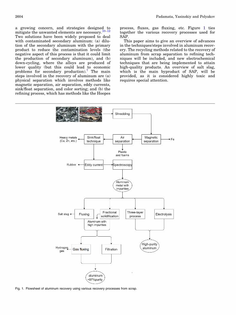
Two solutions have been widely proposed to dealwith contaminated secondary aluminum: (a) dilu-tion of the secondary aluminum with the primaryproduct to reduce the contamination levels (thenegative aspect of this process is that it could limitthe production of secondary aluminum), and (b)down-cycling, where the alloys are produced oflower quality (but this could lead to economicproblems for secondary production).7 The mainsteps involved in the recovery of aluminum are (a)physical separation which involves methods likemagnetic separation, air separation, eddy currents,sink/float separation, and color sorting; and (b) therefining process, which has methods like the Hoopes
process, fluxes, gas fluxing, etc. Figure 1 tiestogether the various recovery processes used forSAP.
This paper aims to give an overview of advancesin the techniques/steps involved in aluminum recov-ery. The recycling methods related to the recovery ofaluminum from scrap separation to refining tech-niques will be included, and new electrochemicaltechniques that are being implemented to attainhigh-quality products. An overview of salt slag,which is the main byproduct of SAP, will beprovided, as it is considered highly toxic andrequires special attention.
Fig. 1. Flowsheet of aluminum recovery using various recovery processes from scrap.
Padamata, Yasinskiy and Polyakov2604
SEPARATION TECHNIQUES
The separation stage is the primary step involvedin SAP. This stage is used to remove metallicresidues such as Fe, Mg, Cu, and Zn and non-metallic ones like rubber, glass, and plastics. Beforethe scrap materials reach recycling plants for theseparation process, the automobiles, householdwaste, and electronics scraps are shredded intopieces. A preheating method is mainly used forhousehold waste, such as cans, to remove plasticcoatings or organic paints before the remeltingprocess. The type of sorting technique implementedto remove the residue depends upon the residuetype. The following are the four main separationtechniques widely used in SAP.
Magnetic Separation
Magnetic separation is implemented to separateferrous and non-ferrous metal scrap. This method isextensively used in SAP. In this process, scrap isplaced on a conveyor which passes near a secondconveyor equipped with a NdFeB magnet. Theferromagnetic materials (iron and steel) present inthe scrap attach to the magnet and are pulled awayby the second conveyor, while the non-ferrousmaterials fall into a container provided for collec-tion. The main limitation of the process is that onlyferrous metals can be separated from the scrapmixture and further separation techniques need tobe performed to remove non-ferrous materials likerubber, plastic, magnesium, copper, etc.13
Air Separation
Lightweight materials such as rubber, plastics,and foams can be removed from the scrap using theair separation method. The recycling materialstream is fed into the vertical air separation systemthrough a column having the air pushing upwards.The light materials are further pushed upwardsusing various feeds while the heavy ones arecollected at the bottom. The main disadvantage isthat lightweight metal components such as sodacans and foils are also separated along with theunwanted impurities, causing metal loss.13 In addi-tion, the impurities collected in this process arelandfilled. Currently, this sorting technique is notwidely used but it is expected to be adopted by mostrecycling plants to obtain metallic scrap streams.14
Sink/Float Method
In this method, a liquid bath containing a finesuspension of water and magnetite is used toseparate materials with differing densities. Thescrap metal stream after the magnetic and airseparations includes impurities such as zinc, mag-nesium, copper, and higher density plastic andrubber. Because these materials have differentdensities (see Table I), the sink/float technique canbe applied to separate aluminum from unwanted
residue. The process contains three steps. The non-metallic materials (foams, rubber, and plastic) areseparated from the metals in water (with a specificdensity of 1) in the first step. In the second step, aslurry with a specific density of 2.5 is used toseparate magnesium from other metals. In the finalstage, slurry with a specific density of 3.2–3.5 isused to separate aluminum from the rest of themetals. The specific density of the slurry is managedby adjusting the quantity of magnetite in theliquid.15 The main disadvantages of this techniqueinclude high maintenance, loss of boat-shaped met-als, and it is not possible to sort aluminum 2000series from 3000 and 5000 series.
Eddy Current
Eddy current separation (ECS) is used to separatenon-ferrous metals from other particles. In ECS, analternative eddy current is induced in the non-ferrous metals when met with a variable magneticfield generated by the rotating NdFeB drum mag-nets. The newly developed magnetic field of theelectrically conductive non-ferrous metals and themagnetic field of the eddy current separator havethe same magnetic field direction. This phenomenonresults in the repulsion of non-ferrous metals,changing the movement of the metals and separat-ing them from other particles. Metals with differenteddy currents are thrown different distances due totheir varying electric conductivity and density. Themetals can be separated by placing the collectors atdifferent distances from the rotor.17 The mainshortcoming of this method is the difficulty inremoving foils and tiny metallic wires as it ischallenging to generate a magnetic field in them.The separation efficiency of this method mainlydepends on three factors: feeding speed, xR� v, andSp
Sm. Here, xR� v is the distance between the feed
speed and rotation speed of the magnetic field; andSp
Smis the ratio between the maximum cross-area of
the metallic flake and the magnet side area facingthe particles. The detachment angle increases withan increase in xR� v and the separation efficiency
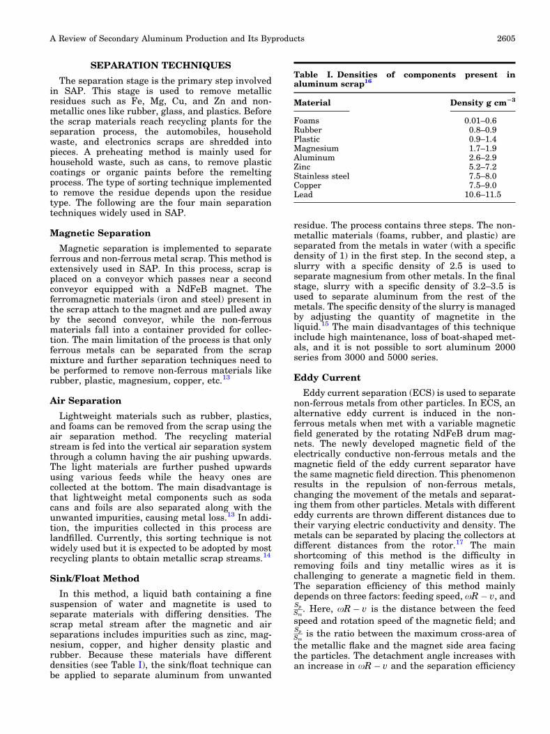
Table I. Densities of components present inaluminum scrap16
Material Density g cm23
Foams 0.01–0.6Rubber 0.8–0.9Plastic 0.9–1.4Magnesium 1.7–1.9Aluminum 2.6–2.9Zinc 5.2–7.2Stainless steel 7.5–8.0Copper 7.5–9.0Lead 10.6–11.5
A Review of Secondary Aluminum Production and Its Byproducts 2605
increases with increasing detachment angle. Sepa-
ration efficiency increases with increasingSp
Sm. The
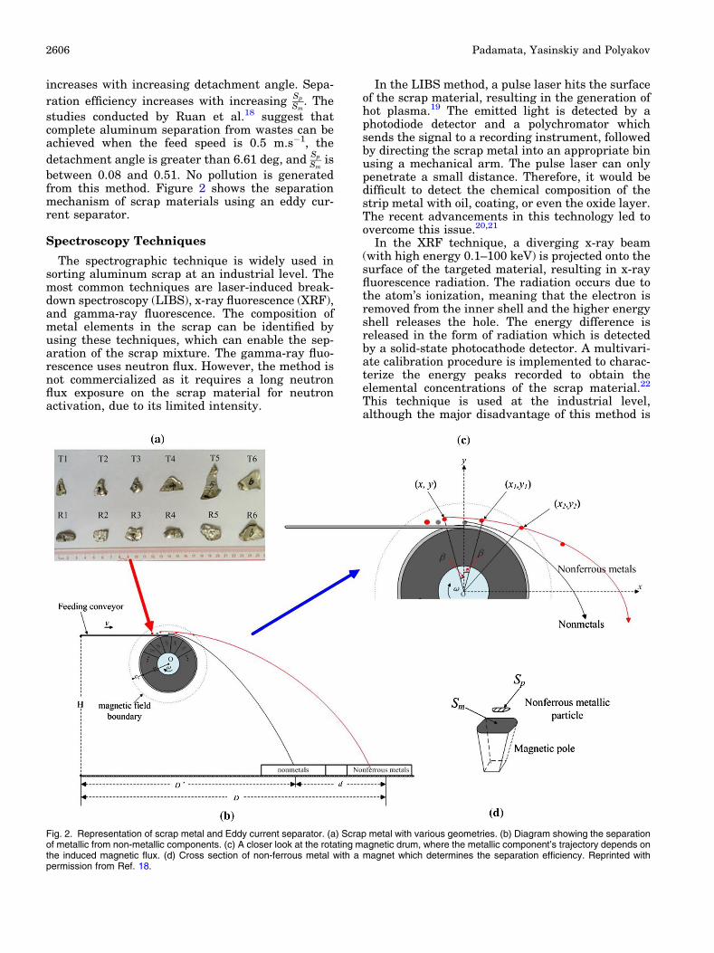
studies conducted by Ruan et al.18 suggest thatcomplete aluminum separation from wastes can beachieved when the feed speed is 0.5 m.s�1, the
detachment angle is greater than 6.61 deg, andSp
Smis
between 0.08 and 0.51. No pollution is generatedfrom this method. Figure 2 shows the separationmechanism of scrap materials using an eddy cur-rent separator.
Spectroscopy Techniques
The spectrographic technique is widely used insorting aluminum scrap at an industrial level. Themost common techniques are laser-induced break-down spectroscopy (LIBS), x-ray fluorescence (XRF),and gamma-ray fluorescence. The composition ofmetal elements in the scrap can be identified byusing these techniques, which can enable the sep-aration of the scrap mixture. The gamma-ray fluo-rescence uses neutron flux. However, the method isnot commercialized as it requires a long neutronflux exposure on the scrap material for neutronactivation, due to its limited intensity.
In the LIBS method, a pulse laser hits the surfaceof the scrap material, resulting in the generation ofhot plasma.19 The emitted light is detected by aphotodiode detector and a polychromator whichsends the signal to a recording instrument, followedby directing the scrap metal into an appropriate binusing a mechanical arm. The pulse laser can onlypenetrate a small distance. Therefore, it would bedifficult to detect the chemical composition of thestrip metal with oil, coating, or even the oxide layer.The recent advancements in this technology led toovercome this issue.20,21
In the XRF technique, a diverging x-ray beam(with high energy 0.1–100 keV) is projected onto thesurface of the targeted material, resulting in x-rayfluorescence radiation. The radiation occurs due tothe atom’s ionization, meaning that the electron isremoved from the inner shell and the higher energyshell releases the hole. The energy difference isreleased in the form of radiation which is detectedby a solid-state photocathode detector. A multivari-ate calibration procedure is implemented to charac-terize the energy peaks recorded to obtain theelemental concentrations of the scrap material.22
This technique is used at the industrial level,although the major disadvantage of this method is
Fig. 2. Representation of scrap metal and Eddy current separator. (a) Scrap metal with various geometries. (b) Diagram showing the separationof metallic from non-metallic components. (c) A closer look at the rotating magnetic drum, where the metallic component’s trajectory depends onthe induced magnetic flux. (d) Cross section of non-ferrous metal with a magnet which determines the separation efficiency. Reprinted withpermission from Ref. 18.
Padamata, Yasinskiy and Polyakov2606

that it is difficult to analyze the accurate concen-tration of aluminum alloys containing low atomicnumber elements such as lithium, beryllium, boron,or magnesium.21
The techniques mentioned above are extensivelyused to separate scrap materials to obtain high-quality aluminum scrap for the refining process.However, the sequence and the processing method-ology may vary depending upon the scrap materialtype and quality of produced secondary aluminum.
ALUMINUM REFINING
Aluminum refining involves the removal of dis-solved impurities present in the aluminum scrapmetal. Researchers aim to find energy-efficient aswell as environmentally friendly methods for alu-minum refining. The most popular method used foraluminum refining is fluxing, while there has been arecent focus on electrolysis methods such as low-temperature electrolysis and the thin-layer refiningprocess. The selective melting technique is gener-ally used on aluminum scrap metals containingweld joints with metals such as Sn (232�C), Pb(327�C), and Zn (419�C) having lower meltingtemperatures than aluminum (660�C). The furnacetemperature is set to the melting temperature of themetals mentioned above, and the contaminants areremoved before finally recovering the aluminummetal.
Remelting and Fluxing
In the remelting process, pure aluminum isinitially heated at around 800�C, followed by theaddition of metal scrap. It is sometimes challengingto maintain the operating temperature as cold scrapmetal is fed in periodically. The dross on top of themetal bath is skimmed continuously. In Eggenet al.,23 the remelting process was performed torecover aluminum from household waste (cans andfoils). Pre-treatment, such as thermal decoating,compacting, and sizing was performed on householdwaste before remelting. Decoating temperatureswere 300�C and 550�C and were held till the processwas complete (till the smoke stopped). Decoatingcans at 550�C compared with 300�C producedhigher yield, low Mg and Pb content, and cleanermelt with a low oxide scale inclusion area. Whilecans can be recycled with acceptable yield and metalquality, foils had a negative yield and cannot berecycled.
Nakajima et al.24 conducted a thermodynamicsimulation study to estimate the possibility of theremoval of an impurity element (M) through theremelting process. The 45 elements that are mostcommonly found in scrap metal were studied tounderstand their equilibrium distribution ratiosamong metals, slag, and gas phase. The distributionof impurity elements among molten metal and oxideslag can be quantified by equilibrium constants ofoxidation and evaporation processes. The
distribution coefficient determines the removal ofimpurities from the solvent metal. For oxidation ofM from the solvent metal, reaction (1) takes place:
mM þ n
2O2 ¼ MmOn ð1Þ
where the equilibrium constant K¢¢ is given by Eq. 2
K 0 ¼ aMmOn
aMmP
n2
O2
¼cMmOn
xMmOn
ðcMxMÞmPn2
O2
ð2Þ
where PO2is the oxygen partial pressure (Pa),
aMmOn, cMmOn
; and xMmOnare the activity in the
Raoultian standard state (pure solid oxide); theactivity coefficient; and the mole fraction of oxideMmOn distributed into slag phase by oxidation.
By rearranging Eq. (2), the distribution ratio of Mbetween slag and metal can be obtained:
L0 ¼ xMxMmOn
¼cMmOn
K 0cmMxm�1M P
n2
O2
ð3Þ
In the case of M evaporation from solvent metal:
M ¼ MðgÞ ð4Þ
The equilibrium constant is defined by the follow-ing equation:
K ¼ PM
aM¼ PM
cMxM¼ Po
M ð5Þ
where PoM, PM;aM, cM and xM are the partial
pressure of pure element M (Pa), partial pressureof M in the alloy (Pa), the activity of M in theRaoultian standard state (a pure liquid substance),the activity coefficient of M, and the mole fraction ofM, respectively.
The distribution coefficient of M between metaland gas phase is as follows:
L00 ¼ PM
PAl¼ Po
McMxMPAl
ð6Þ
A smaller L¢ value corresponds to easier removalof M into the slag phase by oxidation and largervalues of L¢¢ result in easier removal of M byevaporation.
Figure 3 shows the distribution ratios of impuri-ties in three different phases during the remeltingprocess. The figure shows that Mg, Ca, and Be canbe removed by oxidation and transferred to the slag,while Zn, Hg, and Cd can be evaporated. The otherelements remain in the metal and are difficult toremove. In reality, aluminum recycling in indus-tries is additionally affected by different parameterssuch as the fluidity of the metal bath, temperaturedistribution in the furnace, and non-uniformity ofthe gas phase.
Fluxing is the most commonly practiced tech-nique for SAP. It is similar to the remelting processbut with the addition of salt flux. In this process, a
A Review of Secondary Aluminum Production and Its Byproducts 2607

high-temperature furnace is charged with moltensalt used as flux, along with the scrap metal. Themetal scrap is mechanically submerged as soon aspossible to avoid metal oxidation and salt loss. Theadvantages of using this technique include (1)reduction of metal oxidation, (2) increased fluidityof the melt to encourage the separation of inclu-sions, (3) migration of impurities into the dross, and(4) removal of hydrogen and nitrogen gases from theliquid metal. The metallic impurities like Mg, Na,Li, Ca, etc. react with molten salt to formstable metallic chlorides which are removed in theform of a sedimented mixture or the dross, depend-ing upon its density.25 Sodium chloride and potas-sium chloride are the most commonly used salts forfluxing due to their low melting point and low cost.26
CaF2, NaF, and Na3AlF6 are the common fluoridesalts used as additives in the flux to improve thecoalescence of the metal.27–29 The salt flux promotesthe stripping of the oxide layers on the aluminummetal, having a mechanism similar to the hotcorrosion process, and improves coalescencebetween aluminum droplets.30 According to Royand Sahai,31 the three steps involved in the strip-ping of the oxide layer from the liquid metal are: (1)openings developing in the oxide layer, (2) saltpenetration between metal and oxide, and (3) oxidelayer stripping and formation of dross/slag whichimproves metal yield.
In some cases, fluxing requires large volumes ofsalts to remove impurities. For instance, about 2.95kg of salt is required to remove 1 kg of magnesium.Utigard et al.25 state that about 120 kg of chlorinegas is required to remove Mg from 1 metric ton of
wrought 5XXX or 6XXX aluminum scrap metal.This would result in high amounts of chlorine andfluorine gas utilization, which must be captured andtreated. The main advantage of fluxing over remelt-ing is that the salt flux can break the thick oxidelayer on the metal and improve metal coalescence.32
Low-Temperature Electrolysis
High purity aluminum was produced by Huanet al. through low-temperature electrolysis using acoarse Al–Si alloy as a dissolving anode (170�C).33
An Al–Si-based anode with the main impuritiesbeing Fe, Ca, Ti, Mg, and Mn, and an aluminumsheet cathode were used in this method. Theelectrolyte composition by mass percentage wasAlCl3 : NaCl: KCl = 66:20:14, and aluminumchloride was dried in a HCl atmosphere to reducethe moisture in the electrolyte. Potentiostatic elec-trolysis was performed between 0.3 and 0.7 V. Theelectrochemical reduction potential of ions in theelectrolyte was in the order Fe > Si > Al > Mg >Ca. At an electrode potential between 0.4 and 0.7 V,Fe and Si dissolved electrochemically from theanode. In particular, the Si content (wt.%) wasaround 0.77% in the reduced aluminum. At elec-trode potentials below 0.3 V, only Mg, Ca, and Alwere dissolved, while only aluminum was reducedat the cathode surface. Thus, aluminum purity ofabout 99.9% was achieved when the electrodepotential was at or below 0.3 V. This techniquecan be used on impure aluminum alloys produced bythe recycling process to obtain high-qualityaluminum.
Fig. 3. Distribution of elements between metal, slag, and gas phases for simulated aluminum remelting. Reproduced with permission from Ref.24.
Padamata, Yasinskiy and Polyakov2608
The aluminum in the anode is dissolved in theelectrolyte in the form of Al2Cl
�7 and AlCl�4 while the
electrodeposition of aluminum on the cathode is bythe following reactions:34
4Al2Cl�7 þ 3e� ! Alþ 7AlCl�4 ð7Þ
AlCl�4 þ 3e� ! Alþ 4Cl� ð8Þ
The current efficiency was around 94%, and highaluminum purity can be attained at low energyconsumption by using low-temperature electrolysis.
Fractional Solidification
In this process, the materials are processed in theirsemi-solid state with solutes separated between solidand liquid phases. In the case of aluminum scrapmetals, the material is initially transformed into aliquid state followed by rapid cooling of the meltsurface for the formation of aluminum crystals.These solidified pieces are deposited in the bottomof the furnace. If the solubility of the solutes (impu-rities) is higher in the liquid phase than in the solidphase, the aluminum crystals will reject the dissolvedimpurity enriching the liquid phase. Therefore, theliquid aluminum with high levels of impurities isremoved while the solidified, high purity, aluminumremains in the furnace for remelting and is thenremoved. We can estimate the impurity removal levelby considering the binary phase diagram and thethermodynamic distribution coefficient (k). Theequation proposed by Kahveci and Unal35 to estimatethe thermodynamic distribution coefficient (k) is asfollows:
k ¼ Csoluteinsolid
Csoluteinliquidð9Þ
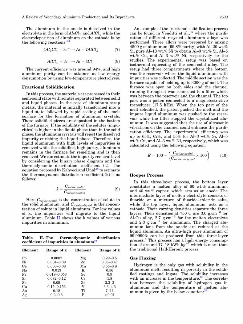
Here Csoluteinsolid is the concentration of solute inthe solid aluminum, and Csoluteinliquid is the concen-tration of solute in liquid aluminum. For low valuesof k, the impurities will migrate to the liquidaluminum. Table II shows the k values of variousimpurities in aluminum.
An example of the fractional solidification processcan be found in Venditti et al.,37 where the purifi-cation of different recycled aluminum alloys wasperformed. Three alloys were prepared by mixing4500 g of aluminum (99.8% purity) with Al–20 wt.%Si, pure Al–13 wt.% Ni to obtain Al–3 wt.% Si, Al–5wt.% Cu, and Al–3 wt.% Ni, respectively for thestudies. The experimental setup was based onisothermal squeezing of the semi-solid alloy. Thesetup had three compartments where the bottomwas the reservoir where the liquid aluminum withimpurities was collected. The middle section was thefurnace capable of holding up to 3000 g of melt. Thefurnace was open on both sides and the channelrunning through it was connected to a filter whichwas between the reservoir and the channel. The toppart was a piston connected to a magnetostrictivetransducer (17.5 kHz). When the top part of themelt solidified, the piston pushed the melt and theimpure liquid aluminum was pushed to the reser-voir while the filter stopped the crystallized alu-minum. It was suggested that the use of ultrasonicvibrations on the channel could enhance the purifi-cation efficiency. The experimental efficiency wasup to 65%, 62%, and 55% for Al–3 wt.% Si, Al–5wt.% Cu, and Al–3 wt.% Ni, respectively, which wascalculated using the following equation:
E ¼ 100 � Csoluteinsolid
Csoluteinoriginal� 100
� �ð10Þ
Hoopes Process
In this three-layer process, the bottom layerconstitutes a molten alloy of 60 wt.% aluminumand 40 wt.% copper, which acts as an anode. Theintermediate layer of molten electrolyte consists offluoride or a mixture of fluoride–chloride salts,while the top layer, liquid aluminum, acts as acathode. Their varying densities separate the threelayers. Their densities at 750�C are 3.0 g.cm�3 forAl-Cu alloy, 2.7 g.cm�3 for the molten electrolyteand 2.3 g.cm�3 for aluminum. The charged alu-minum ions from the anode are reduced at theliquid aluminum. An ultra-high pure aluminum of99.9999% can be produced from this three-layerprocess.8 This process has a high energy consump-tion of around 17–18 kWh.kg�1 which is more thanthe traditional Hall-Heroult process.
Gas Fluxing
Hydrogen is the only gas with solubility in thealuminum melt, resulting in porosity in the solidi-fied castings and ingots. The solubility increaseswith an increase in the temperature.38 The correla-tion between the solubility of hydrogen gas inaluminum and the temperature of molten alu-minum is given by the below equation:39
Table II. The thermodynamic distributioncoefficient of impurities in aluminum36
Element Range of k Element Range of k
Pb 0.0007 Mg 0.29–0.5Ni 0.004–0.09 Zn 0.35–0.47Ca 0.006–0.08 Mn 0.55–0.9Na 0.013 K 0.56Fe 0.018–0.053 Sc 0.9Si 0.082–0.12 Cr 1.8Sb 0.09 Zr 2.3–3Cu 0.15–0.153 V 3.3–4.3Au 0.18 Ti 7–11Ag 0.2–0.3 P <0.01
A Review of Secondary Aluminum Production and Its Byproducts 2609

logS ¼ � 2692
Tþ 2:726 ð11Þ
S is the solubility of hydrogen gas (cc. 100 g�1)and T is the thermodynamic temperature (degreeKelvin). The solubility of hydrogen gas doubles foreach 110�C increase in melt temperature.
The hydrogen gas, along with some inclusions andalkali can be removed using the gas fluxing process.In this process, gas (usually chlorine or argon) isinjected at the bottom of the melt containingimpurities. The hydrogen atoms and alkali diffuseon the bubble surface, resulting in the bubble’sexpansion by the hydrogen gas and the alkali. Whenthe bubble reaches the surface, the hydrogen gas isreleased while the alkali migrates to the dross. Ingeneral, the gas is injected through a rotatingimpeller to increase the probability of collisionbetween the gas bubbles and the inclusions.40 Thedegassing efficiency is 100% when the bubbles aresaturated with hydrogen gas. However, as thehydrogen gas content drops, the pressure of thehydrogen decreases in the bubbles. This wouldrequire more inert anode gas pumping for theremoval of low H2 concentrations from the metal.41
Equation (12) defines the gas removal ratio (R),which is the volume of inert gas needed to remove 1l of hydrogen from the metal. At one atm pressure,R for pure aluminum at 750� is given as:
R ¼ 1 � Pð ÞP
¼ S:C
H
� �2
� 1 ð12Þ
Here, S is the solubility of hydrogen in moltenmetal, P is the pressure of hydrogen vapor, C is thecorrection factor, and H is the amount of gasdissolved in molten metal. An increase in the melttemperature would increase the solubility of thehydrogen gas and gas removal ratio. Thus, the melttemperature should be lower to achieve highdegassing efficiencies.
Filtration
Filtration is a mechanical process used to removethe inclusions when liquid metal is passed througha ceramic foam filter (CFF) which is the mostcommon filter type used in aluminum production.The interaction between the inclusions and a filtersurface is an important parameter, where selectivecapture of inclusions can be done through chemicalbonding, friction, and electrostatic forces. Forinstance, AlF3 based filters could remove Na andMg impurities from liquid aluminum by convertingthem to NaF and MgF2.42 Inclusions and particlesare stopped at the filter and accumulate, resultingin the formation of a cake, and the filtration abilityimproves when the cake gets thicker. High filtrationefficiency can be achieved with better filter surfacewettability, and the SiC foam filter showed betterfiltration efficiency than Al2O3 filters. SiC materialhas a lower wetting angle of 39 deg compared with
Al2O3 material with a wetting angle of 84 deg.43 Theporosity and depth of the filters also influence thefiltration efficiency.44 A liquid metal cleanlinessanalyzer (LiMCA) and porous disk filtration appa-ratus (PoDFA) are used to characterize the filtrationefficiency of filters.45 The filtration efficiency of aCFF follows an exponential law as shown inEq. (13), as verified in:46
E0 ¼ 1 � expð�k0LÞ ð13Þ
where E0 is the initial filtration efficiency, k0 is theinitial filtration coefficient, and L is the filterthickness.
Gauckler et al.47 described the influence of vari-ous filtration parameters on filtration efficiency;these are included in Table III.
The study conducted by Damoah and Zhang48
showed that a 30-ppi CFF can remove almost allinclusions with size > 125 lm and up to 85% ofinclusions with size � 5 lm from aluminum. Fluiddynamics modeling suggests that the larger inclu-sions are entrapped at the top-most part of the filterwhile the smaller ones are dispersed throughout thefilter. The calculated interfacial energy between twocolliding inclusions indicates that the particlesexhibit a strong attraction force between themwhich holds the particles together. This explainswhy the small inclusions can be filtered during theprocess. The formation of intermetallic and non-metallic inclusions bridges during filtrationenhance the filtration efficiency by accumulatingthe finer inclusions. This attraction between theinclusions is only effective when the molten metaltemperature is below 900�C.
Other than CFF, a deep-bed filter (DBF) is widelyused at an industrial scale for aluminum filtration.This filter consists of a packed bed of refractoryparticles [alumina tabs (25 cm) or alumina balls (2cm)] through which the molten metal flows. Theinclusions are deposited on the grains of the filtermedium due to gravity, diffusion, surface forces,and direct interception. The inclusions larger than30 lm are filtered due to mechanical entrapmentphenomena, while surface forces are responsible forremoving inclusions smaller than 30 lm frommolten aluminum. Flow dynamics play a significantrole in the transportation of smaller inclusions tothe grain surfaces of filter media. Having a largesurface area enables the DBF to trap inclusionsmuch smaller than the pores of the filter bed. A DBFis suitable for continuous casting operations due toits long life cycle. However, the filters are costly torefurbish and work slowly at the end of their life. Itis worth noting that the alumina tabs show highfiltration efficiency compared with alumina balls athigh melt velocities.49
Flotation and filtration processes are used afterthe remelting process to improve the quality of therecycled aluminum and can be considered underliquid aluminum treatments.
Padamata, Yasinskiy and Polyakov2610

Salt Cake
Salt cake/salt slag is the main waste generatedfrom SAP, which contains a mixture of aluminumand metal oxides along with slag. When the saltcake is exposed to liquids, it releases toxic gases andsoluble ions.50,51 It is considered as hazardous as itis highly flammable. Usually, rather than recyclingor treating the slag cake, they are directly land-filled. For instance, around one million tons of saltcake was landfilled in the USA.52
In the rotary melting furnace process, the furnaceis charged with metal scrap/dross and salt flux(generally up to 50% of the feed). The metal isprotected by the salt and it further facilitatesagglomeration and separation, resulting inimproved metal recovery.53 In addition, the moltensalt prevents the liquid metal from getting oxidized,and avoids metal contamination by absorbing theoxides and unwanted non-metallic substances. Thealuminum metal and molten salt flux are tappedafter the process, where the cooled flux along withthe mixture of non-metallic components is calledsalt slag or salt cake.54 Salt slag contains 5–7 wt.%residual aluminum metal, 15–30 wt.% aluminumoxide, 30–55 wt.% sodium chloride, and 15–30 wt.%potassium chloride and, depending upon the type ofscrap added, carbides, nitrides, phosphides, andsulphides are also present.55
The salt cake is considered highly toxic, environ-mentally hazardous, and its disposal is problematicworldwide. Improper disposal of salt cakes whilelandfilling could lead to the reaction of its toxicmetal ions with groundwater, resulting in environ-mental concerns.56 The highly toxic and poisonousgases such as NH3, H2S, PH3; and CH4 are formedwhen the salt cake interacts with water. Ammoniagas is produced from the hydrolysis of nitridespresent in the salt cake:57–59
AlN þ 3H2O ! NH3 þ Al OHð Þ3 ð14Þ
AlN þ 4H2O ! NH4OH þ Al OHð Þ3 ð15Þ
NH3 þH2O ! NH4OH ð16Þ
Ammonia is highly soluble in water, increasingthe pH value up to 9 and making the environmentalkaline. At high pH values, the aluminum metalreacts with water and results in the formation of H2
and Al2O3 as shown in Eq. (17). The hot H2 reactswith air (O2) and combustion takes place.
2Alþ 3H2O ! 3H2 þ Al2O3 ð17Þ
Methane evolution takes place when aluminumcarbide present in the salt cake reacts with water:
Al4C3 þ 6H2O ! 3CH4 þ 2Al2O3 ð18Þ
An increase in the pressure and heat under thelandfill could also lead to the reaction of aluminumcarbide with nitrogen gas present in the soil togenerate aluminum cyanide, and with eventualhydrolysis of aluminum cyanide could form HCN:
2Al4C3 þ 6N2 þ 9C ! 4Al CNð Þ3 ð19Þ
4Al CNð Þ3 þ 6H2O ! 12HCN þ 2Al2O3 ð20Þ
From the above reactions, it is clear that thedisposal of salt slags in hazardous landfills couldpollute the groundwater (increasing pH,F�;Cl�;andNHþ
4 ). It is getting much harder toopen new landfills due to increasing environmentalpressures, and recycling/treating them could be theultimate solution.
The NaCl/KCl salts in the slag can be converted tovalue-added materials by employing the dechlori-nation process using weak-based, anion-exchangeresin.60 The process chemistry is shown as follows:
Carbonation:
R:OH þ CO2 ! R:HCO3 ð21Þ
Dechlorination:
Table III. Filtration parameters affecting filtration efficiency
Filtration parameter
Filtration efficiency
High Low
Particles High specific densityLarger size
Low specific densitySmaller size
Liquid flow Steady flowLaminar flow in the filter medium
Low melt velocity
Turbulent flow in the filter mediumHigh melt velocity
Filter medium Large internal surfaceSmall window size [pores per inch (ppi)]
Small internal surface
A Review of Secondary Aluminum Production and Its Byproducts 2611

R:HCO3 þNaCl=KCl ! R:ClþNaHCO3=KHCO3
ð22Þ
Regeneration:
R:ClþNH4OH ! R:OH þNH4Cl ð23Þ
R is the complex cation group in the resin. It is aweak-base, anion exchange resin that is either thefree base or hydroxide form. The active sites of theresin must be converted to bicarbonate form beforeimplementing dechlorination of slag material. Asshown in Eq. (21), the hydroxide-based resin iscarbonated by treating with carbonated water tosynthesize active bicarbonate groups. The resin (R.HCO3) is then exhausted by an alkali metal chloridesolution, as shown in Eq. (22). The exhausted R.Cl isregenerated to R.OH according to Eq. (23), using aNH4OH solution. The chloride ions’ removal effi-ciency increases with a decrease in the ratio of slagsolution to resin. The NH4Cl can be concentratedand sold as a chemical or can be further used torecover NH3 at an operating temperature of 200�Cas shown below:
NH4ClþH2O ! NH4OH þHCl ð24Þ
In this way, sodium- and potassium-based saltsfrom the slag material can be recovered and couldreduce the volume of materials going to the landfill.The level of highly water-soluble materials in theslag will be reduced so that cheaper and unlinedlandfills can be used. Moreover, the recovered saltscan be reused in the processing smelters, or can becommercially sold.
The treatment process for the salt cake containssteps like (a) crushing and screening, (b) waterleaching/ filtering, (c) gas elimination, and (d)evaporation/crystallization. Initially, the slag iscrushed through milling, and metallic aluminumis separated by screening. Many companies processsalt cake through wet milling, which would enrichthe metallic concentrate and produce oxides andbrine byproducts.61 The milled slag powder is thenwater leached, where a slurry is obtained whichcontains few grains of aluminum. These grains areremoved utilizing a rotating screen and then finallydried. The remaining oxides slurry is filteredthrough a continuous vacuum belt filter, where thechlorides are intensely drained from the oxidescake. The obtained cake has a very low chloridecontent (< 0.2%) and can be employed in theconstruction industry as cement. The gases released
Table IV. A summary of various aluminum slag (dross) treatments
Techniques used Remarks Ref.
Plasma arc melting The plasma arc melting process was used to obtain c-alumina powder. At a plasma levelof 15 kW, a maximum of 21% of raw dross could be converted into ultrafine Al2O3 powder
63
Sintering and leaching About 90% of alumina was recovered from the dross using a soda roast–dilute causticleaching route. All the chemicals used in this process can be recycled, hence cost-efficient
64
Sintering and hydraulicpressing
Hercynite (FeAl2O4) was synthesized by using aluminum dross and iron at 1550�C.Results in avoiding the landfilling of the dross
65
Plasma spray coating Al2O3 and MgAl2O4 compounds were coated on tundish and Inconel substrates usingplasma spray techniques. The implication to be used as a refractory coating (heat
insulation). Unwanted AlN semi-conductive phase was removed
66
Leaching Aluminum dross treatment by leaching with NaOH and H2SO4 aqueous solutionsresulting in the synthesis of tamarugite [NaAl(SO4)2.6H2O]. The applications for
tamarugite have not yet been established
67
Sintering Magnesium aluminum titanate-based ceramics with high-temperature applicationswere synthesized by sintering aluminum dross and rutile ore at 1300�C for 6 h.
68
Sintering Aluminum dross and coal fly ash were used to prepare mullite-based ceramics throughsintering and acid leaching methods. At a sintering temperature of 1500�C, high mullite
content ceramics with good crystallinity were obtained
69
Leaching Mg–Al, Ca–Al, and Zn–Al type layered double hydroxides synthesis by leachingaluminum dross with HCl and NaOH solution, mixing with magnetic stirring
70
Ball-milling, hydrolysis H2 production by hydrolysis of ball-milled aluminum dross using tap water. 100%hydrogen yield
71
Leaching Al was separated from Al dross by using HCl leachate. The recovery rate was up to 22% 72Leaching, sintering, andcalcining
Al2O3 and MgAl2O4 based refractory material was successfully synthesized by removingAlN through aqueous solution leaching. After a calcining process, the sample color
turned to white from black
73
Leaching, hydrolysis Cl, F, and AlN were removed by the hydrolysis process. AlN hydrolysis can be performedat room temperature, and the activation energy of AlN was 38.64 kJ mol�1. Therefore,the leaching residues containing 43.10% of aluminum can be used as a substitute for
bauxite
74
Padamata, Yasinskiy and Polyakov2612
in the leaching process are burnt in a combustor,where the toxic ones are converted to inert gasesand water. The heat produced during the combus-tion of pollutants is used as an energy source for thesingle or multistage crystallizer where the salts arerecovered in the form of crystals.62
The non-metallic residues can be utilized in thefollowing applications:62
� In the chemical industry: production of alu-minum salts and hydrated aluminum oxide,epoxy resin mortar, inert load in polymers.
� In agriculture: fertilizers, artificial soil.� In the metallurgical industry: synthetic steel
refining slags to remove phosphorus, sulfur, andaluminum oxide from molten steel.
� In civil works: inert filling for constructions,mortar components, pavements.
� Mineral wool.
Table IV summarizes some of the processes used torecycle the aluminum slag through which value-added materials can be recovered.
CONCLUSION
This paper discusses the recycling of aluminum aswell as the utilization of salt slag generated fromprimary and secondary aluminum production. Var-ious pre-refining steps and refining steps have beendiscussed in brief. Recycling aluminum can solvetwo issues at once: the demand for aluminum metaland the environmental issue. The refining processesneed to be energy efficient and environmentallyfriendly. Remelting and fluxing are widely usedindustrially, and have a high metal yield, althoughthese processes generate high volumes of environ-mentally hazardous salt slag. This would requiretreatment/utilization of the slag to avoid landfilling(which makes the environment alkaline). TheHoopes process requires more energy than the onerequired for primary aluminum production. On theother hand, SAP through electrolysis is promising,and a lot of work is being done in this area. Theconventional treatment for salt slag recoveryincludes slag grinding, recovery of metal particlesby sieving followed by leaching (with water) todissolve the salt in water, then filtering and evap-oration. The non-metallic residues can be landfilledor used to prepare cement, refractory, and ceramicapplications, or be used in metallurgical and chem-ical industries. This could eventually reduce thelandfilling cost and would be environmentallyfriendly.
CONFLICT OF INTEREST
On behalf of all authors, the corresponding authorstates that there is no conflict of interest.
ACKNOWLEDGEMENTS
The reported study was funded by RFBR accord-ing to the research project No 18–29–24122.
FUNDING
Open Access funding enabled and organized byProjekt DEAL.
OPEN ACCESS
This article is licensed under a Creative CommonsAttribution 4.0 International License, which per-mits use, sharing, adaptation, distribution andreproduction in any medium or format, as long asyou give appropriate credit to the original author(s)and the source, provide a link to the CreativeCommons licence, and indicate if changes weremade. The images or other third party material inthis article are included in the article’s CreativeCommons licence, unless indicated otherwise in acredit line to the material. If material is not in-cluded in the article’s Creative Commons licenceand your intended use is not permitted by statutoryregulation or exceeds the permitted use, you willneed to obtain permission directly from the copy-right holder. To view a copy of this licence, visit http://creativecommons.org/licenses/by/4.0/.
REFERENCES
1. H. Kvande. Fundamentals of Aluminium Metallurgy: Pro-duction, Processing, and Applications, ed. R. Lumley(Cambridge, Woodhead Publishing Limited, 2010), pp. 49–69 (2010).
2. M. Gautam, B. Pandey, M. Agrawal, Environmental CarbonFootprints, ed. S. S. Muthu (Oxford, Butterworth-Heine-mann, 2018), pp. 197–228.
3. H. Kvande, and W. Haupin, JOM 53, 29. (2001).4. Bureau of International Recycling (BIR) Annual report
2019, link: https://www.bir.org/publications/annual-reports/download/648/1000000235/36?method=view (Accessed on 3March 2021).
5. A.S. Yasinskiy, S.K. Padamata, P.V. Polyakov, and A.V.Shabanov, Non-Ferrous Met. 2020(1), 15. (2020).
6. J. Green, Aluminum Recycling and Processing for EnergyConservation and Sustainability, ed. J. Green (ASM Inter-national, 2007), p. 220.
7. G Gaustada, E. Olivetti, R. Kirchain, Resour., Conserv. Re-cycl. 58, 79 (2012).
8. M. Kondo, H. Maeda, and M. Mizuguchi, JOM 42, 36. (1990).9. European Aluminium Association, link: https://www.euro
pean-aluminium.eu/policy-areas/recycling-circular-economy/ (Accessed on 3 March 2021).
10. G. Gaustad, E. Olivetti, and R. Kirchain, J. Ind. Ecol. 14,286. (2010).
11. S.K. Das, Light Metals, ed. T.J. Galloway, (San Antonio,TMS, 2006), p. 911.
12. A. Gesing, JOM 56, 18. (2004).13. M.A. Reuter, K. Heiskanen, U. Boin, A. Van Schaik, E.
Verhoef, Y. Yang, and G. Georgalli, The Metrics of Materialand Metal Ecology: Harmonizing the Resource, Technologyand Environmental Cycles, 1st edn. (Elsevier, Amsterdam,2005), pp 373–390.
14. S. Capuzzi, and G. Timelli, Metals 8, 249. (2018).15. D.B. Spencer, JOM 57, 46. (2005).16. M.E. Schlesinger, Aluminum Recycling, 1st edn. (CRC
Press, Boca Raton, 2007), pp 71–75.17. G.H. Nijhof, Resou. Conserv. Recycl. 10, 161. (1994).18. J. Ruan, L. Dong, J. Zheng, T. Zhang, M. Huang, and Z. Xu,
Waste Manag. 60, 84. (2017).19. P. Werheit, C. Fricke-Begemann, M. Gesing, and R. Noll, J.
Anal. At. Spectrom. 26, 2166. (2011).20. R. Noll, C. Fricke-Begemann, S. Connemann, C. Meinhardt,
and V. Sturm, J. Anal. At. Spectrom. 33, 945. (2018).
A Review of Secondary Aluminum Production and Its Byproducts 2613

21. S. Piorek, Mater. Today: Proc. 10, 348. (2019).22. R. Schramm, Phys. Sci. Rev. 1, 20160061. (2016).23. S. Eggen, K. Sandaunet, L. Kolbeinsen, A. Kvithyld, Light
Metals, ed. A. Tomsett, (San Diego, TMS, 2020), p. 1091.24. K. Nakajima, O.Takeda, T. Miki, K, Matsubae, S. Naka-
mura, T. Nagasaka, Environ. Sci. Technol. 44, 5594 (2010).25. T.A. Utigard, K. Friesen, R.R. Roy, J. Lim, A. Silny, and C.
Dupuis, JOM 50, 38. (1998).26. P.N. Crepeau, M.L. Fenyes, and L.J. Jeanneret, Mod. Cast.
82, 28. (1992).27. Y. Xiao, and M.A. Reuter, Miner. Eng. 15, 963. (2002).28. Y.S. Kim, E.P. Yoon, K.T. Kim, W.J. Jung, and D.H. Jo, J.
Kor. Fou. Soc. 20, 39. (2000).29. R.D. Peterson, Second international symposium—recycling
of metals and engineered materials, ed. J.H. Van Linden, L.Donald, J. Stewart, Y. Sahai, (Pittsburgh, TMS, 1990), p. 69.
30. J.A.S. Tenorio, and D.C.R. Espinosa, J. Light. Met. 2, 89.(2002).
31. R.R. Roy, and Y. Sahai, Mater. Trans. 38, 995. (1998).32. M. Gokelma, I. Meling, E. Soylu, A. Kvithyld, G. Tranell,
Light Metals, ed. C. Chesonis, (San Antonio, TMS, 2019), p.1359.
33. S. Huan, Y. Wang, K. Liu, J. Peng, Y. Di, J. Electrochem.Soc. 167, 103503 (2020).
34. S. Huan, Y. Wang, J. Peng, Y. Di, B. Li, L. Zhang, Miner.Eng. 154, 106386 (2020).
35. A.I. Kahveci, A. Unal, Recycling of Metals and EngineeredMaterials, ed. D.L. Stewert, J.C. Daley, R.L. Stephens,(TMS, 2000), p. 919.
36. D.C. Curtolo, S. Friedrich, D. Bellin, G.S. Nayak, and B.Friedrich, Metals 7, 341. (2017).
37. S.Venditti, D. Eskin, A. Jacot, Light Metals, ed. A. Tomsett,(San Diego, TMS, 2020), p. 1110.
38. R.Y. Lin, and M. Hoch, Metall. Trans. A 20A, 1785. (1989).39. G.K. Sigworth, Essential Readings in Light Metals, (TMS,
2016), p. 226.40. O. Mirgaux, D. Ablitzer, E. Waz, and J.P. Bellot, Metall.
Mater. Trans. B. 40B, 363. (2009).41. G.K. Sigworth, E.M. Williams, D.C. Chesonis, Essential
Readings in Light Metals, (TMS, 2016), p. 65.42. H. Gorner, M. Syvertsen, E.J. Ovrelid, T.A. Engh, Light
Metals, ed. H. Kvande, (San Francisco, TMS, 2005), p. 939.43. M. Syversen, A. Kvithyld, S. Bao, A. Nordmark, A. Jo-
hansson, Light Metals. ed. J. Grandfield, (San Diego, TMS,2014), p. 1041.
44. N.J. Keegam and J.M. McCollum, Light Metals, ed. E.R.Cutshall, (San Diego, TMS, 1992), p. 1086.
45. C. Voigt, E. Jackel, F. Taina, T. Zienert, A. Salomon, G.Wolf, C.G. Aneziris, and P.L. Brun, Metall. Mater. Trans. B.48B, 497. (2017).
46. E. Lae, H. Duval, C. Riviere, P. Le Brun, J.-B. Guillot,Essential Readings in Light Metals, (TMS, 2016), p. 285.
47. L.J. Gauckler, M.M. Waeber, C. Conti, M. Jacob–Duliere,Essential Readings in Light Metals, (TMS, 2016), p. 251.
48. L.N.W. Damoah, and L. Zhang, Metall. Mater. Trans. B.41B, 886. (2010).
49. R. Mutharasan, D. Apelian, and C. Romanowski, JOM 33,12–18. (1981).
50. T.W. Unger, and M. Beckmann, Light Metals (TMS, SanDiego, 1992), p 1159.
51. G.V. Calder and T.D. Stark, J. Hazard., Toxic Radioact.Waste, 14, 258 (2010).
52. TAA, Aluminum—The Element of Sustainability, (TheAluminum Association, Washington D. C., 2011),pp. 70.
53. N. Unlu, M.G. Drouet, Resour., Conserv. Recycl. 36, 61(2002).
54. L. Zhang, Light Metals, ed. T.J. Galloway, (San Antonio,TMS, 2006), p. 931.
55. J.Y. Hwang, X. Huang, and Z. Xu, J. Min. Mat. Charact.Eng. 5, 47. (2006).
56. B.R. Das, B. Dash, B.C. Tripathy, I.N. Bhattacharya, andS.C. Das, Miner. Eng. 20, 252. (2007).
57. M.C. Shinzato, and R. Hypolito, Waste Manage. 25, 37.(2005).
58. G.V. Calder, and T.D. Stark, Pract. Period. Hazard. Tox.Radioact. Waste Manag. 14, 258. (2010).
59. A. Gil, Ind. Eng. Chem. Res. 44, 8852. (2005).60. A.C. Sheth, K.D. Parks, and S. Parthasarathy, JOM 48, 32.
(1996).61. D. Yerushalmi, Light Metals: Proceedings of Sessions, (TMS,
1992), p. 1083.62. P.E. Tsakiridis, J. Hazard. Mater. 217–218, 1. (2012).63. R. Saravanakumar, K. Ramachandran, L.G. Laly, P.V.
Ananthapadmanabhan, and S. Yugeswaran, Waste Manag.77, 565. (2018).
64. A.K. Tripathy, S. Mahalik, C.K. Sarangi, B.C. Tripathy, K.Sanjay, and I.N. Bhattacharya, Miner. Eng. 137, 181.(2019).
65. C. Chobtham, and S. Kongkarat, Mater. Sci. Forum. 977,223. (2020).
66. P. Ramaswamy, P. Tilleti, R. Pinto, S. Ranjith, and J.Benjamin, Mater. Today Proc. 22, 1285. (2020).
67. A. Meshram, A. Jain, D. Gautam, and K.K. Singh, J. Env-iron. Manag. 232, 978. (2019).
68. E.M.M. Ewais, and N.H.A. Besisa, Mater. Des. 141, 110.(2018).
69. C.T. Foo, M.A.M. Salleh, K.K. Ying, and K.A. Matori, Cer-am. Int. 45, 7488. (2019).
70. N. Murayama, I. Maekawa, H. Ushiro, T. Miyoshi, J. Shi-bata, and M. Valix, Int. J. Miner. Process. 110–111, 46.(2012).
71. E. David, and J. Kopac, J. Hazard. Mater. 209–210, 501.(2012).
72. Q. Yang, Q. Li, G. Zhang, Q. Shi, and H. Feng, Hydromet-allurgy 187, 158. (2019).
73. P. Ramaswamy, S. Ranjit, S. Bhattacharjee, and S.A.Gomes, Mater. Today Proc. 19, 670. (2019).
74. H. Lv, H. Zhao, Z. Zuo, R. Li, and F. Liu, J. Mater. Res.Technol. 9, 9735. (2020).
Publisher’s Note Springer Nature remains neutral with re-gard to jurisdictional claims in published maps and institutionalaffiliations.
Padamata, Yasinskiy and Polyakov2614