a review of ballast characteristics, geosynthetics
TRANSCRIPT

University of Wollongong University of Wollongong
Research Online Research Online
Faculty of Engineering - Papers (Archive) Faculty of Engineering and Information Sciences
1-1-2009
A review of ballast characteristics, geosynthetics, confining pressures and A review of ballast characteristics, geosynthetics, confining pressures and
native vegetation in rail track stabilisation native vegetation in rail track stabilisation
Buddhima Indraratna University of Wollongong, [email protected]
Cholachat Rujikiatkamjorn University of Wollongong, [email protected]
Jayan Sylaja J S Vinod University of Wollongong, [email protected]
Hadi Khabbaz University of Wollongong, [email protected]
Follow this and additional works at: https://ro.uow.edu.au/engpapers
Part of the Engineering Commons
https://ro.uow.edu.au/engpapers/848
Recommended Citation Recommended Citation Indraratna, Buddhima; Rujikiatkamjorn, Cholachat; Vinod, Jayan Sylaja J S; and Khabbaz, Hadi: A review of ballast characteristics, geosynthetics, confining pressures and native vegetation in rail track stabilisation 2009, 25-35. https://ro.uow.edu.au/engpapers/848
Research Online is the open access institutional repository for the University of Wollongong. For further information contact the UOW Library: [email protected]
25
© Institution of Engineers Australia, 2009 Transport Engineering in Australia, Vol 12 No 1
* Paper T08-025 submitted 27/10/08; accepted for publication after review and revision 14/01/09.
† Corresponding author Dr Jayan S Vinod can be contacted at [email protected].
A review of ballast characteristics, geosynthetics, confi ning pressures and
native vegetation in rail track stabilisation *
B Indraratna, C Rujikiatkamjorn and JS Vinod †
School of Civil, Mining and Environmental Engineering, Centre for Geomechanics and Railway Engineering, University of Wollongong, NSW
H KhabbazUniversity of Technology Sydney, NSW
SUMMARY: Given the increased demand for freight transport for the mining and agriculture industries, and for greater public transport via trains due to increased fuel costs, heavier cyclic loading on existing tracks is now inevitable. Construction of rail tracks requires appropriate ballast specifi cation to increase stability and performance of railway tracks. This paper aims to demonstrate and discuss some major aspects in relation to stabilisation of ballasted rail tracks overlying soft formation soils using geocomposites, prefabricated vertical drains and native vegetation. The use of geocomposites (ie. bonded geogrid-geotextile layers) for enhancing the performance of fresh and recycled ballast is described, with the aim of achieving reduced track settlement, increased resilient modulus and decreased ballast degradation. The effects of increasing the confi ning pressure on rail track behaviour, particularly with regard to particle breakage, have been studied using large-scale laboratory tests under cyclic loads. An elastoplastic stress-strain constitutive model for ballast was developed at the University of Wollongong, incorporating the degradation of particles as a particular feature, was introduced by capturing the breakage of particles during shearing, and the effects of cyclic loading on particle degradation and plastic deformation. In addition, numerical simulation using discrete element method has been carried out an assembly of irregular particles to investigate the mechanism of ballast breakage and to quantify breakage in relation to the ballast particle size distribution.
1 INTRODUCTION
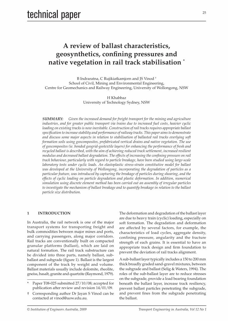
In Australia, the rail network is one of the major transport systems for transporting freight and bulk commodities between major mines and ports, and carrying passengers, along major corridors. Rail tracks are conventionally built on compacted granular platforms (ballast), which are laid on natural formation. The rail track substructure can be divided into three parts, namely ballast, sub-ballast and subgrade (fi gure 1). Ballast is the largest component of the track by weight and volume. Ballast materials usually include dolomite, rheolite, gneiss, basalt, granite and quartzite (Raymond, 1979).
The deformation and degradation of the ballast layer
are due to heavy train (cyclic) loading, especially on
soft formation. The degradation and deformation
are affected by several factors, for example, the
characteristics of load cycles, aggregate density,
confining pressure, angularity and the fracture
strength of each grains. It is essential to have an
appropriate track design and fi rm foundation to
prevent the deviation of rail tracks alignment.
A sub-ballast layer typically includes a 150 to 200 mm
thick broadly graded sand-gravel mixtures, between
the subgrade and ballast (Selig & Waters, 1994). The
roles of the sub-ballast layer are to reduce stresses
on the subgrade, provide a load bearing foundation
beneath the ballast layer, increase track resiliency,
prevent ballast particles penetrating the subgrade,
and prevent fi nes from the subgrade penetrating
the ballast.
T08-025 Indraratna.indd 25T08-025 Indraratna.indd 25 16/04/09 11:25 AM16/04/09 11:25 AM
26
Transport Engineering in Australia Vol 12 No 1
“A review of ballast characteristics, geosynthetics ...” – Indraratna, Rujikiatkamjorn, Vinod & Khabbaz
Figure 1: Components of a ballasted rail track – (a) lateral view and (b) longitudinal view(after Selig & Waters, 1994).
The subgrade is comprised of the natural formation of soil, fi ll material or a combination of both. Its key role is to provide a stable foundation to the track. In soft formation areas, high volumes of plastic clays can sustain the excess pore water pressures during both static and cyclic loading. The excessive pore water pressures considerably decrease the bearing capacity of the undrained formation, leading to overall track failure.
In this paper, the deformation and breakage behaviour of ballast under static and dynamic loading conditions are discussed. The prospective use of different types of geosynthetics to improve the performance of fresh and recycled ballast is investigated. The advantages of increasing the confi ning pressure on rail tracks are emphasised in relation to particle breakage. The ballast breakage under cyclic loading is simulated using a 2D discrete element method (DEM) utilising the software PFC2D
to study ballast breakage and to quantify breakage in relation to the particle size distribution.
2 CHARACTERISTICS OF BALLAST
Ballast is widely used as a component of rail tracks throughout the world. Rails are carried by sleepers, which are embedded on a compacted ballast layer. A common problem with this type of track is the premature degradation of ballast due to increasing traffi c passage (number of load cycles) and load. The major functions of ballast are: (i) distributing load from sleepers, (ii) damping of dynamic loads, (iii) providing lateral resistance, and (iv) providing free draining conditions. To elucidate this point, the important geotechnical properties of ballast are discussed below.
2.1 Shear strength
The shear strength of ballast can be considered to vary with the applied stress range based on the Mohr-Coulomb theory. Indraratna et al (1997) and Ramamurthy (2001) have shown that shear strength response is observed to be a function of confi ning pressure. The constant cohesion intercept, c, and
(a) (b)
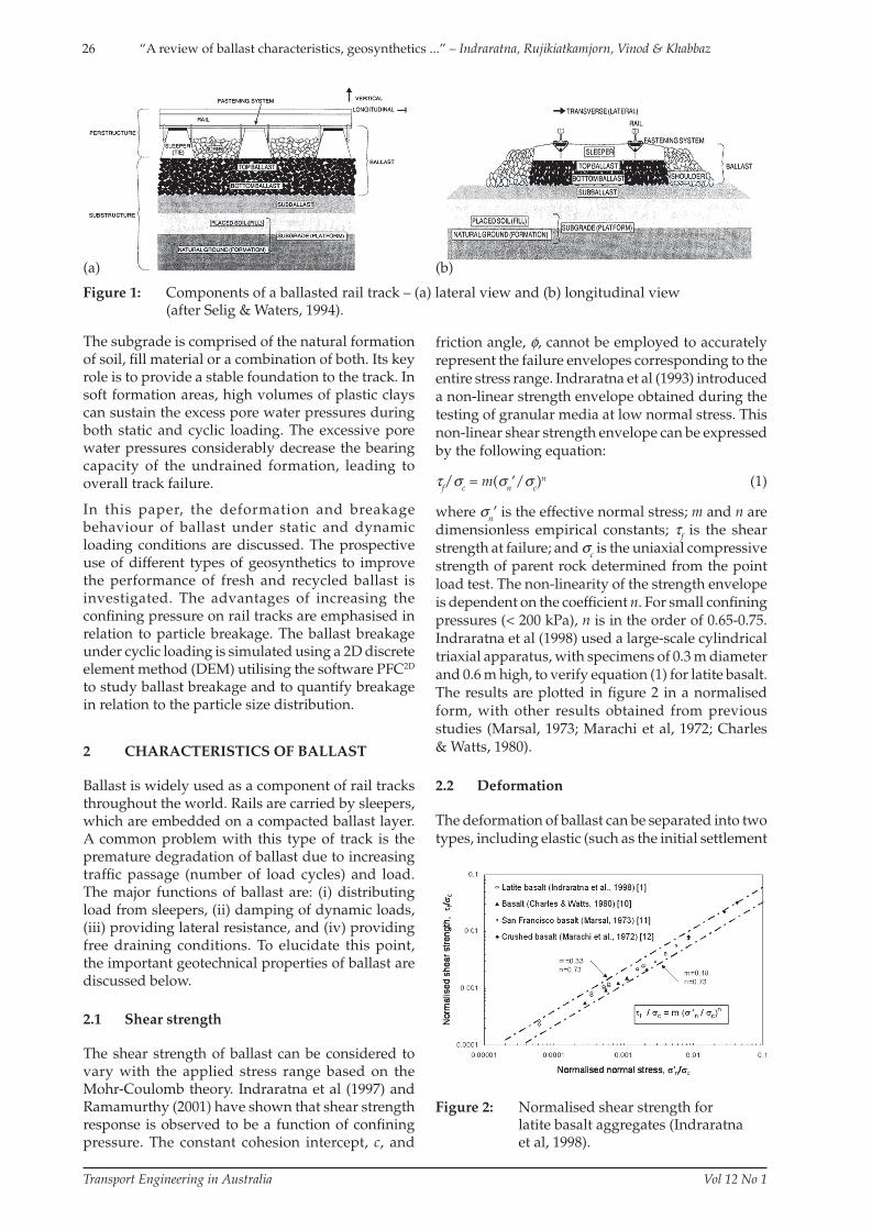
Figure 2: Normalised shear strength forlatite basalt aggregates (Indraratnaet al, 1998).
friction angle, φ, cannot be employed to accurately
represent the failure envelopes corresponding to the
entire stress range. Indraratna et al (1993) introduced
a non-linear strength envelope obtained during the
testing of granular media at low normal stress. This
non-linear shear strength envelope can be expressed
by the following equation:
τf/σc = m(σn’/σc)n (1)
where σn’ is the effective normal stress; m and n are
dimensionless empirical constants; τf is the shear
strength at failure; and σc is the uniaxial compressive
strength of parent rock determined from the point
load test. The non-linearity of the strength envelope
is dependent on the coeffi cient n. For small confi ning
pressures (< 200 kPa), n is in the order of 0.65-0.75.
Indraratna et al (1998) used a large-scale cylindrical
triaxial apparatus, with specimens of 0.3 m diameter
and 0.6 m high, to verify equation (1) for latite basalt.
The results are plotted in fi gure 2 in a normalised
form, with other results obtained from previous
studies (Marsal, 1973; Marachi et al, 1972; Charles
& Watts, 1980).
2.2 Deformation
The deformation of ballast can be separated into two
types, including elastic (such as the initial settlement
T08-025 Indraratna.indd 26T08-025 Indraratna.indd 26 16/04/09 11:25 AM16/04/09 11:25 AM

27
Transport Engineering in Australia Vol 12 No 1
“A review of ballast characteristics, geosynthetics ...” – Indraratna, Rujikiatkamjorn, Vinod & Khabbaz
due to the compaction of ballast) and plastic (due to breakage of ballast particles). Settlement or deformation of ballast may not be a serious issue if it is occurring equally along the length of the track (Selig & Waters, 1994). In fact, differential (local) track deformation is more crucial than the overall track settlement. Over 50% of the total settlement of railway tracks (both differential and uniform) is in the ballast layer (Suiker, 1997; Ionescu et al, 1998). Based on an experimental investigation, Jeffs & Marich (1987) concluded that the relationship between the number of load cycles and settlement of ballast would be non-linear. They suggested the following equation for determining the rail track vertical deformation:
SN = a(1 + klogN) (2)
where SN is the settlement of ballast at N load cycles; a is the settlement at fi rst cycle; and k is an empirical constant depending on initial density, ballast and reinforcement type and moisture content. Indraratna et al (2000) introduced another relationship for settlement under dynamic load represented by a power-function of the number of load cycles as follows:
SN = aNb (3)
where a and b are empirical coeffi cients determined from non-linear regression analysis. Equation (3) can be used to model the ballast settlement, as shown in fi gure 3. It is noted that the coeffi cient a depends only on the variation of the applied load, whereas the coeffi cient b remains constant.
2.3 Factors affecting ballast degradation
Cyclic loading and vibration, temperature and moisture fluctuation, as well as impact load on ballast, may affect ballast degradation. According to Raymond & Diyaljee (1979), particle degradation can occur in three ways:
Figure 3: Effect of load cycles and axle loads on settlement (Indraratna et al, 2000).
Figure 4: Particle size distributions used in the triaxial tests, along with their uniformity coeffi cients, Cu, initial void ratios, e
0, and permeability
coeffi cients, k0 (Indraratna et al, 2003).
(i) The breakage of angular projections of particles, which occurs during the initial settlement of ballast.
(ii) The breakage of particles into equal parts, which infl uences the long-term deformation, stability and safety of rail tracks.
(iii) The grinding-off of small-scale asperities, leading to ballast fouling.
Since ballast particles are considered to be angular aggregates, most breakage occurs due to corner degradation and attrition, although splitting is also observed. The factors controlling particle degradation is described below.
2.3.1 Particle size distribution
The grain size distribution of ballast signifi cantly controls track performance, which should provide suffi cient shear strength and the porosity to allow free drainage. To determine the effects of grain size distribution on deformation and degradation behaviour of ballast, large-scale cyclic triaxial tests were conducted on four different distributions of basalt aggregate (Indraratna et al, 2003). Figure 4 shows the gradation and void ratio of the ballast specimens. An effective confi ning pressure of 45 kPa was applied. In order to simulate the train axle loads at a relatively high speed, cyclic loading with a maximum 300 kPa deviator stress was applied at a frequency of 20 Hz.
Figure 5 illustrates the relationship between the coeffi cient of uniformity (Cu) and particle breakage. Ballast breakage decreases when the value of Cu increases, with the exception of the gap-graded
T08-025 Indraratna.indd 27T08-025 Indraratna.indd 27 16/04/09 11:25 AM16/04/09 11:25 AM

28
Transport Engineering in Australia Vol 12 No 1
“A review of ballast characteristics, geosynthetics ...” – Indraratna, Rujikiatkamjorn, Vinod & Khabbaz
specimen. The gap-graded ballast excluded particle
sizes that were found to be highly vulnerable to
breakage. Therefore, the gap-graded specimen
shows a smaller amount of breakage and higher wet
attrition value than the uniform and very uniform
gradations.
The cyclic test results of ballast varying the gradation
indicate that even a modest change in Cu signifi cantly
affects the deformation and breakage behaviour of
ballast. The test results suggest that a distribution
similar to the moderate grading would give improved
track performance with the lower permeability.
Indraratna et al (2004) recommended that a ballast
gradation with a uniformity coeffi cient exceeding
2.2, but not more than 2.6, is most appropriate.
This recommended gradation, which is relatively
well-graded than the current Australian Standard
(Standards Australia, 1996), is presented in fi gure
6. The recommended gradation can normally be
adopted for low speed, light axle load railways, not
for high-speed heavy axle load.
Figure 5: Effect of grading on particle breakage (Indraratna et al, 2004).
Figure 6: Recommended railway ballast grading in comparison with the current Australian Standard grading requirements (Indraratna et al, 2003).
2.3.2 Effect of confi ning pressure
The confi ning pressure on ballast layer has not often been seriously considered as an important factor in conventional rail track design. This is due to the confi ning pressure, applied on tracks by the shoulder ballast and sleepers, is small in comparison with the relatively high vertical stress. The role of confi ning pressure on ballast performance under cyclic loading has been studied by Indraratna et al (2005a) and Lackenby et al (2007) to quantify the optimum confining pressure based on loading and track conditions to reduce the amount of ballast breakage.
Triaxial testing results on ballast have implied that the initial particle size distribution shifts towards smaller particle sizes, with the maximum size unaffected before and after loading, as shown in fi gure 7. An arbitrary boundary of maximum breakage is controlled by the smallest sieve size (2.36 mm in this case) and signifi es a practical upper limit for ballast breakage, extending from d
95 of the
maximum sieve aperture dmax
to the smallest sieve aperture d
min. Based on a laboratory observation, the
Ballast Breakage Index (BBI) has been introduced and defi ned as follows (Indraratna et al, 2005a):
BBI = A/(A + B) (4)
where A is the area as defi ned previously, and B is the potential breakage or the area between the arbitrary boundary of maximum breakage and the fi nal particle size distribution.
The effect of confi ning pressure on particle breakage using the BBI is shown in fi gure 8. The breakage has been divided into three zones namely: (I) the dilatant unstable, (II) the optimum and (III) the compressive stable degradation zones (Indraratna et al, 2005a).
Figure 7: Evaluation of the Ballast Breakage Index (Indraratna et al, 2005a).
T08-025 Indraratna.indd 28T08-025 Indraratna.indd 28 16/04/09 11:25 AM16/04/09 11:25 AM

29
Transport Engineering in Australia Vol 12 No 1
“A review of ballast characteristics, geosynthetics ...” – Indraratna, Rujikiatkamjorn, Vinod & Khabbaz
Figure 8: Effect of confi ning pressure on particle degradation (Indraratna et al, 2005a).
At low confining pressures of region (I) where
σ3′ < 30 kPa, ballast specimens are subjected to rapid
and considerable axial and expansive radial strains.
This leads to an overall volumetric increase or dilation.
In this region, particles do not have adequate time to
rearrange, and due to the excessive axial and radial
strains, considerable degradation occurs via shearing
and attrition of angular projections. Because of the
small confi ning pressures applied here, specimens in
this degradation zone are characterised by a limited
coordination number, as well as relatively small
particle-to-particle contact areas.
As the confi ning pressure is increased to the middle
(optimum) region (30 < σ3′ < 75 kPa), axial strain rate
is greatly reduced due to increased apparent stiffness.
It is noted that the overall volumetric behaviour is
slightly compressive. In this region, particles are
held together in an optimum array with suffi cient
lateral confi nement so as to provide an optimum
contact stress distribution and increased interparticle
contact areas. This leads to the reduction of the risk
Figure 9: Harmonic cyclic loading curve (after Indraratna et al, 2005a).
of breakage associated with stress concentrations,
thereby reducing the wet attrition value. As σ3′ is
increased further to the compressive stable region
(σ3′ > 75 kPa), particles are forced to move against
each other within a limited space for sliding and
rolling. Therefore, breakage is signifi cantly increased.
In this region, particles fail not only at the beginning
of loading when the axial strain rates are the greatest,
but also by the process of fatigue as the number of
cycles increases.
2.4 Resilient modulus of ballast
The cyclic response of granular materials is usually
characterised by the resilient modulus. For repeated
loads in triaxial testing with constant confi ning stress,
the resilient modulus (MR) is defi ned as the ratio of
the applied cyclic deviator stress to the recoverable
(resilient) axial strain during unloading (Seed et al,
1962). Resilient modulus is defi ned by equation (5):
Rr
qM
(5)
where Δq is the difference between qmax
and qmin
, and
εr is the recoverable (resilient) axial strain during
triaxial unloading. As shown in fi gure 10, resilient
modulus (MR) is found to be increasing with number
of cycles, maximum deviator stress magnitude
(qmax,cyc) and confining pressure (Lackenby et al,
2007). Recent research at University of Wollongong
highlights that resilient modulus is infl uenced by
particle breakage. Resilient modulus is found to be
Figure 10: (a) Effect of confi ning pressure and the number of cycles on MR.(b) Effect of q
max,cyc on MR (after Lackenby et al, 2007).
(a)
(b)
T08-025 Indraratna.indd 29T08-025 Indraratna.indd 29 16/04/09 11:25 AM16/04/09 11:25 AM
30
Transport Engineering in Australia Vol 12 No 1
“A review of ballast characteristics, geosynthetics ...” – Indraratna, Rujikiatkamjorn, Vinod & Khabbaz
increasing with particle breakage irrespective of the initial effective confi ning pressure (Indraratna et al, 2008).
3 ANALYSIS OF BALLAST BREAKAGE
3.1 Constitutive modelling of ballast breakage
Indraratna et al (1998) introduced some empirical relationships between the peak principal stress ratio, particle breakage and peak friction angle. The limitation of empirical relationships is only for the failure states of axisymmetric specimens. Subsequently, Indraratna & Salim (2002) developed an analytical model that incorporates the relationship of the deviator stress ratio (q/p′), rate of dilation(dεv/dε
1), corrected friction angle to include dilatancy
(φf), and the rate of energy consumption due to particle breakage. The deviator stress ratio can be shown as:
21
21
1
21
3 1 tan 45 2 3
2 1 tan 45 2
3 / 1 sin
2 1 tan 45 2
v f
v f
g f
v f
d d
d dqp f dB d
p d d
(6)
where dε1 and dεv are the increments of major
principal strain and volumetric strain, respectively. The parameter p′ is the mean effective stress, q is the deviator stress and dBg is the increment of breakage index associated with dε
1. The function f(dBg/dε
1) in
equation (6) can be obtained based on laboratory triaxial testing. A constitutive model that can predict particle breakage under cyclic loads in an assembly of irregular shapes, including the effects of anisotropy is currently being developed at University of Wollongong.
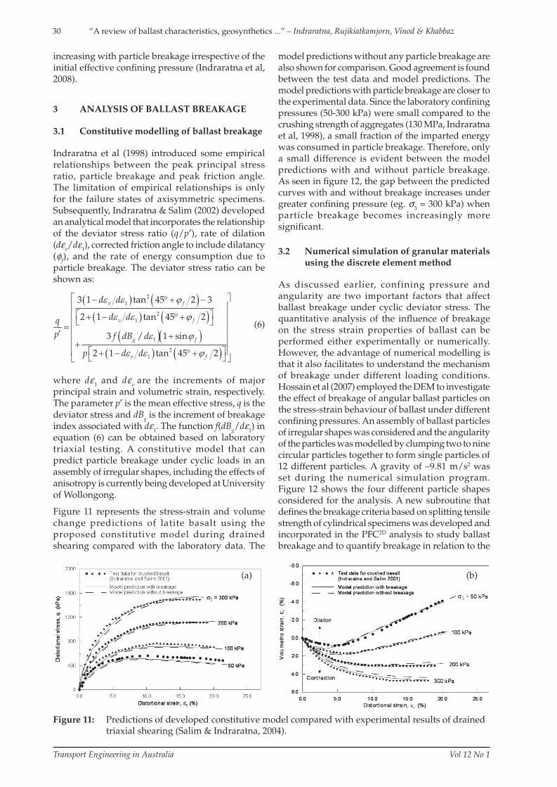
Figure 11 represents the stress-strain and volume change predictions of latite basalt using the proposed constitutive model during drained shearing compared with the laboratory data. The
model predictions without any particle breakage are also shown for comparison. Good agreement is found between the test data and model predictions. The model predictions with particle breakage are closer to the experimental data. Since the laboratory confi ning pressures (50-300 kPa) were small compared to the crushing strength of aggregates (130 MPa, Indraratna et al, 1998), a small fraction of the imparted energy was consumed in particle breakage. Therefore, only a small difference is evident between the model predictions with and without particle breakage. As seen in fi gure 12, the gap between the predicted curves with and without breakage increases under greater confi ning pressure (eg. σ
3 = 300 kPa) when
particle breakage becomes increasingly more signifi cant.
3.2 Numerical simulation of granular materials using the discrete element method
As discussed earlier, confining pressure and angularity are two important factors that affect ballast breakage under cyclic deviator stress. The quantitative analysis of the infl uence of breakage on the stress strain properties of ballast can be performed either experimentally or numerically. However, the advantage of numerical modelling is that it also facilitates to understand the mechanism of breakage under different loading conditions. Hossain et al (2007) employed the DEM to investigate the effect of breakage of angular ballast particles on the stress-strain behaviour of ballast under different confi ning pressures. An assembly of ballast particles of irregular shapes was considered and the angularity of the particles was modelled by clumping two to nine circular particles together to form single particles of 12 different particles. A gravity of –9.81 m/s2 was set during the numerical simulation program. Figure 12 shows the four different particle shapes considered for the analysis. A new subroutine that defi nes the breakage criteria based on splitting tensile strength of cylindrical specimens was developed and incorporated in the PFC2D analysis to study ballast breakage and to quantify breakage in relation to the
Figure 11: Predictions of developed constitutive model compared with experimental results of drained triaxial shearing (Salim & Indraratna, 2004).
(a) (b)
T08-025 Indraratna.indd 30T08-025 Indraratna.indd 30 16/04/09 11:25 AM16/04/09 11:25 AM

31
Transport Engineering in Australia Vol 12 No 1
“A review of ballast characteristics, geosynthetics ...” – Indraratna, Rujikiatkamjorn, Vinod & Khabbaz
Figure 12: Particle shape and size considered in the numerical simulation (after Hossain et al, 2007).
particle size distribution. More details on the DEM can be found elsewhere (eg. Hossain et al, 2007).
The comparison of BBI with laboratory experiments verifi es that a defi nite minimum BBI is at 30 kPa, but the experimental results tend to show a range of 50 to 60 kPa for the minimum BBI (fi gure 13). At low values of σ
3 (<30 kPa),
corner breakage is pronounced
due to dilation. At increase values of σ3 (>30 kPa)
the granular materials undergoes compression. At such confi ning pressures, granular assembly suffers from both corner breakage and splitting. Figure 14 compares the settlement of ballast assembly with and without breakage at a confi ning pressure of 10 kPa, where the shaded zone represents the effect of particle breakage on the settlement. Figure 14 highlights an additional 20 mm settlement due to breakage, which is equivalent to an extra 3.5% of axial strain. As explained earlier, a small confi ning pressure permits greater dilation of particles. Nevertheless, in all cases of σ
3 it was found that breakage zones are
located closer to the top loading platen (fi gure 15) due to the lower coordination number between the irregular particles. In addition, research on the effect of frequency (high speed trains) and anisotropy on the behaviour of granular materials are being carried out at University of Wollongong.
4 BALLASTED RAIL TRACK IMPROVEMENT: FROMTHEORY TO PRACTICE
This section discusses the need for improving rail tracks that are more resistant to future fast trains. The use of geogrids to stabilise the ballast bed, the increased confi ning pressure on tracks to minimise lateral strains, and using native vegetation in the vicinity of the rail corridors to stabilise track are some aspects that are imperative to consider through sound research evidence conducted at the University of Wollongong.
Figure 13: Breakage index variation with different confi ning pressures (after Hossain et al, 2007).
Figure 14: Settlement versus number of cycles with and without breakage (after Hossain et al, 2007).
Figure 15: Breakage of particles at locations near the top plate (after Hossain et al, 2007).
4.1 Improvement of recycled
ballast using geosynthetics
The deformation and degradation behaviour of fresh
and recycled ballast was investigated in a large-scale
cubical triaxial chamber (fi gure 16). The stabilisation
aspects of recycled ballast using various types of
geosynthetics were also studied in the model tests
(Indraratna et al, 2003). Three types of geosynthetics
were used including woven geotextiles, geogrids
and geocomposites (bonded geogrids and non-
T08-025 Indraratna.indd 31T08-025 Indraratna.indd 31 16/04/09 11:25 AM16/04/09 11:25 AM

32
Transport Engineering in Australia Vol 12 No 1
“A review of ballast characteristics, geosynthetics ...” – Indraratna, Rujikiatkamjorn, Vinod & Khabbaz
Figure 16: Cubical triaxial apparatus with dynamic actuator designed at University of Wollongong.
Figure 17: Settlement of wet fresh and recycled ballast with and without geosynthetics (Indraratna et al, 2004).
woven geotextiles). The testing methods together
with complete fi ndings and discussions have been
reported by Indraratna et al (2004).
Figure 17 shows the settlement of fresh ballast
without any reinforcement, and recycled ballast
with and without the inclusion of geosynthetics at
the bottom of the ballast layer. The test results imply
that wet recycled ballast (without any geosynthetic
inclusion) generates signifi cant settlement, because
water acts as a lubricant thereby reducing the
frictional resistance and promoting particle slippage.
The combination of reinforcement by the geogrid,
and the fi ltration and separation functions provided
by the non-woven geotextile component (of the
geocomposite) reduces the lateral spreading and
fouling of ballast.
In order to determine the optimum location of
geosynthetics for improving the deformation
characteristics of recycled ballast, a fi nite element
analysis (PLAXIS) was used (Indraratna et al,
2005a). The large-scale cubical triaxial apparatus was
discretised using the mesh shown in fi gure 18. Due to
Figure 18: Finite element mesh used in PLAXIS for the cubical triaxial apparatus (Indraratna et al, 2005a).
Figure 19: Optimum location of geosyntheticsby the fi nite elements (Indraratnaet al, 2005a).
symmetry, only one half of the rig was simulated in
the numerical model. The location of geosynthetics
beneath the sleeper was initially at 300 mm depth (ie.
at the ballast capping interface), and then decreased
at intervals of 50 mm so that the placement of
geosynthetics could be examined at 250, 200, 150
and 100 mm, respectively. There is a threshold
depth (between 150 to 200 mm) below which the
geosynthetics do not contribute any further, but in
fact provide less assistance to settlement reduction
and increase ballast degradation. According to
fi gure 19, the optimum location of geosynthetics for
improving the deformation characteristics of recycled
ballast may be taken as 200 mm. Nevertheless, for a
conventional ballast thickness of 300 mm, placement
of geosynthetics at the optimum location (ie. at 200
T08-025 Indraratna.indd 32T08-025 Indraratna.indd 32 16/04/09 11:25 AM16/04/09 11:25 AM
33
Transport Engineering in Australia Vol 12 No 1
“A review of ballast characteristics, geosynthetics ...” – Indraratna, Rujikiatkamjorn, Vinod & Khabbaz
mm) may not be feasible for maintenance reasons. Consequently, in such cases, the layer of geosynthetics may still be located conveniently at the bottom of the ballast bed (ie. ballast/capping interface).
4.2 Track modifi cations forincreased confi nement
As discussed previously, the confi ning pressure plays an important role in controlling rail track deformation in both the vertical and lateral directions (Indraratna et al, 2005a). The lateral force produced by continuously welded rail on a curved track depends on the train speed, axle loads, temperature changes, curvature of the track (degree of the curve) and slope of the track. The buckling of the track is usually due to the build up of stress in the welded rail as a result of high temperature change and insuffi cient lateral stability (confi nement) to support the track.
Some measures for increasing track confi nement include (Indraratna et al, 2005a):
• reducing sleeper spacing
• increasing height of shoulder ballast
• inclusion of a geosynthetic layer at the ballast/sub-ballast layer interface
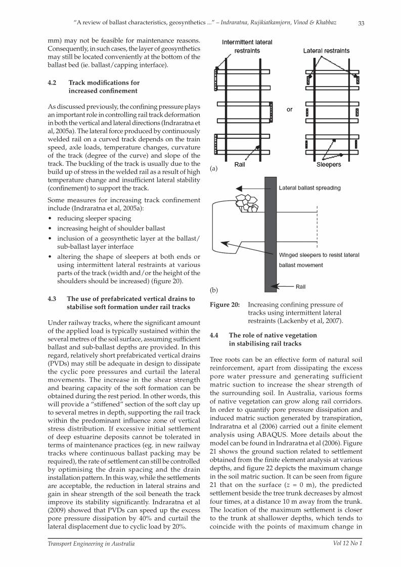
• altering the shape of sleepers at both ends or using intermittent lateral restraints at various parts of the track (width and/or the height of the shoulders should be increased) (fi gure 20).
4.3 The use of prefabricated vertical drains to stabilise soft formation under rail tracks
Under railway tracks, where the signifi cant amount of the applied load is typically sustained within the several metres of the soil surface, assuming suffi cient ballast and sub-ballast depths are provided. In this regard, relatively short prefabricated vertical drains (PVDs) may still be adequate in design to dissipate the cyclic pore pressures and curtail the lateral movements. The increase in the shear strength and bearing capacity of the soft formation can be obtained during the rest period. In other words, this will provide a “stiffened” section of the soft clay up to several metres in depth, supporting the rail track within the predominant infl uence zone of vertical stress distribution. If excessive initial settlement of deep estuarine deposits cannot be tolerated in terms of maintenance practices (eg. in new railway tracks where continuous ballast packing may be required), the rate of settlement can still be controlled by optimising the drain spacing and the drain installation pattern. In this way, while the settlements are acceptable, the reduction in lateral strains and gain in shear strength of the soil beneath the track improve its stability signifi cantly. Indraratna et al (2009) showed that PVDs can speed up the excess pore pressure dissipation by 40% and curtail the lateral displacement due to cyclic load by 20%.
Figure 20: Increasing confi ning pressure of tracks using intermittent lateral restraints (Lackenby et al, 2007).
4.4 The role of native vegetation
in stabilising rail tracks
Tree roots can be an effective form of natural soil
reinforcement, apart from dissipating the excess
pore water pressure and generating sufficient
matric suction to increase the shear strength of
the surrounding soil. In Australia, various forms
of native vegetation can grow along rail corridors.
In order to quantify pore pressure dissipation and
induced matric suction generated by transpiration,
Indraratna et al (2006) carried out a fi nite element
analysis using ABAQUS. More details about the
model can be found in Indraratna et al (2006). Figure
21 shows the ground suction related to settlement
obtained from the fi nite element analysis at various
depths, and fi gure 22 depicts the maximum change
in the soil matric suction. It can be seen from fi gure
21 that on the surface (z = 0 m), the predicted
settlement beside the tree trunk decreases by almost
four times, at a distance 10 m away from the trunk.
The location of the maximum settlement is closer
to the trunk at shallower depths, which tends to
coincide with the points of maximum change in
(a)
(b)
T08-025 Indraratna.indd 33T08-025 Indraratna.indd 33 16/04/09 11:25 AM16/04/09 11:25 AM

34
Transport Engineering in Australia Vol 12 No 1
“A review of ballast characteristics, geosynthetics ...” – Indraratna, Rujikiatkamjorn, Vinod & Khabbaz
suction obtained from the analysis (fi gure 22). This indicates that native biostabilisation improves the shear strength of soil by increasing the matric suction, thus decreasing the soil movements. In this regard, native vegetation generating soil suction is comparable to the role of PVDs with vacuum pressure, in terms of improved drainage (pore water pressure dissipation) and associated increase in shear strength. It is recommended that proper vegetation with optimum distance from the track can be grown along the track corridors, as it can reduce moisture through root water uptake, increase the shear strength and stiffness by increasing matric suction, and, as a secondary effect, control erosion.
5 CONCLUSIONS
The engineering mechanics of ballast and the stabilisation of ballasted tracks with geosynthetics have been described through laboratory, theoretical modelling and numerical simulations. The results show that the ballast particle size distribution and confining pressure have a significant influence
Figure 21: Ground suction related settlement at various depths (Indraratna et al, 2006).
Figure 22: Predicted soil matric suction at various depths (Indraratna et al, 2006).
on ballast degradation. The uniformly graded distribution of ballast is the most prone to breakage and ballast breakage is minimal at confining pressures ranges from 30-75 kPa. Resilient modulus was found to be infl uenced by number of cycles, maximum deviator stress, confi ning pressure and particle breakage. Numerical simulation using the DEM clearly captures the realistic behaviour of granular material during cyclic loading similar to laboratory experiments. The results highlighted that particle breakage and confi ning pressure has a signifi cant infl uence of the permanent deformation behaviour of ballast.
The deformations of fresh and recycled ballast vary with the number of load cycles, and the extent of degradation and settlement in fresh and recycled ballast reduces with the insertion of geosynthetics. The use of bonded geosynthetics also prevents clay pumping into ballast voids under cyclic loads, providing an additional drainage facility. This indicates the potential use of geosynthetics for enhancing ballast characteristics. The results also indicate that short PVDs (6-8 m) can be used under new rail tracks to dissipate cyclic excess pore pressure and curtail lateral displacements to improve stability. The dissipation of the pore water pressure during the rest period makes the track more stable for the next loading stage. The tree roots facilitates to dissipate the excess pore water pressure, and generate suffi cient matric suction to increase the shear strength of the surrounding soil close to the rail track and thus reduces settlement and lateral movements. In addition, PVDs and tree root will enhance the drainage of subsoils, which will reduce the risk of clay pumping.
ACKNOWLEDGEMENT
The authors wish to thank the CRC for Railway Engineering and Technologies (Australia) for its continuous support. A number of current and past doctoral students, namely Dr Daniela Ionescu, Dr Joanne Lackenby, Dr Wadud Salim, Dr Mohamed Shahin, Mr Zakir Hossain and Dr Behzad Fatahi, have participated to the contents of this paper and their contributions are greatly acknowledged. More elaborate details of the contents discussed in the paper can also be found in previous publications of the fi rst author and his research students in Geotechnique, ICE Proceedings (Geotechnical Engineering), ASCE, Canadian Geotechnical Journals, Geomechanics and Geoengineering since the mid 1990s.
REFERENCES
Charles, J. A. & Watts, K. S. 1980, “The infl uence of confining pressure on the shear strength of compacted rockfi ll”, Geotechnique, Vol. 30, No. 4, pp. 353-367.
T08-025 Indraratna.indd 34T08-025 Indraratna.indd 34 16/04/09 11:25 AM16/04/09 11:25 AM
35
Transport Engineering in Australia Vol 12 No 1
“A review of ballast characteristics, geosynthetics ...” – Indraratna, Rujikiatkamjorn, Vinod & Khabbaz
Hossain, Z., Indraratna, B., Darve, F. & Thakur, P. K. 2007, “DEM analysis of angular ballast breakage under cyclic loading”, Geomechanics and Geoengineering: An International Journal, Vol. 2, No. 3, pp. 175-181.
Indraratna, B. & Salim, W. 2002, “Modeling of particle breakage of coarse aggregates incorporating strength and dilatancy”, Geotechnical Engineering, Proceedings of the Institution of Civil Engineers, London, Vol. 155, No. 4, pp. 243-252.
Indraratna , B . , Wi jewardena , L . S . S . & Balasubramaniam, A. S. 1993, “Large-scale testing of greywacke rockfi ll”, Geotechnique, Vol. 43, No. 1, pp. 37-51.
Indraratna, B., Ionescu, D., Christie, D. & Chowdhury, R. 1997, “Compression and Degradation of Railway Ballast under One-dimensional Consolidation”, Australian Geomechanics Journal, December, pp. 48-61.
Indraratna, B., Ionescu, D. & Christie, D. 1998, “Shear behaviour of railway ballast based on large-scale triaxial tests”, Geotechnical and Geoenvironmental Engineering, ASCE, Vol. 124, No. 5, pp. 439-439.
Indraratna, B., Khabbaz, H. & Lackenby, J. 2003, “Behaviour of railway ballast under dynamic loads based on large-scale triaxial testing”, Proceedings of AusRAIL Plus 2003, Sydney, 8 p.
Indraratna, B., Salim, W. & Khabbaz, H. 2004, “Stabilization of rail tracks employing geosynthetics with recycled ballast”, 5 International Conf. on Ground Improvement, Kuala Lumpur, Malaysia, pp. 27-40.
Indraratna, B., Lackenby, J. & Christie, D. 2005a, “Effect of confi ning pressure on the degradation of ballast under cyclic loading”, Geotechnique, Institution of Civil Engineers, UK, Vol. 55, No. 4, pp. 325-328.
Indraratna, B., Shahin, M. A. & Salim, M. W. 2005b, “Use of geosynthetics for stabilizing recycled ballast in railway track substructures”, North American Geosynthetics Society (NAGS)– Geosynthetics Institute (GSI) Conference, Las Vegas, Nevada, CD-ROM.
Indraratna, B., Fatahi, B. & Khabbaz, H. 2006, “Numerical analysis of matric suction effects of tress roots”, Geotechnical Engineering, Proceedings of the Institution of Civil Engineers, Vol. 159, No. GE2, pp. 77-90.
Indraratna, B., Vinod, J. S. & Lackenby, J. 2008, “Infl uence of particle breakage on resilient modulus of railway ballast”, Geotechnique, in press.
Indraratna, B., Attya, A. & Rujikiatkamjorn, C. 2009, “Experimental investigation on effectiveness of a vertical drain under cyclic loads”, International Journal for Geotechnical and Geoenvironmental Engineering, ASCE, in press.
Ionescu, D., Indraratna, B. & Christie, H. D. 1998, “Behaviour of railway ballast under dynamic loads”, Thirteenth Southeast Asian Geotechnical Conference, Taiwan, pp. 69-74.
Jeffs, T. & Marich, S. 1987, “Ballast characteristics in the laboratory”, Conf. on Railway Engineering, Perth, Australia, pp. 141-147.
Lackenby, J., Indraratna, B. & McDowel, G. 2007, “The Role of Confi ning Pressure on Cyclic Triaxial Behaviour of Ballast”, Geotechnique, Institution of Civil Engineers, UK, Vol. 57, No. 6, pp. 527-536.
Marachi, N. D., Chan, C. K. & Seed, H. B. 1972, “Evaluation of properties of rockfill materials”, Journal of Soil Mech. and Found. Division., ASCE, Vol. 96, No. 6, pp. 95-114.
Marsal, R. J. 1973, Embankment dam engineering – mechanical properties of rockfi ll, Wiley Publication, New York, pp. 109-200.
Ramamurthy, T. 2001, “Shear strength response of some geological materials in triaxial compression”, International Journal of Rock Mechanics and Mining Sciences, Vol. 38, pp. 683-697.
Raymond, G. P. 1979, “Railroad Ballast Prescription: State-of-the-Art”, Journal of the Geotechnical Engineering Division, ASCE, Vol. 105, No. GT2, pp. 305-322.
Raymond, G. P. & Diyaljee, V. A. 1979, “Railroad ballast load ranking classifi cation”, Journal of the Geotechnical Engineering Division, ASCE, Vol. 105, No. 10, pp. 1133-1153.
Salim, W. & Indraratna, B. 2004, “A new elasto-plastic constitutive model for granular aggregates incorporating particle breakage”, Canadian Geotechnical Journal, Vol. 41, pp. 657-671.
Seed, H. B., Chan, C. K. & Lee, C. E. 1962, “Resilience characteristics subgrade soils and their relation to fatigue failures”, Proc. Int. Conf. Structural Design of Asphalt Pavements, Ann Harbor, Michigan, pp. 611-636.
Selig, E. T. & Waters, J. M. 1994, Track Geotechnology and Substructure Management, Thomas Telford, London.
Standards Australia, 1996, AS2758.7 Aggregates and rock for engineering purposes. Part 7: Railway ballast, NSW.
T08-025 Indraratna.indd 35T08-025 Indraratna.indd 35 16/04/09 11:25 AM16/04/09 11:25 AM
36
Transport Engineering in Australia Vol 12 No 1
“A review of ballast characteristics, geosynthetics ...” – Indraratna, Rujikiatkamjorn, Vinod & Khabbaz
BUDDHIMA INDRARATNA
Prof Buddhima Indraratna is Professor of Civil Engineering at the University of Wollongong, Head of Postgraduate Research in the Faculty of Engineering and leader of the current Co-operative Research Centre for Railway Engineering at the University of Wollongong. He has a PhD in Civil (Geotechnical) Engineering from the University of Alberta, Edmonton, Canada, 1987, an MSc in Soil Mechanics and Engineering Seismology, from Imperial College, University of London, 1983, and a BSc (Honours) in Civil Engineering from the same institution. Through industry involvement and ARC and CRC projects, Buddhima has addressed both fundamental and applied issues related to rail track instability. Some recent research developments have contributed towards changes in track specifi cations and guidelines used by RailCorp (NSW) and ARTC, and their implementation in recent track construction in Bulli (near Wollongong) and Sandgate (near Newcastle).
CHOLACHAT RUJIKIATKAMJORN
Dr Cholachat Rujikiatkamjorn is an early career researcher whose expertise is in the area of ground improvement of soft and unstable soils. Recently, he received 2008 IACMAG Junior Paper Awards and a Trailblazer Award 2006 for the innovation and commercial potential of his research on stabilisation of highly compressible soils. His thesis is focused on the development of the analytical modelling of ground improvement by vacuum preloading. In the model, the effectiveness of vacuum pressure applied along the drain is considered. Subsequently, Cholachat has also incorporated his model into the fi nite element code to analyse some case histories, including the embankment at the site of Second Bangkok International Airport (SBIA) stabilised with prefabricated vertical drains.
JAYAN VINOD
Dr Jayan S Vinod is currently a lecturer at University of Wollongong. He received his Doctorate degree from Indian Institute of Science, Bangalore, in the area of Geotechnical Engineering. He has worked as a research fellow in one of the ARC Linkage project on chemical stabilisation at the University of Wollongong. Jayan is a member/life member of many professional societies. His research interests are in the area of numerical modelling of granular materials and soil dynamics, and earthquake engineering. He has published over 26 publications, including 10 peer-reviewed journal articles, one edited proceeding and book chapter, and 15 referred conference papers, three of where were keynote papers.
HADI KHABBAZ
Dr Hadi Khabbaz is a senior Lecturer in Geotechnical Engineering at the University of Technology Sydney. He received his PhD from the University of New South Wales in 1997. He has an MSc in Geo-environmental Engineering from Shiraz University, Iran, and a BSc (Honours) in Civil Engineering from the same institution. He has been involved in soil behaviour modelling and ground improvement research since 1993. He has taken an active role in conducting research in the characterisation and remediation of problematic soils. His research has focused on the theoretical and numerical analysis of soft soils, granular particles and unsaturated porous media with strong applications to real life engineering problems. His early work on unsaturated soil mechanics has been increasingly cited in literature and considered as a signifi cant contribution to the fi eld.
T08-025 Indraratna.indd 36T08-025 Indraratna.indd 36 16/04/09 11:25 AM16/04/09 11:25 AM