a quick guide to temperature sensors and calibration quick guide to... · a quick guide to...
TRANSCRIPT

A Quick Guide to Temperature Sensors and Calibration
Many articles start with a definition of temperature and look at the fundamentals of heat and thermodynamics and
may define temperature as the potential for heat transfer. As this is a practical guide we can focus on our
experience of temperature, perhaps we might consider temperature as “a degree of hotness” and the question
might be how we can know how hot is the liquid in a tank, or how can we be confident in the measurement that
we are attempting to make?
Temperature is a “derived metrology”, this means we cannot measure temperature directly; we have to measure
it indirectly. We may measure the height of a column of mercury in a Liquid in Glass (LIG) thermometer or the
resistance of a thermistor, or the voltage difference from a thermocouple. These types of thermometers are all
“contact thermometers”. There are also thermometers that can measure temperature by measuring the thermal
radiation that is emitted by all objects. The radiation is focussed onto a photo-detector; these thermometers are
“non contact” types as no direct contact is made to the object being measured. These thermometer types are not
discussed further in this article.
Practical Challenges
A challenge in making good measurements is to ensure that the temperature sensor is at the same temperature as
the body of interest; that is the sensor and the object being measured are in “thermal equilibrium”.
The most commonly used temperature sensor in industry is the thermocouple. Thermocouples can be low cost,
rugged and useable over wide ranges. A thermocouple relies on the Seebeck effect, where a voltage will be
produced along a wire where there is a temperature gradient. Thermocouples are constructed from two dissimilar
metals. The voltage output from a thermocouple is dependent on the temperature difference between the hot
(measuring) junction and the cold junction (reference). A thermocouple indicator will employ a separate sensor to
measure the cold junction although in laboratories, for higher accuracy, the cold junction is often maintained in an
ice flask or other apparatus at 0°C.
It is a misconception that the output voltage is generated at the junction (or tip) of the thermocouple and this
junction is the “sensor”. This is incorrect; the Seebeck voltage is generated in the wire where the temperature
gradient is, with the output voltage proportional to the temperature difference between the two junctions.

Resistance thermometers, which employ a Resistance
Temperature Detector (RTD), are also widely used in
industrial instrumentation. The most popular type is the
Platinum Resistance Thermometer (PRT), compared to
thermocouples they tend to have narrower ranges and
higher cost with the potential for higher accuracy
measurement.
PRTs fall into two basic types, film types and wire wound
types. The former consist of thin film of platinum on a
substrate whilst wire wound devices use a coil of platinum
wire and are capable of tighter tolerances.
Sensor Selection
Selecting an appropriate sensor is important if we are to make good measurements, not only choosing a correct
temperature range but also a suitable physical construction and “sensing length”.
This can be illustrated by an example, the diagram
shows a metal block, the block is a few degrees
cooler at the top than at the bottom meaning
there is a temperature gradient.
In it are placed three different types of
temperature sensor. One a PRT has a sensing
length of 20mm, a thermocouple and a dial
thermometer with an extended sensing length.
All three thermometers will read differently, the
thermocouple output is proportional to the
temperature difference between the hot and cold
junctions, the resistance thermometer integrating
the value over the length of its sensing coil, and
the dial thermometer displays the temperature
over the length of the bulb.
Even in a “perfect” block, with no temperature gradient, different thermometers might report different values for
the same block or bath temperature.
In the next diagram a thermometer is immersed a short distance into a tank of oil at
a uniform temperature of 250°C. Thermometer A is not immersed deeply enough
to allow it to reach the same temperature as the oil. It is not in thermal equilibrium.
There is a flow of heat along the stem and the thermometer will be a different
temperature than the oil due to stem conduction or immersion error. It will
therefore report a lower value than thermometer B immersed at a greater depth.
The minimum depth of immersion will depend on the thermometer type, the
temperature difference between the oil and the environment and the desired
uncertainty of the measurement. Isotech have a number of resources discussing
stem conduction from a training course to technical articles available on the web.
A Wire Wound RTD
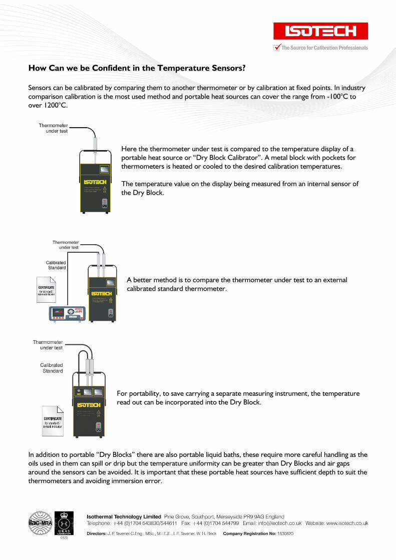
How Can we be Confident in the Temperature Sensors?
Sensors can be calibrated by comparing them to another thermometer or by calibration at fixed points. In industry
comparison calibration is the most used method and portable heat sources can cover the range from -100°C to
over 1200°C.
Here the thermometer under test is compared to the temperature display of a
portable heat source or “Dry Block Calibrator”. A metal block with pockets for
thermometers is heated or cooled to the desired calibration temperatures.
The temperature value on the display being measured from an internal sensor of
the Dry Block.
A better method is to compare the thermometer under test to an external
calibrated standard thermometer.
For portability, to save carrying a separate measuring instrument, the temperature
read out can be incorporated into the Dry Block.
In addition to portable “Dry Blocks” there are also portable liquid baths, these require more careful handling as the
oils used in them can spill or drip but the temperature uniformity can be greater than Dry Blocks and air gaps
around the sensors can be avoided. It is important that these portable heat sources have sufficient depth to suit the
thermometers and avoiding immersion error.

The calibrator needs to provide sufficient temperature uniformity and temperature stability for the test
thermometer and standard to be in thermal equilibrium.
In calibration laboratories larger, non portable, heat sources are widely used. Larger
Calibration Baths and Furnaces can provide greater immersion depth along with
greater stability and uniformity to allow for low uncertainty comparison calibration.
In addition to comparison calibration thermometers can be calibrated at fixed points.
Perhaps the simplest example would be a flask of ice and water, at atmospheric
pressure the temperature will be close to 0°C and thermometers can be checked not
by comparing them to a second thermometer but directly to the “ice point”.
The International Temperature Scale of 1990 (ITS-90) specifies a range of fixed points;
the table shows the points from ITS-90 that apply for a Standard Platinum Resistance
Thermometer.
Note that the ice point is not listed; the Water Triple Point is used, the point at which liquid, solid and vapour are
in equilibrium. This can be achieved to a greater accuracy than the ice point.
FIXED POINT PHYSICAL PROPERTY TEMPERATURE °C INTERPOLATION
THERMOMETER
Argon
Mercury
Water
Gallium
Indium
Tin
Zinc
Aluminium
Silver
Triple Point
Triple Point
Triple Point
Melt Point
Freeze Point
Freeze Point
Freeze Point
Freeze Point
Freeze Point
-189.3442
-38.8344
0.010
29.7646
156.5985
231.928
419.527
660.323
961.78
SPRT
SPRT
SPRT
SPRT
SPRT
SPRT
SPRT
SPRT
SPRT
A Primary Temperature Laboratory realises the ITS-90 fixed points and calibrates SPRTs against these points. The
SPRTs can then be used to calibrate other thermometers using comparison methods.
In a simple example, a thermometers used in industry might be
traceable to an SPRT, with that SPRT being calibrated in ITS-90 Fixed
Points.
Further Reading
Traceable Temperatures by J.V. Nicholas, D.R. White Published by
Wiley; 2nd Edition
Isotech’s Document Library at www.isotech.co.uk
A Water Triple Point Cell